JP6941634B2 - Thermal barrier coating - Google Patents
Thermal barrier coating Download PDFInfo
- Publication number
- JP6941634B2 JP6941634B2 JP2019037751A JP2019037751A JP6941634B2 JP 6941634 B2 JP6941634 B2 JP 6941634B2 JP 2019037751 A JP2019037751 A JP 2019037751A JP 2019037751 A JP2019037751 A JP 2019037751A JP 6941634 B2 JP6941634 B2 JP 6941634B2
- Authority
- JP
- Japan
- Prior art keywords
- layer
- heat shield
- heat
- general formula
- intermediate layer
- Prior art date
- Legal status (The legal status is an assumption and is not a legal conclusion. Google has not performed a legal analysis and makes no representation as to the accuracy of the status listed.)
- Active
Links
Images


Classifications
-
- C—CHEMISTRY; METALLURGY
- C23—COATING METALLIC MATERIAL; COATING MATERIAL WITH METALLIC MATERIAL; CHEMICAL SURFACE TREATMENT; DIFFUSION TREATMENT OF METALLIC MATERIAL; COATING BY VACUUM EVAPORATION, BY SPUTTERING, BY ION IMPLANTATION OR BY CHEMICAL VAPOUR DEPOSITION, IN GENERAL; INHIBITING CORROSION OF METALLIC MATERIAL OR INCRUSTATION IN GENERAL
- C23C—COATING METALLIC MATERIAL; COATING MATERIAL WITH METALLIC MATERIAL; SURFACE TREATMENT OF METALLIC MATERIAL BY DIFFUSION INTO THE SURFACE, BY CHEMICAL CONVERSION OR SUBSTITUTION; COATING BY VACUUM EVAPORATION, BY SPUTTERING, BY ION IMPLANTATION OR BY CHEMICAL VAPOUR DEPOSITION, IN GENERAL
- C23C28/00—Coating for obtaining at least two superposed coatings either by methods not provided for in a single one of groups C23C2/00 - C23C26/00 or by combinations of methods provided for in subclasses C23C and C25C or C25D
- C23C28/30—Coatings combining at least one metallic layer and at least one inorganic non-metallic layer
- C23C28/32—Coatings combining at least one metallic layer and at least one inorganic non-metallic layer including at least one pure metallic layer
- C23C28/321—Coatings combining at least one metallic layer and at least one inorganic non-metallic layer including at least one pure metallic layer with at least one metal alloy layer
- C23C28/3215—Coatings combining at least one metallic layer and at least one inorganic non-metallic layer including at least one pure metallic layer with at least one metal alloy layer at least one MCrAlX layer
-
- F—MECHANICAL ENGINEERING; LIGHTING; HEATING; WEAPONS; BLASTING
- F02—COMBUSTION ENGINES; HOT-GAS OR COMBUSTION-PRODUCT ENGINE PLANTS
- F02C—GAS-TURBINE PLANTS; AIR INTAKES FOR JET-PROPULSION PLANTS; CONTROLLING FUEL SUPPLY IN AIR-BREATHING JET-PROPULSION PLANTS
- F02C7/00—Features, components parts, details or accessories, not provided for in, or of interest apart form groups F02C1/00 - F02C6/00; Air intakes for jet-propulsion plants
- F02C7/24—Heat or noise insulation
-
- B—PERFORMING OPERATIONS; TRANSPORTING
- B32—LAYERED PRODUCTS
- B32B—LAYERED PRODUCTS, i.e. PRODUCTS BUILT-UP OF STRATA OF FLAT OR NON-FLAT, e.g. CELLULAR OR HONEYCOMB, FORM
- B32B15/00—Layered products comprising a layer of metal
- B32B15/04—Layered products comprising a layer of metal comprising metal as the main or only constituent of a layer, which is next to another layer of the same or of a different material
-
- C—CHEMISTRY; METALLURGY
- C23—COATING METALLIC MATERIAL; COATING MATERIAL WITH METALLIC MATERIAL; CHEMICAL SURFACE TREATMENT; DIFFUSION TREATMENT OF METALLIC MATERIAL; COATING BY VACUUM EVAPORATION, BY SPUTTERING, BY ION IMPLANTATION OR BY CHEMICAL VAPOUR DEPOSITION, IN GENERAL; INHIBITING CORROSION OF METALLIC MATERIAL OR INCRUSTATION IN GENERAL
- C23C—COATING METALLIC MATERIAL; COATING MATERIAL WITH METALLIC MATERIAL; SURFACE TREATMENT OF METALLIC MATERIAL BY DIFFUSION INTO THE SURFACE, BY CHEMICAL CONVERSION OR SUBSTITUTION; COATING BY VACUUM EVAPORATION, BY SPUTTERING, BY ION IMPLANTATION OR BY CHEMICAL VAPOUR DEPOSITION, IN GENERAL
- C23C28/00—Coating for obtaining at least two superposed coatings either by methods not provided for in a single one of groups C23C2/00 - C23C26/00 or by combinations of methods provided for in subclasses C23C and C25C or C25D
- C23C28/04—Coating for obtaining at least two superposed coatings either by methods not provided for in a single one of groups C23C2/00 - C23C26/00 or by combinations of methods provided for in subclasses C23C and C25C or C25D only coatings of inorganic non-metallic material
- C23C28/042—Coating for obtaining at least two superposed coatings either by methods not provided for in a single one of groups C23C2/00 - C23C26/00 or by combinations of methods provided for in subclasses C23C and C25C or C25D only coatings of inorganic non-metallic material including a refractory ceramic layer, e.g. refractory metal oxides, ZrO2, rare earth oxides
-
- C—CHEMISTRY; METALLURGY
- C23—COATING METALLIC MATERIAL; COATING MATERIAL WITH METALLIC MATERIAL; CHEMICAL SURFACE TREATMENT; DIFFUSION TREATMENT OF METALLIC MATERIAL; COATING BY VACUUM EVAPORATION, BY SPUTTERING, BY ION IMPLANTATION OR BY CHEMICAL VAPOUR DEPOSITION, IN GENERAL; INHIBITING CORROSION OF METALLIC MATERIAL OR INCRUSTATION IN GENERAL
- C23C—COATING METALLIC MATERIAL; COATING MATERIAL WITH METALLIC MATERIAL; SURFACE TREATMENT OF METALLIC MATERIAL BY DIFFUSION INTO THE SURFACE, BY CHEMICAL CONVERSION OR SUBSTITUTION; COATING BY VACUUM EVAPORATION, BY SPUTTERING, BY ION IMPLANTATION OR BY CHEMICAL VAPOUR DEPOSITION, IN GENERAL
- C23C28/00—Coating for obtaining at least two superposed coatings either by methods not provided for in a single one of groups C23C2/00 - C23C26/00 or by combinations of methods provided for in subclasses C23C and C25C or C25D
- C23C28/30—Coatings combining at least one metallic layer and at least one inorganic non-metallic layer
- C23C28/34—Coatings combining at least one metallic layer and at least one inorganic non-metallic layer including at least one inorganic non-metallic material layer, e.g. metal carbide, nitride, boride, silicide layer and their mixtures, enamels, phosphates and sulphates
- C23C28/345—Coatings combining at least one metallic layer and at least one inorganic non-metallic layer including at least one inorganic non-metallic material layer, e.g. metal carbide, nitride, boride, silicide layer and their mixtures, enamels, phosphates and sulphates with at least one oxide layer
- C23C28/3455—Coatings combining at least one metallic layer and at least one inorganic non-metallic layer including at least one inorganic non-metallic material layer, e.g. metal carbide, nitride, boride, silicide layer and their mixtures, enamels, phosphates and sulphates with at least one oxide layer with a refractory ceramic layer, e.g. refractory metal oxide, ZrO2, rare earth oxides or a thermal barrier system comprising at least one refractory oxide layer
-
- C—CHEMISTRY; METALLURGY
- C23—COATING METALLIC MATERIAL; COATING MATERIAL WITH METALLIC MATERIAL; CHEMICAL SURFACE TREATMENT; DIFFUSION TREATMENT OF METALLIC MATERIAL; COATING BY VACUUM EVAPORATION, BY SPUTTERING, BY ION IMPLANTATION OR BY CHEMICAL VAPOUR DEPOSITION, IN GENERAL; INHIBITING CORROSION OF METALLIC MATERIAL OR INCRUSTATION IN GENERAL
- C23C—COATING METALLIC MATERIAL; COATING MATERIAL WITH METALLIC MATERIAL; SURFACE TREATMENT OF METALLIC MATERIAL BY DIFFUSION INTO THE SURFACE, BY CHEMICAL CONVERSION OR SUBSTITUTION; COATING BY VACUUM EVAPORATION, BY SPUTTERING, BY ION IMPLANTATION OR BY CHEMICAL VAPOUR DEPOSITION, IN GENERAL
- C23C4/00—Coating by spraying the coating material in the molten state, e.g. by flame, plasma or electric discharge
- C23C4/04—Coating by spraying the coating material in the molten state, e.g. by flame, plasma or electric discharge characterised by the coating material
- C23C4/06—Metallic material
- C23C4/073—Metallic material containing MCrAl or MCrAlY alloys, where M is nickel, cobalt or iron, with or without non-metal elements
-
- C—CHEMISTRY; METALLURGY
- C23—COATING METALLIC MATERIAL; COATING MATERIAL WITH METALLIC MATERIAL; CHEMICAL SURFACE TREATMENT; DIFFUSION TREATMENT OF METALLIC MATERIAL; COATING BY VACUUM EVAPORATION, BY SPUTTERING, BY ION IMPLANTATION OR BY CHEMICAL VAPOUR DEPOSITION, IN GENERAL; INHIBITING CORROSION OF METALLIC MATERIAL OR INCRUSTATION IN GENERAL
- C23C—COATING METALLIC MATERIAL; COATING MATERIAL WITH METALLIC MATERIAL; SURFACE TREATMENT OF METALLIC MATERIAL BY DIFFUSION INTO THE SURFACE, BY CHEMICAL CONVERSION OR SUBSTITUTION; COATING BY VACUUM EVAPORATION, BY SPUTTERING, BY ION IMPLANTATION OR BY CHEMICAL VAPOUR DEPOSITION, IN GENERAL
- C23C4/00—Coating by spraying the coating material in the molten state, e.g. by flame, plasma or electric discharge
- C23C4/04—Coating by spraying the coating material in the molten state, e.g. by flame, plasma or electric discharge characterised by the coating material
- C23C4/10—Oxides, borides, carbides, nitrides or silicides; Mixtures thereof
- C23C4/11—Oxides
-
- C—CHEMISTRY; METALLURGY
- C23—COATING METALLIC MATERIAL; COATING MATERIAL WITH METALLIC MATERIAL; CHEMICAL SURFACE TREATMENT; DIFFUSION TREATMENT OF METALLIC MATERIAL; COATING BY VACUUM EVAPORATION, BY SPUTTERING, BY ION IMPLANTATION OR BY CHEMICAL VAPOUR DEPOSITION, IN GENERAL; INHIBITING CORROSION OF METALLIC MATERIAL OR INCRUSTATION IN GENERAL
- C23C—COATING METALLIC MATERIAL; COATING MATERIAL WITH METALLIC MATERIAL; SURFACE TREATMENT OF METALLIC MATERIAL BY DIFFUSION INTO THE SURFACE, BY CHEMICAL CONVERSION OR SUBSTITUTION; COATING BY VACUUM EVAPORATION, BY SPUTTERING, BY ION IMPLANTATION OR BY CHEMICAL VAPOUR DEPOSITION, IN GENERAL
- C23C4/00—Coating by spraying the coating material in the molten state, e.g. by flame, plasma or electric discharge
- C23C4/12—Coating by spraying the coating material in the molten state, e.g. by flame, plasma or electric discharge characterised by the method of spraying
- C23C4/129—Flame spraying
-
- F—MECHANICAL ENGINEERING; LIGHTING; HEATING; WEAPONS; BLASTING
- F01—MACHINES OR ENGINES IN GENERAL; ENGINE PLANTS IN GENERAL; STEAM ENGINES
- F01D—NON-POSITIVE DISPLACEMENT MACHINES OR ENGINES, e.g. STEAM TURBINES
- F01D25/00—Component parts, details, or accessories, not provided for in, or of interest apart from, other groups
- F01D25/08—Cooling; Heating; Heat-insulation
- F01D25/14—Casings modified therefor
- F01D25/145—Thermally insulated casings
-
- F—MECHANICAL ENGINEERING; LIGHTING; HEATING; WEAPONS; BLASTING
- F01—MACHINES OR ENGINES IN GENERAL; ENGINE PLANTS IN GENERAL; STEAM ENGINES
- F01D—NON-POSITIVE DISPLACEMENT MACHINES OR ENGINES, e.g. STEAM TURBINES
- F01D5/00—Blades; Blade-carrying members; Heating, heat-insulating, cooling or antivibration means on the blades or the members
- F01D5/12—Blades
- F01D5/28—Selecting particular materials; Particular measures relating thereto; Measures against erosion or corrosion
-
- B—PERFORMING OPERATIONS; TRANSPORTING
- B32—LAYERED PRODUCTS
- B32B—LAYERED PRODUCTS, i.e. PRODUCTS BUILT-UP OF STRATA OF FLAT OR NON-FLAT, e.g. CELLULAR OR HONEYCOMB, FORM
- B32B2255/00—Coating on the layer surface
- B32B2255/06—Coating on the layer surface on metal layer
-
- B—PERFORMING OPERATIONS; TRANSPORTING
- B32—LAYERED PRODUCTS
- B32B—LAYERED PRODUCTS, i.e. PRODUCTS BUILT-UP OF STRATA OF FLAT OR NON-FLAT, e.g. CELLULAR OR HONEYCOMB, FORM
- B32B2255/00—Coating on the layer surface
- B32B2255/28—Multiple coating on one surface
-
- C—CHEMISTRY; METALLURGY
- C23—COATING METALLIC MATERIAL; COATING MATERIAL WITH METALLIC MATERIAL; CHEMICAL SURFACE TREATMENT; DIFFUSION TREATMENT OF METALLIC MATERIAL; COATING BY VACUUM EVAPORATION, BY SPUTTERING, BY ION IMPLANTATION OR BY CHEMICAL VAPOUR DEPOSITION, IN GENERAL; INHIBITING CORROSION OF METALLIC MATERIAL OR INCRUSTATION IN GENERAL
- C23C—COATING METALLIC MATERIAL; COATING MATERIAL WITH METALLIC MATERIAL; SURFACE TREATMENT OF METALLIC MATERIAL BY DIFFUSION INTO THE SURFACE, BY CHEMICAL CONVERSION OR SUBSTITUTION; COATING BY VACUUM EVAPORATION, BY SPUTTERING, BY ION IMPLANTATION OR BY CHEMICAL VAPOUR DEPOSITION, IN GENERAL
- C23C4/00—Coating by spraying the coating material in the molten state, e.g. by flame, plasma or electric discharge
- C23C4/12—Coating by spraying the coating material in the molten state, e.g. by flame, plasma or electric discharge characterised by the method of spraying
- C23C4/134—Plasma spraying
-
- F—MECHANICAL ENGINEERING; LIGHTING; HEATING; WEAPONS; BLASTING
- F01—MACHINES OR ENGINES IN GENERAL; ENGINE PLANTS IN GENERAL; STEAM ENGINES
- F01D—NON-POSITIVE DISPLACEMENT MACHINES OR ENGINES, e.g. STEAM TURBINES
- F01D5/00—Blades; Blade-carrying members; Heating, heat-insulating, cooling or antivibration means on the blades or the members
- F01D5/12—Blades
- F01D5/28—Selecting particular materials; Particular measures relating thereto; Measures against erosion or corrosion
- F01D5/288—Protective coatings for blades
-
- F—MECHANICAL ENGINEERING; LIGHTING; HEATING; WEAPONS; BLASTING
- F05—INDEXING SCHEMES RELATING TO ENGINES OR PUMPS IN VARIOUS SUBCLASSES OF CLASSES F01-F04
- F05D—INDEXING SCHEME FOR ASPECTS RELATING TO NON-POSITIVE-DISPLACEMENT MACHINES OR ENGINES, GAS-TURBINES OR JET-PROPULSION PLANTS
- F05D2260/00—Function
- F05D2260/20—Heat transfer, e.g. cooling
- F05D2260/231—Preventing heat transfer
-
- F—MECHANICAL ENGINEERING; LIGHTING; HEATING; WEAPONS; BLASTING
- F05—INDEXING SCHEMES RELATING TO ENGINES OR PUMPS IN VARIOUS SUBCLASSES OF CLASSES F01-F04
- F05D—INDEXING SCHEME FOR ASPECTS RELATING TO NON-POSITIVE-DISPLACEMENT MACHINES OR ENGINES, GAS-TURBINES OR JET-PROPULSION PLANTS
- F05D2300/00—Materials; Properties thereof
- F05D2300/10—Metals, alloys or intermetallic compounds
- F05D2300/12—Light metals
- F05D2300/121—Aluminium
-
- F—MECHANICAL ENGINEERING; LIGHTING; HEATING; WEAPONS; BLASTING
- F05—INDEXING SCHEMES RELATING TO ENGINES OR PUMPS IN VARIOUS SUBCLASSES OF CLASSES F01-F04
- F05D—INDEXING SCHEME FOR ASPECTS RELATING TO NON-POSITIVE-DISPLACEMENT MACHINES OR ENGINES, GAS-TURBINES OR JET-PROPULSION PLANTS
- F05D2300/00—Materials; Properties thereof
- F05D2300/10—Metals, alloys or intermetallic compounds
- F05D2300/15—Rare earth metals, i.e. Sc, Y, lanthanides
-
- F—MECHANICAL ENGINEERING; LIGHTING; HEATING; WEAPONS; BLASTING
- F05—INDEXING SCHEMES RELATING TO ENGINES OR PUMPS IN VARIOUS SUBCLASSES OF CLASSES F01-F04
- F05D—INDEXING SCHEME FOR ASPECTS RELATING TO NON-POSITIVE-DISPLACEMENT MACHINES OR ENGINES, GAS-TURBINES OR JET-PROPULSION PLANTS
- F05D2300/00—Materials; Properties thereof
- F05D2300/10—Metals, alloys or intermetallic compounds
- F05D2300/17—Alloys
- F05D2300/173—Aluminium alloys, e.g. AlCuMgPb
-
- F—MECHANICAL ENGINEERING; LIGHTING; HEATING; WEAPONS; BLASTING
- F05—INDEXING SCHEMES RELATING TO ENGINES OR PUMPS IN VARIOUS SUBCLASSES OF CLASSES F01-F04
- F05D—INDEXING SCHEME FOR ASPECTS RELATING TO NON-POSITIVE-DISPLACEMENT MACHINES OR ENGINES, GAS-TURBINES OR JET-PROPULSION PLANTS
- F05D2300/00—Materials; Properties thereof
- F05D2300/20—Oxide or non-oxide ceramics
- F05D2300/21—Oxide ceramics
- F05D2300/2112—Aluminium oxides
Description
本発明は、遮熱コーティングに関する。 The present invention relates to a thermal barrier coating.
発電用ガスタービン、航空機用ジェットエンジン等において、その燃焼ガスの温度は、例えば、1600℃といった高温になる。そのため、動翼、静翼、燃焼器等の高温部品は、Ni、Co又はFeを主成分とする超合金等からなる耐熱基材の表面に、遮熱コーティング(Thermal Barrier Coating:TBC)として、耐食性及び耐酸化性に優れたMCrAlY合金(但し、MはNi、Co及びFeの少なくとも1種)又は白金アルミナイドからなる金属結合層と、金属結合層上に設けられたイットリア安定化ジルコニア(YSZ)等のセラミックスを主成分とする遮熱層とを備えたものが知られている。 In a gas turbine for power generation, a jet engine for an aircraft, etc., the temperature of the combustion gas becomes a high temperature of, for example, 1600 ° C. Therefore, high-temperature parts such as moving blades, stationary blades, and combustors are provided with a thermal barrier coating (TBC) on the surface of a heat-resistant base material made of a superalloy containing Ni, Co, or Fe as a main component. A metal bonding layer made of an MCrAlY alloy (where M is at least one of Ni, Co and Fe) or platinum aluminide having excellent corrosion resistance and oxidation resistance, and yttria-stabilized zirconia (YSZ) provided on the metal bonding layer. Those provided with a heat shield layer containing ceramics as a main component are known.
また、イットリア安定化ジルコニア(YSZ)よりも耐熱性に優れた遮熱コーティング用材料の開発・検討も進められている。
例えば、特許文献1には、YTa3O9などの下記一般式(6)で表される化合物を含む遮熱コーティング用材料が提案されている。
M1M2 3O9 (6)
(式中、M1は、希土類元素から選ばれた1種の原子であり、M2は、タンタル原子又は
ニオブ原子である。)
In addition, the development and study of a heat-shielding coating material having better heat resistance than yttria-stabilized zirconia (YSZ) is underway.
For example,
M 1 M 2 3 O 9 (6)
(In the formula, M 1 is one kind of atom selected from rare earth elements, and M 2 is a tantalum atom or a niobium atom.)
特許文献1に記載された一般式(6)で表される化合物は、YSZに比べて熱伝導率が低いため遮熱コーティングの材料として好適である。
一方、一般式(6)で表される化合物(例えば、YTa3O9)からなる遮熱層を、例えば、MCrAlY合金(Mは上記と同じ)又は白金アルミナイドからなる上記金属結合層上に積層した場合、下記の不具合を生じることがある。
即ち、高温環境下で使用されたときに、MCrAlY合金(Mは上記と同じ)又は白金アルミナイドからなる金属結合層とYTa3O9からなる遮熱層との界面には、酸化アルミニウム(Al2O3)を主成分とする層(以下、アルミナ層ともいう)が形成されることが知られている。そして、アルミナ層とYTa3O9からなる層とが接していると、高温環境下ではAl2O3とYTa3O9との間で化学反応が進行し、Al2O3及びYTa3O9のそれぞれが変質することで、耐酸化性及び遮熱性が低下する。すなわち、金属結合層がAl2O3の生成能力を失い、遮熱層も遮熱性能の低下を生じるため遮熱コーティングとしての機能を失い、剥離や基材の損傷を引き起こすことがあった。
The compound represented by the general formula (6) described in
On the other hand, a heat shield layer made of a compound represented by the general formula (6) (for example, YTa 3 O 9 ) is laminated on the metal bonding layer made of, for example, an MCrAlY alloy (M is the same as above) or platinum aluminide. If this happens, the following problems may occur.
That is, when used in a high temperature environment, aluminum oxide (Al 2) is present at the interface between the metal bonding layer made of MCrAlY alloy (M is the same as above) or platinum aluminide and the heat shield layer made of YTa 3 O 9. It is known that a layer containing O 3 ) as a main component (hereinafter, also referred to as an alumina layer) is formed. When a layer comprising the alumina layer and YTA 3 O 9 is in contact, the chemical reaction proceeds between the Al 2 O 3 and YTA 3 O 9 under high temperature environment, Al 2 O 3 and YTA 3 O As each of 9 is altered, the oxidation resistance and heat shielding property are lowered. That is, the metal bonding layer loses the ability to generate Al 2 O 3 , and the heat shield layer also loses its function as a heat shield coating because the heat shield performance deteriorates, which may cause peeling or damage to the base material.
本発明者らはこのような課題を解決すべく鋭意検討を行った。その結果、上記金属結合層と上記遮熱層との間に所定の中間層を設けることにより上記の課題を解決することができることを見出し、本発明を完成した。 The present inventors have made diligent studies to solve such a problem. As a result, they have found that the above-mentioned problems can be solved by providing a predetermined intermediate layer between the metal-bonding layer and the heat-shielding layer, and have completed the present invention.
(1)本発明の遮熱コーティングは、
Alを含む合金からなる金属結合層と、
遮熱層と、
上記金属結合層と上記遮熱層との間に設けられた中間層とを備え、
上記遮熱層は、下記一般式(1)で表される化合物を含み、
LnxTayHfzO(3x+5y+4z)/2 (1)
(式中、Lnは、希土類元素から選ばれた1種の原子である。xは0〜1.0である。yは0.8〜3.0である。zは0〜7.0である。)
上記中間層は、下記(A)〜(C)から選択される少なくとも1つの層を含む。
(A)酸化ハフニウム(HfO2)を主成分とする層、
(B)タンタル(Ta)、ハフニウム(Hf)及び酸素(O)からなる化合物を主成分とする層、
(C)希土類元素、タンタル(Ta)、ハフニウム(Hf)及び酸素(O)からなる化合物を主成分とする層。
(1) The heat shield coating of the present invention is
A metal bonding layer made of an alloy containing Al and
With a heat shield layer
An intermediate layer provided between the metal bonding layer and the heat shield layer is provided.
The heat shield layer contains a compound represented by the following general formula (1), and contains a compound represented by the following general formula (1).
Ln x Ta y Hf z O ( 3x + 5y + 4z) / 2 (1)
(In the formula, Ln is one kind of atom selected from rare earth elements. X is 0 to 1.0. Y is 0.8 to 3.0. Z is 0 to 7.0. be.)
The intermediate layer includes at least one layer selected from the following (A) to (C).
(A) A layer containing hafnium oxide (HfO 2 ) as a main component,
(B) A layer containing a compound mainly composed of tantalum (Ta), hafnium (Hf) and oxygen (O),
(C) A layer containing a compound mainly composed of a rare earth element, tantalum (Ta), hafnium (Hf) and oxygen (O).
上記遮熱コーティングは、複数層からなる積層体であり、上記一般式(1)で表される化合物を含む遮熱層を備える。上記遮熱層は、YSZからなる遮熱層に比べて低熱伝導性であり、上記遮熱コーティングは、遮熱性能に優れる。
また、上記遮熱コーティングは、Alを含む合金からなる金属結合層と上記一般式(1)で表される化合物を含む遮熱層との間に中間層が設けられている。上記中間層は、上記(A)〜(C)の層から選択される少なくとも1つの層を含んでいる。そのため、高温環境下での使用により金属結合層上にアルミナ層が形成されたとしても、アルミナ層中のAl2O3と上記一般式(1)で表される化合物とが反応することを防止することができる。また、アルミナ層中のAl2O3が上記中間層とは固溶しないので、アルミナ層の消失を防ぐとともに、金属結合層に含まれるAl成分が上記遮熱層側に移行し、拡散することを防止することもできる。
その結果、金属結合層のAlが減少して金属結合層が劣化することを防ぐことができる。従って、上記遮熱コーティングは長期信頼性にも優れている。
なお、本明細書において「主成分」とは、全成分の中で最も含有比が高く、かつ全成分に対して40モル%以上含まれる成分をいう。上記主成分は、全成分の中で80モル%以上であることが好ましく、98モル%以上であることがより好ましい。
The heat-shielding coating is a laminate composed of a plurality of layers, and includes a heat-shielding layer containing a compound represented by the general formula (1). The heat-shielding layer has a lower thermal conductivity than the heat-shielding layer made of YSZ, and the heat-shielding coating is excellent in heat-shielding performance.
Further, in the heat shield coating, an intermediate layer is provided between a metal bonding layer made of an alloy containing Al and a heat shield layer containing a compound represented by the general formula (1). The intermediate layer contains at least one layer selected from the layers (A) to (C). Therefore, even if an alumina layer is formed on the metal bonding layer by use in a high temperature environment , it is possible to prevent Al 2 O 3 in the alumina layer from reacting with the compound represented by the above general formula (1). can do. Further, since Al 2 O 3 in the alumina layer does not dissolve in solid solution with the intermediate layer, the disappearance of the alumina layer is prevented, and the Al component contained in the metal bonding layer is transferred to the heat shield layer side and diffused. Can also be prevented.
As a result, it is possible to prevent the Al of the metal bonding layer from decreasing and the metal bonding layer from deteriorating. Therefore, the heat shield coating is also excellent in long-term reliability.
In addition, in this specification, a "main component" means a component having the highest content ratio among all components and containing 40 mol% or more with respect to all components. The main component is preferably 80 mol% or more, and more preferably 98 mol% or more of all the components.
(2)上記遮熱コーティングにおいて、上記一般式(1)で表される化合物は、下記一般式(2)で表される複合酸化物であることが好ましい。
LnTa3O9 (2)
(式中、Lnは、希土類元素から選ばれた1種の原子である。)
上記一般式(2)で表される複合酸化物を含む遮熱層は特に遮熱性能に優れる。
(2) In the heat shield coating, the compound represented by the general formula (1) is preferably a composite oxide represented by the following general formula (2).
LnTa 3 O 9 (2)
(In the formula, Ln is one kind of atom selected from rare earth elements.)
The heat shield layer containing the composite oxide represented by the general formula (2) is particularly excellent in heat shield performance.
(3)上記遮熱コーティングは、上記金属結合層と上記中間層との間に設けられた酸化アルミニウム(Al2O3)を含む層を更に備えることが好ましい。
上記遮熱コーティングは、上記中間層を設けることによって上記中間層へのAl2O3の固溶を防止することを技術的特徴の1つとしている。そのため、上記酸化アルミニウムを含む層を備える遮熱コーティングは、本発明の効果を享受する遮熱コーティングとして適している。
また、上記酸化アルミニウムを含む層を設けることによって、上記遮熱コーティングの高温環境下での安定性や酸素透過防止性を確保することができる。
(3) The heat shield coating preferably further includes a layer containing aluminum oxide (Al 2 O 3 ) provided between the metal bonding layer and the intermediate layer.
One of the technical features of the heat shield coating is to prevent the solid solution of Al 2 O 3 in the intermediate layer by providing the intermediate layer. Therefore, the heat-shielding coating provided with the layer containing aluminum oxide is suitable as a heat-shielding coating that enjoys the effects of the present invention.
Further, by providing the layer containing the aluminum oxide, the stability of the heat shield coating in a high temperature environment and the oxygen permeation prevention property can be ensured.
(4)上記遮熱コーティングにおいて、上記遮熱層は、複数の柱状組織からなるセグメント構造を有することが好ましい。
この場合、上記遮熱コーティングをヒートサイクル条件下で使用した際に、各層の膨張・収縮によって上記遮熱層に応力集中を生じることを回避するのに適している。そのため、上記セグメント構造を有する遮熱層は、特に剥離による破損等が発生しにくくなっている。
(4) In the heat shield coating, the heat shield layer preferably has a segment structure composed of a plurality of columnar structures.
In this case, when the heat shield coating is used under heat cycle conditions, it is suitable for avoiding stress concentration in the heat shield layer due to expansion and contraction of each layer. Therefore, the heat shield layer having the segment structure is less likely to be damaged due to peeling.
(5)上記遮熱コーティングにおいて、上記中間層は、気孔率が5体積%以下である層を含むことが好ましい。
この場合、上記中間層を貫通した気孔がほとんどなくなり、気孔を通じての急速なAl2O3の固溶や遮熱層側からの腐食物質の侵入透過を防ぐことができる。そのため、高温環境下での中間層やアルミナ層の安定性を確保するのにより適している。
(5) In the heat shield coating, the intermediate layer preferably contains a layer having a porosity of 5% by volume or less.
In this case, the pores penetrating the intermediate layer are almost eliminated, and rapid solid solution of Al 2 O 3 through the pores and invasion and permeation of corrosive substances from the heat shield layer side can be prevented. Therefore, it is more suitable for ensuring the stability of the intermediate layer and the alumina layer in a high temperature environment.
(6)上記遮熱コーティングにおいて、上記中間層は、上記(A)の層と上記(B)の層とを含み、
上記金属結合層側に上記(A)の層が設けられていることが好ましい。
この場合、上記中間層が上記(A)の層のみで構成されている場合に比べて、上記中間層と上記遮熱層との密着性が格段に向上し、熱応力が緩和される。そのため、上記遮熱コーティングの使用時に、上記中間層と上記遮熱層との間での剥離がより発生しにくくなる。
(6) In the heat shield coating, the intermediate layer includes the layer (A) and the layer (B).
It is preferable that the layer (A) is provided on the metal bonding layer side.
In this case, as compared with the case where the intermediate layer is composed of only the layer (A), the adhesion between the intermediate layer and the heat shield layer is remarkably improved, and the thermal stress is relaxed. Therefore, when the heat shield coating is used, peeling between the intermediate layer and the heat shield layer is less likely to occur.
(7)上記遮熱コーティングにおいて、上記中間層は、上記(B)の層を含み、
上記(B)の層は、下記一般式(3)で表される化合物を主成分とする層である、ことが好ましい。
TayHfzO(5y+4z)/2
(y=2.0、5.0≦z≦7.0) (3)
上記一般式(3)で表される化合物を主成分とする層は、上記遮熱層や上記(A)の層との密着性に優れ、上記一般式(3)で表される化合物を主成分とする層を設けることにより、上記遮熱層の剥離がより発生しにくくなる。
(7) In the heat shield coating, the intermediate layer includes the layer of (B).
The layer (B) is preferably a layer containing the compound represented by the following general formula (3) as a main component.
Ta y Hf z O (5y + 4z) / 2
(Y = 2.0, 5.0 ≦ z ≦ 7.0) (3)
The layer containing the compound represented by the general formula (3) as a main component has excellent adhesion to the heat shield layer and the layer (A), and mainly contains the compound represented by the general formula (3). By providing the layer as a component, peeling of the heat shield layer is less likely to occur.
(8)上記遮熱コーティングにおいて、上記中間層は、上記(A)の層と上記(C)の層とを含み、
上記金属結合層側に上記(A)の層が設けられており、
上記(C)の層は、上記一般式(1)中のLnと同一の希土類元素、タンタル(Ta)、ハフニウム(Hf)及び酸素(O)からなる化合物を主成分とする層である、ことが好ましい。
この場合、上記中間層が上記(A)の層のみで構成されている場合に比べて、上記中間層と上記遮熱層との密着性が格段に向上し、熱応力が緩和される。そのため、上記遮熱コーティングの使用時に、上記中間層と上記遮熱層との間での剥離がより発生しにくくなる。
(8) In the heat shield coating, the intermediate layer includes the layer (A) and the layer (C).
The layer (A) is provided on the metal bonding layer side.
The layer (C) is a layer mainly composed of a compound composed of the same rare earth element as Ln in the general formula (1), tantalum (Ta), hafnium (Hf) and oxygen (O). Is preferable.
In this case, as compared with the case where the intermediate layer is composed of only the layer (A), the adhesion between the intermediate layer and the heat shield layer is remarkably improved, and the thermal stress is relaxed. Therefore, when the heat shield coating is used, peeling between the intermediate layer and the heat shield layer is less likely to occur.
本発明の遮熱コーティングは、遮熱層が上記一般式(1)で表される化合物を含むため低熱伝導性に優れ、かつ中間層を備えることにより熱劣化しにくいため、高温(例えば、1100〜1800℃)条件下で長期間に亘って使用することができる。
従って、本発明の遮熱コーティングは、発電用ガスタービン、航空機用ジェットエンジン等の高温部品用に好適である。
In the heat shield coating of the present invention, since the heat shield layer contains the compound represented by the above general formula (1), it is excellent in low thermal conductivity, and since it is provided with an intermediate layer, it is less likely to be thermally deteriorated. It can be used for a long period of time under the condition of ~ 1800 ° C.).
Therefore, the heat shield coating of the present invention is suitable for high temperature parts such as gas turbines for power generation and jet engines for aircraft.
以下、本発明の実施形態について、図面を参照しながら説明する。
(第1実施形態)
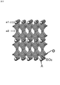
図1は、本実施形態に係る遮熱コーティングの一例を示す概略断面図である。図2は、一般式(2)で表される複合酸化物の構造を示す概略図である。図3は、図1に示した遮熱コーティングを構成する遮熱層を模式的に示す拡大断面図である。図4は、図1に示した遮熱コーティングを構成する第2中間層の一例を示す拡大断面図である。
本実施形態の遮熱コーティング1は、金属結合層11と、金属結合層11の表面に形成された酸化アルミニウム(Al2O3)を主成分とするアルミナ層12と、アルミナ層12上に積層された第1中間層13と、第1中間層13上に積層された第2中間層14と、第2中間層14上に積層された遮熱層15とを備える積層体である。遮熱コーティング1を構成する各層は互いに密着している。遮熱コーティング1は、中間層16として第1中間層13及び第2中間層14を有する。
Hereinafter, embodiments of the present invention will be described with reference to the drawings.
(First Embodiment)
FIG. 1 is a schematic cross-sectional view showing an example of a heat shield coating according to the present embodiment. FIG. 2 is a schematic view showing the structure of the composite oxide represented by the general formula (2). FIG. 3 is an enlarged cross-sectional view schematically showing a heat shield layer constituting the heat shield coating shown in FIG. FIG. 4 is an enlarged cross-sectional view showing an example of the second intermediate layer constituting the heat shield coating shown in FIG.
The
[金属結合層]
金属結合層11は、Alを含む合金からなる層であり、融点が1300℃以上であることが好ましい。
金属結合層11としては、例えば、Fe基合金、Ni基合金、Co基合金、アルミナイド型金属間化合物等を用いることができる。具体的には、例えば、MCrAlY合金(但し、MはNi、Co及びFeの少なくとも1種)、白金アルミナイド、ニッケル−白金−アルミナイド等が挙げられる。
金属結合層11は、他の耐熱基材(図示せず)上に積層されたものであっても良い。
上記他の耐熱基材としては、例えば、Ni、Co、Fe、Nb、Ta、Mo、W、Pt、Ir、Cr及びAl等から選ばれた、少なくとも1種の金属又は少なくとも2種からなる合金が挙げられる。上記他の耐熱基材としては、Ni、Co又はFeを主成分とする超合金等からなるバルク材が好ましい。
[Metal bond layer]
The
As the
The
Examples of the other heat-resistant substrate include at least one metal selected from Ni, Co, Fe, Nb, Ta, Mo, W, Pt, Ir, Cr, Al, and the like, or an alloy composed of at least two. Can be mentioned. As the other heat-resistant base material, a bulk material made of a superalloy containing Ni, Co or Fe as a main component is preferable.
[アルミナ層]
アルミナ層に含まれる酸化アルミニウムは、その結晶相がα−アルミナ、β−アルミナ、γ−アルミナ、σ−アルミナ、χ−アルミナ、η−アルミナ、θ−アルミナ及びκ−アルミナのいずれでも良く、これらのうちの2種以上の組み合わせであっても良い。
アルミナ層12は、高温における安定性、酸素透過防止性等の観点から、α−アルミナからなる層が好ましい。
[Alumina layer]
The crystal phase of aluminum oxide contained in the alumina layer may be any of α-alumina, β-alumina, γ-alumina, σ-alumina, χ-alumina, η-alumina, θ-alumina and κ-alumina. It may be a combination of two or more of them.
The
アルミナ層12は、酸化アルミニウム(Al2O3)のみからなることが好ましいが、本発明の効果が得られる範囲において、NiAl2O4、(Co,Ni)(Al,Cr)2O4等からなる他の化合物を含んでもいても良い。
The
MCrAlY合金(Mは上記と同じ)や白金アルミナイド等からなるAlを含有する金属結合層11を有する遮熱コーティング1は、上述したように高温環境での使用時に金属結合層11の表面にアルミナ層が形成されることが知られている。
そのため、遮熱コーティング1が備えるアルミナ層12は、使用時にAlを含有する金属結合層11の表面に不回避的に生じる層であっても良い。この場合、後述する第2実施形態でも説明するが、製造時にはアルミナ層12を有さない遮熱コーティング1を製造すれば良い。このような遮熱コーティング1では、高温環境での使用過程でアルミナ層が形成されることになる。
As described above, the
Therefore, the
一方、遮熱コーティング1が備えるアルミナ層12は、遮熱コーティング1の製造工程において、金属結合層11に中間層16を積層する前に予め金属結合層11の表面に積極的に設けられた層であっても良い。
この場合、遮熱コーティング1は、製造後・使用前の時点においてアルミナ層12を備えていることになる。
なお、アルミナ層12を金属結合層11の表面に積極的に形成する方法としては、例えば、金属結合層11の表面を酸素含有雰囲気で高温加熱することにより強制酸化する方法があり、金属結合層11の表面にAl拡散処理などを施してAl含有率を増やした後に、酸素含有雰囲気で高温加熱することにより強制酸化する方法が好ましい。一方、物理蒸着法(PVD)、化学蒸着法(CVD)により、金属結合層11の表面に直接にアルミナ層を成膜することでも同様の効果が得られる。
On the other hand, the
In this case, the
As a method of positively forming the
アルミナ層12の厚さは特に限定されないが、遮熱コーティング1を製造する際に、アルミナ層12を金属結合層11の表面に形成する場合は、ヒートサイクル条件下における耐久性等の観点から、好ましくは0.5〜10μm、より好ましくは0.5〜5μm、更に好ましくは0.5〜2μmである。
一方、遮熱コーティング1の使用過程で、金属結合層11の表面に不回避的に形成されるアルミナ層12の厚さは、使用条件等にも依存するため一概には言えないが、好ましくは0.5〜10μm、より好ましくは0.5〜5μm、更に好ましくは0.5〜2μmである。
The thickness of the
On the other hand, the thickness of the
[中間層]
本実施形態に係る遮熱コーティング1を構成する中間層16は、第1中間層13と、第1中間層13上に積層された第2中間層14とを備えている。
<第1中間層>
第1中間層13は、酸化ハフニウム(HfO2)を主成分とする層(以下、ハフニア層ともいう)である。
ハフニア層とアルミナ層とは、両者が接触した状態で1600℃の雰囲気に晒されたとしても、Al2O3がHfO2に固溶しないため、アルミナ層が消失しない。また、金属結合層11中のAl成分が遮熱層15に向かって拡散することもない。そのため、上述したような金属結合層11中のAlが他の層に移行し、枯渇することによって生じる不具合(金属結合層の劣化、各層間の剥離、基材の損傷等)を回避することができる。
第1中間層13は、酸化ハフニウム(HfO2)のみからなることが好ましいが、本発明の効果が得られる範囲において、他の化合物を含んでもいても良い。
[Middle class]
The
<First middle layer>
The first
Even if the Hafnia layer and the alumina layer are exposed to an atmosphere of 1600 ° C. in contact with each other, the alumina layer does not disappear because Al 2 O 3 does not dissolve in HfO 2. Further, the Al component in the
The first
第1中間層13は、気孔率が5体積%以下であることが好ましい。第1中間層13の気孔率を5体積%以下とすることで、貫通した気孔がなくなり、この気孔を通じての急速なAl2O3の固溶や遮熱層側からの腐食物質の侵入透過を防ぐことができる。この場合、高温環境下におけるアルミナ層及び第1中間層の安定性を確保するのに適している。上記気孔率は、3体積%以下であることがより好ましく、この場合、より耐環境性に優れたものとなる。
第1中間層13の気孔率は、皮膜断面を走査型電子顕微鏡(SEM)観察し、気孔が皮膜全体に占める面積を算出した値である。
The first
The porosity of the first
第1中間層13の厚さは特に限定されないが、10〜50μmが好ましい。
第1中間層13の厚さが10μm未満では、Alの移行・拡散を充分に抑制することができないことがある。一方、第1中間層13の厚さが50μmを超えても、Alの移行・拡散を抑制する効果が大きく向上するわけではない。
第1中間層13のより好ましい厚さは、10〜20μmである。
The thickness of the first
If the thickness of the first
A more preferable thickness of the first
<第2中間層>
第2中間層14は、タンタル(Ta)、ハフニウム(Hf)及び酸素(O)からなる化合物、又は、これらの成分に加えて上記一般式(1)中のLnと同一の希土類元素を含む化合物を主成分とする層である。
上記タンタル(Ta)、ハフニウム(Hf)及び酸素(O)からなる化合物は、下記一般式(3)で表される。
TayHfzO(5y+4z)/2
(y=2.0、5.0≦z≦7.0) (3)
上記一般式(3)で表される化合物の具体例としては、例えば、Hf6Ta2O17が挙げられる。
<Second middle layer>
The second
The compound composed of tantalum (Ta), hafnium (Hf) and oxygen (O) is represented by the following general formula (3).
Ta y Hf z O (5y + 4z) / 2
(Y = 2.0, 5.0 ≦ z ≦ 7.0) (3)
Specific examples of the compound represented by the general formula (3) include Hf 6 Ta 2 O 17 .
上記一般式(1)中のLnと同一の希土類元素、タンタル(Ta)、ハフニウム(Hf)及び酸素(O)からなる化合物は、下記一般式(4)又は下記一般式(5)で表される。
LnxTayHfzO(3x+5y+4z)/2
(0<x≦0.25、0<y≦0.25、0.5≦z≦1.0) (4)
LnxTayHfzO(3x+5y+4z)/2
(0.5≦x≦1.0、0.5≦y≦1.0、0<z≦1.0) (5)
第2中間層14は、第1中間層(ハフニア層)13及び遮熱層15の一方又は両方と良好な密着性を有する層である。遮熱コーティング1は、第2中間層14を設けることによって遮熱層15の剥離がより発生しにくくなる。
The compound composed of the same rare earth element as Ln in the general formula (1), tantalum (Ta), hafnium (Hf) and oxygen (O) is represented by the following general formula (4) or the following general formula (5). NS.
Ln x Ta y Hf z O ( 3x + 5y + 4z) / 2
(0 <x ≦ 0.25, 0 <y ≦ 0.25, 0.5 ≦ z ≦ 1.0) (4)
Ln x Ta y Hf z O ( 3x + 5y + 4z) / 2
(0.5 ≦ x ≦ 1.0, 0.5 ≦ y ≦ 1.0, 0 <z ≦ 1.0) (5)
The second
上記一般式(4)で表される化合物は、HfO2にLn、Taが固溶した化合物であり、この化合物を主成分とする層は、特にハフニア層13との密着性に優れる。また、上記一般式(4)で表される化合物は、それ自体が優れた遮熱特性を有している。
上記一般式(5)で表される化合物は、LnTaO4にHfが固溶した化合物であり、この化合物を主成分とする層は、特に遮熱層15との密着性に優れる。また、上記一般式(5)で表される化合物は、それ自体が優れた遮熱特性を有している。
The compound represented by the general formula (4) is a compound in which Ln and Ta are dissolved in HfO 2 , and the layer containing this compound as a main component is particularly excellent in adhesion to the
The compound represented by the general formula (5) is a compound in which Hf is dissolved in LnTaO 4 , and the layer containing this compound as a main component is particularly excellent in adhesion to the
第2中間層14は、図4に示すように、内側第2中間層14b及び外側第2中間層14aの2層で構成されていても良く、その場合には、内側第2中間層14bが上記一般式(4)で表される化合物を主成分とする層であり、外側第2中間層14aが上記一般式(5)で表される化合物を主成分とする層であることが好ましい。
As shown in FIG. 4, the second
また、内側第2中間層14bが上記一般式(4)で表される化合物を主成分とする層であり、外側第2中間層14aが上記一般式(5)で表される化合物を主成分とする層である場合、第2中間層14は、内側第2中間層14bがハフニア層13と良好な密着性を有し、外側第2中間層14aが遮熱層15に含まれる上記一般式(1)で表される複合酸化物と良好な密着性を有し、上記一般式(4)で表される化合物と上記一般式(5)で表される化合物との密着性も良好であるため、第1中間層(ハフニア層)13及び遮熱層15のそれぞれと極めて良好な密着性を有する。
The inner second
第2中間層14の厚さは特に限定されないが、0.2〜30μmが好ましい。
第2中間層14の厚さが0.2μm未満では第1中間層(ハフニア層)13全域を均一に被覆することが困難であり、充分な密着性が得られないことがあり、一方、上記厚さが30μmを超えると新たな熱応力発生の原因となる可能性がある。
また、第2中間層14が外側第2中間層14a及び内側第2中間層14bの2層からなる場合、それぞれ好ましい厚さは0.1〜15μmである。
なお、第2中間層14を構成する化合物は、上記一般式(4)においてx=0及び/又はy=0の化合物であっても良いし、上記一般式(5)においてz=0の化合物であっても良い。
The thickness of the second
If the thickness of the second
When the second
The compound constituting the second
[遮熱層]
遮熱層15は、下記一般式(1)で表される化合物を主成分として含む層である。
LnxTayHfzO(3x+5y+4z)/2 (1)
(式中、Lnは、希土類元素から選ばれた1種の原子である。xは0〜1.0である。yは0.8〜3.0である。zは0〜7.0である。)
上記一般式(1)における原子Lnを表す希土類元素としては、スカンジウム(Sc)、イットリウム(Y)、ランタン(La)、セリウム(Ce)、プラセオジム(Pr)、ネオジム(Nd)、プロメチウム(Pm)、サマリウム(Sm)、ユウロピウム(Eu)、ガドリニウム(Gd)、テルビウム(Tb)、ジスプロシウム(Dy)、ホルミウム(Ho)、エルビウム(Er)、ツリウム(Tm)、イッテルビウム(Yb)及びルテチウム(Lu)が挙げられる。
これらのなかでは、Ybが好ましい。LnがYbである上記一般式(1)で表される化合物は、これらの中でも特に熱伝導率が低い上に、昇降温に伴う相変態がなく、また、その熱伝導率は温度の上昇に伴って徐々に低下する負の温度依存性を有しているからである。
遮熱層15は、上記一般式(1)で表される化合物のみからなることが好ましいが、本発明の効果が得られる範囲において、他の化合物を含んでもいても良い。
[Heat shield layer]
The
Ln x Ta y Hf z O ( 3x + 5y + 4z) / 2 (1)
(In the formula, Ln is one kind of atom selected from rare earth elements. X is 0 to 1.0. Y is 0.8 to 3.0. Z is 0 to 7.0. be.)
Examples of the rare earth element representing the atomic Ln in the general formula (1) include scandium (Sc), yttrium (Y), lanthanum (La), cerium (Ce), placeodim (Pr), neodymium (Nd), and promethium (Pm). , Samarium (Sm), Europium (Eu), Gadrinium (Gd), Terbium (Tb), Dysprosium (Dy), Holmium (Ho), Elbium (Er), Thulium (Tm), Ytterbium (Yb) and Lutetium (Lu) Can be mentioned.
Of these, Yb is preferred. The compound represented by the above general formula (1) in which Ln is Yb has a particularly low thermal conductivity, does not undergo phase transformation due to temperature rise and fall, and its thermal conductivity increases in temperature. This is because it has a negative temperature dependence that gradually decreases with it.
The
上記一般式(1)で表される化合物は、下記一般式(2)で表される化合物である場合、カチオン欠損型の欠陥ペロブスカイト型複合酸化物(以下、「複合酸化物」ともいう。)となり、図2に示すような構造を有する。
LnTa3O9 (2)
(式中、Lnは、希土類元素から選ばれた1種の原子である)
この構造は、A3B3O9で表されるペロブスカイト構造から、a1面で1/3のAイオンが、a2面で全てのAイオンが欠損した構造であり、結晶格子全体として2/3のAイオンが欠損している。
遮熱層15は、上記一般式(2)で表される複合酸化物を含むことで、より低熱伝導性に優れたものとなり、遮熱コーティング1に優れた遮熱性能を付与することができる。
また、上記複合酸化物を含む遮熱層15を備えることによって、遮熱コーティング1に優れた耐食性、耐酸化性及び耐熱性を付与することもできる。
When the compound represented by the general formula (1) is a compound represented by the following general formula (2), it is a cation-deficient defective perovskite-type composite oxide (hereinafter, also referred to as “composite oxide”). It has a structure as shown in FIG.
LnTa 3 O 9 (2)
(In the formula, Ln is one kind of atom selected from rare earth elements)
This structure is a structure in which 1/3 of A ions are deleted on the a1 plane and all A ions are deleted on the a2 plane from the perovskite structure represented by A 3 B 3 O 9, and the entire crystal lattice is 2/3. A ion is deficient.
By containing the composite oxide represented by the general formula (2), the
Further, by providing the
上記一般式(2)で表される複合酸化物の融点は、通常、1700℃以上であり、JIS R 1611に準じて、レーザーフラッシュ法により測定される熱伝導度(測定温度:20℃〜1400℃)は、材料(焼結体)の段階で、通常、3.0W/(m・K)未満である。 The melting point of the composite oxide represented by the general formula (2) is usually 1700 ° C. or higher, and the thermal conductivity (measurement temperature: 20 ° C. to 1400 ° C.) measured by the laser flash method according to JIS R 1611. ° C.) is usually less than 3.0 W / (m · K) at the stage of the material (sintered body).
遮熱層15に含有される上記一般式(1)で表される化合物は、1種のみであって良いし、2種以上であっても良い。ここで、遮熱層15が上記一般式(1)で表される化合物を2種以上含む場合は、少なくとも1つの化合物として上記一般式(2)で表される複合酸化物を含有することが好ましく、上記一般式(2)で表される複合酸化物が主成分であることがより好ましい。また、遮熱層15が上記一般式(2)で表される複合酸化物を2種以上含有する場合、少なくとも1つの上記複合酸化物はYbTa3O9であることが好ましく、その場合は、遮熱層15の主成分は、YbTa3O9であることが好ましい。
また、遮熱層15は、上記一般式(2)で表される複合酸化物のみからなることが好ましい。
The compound represented by the general formula (1) contained in the
Further, the
遮熱層15は、図3に示す模式的な観察像のように、第2中間層14側から最外層側(図中、上側)に延びるように立設された、複数の柱状組織(15a〜15h)からなるセグメント構造を有していることが好ましい。
遮熱層15が、上記セグメント構造を有している場合、隣接する柱状組織同士の間には微小な隙間が存在している。そのため、遮熱コーティング1をヒートサイクル条件下で使用した際に、各層に温度変化に応じた膨張・収縮が発生しても、遮熱層15には各層の膨張・収縮に起因した応力集中が生じにくい。そのため、上記セグメント構造を有する遮熱層15は、ヒートサイクル条件下で特に破損しにくくなる。
The
When the
遮熱層15がセグメント構造を有する場合、遮熱層15の気孔率は、3〜25体積%が好ましい。遮熱層15の気孔率が3体積%未満では気孔の存在による低熱伝導率化が充分に発揮できずに必要とされる遮熱特性を得られないことがある。一方、上記気孔率が25体積%を超えると、気孔の存在による低熱伝導率化が充分に発揮されて遮熱特性には優れるものの、燃焼ガスなどに含まれる粒子状物質などによるエロージョン性への耐性が得られないことがある。上記気孔率は、5〜20体積%がより好ましい。
遮熱層15の気孔率は、皮膜断面を走査型電子顕微鏡(SEM)観察し、気孔が皮膜全体に占める面積を算出した値である。
When the
The porosity of the
遮熱層15がセグメント構造を有している場合、当該セグメント構造を構成する柱状組織の個数(セグメント数)は、単位長さ当たりのセグメント数で5〜30個/mmであることが好ましい。
上記単位長さ当たりのセグメント数が5個/mm未満では、ヒートサイクル条件下での破損等を回避する効果を充分に享受できないことがある。一方、上記セグメント数が30個/mmを超えると、燃焼ガスの侵入による下地層の劣化が起こることがある。
When the
If the number of segments per unit length is less than 5 / mm, the effect of avoiding damage under heat cycle conditions may not be fully enjoyed. On the other hand, if the number of the segments exceeds 30 / mm, the underlayer may be deteriorated due to the intrusion of combustion gas.
上記単位長さ当たりのセグメント数(個/mm)は、下記の方法にて算出した値である。
まず、遮熱層15の厚さ方向に沿った断面の画像(図3参照)を取得し、得られた画像の遮熱層15の厚さの1/2の位置に、遮熱層15の直下の層(図3では、第2中間層14)の表面に平行な仮想基準線(図3中、一点鎖線)BLを描く。その後、この仮想基準線BLによって横切られる柱状組織の個数をカウントし、1mmの仮想基準線BLによって横切られる柱状組織の個数を、単位長さ当たりのセグメント数(個/mm)として算出する。
このとき、単位長さ当たりのセグメント数(個/mm)は、少なくとも合計10mmの仮想基準線を用いて算出する。
なお、図3の例では合計8個(図中、◆印参照)の柱状組織15a〜15hが存在している。
The number of segments (pieces / mm) per unit length is a value calculated by the following method.
First, an image of a cross section along the thickness direction of the heat shield layer 15 (see FIG. 3) is acquired, and the
At this time, the number of segments (pieces / mm) per unit length is calculated using a virtual reference line having a total of at least 10 mm.
In the example of FIG. 3, a total of eight
遮熱層15の厚さは特に限定されないが、低熱伝導性及び耐久性、更には耐食性、耐酸化性、耐熱性、金属結合層の保護効果等の性質の観点から、100〜2000μmが好ましい。
遮熱層15のより好ましい厚さは、200〜500μmである。
The thickness of the
A more preferable thickness of the
本実施形態の遮熱コーティング1は、各層を金属結合層11側から順に積層していくことにより製造することができる。
例えば、Ni基超合金、Co基超合金、Fe基超合金等からなる耐熱基材の表面に、各層の皮膜を順に積層すれば良い。
上記皮膜の形成において、金属結合層11、第1中間層13及び第2中間層14は、例えば、電子ビーム物理蒸着(EB−PVD)、大気圧プラズマ溶射、減圧プラズマ溶射、サスペンション溶射(サスペンションプラズマ溶射、サスペンション高速フレーム溶射等)、高速フレーム溶射、焼結等の方法で製造すれば良い。
より具体的には、以下の通りである。
金属結合層11は、大気圧プラズマ溶射、減圧プラズマ溶射、高速フレーム溶射、又はEB−PVDによって形成することが好ましい。
第1中間層13は、サスペンション溶射、大気圧プラズマ溶射、減圧プラズマ溶射、又はEB−PVDによって形成することが好ましい。
第2中間層14は、サスペンション溶射、大気圧プラズマ溶射、減圧プラズマ溶射、又はEB−PVDによって形成することが好ましい。
また、アルミナ層12は、上述した通り、金属結合層11の表面に積極的に形成しても良いし、使用過程で不回避的に形成しても良い。
The
For example, the coatings of each layer may be laminated in order on the surface of a heat-resistant base material made of a Ni-based superalloy, a Co-based superalloy, an Fe-based superalloy, or the like.
In the formation of the above film, the
More specifically, it is as follows.
The
The first
The second
Further, as described above, the
遮熱層15は、上記一般式(1)で表される化合物を、電子ビーム物理蒸着(EB−PVD)、大気圧プラズマ溶射、減圧プラズマ溶射、サスペンション溶射、焼結等の方法で形成すれば良い。
If the
上記一般式(2)で表される複合酸化物の製造方法は、上記一般式(2)における原子Lnを構成する希土類元素を含む化合物(以下、「化合物(m1)」という。)と、Taを含む化合物(以下、「化合物(m2)」という。)とを、原子Ln及びTaのモル比が所定の割合となるように配合し、これを熱処理する方法が一般的である。
更に、より均質な複合酸化物を得るために、例えば、尿素を含む混合物とした後、これを熱処理する方法を採用しても良い。
The method for producing the composite oxide represented by the general formula (2) is a compound containing a rare earth element constituting the atomic Ln in the general formula (2) (hereinafter, referred to as “compound (m1)”) and Ta. In general, a compound containing (hereinafter referred to as "compound (m2)") is blended so that the molar ratio of atoms Ln and Ta is a predetermined ratio, and the compound is heat-treated.
Further, in order to obtain a more homogeneous composite oxide, for example, a method may be adopted in which a mixture containing urea is prepared and then heat-treated.
上記化合物(m1)及び化合物(m2)としては、酸化物、水酸化物、硫酸塩、炭酸塩、硝酸塩、リン酸塩、ハロゲン化物等を用いることができる。これらのうち、組成がより均一な複合酸化物を得る場合には、水溶性化合物が好ましいが、水不溶性化合物を用いることもできる。 As the compound (m1) and the compound (m2), oxides, hydroxides, sulfates, carbonates, nitrates, phosphates, halides and the like can be used. Of these, when a composite oxide having a more uniform composition is obtained, a water-soluble compound is preferable, but a water-insoluble compound can also be used.
上記複合酸化物の好ましい製造方法は、以下の通りである。
初めに、原子Ln及びTaのモル比が1:3となるように配合した、化合物(m1)及び化合物(m2)と、尿素とを含む水溶液又は水分散液(懸濁液)を調製する。化合物(m1)の濃度は、好ましくは0.02〜0.1mol/l、より好ましくは0.02〜0.05mol/lである。化合物(m2)の濃度は、好ましくは0.02〜0.1mol/l、より好ましくは0.02〜0.05mol/lである。尿素の濃度は、好ましくは2〜10mol/l、より好ましくは2〜5mol/lである。
次に、混合液を、還流冷却下、80℃〜95℃の温度で加熱して尿素加水分解反応を行う。反応時間は、通常、10〜20時間である。
その後、反応系に含まれる反応生成物の形態によって、必要に応じて、遠心分離等を行い、反応生成物を回収する。そして、水、アルコール等を用いて洗浄し、乾燥させ、必要に応じて、粉砕することにより、第1前駆化合物からなる粉体を得る。
次に、第1前駆化合物からなる粉体を整粒し、必要に応じて、プレス成形等に供して、板状、塊状等の成形物を作製する。そして、この成形物を、酸素ガスを含む雰囲気下、1200℃〜1500℃の温度で、1〜3時間程度の熱処理(仮焼)を行い、仮焼物を得る。その後、得られた仮焼物を、必要に応じて、粉砕、整粒する。そして、必要に応じて、プレス成形等に供して、板状、塊状等の成形物を作製し、この成形物を、酸素ガスを含む雰囲気下、1400℃〜1700℃の温度で、1〜3時間程度の熱処理を行い、上記一般式(2)で表される複合酸化物を得る。
The preferred method for producing the composite oxide is as follows.
First, an aqueous solution or an aqueous dispersion (suspension) containing the compound (m1) and the compound (m2) and urea, which are blended so that the molar ratio of atoms Ln and Ta is 1: 3, is prepared. The concentration of compound (m1) is preferably 0.02 to 0.1 mol / l, more preferably 0.02 to 0.05 mol / l. The concentration of compound (m2) is preferably 0.02 to 0.1 mol / l, more preferably 0.02 to 0.05 mol / l. The concentration of urea is preferably 2 to 10 mol / l, more preferably 2 to 5 mol / l.
Next, the mixed solution is heated under reflux cooling at a temperature of 80 ° C. to 95 ° C. to carry out a urea hydrolysis reaction. The reaction time is usually 10 to 20 hours.
Then, depending on the form of the reaction product contained in the reaction system, if necessary, centrifugation or the like is performed to recover the reaction product. Then, it is washed with water, alcohol or the like, dried, and if necessary, pulverized to obtain a powder composed of the first precursor compound.
Next, the powder made of the first precursor compound is sized and, if necessary, subjected to press molding or the like to prepare a plate-shaped or lump-shaped molded product. Then, this molded product is heat-treated (temporarily baked) for about 1 to 3 hours at a temperature of 1200 ° C. to 1500 ° C. in an atmosphere containing oxygen gas to obtain a calcined product. Then, the obtained calcined product is crushed and sized as necessary. Then, if necessary, it is subjected to press molding or the like to prepare a plate-shaped or lump-shaped molded product, and the molded product is subjected to 1 to 3 at a temperature of 1400 ° C. to 1700 ° C. in an atmosphere containing oxygen gas. Heat treatment is carried out for about an hour to obtain a composite oxide represented by the above general formula (2).
遮熱層15を形成する方法としては、平均粒子径0.05〜5μmの上記一般式(1)で表される化合物や上記一般式(2)で表される化合物を含む材料を用いて、サスペンション溶射する方法が好ましい。この方法は、セグメント構造を有する遮熱層15を形成する方法として適している。
上記サスペンション溶射によって、セグメント構造を有する遮熱層15を形成する場合、上記セグメント構造における気孔率や、単位長さ当たりのセグメントの個数は、溶射条件である入熱量、溶射距離、トラバース速度、及びピッチを変更することで制御することができる。
As a method for forming the
When the
(第2実施形態)
図5は、本実施形態に係る遮熱コーティングの一例を示す概略断面図である。
本実施形態に係る遮熱コーティングは、アルミナ層を設けることなく製造した遮熱コーティングであり、図5に示すように、金属結合層21と、金属結合層21の表面に積層された中間層26(第1中間層23及び第2中間層24)と、第2中間層24上に積層された遮熱層25とを備える遮熱コーティング2である。
遮熱コーティング2における金属結合層21、第1中間層23、第2中間層24及び遮熱層25の構成は、第1実施形態の遮熱コーティング1と同様である。
(Second Embodiment)
FIG. 5 is a schematic cross-sectional view showing an example of the heat shield coating according to the present embodiment.
The thermal barrier coating according to the present embodiment is a thermal barrier coating produced without providing an alumina layer, and as shown in FIG. 5, the
The structure of the
このような層構成の遮熱コーティング2は、未使用の遮熱コーティング2であり、遮熱コーティング2を使用した際には使用時間の経過とともに、金属結合層21の第1中間層23側に徐々にアルミナ層が形成され、第1実施形態の遮熱コーティング1と同様の層構成となる。
このような、未使用時にはアルミナ層が無く、使用時間の経過とともにアルミナ層が形成される遮熱コーティングも本発明の実施形態の1つである。
The
Such a heat-shielding coating that does not have an alumina layer when not in use and forms an alumina layer with the passage of time is also one of the embodiments of the present invention.
(第3実施形態)
本発明の実施形態に係る遮熱コーティングは、中間層として、酸化ハフニウム(HfO2)を主成分とする層のみが設けられていても良い。
この場合、金属結合層(又は、アルミナ層)上に、直接、酸化ハフニウム(HfO2)を主成分とする層が形成され、更に、このハフニア層上に直接、遮熱層が形成されていることになる。
(Third Embodiment)
The heat shield coating according to the embodiment of the present invention may be provided with only a layer containing hafnium oxide (HfO 2) as a main component as an intermediate layer.
In this case, a layer containing hafnium oxide (HfO 2 ) as a main component is directly formed on the metal bonding layer (or alumina layer), and a heat shield layer is directly formed on the hafnium layer. It will be.
(第4実施形態)
本発明の実施形態に係る遮熱コーティングは、中間層として、タンタル(Ta)、ハフニウム(Hf)及び酸素(O)からなる化合物を主成分とする層のみが設けられていても良い。
この場合、金属結合層(又は、アルミナ層)上に、直接、タンタル(Ta)、ハフニウム(Hf)及び酸素(O)からなる化合物を主成分とする層が形成され、更に、この中間層上に直接、遮熱層が形成されていることになる。
ここで、タンタル(Ta)、ハフニウム(Hf)及び酸素(O)からなる化合物の具体例としては、上記一般式(3)で表される化合物が挙げられる。
(Fourth Embodiment)
The heat shield coating according to the embodiment of the present invention may be provided with only a layer containing only a compound composed of tantalum (Ta), hafnium (Hf) and oxygen (O) as a main component as an intermediate layer.
In this case, a layer mainly composed of a compound composed of tantalum (Ta), hafnium (Hf) and oxygen (O) is directly formed on the metal bonding layer (or alumina layer), and further on the intermediate layer. The heat shield layer is directly formed on the surface.
Here, specific examples of the compound composed of tantalum (Ta), hafnium (Hf) and oxygen (O) include the compound represented by the above general formula (3).
(第5実施形態)
本発明の実施形態に係る遮熱コーティングは、中間層として、希土類元素、タンタル(Ta)、ハフニウム(Hf)及び酸素(O)からなる化合物を主成分とする層のみが設けられていても良い。
この場合、金属結合層(又は、アルミナ層)上に、直接、希土類元素、タンタル(Ta)、ハフニウム(Hf)及び酸素(O)からなる化合物を主成分とする層が形成され、更に、この中間層上に直接、遮熱層が形成されていることになる。
ここで、上記希土類元素は、上記一般式(1)中のLnと同一の希土類元素であることが好ましい。また、希土類元素、タンタル(Ta)、ハフニウム(Hf)及び酸素(O)からなる化合物の具体例としては、上記一般式(4)で表される化合物、及び上記一般式(5)で表される化合物が挙げられる。
(Fifth Embodiment)
The heat shield coating according to the embodiment of the present invention may be provided with only a layer containing a compound composed of a rare earth element, tantalum (Ta), hafnium (Hf) and oxygen (O) as a main component as an intermediate layer. ..
In this case, a layer mainly composed of a compound composed of a rare earth element, tantalum (Ta), hafnium (Hf) and oxygen (O) is directly formed on the metal bonding layer (or alumina layer), and further, this layer is formed. The heat shield layer is formed directly on the intermediate layer.
Here, the rare earth element is preferably the same rare earth element as Ln in the general formula (1). Specific examples of the compound composed of a rare earth element, tantalum (Ta), hafnium (Hf) and oxygen (O) include the compound represented by the general formula (4) and the general formula (5). Compounds include.
(その他の実施形態)
上記第1実施形態及び第2実施形態において、遮熱コーティングを構成する中間層は、タンタル(Ta)、ハフニウム(Hf)及び酸素(O)からなる化合物を主成分とする第1中間層と、タンタル(Ta)、ハフニウム(Hf)及び酸素(O)に加えて上記一般式(1)中のLnと同一の希土類元素を含む化合物を主成分とする第2中間層と、で構成されていても良い。
(Other embodiments)
In the first and second embodiments, the intermediate layer constituting the heat-shielding coating includes a first intermediate layer containing a compound composed of tantalum (Ta), hafnium (Hf) and oxygen (O) as a main component. It is composed of a second intermediate layer whose main component is a compound containing the same rare earth element as Ln in the above general formula (1) in addition to tantalum (Ta), hafnium (Hf) and oxygen (O). Is also good.
上記第1実施形態及び第2実施形態において、第2中間層に含まれるタンタル(Ta)、ハフニウム(Hf)及び酸素(O)からなる化合物、並びに、これらの成分に加えて一般式(1)中のLnと同一の希土類元素を含む化合物は、それぞれ第1中間層側から遮熱層側に向かって徐々に組成比が変化するものであって良い。 In the first embodiment and the second embodiment, the compound composed of tantalum (Ta), hafnium (Hf) and oxygen (O) contained in the second intermediate layer, and the general formula (1) in addition to these components. Each of the compounds containing the same rare earth element as Ln may have a composition ratio that gradually changes from the first mesosphere side to the heat shield layer side.
上記一般式(4)及び上記一般式(5)で表される化合物は、それ自体が優れた遮熱特性を有しているため、遮熱層として用いることもできる。この場合、上記遮熱層は、上記一般式(4)で表される化合物、又は上記一般式(5)で表される化合物を主成分として含んでいても良く、上記一般式(4)で表される化合物、又は上記一般式(5)で表される化合物のみからなるものであっても良い。 Since the compounds represented by the general formula (4) and the general formula (5) themselves have excellent heat-shielding properties, they can also be used as a heat-shielding layer. In this case, the heat shield layer may contain the compound represented by the general formula (4) or the compound represented by the general formula (5) as a main component, and the general formula (4) may be used. It may consist only of the compound represented by the above-mentioned compound or the compound represented by the above general formula (5).
本発明の実施形態に係る遮熱コーティングは、例えば、航空機用ジェットエンジンや発電用ガスタービンにおける動翼等の高温部品、その他、自動車などの各種エンジンや各種プラントにおける高温部品などとして好適に使用することができる。
上記遮熱コーティングが航空機用ジェットエンジンにおける燃焼器等の高温部品である場合には、作動温度をより高温化して燃費の向上を図ることができる。
また、上記遮熱コーティングが発電用ガスタービンにおける動翼等の高温部品である場合には、作動温度をより高温化して発電効率の向上を図ることができる。
The heat shield coating according to the embodiment of the present invention is suitably used as, for example, high temperature parts such as moving blades in an aircraft jet engine and a gas turbine for power generation, and other high temperature parts in various engines such as automobiles and various plants. be able to.
When the heat-shielding coating is a high-temperature component such as a combustor in an aircraft jet engine, the operating temperature can be raised to improve fuel efficiency.
Further, when the heat shield coating is a high temperature component such as a moving blade in a gas turbine for power generation, the operating temperature can be further increased to improve the power generation efficiency.
(評価試験)
本発明の実施形態に係る遮熱コーティングの性能を確認するために、下記の評価試験を行った。
[評価試験1]
本発明の実施形態に係る遮熱コーティングにおいて中間層を構成する化合物の1つであるHf6Ta2O17について、熱伝導性能を評価した。
(Evaluation test)
In order to confirm the performance of the thermal barrier coating according to the embodiment of the present invention, the following evaluation test was conducted.
[Evaluation test 1]
The heat conduction performance of Hf 6 Ta 2 O 17 , which is one of the compounds constituting the intermediate layer in the heat shield coating according to the embodiment of the present invention, was evaluated.
(1)評価サンプル(Hf6Ta2O17)の作製
フッ素樹脂製の反応器に収容した蒸留水773グラムに、純度99.9%以上のHfCl4粉末(和光純薬)25グラム(0.078モル)を入れて、室温(25℃)で1時間撹拌し、無色透明の水溶液を得た。次いで、この水溶液に、尿素586グラム(9.8モル)を投入し、室温(25℃)で1時間撹拌した。その後、得られた無色透明の水溶液に、純度99.9%以上のTa2O5粉末(レアメタリック社製)6グラム(0.014モル)を投入し、室温(25℃)で7時間撹拌し、懸濁液を得た。
次に、懸濁液を加熱して95℃とし、還流冷却しながら、攪拌下、反応(尿素加水分解反応)させた(反応時間:14時間)。その後、得られた反応液を、25℃、4800rpmで30分間遠心分離し、下層のゲルを回収した。このゲルを、大量の蒸留水に投入し、十分に撹拌したところで、上記と同じ条件で遠心分離し、下層のゲルを回収した。
その後、沈殿物を、大気雰囲気中、1700℃で1時間加熱し、アルミナ乳鉢で粉砕し、ふるい(100メッシュ)にかけて、微粉末を回収した。
この微粉末を、プレス成形(圧力25MPa)に供した。その後、この成形体をホットプレス(40MPa、Ar雰囲気)により、1600℃で2時間熱処理した。得られた焼成体を、室温(25℃)で、乳鉢により乾式粉砕し、そのX線回折測定を行い、Hf6Ta2O17からなる直方晶系であることを確認した。密度ρは10.4g/cm3であった。
(1) Preparation of evaluation sample (Hf 6 Ta 2 O 17 ) 25 grams (0.078) of HfCl4 powder (Wako Pure Chemical Industries, Ltd.) having a purity of 99.9% or more was added to 773 grams of distilled water contained in a fluororesin reactor. Mol) was added and stirred at room temperature (25 ° C.) for 1 hour to obtain a colorless and transparent aqueous solution. Then, 586 grams (9.8 mol) of urea was added to this aqueous solution, and the mixture was stirred at room temperature (25 ° C.) for 1 hour. Then, 6 grams (0.014 mol) of Ta 2 O 5 powder (manufactured by Rare Metallic) having a purity of 99.9% or more was added to the obtained colorless and transparent aqueous solution, and the mixture was stirred at room temperature (25 ° C.) for 7 hours. And obtained a suspension.
Next, the suspension was heated to 95 ° C., and the reaction (urea hydrolysis reaction) was carried out under stirring while reflux cooling (reaction time: 14 hours). Then, the obtained reaction solution was centrifuged at 25 ° C. and 4800 rpm for 30 minutes, and the gel in the lower layer was recovered. When this gel was put into a large amount of distilled water and sufficiently stirred, it was centrifuged under the same conditions as above, and the gel in the lower layer was recovered.
Then, the precipitate was heated in an air atmosphere at 1700 ° C. for 1 hour, pulverized in an alumina mortar, and sieved (100 mesh) to recover fine powder.
This fine powder was subjected to press molding (
(2)比較サンプル(7wt%Y2O3-ZrO2)の作製
7wt%Y2O3-ZrO2粉末(東ソー、TZ−4YS)を、プレス成形(圧力25MPa)に供した。その後、この成形体を大気雰囲気中、1500℃で5時間熱処理した。密度ρは9.91g/cm3であった。
(2) Preparation of Comparative Sample (7 wt% Y 2 O 3 -ZrO 2 ) 7 wt% Y 2 O 3 -ZrO 2 powder (Tosoh, TZ-4YS) was subjected to press molding (
(3)熱伝導率の測定
評価サンプル(Hf6Ta2O17)及び比較サンプル(7wt%Y2O3-ZrO2)のそれぞれを、レーザーフラッシュ法(JIS R 1611に準拠)に供して、25℃、100℃、200℃、300℃、400℃、500℃、600℃、700℃、800℃、900℃及び1000℃における熱伝導率を測定した。
なお、固体の熱伝導率は気孔の影響を受け、気孔を含むと低めの値となるため、下記式(7)に示す補正式(参照文献:C. Wan, et al., Acta Mater., 58, 6166−6172 (2010))を用いて補正した。
k’/k=1−4/3φ (7)
(式中、k’は供試体の熱伝導率、kは緻密質としての熱伝導率、φは気孔率である。)
ここでは、熱伝導率の測定値を上記式(7)を用いて補正し、補正された熱伝導率を評価値とした。
図6は、本評価試験1の結果を示すグラフであり、熱伝導率の温度依存性を示す。
図6に示したように、Hf6Ta2O17の熱伝導率は、室温から1300℃の高温まで、終始YSZに比べて低い値を示すことが明らかとなった。
(3) Measurement of thermal conductivity Each of the evaluation sample (Hf 6 Ta 2 O 17 ) and the comparative sample (7 wt% Y 2 O 3 -ZrO 2 ) was subjected to a laser flash method (based on JIS R 1611). Thermal conductivity at 25 ° C., 100 ° C., 200 ° C., 300 ° C., 400 ° C., 500 ° C., 600 ° C., 700 ° C., 800 ° C., 900 ° C. and 1000 ° C. was measured.
Since the thermal conductivity of a solid is affected by pores and becomes a low value when pores are included, the correction formula shown in the following formula (7) (reference: C. Wan, et al., Acta Mater., 58, 6166-6172 (2010)) was used for correction.
k'/ k = 1-4 / 3φ (7)
(In the formula, k'is the thermal conductivity of the specimen, k is the thermal conductivity as a dense substance, and φ is the porosity.)
Here, the measured value of thermal conductivity was corrected using the above equation (7), and the corrected thermal conductivity was used as the evaluation value.
FIG. 6 is a graph showing the results of this
As shown in FIG. 6, it was clarified that the thermal conductivity of Hf 6 Ta 2 O 17 was lower than that of YSZ from room temperature to a high temperature of 1300 ° C. from beginning to end.
[評価試験2]
本発明の実施形態に係る遮熱コーティングにおいて中間層を構成しえる化合物であるHf6Ta2O17及びHfO2(ハフニア)の屈折率を測定した。また、比較サンプルとして、Al2O3(アルミナ)の屈折率を測定した。
(1)評価サンプルの作製
(1−1)Hf6Ta2O17の焼結体:
評価試験1と同様にして評価サンプルを作製した。
(1−2)HfO2の焼結体:
HfO2粉末(99.99%以上、EMジャパン)を、プレス成形(圧力25MPa)に供した。その後、この成形体を大気雰囲気中、1600℃で5時間熱処理し、焼結体を作製した。密度ρは9.91g/cm3であった。
(2)比較サンプルの作製
Al2O3の焼結体:
Al2O3粉末(99.9999%以上、大明化学工業)を、プレス成形(圧力25MPa)に供した。その後、この成形体を大気雰囲気中、1500℃で5時間熱処理し、焼結体を作製した。密度ρは3.97g/cm3であった。
[Evaluation test 2]
The refractive indexes of Hf 6 Ta 2 O 17 and Hf O 2 (hafnium), which are compounds that can form an intermediate layer in the heat shield coating according to the embodiment of the present invention, were measured. Moreover, as a comparative sample, the refractive index of Al 2 O 3 (alumina) was measured.
(1) Preparation of evaluation sample (1-1) Sintered body of Hf 6 Ta 2 O 17:
An evaluation sample was prepared in the same manner as in the
(1-2) HfO 2 sintered body:
HfO 2 powder (99.99% or more, EM Japan) was subjected to press molding (
(2) Preparation of comparative sample Al 2 O 3 sintered body:
Al 2 O 3 powder (99.9999% or more, Daimei Chemical Industry Co., Ltd.) was subjected to press molding (
(3)屈折率の測定
分光エリプソメーター(堀場製作所製、商品名:UVISEL)を用い、波長範囲を500〜2000nmとして、各サンプルにおける屈折率を測定した。
図7は、本評価試験の結果を示すグラフであり、屈折率の波長依存性を示す。
図7に示したように、Hf6Ta2O17およびHfO2の屈折率は、500〜2000nmの波長範囲において、終始Al2O3に比べて高い値を示すことが明らかとなった。
このことから、Al2O3層上に、HfO2層又はHf6Ta2O17層を設けることにより、Al2O3層とHfO2層又はHf6Ta2O17層との層間に大きな屈折率差が形成され、外部から入射する熱エネルギーを効果的に反射することができると考えられた。
(3) Measurement of Refractive Index Using a spectroscopic ellipsometer (manufactured by HORIBA, Ltd., trade name: UVISEL), the refractive index of each sample was measured with a wavelength range of 500 to 2000 nm.
FIG. 7 is a graph showing the results of this evaluation test, showing the wavelength dependence of the refractive index.
As shown in FIG. 7, it was revealed that the refractive indexes of Hf 6 Ta 2 O 17 and Hf O 2 are higher than those of Al 2 O 3 from beginning to end in the wavelength range of 500 to 2000 nm.
Large Therefore, in the Al 2 O 3 layer on the interlayer and by providing a HfO 2 layer or Hf 6 Ta 2 O 17 layer, the Al 2 O 3 layer and the HfO 2 layer or Hf 6 Ta 2 O 17 layer It was considered that a difference in refractive index was formed and the thermal energy incident from the outside could be effectively reflected.
[評価試験3]
HfO2層と、Hf6Ta2O17層との界面安定性を予想するために、本評価試験3を行った。
HfO2粉末及びHf6Ta2O17粉末を、体積分率が等しくなるように、それぞれ49.2wt%及び50.8wt%の組成にて配合し、乳鉢を用いて混合した。
本評価試験3に用いたHfO2粉末及びHf6Ta2O17粉末は、上記評価試験2で用いた焼結用粉末と同一とした。
この混合粉末をプレス成形(圧力25MPa)後、大気雰囲気中、1400℃で20時間熱処理した。
[Evaluation test 3]
This
HfO 2 powder and Hf 6 Ta 2 O 17 powder were blended in compositions of 49.2 wt% and 50.8 wt%, respectively, so that the volume fractions were equal, and mixed using a mortar.
The HfO 2 powder and the Hf 6 Ta 2 O 17 powder used in this
This mixed powder was press-molded (
熱処理前の混合粉末及び熱処理後の焼結体についてX線回折を行った。結果を図8に示した。
図8は、本評価試験で得られたX線回折図形である。
図8に示すように、熱処理前の混合粉末及び熱処理後の焼結体共に、HfO2及びHf6Ta2O17の回折線のみが検出され、HfO2及びHf6Ta2O17との間において、なんら反応が進行していないことが確認された。
X-ray diffraction was performed on the mixed powder before the heat treatment and the sintered body after the heat treatment. The results are shown in FIG.
FIG. 8 is an X-ray diffraction pattern obtained in this evaluation test.
As shown in FIG. 8, only the diffraction lines of HfO 2 and Hf 6 Ta 2 O 17 were detected in both the mixed powder before the heat treatment and the sintered body after the heat treatment, and between HfO 2 and Hf 6 Ta 2 O 17. It was confirmed that no reaction was progressing.
[評価試験4]
Al2O3層とHf6Ta2O17層との界面安定性を予想するために、本評価試験4を行った。
Al2O3粉末及びHf6Ta2O17粉末を、体積分率が等しくなるように、それぞれ27.7wt%及び72.3wt%の組成にて配合し、乳鉢を用いて混合した。
本評価試験4に用いたAl2O3粉末及びHf6Ta2O17粉末は、上記評価試験2で用いた焼結用粉末と同一とした。
この混合粉末をプレス成形(圧力25MPa)後、大気雰囲気中、1400℃で20時間熱処理した。
[Evaluation test 4]
This evaluation test 4 was conducted in order to predict the interfacial stability between the Al 2 O 3 layer and the Hf 6 Ta 2 O 17 layer.
Al 2 O 3 powder and Hf 6 Ta 2 O 17 powder were blended in compositions of 27.7 wt% and 72.3 wt%, respectively, so that the volume fractions were equal, and mixed using a mortar.
The Al 2 O 3 powder and the Hf 6 Ta 2 O 17 powder used in the evaluation test 4 were the same as the sintering powder used in the
This mixed powder was press-molded (
熱処理前の混合粉末及び熱処理後の焼結体についてX線回折を行った。結果を図9に示した。
図9は、本評価試験で得られたX線回折図形である。
図9に示すように、熱処理前の混合粉末及び熱処理後の焼結体共に、Al2O3及びHf6Ta2O17の回折線のみが検出され、Al2O3及びHf6Ta2O17との間において、なんら反応が進行していないことが確認された。
X-ray diffraction was performed on the mixed powder before the heat treatment and the sintered body after the heat treatment. The results are shown in FIG.
FIG. 9 is an X-ray diffraction pattern obtained in this evaluation test.
As shown in FIG. 9, the sintered body after the mixed powder and heat treatment prior to the heat treatment together, only the diffraction line of Al 2 O 3 and Hf 6 Ta 2 O 17 is detected, Al 2 O 3 and Hf 6 Ta 2 O It was confirmed that no reaction was progressing with 17.
[評価試験5]
Hf6Ta2O17層とYTa3O9層との界面安定性を予想するために、本評価試験5を行った。
Hf6Ta2O17粉末及びYTa3O9粉末を、体積分率が等しくなるように、それぞれ58.0wt%及び42.0wt%の組成にて配合し、乳鉢を用いて混合した。
この混合粉末をプレス成形(圧力25MPa)後、大気雰囲気中、1400℃で20時間熱処理した。
[Evaluation test 5]
This evaluation test 5 was conducted in order to predict the interfacial stability between the Hf 6 Ta 2 O 17 layer and the Y Ta 3 O 9 layer.
Hf 6 Ta 2 O 17 powder and Y Ta 3 O 9 powder were blended in compositions of 58.0 wt% and 42.0 wt%, respectively, so that the volume fractions were equal, and mixed using a mortar.
This mixed powder was press-molded (
本評価試験5に用いたHf6Ta2O17粉末は、上記評価試験1で用いた焼結用粉末と同一とした。
一方、YTa3O9粉末は以下の手順で作製した。
フッ素樹脂製の反応器に収容した蒸留水713グラムに、純度99.99%以上のY(NO3)3・6H2O粉末(関東化学社製)28グラム(0.072モル)を入れて、室温(25℃)で1時間撹拌し、無色透明の水溶液を得た。
次いで、この水溶液に、尿素540グラム(9モル)を投入し、室温(25℃)で1時間撹拌した。その後、得られた無色透明の水溶液に、純度99.9%以上のTa2O5粉末(レアメタリック社製)50グラム(0.113モル)を投入し、室温(25℃)で7時間撹拌し、懸濁液を得た。
次に、懸濁液を加熱して95℃とし、還流冷却しながら、攪拌下、反応(尿素加水分解反応)させた(反応時間:14時間)。その後、得られた反応液を、25℃、4800rpmで30分間遠心分離し、下層のゲルを回収した。このゲルを、大量の蒸留水に投入し、十分に撹拌したところで、上記と同じ条件で遠心分離し、下層のゲルを回収した。
その後、沈殿物を、大気雰囲気中、120℃で14時間加熱し、乾燥粉末とした。次いで、この乾燥粉末をふるい(100メッシュ)にかけて、微粉末を回収した。この微粉末を、プレス成形(圧力25MPa)後、大気雰囲気中、1700℃で1時間熱処理した。得られたサンプルを、室温で乳鉢により乾式粉砕し、微粉末を得た。そのX線回折測定を行い、YTa3O9からなる直方晶系であることを確認した。
The Hf 6 Ta 2 O 17 powder used in this evaluation test 5 was the same as the sintering powder used in the
On the other hand, YTa 3 O 9 powder was prepared by the following procedure.
Distilled water 713 g were housed in a fluororesin-made reactor, purity of 99.99% or higher Y (NO 3) 3 · 6H ( Kanto Chemical) 2 O powder put 28 grams (0.072 moles) , Stirred at room temperature (25 ° C.) for 1 hour to obtain a colorless and transparent aqueous solution.
Next, 540 grams (9 mol) of urea was added to this aqueous solution, and the mixture was stirred at room temperature (25 ° C.) for 1 hour. Then, 50 grams (0.113 mol) of Ta 2 O 5 powder (manufactured by Rare Metallic) having a purity of 99.9% or more was added to the obtained colorless and transparent aqueous solution, and the mixture was stirred at room temperature (25 ° C.) for 7 hours. And obtained a suspension.
Next, the suspension was heated to 95 ° C., and the reaction (urea hydrolysis reaction) was carried out under stirring while reflux cooling (reaction time: 14 hours). Then, the obtained reaction solution was centrifuged at 25 ° C. and 4800 rpm for 30 minutes, and the gel in the lower layer was recovered. When this gel was put into a large amount of distilled water and sufficiently stirred, it was centrifuged under the same conditions as above, and the gel in the lower layer was recovered.
Then, the precipitate was heated at 120 ° C. for 14 hours in an air atmosphere to obtain a dry powder. The dry powder was then sieved (100 mesh) to recover the fine powder. This fine powder was press-molded (
熱処理前の混合粉末及び熱処理後の焼結体についてX線回折を行った。結果を図10に示した。
図10は、本評価試験で得られたX線回折図形である。
図10に示した通り、熱処理に伴う異相の生成はごくわずかであり、Hf6Ta2O17とYTa3O9との間における反応は軽微であることが確認された。
X-ray diffraction was performed on the mixed powder before the heat treatment and the sintered body after the heat treatment. The results are shown in FIG.
FIG. 10 is an X-ray diffraction pattern obtained in this evaluation test.
As shown in FIG. 10, it was confirmed that the formation of different phases due to the heat treatment was negligible, and the reaction between Hf 6 Ta 2 O 17 and Y Ta 3 O 9 was slight.
[評価試験6]
Al2O3層とYTa3O9層との界面安定性を予想するために、本評価試験6を行った。
Al2O3粉末及びYTa3O9粉末を、体積分率が等しくなるように、それぞれ34.5wt%及び65.5wt%の組成にて配合し、乳鉢を用いて混合した。
本評価試験6に用いたAl2O3粉末は上記評価試験2で用いた焼結用粉末と同一とし、YTa3O9粉末は上記評価試験5で用いた焼結用粉末と同一とした。
この混合粉末をプレス成形(圧力25MPa)後、大気雰囲気中、1400℃で20時間熱処理した。
[Evaluation test 6]
This evaluation test 6 was carried out in order to predict the interfacial stability between the Al 2 O 3 layer and the YTa 3 O 9 layer.
Al 2 O 3 powder and YTa 3 O 9 powder were blended in compositions of 34.5 wt% and 65.5 wt%, respectively, so that the volume fractions were equal, and mixed using a mortar.
The Al 2 O 3 powder used in this evaluation test 6 was the same as the sintering powder used in the
This mixed powder was press-molded (
熱処理前の混合粉末及び熱処理後の焼結体についてX線回折を行った。結果を図11に示した。
図11は、本評価試験で得られたX線回折図形である。
図11に示した通り、熱処理に伴い、強いAlTaO4等の回折線が検出され、Al2O3及びYTa3O9間においては反応が進行することが確認された。
X-ray diffraction was performed on the mixed powder before the heat treatment and the sintered body after the heat treatment. The results are shown in FIG.
FIG. 11 is an X-ray diffraction pattern obtained in this evaluation test.
As shown in FIG. 11, strong diffraction lines such as AlTaO 4 were detected with the heat treatment, and it was confirmed that the reaction proceeded between Al 2 O 3 and YTa 3 O 9.
[実施例1]
下記の方法で、遮熱コーティングを製造した。
遮熱コーティングを形成するための基材として、縦50mm、横75mm、厚さ2mmのSUS430ステンレス鋼の板材を用意し、CoNiCrAlY粉末(粒度:16〜45μm)を溶射材料として用いた高速フレーム溶射により、上記基材上に厚さ120μmの溶射皮膜を形成した。
続いて、HfO2スラリー(固形割合:20wt%、溶媒:水、粒度:0.8〜13.2μm)を溶射材料として用いたサスペンションプラズマ溶射により、直前に形成した溶射皮膜上に厚さ20μmの溶射皮膜を形成した。
続いて、YbTa3O9スラリー(固形割合:25wt%、溶媒:エタノール、粒度:0.2〜1.3μm)を溶射材料として用いたサスペンションプラズマ溶射により、直前に形成した溶射皮膜上に厚さ250μmの溶射皮膜を形成した。
このような工程を経ることにより、SUS430ステンレス鋼の板材上に、CoNiCrAlY層、HfO2層、及び、YbTa3O9層がこの順で積層された遮熱コーティングを製造した。
[Example 1]
A thermal barrier coating was manufactured by the following method.
As a base material for forming a heat-shielding coating, a SUS430 stainless steel plate having a length of 50 mm, a width of 75 mm, and a thickness of 2 mm was prepared, and by high-speed frame spraying using CoNiCrAlY powder (particle size: 16 to 45 μm) as a thermal spray material. , A thermal spray coating having a thickness of 120 μm was formed on the above-mentioned substrate.
Subsequently, by suspension plasma spraying using an HfO 2 slurry (solid ratio: 20 wt%, solvent: water, particle size: 0.8 to 13.2 μm) as a thermal spray material, a thickness of 20 μm was formed on the thermal spray coating formed immediately before. A thermal spray coating was formed.
Subsequently, suspension plasma spraying using a YbTa 3 O 9 slurry (solid ratio: 25 wt%, solvent: ethanol, particle size: 0.2 to 1.3 μm) as a thermal spray material was performed to obtain a thickness on the thermal spray coating formed immediately before. A 250 μm sprayed coating was formed.
Through such process, on the plate material of SUS430 stainless steel, CoNiCrAlY layer, HfO 2 layer, and to produce a thermal barrier coating YbTa 3 O 9 layer are laminated in this order.
図12は、このようにして作製したサンプル(遮熱コーティング)を切断し、その断面を走査型電子顕微鏡(SEM:Scanning Electron Microscope)によって観察したときの写真である。
上記基材上に形成された遮熱コーティングは、図12に示すように、基材(SUS430)側から、金属結合層(CoNiCrAlY)、中間層(HfO2)、遮熱層(YbTa3O9)がこの順に積層された構造を有している。
最表層である遮熱層は、基材側から最外層側に延びるように立設された、複数の柱状組織からなるセグメント構造を有している。セグメント構造を構成する柱状組織の個数(セグメント数)は、単位長さ当たり9(個/mm)であった。隣接する柱状組織同士の間には微小な隙間が存在しており、残留応力が生じにくい構造となっているので、基材およびその上に形成された各層がヒートサイクル条件下で熱膨張ないし熱収縮したとしても、破損が起こりにくくなっている。
FIG. 12 is a photograph of a sample (heat shield coating) thus prepared, cut and the cross section thereof observed with a scanning electron microscope (SEM).
As shown in FIG. 12, the heat shield coating formed on the base material has a metal bonding layer (CoNiCrAlY), an intermediate layer (HfO 2 ), and a heat shield layer (YbTa 3 O 9) from the base material (SUS430) side. ) Have a structure in which they are laminated in this order.
The heat shield layer, which is the outermost layer, has a segment structure composed of a plurality of columnar structures erected so as to extend from the base material side to the outermost layer side. The number of columnar structures (number of segments) constituting the segment structure was 9 (pieces / mm) per unit length. Since there are minute gaps between adjacent columnar structures and the structure is such that residual stress is unlikely to occur, the base material and each layer formed on it thermally expand or heat under heat cycle conditions. Even if it shrinks, it is less likely to break.
1、2 遮熱コーティング
11、21 金属結合層
12 アルミナ層
13、23 第1中間層
14、24 第2中間層
14a 外側第2中間層
14b 内側第2中間層
15、25 遮熱層
15a〜15h 柱状組織
16、26 中間層
1, 2
Claims (8)
遮熱層と、
前記金属結合層と前記遮熱層との間に設けられた中間層とを備え、
前記遮熱層は、下記一般式(1)で表される化合物を含み、
LnxTayHfzO(3x+5y+4z)/2 (1)
(式中、Lnは、希土類元素から選ばれた1種の原子である。xは0〜1.0である。yは0.8〜3.0である。zは0〜7.0である。)
前記中間層は、下記(B)及び下記(C)から選択される少なくとも1つの層を含む、遮熱コーティング。
(B)タンタル(Ta)、ハフニウム(Hf)及び酸素(O)からなる化合物を主成分とする層、
(C)希土類元素、タンタル(Ta)、ハフニウム(Hf)及び酸素(O)からなる化合物を主成分とする層。 A metal bonding layer made of an alloy containing Al and
With a heat shield layer
An intermediate layer provided between the metal bonding layer and the heat shield layer is provided.
The heat shield layer contains a compound represented by the following general formula (1), and contains a compound represented by the following general formula (1).
Ln x Ta y Hf z O ( 3x + 5y + 4z) / 2 (1)
(In the formula, Ln is one kind of atom selected from rare earth elements. X is 0 to 1.0. Y is 0.8 to 3.0. Z is 0 to 7.0. be.)
The intermediate layer comprises at least one layer selected from the following (B) and the following (C), the thermal barrier Kotin grayed.
( B) A layer containing a compound mainly composed of tantalum (Ta), hafnium (Hf) and oxygen (O),
(C) A layer containing a compound mainly composed of a rare earth element, tantalum (Ta), hafnium (Hf) and oxygen (O).
LnTa3O9 (2)
(式中、Lnは、希土類元素から選ばれた1種の原子である。) The heat-shielding coating according to claim 1, wherein the compound represented by the general formula (1) is a composite oxide represented by the following general formula (2).
LnTa 3 O 9 (2)
(In the formula, Ln is one kind of atom selected from rare earth elements.)
前記金属結合層側に前記(A)の層が設けられた、請求項1〜5のいずれか一項に記載の遮熱コーティング。 The intermediate layer includes (A) a layer containing hafnium oxide (HfO 2 ) as a main component and the layer (B).
The heat-shielding coating according to any one of claims 1 to 5, wherein the layer (A) is provided on the metal bonding layer side.
前記(B)の層は、下記一般式(3)で表される化合物を主成分とする層である、請求項1〜6のいずれか一項に記載の遮熱コーティング。
TayHfzO(5y+4z)/2
(y=2.0、5.0≦z≦7.0) (3) The intermediate layer includes the layer (B).
The heat-shielding coating according to any one of claims 1 to 6, wherein the layer (B) is a layer containing a compound represented by the following general formula (3) as a main component.
Ta y Hf z O (5y + 4z) / 2
(Y = 2.0, 5.0 ≦ z ≦ 7.0) (3)
前記金属結合層側に前記(A)の層が設けられており、
前記(C)の層は、前記一般式(1)中のLnと同一の希土類元素、タンタル(Ta)、ハフニウム(Hf)及び酸素(O)からなる化合物を主成分とする層である、
請求項1〜5のいずれか一項に記載の遮熱コーティング。
The intermediate layer includes (A) a layer containing hafnium oxide (HfO 2 ) as a main component and the layer (C).
The layer (A) is provided on the metal bonding layer side.
The layer (C) is a layer containing a compound composed of the same rare earth element as Ln in the general formula (1), tantalum (Ta), hafnium (Hf) and oxygen (O) as a main component.
The heat shield coating according to any one of claims 1 to 5.
Applications Claiming Priority (2)
| Application Number | Priority Date | Filing Date | Title |
|---|---|---|---|
| JP2018038011 | 2018-03-02 | ||
| JP2018038011 | 2018-03-02 |
Publications (2)
| Publication Number | Publication Date |
|---|---|
| JP2019151929A JP2019151929A (en) | 2019-09-12 |
| JP6941634B2 true JP6941634B2 (en) | 2021-09-29 |
Family
ID=67806244
Family Applications (1)
| Application Number | Title | Priority Date | Filing Date |
|---|---|---|---|
| JP2019037751A Active JP6941634B2 (en) | 2018-03-02 | 2019-03-01 | Thermal barrier coating |
Country Status (4)
| Country | Link |
|---|---|
| US (1) | US20210047968A1 (en) |
| EP (1) | EP3760756A4 (en) |
| JP (1) | JP6941634B2 (en) |
| WO (1) | WO2019168174A1 (en) |
Families Citing this family (2)
| Publication number | Priority date | Publication date | Assignee | Title |
|---|---|---|---|---|
| JP7061099B2 (en) * | 2018-09-03 | 2022-04-27 | 一般財団法人ファインセラミックスセンター | Materials and articles for thermal barrier coating |
| CN111908921B (en) * | 2020-08-28 | 2021-09-14 | 昆明理工大学 | Rare earth tantalate RE3TaO7Thermal barrier coating and method for producing the same |
Family Cites Families (14)
| Publication number | Priority date | Publication date | Assignee | Title |
|---|---|---|---|---|
| WO1997001436A1 (en) * | 1995-06-26 | 1997-01-16 | General Electric Company | Protected thermal barrier coating composite with multiple coatings |
| JP2006117975A (en) * | 2004-10-19 | 2006-05-11 | Kawasaki Heavy Ind Ltd | Structure of thermal barrier coating, and method for manufacturing thermal barrier coating |
| US7473072B2 (en) * | 2005-02-01 | 2009-01-06 | Honeywell International Inc. | Turbine blade tip and shroud clearance control coating system |
| US7722959B2 (en) * | 2006-09-06 | 2010-05-25 | United Technologies Corporation | Silicate resistant thermal barrier coating with alternating layers |
| US7507484B2 (en) * | 2006-12-01 | 2009-03-24 | Siemens Energy, Inc. | Bond coat compositions and arrangements of same capable of self healing |
| US7862901B2 (en) * | 2006-12-15 | 2011-01-04 | General Electric Company | Yttria containing thermal barrier coating topcoat layer and method for applying the coating layer |
| JP5164250B2 (en) * | 2007-06-08 | 2013-03-21 | 株式会社Ihi | Thermal barrier coating member and manufacturing method thereof |
| JP2009256759A (en) * | 2008-04-21 | 2009-11-05 | Fujifilm Corp | Structure of thermal barrier coating, and method for manufacturing thermal barrier coating |
| US9034479B2 (en) * | 2011-10-13 | 2015-05-19 | General Electric Company | Thermal barrier coating systems and processes therefor |
| JP5851623B2 (en) * | 2011-11-10 | 2016-02-03 | アルストム テクノロジー リミテッドALSTOM Technology Ltd | High temperature thermal barrier coating |
| JP6092615B2 (en) * | 2012-12-26 | 2017-03-08 | 一般財団法人ファインセラミックスセンター | Thermal barrier coating materials |
| US9869188B2 (en) * | 2014-12-12 | 2018-01-16 | General Electric Company | Articles for high temperature service and method for making |
| US11105000B2 (en) * | 2017-03-20 | 2021-08-31 | General Electric Company | Articles for high temperature service |
| JP7061099B2 (en) * | 2018-09-03 | 2022-04-27 | 一般財団法人ファインセラミックスセンター | Materials and articles for thermal barrier coating |
-
2019
- 2019-03-01 WO PCT/JP2019/008178 patent/WO2019168174A1/en unknown
- 2019-03-01 EP EP19761440.7A patent/EP3760756A4/en not_active Withdrawn
- 2019-03-01 US US16/977,367 patent/US20210047968A1/en not_active Abandoned
- 2019-03-01 JP JP2019037751A patent/JP6941634B2/en active Active
Also Published As
| Publication number | Publication date |
|---|---|
| WO2019168174A1 (en) | 2019-09-06 |
| EP3760756A4 (en) | 2022-01-05 |
| JP2019151929A (en) | 2019-09-12 |
| EP3760756A1 (en) | 2021-01-06 |
| US20210047968A1 (en) | 2021-02-18 |
Similar Documents
| Publication | Publication Date | Title |
|---|---|---|
| CA2806172C (en) | Thermal barrier coatings including cmas-resistant thermal barrier coating layers | |
| US6258467B1 (en) | Thermal barrier coating having high phase stability | |
| US6677064B1 (en) | In-situ formation of multiphase deposited thermal barrier coatings | |
| EP2269966B1 (en) | Turbine engine components | |
| EP1862568A1 (en) | Thermal barrier coating with tungsten-bronze structure | |
| EP3149227B1 (en) | Lanthanum molybdate abradable coatings | |
| JP2003160852A (en) | Thermal insulating coating material, manufacturing method therefor, turbine member and gas turbine | |
| US7537806B2 (en) | Method for producing a thermal barrier coating on a substrate | |
| EP2767525B1 (en) | Ceramic powders and methods therefor | |
| JP7154752B2 (en) | Thermal barrier coating with low thermal conductivity | |
| JP6941634B2 (en) | Thermal barrier coating | |
| EP2778250A2 (en) | Coating systems and methods therefor | |
| JP2003342751A (en) | Heat resistant structural member and production method therefor | |
| EP1601527A1 (en) | Thermal barrier coating having low thermal conductivity | |
| EP3848481A1 (en) | Thermal barrier coating material, and article | |
| JP4388466B2 (en) | Gas turbine, thermal barrier coating material, manufacturing method thereof, and turbine member | |
| JP6092615B2 (en) | Thermal barrier coating materials | |
| JP6216219B2 (en) | Thermal insulation structure | |
| JP2019151927A (en) | Thermal barrier coating material and article | |
| JP7129381B2 (en) | Thermal barrier coating material | |
| EP4257721A1 (en) | Thermally stable thin-film reflective coating and coating process |
Legal Events
| Date | Code | Title | Description |
|---|---|---|---|
| AA64 | Notification of invalidation of claim of internal priority (with term) |
Free format text: JAPANESE INTERMEDIATE CODE: A241764 Effective date: 20190319 |
|
| A521 | Written amendment |
Free format text: JAPANESE INTERMEDIATE CODE: A523 Effective date: 20190315 |
|
| A621 | Written request for application examination |
Free format text: JAPANESE INTERMEDIATE CODE: A621 Effective date: 20200525 |
|
| A977 | Report on retrieval |
Free format text: JAPANESE INTERMEDIATE CODE: A971007 Effective date: 20210319 |
|
| A131 | Notification of reasons for refusal |
Free format text: JAPANESE INTERMEDIATE CODE: A131 Effective date: 20210330 |
|
| A521 | Written amendment |
Free format text: JAPANESE INTERMEDIATE CODE: A523 Effective date: 20210528 |
|
| TRDD | Decision of grant or rejection written | ||
| A01 | Written decision to grant a patent or to grant a registration (utility model) |
Free format text: JAPANESE INTERMEDIATE CODE: A01 Effective date: 20210817 |
|
| A61 | First payment of annual fees (during grant procedure) |
Free format text: JAPANESE INTERMEDIATE CODE: A61 Effective date: 20210906 |
|
| R150 | Certificate of patent or registration of utility model |
Ref document number: 6941634 Country of ref document: JP Free format text: JAPANESE INTERMEDIATE CODE: R150 |