EP2767525B1 - Ceramic powders and methods therefor - Google Patents
Ceramic powders and methods therefor Download PDFInfo
- Publication number
- EP2767525B1 EP2767525B1 EP14153742.3A EP14153742A EP2767525B1 EP 2767525 B1 EP2767525 B1 EP 2767525B1 EP 14153742 A EP14153742 A EP 14153742A EP 2767525 B1 EP2767525 B1 EP 2767525B1
- Authority
- EP
- European Patent Office
- Prior art keywords
- based oxide
- oxide compositions
- inner core
- outer region
- cores
- Prior art date
- Legal status (The legal status is an assumption and is not a legal conclusion. Google has not performed a legal analysis and makes no representation as to the accuracy of the status listed.)
- Active
Links
- 239000000843 powder Substances 0.000 title claims description 49
- 238000000034 method Methods 0.000 title claims description 35
- 239000000919 ceramic Substances 0.000 title claims description 25
- MCMNRKCIXSYSNV-UHFFFAOYSA-N Zirconium dioxide Chemical compound O=[Zr]=O MCMNRKCIXSYSNV-UHFFFAOYSA-N 0.000 claims description 58
- 239000000203 mixture Substances 0.000 claims description 54
- 238000000576 coating method Methods 0.000 claims description 53
- 239000011248 coating agent Substances 0.000 claims description 44
- 239000002245 particle Substances 0.000 claims description 36
- MRELNEQAGSRDBK-UHFFFAOYSA-N lanthanum(3+);oxygen(2-) Chemical compound [O-2].[O-2].[O-2].[La+3].[La+3] MRELNEQAGSRDBK-UHFFFAOYSA-N 0.000 claims description 35
- 239000000463 material Substances 0.000 claims description 32
- 230000003628 erosive effect Effects 0.000 claims description 29
- 230000008569 process Effects 0.000 claims description 19
- 239000012535 impurity Substances 0.000 claims description 17
- 229910001122 Mischmetal Inorganic materials 0.000 claims description 10
- FKTOIHSPIPYAPE-UHFFFAOYSA-N samarium(iii) oxide Chemical compound [O-2].[O-2].[O-2].[Sm+3].[Sm+3] FKTOIHSPIPYAPE-UHFFFAOYSA-N 0.000 claims description 8
- 229910045601 alloy Inorganic materials 0.000 claims description 6
- 239000000956 alloy Substances 0.000 claims description 6
- 239000002244 precipitate Substances 0.000 claims description 5
- 238000000975 co-precipitation Methods 0.000 claims description 4
- 238000005229 chemical vapour deposition Methods 0.000 claims description 3
- 238000002156 mixing Methods 0.000 claims description 3
- 229910052761 rare earth metal Inorganic materials 0.000 claims description 3
- 230000002441 reversible effect Effects 0.000 claims description 3
- 239000011230 binding agent Substances 0.000 claims description 2
- 238000001694 spray drying Methods 0.000 claims description 2
- 239000012720 thermal barrier coating Substances 0.000 description 52
- 239000007789 gas Substances 0.000 description 15
- 230000004888 barrier function Effects 0.000 description 14
- 229910001233 yttria-stabilized zirconia Inorganic materials 0.000 description 13
- 238000007750 plasma spraying Methods 0.000 description 10
- 239000000758 substrate Substances 0.000 description 10
- 238000000151 deposition Methods 0.000 description 8
- RUDFQVOCFDJEEF-UHFFFAOYSA-N yttrium(III) oxide Inorganic materials [O-2].[O-2].[O-2].[Y+3].[Y+3] RUDFQVOCFDJEEF-UHFFFAOYSA-N 0.000 description 7
- CPLXHLVBOLITMK-UHFFFAOYSA-N Magnesium oxide Chemical compound [Mg]=O CPLXHLVBOLITMK-UHFFFAOYSA-N 0.000 description 6
- 150000002500 ions Chemical class 0.000 description 6
- 239000007921 spray Substances 0.000 description 6
- 238000006243 chemical reaction Methods 0.000 description 5
- 238000010438 heat treatment Methods 0.000 description 5
- 239000002131 composite material Substances 0.000 description 4
- ODINCKMPIJJUCX-UHFFFAOYSA-N Calcium oxide Chemical compound [Ca]=O ODINCKMPIJJUCX-UHFFFAOYSA-N 0.000 description 3
- 241000968352 Scandia <hydrozoan> Species 0.000 description 3
- 230000008901 benefit Effects 0.000 description 3
- 239000000292 calcium oxide Substances 0.000 description 3
- 235000012255 calcium oxide Nutrition 0.000 description 3
- 229910010293 ceramic material Inorganic materials 0.000 description 3
- CETPSERCERDGAM-UHFFFAOYSA-N ceric oxide Chemical compound O=[Ce]=O CETPSERCERDGAM-UHFFFAOYSA-N 0.000 description 3
- 229910000422 cerium(IV) oxide Inorganic materials 0.000 description 3
- 230000008021 deposition Effects 0.000 description 3
- 238000009792 diffusion process Methods 0.000 description 3
- 239000000446 fuel Substances 0.000 description 3
- 238000009413 insulation Methods 0.000 description 3
- 239000000395 magnesium oxide Substances 0.000 description 3
- 238000002844 melting Methods 0.000 description 3
- 230000008018 melting Effects 0.000 description 3
- 238000007254 oxidation reaction Methods 0.000 description 3
- HJGMWXTVGKLUAQ-UHFFFAOYSA-N oxygen(2-);scandium(3+) Chemical compound [O-2].[O-2].[O-2].[Sc+3].[Sc+3] HJGMWXTVGKLUAQ-UHFFFAOYSA-N 0.000 description 3
- 229920000642 polymer Polymers 0.000 description 3
- 239000002002 slurry Substances 0.000 description 3
- 239000000243 solution Substances 0.000 description 3
- 238000010290 vacuum plasma spraying Methods 0.000 description 3
- 229910000951 Aluminide Inorganic materials 0.000 description 2
- LFQSCWFLJHTTHZ-UHFFFAOYSA-N Ethanol Chemical compound CCO LFQSCWFLJHTTHZ-UHFFFAOYSA-N 0.000 description 2
- 229910052782 aluminium Inorganic materials 0.000 description 2
- XAGFODPZIPBFFR-UHFFFAOYSA-N aluminium Chemical compound [Al] XAGFODPZIPBFFR-UHFFFAOYSA-N 0.000 description 2
- 239000000470 constituent Substances 0.000 description 2
- RKTYLMNFRDHKIL-UHFFFAOYSA-N copper;5,10,15,20-tetraphenylporphyrin-22,24-diide Chemical compound [Cu+2].C1=CC(C(=C2C=CC([N-]2)=C(C=2C=CC=CC=2)C=2C=CC(N=2)=C(C=2C=CC=CC=2)C2=CC=C3[N-]2)C=2C=CC=CC=2)=NC1=C3C1=CC=CC=C1 RKTYLMNFRDHKIL-UHFFFAOYSA-N 0.000 description 2
- 239000013078 crystal Substances 0.000 description 2
- 239000002019 doping agent Substances 0.000 description 2
- 230000000694 effects Effects 0.000 description 2
- 238000005328 electron beam physical vapour deposition Methods 0.000 description 2
- -1 for example Substances 0.000 description 2
- 239000008187 granular material Substances 0.000 description 2
- CJNBYAVZURUTKZ-UHFFFAOYSA-N hafnium(iv) oxide Chemical compound O=[Hf]=O CJNBYAVZURUTKZ-UHFFFAOYSA-N 0.000 description 2
- 238000003801 milling Methods 0.000 description 2
- 230000003647 oxidation Effects 0.000 description 2
- TWNQGVIAIRXVLR-UHFFFAOYSA-N oxo(oxoalumanyloxy)alumane Chemical compound O=[Al]O[Al]=O TWNQGVIAIRXVLR-UHFFFAOYSA-N 0.000 description 2
- 238000005240 physical vapour deposition Methods 0.000 description 2
- BASFCYQUMIYNBI-UHFFFAOYSA-N platinum Chemical compound [Pt] BASFCYQUMIYNBI-UHFFFAOYSA-N 0.000 description 2
- 239000002861 polymer material Substances 0.000 description 2
- 239000011148 porous material Substances 0.000 description 2
- 239000002243 precursor Substances 0.000 description 2
- 238000005245 sintering Methods 0.000 description 2
- 238000003980 solgel method Methods 0.000 description 2
- 239000007787 solid Substances 0.000 description 2
- 238000007751 thermal spraying Methods 0.000 description 2
- XLYOFNOQVPJJNP-UHFFFAOYSA-N water Chemical compound O XLYOFNOQVPJJNP-UHFFFAOYSA-N 0.000 description 2
- 241000588731 Hafnia Species 0.000 description 1
- 229910002230 La2Zr2O7 Inorganic materials 0.000 description 1
- GRYLNZFGIOXLOG-UHFFFAOYSA-N Nitric acid Chemical compound O[N+]([O-])=O GRYLNZFGIOXLOG-UHFFFAOYSA-N 0.000 description 1
- 229920002873 Polyethylenimine Polymers 0.000 description 1
- GWEVSGVZZGPLCZ-UHFFFAOYSA-N Titan oxide Chemical compound O=[Ti]=O GWEVSGVZZGPLCZ-UHFFFAOYSA-N 0.000 description 1
- 230000002159 abnormal effect Effects 0.000 description 1
- 230000002378 acidificating effect Effects 0.000 description 1
- 239000000654 additive Substances 0.000 description 1
- 230000000996 additive effect Effects 0.000 description 1
- 230000001464 adherent effect Effects 0.000 description 1
- PNEYBMLMFCGWSK-UHFFFAOYSA-N aluminium oxide Inorganic materials [O-2].[O-2].[O-2].[Al+3].[Al+3] PNEYBMLMFCGWSK-UHFFFAOYSA-N 0.000 description 1
- 238000004873 anchoring Methods 0.000 description 1
- QVGXLLKOCUKJST-UHFFFAOYSA-N atomic oxygen Chemical compound [O] QVGXLLKOCUKJST-UHFFFAOYSA-N 0.000 description 1
- 238000001354 calcination Methods 0.000 description 1
- 238000000541 cathodic arc deposition Methods 0.000 description 1
- 230000008859 change Effects 0.000 description 1
- 239000000567 combustion gas Substances 0.000 description 1
- 238000007596 consolidation process Methods 0.000 description 1
- 238000001816 cooling Methods 0.000 description 1
- 230000003247 decreasing effect Effects 0.000 description 1
- 230000007547 defect Effects 0.000 description 1
- 239000008367 deionised water Substances 0.000 description 1
- 229910021641 deionized water Inorganic materials 0.000 description 1
- 238000005137 deposition process Methods 0.000 description 1
- 239000012153 distilled water Substances 0.000 description 1
- 238000001704 evaporation Methods 0.000 description 1
- 230000008020 evaporation Effects 0.000 description 1
- 230000001747 exhibiting effect Effects 0.000 description 1
- 239000000835 fiber Substances 0.000 description 1
- 238000001914 filtration Methods 0.000 description 1
- 238000007499 fusion processing Methods 0.000 description 1
- 238000010286 high velocity air fuel Methods 0.000 description 1
- 230000003993 interaction Effects 0.000 description 1
- 238000011835 investigation Methods 0.000 description 1
- 230000001788 irregular Effects 0.000 description 1
- 239000007788 liquid Substances 0.000 description 1
- 239000011159 matrix material Substances 0.000 description 1
- 229910052751 metal Inorganic materials 0.000 description 1
- 239000002184 metal Substances 0.000 description 1
- 229910017604 nitric acid Inorganic materials 0.000 description 1
- KTUFCUMIWABKDW-UHFFFAOYSA-N oxo(oxolanthaniooxy)lanthanum Chemical compound O=[La]O[La]=O KTUFCUMIWABKDW-UHFFFAOYSA-N 0.000 description 1
- SIWVEOZUMHYXCS-UHFFFAOYSA-N oxo(oxoyttriooxy)yttrium Chemical compound O=[Y]O[Y]=O SIWVEOZUMHYXCS-UHFFFAOYSA-N 0.000 description 1
- 239000001301 oxygen Substances 0.000 description 1
- 229910052760 oxygen Inorganic materials 0.000 description 1
- 229910052697 platinum Inorganic materials 0.000 description 1
- 239000010970 precious metal Substances 0.000 description 1
- 229910001404 rare earth metal oxide Inorganic materials 0.000 description 1
- 229910001954 samarium oxide Inorganic materials 0.000 description 1
- 229940075630 samarium oxide Drugs 0.000 description 1
- 239000006104 solid solution Substances 0.000 description 1
- 238000004544 sputter deposition Methods 0.000 description 1
- 239000003381 stabilizer Substances 0.000 description 1
- 239000000126 substance Substances 0.000 description 1
- 238000006467 substitution reaction Methods 0.000 description 1
- 239000000725 suspension Substances 0.000 description 1
- PBCFLUZVCVVTBY-UHFFFAOYSA-N tantalum pentoxide Inorganic materials O=[Ta](=O)O[Ta](=O)=O PBCFLUZVCVVTBY-UHFFFAOYSA-N 0.000 description 1
- 238000005382 thermal cycling Methods 0.000 description 1
- OGIDPMRJRNCKJF-UHFFFAOYSA-N titanium oxide Inorganic materials [Ti]=O OGIDPMRJRNCKJF-UHFFFAOYSA-N 0.000 description 1
- 230000009466 transformation Effects 0.000 description 1
- 238000005406 washing Methods 0.000 description 1
Images


Classifications
-
- C—CHEMISTRY; METALLURGY
- C04—CEMENTS; CONCRETE; ARTIFICIAL STONE; CERAMICS; REFRACTORIES
- C04B—LIME, MAGNESIA; SLAG; CEMENTS; COMPOSITIONS THEREOF, e.g. MORTARS, CONCRETE OR LIKE BUILDING MATERIALS; ARTIFICIAL STONE; CERAMICS; REFRACTORIES; TREATMENT OF NATURAL STONE
- C04B35/00—Shaped ceramic products characterised by their composition; Ceramics compositions; Processing powders of inorganic compounds preparatory to the manufacturing of ceramic products
- C04B35/01—Shaped ceramic products characterised by their composition; Ceramics compositions; Processing powders of inorganic compounds preparatory to the manufacturing of ceramic products based on oxide ceramics
- C04B35/48—Shaped ceramic products characterised by their composition; Ceramics compositions; Processing powders of inorganic compounds preparatory to the manufacturing of ceramic products based on oxide ceramics based on zirconium or hafnium oxides, zirconates, zircon or hafnates
-
- C—CHEMISTRY; METALLURGY
- C04—CEMENTS; CONCRETE; ARTIFICIAL STONE; CERAMICS; REFRACTORIES
- C04B—LIME, MAGNESIA; SLAG; CEMENTS; COMPOSITIONS THEREOF, e.g. MORTARS, CONCRETE OR LIKE BUILDING MATERIALS; ARTIFICIAL STONE; CERAMICS; REFRACTORIES; TREATMENT OF NATURAL STONE
- C04B35/00—Shaped ceramic products characterised by their composition; Ceramics compositions; Processing powders of inorganic compounds preparatory to the manufacturing of ceramic products
- C04B35/50—Shaped ceramic products characterised by their composition; Ceramics compositions; Processing powders of inorganic compounds preparatory to the manufacturing of ceramic products based on rare-earth compounds
-
- C—CHEMISTRY; METALLURGY
- C04—CEMENTS; CONCRETE; ARTIFICIAL STONE; CERAMICS; REFRACTORIES
- C04B—LIME, MAGNESIA; SLAG; CEMENTS; COMPOSITIONS THEREOF, e.g. MORTARS, CONCRETE OR LIKE BUILDING MATERIALS; ARTIFICIAL STONE; CERAMICS; REFRACTORIES; TREATMENT OF NATURAL STONE
- C04B35/00—Shaped ceramic products characterised by their composition; Ceramics compositions; Processing powders of inorganic compounds preparatory to the manufacturing of ceramic products
- C04B35/622—Forming processes; Processing powders of inorganic compounds preparatory to the manufacturing of ceramic products
- C04B35/626—Preparing or treating the powders individually or as batches ; preparing or treating macroscopic reinforcing agents for ceramic products, e.g. fibres; mechanical aspects section B
- C04B35/62605—Treating the starting powders individually or as mixtures
- C04B35/62645—Thermal treatment of powders or mixtures thereof other than sintering
- C04B35/62655—Drying, e.g. freeze-drying, spray-drying, microwave or supercritical drying
-
- C—CHEMISTRY; METALLURGY
- C04—CEMENTS; CONCRETE; ARTIFICIAL STONE; CERAMICS; REFRACTORIES
- C04B—LIME, MAGNESIA; SLAG; CEMENTS; COMPOSITIONS THEREOF, e.g. MORTARS, CONCRETE OR LIKE BUILDING MATERIALS; ARTIFICIAL STONE; CERAMICS; REFRACTORIES; TREATMENT OF NATURAL STONE
- C04B35/00—Shaped ceramic products characterised by their composition; Ceramics compositions; Processing powders of inorganic compounds preparatory to the manufacturing of ceramic products
- C04B35/622—Forming processes; Processing powders of inorganic compounds preparatory to the manufacturing of ceramic products
- C04B35/626—Preparing or treating the powders individually or as batches ; preparing or treating macroscopic reinforcing agents for ceramic products, e.g. fibres; mechanical aspects section B
- C04B35/628—Coating the powders or the macroscopic reinforcing agents
- C04B35/62802—Powder coating materials
- C04B35/62805—Oxide ceramics
- C04B35/62815—Rare earth metal oxides
-
- C—CHEMISTRY; METALLURGY
- C04—CEMENTS; CONCRETE; ARTIFICIAL STONE; CERAMICS; REFRACTORIES
- C04B—LIME, MAGNESIA; SLAG; CEMENTS; COMPOSITIONS THEREOF, e.g. MORTARS, CONCRETE OR LIKE BUILDING MATERIALS; ARTIFICIAL STONE; CERAMICS; REFRACTORIES; TREATMENT OF NATURAL STONE
- C04B35/00—Shaped ceramic products characterised by their composition; Ceramics compositions; Processing powders of inorganic compounds preparatory to the manufacturing of ceramic products
- C04B35/622—Forming processes; Processing powders of inorganic compounds preparatory to the manufacturing of ceramic products
- C04B35/626—Preparing or treating the powders individually or as batches ; preparing or treating macroscopic reinforcing agents for ceramic products, e.g. fibres; mechanical aspects section B
- C04B35/628—Coating the powders or the macroscopic reinforcing agents
- C04B35/62802—Powder coating materials
- C04B35/62805—Oxide ceramics
- C04B35/62818—Refractory metal oxides
- C04B35/62823—Zirconium or hafnium oxide
-
- C—CHEMISTRY; METALLURGY
- C04—CEMENTS; CONCRETE; ARTIFICIAL STONE; CERAMICS; REFRACTORIES
- C04B—LIME, MAGNESIA; SLAG; CEMENTS; COMPOSITIONS THEREOF, e.g. MORTARS, CONCRETE OR LIKE BUILDING MATERIALS; ARTIFICIAL STONE; CERAMICS; REFRACTORIES; TREATMENT OF NATURAL STONE
- C04B35/00—Shaped ceramic products characterised by their composition; Ceramics compositions; Processing powders of inorganic compounds preparatory to the manufacturing of ceramic products
- C04B35/622—Forming processes; Processing powders of inorganic compounds preparatory to the manufacturing of ceramic products
- C04B35/626—Preparing or treating the powders individually or as batches ; preparing or treating macroscopic reinforcing agents for ceramic products, e.g. fibres; mechanical aspects section B
- C04B35/628—Coating the powders or the macroscopic reinforcing agents
- C04B35/62884—Coating the powders or the macroscopic reinforcing agents by gas phase techniques
-
- C—CHEMISTRY; METALLURGY
- C04—CEMENTS; CONCRETE; ARTIFICIAL STONE; CERAMICS; REFRACTORIES
- C04B—LIME, MAGNESIA; SLAG; CEMENTS; COMPOSITIONS THEREOF, e.g. MORTARS, CONCRETE OR LIKE BUILDING MATERIALS; ARTIFICIAL STONE; CERAMICS; REFRACTORIES; TREATMENT OF NATURAL STONE
- C04B35/00—Shaped ceramic products characterised by their composition; Ceramics compositions; Processing powders of inorganic compounds preparatory to the manufacturing of ceramic products
- C04B35/622—Forming processes; Processing powders of inorganic compounds preparatory to the manufacturing of ceramic products
- C04B35/626—Preparing or treating the powders individually or as batches ; preparing or treating macroscopic reinforcing agents for ceramic products, e.g. fibres; mechanical aspects section B
- C04B35/63—Preparing or treating the powders individually or as batches ; preparing or treating macroscopic reinforcing agents for ceramic products, e.g. fibres; mechanical aspects section B using additives specially adapted for forming the products, e.g.. binder binders
- C04B35/632—Organic additives
-
- C—CHEMISTRY; METALLURGY
- C23—COATING METALLIC MATERIAL; COATING MATERIAL WITH METALLIC MATERIAL; CHEMICAL SURFACE TREATMENT; DIFFUSION TREATMENT OF METALLIC MATERIAL; COATING BY VACUUM EVAPORATION, BY SPUTTERING, BY ION IMPLANTATION OR BY CHEMICAL VAPOUR DEPOSITION, IN GENERAL; INHIBITING CORROSION OF METALLIC MATERIAL OR INCRUSTATION IN GENERAL
- C23C—COATING METALLIC MATERIAL; COATING MATERIAL WITH METALLIC MATERIAL; SURFACE TREATMENT OF METALLIC MATERIAL BY DIFFUSION INTO THE SURFACE, BY CHEMICAL CONVERSION OR SUBSTITUTION; COATING BY VACUUM EVAPORATION, BY SPUTTERING, BY ION IMPLANTATION OR BY CHEMICAL VAPOUR DEPOSITION, IN GENERAL
- C23C4/00—Coating by spraying the coating material in the molten state, e.g. by flame, plasma or electric discharge
- C23C4/04—Coating by spraying the coating material in the molten state, e.g. by flame, plasma or electric discharge characterised by the coating material
- C23C4/10—Oxides, borides, carbides, nitrides or silicides; Mixtures thereof
- C23C4/11—Oxides
-
- C—CHEMISTRY; METALLURGY
- C23—COATING METALLIC MATERIAL; COATING MATERIAL WITH METALLIC MATERIAL; CHEMICAL SURFACE TREATMENT; DIFFUSION TREATMENT OF METALLIC MATERIAL; COATING BY VACUUM EVAPORATION, BY SPUTTERING, BY ION IMPLANTATION OR BY CHEMICAL VAPOUR DEPOSITION, IN GENERAL; INHIBITING CORROSION OF METALLIC MATERIAL OR INCRUSTATION IN GENERAL
- C23C—COATING METALLIC MATERIAL; COATING MATERIAL WITH METALLIC MATERIAL; SURFACE TREATMENT OF METALLIC MATERIAL BY DIFFUSION INTO THE SURFACE, BY CHEMICAL CONVERSION OR SUBSTITUTION; COATING BY VACUUM EVAPORATION, BY SPUTTERING, BY ION IMPLANTATION OR BY CHEMICAL VAPOUR DEPOSITION, IN GENERAL
- C23C4/00—Coating by spraying the coating material in the molten state, e.g. by flame, plasma or electric discharge
- C23C4/12—Coating by spraying the coating material in the molten state, e.g. by flame, plasma or electric discharge characterised by the method of spraying
- C23C4/134—Plasma spraying
-
- C—CHEMISTRY; METALLURGY
- C04—CEMENTS; CONCRETE; ARTIFICIAL STONE; CERAMICS; REFRACTORIES
- C04B—LIME, MAGNESIA; SLAG; CEMENTS; COMPOSITIONS THEREOF, e.g. MORTARS, CONCRETE OR LIKE BUILDING MATERIALS; ARTIFICIAL STONE; CERAMICS; REFRACTORIES; TREATMENT OF NATURAL STONE
- C04B2235/00—Aspects relating to ceramic starting mixtures or sintered ceramic products
- C04B2235/02—Composition of constituents of the starting material or of secondary phases of the final product
- C04B2235/30—Constituents and secondary phases not being of a fibrous nature
- C04B2235/32—Metal oxides, mixed metal oxides, or oxide-forming salts thereof, e.g. carbonates, nitrates, (oxy)hydroxides, chlorides
- C04B2235/3224—Rare earth oxide or oxide forming salts thereof, e.g. scandium oxide
- C04B2235/3227—Lanthanum oxide or oxide-forming salts thereof
-
- C—CHEMISTRY; METALLURGY
- C04—CEMENTS; CONCRETE; ARTIFICIAL STONE; CERAMICS; REFRACTORIES
- C04B—LIME, MAGNESIA; SLAG; CEMENTS; COMPOSITIONS THEREOF, e.g. MORTARS, CONCRETE OR LIKE BUILDING MATERIALS; ARTIFICIAL STONE; CERAMICS; REFRACTORIES; TREATMENT OF NATURAL STONE
- C04B2235/00—Aspects relating to ceramic starting mixtures or sintered ceramic products
- C04B2235/02—Composition of constituents of the starting material or of secondary phases of the final product
- C04B2235/30—Constituents and secondary phases not being of a fibrous nature
- C04B2235/32—Metal oxides, mixed metal oxides, or oxide-forming salts thereof, e.g. carbonates, nitrates, (oxy)hydroxides, chlorides
- C04B2235/3231—Refractory metal oxides, their mixed metal oxides, or oxide-forming salts thereof
- C04B2235/3244—Zirconium oxides, zirconates, hafnium oxides, hafnates, or oxide-forming salts thereof
-
- C—CHEMISTRY; METALLURGY
- C04—CEMENTS; CONCRETE; ARTIFICIAL STONE; CERAMICS; REFRACTORIES
- C04B—LIME, MAGNESIA; SLAG; CEMENTS; COMPOSITIONS THEREOF, e.g. MORTARS, CONCRETE OR LIKE BUILDING MATERIALS; ARTIFICIAL STONE; CERAMICS; REFRACTORIES; TREATMENT OF NATURAL STONE
- C04B2235/00—Aspects relating to ceramic starting mixtures or sintered ceramic products
- C04B2235/02—Composition of constituents of the starting material or of secondary phases of the final product
- C04B2235/50—Constituents or additives of the starting mixture chosen for their shape or used because of their shape or their physical appearance
- C04B2235/54—Particle size related information
- C04B2235/5418—Particle size related information expressed by the size of the particles or aggregates thereof
- C04B2235/5436—Particle size related information expressed by the size of the particles or aggregates thereof micrometer sized, i.e. from 1 to 100 micron
-
- F—MECHANICAL ENGINEERING; LIGHTING; HEATING; WEAPONS; BLASTING
- F01—MACHINES OR ENGINES IN GENERAL; ENGINE PLANTS IN GENERAL; STEAM ENGINES
- F01D—NON-POSITIVE DISPLACEMENT MACHINES OR ENGINES, e.g. STEAM TURBINES
- F01D5/00—Blades; Blade-carrying members; Heating, heat-insulating, cooling or antivibration means on the blades or the members
- F01D5/12—Blades
- F01D5/28—Selecting particular materials; Particular measures relating thereto; Measures against erosion or corrosion
- F01D5/288—Protective coatings for blades
-
- F—MECHANICAL ENGINEERING; LIGHTING; HEATING; WEAPONS; BLASTING
- F05—INDEXING SCHEMES RELATING TO ENGINES OR PUMPS IN VARIOUS SUBCLASSES OF CLASSES F01-F04
- F05D—INDEXING SCHEME FOR ASPECTS RELATING TO NON-POSITIVE-DISPLACEMENT MACHINES OR ENGINES, GAS-TURBINES OR JET-PROPULSION PLANTS
- F05D2300/00—Materials; Properties thereof
- F05D2300/20—Oxide or non-oxide ceramics
- F05D2300/21—Oxide ceramics
- F05D2300/2118—Zirconium oxides
-
- F—MECHANICAL ENGINEERING; LIGHTING; HEATING; WEAPONS; BLASTING
- F05—INDEXING SCHEMES RELATING TO ENGINES OR PUMPS IN VARIOUS SUBCLASSES OF CLASSES F01-F04
- F05D—INDEXING SCHEME FOR ASPECTS RELATING TO NON-POSITIVE-DISPLACEMENT MACHINES OR ENGINES, GAS-TURBINES OR JET-PROPULSION PLANTS
- F05D2300/00—Materials; Properties thereof
- F05D2300/60—Properties or characteristics given to material by treatment or manufacturing
- F05D2300/603—Composites; e.g. fibre-reinforced
- F05D2300/6033—Ceramic matrix composites [CMC]
Definitions
- the present invention generally relates to ceramic powders for forming coatings on components exposed to high temperatures, such as the hostile thermal environments of gas turbines. More particularly, this invention is directed to a ceramic powder having improved thermal insulation and erosion resistance properties for applications such as thermal barrier coatings (TBCs).
- TBCs thermal barrier coatings
- TBCs thermal barrier coatings
- Ceramic materials for TBCs include zirconia partially or fully stabilized with yttria (yttrium oxide; Y 2 O 3 ) or another oxide, such as magnesia, ceria, scandia and/or calcia, and optionally other oxides to reduce thermal conductivity.
- yttria yttrium oxide
- YSZ Binary yttria-stabilized zirconia
- Zirconia is stabilized to inhibit a tetragonal to monoclinic crystal phase transformation at about 1000°C, which results in a volume change that can cause spallation.
- zirconia is stabilized by at least about six weight percent yttria.
- a stabilizer (e.g., yttria) content of seventeen weight percent or more ensures a fully stable cubic crystal phase.
- the conventional practice has been to partially stabilize zirconia with six to eight weight percent yttria (6-8%YSZ) to obtain a TBC that is adherent and spallation-resistant when subjected to high temperature thermal cycling.
- partially stabilized YSZ e.g., 6-8%YSZ
- fully stabilized YSZ is known to be more erosion resistant than fully stabilized YSZ (e.g., 20%YSZ).
- TBCs employed in the highest temperature regions of gas turbine engines are often deposited by a physical vapor deposition (PVD), and particularly electron beam physical vapor deposition (EBPVD), which yields a columnar, strain-tolerant grain structure that is able to expand and contract without causing damaging stresses that lead to spallation.
- PVD physical vapor deposition
- EBPVD electron beam physical vapor deposition
- TBCs formed by the various methods noted above generally have a lower thermal conductivity than a dense ceramic of the same composition as a result of the presence of microstructural defects and pores at and between grain boundaries of the TBC microstructure.
- US 2004/0106015 A1 discloses a particulate which is an agglomerate comprising granules and an additive finely dispersed on the surfaces of the granules.
- An outer layer is mechanically toughened by partial sintering.
- US 2012/177836 A1 discloses zirconia powders for use in thermal barrier coatings and high-temperature abradable coatings.
- the powder may be a metal-ceramic composite comprising a ductile metal matrix and a hard, wear resistant carbide phase.
- the powder may be a ceramic-polymer composite comprising either ceramic grains encapsulated in a polymer or a polymer encapsulated in a ceramic.
- the polymer material may be removed through oxidization of the resulting coating after consolidation. Removal of the polymer material yields an open porosity within the coating allowing the ceramic to be compliant in a turbine blade rub event.
- composite powders formed of more than one ceramic material are difficult to reliably form due to processing limitations.
- the present invention provides ceramic powders and methods of forming ceramic powders that are capable of being used to form coatings to enable components to survive in high temperatures environments, such as the hostile thermal environment of a gas turbine.
- a ceramic powder according to claim 1 is provided.
- a technical effect of the invention is the ability to form tailored ceramic powders that are capable of being deposited to form a coating on a component and enable the component to withstand higher temperatures.
- thermal barrier coatings (TBC) formed from the ceramic powders are capable of exhibiting both low thermal conductivity and improved erosion resistance.
- the present invention is generally applicable to components subjected to high temperatures, and particularly to components such as high and low pressure turbine vanes (nozzles) and blades (buckets), shrouds, combustor liners and augmentor hardware of gas turbine engines.
- the invention provides ceramic powders, methods of forming ceramic powders, and coating systems that can be formed with the ceramic powders and are suitable for protecting the surfaces of gas turbine engine components that are subjected to hot combustion gases. While advantages of this invention will be described with reference to gas turbine engine components, the teachings of the invention are generally applicable to any component on which a coating system may be used to protect the component from a high temperature environment.
- a multi-layer thermal barrier coating system 14 is schematically represented in FIG. 1 .
- a substrate (surface region) 12 of a component 10 is protected by the coating system 14.
- the coating system 14 reduces the operating temperature of the component 10, thereby enabling the component 10 to survive within higher temperature environments than otherwise possible.
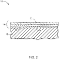
- the coating system 14 is represented in FIG. 1 as containing each of multiple layers 16, 18, 20, 22 and 24 whose compositions and functions will be discussed below, it will become apparent from the following discussion that one or more of these layers could be omitted from the coating system 14.
- the coating system 14 of FIG. 1 represents one of a variety of different coating systems within the scope of the invention.
- FIG. 2 represents a multi-layer thermal coating system 14 without layers 18 or 24.
- TBC thermal barrier coating
- Other optional layers represented in FIG. 1 include an intermediate layer 20 between the TBC 22 and bond coat 16, an erosion barrier coating 18 that is deposited as the outermost layer of the component 10, and a transitional layer 24 between the TBC 22 and erosion barrier coating 18.
- the bond coat 16 of the coating system 14 serves to adhere the other layers 18, 20, 22, and 24 to the substrate 12.
- the bond coat 16 may be an aluminum-rich composition of a type typically used with TBC systems for gas turbine engine components, such as an overlay coating of an MCrAlX alloy or a diffusion coating such as a diffusion aluminide (including diffusion aluminide coatings modified by a precious metal, for example, platinum) of a type known in the art.
- a particular example is a NiCrAlY composition of a type known in the art.
- a suitable thickness for the bond coat 16 is about 0.007 inch (about 175 micrometers), though lesser and greater thicknesses are foreseeable and within the scope of the invention as long as the bond coat 16 is capable of providing the desired functions of protecting the substrate 12 and anchoring the TBC system 14.
- Aluminum-rich bond coats of the types noted above develop an aluminum oxide (alumina) scale (not shown), which is thermally grown by oxidation of the bond coat 16.
- the TBC 22 is employed to protect the substrate 12 it covers from high operating temperatures.
- Hot gas path (HGP) components such as buckets, nozzles, and shrouds in turbine engines burning liquid fuels are often protected by thermal barrier coatings (TBCs).
- TBCs thermal barrier coatings
- the TBC 22 preferably contains a material having a relatively low thermal conductivity compared to traditional partially stabilized YSZ (e.g., 6-8%YSZ) coatings known in the art. Increased thermal insulation properties reduce instability of the coating system 14 at higher temperatures thereby allowing higher efficiency with increased reliability and therefore a longer coating system life span.
- the TBC 22 is deposited from a powder preferably by a thermal spraying process, such as air plasma spraying (APS).
- APS air plasma spraying
- a suitable thickness range for the TBC 22 is about 125 to about 1600 micrometers, depending on the particular application, though lesser and greater thicknesses are foreseeable and within the scope of the invention.
- the erosion barrier coating 18 may be provided to further protect the component 10 and the underlying layers 16, 20, 22, and 24 from solid particle erosion and foreign object damage during operation.
- the erosion barrier coating 18 can be formed of any suitable erosion-resistant material known in the art, but in preferred embodiments is formed of a constituent of the powder used to form the TBC 22, as will be discussed below.
- a suitable thickness range for the erosion barrier coating 18 is about 100 to about 400 micrometers, depending on the particular application, though lesser and greater thicknesses are foreseeable and within the scope of the invention.
- the intermediate layer 20 is optional but useful in certain applications to promote the adhesion of the TBC 22 to the bond coat 16 and the underlying substrate 12 of the component 10.
- Suitable materials for the intermediate layer 20 will depend on the particular compositions of the bond coat 16 and TBC 22, though notable materials include zirconia partially or fully stabilized with yttria (YSZ) or another oxide such as magnesia, ceria, scandia and/or calcia, and optionally other oxides to reduce thermal conductivity.
- a suitable thickness range for the intermediate layer 20 is about 50 to about 150 micrometers, depending on the particular application, though lesser and greater thicknesses are foreseeable and within the scope of the invention.
- the transitional layer 24 is another optional layer of the coating system 14 that, if present, may be used to mitigate a potential CTE mismatch between the TBC 22 and the erosion barrier coating 18, and/or inhibit reactions between the TBC 22 and erosion barrier coating 18.
- Suitable materials for the transitional layer 24 will depend on the particular compositions of the TBC 22 and erosion barrier coating 18, though notable materials include zirconia partially or fully stabilized with yttria (YSZ) or another oxide such as magnesia, ceria, scandia and/or calcia, and optionally other oxides to reduce thermal conductivity.
- YSZ zirconia partially or fully stabilized with yttria
- magnesia, ceria, scandia and/or calcia and optionally other oxides to reduce thermal conductivity.
- Suitable thicknesses for the transitional layer 24 will depend on the particular application, though thicknesses in a range of about 20 to about 130 micrometers are typically adequate. Lesser and greater thicknesses for the transitional
- particles of the powder used to form the TBC 22 are tailored so that the TBC 22 exhibits a low thermal conductivity and enhanced resistance to erosion.
- powder surface properties and grain boundary interactions may be tailored by forming the particle 30 to have an inner core 32 surrounded by and preferably entirely encased within an outer region 34 of the particle 30, wherein the inner core 32 and outer region 34 are formed of different materials.
- the inner core has a lower thermal conductivity than the outer region and the outer region is more erosion resistant relative to the inner core.
- compositional interfaces between the inner core 32 and the outer region 34 will in itself hinder thermal conduction.
- the ceramic composition of the inner core 32 is preferably initially in the form of a particle that can be made by a reverse coprecipitation process.
- Typical coprecipitation processes are carried out in an initial acidic reaction environment that subsequently changes slowly to basic, whereas reverse coprecipitation processes occur in a constant strong basic reaction environment.
- Such a reaction environment is believed to allow for improved control of the hydrolysis-complex process, resulting in a better control of morphology, size, crystalline phase and the chemical composition of the final precipitate.
- oxides with a desired molar ratio may be dissolved in nitric acid (0.1 M) and distilled water at about 90°C at a pH of about 10 to about 13.
- the resulting precipitate may be processed to form the inner core 32 of the powder particle 30.
- Processing of the precipitate may include filtering, washing with deionized water, calcination, and milling.
- a powder made up of inner cores 32 formed in this manner may be subsequently blended with an organic binder, such as ethanol and polyethyleneimine, and spray dried at elevated temperatures, such as about 100 to about 150°C, to give the powder a more uniform consistency.
- the inner cores 32 may be formed by blending sub-micron constituents in a slurry. The slurry may then be spray dried to achieve a desired particle size and sintered for increased strength.
- Yet another method includes forming the inner cores 32 in an arc fusion process followed by milling the particles to a desired size.
- the inner cores 32 are surface coated to form the outer region 34 of each powder particle 30.
- the inner cores 32 may be coated by a chemical vapor deposition (CVD) process or by blending the inner cores 32 in a slurry comprising the material for the outer region 34, spray drying, and sintering the resulting powder particles 30 for increased strength.
- a preferred average particle size (as measured along a major axis) of the resulting powder particles 30 will typically depend on the method by which they will be deposited. For example, if the powder particles 30 will be deposited by air plasma spraying (APS), a suitable average particle size is about 10 to about 90 micrometers.
- a suitable average particle size is about 1 to about 15 micrometers. It is believed that smaller particle sizes promote an increased number of splat boundaries per unit length in a coating formed therefrom relative to coatings formed of larger particle sizes, which is believed to enhance strain tolerance, increase crack propagation tortuosity and thus improve fracture toughness and erosion resistance.
- the inner core 32 is preferably tailored to have a thermal conductivity up to about 1 Wm -1 k- -1 , and more preferably between about 0.5 to about 1 Wm -1 k -1 , and is formed of the materials disclosed in claim 1. Compositions having low concentrations of ytterbia are believed to provide decreased thermal conductivity.
- Yb-Zr-based oxide compositions preferred for the inner core 32 comprise about 20 to about 70 wt.% ytterbia, and more preferably about 45 to about 70 wt.% ytterbia, the balance being zirconia and incidental impurities.
- incidental impurities refers to those elements that that may be difficult to completely eliminate from an alloy due to processing limitations, yet are not present in sufficient quantities to significantly alter or degrade the desired properties of the alloy, for example, rare earth oxide impurities having levels of less than about 2 wt.% and other impurities having levels of less than about 0.5 wt.% within the oxide composition.
- the TBC 22 may comprise zirconia doped with ytterbia and lanthanum oxide (La 2 O 3 ; lanthana), wherein the contents of ytterbia (Yb 3+ , 0.985 A°) and lanthana (La 3+ , 1.16 A°) are sufficiently high to promote the substitution of Yb3+ and La3+ ions within the material.
- Yb-La-Zr-based oxide compositions can be regarded as a solid solution of Yb 3+ taking the site of La 3+ in La 2 Zr 2 O 7 ceramics or as Yb 3+ being substituted by La 3+ in Yb 2 Zr 2 O 7 ceramics.
- Preferred Yb-La-Zr-based oxide compositions comprise about 30 to about 40 wt.% ytterbia and about 10 to about 25 wt.% lanthana, the latter of which may be partially or entirely substituted with samarium oxide (Sm 2 O 3 ; samaria).
- compositions may further include hafnia (HfO 2 ) and/or tantala (Ta 2 O 5 ), a nonlimiting example of which is about 30.5 wt.% ytterbia, about 24.8 wt.% lanthana and/or samaria, about 1.4 wt.% hafiiia, about 1.5 wt.% tantala, the balance being zirconia and incidental impurities.
- hafnia HfO 2
- Ta 2 O 5 tantala
- the Yb-La-Zr-based oxide compositions described above for the inner core 32 are characterized by a mixed pyrochlore structure showing significant drop in thermal conductivity.
- a pyrochlore structure possesses inherently poorer fracture toughness as compared to traditional partially stabilized YSZ (e.g., 6-8%YSZ). Therefore, the outer region 34 is provided to protect the inner core 32 from solid particle erosion and foreign object damage during operation.
- the outer region 34 deposited on the surface of the inner core 32 may be formed of erosion resistance materials including, but not limited to, zirconia doped with low concentrations of lanthana (below about 20 wt.% lanthana, preferably about 3 to about 10 wt.% lanthana), zirconia doped with low concentrations of ytterbia (below about 10 wt.% ytterbia, preferably about 2 to about 12 wt.% ytterbia), oxides of mischmetal (any alloy of rare earth elements in naturally occurring proportions), zirconia doped with mischmetal (below about 75 wt.% mischmetal), zirconia doped with ytterbia and mischmetal (below about 30 wt.% ytterbia and below about 25 wt.% mischmetal), zirconia doped with high levels of ytterbia (below about 55 wt.% ytterbia), zi
- a suitable thickness range for the inner core 32 and the outer region 34 depends on the particular deposition method.
- the inner core 32 preferably has a diameter or about 5 to about 6 micrometers and the outer region 34 has a thickness of about 1 to about 2 micrometers.
- the inner core 32 preferably has a diameter or about 10 to about 60 micrometers and the outer region 34 has a thickness of about 3 to about 30 micrometers.
- lesser and greater thicknesses are foreseeable and within the scope of the invention.
- An exemplary powder composition includes powder particles 30 comprising an inner core 32 formed of a composition consisting of about 45 wt.% to about 70 wt.% ytterbia and the balance being zirconia and incidental impurities, and an outer region 34 formed of a composition consisting of about 1 wt.% to about 5 wt.% ytterbia and about 2 wt.% to about 8 wt.% lanthana and the balance being zirconia and incidental impurities.
- the powder particles 30 may comprise an inner core 32 formed a composition consisting of about 45 wt.% to about 70 wt.% ytterbia and the balance being zirconia and incidental impurities, and an outer region 34 formed of a composition consisting of about 8 wt.% to about 18 wt.% ytterbia.
- the powder particles 30 may comprise an inner core 32 formed of a composition consisting of about 30 wt.% to about 40 wt.% ytterbia, about 10 wt.% to about 25 wt.% lanthana and/or samaria, and the balance being zirconia and incidental impurities, and an outer region 34 formed of a composition consisting of about 8 wt.% to about 18 wt.% ytterbia.
- the powder particles 30 may comprise an inner core 32 formed of a composition consisting of about 30 wt.% to about 40 wt.% ytterbia, about 10 wt.% to about 25 wt.% lanthana and/or samaria, and the balance being zirconia and incidental impurities, and an outer region 34 formed of a composition consisting of about 25 wt.% to about 75 wt.% mischmetal, and the balance being zirconia and incidental impurities.
- the optional erosion barrier coating 18 can be formed of one or more of the compositions described above for the outer region 34 of the powder particles 30.
- the erosion barrier coating 18 may be formed by depositing a powder whose particles are, for example, a Yb-Zr-based oxide composition with low concentrations of ytterbia, a La-Zr-based oxide composition having a low level of lanthana, a Yb-Sm-Zr-based oxide composition having a low level of ytterbia, a mischmetal-based oxide composition, or a Yb-La-Zr-based oxide composition, as described above for the outer regions 34 of the powder particles 30 that are used to form the TBC 22.
- the erosion barrier coating 18 may be formed, for example, by low temperature processes such as SPPS or a sol-gel process to include oxide whiskers (shot fibers) 36 randomly distributed in the erosion barrier coating 18 for improved erosion and oxidation resistance, as schematically represented in FIG. 5 (not to scale).
- the whiskers 36 are preferably about 1 to about 5 micrometers in diameter and about 5 to about 20 micrometers in length, though lesser and greater diameters and lengths are also within the scope of the invention.
- the whiskers 36 are randomly distributed throughout the erosion barrier coating 18 having a volume fraction of about 10 to about 40%.
- the whiskers 36 may be comprised of any suitable oxide such as, but not limited to, aluminum oxide and titanium oxide.
- a nonlimiting example of oxide whiskers 36 can be found in U.S. Patent 8,272,843 to Ryznic et al. ,
- the thermal barrier coating system 14 is believed to provide improved thermal and erosion protection for the substrate 12 that are attributable to the compositions of the inner cores 32 and outer regions 34 of the particles 30 used to form the TBC 22 and, optionally, the erosion barrier coating 18.
- Suitable methods of depositing the layers 18, 20, 22, and 24 of the above embodiments include, but are not limited to, sol-gel processes, solution plasma spray processes, suspension plasma processes, high velocity air fuel thermal spray processes, high velocity oxy-fuel thermal spray processes, and plasma spraying (air (APS), vacuum (VPS), solution precursor plasma spraying (SPPS), and low pressure (LPPS)).
- thermal barrier coating includes coatings referred to as dense vertically cracked (DVC) TBCs, which are deposited by plasma spraying to have vertical microcracks to improve durability.
- DVC dense vertically cracked
- the thermal barrier coating system 14 preferably undergoes heat treatment to relieve residual stresses.
- An exemplary heat treatment is in a temperature range of about 2000 to about 2100°F (about 1090 to about 1150°C) in a vacuum for a duration of about two to about four hours.
- a particularly preferred heat treatment is believed to be about 2050°F (about 1120°C) in a vacuum for about two hours.
- This disclosed heat treatment is merely exemplary and other effective heat treatments may be employed.
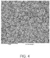
- Yb-La-Hf-Ta-Zr-based oxide compositions of the type described above and deposited by plasma spraying, such as APS to form DVC TBCs, as well as SPPS were observed to form a well-connected microstructure with isolated pores that were circular in shape.
- Other dopants, such as hafnia and tantala were identified at the grain boundaries.
- the microstructures of the layers comprised Yb-Zr oxide grains surrounded by La-Zr oxide grain boundaries. It is believed that the Yb-Zr oxide grains provide low thermal conductivity properties while the La-Zr oxide grains promote erosion resistance.
- An exemplary microstructure is shown in FIG. 4 . Therein, the darker grains correspond to grains with a relatively higher content of ytterbia and the lighter grains correspond to grains with a relatively higher content of lanthana.
Description
- The present invention generally relates to ceramic powders for forming coatings on components exposed to high temperatures, such as the hostile thermal environments of gas turbines. More particularly, this invention is directed to a ceramic powder having improved thermal insulation and erosion resistance properties for applications such as thermal barrier coatings (TBCs).
- Improvements are continuously sought to increase the operating temperatures of gas turbines to achieve higher energy output and efficiencies. As a consequence of the higher operating temperatures, hot gas path (HGP) components within turbines are required to withstand the ever increasing temperatures. Often, hot gas path components are expected to operate at temperatures near their melting point. Consequently, complex cooling processes and improved materials are used to mitigate damage to the hot gas path components. In many instances, circumstances may necessitate further increasing the operating temperature of hot gas path components by depositing a thermal barrier coating on their exterior surfaces that are directly exposed to the hot gas path. The use of thermal barrier coatings (TBCs) on components such as combustors, high pressure turbine (HPT) blades, vanes and shrouds is increasing in commercial as well as military gas turbine engines. The thermal insulation provided by a TBC enables such components to survive higher operating temperatures, increases component durability, and improves engine reliability. TBCs are typically formed of a ceramic material and deposited on an environmentally-protective bond coat to form what is termed a TBC system.
- Notable examples of ceramic materials for TBCs include zirconia partially or fully stabilized with yttria (yttrium oxide; Y2O3) or another oxide, such as magnesia, ceria, scandia and/or calcia, and optionally other oxides to reduce thermal conductivity. Binary yttria-stabilized zirconia (YSZ) is widely used as a TBC material because of its high temperature capability, low thermal conductivity, and relative ease of deposition. Zirconia is stabilized to inhibit a tetragonal to monoclinic crystal phase transformation at about 1000°C, which results in a volume change that can cause spallation. At room temperature, the more stable tetragonal phase is obtained and the monoclinic phase is minimized if zirconia is stabilized by at least about six weight percent yttria. A stabilizer (e.g., yttria) content of seventeen weight percent or more ensures a fully stable cubic crystal phase. The conventional practice has been to partially stabilize zirconia with six to eight weight percent yttria (6-8%YSZ) to obtain a TBC that is adherent and spallation-resistant when subjected to high temperature thermal cycling. Furthermore, partially stabilized YSZ (e.g., 6-8%YSZ) is known to be more erosion resistant than fully stabilized YSZ (e.g., 20%YSZ).
- Various processes can be used to deposit TBC materials, including thermal spray processes such as air plasma spraying (APS), vacuum plasma spraying (VPS), low pressure plasma spraying (LPPS), and high velocity oxy-fuel (HVOF). TBCs employed in the highest temperature regions of gas turbine engines are often deposited by a physical vapor deposition (PVD), and particularly electron beam physical vapor deposition (EBPVD), which yields a columnar, strain-tolerant grain structure that is able to expand and contract without causing damaging stresses that lead to spallation. Similar columnar microstructures can be produced using other atomic and molecular vapor processes, such as sputtering (e.g., high and low pressure, standard or collimated plume), ion plasma/cathodic arc deposition, and all forms of melting and evaporation deposition processes (e.g., laser melting, etc.). TBCs formed by the various methods noted above generally have a lower thermal conductivity than a dense ceramic of the same composition as a result of the presence of microstructural defects and pores at and between grain boundaries of the TBC microstructure.
-
US 2004/0106015 A1 discloses a particulate which is an agglomerate comprising granules and an additive finely dispersed on the surfaces of the granules. An outer layer is mechanically toughened by partial sintering.US 2012/177836 A1 discloses zirconia powders for use in thermal barrier coatings and high-temperature abradable coatings. - In order to improve TBC coatings, composite or clad powders have been developed which comprise more than one material wherein each material offers its own inherent material benefits. For example, the powder may be a metal-ceramic composite comprising a ductile metal matrix and a hard, wear resistant carbide phase. Alternatively, the powder may be a ceramic-polymer composite comprising either ceramic grains encapsulated in a polymer or a polymer encapsulated in a ceramic. The polymer material may be removed through oxidization of the resulting coating after consolidation. Removal of the polymer material yields an open porosity within the coating allowing the ceramic to be compliant in a turbine blade rub event. However, composite powders formed of more than one ceramic material are difficult to reliably form due to processing limitations.
- In view of the above, it can be appreciated that improved coating materials are continuously sought in order to allow components to be capable of operating in higher temperature environments.
- The present invention provides ceramic powders and methods of forming ceramic powders that are capable of being used to form coatings to enable components to survive in high temperatures environments, such as the hostile thermal environment of a gas turbine.
- According to a first aspect of the invention, a ceramic powder according to
claim 1 is provided. - According to a second aspect of the invention, a method according to claim 7 is provided.
- A technical effect of the invention is the ability to form tailored ceramic powders that are capable of being deposited to form a coating on a component and enable the component to withstand higher temperatures. In particular, it is believed that thermal barrier coatings (TBC) formed from the ceramic powders are capable of exhibiting both low thermal conductivity and improved erosion resistance.
- Other aspects and advantages of this invention will be better appreciated from the following detailed description.
-
-
FIG. 1 schematically represents a cross-section through a coating system in accordance with an aspect of this invention. -
FIG. 2 schematically represents a cross-section through a coating system in accordance with another aspect of this invention. -
FIG. 3 schematically represents a cross-section through a powder particle that can be produced and used to form coatings in accordance with various aspects of this invention. -
FIG. 4 is a scanned images of a coating system produced by a process within the scope of this invention. -
FIG. 5 schematically represents a cross-section through a coating system in accordance with another aspect of this invention. - The present invention is generally applicable to components subjected to high temperatures, and particularly to components such as high and low pressure turbine vanes (nozzles) and blades (buckets), shrouds, combustor liners and augmentor hardware of gas turbine engines. The invention provides ceramic powders, methods of forming ceramic powders, and coating systems that can be formed with the ceramic powders and are suitable for protecting the surfaces of gas turbine engine components that are subjected to hot combustion gases. While advantages of this invention will be described with reference to gas turbine engine components, the teachings of the invention are generally applicable to any component on which a coating system may be used to protect the component from a high temperature environment.
- In accordance with a first embodiment of the invention, a multi-layer thermal
barrier coating system 14 is schematically represented inFIG. 1 . As shown, a substrate (surface region) 12 of acomponent 10 is protected by thecoating system 14. Thecoating system 14 reduces the operating temperature of thecomponent 10, thereby enabling thecomponent 10 to survive within higher temperature environments than otherwise possible. While thecoating system 14 is represented inFIG. 1 as containing each ofmultiple layers coating system 14. As such, thecoating system 14 ofFIG. 1 represents one of a variety of different coating systems within the scope of the invention. For example,FIG. 2 represents a multi-layerthermal coating system 14 withoutlayers - An
interior layer 22 of thecoating system 14 represented inFIG. 1 will be referred to as a thermal barrier coating (TBC) 22 that is adhered to thesubstrate 12 by abond coat 16 directly applied to thesubstrate 12. Other optional layers represented inFIG. 1 include anintermediate layer 20 between theTBC 22 andbond coat 16, anerosion barrier coating 18 that is deposited as the outermost layer of thecomponent 10, and atransitional layer 24 between theTBC 22 anderosion barrier coating 18. - As noted above, the
bond coat 16 of thecoating system 14 serves to adhere theother layers substrate 12. Thebond coat 16 may be an aluminum-rich composition of a type typically used with TBC systems for gas turbine engine components, such as an overlay coating of an MCrAlX alloy or a diffusion coating such as a diffusion aluminide (including diffusion aluminide coatings modified by a precious metal, for example, platinum) of a type known in the art. A particular example is a NiCrAlY composition of a type known in the art. A suitable thickness for thebond coat 16 is about 0.007 inch (about 175 micrometers), though lesser and greater thicknesses are foreseeable and within the scope of the invention as long as thebond coat 16 is capable of providing the desired functions of protecting thesubstrate 12 and anchoring theTBC system 14. Aluminum-rich bond coats of the types noted above develop an aluminum oxide (alumina) scale (not shown), which is thermally grown by oxidation of thebond coat 16. - The
TBC 22 is employed to protect thesubstrate 12 it covers from high operating temperatures. Hot gas path (HGP) components such as buckets, nozzles, and shrouds in turbine engines burning liquid fuels are often protected by thermal barrier coatings (TBCs). According to a preferred aspect of the invention discussed in more detail below, theTBC 22 preferably contains a material having a relatively low thermal conductivity compared to traditional partially stabilized YSZ (e.g., 6-8%YSZ) coatings known in the art. Increased thermal insulation properties reduce instability of thecoating system 14 at higher temperatures thereby allowing higher efficiency with increased reliability and therefore a longer coating system life span. According to another preferred aspect of the invention, theTBC 22 is deposited from a powder preferably by a thermal spraying process, such as air plasma spraying (APS). A suitable thickness range for theTBC 22 is about 125 to about 1600 micrometers, depending on the particular application, though lesser and greater thicknesses are foreseeable and within the scope of the invention. - The
erosion barrier coating 18 may be provided to further protect thecomponent 10 and theunderlying layers erosion barrier coating 18 can be formed of any suitable erosion-resistant material known in the art, but in preferred embodiments is formed of a constituent of the powder used to form theTBC 22, as will be discussed below. A suitable thickness range for theerosion barrier coating 18 is about 100 to about 400 micrometers, depending on the particular application, though lesser and greater thicknesses are foreseeable and within the scope of the invention. - The
intermediate layer 20 is optional but useful in certain applications to promote the adhesion of theTBC 22 to thebond coat 16 and theunderlying substrate 12 of thecomponent 10. Suitable materials for theintermediate layer 20 will depend on the particular compositions of thebond coat 16 andTBC 22, though notable materials include zirconia partially or fully stabilized with yttria (YSZ) or another oxide such as magnesia, ceria, scandia and/or calcia, and optionally other oxides to reduce thermal conductivity. A suitable thickness range for theintermediate layer 20 is about 50 to about 150 micrometers, depending on the particular application, though lesser and greater thicknesses are foreseeable and within the scope of the invention. - The
transitional layer 24 is another optional layer of thecoating system 14 that, if present, may be used to mitigate a potential CTE mismatch between theTBC 22 and theerosion barrier coating 18, and/or inhibit reactions between theTBC 22 anderosion barrier coating 18. Suitable materials for thetransitional layer 24 will depend on the particular compositions of theTBC 22 anderosion barrier coating 18, though notable materials include zirconia partially or fully stabilized with yttria (YSZ) or another oxide such as magnesia, ceria, scandia and/or calcia, and optionally other oxides to reduce thermal conductivity. Suitable thicknesses for thetransitional layer 24 will depend on the particular application, though thicknesses in a range of about 20 to about 130 micrometers are typically adequate. Lesser and greater thicknesses for thetransitional layer 24 are foreseeable and within the scope of the invention. - According to another aspect of the present invention, particles of the powder used to form the
TBC 22 are tailored so that theTBC 22 exhibits a low thermal conductivity and enhanced resistance to erosion. As represented by apowder particle 30 shown inFIG. 3 , powder surface properties and grain boundary interactions may be tailored by forming theparticle 30 to have aninner core 32 surrounded by and preferably entirely encased within anouter region 34 of theparticle 30, wherein theinner core 32 andouter region 34 are formed of different materials. The inner core has a lower thermal conductivity than the outer region and the outer region is more erosion resistant relative to the inner core. - In addition, it is believed that the compositional interfaces between the
inner core 32 and theouter region 34 will in itself hinder thermal conduction. - The ceramic composition of the
inner core 32 is preferably initially in the form of a particle that can be made by a reverse coprecipitation process. Typical coprecipitation processes are carried out in an initial acidic reaction environment that subsequently changes slowly to basic, whereas reverse coprecipitation processes occur in a constant strong basic reaction environment. Such a reaction environment is believed to allow for improved control of the hydrolysis-complex process, resulting in a better control of morphology, size, crystalline phase and the chemical composition of the final precipitate. For example, oxides with a desired molar ratio may be dissolved in nitric acid (0.1 M) and distilled water at about 90°C at a pH of about 10 to about 13. Once the reaction is complete, the resulting precipitate may be processed to form theinner core 32 of thepowder particle 30. Processing of the precipitate may include filtering, washing with deionized water, calcination, and milling. A powder made up ofinner cores 32 formed in this manner may be subsequently blended with an organic binder, such as ethanol and polyethyleneimine, and spray dried at elevated temperatures, such as about 100 to about 150°C, to give the powder a more uniform consistency. Alternatively, theinner cores 32 may be formed by blending sub-micron constituents in a slurry. The slurry may then be spray dried to achieve a desired particle size and sintered for increased strength. Yet another method includes forming theinner cores 32 in an arc fusion process followed by milling the particles to a desired size. - Thereafter, the
inner cores 32 are surface coated to form theouter region 34 of eachpowder particle 30. Theinner cores 32 may be coated by a chemical vapor deposition (CVD) process or by blending theinner cores 32 in a slurry comprising the material for theouter region 34, spray drying, and sintering the resultingpowder particles 30 for increased strength. A preferred average particle size (as measured along a major axis) of the resultingpowder particles 30 will typically depend on the method by which they will be deposited. For example, if thepowder particles 30 will be deposited by air plasma spraying (APS), a suitable average particle size is about 10 to about 90 micrometers. If thepowder particles 30 will be deposited by solution precursor plasma spraying (SPPS), a suitable average particle size is about 1 to about 15 micrometers. It is believed that smaller particle sizes promote an increased number of splat boundaries per unit length in a coating formed therefrom relative to coatings formed of larger particle sizes, which is believed to enhance strain tolerance, increase crack propagation tortuosity and thus improve fracture toughness and erosion resistance. - The
inner core 32 is preferably tailored to have a thermal conductivity up to about 1 Wm-1k--1, and more preferably between about 0.5 to about 1 Wm-1k-1, and is formed of the materials disclosed inclaim 1. Compositions having low concentrations of ytterbia are believed to provide decreased thermal conductivity. Yb-Zr-based oxide compositions preferred for theinner core 32 comprise about 20 to about 70 wt.% ytterbia, and more preferably about 45 to about 70 wt.% ytterbia, the balance being zirconia and incidental impurities. As used herein, the term incidental impurities refers to those elements that that may be difficult to completely eliminate from an alloy due to processing limitations, yet are not present in sufficient quantities to significantly alter or degrade the desired properties of the alloy, for example, rare earth oxide impurities having levels of less than about 2 wt.% and other impurities having levels of less than about 0.5 wt.% within the oxide composition. - In the case of zirconia doped with at least two dopants having significantly different atomic sizes and weights, it is believed that by substituting a large ion with another much heavier and smaller ion, the substituted large ion will remain in a relaxed state. The phonon scattering effect is believed to then be due to both localized vibration of the smaller ion and intrinsic oxygen vacancies resulting in an abnormal heat capacity. As an example, the
TBC 22 may comprise zirconia doped with ytterbia and lanthanum oxide (La2O3; lanthana), wherein the contents of ytterbia (Yb3+, 0.985 A°) and lanthana (La3+, 1.16 A°) are sufficiently high to promote the substitution of Yb3+ and La3+ ions within the material. These Yb-La-Zr-based oxide compositions can be regarded as a solid solution of Yb3+ taking the site of La3+ in La2Zr2O7 ceramics or as Yb3+ being substituted by La3+ in Yb2Zr2O7 ceramics. Preferred Yb-La-Zr-based oxide compositions comprise about 30 to about 40 wt.% ytterbia and about 10 to about 25 wt.% lanthana, the latter of which may be partially or entirely substituted with samarium oxide (Sm2O3; samaria). Exemplary compositions may further include hafnia (HfO2) and/or tantala (Ta2O5), a nonlimiting example of which is about 30.5 wt.% ytterbia, about 24.8 wt.% lanthana and/or samaria, about 1.4 wt.% hafiiia, about 1.5 wt.% tantala, the balance being zirconia and incidental impurities. - The Yb-La-Zr-based oxide compositions described above for the
inner core 32 are characterized by a mixed pyrochlore structure showing significant drop in thermal conductivity. However, such a pyrochlore structure possesses inherently poorer fracture toughness as compared to traditional partially stabilized YSZ (e.g., 6-8%YSZ). Therefore, theouter region 34 is provided to protect theinner core 32 from solid particle erosion and foreign object damage during operation. Theouter region 34 deposited on the surface of theinner core 32 may be formed of erosion resistance materials including, but not limited to, zirconia doped with low concentrations of lanthana (below about 20 wt.% lanthana, preferably about 3 to about 10 wt.% lanthana), zirconia doped with low concentrations of ytterbia (below about 10 wt.% ytterbia, preferably about 2 to about 12 wt.% ytterbia), oxides of mischmetal (any alloy of rare earth elements in naturally occurring proportions), zirconia doped with mischmetal (below about 75 wt.% mischmetal), zirconia doped with ytterbia and mischmetal (below about 30 wt.% ytterbia and below about 25 wt.% mischmetal), zirconia doped with high levels of ytterbia (below about 55 wt.% ytterbia), zirconia doped with ytterbia and lanthana (below about 55 wt.% ytterbia and below about 8 wt.% lanthana and/or samaria), and the like. A suitable thickness range for theinner core 32 and theouter region 34 depends on the particular deposition method. For example, for SPPS, theinner core 32 preferably has a diameter or about 5 to about 6 micrometers and theouter region 34 has a thickness of about 1 to about 2 micrometers. For APS, theinner core 32 preferably has a diameter or about 10 to about 60 micrometers and theouter region 34 has a thickness of about 3 to about 30 micrometers. However, lesser and greater thicknesses are foreseeable and within the scope of the invention. - An exemplary powder composition includes
powder particles 30 comprising aninner core 32 formed of a composition consisting of about 45 wt.% to about 70 wt.% ytterbia and the balance being zirconia and incidental impurities, and anouter region 34 formed of a composition consisting of about 1 wt.% to about 5 wt.% ytterbia and about 2 wt.% to about 8 wt.% lanthana and the balance being zirconia and incidental impurities. In another example, thepowder particles 30 may comprise aninner core 32 formed a composition consisting of about 45 wt.% to about 70 wt.% ytterbia and the balance being zirconia and incidental impurities, and anouter region 34 formed of a composition consisting of about 8 wt.% to about 18 wt.% ytterbia. In another example, thepowder particles 30 may comprise aninner core 32 formed of a composition consisting of about 30 wt.% to about 40 wt.% ytterbia, about 10 wt.% to about 25 wt.% lanthana and/or samaria, and the balance being zirconia and incidental impurities, and anouter region 34 formed of a composition consisting of about 8 wt.% to about 18 wt.% ytterbia. In yet another example, thepowder particles 30 may comprise aninner core 32 formed of a composition consisting of about 30 wt.% to about 40 wt.% ytterbia, about 10 wt.% to about 25 wt.% lanthana and/or samaria, and the balance being zirconia and incidental impurities, and anouter region 34 formed of a composition consisting of about 25 wt.% to about 75 wt.% mischmetal, and the balance being zirconia and incidental impurities. - As previously noted, the optional
erosion barrier coating 18 can be formed of one or more of the compositions described above for theouter region 34 of thepowder particles 30. As such, theerosion barrier coating 18 may be formed by depositing a powder whose particles are, for example, a Yb-Zr-based oxide composition with low concentrations of ytterbia, a La-Zr-based oxide composition having a low level of lanthana, a Yb-Sm-Zr-based oxide composition having a low level of ytterbia, a mischmetal-based oxide composition, or a Yb-La-Zr-based oxide composition, as described above for theouter regions 34 of thepowder particles 30 that are used to form theTBC 22. According to an aspect of the invention, theerosion barrier coating 18 may be formed, for example, by low temperature processes such as SPPS or a sol-gel process to include oxide whiskers (shot fibers) 36 randomly distributed in theerosion barrier coating 18 for improved erosion and oxidation resistance, as schematically represented inFIG. 5 (not to scale). Thewhiskers 36 are preferably about 1 to about 5 micrometers in diameter and about 5 to about 20 micrometers in length, though lesser and greater diameters and lengths are also within the scope of the invention. Thewhiskers 36 are randomly distributed throughout theerosion barrier coating 18 having a volume fraction of about 10 to about 40%. Thewhiskers 36 may be comprised of any suitable oxide such as, but not limited to, aluminum oxide and titanium oxide. A nonlimiting example ofoxide whiskers 36 can be found inU.S. Patent 8,272,843 to Ryznic et al. , - Once deposited onto a
substrate 12 of thecomponent 10, the thermalbarrier coating system 14 is believed to provide improved thermal and erosion protection for thesubstrate 12 that are attributable to the compositions of theinner cores 32 andouter regions 34 of theparticles 30 used to form theTBC 22 and, optionally, theerosion barrier coating 18. Suitable methods of depositing thelayers TBC 22 by a thermal spraying process, such as air plasma spraying (APS), by which softened particles deposit as "splats" on the deposition surface formed by thebond coat 16, and result in theTBC 22 having noncolumnar, irregular flattened grains and a degree of inhomogeneity and porosity. This category of thermal barrier coating includes coatings referred to as dense vertically cracked (DVC) TBCs, which are deposited by plasma spraying to have vertical microcracks to improve durability. Such processes and their parameters are disclosed in U.S. Patent No.U.S. Patent Nos. 5830586 ,5897921 ,5989343 and6047539 . Alternatively, theTBC 22 may be formed to have columnar grains with defined spacing for structural integrity of theTBC 22. - Following the deposition of its layers on the
substrate 12, the thermalbarrier coating system 14 preferably undergoes heat treatment to relieve residual stresses. An exemplary heat treatment is in a temperature range of about 2000 to about 2100°F (about 1090 to about 1150°C) in a vacuum for a duration of about two to about four hours. A particularly preferred heat treatment is believed to be about 2050°F (about 1120°C) in a vacuum for about two hours. This disclosed heat treatment is merely exemplary and other effective heat treatments may be employed. - In investigations leading to this invention, layers of Yb-La-Hf-Ta-Zr-based oxide compositions of the type described above and deposited by plasma spraying, such as APS to form DVC TBCs, as well as SPPS were observed to form a well-connected microstructure with isolated pores that were circular in shape. Other dopants, such as hafnia and tantala, were identified at the grain boundaries. Furthermore, the microstructures of the layers comprised Yb-Zr oxide grains surrounded by La-Zr oxide grain boundaries. It is believed that the Yb-Zr oxide grains provide low thermal conductivity properties while the La-Zr oxide grains promote erosion resistance. An exemplary microstructure is shown in
FIG. 4 . Therein, the darker grains correspond to grains with a relatively higher content of ytterbia and the lighter grains correspond to grains with a relatively higher content of lanthana. - Therefore, the scope of the invention is defined by the following claims.
Claims (13)
- A ceramic powder containing powder particles, each of a plurality of the powder particles comprising an inner core formed of a first material and an outer region formed of a second material coated on the surface of the inner core, wherein the inner core has a lower thermal conductivity than the outer region and the outer region is more erosion resistant relative to the inner core; wherein the first material of the inner core comprises a composition chosen from the group consisting of Yb-La-Zr-based oxide compositions, Yb-Sm-Zr-based oxide compositions, and Yb-Zr-based oxide compositions and wherein the second material of the outer region comprises a composition chosen from the group consisting of Yb-Zr-based oxide compositions, La-Zr-based oxide compositions, Yb-La-Zr-based oxide compositions, Yb-Sm-Zr-based oxide compositions, Yb-mischmetal-Zr-based oxide compositions, and mischmetal-Zr-based oxide compositions, wherein mischmetal is any alloy of rare earth elements in naturally occurring proportions.
- The ceramic powder of claim 1, wherein the inner core has a thermal conductivity of 0.5 to 1.0 Wm-1k-1.
- The ceramic powder of claim 1 or claim 2, wherein the first material of the inner core consists of 30 to 40 wt.% ytterbia, 10 to 25 wt.% lanthana and/or samaria, the remainder being zirconia and incidental impurities, and the second material of the outer region consists of:
8 to 18 wt.% ytterbia, with the remainder being zirconia and incidental impurities; or 25 to 75 wt.% mischmetal, with the remainder being zirconia and incidental impurities. - The ceramic powder of any one of claims 1 to 3, wherein the first material of the inner core consists of 40 to 70 wt.% ytterbia, the remainder being zirconia and incidental impurities, and the second material of the outer region consists of:1 to 5 wt.% ytterbia, 2 to 8 wt.% lanthana, with the remainder being zirconia and incidental impurities; or8 to 18 wt.% ytterbia, with the remainder being zirconia and incidental impurities.
- A coating system formed from the ceramic powder of any preceding claim and disposed on a surface region of a component.
- A component having the coating system of claim 5 thereon.
- A method of forming a ceramic powder containing powder particles of any preceding claim, the method comprising:forming cores of the powder particles, wherein the cores are formed of a first material; and thensurface coating the cores to form an outer region of the powder particles, wherein each the outer regions is formed of a second material, each of the cores has a lower thermal conductivity than the outer region thereof, and each of the outer regions is more erosion resistant relative to the core thereof;wherein the first material of the inner core comprises a composition chosen from the group consisting of Yb-La-Zr-based oxide compositions, Yb-Sm-Zr-based oxide compositions, and Yb-Zr-based oxide compositions and wherein the second material of the outer region comprises a composition chosen from the group consisting of Yb-Zr-based oxide compositions, La-Zr-based oxide compositions, Yb-La-Zr-based oxide compositions, Yb-Sm-Zr-based oxide compositions, Yb-mischmetal-Zr-based oxide compositions, and mischmetal-Zr-based oxide compositions, wherein mischmetal is any alloy of rare earth elements in naturally occurring proportions.
- The method of claim 7, wherein the forming step includes forming precipitates by reverse coprecipitation and then processing the precipitates to form the cores.
- The method of claim 7 or claim 8, further comprising blending the cores with an organic binder and spray drying the cores after the processing step but prior to the surface coating step.
- The method of any one of claims 7 to 9, wherein the surface coating step is performed by a chemical vapor deposition process.
- The method of any one of claims 7 to 10, wherein the cores are surface coated to have an average particle size of 1 to 90 micrometers.
- The method of any one of claims 7 to 11, wherein the cores consist entirely of the first material.
- The method of any one of claims 7 to 12, wherein the outer regions consist entirely of the second material.
Applications Claiming Priority (1)
| Application Number | Priority Date | Filing Date | Title |
|---|---|---|---|
| US13/769,538 US9139477B2 (en) | 2013-02-18 | 2013-02-18 | Ceramic powders and methods therefor |
Publications (2)
| Publication Number | Publication Date |
|---|---|
| EP2767525A1 EP2767525A1 (en) | 2014-08-20 |
| EP2767525B1 true EP2767525B1 (en) | 2020-08-26 |
Family
ID=50101694
Family Applications (1)
| Application Number | Title | Priority Date | Filing Date |
|---|---|---|---|
| EP14153742.3A Active EP2767525B1 (en) | 2013-02-18 | 2014-02-04 | Ceramic powders and methods therefor |
Country Status (4)
| Country | Link |
|---|---|
| US (1) | US9139477B2 (en) |
| EP (1) | EP2767525B1 (en) |
| JP (1) | JP6386740B2 (en) |
| CN (1) | CN103992117B (en) |
Families Citing this family (7)
| Publication number | Priority date | Publication date | Assignee | Title |
|---|---|---|---|---|
| US20160010471A1 (en) * | 2013-03-11 | 2016-01-14 | General Electric Company | Coating systems and methods therefor |
| JP2018040017A (en) * | 2015-05-13 | 2018-03-15 | エリコンメテコジャパン株式会社 | Thermal spray powder, thermal spraying method and thermal spray coating |
| CA3002295A1 (en) * | 2017-06-21 | 2018-12-21 | Rolls-Royce Corporation | Impurity barrier layer for ceramic matrix composite substrate |
| CN110304919A (en) * | 2019-08-16 | 2019-10-08 | 湘潭大学 | A kind of preparation method of ceramic material and the preparation method of thermal barrier coating |
| US20220290285A1 (en) * | 2021-03-09 | 2022-09-15 | General Electric Company | High entropy ceramic thermal barrier coating |
| CN115341181B (en) * | 2022-07-29 | 2024-04-09 | 中国航发北京航空材料研究院 | Lanthanum samarium zirconium oxygen thermal barrier coating material and preparation method thereof |
| CN116082039B (en) * | 2022-12-22 | 2023-10-20 | 哈尔滨工业大学 | Preparation method of non-equivalent ion doped high-emissivity low-thermal-conductivity functional composite ceramic or coating |
Citations (1)
| Publication number | Priority date | Publication date | Assignee | Title |
|---|---|---|---|---|
| US20120177836A1 (en) * | 2005-10-07 | 2012-07-12 | Sulzer Meto (US), Inc. | High-purity fused and crushed zirconia alloy powder and method of producing same |
Family Cites Families (23)
| Publication number | Priority date | Publication date | Assignee | Title |
|---|---|---|---|---|
| JPS6141757A (en) * | 1984-08-01 | 1986-02-28 | Hitachi Ltd | Zro2-base powder for heat insulating coating |
| DE69524353T2 (en) | 1994-10-04 | 2002-08-08 | Gen Electric | High-temperature protective layer |
| US5897921A (en) | 1997-01-24 | 1999-04-27 | General Electric Company | Directionally solidified thermal barrier coating |
| US6047539A (en) | 1998-04-30 | 2000-04-11 | General Electric Company | Method of protecting gas turbine combustor components against water erosion and hot corrosion |
| US6306515B1 (en) | 1998-08-12 | 2001-10-23 | Siemens Westinghouse Power Corporation | Thermal barrier and overlay coating systems comprising composite metal/metal oxide bond coating layers |
| US6869550B2 (en) | 2000-12-08 | 2005-03-22 | Sulzer Metco (Us) Inc. | Method of producing a pre-alloyed stabilized zirconia powder |
| US6893994B2 (en) | 2002-08-13 | 2005-05-17 | Saint-Gobain Ceramics & Plastics, Inc. | Plasma spheroidized ceramic powder |
| ES2302907T3 (en) | 2002-11-22 | 2008-08-01 | Sulzer Metco (Us) Inc. | PROJECTION POWDER FOR PRODUCTION BY THERMAL PROJECTION OF A THERMAL INSULATING LAYER RESISTANT TO HIGH TEMPERATURES. |
| JP2005154885A (en) | 2003-03-26 | 2005-06-16 | Mitsubishi Heavy Ind Ltd | Material for thermal barrier coating |
| US6756119B1 (en) | 2003-04-07 | 2004-06-29 | Ensci Inc | Thin film metal oxyanion coated substrates |
| US7255940B2 (en) | 2004-07-26 | 2007-08-14 | General Electric Company | Thermal barrier coatings with high fracture toughness underlayer for improved impact resistance |
| US7166373B2 (en) | 2004-08-19 | 2007-01-23 | General Electric Company | Ceramic compositions for thermal barrier coatings with improved mechanical properties |
| JP2006104577A (en) | 2004-10-04 | 2006-04-20 | United Technol Corp <Utc> | Segmented gadolinia zirconia coating film, method for forming the same, segmented ceramic coating system and coated film component |
| JP4511987B2 (en) | 2005-04-20 | 2010-07-28 | 三菱重工業株式会社 | Thermal barrier coating material |
| US8272843B1 (en) | 2005-09-12 | 2012-09-25 | Florida Turbine Technologies, Inc. | TBC with fibrous reinforcement |
| US7622195B2 (en) | 2006-01-10 | 2009-11-24 | United Technologies Corporation | Thermal barrier coating compositions, processes for applying same and articles coated with same |
| WO2007112783A1 (en) | 2006-04-06 | 2007-10-11 | Siemens Aktiengesellschaft | Layered thermal barrier coating with a high porosity, and a component |
| WO2008060699A2 (en) | 2006-05-25 | 2008-05-22 | High Performance Coatings Inc | High temperature ceramic coatings incorporating nanoparticles |
| EP1938907A1 (en) * | 2006-12-28 | 2008-07-02 | Nederlandse Organisatie voor toegepast- natuurwetenschappelijk onderzoek TNO | Deposition of particles on a substrate |
| EP2128299B1 (en) | 2008-05-29 | 2016-12-28 | General Electric Technology GmbH | Multilayer thermal barrier coating |
| EP2305607A4 (en) * | 2008-07-07 | 2011-09-07 | Asahi Glass Co Ltd | Core-shell particle and method for producing core-shell particle |
| US8242037B2 (en) * | 2008-07-24 | 2012-08-14 | The Regents Of The University Of Michigan | Method of pressureless sintering production of densified ceramic composites |
| CH701373A1 (en) | 2009-06-30 | 2010-12-31 | Alstom Technology Ltd | Schlickerformulierung for the manufacture of thermal barrier coatings. |
-
2013
- 2013-02-18 US US13/769,538 patent/US9139477B2/en active Active
-
2014
- 2014-02-04 EP EP14153742.3A patent/EP2767525B1/en active Active
- 2014-02-14 JP JP2014026013A patent/JP6386740B2/en active Active
- 2014-02-18 CN CN201410054143.0A patent/CN103992117B/en active Active
Patent Citations (1)
| Publication number | Priority date | Publication date | Assignee | Title |
|---|---|---|---|---|
| US20120177836A1 (en) * | 2005-10-07 | 2012-07-12 | Sulzer Meto (US), Inc. | High-purity fused and crushed zirconia alloy powder and method of producing same |
Also Published As
| Publication number | Publication date |
|---|---|
| CN103992117B (en) | 2017-08-04 |
| CN103992117A (en) | 2014-08-20 |
| EP2767525A1 (en) | 2014-08-20 |
| JP2014166949A (en) | 2014-09-11 |
| US9139477B2 (en) | 2015-09-22 |
| JP6386740B2 (en) | 2018-09-05 |
| US20140235426A1 (en) | 2014-08-21 |
Similar Documents
| Publication | Publication Date | Title |
|---|---|---|
| EP2767525B1 (en) | Ceramic powders and methods therefor | |
| Kumar et al. | Processing and design methodologies for advanced and novel thermal barrier coatings for engineering applications | |
| US6586115B2 (en) | Yttria-stabilized zirconia with reduced thermal conductivity | |
| EP2766504B1 (en) | Thermal barrier coating systems and processes therefor | |
| CA2806172C (en) | Thermal barrier coatings including cmas-resistant thermal barrier coating layers | |
| EP1375701B1 (en) | Thermal barrier coating material | |
| EP1400611A1 (en) | Thermal barrier coating material comprising rare earth oxides | |
| EP1153157B1 (en) | Thermal barrier coating resistant to sintering | |
| US20150233256A1 (en) | Novel architectures for ultra low thermal conductivity thermal barrier coatings with improved erosion and impact properties | |
| US20060019119A1 (en) | Thermal barrier coatings with high fracture toughness underlayer for improved impact resistance | |
| US20110171488A1 (en) | Thermal barrier coating systems | |
| EP2778250A2 (en) | Coating systems and methods therefor | |
| JP2002522646A (en) | Multi-layer thermal insulation coating system | |
| US7537806B2 (en) | Method for producing a thermal barrier coating on a substrate | |
| US6686060B2 (en) | Thermal barrier coating material | |
| US7507482B2 (en) | Ceramic coating material | |
| EP1400607B1 (en) | Thermal barrier coating with improved strength and fracture toughness | |
| Vassen et al. | Conventional and new materials for thermal barrier coatings | |
| Ahmed et al. | A Review on Thermal Barrier Coatings | |
| WO2014184906A1 (en) | Heat shield coating member |
Legal Events
| Date | Code | Title | Description |
|---|---|---|---|
| PUAI | Public reference made under article 153(3) epc to a published international application that has entered the european phase |
Free format text: ORIGINAL CODE: 0009012 |
|
| 17P | Request for examination filed |
Effective date: 20140204 |
|
| AK | Designated contracting states |
Kind code of ref document: A1 Designated state(s): AL AT BE BG CH CY CZ DE DK EE ES FI FR GB GR HR HU IE IS IT LI LT LU LV MC MK MT NL NO PL PT RO RS SE SI SK SM TR |
|
| AX | Request for extension of the european patent |
Extension state: BA ME |
|
| R17P | Request for examination filed (corrected) |
Effective date: 20150220 |
|
| RBV | Designated contracting states (corrected) |
Designated state(s): AL AT BE BG CH CY CZ DE DK EE ES FI FR GB GR HR HU IE IS IT LI LT LU LV MC MK MT NL NO PL PT RO RS SE SI SK SM TR |
|
| STAA | Information on the status of an ep patent application or granted ep patent |
Free format text: STATUS: EXAMINATION IS IN PROGRESS |
|
| 17Q | First examination report despatched |
Effective date: 20170313 |
|
| GRAP | Despatch of communication of intention to grant a patent |
Free format text: ORIGINAL CODE: EPIDOSNIGR1 |
|
| STAA | Information on the status of an ep patent application or granted ep patent |
Free format text: STATUS: GRANT OF PATENT IS INTENDED |
|
| RIC1 | Information provided on ipc code assigned before grant |
Ipc: C04B 35/48 20060101ALI20200309BHEP Ipc: C23C 4/00 20160101ALI20200309BHEP Ipc: F01D 5/28 20060101ALI20200309BHEP Ipc: C23C 4/11 20160101ALI20200309BHEP Ipc: C04B 35/628 20060101AFI20200309BHEP Ipc: C04B 35/632 20060101ALI20200309BHEP |
|
| INTG | Intention to grant announced |
Effective date: 20200326 |
|
| GRAS | Grant fee paid |
Free format text: ORIGINAL CODE: EPIDOSNIGR3 |
|
| GRAA | (expected) grant |
Free format text: ORIGINAL CODE: 0009210 |
|
| STAA | Information on the status of an ep patent application or granted ep patent |
Free format text: STATUS: THE PATENT HAS BEEN GRANTED |
|
| AK | Designated contracting states |
Kind code of ref document: B1 Designated state(s): AL AT BE BG CH CY CZ DE DK EE ES FI FR GB GR HR HU IE IS IT LI LT LU LV MC MK MT NL NO PL PT RO RS SE SI SK SM TR |
|
| REG | Reference to a national code |
Ref country code: GB Ref legal event code: FG4D |
|
| REG | Reference to a national code |
Ref country code: CH Ref legal event code: EP |
|
| REG | Reference to a national code |
Ref country code: DE Ref legal event code: R096 Ref document number: 602014069334 Country of ref document: DE |
|
| REG | Reference to a national code |
Ref country code: AT Ref legal event code: REF Ref document number: 1306214 Country of ref document: AT Kind code of ref document: T Effective date: 20200915 |
|
| REG | Reference to a national code |
Ref country code: IE Ref legal event code: FG4D |
|
| REG | Reference to a national code |
Ref country code: LT Ref legal event code: MG4D |
|
| PG25 | Lapsed in a contracting state [announced via postgrant information from national office to epo] |
Ref country code: FI Free format text: LAPSE BECAUSE OF FAILURE TO SUBMIT A TRANSLATION OF THE DESCRIPTION OR TO PAY THE FEE WITHIN THE PRESCRIBED TIME-LIMIT Effective date: 20200826 Ref country code: NO Free format text: LAPSE BECAUSE OF FAILURE TO SUBMIT A TRANSLATION OF THE DESCRIPTION OR TO PAY THE FEE WITHIN THE PRESCRIBED TIME-LIMIT Effective date: 20201126 Ref country code: SE Free format text: LAPSE BECAUSE OF FAILURE TO SUBMIT A TRANSLATION OF THE DESCRIPTION OR TO PAY THE FEE WITHIN THE PRESCRIBED TIME-LIMIT Effective date: 20200826 Ref country code: GR Free format text: LAPSE BECAUSE OF FAILURE TO SUBMIT A TRANSLATION OF THE DESCRIPTION OR TO PAY THE FEE WITHIN THE PRESCRIBED TIME-LIMIT Effective date: 20201127 Ref country code: HR Free format text: LAPSE BECAUSE OF FAILURE TO SUBMIT A TRANSLATION OF THE DESCRIPTION OR TO PAY THE FEE WITHIN THE PRESCRIBED TIME-LIMIT Effective date: 20200826 Ref country code: LT Free format text: LAPSE BECAUSE OF FAILURE TO SUBMIT A TRANSLATION OF THE DESCRIPTION OR TO PAY THE FEE WITHIN THE PRESCRIBED TIME-LIMIT Effective date: 20200826 Ref country code: BG Free format text: LAPSE BECAUSE OF FAILURE TO SUBMIT A TRANSLATION OF THE DESCRIPTION OR TO PAY THE FEE WITHIN THE PRESCRIBED TIME-LIMIT Effective date: 20201126 Ref country code: PT Free format text: LAPSE BECAUSE OF FAILURE TO SUBMIT A TRANSLATION OF THE DESCRIPTION OR TO PAY THE FEE WITHIN THE PRESCRIBED TIME-LIMIT Effective date: 20201228 |
|
| REG | Reference to a national code |
Ref country code: NL Ref legal event code: MP Effective date: 20200826 |
|
| REG | Reference to a national code |
Ref country code: AT Ref legal event code: MK05 Ref document number: 1306214 Country of ref document: AT Kind code of ref document: T Effective date: 20200826 |
|
| PG25 | Lapsed in a contracting state [announced via postgrant information from national office to epo] |
Ref country code: IS Free format text: LAPSE BECAUSE OF FAILURE TO SUBMIT A TRANSLATION OF THE DESCRIPTION OR TO PAY THE FEE WITHIN THE PRESCRIBED TIME-LIMIT Effective date: 20201226 Ref country code: PL Free format text: LAPSE BECAUSE OF FAILURE TO SUBMIT A TRANSLATION OF THE DESCRIPTION OR TO PAY THE FEE WITHIN THE PRESCRIBED TIME-LIMIT Effective date: 20200826 Ref country code: NL Free format text: LAPSE BECAUSE OF FAILURE TO SUBMIT A TRANSLATION OF THE DESCRIPTION OR TO PAY THE FEE WITHIN THE PRESCRIBED TIME-LIMIT Effective date: 20200826 Ref country code: LV Free format text: LAPSE BECAUSE OF FAILURE TO SUBMIT A TRANSLATION OF THE DESCRIPTION OR TO PAY THE FEE WITHIN THE PRESCRIBED TIME-LIMIT Effective date: 20200826 Ref country code: RS Free format text: LAPSE BECAUSE OF FAILURE TO SUBMIT A TRANSLATION OF THE DESCRIPTION OR TO PAY THE FEE WITHIN THE PRESCRIBED TIME-LIMIT Effective date: 20200826 |
|
| PG25 | Lapsed in a contracting state [announced via postgrant information from national office to epo] |
Ref country code: CZ Free format text: LAPSE BECAUSE OF FAILURE TO SUBMIT A TRANSLATION OF THE DESCRIPTION OR TO PAY THE FEE WITHIN THE PRESCRIBED TIME-LIMIT Effective date: 20200826 Ref country code: EE Free format text: LAPSE BECAUSE OF FAILURE TO SUBMIT A TRANSLATION OF THE DESCRIPTION OR TO PAY THE FEE WITHIN THE PRESCRIBED TIME-LIMIT Effective date: 20200826 Ref country code: DK Free format text: LAPSE BECAUSE OF FAILURE TO SUBMIT A TRANSLATION OF THE DESCRIPTION OR TO PAY THE FEE WITHIN THE PRESCRIBED TIME-LIMIT Effective date: 20200826 Ref country code: RO Free format text: LAPSE BECAUSE OF FAILURE TO SUBMIT A TRANSLATION OF THE DESCRIPTION OR TO PAY THE FEE WITHIN THE PRESCRIBED TIME-LIMIT Effective date: 20200826 Ref country code: SM Free format text: LAPSE BECAUSE OF FAILURE TO SUBMIT A TRANSLATION OF THE DESCRIPTION OR TO PAY THE FEE WITHIN THE PRESCRIBED TIME-LIMIT Effective date: 20200826 |
|
| REG | Reference to a national code |
Ref country code: DE Ref legal event code: R097 Ref document number: 602014069334 Country of ref document: DE |
|
| PG25 | Lapsed in a contracting state [announced via postgrant information from national office to epo] |
Ref country code: ES Free format text: LAPSE BECAUSE OF FAILURE TO SUBMIT A TRANSLATION OF THE DESCRIPTION OR TO PAY THE FEE WITHIN THE PRESCRIBED TIME-LIMIT Effective date: 20200826 Ref country code: AT Free format text: LAPSE BECAUSE OF FAILURE TO SUBMIT A TRANSLATION OF THE DESCRIPTION OR TO PAY THE FEE WITHIN THE PRESCRIBED TIME-LIMIT Effective date: 20200826 Ref country code: AL Free format text: LAPSE BECAUSE OF FAILURE TO SUBMIT A TRANSLATION OF THE DESCRIPTION OR TO PAY THE FEE WITHIN THE PRESCRIBED TIME-LIMIT Effective date: 20200826 |
|
| PG25 | Lapsed in a contracting state [announced via postgrant information from national office to epo] |
Ref country code: SK Free format text: LAPSE BECAUSE OF FAILURE TO SUBMIT A TRANSLATION OF THE DESCRIPTION OR TO PAY THE FEE WITHIN THE PRESCRIBED TIME-LIMIT Effective date: 20200826 |
|
| PLBE | No opposition filed within time limit |
Free format text: ORIGINAL CODE: 0009261 |
|
| STAA | Information on the status of an ep patent application or granted ep patent |
Free format text: STATUS: NO OPPOSITION FILED WITHIN TIME LIMIT |
|
| PG25 | Lapsed in a contracting state [announced via postgrant information from national office to epo] |
Ref country code: IT Free format text: LAPSE BECAUSE OF FAILURE TO SUBMIT A TRANSLATION OF THE DESCRIPTION OR TO PAY THE FEE WITHIN THE PRESCRIBED TIME-LIMIT Effective date: 20200826 |
|
| 26N | No opposition filed |
Effective date: 20210527 |
|
| PG25 | Lapsed in a contracting state [announced via postgrant information from national office to epo] |
Ref country code: SI Free format text: LAPSE BECAUSE OF FAILURE TO SUBMIT A TRANSLATION OF THE DESCRIPTION OR TO PAY THE FEE WITHIN THE PRESCRIBED TIME-LIMIT Effective date: 20200826 |
|
| PG25 | Lapsed in a contracting state [announced via postgrant information from national office to epo] |
Ref country code: MC Free format text: LAPSE BECAUSE OF FAILURE TO SUBMIT A TRANSLATION OF THE DESCRIPTION OR TO PAY THE FEE WITHIN THE PRESCRIBED TIME-LIMIT Effective date: 20200826 |
|
| GBPC | Gb: european patent ceased through non-payment of renewal fee |
Effective date: 20210204 |
|
| REG | Reference to a national code |
Ref country code: BE Ref legal event code: MM Effective date: 20210228 |
|
| PG25 | Lapsed in a contracting state [announced via postgrant information from national office to epo] |
Ref country code: LU Free format text: LAPSE BECAUSE OF NON-PAYMENT OF DUE FEES Effective date: 20210204 |
|
| PG25 | Lapsed in a contracting state [announced via postgrant information from national office to epo] |
Ref country code: IE Free format text: LAPSE BECAUSE OF NON-PAYMENT OF DUE FEES Effective date: 20210204 Ref country code: GB Free format text: LAPSE BECAUSE OF NON-PAYMENT OF DUE FEES Effective date: 20210204 |
|
| PG25 | Lapsed in a contracting state [announced via postgrant information from national office to epo] |
Ref country code: BE Free format text: LAPSE BECAUSE OF NON-PAYMENT OF DUE FEES Effective date: 20210228 |
|
| PGFP | Annual fee paid to national office [announced via postgrant information from national office to epo] |
Ref country code: FR Payment date: 20230119 Year of fee payment: 10 Ref country code: CH Payment date: 20230307 Year of fee payment: 10 |
|
| PG25 | Lapsed in a contracting state [announced via postgrant information from national office to epo] |
Ref country code: HU Free format text: LAPSE BECAUSE OF FAILURE TO SUBMIT A TRANSLATION OF THE DESCRIPTION OR TO PAY THE FEE WITHIN THE PRESCRIBED TIME-LIMIT; INVALID AB INITIO Effective date: 20140204 |
|
| PGFP | Annual fee paid to national office [announced via postgrant information from national office to epo] |
Ref country code: DE Payment date: 20230119 Year of fee payment: 10 |
|
| PG25 | Lapsed in a contracting state [announced via postgrant information from national office to epo] |
Ref country code: CY Free format text: LAPSE BECAUSE OF FAILURE TO SUBMIT A TRANSLATION OF THE DESCRIPTION OR TO PAY THE FEE WITHIN THE PRESCRIBED TIME-LIMIT Effective date: 20200826 |
|
| REG | Reference to a national code |
Ref country code: DE Ref legal event code: R081 Ref document number: 602014069334 Country of ref document: DE Owner name: GENERAL ELECTRIC TECHNOLOGY GMBH, CH Free format text: FORMER OWNER: GENERAL ELECTRIC COMPANY, NEW YORK, N.Y., US |