JP6936768B2 - Switchgear, shutter device - Google Patents
Switchgear, shutter device Download PDFInfo
- Publication number
- JP6936768B2 JP6936768B2 JP2018095121A JP2018095121A JP6936768B2 JP 6936768 B2 JP6936768 B2 JP 6936768B2 JP 2018095121 A JP2018095121 A JP 2018095121A JP 2018095121 A JP2018095121 A JP 2018095121A JP 6936768 B2 JP6936768 B2 JP 6936768B2
- Authority
- JP
- Japan
- Prior art keywords
- antenna wire
- switchgear
- housing
- supply line
- power supply
- Prior art date
- Legal status (The legal status is an assumption and is not a legal conclusion. Google has not performed a legal analysis and makes no representation as to the accuracy of the status listed.)
- Active
Links
Images


Description
本発明は、開閉装置、及びシャッタ装置に関する。 The present invention relates to a switchgear and a shutter device.
特許文献1に記載のシャッタカーテンを移動させる開閉装置は、建物開口部を開閉する開閉体を巻き取り繰り出し駆動するモータ部と、モータ部の上方に配置され、モータ部と制御配線を介して接続されてモータ部の駆動を制御する制御部と、モータ部と制御部とに亘って設けられ、制御部をモータ部と上下に重なる位置と制御部を開閉体の巻き取り中心軸に沿う方向へオフセットさせて制御部の下面の被作業面を下向きに露出させた位置とに配置する連結手段とを備えている。 The switchgear for moving the shutter curtain described in Patent Document 1 is arranged above the motor unit and a motor unit that winds up and drives the switchgear that opens and closes the opening of the building, and is connected to the motor unit via control wiring. A control unit that controls the drive of the motor unit is provided over the motor unit and the control unit. It is provided with a connecting means that is offset and arranged at a position where the work surface on the lower surface of the control unit is exposed downward.
この種の開閉装置において、送信機から無線で送信された制御信号を受信するアンテナ線を有し、モータ部の駆動制御を行う駆動制御回路へ制御信号を伝送する通信装置を備えた開閉装置がある。また、開閉装置には、モータ部等へ電力を供給する電源線が接続されている。 In this type of switchgear, a switchgear having an antenna wire that receives a control signal wirelessly transmitted from a transmitter and a communication device that transmits the control signal to a drive control circuit that controls the drive of a motor unit is provided. be. Further, a power supply line for supplying electric power to a motor unit or the like is connected to the switchgear.
ところで、電源線の出ている位置と、アンテナ線の出ている位置とが異なる開閉装置においては、電源線に沿ってアンテナ線を這わせ、電源線とアンテナ線とを束ねる構成が考えられる。 By the way, in a switchgear in which the position where the power supply line is projected and the position where the antenna wire is projected are different, it is conceivable that the antenna wire is laid along the power supply line and the power supply line and the antenna wire are bundled.
しかしながら、アンテナ線を電源線に沿って這わせる作業、及び電源線とアンテナ線とを束ねる際にアンテナ線が引っ張られる場合があり、アンテナ線の接続部分に不要な張力すると通信装置からアンテナ線が外れる場合がある。 However, the antenna wire may be pulled when the antenna wire is laid along the power supply line and when the power supply line and the antenna wire are bundled, and if unnecessary tension is applied to the connecting portion of the antenna wire, the antenna wire will be released from the communication device. It may come off.
本発明の課題は、アンテナ線の接続部分に不要な張力が作用することを抑制可能な開閉装置、シャッタ装置の提供を目的とする。 An object of the present invention is to provide a switchgear and a shutter device capable of suppressing an unnecessary tension from acting on a connecting portion of an antenna wire.
本発明の請求項1に係る開閉装置は、シャッタカーテンを移動させて構造物の開口を開閉する開閉装置であって、前記シャッタカーテンを巻き取る巻取体の内部に少なくとも一部が配置され、かつ開口部を有する筐体と、電源線挿通用の挿通部が貫通して設けられ、取り付けられたときに外側となる外側部にアンテナ線保持用の保持部が形成され、かつ前記筐体の前記開口部を閉塞するように前記筐体に取り付けられた取付部材と、前記筐体の内部に取り付けられ、前記取付部材の前記挿通部を挿通する電源線を通して前記巻取体を回転させる回転力を発生する電力が供給されるモータと、前記取付部材に取り付けられた通信装置であって、中間部が前記取付部材の前記保持部に保持されたアンテナ線を有し、送信機から無線で送信された制御信号を前記アンテナ線を介して受信し、かつ前記モータの駆動制御を行なう駆動制御回路に受信した制御信号を伝送する通信装置と、を含む。 The switchgear according to claim 1 of the present invention is a switchgear that moves a shutter curtain to open and close an opening of a structure, and at least a part thereof is arranged inside a winding body that winds the shutter curtain. A housing having an opening and an insertion portion for inserting a power supply line are provided so as to penetrate through the housing, and a holding portion for holding an antenna wire is formed on an outer portion that becomes the outer side when the housing is attached. A rotational force that rotates the take-up body through a mounting member attached to the housing so as to close the opening and a power line that is attached to the inside of the housing and inserts the insertion portion of the mounting member. A communication device attached to the mounting member, the intermediate portion having an antenna wire held by the holding portion of the mounting member, and transmitting wirelessly from the transmitter. The present invention includes a communication device that receives the controlled control signal via the antenna wire and transmits the received control signal to the drive control circuit that controls the drive of the motor.
請求項1に記載の開閉装置によれば、無線で送信された制御信号を受信して、モータの駆動制御を行う駆動制御回路へ制御信号を伝送する通信装置は、筐体の開口部を閉塞するように設けられた取付部材に取り付けられている。また、通信装置からはアンテナ線が外部へ延設される。 According to the switchgear according to claim 1, the communication device that receives the control signal transmitted wirelessly and transmits the control signal to the drive control circuit that controls the drive of the motor closes the opening of the housing. It is attached to a mounting member provided so as to do so. In addition, an antenna wire is extended to the outside from the communication device.
また、取付部材においては、外部よりモータ、及び駆動制御回路に電力を供給するための電源線が挿通する挿通部が形成されており、電源線は、この挿通部から外部へ延設される。 Further, in the mounting member, an insertion portion through which a power supply line for supplying electric power to the motor and the drive control circuit is inserted from the outside is formed, and the power supply line extends from the insertion portion to the outside.
ここで、電源線に沿ってアンテナ線を這わせ、電源線とアンテナ線とを束ねる構成とする場合、アンテナ線を電源線に沿って這わせる作業、及び電源線とアンテナ線とを束ねる作業においてアンテナ線が引っ張られる場合があり、通信装置におけるアンテナ線の接続部分に不要な張力が作用する場合がある。 Here, when the antenna wire is crawled along the power supply line and the power supply line and the antenna wire are bundled, in the work of crawling the antenna wire along the power supply line and the work of bundling the power supply line and the antenna wire. The antenna wire may be pulled, and unnecessary tension may act on the connecting portion of the antenna wire in the communication device.
請求項1に記載の開閉装置によれば、通信装置から外部へ延設されるアンテナ線の中間部を保持部で保持することができる。このため、アンテナ線を電源線に沿って這わせる作業、及び電源線とアンテナ線とを束ねる作業において、仮にアンテナ線が引っ張られた場合においても、通信装置におけるアンテナ線の接続部分に不要な張力が作用することを抑制できる。 According to the switchgear according to claim 1, the intermediate portion of the antenna wire extending from the communication device to the outside can be held by the holding portion. Therefore, even if the antenna wire is pulled in the work of crawling the antenna wire along the power supply line and the work of bundling the power supply line and the antenna wire, unnecessary tension is applied to the connecting portion of the antenna wire in the communication device. Can be suppressed from acting.
請求項2に記載の発明は、請求項1に記載の開閉装置において、前記取付部材は、弾性材料で形成され、前記保持部は、前記アンテナ線を挟持する溝部が形成されて前記取付部材の前記外側部から突出した突出部である。 According to a second aspect of the present invention, in the switchgear according to the first aspect, the mounting member is formed of an elastic material, and the holding portion is formed with a groove portion for sandwiching the antenna wire. It is a protruding portion protruding from the outer portion.
請求項2に記載の開閉装置では、突出部に形成された溝部にアンテナ線の中間部を挟持することができる。突出部は弾性材料で形成されているため、アンテナ線を溝部の内部に押し込み、アンテナ線を嵌めこむことで、アンテナ線を弾性力で挟持することができる。 In the switchgear according to claim 2, the intermediate portion of the antenna wire can be sandwiched between the grooves formed in the protruding portion. Since the protruding portion is made of an elastic material, the antenna wire can be sandwiched by elastic force by pushing the antenna wire into the groove and fitting the antenna wire.
請求項3に記載の発明は、請求項1または請求項2に記載の開閉装置において、前記保持部は、前記通信装置が取り付けられた部位と前記挿通部との間に設けられている。 The invention according to claim 3 is the switchgear according to claim 1 or 2, wherein the holding portion is provided between a portion to which the communication device is attached and the insertion portion.
請求項3に記載の開閉装置では、保持部が、通信装置が取り付けられた部位と挿通部との間に設けられているため、通信装置から延設されたアンテナ線を、通信装置が取り付けられた部位と挿通部との間に設けた保持部を経由して、最短距離で電源線に到達させることができる。 In the switchgear according to claim 3, since the holding portion is provided between the portion to which the communication device is attached and the insertion portion, the communication device can be attached to the antenna wire extending from the communication device. The power line can be reached in the shortest distance via the holding portion provided between the portion and the insertion portion.
請求項4に係るシャッタ装置は、シャッタカーテンと、請求項1〜請求項3の何れか1項に記載の開閉装置と、を備えている。 The shutter device according to claim 4 includes a shutter curtain and the switchgear according to any one of claims 1 to 3.
請求項4に係るシャッタ装置によれば、請求項1〜請求項3の何れか1項に記載の開閉装置を備えることで、アンテナ線を電源線に沿って這わせる作業、及び電源線とアンテナ線とを束ねる作業において、仮にアンテナ線が引っ張られた場合においても、通信装置におけるアンテナ線の接続部分に不要な張力が作用することを抑制できる。 According to the shutter device according to claim 4, by providing the switchgear according to any one of claims 1 to 3, the work of running the antenna wire along the power supply line, and the power supply line and the antenna. Even if the antenna wire is pulled in the work of bundling the wires, it is possible to prevent unnecessary tension from acting on the connecting portion of the antenna wires in the communication device.
本発明の開閉装置、及びシャッタ装置によれば、アンテナ線の接続部分に不要な張力が作用することを抑制できる。 According to the switchgear and the shutter device of the present invention, it is possible to suppress the action of unnecessary tension on the connecting portion of the antenna wire.
本発明の実施形態に係る開閉装置、及びシャッタ装置の一例を図1〜図6に従って説明する。なお、図中に示す矢印Hは装置上下方向(鉛直方向)を示し、矢印Wは装置幅方向(水平方向)を示し、矢印Lは装置奥行方向(水平方向)を示す。 An example of the switchgear and the shutter device according to the embodiment of the present invention will be described with reference to FIGS. 1 to 6. The arrow H shown in the figure indicates the device vertical direction (vertical direction), the arrow W indicates the device width direction (horizontal direction), and the arrow L indicates the device depth direction (horizontal direction).
(シャッタ装置)
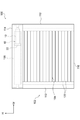
シャッタ装置100は、建築物の窓に取り付けられる窓シャッタであって、図6に示されるように、フレーム102、巻取体106、シャッタカーテン104、及び開閉装置10を備えている。
(Shutter device)
The
〔フレーム102〕
フレーム102は、一対のガイドレール112、シャッタケース114、及び下枠116を備えている。
[Frame 102]
The
一対のガイドレール112は、装置上下方向に夫々延びており、装置幅方向において窓の開口の両側に離間して配置されている。さらに、一対のガイドレール112は、シャッタカーテン104の両端部を装置奥行方向から夫々挟んでいる。そして、一対のガイドレール112は、上下移動するシャッタカーテン104を案内するようになっている。
The pair of
シャッタケース114は、一対のガイドレール112の上端を連結するように、装置幅方向に延びて配置されている。そして、シャッタケース114において装置幅方向に直交した方向で切断した断面は、矩形筒状とされており、シャッタケース114の内部は、空洞とされている。また、下枠116は、一対のガイドレール112の下端を連結するように、装置幅方向に延びて配置されている。
The
〔巻取体106、シャッタカーテン104〕
巻取体106は、 装置幅方向に延びた筒状とされており、シャッタケース114の内部に配置されている。さらに、巻取体106は、装置幅方向に延びた回転軸周りに回転するように支持されている。
[
The
シャッタカーテン104は、フレーム102で囲まれた矩形の開口を開閉するように配置されている。このシャッタカーテン104は、装置幅方向に延びた帯状のスラット122を複数備え、装置上下方向に並べられ複数のスラット122が互いに連結されることで形成されている。そして、上端部のスラット122が、巻取体106に取り付けられている。
The
この構成において、巻取体106が正方向に回転することで、窓の開口を閉塞しているシャッタカーテン104が、一対のガイドレール112に案内されながら巻取体106に巻き取られる。そして、窓の開口が開放される。これに対して、巻取体106が逆方向に回転することで、窓の開口を開放しているシャッタカーテン104が、一対のガイドレール112に案内されながら巻取体106から巻き出される。そして、窓の開口が閉塞される。
In this configuration, the
〔開閉装置10〕
開閉装置10は、シャッタケース114の内部に配置されており、巻取体106を介してシャッタカーテン104を上下移動させることで窓の開口を開閉するようになっている。なお、開閉装置10については、詳細を後述する。
[Switchgear 10]
The opening /
(要部構成)
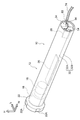
開閉装置10は、図6に示されるように、シャッタケース114の内部で、かつ、少なくとも一部が筒状の巻取体106の装置幅方向に一方側(図中右側)の内部に配置されている。そして、開閉装置10は、図2、図3に示されるように、筐体12、駆動モータ16、減速機構18、回転伝達部材22、制御基板26、及び受信装置28(所謂無縁モジュール)を備えている。
(Main part composition)
As shown in FIG. 6, the
〔筐体12〕
筐体12は、装置幅方向に延びた円筒状の本体部32と、本体部32の装置幅方向の一方側(図中右側)の開口を閉塞する厚肉の略円板状の閉塞部材34とを備えている。
[Case 12]
The
−本体部32−
本体部32は、図2、図3に示されるように、上下方向に分割することが出来るようになっており、本体部32の上方部分を形成すると共に下方が開口した断面半円状の上方部材32Aと、本体部32の下方部分を形成すると共に上方が開口した断面半円状の下方部材32Bとを備えている。
-Main body 32-
As shown in FIGS. 2 and 3, the
上方部材32A、及び下方部材32Bは、金属材料で形成されている。そして、上方部材32Aの装置幅方向に延びた一対の縁部と、下方部材32Bの装置幅方向に延びた一対の縁部とを装置上下方向に重ねた状態で、上方部材32Aと下方部材32Bとが、図示せぬ取付部材によって取り付けられることで、本体部32が形成されている。
The
−閉塞部材34−
閉塞部材34は、弾性材料であるゴム材料によって形成されている。ここで、弾性材料とは、アスカー硬度60〔度〕以下で、かつ、30〔度〕以上の材料である。なお、アスカー硬度とは、高分子計器株式会社のアスカー硬度計C型を用いて測定することができる。なお、閉塞部材34は、ゴム材料に代えて、ウレタン樹脂等の弾性を有する合成樹脂を用いてもよい。
-Closing member 34-
The closing
閉塞部材34は、図1、図4に示されるように、板面が装置幅方向を向いた円盤状とされており、無負荷状態の閉塞部材34の外径は、本体部32の内径と比して僅かに大きくされている。また、閉塞部材34において装置幅方向の一方側(図中右側)を向いた面には、閉塞部材34の径方向に延びると共に閉塞部材34の径方向を向いた段差面36が形成されている。
As shown in FIGS. 1 and 4, the closing
さらに、閉塞部材34には、この段差面36を境に、肉厚が比較的薄い薄肉部38と肉厚が比較的厚い厚肉部40とが形成されている。具体的には、段差面36は、段差面36に対して直交する方向(法線方向)から見て、閉塞部材34の径方向に延びた矩形状とされている。そして、段差面36は、装置幅方向に離間する一対の縁辺36A、36Bと、閉塞部材34の径方向に離間する一対の縁辺36Cとに囲まれている。この縁辺36Aは、薄肉部38において装置幅方向の一方側を向いた外表面38Aに形成され、縁辺36Bは、厚肉部40において装置幅方向の一方側を向いた外表面40Aに形成されている。
Further, the closing
また、薄肉部38には、図5に示されるように、薄肉部38の表裏を貫通する貫通孔38Bが形成されている。この貫通孔38Bは、装置幅方向から見て、縁辺36Aに対して傾斜する傾斜方向に延びた矩形状とされている。さらに、薄肉部38には、薄肉部38の表裏を貫通する貫通孔38Cが形成されている。この貫通孔38Cは、装置幅方向から見て、円形状とされており、貫通孔38Bに対して貫通孔38Bの長手方向の隣りに配置されている。
Further, as shown in FIG. 5, the thin-
また、厚肉部40には、後述するアンテナ線54を保持する保持部42と、後述する電源線60を保持する切欠部40Bとが形成されている。
Further, the
−保持部42−
この保持部42は、縁辺36Bの中央側の部分で、縁辺36Bに沿って形成されている。具体的には、保持部42は、厚肉部40の外表面40Aから突出した直方体状の突出部とされている。そして、保持部42には、装置幅方向から見て、縁辺36Bと交差する方向に延びている溝部42Aが形成されている。この溝部42Aに後述するアンテナ線54を嵌め込むことで、保持部42は、アンテナ線54を弾性力で挟持した状態で保持するようになっている(図1参照)。なお、溝部42Aの溝幅寸法は、アンテナ線54の外径寸法よりも小さく設定されている。
-Holding part 42-
The holding
−切欠部40B−
また、切欠部40Bは、装置幅方向から見て、保持部42を挟んで薄肉部38の貫通孔38Bの反対側で、円弧状に形成されている。そして、切欠部40Bは、閉塞部材34の径方向の外側へ開口している。この切欠部40Bに後述する電源線60を、閉塞部材34の径方向の外側から嵌め込むことで、切欠部40Bが、電源線60を保持するようになっている(図1参照)。
図1に示すように、本実施形態では、切欠部40Bと後述する受信装置28におけるアンテナ線54の挿通孔との中間位置に保持部42が設けられている。
-
Further, the
As shown in FIG. 1, in the present embodiment, the holding
〔制御基板26〕
制御基板26は、図2、図3に示されるように、筐体12の内部で、下方部材32Bの装置幅方向の中央側の部分に取り付けられている。制御基板26は、上方から見て、装置幅方向に延びた矩形状とされており、制御基板26には、駆動モータ16の駆動制御を行う駆動制御回路(符号省略)が実装されている。
[Control board 26]
As shown in FIGS. 2 and 3, the
さらに、制御基板26には、各部(駆動モータ16、制御基板26、受信装置28等の電力を使用する機器)に電力を供給するための電源線60の基端と、後述する受信装置28から伝送された制御信号を駆動制御回路に入力するための信号配線64の基端とが接続されている。また、この信号配線64の先端には、信号配線64を受信装置28と接続するためのコネクタ66が取り付けられている。
Further, the
〔駆動モータ16、減速機構18、回転伝達部材22〕
駆動モータ16、減速機構18、回転伝達部材22は、図2、図3に示されるように、制御基板26に対して装置幅方向の他方側(図中左側)に配置されており、装置幅方向の一方側から他方側へこの順番で配置されている。
[Drive
As shown in FIGS. 2 and 3, the
駆動モータ16は、筐体12の内部で、下方部材32Bに取り付けられており、駆動モータ16の出力軸(図示省略)は、装置幅方向の他方側に突出している。
The
減速機構18は、筐体12の内部で、下方部材32Bに取り付けられており、減速機構18には、駆動モータ16の出力軸が接続されている。そして、減速機構18は、駆動モータ16から伝達された回転の回転数を減少させ、かつ、駆動モータ16から伝達された回転のトルクを増大させて回転伝達部材22に伝達するようになっている。
The
回転伝達部材22は、装置幅方向において筐体12の他方側から筐体12の外部へ露出しており、回転伝達部材22には、減速機構18の出力軸が接続されている。そして、回転伝達部材22は、円盤状とされており、回転伝達部材22の外径は、筐体12の外径と比して大きくされている。また、回転伝達部材22の外周面には、4個の駆動溝22Aが、周方向に同様の間隔で形成されている。この駆動溝22Aは、巻取体106(図6参照)の内周面に形成された被駆動部(図示省略)に係合するようになっている。
The
この構成において、駆動モータ16から出力された回転力は、減速機構18によって減速、かつ、増大されて、回転伝達部材22から巻取体106へと伝達される。そして、巻取体106が回転することで、シャッタカーテン104が、巻き出され、又は巻き取られることで、上下移動する。
In this configuration, the rotational force output from the
〔受信装置28〕
受信装置28(所謂無線モジュール)は、図2、図3に示されるように、筐体12を構成する閉塞部材34に取り付けられている。そして、受信装置28は、図5に示されるように、空洞とされた内部に電子部材(図示せず。一例として、受信回路基板等)を備えた本体部50と、本体部50の内部を閉塞する蓋部52と、アンテナ線54とを備えている。
[Receiver 28]
As shown in FIGS. 2 and 3, the receiving device 28 (so-called wireless module) is attached to the closing
−本体部50−
本体部50は、内部が空洞とされており、装置幅方向に延びた直方体状とされている。また、本体部50において、装置奥行方向に対して直交する方向に切断した断面形状は、装置幅方向から見て縁辺36Aに対して傾斜した傾斜方向に延びた矩形状とされている。具体的には、本体部50の断面形状は、装置幅方向から見て、閉塞部材34の薄肉部38に形成された貫通孔38Bと同様の矩形状とされている。
-Main body 50-
The
そして、本体部50において装置幅方向の一方側の部分で、電子部品を挿入するために本体部50の内部が開放されている。また、本体部50において装置幅方向の他方側の部分には、前述したコネクタ66が接続される接続部50Aが形成されている。
Then, the inside of the
−蓋部52−
蓋部52は、本体部50の内部を閉塞しており、板面が装置幅方向を向いた板状とされている。また、装置幅方向から見て、蓋部52の外形は、本体部50の全体を覆うように本体部50の外形と比して大きくされており、傾斜方向に延びた矩形状とされている。
-Cover 52-
The
そして、蓋部52において本体部50を覆う部分には、送信機(所謂操作リモコン)を受信装置28に登録するための登録スイッチ52Aと、登録状況等を知らせるステータスランプ52Bとが設けられている。さらに、蓋部52において本体部50を覆う部分には、アンテナ線54が通る貫通孔52Cが形成されている。また、蓋部52において本体部50から突出した部分には、装置幅方向において閉塞部材34の貫通孔38Cと重なると共に蓋部52の表裏を貫通する円形状の貫通孔52Dが形成されている。
A
−アンテナ線54−
アンテナ線54は、本体部50の内部から蓋部52の貫通孔52Cを通って外部に延設されており、外部に延設されたアンテナ線54の先端(切断端)には、先端を保護する保護キャップ54Aが取り付けられている。保護キャップ54Aは、一例として合成樹脂材料で形成することができ、図示しない孔にアンテナ線54の先端を挿入して、接着剤にて固定することができる。これにより、アンテナ線54の中に水が浸入して内部の銅線が腐食{錆びる)することが抑制できる。また、保護キャップ54Aを取り付けることで、アンテナ線54の内部の銅線が外部に露出しないので、作業者等が銅線に触れることを抑制できる。そして、アンテナ線54は、送信機を操作することにより無線で送信された制御信号を受信するようになっている。
-Antenna wire 54-
The
なお、受信装置28の内部において、アンテナ線54の基端は、図示しない電子部材(図示せず。一例として、受信回路基板等)に接続されている。アンテナ線54と電子部材とは、コネクタで接続されていてもよく、半田付けで接続されていてもよく、その他の公知の方法で接続されていてもよい。
Inside the receiving
この構成において、受信装置28の本体部50が、図4、図5に示されるように、閉塞部材34の薄肉部38の外表面38A側から貫通孔38Bに挿入される。そして、蓋部52が、薄肉部38の外表面38Aに重なる。この状態で、装置幅方向から見て、薄肉部38の貫通孔38Cと、蓋部52の貫通孔52Dとは重なっている。
In this configuration, the
また、閉塞部材34が本体部32の装置幅方向の一方側の開口を閉塞した状態では、閉塞部材34に取り付けられた受信装置28は、筐体12の内部に配置されている。ここで、受信装置28が筐体12の内部に配置される状態とは、受信装置28が円筒状の本体部32で囲まれている状態である。
Further, in a state where the closing
〔その他〕
開閉装置10は、図4、図5に示されるように、受信装置28を閉塞部材34に取り付けるためのカヌータイプの樹脂クリップ70を備えている。具体的には、樹脂クリップ70を、蓋部52の貫通孔52D、及び薄肉部38の貫通孔38Cにこの順番に差し込むことで、受信装置28は、閉塞部材34に取り付けられる。
〔others〕
As shown in FIGS. 4 and 5, the
(作用)
以上の構成において、図1に示されるように、閉塞部材34に取り付けられた受信装置28の接続部50Aに、信号配線64の先端に取り付けられたコネクタ66が接続される。
(Action)
In the above configuration, as shown in FIG. 1, the
さらに、閉塞部材34に取り付けられた受信装置28のアンテナ線54の一部が、閉塞部材34の厚肉部40に形成された保持部42の溝部42Aに嵌め込まれることで、保持部42が、アンテナ線54の中間部分を弾性力で保持する。また、基端が制御基板26に接続された電源線60の一部が、閉塞部材34の径方向の外側から切欠部40Bに嵌め込まれることで、閉塞部材34が、電源線60を保持する。
Further, a part of the
さらに、電源線60において閉塞部材34から筐体12の外部に延びている部分と、アンテナ線54において保持部42から筐体12の外部に延びている部分とは、配線保護材74を用いて束ねられている。
Further, in the
このように、本実施形態の開閉装置10によれば、受信装置28から外部へ延設されるアンテナ線54の中間部を保持部42で保持することができるため、アンテナ線54を電源線60に沿って這わせる作業、及び電源線60とアンテナ線54とを束ねる作業前にアンテナ線54の中間部を保持部42で保持しておけば、アンテナ線54を電源線60に沿って這わせる作業、及び電源線60とアンテナ線54とを束ねる作業において、仮にアンテナ線54が引っ張られた場合においても、受信装置28におけるアンテナ線54の接続部分(受信装置28の内部の図示しない基板とアンテナ線54との接続部分)に不要な張力が作用することを抑制でき、電源線60とアンテナ線54とを束ねる作業が容易になる。また、アンテナ線54を保持するには、アンテナ線54を溝部42Aに押し込んで嵌め込むだけでよいため、作業が容易である。
As described above, according to the opening /
さらに、本実施形態の開閉装置10によれば、保持部42が、受信装置28と切欠部40Bとの中間に設けられているため、受信装置28から延設されたアンテナ線54を、受信装置28と切欠部40Bとの中間に設けた保持部42を経由して、最短距離で電源線60に到達させることができる。
Further, according to the
また、閉塞部材34が、下方部材32Bの装置幅方向の一方側の部分に配置される。そして、上方部材32Aの装置幅方向に延びた一対の縁部と、下方部材32Bの装置幅方向に延びた一対の縁部とを装置上下方向に重ねた状態で、上方部材32Aと下方部材32Bとを、図示せぬ取付部材によって取り付ける。
Further, the closing
そして、開閉装置10は、図6に示されるように、シャッタケース114の内部で、かつ、少なくとも一部が筒状の巻取体106の装置幅方向に一方側(図中右側)の内部に配置されている。
Then, as shown in FIG. 6, the
この状態で、シャッタ装置100の外部から送信機を操作することにより無線で送信された制御信号を、受信装置28はアンテナ線54を介して受信する。制御信号を受信した受信装置28は、信号配線64を介して制御信号を制御基板26に実装された駆動制御回路へ伝送する。また、制御基板26に実装された駆動制御回路が、駆動モータ16を回転させ、駆動モータ16から出力された回転力は、減速機構18によって減速、かつ、増大されて、回転伝達部材22から巻取体106へと伝達される。そして、巻取体106が回転することで、シャッタカーテン104が、巻き出され、又は巻き取られることで、上下移動する。
In this state, the receiving
(まとめ)
以上説明したように、受信装置28は、筐体12の閉塞部材34に取り付けられている。このため、受信装置28が筐体12の外部で筐体12とは離間した場所に取り付けられる場合と比して、筐体12の外部の空間を有効に活用することができる。
(summary)
As described above, the receiving
また、アンテナ線54は、開閉装置10の外部に延設されているので、開閉装置10の内部(巻かれたシャッタカーテン104の内部)に配置された場合に比較して、受信性能を向上させることができる。
Further, since the
また、アンテナ線54は、電源線60と共に配線保護材74を用いて束ねられているので、シャッタ装置100を建築物の窓に取り付ける際に、電源線60とアンテナ線54とを個別に配設(引き回し)する場合に比較して、配設作業が1回で済み、配設作業が容易になる。
Further, since the
また、アンテナ線54、及び電源線60は、配線保護材74で保護されているので、例えば、これらを挿通する孔(一例として、図示しないシャッタケース114に形成されている)に保護材(ブッシング)を取り付ける必要が無くなる。これにより、部品点数を削減することができる。
Further, since the
また、受信装置28は、信号配線64を介して制御基板26の駆動制御回路と接続されている。受信装置28が、制御基板26に直接取り付けられる場合と比して、受信装置28を介して制御基板26にかかる振動等の負荷を軽減することができる。
Further, the receiving
また、受信装置28は、筐体12の内部に配置されている。このため、受信装置28が、筐体12の外部に配置されている場合と比して、雨水等の液体が受信装置28に付着するのを抑制することができる。
Further, the receiving
また、受信装置28と、信号配線64のコネクタ66と、受信装置28の接続部50Aとは、筐体12の内部に配置されている。このため、コネクタ66と接続部50Aとを接続する部分が筐体12の外部である場合と比して、外力によりコネクタ66と接続部50Aとの接続が解除されるのを抑制することができる。
Further, the receiving
また、閉塞部材34は、弾性材料で形成されている。このため、筐体12に衝撃が加わって筐体12が振動した場合でも、閉塞部材34が振動を吸収することで、受信装置28に振動が伝達されるのを抑制することができる。
Further, the closing
また、閉塞部材34は、弾性材料で形成されている。このため、閉塞部材34に形成された切欠部40Bの周面を電源線60に押し付けることで、切欠部40Bと電源線60との間から筐体12の内部に液体が浸入するのを抑制することができる。
Further, the closing
また、閉塞部材34は、弾性材料(ゴム材料)で形成されている。このため、閉塞部材34が金属で形成されている場合と比して、筐体12の内部に配置された受信装置28の電波特性の低下を抑制することができる。
Further, the closing
また、受信装置28は、樹脂クリップ70を用いて閉塞部材34に取り付けられている。このため、ネジ等を用いて取り付ける場合と比して、受信装置28を容易に閉塞部材34に取り付けることができる。
Further, the receiving
また、シャッタ装置100においては、開閉装置10を備えることで、シャッタ装置の内部の空間を有効に活用することができる。
Further, in the
[その他の実施形態]
なお、本発明を特定の実施形態について詳細に説明したが、本発明は係る実施形態に限定されるものではなく、本発明の範囲内にて他の種々の実施形態をとることが可能であることは当業者にとって明らかである。
[Other Embodiments]
Although the present invention has been described in detail with respect to specific embodiments, the present invention is not limited to such embodiments, and various other embodiments can be taken within the scope of the present invention. That is clear to those skilled in the art.
また、上記実施形態では、閉塞部材34は、弾性材料で形成されたが、例えば、閉塞部材が金属材料で形成されてもよい。この場合には、保持部42は、弾性材料で形成することが好ましい。
Further, in the above embodiment, the closing
上記実施形態では、保持部42が閉塞部材34の略中央部に設けられていたが、保持部42は、閉塞部材34の中央部以外の部位に設けてもよい。
In the above embodiment, the holding
上記実施形態の開閉装置10は、受信装置28を備えていたが、送信装置を備えていてもよく、アンテナ線54は該送信装置に接続されていてもよい。
Although the
なお、図7(A)、(B)に示すように、受信装置28の本体部50と蓋部52との接合部分62にアンテナ線54が通る貫通孔52Cを形成すると共に、アンテナ線54を屈曲させた状態で本体部50と蓋部52との間でアンテナ線54を挟持固定ための凹凸部68を本体部50、及び蓋部52に形成してする構成としてもよい。
As shown in FIGS. 7A and 7B, a through
これにより、受信装置28において、アンテナ線54と図示しない電子部材(受信回路基板等)との接続部分に不要な張力を作用させない効果が得られ、アンテナ線54の抜けを抑制することができる。また、アンテナ線54の抜けを抑制するためのストッパー、インシュロック(結束バンド)、ブッシング等の別部品が不要となる。
As a result, in the receiving
上記実施形態では、特に説明しなかったが、開閉装置10を用いることで、既存の手動シャッタを、容易に電動シャッタに変えることができる。
Although not particularly described in the above embodiment, the existing manual shutter can be easily changed to an electric shutter by using the
10 開閉装置
12 筐体
16 駆動モータ(モータの一例)
26 制御基板(駆動制御回路)
28 受信装置(通信装置の一例)
34 閉塞部材(取付部材の一例)
40B 切欠部(挿通部の一例)
42 保持部
42A 溝部
54 アンテナ線
60 電源線
100 シャッタ装置
104 シャッタカーテン
106 巻取体
10
26 Control board (drive control circuit)
28 Receiver (an example of communication device)
34 Closing member (example of mounting member)
40B notch (an example of insertion part)
42
54
Claims (4)
前記シャッタカーテンを巻き取る巻取体の内部に少なくとも一部が配置され、かつ開口部を有する筐体と、
電源線挿通用の挿通部が貫通して設けられ、取り付けられたときに外側となる外側部にアンテナ線保持用の保持部が形成され、かつ前記筐体の前記開口部を閉塞するように前記筐体に取り付けられた取付部材と、
前記筐体の内部に取り付けられ、前記取付部材の前記挿通部を挿通する電源線を通して前記巻取体を回転させる回転力を発生する電力が供給されるモータと、
前記取付部材に取り付けられた通信装置であって、中間部が前記取付部材の前記保持部に保持されたアンテナ線を有し、送信機から無線で送信された制御信号を前記アンテナ線を介して受信し、かつ前記モータの駆動制御を行なう駆動制御回路に受信した制御信号を伝送する通信装置と、
を含む開閉装置。 A switchgear that moves the shutter curtain to open and close the opening of a structure.
A housing in which at least a part of the winding body for winding the shutter curtain is arranged and has an opening.
The insertion portion for inserting the power supply line is provided through the insertion portion, and the holding portion for holding the antenna wire is formed on the outer portion which becomes the outer side when attached, and the opening of the housing is closed. The mounting member attached to the housing and
A motor that is mounted inside the housing and is supplied with electric power that generates a rotational force that rotates the winding body through a power supply line that inserts the insertion portion of the mounting member.
A communication device attached to the mounting member, the intermediate portion having an antenna wire held by the holding portion of the mounting member, and a control signal wirelessly transmitted from a transmitter via the antenna wire. A communication device that receives and transmits the received control signal to the drive control circuit that controls the drive of the motor.
Switchgear including.
前記保持部は、前記アンテナ線を挟持する溝部が形成されて前記取付部材の前記外側部から突出した突出部である、請求項1に記載の開閉装置。 The mounting member is made of an elastic material and is made of an elastic material.
The switchgear according to claim 1, wherein the holding portion is a protruding portion having a groove portion for sandwiching the antenna wire and projecting from the outer portion of the mounting member.
請求項1〜請求項3の何れか1項に記載の開閉装置と、
を備えたシャッタ装置。 Shutter curtain and
The switchgear according to any one of claims 1 to 3.
Shutter device equipped with.
Priority Applications (1)
| Application Number | Priority Date | Filing Date | Title |
|---|---|---|---|
| JP2018095121A JP6936768B2 (en) | 2018-05-17 | 2018-05-17 | Switchgear, shutter device |
Applications Claiming Priority (1)
| Application Number | Priority Date | Filing Date | Title |
|---|---|---|---|
| JP2018095121A JP6936768B2 (en) | 2018-05-17 | 2018-05-17 | Switchgear, shutter device |
Publications (2)
| Publication Number | Publication Date |
|---|---|
| JP2019199753A JP2019199753A (en) | 2019-11-21 |
| JP6936768B2 true JP6936768B2 (en) | 2021-09-22 |
Family
ID=68612951
Family Applications (1)
| Application Number | Title | Priority Date | Filing Date |
|---|---|---|---|
| JP2018095121A Active JP6936768B2 (en) | 2018-05-17 | 2018-05-17 | Switchgear, shutter device |
Country Status (1)
| Country | Link |
|---|---|
| JP (1) | JP6936768B2 (en) |
Family Cites Families (4)
| Publication number | Priority date | Publication date | Assignee | Title |
|---|---|---|---|---|
| JPH1181819A (en) * | 1997-09-08 | 1999-03-26 | Sanwa Shutter Corp | Mounting metal fitting of bracket |
| FR2913132B1 (en) * | 2007-02-22 | 2010-05-21 | Somfy Sas | RADIO CONTROL DEVICE, ELECTRIC ACTUATOR AND DOMOTIC INSTALLATION COMPRISING SUCH A DEVICE |
| JP6238048B2 (en) * | 2013-07-25 | 2017-11-29 | アイシン精機株式会社 | Electric shutter drive device |
| JP6805020B2 (en) * | 2016-05-20 | 2020-12-23 | 株式会社フジクラ | Antenna device and its manufacturing method |
-
2018
- 2018-05-17 JP JP2018095121A patent/JP6936768B2/en active Active
Also Published As
| Publication number | Publication date |
|---|---|
| JP2019199753A (en) | 2019-11-21 |
Similar Documents
| Publication | Publication Date | Title |
|---|---|---|
| EP3314782B1 (en) | A rotatable antenna apparatus | |
| US7812492B2 (en) | Motor drive assembly | |
| JP6238048B2 (en) | Electric shutter drive device | |
| JP6936768B2 (en) | Switchgear, shutter device | |
| JP2007261503A (en) | Mounting bracket of on-vehicle camera | |
| JP6204210B2 (en) | Motor unit, motor with reduction mechanism, and sliding door automatic opening / closing device | |
| JP6215480B2 (en) | Motor device with reduction mechanism | |
| CN108322629B (en) | Camera assembly and electronic equipment | |
| JP7036402B2 (en) | Switchgear, shutter device | |
| US10082193B2 (en) | Actuator | |
| JP6936767B2 (en) | Switchgear and shutter device | |
| PL206926B1 (en) | Winding device | |
| EP3629436A1 (en) | Flat cable winding device and flat cable routing structure | |
| WO2018088136A1 (en) | Vehicular wire-type window regulator | |
| WO2021079963A1 (en) | Drive device and window glass lifting device | |
| JP2016058352A (en) | Rotary connector device | |
| JP2020097981A (en) | Drain valve driving device | |
| JP2020097982A (en) | Drain valve driving device | |
| JP2010045890A (en) | Geared outer-rotor brushless motor | |
| EP1990500A1 (en) | Cord seat assembly | |
| KR20110096324A (en) | The structure of a flying mechanism | |
| WO2016009623A1 (en) | Electricity-generating device | |
| JP7059480B2 (en) | Electric shutter drive device | |
| WO2008036436A3 (en) | A window treatment system with a single cord | |
| KR20140086806A (en) | Display case for fishing reel and fishing reel |
Legal Events
| Date | Code | Title | Description |
|---|---|---|---|
| A711 | Notification of change in applicant |
Free format text: JAPANESE INTERMEDIATE CODE: A711 Effective date: 20201014 |
|
| A621 | Written request for application examination |
Free format text: JAPANESE INTERMEDIATE CODE: A621 Effective date: 20201111 |
|
| A977 | Report on retrieval |
Free format text: JAPANESE INTERMEDIATE CODE: A971007 Effective date: 20210805 |
|
| TRDD | Decision of grant or rejection written | ||
| A01 | Written decision to grant a patent or to grant a registration (utility model) |
Free format text: JAPANESE INTERMEDIATE CODE: A01 Effective date: 20210817 |
|
| A61 | First payment of annual fees (during grant procedure) |
Free format text: JAPANESE INTERMEDIATE CODE: A61 Effective date: 20210827 |
|
| R150 | Certificate of patent or registration of utility model |
Ref document number: 6936768 Country of ref document: JP Free format text: JAPANESE INTERMEDIATE CODE: R150 |