EP3629436A1 - Flat cable winding device and flat cable routing structure - Google Patents
Flat cable winding device and flat cable routing structure Download PDFInfo
- Publication number
- EP3629436A1 EP3629436A1 EP19193569.1A EP19193569A EP3629436A1 EP 3629436 A1 EP3629436 A1 EP 3629436A1 EP 19193569 A EP19193569 A EP 19193569A EP 3629436 A1 EP3629436 A1 EP 3629436A1
- Authority
- EP
- European Patent Office
- Prior art keywords
- flat cable
- flat
- flat cables
- cables
- winding device
- Prior art date
- Legal status (The legal status is an assumption and is not a legal conclusion. Google has not performed a legal analysis and makes no representation as to the accuracy of the status listed.)
- Granted
Links
- 238000004804 winding Methods 0.000 title claims abstract description 120
- 230000002093 peripheral effect Effects 0.000 claims abstract description 37
- 238000000926 separation method Methods 0.000 claims abstract description 23
- 238000010521 absorption reaction Methods 0.000 claims abstract description 21
- 230000001012 protector Effects 0.000 description 16
- 230000002411 adverse Effects 0.000 description 3
- 230000000694 effects Effects 0.000 description 3
- 238000013459 approach Methods 0.000 description 2
- 238000003780 insertion Methods 0.000 description 2
- 230000037431 insertion Effects 0.000 description 2
- 238000005452 bending Methods 0.000 description 1
- 230000005540 biological transmission Effects 0.000 description 1
- 230000006835 compression Effects 0.000 description 1
- 238000007906 compression Methods 0.000 description 1
- 239000004020 conductor Substances 0.000 description 1
- 238000012986 modification Methods 0.000 description 1
- 230000004048 modification Effects 0.000 description 1
- 229920005989 resin Polymers 0.000 description 1
- 239000011347 resin Substances 0.000 description 1
- 238000005096 rolling process Methods 0.000 description 1
- 229920003002 synthetic resin Polymers 0.000 description 1
- 239000000057 synthetic resin Substances 0.000 description 1
Images


Classifications
-
- H—ELECTRICITY
- H02—GENERATION; CONVERSION OR DISTRIBUTION OF ELECTRIC POWER
- H02G—INSTALLATION OF ELECTRIC CABLES OR LINES, OR OF COMBINED OPTICAL AND ELECTRIC CABLES OR LINES
- H02G11/00—Arrangements of electric cables or lines between relatively-movable parts
- H02G11/02—Arrangements of electric cables or lines between relatively-movable parts using take-up reel or drum
-
- B—PERFORMING OPERATIONS; TRANSPORTING
- B60—VEHICLES IN GENERAL
- B60R—VEHICLES, VEHICLE FITTINGS, OR VEHICLE PARTS, NOT OTHERWISE PROVIDED FOR
- B60R16/00—Electric or fluid circuits specially adapted for vehicles and not otherwise provided for; Arrangement of elements of electric or fluid circuits specially adapted for vehicles and not otherwise provided for
- B60R16/02—Electric or fluid circuits specially adapted for vehicles and not otherwise provided for; Arrangement of elements of electric or fluid circuits specially adapted for vehicles and not otherwise provided for electric constitutive elements
- B60R16/0207—Wire harnesses
- B60R16/0215—Protecting, fastening and routing means therefor
-
- B—PERFORMING OPERATIONS; TRANSPORTING
- B60—VEHICLES IN GENERAL
- B60R—VEHICLES, VEHICLE FITTINGS, OR VEHICLE PARTS, NOT OTHERWISE PROVIDED FOR
- B60R16/00—Electric or fluid circuits specially adapted for vehicles and not otherwise provided for; Arrangement of elements of electric or fluid circuits specially adapted for vehicles and not otherwise provided for
- B60R16/02—Electric or fluid circuits specially adapted for vehicles and not otherwise provided for; Arrangement of elements of electric or fluid circuits specially adapted for vehicles and not otherwise provided for electric constitutive elements
- B60R16/023—Electric or fluid circuits specially adapted for vehicles and not otherwise provided for; Arrangement of elements of electric or fluid circuits specially adapted for vehicles and not otherwise provided for electric constitutive elements for transmission of signals between vehicle parts or subsystems
- B60R16/027—Electric or fluid circuits specially adapted for vehicles and not otherwise provided for; Arrangement of elements of electric or fluid circuits specially adapted for vehicles and not otherwise provided for electric constitutive elements for transmission of signals between vehicle parts or subsystems between relatively movable parts of the vehicle, e.g. between steering wheel and column
-
- B—PERFORMING OPERATIONS; TRANSPORTING
- B65—CONVEYING; PACKING; STORING; HANDLING THIN OR FILAMENTARY MATERIAL
- B65H—HANDLING THIN OR FILAMENTARY MATERIAL, e.g. SHEETS, WEBS, CABLES
- B65H75/00—Storing webs, tapes, or filamentary material, e.g. on reels
- B65H75/02—Cores, formers, supports, or holders for coiled, wound, or folded material, e.g. reels, spindles, bobbins, cop tubes, cans, mandrels or chucks
- B65H75/34—Cores, formers, supports, or holders for coiled, wound, or folded material, e.g. reels, spindles, bobbins, cop tubes, cans, mandrels or chucks specially adapted or mounted for storing and repeatedly paying-out and re-storing lengths of material provided for particular purposes, e.g. anchored hoses, power cables
- B65H75/38—Cores, formers, supports, or holders for coiled, wound, or folded material, e.g. reels, spindles, bobbins, cop tubes, cans, mandrels or chucks specially adapted or mounted for storing and repeatedly paying-out and re-storing lengths of material provided for particular purposes, e.g. anchored hoses, power cables involving the use of a core or former internal to, and supporting, a stored package of material
- B65H75/44—Constructional details
- B65H75/4457—Arrangements of the frame or housing
-
- H—ELECTRICITY
- H01—ELECTRIC ELEMENTS
- H01B—CABLES; CONDUCTORS; INSULATORS; SELECTION OF MATERIALS FOR THEIR CONDUCTIVE, INSULATING OR DIELECTRIC PROPERTIES
- H01B7/00—Insulated conductors or cables characterised by their form
- H01B7/08—Flat or ribbon cables
-
- B—PERFORMING OPERATIONS; TRANSPORTING
- B65—CONVEYING; PACKING; STORING; HANDLING THIN OR FILAMENTARY MATERIAL
- B65H—HANDLING THIN OR FILAMENTARY MATERIAL, e.g. SHEETS, WEBS, CABLES
- B65H2701/00—Handled material; Storage means
- B65H2701/30—Handled filamentary material
- B65H2701/34—Handled filamentary material electric cords or electric power cables
Definitions
- the present invention relates to a flat cable winding device that stacks and winds a plurality of flat cables and a flat cable routing structure including the flat cable winding device.
- a vehicle such as an automobile includes a flat cable routing structure that connects a device on a movable body such as a slide seat or a slide door to a device such as a control device on a vehicle body by a plurality of flat cables to enable transmission of control signals and power supply.
- Such routing structure includes a flat cable winding device that winds excess length parts (surplus length parts) of the flat cables formed accompanying the slide of the movable body so that the flat cables do not interfere with the surroundings.
- Such flat cable winding device which winds one end of a flat cable and feeds the other end of the flat cable, may include a plurality of flat cables stacked and wound therein.
- a flat cable winding device 101 includes a central shaft portion 103 to which one end portions of a plurality of stacked flat cables 102 are fixed, a rotary table (also referred to as rotor) 104 that is rotatable around the central shaft portion 103, a plurality of rotatable rollers 105 on the rotary table 104 around the central shaft portion 103, and a biasing unit (not shown) such as a spring that rotates and biases the rotary table 104 in a winding direction R of flat cables.
- a biasing unit such as a spring that rotates and biases the rotary table 104 in a winding direction R of flat cables.
- the flat cable winding device 101 With rotation of the rotary table 104 in the winding direction R, the flat cable winding device 101 inverts one end side of the flat cables 102 guided into a case (not shown) of the winding device by a roller 105A of the plurality of rotatable rollers 105 and winds the one end side around the outer periphery of the central shaft portion 103 as well as around outer peripheries of the plurality of rotatable rollers 105.
- the rotary table 104 rotates in the direction opposite to the winding direction R, so that the flat cables 102 wound around the outer periphery of the central shaft portion 103 and the outer peripheries of the plurality of rollers 105 are released and fed out of the case of the winding device.
- the plurality of flat cables 102 wound along the rollers 105 has a linear inner periphery and approaches an arc as it goes to the outer periphery and thus slack occurs.
- the slack occurs between the winding device 101 and a movable body 106 due to a difference in wire length (wire length difference that the inner periphery is longer than the outer periphery) between the flat cable 102 on the inner peripheral side and a flat cable on the outer peripheral side during winding.
- This slack part of the flat cable 102 may interfere with and damage the surroundings.
- a flat cable routing structure as shown in Fig. 6 is proposed to remove the slack of the flat cable located at the inner peripheral side that occurs during winding.
- a flat cable routing structure 210 which is described in JP-A-2017-189040 , includes a plurality of flat cables 220, a winding device 230 that winds the flat cables 220 in a stacked state, and a slide protector 240 that is provided at an end portion of the flat cables 220 pulled out from the winding device 230 and joined to a power supply target device 250.
- the flat cable routing structure 210 further includes, in the slide protector 240, a slack absorption unit 260 for the flat cables 220.
- the slack absorption unit 260 includes a wire length difference accommodating case 261 that accommodates a wire length difference part in the vicinity of the end portion of the flat cables 220, and a curved portion 263 that is curved in a direction opposite to the winding direction via the winding device 230 for the wire length difference part of the flat cables 220 in the wire length difference accommodating case 261.
- the slack absorption unit is provided in the slide protector that is joined to a movable body. For this reason, the configuration on the moving body side may be complicated.
- the present invention is made in view of the above-described circumstance, and an object thereof is to provide a flat cable winding device capable of removing slack occurring in a flat cable on an inner peripheral side during winding of a plurality of flat cables while simplifying a configuration on a moving body side, and a flat cable routing structure including the flat cable winding device.
- the separation guide path provided in the case of the winding device guides the flat cables guided into the case from the flat cable guide portion separately to the winding start position of the rollers.
- the slack absorption unit provided in the intermediate part of the separation guide path absorbs the slack of the flat cable on the inner peripheral side that is generated when the plurality of flat cables are stacked and wound. Therefore, an adverse effect due to the slack of the flat cable can be eliminated.
- the slack absorption unit is provided in the case of the winding device, and accordingly the slack of the flat cable on the inner peripheral side can be prevented from coming out of the case of the winding device.
- the flat cables are guided to the winding start position of the rollers by the guide members provided in the separation guide path. Accordingly, the plurality of flat cables can be separately guided to the rollers. Further, the slack can be removed with a simple configuration, since the member that guides the flat cable on the inner peripheral side is the movable guide member of the guide members and the tension for removing the slack is applied to the flat cable on the inner peripheral side by an elastic member via the movable guide member.
- the guide members are constituted by a guide roller. Therefore, the slack can be removed with a simple configuration while the flat cables are wound or fed out by the flat cable winding device further smoothly.
- the slack absorption unit provided in the case of the winding device absorbs the slack of the flat cable on the inner peripheral side that is generated when the plurality of flat cables are stacked and wound. Therefore, an adverse effect due to the slack of the flat cable can be eliminated. Particularly, since the slack of the flat cable on the inner peripheral side can be prevented from coming out of the case of the winding device, it is not necessary to provide a slack absorption unit near the slide protector side that slides together with a movable body and the configuration of the movable body can be simplified. Further, no excess stress is applied to the flat cables since there is no difference in wire length (no slack) therebetween when the flat cables are guided out of the case of the winding device to the outside.
- slack occurring in a flat cable on an inner peripheral side can be removed during winding of a plurality of flat cables while simplifying a configuration on a moving body side.
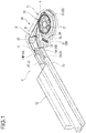
- Fig. 1 is a perspective view showing a schematic configuration of a flat cable winding device and a flat cable routing structure according to the embodiment of the present invention.
- Fig. 2 is a plan view showing the schematic configuration of the flat cable winding device and the flat cable routing structure.
- a flat cable routing structure 1 in this embodiment is a structure in an automobile or the like, which supplies power to a power supply object 50 such as an electronic device provided on a slide body (movable body) such as a slide seat or a slide door that is slidable with respect to the vehicle in the vehicle front-rear direction.
- a power supply object 50 such as an electronic device provided on a slide body (movable body) such as a slide seat or a slide door that is slidable with respect to the vehicle in the vehicle front-rear direction.
- the flat cable routing structure 1 is installed in the vicinity of a slide rail that slidably supports the slide body.
- the slide rail extends in the front-rear direction of the vehicle so that the slide body slides in the front-rear direction of the vehicle.
- a slide protector (movable body) 52 is joined and slides together with the slide body or the power supply object 50.
- the flat cable routing structure 1 includes a flat cable winding device 10 in which a plurality of (two in the present embodiment) flat cables 2 (2A, 2B) is wound whose one end sides are connected thereto and the other end sides are feedable therefrom.
- the other end sides of the flat cables 2 are connected to the power supply object 50 by a connector through the slide protector 52.
- the flat cable winding device 10 is fixed on a vehicle body side.
- the vehicle body is a fixed body. Therefore, the slide protector 52 reciprocates between a separated position where the flat cables 2 are fed out and separated from the flat cable winding device 10, and a close position where the flat cables 2 are wound and come close to the flat cable winding device 10.
- the flat cables 2 are sufficiently longer than a slide distance of the slide body such as a slide seat.
- the other end sides of the flat cables 2 pass through the inside of the flat cable winding device 10 and are drawn out to the outside to connect a connector on the vehicle body side.
- the flat cables 2, which are conductors covered with a resin, are thin strip plates having flexibility in the thickness direction (direction intersecting the flat surface).
- the width direction of the flat cables 2 is the vertical direction.
- the flat cable winding device 10 winds the flat cables 2 as the slide protector 52 approaches, and feeds the flat cables 2 as the slide protector 52 is separated. Accordingly, excess length parts of the flat cables 2 accompanying the slide of the slide body are wound so that the flat cables 2 do not interfere with the surroundings.
- the flat cable winding device 10 includes a case 11 formed of a synthetic resin that accommodates the wound flat cables 2.
- a winding unit 20 is provided on one end side and a separation guide path 30 is provided on the other end side.
- two flat cable guide portions 14 that introduce two flat cables 2 (2A, 2B) into the case 11 are provided in the same direction toward the slide protector 52.
- the two flat cable guide portions 14A, 14B are provided as separate parallel insertion holes in the present embodiment; however, they may be provided by dividing one insertion hole.
- the winding unit 20 is inside the case 11 at a position away from the flat cable guide portions 14.
- the winding unit 20 further includes a biasing unit (not shown) such as a spiral spring or a coil spring that rotates and biases the rotary table 22 in the winding direction R of flat cables, and a plurality of rollers 23 provided on the rotary table 22.
- the separation guide path 30 is provided in an internal space of the case 11 between the flat cable guide portions 14 and a winding start position P when the plurality of flat cables 2 is wound by the plurality of rollers 23 in a stacked state.
- the separation guide path 30 guides the flat cables 2 guided into the case 11 from the flat cable guide portions 14 to the winding start position P separately.
- a slack absorption unit 38 is provided to absorb slack of the flat cable 2A that is on an inner peripheral side when the flat cables 2 are stacked and wound around the plurality of rollers 23.
- the separation guide path 30 includes a plurality of guide rollers 31 to 34 that separately turns the plurality of flat cables 2 guided from the flat cable guide portions 14 into a direction orthogonal to the guide direction and guides the plurality of flat cables 2 to the winding start position P of the winding unit 20.
- the slack absorption unit 38 includes the movable roller 34 of the two rollers 33, 34 that guide the flat cable 2A on the inner peripheral side, and a slack absorption spring 37 that biases the movable roller 34.
- the movable roller 34 guides the flat cable 2A on the inner peripheral side along a bent path and is movable in a direction orthogonal to the flat surface of the flat cable 2A.
- a linear slide groove 35 is formed in the case 11 along a straight line halving the bending angle of the flat cable 2A that is in rolling contact with the movable roller 34, so that the rotation support shaft of the movable roller 34 slides along the slide groove 35.
- the movable roller 34 is biased by a slack absorption spring (compression spring) 37 inside a bent portion of the slide groove 35 as indicated by an arrow N toward the outside of the bent portion.
- a slack absorption spring (compression spring) 37 By applying an urging force to the movable roller 34 in this manner, tension for removing the slack can be applied to the flat cable 2A on the inner peripheral side via the movable roller 34.
- the moving direction of the movable roller 34 may not be perpendicular to the flat surface of the flat cable 2A, and may be any direction as long as the tension for removing the slack can be applied to the flat cable 2A on the inner peripheral side.
- the rotary table 22 is rotated in the winding direction R by an urging unit, so that the flat cables 2 are wound along the plurality of rollers 23. Accordingly, the flat cables 2 are pulled into the case 11 and accommodated therein.
- the two flat cables 2A, 2B wound along the rollers 23 have a linear inner periphery among the rollers 23 and an almost circular outer periphery that is bulged outward. That is, in the winding unit 20, the flat cable 2B on the outer peripheral side loosens outward with respect to the flat cable 2A on the inner peripheral side. Accordingly, the flat cable 2A on the inner peripheral side is longer than the flat cable 2B on the outer peripheral side at a position before being guided by the winding unit 20, which results in a wire length difference. For this reason, when the other ends of the flat cables 2A, 2B are fixed at the same position, slack occurs in the flat cable 2A on the inner peripheral side before the winding unit 20.
- the roller that bends and guides the flat cable 2A in which the slack occurs is the movable roller 34.
- the roller slides in a direction B by an urging force of the spring 37 along the slide groove 35 in the case 11.
- the spring 37 With the spring 37, the flat cable 2A is pulled toward the winding unit 20 while being tensioned in a direction in which the slack is absorbed. Therefore, no slack occurs in the flat cables 2A, 2B outside the case 11 of the flat cable winding device 10.
- the movable roller 34 slides in a direction of an arrow A against the urging force of the spring 37 in response to the tension acting on the flat cable 2A on the inner peripheral side. Accordingly, the flat cable 2A on the inner peripheral side is smoothly fed out to the outside of the case 11 without slack.
- the separation guide path 30 in the case 11 of the winding device 10 guides the flat cables 2 (2A, 2B) guided into the case 11 from the flat cable guide portions 14 separately to the winding start position P of the rollers 23.
- the slack absorption unit 38 provided in the intermediate part of the separation guide path 30 absorbs the slack of the flat cable 2A on the inner peripheral side that is generated when the plurality of flat cables 2 are stacked and wound. Therefore, an adverse effect due to the slack of the flat cable 2A can be eliminated.
- the slack absorption unit 38 is provided in the case 11 of the winding device, and accordingly the slack of the flat cable 2A on the inner peripheral side can be prevented from coming out of the case 11 of the winding device. Therefore, it is not necessary to provide a slack absorption unit near the slide protector 52 that slides together with a movable body and the configuration of the movable body can be simplified. Further, no excess stress is applied to the flat cables 2A, 2B since there is no difference in wire length (no slack) therebetween when the flat cables 2A, 2B are guided out of the case 11 of the winding device to the outside.
- the flat cables 2 (2A, 2B) are turned and guided to the winding start position P of the rollers 23 by the guide rollers 31 to 34 provided in the separation guide path 30. Accordingly, the plurality of flat cables 2A, 2B can be separately guided to the rollers 23 with a simple configuration. Further, the slack can be removed with a simple configuration, since the roller that guides the flat cable 2A on the inner peripheral side is the movable roller 34 of the guide rollers 31 to 34 and the tension for removing the slack is applied to the flat cable 2A on the inner peripheral side by an elastic member such as the spring 37 via the movable roller 34.
- the present embodiment describes two stacked flat cables as an example of a plurality of stacked flat cables; however, the present invention is not limited thereto and three or more flat cables may be stacked.
- the present embodiment describes a case where the guide rollers 31 to 34 are provided in the separation guide path 30; however, a guide member may be not necessarily rotatable around the rotary table 22 as long as the flat cables 2A, 2B can be turned from the flat cable guide portions 14 and guided to the winding start position P of the rollers 23.
Abstract
Description
- The present invention relates to a flat cable winding device that stacks and winds a plurality of flat cables and a flat cable routing structure including the flat cable winding device.
- A vehicle such as an automobile includes a flat cable routing structure that connects a device on a movable body such as a slide seat or a slide door to a device such as a control device on a vehicle body by a plurality of flat cables to enable transmission of control signals and power supply. Such routing structure includes a flat cable winding device that winds excess length parts (surplus length parts) of the flat cables formed accompanying the slide of the movable body so that the flat cables do not interfere with the surroundings. Such flat cable winding device, which winds one end of a flat cable and feeds the other end of the flat cable, may include a plurality of flat cables stacked and wound therein.
-
Fig. 4 is an example of a winding device in the related art. A flatcable winding device 101 includes acentral shaft portion 103 to which one end portions of a plurality of stackedflat cables 102 are fixed, a rotary table (also referred to as rotor) 104 that is rotatable around thecentral shaft portion 103, a plurality ofrotatable rollers 105 on the rotary table 104 around thecentral shaft portion 103, and a biasing unit (not shown) such as a spring that rotates and biases the rotary table 104 in a winding direction R of flat cables. - With rotation of the rotary table 104 in the winding direction R, the flat
cable winding device 101 inverts one end side of theflat cables 102 guided into a case (not shown) of the winding device by aroller 105A of the plurality ofrotatable rollers 105 and winds the one end side around the outer periphery of thecentral shaft portion 103 as well as around outer peripheries of the plurality ofrotatable rollers 105. On the other hand, when the other end side of theflat cables 102 is pulled accompanying the slide of a movable body, the rotary table 104 rotates in the direction opposite to the winding direction R, so that theflat cables 102 wound around the outer periphery of thecentral shaft portion 103 and the outer peripheries of the plurality ofrollers 105 are released and fed out of the case of the winding device. - The plurality of
flat cables 102 wound along therollers 105 has a linear inner periphery and approaches an arc as it goes to the outer periphery and thus slack occurs. As shown inFig. 5 , the slack occurs between thewinding device 101 and amovable body 106 due to a difference in wire length (wire length difference that the inner periphery is longer than the outer periphery) between theflat cable 102 on the inner peripheral side and a flat cable on the outer peripheral side during winding. This slack part of theflat cable 102 may interfere with and damage the surroundings. - Therefore, a flat cable routing structure as shown in
Fig. 6 is proposed to remove the slack of the flat cable located at the inner peripheral side that occurs during winding. - A flat
cable routing structure 210, which is described inJP-A-2017-189040 flat cables 220, awinding device 230 that winds theflat cables 220 in a stacked state, and aslide protector 240 that is provided at an end portion of theflat cables 220 pulled out from thewinding device 230 and joined to a powersupply target device 250. The flatcable routing structure 210 further includes, in theslide protector 240, aslack absorption unit 260 for theflat cables 220. - As shown in
Fig. 7 , theslack absorption unit 260 includes a wire lengthdifference accommodating case 261 that accommodates a wire length difference part in the vicinity of the end portion of theflat cables 220, and acurved portion 263 that is curved in a direction opposite to the winding direction via thewinding device 230 for the wire length difference part of theflat cables 220 in the wire lengthdifference accommodating case 261. - In the flat cable routing structure in the related art, the slack absorption unit is provided in the slide protector that is joined to a movable body. For this reason, the configuration on the moving body side may be complicated.
- The present invention is made in view of the above-described circumstance, and an object thereof is to provide a flat cable winding device capable of removing slack occurring in a flat cable on an inner peripheral side during winding of a plurality of flat cables while simplifying a configuration on a moving body side, and a flat cable routing structure including the flat cable winding device.
- The above-described object of the present disclosure is achieved by below-described structures.
- [1] A flat cable winding device in which a plurality of flat cables are wound in a stacked state whose one ends are connected to a central shaft portion of the flat cable winding device and other ends of the flat cables are feedable, the flat cable winding device including:
- a case configured to accommodate the wound flat cables;
- a flat cable guide portion provided in the case and configured to introduce the plurality of flat cables into the case separately;
- a rotary table that is rotatable around the central shaft portion;
- a biasing unit configured to rotate and urge the rotary table in a winding direction of flat cables;
- a plurality of rollers that are rotatable around the central shaft portion on the rotary table and configured to wind one end sides of the plurality of flat cables in a stacked state by rotation of the rotary table in the winding direction;
- a separation guide path that is provided between the flat cable guide portion and a winding start position of the plurality of rollers for the plurality of flat cables and configured to guide the flat cables introduced into the case from the flat cable guide portion to the winding start position in a state that the plurality of flat cables are separated to each other; and
- a slack absorption unit provided in the separation guide path and configured to absorb slack of a flat cable located at an inner peripheral side among the flat cables when the flat cables are wound around the plurality of rollers.
- [2] For example, in the flat cable winding device according to the item [1],
the separation guide path includes a plurality of guide members configured to guide the plurality of flat cables guided from the flat cable guide portion to the winding start position; and
the slack absorption unit includes:- a movable guide member among the plurality of guide members that is movable in a direction intersecting a flat surface of the flat cable located at the inner peripheral side when the flat cables are stacked and wound around the plurality of rollers; and
- an elastic member configured to apply a biasing force to the movable guide member and apply tension to the flat cable located at the inner peripheral side via the movable guide member.
- [3] For example, in the flat cable winding device according to the item [2], the plurality of guide members are constituted by guide rollers.
- [4] A flat cable routing structure including:
- a plurality of flat cables whose first end portions are connected to a moving body which reciprocates with respect to a fixed body; and
- the flat cable winding device according to any one of the items [1] to [3] that is provided at second end portions of the plurality of flat cables opposite to the first end portions and configured to wind the plurality of flat cables pulled out by sliding of the movable body.
- According to the flat cable winding device having the configuration in (1), the separation guide path provided in the case of the winding device guides the flat cables guided into the case from the flat cable guide portion separately to the winding start position of the rollers. The slack absorption unit provided in the intermediate part of the separation guide path absorbs the slack of the flat cable on the inner peripheral side that is generated when the plurality of flat cables are stacked and wound. Therefore, an adverse effect due to the slack of the flat cable can be eliminated. Particularly, the slack absorption unit is provided in the case of the winding device, and accordingly the slack of the flat cable on the inner peripheral side can be prevented from coming out of the case of the winding device. Therefore, it is not necessary to provide a slack absorption unit near the slide protector that slides together with a movable body and the configuration of the movable body can be simplified. Further, it is possible to prevent excess stress from being applied to the flat cables since there is no difference in wire length (no slack) therebetween when the flat cables are guided out of the case of the winding device to the outside.
- According to the flat cable winding device having the configuration in (2), the flat cables are guided to the winding start position of the rollers by the guide members provided in the separation guide path. Accordingly, the plurality of flat cables can be separately guided to the rollers. Further, the slack can be removed with a simple configuration, since the member that guides the flat cable on the inner peripheral side is the movable guide member of the guide members and the tension for removing the slack is applied to the flat cable on the inner peripheral side by an elastic member via the movable guide member.
- According to the flat cable winding device having the configuration in (3), the guide members are constituted by a guide roller. Therefore, the slack can be removed with a simple configuration while the flat cables are wound or fed out by the flat cable winding device further smoothly.
- According to the flat cable routing structure having the configuration in (4), the slack absorption unit provided in the case of the winding device absorbs the slack of the flat cable on the inner peripheral side that is generated when the plurality of flat cables are stacked and wound. Therefore, an adverse effect due to the slack of the flat cable can be eliminated. Particularly, since the slack of the flat cable on the inner peripheral side can be prevented from coming out of the case of the winding device, it is not necessary to provide a slack absorption unit near the slide protector side that slides together with a movable body and the configuration of the movable body can be simplified. Further, no excess stress is applied to the flat cables since there is no difference in wire length (no slack) therebetween when the flat cables are guided out of the case of the winding device to the outside.
- According to the present invention, slack occurring in a flat cable on an inner peripheral side can be removed during winding of a plurality of flat cables while simplifying a configuration on a moving body side.
- The present invention is briefly described as above. Details of the present invention are further clarified by reading a mode for carrying out the present invention described below (hereinafter, referred to as "embodiment") with reference to the accompanying drawings.
-
-
Fig. 1 is a perspective view showing a schematic configuration of a flat cable winding device and a flat cable routing structure according to an embodiment of the present invention; -
Fig. 2 is a plan view showing the schematic configuration of the flat cable winding device and the flat cable routing structure; -
Figs. 3A and 3B are explanatory views of operation of the flat cable winding device, in whichFig. 3A is a plan view showing a state of feeding flat cables, andFig. 3B is a plan view showing a state of winding flat cables; -
Fig. 4 is a plan view showing a schematic configuration of a flat cable winding device in the related art; -
Fig. 5 is a plan view showing a problem of the flat cable winding device; -
Fig. 6 is a perspective view of a flat cable routing structure in the related art described inJP-A-2017-189040 -
Fig. 7 is a plan view showing an internal configuration of a slide protector in the flat cable routing structure. - A specific embodiment according to the present invention is described with reference to drawings.
-
Fig. 1 is a perspective view showing a schematic configuration of a flat cable winding device and a flat cable routing structure according to the embodiment of the present invention.Fig. 2 is a plan view showing the schematic configuration of the flat cable winding device and the flat cable routing structure. - As shown in
Figs. 1 and2 , a flat cable routing structure 1 in this embodiment is a structure in an automobile or the like, which supplies power to apower supply object 50 such as an electronic device provided on a slide body (movable body) such as a slide seat or a slide door that is slidable with respect to the vehicle in the vehicle front-rear direction. - The flat cable routing structure 1 is installed in the vicinity of a slide rail that slidably supports the slide body. The slide rail extends in the front-rear direction of the vehicle so that the slide body slides in the front-rear direction of the vehicle. To the slide body, a slide protector (movable body) 52 is joined and slides together with the slide body or the
power supply object 50. - The flat cable routing structure 1 includes a flat
cable winding device 10 in which a plurality of (two in the present embodiment) flat cables 2 (2A, 2B) is wound whose one end sides are connected thereto and the other end sides are feedable therefrom. The other end sides of theflat cables 2 are connected to thepower supply object 50 by a connector through theslide protector 52. - The flat
cable winding device 10 is fixed on a vehicle body side. The vehicle body is a fixed body. Therefore, theslide protector 52 reciprocates between a separated position where theflat cables 2 are fed out and separated from the flatcable winding device 10, and a close position where theflat cables 2 are wound and come close to the flatcable winding device 10. - The
flat cables 2 are sufficiently longer than a slide distance of the slide body such as a slide seat. The other end sides of theflat cables 2 pass through the inside of the flatcable winding device 10 and are drawn out to the outside to connect a connector on the vehicle body side. Theflat cables 2, which are conductors covered with a resin, are thin strip plates having flexibility in the thickness direction (direction intersecting the flat surface). The width direction of theflat cables 2 is the vertical direction. - The flat
cable winding device 10 winds theflat cables 2 as theslide protector 52 approaches, and feeds theflat cables 2 as theslide protector 52 is separated. Accordingly, excess length parts of theflat cables 2 accompanying the slide of the slide body are wound so that theflat cables 2 do not interfere with the surroundings. - The flat
cable winding device 10 includes acase 11 formed of a synthetic resin that accommodates the woundflat cables 2. In thecase 11, a windingunit 20 is provided on one end side and aseparation guide path 30 is provided on the other end side. - On a side surface portion of the other end side of the
case 11, two flat cable guide portions 14 (14A, 14B) that introduce two flat cables 2 (2A, 2B) into thecase 11 are provided in the same direction toward theslide protector 52. The two flatcable guide portions - The winding
unit 20 is inside thecase 11 at a position away from the flatcable guide portions 14. The windingunit 20, which is upright on a top surface of a bottom plate of thecase 11, includes acentral shaft portion 21 to which one end portions of the plurality of stackedflat cables central shaft portion 21 inside thecase 11. The windingunit 20 further includes a biasing unit (not shown) such as a spiral spring or a coil spring that rotates and biases the rotary table 22 in the winding direction R of flat cables, and a plurality ofrollers 23 provided on the rotary table 22. The plurality ofrollers 23, which are rotatable around thecentral shaft portion 21 on the rotary table 22, wind one end sides of the plurality offlat cables 2 in a stacked state by rotation of the rotary table 22 in the winding direction R. - The
separation guide path 30 is provided in an internal space of thecase 11 between the flatcable guide portions 14 and a winding start position P when the plurality offlat cables 2 is wound by the plurality ofrollers 23 in a stacked state. Theseparation guide path 30 guides theflat cables 2 guided into thecase 11 from the flatcable guide portions 14 to the winding start position P separately. In an intermediate part of theseparation guide path 30 in thecase 11, aslack absorption unit 38 is provided to absorb slack of theflat cable 2A that is on an inner peripheral side when theflat cables 2 are stacked and wound around the plurality ofrollers 23. - The
separation guide path 30 includes a plurality ofguide rollers 31 to 34 that separately turns the plurality offlat cables 2 guided from the flatcable guide portions 14 into a direction orthogonal to the guide direction and guides the plurality offlat cables 2 to the winding start position P of the windingunit 20. - The
slack absorption unit 38 includes themovable roller 34 of the tworollers flat cable 2A on the inner peripheral side, and aslack absorption spring 37 that biases themovable roller 34. Themovable roller 34 guides theflat cable 2A on the inner peripheral side along a bent path and is movable in a direction orthogonal to the flat surface of theflat cable 2A. Specifically, alinear slide groove 35 is formed in thecase 11 along a straight line halving the bending angle of theflat cable 2A that is in rolling contact with themovable roller 34, so that the rotation support shaft of themovable roller 34 slides along theslide groove 35. Themovable roller 34 is biased by a slack absorption spring (compression spring) 37 inside a bent portion of theslide groove 35 as indicated by an arrow N toward the outside of the bent portion. By applying an urging force to themovable roller 34 in this manner, tension for removing the slack can be applied to theflat cable 2A on the inner peripheral side via themovable roller 34. The moving direction of themovable roller 34 may not be perpendicular to the flat surface of theflat cable 2A, and may be any direction as long as the tension for removing the slack can be applied to theflat cable 2A on the inner peripheral side. - Operation is described next. In the flat
cable winding device 10, the rotary table 22 is rotated in the winding direction R by an urging unit, so that theflat cables 2 are wound along the plurality ofrollers 23. Accordingly, theflat cables 2 are pulled into thecase 11 and accommodated therein. - When the
flat cables 2 are pulled out, the rotary table 22 is rotated in a direction opposite to the winding direction R against an urging force of the urging unit. Accordingly, theflat cables 2 wound along therollers 23 are fed out from thecable guide portions 14. - During winding, the two
flat cables rollers 23 have a linear inner periphery among therollers 23 and an almost circular outer periphery that is bulged outward. That is, in the windingunit 20, theflat cable 2B on the outer peripheral side loosens outward with respect to theflat cable 2A on the inner peripheral side. Accordingly, theflat cable 2A on the inner peripheral side is longer than theflat cable 2B on the outer peripheral side at a position before being guided by the windingunit 20, which results in a wire length difference. For this reason, when the other ends of theflat cables flat cable 2A on the inner peripheral side before the windingunit 20. - However, in the flat
cable winding device 10 according to the present embodiment, the roller that bends and guides theflat cable 2A in which the slack occurs is themovable roller 34. As shown inFig. 3B , the roller slides in a direction B by an urging force of thespring 37 along theslide groove 35 in thecase 11. With thespring 37, theflat cable 2A is pulled toward the windingunit 20 while being tensioned in a direction in which the slack is absorbed. Therefore, no slack occurs in theflat cables case 11 of the flatcable winding device 10. - When the
slide protector 52 slides away from the flatcable winding device 10 and the other end sides of theflat cables 2 are pulled, the rotary table 22 rotates in a direction opposite to the winding direction R. Then, theflat cables 2 wound around the outer periphery of thecentral shaft portion 21 and the outer peripheries of the plurality ofrollers 23 are released and fed out to the outside of thecase 11 of the flatcable winding device 10. - At this time, as shown in
Fig. 3A , themovable roller 34 slides in a direction of an arrow A against the urging force of thespring 37 in response to the tension acting on theflat cable 2A on the inner peripheral side. Accordingly, theflat cable 2A on the inner peripheral side is smoothly fed out to the outside of thecase 11 without slack. - As described above, according to the flat
cable winding device 10 and the flat cable routing structure 1 of the present embodiment, theseparation guide path 30 in thecase 11 of the windingdevice 10 guides the flat cables 2 (2A, 2B) guided into thecase 11 from the flatcable guide portions 14 separately to the winding start position P of therollers 23. Theslack absorption unit 38 provided in the intermediate part of theseparation guide path 30 absorbs the slack of theflat cable 2A on the inner peripheral side that is generated when the plurality offlat cables 2 are stacked and wound. Therefore, an adverse effect due to the slack of theflat cable 2A can be eliminated. - Particularly, the
slack absorption unit 38 is provided in thecase 11 of the winding device, and accordingly the slack of theflat cable 2A on the inner peripheral side can be prevented from coming out of thecase 11 of the winding device. Therefore, it is not necessary to provide a slack absorption unit near theslide protector 52 that slides together with a movable body and the configuration of the movable body can be simplified. Further, no excess stress is applied to theflat cables flat cables case 11 of the winding device to the outside. - The flat cables 2 (2A, 2B) are turned and guided to the winding start position P of the
rollers 23 by theguide rollers 31 to 34 provided in theseparation guide path 30. Accordingly, the plurality offlat cables rollers 23 with a simple configuration. Further, the slack can be removed with a simple configuration, since the roller that guides theflat cable 2A on the inner peripheral side is themovable roller 34 of theguide rollers 31 to 34 and the tension for removing the slack is applied to theflat cable 2A on the inner peripheral side by an elastic member such as thespring 37 via themovable roller 34. - The present embodiment describes two stacked flat cables as an example of a plurality of stacked flat cables; however, the present invention is not limited thereto and three or more flat cables may be stacked.
- The present embodiment describes a case where the
guide rollers 31 to 34 are provided in theseparation guide path 30; however, a guide member may be not necessarily rotatable around the rotary table 22 as long as theflat cables cable guide portions 14 and guided to the winding start position P of therollers 23. - The embodiment described above is merely a representative of the present invention, and the present invention is not limited thereto. That is, various modifications can be made without departing from the gist of the present invention.
- Herein features of the flat cable winding device and the flat cable routing structure according to the embodiment of the present invention described above are briefly summarized in the following [1] to [4].
- [1] A flat cable winding device (10) in which a plurality of flat cables (2) are wound in a stacked state whose one ends are connected to a central shaft portion (21) of the flat cable winding device and other ends of the flat cables are feedable. The flat cable winding device includes:
- a case (11) configured to accommodate the wound flat cables (2);
- a flat cable guide portion (14) that is provided in the case (11) and configured to introduce the plurality of flat cables (2) into the case (11) separately;
- a rotary table (22) that is rotatable around the central shaft portion (21);
- a biasing unit configured to rotate and urge the rotary table (22) in a winding direction (R) of flat cables (2);
- a plurality of rollers (23) that are rotatable around the central shaft portion (21) on the rotary table (22) and configured to wind one end sides of the plurality of flat cables (2) in a stacked state by rotation of the rotary table (22) in the winding direction (R);
- a separation guide path (30) that is provided between the flat cable guide portion (14) and a winding start position (P) of the plurality of rollers (23) for the plurality of flat cables (2) and configured to guide the flat cables (2) introduced into the case (11) from the flat cable guide portion (14) to the winding start position (P) in a state that the plurality of flat cables are separated to each other; and
- a slack absorption unit (38) provided in the separation guide path (30) and configured to absorb slack of a flat cable (2A) located at an inner peripheral side among the flat cables when the flat cables (2) are wound around the plurality of rollers (23).
- [2] In the flat cable winding device according to [1],
the separation guide path (30) includes a plurality of guide members (guiderollers 31 to 34) configured to guide the plurality of flat cables (2) guided from the flat cable guide portion (14) to the winding start position (P), and
the slack absorbing portion (38) includes:- a movable guide member (movable roller 34) among the plurality of guide members (guide
rollers 31 to 34) that is movable in a direction intersecting a flat surface of the flat cable (2A) located at the inner peripheral side when the flat cables (2) are stacked and wound around the plurality of rollers (23), and - an elastic member (spring 37) configured to apply a biasing force to the movable guide member (movable roller 34) and apply tension to the flat cable (2A) located at the inner peripheral side via the movable guide member (movable roller 34).
- a movable guide member (movable roller 34) among the plurality of guide members (guide
- [3] In the flat cable winding device [2],
the plurality of guide members (guideroller 31 to 34) are constituted by guide rollers. - [4] A flat cable routing structure (1) includes:
- a plurality of flat cables (2) whose first end portions are connected to a moving body (slide protector 52) which reciprocates with respect to a fixed body; and
- the flat cable winding device (10) according to any one of [1] to [3] that is provided at second end portions of the plurality of flat cables (2) opposite to the first end portions and configured to wind the plurality of flat cables (2) pulled out by sliding of the movable body (slide protector 52).
Claims (4)
- A flat cable winding device in which a plurality of flat cables are wound in a stacked state whose one ends are connected to a central shaft portion of the flat cable winding device and other ends of the flat cables are feedable, the flat cable winding device comprising:a case configured to accommodate the wound flat cables;a flat cable guide portion provided in the case and configured to introduce the plurality of flat cables into the case separately;a rotary table that is rotatable around the central shaft portion;a biasing unit configured to rotate and urge the rotary table in a winding direction of flat cables;a plurality of rollers that are rotatable around the central shaft portion on the rotary table and configured to wind one end sides of the plurality of flat cables in a stacked state by rotation of the rotary table in the winding direction;a separation guide path that is provided between the flat cable guide portion and a winding start position of the plurality of rollers for the plurality of flat cables and configured to guide the flat cables introduced into the case from the flat cable guide portion to the winding start position in a state that the plurality of flat cables are separated to each other; anda slack absorption unit provided in the separation guide path and configured to absorb slack of a flat cable located at an inner peripheral side among the flat cables when the flat cables are wound around the plurality of rollers.
- The flat cable winding device according to claim 1,
wherein the separation guide path includes a plurality of guide members configured to guide the plurality of flat cables guided from the flat cable guide portion to the winding start position; and
wherein the slack absorption unit includes:a movable guide member among the plurality of guide members that is movable in a direction intersecting a flat surface of the flat cable located at the inner peripheral side when the flat cables are stacked and wound around the plurality of rollers; andan elastic member configured to apply a biasing force to the movable guide member and apply tension to the flat cable located at the inner peripheral side via the movable guide member. - The flat cable winding device according to claim 2,
wherein the plurality of guide members are constituted by guide rollers. - A flat cable routing structure comprising:a plurality of flat cables whose first end portions are connected to a moving body which reciprocates with respect to a fixed body; andthe flat cable winding device according to any one of claims 1 to 3 that is provided at second end portions of the plurality of flat cables opposite to the first end portions and configured to wind the plurality of flat cables pulled out by sliding of the movable body.
Applications Claiming Priority (1)
| Application Number | Priority Date | Filing Date | Title |
|---|---|---|---|
| JP2018180549A JP2020054097A (en) | 2018-09-26 | 2018-09-26 | Flat cable winding device and flat cable routing structure |
Publications (2)
| Publication Number | Publication Date |
|---|---|
| EP3629436A1 true EP3629436A1 (en) | 2020-04-01 |
| EP3629436B1 EP3629436B1 (en) | 2020-11-25 |
Family
ID=67809225
Family Applications (1)
| Application Number | Title | Priority Date | Filing Date |
|---|---|---|---|
| EP19193569.1A Active EP3629436B1 (en) | 2018-09-26 | 2019-08-26 | Flat cable winding device and flat cable routing structure |
Country Status (4)
| Country | Link |
|---|---|
| US (1) | US10707668B2 (en) |
| EP (1) | EP3629436B1 (en) |
| JP (1) | JP2020054097A (en) |
| CN (1) | CN110949279A (en) |
Families Citing this family (2)
| Publication number | Priority date | Publication date | Assignee | Title |
|---|---|---|---|---|
| JP7078659B2 (en) * | 2020-03-03 | 2022-05-31 | 矢崎総業株式会社 | Main body side unit and wire harness wiring structure |
| CN114044413B (en) * | 2021-11-18 | 2022-06-28 | 中国科学院空间应用工程与技术中心 | Cable arranging mechanism for linear motion and load test device |
Citations (4)
| Publication number | Priority date | Publication date | Assignee | Title |
|---|---|---|---|---|
| JP2010028987A (en) * | 2008-07-22 | 2010-02-04 | Yazaki Corp | Power feeding device and harness routing structure using the same |
| EP2816694A1 (en) * | 2012-02-16 | 2014-12-24 | Yazaki Corporation | Flat cable winding device |
| US20160059801A1 (en) * | 2013-04-23 | 2016-03-03 | Yazaki Corporation | Flat cable routing structure |
| JP2017189040A (en) | 2016-04-06 | 2017-10-12 | 矢崎総業株式会社 | Cable routing structure |
Family Cites Families (1)
| Publication number | Priority date | Publication date | Assignee | Title |
|---|---|---|---|---|
| JP6066543B2 (en) * | 2010-11-24 | 2017-01-25 | 矢崎総業株式会社 | Flat harness winding device |
-
2018
- 2018-09-26 JP JP2018180549A patent/JP2020054097A/en not_active Abandoned
-
2019
- 2019-08-22 US US16/548,795 patent/US10707668B2/en active Active
- 2019-08-23 CN CN201910784101.5A patent/CN110949279A/en not_active Withdrawn
- 2019-08-26 EP EP19193569.1A patent/EP3629436B1/en active Active
Patent Citations (4)
| Publication number | Priority date | Publication date | Assignee | Title |
|---|---|---|---|---|
| JP2010028987A (en) * | 2008-07-22 | 2010-02-04 | Yazaki Corp | Power feeding device and harness routing structure using the same |
| EP2816694A1 (en) * | 2012-02-16 | 2014-12-24 | Yazaki Corporation | Flat cable winding device |
| US20160059801A1 (en) * | 2013-04-23 | 2016-03-03 | Yazaki Corporation | Flat cable routing structure |
| JP2017189040A (en) | 2016-04-06 | 2017-10-12 | 矢崎総業株式会社 | Cable routing structure |
Also Published As
| Publication number | Publication date |
|---|---|
| US20200099214A1 (en) | 2020-03-26 |
| US10707668B2 (en) | 2020-07-07 |
| JP2020054097A (en) | 2020-04-02 |
| CN110949279A (en) | 2020-04-03 |
| EP3629436B1 (en) | 2020-11-25 |
Similar Documents
| Publication | Publication Date | Title |
|---|---|---|
| JP6434931B2 (en) | Cable routing structure | |
| EP3629436B1 (en) | Flat cable winding device and flat cable routing structure | |
| WO2010103904A1 (en) | Electricity supply device | |
| JP5896409B2 (en) | Flat cable winding device | |
| JP5197171B2 (en) | Power supply device | |
| WO2010001978A1 (en) | Electric power supplying device and harness routing structure using the same | |
| JP6276225B2 (en) | Wire harness winding device | |
| EP2643912B1 (en) | Flat harness winding device | |
| JP6025205B2 (en) | Flat cable winding device | |
| WO2016114183A1 (en) | Electrical wire protective member, electrical wire protective member-equipped wire harness, and slide wiring device | |
| JP2006042566A (en) | Feeding device | |
| CN110843701B (en) | Flat cable winding device and assembling method thereof | |
| JP5480214B2 (en) | Flat cable extra length absorber | |
| KR20180000328A (en) | Wiring protector | |
| JP4077276B2 (en) | Power supply device for sliding door | |
| JP2021083280A (en) | Flat cable winding device and flat cable wiring structure | |
| US20230065391A1 (en) | Harness component | |
| CN112186985B (en) | Combined stator winding head fixing device | |
| JP2007336642A (en) | Electrical connection structure | |
| JP2021027779A (en) | Flat cable winding device and flat cable wiring structure | |
| GB2616302A (en) | Cable reel assembly | |
| KR101820159B1 (en) | Wiring protector | |
| KR101794337B1 (en) | Wiring protector | |
| JP2008228426A (en) | Electrical connection structure and method for manufacturing harnesses | |
| KR20230044759A (en) | Rail protection device and rail including the same |
Legal Events
| Date | Code | Title | Description |
|---|---|---|---|
| PUAI | Public reference made under article 153(3) epc to a published international application that has entered the european phase |
Free format text: ORIGINAL CODE: 0009012 |
|
| STAA | Information on the status of an ep patent application or granted ep patent |
Free format text: STATUS: REQUEST FOR EXAMINATION WAS MADE |
|
| 17P | Request for examination filed |
Effective date: 20190826 |
|
| AK | Designated contracting states |
Kind code of ref document: A1 Designated state(s): AL AT BE BG CH CY CZ DE DK EE ES FI FR GB GR HR HU IE IS IT LI LT LU LV MC MK MT NL NO PL PT RO RS SE SI SK SM TR |
|
| AX | Request for extension of the european patent |
Extension state: BA ME |
|
| GRAP | Despatch of communication of intention to grant a patent |
Free format text: ORIGINAL CODE: EPIDOSNIGR1 |
|
| STAA | Information on the status of an ep patent application or granted ep patent |
Free format text: STATUS: GRANT OF PATENT IS INTENDED |
|
| GRAS | Grant fee paid |
Free format text: ORIGINAL CODE: EPIDOSNIGR3 |
|
| INTG | Intention to grant announced |
Effective date: 20200921 |
|
| GRAA | (expected) grant |
Free format text: ORIGINAL CODE: 0009210 |
|
| STAA | Information on the status of an ep patent application or granted ep patent |
Free format text: STATUS: THE PATENT HAS BEEN GRANTED |
|
| AK | Designated contracting states |
Kind code of ref document: B1 Designated state(s): AL AT BE BG CH CY CZ DE DK EE ES FI FR GB GR HR HU IE IS IT LI LT LU LV MC MK MT NL NO PL PT RO RS SE SI SK SM TR |
|
| REG | Reference to a national code |
Ref country code: GB Ref legal event code: FG4D |
|
| REG | Reference to a national code |
Ref country code: CH Ref legal event code: EP |
|
| REG | Reference to a national code |
Ref country code: AT Ref legal event code: REF Ref document number: 1339391 Country of ref document: AT Kind code of ref document: T Effective date: 20201215 |
|
| REG | Reference to a national code |
Ref country code: DE Ref legal event code: R096 Ref document number: 602019001478 Country of ref document: DE |
|
| REG | Reference to a national code |
Ref country code: IE Ref legal event code: FG4D |
|
| REG | Reference to a national code |
Ref country code: AT Ref legal event code: MK05 Ref document number: 1339391 Country of ref document: AT Kind code of ref document: T Effective date: 20201125 |
|
| REG | Reference to a national code |
Ref country code: NL Ref legal event code: MP Effective date: 20201125 |
|
| PG25 | Lapsed in a contracting state [announced via postgrant information from national office to epo] |
Ref country code: NO Free format text: LAPSE BECAUSE OF FAILURE TO SUBMIT A TRANSLATION OF THE DESCRIPTION OR TO PAY THE FEE WITHIN THE PRESCRIBED TIME-LIMIT Effective date: 20210225 Ref country code: GR Free format text: LAPSE BECAUSE OF FAILURE TO SUBMIT A TRANSLATION OF THE DESCRIPTION OR TO PAY THE FEE WITHIN THE PRESCRIBED TIME-LIMIT Effective date: 20210226 Ref country code: RS Free format text: LAPSE BECAUSE OF FAILURE TO SUBMIT A TRANSLATION OF THE DESCRIPTION OR TO PAY THE FEE WITHIN THE PRESCRIBED TIME-LIMIT Effective date: 20201125 Ref country code: PT Free format text: LAPSE BECAUSE OF FAILURE TO SUBMIT A TRANSLATION OF THE DESCRIPTION OR TO PAY THE FEE WITHIN THE PRESCRIBED TIME-LIMIT Effective date: 20210325 Ref country code: FI Free format text: LAPSE BECAUSE OF FAILURE TO SUBMIT A TRANSLATION OF THE DESCRIPTION OR TO PAY THE FEE WITHIN THE PRESCRIBED TIME-LIMIT Effective date: 20201125 |
|
| PG25 | Lapsed in a contracting state [announced via postgrant information from national office to epo] |
Ref country code: AT Free format text: LAPSE BECAUSE OF FAILURE TO SUBMIT A TRANSLATION OF THE DESCRIPTION OR TO PAY THE FEE WITHIN THE PRESCRIBED TIME-LIMIT Effective date: 20201125 Ref country code: BG Free format text: LAPSE BECAUSE OF FAILURE TO SUBMIT A TRANSLATION OF THE DESCRIPTION OR TO PAY THE FEE WITHIN THE PRESCRIBED TIME-LIMIT Effective date: 20210225 Ref country code: LV Free format text: LAPSE BECAUSE OF FAILURE TO SUBMIT A TRANSLATION OF THE DESCRIPTION OR TO PAY THE FEE WITHIN THE PRESCRIBED TIME-LIMIT Effective date: 20201125 Ref country code: PL Free format text: LAPSE BECAUSE OF FAILURE TO SUBMIT A TRANSLATION OF THE DESCRIPTION OR TO PAY THE FEE WITHIN THE PRESCRIBED TIME-LIMIT Effective date: 20201125 Ref country code: IS Free format text: LAPSE BECAUSE OF FAILURE TO SUBMIT A TRANSLATION OF THE DESCRIPTION OR TO PAY THE FEE WITHIN THE PRESCRIBED TIME-LIMIT Effective date: 20210325 Ref country code: SE Free format text: LAPSE BECAUSE OF FAILURE TO SUBMIT A TRANSLATION OF THE DESCRIPTION OR TO PAY THE FEE WITHIN THE PRESCRIBED TIME-LIMIT Effective date: 20201125 |
|
| REG | Reference to a national code |
Ref country code: LT Ref legal event code: MG9D |
|
| PG25 | Lapsed in a contracting state [announced via postgrant information from national office to epo] |
Ref country code: HR Free format text: LAPSE BECAUSE OF FAILURE TO SUBMIT A TRANSLATION OF THE DESCRIPTION OR TO PAY THE FEE WITHIN THE PRESCRIBED TIME-LIMIT Effective date: 20201125 |
|
| PG25 | Lapsed in a contracting state [announced via postgrant information from national office to epo] |
Ref country code: LT Free format text: LAPSE BECAUSE OF FAILURE TO SUBMIT A TRANSLATION OF THE DESCRIPTION OR TO PAY THE FEE WITHIN THE PRESCRIBED TIME-LIMIT Effective date: 20201125 Ref country code: RO Free format text: LAPSE BECAUSE OF FAILURE TO SUBMIT A TRANSLATION OF THE DESCRIPTION OR TO PAY THE FEE WITHIN THE PRESCRIBED TIME-LIMIT Effective date: 20201125 Ref country code: CZ Free format text: LAPSE BECAUSE OF FAILURE TO SUBMIT A TRANSLATION OF THE DESCRIPTION OR TO PAY THE FEE WITHIN THE PRESCRIBED TIME-LIMIT Effective date: 20201125 Ref country code: SM Free format text: LAPSE BECAUSE OF FAILURE TO SUBMIT A TRANSLATION OF THE DESCRIPTION OR TO PAY THE FEE WITHIN THE PRESCRIBED TIME-LIMIT Effective date: 20201125 Ref country code: SK Free format text: LAPSE BECAUSE OF FAILURE TO SUBMIT A TRANSLATION OF THE DESCRIPTION OR TO PAY THE FEE WITHIN THE PRESCRIBED TIME-LIMIT Effective date: 20201125 Ref country code: EE Free format text: LAPSE BECAUSE OF FAILURE TO SUBMIT A TRANSLATION OF THE DESCRIPTION OR TO PAY THE FEE WITHIN THE PRESCRIBED TIME-LIMIT Effective date: 20201125 |
|
| REG | Reference to a national code |
Ref country code: DE Ref legal event code: R097 Ref document number: 602019001478 Country of ref document: DE |
|
| PG25 | Lapsed in a contracting state [announced via postgrant information from national office to epo] |
Ref country code: DK Free format text: LAPSE BECAUSE OF FAILURE TO SUBMIT A TRANSLATION OF THE DESCRIPTION OR TO PAY THE FEE WITHIN THE PRESCRIBED TIME-LIMIT Effective date: 20201125 |
|
| PLBE | No opposition filed within time limit |
Free format text: ORIGINAL CODE: 0009261 |
|
| STAA | Information on the status of an ep patent application or granted ep patent |
Free format text: STATUS: NO OPPOSITION FILED WITHIN TIME LIMIT |
|
| PG25 | Lapsed in a contracting state [announced via postgrant information from national office to epo] |
Ref country code: AL Free format text: LAPSE BECAUSE OF FAILURE TO SUBMIT A TRANSLATION OF THE DESCRIPTION OR TO PAY THE FEE WITHIN THE PRESCRIBED TIME-LIMIT Effective date: 20201125 Ref country code: NL Free format text: LAPSE BECAUSE OF FAILURE TO SUBMIT A TRANSLATION OF THE DESCRIPTION OR TO PAY THE FEE WITHIN THE PRESCRIBED TIME-LIMIT Effective date: 20201125 Ref country code: IT Free format text: LAPSE BECAUSE OF FAILURE TO SUBMIT A TRANSLATION OF THE DESCRIPTION OR TO PAY THE FEE WITHIN THE PRESCRIBED TIME-LIMIT Effective date: 20201125 |
|
| 26N | No opposition filed |
Effective date: 20210826 |
|
| PG25 | Lapsed in a contracting state [announced via postgrant information from national office to epo] |
Ref country code: SI Free format text: LAPSE BECAUSE OF FAILURE TO SUBMIT A TRANSLATION OF THE DESCRIPTION OR TO PAY THE FEE WITHIN THE PRESCRIBED TIME-LIMIT Effective date: 20201125 |
|
| PG25 | Lapsed in a contracting state [announced via postgrant information from national office to epo] |
Ref country code: ES Free format text: LAPSE BECAUSE OF FAILURE TO SUBMIT A TRANSLATION OF THE DESCRIPTION OR TO PAY THE FEE WITHIN THE PRESCRIBED TIME-LIMIT Effective date: 20201125 |
|
| PG25 | Lapsed in a contracting state [announced via postgrant information from national office to epo] |
Ref country code: MC Free format text: LAPSE BECAUSE OF FAILURE TO SUBMIT A TRANSLATION OF THE DESCRIPTION OR TO PAY THE FEE WITHIN THE PRESCRIBED TIME-LIMIT Effective date: 20201125 |
|
| REG | Reference to a national code |
Ref country code: BE Ref legal event code: MM Effective date: 20210831 |
|
| PG25 | Lapsed in a contracting state [announced via postgrant information from national office to epo] |
Ref country code: IS Free format text: LAPSE BECAUSE OF FAILURE TO SUBMIT A TRANSLATION OF THE DESCRIPTION OR TO PAY THE FEE WITHIN THE PRESCRIBED TIME-LIMIT Effective date: 20210325 Ref country code: LU Free format text: LAPSE BECAUSE OF NON-PAYMENT OF DUE FEES Effective date: 20210826 |
|
| PG25 | Lapsed in a contracting state [announced via postgrant information from national office to epo] |
Ref country code: IE Free format text: LAPSE BECAUSE OF NON-PAYMENT OF DUE FEES Effective date: 20210826 Ref country code: FR Free format text: LAPSE BECAUSE OF NON-PAYMENT OF DUE FEES Effective date: 20210831 Ref country code: BE Free format text: LAPSE BECAUSE OF NON-PAYMENT OF DUE FEES Effective date: 20210831 |
|
| REG | Reference to a national code |
Ref country code: CH Ref legal event code: PL |
|
| PG25 | Lapsed in a contracting state [announced via postgrant information from national office to epo] |
Ref country code: LI Free format text: LAPSE BECAUSE OF NON-PAYMENT OF DUE FEES Effective date: 20220831 Ref country code: CH Free format text: LAPSE BECAUSE OF NON-PAYMENT OF DUE FEES Effective date: 20220831 |
|
| PG25 | Lapsed in a contracting state [announced via postgrant information from national office to epo] |
Ref country code: CY Free format text: LAPSE BECAUSE OF FAILURE TO SUBMIT A TRANSLATION OF THE DESCRIPTION OR TO PAY THE FEE WITHIN THE PRESCRIBED TIME-LIMIT Effective date: 20201125 |
|
| PG25 | Lapsed in a contracting state [announced via postgrant information from national office to epo] |
Ref country code: HU Free format text: LAPSE BECAUSE OF FAILURE TO SUBMIT A TRANSLATION OF THE DESCRIPTION OR TO PAY THE FEE WITHIN THE PRESCRIBED TIME-LIMIT; INVALID AB INITIO Effective date: 20190826 |
|
| PGFP | Annual fee paid to national office [announced via postgrant information from national office to epo] |
Ref country code: DE Payment date: 20230703 Year of fee payment: 5 |
|
| GBPC | Gb: european patent ceased through non-payment of renewal fee |
Effective date: 20230826 |
|
| PG25 | Lapsed in a contracting state [announced via postgrant information from national office to epo] |
Ref country code: MK Free format text: LAPSE BECAUSE OF FAILURE TO SUBMIT A TRANSLATION OF THE DESCRIPTION OR TO PAY THE FEE WITHIN THE PRESCRIBED TIME-LIMIT Effective date: 20201125 |