JP6935793B2 - Battery system - Google Patents
Battery system Download PDFInfo
- Publication number
- JP6935793B2 JP6935793B2 JP2018227544A JP2018227544A JP6935793B2 JP 6935793 B2 JP6935793 B2 JP 6935793B2 JP 2018227544 A JP2018227544 A JP 2018227544A JP 2018227544 A JP2018227544 A JP 2018227544A JP 6935793 B2 JP6935793 B2 JP 6935793B2
- Authority
- JP
- Japan
- Prior art keywords
- battery
- identification information
- temperature
- monitoring unit
- voltage
- Prior art date
- Legal status (The legal status is an assumption and is not a legal conclusion. Google has not performed a legal analysis and makes no representation as to the accuracy of the status listed.)
- Active
Links
- 238000012544 monitoring process Methods 0.000 claims description 84
- 101100099270 Arabidopsis thaliana THA1 gene Proteins 0.000 claims description 47
- 238000000034 method Methods 0.000 claims description 36
- 238000012545 processing Methods 0.000 claims description 5
- 238000009429 electrical wiring Methods 0.000 claims description 3
- 230000003247 decreasing effect Effects 0.000 claims 1
- 101100369068 Saccharomyces cerevisiae (strain ATCC 204508 / S288c) TDA1 gene Proteins 0.000 description 46
- 101100480850 Saccharomyces cerevisiae (strain ATCC 204508 / S288c) TDA3 gene Proteins 0.000 description 46
- 238000004891 communication Methods 0.000 description 10
- 101150086208 TDA2 gene Proteins 0.000 description 8
- 230000005856 abnormality Effects 0.000 description 8
- 101100099271 Arabidopsis thaliana THA2 gene Proteins 0.000 description 7
- 230000007423 decrease Effects 0.000 description 4
- 230000004044 response Effects 0.000 description 4
- 238000010586 diagram Methods 0.000 description 3
- 230000005540 biological transmission Effects 0.000 description 2
- 230000007547 defect Effects 0.000 description 2
- 238000003745 diagnosis Methods 0.000 description 2
- 238000001514 detection method Methods 0.000 description 1
- 230000000694 effects Effects 0.000 description 1
- 230000008030 elimination Effects 0.000 description 1
- 238000003379 elimination reaction Methods 0.000 description 1
- 238000004519 manufacturing process Methods 0.000 description 1
- 238000005259 measurement Methods 0.000 description 1
Images


Classifications
-
- G—PHYSICS
- G01—MEASURING; TESTING
- G01R—MEASURING ELECTRIC VARIABLES; MEASURING MAGNETIC VARIABLES
- G01R31/00—Arrangements for testing electric properties; Arrangements for locating electric faults; Arrangements for electrical testing characterised by what is being tested not provided for elsewhere
- G01R31/36—Arrangements for testing, measuring or monitoring the electrical condition of accumulators or electric batteries, e.g. capacity or state of charge [SoC]
- G01R31/382—Arrangements for monitoring battery or accumulator variables, e.g. SoC
- G01R31/3835—Arrangements for monitoring battery or accumulator variables, e.g. SoC involving only voltage measurements
-
- H—ELECTRICITY
- H01—ELECTRIC ELEMENTS
- H01M—PROCESSES OR MEANS, e.g. BATTERIES, FOR THE DIRECT CONVERSION OF CHEMICAL ENERGY INTO ELECTRICAL ENERGY
- H01M10/00—Secondary cells; Manufacture thereof
- H01M10/42—Methods or arrangements for servicing or maintenance of secondary cells or secondary half-cells
- H01M10/48—Accumulators combined with arrangements for measuring, testing or indicating the condition of cells, e.g. the level or density of the electrolyte
- H01M10/482—Accumulators combined with arrangements for measuring, testing or indicating the condition of cells, e.g. the level or density of the electrolyte for several batteries or cells simultaneously or sequentially
-
- G—PHYSICS
- G01—MEASURING; TESTING
- G01R—MEASURING ELECTRIC VARIABLES; MEASURING MAGNETIC VARIABLES
- G01R31/00—Arrangements for testing electric properties; Arrangements for locating electric faults; Arrangements for electrical testing characterised by what is being tested not provided for elsewhere
- G01R31/36—Arrangements for testing, measuring or monitoring the electrical condition of accumulators or electric batteries, e.g. capacity or state of charge [SoC]
- G01R31/396—Acquisition or processing of data for testing or for monitoring individual cells or groups of cells within a battery
-
- H—ELECTRICITY
- H01—ELECTRIC ELEMENTS
- H01M—PROCESSES OR MEANS, e.g. BATTERIES, FOR THE DIRECT CONVERSION OF CHEMICAL ENERGY INTO ELECTRICAL ENERGY
- H01M10/00—Secondary cells; Manufacture thereof
- H01M10/42—Methods or arrangements for servicing or maintenance of secondary cells or secondary half-cells
- H01M10/425—Structural combination with electronic components, e.g. electronic circuits integrated to the outside of the casing
-
- H—ELECTRICITY
- H01—ELECTRIC ELEMENTS
- H01M—PROCESSES OR MEANS, e.g. BATTERIES, FOR THE DIRECT CONVERSION OF CHEMICAL ENERGY INTO ELECTRICAL ENERGY
- H01M10/00—Secondary cells; Manufacture thereof
- H01M10/42—Methods or arrangements for servicing or maintenance of secondary cells or secondary half-cells
- H01M10/48—Accumulators combined with arrangements for measuring, testing or indicating the condition of cells, e.g. the level or density of the electrolyte
- H01M10/486—Accumulators combined with arrangements for measuring, testing or indicating the condition of cells, e.g. the level or density of the electrolyte for measuring temperature
-
- H—ELECTRICITY
- H01—ELECTRIC ELEMENTS
- H01M—PROCESSES OR MEANS, e.g. BATTERIES, FOR THE DIRECT CONVERSION OF CHEMICAL ENERGY INTO ELECTRICAL ENERGY
- H01M50/00—Constructional details or processes of manufacture of the non-active parts of electrochemical cells other than fuel cells, e.g. hybrid cells
- H01M50/50—Current conducting connections for cells or batteries
- H01M50/502—Interconnectors for connecting terminals of adjacent batteries; Interconnectors for connecting cells outside a battery casing
- H01M50/509—Interconnectors for connecting terminals of adjacent batteries; Interconnectors for connecting cells outside a battery casing characterised by the type of connection, e.g. mixed connections
- H01M50/51—Connection only in series
-
- H—ELECTRICITY
- H02—GENERATION; CONVERSION OR DISTRIBUTION OF ELECTRIC POWER
- H02J—CIRCUIT ARRANGEMENTS OR SYSTEMS FOR SUPPLYING OR DISTRIBUTING ELECTRIC POWER; SYSTEMS FOR STORING ELECTRIC ENERGY
- H02J7/00—Circuit arrangements for charging or depolarising batteries or for supplying loads from batteries
- H02J7/00032—Circuit arrangements for charging or depolarising batteries or for supplying loads from batteries characterised by data exchange
- H02J7/00036—Charger exchanging data with battery
-
- H—ELECTRICITY
- H02—GENERATION; CONVERSION OR DISTRIBUTION OF ELECTRIC POWER
- H02J—CIRCUIT ARRANGEMENTS OR SYSTEMS FOR SUPPLYING OR DISTRIBUTING ELECTRIC POWER; SYSTEMS FOR STORING ELECTRIC ENERGY
- H02J7/00—Circuit arrangements for charging or depolarising batteries or for supplying loads from batteries
- H02J7/0013—Circuit arrangements for charging or depolarising batteries or for supplying loads from batteries acting upon several batteries simultaneously or sequentially
-
- H—ELECTRICITY
- H02—GENERATION; CONVERSION OR DISTRIBUTION OF ELECTRIC POWER
- H02J—CIRCUIT ARRANGEMENTS OR SYSTEMS FOR SUPPLYING OR DISTRIBUTING ELECTRIC POWER; SYSTEMS FOR STORING ELECTRIC ENERGY
- H02J7/00—Circuit arrangements for charging or depolarising batteries or for supplying loads from batteries
- H02J7/0047—Circuit arrangements for charging or depolarising batteries or for supplying loads from batteries with monitoring or indicating devices or circuits
-
- G—PHYSICS
- G01—MEASURING; TESTING
- G01R—MEASURING ELECTRIC VARIABLES; MEASURING MAGNETIC VARIABLES
- G01R31/00—Arrangements for testing electric properties; Arrangements for locating electric faults; Arrangements for electrical testing characterised by what is being tested not provided for elsewhere
- G01R31/36—Arrangements for testing, measuring or monitoring the electrical condition of accumulators or electric batteries, e.g. capacity or state of charge [SoC]
- G01R31/374—Arrangements for testing, measuring or monitoring the electrical condition of accumulators or electric batteries, e.g. capacity or state of charge [SoC] with means for correcting the measurement for temperature or ageing
-
- H—ELECTRICITY
- H01—ELECTRIC ELEMENTS
- H01M—PROCESSES OR MEANS, e.g. BATTERIES, FOR THE DIRECT CONVERSION OF CHEMICAL ENERGY INTO ELECTRICAL ENERGY
- H01M10/00—Secondary cells; Manufacture thereof
- H01M10/42—Methods or arrangements for servicing or maintenance of secondary cells or secondary half-cells
- H01M10/425—Structural combination with electronic components, e.g. electronic circuits integrated to the outside of the casing
- H01M2010/4271—Battery management systems including electronic circuits, e.g. control of current or voltage to keep battery in healthy state, cell balancing
-
- H—ELECTRICITY
- H02—GENERATION; CONVERSION OR DISTRIBUTION OF ELECTRIC POWER
- H02J—CIRCUIT ARRANGEMENTS OR SYSTEMS FOR SUPPLYING OR DISTRIBUTING ELECTRIC POWER; SYSTEMS FOR STORING ELECTRIC ENERGY
- H02J7/00—Circuit arrangements for charging or depolarising batteries or for supplying loads from batteries
- H02J7/0029—Circuit arrangements for charging or depolarising batteries or for supplying loads from batteries with safety or protection devices or circuits
- H02J7/00302—Overcharge protection
-
- H—ELECTRICITY
- H02—GENERATION; CONVERSION OR DISTRIBUTION OF ELECTRIC POWER
- H02J—CIRCUIT ARRANGEMENTS OR SYSTEMS FOR SUPPLYING OR DISTRIBUTING ELECTRIC POWER; SYSTEMS FOR STORING ELECTRIC ENERGY
- H02J7/00—Circuit arrangements for charging or depolarising batteries or for supplying loads from batteries
- H02J7/0029—Circuit arrangements for charging or depolarising batteries or for supplying loads from batteries with safety or protection devices or circuits
- H02J7/00306—Overdischarge protection
-
- Y—GENERAL TAGGING OF NEW TECHNOLOGICAL DEVELOPMENTS; GENERAL TAGGING OF CROSS-SECTIONAL TECHNOLOGIES SPANNING OVER SEVERAL SECTIONS OF THE IPC; TECHNICAL SUBJECTS COVERED BY FORMER USPC CROSS-REFERENCE ART COLLECTIONS [XRACs] AND DIGESTS
- Y02—TECHNOLOGIES OR APPLICATIONS FOR MITIGATION OR ADAPTATION AGAINST CLIMATE CHANGE
- Y02E—REDUCTION OF GREENHOUSE GAS [GHG] EMISSIONS, RELATED TO ENERGY GENERATION, TRANSMISSION OR DISTRIBUTION
- Y02E60/00—Enabling technologies; Technologies with a potential or indirect contribution to GHG emissions mitigation
- Y02E60/10—Energy storage using batteries
-
- Y—GENERAL TAGGING OF NEW TECHNOLOGICAL DEVELOPMENTS; GENERAL TAGGING OF CROSS-SECTIONAL TECHNOLOGIES SPANNING OVER SEVERAL SECTIONS OF THE IPC; TECHNICAL SUBJECTS COVERED BY FORMER USPC CROSS-REFERENCE ART COLLECTIONS [XRACs] AND DIGESTS
- Y02—TECHNOLOGIES OR APPLICATIONS FOR MITIGATION OR ADAPTATION AGAINST CLIMATE CHANGE
- Y02T—CLIMATE CHANGE MITIGATION TECHNOLOGIES RELATED TO TRANSPORTATION
- Y02T10/00—Road transport of goods or passengers
- Y02T10/60—Other road transportation technologies with climate change mitigation effect
- Y02T10/70—Energy storage systems for electromobility, e.g. batteries
Landscapes
- Engineering & Computer Science (AREA)
- Chemical & Material Sciences (AREA)
- Chemical Kinetics & Catalysis (AREA)
- Electrochemistry (AREA)
- General Chemical & Material Sciences (AREA)
- Manufacturing & Machinery (AREA)
- Power Engineering (AREA)
- Physics & Mathematics (AREA)
- General Physics & Mathematics (AREA)
- Microelectronics & Electronic Packaging (AREA)
- Secondary Cells (AREA)
- Charge And Discharge Circuits For Batteries Or The Like (AREA)
- Tests Of Electric Status Of Batteries (AREA)
Description
本発明は、電池システムに関する。 The present invention relates to a battery system.
従来、例えば電動車両において、幅広い電動化に対応するため、複数の電池モジュールを備える電池システムが知られている(例えば、特許文献1)。このような電池システムでは、各電池システムを制御する制御部は、電池モジュール毎に充電状態を監視したり、故障診断を実施したりするため、電池モジュールを各々識別する必要がある。特許文献1に記載の技術では、各電池モジュールにおいて、組電池を監視する監視部に予め固有の識別情報が設定されており、制御部はこの識別情報を用いて各電池モジュールを識別する。 Conventionally, for example, in an electric vehicle, a battery system including a plurality of battery modules has been known in order to support a wide range of electrification (for example, Patent Document 1). In such a battery system, the control unit that controls each battery system needs to identify each battery module in order to monitor the charging state of each battery module and perform failure diagnosis. In the technique described in Patent Document 1, in each battery module, unique identification information is set in advance in the monitoring unit that monitors the assembled battery, and the control unit identifies each battery module using this identification information.
しかし、複数の電池モジュールを備える電池システムでは、コスト低減等のために各電池モジュールに含まれる監視部の共通化が望まれる。しかし、上記形態では、各監視部に設定される識別情報が互いに異なることから、各電池モジュールに含まれる監視部を共通化できない問題が生じる。 However, in a battery system including a plurality of battery modules, it is desired to standardize the monitoring unit included in each battery module in order to reduce costs and the like. However, in the above embodiment, since the identification information set in each monitoring unit is different from each other, there arises a problem that the monitoring units included in each battery module cannot be shared.
本発明は、上記課題を解決するためになされたものであり、その目的は、各電池モジュールに含まれる監視部を共通化できる電池システムを提供することにある。 The present invention has been made to solve the above problems, and an object of the present invention is to provide a battery system capable of sharing a monitoring unit included in each battery module.
本発明は、複数の電池モジュールを備える電池システムであって、各前記電池モジュールは、複数の電池セルの直列接続体を有する組電池と、前記組電池を監視する監視部と、前記監視部に電気的に接続された外部部材と、を備え、前記監視部は、前記外部部材から入力される電気信号に基づいて、前記電池モジュール毎に異なる識別情報を生成する生成部を有する。 The present invention is a battery system including a plurality of battery modules, wherein each battery module includes an assembled battery having a series connection of a plurality of battery cells, a monitoring unit for monitoring the assembled battery, and the monitoring unit. The monitoring unit includes an electrically connected external member, and the monitoring unit has a generation unit that generates different identification information for each battery module based on an electric signal input from the external member.
電池モジュールは、監視部と、監視部に電気的に接続された外部部材と、を備えており、監視部は、外部部材から入力される電気信号に基づいて、電池モジュール毎に異なる識別情報を生成する。監視部は、外部部材から入力される電気信号に基づいて識別情報を生成することができるため、内部に識別情報が設定される必要がない。この結果、電池システムを構成する複数の電池モジュールにおいて、監視部を共通化することができる。 The battery module includes a monitoring unit and an external member electrically connected to the monitoring unit, and the monitoring unit outputs different identification information for each battery module based on an electric signal input from the external member. Generate. Since the monitoring unit can generate the identification information based on the electric signal input from the external member, it is not necessary to set the identification information inside. As a result, the monitoring unit can be shared among the plurality of battery modules constituting the battery system.
(第1実施形態)
以下、本発明に係る電池システムを具体化した第1実施形態について、図面を参照しつつ説明する。本実施形態の電池システム100は、車両に搭載されている。
(First Embodiment)
Hereinafter, a first embodiment embodying the battery system according to the present invention will be described with reference to the drawings. The
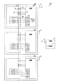
図1に示すように、電池システム100は、3個の電池モジュールM1〜M3と、制御部10と、を備える。各電池モジュールM1〜M3は、セルモジュール20と、監視部30と、を備える。
As shown in FIG. 1, the
セルモジュール20は、複数の電池セル24の直列接続体を有する組電池22を備える。組電池22付近には、組電池22の温度を検出する3個の温度センサTHA1〜THA3が設けられている。各温度センサTHA1〜THA3は、組電池22の相互に異なる箇所の温度を検出し、検出した温度に応じた電圧信号を出力する。なお、温度センサTHA1〜THA3としては、例えば、感温ダイオード、又はサーミスタを用いることができる。本実施形態において、温度センサTHA1〜THA3が「外部部材」に相当する。
The
監視部30は、組電池22を監視する。監視部30は、検出線32を介して組電池22を構成する各電池セル24の両電極に接続されており、各電池セル24の電圧(端子間電圧)を検出し、各電池セル24に応じた電圧信号であるセル電圧データVDを取得する。
The
監視部30にはコネクタ34が設けられている。コネクタ34は、温度センサTHA1〜THA3に接続可能な4個の端子CH1〜CH4を有している。コネクタ34には、温度センサTHA1〜THA3から延びる電気配線36が接続され、これにより監視部30と温度センサTHA1〜THA3とが電気的に接続される。監視部30は、コネクタ34を介して温度センサTHA1〜THA3から入力される電圧信号に基づいて、温度データTDA1〜TDA3を取得する。
The
電気配線36は、コネクタ34の端子CH1〜CH4に対して1対1接続される。本実施形態では、コネクタ34の端子CH1〜CH4の個数が、温度センサTHA1〜THA3の個数よりも1個多い。そのため、コネクタ34では、端子CH1〜CH4のうちいずれか1つが、温度センサTHA1〜THA3に接続されない空き端子となる。コネクタ34の端子CH1〜CH4のうち、いずれの端子を空き端子とするかは、電池モジュールM1〜M3の製造時において作業者により、自由に設定することができる。
The
監視部30は、通信回路38を備えており、取得したセル電圧データVD及び温度データTDA1〜TDA3を制御部10に無線送信する。また、監視部30は、通信回路38を介して制御部10からの各種指令を無線受信する。
The
次に、制御部10について説明する。制御部10は、CPU、ROM、RAM等よりなるマイクロコンピュータを主体として構成され、ROMに記憶された各種の制御プログラムを実行することで各電池モジュールM1〜M3を個別に制御する。
Next, the
制御部10は、各電池モジュールM1〜M3の監視部30と通信可能に構成されている。具体的には、制御部10は、通信回路12を備え、監視部30が無線送信したセル電圧データVD及び温度データTDA1〜TDA3を無線受信する。制御部10は、受信したセル電圧データVD及び温度データTDA1〜TDA3を用いて、組電池22を制御する。例えば、制御部10は、受信したセル電圧データVD及び温度データTDA1〜TDA3を用いて、組電池22の充電状態(SOC:State Of Charge)を演算する。そして、組電池22が過充電や過放電とならないようにするための指令を、通信回路12を介して監視部30に無線送信する。
The
ところで、電池システム100では、電池モジュールM1〜M3毎に充電状態を監視したり、故障診断を実施したりするため、制御部10が電池モジュールM1〜M3を各々識別する必要がある。例えば、各電池モジュールM1〜M3において、監視部30に固有の識別情報IDが設定されている場合を検討する。なお、識別情報IDを設定する形態としては、監視部30が有する記憶部に、識別情報IDが記憶される形態を含む。この場合、制御部10は、監視部30との無線通信により監視部30に設定された識別情報IDを取得することで、各電池モジュールM1〜M3を識別することができる。
By the way, in the
電池システム100では、コスト低減等のために各電池モジュールM1〜M3に含まれる監視部30の共通化が望まれている。しかし、上記の場合、監視部30には電池モジュールM1〜M3毎に異なる識別情報IDが設定されているため、各電池モジュールM1〜M3において、監視部30を共通化することができない問題が生じる。
In the
本実施形態の電池システム100は、上記問題を解決するために、監視部30は、温度センサTHA1〜THA3から入力される電圧信号に基づいて、電池モジュールM1〜M3毎に異なる識別情報IDを生成する。具体的には、電池モジュールM1〜M3毎に、温度センサTHA1〜THA3とコネクタ34の端子CH1〜CH4との接続パターンが異なり、且つ温度センサTHA1〜THA3に接続されない空き端子が異なるように設定されている。そのため、複数の端子CH1〜CH4にそれぞれ入力される信号が、電池モジュールM1〜M3毎に異なる。
In the
監視部30は、複数の端子CH1〜CH4にそれぞれ入力される信号に基づいて、識別情報IDを生成する識別情報生成処理を実施する。監視部30は、温度センサTHA1〜THA3から入力される電圧信号に基づいて識別情報IDを生成することができるため、内部に識別情報IDが設定される必要がない。この結果、電池システム100を構成する複数の電池モジュールM1〜M3において、監視部30を共通化することができる。
The
図2に本実施形態の識別処理及び識別情報生成処理のフローチャートを示す。識別処理は、識別情報生成処理により生成された識別情報IDを用いて各電池モジュールM1〜M3を識別する処理であり、制御部10により実施される。図2(a)は、制御部10による識別処理を示すフローチャートであり、図2(b)は、監視部30による識別情報生成処理を示すフローチャートである。制御部10及び監視部30は、車両の起動時に、つまり車両のイグニッションスイッチをオン状態へ切り替える際に各処理を実施する。
FIG. 2 shows a flowchart of the identification process and the identification information generation process of the present embodiment. The identification process is a process of identifying each battery module M1 to M3 using the identification information ID generated by the identification information generation process, and is performed by the
まず、監視部30による識別情報生成処理について説明する。監視部30は、識別情報生成処理を開始すると、まずステップS30において、制御部10からデータ送信指令を取得したかを判定する。
First, the identification information generation process by the
ステップS30で否定判定すると、ステップS30を繰り返す。一方、ステップS30で肯定判定すると、ステップS32において、セル電圧データVDを取得する。続くステップS34において、温度センサTHA1〜THA3から入力される電圧信号に基づいて、温度データTDA1〜TDA3を取得するための入力処理を実施する。なお、本実施形態において、ステップS34の処理が「入力処理部」に相当する。 If a negative determination is made in step S30, step S30 is repeated. On the other hand, if an affirmative determination is made in step S30, the cell voltage data VD is acquired in step S32. In the following step S34, an input process for acquiring temperature data TDA1 to TDA3 is performed based on the voltage signal input from the temperature sensors THA1 to THA3. In this embodiment, the process of step S34 corresponds to the "input processing unit".
ステップS34では、監視部30は、コネクタ34の複数の端子CH1〜CH4のうち、温度センサTHA1〜THA3に接続される端子に対して、温度センサTHA1〜THA3の電圧信号を所定電圧範囲HV(図4参照)で入力処理する。具体的には、監視部30は、組電池22の温度に応じたアナログ信号である電圧信号を、所定電圧範囲HV内の電圧値を示すデジタル信号である温度データTDA1〜TDA3に変換する。所定電圧範囲HVは、例えば0.5Vから4.5Vの電圧範囲である。
In step S34, the
一方、コネクタ34の複数の端子CH1〜CH4のうち、空き端子には電圧信号が入力さず、空き端子の電圧は、例えば接地電圧などの一定電圧に設定される。監視部30は、空き端子の電圧を、所定電圧範囲HV外の電圧とする。具体的には、監視部30は、空き端子の電圧として、所定電圧範囲HV外の電圧値を示すデジタル信号である範囲外データNDを生成する。範囲外データNDの電圧値は、例えば0Vである。
On the other hand, of the plurality of terminals CH1 to CH4 of the
ステップS36において、識別情報IDを生成する。具体的には、ステップS34で入力処理されたデータを、コネクタ34の端子CH1〜CH4の順番に並べた識別情報IDを生成する。そのため、識別情報IDは、3個の温度データTDA1〜TDA3と1個の範囲外データNDにより構成される。本実施形態では、空き端子が電池モジュールM1〜M3毎に異なるように設定されており、電池モジュールM1〜M3毎に温度データTDA1〜TDA3と範囲外データNDの順番が異なる。そのため、電池モジュールM1〜M3毎に異なる識別情報IDが生成される。なお、本実施形態において、ステップS36の処理が「生成部」に相当する。
In step S36, the identification information ID is generated. Specifically, the identification information ID in which the data input processed in step S34 is arranged in the order of the terminals CH1 to CH4 of the
続くステップS38において、セル電圧データVD及び識別情報IDを含むデータを制御部10に送信し、識別情報生成処理を終了する。
In the following step S38, the data including the cell voltage data VD and the identification information ID is transmitted to the
次に、制御部10による識別処理について説明する。制御部10は、識別処理を開始すると、まずステップS10において、各電池モジュールM1〜M3の監視部30にデータ送信指令を送信する。続くステップS12において、各電池モジュールM1〜M3の監視部30からデータを取得したかを判定する。なお、本実施形態において、ステップS12の処理が「識別情報取得部」に相当する。
Next, the identification process by the
ステップS12で否定判定すると、ステップS12を繰り返す。一方、ステップS12で肯定判定すると、ステップS14において、ステップS12でデータが取得された電池モジュールM1〜M3を識別する。なお、本実施形態において、ステップS14の処理が「識別部」に相当する。 If a negative determination is made in step S12, step S12 is repeated. On the other hand, if an affirmative determination is made in step S12, the battery modules M1 to M3 whose data was acquired in step S12 are identified in step S14. In this embodiment, the process of step S14 corresponds to the "identification unit".
ステップS14では、制御部10は、制御部10の記憶部14(図1参照)に記憶されたマップMP(図3参照)を用いて、ステップS12で取得されたデータに含まれる識別情報IDに基づいて、電池モジュールM1〜M3を識別する。なお、記憶部14は、例えば、ROM、書き換え可能な不揮発性メモリ等によって構成されている。
In step S14, the
マップMPは、電池モジュールM1〜M3と識別情報IDとが対応付けられた対応情報である。マップMPには、電池システム100に含まれる全電池モジュールM1〜M3に対する識別情報IDが、電池モジュールM1〜M3に対応付けて記憶されている。本実施形態では、マップMPに記憶される識別情報IDは、電池システム100に含まれる電池モジュールM1〜M3に対応する識別情報IDに限られる。
The map MP is correspondence information in which the battery modules M1 to M3 and the identification information ID are associated with each other. In the map MP, the identification information IDs for all the battery modules M1 to M3 included in the
続くステップS16において、全電池モジュールM1〜M3の監視部30からデータを取得したかを判定する。ステップS16で否定判定すると、ステップS12に戻る。一方、ステップS16で肯定判定すると、ステップS18において、全電池モジュールM1〜M3が識別されたかを判定する。
In the following step S16, it is determined whether or not the data has been acquired from the
ステップS18で肯定判定すると、識別処理を終了する。一方、ステップS18で否定判定すると、つまり識別されていない非識別モジュールが存在する場合、ステップS20において、非識別モジュールの個数が1個であるかを判定する。なお、非識別モジュールが存在する原因としては、監視部30の不具合により、不正確な識別情報IDが取得されたこととともに、温度センサTHA1〜THA3の不具合により、マップMPに記憶された識別情報IDと異なる識別情報IDが取得されたことが含まれる。
If affirmative determination is made in step S18, the identification process ends. On the other hand, if a negative determination is made in step S18, that is, if there is an unidentified non-identifying module, it is determined in step S20 whether the number of non-identifying modules is one. The reason why the non-identification module exists is that an inaccurate identification information ID is acquired due to a defect in the
ステップS20で否定判定すると、ステップS22において、電池モジュールM1〜M3の識別異常の発生を通知し、識別処理を終了する。ここで、識別異常は、全電池モジュールM1〜M3を識別できない異常である。識別異常が発生した場合、制御部10が各電池モジュールM1〜M3の組電池22の電圧や温度を適切に取得できず、各電池モジュールM1〜M3を適切に制御することができない。そのため、識別異常が発生した場合には、車両は正常に起動されない。なお、識別異常の発生の通知方法としては、警告音を発生させる、又はカーナビゲーション装置のディスプレイに異常を表示させる等の方法がある。
If a negative determination is made in step S20, in step S22, the occurrence of the identification abnormality of the battery modules M1 to M3 is notified, and the identification process ends. Here, the identification abnormality is an abnormality in which all battery modules M1 to M3 cannot be identified. When an identification abnormality occurs, the
一方、ステップS20で肯定すると、ステップS24において、消去法により非識別モジュールを識別する。具体的には、非識別モジュールを、マップMPにおいて電池モジュールM1〜M3の識別に用いられていない識別情報IDに対応付けられた電池モジュールM1〜M3として識別する。 On the other hand, if affirmed in step S20, the non-identifying module is identified by the elimination method in step S24. Specifically, the non-identification module is identified as the battery modules M1 to M3 associated with the identification information ID that is not used to identify the battery modules M1 to M3 in the map MP.
続くステップS26において、交換要求の発生を通知し、識別処理を終了する。ここで、交換要求は、非識別モジュールの交換を促す要求である。交換要求が発生した場合、非識別モジュールが存在するものの、制御部10は全電池モジュールM1〜M3を識別することができ、各電池モジュールM1〜M3の組電池22の電圧や温度を適切に取得できる。そのため、交換要求が発生した場合には、車両は正常に起動される。交換要求の発生を通知することで、ドライバに非識別モジュールの交換を促し、識別異常の発生を抑制することができる。
In the following step S26, the occurrence of the exchange request is notified, and the identification process is terminated. Here, the replacement request is a request for prompting the replacement of the non-identifying module. When a replacement request occurs, although the non-identification module exists, the
続いて、図3に、マップMPを示す。本実施形態では、図1に示すように、電池モジュールM1では、温度センサTHA1がコネクタ34の端子CH1に接続されており、温度センサTHA2が端子CH2に接続されており、温度センサTHA3が端子CH3に接続されている。そのため、図3に示すように、マップMPでは、温度データTDA1、温度データTDA2、温度データTDA3、及び範囲外データNDがこの順に連続する情報が、電池モジュールM1に対応する識別情報IDとして記憶されている。
Subsequently, FIG. 3 shows the map MP. In the present embodiment, as shown in FIG. 1, in the battery module M1, the temperature sensor THA1 is connected to the terminal CH1 of the
同様に、電池モジュールM2では、温度センサTHA1がコネクタ34の端子CH1に接続されており、温度センサTHA2が端子CH2に接続されており、温度センサTHA3が端子CH4に接続されている。そのため、マップMPでは、温度データTDA1、温度データTDA2、範囲外データND、及び温度データTDA3がこの順に連続する情報が、電池モジュールM2に対応する識別情報IDとして記憶されている。
Similarly, in the battery module M2, the temperature sensor THA1 is connected to the terminal CH1 of the
また、電池モジュールM3では、温度センサTHA1がコネクタ34の端子CH1に接続されており、温度センサTHA2が端子CH3に接続されており、温度センサTHA3が端子CH4に接続されている。そのため、マップMPでは、温度データTDA1、範囲外データND、温度データTDA2、及び温度データTDA3がこの順に連続する情報が、電池モジュールM3に対応する識別情報IDとして記憶されている。
Further, in the battery module M3, the temperature sensor THA1 is connected to the terminal CH1 of the
そのため、例えば、制御部10がある監視部30からデータを取得した場合に、そのデータに含まれる識別情報IDが、温度データTDA1、温度データTDA2、温度データTDA3、及び範囲外データNDがこの順に連続する情報であるとする。この場合、制御部10は、そのデータが取得された電池モジュールを電池モジュールM1と識別することができる。
Therefore, for example, when data is acquired from the
具体的には、制御部10は、取得した識別情報IDを、電圧値を示す4個の電圧値データに分割し、各電圧値データが示す電圧値が所定電圧範囲HVに含まれるものであるかを判定する。制御部10は、電圧値データが示す電圧値が所定電圧範囲HVに含まれるものである場合、電圧値データは温度データTDA1〜TDA3であると判定する。また、電圧値データが示す電圧値が所定電圧範囲HVに含まれないものである場合、電圧値データは範囲外データNDであると判定する。電圧値データが温度データTDA1〜TDA3である場合、組電池22の温度によらず、電圧値データが示す電圧値が所定電圧範囲HVに含まれる。そのため、制御部10は、組電池22の温度によらず、電圧値データが温度データTDA1〜TDA3であるかを判定することができる。
Specifically, the
電池モジュールM1の識別後、識別情報IDに含まれる温度データTDA1〜TDA3は、組電池22の温度を取得するために用いられる。つまり、本実施形態では、温度データTDA1〜TDA3は、電池モジュールM1を識別するためのデータと、組電池22の温度を取得するためのデータと、を兼用する。そのため、組電池22の温度を取得するためのデータとは別に、電池モジュールM1を識別するためのデータを生成する必要がない。
After identifying the battery module M1, the temperature data TDA1 to TDA3 included in the identification information ID are used to acquire the temperature of the assembled
図4に、温度データTDA1〜TDA3と範囲外データNDとの温度特性を示す。電池モジュールM1〜M3では、組電池22が動作可能な温度域として所定温度範囲HTが予め定められている。監視部30は、組電池22の温度が所定温度範囲HT内の温度である場合に、温度センサTHA1〜THA3の電圧信号を所定電圧範囲HVで入力処理し、所定電圧範囲HV内の電圧値を示す温度データTDA1〜TDA3を生成する。具体的には、所定温度範囲HTにおける組電池22の温度変化に対応して、所定電圧範囲HVで電圧が線形変化するように入力処理し、詳細には、温度の上昇に対応して電圧が下降する逆特性の温度特性となるように入力処理する。
FIG. 4 shows the temperature characteristics of the temperature data TDA1 to TDA3 and the out-of-range data ND. In the battery modules M1 to M3, a predetermined temperature range HT is predetermined as a temperature range in which the assembled
所定温度範囲HTは、外気温範囲HGと高温範囲HKとを含む。外気温範囲HGは、外気温に対応する温度範囲であり、一般に車両の起動はこの外気温範囲HGにおいて実施される。また、高温範囲HKは、外気温範囲HGよりも高温側の温度範囲である。本実施形態では、識別処理の入力処理において、温度センサTHA1〜THA3の電圧信号が逆特性の温度特性となるように入力処理されるため、所定電圧範囲HVにおいて、外気温範囲HGに対応する電圧が高温範囲HKに対応する電圧よりも高くなる。 The predetermined temperature range HT includes an outside air temperature range HG and a high temperature range HK. The outside air temperature range HG is a temperature range corresponding to the outside air temperature, and the vehicle is generally started in this outside air temperature range HG. Further, the high temperature range HK is a temperature range on the high temperature side of the outside air temperature range HG. In the present embodiment, in the input processing of the identification processing, the voltage signals of the temperature sensors THA1 to THA3 are input processed so as to have the temperature characteristics of the opposite characteristics. Therefore, in the predetermined voltage range HV, the voltage corresponding to the outside air temperature range HG. Is higher than the voltage corresponding to the high temperature range HK.
本実施形態では、この逆特性の温度特性に対応して、空き端子にて生じる所定電圧範囲HV外の電圧を、所定電圧範囲HVよりも低圧側の電圧とし、所定電圧範囲HVよりも低い電圧値を示す範囲外データNDを生成する。そのため、図4に示すように、外気温範囲HGにおいて、温度データTDA1〜TDA3と範囲外データNDとの電圧値差を比較的大きくすることができる。この結果、温度データTDA1〜TDA3と範囲外データNDとの判定が容易となり、識別情報IDを適切に識別することができる。 In the present embodiment, the voltage outside the predetermined voltage range HV generated at the empty terminal is set to the voltage on the lower voltage side than the predetermined voltage range HV in accordance with the temperature characteristic of the reverse characteristic, and the voltage is lower than the predetermined voltage range HV. Generate out-of-range data ND indicating the value. Therefore, as shown in FIG. 4, the voltage value difference between the temperature data TDA1 to TDA3 and the out-of-range data ND can be made relatively large in the outside air temperature range HG. As a result, it becomes easy to determine the temperature data TDA1 to TDA3 and the out-of-range data ND, and the identification information ID can be appropriately identified.
以上詳述した本実施形態によれば、以下の効果が得られるようになる。 According to the present embodiment described in detail above, the following effects can be obtained.
・本実施形態では、各電池モジュールM1〜M3は、監視部30と、監視部30に電気的に接続される温度センサTHA1〜THA3と、を備えており、監視部30は、温度センサTHA1〜THA3から入力される電気信号に基づいて、電池モジュールM1〜M3毎に異なる識別情報IDを生成する。監視部30は、温度センサTHA1〜THA3から入力される電気信号に基づいて識別情報IDを生成することができるため、内部に識別情報IDが設定される必要がない。この結果、電池システム100を構成する複数の電池モジュールM1〜M3において、監視部30を共通化することができる。
In the present embodiment, each battery module M1 to M3 includes a
・本実施形態では、コネクタ34の空き端子が電池モジュールM1〜M3毎に異なるように、温度センサTHA1〜THA3とコネクタ34の端子CH1〜CH4とが接続される。コネクタ34の複数の端子CH1〜CH4のうち、温度センサTHA1〜THA3に接続される端子と空き端子とでは、入力される信号が異なる。そのため、空き端子が電池モジュールM1〜M3毎に異なるように接続されることで、コネクタ34の端子CH1〜CH4にそれぞれ入力される信号を、電池モジュールM1〜M3毎に異ならせることができ、これらの信号に基づいて識別情報IDを生成することができる。
In the present embodiment, the temperature sensors THA1 to THA3 and the terminals CH1 to CH4 of the
・本実施形態では、コネクタ34の複数の端子CH1〜CH4のうち、温度センサTHA1〜THA3に接続される端子に入力される電圧信号は、所定電圧範囲HVで入力処理され、空き端子の電圧は、所定電圧範囲HV外の電圧とされる。そのため、入力処理されたデータから、空き端子を特定することができ、特定した空き端子に関する情報を識別情報IDとして用いて、各電池モジュールM1〜M3を識別することができる。
In the present embodiment, among the plurality of terminals CH1 to CH4 of the
・識別情報IDによる電池モジュールM1〜M3の識別精度を向上させるために、識別情報ID自体が適切に識別されることが望まれる。識別情報IDは、温度データTDA1〜TDA3と範囲外データNDとにより構成されているため、温度データTDA1〜TDA3と範囲外データNDとが適切に判定される必要がある。一般に車両の起動は外気温範囲HGにおいて実施され、識別情報IDは外気温範囲HGにおいて生成される。そのため、外気温範囲HGにおいて、温度データTDA1〜TDA3と範囲外データNDとが適切に判定されることが切望されている。 -In order to improve the identification accuracy of the battery modules M1 to M3 by the identification information ID, it is desired that the identification information ID itself is appropriately identified. Since the identification information ID is composed of the temperature data TDA1 to TDA3 and the out-of-range data ND, it is necessary to appropriately determine the temperature data TDA1 to TDA3 and the out-of-range data ND. Generally, the vehicle is started in the outside air temperature range HG, and the identification information ID is generated in the outside air temperature range HG. Therefore, it is desired that the temperature data TDA1 to TDA3 and the out-of-range data ND are appropriately determined in the outside air temperature range HG.
本実施形態では、外気温範囲HGに対応する電圧と高温範囲HKに対応する電圧との大小関係により、所定電圧範囲HV外の電圧、つまり範囲外データNDが示す電圧値を設定する。例えば、所定電圧範囲HVにおいて、外気温範囲HGに対応する電圧が高温範囲HKに対応する電圧よりも高くなる場合、所定電圧範囲HV外の電圧を所定電圧範囲HVよりも低圧側の電圧とする。これにより、外気温範囲HGにおいて、温度データTDA1〜TDA3と範囲外データNDとが示す電圧値の差を大きくすることができる。この結果、温度データTDA1〜TDA3と範囲外データNDとを適切に判定することができ、識別情報IDによる電池モジュールM1〜M3の識別精度を向上させることができる。 In the present embodiment, the voltage outside the predetermined voltage range HV, that is, the voltage value indicated by the out-of-range data ND is set according to the magnitude relationship between the voltage corresponding to the outside air temperature range HG and the voltage corresponding to the high temperature range HK. For example, in the predetermined voltage range HV, when the voltage corresponding to the outside air temperature range HG is higher than the voltage corresponding to the high temperature range HK, the voltage outside the predetermined voltage range HV is set to the voltage on the lower voltage side than the predetermined voltage range HV. .. Thereby, in the outside air temperature range HG, the difference between the voltage values indicated by the temperature data TDA1 to TDA3 and the out-of-range data ND can be increased. As a result, the temperature data TDA1 to TDA3 and the out-of-range data ND can be appropriately determined, and the identification accuracy of the battery modules M1 to M3 by the identification information ID can be improved.
(第2実施形態)
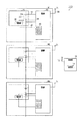
以下、第2実施形態について、第1実施形態との相違点を中心に図5〜7を参照しつつ説明する。図5に示すように、本実施形態では、セルモジュール20が、温度センサTHB1を備える点で第1実施形態と異なる。以下、温度センサTHA1〜THA3を第1センサTHA1〜THA3と呼び、温度センサTHB1を第2センサTHB1と呼ぶ。
(Second Embodiment)
Hereinafter, the second embodiment will be described with reference to FIGS. 5 to 7 focusing on the differences from the first embodiment. As shown in FIG. 5, the
第1センサTHA1〜THA3と第2センサTHB1とでは、組電池22の温度に応じて出力される電圧信号の電圧レベルが異なる。そのため、これらの電圧信号が入力処理された第1センサTHA1〜THA3の第1温度データTDA1〜TDA3と、第2センサTHB1の第2温度データTDB1とでは、組電池22の温度が同じ場合でも、温度データが示す電圧値が異なる。
The voltage level of the voltage signal output differs depending on the temperature of the assembled
図6に、第1温度データTDA1〜TDA3及び第2温度データTDB1の温度特性を示す。図6に示すように、第1温度データTDA1〜TDA3と第2温度データTDB1とは、組電池22の温度に対する出力増減の特性、つまり温度データが示す電圧値の増減特性が同じである。
FIG. 6 shows the temperature characteristics of the first temperature data TDA1 to TDA3 and the second temperature data TDB1. As shown in FIG. 6, the first temperature data TDA1 to TDA3 and the second temperature data TDB1 have the same output increase / decrease characteristics with respect to the temperature of the assembled
一方、第1温度データTDA1〜TDA3が示す電圧値は、第2温度データTDB1が示す電圧値に対して高圧側にオフセットしている。そのため、第2温度データTDB1の電圧範囲である第2電圧範囲HVBは、第1温度データTDA1〜TDA3の電圧範囲である第1電圧範囲HVAに対して、高圧側にオフセットしている。第1電圧範囲HVAは、例えば0.5Vから4.0Vの電圧範囲であり、第2電圧範囲HVBは、例えば1.0Vから4.5Vの電圧範囲であり、オフセットは、例えば0.5Vである。 On the other hand, the voltage values indicated by the first temperature data TDA1 to TDA3 are offset to the high voltage side with respect to the voltage values indicated by the second temperature data TDB1. Therefore, the second voltage range HVB, which is the voltage range of the second temperature data TDB1, is offset to the high voltage side with respect to the first voltage range HVA, which is the voltage range of the first temperature data TDA1 to TDA3. The first voltage range HVA is, for example, a voltage range of 0.5V to 4.0V, the second voltage range HVB is, for example, a voltage range of 1.0V to 4.5V, and the offset is, for example, 0.5V. be.
また、本実施形態では、コネクタ34に空き端子が存在しない点で第1実施形態と異なる。本実施形態では、コネクタ34の端子CH1〜CH4に対する第1センサTHA1〜THA3及び第2センサTHB1の接続パターンが、電池モジュールM1〜M3毎に異なるように接続されており、これにより、第2センサTHB1が接続される端子が電池モジュールM1〜M3毎に異なるように設定されている。
Further, the present embodiment is different from the first embodiment in that there is no empty terminal in the
図7に、本実施形態のマップMPを示す。本実施形態では、図5に示すように、電池モジュールM1では、第1センサTHA1がコネクタ34の端子CH1に接続されており、第1センサTHA2が端子CH2に接続されており、第1センサTHA3が端子CH3に接続されており、第2センサTHB1が端子CH4に接続されている。そのため、図7に示すように、マップMPでは、第1温度データTDA1、第1温度データTDA2、第1温度データTDA3、及び第2温度データTDB1がこの順に連続する情報が、電池モジュールM1に対応する識別情報IDとして記憶されている。
FIG. 7 shows the map MP of this embodiment. In the present embodiment, as shown in FIG. 5, in the battery module M1, the first sensor THA1 is connected to the terminal CH1 of the
同様に、電池モジュールM2では、第1センサTHA1がコネクタ34の端子CH1に接続されており、第1センサTHA2が端子CH2に接続されており、第2センサTHB1が端子CH3に接続されており、第1センサTHA3が端子CH4に接続されている。そのため、マップMPでは、第1温度データTDA1、第1温度データTDA2、第2温度データTDB1、及び第1温度データTDA3がこの順に連続する情報が、電池モジュールM2に対応する識別情報IDとして記憶されている。
Similarly, in the battery module M2, the first sensor THA1 is connected to the terminal CH1 of the
また、電池モジュールM3では、第1センサTHA1がコネクタ34の端子CH1に接続されており、第2センサTHB1が端子CH2に接続されており、第1センサTHA2が端子CH3に接続されており、第1センサTHA3が端子CH4に接続されている。そのため、マップMPでは、第1温度データTDA1、第2温度データTDB1、第1温度データTDA2、及び第1温度データTDA3がこの順に連続する情報が、電池モジュールM3に対応する識別情報IDとして記憶されている。
Further, in the battery module M3, the first sensor THA1 is connected to the terminal CH1 of the
そのため、例えば、制御部10がある監視部30からデータを取得した場合に、そのデータに含まれる識別情報IDが、第1温度データTDA1、第1温度データTDA2、第1温度データTDA3、及び第2温度データTDB1がこの順に連続する情報であるとする。この場合、制御部10は、そのデータが取得された電池モジュールを電池モジュールM1と識別する。
Therefore, for example, when data is acquired from the
具体的には、制御部10は、取得した識別情報IDを、電圧値を示す4個の電圧値データに分割し、4個の電圧値データのうち、最も大きい電圧値を示す電圧値データを選択する。制御部10は、選択された電圧値データを第2温度データTDB1と判定し、その他の電圧値データを第1温度データTDA1〜TDA3と判定する。これにより、第1温度データTDA1〜TDA3と第2温度データTDB1とを判定することができ、これらの温度データTDA1〜TDA3,TDB1から構成される識別情報IDを用いて、各電池モジュールM1〜M3を識別することができる。
Specifically, the
・以上説明した本実施形態によれば、第2センサTHB1が接続される端子が電池モジュールM1〜M3毎に異なるように、温度センサTHA1〜THA3,THB1とコネクタ34の端子CH1〜CH4とが接続される。コネクタ34の複数の端子CH1〜CH4のうち、第1センサTHA1〜THA3に接続される端子と第2センサTHB1に接続される端子とでは、電圧信号の電圧レベルが異なる。そのため、第2センサTHB1が接続される端子を電気モジュール毎に異なるように電気配線36が接続されることで、コネクタ34の端子CH1〜CH4にそれぞれ入力される信号を、電池モジュールM1〜M3毎に異ならせることができ、この信号に基づいて識別情報IDを生成することができる。
-According to the present embodiment described above, the temperature sensors THA1 to THA3 and THB1 are connected to the terminals CH1 to CH4 of the
・本実施形態では、第1温度データTDA1〜TDA3と第2温度データTDB1とは、組電池22の温度に対する出力増減の特性が同じであり、組電池22の温度によらず、第1温度データTDA1〜TDA3と第2温度データTDB1とが示す電圧値の差、つまりオフセットが一定に維持される。この結果、組電池22の温度によらず、一定精度で温度データTDA1〜TDA3と範囲外データNDとを判定することができ、識別情報IDによる電池モジュールM1〜M3の識別精度を向上させることができる。
-In the present embodiment, the first temperature data TDA1 to TDA3 and the second temperature data TDB1 have the same characteristics of output increase / decrease with respect to the temperature of the assembled
(第3実施形態)
以下、第3実施形態について、第1実施形態との相違点を中心に図8を参照しつつ説明する。図8に示すように、本実施形態では、セルモジュール20が、組電池22の電力を用いて監視部30に電力を供給する電源部26を備える点で第1実施形態と異なる。なお、本実施形態において、電源部26が「外部部材」に相当する。
(Third Embodiment)
Hereinafter, the third embodiment will be described with reference to FIG. 8, focusing on the differences from the first embodiment. As shown in FIG. 8, the
監視部30には、電源コネクタ40が設けられている。電源コネクタ40は、電源部26に接続可能な3個の電源端子CH11〜CH13を有している、電源コネクタ40には、電源部26から延びる電源ライン42が接続され、これにより監視部30に電力が供給される。
The
電源ライン42は、電源端子CH11〜CH13のいずれか1個の電源端子に接続される。本実施形態では、電源ライン42が接続される電源端子CH11〜CH13が、電池モジュールM1〜M3毎に異なるように設定されている。そのため、電源ライン42が接続される電源端子CH11〜CH13を識別情報IDとして用いて、各電池モジュールM1〜M3を識別することができる。
The
・以上説明した本実施形態によれば、各電池モジュールM1〜M3は、監視部30と、監視部30に電気的に接続される電源部26と、を備えており、監視部30は、電源部26から供給される電力に基づいて、電池モジュールM1〜M3毎に異なる識別情報IDを生成する。監視部30は、電源部26から供給される電力に基づいて識別情報IDを生成することができるため、内部に識別情報IDが設定される必要がない。この結果、電池システム100を構成する複数の電池モジュールM1〜M3において、監視部30を共通化することができる。
-According to the present embodiment described above, each battery module M1 to M3 includes a
(その他の実施形態)
なお、上記各実施形態は、以下のように変更して実施してもよい。
(Other embodiments)
Each of the above embodiments may be modified as follows.
・電池モジュールの個数は3個に限られず、2個でもよければ、4個以上であってもよい。 -The number of battery modules is not limited to three, and may be two or four or more.
・外部部材は、監視部30に接続される抵抗であってもよい。この抵抗は、電池モジュールM1〜M3の内部において監視部30に接続される内部抵抗であってもよければ、電池モジュールM1〜M3の外部において監視部30に接続される内部抵抗であってもよい。
The external member may be a resistor connected to the
・第1実施形態及び第2実施形態では、温度データTDA1〜TDA3の温度特性が、温度の上昇に対応して電圧が下降する逆特性である例を示したが、これに限られない。温度の上昇に対応して電圧が上昇する正特性であってもよい。 -In the first embodiment and the second embodiment, an example is shown in which the temperature characteristics of the temperature data TDA1 to TDA3 are inverse characteristics in which the voltage decreases in response to the increase in temperature, but the present invention is not limited to this. It may have a positive characteristic that the voltage rises in response to the rise in temperature.
・第1実施形態において、温度データTDA1〜TDA3の温度特性が正特性である場合、所定電圧範囲HVにおいて、外気温範囲HGに対応する電圧が高温範囲HKに対応する電圧よりも低くなる。この場合、この正特性の温度特性に対応して、空き端子にて生じる所定電圧範囲HV外の電圧を、所定電圧範囲HVよりも高圧側の電圧とし、所定電圧範囲HVよりも高い電圧値を示す範囲外データNDを生成する。してもよい。所定電圧範囲HVよりも高い電圧値は、例えば5.0Vである。これにより、外気温範囲HGにおいて、温度データTDA1〜TDA3と範囲外データNDとの電圧値差を比較的大きくすることができる。 -In the first embodiment, when the temperature characteristics of the temperature data TDA1 to TDA3 are positive characteristics, the voltage corresponding to the outside air temperature range HG is lower than the voltage corresponding to the high temperature range HK in the predetermined voltage range HV. In this case, corresponding to the temperature characteristic of the positive characteristic, the voltage outside the predetermined voltage range HV generated at the empty terminal is set to the voltage on the higher voltage side than the predetermined voltage range HV, and the voltage value higher than the predetermined voltage range HV is set. Generate out-of-range data ND as shown. You may. A voltage value higher than the predetermined voltage range HV is, for example, 5.0 V. Thereby, in the outside air temperature range HG, the voltage value difference between the temperature data TDA1 to TDA3 and the out-of-range data ND can be made relatively large.
・第1実施形態において、温度センサの数は3個に限られず、コネクタ34の端子数も4個に限られない。そのため、コネクタ34の空き端子数は1個に限られず、2個以上であってもよい。
-In the first embodiment, the number of temperature sensors is not limited to three, and the number of terminals of the
・第2実施形態において、コネクタ34に空き端子が存在しない例を示したが、例えば第1センサを1個減らすことにより、コネクタ34に空き端子を設けてもよい。この場合、コネクタ34の端子CH1〜CH4に対する第1センサTHA1〜THA2及び第2センサTHB1の接続パターンが、電池モジュールM1〜M3毎に異なるように接続されてもよい。これにより、空き端子と第2センサTHB1が接続される端子との組み合わせが電池モジュールM1〜M3毎に異なるように、各電池モジュールM1〜M3の接続パターンが設定される。空き端子と第2センサTHB1が接続される端子とを組み合わせて用いることで、コネクタ34の端子数を増やすことなく、多くの電池モジュールを識別することができる。
-In the second embodiment, an example in which the
・上記実施形態では、識別処理及び識別情報生成処理が、車両の起動時に実施される例を示したが、これに限られない。車両組付け時に実施されてもよければ、所定の測定周期毎に実施されてもよい。 -In the above embodiment, an example is shown in which the identification process and the identification information generation process are performed when the vehicle is started, but the present invention is not limited to this. It may be carried out at the time of vehicle assembly, or may be carried out at predetermined measurement cycles.
・上記実施形態では、組電池の温度変化に対して、温度データTDA1〜TDA3が示す電圧が線形変形する例を示したが、これに限られない。当該電圧が非線形変形、例えば温度変化に対して指数関数的に変化してもよい。 -In the above embodiment, an example in which the voltage indicated by the temperature data TDA1 to TDA3 is linearly deformed with respect to the temperature change of the assembled battery is shown, but the present invention is not limited to this. The voltage may change exponentially with respect to non-linear deformation, such as temperature changes.
・上記実施形態では、制御部10と監視部30とが通信線により接続されておらず、無線通信により制御部10が監視部30から識別情報ID等を取得する例を示したが、これに限られない。制御部10と監視部30とが通信線により接続されており、有線通信により制御部10が監視部30から識別情報ID等を取得してもよい。例えば、制御部10と複数の監視部30とが、通信線により環状に接続されている場合、監視部30の接続の順序に基づいて識別情報IDを生成することができるが、それに代えて外部部材から入力される電気信号に基づいて識別情報IDを生成してもよい。
-In the above embodiment, the
22…組電池、24…電池セル、26…電源部、30…監視部、100…電池システム、ID…識別情報、M1〜M3…電池モジュール、THA1〜THA3…(第1)温度センサ、THB1…第2温度センサ。 22 ... assembled battery, 24 ... battery cell, 26 ... power supply unit, 30 ... monitoring unit, 100 ... battery system, ID ... identification information, M1 to M3 ... battery module, THA1 to THA3 ... (first) temperature sensor, THB1 ... Second temperature sensor.
Claims (4)
各前記電池モジュールは、
複数の電池セル(24)の直列接続体を有する組電池(22)と、
前記組電池を監視する監視部(30)と、
前記監視部に電気的に接続された外部部材(THA1〜THA3,THB1,26)と、を備え、
前記監視部は、
前記外部部材から入力される電気信号に基づいて、前記電池モジュール毎に異なる識別情報(ID)を生成する生成部と、
複数の端子(CH1〜CH4)を有して構成され、前記外部部材から延びる電気配線(36)が接続されるコネクタ(34)と、を有し、
前記電気配線は、前記コネクタに対して、前記複数の端子のうち少なくともいずれか1つを空き端子とし、且つ前記空き端子が前記電池モジュール毎に異なるように接続されており、
前記生成部は、前記複数の端子にそれぞれ入力される信号に基づいて、前記識別情報を生成し、
前記外部部材は、前記組電池の温度に応じた電圧信号を出力する温度センサ(THA1〜THA3)であり、
前記監視部は、さらに前記温度センサの電圧信号を所定電圧範囲(HV)で入力処理する一方、前記空き端子の電圧を、前記所定電圧範囲外の電圧とする入力処理部を有する電池システム。 A battery system (100) including a plurality of battery modules (M1 to M3).
Each of the battery modules
An assembled battery (22) having a series connection of a plurality of battery cells (24),
A monitoring unit (30) that monitors the assembled battery and
An external member (THA1 to THA3, THB1, 26) electrically connected to the monitoring unit is provided.
The monitoring unit
A generation unit that generates different identification information (ID) for each battery module based on an electric signal input from the external member .
It has a connector (34) which is configured to have a plurality of terminals (CH1 to CH4) and to which an electric wiring (36) extending from the external member is connected.
In the electrical wiring, at least one of the plurality of terminals is an empty terminal, and the empty terminal is connected to the connector so as to be different for each battery module.
The generation unit generates the identification information based on the signals input to the plurality of terminals, respectively.
The external member is a temperature sensor (THA1 to THA3) that outputs a voltage signal according to the temperature of the assembled battery.
The monitoring unit further inputs and processes the voltage signal of the temperature sensor in a predetermined voltage range (HV), while the battery system has an input processing unit that sets the voltage of the empty terminal to a voltage outside the predetermined voltage range.
各前記電池モジュールは、Each of the battery modules
複数の電池セル(24)の直列接続体を有する組電池(22)と、An assembled battery (22) having a series connection of a plurality of battery cells (24),
前記組電池を監視する監視部(30)と、A monitoring unit (30) that monitors the assembled battery and
前記監視部に電気的に接続された外部部材(THA1〜THA3,THB1,26)と、を備え、An external member (THA1 to THA3, THB1, 26) electrically connected to the monitoring unit is provided.
前記監視部は、The monitoring unit
前記外部部材から入力される電気信号に基づいて、前記電池モジュール毎に異なる識別情報(ID)を生成する生成部と、A generation unit that generates different identification information (ID) for each battery module based on an electric signal input from the external member.
複数の端子(CH1〜CH4)を有して構成され、前記外部部材からの延びる電気配線(36)が接続されるコネクタ(34)と、を有し、It has a connector (34) which is configured to have a plurality of terminals (CH1 to CH4) and to which an electric wiring (36) extending from the external member is connected.
前記外部部材は、前記組電池の温度に応じた電圧信号を出力する温度センサ(THA1〜THA3,THB1)であり、The external member is a temperature sensor (THA1 to THA3, THB1) that outputs a voltage signal according to the temperature of the assembled battery.
前記温度センサは、前記複数の端子のそれぞれに接続されるセンサとして、温度に対する電圧レベルが異なる第1センサ(THA1〜THA3)及び第2センサ(THB1)を含み、前記複数の端子に対する前記第1センサ及び前記第2センサの接続パターンが前記電池モジュール毎に異なるように接続されており、The temperature sensor includes a first sensor (THA1 to THA3) and a second sensor (THB1) having different voltage levels with respect to temperature as sensors connected to each of the plurality of terminals, and the first sensor for the plurality of terminals. The connection pattern of the sensor and the second sensor is connected so as to be different for each battery module.
前記生成部は、前記複数の端子にそれぞれ入力される信号に基づいて、前記識別情報を生成する電池システム。The generation unit is a battery system that generates the identification information based on signals input to the plurality of terminals.
前記制御部は、
前記電池モジュールと前記識別情報とが対応付けられたマップ(MP)が記憶される記憶部(14)と、
各前記電池モジュールの前記監視部から前記識別情報を取得する識別情報取得部と、
前記マップを用いて、前記識別情報取得部により取得された前記識別情報に基づいて、前記識別情報が取得された前記電池モジュールを識別する識別部と、を備える請求項1から請求項3までのいずれか一項に記載の電池システム。 The battery system includes a control unit (10) capable of communicating with the monitoring unit of each battery module.
The control unit
A storage unit (14) that stores a map (MP) in which the battery module and the identification information are associated with each other.
An identification information acquisition unit that acquires the identification information from the monitoring unit of each battery module,
Claims 1 to 3 include an identification unit that identifies the battery module from which the identification information has been acquired based on the identification information acquired by the identification information acquisition unit using the map. The battery system according to any one item.
Priority Applications (6)
| Application Number | Priority Date | Filing Date | Title |
|---|---|---|---|
| JP2018227544A JP6935793B2 (en) | 2018-12-04 | 2018-12-04 | Battery system |
| PCT/JP2019/046587 WO2020116312A1 (en) | 2018-12-04 | 2019-11-28 | Battery system |
| US17/339,265 US11876193B2 (en) | 2018-12-04 | 2021-06-04 | Battery system |
| JP2021137399A JP7251580B2 (en) | 2018-12-04 | 2021-08-25 | battery system |
| JP2023044813A JP2023080115A (en) | 2018-12-04 | 2023-03-21 | battery system |
| US18/521,300 US20240097219A1 (en) | 2018-12-04 | 2023-11-28 | Battery system |
Applications Claiming Priority (1)
| Application Number | Priority Date | Filing Date | Title |
|---|---|---|---|
| JP2018227544A JP6935793B2 (en) | 2018-12-04 | 2018-12-04 | Battery system |
Related Child Applications (1)
| Application Number | Title | Priority Date | Filing Date |
|---|---|---|---|
| JP2021137399A Division JP7251580B2 (en) | 2018-12-04 | 2021-08-25 | battery system |
Publications (3)
| Publication Number | Publication Date |
|---|---|
| JP2020091978A JP2020091978A (en) | 2020-06-11 |
| JP2020091978A5 JP2020091978A5 (en) | 2020-12-10 |
| JP6935793B2 true JP6935793B2 (en) | 2021-09-15 |
Family
ID=70974196
Family Applications (3)
| Application Number | Title | Priority Date | Filing Date |
|---|---|---|---|
| JP2018227544A Active JP6935793B2 (en) | 2018-12-04 | 2018-12-04 | Battery system |
| JP2021137399A Active JP7251580B2 (en) | 2018-12-04 | 2021-08-25 | battery system |
| JP2023044813A Pending JP2023080115A (en) | 2018-12-04 | 2023-03-21 | battery system |
Family Applications After (2)
| Application Number | Title | Priority Date | Filing Date |
|---|---|---|---|
| JP2021137399A Active JP7251580B2 (en) | 2018-12-04 | 2021-08-25 | battery system |
| JP2023044813A Pending JP2023080115A (en) | 2018-12-04 | 2023-03-21 | battery system |
Country Status (3)
| Country | Link |
|---|---|
| US (2) | US11876193B2 (en) |
| JP (3) | JP6935793B2 (en) |
| WO (1) | WO2020116312A1 (en) |
Families Citing this family (10)
| Publication number | Priority date | Publication date | Assignee | Title |
|---|---|---|---|---|
| FR2650156A1 (en) | 1989-07-26 | 1991-02-01 | Bizet Andre | THANATOPRAXIC LIQUID |
| JP7099339B2 (en) * | 2019-01-18 | 2022-07-12 | 株式会社デンソー | Battery system |
| CN115023365A (en) | 2020-01-23 | 2022-09-06 | 松下知识产权经营株式会社 | Authentication method for power storage group, charging device, electric moving body, and control device for electric moving body |
| CN113270649B (en) * | 2020-02-17 | 2024-01-30 | 丰田自动车株式会社 | Battery control device, battery control method, storage medium, and vehicle |
| CN114597985A (en) | 2020-12-03 | 2022-06-07 | 麦太保有限公司 | Storage battery pack, storage battery driven apparatus, external charger, and configuration method |
| WO2023028844A1 (en) | 2021-08-31 | 2023-03-09 | 宁德时代新能源科技股份有限公司 | Vehicle battery swapping method, battery swapping station, vehicle, and system |
| CN116461376A (en) | 2022-01-07 | 2023-07-21 | 宁德时代新能源科技股份有限公司 | Battery replacement verification method and device, electronic equipment, battery replacement station and vehicle |
| US20230280402A1 (en) | 2022-03-07 | 2023-09-07 | Mediatek Inc. | Universal gauge master solution at multi-battery system |
| KR20230134338A (en) | 2022-03-14 | 2023-09-21 | 에스케이온 주식회사 | End plate assembly including thermistor, battery module and battery pack including the same |
| JP2024041503A (en) | 2022-09-14 | 2024-03-27 | カワサキモータース株式会社 | Battery management method, storage control device, movable body and server |
Family Cites Families (9)
| Publication number | Priority date | Publication date | Assignee | Title |
|---|---|---|---|---|
| JP2006172303A (en) | 2004-12-17 | 2006-06-29 | Ricoh Co Ltd | Reader and/or writer for id tag |
| EP2183835A2 (en) * | 2007-03-26 | 2010-05-12 | The Gillette Company | Ultra fast battery charger with battery sensing |
| US9762069B2 (en) * | 2009-05-19 | 2017-09-12 | Duracell U.S. Operations, Inc. | Multi-use fast rate charging stand |
| US8341449B2 (en) | 2010-04-16 | 2012-12-25 | Lg Chem, Ltd. | Battery management system and method for transferring data within the battery management system |
| US9696383B2 (en) | 2011-10-07 | 2017-07-04 | Hitachi Automotive Systems, Ltd. | Battery monitoring system, host controller, and battery monitoring device |
| US10063072B2 (en) * | 2013-11-29 | 2018-08-28 | Hitachi Automotive Systems, Ltd. | Battery module and assembled battery |
| JP6524274B2 (en) * | 2017-05-26 | 2019-06-05 | ローム株式会社 | Traffic light monitor |
| JP7036605B2 (en) * | 2018-01-30 | 2022-03-15 | プライムアースEvエナジー株式会社 | Battery state estimation device and battery state estimation method |
| DE112019002799T5 (en) * | 2018-06-01 | 2021-03-18 | Sumitomo Electric Industries, Ltd. | Battery management device, battery information processing system, and battery information processing method |
-
2018
- 2018-12-04 JP JP2018227544A patent/JP6935793B2/en active Active
-
2019
- 2019-11-28 WO PCT/JP2019/046587 patent/WO2020116312A1/en active Application Filing
-
2021
- 2021-06-04 US US17/339,265 patent/US11876193B2/en active Active
- 2021-08-25 JP JP2021137399A patent/JP7251580B2/en active Active
-
2023
- 2023-03-21 JP JP2023044813A patent/JP2023080115A/en active Pending
- 2023-11-28 US US18/521,300 patent/US20240097219A1/en active Pending
Also Published As
| Publication number | Publication date |
|---|---|
| JP2023080115A (en) | 2023-06-08 |
| JP7251580B2 (en) | 2023-04-04 |
| US20210296714A1 (en) | 2021-09-23 |
| JP2020091978A (en) | 2020-06-11 |
| US20240097219A1 (en) | 2024-03-21 |
| JP2021185580A (en) | 2021-12-09 |
| US11876193B2 (en) | 2024-01-16 |
| WO2020116312A1 (en) | 2020-06-11 |
Similar Documents
| Publication | Publication Date | Title |
|---|---|---|
| JP6935793B2 (en) | Battery system | |
| JP6381987B2 (en) | Charge control device, battery pack and charger | |
| EP2559135B1 (en) | Battery management system and method for transferring data within the battery management system | |
| JP6819233B2 (en) | Battery monitoring system for vehicles | |
| JP7028146B2 (en) | Battery system | |
| US11005274B2 (en) | Sensing apparatus and battery management system including the same | |
| JP7416133B2 (en) | Battery system, monitoring device and monitoring section | |
| JP2011067047A (en) | Battery system | |
| KR20210031172A (en) | Method for diagnosing status of battery, the electronic device and storage medium therefor | |
| US20180375371A1 (en) | Battery Monitoring and Control System | |
| KR20120124432A (en) | Device and method for determining a range of a battery characteristic curve | |
| KR20190101582A (en) | Apparatus and method for controlling a charage and discharge of battery | |
| KR102500690B1 (en) | Battery status based charging control method and appratus thereof | |
| JP2019176633A (en) | Electronic apparatus, method for determining battery service life, and battery service life determining program | |
| JP2011127947A (en) | Failure diagnostic device | |
| JP6390682B2 (en) | Charging system | |
| US7359818B2 (en) | Sensor apparatus, control system having the same and offset correction method | |
| US20190260092A1 (en) | Determination method of smoke emission in battery, and battery system | |
| JP2023077075A (en) | Battery monitoring system, battery monitoring device, and battery monitoring method | |
| JP5791584B2 (en) | Voltage monitoring system, voltage monitoring apparatus, and voltage monitoring method | |
| JP6880988B2 (en) | Battery monitoring integrated circuit device | |
| US8222859B2 (en) | Method for determining the charge state of a motor vehicle battery when the drive unit is switched off | |
| KR102042754B1 (en) | Apparatus of Measuring Voltage of Battery Pack and Method thereof | |
| JP2012095388A (en) | Battery state monitor | |
| JPWO2019012611A1 (en) | Processing unit |
Legal Events
| Date | Code | Title | Description |
|---|---|---|---|
| A521 | Request for written amendment filed |
Free format text: JAPANESE INTERMEDIATE CODE: A523 Effective date: 20201028 |
|
| A621 | Written request for application examination |
Free format text: JAPANESE INTERMEDIATE CODE: A621 Effective date: 20201028 |
|
| TRDD | Decision of grant or rejection written | ||
| A01 | Written decision to grant a patent or to grant a registration (utility model) |
Free format text: JAPANESE INTERMEDIATE CODE: A01 Effective date: 20210727 |
|
| A61 | First payment of annual fees (during grant procedure) |
Free format text: JAPANESE INTERMEDIATE CODE: A61 Effective date: 20210809 |
|
| R151 | Written notification of patent or utility model registration |
Ref document number: 6935793 Country of ref document: JP Free format text: JAPANESE INTERMEDIATE CODE: R151 |
|
| R250 | Receipt of annual fees |
Free format text: JAPANESE INTERMEDIATE CODE: R250 |