JP6931647B2 - Reactive armor - Google Patents
Reactive armor Download PDFInfo
- Publication number
- JP6931647B2 JP6931647B2 JP2018521100A JP2018521100A JP6931647B2 JP 6931647 B2 JP6931647 B2 JP 6931647B2 JP 2018521100 A JP2018521100 A JP 2018521100A JP 2018521100 A JP2018521100 A JP 2018521100A JP 6931647 B2 JP6931647 B2 JP 6931647B2
- Authority
- JP
- Japan
- Prior art keywords
- explosive
- layer
- reactive armor
- module
- armor module
- Prior art date
- Legal status (The legal status is an assumption and is not a legal conclusion. Google has not performed a legal analysis and makes no representation as to the accuracy of the status listed.)
- Active
Links
Images


Classifications
-
- F—MECHANICAL ENGINEERING; LIGHTING; HEATING; WEAPONS; BLASTING
- F41—WEAPONS
- F41H—ARMOUR; ARMOURED TURRETS; ARMOURED OR ARMED VEHICLES; MEANS OF ATTACK OR DEFENCE, e.g. CAMOUFLAGE, IN GENERAL
- F41H5/00—Armour; Armour plates
- F41H5/007—Reactive armour; Dynamic armour
-
- F—MECHANICAL ENGINEERING; LIGHTING; HEATING; WEAPONS; BLASTING
- F41—WEAPONS
- F41H—ARMOUR; ARMOURED TURRETS; ARMOURED OR ARMED VEHICLES; MEANS OF ATTACK OR DEFENCE, e.g. CAMOUFLAGE, IN GENERAL
- F41H5/00—Armour; Armour plates
- F41H5/02—Plate construction
- F41H5/04—Plate construction composed of more than one layer
-
- F—MECHANICAL ENGINEERING; LIGHTING; HEATING; WEAPONS; BLASTING
- F41—WEAPONS
- F41H—ARMOUR; ARMOURED TURRETS; ARMOURED OR ARMED VEHICLES; MEANS OF ATTACK OR DEFENCE, e.g. CAMOUFLAGE, IN GENERAL
- F41H7/00—Armoured or armed vehicles
- F41H7/02—Land vehicles with enclosing armour, e.g. tanks
- F41H7/04—Armour construction
Description
本発明は、概して、飛来する運動エネルギー貫通弾(KEP:Kinetic Energy Penetrator)または高エネルギー対戦車(HEAT:High Energy Anti−Tank)弾頭から装甲車両または装甲構造体を保護する技術分野に関する。より具体的には、本発明は、飛来するタンデム弾頭から装甲車両または装甲構造体を保護する技術に関する。 The present invention relates generally to flying to kinetic energy PierceS (KEP: Kinetic Energy Penetrator) or high energy anti-tank: from (HEAT High Energy Anti-Tank) warhead technical field of protecting armored vehicles or armored structure. More specifically, the present invention relates to techniques for protecting an armored vehicle or armored structure from incoming tandem warheads.
本来、HEAT弾は、装甲車両の外装を貫通することによって作動し、内部の乗員の殺傷、重要な機械システムの機能停止、あるいはその両方に作用する。 Originally, HEAT ammunition operates by penetrating the exterior of an armored vehicle, killing internal occupants, shutting down critical mechanical systems, or both.
装甲車両が成形炸薬搭載HEATの衝撃に耐えられるようにするために、爆発反応性装甲(ERA:Explosive Reactive Armor)と名付けられた外装爆発要素が車両の装甲に取り付けられている。 To allow the armored vehicle to withstand the impact of a high-explosive-molded HEAT, an exterior explosive element named Explosive Reactive Armor (ERA) is attached to the vehicle's armor.
標準的なERAは、反応性要素または動的要素と呼ばれる、通常は金属製の2枚の板に挟まれた、高爆発性のシートまたは圧延鋼板からできている。 A standard ERA is made of a highly explosive sheet or rolled steel sheet, usually sandwiched between two metal plates, called reactive or dynamic elements.
一例では、飛来するロケット推進式HEAT、例えばRPG−7(Ruchnoy Protivotankovyy Granatomyot 7)、を衝突時に無力化するために、前記反応性装甲の前記高性能爆薬が爆発して、前記反応性装甲の金属板を、成形炸薬のジェット(高速噴流)に向けて強制的に発射する。発射された板は、金属製のジェット貫通弾を崩壊させる。 In one example, in order to neutralize a flying rocket-propelled HEAT, such as an RPG-7 (Ruchnoy Protivotankovyy Granatomyot 7) , in the event of a collision, the high-performance explosive in the reactive armor explodes and the metal in the reactive armor. The plate is forcibly fired at a jet of shaped charge (high-speed jet). The fired board destroys a metal jet penetrating bullet.
従来技術の一例では、前記ERAの顕著な有効性は、主に二つの基本的なメカニズムに起因する。第1に、前記移動中の板は、成形炸薬のジェットの衝突時の有効速度及び角度を変化させる。その結果、前記ジェットの入射角を変化させ、これによって、前記ジェットの集中度を低下させる。第2には、前記板は、成形炸薬の弾頭のどの衝突方向に対しても角度がついており、また、前記板は通常外向きに移動しているので、前記板の上での衝突点は時間とともに変化し、前記ジェットは前記板の新しい別の部分を切断しながら進行する必要がある。この第2の効果によって、衝突中の有効板厚を大きく増加させる。 In one example of the prior art, the remarkable effectiveness of the ERA is primarily due to two basic mechanisms. First, the moving plate changes the effective velocity and angle of the shaped charge jet at the time of collision. As a result, the angle of incidence of the jet is changed, thereby reducing the concentration of the jet. Second, the plate is angled with respect to any direction of impact of the shaped charge warhead, and since the plate normally moves outward, the collision point on the plate is As it changes over time, the jet needs to travel while cutting another new portion of the plate. This second effect greatly increases the effective plate thickness during collision.
また、前記ERAは、RPG−7、TOW(Tube‐launched, Optically‐tracked, Wire‐guided)、LAW(Light Anti-Tank Weapon)等の一段型ロケット推進式HEAT成形弾頭の迎撃に非常に有効であることが証明されている。 In addition, the ERA is very effective in intercepting single-stage rocket-propelled HEAT-formed warheads such as RPG-7, TOW (Tube-launched, Optically-tracked, Wire-guided), and LAW (Light Anti-Tank Weapon). It has been proven to be.
また、兵士が、装甲車の迎撃にロケット推進式HEATを使用することが多く、前記ERAの迎撃にタンデム爆弾という名前の新しい弾頭技術が開発されている。本質的に、タンデム爆弾兵器は、2段階以上の爆発段階を有する爆発装置または飛翔体である。このタンデム爆弾兵器は、装甲車(主に戦車)を対戦車爆弾から守るために設計された反応性装甲に対して効果的である。 Also, soldiers often use rocket-propelled HEATs to intercept armored vehicles, and a new warhead technology named tandem bombs has been developed to intercept the ERA. In essence, a tandem bomb weapon is an explosive device or projectile with two or more stages of explosion. This tandem bomb weapon is effective against reactive armor designed to protect armored vehicles (mainly tanks) from anti-tank bombs.
前記タンデム爆弾は、2つ以上の爆発段階を持つ。前記タンデム爆弾兵器の第1の爆発段階は、典型的には、第2の弾頭が妨害無しに通過するようにするため、衝突時に前記ERAをトリガする程度の威力の弱い炸薬である。一般に、これは主炸薬が飛来する前に前記反応性装甲を爆発させ、迎撃用爆発のタイミングが第2の爆発段階に飛来する主炸薬を破壊しないようにすることを意図している。前記タンデム爆弾の第2の爆発段階は、第1の爆発位置と同じ場所を標的とする。これは、反応性装甲の盲点である。前記反応性装甲は、HEATジェットの衝撃に耐えるための装甲車両の主要な武器であるので、前記反応性装甲が第1の爆発段階で無効化されると、主炸薬(第2の爆発用)は前記車両の主装甲を貫通する可能性が増大する。 The tandem bomb has two or more explosion stages. The first detonation stage of the tandem bomb weapon is typically a weak explosive that triggers the ERA in the event of a collision so that the second warhead can pass unimpeded. In general, this is intended to detonate the reactive armor before the main explosive arrives so that the timing of the interception explosion does not destroy the main explosive that arrives in the second explosion stage. The second explosion stage of the tandem bomb targets the same location as the first explosion location. This is the blind spot of reactive armor. Since the reactive armor is the main weapon of the armored vehicle to withstand the impact of the HEAT jet, when the reactive armor is disabled in the first explosion stage, the main explosive charge (for the second explosion). Increases the likelihood of penetrating the main armor of the vehicle.
したがって、本発明の目的は、タンデム弾頭を迎撃することができる反応性装甲モジュールを提供することである。 Therefore, it is an object of the present invention to provide a reactive armor module capable of intercepting tandem warheads.
本発明の別の目的は、タンデム弾頭の攻撃に耐えることができるように既存の反応性装甲モジュールの感度を改良し増強することである。 Another object of the present invention is to improve and enhance the sensitivity of existing reactive armor modules so that they can withstand the attack of tandem warheads.
本発明のさらに別の目的は、前記改良した反応性装甲を、容易で、比較的軽量で、かつ信頼性の高い形で提供することである。 Yet another object of the present invention is to provide the improved reactive armor in an easy, relatively lightweight and reliable form.
本発明の第1の態様によれば、本発明が提供する反応性装甲は、第1トリガ・スクリーンと爆薬層とを含む爆発反応性装甲モジュールと、前記反応性装甲モジュールの近傍に配置され、起爆のために前記第1トリガ・スクリーンに接続された、少なくとも1つの爆発モジュールとを含む。 According to the first aspect of the present invention, the reactive armor provided by the present invention is arranged in the vicinity of the explosive reactive armor module including the first trigger screen and the explosive layer and the reactive armor module. Includes at least one explosion module connected to the first trigger screen for detonation.
本発明の第2の態様によれば、本発明が提供する反応性装甲モジュールは、飛来する飛翔体によってトリガ可能な爆薬層を有し、前記爆薬層は、前記飛来する飛翔体に対して爆破した剪断部品を発射するように成形される。 According to a second aspect of the invention, the reactive armor module provided by the present invention has an explosive layer that can be triggered by an incoming projectile, the explosive layer exploding against the flying projectile. It is molded to fire the sheared parts.
本発明の第3の態様によれば、本発明が提供する反応性装甲モジュールは、第1先端部及び第2先端部と、前記第1先端部と前記第2先端部との間に延在し、かつ、それぞれの爆薬層と整列する第1鋼鉄層及び第2鋼鉄層と、前記第1鋼鉄層に隣接する前記第1先端部に位置する第1炸薬と、前記第2鋼鉄層に隣接する前記第2先端部に位置する第2炸薬と、飛来する飛翔体に反応してはさみ爆発の効果を出すために、前記第1炸薬および前記第2炸薬を時間遅延させて爆発させるように構成されたトリガ・スクリーンとを含む。 According to a third aspect of the present invention, the reactive armor module provided by the present invention extends between the first tip and the second tip and between the first tip and the second tip. The first steel layer and the second steel layer aligned with the respective explosive layers, the first explosive located at the first tip adjacent to the first steel layer, and adjacent to the second steel layer. The first explosive and the second explosive are configured to explode with a time delay in order to produce the effect of scissors explosion in response to the second explosive located at the second tip and the flying projectile. Includes a triggered screen.
また、様々な態様において、前記反応性装甲モジュールは、剛性粒子から成る粒子層を少なくとも1層、含むことができ、前記剛性粒子は、複数の爆薬層に関係付けて配置され、前記爆薬層の爆発の後に、飛来するジェットを崩壊させるための粒子雲を形成する。前記反応性装甲モジュールにおいて、前記粒子層内の前記剛性粒子の少なくともいくつかは、比較的剛性の低い外殻によって囲まれた剛性コアを含むことができる。前記モジュールにおいて、前記爆薬層の少なくとも1つは、爆薬レンズを有する成形炸薬を含むことができる。 Also, in various embodiments, the reactive armor module may include at least one particle layer made of rigid particles, the rigid particles being arranged in relation to a plurality of explosive layers and of the explosive layer. After the explosion, it forms a particle cloud to collapse the incoming jet. In the reactive armor module, at least some of the rigid particles in the particle layer can include a rigid core surrounded by a relatively less rigid outer shell. In the module, at least one of the explosive layers can include a shaped charge with an explosive lens.
前記爆薬層は、前記モジュール全体に亘って不均一に分散することによって分裂的な波面を形成することができる。 The explosive layer can form a split wave surface by unevenly dispersing over the entire module.
前記爆薬層の1つは、空孔または溝を少なくとも1つ含む成形領域を少なくとも1つ含むことができる。 One of the explosive layers can include at least one molding region containing at least one pore or groove.
前記反応性装甲モジュールは、剛性粒子から成る粒子層を少なくとも1層含むことができ、前記剛性粒子は、複数の爆薬層に関係付けて配置され、前記爆薬層の爆発の後に、飛来するジェットを崩壊させるための粒子雲を形成する。 The reactive armor module may include at least one particle layer of rigid particles, which are arranged in relation to a plurality of explosive layers to allow jets to fly after the explosion of the explosive layers. Form a particle cloud to collapse.
前記粒子層中の前記剛性粒子の少なくともいくつかは、比較的剛性の低い外殻によって取り囲まれた剛性コアを含むことができる。 At least some of the rigid particles in the particle layer can include a rigid core surrounded by a relatively less rigid outer shell.
前記爆薬層の少なくとも1つは、成形炸薬を含むことができる。 At least one of the explosive layers can include a shaped charge.
前記爆薬層の少なくとも1つは、少なくとも1つの爆薬レンズを含むことができる。 At least one of the explosive layers can include at least one explosive lens.
前記爆薬層の少なくとも1つは、前記モジュール全体に亘って不均一に分散することによって分裂的な波面を形成することができる。 At least one of the explosive layers can form a split wave front by being unevenly dispersed throughout the module.
前記爆薬層の少なくとも1つは、空孔または溝を少なくとも1つ含む、成形領域を少なくとも1つ含む。 At least one of the explosive layers comprises at least one molding region containing at least one pore or groove.
前記モジュールは、複数の爆薬レンズに成形された少なくとも一つの爆薬層を含むことができ、前記レンズは、飛来する飛翔体に剪断力を加えるようにトリガすることができる。 The module can include at least one explosive layer formed into a plurality of explosive lenses, which can be triggered to exert a shearing force on the incoming projectile.
前記モジュールは、前記爆薬層を一層、または複数層トリガするためのトリガ・スクリーンを含むことができる。 The module may include a trigger screen for triggering the explosive layer in one or more layers.
前記スクリーンは、少なくとも2つのトリガ部に分割することができ、各トリガ部は、飛来する飛翔体の異なる接近角度によってトリガされ、前記爆薬層の異なる部分で爆発を起こすことができる。 The screen can be divided into at least two trigger sections, each of which can be triggered by a different approach angle of the incoming projectile, causing an explosion at different parts of the explosive layer.
前記爆薬層の爆発の後に、飛来するジェットを崩壊させるための粒子雲を形成するように、前記複数の爆薬層に対して剛性粒子の層を少なくとも1層配置することができる。 After the explosion of the explosive layer, at least one layer of rigid particles can be arranged with respect to the plurality of explosive layers so as to form a particle cloud for collapsing the incoming jet.
前記粒子層内の前記剛性粒子の少なくともいくつかは、比較的剛性の低い外殻によって囲まれた剛性コアを含むことができる。 At least some of the rigid particles in the particle layer can include a rigid core surrounded by a relatively less rigid outer shell.
前記爆薬層の少なくとも1つは成形炸薬を含むことができる。 At least one of the explosive layers can contain a shaped charge.
前記爆薬層の少なくとも1つは、少なくとも1つの爆薬レンズを含むことができる。 At least one of the explosive layers can include at least one explosive lens.
前記爆薬層の少なくとも1つは、前記モジュール全体に不均一に分散され、それにより分列的な波面を形成することができる。 At least one of the explosive layers can be unevenly dispersed throughout the module, thereby forming a segmented wave front.
前記爆薬層の少なくとも1つは、少なくとも1つの空孔または少なくとも1つの溝を含む少なくとも1つの成形領域を含むことができる。 At least one of the explosive layers can include at least one molding region containing at least one pore or at least one groove.
一実施形態では、複数の爆薬レンズに成形された爆薬層を少なくとも1層含むことができ、複数の前記爆薬レンズは、飛来する飛翔体に対して剪断力を与えるようにトリガすることができる。 In one embodiment, at least one explosive layer formed into a plurality of explosive lenses can be included, and the plurality of explosive lenses can be triggered to exert a shearing force on an incoming projectile.
前記モジュールは、複数の爆薬レンズに成形された爆薬層を少なくとも1層含むことができ、複数の前記爆薬レンズは、飛来する飛翔体に対して剪断力を与えるようにトリガすることができる。 The module can include at least one explosive layer formed into a plurality of explosive lenses, and the plurality of explosive lenses can be triggered to exert a shearing force on an incoming projectile.
前記モジュールは、前記爆薬層を一層、または複数層の爆薬層をトリガするためのトリガ・スクリーンを含むことができる。 The module may include a trigger screen for triggering the explosive layer with one or more layers of explosives.
前記スクリーンは、少なくとも2つのトリガ部に分割することができ、各トリガ部は、飛来する飛翔体の異なる接近角度によってトリガされ、前記爆薬層の異なる部分で爆発を起こすことができる。 The screen can be divided into at least two trigger sections, each of which can be triggered by a different approach angle of the incoming projectile, causing an explosion at different parts of the explosive layer.
前記モジュールは、時間をあけて順番にまたは同時に、異なる爆薬層またはそれぞれの爆薬層の異なる部分を爆発させることができる。 The module can explode different explosive layers or different parts of each explosive layer in sequence or at the same time at intervals.
前記モジュールは、平面を有し、少なくとも1つの鋼板を含むことができる。前記鋼板には、高性能爆薬層が少なくとも1つ取り付けられており、かつ、前記鋼板は、前記平面に対して傾斜させることができる。 The module has a flat surface and can include at least one steel plate. At least one high-performance explosive layer is attached to the steel sheet, and the steel sheet can be inclined with respect to the plane.
前記モジュールは、複数の鋼板によって両側を挟まれた爆薬層を、少なくとも一つ含むことができる。 The module may include at least one explosive layer sandwiched between a plurality of steel plates.
前記モジュールは2つの爆薬層を含み、各々の爆薬層は鋼板によって両側を挟まれ、前記爆薬層の1つは前記モジュールの外側に配置され、前記爆薬層の他の1つは前記モジュールの内側に配置され、前記外側の爆薬層が含む爆薬の爆発速度は、前記内側の爆薬層が含む爆薬の爆発速度よりも遅くすることができる。 The module comprises two explosive layers, each explosive layer is sandwiched by steel plates on both sides, one of the explosive layers is located outside the module and the other one of the explosive layers is inside the module. The explosive rate of the explosive contained in the outer explosive layer can be slower than the explosive rate of the explosive contained in the inner explosive layer.
前記モジュールは、鋼板によって両側が挟まれた第3の爆薬層を含み、前記第3の爆薬層は、前記2つの爆薬層の外側に配置され、前記2つの爆薬層の両方より爆発速度を速くすることができる。 The module includes a third explosive layer sandwiched between steel plates on both sides, the third explosive layer being arranged outside the two explosive layers and having a faster explosion rate than both of the two explosive layers. can do.
本発明の第4の態様によれば、本発明が提供する反応性装甲モジュールは複数の爆発層を含み、前記爆薬層の各々が飛来する飛翔体に応答してトリガすることができ、前記各爆薬層の各々が爆発速度の異なる爆発材料から構成される。 According to a fourth aspect of the invention, the reactive armor module provided by the present invention comprises a plurality of explosive layers, each of which can be triggered in response to an incoming projectile. Each of the explosive layers is composed of explosive materials with different explosive velocities.
本発明の第5の態様によれば、本発明が提供する反応性装甲モジュールは一つの爆薬層を含み、前記爆薬層は複数の爆薬レンズに成形することができ、前記レンズは、飛来する飛翔体に対して剪断力を与えるようにトリガすることができる。 According to a fifth aspect of the present invention, the reactive armor module provided by the present invention includes one explosive layer, the explosive layer can be formed into a plurality of explosive lenses, and the lens is flying. It can be triggered to exert shearing force on the body.
前記トリガ・スクリーンは、何枚も積層して、かつ処理ユニットに接続することができ、前記処理ユニットは、各々のトリガ・スクリーンが起動される間の経過時間を計算することによって、事象を予測するように、飛来する物体の速度を計算することができる。上述の機構を使用して、前述のような爆破シーケンスを作動させるために、トリガ・スクリーンを拡張することができる。 The trigger screens can be stacked and connected to a processing unit, which predicts an event by calculating the elapsed time between each trigger screen being activated. As you can, the velocity of the flying object can be calculated. The mechanism described above can be used to extend the trigger screen to activate the blast sequence as described above.
本実施形態による反応性装甲は、第1トリガ・スクリーン及び爆薬層を含む爆薬反応性装甲モジュールと、前記反応性装甲モジュールの近傍に置かれ、起爆のために前記第1トリガ・スクリーンに接続された少なくとも1つの爆薬モジュールとを含む。 The reactive armor according to the present embodiment is placed in the vicinity of the explosive reactive armor module including the first trigger screen and the explosive layer and the reactive armor module, and is connected to the first trigger screen for detonation. Includes at least one explosive module.
爆薬モジュールの使用有無によらず、前記反応性装甲モジュールは、指向性波面を生成するための成形炸薬を有することができ、前記トリガ・スクリーンは、少なくとも2つのトリガ部に分割することができ、各トリガ部は、飛来する飛翔体の異なる接近角度によってトリガされ、前記反応性装甲モジュールの異なる部分で、または別の爆薬モジュールを有する場合その爆薬モジュールで爆発を起こすことができる。 With or without the explosive module, the reactive armor module can have a shaped charge to generate a directional wave surface, and the trigger screen can be split into at least two trigger sections. Each trigger portion is triggered by a different approach angle of the incoming projectile and can cause an explosion at different parts of the reactive armor module or, if it has another explosive module, the explosive module.
図1は、HEAT成形炸薬タンデム弾頭10の概略構造を示す。弾頭10は、先端部11、先頭(第1)炸薬12、第1段信管13、間隔棒14、主炸薬15、および第2(主炸薬)信管16を含む。
FIG. 1 shows the schematic structure of the HEAT molded
上述のように、一般的な反応性装甲と衝突するとき、前記タンデム弾頭の前記第1炸薬は爆発して第1ジェットを起こし、この第1ジェットは前記反応性装甲炸薬を作動させる。その後、所定の精密なタイミングで、前記タンデム弾頭の前記第2炸薬が爆発して第2ジェットを引き起こし、この第2ジェットは、前記反応モジュール内の前記第1炸薬によって事前に作動させられた場所から車両の本体装甲を貫通する。 As mentioned above, when colliding with general reactive armor, the first explosive charge of the tandem warhead explodes to cause a first jet, which activates the reactive armor charge. Then, at a predetermined precise timing, the second explosive charge of the tandem warhead explodes to cause a second jet, which is a location pre-activated by the first explosive charge in the reaction module. Penetrate the body armor of the vehicle from.
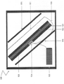
図2は、典型的な反応性装甲モジュール20の断面を示す。前記反応性装甲モジュール20は、前面板21、背面板22、および前記2つの板の間の高性能炸薬23を有する。前述のように、前記反応性装甲の顕著な有効性は、主として2つの基本的メカニズムに起因する。第1に、前記移動板は、前記成形炸薬のジェットの衝突時の有効速度および角度を変化させ、前記ジェットの入射角を変化させて前記ジェットの集中度を低下させる。第2には、前記板は前記成形炸薬の弾頭の典型的な衝突方向に対しても角度がついているので、かつ、前記板は外向きに移動するので、前記移動板の上の衝突点は時間と共に変化し、前記ジェットは前記板の新しい板材部分を切断する必要があり、事実上、着弾時に有効板厚が増大する。
FIG. 2 shows a cross section of a typical
典型的な反応性装甲は、RPG7、TOW、LOW等の一段ロケット推進式HEAT成形炸薬弾頭を迎撃するのに非常に有効であることを示しているが、しかしながら、RPG−29等のタンデム弾頭を迎撃することができない。 Typical reactive armor has been shown to be very effective in intercepting single-stage rocket-propelled HEAT-formed explosive warheads such as the RPG7, TOW, and LOW, however, tandem warheads such as the RPG-29. Cannot intercept.
図3は、本発明の一実施形態による反応性装甲モジュール30の構造を示す断面図である。反応性装甲30は独立型モジュールとすることができ、または既存の反応性装甲モジュールの追加モジュールとすることができる。後者の場合、反応性装甲30は、一般的な反応性装甲モジュール(図2の20)の前部に、またはモジュール20の後部におくことができる。特定の実施形態では、モジュール30とモジュール20との間に空間をおくことができる。
FIG. 3 is a cross-sectional view showing the structure of the
本発明のモジュール30は前面板31、および背面板32を有する。一実施形態では、前記板は、鋼鉄、バリスティック・アルミニウム、チタン、アルミナ等のなんらかの剛性材料、または前記材料の合成物で作られる。別の実施形態では、板31および32は、Dynema、Spectra、Aramid等の、ポリマーまたは類似の特性を有する材料で作られる。別の実施形態では、板31および32は、ポリマーと剛性材料を組み合わせたもので作ることができる。さらに別の実施形態では、前面板31および背面板32は、それぞれ、異なる材料または異なる材料の組み合わせで作ることができる。
The
モジュール30は、さらに、前面板31と背面板32との間に2つの内層を有する。前記2つの内層の第1の層は粒子層33であり、前記2つの内層の第2の層は高性能爆薬層34である。
The
粒子層33は複数の剛体粒子を含む。例えば、前記剛体粒子は、球形、円筒形、または飛来するタンデム弾頭との衝突を確実にし、前記タンデム弾頭への貫入を確認する可能性を最大限にするように特別に設計された形状を持つことができる。いくつかの実施形態では、種々の形状を組み合わせたものを使用することができる。
The
また、挿入図に示すように、粒子3311は軽量材料3313の層と外殻3314に囲まれた鉄心3312を有することができる。その結果、粒子3311が相互に離間し、爆薬層34が爆発したときに互いに干渉することがない。
Further, as shown in the inset, the
図4は、本発明のいくつかの実施形態の反応モジュール30の動作方法の概略を示す図である。2つの反応性装甲板30と20は一方が他方の前に置かれる。タンデム弾頭50が前面にある反応性装甲板30の前面板31に衝突すると、前記タンデム弾頭の第1の信管が爆発を引き起こして、前記前面板を突破するジェットを作り出す。前記ジェットが粒子層33を突破すると、前記ジェットは最終的に高性能爆薬層34に衝突して、前記爆薬層の爆発を引き起こし、この爆発が前記粒子をタンデム弾頭50の主(第2)炸薬に向かって射出する。これらの粒子は、前記タンデム弾頭の飛来する第2の部分に向かって射出され、第2の弾頭の前記第2の部分の爆発が引き起こされる前に、この第2の部分に超高速で衝突する。超高速で進む前記金属粒子の前記衝突は、前記タンデム弾頭の前記第2の部分の故障のない完全な状態を毀損し、結合し集中したジェットを形成するタンデム弾頭の能力を著しく損なう。場合によっては、多数の粒子が前記第2の部分に命中すると、前記第2の部分の主炸薬を爆発させることはできないとしても、前記第2の部分を全く無役にすることができる可能性がある。
FIG. 4 is a diagram showing an outline of an operation method of the
本明細書で以降、より詳細に説明するが、反応性装甲層30は、爆発のタイミングの制御を可能にする、トリガ・スクリーンを含むことができる。
As described in more detail herein, the
一実施形態では、前記粒子は、前記ジェットが引き起こす機械的衝撃によって引き起こされる前記粒子間の運動エネルギーのやりとりを低減するために離間して置くことができる。前記粒子間の離間は、各粒子を柔らかい材料、例えば、アルミニウム、ポリマー、又は、エネルギー吸収膨張材料で被覆することで実現することができる。これは、図3と粒子3311を参照して上記で説明したものである。代替的には、エネルギー吸収要素を前記粒子間においてもよい。さらに別の代替方法では、前記高性能炸薬は前記粒子間に混合することもできる。さらに別の実施形態では、前記粒子間に炸薬を混合するのに加えて、高性能炸薬の背面層が設けられる。別の実施形態では、前記粒子層と前記前面板との間に追加の爆薬層を設けることができる。別の実施形態では、前記炸薬を損傷する可能性のある前記金属粒子への前記ジェットの運動衝撃による前記高性能爆薬層への損傷を防止するために、前記粒子と前記高性能爆薬層との間に剛性材料または複合材料の層を配置することができる。
In one embodiment, the particles can be spaced apart to reduce the exchange of kinetic energy between the particles caused by the mechanical impact caused by the jet. The separation between the particles can be achieved by coating each particle with a soft material, such as aluminum, polymer, or energy absorbing expansion material. This has been described above with reference to FIG. 3 and
別の実施形態では、ケーシングの断面構造は、所望の粒子雲のベクトルおよび形状を生成するように前記爆発のエネルギーを誘導する構造に設計される。例えば、前記高性能爆薬は湾曲した形状に成形される、または傾斜もしくは湾曲したケーシングの中に配置される。以下にいくつかの例を示す。さらに別の代替方法では、剛性材料が成形された爆薬の一部の上に配置され、飛散粒子相互間の時間差爆発を起こすことができる。別の態様では、爆発時に前記粒子ベクトルに前記爆風の効果を与えられるように、ピラミッド型要素等の幾何形状要素がその先端部を爆薬層に向けて前記粒子間に挿入される。 In another embodiment, the cross-sectional structure of the casing is designed to induce the energy of the explosion to produce the desired particle cloud vector and shape. For example, the high explosive is molded into a curved shape or placed in an inclined or curved casing. Some examples are shown below. In yet another alternative, the rigid material can be placed on top of a portion of the molded explosive to cause a staggered explosion between the scattered particles. In another aspect, a geometric element, such as a pyramid-shaped element, is inserted between the particles with its tip towards the explosive layer so that the particle vector is given the effect of the blast during an explosion.
本発明の実施形態の反応モジュール30は、前面板31の前に追加の前面層を有することもできる。このような追加の前面層は、前記タンデム弾頭との衝突時に、電子的信号か、または、前記追加の前面層に装着された爆発物によって引き起こされる連続的な爆風のどちらかで反応性装甲モジュールを作動させるトリガリング機構として使用することができる。
The
別の実施形態では、近接信管または近接センサを1つまたは複数の反応性装甲モジュール30と結合させて、タンデム弾頭が前面板と衝突する前に爆発を作動させるようにすることができる。
In another embodiment, a proximity fuze or proximity sensor can be combined with one or more
図5は、さらに別の実施形態による反応モジュールの概略構造を示す。前述の実施形態とは反対に、図5の反応モジュールは、本技術分野で内破という周知の効果を利用するように設計され、前記反応モジュールの前記爆風は飛来するHEATジェットに向けられ、前記爆風の波は所定の構造で配置された剛体粒子からなるボディの中に向かい、前記構造を内部崩壊させ、前記構造を形成していた前記剛体粒子が相互の相対的位置を動的に変化させるときに、前記飛来するジェットに多方向運動衝撃を何度も加えて、前記飛来するジェットを運動している前記剛体粒子と何度も相互作用させることにより前記飛来するジェットを変形させる。このとき、各剛体粒子の衝突時の角度、速度、表面等は、前記剛体粒子が形成されたときだけでなく、前記HEATジェットの初期貫通段階においてもHEATジェットに影響を及ぼす。さらに、前記初期衝突の後でも、前記内破の残留爆発エネルギーによって前記剛体粒子がその崩壊作用を継続するので、前記HEATジェットの後尾への衝突が継続する。反応モジュール130は、前面板131、背面板132、前面板131の後面に装着された前面爆薬層134、および粒子層133を含む。本実施形態の爆薬層134は、前面板131の後面のほぼ全領域を覆う。前記HEAT炸薬による衝撃を受けると、爆薬層134は起爆され、前記剛体粒子の前記構造を自己崩壊させる爆発を起こし、上述のように内破し、そして、前記剛体粒子が多方向から前記HEATジェットに大きな運動エネルギーを加えることを引き起こすことにより、効果的に、前記ジェットに損傷を与え、前記ジェットを崩壊させる。
FIG. 5 shows the schematic structure of the reaction module according to yet another embodiment. Contrary to the aforementioned embodiment, the reaction module of FIG. 5 is designed to take advantage of the well-known effect of internal rupture in the art, and the blast of the reaction module is directed at an incoming HEAT jet, said. The wave of the blast goes into a body composed of rigid particles arranged in a predetermined structure, internally collapses the structure, and the rigid particles forming the structure dynamically change their relative positions with each other. Occasionally, a multi-directional motion impact is applied to the flying jet many times to cause the flying jet to interact with the moving rigid particles many times to deform the flying jet. At this time, the angle, velocity, surface, etc. of each rigid particle at the time of collision affect the HEAT jet not only when the rigid particle is formed but also at the initial penetration stage of the HEAT jet. Further, even after the initial collision, the rigid particles continue their collapsing action due to the residual explosive energy of the implosion, so that the collision with the tail of the HEAT jet continues. The
図6は、本発明の一実施形態による反応モジュール130のさらに別の実施形態を示す。反応モジュール130は、前面板131、背面板132、前面板131の後面に装着された前面爆薬層134、および粒子層133を有する。本実施形態の爆薬層134は、前面板131の後面の実質的に全領域を覆い、また、前記反応モジュールの側板に沿って延長部141を有する。前記HEAT炸薬の衝突時に、前記爆薬層は、前記爆発波に沿って前記剛体粒子を放出させる爆発を起こすように起動される。前記爆発波が爆発層の非対称幾何形状から出たとき、前記爆発波の軌跡ははっきりしていない。と言うよりむしろ、各表面から出た爆発波は前記粒子を一つ以上の方向に動かして、前記飛来するHEATジェットに多数の力学的力を加え、前記ジェットを効果的に崩壊させる。任意ではあるが、前記爆薬の幾何形状は、衝撃波中心を多数作り出すために多様な形であり、前記粒子が多数の方向から前記ジェットに大きな運動エネルギーを加えるように前記粒子を射出して、前記ジェットを効果的に破壊する。さらに、爆発によって生成される前記衝撃波の焦点は、当該技術分野でモンロー効果として知られる方法で指向性爆発波を生成するように前記爆薬の幾何学的構造を成形することにより、方向付けかつ/または強化することができる。前記HEATジェットとの衝突コース、または、結局は前記HEATジェットに影響を与えることになる2次的衝撃を前記粒子に対して与えるような他の粒子との衝突コースに向けて、前記粒子を発射するように、前記衝撃波を所与の方向に向けさせ、かつ、増幅する形状に、爆風レンズ140が形成される。一つの実施形態では、前記爆風のある部分は前記爆風レンズによって焦点が合わせられるが、他の部分はそうでない。この効果は、前記爆風レンズ140の中にライナーを挿入することによって高めることができる。他の実施形態では、前記爆風レンズの前記働きは、前記剛体粒子の軌道を所望のコースまで誘導し、前記衝撃波を分散させることができる。
FIG. 6 shows yet another embodiment of the
図7は、本発明のさらに別の実施形態を示す。図6の爆薬層の延長部141は、片側表面を完全に覆っているのに対して、延長部141aは表面の一部しか覆っていない。さらに、図6の実施形態では、延長部141が1つしかないが、図7の実施形態は第2の延長部141bを有し、第2の延長部141bは、この例では、前記反応性装甲モジュール130の反対側の角に配置されている。延長部141bは、前記側面全体を覆うことができる。好ましくは、2つの延長部141aおよび141bは、図示のように異なる軸線上に配置される。前記HEAT炸薬の衝撃を受けると、前記爆薬層は、前記剛体粒子を前記爆発波に沿って発射させるような爆発を起こすように起爆される。爆発波には、(本実施形態での爆薬層の非対称幾何形状の効果として)複数の中心があるので、前記飛来するHEATジェットが炸薬134の爆発を引き起こす衝突時に、各表面からの前記爆発波は、前記粒子を複数の方向に連続的に動かすことができる。前記爆発点は延長部141aまたは延長部141bのどちらかに近接させることができるので、前記爆発は、前記延長部の一方に他方よりも早く到達することができる。前記爆発が、確実に非同時的に起こるようにするために、延長部141aおよび141bに異なるタイプの爆薬を使用することができる。さらに、2つの延長部は、爆風イールド効果の低下を防止するために、厳密な一直線上では対向していない。別の実施形態では、側面141aおよび141bに隣接する剛体粒子は、それぞれ異なる質量、異なる形状、異なる整列構造のうちの1つまたは複数を有する。さらに、前記粒子は、異なる密度かつ異なる粒子配列、異なる引張り強度の複数の材料に埋め込むことができる。
FIG. 7 shows yet another embodiment of the present invention. The
前記非対称構造により生成される多数の力学的力は、前記ジェットを効果的に崩壊させる。また本実施形態では、図6と同様に、前記爆薬の前記幾何形状は、衝撃波の中心を多数作り出すために多様にすることができ、これにより、前記粒子が一つ以上の方向から前記ジェットに高運動エネルギーを加える、前記ジェットを効果的に破壊するように、前記粒子を発射することができる。さらに、爆発によって生成される前記衝撃波の焦点は、当該技術分野でモンロー効果として周知の方法で指向性爆発波を生成するように前記爆薬の幾何学的構造を成形することにより、方向付けかつ/または強化することができる。爆風レンズ140(図6に示す)は、前記衝撃波を所与の方向に向けた形状にし、方向付けをし、かつ増幅させるように、かつ、前記HEATジェットとの衝突コース、または、結局は前記HEATジェットに影響を与えることになる2次的衝撃を前記粒子に対して与えるような他の粒子との衝突コースに向けて、前記粒子を発射するように、前記爆薬層の1つまたは複数の箇所に組み込むことができる。この効果は、前記爆風レンズ140の中にライナーを挿入することによって増強することができる。代替実施形態では、前記爆風レンズの機能を変更して、前記剛体粒子の所望のコースまでの軌跡を生成するように前記衝撃波を分散させることができる。
The numerous mechanical forces generated by the asymmetric structure effectively collapse the jet. Further, in the present embodiment, as in FIG. 6, the geometry of the explosive can be varied to create a large number of shock wave centers, whereby the particles can be directed into the jet from one or more directions. The particles can be fired to effectively destroy the jet, which applies high kinetic energy. In addition, the focus of the shock wave produced by the explosion is oriented and / by shaping the explosive geometry to generate a directional explosive wave in a manner well known in the art as the Monroe effect. Or it can be strengthened. The blast lens 140 (shown in FIG. 6) shapes, directs, and amplifies the shock wave in a given direction, and has a collision course with the HEAT jet, or, in the end, said. One or more of the explosive layers to fire the particles towards a collision course with other particles that would exert a secondary impact on the particles that would affect the HEAT jet. Can be incorporated in places. This effect can be enhanced by inserting a liner into the
図8は、本発明のさらに別の実施形態による3層構造反応モジュールを示す。前記3層は単なる例に過ぎず、さらに別の層を追加して別の実施形態を構成できることは容易にわかるであろう。反応性モジュール230は、ストライク面231と、後面232と、第1爆薬層234と、第2爆薬層235と、第3爆薬層236と、第4爆薬層237とを含む。第1スチール壁246は、開口246a、246b、及び246cを有し、第1爆薬層234と第2爆薬層235との間に配置され、第1爆薬層234と第2爆薬層235とを分離する。爆薬層234,235,236、および237は、単一の比較的反応速度が速い爆発性材料で構成することができる。第1の粒子と爆発物の構造233aが前記ストライク面と第1の鋼鉄壁246との間に配置され、鋼鉄壁246の背後に第2の粒子と爆発物の構造233bが配置される。セパレータ239は、第2の粒子と爆発物の構造233bと第3の粒子と爆発物の構造233cとを分離する。構造233aは、爆薬層234〜237の爆薬よりも反応が遅い爆薬で構成することができる。構造233bは、さらに反応が遅い爆薬で構成することができる。構造233cは、他のすべての構造の爆薬よりも反応が遅い爆薬で構成することができる。HEATジェットと衝突すると、爆薬層234が爆発し、剛性粒子を様々な方向に射出し、それにより、前記飛来する弾頭の主炸薬を破壊する。
FIG. 8 shows a three-layer structure reaction module according to yet another embodiment of the present invention. It will be easy to see that the three layers are merely examples, and that another layer can be added to form another embodiment. The
前記層の間の爆発の進展は明確には決まらず、いくつかの進展経路が可能である。例えば、前記爆発が第1の粒子構造233a内で始まると、爆風は開口246内を伝搬して第2の主爆薬層235を作動させ、第2の爆薬層235の即時爆発を引き起こす。第2の爆薬層235が爆発すると、上記で詳述した内破過程が粒子構造233bの中で始まり、粒子構造233bは自己崩壊する。この爆発に続いて、前記爆風は爆薬層236内を伝搬して、爆薬層237の爆破シーケンスを起動する。爆薬層237の爆発は、粒子構造233cの内部崩壊を引き起こし、このとき、粒子構造233cの粒子が崩壊した粒子構造233bと衝突する。この複数の爆発構造による内破の、複数回の発生は、前記飛来するHEATジェットを効果的に崩壊させる。より詳細には、前記非対称配列により生成された多くの力学的べクトルが、前記ジェットを効果的に崩壊させる。
The progression of the explosion between the layers is not clearly defined and several development paths are possible. For example, when the explosion begins in the
また本実施形態では、図6と同様に、前記爆薬幾何形状は、多数の衝撃波中心を作り出すように変えることができ、これにより、前記粒子を射出して前記粒子を二つ以上の方向から前記ジェットに大きな運動エネルギーを加え、前記ジェットを効果的に破壊することができる。さらに、当該技術分野でモンロー効果として周知の方法で指向性爆発波を生成するように前記爆薬の幾何学的構造を作ることによって爆薬を成形することにより、爆発によって生成される前記衝撃波の集束の方向付け及び/または増幅を行うことができる。爆風レンズ140(図6に示す)は、前記衝撃波を所与の方向に向けた形状にし、方向付けをし、かつ増幅させるように、かつ、前記HEATジェットとの衝突コース、または、結局は前記HEATジェットに影響を与えることになる2次的衝撃を前記粒子に対して与えるような他の粒子との衝突コースに向けて、前記粒子を発射するように、前記爆薬層の1つまたは複数の箇所に組み込むことができる。この効果は、前記爆風レンズ140の中にライナーを挿入することによって増強することができる。代替実施形態では、前記爆風レンズの機能を変更して、前記剛体粒子の所望のコースまでの軌跡を生成するように前記衝撃波を分散させることができる。前記鋼板またはセパレータ内に前記開口を含めることは任意選択であることは容易にわかるであろう。
Further, in the present embodiment, as in FIG. 6, the explosive geometry can be changed to create a large number of shock wave centers, whereby the particles are ejected and the particles are ejected from two or more directions. A large amount of kinetic energy can be applied to the jet to effectively destroy the jet. In addition, the focusing of the shock wave generated by the explosion by shaping the explosive by creating a geometric structure of the explosive so as to generate a directional explosive wave by a method well known in the art as the Monroe effect. It can be oriented and / or amplified. The blast lens 140 (shown in FIG. 6) shapes, directs, and amplifies the shock wave in a given direction, and has a collision course with the HEAT jet, or, in the end, said. One or more of the explosive layers to fire the particles towards a collision course with other particles that would exert a secondary impact on the particles that would affect the HEAT jet. Can be incorporated in places. This effect can be enhanced by inserting a liner into the
この例は非限定的なものである。その理由は、1つまたは複数の爆薬層を遮蔽し、それによって爆薬層の崩壊が時期尚早に発生することを防止するために、追加のセパレータ、レンズ、または鋼板を使用することができるからである。さらに、前記鋼板を補強するために、上述のように、アルミナ98やシリコン・カーバイド等の材料が前記反応モジュールの一部として使用してもよく、また、ポリマー等の複数の種々の材料または多様な幾何形状を有する中空構造を、上述したような、前記モジュールの最終結果に影響を及ぼす可能性のある爆風誘発力と物理的および機械的効果とを方向付け、強化し、弱化させること、等のために使用できることにも留意して頂きたい。本発明の前記反応モジュールの使用は、独立型モジュールとして、あるいは他のモジュール、すなわち本明細書に記載のモジュールか、または従来技術から既知のモジュールと組み合わせて、実行することができることに留意して頂きたい。 This example is non-limiting. The reason is that additional separators, lenses, or steel sheets can be used to shield one or more explosive layers and thereby prevent the explosive layer from collapsing prematurely. be. Further, as described above, materials such as alumina 98 and silicon carbide may be used as part of the reaction module to reinforce the steel sheet, and a plurality of different materials or varieties such as polymers. To direct, strengthen, weaken, etc., blast-inducing forces and physical and mechanical effects that may affect the final result of the module, as described above, for hollow structures with similar geometric shapes, etc. Please also note that it can be used for. It should be noted that the use of said reaction modules of the present invention may be carried out as stand-alone modules or in combination with other modules, i.e. the modules described herein or known from the art. I would like to have it.
前記典型的な反応性装甲は、一般に、垂直方向に対して斜めにして実装することは容易にわかるであろう(この状態は、図2および図4には概略的にも示されていない)。 It will be readily apparent that the typical reactive armor is generally mounted at an angle to the vertical direction (this condition is also not shown schematically in FIGS. 2 and 4). ..
本発明の別の実施形態では、本発明の前記ERA内での爆破シーケンスの時間制御起動を可能にするために、トリガ・スクリーンが設けられる。トリガ・スクリーンは当技術分野で周知である。例えば、図9に示すトリガ・スクリーン、モデル番号PT−0303500600MKは、ホイスナーコーポレーション(Whithner Corporation、米国企業)によって製造されている。トリガ・スクリーンは、一般的には、トリガ・スクリーンの貫通時に電気回路を閉じるために使用される。前記トリガ・スクリーンへの貫入時、電気回路が閉じられ、起爆回路が起動されて、前記炸薬の爆発を起こす。トリガ・スクリーンは、代替的には、ピエゾ素子によって作ることができる。このピエゾ素子は、爆発事象に起因する圧力の発生時に電流を生成する素子である。または電磁場の検出によって起爆装置を作動させることができる。本明細書の、トリガ・スクリーンに言及している全ての場所において、爆破タイミング制御または爆破シーケンス制御を実行する他の手段が含まれることを理解されたい。 In another embodiment of the invention, a trigger screen is provided to allow time-controlled activation of the blast sequence within said ERA of the invention. Trigger screens are well known in the art. For example, the trigger screen shown in FIG. 9, model number PT-0303500600MK, is manufactured by Whithner Corporation (US company). Trigger screens are commonly used to close electrical circuits as they penetrate the trigger screen. Upon entry into the trigger screen, the electrical circuit is closed and the detonation circuit is activated, causing the explosive charge to explode. The trigger screen can be made by an alternative piezo element. This piezo element is an element that generates an electric current when pressure is generated due to an explosion event. Alternatively, the detonator can be activated by detecting an electromagnetic field. It should be understood that all places referred to herein in the trigger screen include other means of performing blast timing control or blast sequence control.
爆破シーケンスの遅れ時間は当技術分野で知られる手段で制御することができ、例えば、トリガ・スクリーンの貫通時刻から5〜20マイクロ秒で爆破シーケンスが始まることを可能にする。爆薬層134または前記炸薬で重要と考えられる他の部分から前記トリガ・スクリーンまでの距離は、前記ジェットによる衝撃を受ける前に前記爆発を起こすようにする統御を可能にする大きな要素である。図9〜図9Cに示すように、トリガ・スクリーン241は、高性能爆薬層134の爆風の時間制御をするために使用される。本発明の複数の実施形態によれば、この種のトリガ・スクリーン241は前記ストライク面の後部に実装される。爆薬層134からトリガ・スクリーン241までの距離は、前記ジェットが図9Bの前記ERA内の要素に衝突する前に前記炸薬内で爆破シーケンスを開始することができるまでの最大時間を決定するように調整することができる。図9Cでは、前記スクリーンは、例えば、前記炸薬を構成する要素内に配置される。前記ジェットが前記炸薬を構成する前記要素の中を通り抜けるとき、前記ジェットが前記炸薬内の設定した箇所に飛来する前に、前記炸薬は爆破シーケンスを起動する。
The delay time of the blast sequence can be controlled by means known in the art, for example, allowing the blast sequence to begin 5 to 20 microseconds from the penetration time of the trigger screen. The distance from the
この種の技術は、従来技術のERAモジュール20(図2参照)をトリガして、前記成形炸薬のジェットが前記高性能爆薬を挟む前記前面鋼板に衝突する前にERAモジュール20を爆発させるためにも使用できることは容易にわかるであろう。トリガ・スクリーン241(図9Aに示す)を使用する前記トリガ機構を利用すると、図2の前記ERAモジュールが前記ジェットを迎撃する可能性を劇的に高めることができることも容易にわかるであろう。図9A、9B、及び9Cは、ERA20の前面板21の前に所定の距離を置いて配置されたスクリーン241を示す。前記起爆装置は、図9A、9B、及び9Cで数字243として示されている。前記爆発回路は、通常品であり、簡潔にするために上記の図には示されていない。
This type of technique triggers the prior art ERA module 20 (see FIG. 2) to explode the
上述のトリガ・スクリーン241は、前記飛来するジェットと前記ERA内の所定の要素が衝突する前に爆破シーケンスを起動するために、当技術分野で周知の他の手段によって増強または置換することができることも容易にわかるであろう。
The
図9に示すように、トリガ・スクリーン241は、2つ以上の別個のスクリーン241a及び241bに分割することができる。分割されたトリガ・スクリーンのうち、最初に作動された方が、前記反応性装甲の特定の場所から爆発を開始することができる。したがって、異なる方向からのミサイル攻撃に対しては、異なる爆発波ベクトルによって防御することができる。
As shown in FIG. 9, the
図9Aについてより詳細に説明する。図9Aは、上述のように爆薬層21を起爆する起爆装置243をトリガするためのトリガ・スクリーン21を追加した、典型的な反応性装甲モジュールを断面形状でより詳細に示す。トリガ・スクリーン241は、空間2412内のストライク面2410の背後から所定の距離の位置に配置されている。空間2412は、所定の大きさであり、ストライク板2410と前部鋼板21との間に配置されている。前部鋼板21は、後部鋼板22の前方に配置されている。
FIG. 9A will be described in more detail. FIG. 9A shows in more detail a typical reactive armor module in cross-sectional shape, with the addition of a
前記空間は、任意のサイズでよく、空隙でもよいし、例えばポリマー等で充填されていてもよい。上述のように、スクリーン241は起爆装置243に接続されており、両者の距離は、前記トリガ・スクリーン作動後の正確な所定の時間に爆薬層23を起爆するように設定される。
The space may be of any size, may be voids, or may be filled with, for example, a polymer. As described above, the
図9Bは、図7に示す反応性装甲モジュールに本実施形態のトリガ・スクリーンを付加した反応性装甲モジュールの断面形状を示す。トリガ・スクリーン241は、空間2412内のストライク面2410の背後に所定の距離だけ離れて配置されている。空間2412は、所定の大きさであり、ストライク板2410と前部鋼板21との間に配置されている。前部鋼板21は、後部鋼板22の前方に配置されている。
FIG. 9B shows a cross-sectional shape of the reactive armor module in which the trigger screen of the present embodiment is added to the reactive armor module shown in FIG. 7. The
前記空間は、任意のサイズでよく、空隙でもよいし、例えばポリマー等で充填されていてもよい。上述のように、スクリーン241は起爆装置243に接続されており、両者の距離は、前記トリガ・スクリーン作動後の正確な所定の時間に爆薬層23を起爆するように設定される。延長部141aおよび141bは、前記爆発物の全体的分布と相まって、前記爆発波面の高度な破壊性を確実にする。
The space may be of any size, may be voids, or may be filled with, for example, a polymer. As described above, the
図9Cは、図8に示す反応性装甲モジュールに本実施形態のトリガ・スクリーンを付加した反応性装甲モジュールの断面形状を示す。トリガ・スクリーン241は、ストライク面2410の背後の空間2412内に所定の距離だけ離れて配置されている。空間2412は、所定の大きさを持ち、ストライク板2410と前部鋼板246との間に配置され、第1爆薬層233aを含む。前部鋼板246は、複数の開口246a、246b、及び246cを有し、爆薬層233bと233cの前方に配置され、爆薬層233cは同様に後部鋼板232の前方に配置されている。
FIG. 9C shows a cross-sectional shape of the reactive armor module in which the trigger screen of the present embodiment is added to the reactive armor module shown in FIG. The
空間2412は、任意のサイズでよい。前述のように、スクリーン241は、起爆装置243に接続され、両者の距離は、破壊力のある波面を生成するために、前記トリガ・スクリーンが起動された後、爆薬層233a、233bおよび233cを正確に時間遅延 された順序で爆発させるように設定される。
The
図9Dを参照して説明する。図9Dは、図9Bの前記粒子が、鋼材層を複数層重ねたものに置き換わっていることを示す。鋼材層の各々は爆発物の層が背後にある。前記モジュールの両側の2つの炸薬が爆発され、はさみ効果を引き起こす。 This will be described with reference to FIG. 9D. FIG. 9D shows that the particles of FIG. 9B are replaced by a plurality of steel layer layers. Each of the steel layers is behind a layer of explosives. Two explosives on either side of the module explode, causing a scissors effect.
図10は、本発明の別の実施形態を開示する。本実施形態では、爆薬層234は、水平面か垂直面のどちらかに対していくらか傾斜するように形成または成型される。前記反応性装甲の炸薬の前記構成では、爆発時、粒子構造233は、粒子構造233に衝突しようとする前記ジェット277に斜め方向のせん断力を加えながら、前記飛来するHEATジェットに向かって発射される。図11に示す別の実施形態では、前記反応性装甲は、前記傾斜した爆薬層234に加えて、配線278を介して前記爆破シーケンスを作動させ、その結果、前述のように、起爆装置243を爆発させるためのトリガ・スクリーン241を有する。前記トリガ・スクリーンは、電磁信号または無線周波数(RF)信号を生成するために電気回路を閉路する手段として使用することができる。前記信号は、適切な受信機によって受信され、次に、起爆装置243を作動させることができる爆破シーケンスを始動する。
さらに別の実施形態では、前記爆破シーケンスを始動することができるトリガ・スクリーン、又は他の装置を、1つ以上の反応性装甲モジュールに接続することができる。または、図9に関して説明したように、前記トリガ・スクリーンを分割して、前記飛来する飛翔体の方向によって、異なるトリガ・シーケンスを前記反応性装甲ユニット内で実行することができる。
FIG. 10 discloses another embodiment of the present invention. In this embodiment, the
In yet another embodiment, a trigger screen, or other device, capable of initiating the blast sequence can be connected to one or more reactive armor modules. Alternatively, as described with respect to FIG. 9, the trigger screen can be split to perform different trigger sequences within the reactive armor unit depending on the direction of the flying projectile.
前記トリガ・スクリーンは、例えば図11に示すように、上述の実施形態のいずれでも動作することができる。前記トリガ・スクリーン、前記スイッチング機構、または前記起爆装置へ供給する電力は、以下の手段によって得ることができる。(a)電池、(b)コンデンサ、(c)誘導型回路、(d)当技術分野で周知の方法で、ロッキング運動により振り子型素子を電磁場中で動かすことによって電気を発生させ、コンデンサや電池等に供給する電気機械素子、(e)前記HEATジェットから圧力または衝撃がかかったとき電気を発生させて前記トリガ・スクリーン内に向けることができる圧電素子、代替的には、発生させた電力で、コンデンサまたは電池内に貯蔵されたエネルギーを前記爆破シーケンスの作動のために放出させるスイッチング機構を作動させることができる圧電素子、(f)接触(前記HEATの爆発によって始動される)したとき、上述の動作に必要な電気を発生させる、当技術分野では周知の化学物質または金属の使用。 The trigger screen can operate in any of the above embodiments, for example, as shown in FIG. The electric power supplied to the trigger screen, the switching mechanism, or the detonator can be obtained by the following means. (A) Battery, (b) Capacitor, (c) Inductive circuit, (d) A capacitor or battery that generates electricity by moving a pendulum type element in an electromagnetic field by locking motion by a method well known in the art. (E) A piezoelectric element that can generate electricity when a pressure or impact is applied from the HEAT jet and direct it into the trigger screen, or, instead, a generated electric power. , A piezoelectric element capable of activating a switching mechanism that releases energy stored in a capacitor or battery for the operation of the blast sequence, (f) contact (initiated by the explosion of the HEAT), described above. Use of chemicals or metals well known in the art to generate the electricity required for the operation of the.
上記手段(b)、(e)、および(f)は、前記トリガ・スクリーンと連結して、または上述の実施形態のいずれかに記載した前記反応性装甲用のトリガ機構として使用することができる。これらの手段は、前記トリガ・スクリーンに取って代わることができ、衝突時に、前記爆破シーケンスを始動するのに必要な電力を放出することができる。好ましくは、前記要素(b)、(e)、および(f)は前記炸薬の前にいくらかの距離を置いて配置される方がよい。 The means (b), (e), and (f) can be used in conjunction with the trigger screen or as a trigger mechanism for the reactive armor described in any of the embodiments described above. .. These means can replace the trigger screen and, in the event of a collision, can release the power required to initiate the blast sequence. Preferably, the elements (b), (e), and (f) should be placed at some distance in front of the explosive charge.
図12は、高性能爆薬層162を挟む2つの鋼板160と161とを含む反応性装甲を示す。前記高性能炸薬は、図12の上部に横方向に長く描かれているトリガ・スクリーンが作動するときに、該トリガ・スクリーンによって作動される起爆装置163が固定されている。前記トリガ・スクリーンを貫通するとき、鋼板160と161との間に挟まれた高性能爆薬162との接触が始まる前に、前記トリガ・スクリーン機構によって爆発が始動され、前記高性能爆薬が爆発し、前記飛来するジェット165と前記反応性装甲サンドイッチが衝突する前に、1つまたは複数の金属板を前記飛来するジェットに向けて射出する。前記トリガ・スクリーンは、前記HEATジェットとは異なる要素による偶発的な作動を防止するためにストライク面166の背後にある。前記爆薬層は前記ストライク面に対して一定の角度がついており、前記飛来するジェットに対して一定の角度のある爆発によって、前記飛来するジェットの一点集中度を弱めることができる。
FIG. 12 shows reactive armor containing two
バッテリ167は、起爆装置163を作動させる電力を供給することができる。
The
上述の反応性装甲モジュールのすべてまたはいずれかのストライク面166が、鋼鉄、チタン、バリスティック・アルミニウム、あらゆる種類の金属合金等の剛性金属要素から構成できることは容易にわかるであろう。さらに、前記ストライク面は、アルミナや炭化ホウ素等の剛性材料から構成することができる。さらに、前記ストライク面は、アラミドやダイネマ等の各種ポリマーから構成することができる。さらに、前記ストライク面は、ガラスや炭素繊維等の圧縮繊維から構成することができる。上記材料の各々またはいずれかが、鋼鉄として図面に示されているストライク面と組み合わせるか、または置き換えることができる。同じことが、本明細書で鋼鉄層として示されている他の全ての層に適用される。
It will be easy to see that the
図13は、本発明のさらに別の実施形態を示す。図12と同一の部分には同一の参照符号を付し、本実施形態の理解のために必要な場合を除いて説明を省略する。爆薬層170は、前記飛来するジェット165を崩壊させる波面を生成するように設計された成形炸薬レンズ171を一つ又は複数含む。前記レンズは、ライナー172(当技術分野で周知)を具備していてもいなくてもよい。前記ライナーは、前記爆発のエネルギーを吸収し過ぎないようにするために、銅または同様の材料にすることができる。前記爆薬レンズは、異なる方向の衝撃に向いた構成173および174のような様々な構成で設けることができる。前記爆薬レンズを使用して作成された反応性装甲モジュールは、前記トリガ・スクリーン164を使用して前記レンズを作動させることにより、前記飛来するHEATジェット165を迎撃するために使用することができる。一実施形態では、前記モジュールの異なる部分は異なる形状のレンズを有する。さらに別の実施形態では、前記モジュールの前記異なる部分は、異なる方向からの衝撃が適切に方向付けされた爆発波と衝突するように、前記トリガ・スクリーンの異なる部分によって作動される。
FIG. 13 shows yet another embodiment of the present invention. The same parts as those in FIG. 12 are designated by the same reference numerals, and the description thereof will be omitted except when necessary for understanding the present embodiment. The
より適した方向に爆風を向けるために、前記レンズの断面形状は、三角形(図に示す)、球形、または任意の他の形状にすることができる。別の実施形態では、前記レンズは、溝または空孔を複数有する部分球形にすることができる。前記溝はライナーで充填することができる。前記溝または空孔は、力を集中させることによって前記レンズの効果を強化することができる。 In order to direct the blast in a more suitable direction, the cross-sectional shape of the lens can be triangular (shown in the figure), spherical, or any other shape. In another embodiment, the lens can be a partial sphere with a plurality of grooves or holes. The groove can be filled with a liner. The groove or hole can enhance the effect of the lens by concentrating the force.
図14は、図12に記載された、粒子ベース爆発反応性装甲モジュール720と爆発反応性装甲モジュール721とを組み合わせたものを示す。図12と同一の部分は、図12と同一の参照符号を付しており、本実施形態の理解のために必要な場合を除き、再度説明されない。反応性装甲モジュール720および721の各々には、トリガ・スクリーン164が設けられている。前記2つのトリガ・スクリーンのいずれも、前記反応性モジュールを、時間制御された爆破シーケンスで起動することができる。飛来するタンデム飛翔体722は、初期ジェット723を生成する。前記初期ジェットは、第1モジュール720のスクリーン164をトリガし、その結果発生する爆発により、粒子雲724が形成され、飛翔体722の主爆発のより大きなジェットを消滅させる。モジュール721はまだトリガされないままである。しかし、飛来する飛翔体722がモジュール720を超えて着弾する場合トリガされる。または、モジュール721は、さらに別のタンデム飛翔体の攻撃に備えて同じ場所で迎撃体勢のまま維持される。
FIG. 14 shows a combination of the particle-based
本明細書のすべての実施形態において、複数の前記モジュールは、タンデム構成のように連続的に作動することができ、例えば、複数の前記モジュールは、一つのモジュールを他のモジュールの前に、または、一つのモジュールを他のモジュールの横に、または、数個の反応性装甲モジュールのクラスタ構成にして配置される。各モジュールは、上述のように各モジュール自体のトリガ機構を有することができる、または単一のトリガ機構によってトリガすることができる。1つの反応性装甲モジュールに結合されるトリガ・スクリーンは、起動時に、他のモジュール内の爆破シーケンスを始動して、上述のように連動して作動することができる。 In all embodiments of the present specification, the plurality of said modules can operate continuously as in a tandem configuration, for example, the plurality of said modules may have one module in front of another or the other module. , One module is placed next to the other module, or in a cluster of several reactive armor modules. Each module can have its own trigger mechanism as described above, or can be triggered by a single trigger mechanism. Trigger screens coupled to one reactive armor module can, upon activation, initiate a blast sequence within the other module and operate in tandem as described above.
さらに別の実施形態では、前記HEATジェットを消滅または大きく変形させる可能性を高めるために、本出願に記載した反応性装甲モジュール、または当該技術分野で周知の反応性装甲モジュールを複数、連続配置している、すなわち、一つのモジュールを他のモジュールの前に、または、一つのモジュールを他のモジュールの上に、または、一つのモジュールを他のモジュールの横に、等のように配置して、時間間隔を制御して起動する。当技術分野で周知の1つ又は複数の反応性装甲モジュールには、爆発反応性装甲、非自動反応性装甲等がある。図15Aの非限定的な例に示す、鋼鉄層901、高性能爆薬層902、および鋼鉄層903を含む爆発性反応性装甲モジュール900は、図15Bのモジュールの前に配置される。非限定的な例では、図15Bのモジュール920は、本出願で詳細に説明したように、トリガ・スクリーン921、鋼鉄層922、高性能爆薬層923、起爆装置924、エネルギー源925、配線926、および鋼鉄層927を含む。図15Cは、図15Aの反応性モジュール900と図15Bの反応性モジュール920と、その間に充填材952,953、および954を詰めた組み合わせ構成930を示す。
In yet another embodiment, a plurality of reactive armor modules described in the present application or reactive armor modules well known in the art are arranged in succession in order to increase the possibility of extinguishing or significantly deforming the HEAT jet. That is, one module is placed in front of another module, one module is placed on top of another module, one module is placed next to another module, and so on. Start by controlling the time interval. One or more reactive armor modules well known in the art include explosive reactive armor, non-automatic reactive armor and the like. The explosive
前記充填材は、共通のケーシング内の前記反応性モジュールを支持するために使用され、かつ/又はモジュール900及び920の前記鋼板の減速又は加速を可能にし、さらに、散逸する残存爆発エネルギーの維持を可能にする。前記充填材は、高密度発泡スチロール、低密度発泡スチロール等の異なる密度のポリマー、または、機械的支持を提供するように成形することができる任意の材料で作ることができる。前記機械的支持は、空孔を材料に挿入して、かつ/またはハニカム構造のような重量を支持することができる機械的構造を構築して、面密度を交互に変えること、あるいは、流体のようなエネルギー吸収材料を前記任意の材料に挿入すること、または、空孔952,953、および954に配置された容器内に水等の流体を含有させることによって達成される。さらに、前記充填材は、発泡スチロール等をベースとする剛性材料を製造するために、ガスのポンピングによる製造と同様にして、異なる面密度を有する金属を含む複合材料で製造することができる。さらに、モジュール900および920の各々の中の異なる質量の鋼板を使用することによって、前記モジュールの爆発の残留効果の間の相互作用を、爆発波と前記鋼鉄要素との間の所定の衝突パターンに従うように修正することができる。
The filler is used to support the reactive module in a common casing and / or allows deceleration or acceleration of the steel plates of
例えば、モジュール920の鋼板922および927が異なる質量を有する場合、前記鋼板は、前記爆発の残留効果との相互作用だけでなく、反対方向にかつ/または異なる速度で飛んで行き、必要と考えられる程度に、より高速またはより低速で前記HEATジェットに衝突することができる。衝突時には、HEATジェット940の先端は、モジュール900および920を爆発させる。モジュール930全体の効率を最適化するために、以下のパラメータを調整する。(a)モジュール900と920との間の距離、(b)モジュール900と920との間の相対角度、(c)充填材952,953および954の材料特性および機械的特性、(d)使用される高性能爆発物の技術的特性、その重量(1モジュール当たりの密度)、およびモジュール900および920のそれぞれにおいて異なる質量を持つ異なる爆薬を使用することの技術的利点、(e)起爆装置の技術的特性、または、図15Dに示すような単一モジュールへ複数の起爆装置を配置する技術的利点、(f)爆発の始動を可能にするために爆発用配線を使用する場合の爆発用配線の特性。
For example, if the
前記爆発物の技術的特徴には、前記爆発物の爆発速度が含まれる。例えば、層900は最も遅い層にすることができる。層920は、より高速な層にすることができ、例えば、トリガ・スクリーンを使用して作動させることができる。第3の層を、前記飛来する飛翔体の方向に向けて前方に追加することができ、さらに、追加する層を超高速な層にして、トリガ・スクリーンによって作動させることができる。他の適切な組み合わせを使用してもよい。図15Bでは単一の起爆装置924を使用しているが、図15Dにはいくつかの起爆装置をモジュール920内で使用する実施形態を示す。より詳細には、図15Dは複数の起爆装置924A〜924Nの配列の上面図を示している。図15Bの起爆装置924のような起爆装置が起動されると、爆発始動時から高性能爆薬の全質量が消費される時までに設定した時間量が経過する。前記高性能爆発物の塊の全体923(図15B)が爆破される時間を最短化し高速化するために、複数の起爆装置を前記高性能爆発物の中に分散させ、より均一な爆発を起こすために同時に作動させることができる。または、順番に爆発させるために特定の方向に向いた起爆装置を設けることができる。前述のような複数の起爆装置の使用は、本発明の様々な実施形態の全てに適用することができる。
The technical features of the explosive include the explosive velocity of the explosive. For example,
前記鋼板に前記HEATジェットが加えるエネルギーは、鋼鉄をチタンのような金属合金で置き換えても、図15Aのような反応性モジュールの全体的な性能にほとんど差が生じない程度のものなので、現在は反応性装甲モジュールに鋼鉄が使用される。すなわち、同じ厚さが要求される。図15Bに示すような本発明の実施形態では、鋼鉄は、チタンおよびアルミニウム合金のような低密度材料に置き換えることができる。バリスティック・アルミニウムおよびチタン合金を使用すると、大量の部材が前記飛来するHEATジェットに向かって発射されるため、大幅な性能向上を実現できた。高速のより厚い移動板と前記飛来するジェットとの相互作用は非常に効率的であることが証明されており、飛来するHEATジェットに対して発射されるチタンの等価質量が、前記ジェットの鋼鉄製の目標物への貫通を防止する効率は、同じ質量の鋼鉄を使用する反応性装甲モジュールと比較して、250%高い。さらに、図15Aの反応モジュールと図15Bの反応モジュールとを同じ量の高性能爆薬とバリスティック・アルミニウムとチタン合金とを用いて比較すると、バリスティック・アルミニウムとチタン合金を使用する場合、前記ジェットの鋼鉄製目標物への貫通を150%の効率で防止するという点で、非常に優れた性能(150%)が得られた。 The energy applied to the steel sheet by the HEAT jet is such that even if the steel is replaced with a metal alloy such as titanium, there is almost no difference in the overall performance of the reactive module as shown in FIG. 15A. Steel is used for the reactive armor module. That is, the same thickness is required. In embodiments of the invention as shown in FIG. 15B, steel can be replaced with low density materials such as titanium and aluminum alloys. When ballistic aluminum and titanium alloys are used, a large amount of members are fired toward the flying HEAT jet, so that a significant performance improvement can be realized. The interaction of the faster, thicker moving plate with the incoming jet has proven to be very efficient, and the equivalent mass of titanium fired against the incoming HEAT jet is made of steel in the jet. The efficiency of preventing penetration of the target is 250% higher than that of reactive armor modules using the same mass of steel. Furthermore, comparing the reaction module of FIG. 15A and the reaction module of FIG. 15B with the same amount of high performance explosive, ballistic aluminum and titanium alloy, when ballistic aluminum and titanium alloy are used, the jet Very good performance (150%) was obtained in terms of preventing penetration of the steel target into the steel target with an efficiency of 150%.
図16は、二つの反応性モジュール820および821を示す。単一トリガ・スクリーン832は、2つの反応性モジュール820及び821を作動させる時間制御爆破シーケンスをトリガするために使用され、反応性モジュール820及び821は一方が他方の前に配置される。前記モジュールは、図示のように空間で分離してもよいし、接触していてもよい。トリガ・スクリーン832は、トリガ・スクリーン832を含む反応性装甲820と、トリガ・スクリーン832が接続線841によって接続される反応性装甲821の両方を作動させる。接続線841には、有線接続、誘導、RF(無線)、または当技術分野で周知の他の接続手段が含まれる。さらに別の実施形態では、トリガ・スクリーン832は、反応モジュール820内に収容されているが、他の反応モジュール821のみを作動させるようにすることができる。その場合、反応モジュール820は、前記HEATジェットの衝撃によって作動する。さらに別の実施形態では、モジュール820は、粒子を含まず、高性能爆薬のみを含むことができる。図16の上記説明は、例示であり、必要な変更をくわえれば、本出願で説明した反応性モジュール、又は当技術分野で周知の反応性モジュールの任意の組み合わせに適用できる。
FIG. 16 shows two
さらに別の実施形態では、上述したような時間制御爆破シーケンスは、当技術分野で周知のタイミング制御手段を使用して実現することができる。更に別の実施形態では、単一のトリガ要素から時間制御爆破シーケンスを始動するために、異なる反応時間を有する起爆装置を使用する。 In yet another embodiment, the time controlled explosion sequence as described above can be implemented using timing control means well known in the art. Yet another embodiment uses detonators with different reaction times to initiate a time-controlled explosion sequence from a single trigger element.
また、図15Eに示す本発明の実施形態において、1枚以上の金属シート976を、図15Bの前記モジュール、または本発明の他の任意のモジュールの前(すなわち、前記トリガ・スクリーンの前)に、及び/又は背後に配置することができることは容易にわかるであろう。ここで、前記残留爆発エネルギーは、前記板を前記飛来するHEATジェットまたは飛び去っていくHEATジェットそれぞれに向けて発射するために使用される。
Also, in the embodiment of the invention shown in FIG. 15E, one or
図15Fに示す、さらに別の非限定的な実施形態では、炸薬944、起爆装置980、エネルギー源925、及び接続配線977を含む爆薬モジュール979が開示されている。モジュール979は、当技術分野で周知のNERA(Non-Explosive Reactive Armor)モジュールまたはERAモジュールの近傍に配置される。モジュール979は、前記ERA/NERAモジュールの作動に連動して、飛来するHEATジェットによって作動されるように、当技術分野で周知、または本願で説明したトリガ機構と結合される。モジュール979は、第1番目のジェットがトリガ機構を貫通した時に爆発して、前記飛来する主弾頭を破壊する爆発波を発生させる。2個以上のモジュール979が、任意の所与の反応性装甲モジュールの近傍に配置される。前記爆発物は、剛性粒子と混合することができる、また、上述のようにレンズで成形してもよく、前述の実施形態のように空孔または溝を含むことができる。
In yet another non-limiting embodiment shown in FIG. 15F, an
爆発モジュール979は、炸薬944の周囲に配置することができる剛性要素を含むことができる。爆発モジュール979は、剛性ケーシング945に詰めることができる。
The
図15Gに示されている、さらに別の非限定的な実施形態では、爆薬モジュール979はモジュール920の近傍に配置される。前記炸薬は、前記モジュール全体の作動と連動して爆発するようになっており、起爆装置980は、トリガ機構921によって、配線977のような通信要素を介して作動される。炸薬944の爆発は、応答時間がより遅い起爆装置の使用によって時間遅延させることができる。モジュール979全体は、モジュール920に対して上の位置に取り付けてもよいし、モジュール920の頂部、またはその横、または任意の他の適切な位置に配置することができる。モジュール979は、RPG29等のタンデム爆弾の本体を破壊することを意図している。前記爆薬モジュールは、前記炸薬の損傷を避けるために、防弾材料でできた保護シールドで覆うことができる。前記炸薬をカバーで覆うために金属または任意の前述の代替物で作られた剛性ケース945を使用する場合、前記カバーの内部は、前記ケースを通る爆発エネルギーを迅速に放出することができるように溝を設けることができる。別の実施形態では、前記爆発物は、前記材料内に刻み目のある、銅のような金属製の構造内に当該技術分野で周知の方法でモールドされる。前記刻み目は、剛性ケース945の瞬間的な排除が確実にできるように爆薬レンズとして作用し、爆発波が炸薬944から(例えば)RPG29の本体に到達することを可能にする。
In yet another non-limiting embodiment shown in FIG. 15G, the
図15Hに示すさらに別の非限定的実施形態では、例えば、図15Fに記載されたモジュールの列を含む、合成モジュール1000が開示されている。炸薬モジュール979は、モジュール1000の近傍に配置され、モジュール1000の作動に連動して爆発する。さらに別の実施形態では、モジュール1000に含まれる任意の要素のいずれかの部分的な作動によって、炸薬979を作動させることができる。さらに別の実施形態では、炸薬979は、当技術分野で周知のセンサ要素に結合された独立したトリガ機構によって爆発させることができる。さらに別の実施形態では、炸薬979は、モジュール1000の作動に連携した爆破シーケンスと連動して、当技術分野で周知のセンサ要素と結合された独立のトリガ機構によって爆発させることができる。
In yet another non-limiting embodiment shown in FIG. 15H, the
図15Hに示すように、追加スクリーン9260が設けられている。スクリーン9260は、飛来するHEATジェットによって作動し、所定の爆破シーケンスに従って炸薬944をトリガするように、スクリーン921の前、背後、またはその近傍に配置することができる。非限定的な例として、炸薬944の起爆は、炸薬944の一部としての反応の遅い起爆装置を使用することによって遅延させることができる。さらに別の実施形態では、反応性装甲モジュール1005を使用することができ、単一のトリガ・スクリーン1002は、それ自体の爆薬層976、及びモジュール979の両方をトリガすることができ、後者は、ワイヤ977を介して爆発を遅延させることができる。
As shown in FIG. 15H,
挿入図1006に示すように、モジュール1000や1005のようなERAモジュールを爆発モジュール979のクラスタの中心に配置することができる。前記中心に配置するモジュールは、本願の実施形態によるERAモジュール、または、任意の種類の既存のERAモジュールとすることができる。
Insert As shown in FIG. 1006, ERA modules such as
さらに別の非限定的な実施形態では、当該技術分野において周知の、または本願で前述したトリガ機構は、このトリガ機構によって作動される、起爆装置のような爆発機構、または任意の他の爆発機構を装着/挿入することによって、当該技術分野で周知のERAモジュールを強化することができる。 In yet another non-limiting embodiment, the trigger mechanism known in the art or described herein above is an explosive mechanism, such as a detonator, or any other explosive mechanism actuated by this trigger mechanism. By mounting / inserting the ERA module, which is well known in the art, can be strengthened.
さらに別の非限定的な実施形態では、本明細書に記載されているようなERAを作動するトリガ機構を、保護されたプラットフォーム上に配置されたレーダシステム/電子光学システムに結合することができる。その目的は、飛来するミサイルを検知して、本発明のシステムのいずれかの実施形態を先制的に作動させる、または攻撃準備させることである。 In yet another non-limiting embodiment, a trigger mechanism that activates the ERA as described herein can be coupled to a radar / electro-optical system located on a protected platform. .. An object of the present invention is to detect an incoming missile and preemptively activate or prepare for an attack on any embodiment of the system of the present invention.
さらに別の非限定的な実施形態において、上記のような本発明のトリガ機構は、当該技術分野で周知のERA/NERAを増強するために、爆薬モジュール979に結合することができる。
In yet another non-limiting embodiment, the trigger mechanism of the invention as described above can be coupled to the
さらに別の非限定的な実施形態では、当該技術分野で周知のERA/NERAを増強するために、当技術分野で周知のトリガ機構を爆薬モジュール979に結合することができる。
In yet another non-limiting embodiment, a trigger mechanism well known in the art can be coupled to the
ここで、ERA/NERAは、最近のMBT(Modern Battle Tank)のような車両の装甲に集積された部分であり、本発明の任意の実施形態に係るシステムは、既存の装甲を増強又は置き換えることができることは容易にわかるであろう。 Here, ERA / NERA is a part integrated in the armor of a vehicle such as a recent MBT (Modern Battle Tank), and the system according to any embodiment of the present invention enhances or replaces the existing armor. It will be easy to see what can be done.
さらに別の非限定的な実施形態では、起爆装置980は、ワイヤ977のような通信要素を介して、トリガ機構921によって作動される。炸薬944の爆発は、応答時間のより遅い起爆装置を使用して時間遅延させることができる。爆発モジュール979全体は、モジュール920に対して高い位置に取り付けることも、モジュール920の頂部またはその横に配置することもできる。爆発モジュール979は、RPG29のようなタンデム爆弾の本体を破壊することを意図している。前記爆発モジュール979は、前記炸薬944の損傷を避けるために、防弾材料でできた保護シールドで覆うことができる。前記炸薬をカバーで覆うために金属製の剛性ケーシング945を使用する場合、前記カバーの内部は、前記ケースを通る爆発エネルギーの迅速な放出を可能にするように溝を彫ることができる。別の実施形態では、前記爆発物は、前記材料内に刻み目のある、銅のような金属製の構造内に当該技術分野で周知の方法でモールドされる。前記刻み目は、剛性ケース945の瞬間的な除去が確実にできるように爆薬レンズとして作用し、爆発波が炸薬944から(例えば)RPG29の本体に到達することを可能にする。
In yet another non-limiting embodiment, the
上述したように、高性能爆薬は、本発明の種々のモジュールの鋼板の間に挟むことができる。前記高性能爆薬が爆発すると、前記金属板の1つ又は複数が、前記飛来するジェットに向かって発射され、前記飛来するジェットを変形させる。前記金属板が前記ジェットを変形させる能力を改良するために、前記金属板の各々は図17に示すようないくつかの層を含むことができる。非限定的な実施形態では、一枚の板1100は、鋼鉄等の剛性材料からできた2枚の鋼板、それぞれ、L1とL2と、ポリカーボネート等の高密度ポリマーL3の層を含むことができる。前記高密度ポリマーは、L3と板1100全体の全体的な面密度を低減するために、穿孔P1、P2、・・Pnを有する。前記高密度ポリマーの穿孔Pは、例えば、空気、または、液体、固体材料、または高性能爆発物のような他の物質で充填することができる。
As mentioned above, the high explosive can be sandwiched between the steel plates of the various modules of the invention. When the high explosive explodes, one or more of the metal plates are fired at the flying jet, deforming the flying jet. To improve the ability of the metal plate to deform the jet, each of the metal plates can include several layers as shown in FIG. In a non-limiting embodiment, one
前記高密度ポリマーの厚さtは、予め設計された仕様に応じて前記鋼板の間に間隙を作成できるように変更することができる。本発明の別の実施形態では、前記高密度ポリマーは、アルミニウム等の剛性材料および/または当技術分野で周知の積層複合材料に置き換えることができる。2枚の鋼板の間の層L3の厚さtは、一方の側の厚さt1を他方の側の厚さt2よりも薄くすることができ、これによって前記鋼板の間に角度を持たせることができる。層L3は、横に並んだ複数の部分から構成できることは容易にわかるであろう。前記サンドイッチ構造は、上述のような層L1、L2、およびL3を任意の数含むことができる。また、板L1およびL2の厚さは変更することができる。さらに、前記サンドイッチ構造は、すべてのERA/NERAモジュールで使用することができる。非限定的な例では、厚さ10mmの鋼鉄製前面板を改造して、5mmの厚さの鋼鉄層L1、t1=20mmかつt2=20mmの厚さで深い穿孔を持つポリカーボネート層L3、および厚さ5mmの後面板L2から成る前面板とすることができる。別の非限定的な例では、10mmの厚さの鋼鉄製前面板を改造して、5mmの厚さの鋼鉄層L1、t1=20mmかつt2=10mmの厚さで深い穿孔を持つポリカーボネート層L3、および厚さ5mmの後面板L2から成る前面板とすることができる。 The thickness t of the high density polymer can be modified to create a gap between the steel plate in accordance with the pre-designed specifications. In another embodiment of the invention, the high density polymer can be replaced with a rigid material such as aluminum and / or a laminated composite material well known in the art. The thickness t of the layer L3 between the two steel plates can make the thickness t1 on one side thinner than the thickness t2 on the other side, thereby providing an angle between the steel plates. Can be done. It will be easy to see that layer L3 can be composed of a plurality of side-by-side portions. The sandwich structure can include any number of layers L1, L2, and L3 as described above. Further, the thicknesses of the plates L1 and L2 can be changed. In addition, the sandwich structure can be used in all ERA / NERA modules. In a non-limiting example, a 10 mm thick steel front plate is modified to have a 5 mm thick steel layer L1, a polycarbonate layer L3 with a thickness of t1 = 20 mm and t2 = 20 mm with deep perforations, and a thickness. It can be a front plate made of a rear plate L2 having a diameter of 5 mm. In another non-limiting example, a 10 mm thick steel front plate is modified to have a 5 mm thick steel layer L1, t1 = 20 mm and t2 = 10 mm thick polycarbonate layer L3 with deep perforations. , And a front plate made of a rear plate L2 having a thickness of 5 mm.
本明細書の用語「鋼鉄」は、複数種の剛性材料及び/又は弾道弾を停止させる性能を備えた合金の同義語として使用することができることは容易にわかるであろう。 It will be easily appreciated that the term "steel" herein can be used as a synonym for multiple types of rigid materials and / or alloys with the ability to stop ballistic missiles.
本発明のいくつかの実施形態について図を用いて説明してきたが、本発明の実用化は、本発明の思想から逸脱せずに、また特許請求の範囲を超えずに、多くの修正、変更、および調整をして、かつ当業者の想到の範囲内にある多くの均等物または代替解決策を用いて行えることは明らかである。 Although some embodiments of the present invention have been described with reference to the drawings, the practical application of the present invention does not deviate from the idea of the present invention and does not go beyond the scope of claims. , And it is clear that this can be done with adjustments and with many equivalents or alternative solutions within the contemplation of those skilled in the art.
Claims (35)
前記爆発反応性装甲モジュールは、保護カバーと、前記保護カバーの背後にある第1トリガ・スクリーンと、第1の形の成形炸薬と、爆薬層とを含み、
少なくとも1つの前記爆薬モジュールは前記爆発反応性装甲モジュールから分離され、第2の形の成形炸薬を含み、かつ前記爆発反応性装甲モジュールと前記爆薬層との近傍に置かれ、起爆のために前記第1トリガ・スクリーンに接続されていること
を特徴とする、反応性装甲。 Includes a reactive armor module and at least one explosive module,
The explosive reactive armor module includes a protective cover, a first trigger screen behind the protective cover, a first form of shaped charge, and an explosive layer.
Even without least one of said explosive module is separated from the explosive reactive armor module comprising a second form of shaped explosive charge, and placed in the vicinity of the explosive reactive armor module and the explosive layer, for detonating Reactive armor, characterized in that it is connected to the first trigger screen.
を特徴とする、請求項1に記載の反応性装甲。 The reactive armor according to claim 1, wherein at least one of the first form of shaped charge and the second form of shaped charge comprises at least one pore or groove.
を特徴とする、請求項1〜2のいずれか1項に記載の反応性装甲。 It includes a particle layer made of rigid particles in the explosive reactive armor module, the rigid particles and forming a particle cloud to disrupt the jet flying, either of claims 1-2 1 Reactive armor as described in section.
を特徴とする、請求項3に記載の反応性装甲。 The reactive armor of claim 3, wherein at least some of the rigid particles in the particle layer include a rigid core surrounded by a relatively less rigid outer shell.
前記爆薬層は、反応性装甲モジュール全体に亘って不均一に分散することによって分裂した波面を形成すること
を特徴とする反応性装甲モジュール。 It contains an explosive layer that can be triggered by an incoming projectile, which is molded to fire a blasted shear component at the flying projectile .
The explosive layer is reactive armor module characterized that you form wavefront splitting by unevenly dispersed throughout the reactive armor module.
を特徴とする、請求項5に記載の反応性装甲モジュール。 The reactive armor module of claim 5, wherein the explosive layer comprises a shaped charge.
を特徴とする、請求項5〜8のいずれか1項に記載の反応性装甲モジュール。 It comprises a particle layer composed of rigid particles, the rigid particles being arranged in relation to the explosive layer to form a particle cloud for collapsing incoming jets following the explosion of the explosive layer. , The reactive armor module according to any one of claims 5 to 8.
を特徴とする、請求項9に記載の反応性装甲モジュール。 The reactive armor module of claim 9, wherein at least some of the rigid particles in the particle layer include a rigid core surrounded by a relatively less rigid outer shell.
前記第1先端部と前記第2先端部との間に延在し、かつ、それぞれの爆薬層で裏打ちされた第1鋼鉄層及び第2鋼鉄層と、
前記第1鋼鉄層に隣接する前記第1先端部に位置する第1炸薬と、
前記第2鋼鉄層に隣接する前記第2先端部に位置する第2炸薬と、
飛来する飛翔体に反応してはさみ爆発の効果を出すために、前記第1炸薬と前記第2炸薬とを時間間隔をおいて爆発させるトリガ・スクリーンと、を含むこと
を特徴とする、反応性装甲モジュール。 The first tip and the second tip,
A first steel layer and a second steel layer extending between the first tip portion and the second tip portion and lined with the explosive layers, respectively.
The first explosive charge located at the first tip adjacent to the first steel layer,
A second explosive charge located at the second tip adjacent to the second steel layer,
Reactivity, including a trigger screen that explodes the first and second explosives at time intervals in order to produce the effect of a scissors explosion in response to an incoming projectile. Armor module.
を特徴とする、請求項11に記載の反応性装甲モジュール。 The reactive armor module according to claim 11, wherein the first and second explosives are shaped charges.
を特徴とする、請求項11または12に記載の反応性装甲モジュール。 It further comprises a particle layer of rigid particles, the rigid particles being arranged in relation to the explosive layer to form a particle cloud for collapsing incoming jets after the explosion of the explosive layer. The reactive armor module according to claim 11 or 12.
を特徴とする、請求項13に記載の反応性装甲モジュール。 13. The reactive armor module of claim 13, wherein at least some of the rigid particles in the particle layer include a rigid core surrounded by a relatively less rigid outer shell.
を特徴とする、反応性装甲モジュール。 A reaction comprising a plurality of explosive layers, each of which is triggered in response to an incoming projectile, and each of the explosive layers is composed of explosive materials having different explosive velocities. Sexual armor module.
を特徴とする、請求項15に記載の反応性装甲モジュール。 It comprises at least one layer of rigid particles, and the rigid particles are arranged in relation to the plurality of explosive layers so as to form a particle cloud for collapsing incoming jets after the explosion of the explosive layer. 15. The reactive armor module of claim 15.
を特徴とする、請求項16に記載の反応性装甲モジュール。 16. The reactive armor module of claim 16, wherein at least some of the rigid particles in the layer of rigid particles include a rigid core surrounded by a relatively less rigid outer shell.
Priority Applications (1)
| Application Number | Priority Date | Filing Date | Title |
|---|---|---|---|
| JP2021132429A JP2021181881A (en) | 2015-10-22 | 2021-08-16 | Reactivity armor |
Applications Claiming Priority (5)
| Application Number | Priority Date | Filing Date | Title |
|---|---|---|---|
| IL242227A IL242227B (en) | 2015-02-26 | 2015-10-22 | Reactive armor |
| IL242227 | 2015-10-22 | ||
| IL243521 | 2016-01-07 | ||
| IL243521A IL243521A0 (en) | 2015-02-26 | 2016-01-07 | Reactive armor |
| PCT/IL2016/050949 WO2017068568A1 (en) | 2015-10-22 | 2016-08-30 | Reactive armor |
Related Child Applications (1)
| Application Number | Title | Priority Date | Filing Date |
|---|---|---|---|
| JP2021132429A Division JP2021181881A (en) | 2015-10-22 | 2021-08-16 | Reactivity armor |
Publications (4)
| Publication Number | Publication Date |
|---|---|
| JP2018531363A JP2018531363A (en) | 2018-10-25 |
| JP2018531363A6 JP2018531363A6 (en) | 2018-12-13 |
| JP2018531363A5 JP2018531363A5 (en) | 2019-10-10 |
| JP6931647B2 true JP6931647B2 (en) | 2021-09-08 |
Family
ID=58556923
Family Applications (2)
| Application Number | Title | Priority Date | Filing Date |
|---|---|---|---|
| JP2018521100A Active JP6931647B2 (en) | 2015-10-22 | 2016-08-30 | Reactive armor |
| JP2021132429A Pending JP2021181881A (en) | 2015-10-22 | 2021-08-16 | Reactivity armor |
Family Applications After (1)
| Application Number | Title | Priority Date | Filing Date |
|---|---|---|---|
| JP2021132429A Pending JP2021181881A (en) | 2015-10-22 | 2021-08-16 | Reactivity armor |
Country Status (8)
| Country | Link |
|---|---|
| US (1) | US20180299229A1 (en) |
| EP (1) | EP3365628A4 (en) |
| JP (2) | JP6931647B2 (en) |
| KR (1) | KR20180093896A (en) |
| AU (2) | AU2016341368A1 (en) |
| CA (1) | CA3021823A1 (en) |
| SG (1) | SG11201803237WA (en) |
| WO (1) | WO2017068568A1 (en) |
Families Citing this family (2)
| Publication number | Priority date | Publication date | Assignee | Title |
|---|---|---|---|---|
| IL255617A (en) * | 2017-11-09 | 2018-01-31 | Cohen David | Reactive armor |
| GR1010011B (en) * | 2020-06-05 | 2021-05-25 | Ανδρεας Παντελεημωνος Ζηνας | Additional three-level system reinforcing and enhancing the dynamic armor of tanks via compressed ferromagnetic powder and electromagnetic amplification |
Family Cites Families (30)
| Publication number | Priority date | Publication date | Assignee | Title |
|---|---|---|---|---|
| US3893368A (en) * | 1954-12-01 | 1975-07-08 | Us Army | Device for the protection of targets against projectiles |
| US4051763A (en) * | 1964-12-11 | 1977-10-04 | Messerschmitt-Bolkow-Blohm Gesellschaft Mit Beschrankter Haftung | Armament system and explosive charge construction therefor |
| GB8531829D0 (en) * | 1985-12-24 | 2000-12-20 | Ferranti Plc | Protective armour |
| GB8623365D0 (en) * | 1986-09-29 | 1986-11-05 | Explosive Dev Ltd | Explosives |
| DE3636945B3 (en) * | 1986-10-30 | 2004-04-15 | Deutsch-Französisches Forschungsinstitut Saint-Louis, Saint-Louis | Active/reactive armoring for protecting against hollow charge/kinetic impact comprises an armor plate and a damming device arranged between two protective devices |
| JP3306724B2 (en) * | 1993-10-26 | 2002-07-24 | 防衛庁技術研究本部長 | Hybrid defense structure |
| US5637824A (en) * | 1994-06-22 | 1997-06-10 | State Of Israel, Ministry Of Defence, The, Rafael Armament Development Authority | Reactive armour effective against normal and skew attack |
| DE4440120C2 (en) * | 1994-11-10 | 1998-03-19 | Rheinmetall Ind Ag | Protective device with reactive armor |
| DE19707160C1 (en) * | 1997-02-22 | 1998-10-22 | Diehl Stiftung & Co | Reactive armor unit |
| JP2939532B2 (en) * | 1997-03-10 | 1999-08-25 | 防衛庁技術研究本部長 | Parallel flying eccentric reactive defense structure |
| FR2786262B1 (en) * | 1998-11-23 | 2001-10-19 | Giat Ind Sa | DEVICE FOR ACTIVE PROTECTION OF A VEHICLE OR STRUCTURE WALL |
| JP3077086B1 (en) * | 1999-06-21 | 2000-08-14 | 防衛庁技術研究本部長 | Defense structure |
| US8006608B2 (en) * | 2002-12-18 | 2011-08-30 | Bae Systems Information And Electronic Systems Integration Inc. | Method of providing a defense against a shaped charge |
| WO2006085989A2 (en) * | 2004-07-16 | 2006-08-17 | Ensign-Bickford Aerospace & Defense Company | Explosively powered electromagnetic reactive armor |
| US20070178374A1 (en) * | 2006-02-01 | 2007-08-02 | Lucent Technologies Inc. | Multi-layered apparatus for stopping projectiles |
| US8151685B2 (en) * | 2006-09-15 | 2012-04-10 | Force Protection Industries, Inc. | Apparatus for defeating high energy projectiles |
| US7921759B2 (en) * | 2007-10-31 | 2011-04-12 | Armordynamics, Inc. | Apparatus for providing protection from ballistic rounds projectiles, fragments and explosives |
| EP2056060A1 (en) * | 2007-11-02 | 2009-05-06 | Saab AB | Electricity generating device for use in an armour arrangement, and an armour arrangement of this kind |
| US7658139B2 (en) * | 2007-12-18 | 2010-02-09 | Saab Ab | Electricity generating device for use in an armour arrangement, and an armour arrangement of this kind |
| WO2009145827A1 (en) * | 2008-03-31 | 2009-12-03 | Armordynamics, Inc. | Reactive armor system and method |
| GB0818021D0 (en) * | 2008-10-02 | 2013-05-22 | Amsafe Bridport Ltd | Defence system |
| US20120186425A1 (en) * | 2008-11-24 | 2012-07-26 | Ideal Innovations, Inc. | Embedding particle armor for vehicles |
| IL195978A0 (en) * | 2008-12-16 | 2009-11-18 | Gigi Simovich | Dynamically stressed armor |
| DE102010034257B4 (en) * | 2010-08-13 | 2013-09-12 | Geke Schutztechnik Gmbh | Reactive protection arrangement |
| US8272311B2 (en) * | 2010-11-17 | 2012-09-25 | The United States Of America As Represented By The Secretary Of The Army | Multi-axial explosive, laterally-shearing, tiled reactive mechanism—MAELSTRM |
| WO2012085695A1 (en) * | 2010-12-20 | 2012-06-28 | Csir | Reactive armour |
| IL212395A0 (en) * | 2011-04-14 | 2012-01-31 | Rafael Advanced Defense Sys | Impact explosion prevention of disabled rodckets |
| AU2013245516A1 (en) * | 2012-10-17 | 2014-05-01 | Plasan Sasa Ltd. | An active protection system |
| EP2989411B1 (en) * | 2013-04-24 | 2018-05-30 | Walters, Lester Frank | Armour |
| US20160076856A1 (en) * | 2013-05-05 | 2016-03-17 | David Cohen | Armor |
-
2016
- 2016-08-30 JP JP2018521100A patent/JP6931647B2/en active Active
- 2016-08-30 WO PCT/IL2016/050949 patent/WO2017068568A1/en active Application Filing
- 2016-08-30 CA CA3021823A patent/CA3021823A1/en active Pending
- 2016-08-30 AU AU2016341368A patent/AU2016341368A1/en not_active Abandoned
- 2016-08-30 EP EP16857033.1A patent/EP3365628A4/en not_active Withdrawn
- 2016-08-30 SG SG11201803237WA patent/SG11201803237WA/en unknown
- 2016-08-30 KR KR1020187014242A patent/KR20180093896A/en active Search and Examination
- 2016-08-30 US US15/768,636 patent/US20180299229A1/en not_active Abandoned
-
2021
- 2021-08-16 JP JP2021132429A patent/JP2021181881A/en active Pending
-
2022
- 2022-05-11 AU AU2022203168A patent/AU2022203168A1/en active Pending
Also Published As
| Publication number | Publication date |
|---|---|
| EP3365628A1 (en) | 2018-08-29 |
| AU2016341368A1 (en) | 2018-05-10 |
| CA3021823A1 (en) | 2017-04-27 |
| SG11201803237WA (en) | 2018-05-30 |
| KR20180093896A (en) | 2018-08-22 |
| WO2017068568A1 (en) | 2017-04-27 |
| JP2021181881A (en) | 2021-11-25 |
| AU2022203168A1 (en) | 2022-06-02 |
| US20180299229A1 (en) | 2018-10-18 |
| JP2018531363A (en) | 2018-10-25 |
| EP3365628A4 (en) | 2019-09-11 |
Similar Documents
| Publication | Publication Date | Title |
|---|---|---|
| KR100636827B1 (en) | Explosive reactive armor with momentum transfer mechanism | |
| US10837740B2 (en) | Reactive armor | |
| JP5559187B2 (en) | Dual-mass forward and side-fire crush warhead | |
| US3136251A (en) | Electrically controlled directional warhead | |
| JP2021181881A (en) | Reactivity armor | |
| JP2011521199A (en) | A forward-fired crushing warhead with high lethality and low incidental damage | |
| US6510797B1 (en) | Segmented kinetic energy explosively formed penetrator assembly | |
| US8336439B2 (en) | Layering non-metallic layers between metallic layers to improve armor protection | |
| JP7078699B2 (en) | Reactive armor | |
| US6308634B1 (en) | Precursor-follow through explosively formed penetrator assembly | |
| JP2018531363A5 (en) | ||
| JP2018531363A6 (en) | Reactive armor | |
| EP3137842B1 (en) | System and method for neutralizing shaped-charge threats | |
| US8074552B1 (en) | Flyer plate armor systems and methods | |
| US6868791B1 (en) | Single stage kinetic energy warhead utilizing a barrier-breaching projectile followed by a target-defeating explosively formed projectile | |
| JP2018506697A5 (en) | ||
| US20120186431A1 (en) | Armor System Comprising Dilatant Material To Improve Armor Protection | |
| US11512930B2 (en) | Reactive armor | |
| RU2413921C1 (en) | High-explosive fragmentation shell | |
| US20120186432A1 (en) | Layering of Air Gaps To Improve Armor Protection | |
| JP2870722B2 (en) | Anti-armored flying object |
Legal Events
| Date | Code | Title | Description |
|---|---|---|---|
| A521 | Request for written amendment filed |
Free format text: JAPANESE INTERMEDIATE CODE: A523 Effective date: 20190830 |
|
| A621 | Written request for application examination |
Free format text: JAPANESE INTERMEDIATE CODE: A621 Effective date: 20190830 |
|
| A977 | Report on retrieval |
Free format text: JAPANESE INTERMEDIATE CODE: A971007 Effective date: 20200804 |
|
| A131 | Notification of reasons for refusal |
Free format text: JAPANESE INTERMEDIATE CODE: A131 Effective date: 20200825 |
|
| A601 | Written request for extension of time |
Free format text: JAPANESE INTERMEDIATE CODE: A601 Effective date: 20201125 |
|
| A521 | Request for written amendment filed |
Free format text: JAPANESE INTERMEDIATE CODE: A523 Effective date: 20210225 |
|
| TRDD | Decision of grant or rejection written | ||
| A01 | Written decision to grant a patent or to grant a registration (utility model) |
Free format text: JAPANESE INTERMEDIATE CODE: A01 Effective date: 20210615 |
|
| A601 | Written request for extension of time |
Free format text: JAPANESE INTERMEDIATE CODE: A601 Effective date: 20210714 |
|
| A61 | First payment of annual fees (during grant procedure) |
Free format text: JAPANESE INTERMEDIATE CODE: A61 Effective date: 20210816 |
|
| R150 | Certificate of patent or registration of utility model |
Ref document number: 6931647 Country of ref document: JP Free format text: JAPANESE INTERMEDIATE CODE: R150 |