JP6930717B2 - Pachinko machine - Google Patents
Pachinko machine Download PDFInfo
- Publication number
- JP6930717B2 JP6930717B2 JP2016199172A JP2016199172A JP6930717B2 JP 6930717 B2 JP6930717 B2 JP 6930717B2 JP 2016199172 A JP2016199172 A JP 2016199172A JP 2016199172 A JP2016199172 A JP 2016199172A JP 6930717 B2 JP6930717 B2 JP 6930717B2
- Authority
- JP
- Japan
- Prior art keywords
- effect
- symbol
- special
- jackpot
- game
- Prior art date
- Legal status (The legal status is an assumption and is not a legal conclusion. Google has not performed a legal analysis and makes no representation as to the accuracy of the status listed.)
- Active
Links
Images


Description
本発明は、パチンコ遊技機等の遊技機に関する。 The present invention relates to a gaming machine such as a pachinko gaming machine.
従来、遊技機では、遊技球が始動口に入球することを条件に、大当たりであるか否かの判定を行うことが可能であり、当該判定が行われると図柄の可変表示が行われる。図柄の可変表示によって、判定の結果が報知される。そして、図柄の可変表示が行われている間、変動演出が行われる。変動演出においては大当たり期待度が示唆され、遊技興趣の向上が図られている。また、大当たり遊技においては、大当たり遊技演出が行われるが、当該大当たり遊技演出中に、大当たり遊技の後に高確率状態で制御されることの期待度を示唆し、遊技興趣の向上が図られる場合もある。 Conventionally, in a gaming machine, it is possible to determine whether or not a game ball is a big hit on the condition that the gaming ball enters the starting port, and when the determination is made, a variable display of a symbol is performed. The variable display of the symbol informs the result of the determination. Then, while the variable display of the symbol is being performed, the variable effect is performed. Expectations for big hits are suggested in the variable production, and the hobby of the game is improved. Further, in the jackpot game, the jackpot game production is performed, but during the jackpot game production, the degree of expectation that the jackpot game is controlled in a high probability state after the jackpot game is suggested, and the game interest may be improved. be.
また、遊技者が操作可能な演出用ボタンなどの操作手段を備え、操作手段の操作に応じた演出が行われる遊技機がある(特許文献1参照)。特許文献1に記載の遊技機では、操作手段の操作に応じた演出として、所定期間において操作手段の操作が複数回可能な連打操作を可能とした上で、操作手段の操作に応じて期待度レベルが変化可能であり、その期待度レベルによって大当たり期待度を報知するボタン遊技演出が行われる。ここで、期待度レベルが最大レベルに到達すると大当たりが確定する。
Further, there is a gaming machine provided with an operating means such as an effect button that can be operated by a player, and an effect is performed according to the operation of the operating means (see Patent Document 1). In the gaming machine described in
しかしながら、前述したような操作手段の操作による演出が行われる遊技機について、遊技興趣の向上を図るために未だ改善の余地がある。 However, there is still room for improvement in the gaming machine in which the production is performed by operating the operating means as described above in order to improve the game interest.
本発明は上記事情に鑑みてなされたものである。すなわち、その課題とするところは、遊技興趣が向上する新規な遊技機を提供することである。 The present invention has been made in view of the above circumstances. That is, the problem is to provide a new gaming machine that enhances the interest of gaming.
本発明の遊技機は、上記課題を解決するために、
演出変化を実行させることが可能な演出制御手段を備える遊技機であって、
前記演出制御手段は、
前記演出変化を、初期態様から予め設定された最終態様まで進行させることが可能であり、
前記演出変化が行われる前に、前記初期態様から前記最終態様までの変化に関わる情報を報知する特定演出を実行することがあり、
前記特定演出において、一旦、前記初期態様から前記最終態様までの変化が第1パターンの変化であることを示す第1情報を報知した後に、前記初期態様から前記最終態様までの変化が前記第1パターンの変化と異なる第2パターンの変化であることを示す第2情報に変更するときと、前記第1情報から前記第2情報に変更しないときとがあり、前記第2情報に変化した場合と前記第2情報に変化しない場合とで、遊技者が有利な特定の遊技状態になる可能性が異なることを特徴とする。
In order to solve the above problems, the gaming machine of the present invention
It is a gaming machine equipped with a production control means capable of executing a production change.
The effect control means
It is possible to advance the effect change from the initial mode to the preset final mode.
Before the effect change is performed, a specific effect for notifying information related to the change from the initial aspect to the final aspect may be executed.
In the specific effect, once the first information indicating that the change from the initial aspect to the final aspect is the change of the first pattern is notified, the change from the initial aspect to the final aspect is the first. There are times when the change is changed to the second information indicating that the change is the second pattern different from the change in the pattern, and there are times when the change is not made from the first information to the second information, and there is a case where the change is made to the second information. It is characterized in that the possibility that the player will be in a specific gaming state that is advantageous differs depending on whether or not the second information is changed.
本発明によれば、遊技興趣を向上することが可能である。 According to the present invention, it is possible to improve the game entertainment.
<第1実施形態>
1.遊技機の構造
本発明の遊技機の第1実施形態であるパチンコ遊技機1について図面を用いて説明する。なお、以下の説明において、パチンコ遊技機1の各部の左右上下方向は、そのパチンコ遊技機1に対面する遊技者にとっての(正面視の)左右上下方向のことである。また、パチンコ遊技機1の各部の前方向をパチンコ遊技機1から当該パチンコ遊技機1に対面する遊技者に近づく方向とし、パチンコ遊技機1の各部の後方向をパチンコ遊技機1に対面する遊技者から当該パチンコ遊技機1に近づく方向として、説明する。
<First Embodiment>
1. 1. Structure of Game Machine The
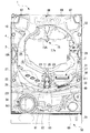
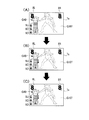
図1に示すように、パチンコ遊技機1は、遊技機枠50を備えている。遊技機枠50は、遊技盤2が取り付けられる遊技盤取付枠51と、遊技盤取付枠51に回転自在に支持される前枠53と、を備える。前枠53は遊技盤取付枠51に対して開閉が可能である。前枠53には、透明のガラス板(図示無し)が取り付けられている。前枠53が閉じられているとき、遊技盤取付枠51に取り付けられた遊技盤2とガラス板とは対面する。よって、パチンコ遊技機1が遊技店に設置されると、当該パチンコ遊技機1の前方にいる遊技者は、図1に示すように、ガラス板を通して、遊技盤2に形成された遊技領域3を視認することができる。なお、ガラス板の代わりに透明な合成樹脂板等を用いてもよい。パチンコ遊技機1の前方から遊技領域3を視認可能であればよい。
As shown in FIG. 1, the
前枠53の前面の右下部には、遊技球を発射させるための回転操作が可能なハンドル60が設けられている。ハンドル60が操作された量(回転角度)が、遊技球を発射させるために遊技球に与えられる力(後述する発射装置112が発射モータ113に駆動させる量)の大きさ(発射強度)に対応付けられている。よって、遊技球は、ハンドル60の回転操作に応じた発射強度で発射される。また、前枠53の前面の下部中央には、ハンドル60に供給される遊技球を貯留する打球供給皿(所謂「上皿」)61と、打球供給皿61に収容しきれない遊技球を貯留する余剰球受皿(所謂「下皿」)62と、が設けられている。
At the lower right of the front surface of the
打球供給皿61の上面には、下方に押下操作可能な演出ボタン63が設けられている。また、前枠53の前面における打球供給皿61の左下には、後方に押下操作可能な演出グリップ64が設けられている。演出グリップ64には、把持可能なグリップ部641が設けられている。グリップ部641を掴んで演出グリップ64全体を後方に押下操作することができる。
An
また、前枠53の前面上部の左側および右側のそれぞれに、音を出力可能なスピーカ67が設けられている。また前枠53の前面上部の中央に、発光可能な枠ランプ66が設けられている。
Further,
次に、遊技盤2などについて説明する。遊技盤2は透明な合成樹脂板で構成されている。遊技盤2の略中央には正面視略円形の開口部10Aが形成された正面視略円形リング状のセンター装飾体10が設けられている。センター装飾体10の下端部で、左右方向中央には、遊技球を真下へ誘導するステージ部11が形成されている。
Next, the
また、遊技盤2の背面側には、画像を表示可能な画像表示装置7が設けられている。そして、遊技盤2と画像表示装置7との間には、作動可能な盤可動体15Aが設けられている。盤可動体15Aは、盤可動装置15を構成している。第1実施形態では、画像表示装置7は、3D液晶ディスプレイで構成されている。盤可動体15Aが待機状態にあるとき(初期位置で待機しているとき)、図1に示すように、その一部分がセンター装飾体10の開口部10Aの上端部から視認可能に保持されている。このとき、画像表示装置7の表示部7aの上端部は盤可動体15Aの視認される部分で覆われている。すなわち、表示部7aは、センター装飾体10の開口部10Aにおける盤可動体15Aに覆われていない部分から視認可能である。盤可動体15Aは、初期位置(待機状態)から、正面視で表示部7aの略中心位置まで下降(下方に移動)し、その位置で停止することができる。この場合、表示部7aは、盤可動体15Aが待機状態のときに比べて多くの領域を盤可動体15Aに覆われる。
Further, an
遊技盤2の前面にはレール部材4が設けられている。そして、遊技盤2の前面には、レール部材4やセンター装飾体10などで囲まれた遊技領域3が形成されている。すなわち、遊技盤2の前面が、レール部材4やセンター装飾体10によって、遊技領域3とそれ以外の領域とに仕切られている。遊技領域3は、ハンドル60の操作によって発射された遊技球が流下可能な領域であり、パチンコ遊技機1で遊技を行うために設けられている。なお、遊技領域3には、不図示の多数の遊技用くぎが突設されている。遊技用くぎは、遊技領域3に進入して遊技領域3を流下する遊技球を、後述する第1始動口20、第2始動口22、一般入賞口27、ゲート28、大入賞口30などに適度に誘導する経路を構成している。
A
遊技領域3におけるステージ部11の下方には、遊技球の入球し易さが変化せずに一定の、すなわち不変の第1始動口20を備える第1始動入賞装置21が設けられている。遊技球の第1始動口20への入賞は、第1特別図柄(以下、「特図1」という)の抽選(後述の特図1関係乱数の取得と判定:以下、「特図1抽選」という)および特図1の可変表示の契機となっている。また、遊技球が第1始動口20へ入賞すると、所定個数(第1実施形態では、4個)の遊技球が賞球として払い出される。なお、ステージ部11の下方に第1始動口20が設けられているため、ステージ部11から下方に落下した遊技球は高確率で第1始動口20に入賞する。
Below the
遊技領域3における第1始動口20の直下には、第2始動口22を備える第2始動入賞装置(所謂「電チュー」)23が設けられている。遊技球の第2始動口22への入賞は、第2特別図柄(以下、「特図2」という)の抽選(後述の特図2関係乱数の取得と判定:以下、「特図2抽選」という)および特図2の可変表示の契機となっている。また、遊技球が第2始動口22へ入賞すると、所定個数(第1実施形態では、4個)の遊技球が賞球として払い出される。
Immediately below the
電チュー23は、開閉可能な開閉部材231を備えている。開閉部材231の作動によって第2始動口22が開閉する。開閉部材231は正面視略正方形の平板からなり、通常は第2始動口22を塞いでいる。開閉部材231は下端を中心に、上端が前方へ倒れるように略90度回転することができる。開閉部材231が回転すると、開閉部材231が遊技領域3に垂直に突出した状態になり、流下する遊技球を受け止めて第2始動口22の中に入球させる。このように、開閉部材231が開状態であるときだけ遊技球の第2始動口22への入球が可能となる。
The
また、遊技領域3における第1始動入賞装置21の左側には、3つの一般入賞口27が左に向かって上昇する斜め方向に並んで設けられている。さらに、遊技領域3における後述する大入賞装置31の右斜め上側には、1つの一般入賞口27が設けられている。遊技球が一般入賞口27へ入賞すると、所定個数(第1実施形態では、3個)の遊技球が賞球として払い出される。
Further, on the left side of the first
また、遊技領域3における大入賞装置31の略上方、言い換えれば、正面視で画像表示装置7の右側には、遊技球が通過可能なゲート28が設けられている。遊技球のゲート28の通過は、電チュー23を開放するか否かを決める普通図柄(以下、「普図」という)の抽選(すなわち普通図柄乱数の取得と判定)および普図の可変表示の契機となっている。
Further, a
また、遊技領域3における電チュー23の右斜め上方、言い換えれば、正面視で画像表示装置7の下方でゲート28の下流域側には、大入賞口30を備えた大入賞装置31が設けられている。大入賞装置31は、開状態と閉状態とをとる開閉部材311を備える。開閉部材311の作動により大入賞口30が開閉する。開閉部材311は正面視略横長矩形状の平板からなり、通常は大入賞口30を塞いでいる。開閉部材311は下端を中心に、上端が前方へ倒れるように略90度回転することができる。開閉部材311が回転すると、開閉部材311が遊技領域3に垂直に突出した状態になり、流下する遊技球を受け止めて大入賞口30の中に入球させる。このように、開閉部材311が開状態であるときだけ遊技球の大入賞口30への入球が可能となる。遊技球が大入賞口30へ入賞すると、所定個数(第1実施形態では、14個)の遊技球が賞球として払い出される。
Further, a
また、遊技領域3における大入賞装置31の直下には、その上面が左斜め下方に形成され、遊技球を第2始動口22へ誘導する誘導ステージ32が設けられている。なお、誘導ステージ32の上面を転動する遊技球は第1始動口20へ入賞することができない。
Further, directly below the
また、遊技領域3の最下部には、遊技領域3へ打ち込まれたもののいずれの入賞口にも入賞しなかった遊技球を遊技領域3の外部へ排出する2つのアウト口29が設けられている。
Further, at the lowermost part of the
ところで、各種の入賞口等が配されている遊技領域3は、左右方向の中央より左側の左遊技領域(第1遊技領域)3Aと、右側の右遊技領域(第2遊技領域)3Bと、に分けることができる。遊技球が左遊技領域3Aを流下するように遊技球を発射させるハンドル60の操作態様を「左打ち」という。一方、遊技球が右遊技領域3Bを流下するように遊技球を発射させるハンドル60の操作態様を「右打ち」という。パチンコ遊技機1において、左打ちにて遊技を発射したときに遊技球が流下する流路を、第1流路といい、右打ちにて遊技を発射したときに遊技球が流下する流路を、第2流路という。第1流路および第2流路は、多数の遊技用くぎによっても構成されている。
By the way, the
第1流路上には、第1始動口20と、3つの一般入賞口27と、が設けられている。よって、遊技者は、左打ちにより第1流路を流下するように遊技球を発射させることで、第1始動口20、または、一般入賞口27への入賞を狙うことができる。一方、第2流路上には、第2始動口22と、ゲート28と、大入賞口30と、1つの一般入賞口27と、が設けられている。よって、遊技者は、右打ちにより第2流路を流下するように遊技球を発射させることで、ゲート28の通過や、第2始動口22、大入賞口30、または、一般入賞口27への入賞を狙うことができる。
A
また、遊技盤2の前面に形成された遊技領域3の上下方向略中央の右隣(遊技領域3以外の部分)には表示器類40が配置されている。図2に示すように、表示器類40には、特図1を可変表示することができる特図1表示器41a、特図2を可変表示することができる特図2表示器41b、及び、普図を可変表示する普図表示器42が含まれている。また、表示器類40には、後述する特図1保留数(U1:特図1表示器41aによる特図1の可変表示が保留されている数)を表示することができる特図1保留表示器43a、後述する特図2保留数(U2:特図2表示器41bによる特図2の可変表示が保留されている数)を表示することができる特図2保留表示器43b、および、後述する普図保留数(G:普図表示器42による普図の可変表示が保留されている数)を表示することができる普図保留表示器44が含まれている。
Further, the
特図1の可変表示は、第1始動口20への遊技球の入賞を契機に特図1抽選が行われると実行される。また、特図2の可変表示は、第2始動口22への遊技球の入賞を契機に特図2抽選が行われると実行される。なお、以下の説明では、特図1および特図2を総称して特図といい、特図1抽選および特図2抽選を総称して特図抽選という。また、特図1表示器41aおよび特図2表示器41bを総称して特図表示器41という。さらに、特図1保留表示器43aおよび特図2保留表示器43bを総称して特図保留表示器43という。
The variable display of the special figure 1 is executed when the special figure 1 lottery is performed when the game ball is won in the
特図の可変表示は、特図抽選の結果を報知する。特図の可変表示では、特図が変動表示したあと停止表示する。停止表示される特図(停止特図、可変表示の表示結果として導出表示される特別図柄)は、特図抽選によって複数種類の特図の中から選択された一つの特図である。停止特図が予め定めた特定の特図(特定の停止態様の特図すなわち大当たり図柄)である場合には、停止表示された特定の特図の種類(つまり当選した大当たりの種別)に応じた開放パターンにて大入賞口30を開放させる大当たり遊技が行われる。
The variable display of the special figure notifies the result of the special figure lottery. In the variable display of the special figure, the special figure is displayed in a variable manner and then stopped. The stop-displayed special figure (stop special figure, special symbol derived and displayed as a display result of variable display) is one special figure selected from a plurality of types of special figures by a special figure lottery. When the stop special figure is a predetermined special figure (special figure of a specific stop mode, that is, a jackpot symbol), it corresponds to the type of the specific special figure that is stopped and displayed (that is, the type of the winning jackpot). A big hit game is performed in which the big winning
特図表示器41は、横並びに配された8個のLEDから構成されており、その点灯態様によって特図抽選の結果に応じた特図を表示する。例えば特図抽選の結果が大当たり(後述の複数種類の大当たりのうちの一つ)である場合には、特図表示器41は、「□□■■□□■■」(□:点灯、■:消灯)というように左から1,2,5,6番目にあるLEDの点灯で構成される大当たり図柄を表示する。また、特図抽選の結果がハズレである場合には、特図表示器41「■■■■■■■□」というように一番右にあるLEDのみの点灯で構成されるハズレ図柄を表示する。なお、特図抽選の結果に対応するLEDの点灯態様は限定されず、適宜に設定することができる。よって、例えば、ハズレ図柄として全てのLEDを消灯させてもよい。
The
また、特図の可変表示において、特図が停止表示される前には所定の変動時間にわたって特図の変動表示がなされる。特図の変動表示の態様は、例えば左から右へ光が繰り返し流れるように各LEDが点灯する態様である。なお、変動表示の態様は、特に限定されず、各LEDが停止表示(特定の態様での点灯表示)されていなければ、全LEDが一斉に点滅するなど適宜に設定してよい。 Further, in the variable display of the special figure, the variable display of the special figure is performed over a predetermined fluctuation time before the special figure is stopped and displayed. The variation display mode of the special figure is, for example, a mode in which each LED is turned on so that light repeatedly flows from left to right. The mode of the variable display is not particularly limited, and if each LED is not stopped and displayed (lighting display in a specific mode), all the LEDs may be set as appropriate, such as blinking all at once.
ところで、パチンコ遊技機1では、遊技球が第1始動口20または第2始動口22へ入賞(入球)すると、特図抽選などを行うための各種乱数(数値情報)が取得されることがある。この各種乱数は、特図保留として特図保留記憶部85(図3参照)に一旦記憶される。なお、以下において、遊技球が第1始動口20へ入賞(入球)したことにより取得された各種乱数のことを「特図1関係乱数」といい、遊技球が第2始動口22へ入賞(入球)したことにより取得された各種乱数のことを「特図2関係乱数」という。ここで、特図1関係乱数は、特図1保留として、特図保留記憶部85の中の特図1保留記憶部85a(図3参照)に記憶される。一方、特図2関係乱数は、特図2保留として、特図保留記憶部85の中の特図2保留記憶部85b(図3参照)に記憶される。特図1保留記憶部85aに記憶可能な特図1保留の数(特図1保留数)および特図2保留記憶部85bに記憶可能な特図2保留の数(特図2保留数)には上限がある。第1実施形態において、特図1保留数および特図2保留数の上限値はそれぞれ4個に設定されている。なお、以下において、特図1保留と特図2保留を総称して「特図保留」といい、特図1保留数と特図2保留数を総称して「特図保留数」という。また、特図1関係乱数と特図2関係乱数とを総称して「特図関係乱数」という。
By the way, in the
パチンコ遊技機1では、遊技球が第1始動口20または第2始動口22へ入賞した後すぐに特図の可変表示が行われない場合、具体的には、特図の可変表示の実行中や大当たり遊技の実行中に入賞があった場合、所定個数を上限として、その入賞に対する特図の可変表示(あるいは、特図抽選の権利)を留保することができる。特図保留記憶部85に記憶された特図保留は、その特図保留に基づく特図の可変表示が可能となったときに消化される。すなわち、特図保留の消化とは、その特図保留に対応する特図関係乱数等を判定して、その判定結果を示すための特図の可変表示を実行することをいう。
In the
そして、特図保留数は、特図保留表示器43に表示される。特図1保留表示器43aと特図2保留表示器43bのそれぞれは、4個のLEDで構成されており、特図保留数の分だけLEDを点灯させることにより特図保留数を表示する。
Then, the number of special figure reservations is displayed on the special
また、普図の可変表示は、普図抽選の結果を報知する。普図の可変表示では、普図が変動表示した後に停止表示する。停止表示される普図(停止普図、可変表示の表示結果として導出表示される普図)は、普図抽選によって複数種類の普図の中から選択された一つの普図である。停止表示された普図が予め定めた特定の普図(所定の停止態様の普図すなわち当たり図柄)である場合には、現在の遊技状態に応じた開放パターンにて第2始動口22(電チュー23)が開放する補助遊技が行われる。 In addition, the variable display of the general map informs the result of the general map lottery. In the variable display of the normal map, the normal map is displayed in a variable manner and then stopped. The stopped-displayed normal map (stop-displayed normal map, the normal map derived and displayed as a display result of the variable display) is one regular map selected from a plurality of types of regular maps by the regular map lottery. When the stop-displayed normal figure is a predetermined specific normal figure (a normal figure in a predetermined stop mode, that is, a winning symbol), the second start port 22 (electricity) has an opening pattern according to the current gaming state. An auxiliary game opened by Chu 23) is performed.
普図表示器42は、例えば2個のLEDから構成されており、その点灯態様によって普図抽選の結果に応じた普図を表示する。普図抽選の結果が当たりである場合には、普図表示器42は、「□□」(□:点灯、■:消灯)というように両LEDの点灯で構成される当たり図柄を表示する。また普図抽選の結果がハズレである場合には、「■□」というように右のLEDのみの点灯で構成されるハズレ図柄を表示する。ハズレ図柄として全てのLEDを消灯させる態様を採用してもよい。なお、普図抽選の結果に対応するLEDの点灯態様は限定されず、適宜に設定することができる。
The
また、普図の変動表示は、普図が停止表示される前には所定の変動時間にわたって行われる。普図の変動表示の態様は、第1実施形態では、両LEDが交互に点灯するという態様である。なお、普図の変動表示の態様は、特に限定されず、各LEDが停止表示(特定の態様での点灯表示)されていなければ、全LEDが一斉に点滅するなど適宜に設定してもよい。 Further, the fluctuation display of the normal map is performed for a predetermined fluctuation time before the normal map is stopped and displayed. In the first embodiment, the variation display of the normal diagram is such that both LEDs are turned on alternately. The mode of the variable display in the normal drawing is not particularly limited, and if each LED is not stopped and displayed (lighting display in a specific mode), all the LEDs may be appropriately set such as blinking all at once. ..
パチンコ遊技機1では、遊技球がゲート28を通過すると、普図抽選を行うための普通図柄乱数(数値情報)が取得されることがある。この乱数は、普図保留として普図保留記憶部86(図3参照)に一旦記憶される。普図保留記憶部86に記憶可能な普図保留の数(普図保留数)には上限がある。第1実施形態において、普図保留数の上限値は4個に設定されている。なお、以下において、遊技球がゲート28を通過することにより取得された普通図柄乱数のことを「普図関係乱数」ともいう。
In the
また、パチンコ遊技機1では、遊技球がゲート28を通過することに基づく普図の可変表示をその通過後すぐに行えない場合、詳細には、普図の可変表示の実行中や補助遊技の実行中に遊技球がゲート28を通過した場合、所定個数を上限として、その通過に対する普図の可変表示(あるいは、普図抽選の権利)を留保することができる。普図保留記憶部86に記憶された普図保留は、その普図保留に基づく普図の可変表示が可能となったときに消化される。普図保留の消化とは、その普図保留に対応する普通図柄乱数を判定して、その判定結果を示すための普図の可変表示を実行することをいう。
Further, in the
そして、このような普図保留数は、普図保留表示器44に表示される。具体的には普図保留表示器44はそれぞれ、例えば4個のLEDで構成されており、普図保留数の分だけLEDを点灯させることにより普図保留数を表示する。
Then, such a number of reserved figures is displayed on the reserved
2.遊技機の電気的構成
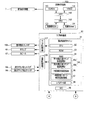
次に、図3および図4に基づいて、パチンコ遊技機1における電気的な構成を説明する。図3および図4に示すように、パチンコ遊技機1は、特図抽選、特図の可変表示、大当たり遊技、後述する遊技状態の設定、普図抽選、普図の可変表示、補助遊技などの遊技利益に関する制御(遊技の進行)を行う主制御基板80、主制御基板80による遊技の進行に応じた遊技演出(変動演出、保留演出、大当たり遊技演出)、客待ち演出、演出ボタン63や演出グリップ64の操作が有効な期間(操作有効期間)において操作を促す操作促進演出などの演出に関する制御を行うサブ制御基板90、および、遊技球の払い出しに関する制御などを行う払出制御基板110等を遊技盤2の画像表示装置7よりさらに背面側に備えている。主制御基板80は、遊技の制御を行う遊技制御部と位置づけ、サブ制御基板90は、後述する画像制御基板100、ランプ制御回路107、および音声制御回路106とともに、演出の制御を行う演出制御部と位置づけることができる。なお、演出制御部は、少なくともサブ制御基板90を備え、演出手段(画像表示装置7、盤可動装置15、枠ランプ66、および、スピーカ67等)を用いた遊技演出、客待ち演出、および操作促進演出を制御可能であればよい。
2. Electrical configuration of the gaming machine Next, the electrical configuration of the
また、パチンコ遊技機1は、電源基板160を備えている。電源基板160は、主制御基板80、サブ制御基板90、及び払出制御基板110に対して電力を供給するとともに、これらの基板を介してその他の機器に対して必要な電力を供給する。電源基板160には、バックアップ電源回路161が設けられている。バックアップ電源回路161は、パチンコ遊技機1に対して電力が供給されていない場合に、後述する主制御基板80のRAM84やサブ制御基板90のRAM94に対して電力を供給する。従って、主制御基板80のRAM84やサブ制御基板90のRAM94に記憶されている情報は、パチンコ遊技機1の電断時であっても保持される。また、電源基板160には、電源スイッチ165が接続されている。電源スイッチ165のON/OFF操作により、電源の投入/遮断が切り換えられる。なお、主制御基板80のRAM84に対するバックアップ電源回路を主制御基板80に設けたり、サブ制御基板90のRAM94に対するバックアップ電源回路をサブ制御基板90に設けたりしてもよい。
Further, the
図3に示すように、主制御基板80には、プログラムに従ってパチンコ遊技機1の遊技の進行を制御する遊技制御用ワンチップマイコン(以下「遊技制御用マイコン」)81が実装されている。遊技制御用マイコン81には、遊技の進行を制御するためのプログラムやテーブル等を記憶したROM83、ワークメモリとして使用されるRAM84、ROM83に記憶されたプログラムを実行するCPU82、データや信号の入出力を行うためのI/Oポート部(入出力回路)88が含まれている。
As shown in FIG. 3, a game control one-chip microcomputer (hereinafter, “game control microcomputer”) 81 that controls the progress of the game of the
ROM83には、後述する主制御メイン処理やメイン側タイマ割り込み処理などを行うためのプログラムが格納されている。また、ROM83には、後述する大当たり判定テーブル、大当たり図柄種別判定テーブル、リーチ判定テーブル、特図変動パターン判定テーブル、大当たり遊技制御テーブル、当たり判定テーブル、普図変動パターン判定テーブル、電チュー開放パターンテーブルなどが格納されている。なお、ROM83は外付けであってもよい。また、RAM84には、前述した特図保留記憶部85や普図保留記憶部86などが設けられている。
The
また、主制御基板80には、RAM84に記憶されている情報をCPU82にクリアさせるためのRAMクリアスイッチ89が実装されている。
Further, the
主制御基板80には、所定の中継基板(図示なし)を介して各種センサ類やソレノイド類が接続されている。そのため、主制御基板80には、各種センサ類が出力した信号が入力する。また、主制御基板80は、各種ソレノイド類に信号を出力する。
Various sensors and solenoids are connected to the
主制御基板80に接続されている各種センサ類には、第1始動口センサ20a、第2始動口センサ22a、ゲートセンサ28a、大入賞口センサ30a、および、一般入賞口センサ27aが含まれている。
Various sensors connected to the
第1始動口センサ20aは、第1始動口20に入賞した遊技球を検知する。第2始動口センサ22aは、第2始動口22に入賞した遊技球を検知する。ゲートセンサ28aは、ゲート28に設けられており、ゲート28を通過した遊技球を検知する。大入賞口センサ30aは、大入賞口30に入賞した遊技球を検知する。一般入賞口センサ27aは、一般入賞口27に入賞した遊技球を検知する。各センサは、遊技球を検知すると、その検知内容に応じた信号を主制御基板80に出力する。
The first starting port sensor 20a detects a game ball that has won a prize in the
また、主制御基板80に接続されている各種ソレノイド類には、電チューソレノイド23B、および、大入賞口ソレノイド31Bが含まれている。電チューソレノイド23Bは、電チュー23の開閉部材231を駆動する。大入賞口ソレノイド31Bは、大入賞装置31の開閉部材311を駆動する。
Further, various solenoids connected to the
さらに主制御基板80には、表示器類40(特図表示器41、普図表示器42、特図保留表示器43、および普図保留表示器44)が接続されている。これらの表示器類40の表示制御は、遊技制御用マイコン81によりなされる。
Further, indicators 40 (
また主制御基板80は、払出制御基板110に各種コマンドを送信するとともに、払い出し監視のために払出制御基板110から信号を受信する。払出制御基板110には、賞球払出装置120、貸球払出装置130およびカードユニット135(パチンコ遊技機1に隣接して設置され、挿入されているプリペイドカード等の情報に基づいて球貸しを可能にするもの)が接続されているとともに、発射制御回路111を介して発射装置112が接続されている。なお、発射装置112には、ハンドル60(図1参照)が含まれる。
Further, the
払出制御基板110は、遊技制御用マイコン81からの信号や、接続されたカードユニット135からの信号に基づいて、賞球払出装置120の賞球モータ121を駆動して賞球の払い出しを行ったり、貸球払出装置130の貸球モータ131を駆動して貸球の払い出しを行ったりする。払い出される賞球は、その計数のための賞球センサ122により検知される。また払い出される貸球は、その計数のための貸球センサ132により検知される。
The
また、ハンドル60には、遊技者などの人のハンドル60への接触を検知可能なタッチスイッチ114が設けられている。遊技者によるハンドル60(図1参照)の操作があった場合には、タッチスイッチ114が遊技者のハンドル60への接触を検知し、検知信号を払出制御基板110に出力する。また、ハンドル60には、ハンドル60の回転角度(操作量)を検出可能な発射ボリュームつまみ115が接続されている。発射装置112は、発射ボリュームつまみ115が検出したハンドル60の回転角度に応じた強さで遊技球が発射されるよう発射モータ113を駆動させる。なお、パチンコ遊技機1においては、ハンドル60への回転操作が維持されている状態では、約0.6秒毎に1球の遊技球が発射されるようになっている。
Further, the
また主制御基板80は、遊技の進行に応じて、サブ制御基板90に対し、遊技に関する情報を含んだ各種コマンドを送信する。サブ制御基板90は、主制御基板80から送られる各種コマンドに基づいて、主制御基板80による遊技の進行状況(遊技の制御内容)を把握することができる。なお、主制御基板80とサブ制御基板90との接続は、主制御基板80からサブ制御基板90への信号の送信のみが可能な単方向通信接続となっている。すなわち、主制御基板80とサブ制御基板90との間には、通信方向規制手段としての図示しない単方向性回路(例えばダイオードを用いた回路)が介在している。
Further, the
図4に示すように、サブ制御基板90には、プログラムに従ってパチンコ遊技機1の演出を制御する演出制御用ワンチップマイコン(以下「演出制御用マイコン」)91が実装されている。演出制御用マイコン91には、主制御基板80による遊技の進行に伴って演出を制御するためのプログラム等を記憶したROM93、ワークメモリとして使用されるRAM94、ROM93に記憶されたプログラムを実行するCPU92、データや信号の入出力を行うためのI/Oポート部(入出力回路)98が含まれている。
As shown in FIG. 4, a one-chip microcomputer for effect control (hereinafter, “microcomputer for effect control”) 91 that controls the effect of the
また、ROM93には、後述するサブ制御メイン処理、受信割り込み処理、1msタイマ割り込み処理、および、10msタイマ割り込み処理などを行うためのプログラムが格納されている。また、ROM93には、後述する停止図柄判定テーブル、ゲージ最大値判定テーブル、演出モード判定テーブル、ゲージ上昇判定テーブル、カットイン予告実行判定テーブル、および、ゲージ最大値到達演出実行判定テーブルなどが格納されている。なお、ROM93は外付けであってもよい。
Further, the
また、サブ制御基板90には、リアルタイムクロック(RTC)99が実装されている。RTC99は、現時点の日時(日付及び時刻)を計測する。RTC99は、パチンコ遊技機1に、所定の島電源供給装置(図示なし)から電力が供給されているときにはその電力によって動作し、島電源供給装置から電力が供給されていないときには、電源基板160が備えるバックアップ電源回路161から供給される電力によって動作する。このため、RTC99は、パチンコ遊技機1の電源が投入されていないときにも現在の日時を計測することが可能である。なお、RTC99に対するバックアップ電源回路をサブ制御基板90に設けてもよい。バックアップ電源回路には、コンデンサや内臓電池(ボタン電池等)を含む回路を採用することができる。
A real-time clock (RTC) 99 is mounted on the
サブ制御基板90には、画像制御基板100が接続されている。サブ制御基板90の演出制御用マイコン91は、主制御基板80から受信したコマンドに基づいて、すなわち、主制御基板80による遊技の進行に応じて、画像制御基板100のCPU102に画像表示装置7の表示制御を行わせる。なお、サブ制御基板90と画像制御基板100との接続は、サブ制御基板90から画像制御基板100への信号の送信と、画像制御基板100からサブ制御基板90への信号の送信の双方が可能な双方向通信接続となっている。
An
画像制御基板100は、画像制御のためのプログラム等を記憶した制御用ROM103、ワークメモリとして使用される制御用RAM104、及び、制御用ROM103に記憶されたプログラムを実行するCPU102を備えている。また、画像制御基板100は、画像表示装置7に表示される画像のデータを記憶したCGROM143、CGROM143に記憶されている画像データの展開等に使用されるVRAM144、及び、VDP(Video Display Processor)142を備えている。勿論、これらの電子部品の全部又は一部がワンチップで構成されていてもよい。CGROM143には、例えば、画像表示装置7に表示される画像を表示するための画像データ(静止画データや動画データ、具体的にはキャラクタ、アイテム、図形、文字、数字および記号等(演出図柄を含む)や背景画像等の画像データ)が格納されている。
The
VDP142は、演出制御用マイコン91からの指令に基づきCPU102によって作成されるディスプレイリストに従って、CGROM143から画像データを読み出してVRAM144内の展開領域に展開する。そして、展開した画像データを適宜合成してVRAM144内のフレームバッファに画像を描画する。そしてフレームバッファに描画した画像をRGB信号として画像表示装置7に出力する。これにより、種々の演出画像が表示部7aに表示される。
The
なお、ディスプレイリストは、フレーム単位で描画の実行を指示するためのコマンド群で構成されている。ディスプレイリストには、描画する画像の種類、画像を描画する位置、表示の優先順位、表示倍率、画像の透過率等の種々のパラメータの情報が含まれている。 The display list is composed of a group of commands for instructing the execution of drawing on a frame-by-frame basis. The display list contains information on various parameters such as the type of image to be drawn, the position where the image is drawn, the display priority, the display magnification, and the transmittance of the image.
演出制御用マイコン91は、主制御基板80から受信したコマンドに基づいて、すなわち、主制御基板80による遊技の進行に応じて、音声制御回路106を介してスピーカ67から音声、楽曲、効果音等を出力する。
The
スピーカ67から出力する音声等の音声データは、サブ制御基板90のROM93に格納されている。なお、音声制御回路106を、基板にしてCPUを実装してもよい。この場合、そのCPUに音声制御を実行させてもよい。さらにこの場合、基板にROMを実装し、そのROMに音声データを格納してもよい。また、スピーカ67を画像制御基板100に接続し、画像制御基板100のCPU102に音声制御を実行させてもよい。さらにこの場合、画像制御基板100の制御用ROM103に音声データを格納してもよい。
Audio data such as audio output from the
また、サブ制御基板90には、所定の中継基板(図示なし)を介して、入力部となる各種スイッチ類や駆動源となる各種ソレノイド類やモータ類が接続されている。サブ制御基板90には、各種スイッチ類が出力した信号が入力する。また、サブ制御基板90は、各種ソレノイド類やモータ類に信号を出力する。
Further, various switches serving as input units and various solenoids and motors serving as drive sources are connected to the
サブ制御基板90に接続されている各種スイッチ類には、演出ボタン検出スイッチ63a、および、演出グリップ検出スイッチ64aが含まれている。
Various switches connected to the
演出ボタン検出スイッチ63aは、演出ボタン63が押下操作されたことを検出する。演出グリップ検出スイッチ64aは、演出グリップ64が押下操作されたことを検出する。各検出スイッチは、操作されたことを検出すると、その検出内容に応じた信号をサブ制御基板90に出力する。
The effect
サブ制御基板90に接続された各種ソレノイド類には、盤可動体ソレノイド15Bが含まれている。盤可動体ソレノイド15Bは、盤可動体15Aを駆動して作動させる。詳細には演出制御用マイコン91は、盤可動体15Aの動作態様を決める動作パターンデータを作成し、ランプ制御回路107を介して、盤可動体15Aの動作を制御する。なお、盤可動体15Aと盤可動体ソレノイド15Bとによって盤可動装置15が構成される。
Various solenoids connected to the
また、演出制御用マイコン91は、主制御基板80から受信したコマンドなどに基づいて、ランプ制御回路107を介して枠ランプ66等の点灯制御を行う。詳細には演出制御用マイコン91は、枠ランプ66の発光態様を決める発光パターンデータ(点灯/消灯や発光色等を決めるデータ、ランプデータともいう)を作成し、発光パターンデータに従って枠ランプ66の発光を制御する。なお、発光パターンデータの作成にはサブ制御基板90のROM93に格納されているデータを用いる。
Further, the
なお、ランプ制御回路107を基板にしてCPUを実装してもよい。この場合、そのCPUに、枠ランプ66等の点灯制御、および、盤可動体15Aの動作制御を実行させてもよい。さらにこの場合、基板にROMを実装して、そのROMに発光パターンや動作パターンに関するデータを格納してもよい。
The CPU may be mounted on the
3.主制御基板80による遊技の説明
次に、主制御基板80により行われる遊技について説明する。発射された遊技球が第1始動口20に入賞すると、特図1保留数(U1)が4未満であることを条件に、特図1抽選を行う。特図1抽選が行われると、特図1表示器41aにおいて、特図1の可変表示(変動表示を行った後に停止表示)を行って、特図1抽選の結果を報知する。ここで、停止表示される特図1には、大当たり図柄とハズレ図柄とがある。すなわち、特図1抽選の結果には大当たりとハズレがある。大当たり図柄が停止表示されると大当たり遊技が実行され、新たな遊技状態が設定されて、当該入賞に基づく遊技が終了する。一方、ハズレ図柄が停止表示されると大当たり遊技が行われず、当該入賞に基づく遊技が終了する。
3. 3. Description of the game by the
同様に、発射された遊技球が第2始動口22に入賞すると、特図2保留数(U2)が4未満であることを条件に、特図2抽選を行う。特図2抽選が行われると、特図2表示器41bにおいて、特図2の可変表示(変動表示を行った後に停止表示)を行って、特図2抽選の結果を報知する。ここで、停止表示される特図2には、大当たり図柄とハズレ図柄とがある。すなわち、特図2抽選の結果には、大当たりとハズレがある。大当たり図柄が停止表示されると大当たり遊技が実行され、新たな遊技状態が設定されて、当該入賞に基づく遊技が終了する。一方、ハズレ図柄が停止表示されると大当たり遊技が行われず、当該入賞に基づく遊技が終了する。
Similarly, when the launched game ball wins the
なお、以下において、特図1保留数(U1)が4未満であるときに第1始動口20に遊技球が入賞することを「第1始動条件の成立」といい、特図2保留数(U2)が4未満であるときに第2始動口22に遊技球が入賞することを「第2始動条件の成立」という。また、「第1始動条件の成立」と「第2始動条件の成立」をまとめて「始動条件の成立」と総称する。
In the following, when the number of reserved special figures 1 (U1) is less than 4, the winning of the game ball in the
主制御基板80は、このような一連の遊技(特図抽選、特図の可変表示、大当たり遊技、遊技状態の設定)を行うにあたり、始動条件の成立により、特図関係乱数を取得し、当該乱数について種々の判定を行う。取得する特図関係乱数には、図5(A)に示すように、特別図柄乱数、大当たり図柄種別乱数、リーチ乱数および変動パターン乱数がある。特別図柄乱数は大当たり判定を行うための乱数(数値情報)である。大当たり図柄種別乱数は大当たり図柄種別判定を行うための乱数(数値情報)である。リーチ乱数はリーチ判定を行うための乱数(数値情報)である。変動パターン乱数は特別図柄の変動パターン判定を行うための乱数(数値情報)である。各乱数には、適宜に範囲が設けられている。具体的に、特別図柄乱数の範囲は、0〜65535である。大当たり図柄種別乱数の範囲は、0〜199である。リーチ乱数の範囲は、0〜255である。変動パターン乱数の範囲は、0〜99である。
In performing such a series of games (special figure lottery, variable display of special figures, big hit game, setting of game state), the
次に、特図関係乱数を用いて行われる各判定について説明する。最初に、大当たり判定について説明する。大当たり判定は、図6(A)に示す大当たり判定テーブルを用いて、大当たりか否か(大当たり遊技を実行するか否か)を決定するための判定である。大当たり判定テーブルは、遊技状態(通常確率状態/高確率状態)に関連付けられている。すなわち、大当たり判定テーブルには、通常確率状態のときに用いられる大当たり判定テーブル(通常確率大当たり判定テーブル)と高確率状態のときに用いられる大当たり判定テーブル(高確率大当たり判定テーブル)とがある。通常確率状態と高確率状態についての詳細は後述するが、通常確率状態は大当たり判定で大当たりと判定される確率が相対的に低く設定された遊技状態である。一方、高確率状態は大当たり判定で大当たりと判定される確率が相対的に高く設定された遊技状態である。 Next, each determination performed using the special figure-related random numbers will be described. First, the jackpot determination will be described. The jackpot determination is a determination for determining whether or not a jackpot is a jackpot (whether or not a jackpot game is executed) using the jackpot determination table shown in FIG. 6A. The jackpot determination table is associated with a gaming state (normal probability state / high probability state). That is, the jackpot determination table includes a jackpot determination table (normal probability jackpot determination table) used in the normal probability state and a jackpot determination table (high probability jackpot determination table) used in the high probability state. The details of the normal probability state and the high probability state will be described later, but the normal probability state is a gaming state in which the probability of being determined as a jackpot in the jackpot determination is set to be relatively low. On the other hand, the high probability state is a gaming state in which the probability of being determined as a jackpot in the jackpot determination is set to be relatively high.
各大当たり判定テーブルでは、大当たり判定の結果である大当たりとハズレに、特別図柄乱数の判定値(特別図柄乱数判定値)が振り分けられている。主制御基板80は、取得した特別図柄乱数を大当たり判定テーブルに照合して、大当たりかハズレかを判定する。図6(A)に示すように、高確率状態で用いられる大当たり判定テーブルの方が、通常確率状態で用いられる大当たり判定テーブルよりも、大当たりと判定される特別図柄乱数判定値が多く設定されている。大当たり判定の結果が大当たりであると、特別図柄の可変表示で大当たり図柄が停止表示される。一方、大当たり判定の結果がハズレであると、特別図柄の可変表示でハズレ図柄が停止表示される。
In each jackpot determination table, the determination value of the special symbol random number (special symbol random number determination value) is assigned to the jackpot and the loss which are the results of the jackpot determination. The
次に、大当たり図柄種別判定について説明する。大当たり図柄種別判定は、大当たり判定の結果が大当たりである場合に、図6(B)〜図6(C)に示す大当たり図柄種別判定テーブルを用いて大当たり図柄の種別を決定するための判定である。大当たり図柄の種別には、大当たりの内容、換言すれば、遊技者に付与される遊技特典などで構成される大当たりの構成要素が対応付けられている。大当たり図柄種別に対応付けられた大当たりの内容(大当たりの構成要素)については後述する。 Next, the jackpot symbol type determination will be described. The jackpot symbol type determination is a determination for determining the jackpot symbol type using the jackpot symbol type determination tables shown in FIGS. 6 (B) to 6 (C) when the result of the jackpot determination is a jackpot. .. The type of jackpot symbol is associated with a jackpot component composed of the contents of the jackpot, in other words, a game privilege given to the player. The contents of the jackpot (components of the jackpot) associated with the jackpot symbol type will be described later.
大当たり図柄種別判定テーブルは、可変表示される特別図柄の種別(特図1/特図2)、言い換えれば、当該大当たり図柄種別判定が起因する(当該大当たり図柄種別判定を発生させた)入賞が行われた始動口の種別(第1始動口20/第2始動口22)に関連付けられている。すなわち、大当たり図柄種別判定テーブルには、特図1の可変表示を行うときに用いられる大当たり図柄種別判定テーブル(第1大当たり図柄種別判定テーブル:図6(B))と特図2の可変表示を行うときに用いられる大当たり図柄種別判定テーブル(第2大当たり図柄種別判定テーブル:図6(C))とがある。そして、第1大当たり図柄種別判定テーブルおよび第2大当たり図柄種別判定テーブルのそれぞれはさらに、遊技状態(非時短状態/時短状態)に関連付けられている。すなわち、第1大当たり図柄種別判定テーブルには、非時短状態のときに用いられる第1大当たり図柄種別判定テーブルと時短状態のときに用いられる第1大当たり図柄種別判定テーブルとがある。また、第2大当たり図柄種別判定テーブルには、非時短状態のときに用いられる第2大当たり図柄種別判定テーブルと時短状態のときに用いられる第2大当たり図柄種別判定テーブルとがある。なお、非時短状態と時短状態については後述する。
In the jackpot symbol type determination table, the type of special symbol that is variably displayed (special diagram 1 / special diagram 2), in other words, the winning of the jackpot symbol type determination (which caused the jackpot symbol type determination) is performed. It is associated with the type of starting port (first starting
4つの各大当たり図柄種別判定テーブルでは、大当たり図柄種別判定の結果である大当たり図柄の種別に、大当たり図柄種別乱数の判定値(大当たり図柄種別乱数判定値)が振り分けられている。よって、主制御基板80は、取得した大当たり図柄種別乱数を大当たり図柄種別判定テーブルに照合して、大当たり図柄の種別を判定する。図6(B)に示すように、第1始動口20に入賞した場合の(特図1に係る)大当たり図柄として、大当たり図柄A01〜大当たり図柄A04の4種類の大当たり図柄が設けられている。一方、図6(C)に示すように、第2始動口22に入賞した場合の(特図2に係る)大当たり図柄として、大当たり図柄B01〜大当たり図柄B09の9種類の大当たり図柄が設けられている。そして、第1大当たり図柄種別判定テーブルおよび第2大当たり図柄種別判定テーブルでは、大当たり図柄種別乱数判定値が各種大当たり図柄に適宜に振り分けられている。
In each of the four jackpot symbol type determination tables, the determination value of the jackpot symbol type random number (the jackpot symbol type random number determination value) is assigned to the type of the jackpot symbol which is the result of the jackpot symbol type determination. Therefore, the
なお、大当たりの当選確率および大当たり図柄種別の振分率(%)は図6(B)〜図6(C)に限られず、適宜に設定することができる。また、大当たり図柄の種別は、図6(B)〜図6(C)に示す14種類の大当たり図柄に限らず、適宜に設定することができる。例えば、第1大当たり図柄種別判定テーブルにおいて、4種類より多い又は少ない種類の大当たり図柄が大当たり図柄種別乱数判定値に対応付けられていても良い。また、第2大当たり図柄種別判定テーブルにおいて、9種類より多い又は少ない種類の大当たり図柄が大当たり図柄種別乱数判定値に対応付けられていても良い。 The jackpot winning probability and the jackpot symbol type distribution rate (%) are not limited to FIGS. 6 (B) to 6 (C) and can be set as appropriate. Further, the type of the jackpot symbol is not limited to the 14 types of jackpot symbols shown in FIGS. 6 (B) to 6 (C), and can be appropriately set. For example, in the first jackpot symbol type determination table, more or less than four types of jackpot symbols may be associated with the jackpot symbol type random number determination value. Further, in the second jackpot symbol type determination table, more or less than nine types of jackpot symbols may be associated with the jackpot symbol type random number determination value.
次に、リーチ判定について説明する。リーチ判定は、大当たり判定の結果がハズレである場合に、図6(D)に示すリーチ判定テーブルを用いてリーチを発生させるか否かを決定するための判定である。ここで、リーチについて説明するために、リーチの前提となる変動演出について説明する。 Next, the reach determination will be described. The reach determination is a determination for determining whether or not to generate a reach using the reach determination table shown in FIG. 6D when the result of the jackpot determination is a loss. Here, in order to explain the reach, the fluctuation effect that is the premise of the reach will be described.
特図の可変表示が行われると、当該特図の可変表示に応じて、変動演出が行われる。変動演出は、画像表示装置7、盤可動装置15、演出ボタン63、演出グリップ64、枠ランプ66、および、スピーカ67などの様々な演出装置を用いて行われる。変動演出として、画像表示装置7の表示部7aでは、当該特図の可変表示に同期した演出図柄の可変表示が行われる。すなわち、特図の変動表示に伴って演出図柄の変動表示が行われ、特図の変動停止(停止表示)に伴って、演出図柄の変動停止(停止表示)が行われる。なお、演出図柄を変動表示する演出を演出図柄変動演出ともいう。演出図柄変動演出は「変動演出」の一部を構成している。なお、演出図柄には、通常の演出図柄である通常演出図柄と、基本的には通常演出図柄よりも小さい小演出図柄と、がある。
When the variable display of the special figure is performed, the variable effect is performed according to the variable display of the special figure. The variable effect is performed using various effect devices such as an
通常演出図柄は、例えば、表示部7aが「左」「中」「右」の3つの図柄表示エリアに分けられ、左の図柄表示エリアに表示される左演出図柄8Lと、中の図柄表示エリアに表示される中演出図柄8Cと、右の図柄表示エリアに表示される右演出図柄8Rとで構成される(図17など参照)。なお、以下において、左演出図柄8L、中演出図柄8Cおよび右演出図柄8Rを総称する場合に「演出図柄8L、8C、8R」という場合がある。
In the normal effect symbol, for example, the
演出図柄8L、8C、8Rはそれぞれ、例えば「1」〜「8」までの数字などで構成される。そして、通常演出図柄の変動表示においては、演出図柄8L、8C、8Rが表示部7aの上から下にスクロールして、表示部7a内に表示される(視認される)数字が次々に入れ替わる。なお、通常演出図柄の変動表示の態様としては、上下方向にスクロールする態様に限られず、左右方向(例えば、右から左)にスクロールする態様など他の態様であってもよい。また、スクロール表示ではなく所定の定位置で通常演出図柄を構成する数字が次々に入れ替わる(例えば、その定位置で自転する)態様であってもよい。また、変動演出では、通常演出図柄のほか、小演出図柄や背景画像やキャラクタ画像などの通常演出図柄以外の演出画像も表示される。
Each of the
そして、特図が停止表示されるときに、演出図柄8L、8C、8Rが所定の配列(組み合わせ)で停止表示される。すなわち、変動表示において表示部7aで次々に入れ替わっていた様々な数字が1つに特定される。このとき、停止表示した(特定された)演出図柄8L、8C、8Rの組み合わせによって、特図表示器41にて停止表示される特図(可変表示の結果、つまりは特別図柄抽選の結果)が、わかりやすく表示される。これにより、遊技者による遊技の進行状況の把握が容易となる。つまり遊技者は、一般的には特図抽選の結果を特図1表示器41aや特図2表示器41bにより把握するのではなく、画像表示装置7の表示部7aにて把握する。
Then, when the special figure is stopped and displayed, the
そして、リーチとは、変動演出において、演出図柄8L、8C、8Rを用いて遊技者に大当たりを期待させるための演出である。具体的に、リーチは、演出図柄8L、8C、8Rのうちでスクロール表示されている通常演出図柄が残り一つとなっている状態であって、スクロール表示されている通常演出図柄がどの図柄で停止表示されるか次第で大当たり当選を示す演出図柄の組み合わせとなる状態(例えば「5↓5」の状態)のことである(図16(D)参照)。なお、リーチにおいてスクロール表示されていない通常演出図柄は、表示部7a内の所定位置で仮停止している。仮停止とは、所定の通常演出図柄が略所定位置で留まり(所定の演出図柄が表示部7a内に表示され続け)、すなわち、異なる通常演出図柄に入れ替わることはないものの、微小な変動(例えば、多少の上下方向の往復運動の繰り返し、また、多少の揺動の繰り返し、また、拡大と縮小の繰り返しなど)のことである。なお、仮停止の態様はこれらに限られない。
The reach is an effect for making the player expect a big hit by using the
リーチ判定テーブルは、遊技状態(非時短状態/時短状態)に関連付けられている。すなわち、リーチ判定テーブルには、非時短状態のときに用いられるリーチ判定テーブル(非時短リーチ判定テーブル)と時短状態のときに用いられるリーチ判定テーブル(時短リーチ判定テーブル)とがある。非時短状態と時短状態についての詳細は後述するが、非時短状態と時短状態は、特別図柄の変動表示に要する時間(変動表示開始時から表示結果の導出表示時までの時間:特図変動時間)に関する遊技状態であり、時短状態では、非時短状態よりも特図変動時間が短くなり易い。 The reach determination table is associated with the gaming state (non-time saving state / time saving state). That is, the reach determination table includes a reach determination table (non-time reduction reach determination table) used in the non-time reduction state and a reach determination table (time reduction reach determination table) used in the time reduction state. The details of the non-time saving state and the time saving state will be described later, but the non-time saving state and the time saving state are the time required for the variable display of the special symbol (the time from the start of the variable display to the derivation display of the display result: the special figure variable time). ), And in the time-saving state, the special figure fluctuation time tends to be shorter than in the non-time-saving state.
各リーチ判定テーブルでは、リーチ判定の結果である「リーチ有り(リーチを発生させる)」と「リーチ無し(リーチを発生させない)」に、リーチ乱数の判定値(リーチ乱数判定値)が振り分けられている。よって、主制御基板80は、取得したリーチ乱数をリーチ判定テーブルに照合して、リーチ有りかリーチ無しか(リーチを発生させる否か)を判定する。図6(D)に示すように、非時短状態で用いられるリーチ判定テーブルの方が、時短状態で用いられるリーチ判定テーブルよりも、「リーチ有り(リーチを発生させる)」と判定されるリーチ乱数判定値が多く振り分けられている。リーチ判定の結果が「リーチ有り(リーチを発生させる)」であると、基本的には変動演出でリーチが発生する。一方、リーチ判定の結果が「リーチ無し(リーチを発生させない)」であると、変動演出でリーチが発生しない。すなわち、リーチ判定の結果が「リーチ無し(リーチを発生させない)」であると、変動演出において、通常演出図柄の変動表示が開始した後、当該変動表示中の通常演出図柄に特別なアクションが発生することなく通常演出図柄の変動表示が終了して通常演出図柄の停止表示が行われる。なお、以下において、大当たり判定の結果が「ハズレ」であることを前提に行われるリーチ判定の結果「リーチ有り(リーチを発生させる)」のことを「リーチ有りハズレ」といい、「リーチ無し(リーチを発生させない)」のことを「リーチ無しハズレ」ということもある。
In each reach judgment table, the judgment value of the reach random number (reach random number judgment value) is divided into "with reach (generate reach)" and "without reach (do not generate reach)" which are the results of reach judgment. There is. Therefore, the
一方、小演出図柄は、例えば、表示部7aの左下の狭い領域を「上」「中」「下」の3つの図柄表示エリアに分け、上の図柄表示エリアに表示される上小図柄9Uと、中の図柄表示エリアに表示される中小図柄9Cと、下の図柄表示エリアに表示される下小図柄9Dと、で構成される(図17など参照)。なお、以下において、上小図柄9U、中小図柄9Cおよび下小図柄9Dを総称する場合に「小図柄9U、9C、9D」という場合がある。
On the other hand, in the small effect symbol, for example, the narrow area at the lower left of the
小図柄9U、9C、9Dは、特図変動表示の開始に伴って変動表示する。すなわち、演出図柄8L、8C、8Rの変動表示と小図柄9U、9C、9Dの変動表示が同時に開始される。小図柄9U、9C、9Dはそれぞれ、例えば「1」〜「8」までの数字などで構成される。そして、小演出図柄の変動表示においては、小図柄9U、9C、9Dのそれぞれがその場で異なる数字に次々と入れ替われる。よって、特図変動表示が行われている間、通常演出図柄の変動表示と小演出図柄の変動表示が行われているが、その態様は演出図柄の種類によって異なっている。そして、小図柄9U、9C、9Dは、特図変動表示の停止に伴って停止する。すなわち、演出図柄8L、8C、8Rの停止表示と小図柄9U、9C、9Dの停止表示とが同時に開始される。演出図柄8L、8C、8Rの停止表示と小図柄9U、9C、9Dの停止表示とは、基本的に同じ数字の組み合わせ(停止表示態様)で行われる。なお、詳細は後述するが演出図柄8L、8C、8Rは完全に停止表示される前に、仮停止表示されるが、小図柄9U、9C、9Dについては仮停止表示が行われない。また、演出図柄8L、8C、8Rがリーチ状態のとき、小図柄9U、9C、9Dはリーチ状態になっておらず、3つの小図柄9U、9C、9Dが変動表示している。
The
次に、特別図柄の変動パターン判定について説明する。特別図柄の変動パターン判定(特図変動パターン判定)は、大当たり判定の結果が大当たりおよびハズレの何れの場合にも、図7〜図8に示す特別図柄の変動パターン判定テーブル(特図変動パターン判定テーブル)を用いて、特別図柄の変動表示の変動パターン(特図変動パターン)を決定するための判定である。特図変動パターンとは、特図変動時間や変動演出の演出内容などに関する所定事項を識別するための識別情報である。なお、特図変動パターンには、特図変動時間や変動演出の演出フロー(演出内容)の他、大当たり判定の結果とリーチ判定の結果に関する情報も含まれている。 Next, the fluctuation pattern determination of the special symbol will be described. In the special symbol variation pattern determination (special symbol variation pattern determination), regardless of whether the jackpot determination result is a jackpot or a loss, the special symbol variation pattern determination table (special symbol variation pattern determination) shown in FIGS. 7 to 8 is performed. It is a judgment for determining the variation pattern (special symbol variation pattern) of the variation display of the special symbol using the table). The special figure fluctuation pattern is identification information for identifying predetermined items related to the special figure fluctuation time, the effect content of the fluctuation effect, and the like. The special figure fluctuation pattern includes information on the result of the jackpot determination and the result of the reach determination, in addition to the special figure fluctuation time and the effect flow (effect content) of the variation effect.
特図変動パターン判定テーブルは、判定対象となる変動表示を行う特別図柄の種別(特図1/特図2)、言い換えれば、当該特図変動パターン判定が起因する入賞が行われた始動口の種別(第1始動口20/第2始動口22)に関連付けられている。すなわち、特図変動パターン判定テーブルには、特図1の変動表示を行うときに用いられる特図変動パターン判定テーブル(特図1変動パターン判定テーブル:図7)と、特図2の変動表示を行うときに用いられる特図変動パターン判定テーブル(特図2変動パターン判定テーブル:図8)とがある。
The special figure fluctuation pattern judgment table is the type of special symbol (special figure 1 / special figure 2) that displays the fluctuation to be judged, in other words, the starting port where the prize is given due to the special figure fluctuation pattern judgment. It is associated with the type (first starting
そして、各特図変動パターン判定テーブルは、遊技状態(非時短状態/時短状態)にも関連付けられている。すなわち、特図1変動パターン判定テーブルには、非時短状態のときに用いられる特図1変動パターン判定テーブル(非時短状態用の特図1変動パターン判定テーブル)と時短状態のときに用いられる特図1変動パターン判定テーブル(時短状態用の特図1変動パターン判定テーブル)とがある。さらに、時短状態用の特図1変動パターン判定テーブルには、時短状態における通常の特図1変動パターン判定テーブル(通常時短状態用の特図1変動パターン判定テーブル)と、参照するための特定条件が成立した場合に用いられる特別な特図1変動パターン判定テーブル(特別時短状態用の特図1変動パターン判定テーブル)と、がある。ここでの「特定条件」とは、所定の種別の大当たり図柄に当選することによって時短状態が新たに設定された後、大当たりに当選することなく予め設定された所定回数(第1実施形態では、後述する「時短回数(100回)−1」回)の特別図柄の変動表示が行われることに設定されている。一方、特図2変動パターン判定テーブルについても同様に、非時短状態のときに用いられる特図2変動パターン判定テーブル(非時短状態用の特図2変動パターン判定テーブル)と、通常の時短状態のときに用いられる特図2変動パターン判定テーブル(通常時短状態用の特図2変動パターン判定テーブル)と、特別な時短状態のときに用いられる特図2変動パターン判定テーブル(特別時短状態用の特図2変動パターン判定テーブル)と、がある。 Each special figure variation pattern determination table is also associated with a gaming state (non-time saving state / time saving state). That is, the special figure 1 fluctuation pattern judgment table includes the special figure 1 fluctuation pattern judgment table (special figure 1 fluctuation pattern judgment table for the non-time saving state) used in the non-time saving state and the special figure 1 fluctuation pattern judgment table used in the non-time saving state. There is a variation pattern determination table of FIG. 1 (special figure 1 variation pattern determination table for a time saving state). Further, the special figure 1 fluctuation pattern determination table for the time saving state includes a normal special figure 1 fluctuation pattern determination table in the time saving state (special figure 1 fluctuation pattern determination table for the normal time saving state) and specific conditions for reference. There is a special special figure 1 fluctuation pattern determination table (special figure 1 fluctuation pattern determination table for a special time saving state) used when is satisfied. The "specific condition" here means a predetermined number of times (in the first embodiment, in the first embodiment) set in advance without winning a jackpot after a time saving state is newly set by winning a jackpot symbol of a predetermined type. It is set that the variable display of the special symbol of "time reduction number (100 times) -1" times) described later is performed. On the other hand, regarding the special figure 2 fluctuation pattern judgment table, similarly, the special figure 2 fluctuation pattern judgment table (special figure 2 fluctuation pattern judgment table for the non-time saving state) used in the non-time saving state and the normal time saving state are used. Special figure 2 fluctuation pattern judgment table (special figure 2 fluctuation pattern judgment table for normal time saving state) and special figure 2 fluctuation pattern judgment table (special figure 2 fluctuation pattern judgment table for special time saving state) used at times FIG. 2 Fluctuation pattern determination table).
また、遊技状態(非時短状態/時短状態)に関連付けられた各特図変動パターン判定テーブルは、さらに、大当たり判定結果およびリーチ判定結果にも関連付けられている。すなわち、非時短状態用の特図1変動パターン判定テーブルおよび特図2変動パターン判定テーブルは、大当たり用の特図1変動パターン判定テーブルおよび特図2変動パターン判定テーブルと、リーチ有りハズレ用の特図1変動パターン判定テーブルおよび特図2変動パターン判定テーブルと、リーチ無しハズレ用の特図1変動パターン判定テーブルおよび特図2変動パターン判定テーブルと、がある。同様に、通常時短状態用の特図1変動パターン判定テーブルおよび特図2変動パターン判定テーブルにも、大当たり用の特図1変動パターン判定テーブルおよび特図2変動パターン判定テーブルと、リーチ有りハズレ用の特図1変動パターン判定テーブルおよび特図2変動パターン判定テーブルと、リーチ無しハズレ用の特図1変動パターン判定テーブルおよび特図2変動パターン判定テーブルと、がある。また、特別時短状態用の特図1変動パターン判定テーブルおよび特図2変動パターン判定テーブルにも、大当たり用の特図1変動パターン判定テーブルおよび特図2変動パターン判定テーブルと、リーチ有りハズレ用の特図1変動パターン判定テーブルおよび特図2変動パターン判定テーブルと、リーチ無しハズレ用の特図1変動パターン判定テーブルおよび特図2変動パターン判定テーブルと、がある。 In addition, each special figure variation pattern determination table associated with the gaming state (non-time saving state / time saving state) is further associated with the jackpot determination result and the reach determination result. That is, the special figure 1 fluctuation pattern judgment table and the special figure 2 fluctuation pattern judgment table for the non-time saving state are the special figure 1 fluctuation pattern judgment table and the special figure 2 fluctuation pattern judgment table for the jackpot, and the special figure 2 for loss with reach. There are a variation pattern determination table of FIG. 1 and a variation pattern determination table of special figure 2, and a variation pattern determination table of FIG. 1 and a variation pattern determination table of special figure 2 for loss without reach. Similarly, the special figure 1 fluctuation pattern judgment table and the special figure 2 fluctuation pattern judgment table for the normal time saving state also include the special figure 1 fluctuation pattern judgment table and the special figure 2 fluctuation pattern judgment table for big hits, and the reach loss. There are a special figure 1 fluctuation pattern judgment table and a special figure 2 fluctuation pattern judgment table, and a special figure 1 fluctuation pattern judgment table and a special figure 2 fluctuation pattern judgment table for loss without reach. In addition, the special figure 1 fluctuation pattern judgment table and the special figure 2 fluctuation pattern judgment table for the special time saving state also include the special figure 1 fluctuation pattern judgment table and the special figure 2 fluctuation pattern judgment table for big hits, and the reach loss. There are a special figure 1 fluctuation pattern judgment table and a special figure 2 fluctuation pattern judgment table, and a special figure 1 fluctuation pattern judgment table and a special figure 2 fluctuation pattern judgment table for loss without reach.
さらに、各リーチ無しハズレ用の特図1変動パターン判定テーブルおよび特図2変動パターン判定テーブルは、特図保留数にも関連付けられている。具体的には、特図1保留数(U1)が0〜2のときに用いられるリーチ無しハズレ用の特図1変動パターン判定テーブルと、特図1保留数(U1)が3〜4のときに用いられるリーチ無しハズレ用の特図1変動パターン判定テーブルと、がある。また、特図2保留数(U2)が0〜2のときに用いられるリーチ無しハズレ用の特図2変動パターン判定テーブルと、特図2保留数(U2)が3〜4のときに用いられるリーチ無しハズレ用の特図2変動パターン判定テーブルと、がある。 Further, the special figure 1 fluctuation pattern determination table and the special figure 2 fluctuation pattern determination table for each loss without reach are also associated with the number of reserved special figures. Specifically, the special figure 1 fluctuation pattern determination table for loss without reach used when the special figure 1 hold number (U1) is 0 to 2, and the special figure 1 hold number (U1) when the special figure 1 hold number (U1) is 3 to 4. There is a special figure 1 fluctuation pattern determination table for loss without reach, which is used in the above. Further, it is used when the special figure 2 hold number (U2) is 0 to 2 and the special figure 2 fluctuation pattern determination table for loss without reach is used, and when the special figure 2 hold number (U2) is 3 to 4. There is a special figure 2 fluctuation pattern judgment table for loss without reach.
以上のように、特別図柄の種別や遊技状態などに関連付けられた各特図変動パターン判定テーブルでは、特図変動パターン判定の結果である特図変動パターンに、変動パターン乱数の判定値(特図変動パターン乱数判定値)が振り分けられている。よって、主制御基板80は、取得した変動パターン乱数を特図変動パターン判定テーブルに照合して、特図変動パターンを判定する。そして、この判定で決定された特図変動パターンに応じた特図変動時間の特別図柄の変動表示が、特図表示器41で行われる。また、特図変動パターンに基づいた変動演出が行われる。
As described above, in each special figure fluctuation pattern judgment table associated with the type of special symbol, the game state, etc., the judgment value of the fluctuation pattern random number (special figure) is added to the special figure fluctuation pattern which is the result of the special figure fluctuation pattern judgment. Fluctuation pattern random number judgment value) is distributed. Therefore, the
特図変動パターンには、特図変動時間に基づいた変動演出の演出内容を構成する演出フローに関する情報が含まれている。この変動演出の演出フローは、図7〜図8に示す各特図変動パターン判定テーブルの右から3番目の項目の備考に示している。ここで、特図変動パターンに関連づけられた変動演出の演出フローを構成する各演出について説明する。 The special figure variation pattern includes information on the effect flow that constitutes the effect content of the variation effect based on the special figure variation time. The effect flow of this variation effect is shown in the remarks of the third item from the right of each special figure variation pattern determination table shown in FIGS. 7 to 8. Here, each effect constituting the effect flow of the variation effect associated with the special figure variation pattern will be described.
最初に、変動演出の種類について説明する。変動演出には、通常演出図柄の変動表示が開始してから変動表示態様が通常の通常態様を維持したまま変動表示が終了する通常変動演出と、通常演出図柄の変動表示が開始してから変動表示態様が通常とは異なる特別態様になる特別変動演出とがある。ここで、特別態様には、前述したリーチがある。 First, the types of variable effects will be described. The variation effect includes a normal variation effect in which the variation display ends after the variation display of the normal effect symbol starts and the variation display mode maintains the normal normal mode, and a variation effect after the variation display of the normal effect symbol starts. There is a special variation effect in which the display mode is a special mode different from the usual one. Here, a special aspect is the reach described above.
次に変動演出の演出フローを構成する各種演出について説明する。変動演出の演出フローを構成する演出として、通常変動、リーチ、ノーマルリーチ(Nリーチ)、発展演出、スペシャルリーチ(SPリーチ)、ピンチ到来演出、ピンチ回避チャレンジ演出、および、モード継続終了分岐点演出がある。SPリーチには、さらに、弱スペシャルリーチ(弱SPリーチ)と、強スペシャルリーチ(強SPリーチ)と、がある。 Next, various effects constituting the effect flow of the variable effect will be described. As the production that composes the production flow of the fluctuation production, normal fluctuation, reach, normal reach (N reach), development production, special reach (SP reach), pinch arrival production, pinch avoidance challenge production, and mode continuation end branch point production be. The SP reach further includes a weak special reach (weak SP reach) and a strong special reach (strong SP reach).
通常変動は、通常演出図柄が特別態様になることなく、1つ1つの通常演出図柄を認識困難な程度に高速で変動表示する演出のことである。そして、通常変動演出の全部分(通常演出図柄の変動開始から変動停止までの部分)、および、特別変動演出におけるリーチが成立(確定)するまでの部分が通常変動で構成されている。 The normal variation is an effect in which each normal effect symbol is variably displayed at a high speed to the extent that it is difficult to recognize, without the normal effect symbol becoming a special mode. Then, the entire part of the normal fluctuation effect (the part from the start of the change of the normal effect symbol to the stop of the change) and the part until the reach in the special variation effect is established (determined) are composed of the normal variation.
Nリーチは、リーチが成立(確定)した直後に、当該リーチを構成する通常演出図柄が仮停止したその位置で当該リーチが所定時間(例えば、10秒)維持された状態で、残り1つの通常演出図柄が減速していき通常変動より低速で変動する演出である。Nリーチが示唆する大当たりの期待度は、通常変動より高く、後述する発展演出およびSPリーチよりも低い。Nリーチで変動演出が終了する場合、その低速で変動する残りの1つの演出図柄が停止する。大当たりの場合、残りの1つの演出図柄は、基本的にはリーチを構成する通常演出図柄と同一の通常演出図柄で停止する。ハズレの場合、残りの1つの通常演出図柄は、リーチを構成する通常演出図柄とは異なる演出図柄で停止する。Nリーチで変動演出が終了しない場合、残りの1つの通常演出図柄が再び高速で変動し、リーチが維持されたままNリーチから次の演出(第1実施形態では「発展演出」)に発展する(切り替わる)。 Immediately after the reach is established (confirmed), the N reach is a state in which the reach is maintained for a predetermined time (for example, 10 seconds) at the position where the normal effect symbols constituting the reach are temporarily stopped, and the remaining one is normal. This is a production in which the design slows down and fluctuates at a lower speed than the normal fluctuation. The jackpot expectation suggested by N reach is higher than normal fluctuations and lower than the development effects and SP reach described below. When the variation effect ends at N reach, the remaining one effect symbol that fluctuates at the low speed stops. In the case of a big hit, the remaining one effect symbol basically stops at the same normal effect symbol as the normal effect symbol constituting the reach. In the case of loss, the remaining one normal effect symbol stops at an effect symbol different from the normal effect symbol constituting the reach. If the variation effect does not end in N reach, the remaining one normal effect symbol fluctuates again at high speed, and the N reach develops into the next effect (“development effect” in the first embodiment) while maintaining the reach. (Switches).
発展演出は、成立したリーチが維持されるが、当該リーチを構成する通常演出図柄が縮小されると共に所定位置(例えば、左演出図柄8Lは表示部7aの左上、右演出図柄8Rは表示部7aの右上)に移動した状態で、専用の背景画像が表示される(映像が流れる)演出である。発展演出でその変動演出が終了することはなく、必ず発展演出から強SPリーチまたは弱SPリーチに発展(分岐)する。
In the development effect, the established reach is maintained, but the normal effect symbols constituting the reach are reduced and at a predetermined position (for example, the
SPリーチは、発展演出でのリーチが維持された状態で、発展演出用の背景画像よりも長い時間の専用の背景画像が表示される(映像が流れる)演出である。弱SPリーチおよび強SPリーチは、後述する通常遊技状態において実行可能なSPリーチの種類であり、弱SPリーチより強SPリーチの方が長い時間行われる。なお、詳細は後述するが、強SPリーチでは、主に表示部7aにおいて3DCG画像が表示される。そして、強SPリーチの演出内容としては、所定のキャラクタが敵の基地で敵キャラクタとバトルするシーンが表示される(バトルする映像が表示部7aで流れる)。一方、弱SPリーチでは、主に表示部7aにおいて2DCG画像が表示される。そして、弱SPリーチの演出内容としては、所定のキャラクタが街中で敵キャラクタとバトルするシーンが表示される(バトルする映像が表示部7aで流れる)。
The SP reach is an effect in which a dedicated background image is displayed (image flows) for a longer time than the background image for the development effect while the reach in the development effect is maintained. The weak SP reach and the strong SP reach are types of SP reach that can be executed in the normal gaming state described later, and the strong SP reach is performed for a longer time than the weak SP reach. Although the details will be described later, in the strong SP reach, the 3DCG image is mainly displayed on the
また、ピンチ到来演出は、主として後述する時短状態において実行可能な演出であり、リーチ成立の直後に発展する(実行される)。ピンチ到来演出でも成立したリーチが維持されるが、当該リーチを構成する通常演出図柄が縮小されると共に所定位置(例えば、左演出図柄8Lは表示部7aの左上、右演出図柄8Rは表示部7aの右上)に移動した状態で、専用の背景画像が表示される(映像が流れる)。ピンチ到来演出に専用の背景画像にて、主人公キャラクタが敵キャラクタから攻撃を受けてピンチとなる映像が表示される。
In addition, the pinch arrival effect is an effect that can be executed mainly in a time-saving state, which will be described later, and develops (executes) immediately after the reach is established. The established reach is maintained even in the pinch arrival effect, but the normal effect symbols constituting the reach are reduced and at a predetermined position (for example, the
ピンチ回避チャレンジ演出は、主として後述する時短状態において実行可能な演出であり、ピンチ到来演出から発展する(ピンチ到来演出から発展的に実行される)。ピンチ回避チャレンジ演出は、ピンチ到来演出でのリーチが維持された状態で、ピンチ到来演出用の背景画像よりも長い時間の専用の背景画像が表示される(映像が流れる)。 The pinch avoidance challenge effect is an effect that can be executed mainly in a time-saving state, which will be described later, and develops from the pinch arrival effect (it is progressively executed from the pinch arrival effect). In the pinch avoidance challenge effect, a dedicated background image for a longer time than the background image for the pinch arrival effect is displayed (the image flows) while the reach in the pinch arrival effect is maintained.
なお、発展演出、SPリーチ、ピンチ到来演出、および、ピンチ回避チャレンジ演出における「リーチが維持された状態」には、当該発展演出、SPリーチ、ピンチ到来演出、および、ピンチ回避チャレンジ演出においてずっとリーチを構成する通常演出図柄が表示部7aで視認可能である状態だけではなく、例えば、専用の背景画像との関係で一時、当該リーチを構成する通常演出図柄が表示部7aから視認困難または視認不可能な状態も含むものとする。
In addition, the "state in which the reach is maintained" in the development production, SP reach, pinch arrival production, and pinch avoidance challenge production is always reachable in the development production, SP reach, pinch arrival production, and pinch avoidance challenge production. Not only is the normal effect symbol constituting the above visible on the
モード継続終了分岐点演出は、上述の特別時短状態用特図変動パターン判定テーブルが用いられて決定された特図変動パターンに基づく特図変動表示に伴って行われる変動演出において行われる演出であり、後述する特定の演出モード(宇宙モード、空モード、山モード)が継続するか終了するかの分岐点、換言すれば、遊技者に有利な時短状態が継続するか終了するかの分岐点を創出することで遊技者をドキドキさせる演出である。 The mode continuation end branch point effect is an effect performed in the variation effect performed in association with the special figure variation display based on the special figure variation pattern determined by using the special figure variation pattern determination table for the special time saving state described above. , The turning point of whether the specific production mode (space mode, sky mode, mountain mode) described later continues or ends, in other words, the turning point of whether the time saving state favorable to the player continues or ends. It is a production that excites the player by creating it.
また、図7〜図8の特図変動パターン判定テーブルの右から2番目の欄に示すように、特図(大当たり判定結果)および変動演出の演出内容に関する情報を含む特図変動パターンについて、特図(大当たり判定結果)および変動演出の演出内容などに関連付けて名称を付すこととする。なお、非時短状態で選択可能な通常Aハズレ変動と通常Bハズレ変動に係る変動演出の演出フローはともに通常変動のみで構成されているが、その特図変動パターンの特図変動時間が10秒と5秒とで異なっている。同様に、時短状態で選択可能な短縮Aハズレ変動と短縮Bハズレ変動に係る変動演出の演出フローもともに通常変動のみで構成されているが、その特図変動パターンの特図変動時間が6秒と3秒とで異なっている。 In addition, as shown in the second column from the right of the special figure fluctuation pattern determination table of FIGS. The name will be given in association with the figure (big hit judgment result) and the effect content of the variable effect. In addition, although the production flow of the fluctuation effect related to the normal A loss fluctuation and the normal B loss fluctuation that can be selected in the non-time saving state is composed only of the normal fluctuation, the special figure fluctuation time of the special figure fluctuation pattern is 10 seconds. And 5 seconds are different. Similarly, the effect flow of the variation effect related to the shortened A loss variation and the shortened B loss variation that can be selected in the time saving state is also composed of only the normal variation, but the special figure variation time of the special figure variation pattern is 6 seconds. And 3 seconds are different.
以上のように、大当たり判定、大当たり図柄種別判定、リーチ判定および特図変動パターン判定が行われることによって、特図表示器41において特図の可変表示が行われる。そして、特図の可変表示で、表示結果(特別図柄抽選の結果)として、大当たり図柄が停止表示されると、次の特図の可変表示が行われず、引き続いて、大当たり遊技が実行される。
As described above, the
また、主制御基板80は、遊技球が始動口20、22に入賞して、特図関係乱数を取得すると、一旦、RAM84の特図保留記憶部85とは異なる領域(例えば、バッファ)に記憶し、当該乱数に基づいて始動入賞コマンドを特定してサブ制御基板90に送信する。始動入賞コマンドには、大当たりか否かに関する情報(当否情報)が含まれている。また、始動入賞コマンドには、第1始動口20と第2始動口22とのどちらの始動口に入賞したのかの情報(始動口情報)が含まれている。さらに、始動入賞コマンドには、通常確率状態と高確率状態とのどちらの遊技状態で入賞したのかの情報(遊技状態情報)が含まれている。主制御基板80は、取得した特図関係乱数に基づいて、図10に示す始動入賞コマンド特定テーブルを用いて始動入賞コマンドを特定する。なお、始動入賞コマンドは、少なくとも当否情報を含むものであればよく、始動入賞コマンドにどのような情報を含ませるかは適宜に変更可能である。前述のとおり、特図関係乱数に基づいて特別図柄の可変表示が行われるが、その特図関係乱数に基づいて実行される特別図柄の可変表示よりも前に、当否情報などをサブ制御基板90に送信することで、大当たり期待度を示唆する先読み演出を実行可能にし、遊技興趣を向上させる。
Further, when the game ball wins the starting
また、主制御基板80は、発射された遊技球がゲート28を通過すると、普図保留数(G)が4未満であることを条件に、普図抽選を行う。普図抽選が行われると、普図表示器42において、普図の可変表示(変動表示を行った後に停止表示)を行う。ここで、停止表示される普図には、当たり図柄とハズレ図柄とがある。当たり図柄が停止表示されると補助遊技が実行されて、当該ゲート28の通過に係る遊技が終了する。一方、ハズレ図柄が停止表示されると、補助遊技は行われず、当該ゲート28の通過に係る遊技が終了する。また、以下において、普図保留数(G)が4未満であるときに遊技球がゲート28を通過することを「普図変動始動条件の成立」という。
Further, when the launched game ball passes through the
主制御基板80は、このような一連の遊技(普図抽選、普図の可変表示、補助遊技)を行うにあたり、普図変動始動条件の成立により、普通図柄乱数を取得し、普通図柄乱数に基づいて当たり判定を行う。普通図柄乱数には、適宜に範囲が設けられている。具体的に、普通図柄乱数の範囲は、0〜65535である(図5(B)参照)。
The
当たり判定は、図11(A)に示す当たり判定テーブルを用いて、当たりか否か(補助遊技を実行するか否か)を決定するための判定である。当たり判定テーブルは、遊技状態(非時短状態/時短状態)に関連付けられている。すなわち、当たり判定テーブルには、非時短状態のときに用いられる当たり判定テーブル(非時短当たり判定テーブル)と時短状態のときに用いられる当たり判定テーブル(時短当たり判定テーブル)とがある。 The hit determination is a determination for determining whether or not a hit (whether or not to execute an auxiliary game) using the hit determination table shown in FIG. 11A. The hit determination table is associated with the gaming state (non-time saving state / time saving state). That is, the hit determination table includes a hit determination table (non-time reduction hit determination table) used in the non-time reduction state and a hit determination table (time reduction hit determination table) used in the time reduction state.
各当たり判定テーブルでは、当たり判定の結果である当たりとハズレに、普通図柄乱数の判定値(普通図柄乱数判定値)が振り分けられている。よって、主制御基板80は、取得した普通図柄乱数を当たり判定テーブルに照合して、当たりかハズレかを判定する。図11(A)に示すように、時短状態で用いられる当たり判定テーブルの方が、非時短状態で用いられる当たり判定テーブルよりも、当たりと判定される普通図柄乱数値が多く振り分けられている。当たり判定の結果が当たりであると、基本的には、普図の可変表示で当たり図柄が停止表示される。一方、当たり判定の結果がハズレであると、基本的には、普図の可変表示でハズレ図柄が停止表示される。
In each hit determination table, the determination value of the normal symbol random number (ordinary symbol random number determination value) is assigned to the hit and the loss which are the results of the hit determination. Therefore, the
次に、普図の変動パターン判定(普図変動パターン判定)について説明する。普図の変動パターン判定は、図11(B)に示す普図変動パターン判定テーブルを用いて、普図変動パターンを決定するための判定である。普図変動パターンとは、普図変動時間などの普図の可変表示に関する所定事項に関する識別情報である。普図変動パターンには、普図変動時間の他、当たり判定の結果も含まれている。 Next, the fluctuation pattern determination of the normal map (normal map fluctuation pattern determination) will be described. The variation pattern determination of the normal map is a determination for determining the variation pattern of the normal map using the fluctuation pattern determination table of the normal map shown in FIG. 11 (B). The normal map fluctuation pattern is identification information related to predetermined items related to the variable display of the normal map such as the normal map fluctuation time. In addition to the normal map fluctuation time, the normal map fluctuation pattern also includes the result of collision detection.
普図変動パターン判定テーブルは、遊技状態(非時短状態/時短状態)に関連付けられている。すなわち、普図変動パターン判定テーブルには、非時短状態のときに用いられる普図変動パターン判定テーブル(非時短普図変動パターン判定テーブル)と時短状態のときに用いられる普図変動パターン判定テーブル(時短普図変動パターン判定テーブル)とがある。 The normal figure fluctuation pattern determination table is associated with the gaming state (non-time saving state / time saving state). That is, the normal map fluctuation pattern judgment table includes the normal map fluctuation pattern judgment table (non-time saving normal map fluctuation pattern judgment table) used in the non-time saving state and the normal map fluctuation pattern judgment table used in the time saving state (non-time saving normal map fluctuation pattern judgment table). There is a time-saving normal map fluctuation pattern judgment table).
各普図変動パターン判定テーブルには、普図の変動パターン判定の結果である普図変動パターンが1つ格納されている。すなわち、主制御基板80は、非時短状態であれば普図変動パターンFP1(普図変動時間が15秒)に決定し、時短状態であれば普図変動パターンFP2(普図変動時間が3秒)に決定する。この判定で決定された普図の変動時間に応じた普図の変動表示が、普図表示器42で行われる。
In each normal map fluctuation pattern determination table, one normal map fluctuation pattern that is the result of the normal map fluctuation pattern determination is stored. That is, the
このように、当たり判定、および、普図の変動パターン判定が行われることによって、普図表示器42において普図の可変表示が行われる。そして、普図の可変表示で、表示結果(普図抽選の結果)として、当たり図柄が停止表示されると、補助遊技が実行される。
By performing the collision determination and the fluctuation pattern determination of the normal map in this way, the variable display of the normal map is performed on the
補助遊技では、電チュー23(第2始動口22)の開閉が行われる。補助遊技を構成する要素(補助遊技構成要素)には、電チュー23が開放する回数、各開放についての開放時間、第2始動口22が複数回開放する場合の開放間の閉鎖時間(いわゆる「インターバル時間」)が含まれている。そして、これらの各要素は、遊技状態(非時短状態/時短状態)に対応付けられている。主制御基板80は、遊技状態(非時短状態/時短状態)に基づいて、図11(C)に示す電チュー開放パターンテーブルを用いて補助遊技を制御する。電チュー開放パターンテーブルは、遊技状態(非時短状態/時短状態)に対応付けられて設けられている。各電チュー開放パターンテーブルには、補助遊技構成要素が格納されている。よって、主制御基板80は、当たり図柄が停止表示されると、遊技状態に応じた補助遊技を実行する。ここで、遊技状態に応じた補助遊技について説明する。
In the auxiliary game, the electric chew 23 (second starting port 22) is opened and closed. The elements constituting the auxiliary game (auxiliary game component) include the number of times the
非時短状態における補助遊技では、電チュー23は1回開放する。このときの開放時間は0.2秒である。よって、補助遊技が実行されたとしても、遊技球を電チュー23に入賞させるのは困難である。
In the auxiliary game in the non-time saving state, the
時短状態における補助遊技では、電チュー23は2回開放する。1回目の開放時間は2.5秒であり、2回目の開放時間は2.5秒である。そして、1回目の開放と2回目の開放とのインターバル(閉鎖)時間は1.0秒である。よって、補助遊技が実行された場合、遊技球を電チュー23に入賞させるのは容易である。
In the auxiliary game in the time saving state, the
次に、第1実施形態のパチンコ遊技機1の遊技状態に関して説明する。パチンコ遊技機1の特図表示器41および普図表示器42には、それぞれ、確率変動機能と変動時間短縮機能とが設けられている。特図表示器41の確率変動機能が作動している状態を「高確率状態」といい、作動していない状態を「通常確率状態」という。よって、特図表示器41の確率変動機能が作動すると、作動していないときに比して、特図表示器41による特別図柄の可変表示の表示結果(すなわち停止図柄)が大当たり図柄となる確率が高くなる。
Next, the gaming state of the
また、特図表示器41の変動時間短縮機能が作動している状態を「時短状態」といい、作動していない状態を「非時短状態」という。時短状態では、特図変動時間(変動表示開始時から表示結果の導出表示時までの時間)が、非時短状態よりも短くなり易い。すなわち、時短状態では、特図変動時間の短い特図変動パターンが選択されることが非時短状態よりも多くなるように定められた特図変動パターン判定テーブルを用いて、特図変動パターン判定が行われる(図7および図8参照)。つまり、特図表示器41の変動時間短縮機能が作動すると、作動していないときに比して、短い特図変動時間が選択されやすくなる。その結果、時短状態では、特図保留の消化のペースが速くなり、始動口への有効な入賞(特図保留として記憶され得る入賞)が発生しやすくなる。そのため、スムーズな遊技の進行のもとで大当たりを狙うことができる。
Further, the state in which the fluctuation time shortening function of the
特図表示器41の確率変動機能と変動時間短縮機能とは同時に作動することもあるし、片方のみが作動することもある。そして、普図表示器42の確率変動機能および変動時間短縮機能は、特図表示器41の変動時間短縮機能に同期して作動するようになっている。すなわち、時短状態では、当たりと判定される普通図柄乱数の値が非時短状態で用いる当たり判定テーブルよりも多い当たり判定テーブルを用いて、当たり判定が行われる(図11(A)参照)。つまり、普図表示器42の確率変動機能が作動すると、作動していないときに比して、普図表示器42による普図の可変表示の表示結果が、当たり図柄となる確率が高くなる。
The probability fluctuation function and the fluctuation time shortening function of the
また、時短状態では、普図変動時間が非時短状態よりも短くなっている。第1実施形態では、普図変動時間は、遊技状態に関連付けられた普図変動パターン判定テーブルに基づいて決定される。具体的に、普図変動時間は、非時短状態においては15.0秒に決定され、時短状態においては3.0秒に決定される。 Moreover, in the time-saving state, the fluctuation time of the normal map is shorter than that in the non-time-saving state. In the first embodiment, the normal map fluctuation time is determined based on the normal map fluctuation pattern determination table associated with the gaming state. Specifically, the fluctuation time of the normal map is determined to be 15.0 seconds in the non-time saving state and 3.0 seconds in the time saving state.
さらに、時短状態では、電チュー23の開放時間延長機能が作動し、補助遊技における電チュー23の開放時間が非時短状態よりも長く設定されている。
Further, in the time saving state, the opening time extension function of the
普図表示器42の確率変動機能と変動時間短縮機能、および電チュー23の開放時間延長機能が作動している状況下では、これらの機能が作動していない場合に比して、電チュー23が頻繁に開放され、第2始動口22へ遊技球が頻繁に入賞することとなる。その結果、発射球数に対する賞球数の割合であるベースが高くなる。従って、これらの機能が作動している状態を「高ベース状態」といい、作動していない状態を「低ベース状態」という。高ベース状態では、所持する遊技球を大きく減らすことなく大当たりを狙うことができる。なお、高ベース状態とは、いわゆる電サポ制御(電チュー23により第2始動口22への入賞をサポートする制御)が実行されている状態である。よって、高ベース状態を電サポ制御状態や入球容易状態ということもできる。これに対して、低ベース状態を非電サポ制御状態や非入球容易状態ということもできる。
In the situation where the probability fluctuation function and the fluctuation time shortening function of the
高ベース状態は、上記の全ての機能が作動するものでなくてもよい。すなわち、普図表示器42の確率変動機能、普図表示器42の変動時間短縮機能、および電チュー23の開放時間延長機能のうち一つ以上の機能の作動によって、その機能が作動していないときよりも電チュー23が開放され易くなっていればよい。
The high base state does not have to activate all of the above functions. That is, the function is not activated by the operation of one or more of the probability fluctuation function of the
このように第1実施形態では、高ベース状態は時短状態に付随して設定される。そこで、以下において、遊技者に有利な高確率状態かつ時短状態かつ高ベース状態のことを、特に断らない限り、単に「高確率状態且つ時短状態」という。また、遊技者に有利な通常確率状態かつ時短状態かつ高ベース状態のことを、特に断らない限り、単に「通常確率状態且つ時短状態」という。なお、高ベース状態は、時短状態に付随せずに独立して制御されるようにしてもよい。 Thus, in the first embodiment, the high base state is set in association with the time saving state. Therefore, in the following, the high-probability state, the time-saving state, and the high-base state, which are advantageous to the player, are simply referred to as the "high-probability state and the time-saving state" unless otherwise specified. Further, the normal probability state, the time saving state, and the high base state, which are advantageous to the player, are simply referred to as the "normal probability state and the time saving state" unless otherwise specified. The high base state may be controlled independently without being associated with the time saving state.
なお、パチンコ遊技機1で初めて電源投入された後の遊技状態は、通常確率状態かつ非時短状態かつ低ベース状態である。この遊技状態を特に、「通常遊技状態」ともいう。なお、大当たり遊技の開始に伴って、遊技状態が通常遊技状態に設定される。
The gaming state after the
次に、第1実施形態のパチンコ遊技機1の大当たり遊技に関して説明する。前述の通り、大当たり図柄の停止表示が行われると、引き続き、大当たり遊技が実行される。大当たり遊技は、大入賞口30の開閉を伴う複数回のラウンド遊技と、大当たり遊技が開始してから初回のラウンド遊技が開始されるまでのオープニング(OPとも表記する)と、最終回のラウンド遊技が終了してから大当たり遊技が終了するまでのエンディング(EDとも表記する)とで構成される。各ラウンド遊技は、オープニングの終了又は前のラウンド遊技の終了によって開始し、次のラウンド遊技の開始又はエンディングの開始によって終了する。なお、以下において、所定回数目(所定の順番)のラウンド遊技を、単に「ラウンド」という。例えば、初回(1回目)のラウンド遊技のことを「1ラウンド(1R)」といい、10回目のラウンド遊技のことを「10ラウンド(10R)」という。
Next, the jackpot game of the
このような大当たり遊技を構成する要素(大当たり遊技構成要素)には、ラウンド遊技の回数、各回のラウンド遊技における大入賞口30の開放回数、大入賞口30の開放時間、次回の開放まで閉鎖させる時間(閉鎖時間)、オープニングの時間(オープニング時間)、エンディングの時間(エンディング時間)などが含まれている。そして、これらの各要素は、停止表示された大当たり図柄の種別に対応付けられている。主制御基板80は、停止表示された大当たり図柄の種別に基づいて、図9に示す大当たり遊技制御テーブルを用いて大当たり遊技を制御する。大当たり遊技制御テーブルは、大当たり図柄に対応付けられて設けられている。各大当たり遊技制御テーブルには、大当たり遊技構成要素が格納されている。よって、主制御基板80は、大当たり図柄が停止表示されると、停止表示された大当たり図柄の種別に応じた大当たり遊技を実行する。ここで、大当たり図柄の種別に応じた大当たり遊技について説明する。
The elements that make up such a big hit game (big hit game component) include the number of round games, the number of times the big winning
大当たり図柄A01、大当たり図柄B01、および、大当たり図柄B02に応じた大当たり遊技では、ラウンド遊技が16回行われる。そして、1Rから16Rまでは1回のラウンド遊技当たり1回の大入賞口30の開放が行われる。その1回の開放では、最大29.5秒にわたって大入賞口30が開放する。つまり、この大当たり遊技におけるラウンド遊技の総数は16回であり、実質的なラウンド遊技の回数も16回である。実質的なラウンド遊技とは、現実的に1回のラウンド遊技当たりの入賞上限個数(第1実施形態では9個)まで遊技球が入賞可能なラウンド遊技のことである。なお、以下において、大当たり図柄A01、大当たり図柄B01、および、大当たり図柄B02に応じた大当たり遊技のことを、「16R大当たり遊技」という。そして、16R大当たり遊技を実行させる大当たり図柄A01、大当たり図柄B01、および、大当たり図柄B02のことを「16R大当たり」ともいう。
In the jackpot game according to the jackpot symbol A01, the jackpot symbol B01, and the jackpot symbol B02, the round game is performed 16 times. Then, from 1R to 16R, the big winning
大当たり図柄A02〜大当たり図柄A04に応じた大当たり遊技では、ラウンド遊技が12回行われ、1Rから12Rまで1回のラウンド遊技当たり1回の大入賞口30の開放が行われる。しかしながら、12R大当たり遊技と異なって、1回の開放で最大で29.5秒にわたって大入賞口30が開放するのは1Rから6Rまでであり、7Rから12Rまでは1回の開放で最大で0.1秒にわたって大入賞口30が開放する。この大当たり遊技の7Rから12Rまでは、大入賞口30の開放時間が極めて短く、現実的には大入賞口30への入賞が見込めないラウンド遊技となっている。つまり、この大当たり遊技におけるラウンド遊技の総数は12回であるものの、実質的なラウンド遊技の回数は6回である。以下において、大当たり図柄A02〜大当たり図柄A04に応じた大当たり遊技のことを、「6R大当たり遊技」という。そして、6R大当たり遊技を実行させる大当たり図柄A02〜大当たり図柄A04のことを「6R大当たり」ともいう。
In the jackpot game corresponding to the jackpot symbol A02 to the jackpot symbol A04, the round game is performed 12 times, and the big winning
大当たり図柄B03に応じた大当たり遊技では、ラウンド遊技が16回行われる。そして、1Rから16Rまでは1回のラウンド遊技当たり1回の大入賞口30の開放が行われる。その1回の開放では、最大29.5秒にわたって大入賞口30が開放する。つまり、この大当たり遊技におけるラウンド遊技の総数は16回であり、実質的なラウンド遊技の回数も16回である。
In the jackpot game according to the jackpot symbol B03, a round game is performed 16 times. Then, from 1R to 16R, the big winning
大当たり図柄B04に応じた大当たり遊技では、ラウンド遊技が12回行われる。そして、1Rから12Rまでは1回のラウンド遊技当たり1回の大入賞口30の開放が行われる。その1回の開放では、最大29.5秒にわたって大入賞口30が開放する。つまり、この大当たり遊技におけるラウンド遊技の総数は12回であり、実質的なラウンド遊技の回数も12回である。
In the jackpot game according to the jackpot symbol B04, a round game is performed 12 times. Then, from 1R to 12R, the big winning
大当たり図柄B05に応じた大当たり遊技では、ラウンド遊技が8回行われる。そして、1Rから8Rまでは1回のラウンド遊技当たり1回の大入賞口30の開放が行われる。その1回の開放では、最大29.5秒にわたって大入賞口30が開放する。つまり、この大当たり遊技におけるラウンド遊技の総数は8回であり、実質的なラウンド遊技の回数も8回である。
In the jackpot game according to the jackpot symbol B05, a round game is performed eight times. Then, from 1R to 8R, the big winning
大当たり図柄B06に応じた大当たり遊技では、ラウンド遊技が4回行われる。そして、1Rから4Rまでは1回のラウンド遊技当たり1回の大入賞口30の開放が行われる。その1回の開放では、最大29.5秒にわたって大入賞口30が開放する。つまり、この大当たり遊技におけるラウンド遊技の総数は4回であり、実質的なラウンド遊技の回数も4回である。
In the jackpot game according to the jackpot symbol B06, a round game is performed four times. Then, from 1R to 4R, the big winning
大当たり図柄B03〜大当たり図柄B06に応じた大当たり遊技では、異なる回数のラウンド遊技が行われ、全てのラウンド遊技が実質的なラウンド遊技で構成されている。そして、詳細は後述するが、大当たり図柄B03〜大当たり図柄B06に当選すると、その特図可変表示では、この大当たり図柄に当選した場合にのみ出現する特殊な通常演出図柄(RUB図柄)が表示される。そこで、以下において、これらの大当たり遊技を1まとめに「ランクアップボーナス(RUB)」という。そして、16回のラウンド遊技が行われる大当たり図柄B03に応じた大当たり遊技のことを「16R・RUB」という。同様に、12回のラウンド遊技が行われる大当たり図柄B04に応じた大当たり遊技のことを「12R・RUB」、8回のラウンド遊技が行われる大当たり図柄B05に応じた大当たり遊技のことを「8R・RUB」、4回のラウンド遊技が行われる大当たり図柄B06に応じた大当たり遊技のことを「4R・RUB」という。また、16R・RUBを実行させる大当たりである大当たり図柄B03を「16RUB大当たり」ともいい、12R・RUBを実行させる大当たりである大当たり図柄B04を「12RUB大当たり」ともいい、8R・RUBを実行させる大当たりである大当たり図柄B05を「8RUB大当たり」ともいい、4R・RUBを実行させる大当たりである大当たり図柄B06を「4RUB大当たり」ともいう。そして、16RUB大当たり、12RUB大当たり、8RUB大当たり、および、4RUB大当たりのことをまとめて「RUB大当たり」と総称する。 In the jackpot game according to the jackpot symbol B03 to the jackpot symbol B06, a different number of round games are performed, and all the round games are composed of substantial round games. Then, as will be described in detail later, when the jackpot symbol B03 to the jackpot symbol B06 are won, a special normal effect symbol (RUB symbol) that appears only when the jackpot symbol is won is displayed in the special symbol variable display. .. Therefore, in the following, these jackpot games are collectively referred to as "Rank Up Bonus (RUB)". The jackpot game corresponding to the jackpot symbol B03 in which 16 round games are performed is called "16R / RUB". Similarly, the jackpot game according to the jackpot symbol B04 in which 12 round games are performed is "12R / RUB", and the jackpot game in accordance with the jackpot symbol B05 in which the 8 round games are performed is "8R / RUB". "RUB", the jackpot game according to the jackpot symbol B06 in which four round games are performed is called "4R / RUB". Further, the jackpot symbol B03, which is a jackpot that executes 16R / RUB, is also called a "16RUB jackpot", and the jackpot symbol B04, which is a jackpot that executes 12R / RUB, is also called a "12RUB jackpot". A certain jackpot symbol B05 is also referred to as "8RUB jackpot", and a jackpot symbol B06 which is a jackpot that executes 4R / RUB is also referred to as "4RUB jackpot". Then, 16 RUB jackpot, 12 RUB jackpot, 8 RUB jackpot, and 4 RUB jackpot are collectively referred to as "RUB jackpot".
大当たり図柄B07、および、大当たり図柄B09に応じた大当たり遊技では、ラウンド遊技が2回行われる。そして、1Rから2Rまでは1回のラウンド遊技当たり1回の大入賞口30の開放が行われる。その1回の開放では、最大0.1秒にわたって大入賞口30が開放する。つまり、この大当たり遊技におけるラウンド遊技の総数は2回であり、実質的なラウンド遊技の回数は0回である。以下において、大当たり図柄B07、および、大当たり図柄B09に応じた大当たり遊技のことを、「2R大当たり遊技」という。そして、2R大当たり遊技を実行させる大当たり図柄B07、および、大当たり図柄B09のことを「2R大当たり」ともいう。
In the jackpot game according to the jackpot symbol B07 and the jackpot symbol B09, the round game is performed twice. Then, from 1R to 2R, the big winning
主制御基板80は、大当たり遊技の終了に伴って、当該大当たり遊技後の遊技状態を新たに設定する。具体的には、主制御基板80は、大当たり図柄A01〜A03、B01〜B07に当選すれば、大当たり遊技の終了に伴って高確率状態を設定すると共に、時短状態を設定する(高確率状態且つ時短状態を設定する)。以下において、「高確率状態且つ時短状態」のことを「高確率時短」と称する。従って、上記の大当たり図柄A01〜A03、B01〜B07に当選した場合には、大当たり遊技の終了に伴って、当該大当たり遊技後は高確率時短で遊技が進行することとなる。この場合、次に何れかの大当たりに当選するまで、この高確率時短が保持される。なお、以下において、大当たり遊技後に高確率時短で遊技を進行させる大当たり図柄A01〜A03、B01〜B07のことを「高確率時短大当たり」ともいう。
The
これに対して、大当たり図柄A04、B08〜B09に当選すれば、大当たり遊技の終了に伴って時短状態を設定するが、高確率状態は設定しない。従って、上記の大当たり図柄A04、B08〜B09に当選した場合には、大当たり遊技の終了に伴って、当該大当たり遊技後は通常確率状態且つ時短状態で遊技が進行することとなる。以下において、「通常確率状態且つ時短状態」のことを「低確率時短」と称する。そして、この場合は、時短回数が「100回」に設定される。時短回数とは、遊技者に有利な時短状態において大当たりに当選することなく実行可能な特別図柄の変動表示の回数の上限値のことである。よって、大当たり図柄A01〜A03、B01〜B07に当選した場合は時短回数が設定されていない、あるいは、時短回数が「無限」であるということができる。なお、以下において、大当たり遊技後に低確率時短で遊技を進行させる大当たり図柄A04、B08〜B09のことを「低確率時短大当たり」ともいう。 On the other hand, if the jackpot symbols A04 and B08 to B09 are won, the time saving state is set with the end of the jackpot game, but the high probability state is not set. Therefore, when the above-mentioned jackpot symbols A04 and B08 to B09 are won, the game proceeds in a normal probability state and a time saving state after the jackpot game with the end of the jackpot game. In the following, the "normal probability state and time saving state" will be referred to as "low probability time saving". Then, in this case, the number of time reductions is set to "100 times". The number of time reductions is an upper limit of the number of times of variable display of a special symbol that can be executed without winning a big hit in a time reduction state that is advantageous to the player. Therefore, when the jackpot symbols A01 to A03 and B01 to B07 are won, it can be said that the number of time reductions is not set or the number of time reductions is "infinite". In the following, the jackpot symbols A04 and B08 to B09 that advance the game with a low probability time reduction after the jackpot game are also referred to as "low probability time reduction jackpot".
前述のとおり、特図1についての大当たり図柄種別判定において、実質的なラウンド遊技が16回行われる大当たり遊技を実行させる大当たり図柄(大当たり図柄A01)の振分率が10%であるのに対して、特図2についての大当たり図柄種別判定において、実質的なラウンド遊技が16回行われる大当たり遊技を実行させる大当たり図柄(大当たり図柄B01〜B03)の振分率が85%である。すなわち、第2始動口22への入賞に基づく大当たり判定の結果が大当たりである場合には、高い割合で、賞球を多量に獲得可能な大当たり遊技が実行される。このようにパチンコ遊技機1では、第1始動口20に遊技球が入賞して行われる特図1抽選よりも、第2始動口22に遊技球が入賞して行われる特図2抽選の方が、遊技者にとって有利に設定されている。
As described above, in the jackpot symbol type determination for Special Figure 1, the distribution rate of the jackpot symbol (big hit symbol A01) that executes the jackpot game in which the actual round game is performed 16 times is 10%. In the jackpot symbol type determination for the special figure 2, the distribution rate of the jackpot symbols (big hit symbols B01 to B03) for executing the jackpot game in which the substantial round game is performed 16 times is 85%. That is, when the result of the jackpot determination based on the winning of the
4.遊技フロー
次に、第1実施形態のパチンコ遊技機1の基本的な遊技フローについて説明する。遊技フローを説明する前提として、最初に演出モードについて説明する。演出モードは、演出、特に変動演出の区分(あるいは、上位概念的な属性)のことであり、変動演出の演出態様は、演出モードに対応付けられている。詳細には、演出モード毎に変動演出の演出内容が設定されている。第1実施形態では、演出モードとして、通常演出モードと、宇宙モードと、空モードと、山モードと、が設定されている。よって、変動演出には、通常演出モードによる変動演出と、宇宙モードによる変動演出と、空モードによる変動演出と、山モードによる変動演出と、がある。各演出モードには、高確率状態に設定されていることの期待度(以下、「高確率期待度」という)が対応付けられている。すなわち、演出モードは、高確率期待度を示唆する。
4. Game Flow Next, the basic game flow of the
通常演出モードは、通常遊技状態において設定可能であり、通常遊技状態であることを示す演出モードである。すなわち、通常演出モードは、高確率期待度が「0」であることを示す演出モードである。宇宙モードは、高確率時短および低確率時短の何れのときにも設定可能な演出モードであり、全ての演出モードの中で最も高確率期待度が高く、高確率状態であることが濃厚な演出モードである。空モードも、高確率時短および低確率時短の何れのときにも設定可能な演出モードであるが、通常確率状態であることが濃厚な演出モードである。山モードも、高確率時短および低確率時短の何れのときにも設定可能な演出モードであるが、通常確率状態であることが濃厚な演出モードである。なお、「宇宙モード」、「空モード」および「山モード」と称するのは、それぞれの演出モードが設定されているときに、表示部7aに宇宙の背景画像、空の背景画像および山の背景画像が表示されるからである。
The normal effect mode can be set in the normal game state, and is an effect mode indicating that the normal game state is in effect. That is, the normal effect mode is an effect mode indicating that the high probability expectation degree is "0". The space mode is a production mode that can be set in both high-probability time reduction and low-probability time reduction, and has the highest probability expectation among all production modes, and it is a rich production that is in a high probability state. The mode. The empty mode is also an effect mode that can be set at any time of high probability time reduction and low probability time reduction, but the normal probability state is a rich effect mode. The mountain mode is also an effect mode that can be set at any time of high probability time reduction and low probability time reduction, but the normal probability state is a rich effect mode. The term "space mode", "sky mode", and "mountain mode" are used to refer to the space background image, the sky background image, and the mountain background on the
変動演出が行われているときに、表示部7aにおいては、演出図柄とは別に、背景画像が表示される。この背景画像は、主に、変動演出における発展演出、SPリーチ、ピンチ到来演出、および、ピンチ回避チャレンジ演出以外の演出、言い換えると、通常変動演出における全区間と特別変動演出における発展演出前(変動演出の開始からリーチまでの区間+Nリーチ中)までの区間と、変動演出およびデモ演出が実行されていないときの背景画像のことである。そして、この背景画像は、演出モードに対応付けられている。すなわち、背景画像には、通常演出モード用の背景画像G100(通常用背景画像G100)と、宇宙モード用の背景画像G101(宇宙モード用背景画像G101)と、空モード用の背景画像G102(空モード用背景画像G102)と、山モード用の背景画像G103(山モード用背景画像G103)と、がある。これらの背景画像の具体的な内容は適宜に設定されているが、第1実施形態では、図12に示すように、通常用背景画像G100は、地上から見た山の風景からなり(図12(A))、宇宙モード用背景画像G101は宇宙からなり(図12(B))、空モード用背景画像G102は空からなり(図12(C))、山モード用背景画像G103は山の中の風景からなる(図12(D))。
When the variable effect is being performed, the background image is displayed on the
以上のように、4種類の演出モードが設定されているが、演出モードが切り替わる契機として、大当たり当選や遊技状態の変化などが設けられている。 As described above, four types of production modes are set, but as an opportunity to switch the production mode, a big hit winning or a change in the game state is provided.
次に、パチンコ遊技機1による基本的な遊技フローを説明する前提として、大当たり図柄に対応付けられた大当たりの内容について図13を用いて説明する。前述の通り、第1実施形態では、13種類の大当たり図柄(特図1に係る大当たり図柄の種類が4つ、特図2に係る大当たり図柄の種類が9つ)が設けられている。そして、各大当たり図柄には、大当たりの内容が関連付けられている。図13に示すように、大当たりの内容には、遊技者に付与される遊技利益と大当たり演出図柄とが含まれている。遊技者に付与される遊技利益には、大当たり遊技と、大当たり遊技の終了に伴って設定される遊技状態と、低確率時短が設定される場合の時短回数と、が含まれている。
Next, as a premise for explaining the basic game flow by the
最初に、大当たり内容としての「大当たり演出図柄」について説明する。「大当たり演出図柄」は、その大当たり図柄が停止表示される特図可変表示に応じた変動演出で停止表示する3つの演出図柄の組み合わせの名称を表している。第1実施形態では、通常演出図柄および小演出図柄の何れについても、3つの演出図柄の可変表示が行われ、停止表示したときの3つの演出図柄の停止態様(組み合わせ)が特図抽選結果を表している。 First, the "big hit production design" as the jackpot content will be explained. The "big hit effect symbol" represents the name of a combination of three effect symbols that are stopped and displayed in a variable effect according to the special symbol variable display in which the jackpot symbol is stopped and displayed. In the first embodiment, the three effect symbols are variably displayed for both the normal effect symbol and the small effect symbol, and the stop mode (combination) of the three effect symbols when the stop display is performed determines the special figure lottery result. Represents.
大当たり図柄A01〜大当たり図柄A04、大当たり図柄B01、大当たり図柄B02、大当たり図柄B08に当選した場合には、停止表示される3つの演出図柄(1〜8)は同一の数字で構成される。ここで、各数字には色が付されている。第1実施形態では、3、5、および、7の演出図柄は赤色からなり、1、2、4、6、および、8の演出図柄は青色からなる。図13に示す「赤図柄」は、演出図柄の停止表示の際に、3つの演出図柄が赤色の3、5、および、7の演出図柄で揃うことを示している。一方、図13に示す「青図柄」は、演出図柄の停止表示の際に、3つの演出図柄が青色の1、2、4、6、および、8の演出図柄で揃うことを示している。
When the jackpot symbol A01 to jackpot symbol A04, jackpot symbol B01, jackpot symbol B02, and jackpot symbol B08 are won, the three effect symbols (1 to 8) that are stopped and displayed are composed of the same numbers. Here, each number is colored. In the first embodiment, the
また、図13に示す「2R図柄」は、大当たり図柄B07または大当たり図柄B09に当選した場合に停止表示される演出図柄の組み合わせである。第1実施形態では、2R図柄として、左通常演出図柄・中通常演出図柄・右通常演出図柄および上小演出図柄・中小演出図柄・下小演出図柄=「1・5・1」、「2・5・2」、「4・5・4」、「6・3・6」、「8・3・8」で構成されている。また、図13に示す「RUB図柄」は、大当たり図柄B03〜大当たり図柄B06に当選した場合に停止表示される演出図柄の組み合わせである。第1実施形態では、RUB図柄として、左通常演出図柄・中通常演出図柄・右通常演出図柄および上小演出図柄・中小演出図柄・下小演出図柄=「1・R・1」、「2・R・2」、「4・R・4」、「6・R・6」、「8・R・8」で構成されている。すなわち、停止表示される演出図柄の組み合わせに、数字以外の「R」からなる通常演出図柄および小演出図柄が中演出図柄および中小演出図柄として停止表示される。 Further, the "2R symbol" shown in FIG. 13 is a combination of effect symbols that are stopped and displayed when the jackpot symbol B07 or the jackpot symbol B09 is won. In the first embodiment, as the 2R symbols, the left normal effect symbol, the medium normal effect symbol, the right normal effect symbol, the upper small effect symbol, the small and medium size effect symbol, and the lower small effect symbol = "1.5.1", "2. It is composed of "5.2", "4.5.4", "6.3.6", and "8.3.8". Further, the "RUB symbol" shown in FIG. 13 is a combination of effect symbols that are stopped and displayed when the jackpot symbols B03 to the jackpot symbol B06 are won. In the first embodiment, as the RUB symbol, the left normal effect symbol, the medium normal effect symbol, the right normal effect symbol, the upper small effect symbol, the small and medium size effect symbol, and the lower small effect symbol = "1 ・ R ・ 1", "2. It is composed of "R ・ 2", "4 ・ R ・ 4", "6 ・ R ・ 6", and "8 ・ R ・ 8". That is, in the combination of the effect symbols to be stopped and displayed, the normal effect symbol and the small effect symbol consisting of "R" other than the numbers are stopped and displayed as the medium effect symbol and the small and medium effect symbol.
次に、大当たり内容としての「大当たり遊技」について説明する。前述した通り、特図抽選で「大当たり」に当選し、大当たり図柄の停止表示が行われると、大当たり遊技が行われる。そして、実行される大当たり遊技の種類は、停止表示された大当たり図柄種別に対応付けられている。前述の通り、大当たり遊技の種類として、16R大当たり遊技、6R大当たり遊技、16R・RUB、12R・RUB、8R・RUB、4R・RUB、および、2R大当たり遊技が設けられており、図13に示すように、大当たり図柄種別と大当たり遊技の種類とが対応付けられている。 Next, the "big hit game" as the big hit content will be described. As described above, when the "big hit" is won in the special figure lottery and the big hit symbol is stopped and displayed, the big hit game is performed. Then, the type of the jackpot game to be executed is associated with the jackpot symbol type that is stopped and displayed. As described above, as the types of jackpot games, 16R jackpot games, 6R jackpot games, 16R / RUB, 12R / RUB, 8R / RUB, 4R / RUB, and 2R jackpot games are provided, as shown in FIG. The jackpot symbol type and the jackpot game type are associated with each other.
次に、大当たり内容としての「遊技状態」について説明する。前述した通り、特図抽選で「大当たり」に当選し、大当たり図柄の停止表示が行われると、大当たり遊技が行われ、その大当たり遊技の終了の際に、通常遊技状態よりも遊技者に有利な遊技状態が設定される。そして、新たに設定される遊技状態の種類は、停止表示された大当たり図柄種別に対応付けられている。前述の通り、新たに設定される遊技状態の種類として、高確率時短、および、低確率時短が設けられており、図13に示すように、大当たり図柄種別と新たに設定される遊技状態の種類とが対応付けられている。 Next, the "game state" as the jackpot content will be described. As described above, when the "big hit" is won in the special drawing lottery and the big hit symbol is stopped and displayed, the big hit game is performed, and at the end of the big hit game, it is more advantageous to the player than the normal game state. The game state is set. Then, the type of the newly set game state is associated with the jackpot symbol type that is stopped and displayed. As described above, high-probability time reduction and low-probability time reduction are provided as the types of newly set gaming states, and as shown in FIG. 13, the jackpot symbol type and the type of newly set gaming state are provided. Is associated with.
次に、大当たり内容としての「時短回数」について説明する。前述した通り、特図抽選で「大当たり」に当選し、大当たり図柄の停止表示が行われると、大当たり遊技が行われ、その大当たり遊技の終了の際に、低確率時短が設定される場合がある。そして、低確率時短が設定される場合、大当たりに当選することなくこの低確率時短で実行可能な特図変動表示の規定回数も設定される。この規定回数が時短回数である。第1実施形態では、時短回数は1種類しか設定されていないが、大当たり図柄種別に応じて複数種類の時短回数を設定可能にしてもよい。 Next, the "number of time reductions" as the jackpot content will be described. As described above, when the "big hit" is won in the special figure lottery and the big hit symbol is stopped and displayed, the big hit game is performed, and a low probability time reduction may be set at the end of the big hit game. .. Then, when the low probability time reduction is set, the specified number of times of the special figure variation display that can be executed with this low probability time reduction without winning the jackpot is also set. This specified number of times is the number of time reductions. In the first embodiment, only one type of time reduction is set, but a plurality of types of time reduction may be set according to the jackpot symbol type.
なお、図13に示すように、大当たり図柄種別について、その大当たり図柄種別に対応付けられた大当たり内容(大当たり演出図柄、大当たり遊技、遊技状態など)に関連付けて「大当たり名称」を設けた。 As shown in FIG. 13, for the jackpot symbol type, a “big hit name” is provided in association with the jackpot content (big hit production symbol, jackpot game, game state, etc.) associated with the jackpot symbol type.
次に、大当たり当選などを契機に遊技状態や演出モードが切り替わる遊技フローについて図14を用いて説明する。 Next, a game flow in which the game state and the effect mode are switched when the jackpot is won or the like will be described with reference to FIG.
例えば、遊技状態が通常遊技状態であり、演出モードが通常演出モードであるときは、左打ちでの遊技が行われ、特図1抽選および特図1の可変表示が行われる。そして、特図1抽選の結果、大当たり図柄に当選したとする。特図1抽選で大当たり図柄に当選すると、大当たり図柄の種別は大当たり図柄A01〜大当たり図柄A04の何れかに決定される。ここで、大当たり図柄A01に当選して赤図柄による演出図柄の停止表示が行われ、16R大当たり遊技が実行され、当該16R大当たり遊技の終了に伴って高確率時短が設定されたとする。また、大当たり図柄A02に当選して青図柄による演出図柄の停止表示が行われ、6R大当たり遊技が実行され、当該6R大当たり遊技の終了に伴って高確率時短が設定されたとする。この場合、16R大当たり遊技または6R大当たり遊技の終了に伴って、宇宙モードが設定される(宇宙モードに突入する)。そして、高確率時短および宇宙モードは、高確率時短および宇宙モードにて大当たりに当選し、大当たり遊技が実行されるまで継続する。宇宙モードが設定されることによって、図20(A)に示すように、表示部7aには宇宙モード用背景画像G101が表示されると共に、右打ちを行うことを報知する右打ち報知画像G20が表示される。また、宇宙モードが設定されると、例えば表示部7aの右上にて、宇宙モード(または、時短状態)で特図変動表示を実行することが可能な回数の残り(宇宙モード残り回数)を表す演出モード残り回数画像G21が表示される。ここでは、宇宙モード(または、時短状態)は、宇宙モードにて大当たりに当選し、大当たり遊技が実行されるまで継続することから、演出モード残り回数画像G21において、その次回の大当たり当選まで継続することを表す画像G22(図20(A)における「∞」の部分、以下、「演出モード継続確定画像G22」という。)が表示される。よって、演出モード残り回数画像G21に演出モード継続確定画像G22が含まれている。このように、通常遊技状態において左打ちでの遊技が行われているときに大当たり図柄A01または大当たり図柄A02に当選(所謂「初当たり」)することによって設定される宇宙モードは、高確率時短を報知していることになる。なお、図20(B)〜図20(D)に示すように、演出モード継続確定画像G22は、新たな変動演出が開始されても変化しない。
For example, when the game state is the normal game state and the effect mode is the normal effect mode, the left-handed game is performed, and the special figure 1 lottery and the variable display of the special figure 1 are performed. Then, as a result of the special figure 1 lottery, it is assumed that the jackpot symbol is won. When the jackpot symbol is won in the special figure 1 lottery, the type of the jackpot symbol is determined to be one of the jackpot symbol A01 to the jackpot symbol A04. Here, it is assumed that the jackpot symbol A01 is won, the effect symbol is stopped and displayed by the red symbol, the 16R jackpot game is executed, and a high probability time reduction is set with the end of the 16R jackpot game. Further, it is assumed that the jackpot symbol A02 is won, the effect symbol is stopped and displayed by the blue symbol, the 6R jackpot game is executed, and a high probability time reduction is set with the end of the 6R jackpot game. In this case, the space mode is set (enters the space mode) with the end of the 16R jackpot game or the 6R jackpot game. Then, the high-probability time-saving and space mode wins the jackpot in the high-probability time-saving and space mode, and continues until the jackpot game is executed. By setting the space mode, as shown in FIG. 20A, the background image G101 for the space mode is displayed on the
通常遊技状態において左打ちでの遊技が行われているときに、大当たり図柄A03に当選して青図柄による演出図柄の停止表示が行われ、6R大当たり遊技が実行され、当該6R大当たり遊技の終了に伴って高確率時短が設定されたとする。また、大当たり図柄A04に当選して青図柄による演出図柄の停止表示が行われ、6R大当たり遊技が実行され、当該6R大当たり遊技の終了に伴って低確率時短が設定される。この場合、6R大当たり遊技の終了に伴って、山モードが設定される(山モードに突入する)。すなわち、大当たり図柄A03または大当たり図柄A04に当選して、高確率時短または低確率時短の何れが設定されても、山モードが設定される。 When a left-handed game is being performed in the normal game state, the jackpot symbol A03 is won, the production symbol stop display is performed by the blue symbol, the 6R jackpot game is executed, and the 6R jackpot game ends. It is assumed that a high probability time reduction is set accordingly. In addition, the jackpot symbol A04 is won, the effect symbol is stopped and displayed by the blue symbol, the 6R jackpot game is executed, and a low probability time reduction is set with the end of the 6R jackpot game. In this case, the mountain mode is set (enters the mountain mode) with the end of the 6R jackpot game. That is, the mountain mode is set regardless of whether the jackpot symbol A03 or the jackpot symbol A04 is won and either the high probability time reduction or the low probability time reduction is set.
通常遊技状態(通常演出モード)における大当たり図柄A03または大当たり図柄A04の当選を契機に山モードが設定されることによって、図24(A)に示すように、表示部7aには山モード用背景画像G103が表示されると共に、右打ち報知画像G20が表示される。
By setting the mountain mode when the jackpot symbol A03 or the jackpot symbol A04 is won in the normal game state (normal effect mode), as shown in FIG. 24 (A), the background image for the mountain mode is displayed on the
ここで、大当たり図柄A04に当選することによって設定された時短状態(あるいは、低確率時短)についての時短回数は100回であるので、この場合の低確率時短は、大当たりに当選しないことを条件に、特図変動表示が100回行われるまで継続する。そこで、図24(A)に示すように、大当たり図柄A04に当選したことに基づいて設定される山モードにおいても、演出モード残り回数画像G21が表示されるが、ここでは、時短状態(あるいは、低確率時短)で特図変動表示を実行することが可能な回数の残り(時短残り回数)に応じた回数が演出モード残り回数画像G21にて表示される。よって、山モードが設定された直後は、演出モード残り回数画像G21における数字の部分は「100」が表示される。そして、この数字の部分は、特図変動表示が開始される度に「1」ずつ減算される(図24(B)〜図24(D)参照)。なお、以下において、演出モード残り回数画像G21において表示され、特図変動表示が開始される度に「1」ずつ減算される数字の部分を「残り回数数字画像G23」という。よって、演出モード残り回数画像G21に残り回数数字画像G23が含まれている。大当たり図柄A04の当選を契機に低確率時短および山モードが設定され、当該低確率時短および山モードにて、大当たりに当選することなく特図変動表示が100回実行されると、通常遊技状態が設定される(通常遊技状態に移行する)と共に、通常演出モードが設定される(通常演出モードに移行する)。 Here, since the number of time reductions for the time reduction state (or low probability time reduction) set by winning the jackpot symbol A04 is 100 times, the low probability time reduction in this case is on the condition that the jackpot is not won. , Continues until the special figure variation display is performed 100 times. Therefore, as shown in FIG. 24 (A), the effect mode remaining number of times image G21 is displayed even in the mountain mode set based on winning the jackpot symbol A04, but here, the time saving state (or the time saving state (or)) is displayed. The number of times corresponding to the remaining number of times (the number of times remaining in the time saving) that can execute the special figure variation display with the low probability time saving) is displayed in the effect mode remaining number of times image G21. Therefore, immediately after the mountain mode is set, "100" is displayed as the number part in the effect mode remaining number of times image G21. Then, this number part is subtracted by "1" each time the special figure variation display is started (see FIGS. 24 (B) to 24 (D)). In the following, the portion of the number displayed in the effect mode remaining number image G21 and subtracted by "1" each time the special figure variation display is started is referred to as "remaining number number image G23". Therefore, the effect mode remaining number image G21 includes the remaining number number image G23. When the jackpot symbol A04 is won, the low probability time saving and mountain mode are set, and in the low probability time saving and mountain mode, when the special figure variation display is executed 100 times without winning the jackpot, the normal game state is changed. Along with being set (shifting to the normal gaming state), the normal effect mode is set (shifting to the normal effect mode).
また、大当たり図柄A03に当選することによって設定された時短状態(あるいは、高確率時短)は、大当たり図柄A01および大当たり図柄A02に当選した場合と同様に、高確率時短にて大当たりに当選し、大当たり遊技が実行されるまで継続する。しかしながら、この場合も、通常遊技状態で大当たり図柄A04に当選した場合と同様に、演出モード残り回数画像G21にて、残り回数数字画像G23が表示される。そして、大当たり図柄A03の当選を契機に設定された山モードにて、特図変動表示が開始される度に、残り回数数字画像G23に係る数字は「1」ずつ減算される(図24(B)〜図24(D)参照)。このように、通常遊技状態における大当たり図柄A03の当選を契機に高確率時短が設定された場合と大当たり図柄A04の当選を契機に低確率時短が設定された場合とで、表示部7aに表示される演出画像の内容が同一であるので、表示部7aに表示されている演出画像からは何れの遊技状態であるのかの見極めは困難である。しかしながら、非時短状態における大当たり図柄種別判定による大当たり図柄A03の選択率は5%であるのに対して、大当たり図柄A04の選択率は35%であるので、山モードが設定されているときは、低確率時短である可能性の方が高いと推測することができる。また、大当たり図柄A03の当選を契機に高確率時短および山モードが設定され、当該高確率時短および山モードにて、大当たりに当選することなく特図変動表示が100回実行されると、高確率時短が維持されつつ宇宙モードが設定される(宇宙モードに移行する)。そして、宇宙モードへの移行に伴って、演出モード残り回数画像G21における残り回数数字画像G23が演出モード継続確定画像G22に切り替わる。すなわち、大当たり図柄A03の当選を契機に高確率時短および山モードが設定され、当該高確率時短および山モードにて特図変動表示が100回実行されると、高確率時短であったことが報知される。
In addition, the time saving state (or high probability time saving) set by winning the jackpot symbol A03 is the same as when the jackpot symbol A01 and the jackpot symbol A02 are won, and the jackpot is won with a high probability and the jackpot is hit. Continue until the game is played. However, also in this case, the remaining number number image G23 is displayed in the effect mode remaining number image G21 as in the case where the jackpot symbol A04 is won in the normal game state. Then, in the mountain mode set when the jackpot symbol A03 is won, each time the special figure variation display is started, the number related to the remaining number number image G23 is subtracted by "1" (FIG. 24 (B). )-See FIG. 24 (D)). In this way, it is displayed on the
以上のように、通常遊技状態において大当たりに当選し、何れかの大当たり図柄に決定されたとしても、時短状態が設定される。時短状態では、基本的に、右打ちでの遊技が行われ、特図2抽選および特図2の可変表示が行われる。そして、前述の通り、高確率時短および宇宙モードが設定されているときに、特図2抽選で、大当たりに当選すると、大当たり図柄種別は大当たり図柄B01〜大当たり図柄B09の何れかに決定される。 As described above, even if the jackpot is won in the normal game state and one of the jackpot symbols is determined, the time saving state is set. In the time saving state, the game is basically right-handed, and the special figure 2 lottery and the variable display of the special figure 2 are performed. Then, as described above, when the high probability time reduction and the space mode are set and the jackpot is won in the special figure 2 lottery, the jackpot symbol type is determined to be one of the jackpot symbol B01 to the jackpot symbol B09.
ここで、通常遊技状態から高確率時短に移行し、宇宙モードが設定されているときに特図2抽選が行われて大当たり当選した場合の遊技フローについて説明する。大当たり図柄B01に当選して赤図柄による演出図柄の停止表示が行われ、16R大当たり遊技が実行され、当該16R大当たり遊技の終了に伴って高確率時短が設定されたとする。この場合、16R大当たり遊技の終了に伴って、再度、宇宙モードが設定される(宇宙モードが継続する)。そして、この高確率時短および宇宙モードも、高確率時短および宇宙モードにて大当たりに当選し、大当たり遊技が実行されるまで継続する。この場合も宇宙モードが設定されることによって、図20(A)に示すように、表示部7aには宇宙モード用背景画像G101が表示されると共に、右打ち報知画像G20および演出モード継続確定画像G22を含んだ演出モード残り回数画像G21が表示される。
Here, the game flow when the normal game state is shifted to the high probability time saving, the special figure 2 lottery is performed when the space mode is set, and the big hit is won will be described. It is assumed that the jackpot symbol B01 is won, the effect symbol is stopped and displayed by the red symbol, the 16R jackpot game is executed, and a high probability time reduction is set with the end of the 16R jackpot game. In this case, the space mode is set again (the space mode continues) with the end of the 16R jackpot game. Then, this high-probability time-saving and space mode also wins the jackpot in the high-probability time-saving and space mode, and continues until the jackpot game is executed. In this case as well, by setting the space mode, as shown in FIG. 20A, the background image G101 for the space mode is displayed on the
また、高確率時短および宇宙モードが設定されているときに大当たり図柄B08に当選して青図柄による演出図柄の停止表示が行われ、16R大当たり遊技が実行され、当該16R大当たり遊技の終了に伴って低確率時短が設定されたとする。この場合も、16R大当たり遊技の終了に伴って、再度、宇宙モードが設定される(宇宙モードが継続する)。ここで、大当たり図柄B08に当選することによって設定された時短状態(あるいは、低確率時短)についての時短回数は100回であるので、この場合の低確率時短は、大当たりに当選しないことを条件に、特図変動表示が100回行われるまで継続する。そこで、宇宙モードが設定されることによって、図21(A)に示すように、表示部7aには宇宙モード用背景画像G101が表示されると共に、右打ち報知画像G20、および、残り回数数字画像G23を含んだ演出モード残り回数画像G21が表示される。この場合、宇宙モードが設定された直後の残り回数数字画像G23の数字は「100」であり、その後は、前述の山モードの場合と同様に、特図変動表示が開始される度に残り回数数字画像G23の数字が「1」ずつ減算される(図21(B)〜図21(D)参照)。
In addition, when the high probability time reduction and the space mode are set, the jackpot symbol B08 is won, the effect symbol is stopped and displayed by the blue symbol, the 16R jackpot game is executed, and the 16R jackpot game ends. It is assumed that a low probability time reduction is set. In this case as well, the space mode is set again (the space mode continues) with the end of the 16R jackpot game. Here, since the number of time reductions for the time reduction state (or low probability time reduction) set by winning the jackpot symbol B08 is 100 times, the low probability time reduction in this case is on the condition that the jackpot is not won. , Continues until the special figure variation display is performed 100 times. Therefore, when the space mode is set, as shown in FIG. 21 (A), the background image G101 for the space mode is displayed on the
一方、高確率時短および宇宙モードが設定されているときに大当たり図柄B02に当選して青図柄による演出図柄の停止表示が行われ、16R大当たり遊技が実行され、当該16R大当たり遊技の終了に伴って高確率時短が設定されたとする。この場合も、16R大当たり遊技の終了に伴って、再度、宇宙モードが設定される(宇宙モードが継続する)。そして、この高確率時短状態および宇宙モードも、高確率時短および宇宙モードにて大当たりに当選し、大当たり遊技が実行されるまで継続する。しかしながら、この場合は、宇宙モードが設定されることによって、図21(A)に示すように、表示部7aには宇宙モード用背景画像G101が表示されると共に、右打ち報知画像G20が表示されるが、演出モード残り回数画像G21には残り回数数字画像G23が表示される。宇宙モードが設定された直後の残り回数数字画像G23の数字は「100」であり、その後は、前述の山モードの場合と同様に、特図変動表示が開始される度に残り回数数字画像G23の数字が「1」ずつ減算される(図21(B)〜図21(D)参照)。
On the other hand, when the high probability time reduction and the space mode are set, the jackpot symbol B02 is won, the effect symbol is stopped and displayed by the blue symbol, the 16R jackpot game is executed, and the 16R jackpot game ends. It is assumed that a high probability time reduction is set. In this case as well, the space mode is set again (the space mode continues) with the end of the 16R jackpot game. Then, this high-probability time-saving state and space mode also wins the jackpot in the high-probability time-saving and space mode, and continues until the jackpot game is executed. However, in this case, by setting the space mode, as shown in FIG. 21 (A), the background image G101 for the space mode is displayed on the
このように、高確率時短および宇宙モードが設定されているときに大当たり図柄B02または大当たり図柄B08に当選すると、同様に、青図柄による演出図柄の停止表示が行われ、同一の大当たり遊技構成要素で構成される16R大当たり遊技が実行され、宇宙モードが継続して同一の演出画像が表示部7aにて表示される。よって、この残り回数数字画像G23を含む演出モード残り回数画像G21が表示される宇宙モードにおいては、高確率時短または低確率時短の何れの遊技状態で遊技が進行しているのか見極めることは困難である。
In this way, if the jackpot symbol B02 or the jackpot symbol B08 is won when the high-probability time reduction and the space mode are set, the stop display of the effect symbol by the blue symbol is similarly performed, and the same jackpot game component is used. The configured 16R jackpot game is executed, the space mode continues, and the same effect image is displayed on the
ここで、低確率時短が設定されている宇宙モードにおいて、大当たりに当選することなく特図変動表示が100回実行されると、通常遊技状態が設定される(通常遊技状態に移行する)と共に、通常演出モードが設定される(通常演出モードに移行する)。一方、高確率時短が設定されている宇宙モードにおいて、大当たりに当選することなく特図変動表示が100回実行されても、当該高確率時短および宇宙モードはその後も大当たり当選して大当たり遊技が実行されるまで継続する。しかしながら、特図変動表示が100回実行されることに伴って、演出モード残り回数画像G21における残り回数数字画像G23が演出モード継続確定画像G22に切り替わる。すなわち、大当たり図柄B02の当選を契機に高確率時短および宇宙モードが継続され、当該高確率時短および宇宙モードにて特図変動表示が100回実行されると、高確率時短であったことが報知される。 Here, in the space mode in which the low probability time reduction is set, if the special figure fluctuation display is executed 100 times without winning the jackpot, the normal game state is set (shifts to the normal game state), and at the same time, The normal production mode is set (shifts to the normal production mode). On the other hand, in the space mode in which the high probability time reduction is set, even if the special figure fluctuation display is executed 100 times without winning the jackpot, the high probability time reduction and the space mode will continue to win the jackpot and the jackpot game will be executed. Continue until it is done. However, as the special figure variation display is executed 100 times, the remaining number number image G23 in the effect mode remaining number image G21 is switched to the effect mode continuation confirmed image G22. That is, when the jackpot symbol B02 is won, the high-probability time saving and the space mode are continued, and when the special figure variation display is executed 100 times in the high-probability time-saving and the space mode, it is notified that the high-probability time-saving has occurred. Will be done.
また、高確率時短および宇宙モードが設定されているときに大当たり図柄B03〜大当たり図柄B06に当選してRUB図柄による演出図柄の停止表示が行われ、16R・RUB、12R・RUB、8R・RUB、または、4R・RUBの何れかが実行され、当該RUBの終了に伴って高確率時短が設定されたとする。この場合も、RUBの終了に伴って、再度、宇宙モードが設定される(宇宙モードが継続する)。そして、この高確率時短および宇宙モードも、高確率時短および宇宙モードにて大当たりに当選し、大当たり遊技が実行されるまで継続する。しかしながら、この場合は、宇宙モードが設定されることによって、図21(A)に示すように、表示部7aには宇宙モード用背景画像G101が表示されると共に、右打ち報知画像G20が表示されるが、演出モード残り回数画像G21には残り回数数字画像G23が表示される。宇宙モードが設定された直後の残り回数数字画像G23の数字は「100」であり、その後は、前述の山モードなどの場合と同様に、特図変動表示が開始される度に残り回数数字画像G23の数字が「1」ずつ減算される(図21(B)〜図21(D)参照)。
In addition, when the high probability time reduction and the space mode are set, the jackpot symbol B03 to the jackpot symbol B06 are won, and the stop display of the effect symbol by the RUB symbol is performed, and 16R / RUB, 12R / RUB, 8R / RUB, Alternatively, it is assumed that any of 4R and RUB is executed, and a high probability time reduction is set with the end of the RUB. In this case as well, the space mode is set again (the space mode continues) with the end of the RUB. Then, this high-probability time-saving and space mode also wins the jackpot in the high-probability time-saving and space mode, and continues until the jackpot game is executed. However, in this case, by setting the space mode, as shown in FIG. 21 (A), the background image G101 for the space mode is displayed on the
このように、高確率時短および宇宙モードが設定されているときに大当たり図柄B03〜大当たり図柄B06に当選すると、RUB図柄による演出図柄の停止表示が行われ、RUBが実行され、高確率時短および宇宙モードが継続する。そして、残り回数数字画像G23を含む演出モード残り回数画像G21が表示される宇宙モードだけに注目すると、大当たり図柄B02または大当たり図柄B08に当選した場合と同じ演出内容であり、高確率時短であるのか低確率時短であるのかの見極めが困難である。しかしながら、RUB図柄の停止表示が行われたことを契機に実行されたRUBの終了に伴って低確率時短が設定されることはなく、必ず高確率時短が設定されるので、RUB図柄の停止表示が行われた後の宇宙モードでは高確率時短であることを認識することが容易であるが、大当たり図柄B02または大当たり図柄B08に当選した場合と同様に、宇宙モードにて、演出モード残り回数画像G21において残り回数数字画像G23が表示される。なお、大当たり図柄B03〜大当たり図柄B06の当選を契機に高確率時短および宇宙モードが継続され、当該高確率時短および宇宙モードにて特図変動表示が100回実行されると、大当たり図柄B02の場合と同様に、演出モード残り回数画像G21における残り回数数字画像G23が演出モード継続確定画像G22に切り替わり、高確率時短であることが報知される。 In this way, if the jackpot symbol B03 to jackpot symbol B06 are won when the high-probability time saving and space mode are set, the effect symbol stop display is performed by the RUB symbol, RUB is executed, and the high-probability time saving and space The mode continues. Then, paying attention only to the space mode in which the effect mode including the remaining number image G23 and the remaining number image G21 are displayed, the effect content is the same as when the jackpot symbol B02 or the jackpot symbol B08 is won, and is it a high probability time reduction? It is difficult to determine whether the time is low or not. However, the low probability time reduction is not set with the end of the RUB executed when the stop display of the RUB symbol is performed, and the high probability time reduction is always set. Therefore, the stop display of the RUB symbol is performed. It is easy to recognize that the time is short with a high probability in the space mode after the above is performed, but as in the case of winning the jackpot symbol B02 or the jackpot symbol B08, in the space mode, the remaining number of times in the production mode image The remaining number number image G23 is displayed in G21. In addition, when the high-probability time saving and the space mode are continued with the winning of the jackpot symbol B03 to the jackpot symbol B06, and the special figure fluctuation display is executed 100 times in the high-probability time saving and the space mode, the case of the jackpot symbol B02 Similarly, the remaining number number image G23 in the effect mode remaining number image G21 is switched to the effect mode continuation confirmed image G22, and it is notified that the time is shortened with high probability.
また、高確率時短および宇宙モードが設定されているときに大当たり図柄B09に当選して2R図柄による演出図柄の停止表示が行われ、2R大当たり遊技が実行され、当該2R大当たり遊技の終了に伴って低確率時短が設定されたとする。この場合、2R大当たり遊技の終了に伴って、空モードが設定される。この空モードが設定されることによって、図23(A)に示すように、表示部7aには空モード用背景画像G102が表示されると共に、右打ち報知画像G20が表示される。ここで、大当たり図柄B09に当選することによって設定された時短状態(あるいは、低確率時短)についての時短回数は100回であるので、この場合の低確率時短は、大当たりに当選しないことを条件に、特図変動表示が100回行われるまで継続する。そこで、空モードが設定されることによって、図23(A)に示すように、残り回数数字画像G23を含んだ演出モード残り回数画像G21が表示される。この場合、空モードが設定された直後の残り回数数字画像G23の数字は「100」であり、その後は、前述の山モードなどの場合と同様に、特図変動表示が開始される度に残り回数数字画像G23の数字が「1」ずつ減算される(図23(B)〜図23(D)参照)。
In addition, when the high probability time reduction and the space mode are set, the jackpot symbol B09 is won, the effect symbol is stopped and displayed by the 2R symbol, the 2R jackpot game is executed, and the 2R jackpot game ends. It is assumed that a low probability time reduction is set. In this case, the empty mode is set with the end of the 2R jackpot game. By setting this sky mode, as shown in FIG. 23A, the background image G102 for the sky mode is displayed on the
一方、高確率時短および宇宙モードが設定されているときに大当たり図柄B07に当選して2R図柄による演出図柄の停止表示が行われ、2R大当たり遊技が実行され、当該2R大当たり遊技の終了に伴って高確率時短が設定されたとする。この場合も、2R大当たり遊技の終了に伴って、空モードが設定される。そして、この高確率時短状態および空モードは、高確率時短および宇宙モードにて大当たりに当選し、大当たり遊技が実行されるまで継続する。しかしながら、この場合も、空モードが設定されることによって、図23(A)に示すように、表示部7aには空モード用背景画像G102が表示されると共に、右打ち報知画像G20が表示されるが、演出モード残り回数画像G21には残り回数数字画像G23が表示される。宇宙モードが設定された直後の残り回数数字画像G23の数字は「100」であり、その後は、前述の山モードの場合と同様に、特図変動表示が開始される度に残り回数数字画像G23の数字が「1」ずつ減算される(図23(B)〜図23(D)参照)。
On the other hand, when the high probability time reduction and the space mode are set, the jackpot symbol B07 is won, the effect symbol is stopped and displayed by the 2R symbol, the 2R jackpot game is executed, and the 2R jackpot game ends. It is assumed that a high probability time reduction is set. In this case as well, the empty mode is set with the end of the 2R jackpot game. Then, the high-probability time-saving state and the sky mode are won in the high-probability time-saving and space mode, and continue until the jackpot game is executed. However, also in this case, by setting the sky mode, as shown in FIG. 23A, the background image G102 for the sky mode is displayed on the
このように、高確率時短および宇宙モードが設定されているときに大当たり図柄B07または大当たり図柄B09に当選すると、同様に、2R図柄による演出図柄の停止表示が行われ、同一の大当たり遊技構成要素で構成される2R大当たり遊技が実行され、空モードが設定されて同一の演出画像が表示部7aにて表示される。よって、この残り回数数字画像G23を含む演出モード残り回数画像G21が表示される空モードにおいては、高確率時短または低確率時短の何れの遊技状態で遊技が進行しているのか見極めることは困難である。
In this way, if the jackpot symbol B07 or the jackpot symbol B09 is won when the high probability time reduction and the space mode are set, the stop display of the effect symbol by the 2R symbol is similarly performed, and the same jackpot game component is used. The configured 2R jackpot game is executed, the empty mode is set, and the same effect image is displayed on the
ここで、低確率時短が設定されている空モードにおいて、大当たりに当選することなく特図変動表示が100回実行されると、通常遊技状態が設定される(通常遊技状態に移行する)と共に、通常演出モードが設定される(通常演出モードに移行する)。一方、高確率時短が設定されている空モードにおいて、大当たりに当選することなく特図変動表示が100回実行されても、当該高確率時短および空モードはその後も大当たり当選して大当たり遊技が実行されるまで継続する。しかしながら、特図変動表示が100回実行されることに伴って、演出モード残り回数画像G21における残り回数数字画像G23が演出モード継続確定画像G22に切り替わる(図22(A)参照)。すなわち、大当たり図柄B07の当選を契機に高確率時短および空モードが設定され、当該高確率時短および空モードにて特図変動表示が100回実行されると、高確率時短であったことが報知される。なお、図22(B)〜図22(D)に示すように、空モードにおける演出モード継続確定画像G22は、新たな変動演出が開始されても変化しない。 Here, in the empty mode in which the low probability time reduction is set, if the special figure fluctuation display is executed 100 times without winning the jackpot, the normal game state is set (shifts to the normal game state), and at the same time, The normal production mode is set (shifts to the normal production mode). On the other hand, in the sky mode in which the high probability time reduction is set, even if the special figure fluctuation display is executed 100 times without winning the jackpot, the high probability time reduction and the sky mode will continue to win the jackpot and the jackpot game will be executed. Continue until done. However, as the special figure variation display is executed 100 times, the remaining number number image G23 in the effect mode remaining number image G21 is switched to the effect mode continuation confirmed image G22 (see FIG. 22 (A)). That is, when the jackpot symbol B07 is won, the high-probability time saving and the empty mode are set, and when the special figure variation display is executed 100 times in the high-probability time-saving and the empty mode, it is notified that the high-probability time-saving has occurred. Will be done. As shown in FIGS. 22 (B) to 22 (D), the effect mode continuation confirmed image G22 in the empty mode does not change even when a new variation effect is started.
このように、初当たりで設定され、高確率時短であることが確定していた宇宙モードにおいて特図2抽選が行われ、大当たり図柄B01〜B06、または、B08に当選した結果、赤図柄、青図柄またはRUB図柄による演出図柄の停止表示が行われ、賞球を獲得容易な(大入賞口30の開放時間が長い、言い換えれば、大入賞口30が、遊技球を入賞させることが容易な時間開放する)大当たり遊技(16R大当たり遊技、RUB)が実行されて、高確率時短または低確率時短が設定されると共に、宇宙モードが継続する。一方、初当たりで設定され、高確率時短であることが確定していた宇宙モードにおいて特図2抽選が行われ、大当たり図柄B07、または、B09に当選した結果、2R図柄による演出図柄の停止表示が行われ、賞球を獲得困難な(大入賞口30の開放時間が短い、言い換えれば、大入賞口30が、遊技球を入賞させることが困難な時間開放する)大当たり遊技(2R大当たり遊技)が実行されて、高確率時短または低確率時短が設定されると共に、空モードが設定される。なお、以下において、賞球を獲得容易な大当たり遊技(16R大当たり遊技、RUB)のことを「出玉有り大当たり遊技」と称し、出玉有り大当たり遊技を実行させる大当たり図柄B01〜B06、および、B08のことを「出玉有り大当たり」と称する。一方、賞球を獲得困難な大当たり遊技(2R大当たり遊技)のことを「出玉無し大当たり遊技」と称し、出玉無し大当たり遊技を実行させる大当たり図柄B07、および、B09のことを「出玉無し大当たり」と称する。
In this way, the special figure 2 lottery was performed in the space mode, which was set at the first hit and was confirmed to have a high probability of time reduction, and as a result of winning the jackpot symbols B01 to B06 or B08, the red symbol and blue. The stop display of the production symbol by the symbol or the RUB symbol is performed, and it is easy to win the prize ball (the opening time of the large winning
ここで、特図2についての大当たり図柄種別判定において、高確率時短を伴う出玉有り大当たりが選択される割合が62.5%であるのに対して、低確率時短を伴う出玉有り大当たりが選択される割合が15%である。よって、宇宙モードが継続した場合は、高確率時短である可能性(高確率期待度)が高いということができる。また、特図2についての大当たり図柄種別判定において、高確率時短を伴う出玉無し大当たりが選択される割合が2.5%であるのに対して、低確率時短を伴う出玉無し大当たりが選択される割合が20%である。よって、宇宙モードから空モードに移行した場合は、低確率時短である可能性が高い(高確率期待度が低い)ということができる。 Here, in the jackpot symbol type determination for Special Figure 2, the ratio of selecting the jackpot with a high probability of time reduction is 62.5%, while the jackpot with a low probability of time reduction is selected. The percentage selected is 15%. Therefore, if the space mode continues, it can be said that there is a high possibility that the time is shortened with high probability (high probability expectation). Further, in the jackpot symbol type determination for the special figure 2, the ratio of selecting the jackpot without payout with high probability time reduction is 2.5%, whereas the jackpot without payout with low probability time reduction is selected. The ratio is 20%. Therefore, when shifting from the space mode to the sky mode, it can be said that there is a high possibility that the time is shortened with a low probability (the degree of expectation of a high probability is low).
次に、高確率時短または低確率時短において空モードが設定されているときに特図2抽選が行われて大当たり当選した場合の遊技フローについて説明する。この状況において、大当たり図柄B01に当選して赤図柄による演出図柄の停止表示が行われ、16R大当たり遊技が実行され、当該16R大当たり遊技の終了に伴って高確率時短が設定されたとする。この場合、16R大当たり遊技の終了に伴って、宇宙モードが設定される。そして、この高確率時短および宇宙モードは、高確率時短および宇宙モードにて大当たりに当選し、大当たり遊技が実行されるまで継続する。この場合、宇宙モードが設定されることによって、図20(A)に示すように、表示部7aには宇宙モード用背景画像G101が表示されると共に、右打ち報知画像G20および演出モード継続確定画像G22を含んだ演出モード残り回数画像G21が表示される。
Next, the game flow when the special figure 2 lottery is performed and the big hit is won when the empty mode is set in the high probability time reduction or the low probability time reduction will be described. In this situation, it is assumed that the jackpot symbol B01 is won, the effect symbol is stopped and displayed by the red symbol, the 16R jackpot game is executed, and a high probability time reduction is set with the end of the 16R jackpot game. In this case, the space mode is set with the end of the 16R jackpot game. Then, this high-probability time-saving and space mode is continued until the jackpot is won in the high-probability time-saving and space mode and the jackpot game is executed. In this case, by setting the space mode, as shown in FIG. 20A, the background image G101 for the space mode is displayed on the
また、高確率時短または低確率時短において空モードが設定されているときに大当たり図柄B02または大当たり図柄B08に当選して青図柄による演出図柄の停止表示が行われ、16R大当たり遊技が実行され、当該16R大当たり遊技の終了に伴って高確率時短または低確率時短が設定されたとする。この場合、前述の宇宙モードにおいて大当たり図柄B02または大当たり図柄B08に当選した場合と同様に、16R大当たり遊技の終了に伴って、宇宙モードが設定されて、図21(A)に示すように、表示部7aには宇宙モード用背景画像G101が表示されると共に、右打ち報知画像G20および残り回数数字画像G23を含んだ演出モード残り回数画像G21が表示される。
In addition, when the sky mode is set in the high probability time reduction or the low probability time reduction, the jackpot symbol B02 or the jackpot symbol B08 is won, the effect symbol stop display by the blue symbol is performed, and the 16R jackpot game is executed. It is assumed that a high probability time reduction or a low probability time reduction is set with the end of the 16R jackpot game. In this case, as in the case where the jackpot symbol B02 or the jackpot symbol B08 is won in the above-mentioned space mode, the space mode is set at the end of the 16R jackpot game and displayed as shown in FIG. 21 (A). In the
このように、空モードが設定されているときに大当たり図柄B02または大当たり図柄B08に当選すると、同様に、青図柄による演出図柄の停止表示が行われ、同一の大当たり遊技構成要素で構成される16R大当たり遊技が実行され、宇宙モードが設定されて同一の演出画像が表示部7aにて表示される。よって、この残り回数数字画像G23を含む演出モード残り回数画像G21が表示される宇宙モードにおいては、高確率時短または低確率時短の何れの遊技状態で遊技が進行しているのか見極めることは困難である。
In this way, if the jackpot symbol B02 or the jackpot symbol B08 is won when the empty mode is set, the stop display of the effect symbol by the blue symbol is similarly performed, and the 16R composed of the same jackpot game components is displayed. The jackpot game is executed, the space mode is set, and the same effect image is displayed on the
なお、空モードが設定されているときに大当たり図柄B02または大当たり図柄B08に当選することを契機に設定された高確率時短または低確率時短が設定されている宇宙モードにおいて、大当たりに当選することなく特図変動表示が100回実行された場合の演出モードの移行態様は、宇宙モードが設定されているときに大当たりに当選することなく特図変動表示が100回実行された場合の演出モードの移行態様と同じである。 In addition, in the space mode in which the high probability time reduction or the low probability time reduction is set, which is set when the jackpot symbol B02 or the jackpot symbol B08 is won when the sky mode is set, the jackpot is not won. The transition mode of the effect mode when the special figure variation display is executed 100 times is the transition of the effect mode when the special figure variation display is executed 100 times without winning a jackpot when the space mode is set. It is the same as the aspect.
また、高確率時短または低確率時短において空モードが設定されているときに大当たり図柄B03〜大当たり図柄B06に当選してRUB図柄による演出図柄の停止表示が行われ、16R・RUB、12R・RUB、8R・RUBまたは4R・RUBが実行され、当該RUBの終了に伴って高確率時短が設定されたとする。この場合、前述の宇宙モードにおいて大当たり図柄B03〜大当たり図柄B06に当選した場合と同様に、RUBの終了に伴って、宇宙モードが設定されて、図21(A)に示すように、表示部7aには宇宙モード用背景画像G101が表示されると共に、右打ち報知画像G20および残り回数数字画像G23を含んだ演出モード残り回数画像G21が表示される。
In addition, when the empty mode is set in the high probability time reduction or the low probability time reduction, the jackpot symbol B03 to the jackpot symbol B06 are won, and the stop display of the effect symbol by the RUB symbol is performed, and 16R / RUB, 12R / RUB, It is assumed that 8R / RUB or 4R / RUB is executed and a high probability time reduction is set at the end of the RUB. In this case, as in the case where the jackpot symbols B03 to B06 are won in the above-mentioned space mode, the space mode is set at the end of the RUB, and as shown in FIG. 21 (A), the
なお、空モードが設定されているときに大当たり図柄B03〜大当たり図柄B06に当選することを契機に設定された高確率時短が設定されている宇宙モードにおいて、大当たりに当選することなく特図変動表示が100回実行された場合の演出モードの移行態様は、宇宙モードが設定されているときに大当たりに当選することなく特図変動表示が100回実行された場合の演出モードの移行態様と同じである。 In addition, in the space mode in which the high probability time reduction set when the jackpot symbol B03 to the jackpot symbol B06 is won when the sky mode is set is set, the special figure variation display without winning the jackpot. The transition mode of the production mode when is executed 100 times is the same as the transition mode of the production mode when the special figure variation display is executed 100 times without winning a jackpot when the space mode is set. be.
また、高確率時短または低確率時短において空モードが設定されているときに大当たり図柄B07または大当たり図柄B09に当選して2R図柄による演出図柄の停止表示が行われ、2R大当たり遊技が実行され、当該2R大当たり遊技の終了に伴って高確率時短または低確率時短が設定されたとする。この場合、何れの遊技状態が設定されたとしても、2R大当たり遊技の終了に伴って、空モードが設定されて(空モードが継続し)、図23(A)に示すように、表示部7aには空モード用背景画像G102が表示されると共に、右打ち報知画像G20および残り回数数字画像G23を含んだ演出モード残り回数画像G21が表示される。
In addition, when the empty mode is set in the high probability time reduction or the low probability time reduction, the jackpot symbol B07 or the jackpot symbol B09 is won, the effect symbol is stopped and displayed by the 2R symbol, and the 2R jackpot game is executed. It is assumed that a high probability time reduction or a low probability time reduction is set with the end of the 2R jackpot game. In this case, regardless of which game state is set, the empty mode is set (the empty mode continues) with the end of the 2R jackpot game, and as shown in FIG. 23 (A), the
このように、空モードが設定されているときに大当たり図柄B07または大当たり図柄B09に当選すると、同様に、2R図柄による演出図柄の停止表示が行われ、同一の大当たり遊技構成要素で構成される2R大当たり遊技が実行され、空モードが設定されて同一の演出画像が表示部7aにて表示される。よって、この残り回数数字画像G23を含む演出モード残り回数画像G21が表示される空モードにおいては、高確率時短または低確率時短の何れの遊技状態で遊技が進行しているのか見極めることは困難である。
In this way, if the jackpot symbol B07 or the jackpot symbol B09 is won when the empty mode is set, the stop display of the effect symbol by the 2R symbol is similarly performed, and the 2R composed of the same jackpot game components is displayed. The jackpot game is executed, the empty mode is set, and the same effect image is displayed on the
なお、空モードが設定されているときに大当たり図柄B07または大当たり図柄B09に当選することを契機に設定された高確率時短または低確率時短が設定されている空モードにおいて、大当たりに当選することなく特図変動表示が100回実行された場合の演出モードの移行態様は、前述の宇宙モードから空モードに移行して大当たりに当選することなく特図変動表示が100回実行された場合の演出モードの移行態様と同じである。 In the empty mode in which the high probability time reduction or the low probability time reduction is set, which is set when the jackpot symbol B07 or the jackpot symbol B09 is won when the empty mode is set, the jackpot is not won. The transition mode of the effect mode when the special figure variation display is executed 100 times is the effect mode when the special figure variation display is executed 100 times without winning the jackpot by shifting from the space mode to the sky mode described above. It is the same as the transition mode of.
このように、高確率時短であるのか低確率状態であるのかを見極めすることが容易ではない空モードにおいて特図2抽選が行われ、大当たり図柄B01〜B06、または、B08に当選した結果、赤図柄、青図柄またはRUB図柄による演出図柄の停止表示が行われ、出玉有り大当たり遊技が実行されて、高確率時短または低確率時短が設定されると共に、宇宙モードが設定される。一方、高確率時短であるのか低確率状態であるのかを見極めすることが容易ではない空モードにおいて特図2抽選が行われ、大当たり図柄B07、または、B09に当選した結果、2R図柄による演出図柄の停止表示が行われ、出玉無し大当たり遊技が実行されて、高確率時短または低確率時短が設定されると共に、空モードが継続される。 In this way, the special figure 2 lottery is performed in the sky mode in which it is not easy to determine whether the time is high or the probability is low, and as a result of winning the jackpot symbols B01 to B06 or B08, red. The stop display of the effect symbol by the symbol, the blue symbol or the RUB symbol is performed, the jackpot game with a ball is executed, the high probability time reduction or the low probability time reduction is set, and the space mode is set. On the other hand, in the sky mode where it is not easy to determine whether the time is high or the probability is low, the special figure 2 lottery is performed, and as a result of winning the jackpot symbol B07 or B09, the effect symbol by the 2R symbol Stop display is performed, a jackpot game without a ball is executed, a high probability time reduction or a low probability time reduction is set, and the empty mode is continued.
ここで、特図2についての大当たり図柄種別判定において、高確率時短を伴う出玉有り大当たりが選択される割合が62.5%であるのに対して、低確率時短を伴う出玉有り大当たりが選択される割合が10%である。よって、宇宙モードに移行した場合は、高確率時短である可能性(高確率期待度)が高いということができる。また、特図2についての大当たり図柄種別判定において、高確率時短を伴う出玉無し大当たりが選択される割合が2.5%であるのに対して、低確率時短を伴う出玉無し大当たりが選択される割合が20%である。よって、空モードが継続した場合は、低確率時短である可能性が高い(高確率期待度が低い)ということができる。 Here, in the jackpot symbol type determination for Special Figure 2, the ratio of selecting the jackpot with a high probability of time reduction is 62.5%, while the jackpot with a low probability of time reduction is selected. The percentage selected is 10%. Therefore, it can be said that there is a high possibility that the time is shortened with a high probability (high probability expectation) when the mode is shifted to the space mode. Further, in the jackpot symbol type determination for the special figure 2, the ratio of selecting the jackpot without payout with high probability time reduction is 2.5%, whereas the jackpot without payout with low probability time reduction is selected. The ratio is 20%. Therefore, if the empty mode continues, it can be said that there is a high possibility that the time is shortened with a low probability (the degree of expectation of a high probability is low).
次に、高確率時短または低確率時短において山モードが設定されているときに特図2抽選が行われて大当たり当選した場合の遊技フローについて説明する。この状況において、大当たり図柄B01に当選して赤図柄による演出図柄の停止表示が行われ、16R大当たり遊技が実行され、当該16R大当たり遊技の終了に伴って高確率時短が設定されたとする。この場合、16R大当たり遊技の終了に伴って、宇宙モードが設定される。そして、この高確率時短および宇宙モードは、高確率時短および宇宙モードにて大当たりに当選し、大当たり遊技が実行されるまで継続する。この場合、宇宙モードが設定されることによって、図20(A)に示すように、表示部7aには宇宙モード用背景画像G101が表示されると共に、右打ち報知画像G20および演出モード継続確定画像G22を含んだ演出モード残り回数画像G21が表示される。
Next, the game flow when the special figure 2 lottery is performed and the big hit is won when the mountain mode is set in the high probability time reduction or the low probability time reduction will be described. In this situation, it is assumed that the jackpot symbol B01 is won, the effect symbol is stopped and displayed by the red symbol, the 16R jackpot game is executed, and a high probability time reduction is set with the end of the 16R jackpot game. In this case, the space mode is set with the end of the 16R jackpot game. Then, this high-probability time-saving and space mode is continued until the jackpot is won in the high-probability time-saving and space mode and the jackpot game is executed. In this case, by setting the space mode, as shown in FIG. 20A, the background image G101 for the space mode is displayed on the
また、高確率時短または低確率時短において山モードが設定されているときに大当たり図柄B02または大当たり図柄B08に当選して青図柄による演出図柄の停止表示が行われ、16R大当たり遊技が実行され、当該16R大当たり遊技の終了に伴って高確率時短または低確率時短が設定されたとする。この場合、前述の空モードにおいて大当たり図柄B02または大当たり図柄B08に当選した場合と同様に、16R大当たり遊技の終了に伴って、宇宙モードが設定されて、図21(A)に示すように、表示部7aには宇宙モード用背景画像G101が表示されると共に、右打ち報知画像G20および残り回数数字画像G23を含んだ演出モード残り回数画像G21が表示される。
In addition, when the mountain mode is set in the high probability time reduction or the low probability time reduction, the jackpot symbol B02 or the jackpot symbol B08 is won, the effect symbol stop display by the blue symbol is performed, and the 16R jackpot game is executed. It is assumed that a high probability time reduction or a low probability time reduction is set with the end of the 16R jackpot game. In this case, as in the case where the jackpot symbol B02 or the jackpot symbol B08 is won in the above-mentioned sky mode, the space mode is set at the end of the 16R jackpot game and displayed as shown in FIG. 21 (A). In the
このように、山モードが設定されているときに大当たり図柄B02または大当たり図柄B08に当選すると、同様に、青図柄による演出図柄の停止表示が行われ、同一の大当たり遊技構成要素で構成される16R大当たり遊技が実行され、宇宙モードが設定されて同一の演出画像が表示部7aにて表示される。よって、この残り回数数字画像G23を含む演出モード残り回数画像G21が表示される宇宙モードにおいては、高確率時短または低確率時短の何れの遊技状態で遊技が進行しているのか見極めることは困難である。
In this way, if the jackpot symbol B02 or the jackpot symbol B08 is won when the mountain mode is set, the stop display of the effect symbol by the blue symbol is similarly performed, and the 16R composed of the same jackpot game components is displayed. The jackpot game is executed, the space mode is set, and the same effect image is displayed on the
なお、山モードが設定されているときに大当たり図柄B02または大当たり図柄B08に当選することを契機に設定された高確率時短または低確率時短が設定されている宇宙モードにおいて、大当たりに当選することなく特図変動表示が100回実行された場合の演出モードの移行態様は、宇宙モードが設定されているときに大当たりに当選することなく特図変動表示が100回実行された場合の演出モードの移行態様と同じである。 In addition, in the space mode in which the high probability time reduction or the low probability time reduction is set, which is set when the jackpot symbol B02 or the jackpot symbol B08 is won when the mountain mode is set, the jackpot is not won. The transition mode of the effect mode when the special figure variation display is executed 100 times is the transition of the effect mode when the special figure variation display is executed 100 times without winning a jackpot when the space mode is set. It is the same as the aspect.
また、高確率時短または低確率時短において山モードが設定されているときに大当たり図柄B03〜大当たり図柄B06に当選してRUB図柄による演出図柄の停止表示が行われ、16R・RUB、12R・RUB、8R・RUBまたは4R・RUBが実行され、当該RUBの終了に伴って高確率時短が設定されたとする。この場合、前述の空モードにおいて大当たり図柄B03〜大当たり図柄B06に当選した場合と同様に、RUBの終了に伴って、宇宙モードが設定されて、図21(A)に示すように、表示部7aには宇宙モード用背景画像G101が表示されると共に、右打ち報知画像G20および残り回数数字画像G23を含んだ演出モード残り回数画像G21が表示される。
In addition, when the mountain mode is set in the high probability time reduction or the low probability time reduction, the jackpot symbol B03 to the jackpot symbol B06 are won, and the stop display of the effect symbol by the RUB symbol is performed, and 16R / RUB, 12R / RUB, It is assumed that 8R / RUB or 4R / RUB is executed and a high probability time reduction is set at the end of the RUB. In this case, as in the case where the jackpot symbols B03 to B06 are won in the above-mentioned empty mode, the space mode is set at the end of the RUB, and as shown in FIG. 21 (A), the
なお、山モード中に大当たり図柄B03〜大当たり図柄B06に当選することを契機に設定された高確率時短が設定されている宇宙モードにおいて、大当たりに当選することなく特図変動表示が100回実行された場合の演出モードの移行態様は、宇宙モードが設定されているときに大当たりに当選することなく特図変動表示が100回実行された場合の演出モードの移行態様と同じである。 In addition, in the space mode in which the high probability time reduction set when the jackpot symbol B03 to the jackpot symbol B06 is won in the mountain mode is set, the special figure fluctuation display is executed 100 times without winning the jackpot. In this case, the transition mode of the effect mode is the same as the transition mode of the effect mode when the special figure variation display is executed 100 times without winning a jackpot when the space mode is set.
また、高確率時短または低確率時短が設定されている山モードにおいて大当たり図柄B07または大当たり図柄B09に当選して2R図柄による演出図柄の停止表示が行われ、2R大当たり遊技が実行され、当該2R大当たり遊技の終了に伴って高確率時短または低確率時短が設定されたとする。この場合、何れの遊技状態が設定されたとしても、2R大当たり遊技の終了に伴って、山モードが設定されて(山モードが継続し)、図24(A)に示すように、表示部7aには山モード用背景画像G103が表示されると共に、右打ち報知画像G20および残り回数数字画像G23を含んだ演出モード残り回数画像G21が表示される。
Further, in the mountain mode in which the high probability time reduction or the low probability time reduction is set, the jackpot symbol B07 or the jackpot symbol B09 is won, the effect symbol stop display is performed by the 2R symbol, the 2R jackpot game is executed, and the 2R jackpot is executed. It is assumed that a high probability time reduction or a low probability time reduction is set with the end of the game. In this case, regardless of which game state is set, the mountain mode is set (the mountain mode continues) with the end of the 2R jackpot game, and as shown in FIG. 24 (A), the
このように、山モードが設定されているときに大当たり図柄B07または大当たり図柄B09に当選すると、同様に、2R図柄による演出図柄の停止表示が行われ、同一の大当たり遊技構成要素で構成される2R大当たり遊技が実行され、山モードが設定されて同一の演出画像が表示部7aにて表示される。よって、この残り回数数字画像G23を含む演出モード残り回数画像G21が表示される山モードにおいては、高確率時短または低確率時短の何れの遊技状態で遊技が進行しているのか見極めることは困難である。
In this way, if the jackpot symbol B07 or the jackpot symbol B09 is won when the mountain mode is set, the stop display of the effect symbol by the 2R symbol is similarly performed, and the 2R composed of the same jackpot game components is displayed. The jackpot game is executed, the mountain mode is set, and the same effect image is displayed on the
なお、山モードが設定されているときに大当たり図柄B07または大当たり図柄B09に当選することを契機に設定された高確率時短または低確率時短が設定されている山モードにおいて、大当たりに当選することなく特図変動表示が100回実行された場合の演出モードの移行態様は、前述の空モードから山モードに移行して大当たりに当選することなく特図変動表示が100回実行された場合の演出モードの移行態様と同じである。 In addition, in the mountain mode in which the high probability time reduction or the low probability time reduction is set, which is set when the jackpot symbol B07 or the jackpot symbol B09 is won when the mountain mode is set, the jackpot is not won. The transition mode of the effect mode when the special figure variation display is executed 100 times is the effect mode when the special figure variation display is executed 100 times without winning the jackpot by shifting from the sky mode to the mountain mode described above. It is the same as the transition mode of.
このように、高確率時短であるのか低確率状態であるのかを見極めすることが容易ではない山モードにおいて特図2抽選が行われ、大当たり図柄B01〜B06、または、B08に当選した結果、赤図柄、青図柄またはRUB図柄による演出図柄の停止表示が行われ、出玉有り大当たり遊技が実行されて、高確率時短または低確率時短が設定されると共に、宇宙モードが設定される。一方、高確率時短であるのか低確率状態であるのかを見極めすることが容易ではない山モードにおいて特図2抽選が行われ、大当たり図柄B07、または、B09に当選した結果、2R図柄による演出図柄の停止表示が行われ、出玉無し大当たり遊技が実行されて、高確率時短または低確率時短が設定されると共に、山モードが継続される。 In this way, the special figure 2 lottery is performed in the mountain mode in which it is not easy to determine whether the time is high or the probability is low, and as a result of winning the jackpot symbols B01 to B06 or B08, red. The stop display of the effect symbol by the symbol, the blue symbol or the RUB symbol is performed, the jackpot game with a ball is executed, the high probability time reduction or the low probability time reduction is set, and the space mode is set. On the other hand, in the mountain mode where it is not easy to determine whether the time is high or the probability is low, the special figure 2 lottery is performed, and as a result of winning the jackpot symbol B07 or B09, the effect symbol by the 2R symbol Stop display is performed, a jackpot game without a ball is executed, a high probability time reduction or a low probability time reduction is set, and the mountain mode is continued.
ここで、特図2についての大当たり図柄種別判定において、高確率時短を伴う出玉有り大当たりが選択される割合が62.5%であるのに対して、低確率時短を伴う出玉有り大当たりが選択される割合が10%である。よって、宇宙モードに移行した場合は、高確率時短である可能性(高確率期待度)が高いということができる。また、特図2についての大当たり図柄種別判定において、高確率時短を伴う出玉無し大当たりが選択される割合が2.5%であるのに対して、低確率時短を伴う出玉無し大当たりが選択される割合が20%である。よって、山モードが継続した場合は、低確率時短である可能性が高い(高確率期待度が低い)ということができる。 Here, in the jackpot symbol type determination for Special Figure 2, the ratio of selecting the jackpot with a high probability of time reduction is 62.5%, while the jackpot with a low probability of time reduction is selected. The percentage selected is 10%. Therefore, it can be said that there is a high possibility that the time is shortened with a high probability (high probability expectation) when the mode is shifted to the space mode. Further, in the jackpot symbol type determination for the special figure 2, the ratio of selecting the jackpot without payout with high probability time reduction is 2.5%, whereas the jackpot without payout with low probability time reduction is selected. The ratio is 20%. Therefore, if the mountain mode continues, it can be said that there is a high possibility that the time is shortened with a low probability (the degree of expectation of a high probability is low).
5.サブ制御基板90による演出の説明
前述のように、主制御基板80は、遊技球が始動口20、22に入賞することによって、特図抽選、特図の可変表示、大当たり遊技などを行う。そして、サブ制御基板90は、これらの主制御基板80が行う遊技の内容に応じて、種々の演出を実行する。以下に、サブ制御基板90により行われる種々の演出の具体例について図20〜図43を用いて説明する。なお、図20〜図43では、各種演出を説明するために、パチンコ遊技機1の表示部7aや演出ボタン63および演出グリップ64を部分的に簡略化して抽出している。
5. Explanation of effect by
4−1.変動演出
最初に、変動演出について説明する。サブ制御基板90は、特別図柄の可変表示が開始されると、特別図柄の可変表示に係る特図変動パターンおよび特図抽選結果(大当たり判定結果、大当たり図柄種別判定結果、リーチ判定結果、および、特別図柄の変動パターン判定結果)などに基づいて、変動演出を制御する。変動演出では、表示部7aにおいて、所定の背景画像に重畳的に、演出図柄の可変表示が行われる。演出図柄の可変表示では、演出図柄が変動した後に停止する。すなわち、特図変動時間、演出図柄の変動表示が行われた後に、当該変動が停止して、演出図柄の停止表示が行われる。演出図柄の変動表示が行われているときには、大当たりに当選したことの可能性(所謂「大当たり期待度」)が示唆されることがある。そして、演出図柄の停止表示によって特図抽選の結果が報知される。なお、以下においては、通常演出モードにおける変動演出について説明する。
4-1. Fluctuation effect First, the variation effect will be described. When the variable display of the special symbol is started, the
例えば、図15(A)に示すように、表示部7aにおいて、通常用背景画像G100の上に、左演出図柄8L、中演出図柄8Cおよび右演出図柄8Rが停止表示されると共に、上小図柄9U、中小図柄9Cおよび下小図柄9Dが停止表示されており、特別図柄の変動表示が行われておらず、特別図柄の変動表示を待機している状態から、特別図柄の変動表示が開始されると、図15(B)に示すように、その開始に伴って演出図柄8L、8C、8Rの変動表示が開始されると共に、上小図柄9U、中小図柄9Cおよび下小図柄9Dの変動表示が開始される。そして、この新たに開始された特別図柄の変動表示の特図変動パターンがリーチ無しハズレの特図変動パターンであると、リーチが発生することなく、特別図柄の変動表示の終了(特別図柄の停止表示)に伴って、リーチ無しハズレに特有なハズレ目(所謂「バラケ目」)で演出図柄8L、8C、8Rの停止表示が行われる。演出図柄8L、8C、8Rの停止表示に向けて、例えば、最初に図15(C)に示すように、左演出図柄8Lが上下方向略中央位置で仮停止し、次に図15(D)に示すように、右演出図柄8Rが上下方向略中央位置で仮停止し、さらに、図15(E)に示すように、中演出図柄8Cが上下方向略中央位置で仮停止する。そして、最後に、上下方向略中央位置で水平方向に並んだ状態で仮停止している演出図柄8L、8C、8Rが、図15(F)に示すように、そのまま一斉に完全に停止し、停止が確定する(演出図柄8L、8C、8Rの停止表示が行われる)。仮停止していた演出図柄8L、8C、8Rがバラケ目で完全に停止するとき、すなわち、演出図柄8L、8C、8Rの停止表示が行われるとき、3つの小図柄9U、9C、9Dが、演出図柄8L、8C、8Rと同一のバラケ目で一斉に停止し、小図柄9U、9C、9Dの停止表示も行われる。
For example, as shown in FIG. 15A, on the
なお、図15の例では、演出図柄の停止表示が行われる際に、左演出図柄8L→右演出図柄8R→中演出図柄8Cの順で演出図柄が仮停止したが、仮停止する態様はこれに限られず、適宜に設定することができる。
In the example of FIG. 15, when the stop display of the effect symbol is performed, the effect symbol is temporarily stopped in the order of the
次に、リーチが発生する場合の変動演出について説明する。この場合も前述のリーチ無しの場合と同様に、表示部7aにおいて、図16(A)に示すように、左演出図柄8L、中演出図柄8Cおよび右演出図柄8Rが停止表示されていると共に、上小図柄9U、中小図柄9Cおよび下小図柄9Dが停止表示されている状態から、特別図柄の変動表示が開始されて、図16(B)に示すように、演出図柄8L、8C、8Rの変動表示が開始すると共に、上小図柄9U、中小図柄9Cおよび下小図柄9Dの変動表示が開始するとする。そして、例えば図16(C)に示すように、数字「5」からなる左演出図柄8Lが上下方向略中央位置で仮停止し、次に、図16(D)に示すように、同一の数字「5」からなる右演出図柄8Rが上下方向略中央位置で水平方向に並んで仮停止して、リーチになる(リーチが発生または成立する)。通常演出図柄でリーチが成立しても、上小図柄9U、中小図柄9Cおよび下小図柄9Dの変動表示は継続して行われている。
Next, the variation effect when reach occurs will be described. In this case as well, as in the case of no reach described above, as shown in FIG. 16A, the
なお、図16の例では、リーチが発生する際に、左演出図柄8L→右演出図柄8Rの順で演出図柄が仮停止したが、仮停止する態様はこれに限られず、適宜に設定することができる。また、リーチを構成する演出図柄の数字も「5」に限られない。また、仮停止する位置も上下方向略中央位置に限られない。また、リーチを構成する演出図柄が並ぶ方向も水平方向に限られず斜め方向など他の方向であってもよい。
In the example of FIG. 16, when the reach occurs, the effect symbols are temporarily stopped in the order of the
次に、リーチが成立した後に、リーチが保持された状態で行われる演出(リーチ演出)について説明する。図16(D)に示すように、リーチが成立すると、その時点からNリーチが開始される。Nリーチでは、図17(A)に示すように、リーチが成立した状態が所定時間(例えば、10秒)維持される。Nリーチが開始されると、通常態様の高速で変動表示(スクロール)をしている中演出図柄8Cが徐々に減速していく。
Next, after the reach is established, the effect (reach effect) performed while the reach is held will be described. As shown in FIG. 16D, when the reach is established, the N reach is started from that point. In N reach, as shown in FIG. 17 (A), the state in which the reach is established is maintained for a predetermined time (for example, 10 seconds). When the N reach is started, the
ここで、実行中の変動演出がNリーチで終了する場合は、このNリーチの状態から、中演出図柄8Cが上下方向略中央位置で仮停止して特図抽選の結果に応じた通常演出図柄の停止表示が行われる。実行中の変動演出が起因する特図抽選の抽選結果が「ハズレ」であると、ハズレを示す通常演出図柄の停止表示が行われる。この変動演出では、リーチが発生しているので、図17(B−1)に示すように、リーチを構成する数字とは異なる数字(図17(B−1)において「4」)からなる中演出図柄8Cが仮停止する。そして、特別図柄の変動表示の終了(特別図柄の停止表示)に伴って、図17(C−1)に示すように、仮停止状態が完全な停止状態になり、リーチ有りハズレに特有なハズレ目で左演出図柄8L、中演出図柄8Cおよび右演出図柄8Rの停止表示が行われる。また、仮停止していた演出図柄8L、8C、8Rがリーチ有りハズレに特有なハズレ目で完全に停止するとき、すなわち、演出図柄8L、8C、8Rの停止表示が行われるとき、3つの小図柄9U、9C、9Dが、演出図柄8L、8C、8Rと同一のリーチ有りハズレに特有なハズレ目で一斉に停止し、小図柄9U、9C、9Dの停止表示も行われる。
Here, when the variable effect being executed ends at N reach, the
一方、特図抽選の抽選結果が「大当たり」であり、変動演出がNリーチで終了する場合は、図17(B−2)に示すように、例えば、リーチを構成する数字と同一の数字からなる中演出図柄8Cが上下方向略中央位置で仮停止し、特別図柄の変動表示の終了(特別図柄の停止表示)に伴って、図17(C−2)に示すように、仮停止状態が完全な停止状態になり、ゾロ目などの大当たりに特有な当たり目で左演出図柄8L、中演出図柄8Cおよび右演出図柄8Rの停止表示が行われる。また、仮停止していた演出図柄8L、8C、8Rが大当たりに特有な当たり目で完全に停止するとき、すなわち、演出図柄8L、8C、8Rの停止表示が行われるとき、3つの小図柄9U、9C、9Dが、演出図柄8L、8C、8Rと同一の大当たりに特有な当たり目で一斉に停止し、小図柄9U、9C、9Dの停止表示も行われる。
On the other hand, when the lottery result of the special figure lottery is "big hit" and the variable effect ends with N reach, for example, from the same number as the number constituting the reach, as shown in FIG. 17 (B-2). As shown in FIG. 17 (C-2), the temporary stop state is changed when the
また、Nリーチで終了しない場合、言い換えれば、発展演出やSPリーチに発展する場合は、例えばNリーチで終了する場合の中演出図柄8Cが仮停止するタイミングと大体同じタイミングで、中演出図柄8Cが再び通常態様の(高速で)変動表示を行い、発展演出やSPリーチへ突入する。
In addition, when it does not end with N reach, in other words, when it develops into a development effect or SP reach, for example, when the
発展演出が開始されると、図18(A)に示すように、仮停止している左演出図柄8Lが縮小しながら表示部7aの左上に移動すると共に、仮停止している右演出図柄8Rが縮小しながら表示部7aの右上に移動する。また、発展演出が開始されると、通常用背景画像G100から、発展演出専用の背景画像G104に切り替わる。
When the development effect is started, as shown in FIG. 18A, the temporarily stopped
発展演出が終了して弱SPリーチが開始されると、発展演出専用の背景画像G104から弱SPリーチ専用の背景画像G105に切り替わる(図18(A)〜図18(B−1)参照)。弱SPリーチ専用の背景画像G105は、街中で主人公キャラと敵キャラとがバトルする2DCGによる映像(シーン)で構成されている。一方、発展演出が終了して強SPリーチが開始されると、発展演出専用の背景画像G104から強SPリーチ専用の背景画像G106に切り替わる(図18(A)〜図18(B−2)参照)。強SPリーチ専用の背景画像G106は、敵のアジトで主人公キャラと敵キャラとがバトルする3DCGによる映像(シーン)で構成されている。なお、弱SPリーチおよび強SPリーチの何れも、敵キャラとして敵キャラAまたは敵キャラBが設定されており、敵キャラAが出現するよりも敵キャラBが出現する場合の方が、その変動演出で大当たりになる可能性(大当たり期待度)が高い。 When the development effect is completed and the weak SP reach is started, the background image G104 dedicated to the development effect is switched to the background image G105 dedicated to the weak SP reach (see FIGS. 18A to 18B-1). The background image G105 dedicated to the weak SP reach is composed of a 2DCG image (scene) in which the main character and the enemy character battle in the city. On the other hand, when the development effect is completed and the strong SP reach is started, the background image G104 dedicated to the development effect is switched to the background image G106 dedicated to the strong SP reach (see FIGS. 18A to 18B-2). ). The background image G106 dedicated to the strong SP reach is composed of a 3DCG image (scene) in which the main character and the enemy character battle with the enemy hideout. In both the weak SP reach and the strong SP reach, the enemy character A or the enemy character B is set as the enemy character, and the change is more when the enemy character B appears than when the enemy character A appears. There is a high possibility that the production will be a big hit (big hit expectation).
そして、ハズレであると、最終的には図18(C−1)に示すように、主人公キャラがバトルで敗北するシーンに展開し(映像が流れ)、図18(D−1)に示すように、ハズレを示す演出図柄の停止表示(演出図柄8L、8C、8Rの停止表示および小図柄9U、9C、9Dの停止表示)が行われ、次の変動演出が行われる。一方、大当たりであると、最終的には図18(C−2)に示すように、主人公キャラがバトルで勝利するシーンに展開し(映像が流れ)、図18(D−2)に示すように、大当たりを示す演出図柄の停止表示(演出図柄8L、8C、8Rの停止表示および小図柄9U、9C、9Dの停止表示)が行われ、大当たり遊技演出が行われる。
Then, if it is lost, as shown in FIG. 18 (C-1), it finally develops into a scene where the main character is defeated in the battle (video flows), and as shown in FIG. 18 (D-1). The stop display of the effect symbols indicating the loss (stop display of the
5−2.大当たり遊技演出
次に、大当たり遊技演出について説明する。大当たり遊技演出は、大当たり遊技に応じて行われる演出である。サブ制御基板90は、大当たり遊技が開始されると、大当たり遊技演出を開始する。大当たり遊技演出は、例えば、オープニングに応じたオープニング演出と、ラウンド遊技に応じたラウンド遊技演出と、エンディングに応じたエンディング演出と、を含む。大当たり遊技が開始されると、最初に、オープニングにおいてオープニング演出が実行される。
5-2. Big hit game production Next, the big hit game production will be described. The jackpot game production is a production performed according to the jackpot game. When the big hit game is started, the
オープニング演出では、例えば、図19(A)に示すように、表示部7aにおいて、大当たり遊技が開始されたことを表す内容の大当たり遊技開始画像G31および大当たり中に右打ちを報知する画像G32(大当たり中右打ち表示画像G32)が表示される。大当たり遊技開始画像G31の表示内容および表示の可否は適宜に設定される。例えば、赤図柄による演出図柄の停止表示が行われた後の大当たり遊技のオープニング演出である場合には「BIG BONUS」と表示される。また、青図柄による演出図柄の停止表示が行われた後の大当たり遊技のオープニング演出である場合には「BATTLE BONUS」と表示される。RUB図柄による演出図柄の停止表示が行われた後の大当たり遊技のオープニング演出である場合には「RANKUP BONUS」と表示される。なお、2R図柄による演出図柄の停止表示が行われた後の大当たり遊技のオープニング演出である場合には大当たり遊技開始画像G31は表示されない。
In the opening effect, for example, as shown in FIG. 19A, on the
そして、ラウンド遊技が開始されると、ラウンド遊技演出が行われる。ラウンド遊技演出では、例えば、図19(B)〜図19(C)に示すように、表示部7aにおいて、現在行われているラウンド遊技の回数を表すラウンド数画像G33が表示される。ラウンド数画像G33に係る数字の部分はラウンド遊技の進行に応じて(ラウンド遊技が開始される度に)「1」ずつ増加する。よって、図19(B)では、1ラウンドが実行されていることを表すラウンド数画像G33が表示されており、図19(C)では、16ラウンドが実行されていることを表すラウンド数画像G33が表示されている。なお、2R大当たり遊技においては、大入賞口30の開放時間が極めて短いため、ラウンド数画像G33は表示されない。
Then, when the round game is started, the round game production is performed. In the round game effect, for example, as shown in FIGS. 19B to 19C, the
最後に、ラウンド遊技が終了してエンディングが開始されると、エンディング演出が行われる。エンディング演出では、例えば、図19(D)に示すように、表示部7aにおいて、大当たり遊技が終了し、当該大当たり遊技後に伴って設定される演出モードに突入する旨の画像G34(演出モード突入画像G34)が表示される。演出モード突入画像G34の表示内容および表示の可否も適宜に設定することができる。例えば、当該大当たり遊技の後に宇宙モードに突入する場合は、「宇宙モード突入」で構成される演出モード突入画像G34が表示される。同様に、当該大当たり遊技の後に空モードまたは山モードに突入する場合は、「空モード突入」で構成される演出モード突入画像G34または「山モード突入」で構成される演出モード突入画像G34が表示される。
Finally, when the round game is finished and the ending is started, the ending effect is performed. In the ending effect, for example, as shown in FIG. 19 (D), on the
5−3.ピンチ演出
次に、主として時短状態が設定されている宇宙モード、空モードおよび山モードの変動演出において実行可能なピンチ演出について説明する。なお、ピンチ演出は、特図2変動表示に応じた変動演出において実行可能であるため、主として時短状態が設定されている宇宙モード、空モードおよび山モードで実行可能であるが、通常遊技状態が設定されている通常演出モードにおいても実行可能である。なお、非時短状態であっても、特図2抽選に基づく特図2変動表示が行われる場合はピンチ演出が実行可能である。
5-3. Pinch effect Next, the pinch effect that can be performed in the variable effect of the space mode, the sky mode, and the mountain mode in which the time saving state is mainly set will be described. Since the pinch effect can be executed in the variable effect according to the special figure 2 variation display, it can be executed mainly in the space mode, the sky mode, and the mountain mode in which the time saving state is set, but the normal game state is It can also be executed in the set normal effect mode. Even in the non-time saving state, the pinch effect can be executed when the special figure 2 variation display based on the special figure 2 lottery is performed.
ピンチ演出は、リーチ状態で行われるリーチ演出の一種である。ピンチ演出の種別(ピンチ演出パターン)としては、ピンチ到来ガセ演出、ピンチ回避成功演出およびピンチ回避失敗演出とがある。ピンチ到来ガセ演出は、特図2抽選の結果がリーチ有りハズレのときに実行可能で有り、ピンチ回避成功演出は、特図2抽選の結果がRUB大当たりのときに実行可能であり、ピンチ回避失敗演出は、特図2抽選の結果が2R大当たりのときに実行可能である。ここで、図25を用いて、ピンチ到来ガセ演出、ピンチ回避成功演出およびピンチ回避失敗演出の大まかな流れ(演出フロー)について説明する。 The pinch effect is a kind of reach effect performed in the reach state. Types of pinch effect (pinch effect pattern) include pinch arrival effect, pinch avoidance success effect, and pinch avoidance failure effect. The pinch arrival ghost effect can be executed when the result of the special figure 2 lottery is lost with reach, and the pinch avoidance success effect can be executed when the result of the special figure 2 lottery is a RUB jackpot, and the pinch avoidance failure. The production can be executed when the result of the special figure 2 lottery is a 2R jackpot. Here, with reference to FIG. 25, a rough flow (effect flow) of the pinch arrival gaze effect, the pinch avoidance success effect, and the pinch avoidance failure effect will be described.
ピンチ到来ガセ演出、ピンチ回避成功演出およびピンチ回避失敗演出は、いずれも共通して、変動演出が開始してリーチが成立した直後から開始される。ピンチ到来ガセ演出、ピンチ回避成功演出およびピンチ回避失敗演出が開始されるとまずは敵キャラクタが出現し、その敵キャラクタが主人公キャラクタ(ロゴ)に攻撃をし、主人公キャラクタがダメージを受ける。この敵キャラクタの出現から主人公キャラクタがダメージを受けるところまでがピンチ到来演出を構成する。そして、この後の展開内容によって、まずはピンチ到来ガセ演出と、ピンチ回避成功演出およびピンチ回避失敗演出とに分けられる。 The pinch arrival gaze effect, the pinch avoidance success effect, and the pinch avoidance failure effect are all started immediately after the variable effect starts and the reach is established. When the pinch arrival ghost effect, pinch avoidance success effect, and pinch avoidance failure effect are started, an enemy character first appears, and the enemy character attacks the main character (logo), and the main character is damaged. From the appearance of this enemy character to the point where the main character is damaged, the pinch arrival effect is composed. Then, depending on the content of the subsequent development, it is first divided into a pinch arrival gaze production, a pinch avoidance success production, and a pinch avoidance failure production.
ピンチ到来ガセ演出では、主人公キャラクタがダメージを受けた後、そのまま倒れて変動演出が終了し、ハズレを示す演出図柄の停止表示が行われる。一方、ピンチ回避成功演出およびピンチ回避失敗演出では、ピンチ到来演出の後に、ダメージを回復させ、ピンチを回避できるか否かのピンチ回避チャレンジ演出が発展的に行われる。そして、ピンチ回避成功演出とピンチ回避失敗演出とは、ピンチ回避チャレンジ演出の結果(ピンチ回避チャレンジ演出の演出内容)によって、に分けられる。 In the pinch arrival Gase effect, after the main character is damaged, it collapses as it is and the variable effect ends, and the effect pattern indicating the loss is stopped and displayed. On the other hand, in the pinch avoidance success effect and the pinch avoidance failure effect, after the pinch arrival effect, the pinch avoidance challenge effect is progressively performed to recover the damage and determine whether or not the pinch can be avoided. The pinch avoidance success effect and the pinch avoidance failure effect are divided according to the result of the pinch avoidance challenge effect (the content of the pinch avoidance challenge effect).
ピンチ回避チャレンジ演出は、遊技者の演出ボタン63の操作によってダメージを回復させる演出である。ピンチ回避チャレンジ演出では、ピンチ回避成功演出およびピンチ回避失敗演出に共通して、最初にゲージ最大値確定演出が行われ、その次にエネルギー上昇演出が行われる。
The pinch avoidance challenge effect is an effect of recovering damage by operating the
ゲージ最大値確定演出は、ダメージを回復させるためのエネルギーの到達点を表すゲージ最大値が決定され、ゲージ最大値を報知する演出である。ゲージ最大値は、1、3、5、7、9、10の6種類設けられている。ゲージ最大値が小さい方が、ダメージを回復させることに対する期待度、言い換えれば、ピンチ回避の成功に対する期待度、さらに言い換えれば、RUB大当たりに対する期待度が高い。ゲージ最大値確定演出では、最初に、ゲージ最大値の最大値である「10」を表すゲージ画像が出現する。次に、演出ボタン63の1回の操作が有効になる期間である演出ボタン単打操作有効期間が設定される。なお、ゲージ最大値確定演出に係る演出ボタン単打操作有効期間の時間(演出ボタン単打操作有効時間)は2秒に設定されている。
The gauge maximum value determination effect is an effect in which the gauge maximum value indicating the arrival point of energy for recovering damage is determined and the gauge maximum value is notified. Six types of gauge maximum values are provided: 1, 3, 5, 7, 9, and 10. The smaller the maximum gauge value, the higher the expectation for recovering damage, in other words, the expectation for successful pinch avoidance, and in other words, the expectation for RUB jackpot. In the gauge maximum value determination effect, a gauge image representing "10", which is the maximum value of the gauge maximum value, first appears. Next, the effect button single-hit operation valid period, which is the period during which one operation of the
この演出ボタン操作有効期間において演出ボタン63が操作されるか、または、演出ボタン63が操作されないまま演出ボタン単打操作有効時間が経過すると、ゲージ最大値が「10」以外であれば、そのゲージ最大値になるようゲージ画像が変形する。具体的には、下側からゲージ値が1段階ずつ崩されていく。なお、ゲージ最大値が「10」であれば、ゲージ画像は変形されない。変形後のゲージ画像のゲージ最大値または無変形のゲージ画像のゲージ最大値が、ピンチ回避チャレンジ演出のゲージ最大値となる。
If the
エネルギー上昇演出は、ゲージ最大値までエネルギーをためる、言い換えれば、エネルギーをゲージ内で上昇させる内容の演出である。エネルギーがゲージ最大値に到達することが、ダメージが回復し、ピンチの回避が成功したことを表すピンチ回避成功を意味する一方、ゲージ値がゲージ最大値に到達しないことが、ダメージが回復せず、ピンチの回避が失敗したことを表すピンチ回避失敗を意味する。ゲージ上昇演出では、最初に、演出ボタン63を連打することでエネルギーを上昇させることを示唆する画像(連打操作予告画像)が表示される。次に、演出ボタン63の何回もの操作が有効になる期間である演出ボタン連打操作有効期間が設定される。なお、ゲージ上昇演出に係る演出ボタン操作有効期間の時間(演出ボタン連打操作有効時間)は7秒に設定されている。
The energy increase effect is an effect of accumulating energy up to the maximum value of the gauge, in other words, increasing the energy in the gauge. When the energy reaches the maximum gauge value, the damage is recovered and it means that the pinch avoidance is successful. On the other hand, when the gauge value does not reach the maximum gauge value, the damage is not recovered. , Means pinch avoidance failure, which indicates that pinch avoidance failed. In the gauge raising effect, first, an image (continuous hitting operation notice image) suggesting that the energy is increased by repeatedly hitting the
演出ボタン連打操作有効時間において、基本的には演出ボタン63が操作されるたびにゲージ画像において、エネルギーを表すエネルギー画像を上昇させるか否かの判定(エネルギー上昇判定)が行われ、当該判定でエネルギー画像を上昇させると決定されると、エネルギーが1段階(ゲージ値1つ分)上昇する。なお、ピンチ回避成功演出では、エネルギーがゲージ最大値に到達するまで演出ボタン63が操作されるたびにエネルギー上昇判定が行われるが、ピンチ回避失敗演出では、エネルギーが、「ゲージ最大値−1」まで到達しているとエネルギー上昇判定が行われない。ピンチ回避失敗演出で、エネルギーがゲージ最大値に到達することを防ぐためである。
Basically, every time the
RUB大当たりのエネルギー上昇演出において、エネルギーがゲージ最大値に到達するか、または、エネルギーがゲージ最大値に到達しないまま演出ボタン連打操作有効時間が経過すると、ピンチ回避が成功したことを示すピンチ回避成功報知演出が実行され、RUB図柄の停止表示が行われる。一方、2R大当たりのエネルギー上昇演出において、エネルギーがゲージ最大値に到達しないまま演出ボタン連打操作有効時間が経過すると、ピンチ回避が失敗したことを示すピンチ回避失敗報知演出が実行され、2R図柄の停止表示が行われる。 In the energy increase effect of the RUB jackpot, if the energy reaches the maximum gauge value or the effect time of the effect button repeated hit operation elapses without the energy reaching the maximum gauge value, the pinch avoidance success indicates that the pinch avoidance was successful. The notification effect is executed, and the stop display of the RUB symbol is performed. On the other hand, in the energy increase effect of the 2R jackpot, if the effect time of the effect button repeated hit operation elapses without the energy reaching the maximum gauge value, the pinch avoidance failure notification effect indicating that the pinch avoidance has failed is executed and the 2R symbol is stopped. The display is done.
なお、ピンチ回避チャレンジ演出では、ここで説明した以外の演出(カットイン予告など)も実行可能であるが、その演出内容については次のピンチ演出の具体例にて説明する。 In the pinch avoidance challenge effect, effects other than those described here (cut-in notice, etc.) can be executed, but the content of the effect will be described in the next specific example of the pinch effect.
次に、ピンチ演出の具体例について説明する。ここでは、宇宙モードにおいてピンチ演出が行われることとする。また、前述した右打ち報知画像G20および演出モード残り回数画像G21の表示は省略するものとする。ピンチ到来ガセ演出、ピンチ回避成功演出およびピンチ回避失敗演出が行われる変動演出が開始されると、図26に示すように、演出図柄(演出図柄8L、8C、8Rおよび小図柄9U、9C、9D)の変動表示が開始され、左演出図柄8Lと右演出図柄8Rとでリーチが成立する。リーチが成立すると、図27(A)に示すように、リーチを構成する左演出図柄8Lおよび右演出図柄8Rのそれぞれが縮小されて表示部7aの左上および右上に移動すると共に、宇宙モード用背景画像G101からピンチ演出に専用の背景画像G104(ピンチ演出用背景画像G107)に切り替わる。ピンチ演出用背景画像G107に切り替わると、図27(A)に示すように、最初に、敵キャラクタが出現し、図27(B)〜図27(C)に示すように、敵キャラクタが主人公キャラクタに攻撃する。そして、図28(A)に示すように、主人公キャラクタがダメージを受ける。
Next, a specific example of the pinch effect will be described. Here, it is assumed that the pinch effect is performed in the space mode. Further, the display of the right-handed notification image G20 and the effect mode remaining number of times image G21 described above is omitted. When the variable effect in which the pinch arrival gaze effect, the pinch avoidance success effect, and the pinch avoidance failure effect are performed is started, as shown in FIG. 26, the effect symbols (
ここで、ピンチ到来ガセ演出、言い換えれば、リーチ有りハズレの変動演出であると、図28(B−1)に示すように、ピンチ演出用背景画像G107から宇宙モード用背景画像G101に切り替わると共に、リーチ有りハズレに特有なハズレ目による通常演出図柄8L、8C、8Rの仮停止表示が行われる。そして、図28(C−1)に示すように、その仮停止表示が完全に停止表示されて、リーチ有りハズレに特有なハズレ目による演出図柄8L、8C、8Rの停止表示が行われると共に、同一のハズレ目による小図柄9U、9C、9Dの停止表示が行われる。
Here, as shown in FIG. 28 (B-1), the background image G107 for the pinch effect is switched to the background image G101 for the space mode, and the background image G107 for the pinch effect is switched to the pinch arrival effect, in other words, the variable effect of the loss with reach. Temporary stop display of
一方、ピンチ回避成功演出又はピンチ回避失敗演出、言い換えれば、RUB大当たり又は2R大当たりの変動演出であると、ゲージ最大値確定演出が開始される。具体的には、図28(B−2)に示すように、ピンチ演出用背景画像G107における主人公キャラクタが立ち上がると共に、ゲージ最大値「10」のゲージ画像G40が表示される。さらに、演出ボタン単打操作有効期間が発生する。演出ボタン単打操作有効期間中は、演出ボタン63の単打操作を促す演出(演出ボタン単打操作促進演出)が行われる。演出ボタン単打操作促進演出は、演出ボタン63の単打操作を促す画像G50(演出ボタン単打操作促進画像G50)の表示で構成される。演出ボタン単打操作促進画像G50には、演出ボタン63を表す演出ボタン画像G51と、演出ボタン単打操作有効期間の残り時間を表す単打操作有効期間残り時間画像G52と、を含む。なお、単打操作有効期間残り時間画像G52は、プログレスバーからなり、遊技者が有効期間の残り時間を容易に理解できるように変化する。
On the other hand, if it is a pinch avoidance success effect or a pinch avoidance failure effect, in other words, a variable effect of RUB jackpot or 2R jackpot, the gauge maximum value determination effect is started. Specifically, as shown in FIG. 28 (B-2), the main character in the background image G107 for pinch effect stands up, and the gauge image G40 having a maximum gauge value of "10" is displayed. Further, the effect period for which the single hit operation of the effect button is valid occurs. During the effective period of the effect button single-stroke operation, an effect of urging the single-stroke operation of the effect button 63 (effect button single-stroke operation promotion effect) is performed. The effect button single-stroke operation promotion effect is composed of the display of an image G50 (effect button single-stroke operation promotion image G50) that encourages the single-stroke operation of the
図28(C−2)に示すように、演出ボタン単打操作促進演出が開始されてから所定時間が経過したときに、演出ボタン63が操作されると、実行中のピンチ回避成功演出又はピンチ回避失敗演出におけるゲージ最大値が確定する。ゲージ最大値は、後述するように、変動演出が開始される際にゲージ最大値判定によって、「10、9、7、5、3、1」の中から決定される。ここでは、ゲージ最大値が「10」に決定されたとする。この場合、現在表示されているゲージ画像G40のゲージ最大値と、ゲージ最大値判定によって決定されたゲージ最大値とは同一であるので、図29(A)に示すように、ゲージ画像G40が変形しない。ゲージ最大値判定によって決定されるゲージ最大値は、ピンチ回避成功演出である場合、ピンチ回避失敗演出である場合よりも低い値になり易い。
As shown in FIG. 28 (C-2), when the
ゲージ最大値確定演出によってゲージ最大値が報知され、ゲージ最大値確定演出が終了すると、次に、ゲージ上昇演出が行われる。ゲージ上昇演出では、最初に、図29(B)に示すように、連打操作予告画像G61が表示された後に、演出ボタン連打操作有効期間が発生する。演出ボタン連打操作有効期間中は、図29(C)に示すように、演出ボタン63の連打操作を促す演出(演出ボタン連打操作促進演出)が行われる。演出ボタン連打操作促進演出は、演出ボタン63の連打操作を促す画像G55(演出ボタン連打操作促進画像G55)の表示で構成される。演出ボタン連打操作促進画像G55には、演出ボタン63を表す演出ボタン画像G56と、演出ボタン連打操作有効期間の残り時間を表す連打操作有効期間残り時間画像G57と、演出ボタン63の連打操作を表す連打操作画像(文字「連打」)G58と、を含む。なお、連打操作有効期間残り時間画像G57は、プログレスバーからなり、遊技者が有効期間の残り時間を容易に理解できるように変化する。また、第1実施形態では、演出ボタン単打操作促進演出に係る演出ボタン画像G51および演出ボタン単打操作有効期間残り時間画像G52と、演出ボタン連打操作促進演出に係る演出ボタン画像56および演出ボタン連打操作有効期間残り時間画像G57と、は同一の画像で構成されているが、何れか一方又は双方を異なる画像で構成させても良い。
The gauge maximum value is notified by the gauge maximum value confirmation effect, and when the gauge maximum value confirmation effect is completed, the gauge increase effect is performed next. In the gauge raising effect, first, as shown in FIG. 29 (B), after the continuous striking operation notice image G61 is displayed, the effect button continuous striking operation valid period occurs. During the effective period of the effect button continuous striking operation, as shown in FIG. 29 (C), an effect of encouraging the continuous striking operation of the effect button 63 (effect button continuous striking operation promotion effect) is performed. The effect button continuous hit operation promotion effect is composed of the display of an image G55 (effect button continuous hit operation promotion image G55) that encourages the continuous hit operation of the
演出ボタン連打操作有効期間においては、演出ボタン63が操作されるたびに、エネルギーを上昇させる(エネルギーを貯める)か否かのエネルギー上昇判定が行われる。エネルギー上昇判定で「エネルギーを上昇させる(エネルギーを貯める)」と判定されると、その演出ボタン63の操作に基づいて、ゲージ画像G40において、エネルギーを表すエネルギー画像G41が1段階上昇する。よって、演出ボタン63を操作してエネルギー画像G41が1段階上昇する場合と演出ボタン63を操作してもエネルギー画像G41が1段階上昇しない場合とがある。例えば、図30(A)に示すように、エネルギー画像G41が表示されていない(エネルギーが貯まっていない)ときに演出ボタン63を操作してもエネルギー画像G41が1段階上昇しなかったが、図30(B)に示すように、2回目に演出ボタン63を操作してエネルギー画像G41が1段階上昇することがある。そして、演出ボタン63の操作を重ねて、図30(C)に示すように、エネルギー画像G41が3段階目(ゲージ値「3」)まで上昇したとする。
During the effect period in which the effect button is repeatedly pressed, the energy increase determination is performed each time the
ピンチ回避成功演出およびピンチ回避失敗演出に係る演出ボタン連打操作有効期間においては、演出ボタン63が操作されるたびに、エネルギー上昇判定の他にカットイン予告を行うか否かのカットイン予告判定も行われる。カットイン予告判定で「カットイン予告を実行させる」と判定されると、その演出ボタン63の操作に基づいて、カットイン予告が実行される。しかも、カットイン予告は、その演出ボタン連打操作有効期間における実行回数が増えるにつれて、その演出内容が発展する。すなわち、カットイン予告は、所謂「ステップアップ予告」を構成している。カットイン予告は、主人公キャラクタの仲間キャラクタのカットインからなる。よって、カットイン予告が実行されるたびに、異なる仲間キャラクタのカットイン予告が実行されることとなる。第1実施形態では、仲間キャラクタ、すなわち、カットイン予告の演出内容(カットイン予告パターン)は、10種類設定されており、10段階目まで演出内容が発展する。カットイン予告についても、ゲージ上昇演出と同様に、ピンチ回避成功演出においてのみ、最終の10段階目まで発展する。よって、カットイン予告が10段階目まで発展すると、ピンチ回避成功演出であることが確定する。
During the effective period of the effect button repeated hit operation related to the pinch avoidance success effect and the pinch avoidance failure effect, each time the
このように、ピンチ回避成功演出およびピンチ回避失敗演出に係る演出ボタン連打操作有効期間においては、演出ボタン63の操作によってエネルギー上昇判定とカットイン予告実行判定とが行われ、エネルギー上昇とカットイン予告とが並行して実行される。その結果、エネルギー上昇のみが行われる場合と、カットイン予告のみが実行される場合、エネルギー上昇およびカットイン予告の何れもが実行される場合と、エネルギー上昇およびカットイン予告の何れも実行されない場合と、がある。
In this way, during the effect period for which the effect button repeated hitting operation is valid for the pinch avoidance success effect and the pinch avoidance failure effect, the energy increase determination and the cut-in notice execution determination are performed by the operation of the
例えば、演出ボタン63の操作によってエネルギー上昇判定でエネルギー上昇の不実行且つカットイン予告実行判定でカットイン予告の実行と判定されると、図31(A)に示すように、カットイン予告のみが実行される。図31また、演出ボタン63の操作によってエネルギー上昇判定でエネルギー上昇の不実行且つカットイン予告実行判定でカットイン予告の不実行と判定されると、図31(B)に示すように、エネルギー上昇およびカットイン予告の何れも実行されない。演出ボタン63の操作によってエネルギー上昇判定でゲージ上昇の実行且つカットイン予告実行判定でカットイン予告の実行と判定されると、図31(C)に示すように、エネルギー上昇およびカットイン予告の何れも実行される。なお、図31(A)で実行されているカットイン予告は、最初に行われた1段階目のカットイン予告であり、大人の男性からなる仲間キャラクタ1を表す仲間キャラクタ1画像G71が、カットイン予告パターン1のカットイン予告として表示されている。また、図31(C)で実行されているカットイン予告は、2回目に行われた2段階目のカットイン予告であり、少女からなる仲間キャラクタ2を表す仲間キャラクタ2画像G72が、カットイン予告パターン2のカットイン予告として表示されている。
For example, if it is determined by the operation of the
そして、ピンチ回避成功演出の演出ボタン連打操作有効期間において演出ボタン63の操作を重ねて、図32に示すように、エネルギー画像G41が徐々に貯まっていき、ゲージ最大値である10段階目まで貯まったとする(エネルギーがゲージ最大値まで上昇したとする)。そうすると、図33(A)に示すように、ゲージ画像G40およびエネルギー画像G41が消去されると共に、表示部7aの全体に爆発を想起させるエフェクト画像が表示される。次に、図33(B)に示すように、「ピンチ回避」とピンチ回避の成功を報知するフレーズを表す画像G42(ピンチ回避成功報知画像G42)が表示されると共に、ピンチ回避成功報知画像G42の背景で主人公キャラクタが雄叫びをあげる様子が表示される。そして、図33(C)に示すように、RUB大当たりを表すRUB図柄からなる演出図柄の停止表示が行われる。なお、RUB図柄からなる演出図柄の停止表示の後にはRUBが実行される。
Then, the operation of the
このように、エネルギー画像G41がゲージ最大値まで貯まる(上昇する)ことで、演出上のピンチが回避されること(ピンチ回避成功)およびRUBの実行が確定し、ピンチ回避成功報知画像G42および雄叫びを上げる主人公キャラクタが表示される。このピンチ回避成功報知画像G42および雄叫びを上げる主人公キャラクタの表示がピンチ回避の成功を報知するピンチ回避成功報知演出を構成する。 In this way, when the energy image G41 accumulates (rises) to the maximum gauge value, the pinch in the production is avoided (pinch avoidance success) and the execution of RUB is confirmed, and the pinch avoidance success notification image G42 and the yelling The main character who raises is displayed. The pinch avoidance success notification image G42 and the display of the main character who raises a scream constitute a pinch avoidance success notification effect that notifies the success of pinch avoidance.
また、ピンチ回避成功演出の演出ボタン連打操作有効期間において演出ボタン63の操作を重ねて、ステップアップ予告が9段階目まで発展し、図34(A)に示すように、エネルギー画像G41が6段階目まで貯まっているときに、演出ボタン63を操作して、エネルギー上昇判定で「エネルギー上昇の不実行」と判定され、カットイン予告実行判定で「カットイン予告の実行」と判定されたとする。この場合、図34(B)に示すように、エネルギー画像G41は表示されないが、10段階目のカットイン予告が実行される。なお、第1実施形態では、10段階目のカットイン予告は、お殿様からなる仲間キャラクタ10を表す仲間キャラクタ10画像G75で構成されている。
In addition, the step-up notice has evolved to the 9th stage by repeating the operation of the
ここで、10段階目のカットイン予告が実行(カットイン予告が10段階目まで発展)されて、ピンチ回避成功演出であることが確定した場合は、エネルギー画像G41がゲージ最大値に到達した場合と異なって、演出ボタン連打操作有効期間は終了することなく継続する。10段階目のカットイン予告が実行された後、演出ボタン連打操作有効期間が残っていれば、図34(C)に示すように、演出ボタン63を操作して、エネルギー画像G41をゲージ最大値まで上昇させることができる。よって、10段階目のカットイン予告が実行され、ピンチ回避成功が確定した後は、エネルギー画像G41がゲージ最大値まで上昇するか演出ボタン連打操作有効期間が満了するかによって、演出ボタン連打操作有効期間およびエネルギー上昇演出が終了し、図33(A)に示すように、爆発を想起させるエフェクト画像が表示されて、図33(B)に示すように、ピンチ回避成功報知演出が実行される。
Here, when the 10th stage cut-in notice is executed (the cut-in notice is developed to the 10th stage) and it is confirmed that the pinch avoidance success effect is achieved, the energy image G41 reaches the maximum gauge value. Unlike, the effect period of repeated hitting of the effect button continues without ending. After the 10th stage cut-in notice is executed, if the effect button repeated hit operation valid period remains, as shown in FIG. 34 (C), the
また、ピンチ回避失敗演出であると、エネルギー画像G41がゲージ最大値に到達することなく演出ボタン連打操作有効期間が終了したときに、演出ボタン連打操作促進演出およびゲージ上昇演出が終了して、演出ボタン連打操作促進画像G55、ゲージ画像G40およびエネルギー画像G41が消去されると共に、図35(A)〜図35(B)に示すように、主人公キャラクタが倒れ込む映像が表示される。この主人公キャラクタが倒れ込む映像の表示が、ピンチ回避の失敗を報知するピンチ回避失敗報知演出を構成する。 Further, in the case of the pinch avoidance failure effect, when the effect period for which the effect button repeated hit operation is valid ends without the energy image G41 reaching the maximum gauge value, the effect button repeated hit operation promotion effect and the gauge raising effect are ended, and the effect is produced. The button repeated press operation promotion image G55, the gauge image G40, and the energy image G41 are erased, and as shown in FIGS. 35 (A) to 35 (B), an image in which the main character collapses is displayed. The display of the image in which the main character collapses constitutes a pinch avoidance failure notification effect that notifies the pinch avoidance failure.
そして、図35(C)に示すように、2R図柄からなる小演出図柄の停止表示が行われる。なお、2R大当たりの変動演出では通常演出図柄の停止表示が行われない。2R図柄からなる小演出図柄の停止表示が行われた後には2R大当たり遊技が実行される。2R大当たり遊技の実行時間は、約3秒である。2R大当たり遊技のオープニングおよびラウンド遊技では、図35(A)に示すように、2R図柄からなる小演出図柄の停止表示が行われているときに表示されていた倒れ込んだ主人公キャラクタがそのまま引き続き表示される。そして、2R大当たり遊技のエンディングでは、図35(B)に示すように、2R図柄からなる通常演出図柄および小演出図柄が表示されると共に、次に移行する演出モード用の背景画像(図35(B)では空モード用背景画像G102)に切り替われる。 Then, as shown in FIG. 35 (C), the stop display of the small effect symbol composed of the 2R symbol is performed. It should be noted that the stop display of the normal effect symbol is not performed in the variable effect of the 2R jackpot. After the stop display of the small effect symbol consisting of the 2R symbol is performed, the 2R jackpot game is executed. The execution time of the 2R jackpot game is about 3 seconds. In the opening and round games of the 2R jackpot game, as shown in FIG. 35 (A), the collapsed hero character that was displayed when the stop display of the small effect symbol consisting of the 2R symbol is being displayed continues to be displayed as it is. NS. Then, in the ending of the 2R jackpot game, as shown in FIG. 35 (B), the normal effect symbol and the small effect symbol composed of the 2R symbols are displayed, and the background image for the effect mode to be shifted to next (FIG. 35 (FIG. 35). In B), the background image is switched to the sky mode G102).
前述の通り、ピンチ回避成功演出の演出ボタン連打操作有効期間においては演出ボタン63の複数回の操作が有効となるが、当該演出ボタン連打操作有効期間において所定の操作条件が成立すると、1回に限り、演出グリップ64の操作が有効になる。第1実施形態では、操作条件は「演出ボタン63の7回の操作」に設定されている。すなわち、演出ボタン連打操作有効期間において演出ボタン63が7回操作された後は、演出グリップ64の操作が有効になる。そして、演出グリップ64の操作が有効な期間(演出グリップ操作有効期間)において演出グリップ64が操作されると、エネルギー画像G41をゲージ最大値まで到達(上昇)させるか否かの判定(ゲージ最大値到達判定)が行われる。ゲージ最大値到達判定においては、50%の確率でエネルギー画像G41をゲージ最大値まで到達(上昇)させると判定される。
As described above, a plurality of operations of the
例えば、ピンチ回避成功演出の演出ボタン連打操作有効期間において演出ボタン63の操作が6回行われ、図30(C)に示すように、エネルギー画像G41が3段階目(ゲージ値「3」)まで貯まっていたとする。そして、図37(A)に示すように、演出ボタン63が操作されると、演出ボタン連打操作有効期間における演出ボタン63の操作回数が7回に達して操作条件が成立し、演出グリップ操作有効期間が発生する。なお、演出グリップ操作有効期間において、演出グリップ64の操作の説明・示唆・促進などについての演出は行われない。また、演出グリップ操作有効期間が発生しても演出ボタン連打促進演出はそのまま実行される。すなわち、演出グリップ操作有効期間の発生は、演出ボタン連打促進演出に対して影響を及ぼさない。
For example, the
そして、図37(B)に示すように、演出グリップ操作有効期間において演出グリップ64が操作され、ゲージ最大値到達判定が行われて、当該判定においてエネルギー画像G41をゲージ最大値まで到達させると判定されると、図37(C)に示すように、エネルギー画像G41がゲージ最大値までが一気に上昇する。なお、演出グリップ64の操作によってエネルギー画像G41がゲージ最大値に到達した後は、演出ボタン63の操作によってエネルギー画像G41がゲージ最大値に到達した場合と同様に、図33(A)に示すように、爆発を想起させるエフェクト画像が表示されて、図33(B)に示すように、ピンチ回避成功報知演出が実行される。また、演出グリップ操作有効期間において演出グリップ64が操作されても、カットイン予告実行判定は行われない。すなわち、演出グリップ操作有効期間において演出グリップ64の操作に応じてカットイン予告は実行されない。
Then, as shown in FIG. 37 (B), the
また、演出グリップ操作有効期間において演出グリップ64が操作され、ゲージ最大値到達判定が行われて、当該判定においてエネルギー画像G41をゲージ最大値に到達させないと判定されると、当該演出グリップ操作有効期間のみ終了する。よって、演出グリップ操作有効期間において演出グリップ64が操作され、エネルギー画像G41がゲージ最大値に到達しない場合であっても、演出ボタン連打操作有効期間は演出グリップ64が操作されなかった場合と同様に継続する。すなわち、演出グリップ操作有効期間は演出ボタン連打操作有効期間とは独立して並行に設定されており、演出グリップ64の操作によって演出ボタン連打操作有効期間は終了しない。
Further, when the
例えば、ピンチ回避成功演出の演出ボタン連打操作有効期間において演出ボタン63の操作が7回行われ、操作条件が成立し、演出グリップ操作有効期間が発生したとする。そして、図38(A)に示すように、演出グリップ操作有効期間において演出グリップ64が操作され、ゲージ最大値到達判定が行われて、当該判定においてエネルギー画像G41をゲージ最大値に到達させないと判定されると、図38(B)に示すように、エネルギー画像G41は貯まらず操作前から変化しない。しかしながら、その後も演出ボタン連打操作有効期間が継続しているので、図38(C)に示すように、演出ボタン63を操作して、エネルギー上昇およびカットイン予告を実行させることができる。
For example, it is assumed that the
また、演出グリップ操作有効期間は、演出グリップ64が操作された場合は、その操作によって終了する一方、演出グリップ64が操作されない場合は、演出ボタン連打操作有効期間の終了に伴って終了する。すなわち、演出ボタン63の操作によるエネルギー画像G41がゲージ最大値に到達すること、または、演出ボタン連打操作有効期間が発生してから演出ボタン連打操作有効時間が経過して演出ボタン連打操作有効期間が満了することによって演出グリップ操作有効期間が終了する。
Further, the effect grip operation valid period ends with the operation of the
次に、ゲージ最大値が「10」以外の値、例えば、「1」に設定される場合のピンチ回避チャレンジ演出の具体例について説明する。この場合、リーチが成立した後、最初は、ゲージ最大値「10」が設定された場合と同様に、図39(A)に示すように、ピンチ演出用背景画像G107における主人公キャラクタが立ち上がると共に、ゲージ最大値「10」のゲージ画像G40が表示されてゲージ最大値確定演出が実行される。 Next, a specific example of the pinch avoidance challenge effect when the gauge maximum value is set to a value other than "10", for example, "1" will be described. In this case, after the reach is established, at first, as shown in FIG. 39 (A), the main character in the pinch effect background image G107 stands up and at the same time, as in the case where the gauge maximum value “10” is set. The gauge image G40 with the gauge maximum value “10” is displayed, and the gauge maximum value determination effect is executed.
図39(A)〜図39(C)に示すように、ゲージ画像G40が下から1段階(1目盛り分)ずつ崩れ落ちていき、ゲージ画像G40のゲージ最大値が1ずつ減少していく。ここでは、ゲージ最大値が「1」に設定されるので、図40(A)に示すように、ゲージ最大値が「1」となるまで、ゲージ画像G40が下から1段階(1目盛り分)ずつ崩れ落ちていく。そして、連打操作予告画像G61が表示されることによって、ゲージ最大値確定演出が終了し、ゲージ最大値が報知される。ゲージ最大値確定演出が終了すると、前述のゲージ最大値「10」が設定された場合と同様に、エネルギー上昇演出が行われる。 As shown in FIGS. 39 (A) to 39 (C), the gauge image G40 collapses by one step (one scale) from the bottom, and the maximum gauge value of the gauge image G40 decreases by one. Here, since the gauge maximum value is set to "1", as shown in FIG. 40 (A), the gauge image G40 is one step from the bottom (one scale) until the gauge maximum value becomes "1". It collapses little by little. Then, by displaying the continuous hit operation notice image G61, the gauge maximum value determination effect is completed, and the gauge maximum value is notified. When the gauge maximum value determination effect is completed, the energy increase effect is performed as in the case where the gauge maximum value "10" is set.
このように、ゲージ最大値が複数設定されており、ゲージ最大値が小さくなるにつれて、ピンチ回避の成功に対する期待度、さらに言い換えれば、RUB大当たりに対する期待度が高くなっている。そして、第1実施形態では、ゲージ最大値に応じて、エネルギー上昇判定で「エネルギー上昇の実行」と判定される確率が異なっている。具体的には、ゲージ最大値が小さくなるにつれて、エネルギー上昇判定で「エネルギー上昇の実行」と判定される確率が低くなっている(図69(A)参照)。これは、例えば、ゲージ最大値が「1」などのように低く設定された場合に、演出ボタン連打操作有効期間が発生し、エネルギー上昇演出が実行可能となる。ただし、ゲージ最大値が小さくなるにつれて、エネルギー上昇判定で「エネルギー上昇の実行」と判定される確率が低くなっているが、その確率の減少幅はゲージ値の減少幅に対して小さく設定されている。例えば、ピンチ回避成功演出であるときのゲージ最大値「10」の場合の「エネルギー上昇の実行」と判定される確率は「30%」であるのに対して、ゲージ最大値「1」の場合の「エネルギー上昇の実行」と判定される確率は「10%」となっている。すなわち、ゲージ最大値「1」はゲージ最大値「10」に対して1/10であるが、ゲージ最大値「1」の場合の「エネルギー上昇の実行」と判定される確率は、ゲージ最大値「10」の場合の「エネルギー上昇の実行」と判定される確率に対して1/3である。すなわち、ピンチ回避成功演出でゲージ最大値「10」が設定された場合、エネルギー画像G41をゲージ最大値に到達させようとすると、34回の演出ボタン63の操作が必要となるが、ピンチ回避成功演出でゲージ最大値「1」が設定された場合、エネルギー画像G41をゲージ最大値に到達させようとすると、10回の演出ボタン63の操作が必要となる。よって、ゲージ最大値「1」が設定される場合、ゲージ最大値「10」が設定される場合に比べてエネルギー画像G41を1つ貯める確率は減少しているが、エネルギー上昇演出全体でみると、エネルギー画像G41をゲージ最大値までためることは容易になっている。なお、この傾向は、ピンチ回避成功演出の他のゲージ最大値についても同様である。また、ピンチ回避失敗演出についても同様である。
In this way, a plurality of gauge maximum values are set, and as the gauge maximum value becomes smaller, the degree of expectation for the success of pinch avoidance, in other words, the degree of expectation for the RUB jackpot increases. Then, in the first embodiment, the probability of being determined as "execution of energy increase" in the energy increase determination differs depending on the gauge maximum value. Specifically, as the maximum gauge value becomes smaller, the probability of being determined as "execution of energy increase" in the energy increase determination decreases (see FIG. 69 (A)). This means that, for example, when the maximum gauge value is set low, such as "1", the effect period for which the effect button is repeatedly pressed is valid, and the energy increase effect can be executed. However, as the maximum gauge value becomes smaller, the probability of being judged as "execution of energy increase" in the energy increase judgment decreases, but the decrease range of the probability is set smaller than the decrease range of the gauge value. There is. For example, when the maximum gauge value is "10" when the pinch avoidance is successful, the probability of being judged as "execution of energy increase" is "30%", whereas the maximum gauge value is "1". The probability of being judged as "execution of energy increase" is "10%". That is, the maximum gauge value "1" is 1/10 of the maximum gauge value "10", but the probability of being judged as "execution of energy increase" when the maximum gauge value is "1" is the maximum gauge value. It is 1/3 of the probability of being determined as "execution of energy increase" in the case of "10". That is, when the gauge maximum value "10" is set in the pinch avoidance success effect, if the energy image G41 is to reach the gauge maximum value, it is necessary to operate the
また、カットイン予告実行判定において「カットイン予告の実行」と判定される確率については、ピンチ回避成功演出およびピンチ回避失敗演出の何れの演出についても、設定されるゲージ最大値に関わらず、一定に設定されている。よって、ゲージ最大値が低くなるにつれて、エネルギー画像G41がなかなか貯まらないが、カットイン予告は実行されるという現象が生じやすくなる。 In addition, the probability of being judged as "execution of cut-in notice" in the cut-in notice execution judgment is constant regardless of the gauge maximum value set for both the pinch avoidance success effect and the pinch avoidance failure effect. Is set to. Therefore, as the maximum gauge value becomes lower, the energy image G41 is not easily accumulated, but the phenomenon that the cut-in notice is executed tends to occur.
例えば、図40(A)に示すように、ゲージ最大値確定演出でゲージ画像G40のゲージ最大値が「1」まで減少し、連打操作予告画像G61が表示された後、演出ボタン連打操作有効期間が発生し、演出ボタン連打操作促進演出が実行され、演出ボタン63の操作を重ねた(演出ボタン63を連打した)とすると、図40(B)〜図43(A)に示すように、エネルギー画像G41は貯まらないが、カットイン予告がその演出内容が発展しながら実行されていく。
For example, as shown in FIG. 40 (A), after the gauge maximum value of the gauge image G40 is reduced to "1" in the gauge maximum value confirmation effect and the continuous hit operation notice image G61 is displayed, the effect button continuous hit operation valid period Is generated, the effect button repeated operation promotion effect is executed, and the operation of the
なお、図40(B)、図41(A)、図41(C)、図42(B)、図43(A)は、カットイン予告が実行されている様子を表している。図40(B)で実行されているカットイン予告は、最初に行われた1段階目のカットイン予告であり、大人の男性からなる仲間キャラクタ1を表す仲間キャラクタ1画像G71が、カットイン予告パターン1のカットイン予告として表示されている。図41(A)で実行されているカットイン予告は、2回目に行われた2段階目のカットイン予告であり、少女からなる仲間キャラクタ2を表す仲間キャラクタ2画像G72が、カットイン予告パターン2のカットイン予告として表示されている。図41(C)で実行されているカットイン予告は、3回目に行われた3段階目のカットイン予告であり、大人の女性からなる仲間キャラクタ3を表す仲間キャラクタ3画像G73が、カットイン予告パターン3のカットイン予告として表示されている。図42(B)で実行されているカットイン予告は、4回目に行われた4段階目のカットイン予告であり、少年からなる仲間キャラクタ4を表す仲間キャラクタ4画像G74が、カットイン予告パターン4のカットイン予告として表示されている。図43(A)で実行されているカットイン予告は、最終段階の10回目に行われた10段階目のカットイン予告であり、お殿様からなる仲間キャラクタ10を表す仲間キャラクタ10画像G75が、カットイン予告パターン10のカットイン予告として表示されている。
Note that FIGS. 40 (B), 41 (A), 41 (C), 42 (B), and 43 (A) show how the cut-in notice is being executed. The cut-in notice executed in FIG. 40 (B) is the first-stage cut-in notice performed first, and the
そして、最終的に、図43(B)に示すように、エネルギー画像G41が1つ貯まってゲージ最大値に到達すると、ゲージ最大値「10」でエネルギー画像G41がゲージ最大値まで貯まった場合と同様に、演出ボタン連打操作有効期間およびエネルギー上昇演出が終了し、図43(C)に示すように、爆発を想起させるエフェクト画像が表示されて、図33(B)に示すように、ピンチ回避成功報知演出が実行される。 Finally, as shown in FIG. 43 (B), when one energy image G41 is accumulated and reaches the gauge maximum value, the energy image G41 is accumulated up to the gauge maximum value at the gauge maximum value "10". Similarly, the effect period for which the effect button is repeatedly pressed and the energy increase effect are completed, an effect image reminiscent of an explosion is displayed as shown in FIG. 43 (C), and pinch avoidance is displayed as shown in FIG. 33 (B). The success notification effect is executed.
以上のように、パチンコ遊技機1によれば、遊技者によって操作(入力)可能な演出ボタン63を備え、演出ボタン63の操作に応じてエネルギー画像G41を貯める(エネルギーを上昇させる)エネルギー上昇演出を実行させることが可能であり、エネルギー上昇演出を、エネルギーの上限として予め設定されたゲージ最大値(10、9、7、5、3、または、1)に到達するまで実行させることができる。そして、ゲージ最大値確定演出において、エネルギー上昇演出が行われる前に、ゲージ最大値を報知するが、一旦、ゲージ最大値の最大値である「10」段階のゲージ画像G40を表示した後に、ゲージ画像G40を、そのゲージ最大値が「10」段階よりも低い段階「9,7、5、3、または、1」になるよう崩れ落とすことが可能である。このように、演出ボタン63の操作によってエネルギー画像G41をゲージ最大値まで到達させるエネルギー上昇演出に係るゲージ最大値が減少することがあるので、エネルギー上昇演出の演出効果を高め、遊技興趣を向上させることができる。
As described above, according to the
また、ゲージ最大値確定演出において、ゲージ最大値がその最大値「10」からそれよりも低い段階「9,7、5、3、または、1」になるよう崩れ落ちる場合と、ゲージ最大値がその最大値「10」で維持され、低い段階に崩れ落ちない場合と、があるので、遊技者をどきどきさせることができる。さらに、ゲージ最大値確定演出において、演出ボタン63の操作によって、ゲージ最大値をその最大値「10」からそれよりも低い段階「9,7、5、3、または、1」に減少させることができるので、遊技者の体感性を向上させ、遊技興趣を向上させることができる。また、ゲージ最大値確定演出において、ゲージ画像G40のゲージ最大値を減少させるための演出ボタン63の操作に対する有効期間(演出ボタン単打操作有効期間)の後に、エネルギー上昇演出でエネルギー画像G41を貯める(エネルギーを上昇させる)ための演出ボタン63の連打操作に対する有効期間(演出ボタン連打操作有効期間)が設定されるので、ゲージ最大値確定演出とエネルギー上昇演出とにメリハリを効かせ、演出効果の低下を抑えることができる。さらには、エネルギー上昇演出においてエネルギー画像G41がゲージ最大値まで貯まった(エネルギーがゲージ最大値まで上昇した)場合、容易に賞球を獲得することができるRUB大当たりが確定する。一方、エネルギー上昇演出においてエネルギー画像G41がゲージ最大値まで貯まらない(エネルギーがゲージ最大値まで上昇しない)場合、賞球を得る可能性が極めて低い2R大当たりである可能性もある。エネルギー上昇演出においてエネルギー画像G41がゲージ最大値まで貯まった場合、エネルギー上昇演出においてエネルギー画像G41がゲージ最大値まで貯まらない場合に比べて、遊技者に有利な遊技状態で制御される期待度が高い。そして、ゲージ最大値確定演出にて、ゲージ最大値が、その最大値である「10」からそれよりも低い値「9、7、5、3、または、1」に減少する方がエネルギー上昇演出でエネルギー画像G41がゲージ最大値まで上昇する可能性が高い。よって、ゲージ最大値確定演出およびエネルギー上昇演出の演出効果が高くなる。
In addition, in the gauge maximum value determination effect, when the gauge maximum value collapses from the maximum value "10" to a lower stage "9, 7, 5, 3, or 1", and when the gauge maximum value is the same. It is maintained at the maximum value of "10", and there are cases where it does not collapse at a low stage, so that the player can be thrilled. Further, in the gauge maximum value determination effect, the gauge maximum value can be reduced from the maximum value "10" to a lower stage "9, 7, 5, 3, or 1" by operating the
また、遊技者によって操作(入力)可能な演出ボタン63を備え、演出ボタン連打操作有効期間において、演出ボタン63の連打操作に応じてエネルギー画像G41を貯めるエネルギー上昇演出を実行させることが可能であり、エネルギー上昇演出を、エネルギー上昇の上限として予め設定されたゲージ最大値(10、9、7、5、3、または、1)に到達するまで実行させることができる。エネルギー上昇演出においてエネルギー画像G41がゲージ最大値まで貯まった場合、エネルギー上昇演出においてエネルギー画像G41がゲージ最大値まで貯まらない場合に比べて、遊技者に有利な遊技状態で制御される期待度が高い。その一方、演出ボタン連打操作有効期間において、演出ボタン63の連打操作に応じて、エネルギー上昇演出におけるエネルギー画像G41の上昇の有無に関わらず、2R大当たり遊技よりも遊技者に有利なRUBが実行される期待度を示唆するカットイン予告もエネルギー上昇に並行して実行可能である。エネルギー上昇演出の単調化を防ぎ、遊技興趣を図ることができる。具体的には、エネルギー上昇演出でエネルギー画像G41が上昇しない場合でも、カットイン予告が実行されることでRUBが実行される期待度が上昇する。
Further, it is provided with an
また、カットイン予告は、あくまでもエネルギー上昇に付随して行われ、言い換えれば、エネルギー上昇演出に対する補完的な演出であり、エネルギー上昇演出でエネルギー画像G41がゲージ最大値に到達すると、演出ボタン連打操作有効期間が終了する。しかしながら、カットイン予告の最終段階である段階「10」までカットイン予告が発展しても演出ボタン連打操作有効期間は終了しない。言い換えると、カットイン予告の実行に起因して演出ボタン連打操作有効期間が終了することが制限されている。そのため、エネルギー上昇演出の演出効果の低下を抑えることができる。また、エネルギー上昇演出においけるゲージ最大値は複数(10、9、7、5、3、または、1)設定されており、ゲージ最大値が低くなるにつれてエネルギー上昇の実行確率が減少し、さらには、エネルギー画像G41がゲージ最大値に到達する期待度は高くなっている。一方、カットイン予告については、ピンチ回避成功演出およびピンチ回避失敗演出毎にゲージ最大値の種類に関わらず、一定である。よって、各ゲージ最大値に応じて異なった傾向の演出が実行されることとなり、遊技興趣が向上する。さらに、演出ボタン連打操作有効期間が設定される前に、言い換えれば、エネルギー上昇演出が実行される前に、連打操作予告画像G61が表示され、演出ボタン63の連打操作によりエネルギー画像G41を上昇させることが可能である旨の説明が行われるが、カットイン予告の実行に対する説明は行われない。よって、演出ボタン63の操作によってカットイン予告が実行された場合に遊技者に対して驚きを与えることができる。
In addition, the cut-in notice is given only in association with the energy rise, in other words, it is a complementary effect to the energy increase effect, and when the energy image G41 reaches the maximum gauge value in the energy increase effect, the effect button is repeatedly pressed. The validity period ends. However, even if the cut-in notice develops to the final stage of the cut-in notice, the stage "10", the effective period of the effect button repeated pressing operation does not end. In other words, it is restricted that the effect period for which the effect button is repeatedly pressed is terminated due to the execution of the cut-in notice. Therefore, it is possible to suppress a decrease in the effect of the energy increase effect. In addition, a plurality of gauge maximum values (10, 9, 7, 5, 3, or 1) are set in the energy increase effect, and as the gauge maximum value decreases, the execution probability of energy increase decreases, and further. Is highly expected that the energy image G41 will reach the maximum gauge value. On the other hand, the cut-in notice is constant for each pinch avoidance success effect and pinch avoidance failure effect regardless of the type of gauge maximum value. Therefore, the production of different tendencies is executed according to the maximum value of each gauge, and the game entertainment is improved. Further, before the effect button continuous striking operation valid period is set, in other words, before the energy increase effect is executed, the continuous striking operation notice image G61 is displayed, and the energy image G41 is raised by the continuous striking operation of the
遊技者によって操作(入力)可能な演出ボタン63と演出グリップ64を備え、演出ボタン連打操作有効期間において、演出ボタン63の連打操作に応じてエネルギー画像G41を貯める(エネルギーを上昇させる)エネルギー上昇演出を実行させることが可能であり、エネルギー上昇演出を、エネルギー上昇の上限として予め設定されたゲージ最大値(10、9、7、5、3、または、1)に到達するまで実行させることができる。エネルギー上昇演出においてエネルギー画像G41がゲージ最大値まで貯まった場合、エネルギー上昇演出においてエネルギー画像G41がゲージ最大値まで貯まらない場合に比べて、遊技者に有利な遊技状態で制御される期待度が高い。そして、演出ボタン連打操作有効期間においては、演出ボタン63の連打操作を促進する演出ボタン連打操作促進演出が実行されるが、演出ボタン連打操作促進演出が実行されているときに、演出グリップ64が操作されると、エネルギー上昇演出におけるエネルギー画像G41を上昇させることができる(演出変化を実行可能である)。よって、エネルギー上昇演出の単調化を防ぎ、遊技興趣を向上させることができる。
It is equipped with an
また、演出グリップ64の操作によるエネルギー画像G41の上昇は、演出ボタン連打操作有効期間において演出ボタン63の操作が所定回数(7回)行われたことを条件に実行可能であるので、本来の目的である演出ボタン63の連打操作によるゲージ上昇演出の演出効果の低下を抑えることができる。さらに、演出グリップ64の操作によるエネルギー画像G41の上昇が行われる場合、エネルギー画像G41はゲージ最大値まで上昇し、遊技者に有利なRUBが確定するので、遊技者に爽快感を与え、演出グリップ64の操作によるエネルギー上昇演出の演出効果を高めることができる。また、演出グリップ64の操作によるエネルギー画像G41の上昇が行われない場合であっても、その後も演出ボタン連打操作有効期間が継続していれば、演出ボタン63の操作によってエネルギー画像G41を上昇させることができる。よって、遊技者の期待感を持続させると共に、演出ボタン63の連打操作によるエネルギー上昇演出の演出効果の低下を抑えることができる。
Further, the increase of the energy image G41 by the operation of the
6.遊技制御用マイコン81による遊技の制御
[主制御メイン処理]
次に図44〜図54に基づいて遊技制御用マイコン81による遊技の制御について説明する。なお、以下において説明する遊技制御用マイコン81による遊技の制御において登場するカウンタ、タイマ、フラグ、ステータス、バッファ等は、RAM84に設けられている。また、カウンタの初期値は「0」であり、フラグの初期値は「0」つまり「OFF」であり、ステータスの初期値は「1」である。主制御基板80に備えられた遊技制御用マイコン81は、パチンコ遊技機1が電源投入されると、ROM83から図44に示した主制御メイン処理のプログラムを読み出して実行する。同図に示すように、主制御メイン処理では、まず、電源投入時処理(S001)を行う。電源投入時処理では、RAM84へのアクセスの許可設定、CPU82の設定、SIO、PIO、CTC(割り込み時間の管理のための回路)の設定等が行われる。
6. Game control by the game control microcomputer 81 [Main control main process]
Next, the game control by the
電源投入時処理に次いで、割り込みを禁止し(S002)、普図・特別図柄主要乱数更新処理(S003)を実行する。この普図・特別図柄主要乱数更新処理(S003)では、図5(A)および図5(B)に示した種々の乱数のカウンタ値を1加算して更新する。各乱数のカウンタ値は上限値に達すると「0」に戻って再び加算される。なお各乱数のカウンタの初期値は「0」以外の値であってもよく、ランダムに変更されるものであってもよい。また各乱数のうちの少なくとも一部は、カウンタIC等からなる公知の乱数生成回路を利用して生成される所謂ハードウェア乱数であってもよい。 Following the power-on processing, interrupts are disabled (S002), and the normal / special symbol main random number update processing (S003) is executed. In this general / special symbol main random number update process (S003), the counter values of various random numbers shown in FIGS. 5 (A) and 5 (B) are added by 1 and updated. When the counter value of each random number reaches the upper limit value, it returns to "0" and is added again. The initial value of the counter of each random number may be a value other than "0" or may be changed at random. Further, at least a part of each random number may be a so-called hardware random number generated by using a known random number generation circuit including a counter IC or the like.
普図・特別図柄主要乱数更新処理(S003)が終了すると、割り込みを許可する(S004)。割り込み許可中は、メイン側タイマ割り込み処理(S005)の実行が可能となる。メイン側タイマ割り込み処理(S005)は、例えば4msec周期でCPU82に繰り返し入力される割り込みパルスに基づいて実行される。すなわち、メイン側タイマ割り込み処理(S005)は4msec周期で実行される。そして、メイン側タイマ割り込み処理(S005)が終了してから、次にメイン側タイマ割り込み処理(S005)が開始されるまでの間に、普図・特別図柄主要乱数更新処理(S003)による種々の乱数のカウンタ値の更新処理が繰り返し実行される。なお、割り込み禁止状態のときにCPU82に割り込みパルスが入力された場合は、メイン側タイマ割り込み処理(S005)はすぐには開始されず、割り込み許可(S004)がされてから開始される。
When the normal / special symbol main random number update process (S003) is completed, the interrupt is enabled (S004). While the interrupt is enabled, the main timer interrupt process (S005) can be executed. The main timer interrupt process (S005) is executed based on an interrupt pulse repeatedly input to the
[メイン側タイマ割り込み処理]
次に、メイン側タイマ割り込み処理(S005)について説明する。図45に示すように、メイン側タイマ割り込み処理(S005)では、まず出力処理(S101)を実行する。出力処理(S101)では、以下に説明する各処理において主制御基板80のRAM84に設けられた出力バッファにセットされたコマンド等を、サブ制御基板90や払出制御基板110等に出力する。
[Main timer interrupt processing]
Next, the main timer interrupt processing (S005) will be described. As shown in FIG. 45, in the main timer interrupt process (S005), the output process (S101) is first executed. In the output process (S101), commands and the like set in the output buffer provided in the
出力処理(S101)に次いで行われる入力処理(S102)では、下皿62の満杯を検出する下皿満杯スイッチからの検出信号も取り込み、下皿満杯データとしてRAM84の出力バッファに記憶する。
In the input process (S102) performed after the output process (S101), the detection signal from the lower plate full switch that detects the fullness of the
次に行われる普図・特別図柄主要乱数更新処理(S103)は、図44の主制御メイン処理で行う普図・特別図柄主要乱数更新処理(S003)と同じである。即ち、図5(A)および図5(B)に示した各種乱数のカウンタ値の更新処理は、メイン側タイマ割り込み処理(S005)の実行期間と、それ以外の期間(メイン側タイマ割り込み処理(S005)の終了後、次のメイン側タイマ割り込み処理(S005)が開始されるまでの期間)との両方で行われている。 The next general / special symbol main random number update process (S103) is the same as the general / special symbol main random number update process (S003) performed in the main control main process of FIG. 44. That is, the counter value update processing of various random numbers shown in FIGS. 5A and 5B includes the execution period of the main timer interrupt processing (S005) and the other periods (main timer interrupt processing (main side timer interrupt processing (S005)). It is performed both after the end of S005) and until the next main timer interrupt process (S005) is started).
普図・特別図柄主要乱数更新処理(S103)に次いで、センサ検出処理(S104)を行い、続いて普通動作処理(S105)を行い、特別動作処理(S106)を行う。センサ検出処理、普通動作処理および特別動作処理については後述する。 Following the normal / special symbol main random number update process (S103), the sensor detection process (S104) is performed, then the normal operation process (S105) is performed, and the special operation process (S106) is performed. The sensor detection process, normal operation process, and special operation process will be described later.
次に、遊技制御用マイコン81は、その他の処理(S107)を実行して、メイン側タイマ割り込み処理(S005)を終了する。その他の処理(S107)としては、電源が断たれる際の電源断監視処理、RAM84に設けられているタイマの更新などが行われる。また、その他の処理(S107)として、遊技者に賞球を払い出す払出制御処理が行われる。払出制御処理では、第1始動口20用の賞球カウンタ、第2始動口22用の賞球カウンタ、大入賞口30用の賞球カウンタ、及び、一般入賞口27用の賞球カウンタが「0」を超えているか否かのチェックを行い、「0」を超えていると、賞球要求信号を払出制御基板110に送信する。そして、賞球信号を送信するとき、その信号に係る賞球カウンタを「1」減算する更新処理を行う。
Next, the
そして、遊技制御用マイコン81は、次にCPU82に割り込みパルスが入力されるまでは主制御メイン処理のステップS002〜S004の処理を繰り返し実行し(図44参照)、割り込みパルスが入力されると(約4msec後)、再びメイン側タイマ割り込み処理(S005)を実行する。遊技制御用マイコン81は、再び実行されたメイン側タイマ割り込み処理(S005)の出力処理(S101)において、前回のメイン側タイマ割り込み処理(S005)にてRAM84の出力バッファにセットされたコマンド等を出力する。
Then, the
[センサ検出処理]
次に、図46〜図47を用いてセンサ検出処理について説明する。センサ検出処理(S104)ではまず、一般入賞口27に遊技球が入賞したか否か、即ち、一般入賞口センサ27aによって遊技球が検出されたか否か判定する(S201)。一般入賞口27に遊技球が入賞していない場合(S201でNO)にはステップS203に進み、一般入賞口27に遊技球が入賞した場合には(S201でYES)、遊技球に所定個数の賞球を払い出すための一般入賞口賞球処理を行う(S202)。一般入賞口賞球処理では、一般入賞口27用の賞球カウンタに、一般入賞口27への入賞に応じた賞球個数(第1実施形態において「7」)を加算する。
[Sensor detection processing]
Next, the sensor detection process will be described with reference to FIGS. 46 to 47. In the sensor detection process (S104), first, it is determined whether or not the game ball has won a prize in the general winning
ステップS203では、遊技球がゲート28を通過したか否か、即ち、ゲートセンサ28aによって遊技球が検出されたか否か判定する。遊技球がゲート28を通過していなければ(S203でNO)、ステップS208に進む。一方、遊技球がゲート28を通過していれば(S203でYES)、普図保留数(具体的にはRAM84に設けた普図保留数をカウントするカウンタ(普図保留数カウンタ)の数値)が「4」(上限記憶数)以上であるか否か判定する(S204)。普図保留数が「4」以上である場合(S204でYES)には、ステップS208に進むが、普図保留数が「4」以上でない(「4」未満である)場合には(S204でNO)、普図保留数加算処理を行う(S205)。普図保留数加算処理では、普図保留数カウンタを「1」加算し、普図保留表示器44が示す普図保留数を「1」増加させる。
In step S203, it is determined whether or not the game ball has passed through the
続いて、普通図柄乱数カウンタ値(ラベル−TRND−F)のカウンタ値が示す普通図柄乱数を取得し(S206)、取得した普通図柄乱数を普図保留記憶部86のうち現在の普図保留数に応じた普図保留記憶部86の記憶領域に格納する(S207)。
Subsequently, the ordinary symbol random number indicated by the counter value of the ordinary symbol random number counter value (label-TRND-F) is acquired (S206), and the acquired ordinary symbol random number is stored in the current ordinary symbol
ステップS208では、第2始動口22に遊技球が入賞したか否か、即ち、第2始動口センサ22aによって遊技球が検出されたか否か判定する。第2始動口22に遊技球が入賞していない場合(S208でNO)にはステップS215に進み、第2始動口22に遊技球が入賞した場合には(S208でYES)、遊技球に所定個数の賞球を払い出すための第2始動口賞球処理を行う(S209)。第2始動口賞球処理では、第2始動口22用の賞球カウンタに、第2始動口22への入賞に応じた賞球個数(第1実施形態において「4」)を加算する。
In step S208, it is determined whether or not the game ball has won a prize in the
次に、特図2保留数(具体的にはRAM84に設けた特図2保留の数をカウントするカウンタ(特図2保留数カウンタ)の数値)が「4」(上限記憶数)以上であるか否か判定する(S210)。特図2保留数が「4」以上である場合(S210でYES)には、ステップS215に進むが、特図2保留数が「4」以上でない(「4」未満である)場合には(S210でNO)、特図2保留数加算処理を行う(S211)。特図2保留数加算処理では、特図2保留数カウンタを「1」加算し、特図2保留表示器43bが示す特図2保留数を「1」増加させる。
Next, the special figure 2 hold number (specifically, the numerical value of the counter (special figure 2 hold number counter) for counting the number of special figure 2 hold provided in the RAM 84) is "4" (upper limit storage number) or more. Whether or not it is determined (S210). If the number of special figure 2 hold is "4" or more (YES in S210), the process proceeds to step S215, but if the number of special figure 2 hold is not "4" or more (less than "4"), ( NO) in S210), special figure 2 hold number addition processing is performed (S211). In the special figure 2 hold number addition process, the special figure 2 hold number counter is added by "1", and the special figure 2 hold number indicated by the special figure 2
続いて、特別図柄乱数カウンタ値(ラベル−TRND−T)、大当たり図柄種別乱数カウンタ値(ラベル−TRND−AS)、リーチ乱数カウンタ値(ラベル−TRND−RC)及び変動パターン乱数カウンタ値(ラベル−TRND−HP)からなる特図2関係乱数を取得し、RAM84に設けられた特図関係乱数用バッファに記憶する(S212)。 Next, a special symbol random number counter value (label-TRND-T), a jackpot symbol type random number counter value (label-TRND-AS), a reach random number counter value (label-TRND-RC), and a variable pattern random number counter value (label-). A special figure 2 related random number composed of TRND-HP) is acquired and stored in a special figure related random number buffer provided in the RAM 84 (S212).
次に、第2始動入賞コマンド特定処理を行う(S213)。第2始動入賞コマンド特定処理では、図10に示す第2始動口用の始動入賞コマンド特定テーブルに、現在の遊技状態とステップS212で取得した特図2関係乱数とを照合して第2始動入賞コマンドを特定し、特定した第2始動入賞コマンドをRAM84の出力バッファにセットする。第2始動入賞コマンド特定処理においては、現在の遊技状態が通常確率状態であり、特別図柄乱数が「1」であれば、図10の第2始動入賞コマンド特定テーブルにおける通常確率状態の箇所を参照して、第2始動入賞コマンドとして「E2H11H」というコマンドが特定される。なお、第2始動入賞コマンドは、2バイトの情報(1バイトの上位コマンド(例えばE2H)と1バイトの下位コマンド(例えば11H))からなっている。
Next, the second start winning command specifying process is performed (S213). In the second start winning command specifying process, the starting winning command specifying table for the second starting port shown in FIG. 10 is collated with the current gaming state and the special figure 2 related random number acquired in step S212, and the second starting winning is won. The command is specified, and the specified second start winning command is set in the output buffer of the
続いて、遊技制御用マイコン81は、ステップS212で取得した特図2関係乱数を特図2保留記憶部85bのうち現在の特図2保留数に応じた記憶領域に記憶する(S214)。
Subsequently, the
続いて、ステップS215では、第1始動口20に遊技球が入賞したか否か、即ち、第1始動口センサ20aによって遊技球が検出されたか否か判定する。第1始動口20に遊技球が入賞していない場合(S215でNO)にはステップS222に進み、第1始動口20に遊技球が入賞した場合には(S215でYES)、遊技球に所定個数の賞球を払い出すための第1始動口賞球処理を行う(S216)。第1始動口賞球処理では、第1始動口20用の賞球カウンタに、第1始動口20への入賞に応じた賞球個数(第1実施形態において「4」)を加算する。
Subsequently, in step S215, it is determined whether or not the game ball has won a prize in the
次に、特図1保留数(具体的にはRAM84に設けた特図1保留の数をカウントするカウンタ(特図1保留数カウンタ)の数値)が「4」(上限記憶数)以上であるか否か判定する(S217)。特図1保留数が「4」以上である場合(S217でYES)には、ステップS222に進むが、特図1保留数が「4」以上でない(未満である)場合には(S217でNO)、特図1保留数加算処理を行う(S218)。特図1保留数加算処理では、特図1保留数カウンタを「1」加算し、特図1保留表示器43aが示す特図1保留数を「1」増加させる。
Next, the special figure 1 hold number (specifically, the numerical value of the counter (special figure 1 hold number counter) for counting the number of special figure 1 hold provided in the RAM 84) is "4" (upper limit storage number) or more. Whether or not (S217). If the number of special figure 1 hold is "4" or more (YES in S217), the process proceeds to step S222, but if the number of special figure 1 hold is not (less than) "4" or more (NO in S217). ), Special figure 1 Hold number addition processing is performed (S218). In the special figure 1 hold number addition process, the special figure 1 hold number counter is added by "1", and the special figure 1 hold number indicated by the special figure 1
続いて、特別図柄乱数カウンタ値(ラベル−TRND−T)、大当たり図柄種別乱数カウンタ値(ラベル−TRND−AS)、リーチ乱数カウンタ値(ラベル−TRND−RC)及び変動パターン乱数カウンタ値(ラベル−TRND−HP)からなる特図1関係乱数を取得し、RAM84に設けられた特図関係乱数用バッファに記憶する(S219)。 Next, a special symbol random number counter value (label-TRND-T), a jackpot symbol type random number counter value (label-TRND-AS), a reach random number counter value (label-TRND-RC), and a variable pattern random number counter value (label-). The special figure 1 related random number composed of TRND-HP) is acquired and stored in the special figure related random number buffer provided in the RAM 84 (S219).
次に、第1始動入賞コマンド特定処理を行う(S220)。第1始動入賞コマンド特定処理では、図10に示す第1始動口用の始動入賞コマンド特定テーブルに、現在の遊技状態とステップS219で取得した特図1関係乱数とを照合して第1始動入賞コマンドを特定し、特定した第1始動入賞コマンドをRAM84の出力バッファにセットする。第1始動入賞コマンド特定処理においては、現在の遊技状態が通常確率状態であり、特別図柄乱数が「1」であれば、図10の第1始動入賞コマンド特定テーブルにおける通常確率状態の箇所を参照して、第1始動入賞コマンドとして「E1H11H」というコマンドが特定される。なお、第1始動入賞コマンドは、2バイトの情報(1バイトの上位コマンド(例えばE1H)と1バイトの下位コマンド(例えば11H))からなっている。
Next, the first start winning command specifying process is performed (S220). In the first start winning command specifying process, the starting winning command specifying table for the first starting port shown in FIG. 10 is collated with the current gaming state and the special figure 1 related random number acquired in step S219, and the first starting winning is won. The command is specified, and the specified first start winning command is set in the output buffer of the
続いて、遊技制御用マイコン81は、ステップS219で取得した特図1関係乱数を特図1保留記憶部85aのうち現在の特図1保留数に応じた記憶領域に記憶する(S221)。
Subsequently, the
なお、第1実施形態の始動入賞コマンド(第1始動入賞コマンドおよび第2始動入賞コマンド)では、16進数で二桁の上位コマンドのうち上の桁の値は、コマンドの種類(始動入賞コマンドであること)を指定する情報である。また、上位コマンドのうち下の桁の値は、始動口の種類(第1始動口20への入賞か第2始動口22への入賞か)を指定する始動口情報である。また、16進数で二桁の下位コマンドのうち、上の桁の値は、遊技状態(通常確率状態か高確率状態か)を指定する遊技状態情報である。また、下位コマンドのうち下の桁の値は、大当たりの当否を示す当否情報である。なお、このような始動入賞コマンドの生成に関する取り決めは、一例であり、任意に変更可能である。
In the start winning command (first start winning command and second starting winning command) of the first embodiment, the value of the upper digit of the two hexadecimal high-order commands is the command type (starting winning command). It is the information to specify (being). Further, the value of the lower digit of the upper command is start port information for designating the type of start port (whether the
ステップS222では、大入賞口30に遊技球が入賞したか否か、即ち、大入賞口センサ30aによって遊技球が検出されたか否か判定する。大入賞口30に遊技球が入賞していない場合(S222でNO)にはセンサ検出処理を終了し、大入賞口30に遊技球が入賞した場合には(S222でYES)、RAM84に設けられた大入賞口入賞カウンタのカウンタ値が「9」以上であるか否かを判定する(S223)。大入賞口入賞カウンタは、大当たり遊技の1回のラウンド遊技において大入賞口30に入賞した個数を計数するためのカウンタである。なお、大入賞口入賞カウンタは各ラウンド遊技が終了するたびにクリアされる。第1実施形態では、1回のラウンド遊技において大入賞口30に入賞できる個数(入賞規定個数)は「9」に設定されている。よって、ステップS223の処理が行われる。
In step S222, it is determined whether or not the game ball has won a prize in the large winning
大入賞口入賞カウンタのカウンタ値が「9」以上であると(S223でYES)、センサ検出処理を終了し、大入賞口入賞カウンタのカウンタ値が「9」以上でない、すなわち、「9」未満であると(S223でNO)、大入賞口入賞カウンタのカウンタ値を「1」加算し(S224)、遊技者に所定個数の賞球を払い出すための大入賞口賞球処理を行い(S225)、センサ検出処理を終了する。なお、大入賞口賞球処理では、大入賞口30用の賞球カウンタに、大入賞口30への入賞に応じた賞球個数(第1実施形態において「14」)を加算する。
When the counter value of the big prize opening winning counter is "9" or more (YES in S223), the sensor detection process is terminated and the counter value of the big winning opening winning counter is not "9" or more, that is, less than "9". If (NO in S223), the counter value of the large prize opening prize counter is added by "1" (S224), and the large winning opening prize ball processing for paying out a predetermined number of prize balls to the player is performed (S225). ), End the sensor detection process. In the large prize opening prize ball processing, the number of prize balls (“14” in the first embodiment) corresponding to the winning of the large winning
[普通動作処理]
次に、普図表示器42、普図保留表示器44および電チュー23の制御に関する普通動作処理について説明する。図48に示すように、普図表示器42、普図保留表示器44および電チュー23に関する処理が4つのステータス(段階)に分けられている。そして、それらの各ステータスに「普通動作ステータス=1,2,3,4」が割り当てられている。遊技制御用マイコン81は、普通動作処理(S105)において、最初に、「普通動作ステータス」を確認する(S1101)。「普通動作ステータス」が「1」である場合には、普通図柄待機処理(S1102)を行い、「普通動作ステータス」が「2」である場合には、普通図柄変動中処理(S1103)を行い、「普通動作ステータス」が「3」である場合には、普通図柄確定処理(S1104)を行い、「普通動作ステータス」が「4」である場合には、普通電動役物処理(S1105)を行う。なお「普通動作ステータス」は初期設定で「1」に設定される。
[Normal operation processing]
Next, the normal operation processing related to the control of the
普通図柄待機処理(S1102)は、普図の可変表示および補助遊技が行われていない待機中に行われる処理である。普通図柄待機処理(S1102)では、普図保留記憶部86に記憶された普通図柄乱数の中で最も先に記憶された普通図柄乱数に基づいて当たり判定を行う。さらに、現在の遊技状態に基づいて普図変動パターン判定を行って普図変動パターンを決定し、決定した普図変動パターンに応じた普図変動時間の普図の変動表示を普図表示器42に開始させて、普通動作ステータスを「2」に変更する。
The normal symbol standby process (S1102) is a process performed during standby when the variable display of the normal diagram and the auxiliary game are not performed. In the normal symbol standby process (S1102), the hit determination is performed based on the normal symbol random number stored first among the normal symbol random numbers stored in the normal symbol
普通図柄変動中処理(S1103)は、普図が変動表示しているときに行われる処理である。普通図柄変動中処理(S1103)では、実行中の普図の変動表示が開始してから普図変動時間が経過したか否か(普図の変動表示を終了させるか否か)を判定し、普図変動時間が経過したと判定されれば、当たり判定結果に基づいて普図の停止表示を行って、普通動作ステータスを「3」に変更する。 The normal symbol change processing (S1103) is a process performed when the normal symbol is displayed in a variable manner. In the normal symbol change processing (S1103), it is determined whether or not the normal figure fluctuation time has elapsed since the execution of the normal figure change display started (whether or not the normal symbol change display is terminated). If it is determined that the normal map fluctuation time has elapsed, the normal operation status is changed to "3" by displaying the stop display of the normal map based on the hit determination result.
普通図柄確定処理(S1104)は、普図が停止表示しているときに行われる処理である。普通図柄確定処理(S1104)では、実行中の普図の停止表示が開始してから所定の停止時間(例えば、0.8秒)が経過したか否か(普図の停止表示を終了させるか否か)を判定し、所定の停止時間が経過したと判定されれば、停止表示している普図が当たり図柄であるか否かを判定する。当たり図柄でなければ(停止表示している普図がハズレ図柄であれば)、普通動作ステータスを「1」に変更する。一方、当たり図柄が停止表示していれば、普通動作ステータスを「4」に変更して、現在の遊技状態および電チュー開放パターンテーブルに基づいて補助遊技を開始させる。 The normal symbol confirmation process (S1104) is a process performed when the normal symbol is stopped and displayed. In the normal symbol confirmation process (S1104), whether or not a predetermined stop time (for example, 0.8 seconds) has elapsed since the stop display of the running normal figure started (whether to end the stop display of the normal figure). Whether or not) is determined, and if it is determined that the predetermined stop time has elapsed, it is determined whether or not the normal figure displayed as stopped is a winning symbol. If it is not a hit symbol (if the normal symbol that is stopped and displayed is a lost symbol), the normal operation status is changed to "1". On the other hand, if the winning symbol is stopped and displayed, the normal operation status is changed to "4", and the auxiliary game is started based on the current game state and the electric chew opening pattern table.
普通電動役物処理(S1105)は、補助遊技が行われているときに行われる処理である。普通電動役物処理(S1105)では、現在の遊技状態および電チュー23の開放パターンテーブルに基づいて補助遊技を制御する。そして、補助遊技が終了すれば、普通動作ステータスを「1」に変更する。
Ordinary electric accessory processing (S1105) is processing performed when an auxiliary game is being performed. In the ordinary electric accessory processing (S1105), the auxiliary game is controlled based on the current game state and the open pattern table of the
[特別動作処理]
次に、特図表示器41、特図保留表示器43および大入賞装置31の制御に関する特別動作処理について説明する。図49に示すように、特図表示器41、特図保留表示器43および大入賞装置31に関する処理は、5つのステータス(段階)に分けられている。そして、それらの各ステータスに「特別動作ステータス=1,2,3,4,5」が割り当てられている。遊技制御用マイコン81は、最初に「特別動作ステータス」を確認する(S1201)。遊技制御用マイコン81は、「特別動作ステータス」が「1」である場合には、特別図柄待機処理(S1202)を行い、「特別動作ステータス」が「2」である場合には、特別図柄変動処理(S1203)を行い、「特別動作ステータス」が「3」である場合には、特別図柄確定処理(S1204)を行い、「特別動作ステータス」が「4」である場合には、大当たり遊技制御処理(S1205)を行い、「特別動作ステータス」が「5」である場合には、遊技状態設定処理(S1206)を行う。なお「特別動作ステータス」は初期設定で「1」に設定される。
[Special operation processing]
Next, the special operation processing related to the control of the
特別図柄待機処理(S1202)は、特別図柄の可変表示および大当たり遊技が行われていない待機中に行われる処理である。特別図柄待機処理については後に詳述する。 The special symbol standby process (S1202) is a process performed during standby when the variable display of the special symbol and the jackpot game are not performed. The special symbol standby process will be described in detail later.
特別図柄変動処理(S1203)は、特別図柄が変動表示しているときに行われる処理である。特別図柄変動処理については後に詳述する。 The special symbol variation process (S1203) is a process performed when the special symbol is displayed in a variable manner. The special symbol variation processing will be described in detail later.
特別図柄確定処理(S1204)は、特別図柄が停止表示しているときに行われる処理である。特別図柄確定処理については後に詳述する。 The special symbol confirmation process (S1204) is a process performed when the special symbol is stopped and displayed. The special symbol determination process will be described in detail later.
大当たり遊技制御処理(S1205)は、大当たり遊技において行われる処理である。大当たり遊技制御処理において、遊技制御用マイコン81が、大当たり図柄種別に基づいて、図9に示す大当たり遊技制御テーブルに応じた大当たり遊技を行う。
The jackpot game control process (S1205) is a process performed in the jackpot game. In the jackpot game control process, the
遊技状態設定処理(S1206)は、大当たり遊技が終了する際に大当たり図柄などに応じて遊技状態を設定する処理である。遊技状態設定処理については後に詳述する。 The game state setting process (S1206) is a process of setting the game state according to the jackpot symbol or the like when the jackpot game ends. The game state setting process will be described in detail later.
[特別図柄待機処理]
次に図50を用いて特別図柄待機処理について説明する。特別図柄待機処理(S1202)ではまず、特図2保留数が「0」であるか否かを判定する(S1401)。特図2保留数が「0」である場合(S1401でYES)、即ち、第2始動口22への入賞に起因して取得した特図2関係乱数の記憶がない場合には、特図1保留数が「0」であるか否かを判定する(S1408)。そして、特図1保留数も「0」である場合(S1408でYES)、即ち、第1始動口20への入賞に起因して取得した特図1関係乱数の記憶もない場合には、客待ちフラグがONか否かを判定する(S1418)。ここで、客待ちフラグがONであれば(S1418でYES)、特別図柄待機処理を終え、客待ちフラグがONでなければ(S1418でNO)、客待ちコマンドを出力バッファにセットし(S1419)、客待ちフラグをONにし(S1420)、特別図柄待機処理を終える。
[Special symbol standby processing]
Next, the special symbol standby process will be described with reference to FIG. In the special symbol standby process (S1202), first, it is determined whether or not the number of reserved special figures 2 is "0" (S1401). Special figure 2 When the number of reservations is "0" (YES in S1401), that is, when there is no memory of the special figure 2 related random numbers acquired due to winning the
ステップS1401において特図2保留数が「0」でない場合(S1401でNO)、即ち、第2始動口22への入賞に起因して取得した特図2関係乱数の記憶が1つ以上ある場合には、特図2判定処理(S1402)及び特図2変動パターン判定処理(S1403)を行う。
When the special figure 2 hold number is not "0" in step S1401 (NO in S1401), that is, when there is one or more memories of the special figure 2 related random numbers acquired due to winning the
特図2判定処理(S1402)では、特図2保留記憶部85bに記憶されている特別図柄乱数の中で最も先に記憶されたものを読み出して、現在の遊技状態に応じた大当たり判定テーブル(図6(A)参照)に基づいて、大当たりの当否の判定(大当たり判定)を行う。大当たり判定の結果が大当たりであれば、大当たり図柄種別乱数を読み出して、現在の遊技状態に応じた第2大当たり図柄種別判定テーブル(図6(C)参照)に基づいて大当たり図柄種別の判定(大当たり図柄種別判定)を行う。そして、大当たり図柄種別を表す大当たり図柄データをRAM84に設けられた特図バッファにセットすると共に、大当たり図柄種別を表す図柄指定コマンドをRAM84に設けられた出力バッファにセットする。また、現在の遊技状態を示す大当たり当選時遊技状態データを大当たり当選時の遊技状態として、RAM84の所定領域にセットする。一方、大当たり判定の結果が「ハズレ」であれば、ハズレを表すハズレ図柄データを特図バッファにセットすると共に、ハズレを表す図柄指定コマンドを出力バッファにセットする。
In the special figure 2 determination process (S1402), the earliest stored special symbol random number stored in the special figure 2
次に、特図2変動パターン判定処理(S1403)について図51を用いて説明する。特図2変動パターン判定処理では、まず、現在時短状態であるか否かを判定する(S1451)。時短状態でなければ(S1451でNO)、通常遊技状態用の特図2変動パターン判定テーブルを選択(S1455)してからステップS1459に進み、時短状態であれば(S1451でYES)、後述する変動パターン決定用カウンタ参照フラグがONであるか否かを判定する(S1452)。なお、変動パターン決定用カウンタ参照フラグは、基本的には、大当たり図柄A03〜A04、大当たり図柄B02〜B09の当選によって行われた大当たり遊技の遊技状態設定処理(S1206)にてONされる。言い換えれば、残り回数数字画像G23を含む演出モード残り回数画像G21が表示される時短状態の設定に伴ってONされる。これは、宇宙モード、空モードまたは山モードに突入してから100回目の変動演出にて、特定の時間からなる演出モード継続終了分岐点演出を確実に実行させるためである。 Next, the special figure 2 fluctuation pattern determination process (S1403) will be described with reference to FIG. 51. In the special figure 2 fluctuation pattern determination process, first, it is determined whether or not the current time is shortened (S1451). If it is not in the time saving state (NO in S1451), select the special figure 2 fluctuation pattern judgment table for the normal gaming state (S1455) and then proceed to step S1459. It is determined whether or not the pattern determination counter reference flag is ON (S1452). The fluctuation pattern determination counter reference flag is basically turned on in the game state setting process (S1206) of the jackpot game performed by winning the jackpot symbols A03 to A04 and the jackpot symbols B02 to B09. In other words, the effect mode including the remaining number number image G23 is turned on with the setting of the time saving state in which the remaining number image G21 is displayed. This is to ensure that the effect mode continuation end branch point effect consisting of a specific time is executed in the 100th variation effect after entering the space mode, the sky mode, or the mountain mode.
変動パターン決定用カウンタ参照フラグがONでなければ(S1452でNO)、通常の時短状態用の特図2変動パターン判定テーブルを選択(S1456)してからステップS1459に進み、変動パターン決定用カウンタ参照フラグがONであれば(S1452でYES)、後述する変動パターン決定用カウンタを「1」減算し(S1453)、変動パターン決定用カウンタのカウンタ値=「0」であるか否かを判定する(S1454)。なお、変動パターン決定用カウンタには、基本的には、大当たり図柄A03〜A04、大当たり図柄B02〜B09の当選によって行われた大当たり遊技の遊技状態設定処理(S1206)にて「100」がセットされる。言い換えれば、残り回数数字画像G23を含む演出モード残り回数画像G21が表示される時短状態の設定に伴って「100」がセットされる。これは、変動パターン決定用カウンタは特図変動パターン判定を行う直前に更新(「1」減算)されることから、宇宙モード、空モードまたは山モードに突入してから100回目の変動演出において、特定の時間からなる演出モード継続終了分岐点演出を確実に実行させるためである。 If the fluctuation pattern determination counter reference flag is not ON (NO in S1452), select the special figure 2 fluctuation pattern determination table for the normal time saving state (S1456), proceed to step S1459, and refer to the fluctuation pattern determination counter. If the flag is ON (YES in S1452), the fluctuation pattern determination counter described later is subtracted by "1" (S1453), and it is determined whether or not the counter value of the fluctuation pattern determination counter = "0" (S). S1454). The fluctuation pattern determination counter is basically set to "100" in the game state setting process (S1206) of the jackpot game performed by winning the jackpot symbols A03 to A04 and the jackpot symbols B02 to B09. NS. In other words, "100" is set according to the setting of the time saving state in which the effect mode remaining number image G21 including the remaining number image G23 is displayed. This is because the fluctuation pattern determination counter is updated (subtracted by "1") immediately before the special figure fluctuation pattern determination is performed, so that in the 100th fluctuation production after entering the space mode, sky mode, or mountain mode, This is to ensure that the effect mode continuous end branch point effect consisting of a specific time is executed.
変動パターン決定用カウンタのカウンタ値=「0」でなければ(S1454でNO)、S1456に進み、変動パターン決定用カウンタのカウンタ値=「0」であれば(S1454でYES)、特別の時短状態用の特図2変動パターン判定テーブルを選択し(S1457)、変動パターン決定用カウンタ参照フラグをOFFし(S1458)、ステップS1459に進む。 If the counter value of the fluctuation pattern determination counter is not "0" (NO in S1454), the process proceeds to S1456, and if the counter value of the fluctuation pattern determination counter is "0" (YES in S1454), a special time saving state is established. Special figure 2 for the above figure 2 The fluctuation pattern determination table is selected (S1457), the fluctuation pattern determination counter reference flag is turned off (S1458), and the process proceeds to step S1459.
続いて、大当たり判定結果が「大当たり」であったか否かを判定する(S1459)。大当たりであれば(S1459でYES)、現在の遊技状態をRAM84の所定流域(例えば、バッファ)にセットすると共に、ステップS1455〜ステップS1457の何れかで選択した特図2変動パターン判定テーブルの中から大当たり用の特図2変動パターン判定テーブルを選択(S1464)してからステップS1465に進み、大当たりでなければ(S1459でNO)、リーチ判定を行う(S1460)。リーチ判定では、リーチ乱数を読み出して、そのリーチ乱数を現在の遊技状態(非時短状態/時短状態)に応じたリーチ判定テーブル(図6(D)参照)に照合して、リーチ有りかリーチ無しかを判定する。
Then, it is determined whether or not the jackpot determination result is "big hit" (S1459). If it is a big hit (YES in S1459), the current gaming state is set in a predetermined basin (for example, a buffer) of the
次に、ステップS1460でのリーチ判定の結果が「リーチ有り」であるか否かを判定する(S1461)。リーチ有りであれば(S1461でYES)、ステップS1455〜ステップS1457の何れかで選択した特図2変動パターン判定テーブルの中からリーチ有りハズレ用の特図2変動パターン判定テーブルを選択(S1463)してからステップS1465に進み、リーチ有りでなければ(S1461でNO)、現在の特図2保留数を確認して、ステップS1455〜ステップS1457の何れかで選択した特図2変動パターン判定テーブルの中から特図2保留数に応じたリーチ無しハズレ用の特図2変動パターン判定テーブルを選択(S1462)してからステップS1465に進む。 Next, it is determined whether or not the result of the reach determination in step S1460 is “with reach” (S1461). If there is reach (YES in S1461), select the special figure 2 fluctuation pattern judgment table for loss with reach from the special figure 2 fluctuation pattern judgment table selected in any of steps S1455 to S1457 (S1463). After that, proceed to step S1465, and if there is no reach (NO in S1461), check the current number of special figure 2 holdings, and in the special figure 2 fluctuation pattern judgment table selected in any of steps S1455 to S1457. Select (S1462) the special figure 2 fluctuation pattern determination table for loss without reach according to the number of special figures 2 held, and then proceed to step S1465.
最後に、遊技制御用マイコン81は、変動パターン乱数を読み出して、その変動パターン乱数をステップS1462〜ステップS1464の何れかで選択した特図2変動パターン判定テーブルに照合して、特図2変動パターンを判定する特図2変動パターン判定を行い(S1465)、決定された特図2変動パターンを示す特図2変動開始コマンドを出力バッファにセットし(S1466)、決定された特図2変動パターンに応じた特図変動時間を特別動作用タイマにセットし(S1467)、特図2変動パターン判定処理を終了して、特別図柄待機処理に処理を戻す。なお、特別動作用タイマは図45のその他の処理(S107)において、4ms分、更新される。また、セットされる特図2変動開始コマンドには、特別図柄の種別(特図2であるということ)に関する情報、特図2判定処理(S1402)で行われた大当たり判定の結果に関する情報や特図2変動パターン判定処理(S1403)で行われた特図変動パターン判定の結果に関する情報(リーチの有無や特図変動時間の情報を含む情報)が含まれている。
Finally, the
続いて、遊技制御用マイコン81は、ステップS1403で決定された特図2変動パターンに応じた特図変動時間に基づいて特図2表示器41bに特図2の変動表示を開始させる(S1404)。
Subsequently, the
次に、遊技制御用マイコン81は、特図2保留記憶部85bにおける各種カウンタ値の格納場所(記憶領域)を現在の位置から読み出される側に一つシフトするとともに、特図2保留記憶部85bにおける保留4個目に対応する記憶領域(読み出される側から最も遠い記憶領域)をクリアする特図2保留記憶部シフト処理を行う(S1405)。このようにして、特図2保留が保留された順に消化される。
Next, the
次に、遊技制御用マイコン81は、特図2保留数カウンタを「1」減算し(S1406)、特図2保留表示器43bが示す特図2保留数を「1」減少させて変更し(S1407)、特別動作ステータスを「2」に変更する(S1415)。
Next, the
その後、遊技制御用マイコン81は、客待ちフラグがONか否かを判定し(S1416)、ONであれば(S1416でYES)、客待ちフラグをOFFして(S1417)、特別図柄待機処理を終え、ONでなければ(S1416でNO)、ステップS1417を実行することなく特別図柄待機処理を終える。
After that, the
また、特図2保留数が「0」であるが特図1保留数が「0」でない場合(S1401でYES且つS1408でNO)、即ち、特図2の保留情報はないが、第1始動口20への入賞に起因して取得した特図1関係乱数の記憶(特図1の保留情報)が1つ以上ある場合には、特図1判定処理(S1409)及び特図1変動パターン判定処理(S1410)を行う。特図1判定処理(S1409)は、特図2判定処理(S1402)と同様の処理であるため説明を省略する。また、特図1変動パターン判定処理(S1410)は、特図2変動パターン判定処理(S1403)と同様の処理であるため説明を省略する。
Further, when the special figure 2 hold number is "0" but the special figure 1 hold number is not "0" (YES in S1401 and NO in S1408), that is, there is no hold information in special figure 2, but the first start When there is one or more memories of the special figure 1 related random numbers (holding information of special figure 1) acquired due to the winning of the
次に、遊技制御用マイコン81は、ステップS1410で決定された特図変動パターンに応じた特図変動時間に基づいて特図1表示器41aに特図1の変動表示を開始させる(S1411)。
Next, the
次に、遊技制御用マイコン81は、特図1保留記憶部85aにおける各種カウンタ値の格納場所(記憶領域)を現在の位置から読み出される側に一つシフトするとともに、特図1保留記憶部85aにおける保留4個目に対応する記憶領域(読み出される側から最も遠い記憶領域)をクリアする特図1保留記憶部シフト処理を行う(S1412)。このようにして、特図1保留が保留された順に消化される。
Next, the
続いて遊技制御用マイコン81は、特図1保留数カウンタを「1」減算し(S1413)、特図1保留表示器43aが示す特図1保留数を「1」減少させて変更し(S1414)、特別動作ステータスを「2」に変更し(S1415)、ステップS1416に進む。
Subsequently, the
上記のように第1実施形態では、特図1保留に基づく特別図柄の変動表示は、特図2保留が「0」の場合(S1401でYESの場合)に限って行われる。すなわち特図2保留の消化は、特図1保留の消化に優先して実行される。そして第1実施形態では、特図2保留に基づく抽選の方が、特図1保留に基づく抽選よりも、遊技者にとって利益の大きい大当たり図柄に当選しやすくなっている(図6(B)および図6(C)参照)。 As described above, in the first embodiment, the variation display of the special symbol based on the special figure 1 hold is performed only when the special figure 2 hold is "0" (when YES in S1401). That is, the digestion of the special figure 2 hold is executed in preference to the digestion of the special figure 1 hold. In the first embodiment, the lottery based on the special figure 2 hold is easier to win the jackpot symbol that is more profitable for the player than the lottery based on the special figure 1 hold (FIG. 6 (B) and FIG. 6B). See FIG. 6 (C)).
[特別図柄変動処理]
次に図52を用いて特別図柄変動処理について説明する。特別図柄変動処理(S1203)ではまず、特別図柄の変動表示を終了させるか否か、即ち、ステップS1403又はステップS1410で特別動作用タイマにセットした特図変動時間が経過した(特別動作カウンタ=0)か否かを判定する(S1501)。特別図柄の変動表示を終了させない場合(S1501でNO)、特別図柄変動処理を終了し、特別図柄の変動表示を終了させる場合(S1501でYES)、特図表示器41に、特別図柄の変動表示を終了させるとともに、ステップS1402又はステップS1409で特図バッファにセットした図柄データ(大当たり図柄データまたはハズレ図柄データ)に応じた特別図柄の停止表示をさせる(S1502)。
[Special symbol variation processing]
Next, the special symbol variation processing will be described with reference to FIG. 52. In the special symbol variation processing (S1203), first, whether or not to end the variation display of the special symbol, that is, the special symbol variation time set in the special operation timer in step S1403 or step S1410 has elapsed (special operation counter = 0). ) Or not (S1501). When the variation display of the special symbol is not terminated (NO in S1501), when the variation processing of the special symbol is terminated and the variation display of the special symbol is terminated (YES in S1501), the variation display of the special symbol is displayed on the
続いて、特別図柄の停止表示に要する時間(特図確定時間:第1実施形態では0.8秒)を特別動作用タイマにセットし(S1503)、特別図柄の変動表示が終了することを示す変動停止コマンドを出力バッファにセットし(S1504)、特別動作ステータスを「3」に変更し(S1505)、特別図柄変動処理を終了する。 Subsequently, the time required for the stop display of the special symbol (special symbol confirmation time: 0.8 seconds in the first embodiment) is set in the special operation timer (S1503), indicating that the variation display of the special symbol ends. Set the fluctuation stop command in the output buffer (S1504), change the special operation status to "3" (S1505), and end the special symbol fluctuation processing.
[特別図柄確定処理]
次に図53を用いて特別図柄確定処理について説明する。特別図柄確定処理(S1204)ではまず、特別図柄の停止表示を終了させるか否か、即ち、ステップS1503で特別動作用タイマにセットした特図確定時間が経過した(特別動作カウンタ=0)か否かを判定する(S1601)。特別図柄の停止表示を終了させない場合(S1601でNO)、特別図柄確定処理を終了し、特別図柄の停止表示を終了させる場合(S1601でYES)、現在、通常確率状態且つ時短状態(高確率フラグがON且つ時短フラグがON)であるか否かを判定する(S1602)。
[Special symbol confirmation process]
Next, the special symbol determination process will be described with reference to FIG. 53. In the special symbol confirmation process (S1204), first, whether or not to end the stop display of the special symbol, that is, whether or not the special symbol confirmation time set in the special operation timer in step S1503 has elapsed (special operation counter = 0). Is determined (S1601). When the stop display of the special symbol is not terminated (NO in S1601), when the stop display of the special symbol is terminated by ending the special symbol confirmation process (YES in S1601), the current normal probability state and time saving state (high probability flag) are present. Is ON and the time saving flag is ON) or not (S1602).
現在通常確率状態且つ時短状態でなければ(S1602でNO)、ステップS1606に進み、現在通常確率状態且つ時短状態であれば(S1602でYES)、時短状態で実行可能な特別図柄の可変表示の残りの回数(時短残り回数)を計測する時短残り回数カウンタの値を「1」ディクリメントし(S1603)、時短残り回数カウンタの値が「0」であるか否かを判定する(S1604)。時短残り回数カウンタの値(時短残り回数)が「0」でなければ(S1604でNO)、ステップS1606に進み、時短残り回数カウンタの値(時短残り回数)が「0」であれば(S1604でYES)、時短状態から非時短状態に移行(時短フラグをOFF)する(S1605)。すなわち、非時短状態を設定する。 If it is not currently in the normal probability state and time saving state (NO in S1602), proceed to step S1606, and if it is currently in the normal probability state and time saving state (YES in S1602), the rest of the variable display of the special symbol that can be executed in the time saving state. The value of the time saving remaining number counter for measuring the number of times (time saving remaining number) is decremented by "1" (S1603), and it is determined whether or not the value of the time saving remaining number counter is "0" (S1604). If the value of the time saving remaining number counter (time saving remaining number) is not "0" (NO in S1604), the process proceeds to step S1606, and if the time saving remaining number counter value (time saving remaining number) is "0" (in S1604). YES), shift from the time saving state to the non-time saving state (turn off the time saving flag) (S1605). That is, the non-time saving state is set.
次に、現在の遊技状態を示した遊技状態コマンドを出力バッファにセットし(S1606)、現在停止表示している特別図柄が大当たり図柄か否かを判定する(S1607)。大当たり図柄でなければ(S1607でNO)、特別動作ステータスを「1」に変更し(S1611)、特別図柄確定処理を終了する。一方、大当たり図柄であれば(S1607でYES)、遊技状態をリセットする(通常遊技状態を設定する。具体的には、高確率フラグをOFFし、時短フラグをOFFし、時短残り回数カウンタの値を「0」にする)(S1608)。 Next, a game state command indicating the current game state is set in the output buffer (S1606), and it is determined whether or not the special symbol currently stopped and displayed is a jackpot symbol (S1607). If it is not a jackpot symbol (NO in S1607), the special operation status is changed to "1" (S1611), and the special symbol confirmation process ends. On the other hand, if it is a jackpot symbol (YES in S1607), the game state is reset (the normal game state is set. Specifically, the high probability flag is turned off, the time saving flag is turned off, and the value of the time saving remaining number counter. To "0") (S1608).
続いて、大当たり遊技準備処理を行い(S1609)、特別動作ステータスを「4」に変更し(S1610)、特別図柄確定処理を終了する。大当たり遊技準備処理では、大当たり図柄の種別に応じた大当たり遊技制御テーブル(TBLNo.5−1〜5−13)をRAM84の所定領域にセットし、遊技状態および大当たり図柄の種別に応じて、所定のオープニング時間(大当たり遊技が開始されてから1ラウンドを開始するまでの時間)を特別動作用タイマにセットし、ラウンド遊技の実行回数を、RAM84に設けられたラウンド遊技残り回数カウンタにセットする。
Subsequently, the jackpot game preparation process is performed (S1609), the special operation status is changed to "4" (S1610), and the special symbol confirmation process is completed. In the jackpot game preparation process, a jackpot game control table (TBL No. 5-1 to 5-13) according to the type of jackpot symbol is set in a predetermined area of the
[遊技状態設定処理]
次に図54を用いて遊技状態設定処理について説明する。遊技状態設定処理(S1206)ではまず、当該遊技状態設定処理に係る大当たり遊技が起因する大当たり図柄を確認し(S1701)、大当たり図柄に応じた遊技状態(図13参照)を設定し(S1702)、大当たり図柄に応じた遊技状態コマンドを出力バッファにセットする(S1703)。なお、ステップS1702において設定する遊技状態が高確率時短であれば、RAM84の所定領域に高確率フラグと時短フラグとをONし、低確率時短であれば時短フラグをONする。
[Game status setting process]
Next, the game state setting process will be described with reference to FIG. 54. In the game state setting process (S1206), first, the jackpot symbol caused by the jackpot game related to the game state setting process is confirmed (S1701), and the game state (see FIG. 13) corresponding to the jackpot symbol is set (S1702). Set the game status command according to the jackpot symbol in the output buffer (S1703). If the gaming state set in step S1702 is a high-probability time-saving, the high-probability flag and the time-saving flag are turned on in a predetermined area of the
続いて、新たに設定した遊技状態が低確率時短であるか否かを判定する(S1704)。ここで、低確率時短でなければ(S1704でNO)、ステップS1706に進み、低確率時短であれば(S1704でYES)、大当たり図柄に応じた時短回数(第1実施形態では、「100回」)を時短残りカウンタにセットする(S1705)。 Subsequently, it is determined whether or not the newly set gaming state has a low probability of shortening the time (S1704). Here, if it is not a low probability time reduction (NO in S1704), the process proceeds to step S1706, and if it is a low probability time reduction (YES in S1704), the number of time reductions according to the jackpot symbol (“100 times” in the first embodiment). ) Is set in the time saving remaining counter (S1705).
次に、大当たり当選時の遊技状態が非時短状態で、ステップS1701で確認した大当たり図柄が大当たり内容の大当たり演出図柄が青図柄に係る大当たり図柄であるか否かを判定する(S1706)。ここで、非時短状態で青図柄に係る大当たり図柄であれば(S1706でYES)、ステップS1708に進み、非時短状態で青図柄に係る大当たり図柄でなければ(S1706でNO)、大当たり当選時の遊技状態が時短状態で、ステップS1701で確認した大当たり図柄が大当たり内容の大当たり演出図柄が赤図柄に係る大当たり図柄以外の大当たり図柄であるか否かを判定する(S1707)。 Next, it is determined whether or not the game state at the time of winning the jackpot is a non-time saving state, the jackpot symbol confirmed in step S1701 is the jackpot effect symbol of the jackpot content, and the jackpot effect symbol is the jackpot symbol related to the blue symbol (S1706). Here, if it is a jackpot symbol related to the blue symbol in the non-time saving state (YES in S1706), the process proceeds to step S1708, and if it is not the jackpot symbol related to the blue symbol in the non-time saving state (NO in S1706), the jackpot is won. It is determined whether or not the jackpot symbol confirmed in step S1701 is the jackpot effect symbol of the jackpot content is a jackpot symbol other than the jackpot symbol related to the red symbol in the game state (S1707).
ここで、時短状態で赤図柄に係る大当たり図柄以外の大当たり図柄でなければ(S1707でNO)、ステップS1710に進み、時短状態で赤図柄に係る大当たり図柄以外の大当たり図柄であれば(S1707でYES)、変動パターン決定用カウンタ参照フラグをONし(S1708)、「100」を変動パターン決定用カウンタにセットし(S1709)、特別動作ステータスを「1」に変更し(S1710)、遊技状態設定処理を終了する。 Here, if it is not a jackpot symbol other than the jackpot symbol related to the red symbol in the time saving state (NO in S1707), the process proceeds to step S1710, and if it is a jackpot symbol other than the jackpot symbol related to the red symbol in the time saving state (YES in S1707). ), Turn on the fluctuation pattern determination counter reference flag (S1708), set "100" to the fluctuation pattern determination counter (S1709), change the special operation status to "1" (S1710), and set the game state. To finish.
7.演出制御用マイコン91による演出の制御
[サブ制御メイン処理]
次に図55〜図69を用いて、演出制御用マイコン91による演出の制御について説明する。なお、以下の演出制御用マイコン91による演出の制御の説明において登場するカウンタ、タイマ、フラグ、バッファ等は、RAM94に設けられている。サブ制御基板90に備えられた演出制御用マイコン91は、パチンコ遊技機1が電源投入されると、図55に示したサブ制御メイン処理のプログラムをROM93から読み出して実行する。
7. Production control by the production control microcomputer 91 [Sub-control main processing]
Next, control of the effect by the
同図に示すように、サブ制御メイン処理では、最初に、電源投入に応じた電源投入時処理を行う(S4001)。電源投入時処理では、例えば、CPU92の設定、SIO、PIO、CTC(割り込み時間の管理のための回路)等の設定等を行う。
As shown in the figure, in the sub-control main process, first, the process at power-on according to the power-on is performed (S4001). In the power-on processing, for example, the
次に、割り込みを禁止し(S4002)、乱数シード更新処理を実行する(S4003)。乱数シード更新処理(S4003)では、種々の演出に関する判定を行うための種々の演出判定用乱数カウンタの値を更新する。なお、演出判定用乱数には、停止表示させる演出図柄を判定するための停止図柄判定用乱数、変動演出の演出パターンを判定するための変動演出パターン判定用乱数、ゲージ最大値判定用乱数、エネルギー上昇判定用乱数、カットイン予告実行判定用乱数、および、ゲージ最大値到達判定用乱数等の演出内容を決定するための様々な乱数がある。種々の演出についての判定用乱数カウンタの更新方法は、一例として、前述の主制御基板80が行う乱数更新処理と同様の方法をとることができる。更新に際して乱数値を1ずつ加算するのではなく、2ずつ加算するなどしてもよい。これは、前述の主制御基板80が行う乱数更新処理においても同様である。
Next, the interrupt is disabled (S4002) and the random number seed update process is executed (S4003). In the random number seed update process (S4003), the values of various effect determination random number counters for performing determinations related to various effects are updated. The random numbers for effect determination include a random number for determining a stop symbol for determining an effect symbol to be stopped and displayed, a random number for determining a variable effect pattern for determining an effect pattern for a variable effect, a random number for determining a gauge maximum value, and energy. There are various random numbers for determining the production contents such as a random number for determining the rise, a random number for determining the execution of the cut-in notice, and a random number for determining reaching the maximum gauge value. As an example, the method for updating the random number counter for determination for various effects can be the same as the random number update process performed by the
乱数シード更新処理が終了すると、コマンド送信処理を実行する(S4004)。コマンド送信処理では、サブ制御基板90のRAM94内の出力バッファに格納されている各種のコマンド(例えば、後述する変動演出開始コマンド、客待ち開始コマンド、オープニング演出開始コマンド、ラウンド演出開始コマンド、エンディング演出開始コマンド、演出ボタン単打促進演出開始コマンド、演出ボタン連打促進演出開始コマンド、ゲージ最大値確定演出開始コマンド、エネルギー上昇開始コマンド、カットイン予告開始コマンド、および、ゲージ最大値到達演出開始コマンドなど)を、画像制御基板100に送信する。コマンドを受信した画像制御基板100は、受信したコマンドに従って、表示部7aに画像を表示する(画像による種々の演出を実行する)。また、サブ制御基板90は、画像制御基板100によって行われる種々の演出とともに、音声制御回路106を介してスピーカ67から音声を出力させたり(音声による種々の演出を実行したり)、ランプ制御回路107を介して枠ランプ66を発光させたり(発光による種々の演出を実行したり)、盤可動体15Aを作動させたり(動作による種々の演出を実行したり)する。なお、種々の演出としては、変動演出や、大当たり遊技演出(オープニング演出、ラウンド演出、エンディング演出)、操作促進演出、客待ち演出等がある。
When the random number seed update process is completed, the command transmission process is executed (S4004). In the command transmission process, various commands stored in the output buffer in the
演出制御用マイコン91は続いて、割り込みを許可する(S4005)。以降、ステップS4002〜ステップS4005をループさせる。割り込み許可中においては、受信割り込み処理(S4010)、1msタイマ割り込み処理(S4011)、および10msタイマ割り込み処理(S4012)の実行が可能となる。
The
受信割り込み処理(S4010)は、STB信号(ストローブ信号)、すなわち、主制御基板80から送られた各種のコマンドが演出制御用マイコン91の外部INT入力部に入力される度に実行される。受信割り込み処理(S4010)では、演出制御用マイコン91は主制御基板80の出力処理(S101)により送信されてきて受信した各種のコマンドをRAM94の受信バッファに格納する。この受信割り込み処理は、他の割り込み処理(S4011、S4012)に優先して実行される。
The reception interrupt process (S4010) is executed every time an STB signal (strobe signal), that is, various commands sent from the
また、1msタイマ割り込み処理(S4011)は、サブ制御基板90に1msec周期の割り込みパルスが入力される度に実行される。演出制御用マイコン91は、1msタイマ割り込み処理(S4011)において、演出ボタン検出スイッチ63aや演出グリップスイッチデータからの検出信号に基づいて演出ボタンスイッチデータや演出グリップスイッチデータを作成する入力処理を行う。また、演出制御用マイコン91は、1msタイマ割り込み処理(S4011)において、画像による演出等に合うタイミングなどで枠ランプ66を発光させるべく、後述の10msタイマ割り込み処理におけるその他の処理(S4207)で作成されたランプデータをランプ制御回路107に出力するランプ制御処理を行う。つまり、演出制御用マイコン91は、ランプデータに従って枠ランプ66を所定の発光態様で発光させる。また、演出制御用マイコン91は、1msタイマ割り込み処理(S4011)において、所定のタイミングで盤可動体15Aを駆動させるべく、駆動データを作成し、または、出力する駆動制御処理を行う。後述の10msタイマ割り込み処理における各処理でセットされた駆動データもこの処理で出力される。つまり、演出制御用マイコン91は、駆動データに従って、盤可動体15Aを所定の動作態様で駆動させる。さらに、演出制御用マイコン91は、1msタイマ割り込み処理(S4011)において、ウォッチドッグタイマのリセット設定を行うウォッチドッグタイマ処理を行う。
Further, the 1 ms timer interrupt process (S4011) is executed every time an interrupt pulse having a 1 msec cycle is input to the
[10msタイマ割り込み処理]
次に図56を用いて10msタイマ割り込み処理について説明する。10msタイマ割り込み処理(S4012)は、サブ制御基板90に10msec周期の割り込みパルスが入力される度に実行される。演出制御用マイコン91は、10msタイマ割り込み処理ではまず、ステップS4101で受信バッファに格納したコマンドなどを解析する受信コマンド解析処理を行う(S4201)。続いて、演出制御用マイコン91は、変動演出、操作促進演出、客待ち演出、および、大当たり遊技演出などの各演出に関する時間を計測するためのタイマを更新する演出タイマ更新処理を行う(S4202)。さらに、客待ち演出を開始させるための客待ち演出実行処理(S4203)を行う。
[10ms timer interrupt processing]
Next, the 10 ms timer interrupt process will be described with reference to FIG. 56. The 10 ms timer interrupt process (S4012) is executed every time an interrupt pulse having a cycle of 10 msec is input to the
次いで、演出制御用マイコン91は、1msタイマ割り込み処理で作成した演出ボタンスイッチデータ、および、演出グリップスイッチデータを10msタイマ割り込み処理用の演出ボタンスイッチデータ、および、演出グリップスイッチデータとしてRAM94に格納するスイッチ状態取得処理を行う(S4204)。演出制御用マイコン91は、スイッチ状態取得処理によって、演出ボタン63の操作の有無、および、演出グリップ64の操作の有無を認識することができる。
Next, the
次いで、演出制御用マイコン91は、ゲージ最大値確定演出を制御するためのゲージ最大値確定演出制御処理を行う(S4205)。ゲージ最大値確定演出制御処理については後述する。
Next, the
次いで、演出制御用マイコン91は、エネルギー上昇演出を制御するためのエネルギー上昇演出制御処理を行う(S4206)。エネルギー上昇演出制御処理については後述する。
Next, the
その後、演出制御用マイコン91は、その他の処理として、後述するように、出力バッファにセットされ、画像制御基板100に送信される変動演出開始コマンド、客待ち開始コマンド、オープニング演出開始コマンド、ラウンド演出開始コマンド、および、エンディング演出開始コマンドが示す演出内容などに基づいて、ランプデータ(枠ランプ66の点灯を制御するデータ)の作成、および、音声データ(スピーカ67からの音声の出力を制御するデータ)の作成と音声制御回路106への出力などを行う(S4207)。
After that, the
[受信コマンド解析処理]
次に図57〜図58を用いて受信コマンド解析処理について説明する。演出制御用マイコン91は、受信コマンド解析処理ではまず、主制御基板80から始動入賞コマンド(第1始動入賞コマンド又は第2始動入賞コマンド)を受信したか否か、言い換えれば、始動入賞コマンドを受信バッファに格納したか否かを判定する(S4301)。始動入賞コマンドを受信していれば(S4301でYES)、ステップS4302に進む一方、始動入賞コマンドを受信していなければ(S4301でNO)、ステップS4303に進む。
[Received command analysis processing]
Next, the received command analysis process will be described with reference to FIGS. 57 to 58. In the reception command analysis process, the
ステップS4302において、演出制御用マイコン91は、先読み演出判定処理を行う。演出制御用マイコン91は、先読み演出判定処理ではまず、受信した始動入賞コマンドをRAM94にある始動入賞コマンド保留記憶部95に記憶する。ここで、演出制御用マイコン91は、第1始動入賞コマンドであれば始動入賞コマンド保留記憶部95の中の第1始動入賞コマンド保留記憶部95aに記憶する。一方、演出制御用マイコン91は、第2始動入賞コマンドであれば始動入賞コマンド保留記憶部95の中の第2始動入賞コマンド保留記憶部95bに記憶する。なお、第1始動入賞コマンド保留記憶部95aおよび第2始動入賞コマンド保留記憶部95bは、RAM84の特図1保留記憶部85aおよび特図2保留記憶部85bと同様に構成されている。次に、演出制御用マイコン91は、その記憶した始動入賞コマンドを解析して、大当たり期待度を示す先読み演出を実行するか否かの抽選を行う。先読み演出には、特図保留数を特別態様で表示する保留演出の他に、連続する複数回の特別図柄の変動表示にわたって相互に関連する連続予告演出等がある。これらの先読み演出を実行すると決定した場合には、決定した演出を実行するための先読み演出開始コマンドをRAM94の出力バッファにセットする。
In step S4302, the
ステップS4303において、演出制御用マイコン91は、主制御基板80から図柄指定コマンドを受信したか否か、言い換えれば、図柄指定コマンドを受信バッファに格納したか否かを判定する。演出制御用マイコン91は、図柄指定コマンドを受信していなければ(S4303でNO)、ステップS4305に進む一方、図柄指定コマンドを受信していれば(S4303でYES)、図柄指定コマンドを解析して、図柄指定コマンドが表す特図判定結果(大当たり図柄種別またはハズレ図柄)を特定し、特定した特図(特図解析結果)をRAM94にある特図解析結果記憶部96に記憶する(S4304)。なお、ここで演出制御用マイコン91が取得した情報(特図解析結果)は、これ以降に実行する処理においても適宜利用可能なものとする。
In step S4303, the
ステップS4305において、演出制御用マイコン91は、主制御基板80から変動開始コマンドを受信したか否か、言い換えれば、変動開始コマンドを受信バッファに格納したか否かを判定する。変動開始コマンドを受信していなければ(S4305でNO)、ステップS4309に進む一方、変動開始コマンドを受信していれば(S4305でYES)、変動演出開始処理(S4306)、演出モード残り回数表示制御処理(S4307)および演出モード終了制御処理(S4308)を行う。変動演出開始処理では、変動開始コマンドを解析し、その解析結果に基づいて変動演出の演出内容を決定する。変動演出開始処理については後述する。演出モード残り回数表示制御処理では、残り回数数字画像G23の数字を「1」減少させるための制御を行う。演出モード終了制御処理では、宇宙モード、空モードまたは山モードが設定されてから所定回数(100回)の変動演出が行われたために当該演出モードを終了させるための制御を行う。
In step S4305, the
ステップS4309において、演出制御用マイコン91は、主制御基板80から変動停止コマンドを受信したか否か、言い換えれば、変動停止コマンドを受信バッファに格納したか否かを判定する。演出制御用マイコン91は、変動停止コマンドを受信していなければ(S4309でNO)、ステップS4311に進む一方、変動停止コマンドを受信していれば(S4309でYES)、変動演出終了処理を行う(S4310)。変動演出終了処理では、変動停止コマンドを解析し、その解析結果に基づいて、変動演出を終了(演出図柄の変動表示を停止)させるための変動演出終了コマンドをRAM94の出力バッファにセットする。
In step S4309, the
ステップS4311において、演出制御用マイコン91は、主制御基板80から遊技状態コマンドを受信したか否か、言い換えれば、遊技状態コマンドを受信バッファに格納したか否かを判定する。演出制御用マイコン91は、遊技状態コマンドを受信していなければ(S4311でNO)、ステップS4313に進む一方、遊技状態コマンドを受信していれば(S4311でYES)、遊技状態コマンドを解析して、遊技状態コマンドが表す遊技状態を特定し、遊技状態を設定するための遊技状態設定処理を行う(S4312)。遊技状態設定処理において、演出制御用マイコン91は、遊技状態コマンドが示す遊技状態に応じた遊技状態フラグをRAM94の遊技状態フラグ領域に設定する。例えば、演出制御用マイコン91は、遊技状態コマンドが示す遊技状態が通常遊技状態であれば遊技状態フラグ「00H」をRAM94の遊技状態フラグ領域に設定する。演出制御用マイコン91は、遊技状態コマンドが示す遊技状態が高確率時短であれば遊技状態フラグ「01H」をRAM94の遊技状態フラグ領域に設定する。演出制御用マイコン91は、遊技状態コマンドが示す遊技状態が低確率時短であれば遊技状態フラグ「02H」をRAM94の遊技状態フラグ領域に設定する。
In step S4311, the
ステップS4313において、演出制御用マイコン91は、主制御基板80から客待ちコマンドを受信したか否か、言い換えれば、客待ちコマンドを受信バッファに格納したか否かを判定する。演出制御用マイコン91は、客待ちコマンドを受信していなければ(S4313でNO)、ステップS4315に進む一方、客待ちコマンドを受信していれば(S4313でYES)、客待ち演出待機処理を行う(S4314)。演出制御用マイコン91は、客待ち演出待機処理では、演出図柄の停止表示が行われてから客待ち演出を開始させるまでの待機時間(例えば、20秒)を客待ち演出タイマにセットする。なお、この待機時間が経過したか否かはステップS4203の客待ち演出実行処理で監視される。演出制御用マイコン91は、ステップS4203の客待ち演出実行処理で、待機時間が経過したと判定すると、客待ち演出を開始させるための客待ち演出開始コマンドをRAM94の出力バッファにセットする。
In step S4313, the
ステップS4315において、演出制御用マイコン91は、主制御基板80からオープニングコマンドを受信したか否か、言い換えれば、オープニングコマンドを受信バッファに格納したか否かを判定する。演出制御用マイコン91は、オープニングコマンドを受信していなければ(S4315でNO)、ステップS4317に進む一方、オープニングコマンドを受信していれば(S4315でYES)、オープニングの開始に伴うオープニング演出開始処理を行う(S4316)。演出制御用マイコン91は、オープニング演出開始処理では、オープニングコマンドを解析して、その解析結果に基づいて、これから実行される大当たり遊技のオープニングに応じたオープニング演出を実行するか否かを判定し、実行するのであればオープニング演出の演出内容(オープニング演出パターン)を選択し、選択したオープニング演出パターンにてオープニング演出を開始するためのオープニング演出開始コマンドをRAM94の出力バッファにセットする。
In step S4315, the
ステップS4317において、演出制御用マイコン91は、主制御基板80からラウンド指定コマンドを受信したか否か、言い換えれば、ラウンド指定コマンドを受信バッファに格納したか否かを判定する。ラウンド指定コマンドを受信していなければ(S4317でNO)、ステップS4319に進む一方、ラウンド指定コマンドを受信していれば(S4317でYES)、ラウンド遊技の開始に伴うラウンド演出開始処理を行う(S4318)。演出制御用マイコン91は、ラウンド演出開始処理では、ラウンド指定コマンドを解析して、これから開始されるラウンド遊技に応じたラウンド演出を実行するか否かを判定し、実行するのであればラウンド演出の演出内容(ラウンド演出パターン)を選択し、選択したラウンド演出パターンに応じたラウンド演出開始コマンドをRAM94の出力バッファにセットする。
In step S4317, the
ステップS4319において、演出制御用マイコン91は、主制御基板80からエンディングコマンドを受信したか否か、言い換えれば、エンディングコマンドを受信バッファに格納したか否かを判定する。エンディングコマンドを受信していなければ(S4319でNO)、受信コマンド解析処理を終了する一方、エンディングコマンドを受信していれば(S4319でYES)、エンディング演出を開始させるためのエンディング演出開始処理(S4320)および演出モード設定処理(S4321)を行う。
In step S4319, the
演出制御用マイコン91は、エンディング演出開始処理において、エンディングコマンドを解析して、これから実行される大当たり遊技のエンディングに応じたエンディング演出を実行するか否かを判定し、実行するのであればエンディング演出の演出内容(エンディング演出パターン)を選択し、選択したエンディング演出パターンに応じたエンディング演出開始コマンドをRAM94の出力バッファにセットする。
The
また、演出制御用マイコン91は、演出モード設定処理において、大当たり当選時の演出モードおよびエンディングコマンドの解析結果などに基づいて、大当たり遊技後の演出モードを設定するための処理(演出モードを制御するための処理)を行う。演出モード設定処理(S4321)については後述する。
In addition, the
[変動演出開始処理]
次に図59〜図60を用いて変動演出開始処理について説明する。演出制御用マイコン91は、変動演出開始処理ではまず、受信した変動開始コマンドを解析し、変動開始コマンドが表す特図変動パターンを特定し、特定した特図変動パターン(特図変動パターン解析結果)をRAM94の中にある特図変動パターン解析結果記憶部97に記憶する(S4401)。なお、取得した情報(特図変動パターン解析結果)はこれ以降に実行する処理においても適宜利用可能なものとする。
[Variation production start processing]
Next, the variation effect start processing will be described with reference to FIGS. 59 to 60. In the effect control start processing, the
次に、演出制御用マイコン91は、最終的に停止表示させる演出図柄8L、8C、8Rの組み合わせ(以下において、「停止演出図柄」という)と小図柄9U、9C、9Dの組み合わせ(以下において、「停止小図柄」という)を決定する停止図柄決定処理を行う(S4402)。ここで、図60を用いて停止図柄決定処理について説明する。なお、停止図柄には、前述の「大当たり演出図柄(赤図柄、青図柄、RUB図柄および2R図柄)」が含まれている。
Next, the
図60に示すように、停止図柄決定処理では、まず、特図解析結果および特図変動パターン解析結果に基づいて、停止演出図柄および停止小図柄を判定する停止図柄判定を行うための停止図柄パターン判定テーブルを選択する(S4501)。図66に示すように、停止図柄パターン判定テーブルは、特図および特図変動パターンに対応付けられて複数設けられている。よって、演出制御用マイコン91は、特図解析結果および特図変動パターン解析結果に対応付けられた停止図柄パターン判定テーブルを1つ選択する。各停止図柄パターン判定テーブルには、所定の(図66に記載の)振分率(%)となるように、複数の停止演出図柄および停止小図柄に停止図柄パターン判定用乱数の値(停止図柄パターン判定値)が振り分けられている。
As shown in FIG. 60, in the stop symbol determination process, first, the stop symbol pattern for determining the stop effect symbol and the stop small symbol is performed based on the special symbol analysis result and the special symbol fluctuation pattern analysis result. Select the judgment table (S4501). As shown in FIG. 66, a plurality of stop symbol pattern determination tables are provided in association with the special figure and the special figure variation pattern. Therefore, the
次に、演出制御用マイコン91は、停止図柄パターン判定用乱数カウンタが示す値を停止図柄パターン判定用乱数として取得し(S4502)、取得した停止図柄パターン判定用乱数に基づいて停止図柄パターン判定を行い(S4503)、変動演出開始処理に戻る。
Next, the
演出制御用マイコン91は、停止図柄パターン判定において、ステップS4501で選択したテーブルに、ステップS4502で取得した停止図柄パターン判定用乱数を照合し、停止図柄(停止演出図柄および停止小図柄)を決定して、決定した停止図柄(停止演出図柄および停止小図柄)を表すデータをRAM94の所定領域にセットする。
In the stop symbol pattern determination, the
説明を変動演出開始処理(S4306)に戻す。次に、演出制御用マイコン91は、変動演出の演出内容(変動演出パターン)を決定する変動演出パターン決定処理を行う(S4403)。変動演出パターン決定処理では、変動演出パターン判定用乱数を取得するとともに、演出モード、特図および特図変動パターンに対応付けられて複数設けられている変動演出パターン判定テーブルの中から、現在の演出モード、特図解析結果および特図変動パターン解析結果に基づいて一つのテーブルを選択し、その選択したテーブルを用いて、取得した変動演出パターン判定用乱数を判定することにより、変動演出パターンを決定する。変動演出パターンが決定されれば、変動演出の時間、演出図柄の変動表示態様、リーチ演出の有無、リーチ演出の内容、操作促進演出の有無、操作促進演出の内容、ピンチ回避チャレンジ演出の有無、演出展開構成などの種類等からなる変動演出の演出内容が決まることとなる。
Return the explanation to the variable effect start process (S4306). Next, the
続いて演出制御用マイコン91は、ピンチ回避チャレンジ演出の有無および演出内容を決定するピンチ回避チャレンジ演出判定処理を行う(S4404)。ピンチ回避チャレンジ演出判定処理については後述する。
Subsequently, the
次に、演出制御用マイコン91は、決定した停止図柄、変動演出パターン、ピンチ回避チャレンジ演出の有無および演出内容などからなる変動演出の演出内容(変動演出内容)を示す変動演出開始コマンドをRAM94の出力バッファにセットする(S4405)。変動演出開始コマンドには、画像表示装置7で行われる画像による変動演出の他に、スピーカ67から出力される音声による変動演出、枠ランプ66で行われる発光による変動演出の演出内容、および、盤可動体15Aで行われる動作による変動演出の演出内容が含まれている。ステップS4405でセットされた変動演出開始コマンドが、コマンド送信処理(S4004)により画像制御基板100に送信されると、画像制御基板100のCPU102は、制御用ROM103から所定の演出画像を読み出して、画像表示装置7の表示部7aにて画像による変動演出を行う。また、演出制御用マイコン91は、画像制御基板100によって行われる画像による変動演出が行われている間、画像制御基板100に送信された変動演出開始コマンドが示す変動演出内容に応じて、音声制御回路106を介してスピーカ67から音声を出力させ(音声による変動演出を実行し)、また、ランプ制御回路107を介して枠ランプ66を発光させ(発光による変動演出を実行し)、盤可動体15Aを作動させる(動作による変動演出を実行する)。
Next, the
そして、演出制御用マイコン91は、最後に、特図変動パターン解析結果に基づく特図変動時間を変動演出の時間(変動演出時間)として変動演出タイマにセットし、変動演出が開始されてから経過する時間(変動演出経過時間)の計測を開始し(S4406)、変動演出開始処理を終了する。変動演出タイマにセットされた変動演出時間は、ステップS4202の演出タイマ更新処理によって、10msおきに、10ms分、更新される。演出制御用マイコン91は、変動演出タイマによって、変動演出経過時間を認識することができる。この変動演出経過時間を認識することにより、演出制御用マイコン91は、操作有効期間を発生(操作促進演出を実行)させることができる。
Finally, the
[ピンチ回避チャレンジ演出判定処理]
次に図61を用いてピンチ回避チャレンジ演出判定処理について説明する。演出制御用マイコン91は、ピンチ回避チャレンジ演出判定処理ではまず、これから開始する変動演出においてピンチ回避チャレンジ演出を実行するか否かを判定する(S4551)。ピンチ回避チャレンジ演出を実行するか否かは特図変動パターンに対応付けられている。具体的には、ピンチ回避成功当たり変動またはピンチ回避失敗当たり変動の特図変動パターンに基づいた変動演出において、ピンチ回避チャレンジ演出が実行される。よって、演出制御用マイコン91は、特図変動パターン解析結果に基づいて、ピンチ回避チャレンジ演出を実行しなければ(S4551でNO)、ピンチ回避チャレンジ演出判定処理を終了し、ピンチ回避チャレンジ演出を実行すれば(S4551でYES)、ステップS4552に進む。
[Pinch avoidance challenge production judgment processing]
Next, the pinch avoidance challenge effect determination process will be described with reference to FIG. In the pinch avoidance challenge effect determination process, the
ステップS4552において、ピンチ回避チャレンジ演出で表示するゲージ画像G40の最大値であるゲージ最大値を判定するためのゲージ最大値判定テーブルを選択する。ゲージ最大値判定テーブルは、特図変動パターンに対応付けられている。すなわち、ゲージ最大値判定テーブルには、ピンチ回避成功当たり変動用のゲージ最大値判定テーブルと、ピンチ回避失敗当たり変動用のゲージ最大値判定テーブルと、がある。よって、演出制御用マイコン91は、特図変動パターン解析結果に応じたゲージ最大値判定テーブルを選択する。各ゲージ最大値判定テーブルには、所定の(図67に記載の)振分率(%)となるように、複数のゲージ最大値にゲージ最大値判定用乱数の値(ゲージ最大値判定値)が振り分けられている。
In step S4552, a gauge maximum value determination table for determining the gauge maximum value, which is the maximum value of the gauge image G40 to be displayed in the pinch avoidance challenge effect, is selected. The gauge maximum value determination table is associated with the special figure fluctuation pattern. That is, the gauge maximum value determination table includes a gauge maximum value determination table for fluctuation per pinch avoidance success and a gauge maximum value determination table for fluctuation per pinch avoidance failure. Therefore, the
次に、演出制御用マイコン91は、ゲージ最大値判定用乱数カウンタが示す値をゲージ最大値判定用乱数として取得し(S4553)、取得したゲージ最大値判定用乱数に基づいてゲージ最大値判定を行う(S4554)。演出制御用マイコン91は、ゲージ最大値判定において、ステップS4552で選択したテーブルに、ステップS4553で取得したゲージ最大値判定用乱数を照合してゲージ最大値を決定する。
Next, the
続いて、演出制御用マイコン91は、ステップS4554で決定したゲージ最大値を表すデータをRAM94の所定領域にセットし(S4555)、ゲージ最大値確定演出の実行を示すゲージ最大値確定演出フラグをRAM94の所定領域にセットする(S4556)。
Subsequently, the
続いて、演出制御用マイコン91は、ゲージ最大値確定演出に係る演出ボタン単打操作有効期間の開始時間をRAM94の所定領域にセットし(S4557)、ゲージ最大値確定演出に係る演出ボタン単打操作有効期間の時間(演出ボタン単打操作有効時間)をRAM94の所定領域にセットする(S4558)。なお、演出ボタン単打操作有効期間の開始時間および演出ボタン単打操作有効時間は、特図変動パターンに対応付けられて設定されている。第1実施形態では、ピンチ回避成功当たり変動およびピンチ回避失敗当たり変動の何れの特図変動パターンに対しても、演出ボタン単打操作有効期間の開始時間が30秒に設定され、演出ボタン単打操作有効時間が2秒に設定されている。なお、演出ボタン単打操作有効期間の開始時間は、変動演出の開始時を基準として、その基準からの経過時間(変動演出経過時間)で設定されている。
Subsequently, the
続いて、演出制御用マイコン91は、エネルギー上昇演出の実行を示すエネルギー上昇演出フラグをRAM94の所定領域にセットし(S4559)、エネルギー上昇演出に係る演出ボタン連打操作有効期間の開始時間をRAM94の所定領域にセットし(S4560)、エネルギー上昇演出に係る演出ボタン連打操作有効期間の時間(演出ボタン連打操作有効時間)をRAM94の所定領域にセットし(S4561)、ピンチ回避チャレンジ演出判定処理を終了する。なお、演出ボタン連打操作有効期間の開始時間および演出ボタン連打操作有効時間は、特図変動パターンに対応付けられて設定されている。第1実施形態では、ピンチ回避成功当たり変動およびピンチ回避失敗当たり変動の何れの特図変動パターンに対しても、演出ボタン連打操作有効期間の開始時間が40秒に設定され、演出ボタン連打操作有効時間が7秒に設定されている。なお、エネルギー上昇演出の開始時間は、変動演出の開始時を基準として、その基準からの経過時間(変動演出経過時間)で設定されている。
Subsequently, the
[演出モード設定処理]
次に、図62を用いて演出モード設定処理について説明する。図62に示すように、演出制御用マイコン91は、演出モード設定処理ではまず、エンディングコマンドが示す大当たり図柄種別と、大当たり当選時の演出モードとの組み合わせに基づいて、大当たり遊技の終了に伴って設定する演出モードを判定する演出モード判定を行う(S4801)。なお、大当たり当選時の演出モードは、変動演出開始処理において、特図変動パターン解析結果が示す特図抽選結果が「大当たり」であった場合に、そのときの演出モードを示す演出モードデータとしてRAM94の所定領域にセットするものとする。
[Production mode setting process]
Next, the effect mode setting process will be described with reference to FIG. 62. As shown in FIG. 62, in the effect mode setting process, the
演出モード判定は、図68に示す演出モード判定テーブルを用いて行われる。演出モード判定テーブルでは、大当たり図柄種別と、大当たり当選時の演出モードとの組み合わせに、設定する演出モードと、演出モード残り回数画像G21を最初に表示する表示内容(演出モード継続確定画像G22「∞」または残り回数数字画像G23「100」)とが対応付けられている。なお、図68の演出モード判定テーブルの「大当たり図柄」の欄に記載されている13種類の大当たり図柄(A01〜A04、BG01〜B09)が「大当たり図柄種別」であり、図68の演出モード判定テーブルの「通常演出モード」、「宇宙モード」、「空モード」および「山モード」が「大当たり当選時の演出モード」である。 The effect mode determination is performed using the effect mode determination table shown in FIG. 68. In the effect mode determination table, the effect mode to be set for the combination of the jackpot symbol type and the effect mode at the time of winning the jackpot, and the display content for first displaying the effect mode remaining number image G21 (effect mode continuation confirmed image G22 "∞" Or the remaining number of times numerical image G23 “100”) is associated with it. The 13 types of jackpot symbols (A01 to A04, BG01 to B09) described in the "big hit symbol" column of the effect mode determination table of FIG. 68 are "big hit symbol types", and the effect mode determination of FIG. 68 The "normal production mode", "space mode", "sky mode", and "mountain mode" of the table are the "production modes at the time of winning a big hit".
演出制御用マイコン91は、演出モード判定において、演出モード判定テーブルに、エンディングコマンドが示す大当たり図柄種別と、大当たり当選時の演出モード(現在、設定されている演出モード)との組み合わせを照合して、演出モードおよび演出モード残り回数画像G21の表示内容を決定する。
In the effect mode determination, the
次に、演出制御用マイコン91は、ステップS4801で決定した演出モードに応じた演出モードフラグをRAM94の演出モードフラグ領域にセットすることで演出モードを設定し(S4802)、ステップS4801で決定した演出モードを示す演出モード開始コマンド(宇宙モード開始コマンド、空モード開始コマンド、山モード開始コマンド)をRAM94の出力バッファにセットする(S4803)。
Next, the
演出モード開始コマンドがコマンド送信処理(S4004)により画像制御基板100に送信されると、画像制御基板100のCPU102は、これから開始されるエンディング演出の終了に伴って、演出モード開始コマンドが示す演出モード用の背景画像(宇宙モード用背景画像G101、空モード用背景画像G102、山モード用背景画像G103)を表示し、その演出モード用のBGMを出力し、右打ち報知画像G20を表示する。
When the effect mode start command is transmitted to the
次に、演出制御用マイコン91は、ステップS4801で決定した演出モード残り回数画像G21の表示内容を示す演出モード残り回数画像表示内容コマンドをRAM94の出力バッファにセットする(S4804)。演出モード残り回数画像表示内容コマンドがコマンド送信処理(S4004)により画像制御基板100に送信されると、画像制御基板100のCPU102は、これから開始されるエンディング演出の終了に伴って、演出モード残り回数画像表示内容が示す内容の画像(演出モード継続確定画像G22、または、残り回数数字画像G23)を表示する。
Next, the
次に、演出制御用マイコン91は、ステップS4801の判定結果が演出モード残り回数表示制御フラグをONするか否かを判定する(S4805)。演出制御用マイコン91は、ステップS4801における演出モード判定で決定された演出モード残り回数画像G21の表示内容が「残り回数数字画像G23」である場合に、「演出モード残り回数表示制御フラグをONする」と判定する。この場合に、演出モードが設定されてから実行された変動演出の回数を計数すると共に、残り回数数字画像G23の数字を変更させるからである。演出制御用マイコン91は、演出モード残り回数表示制御フラグがONでなければ(S4805でNO)演出モード設定処理を終了し、演出モード残り回数表示制御フラグがONであれば(S4805でYES)、演出モード残り回数表示制御フラグをONし(S4806)、演出モード表示回数(100)を、演出モード残り回数表示カウンタにセットし(S4807)、演出モード設定処理を終了する。
Next, the
[ゲージ最大値確定演出制御処理]
次に、図63を用いてゲージ最大値確定演出制御処理について説明する。図63に示すように、演出制御用マイコン91は、ゲージ最大値確定演出制御処理ではまず、ゲージ最大値確定演出フラグがONか否かを判定する(S5001)。ゲージ最大値確定演出フラグがONでなければ(S5001でNO)、ステップS5007に進み、ゲージ最大値確定演出フラグがONであれば(S5001でYES)、ステップS5002に進む。
[Gauge maximum value confirmation effect control process]
Next, the gauge maximum value determination effect control process will be described with reference to FIG. 63. As shown in FIG. 63, the
ステップS5002において、演出制御用マイコン91は、変動演出タイマに基づいて、ゲージ最大値確定演出に係る演出ボタン単打操作有効期間の開始時間であるか否かを判定する。演出ボタン単打操作有効期間の開始時間でなければ(S5002でNO)、ゲージ最大値確定演出制御処理を終え、演出ボタン単打操作有効期間の開始時間であれば(S5002でYES)、ゲージ最大値確定演出フラグをOFFし(S5003)、演出ボタン単打操作有効時間(2秒)を、RAM94に設けられた操作促進演出タイマにセットし(S5004)、これから実行される演出ボタン単打操作促進演出の演出内容に応じた演出ボタン単打操作促進演出開始コマンドをRAM94の出力バッファにセットし(S5005)、演出ボタン単打操作有効期間フラグをRAM94の所定領域にONする(S5006)。
In step S5002, the
なお、操作促進演出タイマにセットされた時間は、ステップS4202の演出タイマ更新処理によって、10msおきに、10ms分、更新される。また、画像制御基板100は、演出ボタン単打操作促進演出開始コマンドを受信すると、演出ボタン単打操作促進演出開始コマンドが示す演出内容の演出ボタン単打操作促進演出を開始させ、演出ボタン単打操作促進画像G50を表示部7aに表示する。
The time set in the operation promotion effect timer is updated every 10 ms by 10 ms by the effect timer update process in step S4202. Further, when the
ステップS5007において、演出制御用マイコン91は、演出ボタン単打操作有効期間フラグがONであるか否かを判定する。演出制御用マイコン91は、演出ボタン単打操作有効期間フラグがONでなければ(S5007でNO)、ゲージ最大値確定演出制御処理を終え、演出ボタン単打操作有効期間フラグがONであれば(S5007でYES)、ステップS5008に進む。
In step S5007, the
ステップS5008において、演出制御用マイコン91は、演出ボタン63の操作があったか否かを判定する(S5008)。ここで、演出制御用マイコン91は、操作がなければ(S5008でNO)ステップS5009に進み、操作があれば(S5008でYES)ステップS5010に進む。
In step S5008, the
ステップS5009において、演出制御用マイコン91は、操作促進演出タイマに基づいて、演出ボタン単打操作有効時間が経過して演出ボタン単打操作有効期間が満了したか否か、言い換えれば、ステップS5004で演出ボタン単打操作有効時間がセットされた操作促進演出タイマ=0であるか否かを判定する。演出制御用マイコン91は、演出ボタン単打操作有効期間が満了でなければ(S5009でNO)、ゲージ最大値確定演出制御処理を終え、演出ボタン単打操作有効期間が満了であれば(S5009でYES)、ステップS4554で決定されたゲージ最大値を報知するゲージ最大値確定演出を実行させるためのゲージ最大値確定演出開始コマンドをRAM94の出力バッファにセットし(S5010)、演出ボタン単打操作有効フラグをOFFし(S5011)、ゲージ最大値確定演出制御処理を終える。
In step S5009, the
なお、画像制御基板100は、ゲージ最大値確定演出開始コマンドを受信すると、ゲージ最大値確定演出開始コマンドが示す演出内容の演出ゲージ最大値確定演出を開始させ、現在表示されているゲージ画像G40を、ステップS4554で決定されたゲージ最大値まで変形させる(崩し落とす)。
When the
[エネルギー上昇演出制御処理]
次に、図64〜図65を用いてエネルギー上昇演出制御処理について説明する。図64に示すように、演出制御用マイコン91は、エネルギー上昇演出制御処理ではまず、エネルギー上昇演出フラグがONか否かを判定する(S5101)。エネルギー上昇演出フラグがONでなければ(S5101でNO)、ステップS5107に進み、エネルギー上昇演出フラグがONであれば(S5101でYES)、ステップS5102に進む。
[Energy rise production control processing]
Next, the energy increase effect control process will be described with reference to FIGS. 64 to 65. As shown in FIG. 64, the
ステップS5102において、演出制御用マイコン91は、変動演出タイマに基づいて、エネルギー上昇演出に係る演出ボタン連打操作有効期間の開始時間であるか否かを判定する。演出ボタン連打操作有効期間の開始時間でなければ(S5102でNO)、エネルギー上昇演出制御処理を終え、演出ボタン連打操作有効期間の開始時間であれば(S5102でYES)、エネルギー上昇演出フラグをOFFし(S5103)、演出ボタン連打操作有効時間(7秒)を操作促進演出タイマにセットし(S5104)、これから実行される演出ボタン連打操作促進演出の演出内容に応じた演出ボタン連打操作促進演出開始コマンドをRAM94の出力バッファにセットし(S5105)、演出ボタン連打操作有効期間フラグをRAM94の所定領域にONする(S5106)。
In step S5102, the
なお、画像制御基板100は、演出ボタン連打操作促進演出開始コマンドを受信すると、演出ボタン連打操作促進演出開始コマンドが示す演出内容の演出ボタン連打操作促進演出を開始させ、演出ボタン連打操作促進画像G55を表示部7aに表示する。
When the
ステップS5107において、演出制御用マイコン91は、演出ボタン連打操作有効期間フラグがONであるか否かを判定する。演出制御用マイコン91は、演出ボタン連打操作有効期間フラグがONでなければ(S5107でNO)、エネルギー上昇演出制御処理を終え、演出ボタン連打操作有効期間フラグがONであれば(S5107でYES)、ステップS5108に進む。
In step S5107, the
ステップS5108において、演出制御用マイコン91は、演出ボタン63の操作があったか否かを判定する(S5108)。ここで、演出制御用マイコン91は、操作がなければ(S5108でNO)ステップS5127に進み、操作があれば(S5108でYES)ステップS5109に進む。
In step S5108, the
ステップS5109において、演出制御用マイコン91は、RAM94に設けられた演出ボタン操作回数カウンタのカウンタ値を「1」インクリメントする。演出ボタン操作回数カウンタは、演出ボタン連打操作有効期間において、演出ボタン63が操作された回数を計数するためのカウンタであり、RAM94に設けられている。
In step S5109, the
次に、演出制御用マイコン91は、演出ボタン操作回数カウンタのカウンタ値=「7」であるか否かを判定する(S5110)。演出制御用マイコン91は、演出ボタン操作回数カウンタのカウンタ値=「7」でなければ(S5110でNO)ステップS5112に進み、演出ボタン操作回数カウンタのカウンタ値=「7」であれば(S5110でYES)、RAM94の所定領域に演出グリップ操作有効フラグをONし(S5111)、特図変動パターン解析結果に基づいて、ピンチ回避失敗演出(ピンチ回避失敗当たり変動の変動演出)を実行中であるか否かを判定する(S5112)。演出グリップ操作有効フラグは、演出グリップ64の操作が有効(受付可能)になっていることを示すフラグである。このように、演出ボタン連打操作有効期間において演出ボタン63が7回操作された(演出グリップ64の操作条件が成立した)ことにより、演出グリップ操作有効フラグがONされ、演出グリップ64の操作が有効になる。
Next, the
演出制御用マイコン91は、ピンチ回避失敗演出を実行中でなければ(S5112でNO)ステップS5114に進み、ピンチ回避失敗演出を実行中であれば(S5112でYES)、RAM94に設けられたエネルギーカウンタのカウンタ値=「ゲージ最大値−1」であるか否かを判定する(S5113)。エネルギーカウンタは、現在のエネルギー画像G41が到達しているゲージ値、言い換えれば、ピンチ回避チャレンジ演出(エネルギー上昇演出)で、エネルギー上昇が実行された回数を計数するためのカウンタである。また、ここでの「ゲージ最大値」は、ステップS4554のゲージ最大値判定で判定されたゲージ最大値であり、演出制御用マイコン91は、ステップS4555でセットされたゲージ最大値データに基づいて、「ゲージ最大値−1」を算出する。
The
演出制御用マイコン91は、エネルギーカウンタのカウンタ値=「ゲージ最大値−1」であれば(S5113でYES)ステップS5120に進み、エネルギーカウンタのカウンタ値=「ゲージ最大値−1」でなければ(S5113でNO)、エネルギー上昇実行判定用乱数カウンタが示す値をエネルギー上昇実行判定用乱数として取得し(S5114)、取得したエネルギー上昇実行判定用乱数に基づいてエネルギー上昇実行判定を行う(S5115)。エネルギー上昇実行判定は、エネルギー上昇実行判定テーブルを用いて行われる。図69(A)に示すように、エネルギー上昇実行判定テーブルは、特図変動パターンとゲージ最大値とに関連付けられて複数設けられている。演出制御用マイコン91は、エネルギー上昇実行判定を行う際に、特図変動パターン解析結果およびゲージ最大値データに関連付けられたエネルギー上昇実行判定テーブルを選択する。そして、演出制御用マイコン91は、エネルギー上昇実行判定において、選択したエネルギー上昇実行判定テーブルに、ステップS5114で取得したエネルギー上昇実行判定用乱数を照合してエネルギー上昇を実行するか否かを判定する。
If the counter value of the energy counter = "maximum gauge value -1" (YES in S5113), the
各エネルギー上昇実行判定テーブルには、所定の(図69(A)に記載の)振分率(%)となるように、「エネルギー上昇の実行/不実行」にエネルギー上昇実行判定用乱数の値(ゲージ上昇演出実行値)が振り分けられている。 In each energy increase execution determination table, the value of the random number for energy increase execution determination is set to "execution / non-execution of energy increase" so as to have a predetermined distribution rate (%) (shown in FIG. 69 (A)). (Gauge rise effect execution value) is distributed.
次に、演出制御用マイコン91は、ステップS5115のエネルギー上昇実行判定の結果、「エネルギー上昇の実行」であるか否かを判定する(S5116)。演出制御用マイコン91は、エネルギー上昇の実行でなければ(S5116でNO)ステップS5120に進み、エネルギー上昇の実行であれば(S5116でYES)、RAM94に設けられたエネルギーカウンタのカウンタ値を「1」インクリメントし(S5117)、RAM94の出力バッファに、エネルギーカウンタのカウンタ値を表すエネルギー上昇開始コマンドをセットし(S5118)、エネルギーカウンタ=ゲージ最大値であるか否かを判定する(S5119)。なお、セットされたエネルギー上昇演出開始コマンドは、ステップS4004によって画像制御基板100に送信される。画像制御基板100は、エネルギー上昇開始コマンドを受信すると、エネルギー上昇開始コマンドが表すゲージ値までエネルギー画像G41を貯める(上昇させる)。
Next, the
演出制御用マイコン91は、エネルギーカウンタ=ゲージ最大値であれば(S5119でYES)ステップS5135に進み、エネルギーカウンタ=ゲージ最大値でなければ(S5119でNO)、特図変動パターン解析結果に基づいて、ピンチ回避失敗演出(ピンチ回避失敗当たり変動の変動演出)を実行中であるか否かを判定する(S5120)。
If the energy counter = gauge maximum value (YES in S5119), the
演出制御用マイコン91は、ピンチ回避失敗演出を実行中でなければ(S5120でNO)ステップS5122に進み、ピンチ回避失敗演出を実行中であれば(S5120でYES)、RAM94に設けられたカットイン予告カウンタのカウンタ値=「9(=カットイン予告の最終段階−1」であるか否かを判定する(S5121)。カットイン予告カウンタは、現在のカットイン予告の段階を計数するためのカウンタである。また、ここでの「9」は、カットイン予告の最終段階が「10」であることから、その最終段階の1つ前の段階であるということで設定されている。
The
演出制御用マイコン91は、カットイン予告カウンタのカウンタ値=「9」であれば(S5121でYES)ステップS5134に進み、カットイン予告カウンタのカウンタ値=「9」でなければ(S5121でNO)、カットイン予告実行判定用乱数カウンタが示す値をカットイン予告実行判定用乱数として取得し(S5122)、取得したカットイン予告実行判定用乱数に基づいてカットイン予告実行判定を行う(S5123)。カットイン予告実行判定は、カットイン予告実行判定テーブルを用いて行われる。図69(B)に示すように、カットイン予告実行判定テーブルは、特図変動パターンに関連付けられて複数設けられている。演出制御用マイコン91は、カットイン予告実行判定を行う際に、特図変動パターン解析結果に関連付けられたカットイン予告実行判定テーブルを選択する。そして、演出制御用マイコン91は、カットイン予告実行判定において、選択したカットイン予告実行判定テーブルに、ステップS5122で取得したカットイン予告実行判定用乱数を照合してカットイン予告を実行するか否かを判定する。
If the counter value of the cut-in notice counter is "9" (YES in S5121), the
各カットイン予告実行判定テーブルには、所定の(図69(B)に記載の)振分率(%)となるように、「カットイン予告の実行」にカットイン予告実行判定用乱数の値(カットイン予告実行判定用乱数値)が振り分けられている。 In each cut-in notice execution judgment table, a value of a random number for cut-in notice execution judgment is set in "execution of cut-in notice" so as to have a predetermined distribution rate (%) (shown in FIG. 69 (B)). (Random number value for cut-in notice execution judgment) is sorted.
次に、演出制御用マイコン91は、ステップS5123のカットイン予告実行判定の結果、「カットイン予告の実行」であるか否かを判定する(S5124)。演出制御用マイコン91は、カットイン予告の実行でなければ(S5124でNO)ステップS5134に進み、カットイン予告の実行であれば(S5124でYES)、RAM94に設けられたカットイン予告カウンタのカウンタ値を「1」インクリメントし(S5125)、カットイン予告カウンタのカウンタ値を表すカットイン予告開始コマンドをRAM94の出力バッファにセットし(S5126)、ステップS5134に進む。なお、セットされたカットイン予告開始コマンドは、ステップS4004によって画像制御基板100に送信される。画像制御基板100は、カットイン予告開始コマンドを受信すると、カットイン予告開始コマンドが表す段階のカットイン予告を実行する(カットイン予告パターンに対応する仲間キャラクタ画像を表示部7aに表示する)。
Next, the
ステップS5127において、演出制御用マイコン91は、演出グリップ操作有効フラグがONであるか否かを判定する。演出制御用マイコン91は、演出グリップ操作有効フラグがONでなければ(S5127でNO)、ステップS5134に進み、演出グリップ操作有効フラグがONであれば(S5127でYES)、ステップS5128に進む。
In step S5127, the
ステップS5128において、演出制御用マイコン91は、演出グリップ64の操作があったか否かを判定する。ここで、演出制御用マイコン91は、演出グリップ64の操作がなければ(S5128でNO)ステップS5134に進み、演出グリップ64の操作があれば(S5128でYES)、演出グリップ操作有効フラグをOFFし(S5129)、ゲージ最大値到達演出実行判定用乱数カウンタが示す値をゲージ最大値到達演出実行判定用乱数として取得し(S5130)、取得したゲージ最大値到達演出実行判定用乱数に基づいてゲージ最大値到達演出実行判定を行う(S5131)。ゲージ最大値到達演出実行判定は、ゲージ最大値到達演出実行判定テーブルを用いて行われる。演出制御用マイコン91は、ゲージ最大値到達演出実行判定において、ゲージ最大値到達演出実行判定テーブルに、ステップS5130で取得したゲージ最大値到達演出実行判定用乱数を照合してゲージ最大値到達演出を実行するか否かを判定する。
In step S5128, the
ゲージ最大値到達演出実行判定テーブルには、所定の(図69(C)に記載の)振分率(%)となるように、「ゲージ最大値到達演出の実行/不実行」にゲージ最大値到達演出実行判定用乱数の値(ゲージ最大値到達演出実行判定値)が振り分けられている。 In the gauge maximum value arrival effect execution judgment table, the gauge maximum value is set to "execution / non-execution of gauge maximum value arrival effect" so as to have a predetermined distribution rate (%) (shown in FIG. 69 (C)). The value of the random number for determining the arrival effect execution (maximum gauge value, the arrival effect execution judgment value) is distributed.
次に、演出制御用マイコン91は、ステップS5131のゲージ最大値到達演出実行判定の結果、「ゲージ最大値到達演出の実行」であるか否かを判定する(S5132)。演出制御用マイコン91は、ゲージ最大値到達演出の実行でなければ(S5132でNO)ステップS5134に進み、ゲージ最大値到達演出の実行であれば(S5132でYES)、エネルギー画像G41をゲージ画像G40のゲージ最大値まで一気に到達させることを表すゲージ最大値到達演出開始コマンドをセットし(S5133)、ステップS5134に進む。なお、セットされたゲージ最大値到達演出開始コマンドは、ステップS4204によって画像制御基板100に送信される。画像制御基板100は、ゲージ最大値到達演出開始コマンドを受信すると、エネルギー画像G41をゲージ画像G40のゲージ最大値まで一気に到達させる。
Next, the
ステップS5134において、演出制御用マイコン91は、操作促進演出タイマに基づいて、演出ボタン連打操作有効時間が経過して演出ボタン連打操作有効期間が満了したか否か、言い換えれば、ステップS5104で演出ボタン連打操作有効時間がセットされた操作促進演出タイマ=0であるか否かを判定する。演出制御用マイコン91は、演出ボタン連打操作有効期間が満了でなければ(S5134でNO)、エネルギー上昇演出制御処理を終え、演出ボタン連打操作有効期間が満了であれば(S5134でYES)、特図変動パターン解析結果に基づいて、ピンチ回避成功報知演出を実行させるためのピンチ回避成功報知演出開始コマンドまたはピンチ回避失敗報知演出を実行させるためのピンチ回避失敗報知演出開始コマンドをRAM94の出力バッファにセットし(S5135)、ONされている演出ボタン連打操作有効期間フラグや演出グリップ操作有効フラグなどのエネルギー上昇演出制御処理に係るフラグをOFFし(S5136)、エネルギー上昇演出制御処理を終える。
In step S5134, the
8.その他の変更例
以下、本発明の遊技機について、第1実施形態で説明したパチンコ遊技機1の構成の変更例について説明する。
8. Other Modification Examples Hereinafter, the gaming machine of the present invention will be described as a modification of the configuration of the
第1実施形態では、ピンチ回避チャレンジ演出は、変動演出においてリーチが成立した後に実行されたが、変動演出の開始に伴って、または、変動演出が開始してからリーチするまでの間に開始され、リーチを伴わずに実行させてもよい。また、リーチが成立した後、発展演出などのように、さらに他の演出が行われた後に実行させてもよい。さらに、ピンチ回避チャレンジ演出を大当たり遊技において実行させてもよい。この場合、例えば、RUBなどの大当たり遊技が開始されてから4ラウンドが終了するまでの間にピンチ回避チャレンジ演出を実行し、ピンチ回避成功であれば大当たり遊技が継続し、ピンチ回避失敗であれば大当たり遊技が終了するようにしてもよい。また、ピンチ回避成功であれば大当たり遊技後に高確率時短で遊技が進行し、ピンチ回避失敗であれば大当たり遊技後に低確率時短または通常遊技状態で遊技が進行するようにしてもよい。 In the first embodiment, the pinch avoidance challenge effect is executed after the reach is established in the variable effect, but it is started with the start of the variable effect or between the start of the variable effect and the reach. , May be executed without reach. Further, after the reach is established, it may be executed after another production such as a development production is performed. Further, the pinch avoidance challenge effect may be executed in the jackpot game. In this case, for example, the pinch avoidance challenge effect is executed between the start of the jackpot game such as RUB and the end of the 4th round, and if the pinch avoidance is successful, the jackpot game continues, and if the pinch avoidance fails. The jackpot game may end. Further, if the pinch avoidance is successful, the game may proceed with a high probability of shortening after the jackpot game, and if the pinch avoidance fails, the game may proceed with a low probability of shortening after the jackpot game or in a normal game state.
また、第1実施形態では、ピンチ回避チャレンジ演出は、2R大当たりまたはRUB大当たりの変動演出において行われるが、他の特図変動パターンでピンチ回避チャレンジ演出を行ってもよい。例えば、リーチ有りハズレ変動の変動演出で、ピンチ回避失敗するピンチ回避チャレンジ演出を行ってもよい。また、16R高確率時短または/および16R低確率時短に係る当たり変動の変動演出でピンチ回避成功するピンチ回避チャレンジ演出を行ってもよい。この場合、ピンチ回避成功報知演出が行われた場合、16R高確率時短と16R低確率時短とRUB大当たりとの何れかに分岐するようにしてもよい。 Further, in the first embodiment, the pinch avoidance challenge effect is performed in the variation effect of the 2R jackpot or the RUB jackpot, but the pinch avoidance challenge effect may be performed in another special figure variation pattern. For example, a pinch avoidance challenge effect in which pinch avoidance fails may be performed in a variation effect of a loss fluctuation with reach. In addition, a pinch avoidance challenge effect that succeeds in pinch avoidance may be performed by the variation effect of the hit variation related to the 16R high probability time reduction or / and the 16R low probability time reduction. In this case, when the pinch avoidance success notification effect is performed, it may be branched into either 16R high probability time reduction, 16R low probability time reduction, or RUB jackpot.
また、第1実施形態では、ピンチ回避失敗報知演出は2R大当たりの変動演出においてのみ実行され、ピンチ回避失敗報知演出が行われると必ず、2R図柄による小図柄の停止表示が行われるが、RUB大当たりなどの2R大当たりよりも遊技者に有利な大当たりに当選した場合にもピンチ回避失敗報知演出を実行してもよい。この場合、ピンチ回避失敗報知演出が行われた後に、主人公キャラクタが立ち上がって復活するなど、所謂「復活演出」が実行されることが望ましい。当選した大当たりの内容に演出内容が沿っておらず、遊技興趣が低下するからである。そして、復活演出を実行する場合、演出ボタン63または演出グリップ64の操作に対する有効期間を発生させ、演出ボタン63または演出グリップ64の操作に応じて復活演出を実行可能にしてもよい。復活した感をより一層遊技者に抱かせることができ、復活演出の演出効果を高めることができるからである。
Further, in the first embodiment, the pinch avoidance failure notification effect is executed only in the fluctuation effect of the 2R jackpot, and whenever the pinch avoidance failure notification effect is performed, the stop display of the small symbol by the 2R symbol is performed, but the RUB jackpot Even when a jackpot that is more advantageous to the player than the 2R jackpot such as the above is won, the pinch avoidance failure notification effect may be executed. In this case, it is desirable that a so-called "revival effect" is executed, such as the main character standing up and resurrected after the pinch avoidance failure notification effect is performed. This is because the content of the production does not match the content of the winning jackpot, and the interest in the game is reduced. Then, when executing the revival effect, an effective period for the operation of the
また、第1実施形態では、ゲージ最大値確定演出において、演出ボタン単打操作有効期間が発生し、当該期間において演出ボタン63を操作するとゲージ画像G40が変形、詳細には、ゲージ画像G40が崩れ落ちてゲージ最大値が減少するが、演出ボタン単打操作有効期間が発生せず、演出ボタン63の操作によらないで自動的にゲージ画像G40が崩れ落ちてゲージ最大値が減少するようにしてもよい。また、ゲージ最大値判定で、ゲージ最大値が「10」以外の値に決定されると、ゲージ最大値確定演出に係る演出ボタン単打操作有効期間において演出ボタン63を操作しない場合であっても、演出ボタン単打操作有効期間が満了することによって、ゲージ画像G40が崩れ落ちてゲージ最大値が減少するが、演出ボタン単打操作有効期間において演出ボタン63の操作が行われない場合はゲージ画像G40が崩れ落ちず、ゲージ最大値が減少しないようにしてもよい。また、演出ボタン単打操作有効期間が発生しないで、ゲージ最大値も減少しない(変更されない)場合があってもよい。この場合、演出ボタン単打操作有効期間が発生し、演出ボタン単打操作有効期間が発生することによって、遊技者に有利なRUB大当たりに対するチャンスアップとなる。また、演出ボタン単打操作有効期間において演出ボタン63の操作があったときに、ゲージ最大値判定を行い、その操作時にゲージ最大値確定演出を行ってもよい。また、演出ボタン単打操作有効期間において操作があっても演出ボタン単打操作有効期間の満了に伴ってゲージ最大値確定演出を行うようにしてもよい。この場合、演出ボタン単打操作有効期間において操作がなければゲージ最大値を変更させなくてもよい。または、演出ボタン単打操作有効期間の満了に伴ってゲージ最大値判定を行い、その判定結果に基づいてゲージ最大値確定演出を行ってもよい。
Further, in the first embodiment, in the gauge maximum value determination effect, the effect button single hit operation valid period occurs, and when the
また、第1実施形態では、ゲージ最大値判定で、ゲージ最大値が「10」以外の値に決定(ゲージ最大値がその最大値である「10」から減少すると判定)されると、ゲージ画像G40が崩れ落ちることによってゲージ最大値が減少することが表されているが、ゲージ画像G40自体は変化しないが、そのゲージ最大値となるように、ゲージ最大値の最大値である「10」から判定されたゲージ最大値の差の分だけ、エネルギー画像G41が初期値として貯まるようにしてもよい。 Further, in the first embodiment, when the gauge maximum value is determined to be a value other than "10" in the gauge maximum value determination (determined that the gauge maximum value decreases from the maximum value "10"), the gauge image is displayed. It is shown that the gauge maximum value decreases as the G40 collapses, but the gauge image G40 itself does not change, but it is judged from "10", which is the maximum value of the gauge maximum value, so that it becomes the gauge maximum value. The energy image G41 may be stored as an initial value by the difference in the maximum value of the gauges.
また、第1実施形態では、ゲージ最大値確定演出において、最初にゲージ最大値の最大値である「10」のゲージ画像G40が表示され、その後にゲージ最大値が減少するが、最初にゲージ最大値の最小である「1」のゲージ画像G40を表示し、その後、ゲージ最大値が上昇するようにしてもよい。また、最初にゲージ最大値の中間値である「5」のゲージ画像G40が表示され、その後にゲージ最大値が上昇または減少するようにしてもよい。 Further, in the first embodiment, in the gauge maximum value determination effect, the gauge image G40 of "10", which is the maximum value of the gauge maximum value, is displayed first, and then the gauge maximum value decreases, but the gauge maximum value first. The gauge image G40 of "1" which is the minimum value may be displayed, and then the maximum gauge value may be increased. Further, the gauge image G40 of "5", which is an intermediate value of the gauge maximum value, may be displayed first, and then the gauge maximum value may be increased or decreased.
また、第1実施形態では、ゲージ画像G40においてエネルギー画像G41が下端部から鉛直方向上向きに上昇するエネルギー上昇演出が行われているが、上端部から鉛直方向下向きに増えるエネルギー上昇演出が行われてもよい。また、ゲージ画像G40の軸方向が、水平方向または斜め方向など鉛直方向と異なる方向を向いてもよい。また、エネルギー上昇演出では、エネルギー画像G41が一方向に増えているが、エネルギー画像G41が平面的(2次元)に増加するようにゲージ画像G40を構成させてもよい。この場合、エネルギー画像G41は、ゲージ画像G40の所定の端の地点から増加するようにしてもよく、また、中心から増加するようにしてもよい。 Further, in the first embodiment, in the gauge image G40, the energy increase effect in which the energy image G41 rises vertically upward from the lower end portion is performed, but the energy increase effect in which the energy image G41 increases vertically downward from the upper end portion is performed. May be good. Further, the axial direction of the gauge image G40 may be oriented in a direction different from the vertical direction such as a horizontal direction or an oblique direction. Further, in the energy increase effect, the energy image G41 increases in one direction, but the gauge image G40 may be configured so that the energy image G41 increases in a plane (two-dimensional). In this case, the energy image G41 may be increased from a predetermined end point of the gauge image G40, or may be increased from the center.
また、ゲージ最大値の値および種類も第1実施形態に限られず適宜に設定することができる。また、エネルギー上昇判定における「エネルギー上昇の実行」および「カットイン予告の実行」に対する振分率も第1実施形態に限られず適宜に設定することができる。 Further, the value and type of the gauge maximum value are not limited to the first embodiment and can be appropriately set. Further, the distribution rate for "execution of energy increase" and "execution of cut-in notice" in the energy increase determination is not limited to the first embodiment, and can be appropriately set.
また、第1実施形態では、カットイン予告実行判定テーブルは、ピンチ回避成功演出およびピンチ回避失敗演出(特図変動パターン)毎にゲージ最大値に関わらず一定であるが、ゲージ最大値に応じて異ならせ、ゲージ最大値に応じてカットイン予告が実行される確率を異ならせてもよい。 Further, in the first embodiment, the cut-in notice execution determination table is constant for each pinch avoidance success effect and pinch avoidance failure effect (special figure fluctuation pattern) regardless of the gauge maximum value, but depends on the gauge maximum value. It may be different, and the probability that the cut-in notice will be executed may be different depending on the maximum gauge value.
また、第1実施形態では、カットイン予告実行判定テーブルは、特図変動パターンに応じて異なる、具体的には、相対的に遊技者に有利なRUBに係る特図変動パターンの場合にカットイン予告の実行に対する振分率が高く設定されているが、カットイン予告の実行に対する振分率は何れの特図変動パターンでも同一に設定してもよい。この場合、カットイン予告が実行される場合のカットイン予告パターン(カットイン予告される画像の種類)を判定で決定してもよい。そして、第1実施形態のように、カットイン予告が実行される度にその演出内容が発展するのではなく、RUBの実行に対する期待度を示唆するカットイン予告パターン(仲間キャラクタ)が、カットイン予告を実行すると判定する度に所定の判定で決定されてもよい。この場合は、特図変動パターン毎にカットイン予告パターンの判定に用いるテーブルを用意しておき、RUB大当たりに係る特図変動パターンのカットイン予告パターンの判定で用いるテーブルの方が、RUBの実行に対する期待度が高いカットイン予告パターンが選択されるようにしておくことが望ましい。 Further, in the first embodiment, the cut-in notice execution determination table differs depending on the special figure fluctuation pattern, specifically, the cut-in is made in the case of the special figure fluctuation pattern related to RUB which is relatively advantageous to the player. Although the distribution rate for the execution of the notice is set high, the distribution rate for the execution of the cut-in notice may be set to be the same for any special figure fluctuation pattern. In this case, the cut-in notice pattern (type of the image for which the cut-in notice is given) when the cut-in notice is executed may be determined by determination. Then, unlike the first embodiment, the production content does not develop each time the cut-in notice is executed, but the cut-in notice pattern (companion character) suggesting the degree of expectation for the execution of the RUB is cut-in. Every time it is determined that the advance notice is executed, it may be determined by a predetermined determination. In this case, a table used for determining the cut-in notice pattern for each special figure fluctuation pattern is prepared, and the table used for determining the cut-in notice pattern of the special figure fluctuation pattern related to the RUB jackpot executes RUB. It is desirable to select a cut-in notice pattern that has a high degree of expectation for.
また、第1実施形態では、RUBの実行を報知するカットイン予告パターンのカットイン予告(仲間キャラクタ10画像G75の表示)が行われた後も、演出ボタン63の操作によって行われるカットイン予告実行判定で「カットイン予告の実行」と判定されると、カットイン予告が実行されるが、RUBの実行を報知するカットイン予告パターンのカットイン予告(仲間キャラクタ10画像G75の表示)が行われた後は、カットイン予告の実行を禁止にするまたはカットイン予告の実行確率を下げるなどしてカットイン予告の実行を制限するようにしてもよい。また、RUBの実行を報知するカットイン予告パターンのカットイン予告(仲間キャラクタ10画像G75の表示)が行われた後は、所定条件の成立(例えば、演出ボタン63の操作を所定回数(例えば、5回)行うことや演出グリップ64を1回操作すること)によって、出現率が低く、希少価値の高いプレミアな画像によるカットイン予告を実行してもよい。
Further, in the first embodiment, even after the cut-in notice of the cut-in notice pattern for notifying the execution of RUB (display of the
また、演出ボタン連打操作有効期間においてエネルギー上昇演出に並行して、演出ボタン63の操作に応じて実行される演出として、カットイン予告が実行されるが、その演出内容は第1実施形態に限られない。例えば、カットインされる画像の種類を変更してもよく、また、表示形態として画像のカットインではなく、画像を大きくするなど変形させてもよい。さらには、または、カットイン予告に代えて、スピーカ67、枠ランプ66、および、盤可動装置15などの画像表示装置7以外の演出装置を用いて、RUBの実行に対する期待度を示唆する期待度示唆演出を実行してもよい。また、演出ボタン連打操作有効期間においてエネルギー上昇演出に並行して、演出ボタン63の操作に応じて実行される演出の種類を複数設けておき、演出ボタン連打操作有効期間が設定される際にその演出の種類を所定の判定で決定してもよい。この場合、エネルギー上昇演出に並行して、演出ボタン63の操作に応じて実行される演出の種類がRUBの実行に対する期待度を示唆してもよい。また、第1実施形態では、演出ボタン連打操作有効期間においてエネルギー上昇演出に並行して、必ず演出ボタン63の操作に応じたカットイン予告が実行可能であるが、実行されない演出ボタン連打操作有効期間を設けるなどして、演出ボタン連打操作有効期間における演出ボタン63の操作に応じたカットイン予告の実行を制限してもよい。この場合、カットイン予告が実行される場合の方が実行されない場合に比べて、RUBの実行に対する期待度が高くなるようにしてもよい。
Further, a cut-in notice is executed as an effect executed in response to the operation of the
また、演出ボタン連打操作有効期間における演出ボタン63の操作に応じた演出としてゲージ上昇演出が実行されるが、その演出内容は第1実施形態に限られない。例えば、枠ランプ66の4つの発光部(図1の「L」の部分、「O」の部分、「G」の部分、「O」)が、演出ボタン63の操作に応じて「エネルギー上昇の実行」と判定されると、例えば、左からなど、所定の順序で1つずつ点灯するようにしてもよい。また、遊技盤2や前枠53に、発光部(例えば、LED)が複数設けられた照明装置を設けておき、演出ボタン63の操作に応じて「エネルギー上昇の実行」と判定されると、その点灯箇所が1つずつ点灯するようにしてもよい。
Further, the gauge raising effect is executed as an effect corresponding to the operation of the
また、第1実施形態では、演出ボタン連打操作有効期間において演出グリップ64の操作が有効になるための条件(操作有効条件)として、「演出ボタン連打操作有効期間において演出ボタン63が7回操作されること」が設定されているが、その操作有効条件の内容は適宜に設定してもよい。例えば、演出ボタン63の操作回数を7回より多く又は少なく設定してもよい。また、演出ボタン63の操作回数ではなく、エネルギー上昇の実行回数またはエネルギー画像G41の値やカットイン予告の実行回数、遊技球の発射球数など適宜に設定してもよい。また、操作有効条件を複数設定しておき、演出ボタン連打操作有効期間が発生する度に所定の判定によって決定するようにしてもよい。また、演出ボタン63の3秒間の長押しなど、エネルギー上昇を行う同一の入力手段である演出ボタン63を用いて操作有効条件が成立するようにしてもよい。
Further, in the first embodiment, as a condition (operation valid condition) for the operation of the
また、第1実施形態では、演出ボタン連打操作有効期間における演出グリップ64の操作によってゲージ最大値到達演出が実行されなかった場合、その後の残りの演出ボタン連打操作有効期間において演出グリップ64の操作が有効にならない。すなわち、演出グリップ64の操作によるゲージ最大値到達演出の実行機会が喪失される。しかしながら、この後の残りの期間においても、演出グリップ64の操作によるゲージ最大値到達演出の実行を可能にしてもよい。この残りの期間においても同一の確率(50%)で、演出グリップ64の操作によってゲージ最大値到達演出の実行と判定されるようにしてもよい。また、この残りの期間においては、低くなった一定の確率(例えば、25%)で、演出グリップ64の操作によってゲージ最大値到達演出の実行と判定されるようにしてもよい。さらには、この残りの期間における演出グリップ64の操作回数が増えるにつれて、ゲージ最大値到達演出の実行と判定される確率が上昇または下降するようにしてもよい。
Further, in the first embodiment, when the effect of reaching the maximum gauge value is not executed by the operation of the
また、演出ボタン連打操作有効期間における演出グリップ64の操作によってゲージ最大値到達演出が実行されなかった場合、その後の残りの演出ボタン連打操作有効期間において、操作有効条件が成立する度に、演出グリップ64の操作を有効にし、演出グリップ64の操作によってゲージ最大値到達演出実行判定が行われるようにしてもよい。
Further, when the effect of reaching the maximum gauge value is not executed by the operation of the
また、第1実施形態では、演出グリップ64の操作によってカットイン予告が実行されないが、演出グリップ64の操作によってもカットイン予告を実行可能にしてもよい。この場合、演出ボタン63の操作によって行われるカットイン予告実行判定と同一の確率でカットイン予告の実行と判定されるようにしてもよい。また、演出ボタン63の操作によって行われるカットイン予告実行判定と異なる確率(低い確率または高い確率)でカットイン予告の実行と判定されるようにしてもよい。また、演出ボタン63の操作によって行われるカットイン予告実行判定よりも低い確率でカットイン予告の実行と判定されるが、演出ボタン63の操作によっては出現しないカットイン予告パターンのカットイン予告が実行されるようにしてもよい。また、ゲージ最大値到達演出判定で、「ゲージ最大値到達演出の実行」と判定されない場合にのみ、必ずまたは所定の確率でカットイン予告が実行されるようにしてもよい。
Further, in the first embodiment, the cut-in notice is not executed by the operation of the
また、第1実施形態では、演出ボタン連打操作有効期間において操作有効条件が成立すると、エネルギー画像G41がゲージ最大値まで上昇するが、上昇する度合いは「ゲージ最大値まで」に限られない。例えば、エネルギー画像G41の上昇する値を複数設けておき、所定の判定で決定するようにしてもよい。この場合、ピンチ回避失敗の場合であっても操作有効条件が成立するが、ピンチ回避失敗の場合の方が上昇する値の期待度が低くなるようにしてもよい。また、ピンチ回避失敗の場合であっても操作有効条件が成立するが、この場合の操作回数を「10回」にするなど、操作有効条件の内容はピンチ回避失敗の場合の方がピンチ回避成功の場合より操作有効条件が厳しくなるようにして、ピンチ回避失敗の場合における演出グリップ64の操作の有効化を制限してもよい。
Further, in the first embodiment, when the operation valid condition is satisfied during the effect button continuous press operation valid period, the energy image G41 rises to the gauge maximum value, but the degree of rise is not limited to "up to the gauge maximum value". For example, a plurality of rising values of the energy image G41 may be provided and determined by a predetermined determination. In this case, the operation valid condition is satisfied even in the case of the pinch avoidance failure, but the expectation of the value to be increased may be lower in the case of the pinch avoidance failure. In addition, the operation valid condition is satisfied even in the case of pinch avoidance failure, but the content of the operation valid condition such as setting the number of operations in this case to "10 times" is that the pinch avoidance failure is more successful in the case of pinch avoidance failure. The operation valid condition may be stricter than in the case of the above case, and the validation of the operation of the
また、第1実施形態では、エネルギー上昇演出において、エネルギーが下降することはないが、エネルギーが下降することも可能にしてもよい。この場合、エネルギー上昇判定において所定の確率で「エネルギーの下降」が選択されるようにしてもよい。さらに、ピンチ回避失敗の場合の方が高確率で「エネルギーの下降」が選択されるようにしてもよい。また、第1実施形態では、エネルギー上昇演出において、エネルギー画像G41が上昇する場合は1段階ずつ上昇するが、複数段階上昇することも可能にしてもよい。この場合、上昇する値を複数設定しておき、「エネルギー上昇の実行」と判定されると、その上昇値も所定の判定で決定してもよい。さらに、上昇値の値が大きくなるにつれてピンチ回避成功の期待度が高くなるようにしてもよい。 Further, in the first embodiment, the energy does not decrease in the energy increase effect, but the energy may decrease. In this case, "decrease in energy" may be selected with a predetermined probability in the determination of energy increase. Further, in the case of pinch avoidance failure, "decrease in energy" may be selected with a higher probability. Further, in the first embodiment, in the energy increase effect, when the energy image G41 is increased, it is increased by one step, but it may be possible to increase it by a plurality of steps. In this case, if a plurality of rising values are set and it is determined that "execution of energy rise", the rising value may also be determined by a predetermined determination. Further, the expectation of successful pinch avoidance may increase as the value of the increase value increases.
また、第1実施形態では、カットイン予告において、その段階が下降することなく、実行される度にその段階が上昇するが、その段階が下降するまたは維持されることも可能にしてもよい。この場合、カットイン予告実行判定において所定の確率で「段階の下降」または「段階の維持」が選択されるようにしてもよい。さらに、ピンチ回避失敗の場合の方が高確率で「段階の下降」が選択されるようにしてもよい。また、第1実施形態では、カットイン予告について、その段階が上昇する場合は1段階ずつ上昇するが、複数段階上昇することも可能にしてもよい。この場合、上昇する段階を複数設定しておき、「カットイン予告の実行」と判定されると、上昇させる段階を所定の判定で決定してもよい。さらに、上昇する段階が大きくなるにつれてピンチ回避成功の期待度が高くなるようにしてもよい。 Further, in the first embodiment, in the cut-in notice, the stage may be lowered or maintained, although the stage may be raised each time it is executed without the step being lowered. In this case, "step down" or "step maintenance" may be selected with a predetermined probability in the cut-in notice execution determination. Further, in the case of pinch avoidance failure, "step down" may be selected with a higher probability. Further, in the first embodiment, the cut-in notice is increased by one stage when the stage is increased, but it may be possible to increase the cut-in notice by a plurality of stages. In this case, a plurality of ascending stages may be set, and if it is determined that "execution of the cut-in notice", the ascending stage may be determined by a predetermined determination. Furthermore, the expectation of successful pinch avoidance may increase as the ascending stage increases.
また、第1実施形態において、ゲージ最大値確定演出およびエネルギー上昇演出を実行させることが可能な入力手段として演出ボタン63が設定され、ゲージ最大値到達演出を実行させることが可能な入力手段として演出グリップ64が設定されているが、この入力手段は適宜に設定することができる。例えば、ゲージ最大値確定演出およびゲージ上昇演出を実行させることが可能な入力手段として演出グリップ64を設定し、ゲージ最大値到達演出を実行させることが可能な入力手段として演出ボタン63を設定してもよい。また、ゲージ最大値確定演出およびゲージ最大値到達演出を実行させることが可能な入力手段として演出グリップ64を設定し、ゲージ上昇演出を実行させることが可能な入力手段として演出ボタン63を設定してもよい。さらには、入力手段としても演出ボタン63や演出グリップ64に限られず、パチンコ遊技機1に、バイクや車などのハンドルタイプの操作装置、ジョイスティック、キーボード、マウス、タッチパネル、タッチセンサ、バーコードリーダー、および、マイク(音声認識装置)などの他の形式の入力デバイスを適宜に設けておき、この入力デバイスを用いて、ゲージ最大値確定演出、エネルギー上昇演出およびゲージ最大値到達演出を実行させてもよい。
Further, in the first embodiment, the
また、第1実施形態では、特定の大当たり図柄種別に判定されると、必ず大当たり遊技後に高確率状態にて遊技が進行する。すなわち、高確率状態の設定が大当たり図柄種別に対応付けられている。しかしながら、高確率状態の設定条件を変更してもよい。例えば、大入賞装置31とは別に、開閉可能であり、開放時に遊技球が入球可能な第2大入賞装置を遊技領域3に設けておき、大当たり遊技中の所定のラウンド遊技において第2大入賞装置が開放して第2大入賞装置に入球した遊技球が、その下流側に設けられた特定領域を通過すると、大当たり遊技の終了に伴って高確率状態に移行するようにしてもよい。この場合、第2大入賞装置が入球容易な時間(例えば、29秒)開放する特定の大当たり図柄と、第2大入賞装置が入球困難な時間(例えば、0.5秒)開放する非特定の大当たり図柄と、を設けることができる。
Further, in the first embodiment, when it is determined to be a specific jackpot symbol type, the game always proceeds in a high probability state after the jackpot game. That is, the setting of the high probability state is associated with the jackpot symbol type. However, the setting conditions of the high probability state may be changed. For example, apart from the
また、第1実施形態などでは、大当たり判定において大当たりに当選することによって、大入賞口30の開閉を伴う大当たり遊技が実行されるが、大入賞口30の開閉を伴う遊技として所謂「小当たり遊技」を設けても良い。小当たり遊技は、大当たり判定において、大当たりおよびハズレとは異なる「小当たり」に当選することによって実行される。そして、小当たり遊技における大入賞口30の最大開放時間は1.8秒以下であることが望ましい。また、小当たり遊技の終了に伴い、遊技状態は変化しない。すなわち、小当たり遊技の実行中および実行後は、当該実行前の遊技状態が継続し、小当たり遊技の実行が遊技状態に影響を及ぼさない。すなわち、小当たりに当選すると、大入賞口30の開閉を伴う小当たり遊技が実行されるだけである。
Further, in the first embodiment or the like, by winning a big hit in the big hit determination, a big hit game involving opening and closing of the big winning
また、第1実施形態では、高確率状態に対する規定期間が設定されていないが、規定期間を設けてもよい。例えば、高確率状態で大当たりに当選することなく特図可変表示が160回などの所定の規定回数、実行されると、通常確率状態に移行するようにしてもよい。また、時短回数も100回に設定されているが、この回数に代えて、または、この回数に加えて他の回数を設けてもよい。この場合、大当たり図柄種別を増やし、大当たり図柄種別に応じて時短回数を異ならせてもよい。また、時短回数を0回に設定してもよい。また、大当たり遊技後の経過時間や遊技球の発射個数などの特図可変表示の実行回数ではない他の要素に基づいて、通常遊技状態より遊技者に有利な遊技状態に対する規定期間を設定してもよい。 Further, in the first embodiment, the specified period for the high probability state is not set, but a specified period may be provided. For example, if the special figure variable display is executed a predetermined number of times such as 160 times without winning the jackpot in the high probability state, the normal probability state may be entered. Further, although the number of time reductions is set to 100, another number may be provided in place of or in addition to this number. In this case, the jackpot symbol type may be increased, and the number of time reductions may be different depending on the jackpot symbol type. Further, the number of time reductions may be set to 0. In addition, based on other factors that are not the number of executions of the special figure variable display such as the elapsed time after the jackpot game and the number of shots of the game ball, a specified period for the game state that is more advantageous to the player than the normal game state is set. May be good.
また、第1実施形態では、大当たり当選すると必ず大当たり遊技後に時短状態にて遊技が制御されるが、大当たり遊技後に時短状態にて遊技が制御されない(非時短状態にて遊技が制御される)場合を設けても良い。 Further, in the first embodiment, when the big hit is won, the game is always controlled in the time saving state after the big hit game, but the game is not controlled in the time saving state after the big hit game (the game is controlled in the non-time saving state). May be provided.
また、本発明の遊技機を、スロットマシンや、アレンジボール機、雀球遊技機等の他の弾球遊技機などに適用することも可能である。 It is also possible to apply the gaming machine of the present invention to a slot machine, another ball gaming machine such as an arrange ball machine, a sparrow ball gaming machine, and the like.
9.実施形態に開示されている発明
この[発明を実施するための形態]における前段落までには、以下の発明A〜発明Cが開示されている。発明A〜発明Cの説明では、前述した発明を実施する形態における対応する構成の名称や表現、図面に使用した符号を参考のためにかっこ書きで付記している。但し、各発明を構成する手段などの要素はこの付記に限定されるものではない。なお、発明Aは、以下の発明A1〜A5の総称であり、発明Bは、以下の発明B1〜B4の総称であり、発明Cは、以下の発明C1〜C4の総称である。
9. Inventions Disclosed in Embodiments The following inventions A to C are disclosed up to the preceding paragraph in this [mode for carrying out the invention]. In the description of Inventions A to C, the names and expressions of the corresponding configurations in the embodiment of the invention described above and the reference numerals used in the drawings are added in parentheses for reference. However, elements such as means constituting each invention are not limited to this appendix. Invention A is a general term for the following inventions A1 to A5, invention B is a general term for the following inventions B1 to B4, and invention C is a general term for the following inventions C1 to C4.
9−1−1.発明A1
発明A1に係る遊技機は、
遊技者によって入力可能な入力手段(演出ボタン63)と、
前記入力手段からの入力に応じて演出変化(エネルギー画像G41の上昇)を実行させることが可能な演出変化制御手段(ステップS4206を行う演出制御用マイコン91)と、を備える遊技機であって、
前記演出変化制御手段は、
前記演出変化を、当該演出変化の変化段階の上限として予め設定された所定段階(ゲージ最大値)に到達するまで実行させることが可能であり、
前記演出変化制御手段による前記演出変化が行われる前に、前記所定段階を報知する特定演出(ゲージ最大値確定演出)を実行する特定演出制御手段(ステップS4205を行う演出制御用マイコン91)を備え、
前記特定演出制御手段は、前記特定演出において、前記所定段階の報知として、一旦第1段階(ゲージ最大値「10」)を報知した後に、前記第1段階よりも段階数の少ない第2段階(ゲージ最大値「9、7、5、3、1」)に変更することが可能であることを特徴とする。
9-1-1. Invention A1
The gaming machine according to the invention A1
Input means (effect button 63) that can be input by the player,
A gaming machine including an effect change control means (
The effect change control means
It is possible to execute the effect change until it reaches a predetermined stage (maximum gauge value) set in advance as the upper limit of the change stage of the effect change.
The effect control means (
In the specific effect, the specific effect control means once notifies the first stage (gauge maximum value "10") as the notification of the predetermined stage, and then the second stage (the number of stages is smaller than that of the first stage) (the specific effect control means). It is characterized in that it can be changed to the maximum gauge value "9, 7, 5, 3, 1").
9−1−2.発明A2
発明A2に係る遊技機は、
発明A1に係る遊技機であって、
前記特定演出制御手段は、前記所定段階の報知として、
一旦前記第1段階を報知した後に、前記第1段階から前記第2段階に変更する第1特定演出と、
前記第1段階を報知した後に、前記第1段階から前記第2段階に変更しない第2特定演出と、を実行可能であることを特徴とする。
9-1-2. Invention A2
The gaming machine according to the invention A2
A gaming machine according to invention A1.
The specific effect control means serves as a notification of the predetermined stage.
After notifying the first stage once, the first specific effect of changing from the first stage to the second stage, and
After notifying the first stage, it is possible to execute a second specific effect that does not change from the first stage to the second stage.
9−1−3.発明A3
発明A3に係る遊技機は、
発明A1又はA2に係る遊技機であって、
前記演出変化制御手段は、前記入力手段からの連続的な入力に応じて前記演出変化を多段階に実行させることが可能であり、
前記特定演出制御手段は、前記第1特定演出を実行する場合、一旦前記第1段階を報知した後に、前記入力手段からの入力に応じて前記第1段階から前記第2段階に変更することが可能であることを特徴とする。
9-1-3. Invention A3
The gaming machine according to the invention A3
A gaming machine according to the invention A1 or A2.
The effect change control means can execute the effect change in multiple stages in response to continuous input from the input means.
When executing the first specific effect, the specific effect control means may change from the first stage to the second stage in response to an input from the input means after once notifying the first stage. It is characterized by being possible.
9−1−4.発明A4
発明A4に係る遊技機は、
発明A3に係る遊技機であって、
前記特定演出制御手段が前記第1段階から前記第2段階に変更するための前記入力手段からの入力を受け付けることが可能な期間である第1入力受付可能期間(演出ボタン単打操作有効期間)を設定する第1入力受付可能期間設定手段(ステップS4205を行う演出制御用マイコン91)と、
前記演出変化制御手段が前記変化演出を連続的に実行するための前記入力手段からの連続的な入力を受け付けることが可能な期間である第2入力受付可能期間(演出ボタン連打操作有効期間)を設定する第2入力受付可能期間設定手段(ステップS4206を行う演出制御用マイコン91)と、を備え、
前記第2入力受付可能期間設定手段は、前記第1入力受付可能期間が終了した後に、前記第2入力受付可能期間を設定することを特徴とする。
9-1-4. Invention A4
The gaming machine according to the invention A4
A gaming machine according to invention A3.
The first input acceptable period (effective period for single-hit operation of the effect button), which is the period during which the specific effect control means can accept the input from the input means for changing from the first stage to the second stage. The first input acceptable period setting means (
A second input acceptable period (effective period for continuous pressing of the effect button), which is a period during which the effect change control means can accept continuous input from the input means for continuously executing the change effect. It is equipped with a second input acceptable period setting means (
The second input acceptable period setting means is characterized in that the second input acceptable period is set after the first input acceptable period ends.
9−1−5.発明A5
発明A5に係る遊技機は、
発明A1乃至A4の何れか1つに係る遊技機であって、
特定条件の成立により、通常の通常遊技状態よりも遊技者に有利な有利遊技状態(RUB)にて遊技を制御し、
前記演出変化の変化段階が前記所定段階に到達する場合、前記所定段階に到達しない場合よりも、前記有利遊技状態にて制御される期待度が高く、
前記第1特定演出が実行される場合、前記第2特定演出が実行される場合よりも、前記演出変化の変化段階が前記所定段階に到達する期待度が高いことを特徴とする。
9-1-5. Invention A5
The gaming machine according to the invention A5
A gaming machine according to any one of the inventions A1 to A4.
When a specific condition is satisfied, the game is controlled in an advantageous gaming state (RUB) that is more advantageous to the player than the normal normal gaming state.
When the change stage of the effect change reaches the predetermined stage, the degree of expectation to be controlled in the advantageous gaming state is higher than when the change stage does not reach the predetermined stage.
When the first specific effect is executed, it is more likely that the change stage of the effect change will reach the predetermined stage than when the second specific effect is executed.
9−2−1.発明B1
発明B1に係る遊技機は、
特定条件の成立により、通常の通常遊技状態よりも遊技者に有利な有利遊技状態(RUB)にて遊技を制御し、
遊技者によって入力可能な入力手段(演出ボタン63)と、
所定期間(演出ボタン連打操作有効期間)において、前記入力手段からの連続的な入力に応じて演出変化(エネルギー画像G41の上昇)を連続的に実行させることが可能な演出変化制御手段(ステップS4206を行う演出制御用マイコン91)と、を備える遊技機であって、
前記演出変化制御手段は、前記演出変化を、当該演出変化の変化段階の上限として予め設定された所定段階(ゲージ最大値)に到達するまで実行させることが可能であり、
前記演出変化の変化段階が前記所定段階に到達する場合、前記所定段階に到達しない場合よりも、前記有利遊技状態にて制御される期待度が高く、
前記所定期間において、前記入力手段からの連続的な入力に応じて、前記演出変化の実行の有無に関わらず、前記有利遊技状態にて制御される期待度を示唆する期待度示唆演出(カットイン予告)を実行可能な期待度示唆演出制御手段(ステップS4206を行う演出制御用マイコン91)を備えることを特徴とする。
9-2-1. Invention B1
The gaming machine according to the invention B1
When a specific condition is satisfied, the game is controlled in an advantageous gaming state (RUB) that is more advantageous to the player than the normal normal gaming state.
Input means (effect button 63) that can be input by the player,
The effect change control means (step S4206) capable of continuously executing the effect change (increasing the energy image G41) in response to the continuous input from the input means in a predetermined period (effective period of the effect button continuous press operation). A gaming machine equipped with a production control microcomputer 91) that performs
The effect change control means can execute the effect change until it reaches a predetermined stage (maximum gauge value) preset as an upper limit of the change stage of the effect change.
When the change stage of the effect change reaches the predetermined stage, the degree of expectation to be controlled in the advantageous gaming state is higher than when the change stage does not reach the predetermined stage.
Expectation suggestion effect (cut-in) that suggests the expectation controlled in the advantageous gaming state regardless of whether or not the effect change is executed in response to continuous input from the input means in the predetermined period. It is characterized by comprising an expectation degree suggestion effect control means (the
9−2−2.発明B2
発明B2に係る遊技機は、
発明B1に係る遊技機であって、
前記演出変化の変化段階が前記所定段階に到達したことにより前記所定期間が終了する一方、前記期待度示唆演出の実行により前記所定期間が終了することは制限されていることを特徴とする。
9-2-2. Invention B2
The gaming machine according to the invention B2 is
A gaming machine according to invention B1.
It is characterized in that the predetermined period ends when the change stage of the effect change reaches the predetermined stage, while the end of the predetermined period is restricted by the execution of the expectation degree suggestion effect.
9−2−3.発明B3
発明B3に係る遊技機は、
発明B1又はB2に係る遊技機であって、
前記所定段階は複数種類(6種類)設けられており、前記演出変化の実行確率は前記所定段階の種類によって異なる一方、前記期待度示唆演出の実行確率は前記所定段階の種類によって異ならないことを特徴とする。
9-2-3. Invention B3
The gaming machine according to the invention B3
A gaming machine according to invention B1 or B2.
A plurality of types (6 types) of the predetermined stages are provided, and the execution probability of the effect change differs depending on the type of the predetermined stage, while the execution probability of the expectation suggestion effect does not differ depending on the type of the predetermined stage. It is a feature.
9−2−4.発明B4
発明B4に係る遊技機は、
発明B1乃至B3の何れか1つに係る遊技機であって、
前記所定期間が発生する前に、遊技者の前記入力手段への入力により前記演出変化が実行可能である旨の説明(連打操作予告画像G61の表示)が行われるが、遊技者の前記入力手段への入力により前記期待度示唆演出が実行可能である旨の説明は行われないことを特徴とする。
9-2-4. Invention B4
The gaming machine according to the invention B4
A gaming machine according to any one of the inventions B1 to B3.
Before the predetermined period occurs, an explanation is given that the effect change can be executed by the player's input to the input means (display of the continuous hit operation notice image G61), but the player's input means It is characterized in that the explanation that the expected degree suggestion effect is feasible is not given by the input to.
9−3−1.発明C1
発明C1に係る遊技機は、
特定条件の成立により、通常の通常遊技状態よりも遊技者に有利な有利遊技状態(RUB)にて遊技を制御し、
遊技者によって入力可能な第1入力手段(演出ボタン63)と、
所定期間(演出ボタン連打操作有効期間)において、前記第1入力手段からの連続的な入力に応じて演出変化(エネルギー画像G41の上昇)を連続的に実行させることが可能な演出変化制御手段(ステップS4206を行う演出制御用マイコン91)と、を備える遊技機であって、
前記演出変化制御手段は、前記演出変化を、当該演出変化の変化段階の上限として予め設定された所定段階(ゲージ最大値)に到達するまで実行させることが可能であり、
前記演出変化の変化段階が前記所定段階に到達する場合、前記所定段階に到達しない場合よりも、前記有利遊技状態にて制御される期待度が高く、
前記所定期間において前記第1入力手段への入力を促す入力促進演出(演出ボタン連打操作促進演出)を実行する入力促進演出制御手段(ステップS4206を行う演出制御用マイコン91)と、
遊技者によって入力可能な第2入力手段(演出グリップ64)と、を備え、
前記演出変化制御手段は、前記所定期間において前記入力促進演出が実行されているときに、前記第2入力手段からの入力に応じて前記演出変化を実行可能であることを特徴とする。
9-3-1. Invention C1
The gaming machine according to the invention C1
When a specific condition is satisfied, the game is controlled in an advantageous gaming state (RUB) that is more advantageous to the player than the normal normal gaming state.
The first input means (effect button 63) that can be input by the player,
An effect change control means (an increase in the energy image G41) capable of continuously executing an effect change (elevation of the energy image G41) in response to continuous input from the first input means in a predetermined period (effective period for continuous pressing of the effect button). A gaming machine equipped with a production control microcomputer 91) that performs step S4206.
The effect change control means can execute the effect change until it reaches a predetermined stage (maximum gauge value) preset as an upper limit of the change stage of the effect change.
When the change stage of the effect change reaches the predetermined stage, the degree of expectation to be controlled in the advantageous gaming state is higher than when the change stage does not reach the predetermined stage.
The input promotion effect control means (the
It is equipped with a second input means (directing grip 64) that can be input by the player.
The effect change control means is characterized in that when the input promotion effect is being executed in the predetermined period, the effect change can be executed in response to an input from the second input means.
9−3−2.発明C2
発明C2に係る遊技機は、
発明C1に係る遊技機であって、
前記演出変化制御手段は、前記所定期間において前記第1入力手段からの入力が所定回数(7回)あったことを条件として、前記第2入力手段からの入力に応じて前記演出変化を実行可能であることを特徴とする。
9-3-2. Invention C2
The gaming machine according to the invention C2
A gaming machine according to invention C1.
The effect change control means can execute the effect change in response to the input from the second input means, provided that the input from the first input means has been performed a predetermined number of times (7 times) in the predetermined period. It is characterized by being.
9−3−3.発明C3
発明C3に係る遊技機は、
発明C1又はC2に係る遊技機であって、
前記演出変化制御手段は、前記第2入力手段からの入力に応じて、前記第1入力手段からの入力がある場合より容易に前記演出変化の変化段階を前記所定段階に到達させることが可能であることを特徴とする。
9-3-3. Invention C3
The gaming machine according to the invention C3
A gaming machine according to the invention C1 or C2.
The effect change control means can reach the predetermined stage of the effect change more easily in response to the input from the second input means than when there is an input from the first input means. It is characterized by being.
9−3−4.発明C4
発明C4に係る遊技機は、
発明C1乃至C3の何れか1つに係る遊技機であって、
前記演出変化制御手段は、前記第2入力手段からの入力があったが前記演出変化を実行しなかった場合、前記所定期間内であることを条件に、その後も前記第1入力手段からの入力に応じて演出変化を実行させることが可能であることを特徴とする。
9-3-4. Invention C4
The gaming machine according to the invention C4
A gaming machine according to any one of the inventions C1 to C3.
When the effect change control means receives an input from the second input means but does not execute the effect change, the effect change control means continues to input from the first input means, provided that the effect is within the predetermined period. It is characterized in that it is possible to execute a change in production according to the situation.
1…パチンコ遊技機
7…画像表示装置
7a…表示部
20…第1始動口
22…第2始動口
23…電チュー
30…大入賞口
31…大入賞装置
63…演出ボタン
64…演出グリップ
80…主制御基板
81…遊技制御用マイコン
82…CPU
83…ROM
84…RAM
91…演出制御用マイコン
92…CPU
93…ROM
94…RAM
100…画像制御基板
1 ...
83 ... ROM
84 ... RAM
91 ... Microcomputer for
93 ... ROM
94 ... RAM
100 ... Image control board
Claims (1)
前記演出制御手段は、
前記演出変化を、初期態様から予め設定された最終態様まで進行させることが可能であり、
前記演出変化が行われる前に、前記初期態様から前記最終態様までの変化に関わる情報を報知する特定演出を実行することがあり、
前記特定演出において、一旦、前記初期態様から前記最終態様までの変化が第1パターンの変化であることを示す第1情報を報知した後に、前記初期態様から前記最終態様までの変化が前記第1パターンの変化と異なる第2パターンの変化であることを示す第2情報に変更するときと、前記第1情報から前記第2情報に変更しないときとがあり、前記第2情報に変化した場合と前記第2情報に変化しない場合とで、遊技者が有利な特定の遊技状態になる可能性が異なることを特徴とする遊技機。 It is a gaming machine equipped with a production control means capable of executing a production change.
The effect control means
It is possible to advance the effect change from the initial mode to the preset final mode.
Before the effect change is performed, a specific effect for notifying information related to the change from the initial aspect to the final aspect may be executed.
In the specific effect, once the first information indicating that the change from the initial aspect to the final aspect is the change of the first pattern is notified, the change from the initial aspect to the final aspect is the first. There are times when the change is changed to the second information indicating that the change is the second pattern different from the change in the pattern, and there are times when the change is not made from the first information to the second information, and there is a case where the change is made to the second information. A gaming machine characterized in that the possibility that a player will be in a specific gaming state that is advantageous differs depending on whether or not the second information is changed.
Priority Applications (1)
| Application Number | Priority Date | Filing Date | Title |
|---|---|---|---|
| JP2016199172A JP6930717B2 (en) | 2016-10-07 | 2016-10-07 | Pachinko machine |
Applications Claiming Priority (1)
| Application Number | Priority Date | Filing Date | Title |
|---|---|---|---|
| JP2016199172A JP6930717B2 (en) | 2016-10-07 | 2016-10-07 | Pachinko machine |
Publications (3)
| Publication Number | Publication Date |
|---|---|
| JP2018057723A JP2018057723A (en) | 2018-04-12 |
| JP2018057723A5 JP2018057723A5 (en) | 2019-11-21 |
| JP6930717B2 true JP6930717B2 (en) | 2021-09-01 |
Family
ID=61907954
Family Applications (1)
| Application Number | Title | Priority Date | Filing Date |
|---|---|---|---|
| JP2016199172A Active JP6930717B2 (en) | 2016-10-07 | 2016-10-07 | Pachinko machine |
Country Status (1)
| Country | Link |
|---|---|
| JP (1) | JP6930717B2 (en) |
Families Citing this family (1)
| Publication number | Priority date | Publication date | Assignee | Title |
|---|---|---|---|---|
| JP6792863B2 (en) * | 2016-10-07 | 2020-12-02 | 株式会社サンセイアールアンドディ | Game machine |
Family Cites Families (1)
| Publication number | Priority date | Publication date | Assignee | Title |
|---|---|---|---|---|
| JP6374826B2 (en) * | 2015-04-09 | 2018-08-15 | 住友ゴム工業株式会社 | Pneumatic tire |
-
2016
- 2016-10-07 JP JP2016199172A patent/JP6930717B2/en active Active
Also Published As
| Publication number | Publication date |
|---|---|
| JP2018057723A (en) | 2018-04-12 |
Similar Documents
| Publication | Publication Date | Title |
|---|---|---|
| JP6201274B1 (en) | Game machine | |
| JP6180059B1 (en) | Game machine | |
| JP6143143B1 (en) | Game machine | |
| JP2018057672A (en) | Game machine | |
| JP2018057715A (en) | Game machine | |
| JP2018061569A (en) | Game machine | |
| JP6739102B2 (en) | Amusement machine | |
| JP6201226B1 (en) | Game machine | |
| JP6927555B2 (en) | Pachinko machine | |
| JP6930717B2 (en) | Pachinko machine | |
| JP2018057675A (en) | Game machine | |
| JP6792863B2 (en) | Game machine | |
| JP6795179B2 (en) | Game machine | |
| JP6795180B2 (en) | Game machine | |
| JP6870832B2 (en) | Game machine | |
| JP6730728B2 (en) | Amusement machine | |
| JP6730727B2 (en) | Amusement machine | |
| JP6739101B2 (en) | Amusement machine | |
| JP6813875B2 (en) | Game machine | |
| JP2018061561A (en) | Game machine | |
| JP6183673B1 (en) | Game machine | |
| JP6890814B2 (en) | Pachinko machine | |
| JP6890815B2 (en) | Pachinko machine | |
| JP6771215B2 (en) | Game machine | |
| JP6890816B2 (en) | Pachinko machine |
Legal Events
| Date | Code | Title | Description |
|---|---|---|---|
| A621 | Written request for application examination |
Free format text: JAPANESE INTERMEDIATE CODE: A621 Effective date: 20191007 |
|
| A521 | Written amendment |
Free format text: JAPANESE INTERMEDIATE CODE: A523 Effective date: 20191011 |
|
| A871 | Explanation of circumstances concerning accelerated examination |
Free format text: JAPANESE INTERMEDIATE CODE: A871 Effective date: 20191011 |
|
| A975 | Report on accelerated examination |
Free format text: JAPANESE INTERMEDIATE CODE: A971005 Effective date: 20200206 |
|
| A131 | Notification of reasons for refusal |
Free format text: JAPANESE INTERMEDIATE CODE: A132 Effective date: 20200218 |
|
| A977 | Report on retrieval |
Free format text: JAPANESE INTERMEDIATE CODE: A971007 Effective date: 20200214 |
|
| A02 | Decision of refusal |
Free format text: JAPANESE INTERMEDIATE CODE: A02 Effective date: 20200609 |
|
| C60 | Trial request (containing other claim documents, opposition documents) |
Free format text: JAPANESE INTERMEDIATE CODE: C60 Effective date: 20200826 |
|
| C22 | Notice of designation (change) of administrative judge |
Free format text: JAPANESE INTERMEDIATE CODE: C22 Effective date: 20210202 |
|
| C13 | Notice of reasons for refusal |
Free format text: JAPANESE INTERMEDIATE CODE: C13 Effective date: 20210316 |
|
| A521 | Written amendment |
Free format text: JAPANESE INTERMEDIATE CODE: A523 Effective date: 20210514 |
|
| C23 | Notice of termination of proceedings |
Free format text: JAPANESE INTERMEDIATE CODE: C23 Effective date: 20210608 |
|
| C03 | Trial/appeal decision taken |
Free format text: JAPANESE INTERMEDIATE CODE: C03 Effective date: 20210713 |
|
| C30A | Notification sent |
Free format text: JAPANESE INTERMEDIATE CODE: C3012 Effective date: 20210713 |
|
| A61 | First payment of annual fees (during grant procedure) |
Free format text: JAPANESE INTERMEDIATE CODE: A61 Effective date: 20210804 |
|
| R150 | Certificate of patent or registration of utility model |
Ref document number: 6930717 Country of ref document: JP Free format text: JAPANESE INTERMEDIATE CODE: R150 |