JP6929706B2 - Image forming device - Google Patents
Image forming device Download PDFInfo
- Publication number
- JP6929706B2 JP6929706B2 JP2017105474A JP2017105474A JP6929706B2 JP 6929706 B2 JP6929706 B2 JP 6929706B2 JP 2017105474 A JP2017105474 A JP 2017105474A JP 2017105474 A JP2017105474 A JP 2017105474A JP 6929706 B2 JP6929706 B2 JP 6929706B2
- Authority
- JP
- Japan
- Prior art keywords
- image
- temperature
- fixing
- image forming
- images
- Prior art date
- Legal status (The legal status is an assumption and is not a legal conclusion. Google has not performed a legal analysis and makes no representation as to the accuracy of the status listed.)
- Active
Links
Images


Description
本発明は記録材にトナー像を形成する電子写真複写機、電子写真プリンタ等の画像形成装置に関する。 The present invention relates to an image forming apparatus such as an electrophotographic copying machine or an electrophotographic printer that forms a toner image on a recording material.
従来、電子写真プロセスを利用した画像形成装置において、感光体上に形成されたトナー像は、記録材上に転写された後、画像加熱装置としての加熱定着装置(以下、定着装置と記す)を通過することによりトナー像が記録材上に定着(固着)される。 Conventionally, in an image forming apparatus using an electrophotographic process, a toner image formed on a photoconductor is transferred onto a recording material, and then a heating fixing apparatus (hereinafter referred to as a fixing apparatus) as an image heating apparatus is used. By passing through, the toner image is fixed (fixed) on the recording material.
定着装置には、加熱部材によって所定の定着温度に加熱されている定着部材で、記録材上に形成した未定着のトナー画像を接触加熱して固着画像として定着する接触式の装置が広く用いられている。 As the fixing device, a contact-type device that is a fixing member that has been heated to a predetermined fixing temperature by a heating member and that contact-heats an unfixed toner image formed on a recording material and fixes it as a fixed image is widely used. ing.
また、定着部材の定着温度を、画像データの画像情報(トナー濃度やトナー量等)に基づいて制御することで、定着性の向上と消費電力の削減が図られている。画像に応じて定着性を最適化する手段として、記録材上の濃度情報を検知し、定着温調を変更する提案がなされている(特許文献1、2)。
Further, by controlling the fixing temperature of the fixing member based on the image information (toner concentration, toner amount, etc.) of the image data, the fixing property is improved and the power consumption is reduced. As a means for optimizing the fixability according to the image, it has been proposed to detect the density information on the recording material and change the fixing temperature control (
しかしながら、画像のトナー量が多い場合には定着装置の熱量もより多く奪われる。そのため、たとえ先行技術によりトナー量の多い画像を識別し、そのページの定着処理時に定着温調を変更したとしても、そのページ以降も連続してプリントされる場合には次のような事象が生じ得る。即ち、トナー量の多かったページ以降の後続ページで定着装置がトナー量の影響を受けにくくなるくらい温めるまでの所定枚数までの間では熱量が不足してしまうことがある。 However, when the amount of toner in the image is large, the amount of heat of the fixing device is also deprived. Therefore, even if an image with a large amount of toner is identified by the prior art and the fixing temperature is changed during the fixing process of the page, the following events occur when the page is continuously printed. obtain. That is, the amount of heat may be insufficient up to a predetermined number of sheets until the fixing device is warmed to such an extent that it is less affected by the amount of toner on the subsequent pages after the page having a large amount of toner.
先行技術文献では、仮に画像濃度が高い(トナー量の多い)ページの後続ページにおいて画像濃度が低い(トナー量の低い)場合には、定着温調温度を上げる変更は行われないため、熱量不足による定着不良が発生してしまうことがある。 In the prior art document, if the image density is low (low toner amount) on the subsequent page of the page with high image density (large toner amount), the amount of heat is insufficient because the change to raise the fixing temperature control temperature is not performed. In some cases, poor fixing may occur.
本発明の目的は、画像濃度の高い画像が検出されたページの記録材に続く連続プリントの後続ページの記録材においても画像に関わらず定着不良の発生のない画像形成装置を提供することである。 An object of the present invention is to provide an image forming apparatus that does not cause fixing defects regardless of the image even in the recording material of the subsequent page of continuous printing following the recording material of the page in which an image having a high image density is detected. ..
上記の目的を達成するための本発明に係る画像形成装置の代表的な構成は、画像データから画像形成用の画像信号を形成する画像処理手段と、前記画像信号に基づき未定着の画像を記録材に形成する画像形成手段と、前記画像形成手段により画像が形成された記録材を加熱して定着する、一対の回転体を有する定着手段と、前記定着手段の目標温度を第1
の温度、又は前記第1の温度より高い第2の温度に制御する制御手段と、を備えた画像形成装置であって、前記制御手段は、複数の画像を連続してプリントする場合、前記複数の画像のうち少なくとも1番目からn番目までの各画像の画像濃度情報を前記画像処理手段から取得し、前記1番目から前記n番目までの各画像の画像濃度情報のいずれかの画像濃度情報に閾値以上の濃度が含まれている場合、前記1番目から前記n番目までの画像のうち、前記閾値以上の濃度の画像から前記n番目までの画像の定着を前記定着手段の目標温度を前記第2の温度として行い、前記定着手段の目標温度を前記第2の温度から前記第1の温度に切り替え、n+1番目以降の画像の定着を行うことを特徴とする。
A typical configuration of the image forming apparatus according to the present invention for achieving the above object is an image processing means for forming an image signal for image formation from image data and recording an unfixed image based on the image signal. The image forming means formed on the material, the fixing means having a pair of rotating bodies for heating and fixing the recording material on which the image is formed by the image forming means, and the target temperature of the fixing means are first set.
An image forming apparatus including a control means for controlling the temperature of the first temperature or a second temperature higher than the first temperature, wherein the control means is used when a plurality of images are continuously printed. The image density information of at least the first to nth images of the above images is acquired from the image processing means, and the image density information of any of the image density information of each of the first to nth images is used. if it contains a concentration of more than the threshold value, among the images from said first to said n-th, wherein the target temperature of the fixing unit fixing the image from the image density of more than the threshold value to the n th first The temperature is set to 2, and the target temperature of the fixing means is switched from the second temperature to the first temperature to fix the n + 1th and subsequent images.
本発明によれば、定着性が不利な画像として画像濃度の高い画像が検出されたページの記録材に続く後続ページの記録材においても、画像に関わらず定着手段の目標温調温度を所定枚数まで第1の温調温度より高い所定の第2の温調温度に上げる。そのため、画像濃度の高い画像が検出されたページの記録材に続く連続プリントの後続ページの記録材においても画像濃度に関わらず定着不良の発生することがない。 According to the present invention, the target temperature control temperature of the fixing means is set to a predetermined number of sheets even in the recording material of the subsequent page following the recording material of the page in which an image having a high image density is detected as an image having a disadvantageous fixing property. Raise to a predetermined second temperature control temperature higher than the first temperature control temperature. Therefore, even in the recording material of the page following the continuous printing following the recording material of the page in which the image having a high image density is detected, the fixing defect does not occur regardless of the image density.
《実施例1》
(1)画像形成装置
図2は本実施例1における画像形成装置Pの構成略図である。この画像形成装置Pは電子写真方式を採用したタンデム方式−中間転写方式の4色フルカラーのレーザープリンタである。プリンタは外部装置としてのデータ送信装置Aから画像処理手段としてのビデオコントローラ30に入力したプリントジョブに対応したプリント動作(画像形成動作)を実行して記録材Sにフルカラー或いはモノカラーのトナー像を形成した画像形成物を出力する。
<< Example 1 >>
(1) Image forming apparatus FIG. 2 is a schematic configuration diagram of an image forming apparatus P in the first embodiment. This image forming apparatus P is a tandem type-intermediate transfer type four-color full-color laser printer that employs an electrophotographic method. The printer executes a print operation (image formation operation) corresponding to a print job input from the data transmission device A as an external device to the
データ送信装置Aは、例えば、ホストコンピュータ、イメージリーダ、ファクシミリ等のホスト装置である。プリントジョブは画像データ、使用する記録材の種類等に関する情報、レイアウト、枚数、部数、後処理などのプリント条件情報が付加されたプリント指示(画像形成指示)のことである。ビデオコントローラ30はデータ送信装置Aからプリントジョブを受信すると画像データから画像形成用の画像信号を形成して制御手段としてのCPU31にその画像信号を送信する。
The data transmission device A is, for example, a host device such as a host computer, an image reader, or a facsimile. A print job is a print instruction (image formation instruction) to which information on image data, types of recording materials to be used, and print condition information such as layout, number of sheets, number of copies, and post-processing are added. When the
CPU31はビデオコントローラ30からの画像信号に基づいて画像形成部(画像形成手段)1によって未定着のトナー像を記録材Sに形成するプリント動作を実行する。記録材Sは画像形成装置によりトナー像(現像剤像)が形成され得るシート状の記録媒体であり、例えば、普通紙、樹脂シート、光沢紙、葉書、封筒、ラベル等が含まれる。以下、記録材Sを用紙或いは紙と記すこともある。
The
記録材Sに未定着トナー像を形成する画像形成部1は減法混色の3原色であるイエロー(Y)・マゼンタ(M)・シアン(C)とこれにブラック(K)を加えた4色のトナー像をそれぞれ形成する4つの画像形成ステーション2(Y・M・C・K)を有する。また、画像形成部1は、露光手段としてレーザースキャナユニット3、及び無端状の中間転写ベルト(以下、ベルトと記す)4を備えた転写ユニット5を有する。
The
各画像形成ステーション2は、それぞれ、像担持体としてのドラム型の電子写真感光体(以下、ドラムと記す)6、帯電ローラ7、現像装置8、一次転写ローラ9、クリーニング装置10等の電子写真プロセス機器を有する。なお、図の煩雑を避けるため、画像形成ステーション2Y以外の画像形成ステーション2M・2C・2Kにおけるこれらの機器に対する符号の記載は省略した。
Each image forming station 2 is an electrophotograph of a drum-type electrophotographic photosensitive member (hereinafter referred to as a drum) 6 as an image carrier, a
フルカラープリントモードの場合においては、各画像形成ステーション2は、それぞれ、ドラム6に対して、Y色、M色、C色、K色のトナー像を形成する。なお、トナー像を形成する電子写真原理・プロセスは公知であるからその説明は割愛する。各画像形成ステーション2のドラム6からベルト4に対して上記4色のトナー像が順次に所定に重畳されて一次転写される。これによりベルト4上にY+M+C+Kの4色重畳のカラートナー像が形成される。本実施例の画像形成装置Pにおいてドラム6とベルト4は103mm/secのプロセススピードで回転移動される。
In the case of the full-color print mode, each image forming station 2 forms Y color, M color, C color, and K color toner images on the
ベルト4に形成されたトナー像がベルト4と二次転写ローラ14との圧接ニップ部である二次転写部15において記録材Sに対して順次に二次転写される。記録材Sは給送カセット11に積載収納されおり、給送ローラ12によって一枚ずつ分離給送され、レジストローラ対13に給送される。レジストローラ対13は、給送された記録材Sを二次転写部15に向けて所定の制御タイミングにて送り出す。
The toner image formed on the
二次転写部15を通った記録材Sは定着手段としての加熱定着装置(定着部:以下、定着装置或いは定着器と記すこともある)Fに向けて搬送される。記録材Sは定着装置Fを通過することにより加熱及び加圧され、担持している未定着のトナー像が記録材S上に加熱定着される。そして、その記録材Sは、定着装置Fから画像形成装置上面の排出トレイ16へ排出される。記録材Sに対するトナー像の二次転写後にベルト4の表面に残った転写残トナーはベルトクリーニング装置17により除去される。
The recording material S that has passed through the
モノカラープリントモードの場合においては、上記4つの画像形成ステーション2のうち、モノカラー画像を形成するために必要な画像形成ステーションにおいて画像形成が実行され、必要のない画像形成ステーションにおけるドラム6は空回転する。
In the case of the monocolor print mode, image formation is executed at the image forming station necessary for forming the monocolor image among the above four image forming stations 2, and the
(2)加熱定着装置
トナー像の定着手段としての定着装置Fについて述べる。以下の説明において、定着装置F及び定着装置を構成する部材に関し、長手方向とは記録材搬送路面において記録材搬送方向Bと直交する方向である、短手方向とは記録材搬送路面において記録材搬送方向Bと平行な方向である。幅とは短手方向の寸法である。記録材に関し、長手幅とは記録材の面において記録材搬送方向Bと直交する方向の寸法である。
(2) Heat Fixing Device A fixing device F as a fixing means for a toner image will be described. In the following description, with respect to the fixing device F and the members constituting the fixing device, the longitudinal direction is the direction orthogonal to the recording material transport direction B on the recording material transport road surface, and the short direction is the recording material on the recording material transport road surface. It is a direction parallel to the transport direction B. The width is the dimension in the lateral direction. With respect to the recording material, the longitudinal width is a dimension in the direction orthogonal to the recording material transport direction B on the surface of the recording material.
図3は定着装置Fの要部の拡大横断面模型図、図4は同装置の要部の斜視模型図である。この定着装置Fは、加圧部材としての加圧ローラ21を回転駆動し、定着部材としての定着フィルム(定着ベルト)22を加圧ローラ21の搬送力により回転させる、フィルム(ベルト)加熱方式、加圧ローラ駆動方式の所謂テンションレスタイプの装置である。
FIG. 3 is an enlarged cross-sectional model view of the main part of the fixing device F, and FIG. 4 is a perspective model view of the main part of the fixing device F. This fixing device F is a film (belt) heating method in which a
この定着装置Fは、大別して、駆動回転体である加圧ローラ21と、定着フィルム(以下、フィルムと記す)22を備えたフィルムユニット28と、これらを収容している装置フレーム(装置筐体)29(図2)を有する。一対の回転体としての加圧ローラ21とフィルム22との圧接によりニップ(定着ニップ)NFが形成される。ニップNFは未定着トナー像tを担持した記録材Sを挟持搬送してトナー像を熱と圧力で定着する部分である。
The fixing device F is roughly classified into a
(加圧ローラ)
加圧ローラ21は、丸軸状の芯金211と、芯金211の外周に芯金211と同心一体に形成されたシリコーンゴムから成る弾性層212と、弾性層212の周りに形成された導電性のフッ素樹脂製の離型層213と、を有する弾性ローラである。加圧ローラ21の外周長は57mmである。なお、弾性層212は、フッ素ゴム等の耐熱性ゴム、あるいはシリコーンゴム等を発泡して形成したものでも良い。離型層213は絶縁性のフッ素樹脂でも良い。
(Pressurized roller)
The
加圧ローラ21は定着フレーム29の長手方向の一端側と他端側の側板71・71間に芯金211の一端部と他端部がそれぞれ軸受部材72・72を介して回転自由に保持されて配列されている。
In the
(フィルムユニット)
フィルムユニット28は、フィルム22、ヒータ(加熱部材)23、ヒータホルダ(加熱体保持部材:以下、ホルダと記す)24と、剛性ステー(剛性部材:以下、ステーと記す)25等による組立体である。
(Film unit)
The
フィルム22は、可撓性を有する耐熱樹脂材料により円筒形(エンドレスベルト)に形成されている。フィルム22の外周長は57mmである。このフィルム22は、円筒状のベース層221として厚さ50ミクロンのポリイミド層を有し、そのベース層221の外周に厚さ180ミクロンのシリコーンゴムで形成された弾性層222を有する。更に、その弾性層222の外周に厚さ15ミクロンのフッ素樹脂の離型層223を有している。
The
ヒータ23は、耐熱性、絶縁性、良熱伝導性を供えた細長いセラミック製の基板231を有する。そしてその基板231の表面側(加圧ローラ21側)の短手方向中央部に基板長手方向に沿って通電により発熱する抵抗発熱体(不図示)を形成具備させている。基板231の長手方向の両端部内側には抵抗発熱体に給電するための給電電極(不図示)が設けられている。そして基板231の表面側に抵抗発熱体(不図示)の表面を覆うように耐熱性のオーバーコート層232を設けている。
The
ホルダ24は、耐熱性及び剛性を有する液晶ポリマーにより横断面略半円形樋型に形成されている。このホルダ24は外面の幅方向中央に長手方向に沿って設けられた溝部を有し、この溝部によりヒータ23の基板231を固定保持してオーバーコート層232を溝部から露呈させている。ステー25はホルダ24の内側に配設されてホルダ24をバックアップする補強部材であり、例えば横断面コの字形あるいはUの字形の金属型材である。
The
ヒータ23、ホルダ24、ステー25はフィルム22の長手幅方向に長い部材である。フィルム22は上記のヒータ23、ホルダ24、ステー25の組立体に対してルーズに外嵌されている。本実施例では、フィルム22の内周長は、ヒータ23、ホルダ24、ステー25の組立体の外周長よりも3mm大きくしてある。そしてそのフィルム22は、ヒータ23を保持しているホルダ24の周長に余裕をもたせてルーズに外嵌されている。即ち、フィルム22はヒータ23を内包している。
The
(定着動作)
フィルムユニット28は加圧ローラ21に対してヒータ23の側を対向させて実質平行に配列して定着フレーム29の一端側と他端側の側板71・71間に配置されている。そして、加圧ローラ21の芯金211とフィルムユニット28のステー25は、長手方向両端部において不図示の加圧機構の加圧スプリングにより加圧ローラ21とフィルム22が接触するように加圧ローラ21の弾性に抗して加圧されている。本実施例において加圧機構による加圧力は総圧196N(20kgf)である。その加圧力により加圧ローラ21とフィルム22間には記録材搬送方向Bに関して所定幅のニップNFが形成される。
(Fixing operation)
The
加圧ローラ21はモータ(駆動源)Mの駆動力が駆動伝達機構部(不図示)を介して伝達されて図3において矢印R21の反時計方向に所定の周速度(プロセススピード)、本実施例では103mm/secの周速度で回転駆動される。即ち、加圧ローラ21が駆動回転体として回転駆動される。モータMは制御部31の回転制御部(駆動制御手段:不図示)によりプリント指令に応じて駆動制御される。
In the pressurizing
加圧ローラ21が回転駆動されることで、ニップNFにおける加圧ローラ21の表面とフィルム22の表面との摩擦力によりフィルム22に回転力が作用する。そのため、フィルム22は、その回転力によりフィルム22の内周面がヒータ23と密着して摺動しながらホルダ24の外周を図3において矢印R22の時計方向に従動回転する。その際にフィルム22の回転はフィルム22の内周形状に沿ように形成されているホルダ24の外周面によってガイドされる。これによりフィルム22の回転が安定しフィルム22は同じ回転軌跡を描きながら回転する。
When the
ヒータ23は電源部Vから抵抗発熱体に対して給電路(不図示)を介して電力供給されることで急峻に昇温する。ヒータ23の温度はヒータ23の基板231の裏面側に設けられているサーミスタ等の温度検知部材(以下、サーミスタと記す)26によって検知され、その検知温度に関する出力信号がリード線(不図示)を介して制御部31に入力する。
The
制御部31の通電制御部(不図示)は制御部31に入力するサーミスタ26の出力信号に基づいてヒータ23が所定の目標温調温度Tを維持するように電源部Vから抵抗発熱体への通電(電力供給)を制御する。これによってニップNFは所定の目標温調温度Tに維持される。通常のプリント時の目標温調温度Tは、記録材S上のトナーtが定着不良なく定着でき、かつ温調温度が高いことによる弊害(カール、ホットオフセット)発生がない様に設定され、120℃〜230℃の温度で制御される。
The energization control unit (not shown) of the
そして、加圧ローラ21が回転駆動され、ヒータ23が所定の目標温調温度Tに立ち上げられて温調されている状態において、画像形成部1側から未定着トナー像tが形成された記録材Sが定着装置Fに送られる。その記録材Sがガイド部材27にガイドされてニップNFに導入される。記録材SはニップNFを挟持搬送される過程でヒータ23の熱がフィルム22を介して付与される。未定着トナー像tはヒータ23の熱によって溶融され、且つニップNFにかかっている圧力によって記録材Sに定着される。
Then, in a state where the
図4を参照して、本実施例の定着装置Fにおいて記録材Sの搬送はいわゆる中央基準搬送である。即ち、装置に使用可能な大小どのような幅の記録材もその幅方向の中央部Sc(仮想線)が装置の記録材搬送中心Fc(仮想線)を通るように定着装置Fに導入される。本実施例における画像形成装置Pは長手幅が216mmであるLTRやLGLサイズの記録材まで対応している。また、LTR、LGLサイズの記録材の端部の余白5mmずつを除いた、定着装置Fの長手方向(幅方向)への画像幅206mmまでの画像を形成し、定着可能である。 With reference to FIG. 4, in the fixing device F of this embodiment, the transport of the recording material S is a so-called central reference transport. That is, a recording material of any width that can be used in the device is introduced into the fixing device F so that the central portion Sc (virtual line) in the width direction passes through the recording material transport center Fc (virtual line) of the device. .. The image forming apparatus P in this embodiment supports up to LTR and LGL size recording materials having a longitudinal width of 216 mm. Further, it is possible to form and fix an image having an image width of up to 206 mm in the longitudinal direction (width direction) of the fixing device F, excluding the margins of 5 mm each at the ends of the LTR and LGL size recording materials.
ヒータ23上の抵抗発熱体(不図示)は記録材搬送中心Scを中心に左右対称に形成され、最大画像がずれても定着可能なように、最大定着可能画像幅より左右それぞれ2mm長い、210mmの長さで形成されている。ヒータ23のサーミスタ26は、定着装置Fの長手方向における記録材搬送中心Fc線上に配置される。
The resistance heating element (not shown) on the
加圧ローラ21の長手方向長さは、最大幅サイズの記録材Sを送りながら加熱定着できるように、記録材の最大幅216mmよりも長い220mmであり、フィルム22の長手方向長さは222mmである。定着フレーム29の一端側と他端側の側板71・71同士の距離は228mmである。
The length of the
(3)画像処理手段
画像処理手段としてのビデオコントローラ30について図5を用いて説明する。ビデオコントローラ30は、CPUバス301を有する。このCPUバス301を介して相互に接続されたホストコンピュータインターフェース部(以降、ホストコンピュータI/F部と略記)302、画像形成装置I/F部303、ROM304、RAM305、及びCPU306等の各デバイスを備えている。CPUバス301は、アドレス、データ、コントロールバスを含む。
(3) Image Processing Means A
ホストコンピュータI/F部302は、ネットワークを介してホストコンピュータ等のデータ送信装置A(図2)と双方向に通信接続する機能を有する。画像形成装置インタフェース部303は、画像形成装置Pと双方向に通信接続する機能を有する。 The host computer I / F unit 302 has a function of bidirectionally communicating with a data transmitting device A (FIG. 2) such as a host computer via a network. The image forming apparatus interface unit 303 has a function of bidirectionally communicating with the image forming apparatus P.
ROM304は、後述する画像データ処理や、その他の処理を実行するための制御プログラムコードを保持する。RAM305は、画像形成装置インタフェース部303で受信した画像データをレンダリングした結果のビットマップデータや画像濃度情報を保持したり、一時的なバッファエリアや各種処理ステータスを保持したりするためのメモリである。CPU306は、ROM304に保持された制御プログラムコードに基づいて、CPUバス301に接続された各デバイスを制御する。
The ROM 304 holds a control program code for executing image data processing and other processing described later. The
(4)画像データ処理と画像濃度情報の検出
画像データ処理について説明する。図6に画像データ処理フローを示す。ホストコンピュータ等のデータ送信装置Aからは画像情報として画像データとともに、記録材サイズ、動作モード等のコマンドが送られてくる(S10)。
(4) Image data processing and detection of image density information Image data processing will be described. FIG. 6 shows an image data processing flow. From the data transmission device A of the host computer or the like, commands such as the recording material size and the operation mode are sent as image information together with the image data (S10).
画像データがカラー画像に関するものである場合には、RGB(レッド、グリーン、ブルー)データによる色情報の形式となっており、それぞれの色情報が本装置で再現可能なデバイスRGBデータに割り付けられ変換される(S11)。続いて画像データの色情報は、デバイスRGBデータからデバイスYMCK(イエロー、マゼンダ、シアン、ブラック)データに変換される(S12)。 When the image data is related to a color image, it is in the format of color information based on RGB (red, green, blue) data, and each color information is assigned to the device RGB data that can be reproduced by this device and converted. Is done (S11). Subsequently, the color information of the image data is converted from the device RGB data to the device YMCK (yellow, magenta, cyan, black) data (S12).
本YMCKデータは、各色画像形成ステーション2(Y、M、C、K)のレーザーが全点灯した場合に記録材上に得られるトナー量を100%としたときのトナー量の比を表すものと定義され、0%〜100%の幅を持つ。データ値0%とは、レーザーが全消灯され、トナー量が0となる場合である。 This YMCK data represents the ratio of the toner amount when the amount of toner obtained on the recording material is 100% when the lasers of each color image forming station 2 (Y, M, C, K) are fully lit. It is defined and has a range of 0% to 100%. The data value of 0% is a case where the laser is completely turned off and the toner amount becomes 0.
ここでは、YMCKデータに対して、各色の露光量と実際に使用されるトナー量との関係を示す階調テーブルを用いて、YMCK各色の露光量が算出される(S13)。画像濃度はYMCKデータから計算され、たとえば、あるピクセルにおける画像データが、Y=50%、M=70%、C=20%、K=0%である場合には、画像濃度は140%(=50+70+20+0)となる。その後、各ピクセルに対して、各色の露光量を実際に用いる露光パターンに変換し(S14)、露光出力となる(S15)。 Here, with respect to the YMCK data, the exposure amount of each YMCK color is calculated using a gradation table showing the relationship between the exposure amount of each color and the toner amount actually used (S13). The image density is calculated from the YMCK data. For example, when the image data at a certain pixel is Y = 50%, M = 70%, C = 20%, K = 0%, the image density is 140% (=). 50 + 70 + 20 + 0). After that, for each pixel, the exposure amount of each color is converted into an exposure pattern actually used (S14), and the exposure output is obtained (S15).
(5)濃度情報と記録材S上のトナー量
次に、濃度情報と記録材S上のトナー量の関係について説明する。濃度情報は、画像情報取得領域内における最大露光量となるピクセルの濃度情報である。本実施例では、濃度情報の最小値は0%、最大濃度を220%としている。濃度情報は、実際の記録材S上の単位面積当たりのトナー量と相関があり、濃度情報100%のときの記録材S上の単位面積当たりのトナー量は0.45〜0.50mg/cm2である。また、濃度情報200%のときの記録材S上の単位面積当たりのトナー量は0.90〜1.00mg/cm2である。
(5) Concentration Information and Toner Amount on Recording Material S Next, the relationship between the concentration information and the toner amount on the recording material S will be described. The density information is the density information of the pixel which is the maximum exposure amount in the image information acquisition area. In this embodiment, the minimum value of the concentration information is 0% and the maximum concentration is 220%. The density information correlates with the amount of toner per unit area on the actual recording material S, and the amount of toner per unit area on the recording material S when the concentration information is 100% is 0.45 to 0.50 mg / cm. It is 2. Further, when the density information is 200%, the amount of toner per unit area on the recording material S is 0.99 to 1.00 mg / cm 2 .
記録材S上のトナー量がある幅を持つ理由は、主に二つある。一つ目の理由は、一次転写の際に、ドラム5上からベルト4へドラム5側のすべてのトナーを転写できるわけではないことである。二つ目の理由は、二次転写の際に、ベルト4上から記録材Sへベルト4側のすべてのトナーを転写できるわけではないことである。
There are two main reasons why the amount of toner on the recording material S has a certain width. The first reason is that not all the toner on the
(6)実施例1の構成
本実施例1では、朝一からの連続プリントにおいてプリント開始5枚目迄限定で、画像濃度が200%以上の画像を検知した場合である。この場合にはその検知したページと、その検知したページ以降のプリント開始起算で5枚目までは画像に関わらず温調温度を7℃上げて6枚目で元の温調温度に戻す。これにより画像濃度200%以上の画像を有するページのみならず、そのページ以降においても画像濃度に関わらず熱量の不足に伴う定着不良の発生や、熱量の過剰供給によるカールの発生を抑制したプリントを行うことができる。以下その理由について説明する。
(6) Configuration of Example 1 In this Example 1, in continuous printing from the first morning, an image having an image density of 200% or more is detected only up to the fifth print start. In this case, the temperature control temperature is raised by 7 ° C. up to the 5th sheet of the detected page and the print start after the detected page, regardless of the image, and returned to the original temperature control temperature of the 6th sheet. As a result, not only pages having an image with an image density of 200% or more, but also on the subsequent pages, a print that suppresses the occurrence of fixing failure due to insufficient heat and curl due to excessive supply of heat can be produced regardless of the image density. It can be carried out. The reason will be described below.
(メカニズムの説明)
本発明者らは定着装置Fを用いて、鋭意検討の結果、コールドスタートからの連続プリントの初期の所定枚数内において先行ページの画像濃度の違いによりその後続紙の定着性が大きく変わることを見つけた。図8及び図9を用いてそれを説明する。
(Explanation of mechanism)
As a result of diligent studies using the fixing device F, the present inventors have found that the fixing property of the succeeding paper greatly changes due to the difference in the image density of the preceding page within the initial predetermined number of sheets of continuous printing from the cold start. rice field. This will be described with reference to FIGS. 8 and 9.
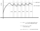
図8及び図9は気温23℃、湿度50%の環境下で画像形成装置Pを用いて定着装置Fが環境に十分なじんだ温度まで冷えたいわゆる朝一コールド状態において、連続プリント6枚を行った時の定着フィルム22の表面温度の変化を示した図である。各ページの画像パターンと温調温度の組合せを後述の設定1〜3にしてテストしている。
In FIGS. 8 and 9, six continuous prints were performed in a so-called morning cold state in which the fixing device F was cooled to a temperature sufficiently familiar to the environment by using the image forming device P in an environment of a temperature of 23 ° C. and a humidity of 50%. It is a figure which showed the change of the surface temperature of the fixing
なお、テストでは記録材としてPBDK A4サイズ64g紙(開直紙)を用いた。プリントは画像形成装置Pを外部ホスト(データ送信装置A)としてのパソコンに接続し、パソコン上から画像パターンをプリントするコマンドを画像形成装置Pに送信した。各設定の詳細は下記の通りである。 In the test, PBDK A4 size 64 g paper (open straight paper) was used as the recording material. For printing, the image forming apparatus P was connected to a personal computer as an external host (data transmitting device A), and a command for printing an image pattern was transmitted to the image forming apparatus P from the personal computer. The details of each setting are as follows.
(設定1)
この設定1は、高濃度画像の次ページの温度ドロップのため標準温調温度では定着不良の例である。設定1では、1枚目を、画像パターンとしては図7に示すRed、Green、B:Blueの各2次色濃度が200%である縦帯画像を配置した画像を207℃温調で定着させた。2枚目以降を同じく画像パターンとしては図7に示すRed、Green、Blueの2次色縦帯を配置した画像において画像濃度だけを140%にして、標準温調温度である200℃で定着させた。
(Setting 1)
This setting 1 is an example of poor fixing at the standard temperature control temperature due to the temperature drop on the next page of the high-density image. In setting 1, an image in which a vertical band image having a secondary color density of 200% for each of Red, Green, and B: Blue shown in FIG. 7 as an image pattern is arranged is fixed to the first image at a temperature control of 207 ° C. rice field. As the same image pattern for the second and subsequent images, in the image in which the secondary color vertical bands of Red, Green, and Blue shown in FIG. 7 are arranged, only the image density is set to 140% and fixed at the standard temperature control temperature of 200 ° C. rice field.
(設定2)
この設定2は、200%より低濃度画像では温度ドロップ小のため標準温調温度でOKの例(例1)である。設定2では、画像パターンとしては同じく図7に示すRed、Green、Blueの2次色縦帯を配置した画像において画像濃度だけを180%にして、標準温調温度である200℃温調で定着させた。
(Setting 2)
This setting 2 is an example (Example 1) in which the standard temperature control temperature is OK because the temperature drop is small in a density image lower than 200%. In setting 2, only the image density is set to 180% in the image in which the secondary color vertical bands of Red, Green, and Blue, which are also shown in FIG. 7, are arranged as the image pattern, and the image is fixed at the standard temperature control temperature of 200 ° C. I let you.
(設定3)
この設定3も、200%より低濃度画像では温度ドロップ小のため標準温調温度でOKの例(例2)である。設定3では、画像パターンとしては同じく図7に示すRed、Green、Blueの2次色縦帯を配置した画像において画像濃度だけを140%にして、標準温調温度である200℃温調で定着させた。
(Setting 3)
This setting 3 is also an example (Example 2) in which the standard temperature control temperature is OK because the temperature drop is small in the density image lower than 200%. In setting 3, only the image density is set to 140% in the image in which the secondary color vertical bands of Red, Green, and Blue, which are also shown in FIG. 7, are arranged as the image pattern, and the image is fixed at the standard temperature control temperature of 200 ° C. I let you.
(設定4)
この設定4は、4枚目に200%画像が来た場合に5枚目標準温調温度で定着性NGの例である。設定4では、1枚目から3枚目までと5枚目と6枚目は画像パターンとしては同じく図7に示すRed、Green、Blueの2次色縦帯を配置した画像において画像濃度だけを180%にして、標準温調温度である200℃にして定着させた。4枚目は画像パターンとして図7に示すRed、Green、Blueの各2次色濃度が200%である縦帯画像を配置した画像を207℃温調で定着させた。
(Setting 4)
This setting 4 is an example of fixability NG at the standard temperature control temperature of the fifth image when a 200% image comes to the fourth image. In setting 4, Red shown in also FIG. 7 is a 5 th and 6 th image pattern from the first sheet to the third sheet, Green, image density only in the image obtained by placing the secondary color vertical band Blue It was set to 180% and fixed at 200 ° C., which is a standard temperature control temperature. For the fourth image, an image in which a vertical band image having a secondary color density of 200% for each of Red, Green, and Blue shown in FIG. 7 was arranged as an image pattern was fixed at a temperature control of 207 ° C.
(設定6)
この設定6は、6枚目に200%画像が来れば標準温調温度でも定着性OKの例である。設定6では、1枚目から5枚目までは画像パターンとしては同じく図7に示すRed、Green、Blueの2次色縦帯を配置した画像において画像濃度だけを180%にして、標準温調温度にて定着させた。6枚目は画像パターンとして図7に示すRed、Green、Blueの各2次色濃度が200%である縦帯画像を配置した画像を200℃温調で定着させた。
(Setting 6 )
This setting 6 is an example of fixability OK even at a standard temperature control temperature when a 200% image comes to the sixth image. In setting 6 , only the image density is set to 180% in the images in which the secondary color vertical bands of Red, Green, and Blue shown in FIG. 7 are arranged as the image patterns for the first to fifth images, and the standard temperature is adjusted. It was fixed at temperature. For the sixth image, an image in which a vertical band image in which each of the secondary color densities of Red, Green, and Blue shown in FIG. 7 was 200% was arranged as an image pattern was fixed at a temperature control of 200 ° C.
なおこの標準温調温度200℃とは朝一からの連続プリント6枚を行う場合に次のように設定した温調温度である。即ち、図7のRed、Green、Blueの2次色縦帯180%の画像において、定着不良の発生がなく、かつ図7のRed、Green、Blueの2次色縦帯140%の画像においてカールが15mm以下になるように設定した温調温度である。 The standard temperature control temperature of 200 ° C. is a temperature control temperature set as follows when six continuous prints are performed from the first morning. That is, in the image of 180% of the secondary color vertical bands of Red, Green, and Blue in FIG. 7, there is no occurrence of fixing failure, and the image of 140% of the secondary color vertical bands of Red, Green, and Blue in FIG. 7 is curled. Is a temperature control temperature set so that is 15 mm or less.
図8の結果から、設定1おいては、
1)定着フィルム22の表面温度は1枚目の画像;すなわち200%の濃度の画像が定着されるときに大きく落ち込み定着不良発生温度の閾値すれすれの温度まで下がってしまっていること、
2)加えて2枚目の画像が濃度140%の画像であっても、もちこたえることなく、定着フィルム22の表面温度はさらに低下して定着不良発生閾値以下まで低下してしまっていること、
3)さらに3枚目になっても定着不良発生閾値を上回ることができないこと
が判る。
From the result of FIG. 8, in setting 1,
1) The surface temperature of the fixing
2) In addition, even if the second image is an image with a density of 140%, the surface temperature of the fixing
3) It can be seen that the threshold value for occurrence of fixing defects cannot be exceeded even when the third sheet is reached.
これは定着装置Fがコールド状態から行ったプリントであるため、定着装置Fが十分に温まっておらず、そこへ濃度が高くトナー量の多い画像が来てしまったことにより、定着フィルム表面から大量の熱が奪われてしまったからである。 Since this is a print performed from the cold state of the fixing device F, the fixing device F is not sufficiently warmed, and an image having a high density and a large amount of toner comes to the printing device F, so that a large amount of images are printed from the surface of the fixing film. This is because the heat of the film has been taken away.
またこの画像濃度が200%である画像による温度低下は、200%画像がプリント開始からもっとも短いタイミングで来ると、すなわち連続プリントの1枚目に来た時に一番大きい。 Further, the temperature drop due to the image having an image density of 200% is the largest when the 200% image comes at the shortest timing from the start of printing, that is, when it comes to the first sheet of continuous printing.
2枚目以降の定着フィルム22の表面温度の落ち込みを回避するために画像濃度が200%の時である1枚目の温調温度を207℃よりも高くすることで、2枚目以降の温度落ち込みを抑制することは原理的に可能である。しかし、その場合に1枚目の温調温度がカール顕著化温度を大きく超えてしまい、カールの顕著化の弊害なくして回避はできない。
By making the temperature control temperature of the first sheet higher than 207 ° C. when the image density is 200% in order to avoid a drop in the surface temperature of the second and subsequent sheets of the fixing
一方、設定2および3では、定着フィルム22の表面温度は設定1の時ほど大きく落ち込むことはなく、2枚目でさらに温度が少し下がっても定着不良発生閾値を下回ることもなく、かつ3枚目からカール顕著化温度を超えることなく推移していることが判る。
On the other hand, in
次に、所定枚数である5枚目の前後で高濃度画像である200%画像が来た場合の定着フィルム22の表面温度推移を図9に示す。
Next, FIG. 9 shows the transition of the surface temperature of the fixing
まず、図9の設定4の結果から、4枚目において200%画像が来た場合にも温度低下が大きく、定着不良発生閾値近くまで、定着フィルム22の表面温度が落ち込んでしまう。そして、5枚目の180%画像の時にも温度低下が大きくなり、標準温調温度である200℃では定着不良が発生してしまっていることが判る。
First, from the result of setting 4 in FIG. 9, even when a 200% image comes in the fourth image, the temperature drops significantly, and the surface temperature of the fixing
一方で、設定5では、5枚目において200%画像が来た場合には、定着フィルム22の表面温度は落ち込むものの、4枚目の時ほど大きくなく、
1)後続紙である6枚目の180%画像を標準温調温度の200℃で定着させても定着不良は起きないこと、
2)さらに設定6の様に6枚目に200%画像が来た場合には標準温調温度の200℃であっても定着不良が起きない温度に保たれている
ことが判る。
On the other hand, in setting 5, when a 200% image comes in the 5th sheet, the surface temperature of the fixing
1) No fixing failure occurs even if the sixth 180% image, which is the subsequent paper, is fixed at the standard temperature control temperature of 200 ° C.
2) Further, when a 200% image comes to the sixth image as in setting 6, it can be seen that the temperature is maintained at a temperature at which fixing failure does not occur even at the standard temperature control temperature of 200 ° C.
これら設定5および6の結果は、5枚目以降で200%画像が来た場合には、定着装置Fが温まり定着フィルム22の表面温度の低下が抑えられていることを示している。
The results of these
図8の結果から朝一コールドスタートからの連続プリントの1枚目の画像において濃度200%の濃度の画像が来た場合には定着フィルム22の表面温度が大きく低下してしまう。その後定着基準温度の200℃でプリントを続けた場合には1枚目の定着器突入時の温度まで復帰するには所定枚数として5枚のプリントが必要であることが判る。この場合はプリント5枚目の後の紙間で復活しているため、5枚のプリントが必要である。
From the result of FIG. 8, when an image having a density of 200% comes in the first image of continuous printing from the cold start in the morning, the surface temperature of the fixing
そして図8および図9の結果から、上記の様に定義された所定枚数である5枚目までの間で、高濃度画像である200%の画像を有するページが来た場合には、
1)そのページの温調温度を高濃度画像用温調温度である207℃に上げるのは無論のこと、
2)その後続ページから所定枚数の5枚以内のページまでの目標温調温度も高濃度画像用温調温度である207℃に上げないと、定着不良が起きることがある
ということが判った。
Then, from the results of FIGS. 8 and 9, when a page having 200% of high-density images comes between the fifth page, which is the predetermined number defined as described above, the page has 200% of the images.
1) It goes without saying that the temperature control temperature on that page should be raised to 207 ° C, which is the temperature control temperature for high-density images.
2) It was found that fixing failure may occur unless the target temperature control temperature from the subsequent pages to a predetermined number of 5 pages or less is also raised to 207 ° C., which is the temperature control temperature for high-density images.
次にこの定着不良を回避することを検討した結果である、設定7及び8での測定結果を図10に示す。
Next, FIG. 10 shows the measurement results at
(設定7)
この設定7は全て高濃度画像用温調温度207℃だとカールNGの例(例1)である。設定7としては設定1と同じ画像の組合せで1枚目だけが200%の高濃度画像で2枚目以降6枚目までが140%画像で、温調温度をすべて207℃にした。
(Setting 7)
This setting 7 is an example of curl NG (Example 1) when the temperature control temperature for high-density images is 207 ° C. As setting 7, in the same combination of images as in setting 1, only the first image was a high-density image of 200%, the second to sixth images were 140% images, and the temperature control temperature was set to 207 ° C.
(設定8)
この設定8も全て高濃度画像用温調温度207℃だとカールNGの例(例2)である。またさらに設定8として、設定7と同じ温調温度設定ですべての画像が高濃度画像である200%画像の時の定着フィルム22の表面温度を測定した結果も図10に示した。
(Setting 8)
This setting 8 is also an example of curl NG (Example 2) when the temperature control temperature for high-density images is 207 ° C. Further, as setting 8, the result of measuring the surface temperature of the fixing
図10の結果からわかるように、設定7の様に200%画像ページの次ページが140%濃度であったとしても標準温調温度ではなく207℃で温調すれば、定着不良は発生しない。しかしカールに関しては、所定枚数である5枚目を過ぎた6枚目においてにカール発生閾値を超えて顕著化することが判る。 As can be seen from the result of FIG. 10, even if the next page of the 200% image page has a concentration of 140% as in setting 7, if the temperature is controlled at 207 ° C. instead of the standard temperature control temperature, no fixing failure occurs. However, it can be seen that the curl exceeds the curl generation threshold value and becomes remarkable in the sixth sheet after the fifth sheet, which is a predetermined number.
また設定8の様に、全てのページで温調温度を高濃度画像用温調温度である207℃にすれば、すべての画像が200%画像であったとしても定着不良の発生はない。しかし、この設定8も設定7と同様にカールに関しては、所定枚数である5枚目を過ぎた6枚目においてにカール発生閾値を超えて顕著化することが判る。
Further, if the temperature control temperature is set to 207 ° C., which is the temperature control temperature for high-density images, on all pages as in setting 8, no fixing failure occurs even if all the images are 200% images. However, it can be seen that in this
つまり、コールドスタートの連続プリントにおいて、高濃度画像ページ定着に伴う所定枚数内の定着不良抑制のために目標温調温度を一律に高濃度画像用温調温度にすることは定着性改善に有効ではあるものの、カールが顕著化してしまう。 In other words, in cold start continuous printing, it is effective to uniformly set the target temperature control temperature to the temperature control temperature for high density images in order to suppress fixing defects within a predetermined number of sheets due to fixing of high density image pages. However, the curl becomes noticeable.
(温度検出と上げ方のフローチャート)
図8乃至図10の結果より、実施例1では次のような目標温調温度設定としている。画像濃度200%以上(あらかじめ設定された閾値以上の画像濃度)の画像を有するページを検出した場合にはそのページだけでなく、その後続ページにおいても所定枚数である5枚目まではフィルム22の表面温度の落ち込みを加熱装置の加熱で補う。そのため、画像濃度によらず定着装置Fの温調温度を標準温調温度200℃(第1の温調温度)に対して補正を行い、目標温調温度を7℃上げた高濃度画像用温調温度207℃(第2の温調温度)に設定する。そして所定枚数を過ぎた6枚目において標準温調温度200℃に戻す。
(Flowchart of temperature detection and raising)
From the results of FIGS. 8 to 10, in Example 1, the target temperature control temperature is set as follows. When a page having an image with an image density of 200% or more (an image density equal to or higher than a preset threshold value) is detected, not only that page but also the subsequent pages up to the fifth sheet, which is a predetermined number, are formed on the
これをまとめると次の通りである。制御部31は、記録材を順次に搬送して複数ページの画像を連続してプリントする場合に、ビデオコントローラ30によって、連続のプリントの開始から所定枚数までの各ページの画像濃度情報を取得し、
1)あらかじめ設定された閾値以上(200%以上)の画像濃度を有するページが含まれない場合は、目標温調温度を所定の第1の温調温度(200℃)に設定して連続のプリントの定着を行い、
2)閾値以上の画像濃度を有するページが含まれる場合には、目標温調温度を第1の温調温度より高い所定の第2の温調温度(207℃)に設定してそのページの記録材の定着を行い、
3)閾値以上の画像濃度を有するページの次のページから前記所定枚数までのページの記録材は画像濃度に関わらず目標温調温度を第2の温調温度に設定して定着を行う。そして、所定枚数より後のプリントにおいては目標温調温度を第2の温調温度から第1の温調温度に戻す。ここで、上記の所定枚数は加圧ローラ温度が1枚目の温度に復帰するまでに要する連続プリント枚数として定義される。
This is summarized as follows. When the recording material is sequentially conveyed and the images of a plurality of pages are continuously printed, the
1) If a page having an image density equal to or higher than a preset threshold value (200% or higher) is not included, the target temperature control temperature is set to a predetermined first temperature control temperature (200 ° C.) for continuous printing. And settled
2) If a page with an image density equal to or higher than the threshold value is included, set the target temperature control temperature to a predetermined second temperature control temperature (207 ° C.) higher than the first temperature control temperature and record the page. Fix the material,
3) The recording materials of the pages from the next page of the page having the image density equal to or higher than the threshold value to the predetermined number of pages are fixed by setting the target temperature control temperature to the second temperature control temperature regardless of the image density. Then, in the printing after the predetermined number of sheets, the target temperature control temperature is returned from the second temperature control temperature to the first temperature control temperature. Here, the above-mentioned predetermined number of sheets is defined as the number of continuous prints required for the pressure roller temperature to return to the temperature of the first sheet.
具体的な設定方法は図1のフローチャートに従う。図1のフローチャートは定着装置Fの目標温調温度設定の仕方を示している。CNTとは図1のフローチャート上で処理されたページの現在カウントのことである。後述する図11、図12、図13におけるCNTについても同様である。また所定枚数とは、加圧ローラ温度が1枚目の温度に復帰するまでに要する連続プリント枚数で、かつ連続のプリントの開始から定着装置がトナー量の影響を受けにくくなるくらい温めるまでのページ枚数であり、本実施例においては、所定枚数は5となっている。 The specific setting method follows the flowchart of FIG. The flowchart of FIG. 1 shows how to set the target temperature control temperature of the fixing device F. The CNT is the current count of pages processed on the flowchart of FIG. The same applies to the CNTs in FIGS. 11, 12, and 13 which will be described later. The predetermined number of sheets is the number of continuous prints required for the pressure roller temperature to return to the temperature of the first sheet, and is a page from the start of continuous printing to the warming of the fixing device so that it is not easily affected by the amount of toner. The number of sheets is 5, and in this embodiment, the predetermined number of sheets is 5.
図1を参照して、画像形成装置Pがプリント信号を受け取ると(S20)、まずジョブ内ページカウント(以降、CNTと略記)をゼロにする。つぎに定着装置Fの温まり具合を検出するためサーミスタ26の示す温度を取得する(S21)。このサーミスタ26の示す温度で定着装置Fの、プリント開始時における立ち上げ時温度が所定の閾値未満、本実施例においては42℃未満かどうかを判断する(S22)。Yesすなわちコールド状態であると判断するとS23へ進む。Noである場合には温調温度補正を行わない目標温調温度設定(第1の温調温度:ここでは目標温調温度を200℃に設定)を行う(S30)。
With reference to FIG. 1, when the image forming apparatus P receives the print signal (S20), the in-job page count (hereinafter abbreviated as CNT) is first set to zero. Next, the temperature indicated by the
S23では制御処理中のページカウントを認識するためCNTに1を足す。そしてCNTが所定枚数である5以下であるかどうか(6より小さいかどうか)を判断する(S24)。Noである場合には温調温度補正を行わない目標温調温度設定(目標温調温度を200℃に設定)を行い(S30)、Yesである場合には画像濃度取得を行う(S25)。
In S23, 1 is added to CNT in order to recognize the page count during the control process. Then, it is determined whether or not the number of CNTs is 5 or less (whether or not it is smaller than 6), which is a predetermined number (S24). If No, the target temperature control temperature is set (the target temperature control temperature is set to 200 ° C.) without performing temperature control temperature correction (S 30 ), and if Yes, the image density is acquired (S25). ..
画像濃度を取得したのち、200%以上のdotの有無を確認する(S26)。Yesの場合には、温調温度補正し目標温調温度を第1の温調温度より所定に高い第2の温調温度、ここでは207℃に設定する(S27)。そののちのページは所定枚数5枚目までは画像にかかわらず207℃にするので、(S28)にてCNTに1を足したのち、CNTが6より小さいかを判断する(S29)。Yesの場合はそのまま207℃に設定し(S27)つづけ、Noの場合(CNTが6以上の場合)には目標温調温度を200℃に設定し(S30)、その後は7枚目以降の温調温度検定制御(S31)へ進む。 After acquiring the image density, it is confirmed whether or not there is a dot of 200% or more (S26). In the case of Yes, the temperature control temperature is corrected and the target temperature control temperature is set to a second temperature control temperature, which is 207 ° C., which is predetermined higher than the first temperature control temperature (S27). Since the subsequent pages are set to 207 ° C. up to the fifth predetermined number of pages regardless of the image, 1 is added to the CNT in (S28), and then it is determined whether the CNT is smaller than 6 (S29). In the case of Yes, it is set to 207 ° C as it is (S27), and in the case of No (when CNT is 6 or more), the target temperature control temperature is set to 200 ° C (S30), and then the temperature of the seventh and subsequent sheets is set. Proceed to temperature control test control (S31).
一方、S26にてNoの場合には目標温調温度を200℃に設定し(S32)、5枚目までは画像濃度に基づいて目標温調温度を上げるかどうかの判断を繰り返すため、S23に戻る。
On the other hand, if No in S26, the target temperature control temperature is set to 200 ° C. (S32) , and up to the fifth image, the determination of whether to raise the target temperature control temperature is repeated based on the image density. return.
制御部31による画像濃度情報の取得(S25)はプリント開始時における定着装置Fの立ち上げ時温度が所定の閾値未満である場合(S22のYes)だけである。
The acquisition of the image density information (S25) by the
また、S26においてYesとなった場合で、かつ実行されるプリントジョブのページ枚数がもともと前記所定枚数(本実施例では5枚)以下である1〜5枚である場合には次のようになる。 Further, when Yes in S26 and the number of pages of the print job to be executed is 1 to 5 which is originally the predetermined number (5 in this embodiment) or less, the result is as follows. ..
即ち、処理ページのカウント数であるCNTがそのプリントジョブの最終枚数まで進んでも所定枚数を超えた枚数である6以上になることはない。そのため、S29でNoと判断されず目標温調温度は最終枚数までS27において207℃に設定されてプリントジョブが終了する。 That is, even if the CNT which is the count number of the processing page advances to the final number of the print job, it does not exceed 6 which is the number exceeding the predetermined number. Therefore, it is not determined as No in S29, the target temperature control temperature is set to 207 ° C. in S27 up to the final number of sheets, and the print job is completed.
(ポイント;実施例1の効果)
以下具体的に実施例1の構成の効果をテストした結果を説明する。テスト方法としては朝一連続プリント6枚を後述する画像パターンの組み合わせを変えながら行い、画像不良の有無を比較例構成と比較した。なお比較例としては以下の一般に公知の構成をもちいた。
(Point; effect of Example 1)
The results of specifically testing the effects of the configuration of Example 1 will be described below. As a test method, six continuous prints in the morning were performed while changing the combination of image patterns described later, and the presence or absence of image defects was compared with the comparative example configuration. As a comparative example, the following generally known configuration was used.
(比較例1)
比較例1の構成は、テストページ全てにおいて画像濃度に関わらず温調温度補正を行わない、すなわちすべてのページで標準温調温度に設定した構成である。
(Comparative Example 1)
The configuration of Comparative Example 1 is a configuration in which temperature control temperature correction is not performed on all test pages regardless of the image density, that is, the standard temperature control temperature is set on all pages.
(比較例2)
比較例2の構成は、テストページ全てにおいて画像検出を行う。その結果、濃度の高い(濃度200%以上の)画像を有するページを検出した場合にだけ、そのページ定着時の温調温度補正をおこない目標温調温度を7℃上げた高濃度画像用温調温度に設定する。濃度の高い(濃度200%以上の)画像を有するページを検出しない場合は標準温調温度に設定する。
(Comparative Example 2)
In the configuration of Comparative Example 2, image detection is performed on all test pages. As a result, only when a page having a high density (density 200% or more) image is detected, the temperature control temperature correction at the time of fixing the page is performed and the target temperature control temperature is raised by 7 ° C. for high density image temperature control. Set to temperature. If a page with a high density (200% or more density) image is not detected, set the standard temperature control temperature.
(比較例3)
比較例3の構成は、テストページ全てにおいて画像濃度に関わらず温調温度補正を行ったのと同じ値、すなわち目標温調温度を7度上げた高濃度画像用温調温度に設定した構成である。
(Comparative Example 3)
The configuration of Comparative Example 3 is the same value that the temperature control temperature correction was performed regardless of the image density on all the test pages, that is, the target temperature control temperature was set to the temperature control temperature for high density images increased by 7 degrees. be.
(テスト方法)
気温23℃湿度50%の環境で定着装置Fを含む画像形成装置Pが環境温度に十分になじんだ朝一コールド状態から連続6枚のプリントを行った。紙としてはPBDK A464g紙(開直紙)を用いた。プリントは画像形成装置Pを外部ホストAとしてのパソコンに接続し、パソコン上から画像パターンをプリントするコマンドを画像形成装置Pに送信した。
(Test method)
In an environment where the temperature was 23 ° C. and the humidity was 50%, the image forming apparatus P including the fixing apparatus F printed 6 sheets continuously from the cold state in the morning when the image forming apparatus P was sufficiently accustomed to the environmental temperature. As the paper, PBDK A464g paper (open straight paper) was used. For printing, the image forming apparatus P was connected to a personal computer as an external host A, and a command for printing an image pattern was transmitted to the image forming apparatus P from the personal computer.
(画像パターンについて)
また各ページの画像パターンとしては、以下の3つの画像組合せを用いて評価した。
(About image patterns)
Further, as the image pattern of each page, the following three image combinations were used for evaluation.
(画像組合せ1)
1枚目〜6枚目まですべて、図7に示すように、ページ右側と左側にそれぞれ、200%2次色Red、200%2次色Green、200%2次色Blueの3つの帯状パターンを束ねて1つの帯にしたパターン配置した画像でプリントする。この画像を以下200%(R,G,B)パターンと表記する。
(Image combination 1)
As shown in FIG. 7, all the 1st to 6th sheets have three strip patterns of 200% secondary color Red, 200% secondary color Green, and 200% secondary color Blue on the right side and the left side of the page, respectively. Print the images in a pattern that is bundled into a single band. This image is hereinafter referred to as a 200% (R, G, B) pattern.
(画像組合せ2)
1枚目は上記200%(R,G,B)パターンで、2枚目〜6枚目の画像はR,G&Bの各2次色濃度だけ140%にして、それら配置は先記200%(R,G,B)パターンと同じく図7のようにした画像パターンでプリントする。この画像を以下140%(R,G,B)パターンと表記する。
(Image combination 2)
The first image is the above 200% (R, G, B) pattern, the second to sixth images are 140% for each secondary color density of R, G & B, and their arrangement is 200% (the above). Similar to the R, G, B) pattern, the image pattern as shown in FIG. 7 is printed. This image is hereinafter referred to as a 140% (R, G, B) pattern.
(画像組合せ3)
2枚目のみは上記200%(R,G,B)パターンで、1枚目および3枚目〜6枚目は上記140%(R,G,B)パターンでプリントする。
(Image combination 3)
Only the second sheet is printed with the above 200% (R, G, B) pattern, and the first sheet and the third to sixth sheets are printed with the above 140% (R, G, B) pattern.
(テスト結果)
実際にこれら3つの画像組合せ設定で定着性評価として定着不良をみつつ、紙搬送としてカールを評価した結果を以下の表1、表2、表3に順次しめす。
(test results)
Tables 1, 2, and 3 below show the results of evaluating curl as paper transport while actually observing fixing defects as a fixability evaluation in these three image combination settings.

表中の〇、△、×は画像不良ないし定着後の紙のカールのレベルを表している。 〇, Δ, and × in the table indicate the level of curl of the paper after image defect or fixing.
定着不良の評価において、○は発生の無い状態、×は定着不良が発生している状態、△は×レベルではないものの軽度なレベルで定着不良の発生が認められる状態を表している。 In the evaluation of fixing failure, ◯ indicates a state in which no fixing failure has occurred, × indicates a state in which fixing failure has occurred, and Δ indicates a state in which the occurrence of fixing failure is recognized at a mild level although it is not at the × level.
また紙のカールの評価においては、○はカール(カール量)が15mm未満の状態、×は30mm以上のカールが発生している状態、△は15mm以上、30mm未満のカール発生が認められる状態を表している。紙のカールは大きいほど排出トレイ16上の積載性が低下し、特に30mmを超えると用紙のコバ折れなどが発生するリスクが増大する。
In the evaluation of paper curl, ○ indicates a state in which the curl (curl amount) is less than 15 mm, × indicates a state in which curl of 30 mm or more is generated, and Δ indicates a state in which curl of 15 mm or more and less than 30 mm is observed. Represents. The larger the curl of the paper, the lower the loadability on the
カール量は紙のカールの度合いを示す量である。上記のカール量は、図14の(a)のようにカールした紙Sを、カールしている縁Saを水平にして静かに吊るし、水平板17上にカールの状態を(b)に示すように書き写す。そして、書き写したカール線Cの両端部CaとCbとを結ぶ直線Dとカール線Cで直線Dから最も離れた部分との間の距離Lを測定した値(mm)である。
The amount of curl is an amount indicating the degree of curl of paper. The curl amount is such that the curled paper S as shown in (a) of FIG. 14 is gently hung with the curled edge Sa horizontal, and the curled state is shown in (b) on the
表1に示した画像組合せ1の評価結果より、比較例1の構成では6枚目を除きすべてのページにおいて定着不良が200%(R,G,B)部において発生していたことが判る。比較例2と比較例3は今回の画像組合せ1では、すべてのページにおいて同じ目標温調温度を設定し同じ結果だった。すなわち定着不良の発生はないものの、カールに関しては図10の設定8に示したように所定枚数である5枚目の次のページである6枚目においても目標温調温度設定が高いために、カールが顕著化している。
From the evaluation results of the
一方で実施例1の構成においてはフィルム22の表面温度が回復するまでの所定枚数の区間、すなわち1〜5枚目のみにおいて目標温調温度を上げていることから全てのページで定着不良とカールの発生はない。つまり、画像不良と搬送性を両立したレベルはすべての比較例よりも良いことが判る。
On the other hand, in the configuration of Example 1, since the target temperature control temperature is raised only in a predetermined number of sections until the surface temperature of the
表2の画像組合せ2の評価結果より、比較例1の構成では1〜5枚目まで2次色部における定着不良の発生が認められた。比較例2においては1枚目の定着不良発生はなかったものの、濃度が200%以上でない画像は目標温調温度をあげないため、図8の設定1に示したフィルム表面温度になるため、2枚目以降4枚目までのページでは定着不良が発生してしまっている。とくに2枚目と3枚目の定着不良は×レベルの発生であった。比較例3においては定着不良の発生はないものの、フィルム22が温まってきている6枚目においても目標温調温度が高いままになってしまっているためにカールが顕著化している。
From the evaluation results of the image combination 2 in Table 2, in the configuration of Comparative Example 1, the occurrence of fixing failure in the secondary color portion was observed from the 1st to 5th images. In Comparative Example 2, although the first fixing failure did not occur, the target temperature control temperature was not raised for the image whose density was not 200% or more, and the film surface temperature shown in setting 1 of FIG. 8 was obtained. Fixing failure has occurred on the pages from the first page to the fourth page. In particular, the poor fixing of the second and third sheets was the occurrence of x level. In Comparative Example 3, although no fixing failure occurred, the curl became remarkable because the target temperature control temperature remained high even in the sixth film in which the
一方で実施例1の構成においては、図8に示された2枚目以降は標準温調温度200℃温調とした場合にフィルム22の表面温度が回復するまでの区間、すなわち2〜5枚目において目標温調温度を1枚目同様に上げて207℃にしている。このことから全ての枚数に定着不良の発生はない。またカールも定着フィルム22の表面温度が回復した所定枚数後のページである6枚目において目標温調温度を下げて標準温調温度200℃にもどしていることから良好であった。
On the other hand, in the configuration of Example 1, the second and subsequent films shown in FIG. 8 are the sections until the surface temperature of the
このように実施例1の構成は画像組み合わせ2においても、すべての比較例に対して定着不良とカールを両立した良好な結果が得られることが判る。 As described above, it can be seen that the configuration of the first embodiment gives good results in which both the fixing defect and the curl are compatible with respect to all the comparative examples even in the image combination 2.
表3の画像組合せ3の評価結果より、比較例1の構成では2〜5枚目まで2次色部における定着不良の発生が認められた。また比較例2においては3〜5枚目において定着不良の発生が認められた。3枚目以降にも定着不良の発生が認められるのは、2枚目に高濃度の画像である200%RGBがあるがために、次のページの3枚目で定着フィルム22の表面温度が低下しているからである。比較例3構成においては定着不良の発生はないものの、6枚目にカールの発生が認められた。
一方で実施例1の構成においては定着不良およびカールの発生はともになく、良好であった。
From the evaluation results of the
Both without occurrence of fixing failure and curl in the configuration of Example 1 in one hand, was good.
以上示した様に、画像組合せ1〜3すべての評価結果において実施例1の構成はすべての比較例よりも定着不良とカールが両立された良好な結果になっていることが判る。
As shown above, in all the evaluation results of the
《実施例2》
実施例2の構成について説明する。本実施例2の基本構成は実施例1に同じである。異なるのは、濃度の高い画像(200%2次色)を検知したページの定着時の目標温調温度である高濃度画像用温調温度(第2の温調温度)において、フィルム22の温度が復帰するまでの所定枚数内を全て一律に同じ目標温調温度に設定するのではない。即ち、途中のページで温度をさげて設定する。つまり、第2の温調温度は、連続のプリントの開始からのページ枚数が増えると温度が下がるように設定されたことを特徴とする。
<< Example 2 >>
The configuration of the second embodiment will be described. The basic configuration of the second embodiment is the same as that of the first embodiment. The difference is the temperature of the
これにより紙がテスト環境下で放置され、紙の水分量が開直紙の状態から変化した場合でも、定着性とカールを良好に両立でき、実施例1の構成よりもさらに定着性と搬送性(カール)とを良く両立した画像形成装置を得ることができる。以下、本実施例2の構成を説明していく。 As a result, even when the paper is left in a test environment and the water content of the paper changes from the state of open straight paper, both fixability and curl can be well achieved, and fixability and transportability are further improved as compared with the configuration of Example 1. It is possible to obtain an image forming apparatus that is well compatible with (curl). Hereinafter, the configuration of the second embodiment will be described.
(ポイント;実施例2 温度検出&上げ方のフローチャート)
図11のフローチャートに示すように本実施例2の画像形成装置はプリント信号を受け取る(S40)と、まずジョブ内ページカウント(以降CNTと略記)をゼロにする。つぎに定着装置Fの温まり具合を検出するためサーミスタ26の示す温度を取得する(S41)。このサーミスタ26の示す温度で定着器が42℃以下かどうかを判断し(S42)、Yesすなわちコールド状態であると判断するとS43へ進む。Noである場合には温調温度補正を行わない目標温調温度設定(目標温調温度を200℃(第1の温調温度)に設定)を行う(S51)。
(Point; Example 2 Flow chart of temperature detection & raising)
As shown in the flowchart of FIG. 11, when the image forming apparatus of the second embodiment receives the print signal (S40), the page count in the job (hereinafter abbreviated as CNT) is first set to zero. Next, the temperature indicated by the
S43では制御処理中のページカウントを認識するためCNTに1を足す。そしてCNTが所定枚数である5枚目以下であるかどうか(6より小さいかどうか)を判断し(S44)、Noである場合には温調温度補正を行わない目標温調温度設定(目標温調温度を200℃(第1の温調温度)に設定)を行う(S51)。Yesである場合には画像濃度取得を行う(S45)。 In S43, 1 is added to CNT in order to recognize the page count during the control process. Then, it is determined whether or not the number of CNTs is 5 or less (smaller than 6), which is a predetermined number (S44), and if No, the temperature control temperature is not corrected and the target temperature control temperature is set (target temperature). The temperature control is set to 200 ° C. (first temperature control temperature)) (S51). If Yes, the image density is acquired (S45).
画像濃度を取得したのち、200%以上のdotの有無を確認する(S46)。Yesの場合には、再度CNTを確認し、目標温調温度を第2の温調温度(207℃)より低く第1の温調温度(200℃)より高い所定の第3の温調温度(ここでは204℃)に切り替える枚目である5枚目であるかをみる。 After acquiring the image density, it is confirmed whether or not there is a dot of 200% or more (S46). In the case of Yes, the CNT is confirmed again, and the target temperature control temperature is set to a predetermined third temperature control temperature (200 ° C.) lower than the second temperature control temperature (207 ° C.) and higher than the first temperature control temperature (200 ° C.). Here, it is checked whether it is the fifth sheet which is the fifth sheet to be switched to 204 ° C.).
即ち、CNTが5より小さいかを見る(S47)。S47にてNoと判断されるのはCNTが5枚目の時だけであり、このとき目標温調温度を204℃(第3の温調温度)に設定し(S49)、そののち次のページの処理に移るため(S43)へ戻る。一方、S47にて、CNTが5より小さくYesと判断される場合には、目標温調温度を207℃(第2の温調温度)に設定する(S48)。 That is, it is checked whether the CNT is smaller than 5 (S47). No is judged in S47 only when the CNT is the 5th sheet. At this time, the target temperature control temperature is set to 204 ° C. (third temperature control temperature) (S49), and then the next page. Return to (S43) in order to move to the process of. On the other hand, if the CNT is smaller than 5 and is determined to be Yes in S47, the target temperature control temperature is set to 207 ° C. (second temperature control temperature) (S48).
これらの一連の制御フローにより、本実施例2において所定枚数である5枚より大きい6枚以上の連続プリントジョブが来た場合の、各ページの目標温調温度について説明する。すなわち、プリント開始1枚目から4枚目の間のページで濃度が200%以上の画像があった場合(すなわちS47でYesの場合)には、そのページを207℃に設定する(S48)。以降プリント開始から4枚目までは、S47でYesで有り続けるため、画像濃度にかかわらず目標温調温度を207℃に設定し続け、5枚目になって画像濃度にかかわらず204℃に設定する(S49)。 The target temperature control temperature of each page will be described when 6 or more continuous print jobs, which are larger than the predetermined number of 5 sheets, come in the second embodiment by these series of control flows. That is, when there is an image having a density of 200% or more on the page between the first to fourth print start sheets (that is, in the case of Yes in S47), that page is set to 207 ° C. (S48). After that, from the start of printing to the 4th sheet, since it continues to be Yes in S47, the target temperature control temperature is continuously set to 207 ° C regardless of the image density, and it is set to 204 ° C regardless of the image density on the 5th sheet. (S49).
また、5枚目においてのみ濃度200%以上の画像が検知された場合(すなわちS47でNoの場合)には、5枚目の目標温調温度を204℃に設定する(S49)。また6枚目は所定枚数の画像濃度に関わらず200℃に設定され、7枚目以降は、画像濃度とは関係ない所定の目標温調温度決定フローに従い200℃以下の目標温調温度に設定されて制御が行われる。 When an image having a density of 200% or more is detected only on the fifth image (that is, when No in S47), the target temperature control temperature of the fifth image is set to 204 ° C. (S49). The sixth image is set to 200 ° C. regardless of the image density of a predetermined number of images, and the seventh and subsequent images are set to a target temperature control temperature of 200 ° C. or less according to a predetermined target temperature control temperature determination flow irrelevant to the image density. Is controlled.
またS46においてYesとなった場合において、連続枚数が所定枚数より少ない1〜4枚目までの連続プリントジョブが来た場合は次のようになる。即ち、処理ページのカウント数であるCNTがそのプリントジョブの最終枚数まで進んでも所定枚数である5に到達することはなく、S47においてYesであり続ける。そのため、目標温調温度はS48にてプリントジョブの最終枚数まで207℃に設定され続けて、プリントジョブは終了する。 Further, in the case of Yes in S46, when the continuous print jobs of the 1st to 4th sheets in which the number of continuous sheets is less than the predetermined number comes, the process is as follows. That is, even if the CNT which is the count number of the processing page advances to the final number of the print job, it does not reach the predetermined number of 5 and continues to be Yes in S47. Therefore, the target temperature control temperature continues to be set to 207 ° C. until the final number of print jobs in S48, and the print job ends.
(ポイント;実施例2の効果)
以下具体的に実施例2の構成の効果を調べたテスト結果を説明する。テスト方法としては朝一連続プリント6枚を画像パターンの組み合わせを変えながら行い、画像不良の有無とカール量を実施例1の構成と比較した。
(Point; effect of Example 2)
Hereinafter, the test results of examining the effect of the configuration of Example 2 will be specifically described. As a test method, six continuous prints were performed in the morning while changing the combination of image patterns, and the presence or absence of image defects and the amount of curl were compared with the configuration of Example 1.
(テスト方法)
気温23℃湿度35%の環境で定着装置Fを含む画像形成装置Pが環境温度に十分になじんだ朝一コールド状態から連続6枚のプリントを行った。紙としてはPBDK A464g紙をテスト環境である気温23℃湿度35%の環境下で30時間放置したものを用いた。プリントは画像形成装置Pを外部ホストAとしてのパソコンに接続し、パソコン上から画像パターンをプリントするコマンドを画像形成装置Pに送信した。
(Test method)
In an environment where the temperature was 23 ° C. and the humidity was 35%, the image forming apparatus P including the fixing apparatus F printed 6 sheets continuously from the cold state in the morning when the image forming apparatus P was sufficiently accustomed to the environmental temperature. As the paper, PBDK A464 g paper was used, which was left for 30 hours in an environment of a temperature of 23 ° C. and a humidity of 35%, which is a test environment. For printing, the image forming apparatus P was connected to a personal computer as an external host A, and a command for printing an image pattern was transmitted to the image forming apparatus P from the personal computer.
(画像パターンについて)
また各ページの画像パターンとしては、実施例1の評価に用いたのと同じ3つの画像組合せ(1〜3)にして評価した。
(About image patterns)
Further, as the image pattern of each page, the same three image combinations (1 to 3) used for the evaluation of Example 1 were used for evaluation.
(テスト結果)
実際にこれら3つの画像組合せ設定で定着性として定着不良と紙搬送としてカールを評価した結果を以下の表4、表5、表6に順次しめす。
(test results)
The results of actually evaluating the fixing failure as the fixability and the curl as the paper transport in these three image combination settings are shown in Tables 4, 5 and 6 below in order.
設定1での評価結果を上記表4に示す。表4から判るようにこの画像組合せ1での評価では、目立った有意差は見られなかった。
The evaluation results in setting 1 are shown in Table 4 above. As can be seen from Table 4, no significant difference was found in the evaluation with this
画像組合せでの評価結果を上記表5に示す。表5から判るように画像組合せ2にして評価した場合には実施例1の構成に比べてさらに良好な結果になっていることがわかる。 The evaluation results of the image combinations are shown in Table 5 above. As can be seen from Table 5, when the image combination 2 is used for evaluation, it can be seen that the results are even better than the configuration of Example 1.
すなわち、実施例1の構成ではPBDK A464g紙をテスト環境である気温23℃湿度35%の環境下で30時間放置したものを用いた場合には5枚目および6枚目においてカールの顕著化がわずかに認められた。これは紙がテスト環境に放置されたため、紙の水分量が開直の状態から変化し、ページ内で不均一化したことで紙自体がカールの生じやすい条件になってしまったためと思われる。 That is, in the configuration of Example 1, when PBDK A464 g paper was left for 30 hours in an environment of a temperature of 23 ° C. and a humidity of 35%, which is a test environment, curls became noticeable on the 5th and 6th sheets. Slightly recognized. It is considered that this is because the paper was left in the test environment, the water content of the paper changed from the open state, and the paper itself became non-uniform due to the unevenness in the page, which made the paper itself prone to curl.
本実施例2の構成においては、5枚目および6枚目のカールはいずれも良好な結果になった。これは5枚目の目標温調温度を実施例1の構成よりも下げていることで5枚目、および6枚目のカールが良化したためである。 In the configuration of the second embodiment, the curls of the fifth and sixth sheets both gave good results. This is because the curls of the 5th and 6th sheets are improved by lowering the target temperature control temperature of the 5th sheet from the configuration of the first embodiment.
画像組合せ3での評価結果を上記表6に示した。表6から判るように画像組合せ3にして評価した場合でも画像組合せ2の場合と同様に、実施例1の構成に比べてさらに良好な結果になっていることがわかる。すなわち実施例1の構成では5枚目および6枚目においてカールの顕著化がわずかに認められたが、本実施例2の構成においては5枚目および6枚目のカールはいずれも良好な結果になった。これは画像組合せ2での結果と同様に5枚目の目標温調温度を実施例1の構成よりも下げていることで、5枚目、および6枚目のカールが良化したためと考えられる。
The evaluation results of the
以上示した様に、画像組合せ1では有意差はなかったものの、画像組合せ2および画像組合せ3の評価結果においては有意差があり、総じて実施例2の構成は実施例1の構成よりもさらに定着不良とカールが両立された良好な結果になっていることが判る。
As shown above, although there was no significant difference in the
《実施例3》
実施例3の構成について説明する。実施例1および実施例2の構成では一律に定着装置Fのサーミスタ26の温度が42℃未満であれば一律に同じ制御に従っていたが、本実施例ではここを32℃未満の場合と32℃以上42℃未満の場合で目標温調温度の設定制御を変える。
<< Example 3 >>
The configuration of the third embodiment will be described. In the configurations of Example 1 and Example 2, if the temperature of the
即ち、第2の温調温度について定着装置Fの温まり具合に応じてその温度が変更される(温度が可変される)構成にするのである。このように定着装置Fの温まり状態に応じて高濃度画像用温調温度を変えることで、画像形成装置が十分に環境になじんだ朝一コールド状態よりも温まった状態においても定着不良とカールを両立させた良好な画像形成装置を得ることができる。 That is, the temperature of the second temperature control temperature is changed (the temperature is variable) according to the degree of warming of the fixing device F. By changing the temperature control temperature for high-density images according to the warming state of the fixing device F in this way, both poor fixing and curling can be achieved even in a state where the image forming device is warmer than the cold state in the morning when the image forming device is sufficiently accustomed to the environment. It is possible to obtain a good image forming apparatus.
図12および図13にプリントジョブ信号を受け取ったのちの本実施例3の目標温度設定制御のフローチャートを示す。 12 and 13 show a flowchart of the target temperature setting control of the third embodiment after receiving the print job signal.
まず、図12に示すように、本実施例3の画像形成装置はプリント信号を受け取る(S60)と、まずジョブ内ページカウント(以降CNTと略記)をゼロにする。つぎに定着装置Fの温まり具合を検出するためサーミスタ26の示す温度を取得する(S61)。このサーミスタ26の示す温度でまず定着器が32℃未満かどうかを判断し(S62)、Yesと判断すると(S63)へ進む。そして、S63〜S72の制御が行われる。このS63〜S72の制御は実施例2の図11におけるS43〜S52までのフローと同じフローで制御が行われるため、説明は割愛する。
First, as shown in FIG. 12, when the image forming apparatus of the third embodiment receives the print signal (S60), the in-job page count (hereinafter abbreviated as CNT) is first set to zero. Next, the temperature indicated by the
本実施例3の特徴はS62の判断にてNoとなる場合にある。すなわち、定着装置Fの温まり具合として検知したサーミスタ温度が32℃以上のケースで画像中の濃度情報に基づく目標温調温度制御を行う場合に、サーミスタ温度が32℃未満の場合とは異なる制御(A1以下の制御)を行うことである。 The feature of the third embodiment is that the judgment of S62 is No. That is, when the thermistor temperature detected as the warming condition of the fixing device F is 32 ° C. or higher and the target temperature control temperature is controlled based on the concentration information in the image, the control is different from the case where the thermistor temperature is less than 32 ° C. (Control of A1 or less) is performed.
図13にA1以下の制御を示したので以下説明する。S62の判断にてNoとなってA1に入ると、まずサーミスタ温度が42℃未満かどうかを判断する(S73)。S73でNoと判断すると、すなわち定着器が温まっていると判断すると温調温度補正を行わない目標温調温度設定(目標温調温度を200℃に設定)を行う(S82)。 Since the control of A1 or less is shown in FIG. 13, it will be described below. When the judgment of S62 becomes No and enters A1, it is first judged whether the thermistor temperature is less than 42 ° C. (S73). If No is determined in S73, that is, if it is determined that the fuser is warm, a target temperature control temperature setting (target temperature control temperature is set to 200 ° C.) without temperature control temperature correction is performed (S82).
一方、S73にてYesと判断すると、制御処理中のページカウントを認識するためCNTに1を足す(S74)。そしてCNTが所定枚数である5枚目以下であるかどうか(6より小さいかどうか)(S75)を判断する。Noである場合には温調温度補正を行わない目標温調温度設定(目標温調温度を200℃に設定)を行い(S82)、Yesである場合には画像濃度取得を行う(S76)。 On the other hand, if it is determined to be Yes in S73, 1 is added to CNT in order to recognize the page count during the control process (S74). Then, it is determined whether or not the number of CNTs is 5 or less, which is a predetermined number (whether or not it is smaller than 6) (S75). If No, the target temperature control temperature is set (the target temperature control temperature is set to 200 ° C.) without performing temperature control temperature correction (S82), and if Yes, the image density is acquired (S76).
画像濃度を取得したのち、200%以上のdotの有無を確認する(S77)。Yesの場合には、再度CNTを確認し目標温調温度を第4の温調温度:205℃より低い第5の温調温度:202℃に切り替える枚目である5枚目であるかをみるため、CNTが5より小さいかを見る(S78)。S78にてNoと判断されるのはCNTが5枚目の時だけであり、このとき目標温調温度を202℃に設定し(S80)、そののち次のページの処理に移るため(S74)へ戻る。一方、S78にて、CNTが5より小さくYesと判断される場合には、目標温調温度を205℃に設定する(S79)。 After acquiring the image density, it is confirmed whether or not there is a dot of 200% or more (S77). In the case of Yes, check the CNT again and see if it is the 5th sheet that switches the target temperature control temperature to the 4th temperature control temperature: 205 ° C. or lower than the 5th temperature control temperature: 202 ° C. Therefore, it is checked whether the CNT is smaller than 5 (S78). No is determined in S78 only when the CNT is the fifth sheet. At this time, the target temperature control temperature is set to 202 ° C. (S80), and then the process on the next page is started (S74). Return to. On the other hand, if the CNT is smaller than 5 and is determined to be Yes in S78, the target temperature control temperature is set to 205 ° C. (S79).
これら一連の制御フローにより、S62およびS73にて32℃以上かつ42℃未満と判断されたときに、本実施例3における所定枚数である5枚より大きい6枚以上の連続プリントジョブが来た場合の、各ページの目標温調温度について説明する。 When it is determined in S62 and S73 that the temperature is 32 ° C. or higher and lower than 42 ° C. by these series of control flows, a continuous print job of 6 or more sheets, which is larger than the predetermined number of 5 sheets in the third embodiment, comes. The target temperature control temperature of each page will be explained.
すなわち、プリント開始1枚目から4枚目の間のページで濃度が200%以上の画像があった場合には、そのページを205℃(第4の温調温度)に設定する。以降プリント開始から4枚目までは、画像濃度にかかわらず目標温調温度を205℃に設定し、5枚目はこれも画像濃度にかかわらず202℃に設定する。なお、開始1枚目から4枚目の間のページで濃度が200%以上の画像がなかった場合には、目標温調温度は200℃に維持される。また5枚目においてのみ濃度200%以上の画像が検知された場合には、5枚目の目標温調温度だけを202℃(第5の温調温度)に設定する。 That is, if there is an image having a density of 200% or more on the page between the first to fourth print start sheets, that page is set to 205 ° C. (fourth temperature control temperature). After that, from the start of printing to the fourth sheet, the target temperature control temperature is set to 205 ° C. regardless of the image density, and the fifth sheet is also set to 202 ° C. regardless of the image density. If there is no image having a density of 200% or more on the pages between the first to fourth pages, the target temperature control temperature is maintained at 200 ° C. When an image having a density of 200% or more is detected only on the fifth image, only the target temperature control temperature of the fifth image is set to 202 ° C. (fifth temperature control temperature).
また、6枚目は所定枚数の画像濃度に関わらず200℃(第1の温調温度)に設定され、7枚目以降は、画像濃度とは関係ない所定の目標温調温度決定フローに従い200℃以下の目標温調温度に設定されて制御が行われる。 Further, the sixth image is set to 200 ° C. (first temperature control temperature) regardless of the image density of a predetermined number of images, and the seventh and subsequent images are 200 according to a predetermined target temperature control temperature determination flow irrelevant to the image density. Control is performed by setting the target temperature control temperature below ° C.
これにより本実施例ではより加熱定着装置Fの温まり具合に細かく対応した目標温調温度設定が可能になる。 As a result, in this embodiment, it is possible to set a target temperature control temperature that corresponds more finely to the degree of warming of the heat fixing device F.
(ポイント;実施例3の効果)
以下具体的に本実施例3の構成の効果を調べたテスト結果を説明する。テスト方法としては連続プリント6枚を画像パターンの組み合わせを変えながら行った。また画像パターンの組み合わせとしては、実施例1および実施例2の効果確認テストでも用いた3つの画像組合せ(1〜3)を用いて、画像不良の有無とカール量を比較例1〜3および実施例1および2の構成と比較した。
(Point; effect of Example 3)
Hereinafter, the test results of examining the effect of the configuration of the third embodiment will be specifically described. As a test method, 6 continuous prints were performed while changing the combination of image patterns. As the combination of image patterns, the presence or absence of image defects and the amount of curl were examined in Comparative Examples 1 to 3 and the three image combinations (1 to 3) used in the effect confirmation tests of Examples 1 and 2. It was compared with the configurations of Examples 1 and 2.
(テスト方法)
気温23℃湿度50%の環境で定着装置Fを含む画像形成装置Pが環境温度に十分になじんだ朝一コールド状態から数枚のプリントを行う。プリント終了後に定着装置Fのサーミスタ温度をモニターしながら、サーミスタ温度が37℃になったタイミングで連続6枚のプリントを行った。記録紙としてはPBDK A464g紙(開直紙)を用いた。プリントは画像形成装置Pを外部ホストAとしてのパソコンに接続し、パソコン上から画像パターンをプリントするコマンドを画像形成装置Pに送信した。
(Test method)
In an environment where the temperature is 23 ° C. and the humidity is 50%, the image forming apparatus P including the fixing apparatus F prints several sheets from the cold state in the morning when the environment temperature is sufficiently adapted. After the printing was completed, 6 sheets were continuously printed at the timing when the thermistor temperature reached 37 ° C. while monitoring the thermistor temperature of the fixing device F. As the recording paper, PBDK A464g paper (open straight paper) was used. For printing, the image forming apparatus P was connected to a personal computer as an external host A, and a command for printing an image pattern was transmitted to the image forming apparatus P from the personal computer.
(テスト結果)
実際にこれら3つのパターン設定で定着性として定着不良と紙搬送としてカールを評価した結果を以下の表7、表8、表9にしめす。
(test results)
The results of actually evaluating poor fixing as fixability and curl as paper transport with these three pattern settings are shown in Tables 7, 8 and 9 below.
表7、表8および表9の結果から判るように、定着装置Fの温まり具合が37℃の時にプリントを開始し評価した結果、総じて実施例1〜3の方が比較例と比べて定着不良とカールが良好な結果になっている。 As can be seen from the results of Tables 7, 8 and 9, as a result of starting printing and evaluating when the warming condition of the fixing device F was 37 ° C., in general, Examples 1 to 3 had poor fixing as compared with Comparative Examples. And the curl is a good result.
また、実施例のなかではとりわけ本実施例3がいずれの画像組合せ設定においても最も良好な結果になっていることが判る。すなわち実施例1においては5枚目と6枚目のカール顕著化が見られ、実施例2においては実施例1よりも良化しているものの、5枚目においてカール顕著化がみられた。これに対して、実施例3の構成においては、いずれのページにおいてもカール顕著化や定着不良の発生がなく、非常に良好な結果が得られた。 In addition, it can be seen that among the examples, the third embodiment has the best results in any of the image combination settings. That is, in Example 1, the curls of the 5th and 6th sheets were noticeable, and although the curls were improved in Example 2 as compared with Example 1, the curls were noticeable in the 5th sheet. On the other hand, in the configuration of Example 3, very good results were obtained without any noticeable curl or poor fixing on any of the pages.
(実施例3の効果のメカニズム)
これは定着器の温まり具合が十分に環境になじんだコールド状態とは異なり、環境温度(23℃)よりもフィルム22が少しあたたまった状態(32℃以上)にあった。これにより、濃度の高い200%2次色パターンが来た後でも環境になじんだコールド状態のときほど温度低下が起きずにいた。そのため、本実施例3のように定着器の温まり具合に応じて濃度の高い画像を載せたページを定着するときの目標温調温度を変えることで良好な定着性とカールの両立を図ることが出来たためと考えられる。
(Mechanism of effect of Example 3)
This was different from the cold state in which the warming condition of the fuser was sufficiently adapted to the environment, and the
《その他の実施形態》
(1)以上、本発明の実施形態およびその効果について説明したが、本発明は上記実施例1、2及び3に限定的に解釈されるものではない。本発明の要件を満たす範囲内において、構成におけるさまざまな変更、改良が可能である。
<< Other Embodiments >>
(1) Although the embodiments of the present invention and their effects have been described above, the present invention is not limited to the above Examples 1, 2 and 3. Various changes and improvements in the configuration are possible within the scope of satisfying the requirements of the present invention.
また、各実施例の各種寸法および各種数値についても、同様な効果が得られる限り、その数値に限定されるものではないことは言うまでもない。 Needless to say, the various dimensions and various numerical values of each embodiment are not limited to the numerical values as long as the same effect can be obtained.
たとえば本発明の実施例では定着部材としてのフィルム22の温度低下が5枚目までつづいたため、所定枚数としては5枚としているが、常にこの枚数に限られることはないことは言うまでもない。
For example, in the embodiment of the present invention, since the temperature of the
また、たとえば、本発明の実施例構成はいずれも画像検知による目標温調温度の補正制御を定着装置Fのサーミスタ26が42℃未満にて動作するものとした。しかし、これはその定着装置Fにおいて定着性に不利な濃度の高い画像が定着部材の温度低下をもたらす程度に応じて変えてもよい。
Further, for example, in each of the embodiments of the present invention, the
同様に実施例3のようにさらに細かくサーミスタ26の温度に閾値(実施例3においては32℃)を設けて、定着装置Fの温まり具合を識別したが、これもこの閾値もこの値に限るものではない。より細かな分類を加える、たとえば閾値をさらに加えるなどしてもよい。
Similarly, as in Example 3, a threshold value (32 ° C. in Example 3) was set in the temperature of the
また、実施例構成ではいずれもサーミスタ26の温度をもちいて温まり具合を判断したが、定着装置Fの温まり具合を検知できるものであればこの構成に限るものではない。
Further, in each of the embodiments, the temperature of the
(2)また、実施例構成では、濃度情報に基づき濃度が所定の閾値(200%以上)の画像を検知して定着装置Fの目標温調温度を補正した。しかし、濃度だけではなく、この濃度閾値を超える領域の面積や、つらなりを加味してもよい。 (2) Further, in the configuration of the embodiment, an image having a density of a predetermined threshold value (200% or more) is detected based on the density information, and the target temperature control temperature of the fixing device F is corrected. However, not only the concentration but also the area of the region exceeding this concentration threshold value and the smoothness may be added.
たとえば、回転する定着部材の周長以上にわたって濃度の高い画像が長くないし広く続く場合は、ニップ内長手方向の特定位置を集中して多くのトナーが通過することになり、特に定着部材の温度低下が顕著化する。このことから、プリントする画像内の特定のニップ長手位置における濃度の高い領域の長さや面積も検知して、それらの値に応じた高濃度画像用温調温度を設定してもよい。 For example, when a high-density image continues for a long time or widely over the circumference of a rotating fixing member, a large amount of toner passes through a specific position in the longitudinal direction in the nip, and the temperature of the fixing member is particularly lowered. Becomes noticeable. From this, the length and area of the high density region at a specific nip longitudinal position in the image to be printed may be detected, and the temperature control temperature for the high density image may be set according to those values.
即ち、制御部31は、ビデオコントローラ30によって、閾値以上の濃度を有する画像部の面積ないし長さを取得し、あらかじめ設定された閾値以上の面積ないし長さを取得した場合に目標温調温度を第2の温調温度に設定してもよい。
That is, the
(3)また、たとえば、2次以上の色の濃度100%以上だけにおいて定着性が良くない場合には、濃度が常にBk100%以下であるモノクロモードのときは補正をしない。一方、カラーモードになった場合にのみ目標温調温度補正を行うなど、モノクロ画像ページとカラー画像ページの切り替えを検知して、制御を行ってもよい。 (3) Further, for example, when the fixability is not good only at the density of 100% or more of the secondary or higher color, the correction is not performed in the monochrome mode in which the density is always Bk100% or less. On the other hand, control may be performed by detecting switching between a monochrome image page and a color image page, such as performing target temperature control temperature correction only when the color mode is set.
具体的には、制御部31は、記録材を順次に搬送して複数ページの画像を連続してプリントする場合に、ビデオコントローラ30によって、連続のプリントの開始から所定枚数までのページにカラー画像が含まれるか否かの情報を取得し、
1)カラー画像を有するページが含まれない場合は、目標温調温度を所定の第1の温調温度に設定して連続のプリントの定着を行い、
2)カラー画像を有するページが含まれる場合には、目標温調温度を第1の温調温度より高い所定の第2の温調温度に設定してそのページの記録材の定着を行い、
3)カラー画像を有するページの次のページから所定枚数までのページの記録材はカラー画像の有無に関わらず目標温調温度を前記第2の温調温度に設定して定着を行う。所定枚数より後のプリントにおいては目標温調温度を第2の温調温度から前記第1の温調温度に戻す。ここで、上記の所定枚数は加圧ローラ温度が1枚目の温度に復帰するまでの枚数として定義される。
Specifically, when the
1) If the page with the color image is not included, set the target temperature control temperature to the predetermined first temperature control temperature and fix the continuous prints.
2) When a page having a color image is included, the target temperature control temperature is set to a predetermined second temperature control temperature higher than the first temperature control temperature, and the recording material of the page is fixed.
3) The recording material of the pages from the next page to the predetermined number of pages having the color image is fixed by setting the target temperature control temperature to the second temperature control temperature regardless of the presence or absence of the color image. In the printing after the predetermined number of sheets, the target temperature control temperature is returned from the second temperature control temperature to the first temperature control temperature. Here, the above-mentioned predetermined number of sheets is defined as the number of sheets until the pressure roller temperature returns to the temperature of the first sheet.
(4)さらに実施例の構成では実質的2次以上の色に対してその画像の色をすべて等しく、濃度だけで目標温調温度の補正を行った。しかし、たとえば特定の色のトナーが良くない場合にはその色だけの濃度に基づき補正を行ってもよいことは言うまでもない。 (4) Further, in the configuration of the embodiment, all the colors of the image were made substantially equal to the colors of the second order or higher, and the target temperature control temperature was corrected only by the density. However, it goes without saying that, for example, when the toner of a specific color is not good, the correction may be performed based on the density of only that color.
(5)定着装置Fは、ニップNFを形成する一対の回転体21・22ついて、一方がエンドレスベルトであり他方がローラである構成に限られず、共にエンドレスベルト又は共にローラである装置構成にすることもできる。
(5) The fixing device F is not limited to a configuration in which one of the
回転体22を加熱する加熱部材は実施例のセラミックヒータ23に限られない。内部加熱型あるいは外部加熱型の、電磁誘導加熱部材、ハロゲンヒータ、赤外線ランプ、ニクロム線ヒータ等の加熱部材を用いる装置構成にすることもできる。加圧ローラ21にもこれを加熱する加熱部材を具備させた装置構成にすることもできる。
The heating member that heats the rotating
(6)画像形成装置は実施例の電子写真方式のフルカラープリンタに限られず、モノクロの画像を形成する画像形成装置でもよい。また、電子写真方式に限られず、静電記録方式、磁気記録方式など他の方式を用いて直接方式又は転写方式でトナー像を形成する画像形成装置であってもよい。 (6) The image forming apparatus is not limited to the electrophotographic full-color printer of the embodiment, and may be an image forming apparatus that forms a monochrome image. Further, the image forming apparatus is not limited to the electrophotographic method, and may be an image forming apparatus that forms a toner image by a direct method or a transfer method using another method such as an electrostatic recording method or a magnetic recording method.
P・・画像形成装置、30・・画像処理手段(ビデオコントローラ)、31・・制御性f手段(制御部)、1・・画像形成手段(画像形成部)、F・・定着手段(定着部)、22・21・・一対の回転体(定着フィルムと加圧ローラ)、S・・記録材、t・・トナー像 P ... Image forming device, 30 ... Image processing means (video controller), 31 ... Controllability f means (control unit), 1 ... Image forming means (image forming unit), F ... Fixing means (fixing unit) ), 22.21 ... A pair of rotating bodies (fixing film and pressure roller), S ... Recording material, t ... Toner image
Claims (11)
前記画像信号に基づき未定着の画像を記録材に形成する画像形成手段と、
前記画像形成手段により画像が形成された記録材を加熱して定着する、一対の回転体を有する定着手段と、
前記定着手段の目標温度を第1の温度、又は前記第1の温度より高い第2の温度に制御する制御手段と、
を備えた画像形成装置であって、
前記制御手段は、複数の画像を連続してプリントする場合、前記複数の画像のうち少なくとも1番目からn番目までの各画像の画像濃度情報を前記画像処理手段から取得し、
前記1番目から前記n番目までの各画像の画像濃度情報のいずれかの画像濃度情報に閾値以上の濃度が含まれている場合、前記1番目から前記n番目までの画像のうち、前記閾値以上の濃度の画像から前記n番目までの画像の定着を前記定着手段の目標温度を前記第2の温度として行い、前記定着手段の目標温度を前記第2の温度から前記第1の温度に切り替え、n+1番目以降の画像の定着を行うことを特徴とする画像形成装置。 An image processing means for forming an image signal for image formation from image data,
An image forming means for forming an unfixed image on a recording material based on the image signal,
A fixing means having a pair of rotating bodies, which heats and fixes a recording material on which an image is formed by the image forming means, and a fixing means.
A control means for controlling the target temperature of the fixing means to a first temperature or a second temperature higher than the first temperature.
It is an image forming apparatus equipped with
When printing a plurality of images continuously, the control means acquires image density information of at least the first to nth images of the plurality of images from the image processing means.
When any of the image density information of each of the first to nth images contains a density equal to or higher than the threshold value, the threshold value or higher of the first to nth images is included. deeds fixing of an image from density of the image to the n-th target temperature of the fixing unit as the second temperature, switching to the first temperature the target temperature of the fixing means from the second temperature, An image forming apparatus characterized by fixing the n + 1th and subsequent images.
前記画像信号に基づき未定着の画像を記録材に形成する画像形成手段と、
前記画像形成手段により画像が形成された記録材を加熱して定着する、一対の回転体を有する定着手段と、
前記定着手段の目標温度を第1の温度、又は前記第1の温度より高い第2の温度に制御する制御手段と、
を備えた画像形成装置であって、
前記制御手段は、複数の画像を連続してプリントする場合、前記複数の画像のうち少なくとも1番目からn番目までにカラー画像が含まれるか否かの情報を前記画像処理手段から取得し、
前記1番目から前記n番目までの各画像のいずれかにカラー画像が含まれている場合、前記1番目から前記n番目までの画像のうち、前記カラー画像から前記n番目までの画像の定着を前記定着手段の目標温度を前記第2の温度として行い、前記定着手段の目標温度を前記第2の温度から前記第1の温度に切り替え、n+1番目以降の画像の定着を行うことを特徴とする画像形成装置。 An image processing means for forming an image signal for image formation from image data,
An image forming means for forming an unfixed image on a recording material based on the image signal,
A fixing means having a pair of rotating bodies, which heats and fixes a recording material on which an image is formed by the image forming means, and a fixing means.
A control means for controlling the target temperature of the fixing means to a first temperature or a second temperature higher than the first temperature.
It is an image forming apparatus equipped with
When printing a plurality of images continuously, the control means obtains information from the image processing means as to whether or not a color image is included in at least the first to nth of the plurality of images.
If a color image is included in any of the images from the first said to said n-th, of images from said first to said n-th, the fixing of the images from the color image to said n-th The target temperature of the fixing means is set as the second temperature, the target temperature of the fixing means is switched from the second temperature to the first temperature, and the n + 1th and subsequent images are fixed. Image forming device.
前記一対の回転体のうち、第1の回転体はフィルムであり、第2の回転体は加圧ローラであり、前記ヒータと前記加圧ローラで前記フィルムを挟むことで、記録材に画像を定着する定着ニップを形成することを特徴とする請求項1〜10の何れか1項に記載の画像形成装置。
The fixing means has a heater and has a heater.
Of the pair of rotating bodies, the first rotating body is a film and the second rotating body is a pressure roller. By sandwiching the film between the heater and the pressure roller, an image is printed on the recording material. The image forming apparatus according to any one of claims 1 to 10, wherein a fixing nip to be fixed is formed.
Priority Applications (1)
| Application Number | Priority Date | Filing Date | Title |
|---|---|---|---|
| JP2017105474A JP6929706B2 (en) | 2017-05-29 | 2017-05-29 | Image forming device |
Applications Claiming Priority (1)
| Application Number | Priority Date | Filing Date | Title |
|---|---|---|---|
| JP2017105474A JP6929706B2 (en) | 2017-05-29 | 2017-05-29 | Image forming device |
Publications (3)
| Publication Number | Publication Date |
|---|---|
| JP2018200414A JP2018200414A (en) | 2018-12-20 |
| JP2018200414A5 JP2018200414A5 (en) | 2020-09-17 |
| JP6929706B2 true JP6929706B2 (en) | 2021-09-01 |
Family
ID=64667160
Family Applications (1)
| Application Number | Title | Priority Date | Filing Date |
|---|---|---|---|
| JP2017105474A Active JP6929706B2 (en) | 2017-05-29 | 2017-05-29 | Image forming device |
Country Status (1)
| Country | Link |
|---|---|
| JP (1) | JP6929706B2 (en) |
Family Cites Families (3)
| Publication number | Priority date | Publication date | Assignee | Title |
|---|---|---|---|---|
| JPH09197911A (en) * | 1996-01-18 | 1997-07-31 | Canon Inc | Image forming device |
| JP2006163298A (en) * | 2004-12-10 | 2006-06-22 | Canon Inc | Color image forming apparatus |
| JP2014098737A (en) * | 2012-11-13 | 2014-05-29 | Ricoh Co Ltd | Image forming apparatus |
-
2017
- 2017-05-29 JP JP2017105474A patent/JP6929706B2/en active Active
Also Published As
| Publication number | Publication date |
|---|---|
| JP2018200414A (en) | 2018-12-20 |
Similar Documents
| Publication | Publication Date | Title |
|---|---|---|
| JP6800667B2 (en) | Image forming device | |
| JP4481259B2 (en) | Image forming apparatus, temperature control method for fixing apparatus, temperature control program, and recording medium therefor | |
| US7593658B2 (en) | Image forming apparatus | |
| US8913936B2 (en) | Image heating apparatus and image forming apparatus | |
| JP2006251441A (en) | Fixing device and image forming apparatus | |
| CN103823345B (en) | Image processing system and its control method | |
| JP2016114691A (en) | Fixation device and image formation device | |
| US8737860B2 (en) | Image forming apparatus and image forming method | |
| JP2005140994A (en) | Image forming apparatus | |
| JP6929706B2 (en) | Image forming device | |
| JP5182442B2 (en) | Image forming apparatus | |
| JP5169084B2 (en) | Image forming apparatus | |
| JP6412693B2 (en) | Fixing apparatus, image forming apparatus, and image forming method | |
| US8634736B2 (en) | Method and apparatus for fixing a toner image before a fixing unit reaches a ready temperature | |
| JP2009048074A (en) | Fixing device and image forming apparatus | |
| JP4899480B2 (en) | Fixing device and image forming apparatus using the same | |
| JP2004184696A (en) | Image forming apparatus | |
| JP2008242161A (en) | Image forming apparatus and method of controlling the same | |
| JP7130431B2 (en) | image forming device | |
| US10386758B2 (en) | Image forming apparatus | |
| JP2020008689A (en) | Fixing device, image forming apparatus, and program | |
| JP2005024667A (en) | Image forming apparatus | |
| JP6840983B2 (en) | Fixing device, image forming device, and control method of image forming device | |
| JP7211102B2 (en) | Image reading device and image forming system | |
| JP6376263B2 (en) | Image forming apparatus and image forming system |
Legal Events
| Date | Code | Title | Description |
|---|---|---|---|
| RD03 | Notification of appointment of power of attorney |
Free format text: JAPANESE INTERMEDIATE CODE: A7423 Effective date: 20180928 |
|
| RD04 | Notification of resignation of power of attorney |
Free format text: JAPANESE INTERMEDIATE CODE: A7424 Effective date: 20181003 |
|
| RD02 | Notification of acceptance of power of attorney |
Free format text: JAPANESE INTERMEDIATE CODE: A7422 Effective date: 20181116 |
|
| A621 | Written request for application examination |
Free format text: JAPANESE INTERMEDIATE CODE: A621 Effective date: 20200529 |
|
| A521 | Written amendment |
Free format text: JAPANESE INTERMEDIATE CODE: A523 Effective date: 20200730 |
|
| A977 | Report on retrieval |
Free format text: JAPANESE INTERMEDIATE CODE: A971007 Effective date: 20210324 |
|
| A131 | Notification of reasons for refusal |
Free format text: JAPANESE INTERMEDIATE CODE: A131 Effective date: 20210406 |
|
| A521 | Written amendment |
Free format text: JAPANESE INTERMEDIATE CODE: A523 Effective date: 20210604 |
|
| TRDD | Decision of grant or rejection written | ||
| A01 | Written decision to grant a patent or to grant a registration (utility model) |
Free format text: JAPANESE INTERMEDIATE CODE: A01 Effective date: 20210713 |
|
| A61 | First payment of annual fees (during grant procedure) |
Free format text: JAPANESE INTERMEDIATE CODE: A61 Effective date: 20210811 |
|
| R151 | Written notification of patent or utility model registration |
Ref document number: 6929706 Country of ref document: JP Free format text: JAPANESE INTERMEDIATE CODE: R151 |