JP4899480B2 - Fixing device and image forming apparatus using the same - Google Patents
Fixing device and image forming apparatus using the same Download PDFInfo
- Publication number
- JP4899480B2 JP4899480B2 JP2006000912A JP2006000912A JP4899480B2 JP 4899480 B2 JP4899480 B2 JP 4899480B2 JP 2006000912 A JP2006000912 A JP 2006000912A JP 2006000912 A JP2006000912 A JP 2006000912A JP 4899480 B2 JP4899480 B2 JP 4899480B2
- Authority
- JP
- Japan
- Prior art keywords
- temperature
- image forming
- control temperature
- fixing device
- fixing
- Prior art date
- Legal status (The legal status is an assumption and is not a legal conclusion. Google has not performed a legal analysis and makes no representation as to the accuracy of the status listed.)
- Expired - Fee Related
Links
Images


Description
本発明は、複写機、プリンタ、ファクシミリ等の画像形成装置において、記録材上に形成された未定着トナー像を加熱定着して画像を作成する定着装置及びこれを用いた画像形成装置の改良に関する。 The present invention relates to an image forming apparatus such as a copying machine, a printer, and a facsimile, and a fixing device that heats and fixes an unfixed toner image formed on a recording material to create an image and an image forming apparatus using the same. .
従来、電子写真方式を採用した複写機等の画像形成装置では、例えば静電的に形成したトナー像を用紙などの記録材に定着させるためにトナーが加熱溶着可能な定着装置を用いることが一般に知られている。このような定着装置としては種々なものが提案されているが、熱効率、安全性、小型化等の観点から、加熱可能な加熱定着部材とこれに圧接する加圧部材とを備え、これら両部材の圧接ニップ部にトナー像が担持される用紙を挿通させて当該トナー像を用紙に定着固定するようなものが広く実用されている。 2. Description of the Related Art Conventionally, in an image forming apparatus such as a copying machine adopting an electrophotographic method, a fixing device capable of heat-welding toner is generally used to fix an electrostatically formed toner image on a recording material such as paper. Are known. Various fixing devices have been proposed. From the viewpoints of thermal efficiency, safety, downsizing, etc., the fixing device includes a heatable heating fixing member and a pressure member that presses the heating fixing member. A sheet in which a sheet carrying a toner image is inserted into the pressure nip portion and the toner image is fixedly fixed to the sheet is widely used.
このような定着装置では、加熱定着部材の温度が高すぎても低すぎても良好な画像が得られなくなってしまうため、例えば、加熱定着部材の表面温度を適宜検知する温度センサを加熱定着部材の近傍に配設し、この検知情報に基づいて制御装置による加熱定着部材の表面温度の制御を行い、当該加熱定着部材の表面温度を一定に保つようにしたものが知られている。また、このほかにも画像形成装置内に配設され且つ温度や湿度を検知する環境センサからの検知情報を利用するなどして加熱定着部材の表面温度を一定に保つようにしたものも知られている。
しかしながら、このように温度センサの温度検知情報や環境センサによる環境情報を適宜取り込むことによる温度制御だけでは、例えば、新たに給紙カセットに用紙をセットした直後などにジョブが開始されると、装置内の雰囲気温度と用紙表面との間に温度差があるため、用紙挿通時に加熱定着部材の表面温度が大きく変化してしまい、トナー像の定着性にバラツキが生じてしまうという不具合が生ずる。
そこで、特許文献1には、用紙の通過前と通過後とで加熱定着部材の表面温度を検知し、この検知情報に基づいて加熱定着部材の温度制御を行うようにした技術が提案されている。
このような技術によれば、用紙毎に加熱定着部材の表面温度の温度制御が行われるため、安定したトナー定着性を得ることができる。
In such a fixing device, a good image cannot be obtained if the temperature of the heat fixing member is too high or too low. For example, a temperature sensor that appropriately detects the surface temperature of the heat fixing member is used as the heat fixing member. The surface temperature of the heat-fixing member is controlled by a control device based on this detection information, and the surface temperature of the heat-fixing member is kept constant. In addition to this, there is also known one in which the surface temperature of the heating and fixing member is kept constant by using detection information from an environmental sensor that is disposed in the image forming apparatus and detects temperature and humidity. ing.
However, only by temperature control by appropriately taking in temperature detection information of the temperature sensor and environment information by the environment sensor as described above, for example, when a job is started immediately after a sheet is newly set in a sheet feeding cassette, the apparatus Since there is a temperature difference between the ambient temperature inside and the surface of the paper, the surface temperature of the heat-fixing member changes greatly when the paper is inserted, causing a problem that the fixing property of the toner image varies.
Therefore,
According to such a technique, since the temperature control of the surface temperature of the heat fixing member is performed for each sheet, a stable toner fixing property can be obtained.
しかしながら、特許文献1記載の先行技術は、良好なトナー定着性を得ることが可能であるものの、薄紙などの坪量の低い用紙を用いた場合には用紙に対して過剰な熱量を与えてしまい、用紙表面の水分の蒸発により用紙が一方の面に反る所謂カールを発生させてしまうという不具合が生ずる。このようなカールは、仮に一枚での曲率が小さいものであったとしても複数枚の印刷では出力時の用紙の積み重ねに伴って曲率が大きくなり、顕著になってしまうものである。
However, although the prior art described in
本発明は、このような技術的課題を解決するためになされたものであって、普通紙や薄紙等の坪量の低い記録材を定着する際に、記録材に対する過剰な加熱により発生してしまうカールを有効に防止することが可能な定着装置及びこれを用いた画像形成装置を提供するものである。 The present invention has been made to solve such a technical problem, and is caused by excessive heating of a recording material when fixing a recording material having a low basis weight such as plain paper or thin paper. The present invention provides a fixing device capable of effectively preventing curling and an image forming apparatus using the same.
すなわち、本発明は、図1に示すように、熱源により表面が加熱されて記録材5に接触し且つ搬送速度が変化可能な記録材5上に形成された未定着画像を加熱定着する加熱定着部材1と、前記加熱定着部材1の表面温度を検知する温度センサ2と、前記温度センサ2の検知情報に基づいて加熱定着部材1を予め決められた制御温度に制御する制御装置3とを備えた定着装置4であって、前記制御装置3は、予め決められた規定枚数以上の作像処理時に加熱定着部材1に対して制御温度可変調整処理を実行することを決定する決定要素と、前記決定要素にて前記加熱定着部材1に対して制御温度可変調整処理を実行することが決定されたときに、記録材5の搬送速度に応じて当該記録材5が定着装置4に突入してから予め決められた時間経過するまでの温度降下量判断時間を前記記録材5の搬送速度につき速い方が遅い方に比べて短くなるように可変設定し、前記温度センサ2からの温度情報に基づいて前記温度降下量判断時間までの加熱定着部材1の温度降下量を判断する判断要素3aと、定着可能な温度範囲内で加熱定着部材1の通常制御温度及びこの通常制御温度より低い補正制御温度を有し、前記判断要素3aにより判断した温度降下量が予め決められた閾値基準温度未満か否かを判断し、温度降下量が閾値基準温度以上であれば通常制御温度に、それ以外であれば補正制御温度に切分け調整する制御温度可変要素3bと、を備えることを特徴とするものである。
That is, in the present invention, as shown in FIG. 1, heat fixing is performed by heating and fixing an unfixed image formed on a recording material 5 whose surface is heated by a heat source to come into contact with the recording material 5 and whose conveyance speed can be changed. A
このような技術的手段において、作像方式はトナー像を可視像化するものであれば適宜選定してよく電子写真方式や静電記録方式等を問わない。
また、定着装置4は、加熱定着を対象とし、記録材5をニップ搬送する一対の加熱定着部材1を有していればよく、その態様はロール対構成のほか、ベルトとロールとの組み合わせであってもよいし、ベルト対構成であってもよい。
更に、加熱定着部材1の加熱方法としては、内部に熱源を有して自身で加熱を行う態様や、内部に熱源を有して自身で加熱を行うと共に外部加熱部材によって加熱定着部材1を補助的に加熱する態様のほか、内部に熱源を有さずに外部加熱部材にて加熱定着部材1を加熱する態様であってもよく、適宜選定して差し支えない。
更にまた、温度センサ2としては、加熱定着部材1の表面温度を検知可能なものであれば適宜選定して差し支えない。
In such technical means, the image forming method may be appropriately selected as long as the toner image is visualized, and it does not matter whether it is an electrophotographic method or an electrostatic recording method.
The
Further, as a heating method of the
Furthermore, the
また、制御装置3は、記録材5が定着装置4に突入してから所定時間経過後の加熱定着部材1の温度降下量が測定可能な判断要素3aと、この温度降下量情報が閾値基準温度以上であれば通常制御温度に、それ以外であれば補正制御温度に切分け調整する制御温度可変要素3bとを具備したものである。すなわち、制御装置3が通常の温度制御を行う通常モードのほかに、少なくとも制御温度を可変調整する温度可変モードを備えたものである。
この場合、判断要素3aは、記録材5が加熱定着部材1に突入してから所定の時間を温度降下量判断時間として予め設定し、少なくとも記録材5が加熱定着部材1に突入したときの加熱定着部材1の温度と、所定時間経過後の加熱定着部材1の温度とを温度センサ2から取り込み、その差を計測することによって温度降下量を判断する。
The control device 3 also includes a
In this case, the
また、本発明では、判断要素3aは、温度降下量判断時間を可変設定する態様が採用されている。
このように温度降下量判断時間を可変設定にすることにより、例えばプロセススピードが異なる場合でも、それに対応して温度降下量を正確に判断することができる。
In the present invention, the
Thus, by setting the temperature drop amount determination time to be variable, for example, even when the process speed is different, the temperature drop amount can be accurately determined correspondingly.
更に、制御温度可変要素3bは、閾値基準温度、通常制御温度及び補正制御温度の少なくともいずれか一つを可変設定することが好ましい。
「閾値基準温度、通常制御温度及び補正制御温度の少なくともいずれか一つ」とは、この三つの中から任意に選択した一つでもよいし、任意に選択した二つでもよいし、全てでもよいという趣旨である。
この場合、閾値基準温度を可変設定することにより、使用環境条件に応じた適切な切分け調整が可能である。
また、通常制御温度を可変設定することにより、使用環境条件に応じた適切な通常制御温度に設定できる。
更に、補正制御温度を可変設定することにより、使用環境条件に応じた補正制御温度に設定でき、加熱定着部材1を適切な表面温度に保つことができる。
ここでいう使用環境条件とは、画像密度、白黒/カラー及び両面/片面等の作像条件のほか、紙種、環境条件等を広く含むものである。
このように、閾値基準温度、通常制御温度及び補正制御温度の少なくとも一つを適宜可変設定することにより、加熱定着部材1の温度を適切な温度に切分け調整することができる。
Furthermore, it is preferable that the control
“At least one of the threshold reference temperature, the normal control temperature, and the correction control temperature” may be one arbitrarily selected from the three, two arbitrarily selected, or all of them. That is the purpose.
In this case, by appropriately setting the threshold reference temperature, it is possible to perform appropriate separation adjustment according to the use environment conditions.
Further, by variably setting the normal control temperature, it is possible to set an appropriate normal control temperature according to the use environment conditions.
Furthermore, by variably setting the correction control temperature, it is possible to set the correction control temperature according to the use environment condition, and it is possible to keep the
The use environment conditions referred to here include a wide range of image types, image formation conditions such as black and white / color, double-sided / single-sided, paper type, environmental conditions, and the like.
As described above, by appropriately variably setting at least one of the threshold reference temperature, the normal control temperature, and the correction control temperature, the temperature of the
更に、本発明では、制御装置3は予め決められた規定枚数以上の作像処理時に加熱定着部材1の制御温度可変調整処理を行う態様が採用されている。
すなわち、作像処理枚数が少ない場合、排出された記録材5は例えばフラットな面の排出トレイに載置されると、自重と放熱により、ある程度カールを矯正することができるが、一枚あたりの曲率は小さくても、収容部での多数枚の積み重ねで収容性不良が発生することがある。そのため、所定枚数以上の作像処理時に加熱定着部材1の制御温度可変調整処理を行うことが有効である。この場合、所定枚数については、紙種や環境条件等からカールの発生し易い条件に応じて適宜選定して差し支えない。
Further, in the present invention, the control device 3 adopts a mode in which the control temperature variable adjustment processing of the
That is, when the number of image forming processes is small, when the discharged recording material 5 is placed, for example, on a flat surface discharge tray, the curl can be corrected to some extent by its own weight and heat dissipation. Even if the curvature is small, poor storage may occur when a large number of sheets are stacked in the storage unit. For this reason, it is effective to perform the control temperature variable adjustment process of the
更にまた、判断要素3aは、記録材5の種類に応じて温度降下量判断時間を個別の時間に可変設定することが好ましい。
本態様によれば、記録材5の種類が異なれば、例えば搬送スピードも異なり、搬送スピードに対応して温度降下量判断時間を可変設定することができる。この場合、例えば普通紙と厚紙とで温度降下量判断時間を等しく設定すると、プロセススピードの速い普通紙では、厚紙に比べて初期に排出される記録材5の枚数が多くなり、記録材5が積み重なる所謂スタック時にカールの発生が懸念されるが、本態様では普通紙の温度降下量判断時間を短く設定することが可能である。
また、例えば白黒専用の画像形成装置などでプロセススピードが変更できないタイプのものであっても、普通紙の場合は、厚紙に比べて用紙間のスパンを狭めて定着が行われ生産性(排出量)を上げているため、初期に排出される枚数の増加に伴いカールの発生が懸念されるが、本態様では普通紙の温度降下量判断時間を短く設定することが可能である。
したがって、本態様によれば、記録材5の種類に応じて記録材5が数枚走行する程度の時間に温度降下量判断時間を設定することができる。
Furthermore, it is preferable that the
According to this aspect, if the type of the recording material 5 is different, for example, the conveyance speed is different, and the temperature drop amount determination time can be variably set corresponding to the conveyance speed. In this case, for example, if the temperature drop amount judgment time is set to be the same for plain paper and thick paper, the number of recording materials 5 discharged at the initial stage is larger in plain paper with a high process speed than in thick paper. Although curling is a concern during stacking, so-called stacking, in this embodiment, it is possible to set a short time for determining the temperature drop of plain paper.
Even if the process speed cannot be changed by a monochrome image forming apparatus, for example, with plain paper, fixing is performed by narrowing the span between paper compared to thick paper, and productivity (discharge amount) However, in this embodiment, it is possible to set a short time for determining the temperature drop amount of plain paper.
Therefore, according to this aspect, it is possible to set the temperature drop amount determination time to a time that allows several recording materials 5 to travel according to the type of the recording material 5.
また、判断要素3aは、複数色作像モードまたは単色作像モードの作像条件に応じて温度降下量判断時間を個別の時間に可変設定することが好ましい。
この場合、単色作像モードは代表的には白黒作像モードであるが、これに限らず、他の色であっても差し支えない。また、複数色作像モードは、2色以上のトナーが用いられる作像モードであり、代表的にはフルカラー作像モードが挙げられる。
一般に、単色作像モードでは、複数色作像モードに比べてプロセススピードを上げており、その分、スタック量が多くなってしまうため、温度降下量判断時間を短くするとよい。ただし、単色作像モード及び複数色作像モードにおいて、記録材5の種類及びプロセススピードが同等であれば、同じ温度降下量判断時間に設定しても差し支えない。
In addition, it is preferable that the
In this case, the monochromatic image forming mode is typically a black and white image forming mode, but is not limited thereto, and other colors may be used. The multi-color image forming mode is an image forming mode in which toners of two or more colors are used, and a full color image forming mode is a typical example.
In general, in the single-color image forming mode, the process speed is increased as compared with the multi-color image forming mode, and the stack amount increases accordingly. Therefore, it is preferable to shorten the temperature drop amount determination time. However, in the single color imaging mode and the multiple color imaging mode, the same temperature drop amount determination time may be set as long as the type of the recording material 5 and the process speed are the same.
更に、制御温度可変要素3bは、記録材5の種類に応じて、閾値基準温度、通常制御温度及び補正制御温度の少なくともいずれか一つを可変設定することが好ましい。
この場合、記録材5の種類に対応させるようにしたのは、記録材5の熱吸収量が坪量に比例するものであり、同じプロセススピード及び生産性であれば坪量の大きい厚紙などの記録材5の方が温度降下量も大きくなる傾向にあるためである。本態様によれば、例えば坪量の低い薄紙では加熱定着部材1の表面温度の温度降下量が小さいため、閾値基準温度を小さく設定でき、また、最低定着温度も低いため補正制御温度を低く設定できる。更に、薄紙では、通常制御温度も低く設定することができる。
このように、記録材5の種類に応じて、閾値基準温度、通常制御温度及び補正制御温度の少なくともいずれか一つを可変設定することにより、記録材5に対応した適切な制御温度に調整することができる。
Further, it is preferable that the control
In this case, the amount of heat absorption of the recording material 5 is proportional to the basis weight, so that it corresponds to the type of the recording material 5. This is because the temperature of the recording material 5 tends to increase. According to this aspect, for example, a thin paper with a low basis weight has a small temperature drop amount of the surface temperature of the
As described above, by adjusting at least one of the threshold reference temperature, the normal control temperature, and the correction control temperature in accordance with the type of the recording material 5, the control temperature is adjusted to an appropriate control temperature corresponding to the recording material 5. be able to.
更にまた、制御温度可変要素3bは、作像条件に応じて、閾値基準温度、通常制御温度及び補正制御温度の少なくともいずれか一つを可変設定することが好ましい。
この場合、作像条件とは、複数色/単色の作像モードや、片面/両面の画像形成モードのほか、画像密度が挙げられる。
本態様によれば、作像条件に応じた温度に各可変設定条件を設定することにより、作像条件に対応した適切な制御温度に調整することができる。
Furthermore, it is preferable that the control temperature
In this case, the image forming conditions include a multi-color / single-color image forming mode, a single-sided / double-sided image forming mode, and an image density.
According to this aspect, by setting each variable setting condition to a temperature corresponding to the image forming condition, it is possible to adjust to an appropriate control temperature corresponding to the image forming condition.
また、制御装置3は、定着処理中に記録材5または作像条件の変更情報を受け付けた条件下では、判断要素3a及び制御温度可変要素3bの可変設定条件の少なくとも一つを可変設定することが好ましい。
このような態様であれば、定着処理中に紙種変更や作像条件変更が行われたとしても、それに対応した制御が行われるため、適切な温度を保つことができる。
In addition, the control device 3 variably sets at least one of the variable setting conditions of the
According to such an aspect, even if a paper type change or an image forming condition change is performed during the fixing process, control corresponding to the change is performed, so that an appropriate temperature can be maintained.
更に、制御装置3は、定着装置4の周辺に配された環境センサの環境情報に基づいて、判断要素3a及び制御温度可変要素3bの可変設定条件の少なくとも一つを可変設定することが好ましい。
本態様によれば、環境条件に応じた温度に各可変設定条件を設定することにより、環境条件に影響されることなく安定した温度制御を行うことができる。
Further, it is preferable that the control device 3 variably sets at least one of the variable setting conditions of the
According to this aspect, by setting each variable setting condition to a temperature according to the environmental condition, stable temperature control can be performed without being affected by the environmental condition.
また、本発明は、このような定着装置4に限られるものではなく、これを用いた画像形成装置をも対象とする。
The present invention is not limited to the
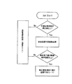
次に、上述した技術的手段の作用について、図1,2を基に説明する。
今、記録材5が定着装置4内に未進入の状態にあるとすると、このときの加熱定着部材1の表面温度は通常制御温度に保たれている。
そして、定着装置4内に記録材5が突入すると、記録材5及び記録材5上の未定着トナー像が加熱定着部材1の熱を奪い、加熱定着部材1の表面温度が低下する。このとき、温度センサ2は少なくとも記録材5の加熱定着部材1の突入時の温度と温度降下量判断時間経過後の温度とを測定し、この検知情報を制御装置3に送出する。
また、制御装置3は、温度センサ2からの検知情報に基づき、前記温度降下量判断時間内の加熱定着部材1の温度降下量を計測する。
更に、制御装置3は、温度降下量が予め決められた閾値基準温度未満か否かを判断し、温度降下量が閾値基準温度以上であれば通常制御温度に、それ以外であれば補正制御温度に切分け調整する。
すなわち、制御装置3は、図中実線で示すように温度降下量が閾値基準温度よりも小さい場合には、制御温度を補正制御温度に調整する。一方、制御装置3は、図中点線で示すように、温度降下量が閾値基準温度以上の場合には、記録材5の突入前と同じ通常制御温度を保持するように調整する。
Next, the operation of the technical means described above will be described with reference to FIGS.
Assuming that the recording material 5 is not yet in the
When the recording material 5 enters the fixing
Further, the control device 3 measures the temperature drop amount of the
Further, the control device 3 determines whether or not the temperature drop amount is lower than a predetermined threshold reference temperature. If the temperature drop amount is equal to or higher than the threshold reference temperature, the control device 3 sets the normal control temperature; Carry out the adjustment.
That is, the control device 3 adjusts the control temperature to the corrected control temperature when the temperature drop amount is smaller than the threshold reference temperature as indicated by the solid line in the figure. On the other hand, as shown by the dotted line in the figure, the control device 3 adjusts so as to maintain the same normal control temperature as that before the recording material 5 enters when the temperature drop amount is equal to or higher than the threshold reference temperature.
本発明に係る定着装置によれば、加熱定着部材の温度降下量に着目し、温度降下量が閾値基準温度に至るか否かに基づいて記録材の使用環境条件を判断し、加熱定着部材の制御温度を調整するようにしたので、普通紙や薄紙等の坪量の低い記録材を定着する際に、過剰な加熱により発生してしまうカールを有効に防止することが可能な定着装置を提供することができる。
特に、本発明では、一枚当たりのカールの曲率は小さくても、収容部での多数枚の積み重ねで収容性不良が発生することがあるため、予め決められた規定枚数以上の作像処理時に加熱定着部材の制御温度可変調整処理を行うことが有効である。
更に、記録材の搬送速度に応じて温度降下量判断時間を可変設定することにより、例えばプロセススピードが異なる場合でも、それに対応して温度降下量を正確に判断することができる。
また、このような定着装置を備えた画像形成装置によれば、複数枚印刷の出力時に記録材の積み重ねに伴って顕著に発生するカールを有効に防止することができる。
According to the fixing device of the present invention, paying attention to the temperature drop amount of the heat fixing member, the use environment condition of the recording material is determined based on whether or not the temperature drop amount reaches the threshold reference temperature, and Since the control temperature is adjusted, a fixing device that can effectively prevent curling caused by excessive heating when fixing recording materials with low basis weight such as plain paper or thin paper is provided. can do.
In particular, in the present invention, even when the curvature of a curl per sheet is small, storage failure may occur due to the stacking of a large number of sheets in the storage unit. It is effective to perform a variable control temperature adjustment process for the heat fixing member.
Furthermore, by variably setting the temperature drop amount determination time according to the conveyance speed of the recording material, for example, even when the process speed is different, the temperature drop amount can be accurately determined correspondingly.
Further, according to the image forming apparatus provided with such a fixing device, it is possible to effectively prevent curling that occurs remarkably with the stacking of recording materials when printing a plurality of sheets.
以下、添付図面に示す実施の形態に基づいてこの発明を詳細に説明する。
◎実施の形態1
図3は、本発明が適用された画像形成装置の実施の形態1を示す。同図において、本実施の形態の画像形成装置は、画像を作成するプリンタ装置10を備え、プリンタ装置10の上部に原稿を読み取るための画像読取ユニット11配設し、更に、その上方に画像読取ユニット11に原稿を送るための原稿送り装置12を配設したものである。
また、プリンタ装置10は、プリンタ筐体13の下部に用紙などのシートを供給する多段のシートトレイ51〜53を配設し、その上方にはシートトレイ51〜53からのシートにカラー画像が形成可能な作像エンジン20を設けると共に、この作像エンジン20の対向部にはシートトレイ51〜53からのシートの搬送路となるシート搬送路60と、作像エンジン20のシート搬送方向下流側にはシート上の未定着トナー像を定着する定着装置40とを配設したものである。
Hereinafter, the present invention will be described in detail based on embodiments shown in the accompanying drawings.
FIG. 3 shows
In addition, the
更に、作像エンジン20は、例えば電子写真方式を採用したものであって、イエロ(Y色)、マゼンタ(M色)、シアン(C色)及びブラック(K色)の4色の作像ユニット21(21a〜21d)を中間転写ベルト30上に並列配置させた所謂タンデム型の構成となっており、作像ユニット21(21a〜21d)にて形成された各色のトナー像を中間転写ベルト30上に順次一次転写させて多重化し、この多重化されたトナー像を二次転写装置35にてシートトレイ51〜53から搬送されたシート上に一括転写させ、定着装置40に導くようにしたものである。尚、4色の作像ユニット21の配色はこの順番に限らず、他の順番であっても差し支えない。
Further, the
本実施の形態における作像ユニット21(21a〜21d)は、各色成分トナー像を形成担持する感光体ドラム22と、この感光体ドラム22を帯電する帯電ロール等の帯電装置23、帯電された感光体ドラム22に潜像を形成するレーザ露光器24、感光体ドラム22上の静電潜像を顕像化する現像器25、感光体ドラム22上のトナー像を中間転写ベルト30上に一次転写する例えば一次転写ロールからなる一次転写装置26、感光体ドラム22上に残留した残留トナーを清掃するクリーナ27にて構成されている。尚、本実施の形態では、レーザ露光器24は、4色の作像ユニット21全体を一つのレーザ露光器24にて露光するようになっている。
The image forming unit 21 (21a to 21d) in the present embodiment includes a photosensitive drum 22 that forms and supports each color component toner image, a charging
また、中間転写ベルト30は、複数の張架ロール31〜33に張架され、例えば張架ロール31を駆動ロールとして循環搬送されるものであり、例えば二次転写ロールからなる二次転写装置35が張架ロール33をバックアップロールとして対向配置されている。更に、この中間転写ベルト30の張架ロール32と対向する位置には、中間転写ベルト30上の残留トナーを除去するベルトクリーナ36が配設されている。
Further, the
更に、シート搬送路60は次のようになっている。夫々のシートトレイ51〜53から略垂直上方に延びる垂直搬送路61と、この垂直搬送路61の下流側で、略水平に延びる主搬送路62と、主搬送路62の最下流近傍に略Y字状に下方に延びる退避搬送路63及びこの退避搬送路63の途中から略水平に延びて垂直搬送路61まで導く反転搬送路64とで構成されている。
また、シートトレイ51〜53の近傍にはシートを所定のタイミングで送り出すピックアップロール65と、シートを捌くナジャロール66とリタードロール67とを備え、最上部の1枚のシートのみが送出可能になっている。
そして、主搬送路62には、シートの位置決め規制を行うレジストロール54、中間転写ベルト30上で多重化されたトナー像を一括転写する二次転写装置35、トナー像が一括転写されたシートを搬送する搬送ベルト55、トナー像をシートに定着する定着装置40及びプリンタ筐体13の側方に設けられシートを収容する収容トレイ57にシートを排出する排出ロール56等が設けられている。
尚、これらの搬送路61〜64には、シートの搬送を確実にする搬送ロールや搬送ガイド等の搬送部材が適宜配設されている。
Further, the
In addition, a
In the
In these
また、本実施の形態の定着装置40は、図4のようになっている。同図において、定着装置40は、回転可能に配設される定着部材としての定着ロール41と、この定着ロール41に圧接し且つこの定着ロール41と共に従動回転する無端ベルト状の定着ベルト43とを備えている。
本実施の形態において、定着ロール41は、機械的強度に優れ且つ熱伝導性が良好なアルミニウム等の金属製の円筒状のコア41aと、このコア41aの表面に形成されたシリコーンゴム等の弾性層41bと、この弾性層41bの表面に被覆され、シートS上の未定着トナー像Tのオフセットを防止するために設けられた離型層41cとを備え、その内部に加熱源としてのハロゲンランプ等のヒータ42を配置したものである。
Further, the fixing
In the present embodiment, the fixing
本態様において、コア41aとしては、機械的強度と良好な熱伝導性を備えていれば特に材質は制限されず、例えばステンレス、鋼、黄銅等の金属や合金が使用される。
また、弾性層41bとしては、シリコーンゴムに限らず、耐熱性を備えていれば、例えばフッ素系ゴム等も使用でき、コア41a表面に対する成形方法も特に制限されず、注入成形法やコーティング法等が採用される。
更に、離型層41cとしては、耐熱性があり、トナーに対する適度な離型性を備えるものであればよく、例えばフッ素系ゴムやフッ素系樹脂等が使用される。
更にまた、定着ロール41内部のヒータ42としては、コア41a内部に収容できる形状、構造のものであれば特に制限されず、適宜選定して差し支えない。
In this embodiment, the material of the
Further, the
Further, the
Furthermore, the
また、定着ロール41の周囲には、定着ロール41の表面温度を計測する温度センサ49が配設され、この温度センサ49の検知情報に基づいてヒータ42の温度制御を行うことにより定着ロール41の表面温度が所定の温度に保たれるようになっている。更に、温度センサ49としては、定着ロール41の表面温度を計測できるものであれば特に制限されず、例えばサーミスタやポジスタ等の感温素子等適宜選定して差し支えない。
Further, a
一方、定着ベルト43は、単層構造であってもよいが、本実施の形態では基材表面に離型層を施した積層構造のベルトを使用している。
また、定着ベルト43の基材としては、耐熱性を有すれば、例えば熱硬化性ポリイミド、熱可塑性ポリイミド、ポリアミド、ポリアミドイミド等の樹脂基材や、ステンレス、ニッケル、銅等の金属基材が用いられる。また、離型層としては、表面に付着するトナーの剥離性が良好なものがよく、その材質としては、例えばフッ素系樹脂が用いられる。
On the other hand, the fixing
Further, as a base material of the fixing
更に、定着ベルト43は、張架ロールなどを持たず、定着ロール41に対向する定着ベルト43の内側に耐熱性を有するシリコーンゴム等の弾性材料によって形成される加圧パッド46を配設して支持するようにしたものである。そして、当該加圧パッド46にて定着ベルト43を定着ロール41に向けて押圧することにより両者間に接触ニップ域を形成し、この接触ニップ域に未定着トナー像Tが転写されたシートSを通過させることでこの未定着トナー像Tを加熱・加圧定着させるようになっている。
また、この加圧パッド46は、断面略凹状の保持部材48に嵌合するように配設される一方、定着ベルト43側には表面に定着ベルト43との摩擦抵抗を小さく維持し、定着ベルト43の回転を一層スムーズにさせるために、例えばフッ素系樹脂シートからなる低摩擦シート46aを設けたものである。
Further, the fixing
Further, the
更にまた、保持部材48の加圧パッド46よりも下流側には、シートSが剥離可能な剥離ニップ域を形成する剥離ニップ部材47が収容されている。この剥離ニップ部材47は、例えばアルミニウム、ステンレス、鋼、銅、黄銅等の金属や合金からなる高剛性の材料によって構成されている。
また、保持部材48は、その下部側に設けられた支持部材44にて支持され、更に、この支持部材44の下部側には、断面略円弧面のベルト走行ガイド45が取り付けられている。そして、保持部材48には図示しないバネが取り付けられており、これにより、当該保持部材48に嵌合する加圧パッド46を介して定着ベルト43が定着ロール41側に向かって付勢するようになっている。
Furthermore, a peeling nip
The holding
また、本実施の形態に係る制御系について、図5に示す。同図に示すように、制御装置80には、ユーザ入力150、温度センサ49、画像密度情報200、環境センサ300等の各情報が入力可能に接続されている。尚、各種装置等の詳細については後述する。
一方、制御装置80には制御信号が定着装置40へ送出可能に接続されている。
更に、制御装置80は、マイクロコンピュータシステムからなり、制御部としてのCPU、ROM、RAMなどを有しROM内には処理プログラムなどが予め格納されており、CPUは各プログラムを実行し、各入力情報に基づいて、温度降下量判断時間、閾値基準温度、補正制御温度及び通常制御温度を可変設定するものである。
FIG. 5 shows a control system according to the present embodiment. As shown in the figure, the
On the other hand, the
Further, the
本実施の形態において、ユーザ入力150としては、例えば、図6(a),(b)に示すように、ユーザインタフェース100の画面に示される選択ボタンが挙げられる。
図6(a)にはユーザインタフェース100の通常画面を示す。同図に示すように、ユーザインタフェース100の通常画面には「基本コピー(101)」、「画質調整(102)」、「読み取り方法(103)」、「出力形式(104)」、「ジョブ編集(105)」の各設定が変更可能に表示されおり、今、「基本コピー(101)」の画面が示されている。
この画面では、「倍率選択(111)」、「用紙選択(112)」、「カラーモード(113)」の各設定についてボタン表示されており、今、「倍率選択(111)」が「100%(121)」に、「用紙選択(112)」が「A4(122)」に、「カラーモード(113)」が「白黒(123)」に選択されている。また、例えば、「セット(107)」が50に選定されており、作像処理枚数が50枚に設定されている。
この選択された情報が、ユーザ入力情報として、制御装置80へ送出されるようになっている。
In the present embodiment, examples of the
FIG. 6A shows a normal screen of the
In this screen, buttons for the settings of “magnification selection (111)”, “paper selection (112)”, and “color mode (113)” are displayed, and “magnification selection (111)” is now “100%”. In (121), “paper selection (112)” is selected as “A4 (122)”, and “color mode (113)” is selected as “monochrome (123)”. Further, for example, “Set (107)” is selected as 50, and the number of image forming processes is set as 50.
The selected information is sent to the
更に、「用紙選択(112)」の「他のトレイ(124)」から図示外の「トレイ5」を選択すると図6(b)の画面に切り替わり、「用紙サイズ(131)」と「用紙種類(132)」が選定可能にボタン表示される。
この画面において、「用紙サイズ(131)」の設定としては「自動サイズ検知(141)」、「定形サイズ(142)」、「非定形サイズ(143)」がボタン表示されており、ボタンを選択すると、所定の用紙サイズが選定される。
また、同様に、「用紙種類(132)」の設定には「普通紙(145)」、「再生紙(146)」、「厚紙1(147)」、「厚紙2(148)」、「OHPフィルム(149)」がボタン表示されており、選択するボタンを押すと、所定の紙種に設定されると共に、この入力された紙種情報が制御装置80に送出されるようになっている。
Further, when “tray 5” (not shown) is selected from “other tray (124)” of “paper selection (112)”, the screen is switched to the screen of FIG. 6B, and “paper size (131)” and “paper type” are displayed. (132) "is displayed as a button so that selection is possible.
On this screen, “automatic size detection (141)”, “standard size (142)”, and “non-standard size (143)” are displayed as buttons for setting “paper size (131)”. Then, a predetermined paper size is selected.
Similarly, the setting of “paper type (132)” includes “plain paper (145)”, “recycled paper (146)”, “thick paper 1 (147)”, “thick paper 2 (148)”, “OHP”. “Film (149)” is displayed as a button, and when a button to be selected is pressed, a predetermined paper type is set and the input paper type information is sent to the
次に、本実施の形態に係る画像形成装置の作像プロセスについて説明する。今、図示外のスタートボタンが押されると、周知の電子写真プロセスにより例えばK色の作像ユニット21dにて感光体ドラム22の表面にトナー像が形成されると、このトナー像は一次転写装置26により感光体ドラム22と略同速度で移動する中間転写ベルト30上に転写される(図3参照)。尚、フルカラー画像を作像する場合は各色の感光体ドラム22の表面にトナー像を形成すればよい。
また、シート搬送系は、シートトレイ51からシートを1枚送り出し、垂直搬送路61のリタードロール67を介して主搬送路62のレジストロール54まで搬送すると、このレジストロール54にて一旦停止させる。この後、シートは、シート上への画像書き込みタイミングに合わせて二次転写装置35に搬送され、中間転写ベルト30上のモノクロトナー像が当該シート上に転写される。そして、このシートは、搬送ベルト55を通り、定着装置40に搬送され、定着装置40にてシート表面の未定着トナー像が定着された後に、収容トレイ57に排出される。
また、両面画像形成モードの場合、定着後のシートは、退避搬送路63に搬送され、反転搬送路64にて反転した後、再度主搬送路62のレジストロール54まで搬送される。そして、当該シートは、レジストロール54にて一旦停止してから、二次転写装置35にてシートのもう一方の面に中間転写ベルト30上のトナー像が転写され、定着装置40にてトナー定着が行われた後、収容トレイ57に排出される。
Next, an image forming process of the image forming apparatus according to the present embodiment will be described. When a start button (not shown) is pressed, a toner image is formed on the surface of the photosensitive drum 22 by, for example, a K-color
Further, when the sheet conveying system feeds one sheet from the
In the double-sided image forming mode, the fixed sheet is conveyed to the
このような作像プロセスにおいて、定着装置40の温度制御プロセスについて、図7を基に説明する。
本実施の形態において、制御装置80には、ユーザ入力150からの情報として、作像処理枚数に50枚、紙種に普通紙、作像条件に白黒作像モード、画像形成条件に片面画像形成モードが入力されている(図5参照)。また、制御装置80は、作像処理枚数が例えば50枚以上の場合に、定着ロール41の制御温度可変調整処理を行うようになっており、前記入力情報に基づいて作動するようになっている。尚、制御装置80が作動する作像処理枚数の規定値は、例として50枚としているが、これに限られるものではなく、紙種や環境条件等に応じて適宜選定して差し支えない。
In such an image forming process, a temperature control process of the fixing
In the present embodiment, the
そして、今、シートが定着装置40内に未進入の状態にあるとすると、このときの定着ロール41の表面温度は通常制御温度に保たれている(図8参照)。
ここで、制御装置80は、シートの定着装置40への突入時から所定の時間を温度降下量判断時間として予め設定する。
そして、定着ロール41内にシートが突入すると、シート及びシート上のトナー像が定着ロール41の熱を奪い、定着ロール41の表面温度は低下する。このとき、温度センサ49は少なくともシートの定着ロール41突入時の温度と所定の時間経過後の温度とを測定し、この検知情報を制御装置80に送出する。
また、制御装置80は、温度センサ49からの検知情報に基づき、温度降下量判断時間内の定着ロール41表面の温度降下量を計測する。
If it is assumed that the sheet has not yet entered the fixing
Here, the
When the sheet enters the fixing
Further, the
更に、制御装置80は、温度降下量が予め決められた閾値基準温度未満か否かを判断し、温度降下量が閾値基準温度以上であれば通常制御温度に、それ以外であれば補正制御温度に切分け調整する。
すなわち、図8中実線に示すように、制御装置80は、温度降下量が閾値基準温度よりも小さい場合に、制御温度を補正制御温度に調整する。一方、図中点線で示すように、温度降下量が閾値基準温度以上の場合に、制御装置80は通常制御温度を保持するように調整する。
また、本実施の形態においては、制御装置80が温度降下量を測定し、閾値基準温度と比較して制御温度の変更の可否を制御しているが、このような態様に限られず、予め決められた通常制御温度から閾値基準温度を差し引いた温度を切替判別温度として設定しておき、温度降下量判断時間経過後の温度が前記切替判別温度以上か否かによって制御温度を切分け調整するようにしてもよい。すなわち、図中実線で示すように、判断時間経過後の定着ロール41の表面温度が切替判別温度よりも高い場合に制御温度を補正制御温度に調整し、一方、図中点線で示すように、定着ロール41の表面温度が切替判別温度以下のときに通常制御温度を保つように調整することもできる。
Further, the
That is, as shown by the solid line in FIG. 8, the
In this embodiment, the
このような作像プロセスにおいて、制御温度可変調整処理として、紙種、画像密度、環境条件、白黒/カラーの作像条件、両面/片面の画像形成条件等に応じて、温度降下量判断時間、閾値基準温度、補正制御温度及び通常制御温度の可変設定条件のうち少なくとも一つを可変にすれば、定着ロール41の表面温度をより最適にすることができる(図9参照)。
すなわち、作像処理枚数が規定枚数以上であれば、紙種、画像密度、環境条件、白黒/カラーの作像条件、両面/片面の画像形成条件等に応じて、可変設定された温度降下量判断時間内の温度降下量に基づいて、可変設定された補正制御温度または可変設定された通常制御温度に切分け調整するようにしたものである。より具体的には、制御装置80は、温度降下量が可変設定された閾値基準温度未満か否かを判断し、温度降下量が閾値基準温度以上のときに通常制御温度に、それ以外の時に補正制御温度に切分け調整することが可能である。尚、ここでは、温度降下量判断時間、閾値基準温度、補正制御温度及び通常制御温度の可変設定条件のうち全てを可変設定した場合について説明したが、これに限られるものではなく、使用環境条件に応じて夫々適宜可変設定すればよい。
尚、各条件に応じて、可変設定条件を可変にした態様の詳細については後述する実施例で説明する。
In such an image forming process, as the control temperature variable adjustment process, the temperature drop amount judgment time, depending on the paper type, image density, environmental conditions, black / white / color image forming conditions, double-sided / single-sided image forming conditions, If at least one of the variable setting conditions of the threshold reference temperature, the correction control temperature, and the normal control temperature is made variable, the surface temperature of the fixing
That is, if the number of image forming processes is equal to or greater than the specified number, the temperature drop amount variably set according to the paper type, image density, environmental conditions, black / white / color image forming conditions, double-sided / single-sided image forming conditions, etc. Based on the temperature drop amount within the determination time, the adjustment control temperature is variably set or the normal control temperature is variably set. More specifically, the
Note that details of the mode in which the variable setting condition is made variable according to each condition will be described in an embodiment described later.
更に、このように制御温度が可変設定され且つ定着処理が行われている最中に、トレイ変更による紙種変更が行われたり作像条件変更が行われたとすると、制御装置80は、その紙種に対応した温度降下量判断時間、閾値基準温度、補正制御温度及び通常制御温度の少なくとも一つを再度設定し直し、再度適切な制御温度に切分け調整することができる。
本実施の形態によれば、普通紙や薄紙等の坪量の低い用紙を定着する際に、過剰な加熱により発生してしまうカールを有効に防止することが可能な定着装置を提供することができる。
更に、シート毎の個別の使用環境条件に応じて制御装置80の可変設定条件を可変設定すれば定着ロール41の温度をより的確な温度制御を行うことができる。
Further, if the paper type is changed by changing the tray or the image forming condition is changed while the control temperature is variably set and the fixing process is being performed in this way, the
According to the present embodiment, it is possible to provide a fixing device that can effectively prevent curling that occurs due to excessive heating when fixing a low basis weight paper such as plain paper or thin paper. it can.
Furthermore, if the variable setting condition of the
◎実施例1
実施例1は、実施の形態1に係る画像形成装置と同様のものを用い、紙種に応じて温度降下量判断時間を可変にし、定着ロール41の温度制御を行ったものである(図10参照)。
本実施例における主な設定及び条件は、以下のとおりである。
・紙種:普通紙、厚紙
・温度降下量判断時間:普通紙 4秒、厚紙 6秒
すなわち、ユーザ入力情報としてユーザインタフェース100の「用紙種類(132)」が「普通紙(145)」または「厚紙1(147)」に選定されているとすると、この入力情報に基づいて温度降下量判断時間が可変設定される(図6(b)参照)。
Example 1
In Example 1, the same image forming apparatus as that of the first embodiment is used, and the temperature drop determination time is made variable according to the paper type, and the temperature of the fixing
Main settings and conditions in the present embodiment are as follows.
Paper type: plain paper, cardboard, temperature drop amount judgment time:
今、ユーザ入力150には、作像処理枚数として50枚、紙種として普通紙または厚紙、作像条件として白黒作像モード、画像形成条件として片面画像形成モードが選択されている。このとき、制御装置80は、温度降下量判断時間を、普通紙の場合4秒に、厚紙の場合6秒に可変設定し、この温度降下量判断時間内の温度降下量が閾値基準温度未満か否かに基づいて制御温度に切分け調整する。
すなわち、図10に示すように、普通紙、厚紙夫々の態様において、温度降下量判断時間経過後の定着ロール41の温度降下量が閾値基準温度未満であれば、制御温度が補正制御温度に切分け調整される。尚、温度降下量が閾値基準温度以上であれば、通常制御温度に切分け調整される。
このように紙種により温度降下量判断時間を可変設定することにより、厚紙に比べてプロセススピードの速い普通紙を用いた態様において、初期に排出される用紙の枚数を低減させることができ、スタック時のカールを抑えることができる。
Now, as the
That is, as shown in FIG. 10, in the case of each of plain paper and cardboard, if the temperature drop amount of the fixing
Thus, by variably setting the temperature drop amount judgment time depending on the paper type, the number of sheets discharged at the initial stage can be reduced in the mode using plain paper whose process speed is faster than that of thick paper, and the stack Curling at the time can be suppressed.
◎実施例2
実施例2は、実施例1において、制御装置80が用紙の種類に応じて閾値基準温度及び補正制御温度を夫々可変設定するようにしたものであり、より適正な温度制御を行うことができる(図11参照)。
本実施例における主な設定及び条件は、以下のとおりである。
・紙種:普通紙、厚紙
・温度降下量判断時間:普通紙 4秒、厚紙 6秒
・閾値基準温度:普通紙 5℃、厚紙 7℃
・補正制御温度:普通紙 −10℃、厚紙 −7℃
尚、通常制御温度を188℃に設定して表記すると共に、同図において、閾値基準温度のほかに閾値基準温度を絶対温度として表した切替判別温度も表記している。
本実施例において、用紙の坪量と用紙の熱吸収性とは比例関係にあるため、同じプロセススピード及び生産性であれば温度降下量は坪量の大きい厚紙の方が熱吸収量も大きくなる。したがって、坪量の低い普通紙などは、定着ロール41の温度降下量が小さいため、閾値基準温度を小さく設定すればよい。また、普通紙は最低定着温度も低いため補正制御温度も低く設定すればよい。また、通常制御温度は、普通紙の場合に低く設定するなど、適宜可変設定して差し支えない。
Example 2
In the second embodiment, the
Main settings and conditions in the present embodiment are as follows.
-Paper type: Plain paper, thick paper-Temperature drop judgment time:
・ Correction control temperature: Plain paper -10 ℃, thick paper -7 ℃
In addition, the normal control temperature is set to 188 ° C. and expressed, and in the same figure, the switching determination temperature in which the threshold reference temperature is expressed as an absolute temperature is also described in addition to the threshold reference temperature.
In this embodiment, the basis weight of the paper and the heat absorbability of the paper are in a proportional relationship. Therefore, if the process speed and productivity are the same, the amount of temperature drop is larger for thick paper with a larger basis weight. . Accordingly, since the temperature drop of the fixing
本態様において、制御装置80は、普通紙の場合、閾値基準温度を5℃、補正制御温度を通常制御温度から10℃低い温度に設定し、厚紙の場合、閾値基準温度を7℃、補正制御温度を通常制御温度から7℃低い温度に設定されている。
このような設定下において、定着ロール41の制御温度は、図11に示すように、普通紙、厚紙夫々の態様において、温度降下量判断時間経過後の温度降下量が夫々閾値基準温度未満であれば、制御温度が補正制御温度に切分け調整される。尚、温度降下量が閾値基準温度以上であれば、通常制御温度に切分け調整される。
このように紙種により温度降下量判断時間、閾値基準温度及び補正制御温度を可変設定することにより、適正な温度制御を行うことができる。
In this embodiment, the
Under such a setting, as shown in FIG. 11, the control temperature of the fixing
In this manner, by appropriately setting the temperature drop amount determination time, the threshold reference temperature, and the correction control temperature depending on the paper type, appropriate temperature control can be performed.
◎実施例3
実施例3は、実施の形態1に係る画像形成装置と同様のものを用い、白黒作像モードまたはカラー作像モードの作像条件に応じて温度降下量判断時間を可変にし、定着ロール41の温度制御を行ったものである(図12参照)。
本実施例における主な設定及び条件は、以下のとおりである。
・作像条件:白黒作像モード、カラー作像モード
・温度降下量判断時間:白黒作像モード2秒、カラー作像モード4秒
すなわち、ユーザ入力情報としてユーザインタフェース100の「カラーモード(113)」が「白黒(123)」または「フルカラー(125)」に選定されているとすると、この入力情報に基づいて温度降下量判断時間は可変設定される(図6(a)参照)。
Example 3
In Example 3, the same image forming apparatus as that of the first embodiment is used, the temperature drop amount determination time is made variable according to the image forming conditions in the monochrome image forming mode or the color image forming mode, and the fixing
Main settings and conditions in the present embodiment are as follows.
Image forming conditions: black and white image forming mode, color image forming modeTemperature drop amount determination time: black and white
今、ユーザ入力150には、作像処理枚数として50枚、紙種として普通紙、作像条件として白黒作像モードまたはカラー作像モード、画像形成条件として片面画像形成モードが選択されている。このとき、制御装置80は、温度降下量判断時間を、白黒作像モードの場合2秒に、カラー作像モードの場合4秒に可変設定し、この温度降下量判断時間内の温度降下量が閾値基準温度未満か否かに基づいて制御温度を切分け調整するものである。
すなわち、図12に示すように、白黒作像モード、カラー作像モード夫々の態様において、温度降下量判断時間経過後の定着ロール41の温度降下量が閾値基準温度未満であれば、制御温度が補正制御温度に切分け調整される。
このように作像条件により温度降下量判断時間を可変設定することにより、カラー作像モードに比べてプロセススピードの速い白黒作像モードにおいて、初期に排出される用紙の枚数を低減させることができ、スタック時のカールを抑えることができる。
In the
That is, as shown in FIG. 12, in each of the monochrome image forming mode and the color image forming mode, if the temperature drop amount of the fixing
By variably setting the temperature drop amount judgment time according to the image forming conditions in this way, the number of sheets discharged in the initial stage can be reduced in the black and white image forming mode, which has a faster process speed than the color image forming mode. , Curling during stacking can be suppressed.
◎実施例4
実施例4は、実施例3において、制御装置80が白黒作像モードまたはカラー作像モードの作像条件に応じて閾値基準温度及び補正制御温度を夫々可変設定したものであり、より適正な温度制御を行うことができる(図13参照)。
本実施例における主な設定及び条件は、以下のとおりである。
・作像条件:白黒作像モード、カラー作像モード
・温度降下量判断時間:白黒作像モード 2秒、カラー作像モード 4秒
・閾値基準温度:白黒作像モード 5℃、カラー作像モード 3℃
・補正制御温度:白黒作像モード −10℃、カラー作像モード −5℃
この場合、一般に、白黒作像モードでは、カラー作像モードに比べてプロセススピードが速く、その分、温度降下量が大きいため、閾値基準温度が大きく設定されている。また、フルカラー作像モードでは、白黒作像モードに比べて画像密度が高く、トナーの発色性を得るために、補正制御温度が高く設定されている。また、通常制御温度は、白黒作像モードにおいて低く設定するなど、適宜可変設定して差し支えない。
Example 4
In the fourth embodiment, in the third embodiment, the
Main settings and conditions in the present embodiment are as follows.
・ Image creation conditions: monochrome imaging mode, color imaging mode ・ Temperature drop amount judgment time:
-Correction control temperature: black and white image formation mode -10 ° C, color image formation mode -5 ° C
In this case, generally, in the black and white image forming mode, the process speed is faster than that in the color image forming mode, and the amount of temperature drop is correspondingly large. Therefore, the threshold reference temperature is set to be large. In the full-color image forming mode, the image density is higher than that in the black and white image forming mode, and the correction control temperature is set high in order to obtain the color development property of the toner. In addition, the normal control temperature may be appropriately variably set such as being set low in the monochrome image forming mode.
本態様において、制御装置80は、白黒作像モードの場合、閾値基準温度を5℃、補正制御温度を通常制御温度から10℃低い温度に設定し、カラー作像モードの場合、閾値基準温度を3℃、補正制御温度を通常制御温度から5℃低い温度に設定されている。
このような設定下において、定着ロール41の制御温度は、図13に示すように、白黒作像モード、カラー作像モード夫々の態様において、温度降下量判断時間経過後の温度降下量が夫々閾値基準温度未満であれば、制御温度が補正制御温度に切分け調整される。尚、温度降下量が閾値基準温度以上であれば、通常制御温度に切分け調整される。
このように作像条件により温度降下量判断時間、閾値基準温度及び補正制御温度を可変設定することにより、適正な温度制御を行うことができる。
In this aspect, the
Under such a setting, as shown in FIG. 13, the control temperature of the fixing
As described above, by appropriately setting the temperature drop amount determination time, the threshold reference temperature, and the correction control temperature according to the image forming conditions, appropriate temperature control can be performed.
◎実施例5
実施例5は、実施例4において、制御装置80が画像密度に応じて閾値基準温度及び補正制御温度を夫々可変設定するものであり、より適正な温度制御を行うことができる(図14参照)。すなわち、単色作像モードと複数色作像モードとにおいて、用紙の種類及びプロセススピードが同等であれば、温度降下量が画像密度に依存するため、本態様が有効である。
本実施例において、制御装置80は、デジタル画像信号に変換された画像読み取り信号から画像密度情報200を取り込み、制御温度の切分け調整を行うようになっている(図5参照)。
本実施例における主な設定及び条件は、以下のとおりである。
・画像密度条件:低画像密度、高画像密度
・温度降下量判断時間:低画像密度 2秒、高画像密度 4秒
・閾値基準温度:低画像密度 5℃、高画像密度 6℃
・補正制御温度:低画像密度 −10℃、高画像密度 −8℃
Example 5
In the fifth embodiment, in the fourth embodiment, the
In the present embodiment, the
Main settings and conditions in the present embodiment are as follows.
・ Image density conditions: Low image density, high image density ・ Temperature drop amount judgment time:
Correction control temperature: Low image density −10 ° C., High image density −8 ° C.
この場合、例えば、低画像密度では、高画像密度に比べて温度降下量が小さく且つ最低定着温度も低いので、高画像密度に比べて閾値基準温度を小さく且つ補正制御温度を低く設定されている。また、通常制御温度は、低画像密度において低く設定するなど、適宜可変設定して差し支えない。
すなわち、図14に示すように、低画像密度、高画像密度夫々の態様において、温度降下量判断時間経過後の定着ロール41の温度降下量が夫々閾値基準温度未満であれば、補正制御温度に切分け調整される。尚、温度降下量が閾値基準温度以上であれば、通常制御温度に切分け調整される。
このように、画像密度により、温度降下量判断時間、閾値基準温度及び補正制御温度を可変設定することにより、適正な温度制御を行うことができる。
In this case, for example, at a low image density, the amount of temperature drop is smaller and the minimum fixing temperature is lower than at a high image density, so the threshold reference temperature is set lower and the correction control temperature is set lower than at a high image density. . In addition, the normal control temperature may be appropriately variably set, such as being set low at a low image density.
That is, as shown in FIG. 14, in each of the low image density and the high image density, if the temperature drop amount of the fixing
Thus, appropriate temperature control can be performed by variably setting the temperature drop amount determination time, the threshold reference temperature, and the correction control temperature according to the image density.
◎実施例6
実施例6は、実施の形態1に係る画像形成装置と同様のものを用い、片面画像形成モードまたは両面画像形成モードの画像形成条件に応じて温度降下量判断時間を可変設定し、定着ロール41の温度制御を行うようにしたものである(図15参照)。
本実施例における主な設定及び条件は、以下のとおりである。
・画像形成条件:片面画像形成モード、両面画像形成モード
・温度降下量判断時間:片面画像形成モード 4秒、両面画像形成モード 4秒
・閾値基準温度:片面画像形成モード 5℃、両面画像形成モード 3℃
・補正制御温度:片面画像形成モード −10℃、両面画像形成モード −6℃
すなわち、ユーザ入力情報としてユーザインタフェース100の「読み取り方法(103)」が選択され、図示外の「片面コピー」または「両面コピー」に選定されているとすると、この入力情報に基づいて温度降下量判断時間が可変設定される(図6(a)参照)。
Example 6
In Example 6, the same image forming apparatus as that of the first embodiment is used, the temperature drop amount determination time is variably set according to the image forming conditions in the single-sided image forming mode or the double-sided image forming mode, and the fixing
Main settings and conditions in the present embodiment are as follows.
-Image formation conditions: single-sided image formation mode, double-sided image formation mode-Temperature drop judgment time: single-sided
Correction control temperature: single-sided image formation mode −10 ° C., double-sided image formation mode −6 ° C.
That is, if “reading method (103)” of the
今、ユーザ入力150には、作像処理枚数として50枚、紙種として普通紙、作像条件として白黒作像モード、画像形成条件として片面画像形成モードまたは両面画像形成モードが選択されている。このとき、制御装置80は、両面画像形成モードの場合、閾値基準温度を3℃、補正制御温度を通常制御温度から6℃低い温度に設定し、片面画像形成モードの場合、閾値基準温度を5℃、補正制御温度を通常制御温度から10℃低い温度に設定し、温度降下量判断時間内の温度降下量が閾値基準温度未満か否かに基づいて制御温度に切分け調整する。
このような設定下において、定着ロール41の制御温度は、図15に示すように、片面画像形成モード、両面画像形成モード夫々の態様において、温度降下量判断時間経過後の温度降下量が閾値基準温度未満であれば、制御温度が補正制御温度に切分け調整される。尚、温度降下量が閾値基準温度以上であれば、通常制御温度に切分け調整される。
本態様によれば、両面画像形成モード時は、1面目の定着でカールが発生しても2面目の定着で反対側の形状にカールが補正されるため、片面画像形成モードに比べて閾値基準温度を小さく且つ補正制御温度を高く設定ができる。
このように画像形成モードにより閾値基準温度及び補正制御温度を可変設定することにより、適正な温度制御を行うことができる。
In the
Under such a setting, the control temperature of the fixing
According to this aspect, in the double-sided image forming mode, even if the curling occurs in the fixing on the first side, the curling is corrected to the opposite shape by the fixing on the second side. The temperature can be set low and the correction control temperature can be set high.
As described above, by appropriately setting the threshold reference temperature and the correction control temperature according to the image forming mode, appropriate temperature control can be performed.
◎実施例7
実施例7は、実施の形態1に係る画像形成装置と同様のものを用いると共に、画像形成装置内に少なくとも温度が検知可能な環境センサ300を配設し、この検知情報に基づいて制御装置80が通常制御温度を補正するようにしたものであり、より適正な温度制御を行うことができる(図3,5参照)。
本実施例における環境条件及び制御温度は以下のとおりである。
・環境条件:低温(室温10℃)、通常(室温20℃以上25℃未満)、高温(室温30℃)
・通常制御温度:188℃
・低温時の通常制御温度:通常制御温度 188+10℃=198℃
・高温時の通常制御温度:通常制御温度 188−5℃=183℃
すなわち、図16に示すように、通常定着時(例えば室温20℃以上25℃未満)の室温をα、通常温度時の通常制御温度188℃をβ、室温20℃を基準とした際の温度差をtとすると、(室温,基準温度)は、室温が20℃未満であれば(α−t℃,β+t℃)とし、室温がαより1℃低くなるにつれて通常制御温度をβよりも1℃上昇するように調整される。したがって、低温(室温10℃)であれば、(α−10℃,β+10℃)となり、通常制御温度は通常時よりも10℃高い198℃に調整される。
Example 7
In Example 7, the same image forming apparatus as that of the first embodiment is used, and an
The environmental conditions and control temperatures in this example are as follows.
-Environmental conditions: low temperature (
・ Normal control temperature: 188 ℃
・ Normal control temperature at low temperature: Normal control temperature 188 + 10 ° C = 198 ° C
-Normal control temperature at high temperature: Normal control temperature 188-5 ° C = 183 ° C
That is, as shown in FIG. 16, the room temperature during normal fixing (for example,
一方、室温が25℃以上であれば、上述した(室温,基準温度)は、室温20℃を基準にして(α+t℃,β−t/2℃)に設定され、室温がαより1℃高くなるにつれて通常制御温度をβよりも0.5℃下降するように調整される。したがって、室温30℃であれば、(α+10℃,β−5℃)となり、通常制御温度は通常時よりも5℃低い183℃に調整される。
このように環境により通常制御温度を補正し、この温度を基準にして閾値基準温度や補正制御温度を変更するようにすれば、環境条件に応じた温度調整を行うことができる。
On the other hand, if the room temperature is 25 ° C. or higher, the above (room temperature, reference temperature) is set to (α + t ° C., β−t / 2 ° C.) based on the room temperature of 20 ° C., and the room temperature is 1 ° C. higher than α. As a result, the control temperature is usually adjusted to be lowered by 0.5 ° C. from β. Therefore, if the room temperature is 30 ° C., (α + 10 ° C., β−5 ° C.) is obtained, and the normal control temperature is adjusted to 183 ° C., which is 5 ° C. lower than normal.
As described above, if the normal control temperature is corrected according to the environment and the threshold reference temperature and the corrected control temperature are changed based on this temperature, the temperature can be adjusted according to the environmental conditions.
1…加熱定着部材,2…温度センサ,3…制御装置,3a…判断要素,3b…制御温度可変要素,4…定着装置,5…記録材
DESCRIPTION OF
Claims (9)
前記加熱定着部材の表面温度を検知する温度センサと、
前記温度センサの検知情報に基づいて加熱定着部材を予め決められた制御温度に制御する制御装置とを備えた定着装置であって、
前記制御装置は、予め決められた規定枚数以上の作像処理時に加熱定着部材に対して制御温度可変調整処理を実行することを決定する決定要素と、
前記決定要素にて前記加熱定着部材に対して制御温度可変調整処理を実行することが決定されたときに、記録材の搬送速度に応じて当該記録材が定着装置に突入してから予め決められた時間経過するまでの温度降下量判断時間を前記記録材の搬送速度につき速い方が遅い方に比べて短くなるように可変設定し、前記温度センサからの温度情報に基づいて前記温度降下量判断時間までの加熱定着部材の温度降下量を判断する判断要素と、
定着可能な温度範囲内で加熱定着部材の通常制御温度及びこの通常制御温度より低い補正制御温度を有し、前記判断要素により判断した温度降下量が予め決められた閾値基準温度未満か否かを判断し、温度降下量が閾値基準温度以上であれば通常制御温度に、それ以外であれば補正制御温度に切分け調整する制御温度可変要素とを備えたことを特徴とする定着装置。 A heating and fixing member for heating and fixing an unfixed image formed on a recording material whose surface is heated by a heat source to come into contact with the recording material and whose conveyance speed can be changed ;
A temperature sensor for detecting a surface temperature of the heat fixing member;
A fixing device including a control device that controls the heating fixing member to a predetermined control temperature based on detection information of the temperature sensor ,
The control device determines a control temperature variable adjustment process for the heat fixing member at the time of an image forming process of a predetermined number or more, and a determining element;
When it is determined by the determining element that the control temperature variable adjustment process is performed on the heat fixing member, the recording material is determined in advance after entering the fixing device according to the conveyance speed of the recording material. and variably set to be shorter than the amount of temperature drop determination time to the elapsed time towards faster slower per transport speed of the recording material, the amount of temperature drop determined based on the temperature information from said temperature sensor A judgment element for judging the amount of temperature drop of the heat fixing member up to the time ,
It has a normal control temperature of the heat-fixing member and a correction control temperature lower than the normal control temperature within the fixable temperature range, and whether or not the temperature drop determined by the determination element is less than a predetermined threshold reference temperature. A fixing device comprising: a control temperature variable element that determines and adjusts to a normal control temperature if the temperature drop amount is equal to or higher than a threshold reference temperature, and to a correction control temperature otherwise.
前記制御温度可変要素は、閾値基準温度、通常制御温度及び補正制御温度の少なくともいずれか一つを可変設定することを特徴とする定着装置。 The fixing device according to claim 1.
The fixing device according to claim 1, wherein the control temperature variable element variably sets at least one of a threshold reference temperature, a normal control temperature, and a correction control temperature.
前記判断要素は、記録材の種類に応じて温度降下量判断時間を個別の時間に可変設定することを特徴とする定着装置。 The fixing device according to claim 1 .
The fixing device is characterized in that the determination element variably sets a temperature drop amount determination time to an individual time according to the type of recording material.
前記判断要素は、複数色作像モードまたは単色作像モードの作像条件に応じて温度降下量判断時間を個別の時間に可変設定することを特徴とする定着装置。 The fixing device according to claim 1 .
The fixing device is characterized in that the temperature drop amount determination time is variably set to an individual time according to the image forming condition of the multi-color image forming mode or the single color image forming mode.
前記制御温度可変要素は、記録材の種類に応じて、閾値基準温度、通常制御温度及び補正制御温度の少なくともいずれか一つを可変設定することを特徴とする定着装置。 The fixing device according to claim 2 .
The fixing device according to claim 1, wherein the control temperature variable element variably sets at least one of a threshold reference temperature, a normal control temperature, and a correction control temperature according to the type of the recording material.
前記制御温度可変要素は、作像条件に応じて、閾値基準温度、通常制御温度及び補正制御温度の少なくともいずれか一つを可変設定することを特徴とする定着装置。 The fixing device according to claim 2 .
The fixing device according to claim 1, wherein the control temperature variable element variably sets at least one of a threshold reference temperature, a normal control temperature, and a correction control temperature according to an image forming condition.
前記制御装置は、定着処理中に記録材または作像条件の変更情報を受け付けた条件下では、前記判断要素及び前記制御温度可変要素の可変設定条件の少なくとも一つを可変設定することを特徴とする定着装置。 The fixing device according to claim 1 or 2 ,
The controller, under the conditions of accepting the change information of the recording material or the image forming condition during the fixing process, and characterized in that at least one variable setting condition of the decision element and the control temperature variables variably sets Fixing device to do.
前記制御装置は、定着装置の周辺に配された環境センサの環境情報に基づいて、前記判断要素及び前記制御温度可変要素の可変設定条件の少なくとも一つを可変設定することを特徴とする定着装置。 The fixing device according to claim 1 or 2 ,
Wherein the control device, based on the environmental information environmental sensors arranged around the fixing device, the decision element and the fixing device, characterized by variably setting at least one variable setting condition of the control temperature variables .
Priority Applications (1)
| Application Number | Priority Date | Filing Date | Title |
|---|---|---|---|
| JP2006000912A JP4899480B2 (en) | 2006-01-05 | 2006-01-05 | Fixing device and image forming apparatus using the same |
Applications Claiming Priority (1)
| Application Number | Priority Date | Filing Date | Title |
|---|---|---|---|
| JP2006000912A JP4899480B2 (en) | 2006-01-05 | 2006-01-05 | Fixing device and image forming apparatus using the same |
Publications (2)
| Publication Number | Publication Date |
|---|---|
| JP2007183365A JP2007183365A (en) | 2007-07-19 |
| JP4899480B2 true JP4899480B2 (en) | 2012-03-21 |
Family
ID=38339538
Family Applications (1)
| Application Number | Title | Priority Date | Filing Date |
|---|---|---|---|
| JP2006000912A Expired - Fee Related JP4899480B2 (en) | 2006-01-05 | 2006-01-05 | Fixing device and image forming apparatus using the same |
Country Status (1)
| Country | Link |
|---|---|
| JP (1) | JP4899480B2 (en) |
Families Citing this family (2)
| Publication number | Priority date | Publication date | Assignee | Title |
|---|---|---|---|---|
| US7831165B2 (en) | 2008-03-27 | 2010-11-09 | Seiko Epson Corporation | Fixing device and image forming apparatus equipped with the fixing device |
| JP5640404B2 (en) | 2010-03-10 | 2014-12-17 | 株式会社リコー | Fixing apparatus, image forming apparatus, and fixing condition control method |
Family Cites Families (3)
| Publication number | Priority date | Publication date | Assignee | Title |
|---|---|---|---|---|
| JPH0736233A (en) * | 1993-07-16 | 1995-02-07 | Canon Inc | Image forming device |
| JP3224169B2 (en) * | 1993-10-26 | 2001-10-29 | 京セラミタ株式会社 | Paper thickness detecting device, temperature control device of fixing device including the same, and image forming apparatus |
| JPH1165362A (en) * | 1997-08-25 | 1999-03-05 | Ricoh Co Ltd | Fixing device |
-
2006
- 2006-01-05 JP JP2006000912A patent/JP4899480B2/en not_active Expired - Fee Related
Also Published As
| Publication number | Publication date |
|---|---|
| JP2007183365A (en) | 2007-07-19 |
Similar Documents
| Publication | Publication Date | Title |
|---|---|---|
| US7912391B2 (en) | Image-heating device with a first heating member and an adjustable second heating member | |
| JP4802432B2 (en) | Image forming apparatus | |
| JP5454254B2 (en) | Image forming apparatus | |
| JP5482104B2 (en) | Fixing apparatus and image forming apparatus | |
| JP6210305B2 (en) | Fixing apparatus and image forming apparatus | |
| US8401412B2 (en) | Conveyance speed difference maintaining heat and pressure fixing system | |
| JP5598238B2 (en) | Image forming apparatus | |
| JP2010256696A (en) | Fixing device and image forming apparatus | |
| US8655251B2 (en) | Image processing apparatus including a gloss applying device | |
| JP5387372B2 (en) | Image forming apparatus | |
| JP2011123373A (en) | Fixing device and image forming apparatus | |
| JP4899480B2 (en) | Fixing device and image forming apparatus using the same | |
| JP5375474B2 (en) | Fixing apparatus and image forming apparatus | |
| JP5494679B2 (en) | Fixing apparatus and image forming apparatus | |
| US11385584B2 (en) | Image forming apparatus | |
| JP4690732B2 (en) | Image forming apparatus | |
| JP4615320B2 (en) | Image forming apparatus and control method | |
| JP2009048074A (en) | Fixing device and image forming apparatus | |
| JP2004184696A (en) | Image forming apparatus | |
| JP2005024667A (en) | Image forming apparatus | |
| JP5106252B2 (en) | Image forming apparatus | |
| JP7310399B2 (en) | IMAGE FORMING APPARATUS, AND IMAGE FORMING APPARATUS CONTROL METHOD AND CONTROL PROGRAM | |
| JP2011158809A (en) | Fixing device and image forming apparatus | |
| JP4945213B2 (en) | Image forming apparatus | |
| JP6929706B2 (en) | Image forming device |
Legal Events
| Date | Code | Title | Description |
|---|---|---|---|
| A621 | Written request for application examination |
Free format text: JAPANESE INTERMEDIATE CODE: A621 Effective date: 20081225 |
|
| A131 | Notification of reasons for refusal |
Free format text: JAPANESE INTERMEDIATE CODE: A131 Effective date: 20110405 |
|
| A521 | Written amendment |
Free format text: JAPANESE INTERMEDIATE CODE: A523 Effective date: 20110606 |
|
| TRDD | Decision of grant or rejection written | ||
| A01 | Written decision to grant a patent or to grant a registration (utility model) |
Free format text: JAPANESE INTERMEDIATE CODE: A01 Effective date: 20111206 |
|
| A01 | Written decision to grant a patent or to grant a registration (utility model) |
Free format text: JAPANESE INTERMEDIATE CODE: A01 |
|
| A61 | First payment of annual fees (during grant procedure) |
Free format text: JAPANESE INTERMEDIATE CODE: A61 Effective date: 20111219 |
|
| R150 | Certificate of patent or registration of utility model |
Free format text: JAPANESE INTERMEDIATE CODE: R150 |
|
| FPAY | Renewal fee payment (event date is renewal date of database) |
Free format text: PAYMENT UNTIL: 20150113 Year of fee payment: 3 |
|
| LAPS | Cancellation because of no payment of annual fees |