JP6928761B2 - Plasma processing equipment and methods for processing articles - Google Patents
Plasma processing equipment and methods for processing articles Download PDFInfo
- Publication number
- JP6928761B2 JP6928761B2 JP2017552009A JP2017552009A JP6928761B2 JP 6928761 B2 JP6928761 B2 JP 6928761B2 JP 2017552009 A JP2017552009 A JP 2017552009A JP 2017552009 A JP2017552009 A JP 2017552009A JP 6928761 B2 JP6928761 B2 JP 6928761B2
- Authority
- JP
- Japan
- Prior art keywords
- processing chamber
- chamber
- processing
- pump
- effective volume
- Prior art date
- Legal status (The legal status is an assumption and is not a legal conclusion. Google has not performed a legal analysis and makes no representation as to the accuracy of the status listed.)
- Active
Links
Images


Classifications
-
- A—HUMAN NECESSITIES
- A61—MEDICAL OR VETERINARY SCIENCE; HYGIENE
- A61L—METHODS OR APPARATUS FOR STERILISING MATERIALS OR OBJECTS IN GENERAL; DISINFECTION, STERILISATION OR DEODORISATION OF AIR; CHEMICAL ASPECTS OF BANDAGES, DRESSINGS, ABSORBENT PADS OR SURGICAL ARTICLES; MATERIALS FOR BANDAGES, DRESSINGS, ABSORBENT PADS OR SURGICAL ARTICLES
- A61L2/00—Methods or apparatus for disinfecting or sterilising materials or objects other than foodstuffs or contact lenses; Accessories therefor
- A61L2/02—Methods or apparatus for disinfecting or sterilising materials or objects other than foodstuffs or contact lenses; Accessories therefor using physical phenomena
- A61L2/14—Plasma, i.e. ionised gases
-
- A—HUMAN NECESSITIES
- A61—MEDICAL OR VETERINARY SCIENCE; HYGIENE
- A61L—METHODS OR APPARATUS FOR STERILISING MATERIALS OR OBJECTS IN GENERAL; DISINFECTION, STERILISATION OR DEODORISATION OF AIR; CHEMICAL ASPECTS OF BANDAGES, DRESSINGS, ABSORBENT PADS OR SURGICAL ARTICLES; MATERIALS FOR BANDAGES, DRESSINGS, ABSORBENT PADS OR SURGICAL ARTICLES
- A61L2/00—Methods or apparatus for disinfecting or sterilising materials or objects other than foodstuffs or contact lenses; Accessories therefor
- A61L2/02—Methods or apparatus for disinfecting or sterilising materials or objects other than foodstuffs or contact lenses; Accessories therefor using physical phenomena
- A61L2/08—Radiation
- A61L2/10—Ultra-violet radiation
-
- A—HUMAN NECESSITIES
- A61—MEDICAL OR VETERINARY SCIENCE; HYGIENE
- A61L—METHODS OR APPARATUS FOR STERILISING MATERIALS OR OBJECTS IN GENERAL; DISINFECTION, STERILISATION OR DEODORISATION OF AIR; CHEMICAL ASPECTS OF BANDAGES, DRESSINGS, ABSORBENT PADS OR SURGICAL ARTICLES; MATERIALS FOR BANDAGES, DRESSINGS, ABSORBENT PADS OR SURGICAL ARTICLES
- A61L2/00—Methods or apparatus for disinfecting or sterilising materials or objects other than foodstuffs or contact lenses; Accessories therefor
- A61L2/16—Methods or apparatus for disinfecting or sterilising materials or objects other than foodstuffs or contact lenses; Accessories therefor using chemical substances
- A61L2/22—Phase substances, e.g. smokes, aerosols or sprayed or atomised substances
-
- A—HUMAN NECESSITIES
- A61—MEDICAL OR VETERINARY SCIENCE; HYGIENE
- A61L—METHODS OR APPARATUS FOR STERILISING MATERIALS OR OBJECTS IN GENERAL; DISINFECTION, STERILISATION OR DEODORISATION OF AIR; CHEMICAL ASPECTS OF BANDAGES, DRESSINGS, ABSORBENT PADS OR SURGICAL ARTICLES; MATERIALS FOR BANDAGES, DRESSINGS, ABSORBENT PADS OR SURGICAL ARTICLES
- A61L2/00—Methods or apparatus for disinfecting or sterilising materials or objects other than foodstuffs or contact lenses; Accessories therefor
- A61L2/26—Accessories or devices or components used for biocidal treatment
-
- A—HUMAN NECESSITIES
- A61—MEDICAL OR VETERINARY SCIENCE; HYGIENE
- A61L—METHODS OR APPARATUS FOR STERILISING MATERIALS OR OBJECTS IN GENERAL; DISINFECTION, STERILISATION OR DEODORISATION OF AIR; CHEMICAL ASPECTS OF BANDAGES, DRESSINGS, ABSORBENT PADS OR SURGICAL ARTICLES; MATERIALS FOR BANDAGES, DRESSINGS, ABSORBENT PADS OR SURGICAL ARTICLES
- A61L9/00—Disinfection, sterilisation or deodorisation of air
- A61L9/16—Disinfection, sterilisation or deodorisation of air using physical phenomena
- A61L9/22—Ionisation
-
- A—HUMAN NECESSITIES
- A61—MEDICAL OR VETERINARY SCIENCE; HYGIENE
- A61L—METHODS OR APPARATUS FOR STERILISING MATERIALS OR OBJECTS IN GENERAL; DISINFECTION, STERILISATION OR DEODORISATION OF AIR; CHEMICAL ASPECTS OF BANDAGES, DRESSINGS, ABSORBENT PADS OR SURGICAL ARTICLES; MATERIALS FOR BANDAGES, DRESSINGS, ABSORBENT PADS OR SURGICAL ARTICLES
- A61L2/00—Methods or apparatus for disinfecting or sterilising materials or objects other than foodstuffs or contact lenses; Accessories therefor
- A61L2/16—Methods or apparatus for disinfecting or sterilising materials or objects other than foodstuffs or contact lenses; Accessories therefor using chemical substances
- A61L2/18—Liquid substances or solutions comprising solids or dissolved gases
- A61L2/186—Peroxide solutions
-
- A—HUMAN NECESSITIES
- A61—MEDICAL OR VETERINARY SCIENCE; HYGIENE
- A61L—METHODS OR APPARATUS FOR STERILISING MATERIALS OR OBJECTS IN GENERAL; DISINFECTION, STERILISATION OR DEODORISATION OF AIR; CHEMICAL ASPECTS OF BANDAGES, DRESSINGS, ABSORBENT PADS OR SURGICAL ARTICLES; MATERIALS FOR BANDAGES, DRESSINGS, ABSORBENT PADS OR SURGICAL ARTICLES
- A61L2202/00—Aspects relating to methods or apparatus for disinfecting or sterilising materials or objects
- A61L2202/10—Apparatus features
- A61L2202/11—Apparatus for generating biocidal substances, e.g. vaporisers, UV lamps
-
- A—HUMAN NECESSITIES
- A61—MEDICAL OR VETERINARY SCIENCE; HYGIENE
- A61L—METHODS OR APPARATUS FOR STERILISING MATERIALS OR OBJECTS IN GENERAL; DISINFECTION, STERILISATION OR DEODORISATION OF AIR; CHEMICAL ASPECTS OF BANDAGES, DRESSINGS, ABSORBENT PADS OR SURGICAL ARTICLES; MATERIALS FOR BANDAGES, DRESSINGS, ABSORBENT PADS OR SURGICAL ARTICLES
- A61L2202/00—Aspects relating to methods or apparatus for disinfecting or sterilising materials or objects
- A61L2202/10—Apparatus features
- A61L2202/12—Apparatus for isolating biocidal substances from the environment
- A61L2202/122—Chambers for sterilisation
-
- A—HUMAN NECESSITIES
- A61—MEDICAL OR VETERINARY SCIENCE; HYGIENE
- A61L—METHODS OR APPARATUS FOR STERILISING MATERIALS OR OBJECTS IN GENERAL; DISINFECTION, STERILISATION OR DEODORISATION OF AIR; CHEMICAL ASPECTS OF BANDAGES, DRESSINGS, ABSORBENT PADS OR SURGICAL ARTICLES; MATERIALS FOR BANDAGES, DRESSINGS, ABSORBENT PADS OR SURGICAL ARTICLES
- A61L2202/00—Aspects relating to methods or apparatus for disinfecting or sterilising materials or objects
- A61L2202/10—Apparatus features
- A61L2202/14—Means for controlling sterilisation processes, data processing, presentation and storage means, e.g. sensors, controllers, programs
-
- A—HUMAN NECESSITIES
- A61—MEDICAL OR VETERINARY SCIENCE; HYGIENE
- A61L—METHODS OR APPARATUS FOR STERILISING MATERIALS OR OBJECTS IN GENERAL; DISINFECTION, STERILISATION OR DEODORISATION OF AIR; CHEMICAL ASPECTS OF BANDAGES, DRESSINGS, ABSORBENT PADS OR SURGICAL ARTICLES; MATERIALS FOR BANDAGES, DRESSINGS, ABSORBENT PADS OR SURGICAL ARTICLES
- A61L2202/00—Aspects relating to methods or apparatus for disinfecting or sterilising materials or objects
- A61L2202/10—Apparatus features
- A61L2202/15—Biocide distribution means, e.g. nozzles, pumps, manifolds, fans, baffles, sprayers
-
- A—HUMAN NECESSITIES
- A61—MEDICAL OR VETERINARY SCIENCE; HYGIENE
- A61L—METHODS OR APPARATUS FOR STERILISING MATERIALS OR OBJECTS IN GENERAL; DISINFECTION, STERILISATION OR DEODORISATION OF AIR; CHEMICAL ASPECTS OF BANDAGES, DRESSINGS, ABSORBENT PADS OR SURGICAL ARTICLES; MATERIALS FOR BANDAGES, DRESSINGS, ABSORBENT PADS OR SURGICAL ARTICLES
- A61L2202/00—Aspects relating to methods or apparatus for disinfecting or sterilising materials or objects
- A61L2202/10—Apparatus features
- A61L2202/16—Mobile applications, e.g. portable devices, trailers, devices mounted on vehicles
-
- A—HUMAN NECESSITIES
- A61—MEDICAL OR VETERINARY SCIENCE; HYGIENE
- A61L—METHODS OR APPARATUS FOR STERILISING MATERIALS OR OBJECTS IN GENERAL; DISINFECTION, STERILISATION OR DEODORISATION OF AIR; CHEMICAL ASPECTS OF BANDAGES, DRESSINGS, ABSORBENT PADS OR SURGICAL ARTICLES; MATERIALS FOR BANDAGES, DRESSINGS, ABSORBENT PADS OR SURGICAL ARTICLES
- A61L2202/00—Aspects relating to methods or apparatus for disinfecting or sterilising materials or objects
- A61L2202/20—Targets to be treated
- A61L2202/26—Textiles, e.g. towels, beds, cloths
-
- A—HUMAN NECESSITIES
- A61—MEDICAL OR VETERINARY SCIENCE; HYGIENE
- A61L—METHODS OR APPARATUS FOR STERILISING MATERIALS OR OBJECTS IN GENERAL; DISINFECTION, STERILISATION OR DEODORISATION OF AIR; CHEMICAL ASPECTS OF BANDAGES, DRESSINGS, ABSORBENT PADS OR SURGICAL ARTICLES; MATERIALS FOR BANDAGES, DRESSINGS, ABSORBENT PADS OR SURGICAL ARTICLES
- A61L2209/00—Aspects relating to disinfection, sterilisation or deodorisation of air
- A61L2209/10—Apparatus features
- A61L2209/11—Apparatus for controlling air treatment
- A61L2209/111—Sensor means, e.g. motion, brightness, scent, contaminant sensors
-
- A—HUMAN NECESSITIES
- A61—MEDICAL OR VETERINARY SCIENCE; HYGIENE
- A61L—METHODS OR APPARATUS FOR STERILISING MATERIALS OR OBJECTS IN GENERAL; DISINFECTION, STERILISATION OR DEODORISATION OF AIR; CHEMICAL ASPECTS OF BANDAGES, DRESSINGS, ABSORBENT PADS OR SURGICAL ARTICLES; MATERIALS FOR BANDAGES, DRESSINGS, ABSORBENT PADS OR SURGICAL ARTICLES
- A61L2209/00—Aspects relating to disinfection, sterilisation or deodorisation of air
- A61L2209/10—Apparatus features
- A61L2209/14—Filtering means
Description
関連出願を相互参照
本出願は、2014年12月22日出願の米国仮出願第62/095,629号および2015年3月6日出願の米国仮出願第 62/129,533号の優先権を主張するものであり、図面や表を含む全内容を参照することにより組み込まれる。
Cross-reference related applications This application gives priority to US Provisional Application Nos. 62 / 095,629 filed December 22, 2014 and US Provisional Application Nos. 62 / 129,533 filed March 6, 2015. It is assertive and is incorporated by reference to all content, including drawings and tables.
表面の消毒や悪臭の排除というのは、個人かプロを問わず、共通の課題である。悪臭の多くは、微生物や有機物質の存在によって生成される。微生物やその副生成物を排除すれば、通常、悪臭というのは制御したり排除できるものである。それには、数多くの方法、材料および技術が使われている。全ての物品を同じやり方で処理できるわけでなく、微生物を制御したり、有機材料を除去するのに現在用いられている技術や物質の中には、処理物品に損傷やその他望ましくない影響を与えるものがある。 Disinfecting the surface and eliminating foul odors are common challenges for both individuals and professionals. Most of the malodor is produced by the presence of microorganisms and organic substances. By eliminating microorganisms and their by-products, malodors can usually be controlled or eliminated. Numerous methods, materials and techniques are used for this. Not all articles can be processed in the same way, and some of the techniques and substances currently used to control microorganisms and remove organic materials can damage or otherwise undesirably affect processed articles. There is something.
プラズマや反応ガスによる発電には、2つの電極端子間の電位差が、2つの端子間のガスの絶縁耐力を超えるプロセスが含まれており、端子間で電子アークが発生する。アーク(コロナ放電)と誘電体ガス間の相互作用により、誘電体ガスを含む分子が、高エネルギー状態まで励起して、高反応性生成物が生成される。 Power generation by plasma or reaction gas includes a process in which the potential difference between two electrode terminals exceeds the dielectric strength of the gas between the two terminals, and an electron arc is generated between the terminals. The interaction between the arc (corona discharge) and the dielectric gas excites the molecules containing the dielectric gas to a high energy state, producing a highly reactive product.
コロナ生成に加え、同様の反応性プラズマを生成する他の方法も業界においては公知である。高反応性プラズマは、酸化によって、有機物質を破壊するのに有効である。この現象により、例えば、オゾン等の反応性プラズマやガスは、物品を消毒し、煙から微生物まで広範囲の源が原因の悪臭を排除するのに、長いこと用いられてきた。非特許文献1には、周囲空気中での30秒の物理的低温大気表面マイクロ放電(SMD)プラズマ操作が、異なる種類の栄養細胞に対して非常に有効で、410〜610CFU(コロニー形成単位)の減少につながったと報告されている。
In addition to corona generation, other methods of producing similar reactive plasmas are also known in the industry. Highly reactive plasmas are effective in destroying organic matter by oxidation. Due to this phenomenon, for example, reactive plasmas and gases such as ozone have long been used to disinfect articles and eliminate malodors caused by a wide range of sources, from smoke to microorganisms.
標準的なプラズマ消毒装置は、無効であることが多く、特定のプラズマの毒性のために安全面での問題がある。EPAによれば、オゾンを吸い込むことが、胸痛、咳、喉の炎症、うっ血をはじめとする様々な健康上の問題の発端となり得るとされている。また、気管支炎、気腫、ぜんそくも悪化させる可能性がある。 Standard plasma disinfectants are often ineffective and have safety issues due to the toxicity of certain plasmas. According to the EPA, inhaling ozone can trigger a variety of health problems, including chest pain, coughing, throat irritation, and congestion. It can also exacerbate bronchitis, emphysema, and asthma.
プラズマは、通常、不安定なので、普通のプラズマ消毒装置は、消毒中の物品に存在する実際の量の汚染物質と反応させるのに必要な量よりもはるかに過剰な量でプラズマを生成する。このプラズマの過剰生成は、初期段階のプラズマ生成プロセスと、最終段階のプラズマ除去プロセスの両方において非効率的である。業界において知られた装置の多くは、過剰量のプラズマを動かして、被消毒物品に吹き付けたり、過剰量のプラズマを生成して物品を浸漬してしまう。吹き付けたり、浸漬するタイプの消毒装置は、非効率であり、消毒が終了するまでに時間が長くかかる。 Since plasma is usually unstable, ordinary plasma disinfecting equipment produces much more plasma than is required to react with the actual amount of contaminants present in the article being disinfected. This overproduction of plasma is inefficient in both the initial stage plasma generation process and the final stage plasma removal process. Many of the devices known in the industry move an excess amount of plasma to spray it onto the article to be disinfected, or generate an excess amount of plasma to immerse the article. Spraying or dipping type disinfecting equipment is inefficient and takes a long time to complete disinfection.
さらに他の装置は、水等の液体に溶かしたオゾンを用いるものであり、被消毒物品周囲に流すことができる。この方法は、同じ効率に挑むばかりでなく、例えば、余計な重量、こぼれ、腐食、漏れ等といった、液体そのものを扱うことに関する様々な問題も生んでいる。さらに、皮の靴や財布といった多くの物品は、液体に晒されたらダメになってしまう。 Still other devices use ozone dissolved in a liquid such as water, and can be flowed around the article to be disinfected. Not only does this method challenge the same efficiency, but it also creates various problems with handling the liquid itself, such as extra weight, spills, corrosion, leaks, etc. In addition, many items, such as leather shoes and wallets, are ruined when exposed to liquids.
装置の中には、真空を用いて、クリーニングプロセスを補助するものがあるが、こういった装置の真空チャンバーは、一般的に、剛性で、クリーニングしている物品に適合可能でなく、成形可能でもない。すなわち、物品は、チャンバの壁で物理的に圧迫されるわけでないため、物品にある小さな開口部や孔にある不要な空気を除去するにはこのような装置では効率が悪い。真空チャンバに剛性の壁を用いるとまた、負圧を逆にする際にチャンバを最充填するのに大量のプラズマが必要となる。 Some devices use vacuum to assist in the cleaning process, but the vacuum chambers of these devices are generally rigid, incompatible with the article being cleaned, and moldable. not. That is, since the article is not physically compressed by the walls of the chamber, such a device is inefficient at removing unwanted air in the small openings and holes in the article. The use of rigid walls in the vacuum chamber also requires a large amount of plasma to refill the chamber when reversing the negative pressure.
他の装置は、可撓性チャンバを用いて、郵便物や小包等の物品の生物負荷を減じるために、こうした物品にプラズマのフローを指向する。典型的に、この方法は、郵便物に「酸素含有」ガスストリームを連続的に当てるものである。このような装置は、容器内の他のガスの量を制限するが、非効率で、物品の表面のみにオゾンやその他プラズマを吹き付けることが多い。プラズマやその他ガスは、物品の内部、小さな空間や孔に物理的に注入されない。さらに、こうした装置では、ガスはプラズマ発生器を1回通過するだけである。このように、容器に入る活性「酸素含有」分子が、生成器を1回通過するだけで生成されてしまう。 Other devices use flexible chambers to direct the flow of plasma to articles such as mail and parcels in order to reduce the biological load on those articles. Typically, this method continuously applies an "oxygen-containing" gas stream to the mail. Such devices limit the amount of other gases in the container, but are inefficient and often blow ozone or other plasma only onto the surface of the article. Plasma and other gases are not physically injected inside the article, into small spaces or holes. Moreover, in such a device, the gas only passes through the plasma generator once. Thus, the active "oxygen-containing" molecules that enter the container are produced in a single pass through the generator.
本発明によれば、対象を消毒するのに必要な最低量の高反応性プラズマを生成するという問題に、物品内やその周囲の空間および周囲空気の量を減じることによって、取り組むものである。このように、本発明の装置より生成されたプラズマを、対象としない領域には指向せず、被消毒対象に指向する。 According to the present invention, the problem of generating the minimum amount of highly reactive plasma required to disinfect an object is addressed by reducing the amount of space and ambient air in and around the article. In this way, the plasma generated by the apparatus of the present invention is not directed to a region that is not a target, but is directed to a target to be disinfected.
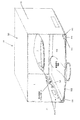
本発明の一実施形態は、負圧が形成され、被消毒物品周囲でそれを維持できる処理チャンバを備えた筐体を利用するものである。処理チャンバ内の過剰の周囲空気を除去して、負圧を形成することにより、物品を消毒するのに必要なプラズマの量が減じる。チャンバから過剰の周囲空気を除去するプロセスによってまた、処理チャンバ内の物品全体へのプラズマの分散も促進される。筐体は、上部51と、上部が取り付けられる基部52とを有する。基部はまた、プラズマ処理装置の部品のための保管領域としても機能し得る。例えば、ポンプ、バルブ、管類、排出チャンバおよびその他部品も基部に保管することができる。これは、本発明の必要条件ではなく、部品は、プラズマ処理装置の他の場所に保管しても、プラズマ処理装置とは別の場所に保管してもよい。
One embodiment of the present invention utilizes a housing with a processing chamber in which a negative pressure is formed and can be maintained around the article to be disinfected. By removing excess ambient air in the processing chamber and creating a negative pressure, the amount of plasma required to disinfect the article is reduced. The process of removing excess ambient air from the chamber also facilitates the dispersion of plasma throughout the article in the processing chamber. The housing has an
ある実施形態においては、少なくとも1つのコンフォーマブルウォールを有する処理チャンバを用いる。コンフォーマブルウォールは、物品に対して変形、崩壊、成形その他形成できる材料でできており、処理チャンバ内の空間や容積の量を減じる。被処理物品に実質的に適合する、または成形されて、物品周囲の対象としない空間の量を減じるコンフォーマブルウォールのこの能力によって、必要なプラズマの全体量をさらに減じることができる。コンフォーマブルウォールはまた、柔軟な物品も変形でき、物品中の空間や孔周囲へのプラズマの分散をさらに促すことができる。 In certain embodiments, a processing chamber with at least one conformable wall is used. The conformable wall is made of a material that can be deformed, collapsed, molded or otherwise formed on the article, reducing the amount of space and volume in the processing chamber. This ability of the conformable wall to reduce the amount of untargeted space around the article, which is substantially compatible with or molded into the article to be treated, can further reduce the total amount of plasma required. The conformable wall can also deform flexible articles, further facilitating the dispersion of plasma around spaces and holes in the articles.
その他の実施形態においては、物品を配置してシールできる柔軟な可撓性の袋の形態にある処理チャンバを用いる。この実施形態によれば、袋内部を負圧にすると、袋全体が、物品の形状に適合する。 In other embodiments, a processing chamber in the form of a flexible flexible bag into which articles can be placed and sealed is used. According to this embodiment, when the inside of the bag is made negative pressure, the entire bag conforms to the shape of the article.
さらに他の実施形態においては、少なくとも1つの排出チャンバを有することができる。周囲環境から空気をポンピングする、あるいは、排出チャンバにおいて隔離することによって、処理チャンバから過剰の空気を除去すると、処理チャンバが潰れて、処理チャンバ内の物品の形状に実質的に適合する。その結果、有効容積が減じ、処理サイクル中に減じるべき空気の容積も減じる。かかる実施形態において、処理サイクル中、有効容積の空気が、処理チャンバと第2の排出チャンバ間を往復する(プラズマ発生器を通して)。この容積の減少によって、空気をポンピングするのに費やす時間が少なくなり、物品を処理するのに用いるプラズマの濃度が増える。 In still other embodiments, it may have at least one discharge chamber. Removing excess air from the processing chamber by pumping air from the ambient environment or isolating it in the discharge chamber causes the processing chamber to collapse and substantially adapt to the shape of the article in the processing chamber. As a result, the effective volume is reduced and the volume of air to be reduced during the treatment cycle is also reduced. In such an embodiment, an effective volume of air reciprocates between the treatment chamber and the second discharge chamber (through a plasma generator) during the treatment cycle. This reduction in volume reduces the time spent pumping air and increases the concentration of plasma used to process the article.
さらに、一実施形態において、本発明は、少なくとも1つのフィルタリング機構を用いて、過剰のプラズマを除去し、使用者を健康被害から守ることを想定している。 Further, in one embodiment, the present invention envisions the use of at least one filtering mechanism to remove excess plasma and protect the user from health hazards.
本発明をより正確に理解するために、図面に示した具体的な実施形態により、本発明をより詳しく説明する。図面の縮尺は合っておらず、図面または詳細な説明における寸法については、開示した実施形態に特有のものである。本発明を意図する用途に供することを可能とするこれ以外の寸法も本発明の範囲に含まれるものとする。すなわち、図面は、本発明の典型的な実施形態を示すものに過ぎず、その範囲を限定するものではない。本発明を図面により、具体的かつ詳細に説明する。
本発明の実施形態は、物品の消毒装置および方法に関する。特に、本発明は、中に入れた物品を消毒できるプラズマ処理チャンバの実施形態を提供するものである。具体的な実施形態において、処理チャンバは、物品の形状に少なくとも適合可能であって、物品を消毒するのに必要なプラズマの量が減少する。 Embodiments of the present invention relate to disinfecting devices and methods for articles. In particular, the present invention provides an embodiment of a plasma processing chamber capable of disinfecting the articles contained therein. In a specific embodiment, the processing chamber is at least adaptable to the shape of the article, reducing the amount of plasma required to disinfect the article.
本発明は、標準的なエアレーションや消毒手順があまり効果のない、家庭または個人用物品、特に、多孔性物品や不規則な形状の物品について悪臭をきれいにする、特に、制御または排除するのに特に有用である。 The present invention is particularly effective in cleaning, particularly controlling or eliminating malodors in household or personal articles, in particular porous or irregularly shaped articles, for which standard aeration and disinfection procedures are less effective. It is useful.
本発明に関して用いられる「プラズマ」という用語は文言上簡便にするためであり、電流やコロナ放電により生成され、その物理的状態は問わない、高反応性イオン、原子および分子を指す。 The term "plasma" used in connection with the present invention is for the sake of wording simplicity and refers to highly reactive ions, atoms and molecules that are generated by electric current or corona discharge and whose physical state does not matter.
「空気」および「ガス」という用語は、装置操作中、移動する流体混合物を説明するのに本明細書では区別なく用いられる。 The terms "air" and "gas" are used interchangeably herein to describe a fluid mixture that moves during device operation.
数多くの変形例は、当業者には明白であるため、単なる例示を目的として、特に、以下の実施形態により、本発明を説明する。明細書および特許請求項で用いる単数形には、特に断りのない限り、複数形も含まれるものとする。 Since many modifications are obvious to those skilled in the art, the present invention will be described in particular for purposes of illustration only by the following embodiments. Unless otherwise specified, the singular form used in the specification and claims shall also include the plural form.
同じまたは同様の部品を示すのに同じ参照番号を用いた図面を参照する。本発明の実施形態を示す図面を参照すると、本発明のプラズマ処理装置10の実施形態は、処理チャンバの負圧の量によって決められる、サイズ可変の処理チャンバ100を含む筐体50を有する。処理チャンバ100を形成するバッグまたはコンフォーマブルウォール102の構成は変形する。さらに、少なくとも1つの排出チャンバ3がある。また、少なくとも1つの第1の排出チャンバ1および/または少なくとも1つの第2の排出チャンバ2がある。その他の実施形態では、処理のために物品の配置されるコンフォーマブルバッグを用いる。コンフォーマブルバッグは、必須ではないが、筐体50内に配置される。
Refer to drawings with the same reference numbers to indicate the same or similar parts. Referring to a drawing showing an embodiment of the present invention, an embodiment of the
一実施形態において、プラズマ発生器200は、物品を消毒および/または洗浄するために、処理チャンバにポンピングできるプラズマを形成するために用いられる。あるいは、エアロゾル化機構を、プラズマ発生器と共に、またはその代わりに用いて、物品を消毒および/または洗浄にすることができる。各一般部品には、1つ以上の従属部品が含まれる。これについては後述する。
In one embodiment, the
本発明の装置または部品を操作または指向するのに用いることのできる、業界で公知の様々な制御機構については、本明細書では、言及あるいは具体的には説明しない。本発明の電気配線については詳細に説明しない。ただし、当業者であれば、本明細書に記載した様々な部品の、例えば、部品同士、電源への取り付け方が分かり、本発明の利点の得られるやり方で、様々な種類のコントローラまたは操作機構で装置を構成することができる。最も簡便な文言だと、コントローラは、バルブ等の部品をプラズマ処理装置に移動または移すアクチュエータ機構とすることができ、これによって、処理手順を変更する、または処理手順を行う。コントローラは、コントローラの状態を検出して、コントローラを操作できる様々なセンサ800のいずれかに操作可能に接続することができる。本明細書に記載したのと実質的に同じ機能で、実質的に同じ所望の結果の得られる、様々なタイプのコントローラおよび本発明の部品の付属品も本発明の範囲に含まれる。
Various industry-known control mechanisms that can be used to operate or direct the devices or components of the present invention are not mentioned or specifically described herein. The electrical wiring of the present invention will not be described in detail. However, one of ordinary skill in the art will know how to attach the various parts described herein, eg, parts to each other, to a power source, and in a manner that benefits from the present invention, various types of controllers or operating mechanisms. The device can be configured with. In the simplest terms, the controller can be an actuator mechanism that moves or moves components such as valves to the plasma processing device, thereby changing or performing the processing procedure. The controller can detect the state of the controller and operably connect to any of the
一実施形態において、プラズマ処理装置10は、プラズマ発生器200、処理チャンバ100、およびプラズマ発生器と処理チャンバ間で空気を移動する機構を含む。プラズマ発生器は、コロナ、電解または紫外線によりプラズマを発生するものであるが、これらに限られない。ある実施形態には、本発明のプラズマ処理装置10と共に用いられるエアポンプ300の使用を促すフロースタイル発生器が含まれる。本発明の処理プロセスで用いられるプラズマ発生器により形成される様々な生成物はガス状またはプラズマ状である。変形例では、処理チャンバにおける物品を処理するのに、プラズマに加えて、またはプラズマの代わりに、エアロゾル殺菌剤を用いる。本明細書において、処理とは、微生物の死滅をはじめとする、生物または非生物の有機物質との反応のことを指す。処理には、有機物質と関連する悪臭の削減または排除も含まれる。
In one embodiment, the
一実施形態において、処理チャンバ100は、被処理物品の形状を少なくとも部分的に囲むまたは適合する形状に変化する少なくとも1つのコンフォーマブルウォール102を有する。コンフォーマブルウォールは、ガスケット103を用いて剛体板102にシールされる。その例を図16に示す。コンフォーマブルウォールに用いることのできる材料としては、これらに限られるものではないが、ポリエチレン、ポリプロピレン、EPDM、フッ素化炭化水素(PTFE等)、PEEKまたはこれらの組み合わせ、あるいは、適切な圧力差を保持するようにガスを通さないその他材料が挙げられ、本発明の消毒プロセスで生成され得るさまざまなプラズマおよび化学生成物に晒されても十分に耐性のあるものである。
In one embodiment, the
処理チャンバ100は、コンフォーマブルウォール102を使うと、中の被処理物品の形状に適合するよう調整できるため、処理サイクル中に移動させなければならない処理チャンバ中の空気の量も減じることができ、装置を加速させ、より効率的にすることができる。処理チャンバの適合性によってまた、十分な負圧が処理チャンバ内につくられると、プラズマ処理装置10は、中にある物品を圧搾または圧縮することもできる。この圧搾または圧縮によって、物品中の空隙からの汚染物質の除去や、プラズマの透過が向上する。本発明の実施形態が、エアロゾル殺菌剤を用いる場合には、負圧によってまた、物品の材料への殺菌剤の分配および透過も改善し得る。これによって、プラズマ発生装置10は、多孔性物品をより早く深くまで処理することができる。
The
一実施形態において、筐体の上部51を基部52の上で閉じ、操作可能に取り付けると、プラズマ処理装置10の筐体50が閉じて処理チャンバ100が形成される。剛体板101は、例えば、図2の工程1に示すように、被処理物品が中にある状態でコンフォーマブルシート102に対してシールされる。本実施形態によれば、例えば、ポンプ、バルブ、管類、配線および/またはその他部品等の装置10の操作機構の1つ以上が、基部52内に格納または保持される。あるいは、様々な部品を、筐体の他の部分または筐体から離して保持することができる。
In one embodiment, when the
他の実施形態において、処理チャンバは、例えば、図27、28および29に示すような少なくとも1つのコンフォーマブルウォール102を有するコンフォーマブルバッグ125で構成される。コンフォーマブルバッグは、負圧を形成し、プラズマや殺菌等の所望の処理材料を注入するのに必要なポンプ300およびその他部品に操作可能に接続することができる。一実施形態において、コンフォーマブルバッグは、例えば、図27、28および29に示すように、ポンプやその他部品が格納される基部に接続されている。コンフォーマブルバッグに負圧が形成されると、物品に向かって少なくともコンフォーマブルウォールが崩れて、物品の形状に少なくとも部分的に適合する。
In another embodiment, the processing chamber comprises, for example, a
コンフォーマブルバッグには、様々なシーリング装置130および業界で公知の技術を用いることができる。一実施形態において、バッグの、繰り返しの使用の際、バッグを開閉可能な再利用シールを用いることができる。例えば、家庭用保管袋に一般的に用いられているようなスライドシールやジッパーシールを用いたり、別の部品をバッグに取り付けてシールしてもよい。バッグはまた、折り畳んでつまんだり、気密シールできるようなその他のやり方でシールすることができる。
一実施形態において、中に入れた物品が周囲環境から完全に隔離されるよう、バッグを永久シールすることができる。この実施形態によれば、コンフォーマブルバッグ125は使い捨てとなり、物品を清浄かつ/または消毒した後は、ポンプ300およびプラズマ処理装置の他の部品からバッグを取り出すことができる。新たな交換バッグをプラズマ処理装置に取り付けて、他の物品の処理をすることができる。
In one embodiment, the bag can be permanently sealed so that the articles contained therein are completely isolated from the surrounding environment. According to this embodiment, the
あるいは、中の物品を受け取って隔離するためにバッグを繰り返し開閉可能とするシール130を付けることで、バッグを再利用可能とすることができる。この実施形態によれば、コンフォーマブルバッグは、ポンプおよびその他の部品に永久取付することができる。あるいは、バッグをプラズマ処理装置から取り出して、交換することができる。コンフォーマブルウォールまたはコンフォーマブルバッグのコンフォーマル材料を保護するために、実施形態には、コンフォーマル材料と被処理物品間の処理チャンバ内部に亀裂防止ライニングを含めることができる。当業者であれば、本発明の処理チャンバおよびシールの実施形態に用いることのできる様々な材料およびシールを判断することができる。
Alternatively, the bag can be made reusable by attaching a
処理チャンバとプラズマ発生器間の周囲空気の移動には、真空ポンプ300と、処理チャンバ100、プラズマ発生器200および真空ポンプを接続する気密管とが使われる。本発明で用いるのに好適なポンプとしては、振動ピストン、ピストン式、ダイアフラム、振動プランジャ、振動ダイアフラム、蠕動、容積式、遠心、スクリュー、ブロワおよび回転羽根式ポンプが挙げられるが、これらに限られるものではない。
A
プラズマ処理装置の一実施形態は、装置の様々な部品間でエアフローを指向するバルブ機構500を含む。本発明に好適なバルブの種類としては、逆流と選択バルブの両方が挙げられる。用いることのできる逆流バルブとしては、4/2、4/3、5/2、または5/3バルブが挙げられるが、これらに限られるものではない。マルチソレノイドバルブを配置して、システムにおけるエアフロー方向を逆にすることもできる。ポンピング機構を用いる場合は、逆流させるエアフロー逆流バルブは取り除くことができる。選択バルブは、複数の出口ポートを選択する共通の入口ポートとなるバルブとすることができる。当然、部品間のエアフローは、1つまたはいくつかの部品に直接接続された管またはマニホルドを通って移動する。
One embodiment of the plasma processing apparatus includes a
周囲環境15を往復するポンピングは可能であるが(図3A−8Dに示すとおり)、本発明のある実施形態は、処理チャンバ100に接続された1つ以上の排出チャンバ3(エアフローに関して)を含む。これら排出チャンバによって、プラズマと、軽減されるまで悪臭を含ませておくことができ、かつ、物品をより効率的に処理することができる。一実施形態において、排出チャンバ3は、空気が取り込まれても形状が変化しないよう、または変化が最少となるよう、剛性材料で形成されている。変形例において、排出チャンバは、空気がポンピングされて排出チャンバを出入りする際、膨張と収縮が可能な可撓性またはコンフォーマブル材料で形成される。本明細書で、第1および第2の排出チャンバを参照する際、特に断りのない限り、特定の目的について排出チャンバの存在を識別するためだけであり、少なくとも1つあればよい。このように、「第1」は、2つ以上なければならないということを示唆するものではない。さらに、第2の排出チャンバを参照する場合、第1の排出チャンバがなければならないことを示唆するものではない。これらの参照は、特定の要素について、時系列、構造の向きまたは方向(例えば、左または右、上または下)を与えようとするものではない。
Although pumping back and forth in the
一実施形態は、2つの排出チャンバ3、第1の排出チャンバ1および第2の排出チャンバ2を含む。各排出チャンバは、例えば、図2および図9A−11Dに示すとおり、処理チャンバ100に(エアフローに関して)接続することができる。本実施形態において、処理チャンバ100からの周囲空気は、特定のプロセス条件に合うまで、第1の排出チャンバ1にポンピングすることができる。かかるプロセス条件とは、例えば、エアポンピングの際の所定のタイムリミット、または圧力センサ850等のセンサ800が、処理チャンバ100で所定の圧力に達したことを示すときの所定のタイムリミットである。第1のプロセス条件が満たされた後、処理チャンバに残った空気は、第2の排出チャンバ2にポンピングすることができる。
One embodiment includes two
一実施形態において、コントローラは、1つ以上のセンサ800により測定される処理チャンバ内で得られる明確な「絶対」圧力(大気に対して測定)に基づいて、装置を第1段階から他の段階へ切り替える(例えば、第1から第2真空サイクルへ)ことができる。本実施形態において、圧力は、第1の真空サイクル中処理チャンバ内で測定される。処理チャンバ壁は物品に実質的に適合したときを判断するために、処理チャンバ内の圧力が所定の圧力に達するまで、第1の真空サイクルを継続することができる。この所定の圧力レベルは、処理チャンバのコンフォーマブルウォールの剛性にある程度依存している。例えば、厚く、より剛性のコンフォーマブルウォール材料だと、材料を物品に適合させるのに、より低い圧力が必要とされる。当業者であれば、特定の材料でできたチャンバを適合させるのに適切な圧力を判断することができ、これは、チャンバに真空を適用して、コンフォーマブルウォールが潰れて、チャンバ内の物品に適合する際の圧力を測定することでわかる。第1の真空サイクルの終了(処理チャンバのコンフォーマル材料が、物品を実質的に圧搾またはその他変形することなく、チャンバ内で物品に実質的に適合した点)を判断するには、圧力センサが、処理チャンバ内の圧力が、コンフォーマブルウォール材料を変形させるのに必要な圧力より若干低い圧力を判断する。一実施形態において、コンフォーマブルウォール102が、物品75に実質的に適合したことを示すのに十分な負圧レベルは、約0.00PSIV〜約−14.7PSIVである。より具体的な実施形態において、コンフォーマブルウォールが、物品に実質的に適合したことを示すのに十分な負圧レベルは、約−0.001PSIV〜約−5PSIVである。
In one embodiment, the controller implements the device from the first stage to the other stage based on the clear "absolute" pressure (measured against the atmosphere) obtained in the processing chamber measured by one or
具体的な実施形態において、センサ800が、例えば、圧力測定によって、処理チャンバが物品75に実質的に適合していると判断すると、第2の真空サイクルが始まる。第2の真空サイクルで、処理チャンバ100内の真空が増すことにより、物品を圧搾することができ、これによって、物品に対してコンフォーマブルウォールが押し付けられる。本実施形態において、第2の真空サイクルは、次の3つのうち少なくとも1つが生じるまで継続される。すなわち、1)チャンバ内の圧力が所定値に達する、2)圧力が、真空ポンプにより得られる最大真空に達する、または3)ΔP/Δt(後述)が安定、もしくは安定し始める。
In a specific embodiment, the second vacuum cycle begins when the
一実施形態において、コントローラに操作可能に接続されたセンサ800は、処理チャンバで測定された圧力の変化率ΔP/Δtに基づいて、第1または第2の真空サイクルの終了を判断する。この方法は、処理チャンバ内のコンフォーマル材料の変化にはあまり影響を受けず、被処理物品の物理的な変形特性により多くの影響を受ける。例えば、剛性物品75(例えば、ラクロスのヘルメット)を処理するときは、第1の真空サイクルの終了時のΔP/Δtは、同様のサイズの柔らかく曲げやすい物品(例えば、装飾用クッション)を処理する時よりかなり大きくなる。一実施形態において、プラズマ処理装置10は、処理シーケンスを開始させるのに用いる異なるΔP/Δt値パラメータを構成する処理物品の種類に基づいて、異なる設定オプションを有する。例えば、柔らかい物品についての設定では、硬い物品の設定よりも小さいΔP/Δt値を用いる。第1の真空サイクル中、処理チャンバから過剰に空気が除去されると、処理チャンバ内の圧力が、チャンバが物品に適合するまで、かなり一定の速度で減じる。コンフォーマブルウォール102が、容易に潰れる(物品と接触することによる)のを防ぐと、ΔP/Δtは即時に増大する。このように、圧力を測定し、ΔP/Δtを計算すると、処理チャンバ壁が物品に実質的に適合する時をコントローラは予測でき、その時点で装置は第2の真空サイクルを開始することができる。
In one embodiment, the
さらなる実施形態において、ΔP/Δt値を用いて、第2の真空サイクルの終了を判断することができる。1つ以上のポンプが、最大真空量に達し始めると、ΔP/Δt値は、安定化し始め、コントローラは、装置を次の段階へ切り替える。この場合も、処理チャンバのコンフォーマブルウォールが、物品に実質的に適合するものの、物品を実質的には変形していない時に観察しながら、ΔP/Δtを測定することにより、第1の真空サイクルの終了を示す適切なΔP/Δt値を経験的に判断することができる。第2の真空サイクルの終了を示すのに用いられるΔP/Δt値は、ポンプが最大真空に達する、または物品の変形が止まる際のΔP/Δt値の安定化により判断することができる。 In a further embodiment, the ΔP / Δt value can be used to determine the end of the second vacuum cycle. When one or more pumps begin to reach maximum vacuum, the ΔP / Δt values begin to stabilize and the controller switches the device to the next stage. Again, the first vacuum by measuring ΔP / Δt while observing when the conformable wall of the processing chamber is substantially compatible with the article but is not substantially deformed. Appropriate ΔP / Δt values indicating the end of the cycle can be empirically determined. The ΔP / Δt value used to indicate the end of the second vacuum cycle can be determined by stabilizing the ΔP / Δt value when the pump reaches maximum vacuum or the deformation of the article ceases.
プラズマ処理装置10のある実施形態において、ポンプにおける負荷変化率(時間(t)変化に対する電流(I)変化:ΔI/Δt)を測定する。基本的に、ΔP/Δt値と同様に、同じ事象(例えば、物品に適合し、最大真空に達すること)が高いΔI/Δt値をもたらし、その測定結果は同様に用いられる。
In one embodiment of the
処理チャンバにおいて所定の圧力レベルに達したら、様々なコントローラのいずれかを用いて、バルブ機構500を操作して、第1の排出チャンバ1からの周囲空気の除去を中断し、処理チャンバから残りの空気を除去するのを開始して、空気を、第1の排出チャンバ1でなく第2の排出チャンバ2へ入れ、バルブ機構500に操作可能に接続されたポンプ300が、処理チャンバに真空を引いてより負圧にし、処理チャンバ100のコンフォーマブルウォール102が潰れ、さらに、物品をできる限り圧搾または圧縮するようにする。図11A−11D、図12、および図13は、第1の排出チャンバ1および第2の排出チャンバ2を有するプラズマ処理装置10を示すが、これらに限られるものではない。図13において、第1の排出チャンバは、筐体50により形成され、第2の排出チャンバは中にある。
Once a predetermined pressure level has been reached in the processing chamber, one of the various controllers is used to operate the
装置の一実施形態は、処理時間を減じるための真空リザーバシステム900を含む。真空リザーバシステムは、十分な負圧に耐え得る真空リザーバ920と、真空リザーバに操作可能に接続された負圧に耐え得るハイフローバルブ940と、同じく真空リザーバに操作可能に接続された真空ポンプとを有する。一実施形態において、真空リザーバシステムは、処理チャンバに操作可能に接続されていて、ハイフローバルブが開くと、周囲空気が処理チャンバから真空リザーバに入るようになっている。
One embodiment of the device includes a
さらなる実施形態において、装置に電源を入れると、ハイフローバルブが閉じ、真空ポンプが真空リザーバに負圧を引いて、負圧チャンバを形成することができる。 In a further embodiment, when the device is powered on, the high flow valve closes and the vacuum pump can draw negative pressure into the vacuum reservoir to form a negative pressure chamber.
被処理物品は、まず、処理チャンバ内に配置され、シールされて、ハイフローバルブを開くと、2つのチャンバ間の圧力差が平衡に達すると、空気が、処理チャンバから真空リザーバへすぐに流れる。処理チャンバと真空リザーバ間が圧力平衡に達したら、ハイフローバルブを閉じ、真空ポンプを作動させて、真空リザーバに再び負圧を引く。第1の真空サイクルの終了を示す、上述した圧力パラメータに達するために、より多くの空気を除去しなければならない場合は、かかるパラメータに達するまで第1の真空サイクルを続ける。 The article to be processed is first placed in the processing chamber, sealed, and the high flow valve is opened, and when the pressure difference between the two chambers reaches equilibrium, air immediately flows from the processing chamber to the vacuum reservoir. When the pressure equilibrium is reached between the processing chamber and the vacuum reservoir, the high flow valve is closed and the vacuum pump is activated to apply negative pressure to the vacuum reservoir again. If more air must be removed to reach the pressure parameters described above, which indicates the end of the first vacuum cycle, the first vacuum cycle is continued until such parameters are reached.
負圧の真空リザーバシステムを利用するこの技術によって、ハイフローポンプを必要とすることなく、あるチャンバから空気を非常に急速に除去することができる。代わりに、ポンプを用いて、処理プロセスの遊び工程中に負の真空「リザーバ」を徐々に構築してもよく、ハイフローバルブを用いて、必要になるまで、負圧を保持してもよい。 This technique, which utilizes a negative pressure vacuum reservoir system, allows air to be removed from a chamber very quickly without the need for a high flow pump. Alternatively, a pump may be used to gradually build a negative vacuum "reservoir" during the play process of the processing process, or a high flow valve may be used to hold the negative pressure until needed.
一実施形態において、真空リザーバは、装置の他の部品と同じ区画に配置された剛性容器である。一実施形態において、真空リザーバは、剛性円筒チャンバである。他の実施形態において、保管区画の他の部品の周りの空隙を充填し、他の部品を適所に保持するのをさらに補助する剛性容器である。 In one embodiment, the vacuum reservoir is a rigid container located in the same compartment as the other parts of the device. In one embodiment, the vacuum reservoir is a rigid cylindrical chamber. In another embodiment, it is a rigid container that fills the voids around other parts of the storage compartment and further assists in holding the other parts in place.
さらなる実施形態において、第2の排出チャンバと処理チャンバ間でポンピングされて、第2の排出チャンバを出入りする容積の周囲空気が、プラズマ発生器200を通過する。この配置には次のような利点がある。すなわち、1)安全である−プラズマに変換されるガスの容量が限られると、装置から、有害となる可能性のある量のプラズマが生成されるのを防ぐ助けとなる。2)効率的である-処理チャンバと第2の排出チャンバ間でポンピングされる空気の容積が小さいと、サイクルタイムが短くなり、物品を処理するのに用いるプラズマの濃度が高くなる(容量が小さくて、チャンバ間を動く際に、発生器を複数回通るときはとりわけである)。本発明にはさらに、フィルタリング機構を用いて、周囲環境15を、第1の排出チャンバ1、第2の処理チャンバ100、またはその両方の代わりに用いることも含まれる。
In a further embodiment, a volume of ambient air pumped between the second discharge chamber and the processing chamber that enters and exits the second discharge chamber passes through the
プラズマを処理チャンバへポンピングすると、ファイバー、開口、ポア、空間および物品75の接触表面を囲み、浸透する。プラズマイオンの反応性によって、処理チャンバおよび/または物品の生物、その他有機材料と効率的かつ即時に反応し始める。この接触を促すために、処理中に休止期間250を設けることができ、処理サイクル中に形成されたプラズマが、所定の時間にわたって処理チャンバに残る。図2に、処理サイクルに組み込むことのできる休止期間の例を示す。休止期間の長さは、例えば、用いているプラズマの種類、物品のサイズまたは構成、物品についている有機または生物材料の量、その他因子をはじめとするいくつかの要因に依存し得る。
Pumping the plasma into the processing chamber surrounds and penetrates the contact surfaces of fibers, openings, pores, spaces and
一実施形態において、第1の排出チャンバ1は、処理チャンバ100を形成するコンフォーマブルシート102の外側表面に対してシールされた剛性エンクロージャである。この実施形態によれば、第1の排出チャンバは、基部52にある筐体取付具の上部51により形成され、第2の排出チャンバ2と処理チャンバ100の両方を含むことができる(装置が閉じている時)。この例を図15に示す。他の実施形態において、第1の排出チャンバ1は、少なくとも1つのコンフォーマブルサイド、またはコンフォーマブルバッグを有している。同様に、ある実施形態において、第2の排出チャンバは剛性で、少なくとも1つのコンフォーマブルサイドを有していてもよい。
In one embodiment, the
本発明のある実施形態は、空気を移動させる2つ以上の装置を含む。例えば、ある実施形態は、過剰の空気を処理チャンバから第1の排出チャンバまたは周囲環境15へ即時に除去するための第1のポンプ300と、処理チャンバから第2の排出チャンバへ空気を移動して、物品を圧搾するために、十分な能力で、処理チャンバ内に負圧を作り、または負圧を増大する第2のポンプ300とを含む。
One embodiment of the present invention includes two or more devices that move air. For example, in one embodiment, excess air is transferred from a processing chamber to a first discharge chamber or a second discharge chamber with a
多数の真空ポンプを直列または並列で用いることも可能であり、2つ以上のポンプを並列と直列の構成で切り替える少なくとも1つの実施形態が含まれる。並列構成だと、ある時間内に大容量の空気を移動させることができ、直列構成だと、処理チャンバで引くことのできる負圧が増大する。図4A−4Eに、これらのポンプ構成の例を示すが、これらに限られるものではない。 It is also possible to use a large number of vacuum pumps in series or in parallel, including at least one embodiment in which two or more pumps are switched in parallel and in series configurations. With the parallel configuration, a large volume of air can be moved within a certain period of time, and with the series configuration, the negative pressure that can be drawn by the processing chamber increases. 4A-4E shows examples of these pump configurations, but the present invention is not limited thereto.
例えば、コントローラが、第1の排出チャンバ1へ指向する空気を、第2の排出チャンバ2へ指向するように、バルブを再構成する時を示す圧力差であって様々な空気の通り道やチャンバ間の圧力差をモニターするために、本発明のある実施形態はまた、1つ以上のセンサ800を含む。一実施形態において、センサ800は、処理チャンバ100内の圧力を検出し、および/または反応させ、並びに様々な公知の制御機構のいずれかを動作させることで、特定のイベントを開始可能な圧力センサ850である。他の実施形態において、システムのいずれかの圧力に応答する圧力センサ850を用いて、同じまたはその他のイベントを動作させることができる。図13、14および17−23に、圧力センサ850を用いる実施形態を示す。圧力センサおよびその他の種類のセンサは、数多くの目的および装置について業界において公知である。当業者であれば、本明細書に記載したチャンバのいずれかで用いることのできる、または圧力が測定されるチャンバに接続されたガスラインに接続可能なものとして、圧力センサかその他の適切なセンサを決定することができる。同じく、ある実施形態においては、圧力センサ850でなく、1つ以上のガスフローメータを用いることも可能である。
For example, a pressure difference indicating the time when the controller reconfigures the valve so that the air directed to the
本発明の他の実施形態は、物品75そのものから生じる悪臭を除去し、過剰のプラズマと反応し得るフィルタリング機構400を含む。図13および14は、フィルタ400を含む実施形態を示すが、これに限られるものではない。一実施形態において、フィルタリング機構は、処理チャンバ100と、実施形態に応じて、第1の排出チャンバ1、第2の排出チャンバあるいは周囲環境15とのいずれかの間に配置される(エアフローに対して)。プラズマの中には、人体に有害と考えられるものもあるため、フィルタリング機構が、本発明の実施形態における別の安全対策となり得る。フィルタリング機構400は、電気的に生成されたプラズマを触媒して、より安定な生成物を形成する触媒(二酸化マンガン等)を含んでいてもよい。あるいは、フィルタリング機構400は、電気的に生成されたプラズマと反応して、より安定な生成物を形成する反応物質材料(炭素または酸化性金属、例えば、鉄等)でできた消耗フィルタであってもよい。フィルタリング機構400 はまた、触媒と消耗フィルタの組み合わせとすることもできる。消耗フィルタを用いるフィルタリング機構400の一実施形態は、交換式カートリッジとすることができる。
Another embodiment of the present invention includes a
図17−23に例を示す一実施形態は、第1の真空サイクル中に処理チャンバ100から出てくる空気から悪臭を除去するための、少なくとも1つの悪臭フィルタリング機構401と、処理サイクル完了後、周囲空気から過剰のプラズマを除去するフィルタリング機構402とを利用するものである。さらなる安全性のために、ある実施形態には、処理サイクル後、処理チャンバを解除する前に、処理チャンバからのプラズマ除去レベルを判断する検出機構が含まれる。
One embodiment, illustrated in FIG. 17-23, comprises at least one
更なる実施形態には、処理チャンバに操作可能に接続された(エアフローに対して)芳香カートリッジ700が含まれ、一例を図16および図17−23に示す。本実施形態において、予定数の処理サイクル完了後、空気を能動的(例えば、ポンピングまたは強制的に通過)あるいは受動的(例えば、処理チャンバにおいて負圧を保持しているバルブを解放して、周囲の周囲空気を取り込むことにより)に、芳香カートリッジ700に通過させて、処理中の物品に香気を付与することができる。かかる実施形態において、芳香カートリッジ700は、プラズマ発生器と直列か並列のいずれかで(空気経路に対して)配置されてよい。別の実施形態において、芳香カートリッジ700は、エアポンプ300と直列か並列のいずれかで(空気経路に対して)配置されてよい。芳香カートリッジ700はまた、バルブに対して直列に配置され、処理チャンバ100に操作可能に取り付けてもよい。かかる実施形態において、バルブは、芳香カートリッジ700の処理チャンバ100側に配置する、または処理チャンバ100の逆の芳香カートリッジ700の側に配置してよい。ある実施形態において、本発明はさらに、フィルタリング機構と共に芳香カートリッジを用いる。具体的な実施形態において、芳香カートリッジをフィルタリング機構と組み合わせる。
A further embodiment includes an
その他の装置および技術と、本発明の実施形態を組み合わせて、物品についている生きている微生物を効率的に減じることができる。一実施形態に、UV光を処理チャンバ内の物品に放出するべく配置されたUV光源150が含まれる。UV照射装置は、病室やその他の環境において、微生物を死滅させるのに用いられてきた。UV光源を利用する本発明の実施形態によれば、抗菌効果が増大する。図2および16に、本発明の実施形態に組み込むことのできるUV光源の例を示すが、これらに限られるものではない。
Other devices and techniques can be combined with embodiments of the present invention to efficiently reduce living microorganisms attached to an article. One embodiment includes a
物品によっては、微生物を死滅させ、悪臭を除去するという所望の効果を得るために、プラズマや殺菌剤といった処理材料を含む空気をさらに必要とし、より直接的に適用することを必要とする領域、スペースまたは構造を持つ。本発明の実施形態の更なる特徴としては、こうした物品を最大限処理できるよう処理空気を指向することができる。本発明の一実施形態は、処理チャンバにつながる複数のポート750を有する。一例を図24および25B示す。図27、28および29にコンフォーマブルバッグを示す。これらのポートは、特定のパターンで配置されて、処理チャンバに出入りする処理空気の流れを調整するばかりでなく、ポートに取り付けられて特定の物品の処理を向上させるホース、漏斗または拡散器といった、ガス指向部品755を別途、配置させることもできる。例えば、ボクシングのグローブの内側を処理するには、グローブの内側へ及び内側から処理ガスを直接通すのが望ましい。
Areas that require more air, including treatment materials such as plasma and disinfectants, and more direct application, in order to obtain the desired effect of killing microorganisms and removing malodors, depending on the article. Has space or structure. A further feature of the embodiments of the present invention is that the treated air can be directed to maximize the treatment of such articles. One embodiment of the invention has a plurality of
一実施形態に、少なくとも1つのポートに取り付けられた可撓性管の形態のガス指向物品が含まれ、図24に示す例によれば、物品、例えばグローブ、の内側に管の端部を挿入可能で、処理サイクル中、物品の内側へ及び内側からガスを指向することができる。あるいは、例えば、タオルを処理する時は、全体的にガスを拡散させて処理チャンバを出入りさせるのが望ましい。他の実施形態によれば、処理チャンバの壁、例えば、剛体板101等、に複数のポート75を用いることができる。さらに他の実施形態によれば、例えば、図25Aおよび25Bに示すように、拡散アタッチメントを1つ以上のポートに取り付けることができる。
One embodiment includes a gas-oriented article in the form of a flexible tube attached to at least one port, with the end of the tube inserted inside the article, eg, a glove, according to the example shown in FIG. It is possible to direct the gas in and out of the article during the processing cycle. Alternatively, for example, when processing a towel, it is desirable to diffuse the gas as a whole to move it in and out of the processing chamber. According to other embodiments, a plurality of
本発明のプラズマ処理装置10は、特定のサイズの物品75に限定されない。処理できる物品のサイズは、処理チャンバ100の寸法および/または容積によってのみ限定される。一実施形態において、プラズマ処理装置は、持ち運び可能で、家庭用途に好適である。例えば、家庭用物品や衣類を処理するのに有用な本発明のプラズマ処理装置は、携帯用の筐体50にフィットするサイズの処理チャンバを有することができる。他の実施形態によれば、携帯用処理装置は、永久配置する、または、少なくとも持ち運び可能とせず、大きな物品を入れられるサイズの処理チャンバ、または工業または商用とすることができる。一実施形態によれば、処理チャンバの容積は約50ml〜約500リットルである。より具体的な実施形態によれば、処理チャンバの容積は約200ml〜50リットルである。
The
本発明の装置を用いると、真空段と再充填段階を含む繰り返し可能なプロセスを用いることにより物品を処理することができる。このプロセスの一実施形態を、図17−23に示す。例えば、図18に示す、このプロセスの真空段において、コンフォーマブルウォール102を有する処理チャンバ100に負圧を引くと、コンフォーマブルウォールが、物品の上で潰れて、処理チャンバからできる限り多くの周囲空気を除去するために、処理中の物品をさらに圧搾または圧縮することができる。図19に示す、本プロセスの再充填段階において、中立圧力または正圧になるまで、処理チャンバ内で負圧を反転または解除する。1つの真空段と1つの再充填段階で1つの処理サイクルが構成される。ある実施形態によれば、真空段階と再充填段階を複数回繰り返すと、多数の多処理サイクルを行うことができる。
Using the apparatus of the present invention, articles can be processed using a repeatable process that includes a vacuum stage and a refilling stage. An embodiment of this process is shown in Figure 17-23. For example, in the vacuum stage of this process shown in FIG. 18, when negative pressure is applied to the
さらなる実施形態によれば、多数の処理サイクル後には最終サイクルがあり、最終サイクルでは、図23に示すように、処理チャンバから物品を取り出すことのできる中立または略中立圧力に、処理チャンバ内の圧力が戻るまで、空気を処理チャンバに通過させる。ある実施形態によれば、最終サイクル中、図22および23に示すように、処理チャンバに入る前に、空気は芳香カートリッジを通過し、処理中の物品に芳香を付与する。 According to a further embodiment, there is a final cycle after a number of processing cycles, in which the pressure in the processing chamber is at a neutral or substantially neutral pressure at which the article can be removed from the processing chamber, as shown in FIG. Allow air to pass through the processing chamber until it returns. According to one embodiment, during the final cycle, as shown in FIGS. 22 and 23, air passes through the aroma cartridge and imparts aroma to the article being processed before entering the processing chamber.
本方法の具体的な実施形態によれば、プラズマを利用して、処理チャンバ内の物品を処理する。かかる実施形態において、再充填段階において処理チャンバに入る空気は、処理チャンバ100に入る前に、プラズマ発生器200を通過する。プラズマの反応性は高いため、物品の有機物質を攻撃し得る。物品の有機物質が分解または不活性化されて、悪臭中和、脱臭または抗菌効果をもたらす。
According to a specific embodiment of the method, plasma is used to process the article in the processing chamber. In such an embodiment, the air entering the processing chamber during the refilling step passes through the
変形例によれば、プラズマに加えて、またはプラズマの代わりに、エアロゾル殺菌剤を用いて物品を処理することができる。かかるエアロゾル殺菌剤としては、過酸化水素やアルコールが例示されるが、これらに限られるものではない。装置の一実施形態においては、エアロゾル化機構960を組み込んで、周囲空気が処理チャンバ100に戻ったときに、エアロゾル殺菌剤を物品75に適用している。図22Bに、本実施形態の例を示すが、これに限られるものではない。本実施形態においては、殺菌剤は、各処理サイクル中、または最終再充填サイクル中に用いられる。ある実施形態によれば、エアロゾル化機構には、流体リザーバ965があって、殺菌剤と、流体殺菌剤をエアロゾル化するためのノズル970とを有しており、流体殺菌剤が周囲空気通路を通過するようになっている。本発明の実施形態で用いることのできるエアロゾル化ノズルとしては、ベンチュリスタイル、ジェットオリフィスノズル、またはリザーバから流体の十分に小さい液滴を形成して、周囲空気の流れにより処理チャンバへ運ぶことのできる業界で公知のその他ノズルが例示されるが、これらに限られるものではない。さらなる実施形態によれば、エアロゾル機構は、処理チャンバへつながる周囲空気通路に接続されているのが好ましく、周囲空気が処理チャンバを通過している間エアロゾル化機構を作動させることができ、エアロゾル殺菌剤が、再充填のときに処理チャンバへ注入される。変形例によれば、エアロゾル化機構を用いて、殺菌流体の代わり、または殺菌流体に加えて、芳香の付いた流体を分散させる。
According to variants, the article can be treated with an aerosol disinfectant in addition to or in place of the plasma. Examples of such aerosol disinfectants include, but are not limited to, hydrogen peroxide and alcohol. In one embodiment of the device, an
本プロセスの真空段には、第1および第2の真空サイクルが含まれる。第2の真空サイクルを含む実施形態において、第1の真空サイクルは、まず、処理チャンバ100から周囲空気を除去する。これによって、処理チャンバのコンフォーマブルウォール102が、物品に適合し始め、処理チャンバ内の空気の有効容積が減じる。第1の真空サイクル中、周囲空気の除去を、処理チャンバ内を負圧にするのに行う必要はないが、行うこともできる。本プロセスのこの工程に続いて、第2の真空サイクルを行って、処理チャンバに少なくとも最小の負圧を引いて、減じた有効容積の残りの周囲空気の全てまたは大半を移動する。第2の真空サイクルにより、直接、あるいは、プラズマ発生器により、残りの周囲空気を排出チャンバへと除去することができる。その後、再充填段階において、排出チャンバからの空気は、プラズマ発生器を通って、処理チャンバに戻る。後の処理サイクルによって、排出チャンバと処理チャンバとの間で減じた容積の空気が往復する(プラズマ発生器を通して)。有効容積を減じると、往復する空気をポンピングするのに必要な時間が短くなって、処理の効率が上がる(上述した通り)。
The vacuum stages of this process include first and second vacuum cycles. In embodiments that include a second vacuum cycle, the first vacuum cycle first removes ambient air from the
上述の通り、プラズマ処理装置のある実施形態では、少なくとも1つのコンフォーマブルウォール102を有するシール可能な130コンフォーマブルバッグ125を処理チャンバ110として利用する。コンフォーマブルバッグは、剛体板101にシールされるコンフォーマブルウォール102を用いて、実施形態で記載した方法および部品のいずれも利用することができる。コンフォーマブルバッグを処理チャンバとして用いる実施形態において、シールされた入口および出口ポートを形成して、サイクル中、空気を出し入れすることができる。ポートはまた、ガス指向部品のためのアタッチメントを有していてもよい。かかる実施形態において、処理チャンバは筐体50に囲まれていてもよいし、変形例においては、処理チャンバは筐体に囲まれていなくてもよい。処理チャンバが囲まれていない方が有利な場合の例を挙げると、装置を用いて非常に大きな物品(例えば、マットレス)を処理する場合である。かかる実施形態においては、被処理物品はコンフォーマブルバッグに入れ、バッグの開口部をシールして閉じる。
As mentioned above, in some embodiments of the plasma processing apparatus, a sealable 130
本発明のプラズマ処理装置10を用いて物品を処理する方法は、物品を処理チャンバ100に入れ、処理チャンバ100を閉じたときに開始される。第1の真空サイクルが始まる。一実施形態において、第1の真空サイクル中、処理チャンバ100から空気を除去し、直接、または、フィルタリング機構400から周囲環境15へ送る。1つ以上のプロセス条件が満たされたら(例えば、タイムリミットに達したら、または圧力センサ850が、処理チャンバ100内が所定の圧力に達したことを示したら)、コントローラが作動するまで、第1の真空サイクルを続ける。その後、コントローラが、プラズマ発生器200を動作させて、再充填サイクルが開始される。周囲環境15から、動作したプラズマ発生電極200へ空気が移動し(能動的に、エアポンプ300を用いて空気を送る、または受動的に、バルブを単に開いて、相対圧力を平衡にする)、プラズマが発生する。上述した通り、センサ850が1つ以上のプロセス条件を満たすと判断するか、またはコントローラ850を動作させるまで、プラズマを処理チャンバ100へ通す空気の能動的または受動的な移動を続ける。一実施形態において、コントローラは、所定の時間にわたって処理を中断し、その間プラズマは処理チャンバ内で物品を消毒する。処理中断後、コントローラを動作させて、第1の真空サイクルを再び開始し、センサが1つ以上のプロセス条件を満たすと判断するまで、空気を処理チャンバ100から、フィルタリング機構を通して、周囲環境15へ再度ポンピングする。
The method of processing an article using the
さらなる実施形態において、コントローラは、さらなる処理サイクル(予定されたレジームに応じて)を開始する。コントローラは、プラズマ発生器200を作動させ、空気の流れを切り替えて、周囲環境15から、プラズマ発生器200へ流し、プラズマが処理チャンバ100に入る。最後の処理サイクル後、コントローラは、最終真空サイクルを開始し、処理チャンバ100からの空気を、直接、またはフィルタリング機構400を通して、ポンピングして周囲環境15へ戻す。予定数の処理サイクルと最終真空サイクルの完了後、コントローラは、最終フローサイクルを開始し、センサが、特定のプロセス条件を満たすと判断するまで(例えば、タイムリミット、または圧力センサ850が、処理チャンバ100で所定の圧力に達したことを示すとき)、周囲環境15からの空気を、処理チャンバ100へ入れる(能動的または受動的に)。ある実施形態によれば、最終フローサイクルによって、空気が周囲環境15から直接処理チャンバ100へ入れられる。他の実施形態によれば、芳香カートリッジ700を通して、物品に芳香が付与される。センサが、全処理レジームが完了したと判断したら、物品を処理チャンバ100から取り出してよい。
In a further embodiment, the controller initiates a further processing cycle (depending on the planned regime). The controller operates the
一実施形態において、第1の真空サイクル中、空気を処理チャンバ100から除去し、フィルタリング機構400を通して、または作動させたプラズマ発生器200を通して、第1の排出チャンバ1へ直接入れる。かかる実施形態において、コントローラに操作可能に接続されたセンサ800が、第1の真空サイクルの終了を示す、特定のプロセス条件を満たす(例えば、タイムリミット、または圧力センサ850が、処理チャンバ100で所定の圧力に達したことを示すとき)と判断するまで、第1の真空サイクルを続ける。
In one embodiment, during the first vacuum cycle, air is removed from the
第1の真空サイクルの開始時にプラズマ発生器が作動していない実施形態において、第1の真空サイクルが終了したら、コントローラはプラズマ発生器200を動作させ、センサが、特定のプロセス条件を満たす(例えば、タイムリミット、または圧力センサ850が、処理チャンバ100で所定の圧力に達したことを示すとき)と判断し、コントローラを作動させるまで、空気を第1の排出チャンバ1から動作させたプラズマ発生電極を通して送り(能動的または受動的に)、それによりプラズマが発生し、処理チャンバ100へ入る。
In an embodiment in which the plasma generator is not activated at the start of the first vacuum cycle, at the end of the first vacuum cycle, the controller operates the
プラズマ発生器200が、第1の真空サイクルの開始時に作動している場合は、発生器200は、第1の真空サイクルが終了した後も作動したままとし、空気は、第1の排出チャンバ1から、発生器200を通って、処理チャンバ100に入る。そして、コントローラは、所定の時間にわたって処理を中断して、その時間の間にプラズマで物品を消毒する。処理中断後、コントローラは、第1の真空サイクルを再び開始し、空気を処理チャンバ100から、フィルタリング機構を通して、第1の排出チャンバ1へ再度ポンピングする。
If the
変形例によれば、センサ800が、特定のプロセス条件を満たすと判断し(例えば、タイムリミット、または圧力センサ850が、処理チャンバ100で所定の圧力に達したことを示すとき)、コントローラを作動させるまで、フィルタリング機構を通過させることなく、空気を直接、処理チャンバ100から第1の排出チャンバ1へポンピングする。
According to a variant, the
一実施形態において、コントローラは、さらなる処理サイクル(予定されたレジームに応じた数)を開始する。コントローラは、プラズマ発生器200を作動させ、空気の流れを切り替えて、第1の排出チャンバ1から、プラズマ発生器200へ流し、プラズマが処理チャンバ100に入る。最後の処理サイクル後、コントローラは、最終真空サイクルを開始し、処理チャンバ100からの空気をポンピングして第1の排出チャンバ1へ戻す。予定数の処理サイクルと最終真空サイクルの完了後、コントローラは、最終フローサイクルを開始し、所望のプロセス条件を満たすと判断するセンサによりコントローラが作動するまで、第1の排出チャンバ1からの空気を、処理チャンバ100へ(能動的または受動的に)入れる。一実施形態によれば、最終フローサイクルによって、空気が第1の排出チャンバ1から直接処理チャンバ100へ入れられる。他の実施形態によれば、芳香カートリッジ700を通して、物品75に芳香が付与される。全処理レジームが完了したら、物品を処理チャンバ100から取り出してよい。
In one embodiment, the controller initiates a further processing cycle (a number depending on the planned regime). The controller activates the
一実施形態において、コントローラが第1の真空サイクルを開始すると、空気が処理チャンバ100から除去され、直接、またはフィルタリング機構400を通って、第1の排出チャンバ1へ入る。少なくとも1つの実施形態において、上述したように、プロセス条件を満たすと判断するセンサによりコントローラが動作するまで、第1の真空サイクルを続ける。コントローラは第2の真空サイクルを開始して、処理チャンバ100の空気を第2の排出チャンバ2へポンピングする。第2の排出チャンバ2もまた、膨張と収縮を可能とする適合可能なものであってよい。圧力センサ850が、処理チャンバ100内が所定の圧力に達したことを示す等、プロセス条件を満たすとき、例えば、第1の真空サイクルの終了を知らせるものである処理チャンバ100内の圧力より低くなったとき、コントローラは、プラズマ発生器200を作動させ、空気の流れを切り替えて、第2の排出チャンバ2から、プラズマ発生器200へ流し、プラズマが処理チャンバ100に入る。この方法の一例を図2に示す。
In one embodiment, when the controller initiates the first vacuum cycle, air is removed from the
さらなる実施形態において、コントローラは、所定の時間にわたって処理を中断し、その間プラズマは物品を消毒する。コントローラは第2の真空サイクルを再び開始し、特定のプロセス条件を満たすと判断されるまで、空気を処理チャンバ100から、フィルタリング機構またはプラズマ発生器を通して、第2の排出チャンバ2へ再度ポンピングする。次に、コントローラは、さらなる処理サイクル(予定されたレジームに応じて)を開始する。コントローラは、プラズマ発生器200を作動させ、空気の流れを切り替えて、第2の排出チャンバ2から、プラズマ発生器200へ流し、プラズマが処理チャンバ100に入る。この方法により得られるいくつかの利点の1つは、第2の排出チャンバと処理チャンバ間を往復する空気の容積が少ないことであり、これによって、装置は、物品をより効率的に処理できる。この方法はまた、各処理サイクルを完了するのに要する時間も少ない。また、空気が処理チャンバと第2の排出チャンバを往復してプラズマ発生器に入る実施形態において、プラズマに変換される空気の量が増え、物品を処理するのに用いるプラズマの濃度が増大する。
In a further embodiment, the controller suspends processing for a predetermined time, during which the plasma disinfects the article. The controller restarts the second vacuum cycle and pumps air from the
少なくとも1つの実施形態においてコントローラが第1の真空サイクルを開始すると、処理チャンバ100からの空気が、(直接、またはフィルタリング機構400を通して)周囲環境15にポンピングされる。少なくとも1つの実施形態において、コントローラが、特定のプロセス条件を満たすと判断するまで、第1の真空サイクルを続ける。次に、コントローラは第2の真空サイクルを開始して、バルブを切り替え、空気が、処理チャンバ100から第2の排出チャンバ2にポンピングされるようにする。一実施形態において、第2の排出チャンバ2は、膨張と収縮を可能とする適合可能なものである。センサが、特定のプロセス条件を満たすと判断すると、コントローラは、プラズマ発生器200を作動させ、空気の流れを切り替え、空気を第2の排出チャンバ2からプラズマ発生器200を通って流れるようにし、プラズマは処理チャンバ100へ入る。そして、コントローラは、所定の時間にわたって処理を中断して、その時間の間にプラズマで物品を消毒する。処理中断後、コントローラは、第2の真空サイクルを再び開始し、センサが特定のプロセス条件を満たすと判断するまで、空気を処理チャンバ100から、フィルタリング機構を通すか、または直接、第2の排出チャンバ2へ再度ポンピングする。コントローラは、さらなる処理サイクル(予定されたレジームに応じて)を開始する。コントローラは、プラズマ発生器200を作動させ、空気の流れを切り替えて、第2の排出チャンバ2から、プラズマ発生器200へ流し、プラズマが処理チャンバ100に入る。
When the controller initiates the first vacuum cycle in at least one embodiment, air from the
最後の処理サイクル後、コントローラは、最終真空サイクルを開始し、コントローラが、特定のプロセス条件を満たすと判断するまで、処理チャンバ100からの空気を、フィルタリング機構を通して、周囲環境15へポンピングする。コントローラが、特定のプロセス条件を満たすと判断するまで、バルブを切り替えて、周囲環境15からの空気を、直接、また芳香カートリッジ700を通って、処理チャンバ100にポンピングする。コントローラが、全処理レジームが完了したと判断したら、物品を処理チャンバ100から取り出してよい。
After the final processing cycle, the controller initiates a final vacuum cycle, pumping air from the
本明細書に記載した実施例および実施形態は、例示のためだけであり、その観点から様々な修正および変更は、当業者に示唆され、本願の主旨および範囲に含まれるものとする。 The examples and embodiments described herein are for illustration purposes only, and various modifications and modifications thereof are made to those skilled in the art and are included in the gist and scope of the present application.
本明細書で言及した「一実施形態」、「実施形態」、「実施例」、「更なる実施形態」、「変形例」等は文言上簡便にするためである。かかる実施形態に関連して記載された何らかの特定の特徴、構造または特性が、本発明の少なくとも1つの実施形態に含まれることを示唆している。明細書の様々な箇所において現れるかかる言い回しは、必ずしも同じっ実施形態を指すものではない。また、本明細書に開示された発明または実施形態の何らかの要素または限定は、本明細書に開示された他の発明または実施形態の何らかの、かつ/または全てのその他の要素または限定と組み合わせる(個々に、または任意の組み合わせで)ことができ、かかる組み合わせの全てが、限定されることなく、本発明の範囲内と考えられる。 The "one embodiment", "embodiment", "example", "further embodiment", "variant example" and the like referred to in the present specification are for the sake of wording simplicity. It is suggested that any particular features, structures or properties described in connection with such embodiments are included in at least one embodiment of the present invention. Such phrases appearing in various parts of the specification do not necessarily refer to the same embodiment. Also, any element or limitation of an invention or embodiment disclosed herein is combined with any and / or all other elements or limitation of any other invention or embodiment disclosed herein (individually). (Or in any combination), all such combinations are considered, without limitation, within the scope of the invention.
Claims (50)
前記処理チャンバに操作可能に接続された少なくとも1つのポンプであって、前記処理チャンバの容積を減じるために、前記処理チャンバ内の周囲空気の一部を前記少なくとも1つのポンプにより除去可能であり、これによって、形成された負圧によって前記コンフォーマブルウォールが潰れ、少なくとも部分的に前記物品に適合し、前記処理チャンバ内には空気の有効容積が存在する、少なくとも1つのポンプと、
前記処理チャンバから前記有効容積の少なくとも一部を受け取り隔離するように構成された、少なくとも1つの排出チャンバであって、前記少なくとも1つのポンプが前記有効容積を前記排出チャンバから前記処理チャンバへ移動する、排出チャンバと、
プラズマ発生器であって、前記少なくとも1つの排出チャンバ内の前記有効容積が、前記処理チャンバへと移動する際、前記プラズマ発生器を通過して、前記処理チャンバに移動する前記有効容積の少なくとも一部がプラズマに変換されるように、配置されたプラズマ発生器と
を含む、
処理装置。 A processing chamber configured to receive the article to be processed, comprising at least one conformable wall forming a volume for receiving the article.
At least one pump operably connected to the processing chamber, a portion of the ambient air in the processing chamber can be removed by the at least one pump in order to reduce the volume of the processing chamber. With this, at least one pump, wherein the formed negative pressure collapses the conformable wall, at least partially conforms to the article, and there is an effective volume of air in the processing chamber.
At least one discharge chamber configured to receive and isolate at least a portion of the effective volume from the processing chamber, wherein the at least one pump moves the effective volume from the discharge chamber to the processing chamber. , Discharge chamber and
A plasma generator, wherein when the effective volume in the at least one discharge chamber moves to the processing chamber, at least one of the effective volumes that passes through the plasma generator and moves to the processing chamber. Including a plasma generator arranged so that the part is converted to plasma,
Processing equipment.
前記少なくとも1つのポンプの操作による前記周囲空気の移動を制御するコントローラをさらに含む、
装置。 The device according to claim 1.
Further including a controller for controlling the movement of the ambient air by operating the at least one pump.
Device.
前記コントローラの操作を制御するセンサをさらに含む、
装置。 The device according to claim 2.
Further including a sensor for controlling the operation of the controller.
Device.
前記少なくとも1つのポンプに操作可能に接続された1つの他の排出チャンバをさらに含み、少なくとも1つの前記ポンプにより前記処理チャンバ内の前記周囲空気の少なくとも一部が前記他の排出チャンバに移動する、
装置。 The device according to claim 3.
It further comprises one other discharge chamber operably connected to the at least one pump, the at least one pump moving at least a portion of the ambient air in the processing chamber to the other discharge chamber.
Device.
前記センサは、前記少なくとも1つのポンプが前記周囲空気を移動するのを制御する、
装置。 The device according to claim 4.
The sensor controls the movement of the ambient air by the at least one pump.
Device.
殺菌UV光を前記処理チャンバに指向するUV光源をさらに含む、
装置。 The device according to claim 1.
A UV light source that directs germicidal UV light to the processing chamber is further included.
Device.
真空リザーバシステムをさらに含み、前記真空リザーバシステムが、
前記少なくとも1つのポンプが形成する負圧レベルを維持することのできる真空リザーバと、
前記真空リザーバと前記処理チャンバとの間のバルブであって、前記バルブを開くと、前記周囲空気が、前記真空リザーバと前記処理チャンバとの間で平衡に達するまで、前記処理チャンバ内の前記周囲空気が、前記真空リザーバへ移動し、その後、前記バルブを閉じる、バルブと
を含む、
装置。 The device according to claim 1.
The vacuum reservoir system further comprises a vacuum reservoir system.
A vacuum reservoir capable of maintaining the negative pressure level formed by at least one of the pumps,
A valve between the vacuum reservoir and the processing chamber, when the valve is opened, the surroundings in the processing chamber until the ambient air reaches equilibrium between the vacuum reservoir and the processing chamber. Air moves to the vacuum reservoir and then closes the valve, including the valve.
Device.
前記少なくとも1つのポンプと前記処理チャンバとの間にエアロゾル化機構をさらに含み、前記エアロゾル機構が、
前記物品を殺菌するための材料を収容するためのリザーバと、
前記リザーバと前記処理チャンバとの間にあるノズルであって、前記少なくとも1つのポンプが前記有効容積を前記処理チャンバに移動するとき、前記ノズルは、前記材料をエアロゾル化して、前記エアロゾル化された材料は、前記有効容積により一度は前記処理チャンバへ運ばれる、ノズルと、
を含む
装置。 The device according to claim 1.
An aerosolization mechanism is further included between the at least one pump and the processing chamber, the aerosol mechanism.
A reservoir for accommodating materials for sterilizing the article,
A nozzle between the reservoir and the processing chamber that, when at least one pump moves the effective volume to the processing chamber, aerosolizes the material and makes it aerosolized. The material is pumped into the processing chamber once by the effective volume, with the nozzle.
Equipment including.
前記処理チャンバに1つ以上のポートをさらに含み、前記周囲空気と前記有効容積のうち少なくとも一方は、前記少なくとも1つのポンプにより前記ポートを通って移動する
装置。 The device according to claim 1.
A device further comprising one or more ports in the processing chamber, the ambient air and at least one of the effective volumes being moved through the ports by the at least one pump.
前記1つ以上のポートのうち少なくとも1つに操作可能に取り付けられ、前記処理チャンバにつながるガス指向部品をさらに含む、
装置。 The device according to claim 9.
Further comprising a gas directional component operably attached to at least one of the one or more ports and connected to the processing chamber.
Device.
前記物品を、請求項1に記載の前記処理装置の前記処理チャンバに配置し、
処理プロセスの第1段階を開始して、前記少なくとも1つのポンプが、前記処理チャンバから前記周囲空気の一部を除去して、前記コンフォーマブルウォールを潰し、それによって、前記処理チャンバの容積を減じ、前記処理チャンバ内に空気の前記有効容積が残り、
前記処理プロセスの第2段階を開始して、前記少なくとも1つのポンプが、前記有効容積を前記少なくとも1つの排出チャンバへ移動し、さらに、前記有効容積を前記少なくとも1つの排出チャンバから前記処理チャンバへ移動し、前記有効容積の少なくとも一部が前記プラズマ発生器を通過してプラズマに変換されて、前記処理チャンバへ入り、所定時間にわたって、前記プラズマを前記物品と接触させ、
前記処理プロセスの最終段階を開始して、前記少なくとも1つのポンプが、前記処理チャンバから前記有効容積を除去し、前記処理チャンバ外の空気を前記処理チャンバに移動して、前記処理チャンバの容積を元に戻す、
方法。 A method of processing goods
The article is placed in the processing chamber of the processing apparatus according to claim 1.
Starting the first stage of the processing process, the at least one pump removes a portion of the ambient air from the processing chamber to crush the conformable wall, thereby reducing the volume of the processing chamber. The effective volume of air remains in the processing chamber,
Starting the second stage of the processing process, the at least one pump moves the effective volume to the at least one discharge chamber and further transfers the effective volume from the at least one discharge chamber to the processing chamber. As it moves, at least a portion of the effective volume passes through the plasma generator and is converted to plasma, enters the processing chamber, and the plasma is brought into contact with the article for a predetermined time.
Starting the final stage of the processing process, the at least one pump removes the effective volume from the processing chamber and moves air outside the processing chamber to the processing chamber to increase the volume of the processing chamber. Undo,
Method.
1つの他の排出チャンバをさらに含み、前記第1段階で除去された前記周囲空気の一部を、周囲環境と前記少なくとも1つの他の排出チャンバの少なくとも1つに放出する、
方法。 The method according to claim 11.
It further comprises one other discharge chamber and discharges a portion of the ambient air removed in the first step to the ambient environment and at least one of the at least one other discharge chamber.
Method.
前記第1段階がさらに、前記少なくとも1つのポンプが前記処理チャンバ内の前記有効容積を他の排出チャンバへ移動し、前記他の排出チャンバから前記処理チャンバへ前記有効容積を移動し、前記有効容積は前記プラズマ発生器を通過する、
方法。 The method according to claim 11.
In the first step, the at least one pump further moves the effective volume in the processing chamber to another discharge chamber, transfers the effective volume from the other discharge chamber to the processing chamber, and the effective volume. Passes through the plasma generator,
Method.
前記少なくとも1つのポンプが、前記他の排出チャンバ内の前記有効容積を前記処理チャンバへ移動するプロセスを繰り返して、前記有効容積が前記プラズマ発生器を通って前記処理チャンバに移動する度にプラズマの濃度を増大する、
方法。 The method according to claim 13.
The at least one pump repeats the process of moving the effective volume in the other discharge chamber to the processing chamber, and each time the effective volume moves through the plasma generator to the processing chamber, the plasma Increase the concentration,
Method.
前記有効容積が前記処理チャンバに移動した後、前記第2段階は、少なくとも1つの休止期間を含む、
方法。 The method according to claim 14.
After the effective volume has been transferred to the processing chamber, the second step comprises at least one rest period.
Method.
前記処理装置は、少なくとも1つのフィルタをさらに含み、
前記方法は、前記処理プロセスの前記最終段階の間に、前記プラズマを除去又は不活性化するために、前記少なくとも1つのポンプが、前記フィルタを通して前記処理チャンバ内の前記有効容積を移動することをさらに含む、
方法。 The method according to claim 15.
The processing device further comprises at least one filter.
The method comprises the movement of the effective volume within the processing chamber through the filter by the at least one pump to remove or inactivate the plasma during the final step of the processing process. Including,
Method.
前記処理装置は、芳香注入装置をさらに含み、
前記方法は、前記少なくとも1つのポンプが、処理チャンバ外の空気を前記処理チャンバに移動することをさらに含み、前記処理プロセスの前記最終段階の間に、前記空気は前記芳香注入装置を通過し、前記最終段階の間の前記処理チャンバへ移動した空気は、周囲環境又は前記他の排出チャンバからの空気である、
方法。 The method according to claim 16.
The processing device further includes an aroma injection device.
The method further comprises moving the air outside the processing chamber into the processing chamber by the at least one pump, the air passing through the aroma injection device during the final step of the processing process. The air transferred to the processing chamber during the final stage is air from the ambient environment or the other discharge chamber.
Method.
前記処理チャンバに操作可能に接続された少なくとも1つのポンプであって、前記処理チャンバの容積を減じるために、前記処理チャンバ内の周囲空気の一部を前記少なくとも1つのポンプにより除去可能であり、これによって、形成された負圧によって前記コンフォーマブルウォールが前記物品に対して潰れ、少なくとも部分的に前記物品に適合し、その結果、前記処理チャンバ内に空気の有効容積が存在する、少なくとも1つのポンプと、
前記処理チャンバから前記有効容積の少なくとも一部を受け取り隔離するように構成された、少なくとも1つの排出チャンバであって、前記少なくとも1つのポンプが前記有効容積を前記排出チャンバから前記処理チャンバへ少なくとも1回戻す、排出チャンバと、
前記有効容積が、前記少なくとも1つのポンプにより、少なくとも1回、前記処理チャンバへと移動する際、エアロゾル化機構が、前記有効容積に材料を取り込むように、配置された前記エアロゾル化機構と、
を含む
処理装置。 A processing chamber configured to receive the article to be processed, comprising at least one conformable wall forming a volume for receiving the article.
At least one pump operably connected to the processing chamber, a portion of the ambient air in the processing chamber can be removed by the at least one pump in order to reduce the volume of the processing chamber. Thereby, the negative pressure formed causes the conformable wall to collapse with respect to the article, at least partially conforming to the article, so that an effective volume of air is present in the processing chamber, at least one. With one pump
At least one discharge chamber configured to receive and isolate at least a portion of the effective volume from the processing chamber, wherein the at least one pump transfers the effective volume from the discharge chamber to the processing chamber by at least one. Turn back, discharge chamber, and
When the effective volume is moved to the processing chamber at least once by the at least one pump, the aerosolization mechanism is arranged so that the material is taken into the effective volume.
Processing equipment including.
前記エアロゾル化機構により前記有効容積に取り込まれた材料が殺菌剤である、
装置。 18. The apparatus according to claim 18.
The material taken into the effective volume by the aerosolization mechanism is a disinfectant.
Device.
前記ポンプは、少なくとも1回は、前記真空リザーバ内を負圧レベルに形成し、前記真空リザーバと前記処理チャンバとの間の前記周囲空気が平衡となるまで、前記バルブを再度開いて、前記周囲空気を前記真空リザーバへと移動することを繰り返す、
装置。 The device according to claim 7.
The pump forms the inside of the vacuum reservoir at a negative pressure level at least once and reopens the valve until the ambient air between the vacuum reservoir and the processing chamber is in equilibrium. Repeatedly moving air to the vacuum reservoir,
Device.
前記少なくとも1つのポンプは、前記処理チャンバから前記少なくとも1つの排出チャンバへ前記有効容積を移動し、前記有効容積を前記処理チャンバへ戻し、前記プラズマ発生器を通過させることを少なくとも1回繰り返すようにさらに構成され、前記有効容積のさらなる部分がプラズマに変換され、これにより前記処理チャンバ内のプラズマ濃度が増加する
装置。 The processing apparatus according to claim 1.
The at least one pump moves the effective volume from the processing chamber to the at least one discharge chamber, returns the effective volume to the processing chamber, and passes through the plasma generator at least once. A device further configured to convert an additional portion of the effective volume into plasma, which increases the plasma concentration in the processing chamber.
前記少なくとも1つのポンプは、前記処理チャンバ内の前記有効容積を前記少なくとも1つの排出チャンバへ移動し、前記プラズマ発生器を通過させるようにさらに構成され、前記有効容積の少なくとも一部はプラズマに変換され、これにより前記処理チャンバ内のプラズマ濃度が増加する
装置。 The processing apparatus according to claim 21.
The at least one pump is further configured to move the effective volume in the processing chamber to the at least one discharge chamber and pass through the plasma generator, converting at least a portion of the effective volume into plasma. A device that increases the plasma concentration in the processing chamber.
前記少なくとも1つのポンプは、前記負圧が所定のΔP/ΔT値に達するまで、前記処理チャンバ内の前記周囲空気を除去する
装置。 The device according to claim 22.
The at least one pump is a device that removes the ambient air in the processing chamber until the negative pressure reaches a predetermined ΔP / ΔT value.
前記処理チャンバ内の所定のΔP/ΔTは、0.00PSIV〜−14.7PSIVである
装置。 The device according to claim 23.
The predetermined ΔP / ΔT in the processing chamber is 0 . 00PSIV ~- 14.7PSIV device which is.
前記処理チャンバ内の所定のΔP/ΔTは、−0.001PSIV〜−5PSIVである
装置。 24. The apparatus according to claim 24.
It said predetermined [Delta] P / [Delta] T in the process chamber, - 0.001PSIV ~- 5PSIV device which is.
前記有効容積が前記少なくとも1つの排出チャンバへ前記少なくとも1つのポンプによって移動する際、前記コンフォーマブルウォールは、前記物品の少なくとも一部を圧縮することをさらに含む
装置。 The device according to claim 23.
A device further comprising compressing at least a portion of the article when the effective volume is transferred to the at least one discharge chamber by the at least one pump.
前記少なくとも1つのポンプは、
1)前記処理チャンバ内の圧力が所定値に達するまで、
2)圧力が、前記少なくとも1つのポンプで達成可能な最大真空に達するまで、
又は、
3)ΔP/ΔTが安定するまで、
前記少なくとも1つの排出チャンバへ前記有効容積を移動する
装置。 The device according to claim 26.
The at least one pump
1) Until the pressure in the processing chamber reaches a predetermined value
2) Until the pressure reaches the maximum vacuum achievable with at least one of the pumps.
Or
3) Until ΔP / ΔT stabilizes
A device that transfers the effective volume to the at least one discharge chamber.
少なくとも1つのフィルタをさらに含み、前記処理チャンバから除去された前記周囲空気の一部が、前記少なくとも1つのフィルタを通過する、
装置。 The device according to claim 22.
A portion of the ambient air removed from the processing chamber, further comprising at least one filter, passes through the at least one filter.
Device.
前記少なくとも1つのフィルタは、前記処理チャンバ内の前記有効容積が、周囲環境に放出される前に、最後の繰り返しの後に前記フィルタを通過するようにさらに構成され
前記ポンプは、繰り返しの後、前記周囲環境から前記処理チャンバへ空気を移動するように構成される
装置。 28. The apparatus according to claim 28.
The at least one filter is further configured to pass the filter after the last iteration before the effective volume in the processing chamber is released into the ambient environment. A device configured to move air from the ambient environment to the processing chamber.
少なくとも1つの他の排出チャンバをさらに含み、前記処理チャンバから除去された前記周囲空気の少なくとも一部は前記少なくとも1つの他の排出チャンバに隔離される
装置。 The device according to claim 29.
A device further comprising at least one other discharge chamber and at least a portion of the ambient air removed from the processing chamber is isolated in the at least one other discharge chamber.
芳香注入装置をさらに含み、前記処理チャンバに移動した前記周囲空気が、前記芳香注入装置を通過する、
装置。 The device according to claim 29.
The ambient air, which further comprises an aroma injecting device and has moved to the processing chamber, passes through the aroma injecting device.
Device.
前記フィルタは、前記少なくとも1つのポンプにより除去された前記有効容積中の前記プラズマを除去または不活性化する、
装置。 The device according to claim 29.
The filter removes or inactivates the plasma in the effective volume removed by the at least one pump.
Device.
前記周囲空気は、隔離される前、又は、前記少なくとも1つの他の排出チャンバから除去される前に、前記少なくとも1つのフィルタを通過する、
装置。 The device according to claim 30.
The ambient air passes through the at least one filter before being isolated or removed from the at least one other discharge chamber.
Device.
前記少なくとも1つのポンプは、負圧を形成した後、空気の一部を周囲環境から前記処理チャンバに移動するようにさらに構成され、前記有効容積は前記周囲環境からの空気の一部を含む、
装置。 The device according to claim 22.
The at least one pump is further configured to move a portion of the air from the ambient environment to the processing chamber after forming a negative pressure, the effective volume comprising a portion of the air from the ambient environment.
Device.
前記処理チャンバは、50ml〜500リットルの容積を有する
装置。 The device according to claim 22.
Said processing chamber, the apparatus having a 5 0 ml to 5 00 liters volume.
前記処理チャンバは、200ml〜50リットルの容積を有する
装置。 The device according to claim 22.
The processing chamber is an apparatus having a volume of 200 ml to 50 liters.
前記処理プロセスの第2の段階は少なくとも1回繰り返され、これにより、前記有効容積が前記少なくとも1つの排出チャンバから移動して前記プラズマ発生器を通過するときにプラズマの濃度が増加する
方法。 The method according to claim 11.
A method in which the second step of the processing process is repeated at least once, thereby increasing the concentration of plasma as the effective volume moves from the at least one discharge chamber and passes through the plasma generator.
前記有効容積の少なくとも一部をプラズマに変換するために、前記少なくとも1つのポンプは、前記処理チャンバ内の前記有効容積を少なくとも1つの前記排出チャンバに移動し、前記プラズマ発生器を通過させることをさらに含む
方法。 37. The method according to claim 37.
In order to convert at least a portion of the effective volume into plasma, the at least one pump moves the effective volume in the processing chamber to at least one discharge chamber and allows it to pass through the plasma generator. Further including methods.
前記処理装置はさらに少なくとも1つのフィルタを含み、
前記方法は、前記処理プロセスの最終段階の間、前記プラズマを不活性化又は除去するために、前記少なくとも1つのポンプが、前記少なくとも1つのフィルタを通過させて前記処理チャンバ内の前記有効容積を移動させることをさらに含む
方法。 38. The method of claim 38.
The processing device further comprises at least one filter.
The method allows the at least one pump to pass the at least one filter through the at least one filter to reduce the effective volume in the processing chamber in order to inactivate or remove the plasma during the final step of the processing process. Methods that further include moving.
前記処理装置は芳香注入装置をさらに含み、
前記方法は、前記処理プロセスの最終段階の間、前記少なくとも1つのポンプが、前記処理チャンバの外の空気を前記芳香注入装置に通過させて前記処理チャンバに移動することをさらに含む
方法。 38. The method of claim 38.
The processing device further includes an aroma injection device.
The method further comprises allowing the at least one pump to pass air outside the processing chamber through the aroma injection device and move to the processing chamber during the final stage of the processing process.
前記方法は、前記少なくとも1つのポンプが、
1)前記処理チャンバ内の圧力が所定値に達するまで、
2)圧力が、前記少なくとも1つのポンプで達成可能な最大真空に達するまで、
又は、
3)ΔP/ΔTが安定するまで、
前記少なくとも1つの排出チャンバへ前記有効容積を移動させることを更に含む
方法。 38. The method of claim 38.
In the method, the at least one pump
1) Until the pressure in the processing chamber reaches a predetermined value
2) Until the pressure reaches the maximum vacuum achievable with at least one of the pumps.
Or
3) Until ΔP / ΔT stabilizes
A method further comprising transferring the effective volume to the at least one discharge chamber.
前記有効容積を前記少なくとも1つの排出チャンバに移動させる前に、前記少なくとも1つのポンプが、前記少なくとも1つの排出チャンバ内の空気を除去することをさらに含む
方法。 The method according to claim 11.
A method further comprising removing the air in the at least one discharge chamber by the at least one pump before moving the effective volume to the at least one discharge chamber.
前記処理チャンバ内の周囲空気が通過するように配置された少なくとも1つのフィルタをさらに含み、
前記方法の第1段階は、前記少なくとも1つのポンプが、前記処理チャンバ内の周囲空気の一部を、周囲環境に放出される前に、前記フィルタを通して移動することをさらに含む
方法。 The method according to claim 11.
It further comprises at least one filter arranged to allow ambient air in the processing chamber to pass through.
The first step of the method further comprises moving the at least one pump through the filter before releasing a portion of the ambient air in the processing chamber to the ambient environment.
負圧を形成した後、前記少なくとも1つのポンプが、空気の一部を周囲環境から前記処理チャンバに移動することをさらに含み、その結果、前記有効容積は一部が周囲環境からの周囲空気を含む
方法。 The method according to claim 11.
After forming a negative pressure, the at least one pump further comprises moving a portion of the air from the ambient environment to the processing chamber, so that the effective volume partially removes the ambient air from the ambient environment. How to include.
前記処理チャンバ内に1つ又は複数のポートを更に含み、前記周囲空気及び前記有効容積のうち少なくとも1つは、前記少なくとも1つのポンプにより前記ポートを通って移動する
方法。 The method according to claim 11.
A method in which one or more ports are further included in the processing chamber, and at least one of the ambient air and the effective volume is moved through the ports by the at least one pump.
前記1つ又は複数のポートの少なくとも1つに操作可能に取り付けられ、前記処理チャンバに通じるガス指向部品をさらに含む
方法。 The method according to claim 45.
A method further comprising a gas-oriented component that is operably attached to at least one of the one or more ports and leads to the processing chamber.
前記処理チャンバに操作可能に接続された真空リザーバシステムをさらに含み、前記真空リザーバシステムが、
前記少なくとも1つのポンプが形成する負圧レベルを維持することのできる真空リザーバと、
前記真空リザーバと前記処理チャンバの間のバルブであって、前記バルブを開くと、前記負圧レベル形成後、前記周囲空気が、前記真空リザーバと前記処理チャンバとの間で平衡に達するまで、前記処理チャンバ内の前記周囲空気が、前記真空リザーバへ移動し、その後、前記バルブを閉じる、バルブ
を含み、
前記方法は、前記真空リザーバと前記処理チャンバとを平衡させるために前記バルブを開き、そして、前記バルブを閉じることを含む
方法。 The method according to claim 11.
The vacuum reservoir system further comprises a vacuum reservoir system operably connected to the processing chamber.
A vacuum reservoir capable of maintaining the negative pressure level formed by at least one of the pumps,
A valve between the vacuum reservoir and the treatment chamber, when the valve is opened, after the negative pressure level is formed, until the ambient air reaches equilibrium between the vacuum reservoir and the treatment chamber. The ambient air in the processing chamber moves to the vacuum reservoir and then closes the valve, including the valve.
The method comprises opening and closing the valve to balance the vacuum reservoir with the processing chamber.
前記少なくとも1つのポンプと前記処理チャンバとの間にエアロゾル化機構をさらに含み、
前記エアロゾル化機構は
材料をいれるためのリザーバと、
前記リザーバと前記処理チャンバとの間のノズルであって、前記少なくとも1つのポンプが、前記有効容積を前記処理チャンバに移動するときに、前記ノズルが、前記材料をエアロゾル化し、エアロゾル化した前記材料が前記有効容積によって前記処理チャンバに少なくとも1回運ばれる、ノズル
を含み、
前記方法は、前記ノズルが前記材料をエアロゾル化し、前記有効容積が前記処理チャンバに前記材料を運ぶように、前記ポンプが、処理チャンバへ前記有効容積を移動することをさらに含む
方法。 The method according to claim 11.
An aerosolization mechanism is further included between the at least one pump and the processing chamber.
The aerosolization mechanism has a reservoir for the material and
A nozzle between the reservoir and the processing chamber, wherein when the at least one pump moves the effective volume to the processing chamber, the nozzle aerosolizes and aerosolizes the material. Includes a nozzle, which is pumped into the processing chamber by said effective volume at least once.
The method further comprises moving the effective volume to the processing chamber such that the nozzle aerosolizes the material and the effective volume carries the material to the processing chamber.
前記材料は殺菌剤を含む
方法。 The method according to claim 48.
A method in which the material contains a disinfectant.
前記少なくとも1つのポンプが、前記有効容積を前記少なくとも1つの排出チャンバに移動させる前に、前記少なくとも1つの排出チャンバ内の空気を除去するようにさらに構成される
処理装置。 The processing apparatus according to claim 1.
A processing device further configured such that the at least one pump removes air in the at least one discharge chamber before transferring the effective volume to the at least one discharge chamber.
Priority Applications (1)
| Application Number | Priority Date | Filing Date | Title |
|---|---|---|---|
| JP2021097356A JP7210644B2 (en) | 2014-12-22 | 2021-06-10 | Plasma processing apparatus and method of processing articles |
Applications Claiming Priority (5)
| Application Number | Priority Date | Filing Date | Title |
|---|---|---|---|
| US201462095629P | 2014-12-22 | 2014-12-22 | |
| US62/095,629 | 2014-12-22 | ||
| US201562129533P | 2015-03-06 | 2015-03-06 | |
| US62/129,533 | 2015-03-06 | ||
| PCT/US2015/067437 WO2016106344A1 (en) | 2014-12-22 | 2015-12-22 | Plasma treatment device and method of treating items |
Related Child Applications (1)
| Application Number | Title | Priority Date | Filing Date |
|---|---|---|---|
| JP2021097356A Division JP7210644B2 (en) | 2014-12-22 | 2021-06-10 | Plasma processing apparatus and method of processing articles |
Publications (2)
| Publication Number | Publication Date |
|---|---|
| JP2018503484A JP2018503484A (en) | 2018-02-08 |
| JP6928761B2 true JP6928761B2 (en) | 2021-09-01 |
Family
ID=56151524
Family Applications (2)
| Application Number | Title | Priority Date | Filing Date |
|---|---|---|---|
| JP2017552009A Active JP6928761B2 (en) | 2014-12-22 | 2015-12-22 | Plasma processing equipment and methods for processing articles |
| JP2021097356A Active JP7210644B2 (en) | 2014-12-22 | 2021-06-10 | Plasma processing apparatus and method of processing articles |
Family Applications After (1)
| Application Number | Title | Priority Date | Filing Date |
|---|---|---|---|
| JP2021097356A Active JP7210644B2 (en) | 2014-12-22 | 2021-06-10 | Plasma processing apparatus and method of processing articles |
Country Status (10)
| Country | Link |
|---|---|
| US (3) | US10821199B2 (en) |
| EP (1) | EP3237020A4 (en) |
| JP (2) | JP6928761B2 (en) |
| KR (1) | KR20170100524A (en) |
| CN (2) | CN107106713B (en) |
| AU (1) | AU2015369628B2 (en) |
| CA (1) | CA2970350C (en) |
| HK (1) | HK1243361A1 (en) |
| MX (1) | MX2017008335A (en) |
| WO (1) | WO2016106344A1 (en) |
Families Citing this family (9)
| Publication number | Priority date | Publication date | Assignee | Title |
|---|---|---|---|---|
| AU2015369628B2 (en) | 2014-12-22 | 2019-06-06 | Bluewave Technologies, Inc. | Plasma treatment device and method of treating items |
| US10863831B2 (en) | 2016-08-01 | 2020-12-15 | Polygroup Macau Limited (Bvi) | Systems and methods for air mattress pressure control |
| CN107425416A (en) * | 2017-09-06 | 2017-12-01 | 曾瑞源 | A kind of molecule quantifies the method for improving the device of activity |
| KR102580215B1 (en) * | 2018-02-02 | 2023-09-20 | 주식회사 플라즈맵 | Sterilization Apparatus Utilizing Sealing Pouch and Vacuum Container |
| WO2021080512A1 (en) * | 2019-10-23 | 2021-04-29 | Jcs Biotech Pte Ltd | A disinfection system |
| US11116858B1 (en) | 2020-05-01 | 2021-09-14 | Uv Innovators, Llc | Ultraviolet (UV) light emission device employing visible light for target distance guidance, and related methods of use, particularly suited for decontamination |
| US20210358242A1 (en) * | 2020-05-13 | 2021-11-18 | Weon Kook KIM | Quarantine Gate Apparatus For Supporting Quarantine Measures For A Facility To Be Accessed By Multiple Persons In An Non-Contact Manner |
| KR102556310B1 (en) * | 2020-09-25 | 2023-07-18 | 주식회사 플라즈맵 | Sterilization device and operating method thereof |
| CN114306692A (en) * | 2021-12-30 | 2022-04-12 | 老肯医疗科技股份有限公司 | Hydrogen peroxide plasma sterilizer capable of efficiently sterilizing and sterilization method |
Family Cites Families (24)
| Publication number | Priority date | Publication date | Assignee | Title |
|---|---|---|---|---|
| US3549528A (en) * | 1964-04-23 | 1970-12-22 | Edward T Armstrong | Ozone sterilization process |
| US3554687A (en) * | 1968-12-24 | 1971-01-12 | Robert J Cassidy | Fumigating apparatus |
| US3719017A (en) | 1970-10-16 | 1973-03-06 | Pollution Control Ind Inc | Sterilizing and packaging device |
| US5520893A (en) | 1993-09-29 | 1996-05-28 | Oxidyn, Incorporated | Apparatus with safety means for sterilizing articles with ozone |
| US5656238A (en) * | 1994-10-11 | 1997-08-12 | Johnson & Johnson Medical, Inc. | Plasma-enhanced vacuum drying |
| US5603895B1 (en) * | 1995-06-06 | 1998-11-03 | Abtox Inc | Plasma water vapor sterilizer and method |
| US6312645B1 (en) * | 1998-12-30 | 2001-11-06 | Ethicon, Inc. | Container with collapsible pouch for cleaning or sterilization |
| US7128872B2 (en) | 1999-04-30 | 2006-10-31 | Tso3 Inc. | Method and apparatus for ozone sterilization |
| JP3495356B2 (en) * | 2001-11-26 | 2004-02-09 | 金平 福島 | Sterilization and dry cleaning equipment |
| SE527533C2 (en) | 2002-04-23 | 2006-04-04 | Human Meditek Co Ltd | Plasma sterilization apparatus for killing microorganisms on articles, e.g. medical instruments, includes sterilization chamber, plasma generation chamber, vacuum pump, high frequency power source, and injection heater |
| AU2003205010C1 (en) * | 2002-06-28 | 2009-01-08 | Ethicon, Inc. | Sterilization system and method with heat pump operated vaporizer/condenser |
| BRPI0400237A (en) | 2004-01-16 | 2005-08-16 | Tadashi Shiosawa | Vacuum sterilization process with steam application of a mixture of peracetic acid with hydrogen peroxide and atmospheric air residual gas plasma excited by pulsed electric discharge; devices and operating methods used in the sterilization process |
| US8506554B2 (en) * | 2005-07-24 | 2013-08-13 | Carmeli Adahan | Wound closure and drainage system |
| US20080118411A1 (en) | 2006-11-21 | 2008-05-22 | D Arinzo Ralph | Ozone deodorizing and disinfecting portable containers |
| CN101036795A (en) * | 2007-04-19 | 2007-09-19 | 杭州朗索医用消毒剂有限公司 | Method for disinfection and sterilization by hydrogen peroxide plasma |
| CN201059702Y (en) * | 2007-06-04 | 2008-05-14 | 山西格力特环境技术有限公司 | Plasma indoor air composite clean-up air-humidifier |
| US20110008207A1 (en) * | 2008-03-26 | 2011-01-13 | Saian Corporation | Sterilizer and sterilization treatment method |
| JP2010187966A (en) * | 2009-02-19 | 2010-09-02 | Noritsu Koki Co Ltd | Method for sterilization processing and sterilizer |
| KR101683659B1 (en) * | 2009-03-03 | 2016-12-07 | 녹실라이저, 인코포레이티드 | High concentration no generating system and method for generating high concentration no using the generating system |
| US8653481B2 (en) * | 2009-09-28 | 2014-02-18 | Northwestern University | UV disinfectant device for biofilm flow cell |
| JP5189635B2 (en) | 2010-10-06 | 2013-04-24 | 有限会社シャンティー | Low temperature plasma / UV combined sterilizer |
| US9849202B2 (en) | 2012-09-14 | 2017-12-26 | The Board Of Regents For Oklahoma State University | Plasma pouch |
| CN103893809A (en) * | 2014-04-01 | 2014-07-02 | 熊鸿燕 | Multifunctional integrated plasma sterilizer |
| AU2015369628B2 (en) | 2014-12-22 | 2019-06-06 | Bluewave Technologies, Inc. | Plasma treatment device and method of treating items |
-
2015
- 2015-12-22 AU AU2015369628A patent/AU2015369628B2/en active Active
- 2015-12-22 WO PCT/US2015/067437 patent/WO2016106344A1/en active Application Filing
- 2015-12-22 US US15/537,961 patent/US10821199B2/en active Active
- 2015-12-22 MX MX2017008335A patent/MX2017008335A/en unknown
- 2015-12-22 EP EP15874321.1A patent/EP3237020A4/en active Pending
- 2015-12-22 CA CA2970350A patent/CA2970350C/en active Active
- 2015-12-22 CN CN201580070524.0A patent/CN107106713B/en active Active
- 2015-12-22 KR KR1020177017165A patent/KR20170100524A/en not_active Application Discontinuation
- 2015-12-22 CN CN202110672788.0A patent/CN113577337A/en active Pending
- 2015-12-22 JP JP2017552009A patent/JP6928761B2/en active Active
-
2018
- 2018-02-28 HK HK18102900.5A patent/HK1243361A1/en unknown
-
2020
- 2020-10-20 US US17/074,664 patent/US11554189B2/en active Active
-
2021
- 2021-06-10 JP JP2021097356A patent/JP7210644B2/en active Active
-
2023
- 2023-01-16 US US18/097,297 patent/US20230211029A1/en active Pending
Also Published As
| Publication number | Publication date |
|---|---|
| AU2015369628B2 (en) | 2019-06-06 |
| HK1243361A1 (en) | 2018-07-13 |
| CN107106713A (en) | 2017-08-29 |
| CN113577337A (en) | 2021-11-02 |
| US20230211029A1 (en) | 2023-07-06 |
| WO2016106344A1 (en) | 2016-06-30 |
| CN107106713B (en) | 2021-07-13 |
| AU2015369628A1 (en) | 2017-07-13 |
| US20170368216A1 (en) | 2017-12-28 |
| US11554189B2 (en) | 2023-01-17 |
| EP3237020A1 (en) | 2017-11-01 |
| US10821199B2 (en) | 2020-11-03 |
| CA2970350A1 (en) | 2016-06-30 |
| MX2017008335A (en) | 2017-10-19 |
| JP2018503484A (en) | 2018-02-08 |
| KR20170100524A (en) | 2017-09-04 |
| JP2021164653A (en) | 2021-10-14 |
| US20210030907A1 (en) | 2021-02-04 |
| EP3237020A4 (en) | 2018-11-21 |
| JP7210644B2 (en) | 2023-01-23 |
| CA2970350C (en) | 2023-07-25 |
Similar Documents
| Publication | Publication Date | Title |
|---|---|---|
| JP6928761B2 (en) | Plasma processing equipment and methods for processing articles | |
| US8110156B2 (en) | Methods and apparatuses for the treatment of interior and exterior areas of objects | |
| US8062590B1 (en) | Methods and apparatuses for applying agent to objects | |
| JP5785211B2 (en) | Sterilizer | |
| US8506900B1 (en) | Methods and apparatuses for applying agent to objects | |
| US10772477B2 (en) | Vacuum-based method and apparatus for cleaning soiled articles | |
| KR101640617B1 (en) | Sub-cycle based aerosol disinfection system | |
| WO2002007788A1 (en) | A sterilisation process and apparatus therefor | |
| KR101177868B1 (en) | Sterilizing apparatus for handpieces | |
| KR20200096685A (en) | Apparatus and process for focused gas phase application of biocide | |
| JP2023522487A (en) | Systems, methods and apparatus for sterilization and decontamination | |
| JP7116053B2 (en) | Decontamination system utilizing forced air and method of using same | |
| US9408931B1 (en) | Methods and apparatuses for applying agent to objects | |
| JP6964661B2 (en) | Sterilization method and sterilization equipment | |
| KR102314791B1 (en) | Mobile sterilization gas generating apparatus | |
| WO2018190315A1 (en) | Sterilization method and sterilization device | |
| CA2657890A1 (en) | Hygienator | |
| JPH05339105A (en) | Fumigation device and method for fumigation ozone with the fumigation device | |
| WO2020073075A1 (en) | Sterilisation device | |
| WO2021009726A1 (en) | Sterilization apparatuses, systems, and related methods for sterilizing virtual reality equipment | |
| KR20220028861A (en) | OH Radical Air Sterilizer |
Legal Events
| Date | Code | Title | Description |
|---|---|---|---|
| A621 | Written request for application examination |
Free format text: JAPANESE INTERMEDIATE CODE: A621 Effective date: 20181218 |
|
| A977 | Report on retrieval |
Free format text: JAPANESE INTERMEDIATE CODE: A971007 Effective date: 20191127 |
|
| A131 | Notification of reasons for refusal |
Free format text: JAPANESE INTERMEDIATE CODE: A131 Effective date: 20200107 |
|
| A601 | Written request for extension of time |
Free format text: JAPANESE INTERMEDIATE CODE: A601 Effective date: 20200406 |
|
| A521 | Request for written amendment filed |
Free format text: JAPANESE INTERMEDIATE CODE: A523 Effective date: 20200605 |
|
| A131 | Notification of reasons for refusal |
Free format text: JAPANESE INTERMEDIATE CODE: A131 Effective date: 20201124 |
|
| A521 | Request for written amendment filed |
Free format text: JAPANESE INTERMEDIATE CODE: A523 Effective date: 20201126 |
|
| TRDD | Decision of grant or rejection written | ||
| A01 | Written decision to grant a patent or to grant a registration (utility model) |
Free format text: JAPANESE INTERMEDIATE CODE: A01 Effective date: 20210511 |
|
| A711 | Notification of change in applicant |
Free format text: JAPANESE INTERMEDIATE CODE: A712 Effective date: 20210610 |
|
| A61 | First payment of annual fees (during grant procedure) |
Free format text: JAPANESE INTERMEDIATE CODE: A61 Effective date: 20210610 |
|
| A521 | Request for written amendment filed |
Free format text: JAPANESE INTERMEDIATE CODE: A821 Effective date: 20210610 |
|
| R150 | Certificate of patent or registration of utility model |
Ref document number: 6928761 Country of ref document: JP Free format text: JAPANESE INTERMEDIATE CODE: R150 |