JP6924924B2 - Component mounting system and component mounting method - Google Patents

Component mounting system and component mounting method Download PDF

Info

Publication number
JP6924924B2
JP6924924B2 JP2017055245A JP2017055245A JP6924924B2 JP 6924924 B2 JP6924924 B2 JP 6924924B2 JP 2017055245 A JP2017055245 A JP 2017055245A JP 2017055245 A JP2017055245 A JP 2017055245A JP 6924924 B2 JP6924924 B2 JP 6924924B2
Authority
JP
Japan
Prior art keywords
work
mounting surface
mounting
mask
printing
Prior art date
Legal status (The legal status is an assumption and is not a legal conclusion. Google has not performed a legal analysis and makes no representation as to the accuracy of the status listed.)
Active
Application number
JP2017055245A
Other languages
Japanese (ja)
Other versions
JP2018160483A (en
Inventor
礒端 美伯
美伯 礒端
萬谷 正幸
正幸 萬谷
靖司 水岡
靖司 水岡
隆弘 遠藤
隆弘 遠藤
Current Assignee (The listed assignees may be inaccurate. Google has not performed a legal analysis and makes no representation or warranty as to the accuracy of the list.)
Panasonic Intellectual Property Management Co Ltd
Original Assignee
Panasonic Intellectual Property Management Co Ltd
Priority date (The priority date is an assumption and is not a legal conclusion. Google has not performed a legal analysis and makes no representation as to the accuracy of the date listed.)
Filing date
Publication date
Application filed by Panasonic Intellectual Property Management Co Ltd filed Critical Panasonic Intellectual Property Management Co Ltd
Priority to JP2017055245A priority Critical patent/JP6924924B2/en
Publication of JP2018160483A publication Critical patent/JP2018160483A/en
Application granted granted Critical
Publication of JP6924924B2 publication Critical patent/JP6924924B2/en
Active legal-status Critical Current
Anticipated expiration legal-status Critical

Links

Images

Landscapes

  • Screen Printers (AREA)
  • Printing Methods (AREA)
  • Supply And Installment Of Electrical Components (AREA)

Description

本発明は、立体形状を有するワークの実装面に粘性体を供給して部品を実装する部品実装システム及び部品実装方法に関するものである。 The present invention relates to a component mounting system and a component mounting method for mounting a component by supplying a viscous body to a mounting surface of a work having a three-dimensional shape.

従来、立体形状のワークに部品を三次元的に実装して立体形状の部品実装体を製造する部品実装システムが知られている(例えば、下記の特許文献1)。このような部品実装システムでは、姿勢調整機構によってワークの姿勢を自在に変化させてワークの実装面を所定の作業方向(通常は上方)に向け、その実装面に部品を実装するようになっている。 Conventionally, there is known a component mounting system for manufacturing a three-dimensional component mounting body by three-dimensionally mounting components on a three-dimensional workpiece (for example, Patent Document 1 below). In such a component mounting system, the posture of the work is freely changed by the posture adjusting mechanism so that the mounting surface of the work is directed to a predetermined work direction (usually upward), and the component is mounted on the mounting surface. There is.

特許第5779342号公報Japanese Patent No. 5779342

しかしながら、上記従来の部品実装システムでは、多自由度を有する1つの姿勢調整機構を用いてワークの姿勢調整を行って複数の実装面に部品を実装する構成となっており、姿勢調整機構の構成が複雑であり、非常に高価であった。部品を実装する前には実装面に半田や接着剤等の粘性体を塗布する作業が必要であるが、このような粘性体の塗布作業にも姿勢調整機構が必要であり、部品実装システムの構成が複雑になってしまうという問題点があった。 However, in the above-mentioned conventional component mounting system, the posture of the work is adjusted by using one posture adjusting mechanism having a large number of degrees of freedom, and the components are mounted on a plurality of mounting surfaces. Was complicated and very expensive. Before mounting a component, it is necessary to apply a viscous material such as solder or adhesive to the mounting surface. However, a posture adjustment mechanism is also required for such viscous material coating work, and the component mounting system There was a problem that the configuration became complicated.

そこで本発明は、立体形状を有するワークへ粘性体の塗布を簡単な構成で行うことができる部品実装システム及び部品実装方法を提供することを目的とする。 Therefore, an object of the present invention is to provide a component mounting system and a component mounting method capable of applying a viscous body to a work having a three-dimensional shape with a simple configuration.

本発明の部品実装システムは、立体形状を有するワークの実装面に粘性体を供給して部品を実装する部品実装システムであって、ワークを保持したワーク保持体を横向きのひとつの揺動軸回りに揺動させて前記ワークの実装面が所定の被作業方向を向くように前記ワークを位置決めする位置決め機構と、前記位置決め機構により前記被作業方向を向くように位置決めされた前記ワークの前記実装面に粘性体を印刷する印刷機構とを備え、前記ワーク保持体は複数の前記ワークを一列に並べて保持するものであり、前記ひとつの揺動軸は複数の前記ワークの並び方向と同じ方向に延びているThe component mounting system of the present invention is a component mounting system in which a viscous body is supplied to a mounting surface of a workpiece having a three-dimensional shape to mount a component, and the workpiece holding body holding the workpiece is placed around one swing axis in a horizontal direction. A positioning mechanism that positions the work so that the mounting surface of the work faces a predetermined work direction, and a mounting surface of the work that is positioned by the positioning mechanism so that the work surface faces the work direction. The work holder is provided with a printing mechanism for printing a viscous body, and the work holder holds a plurality of the works side by side in a row, and the one swing axis extends in the same direction as the arrangement direction of the plurality of the works. Is .

本発明の部品実装システムは、立体形状を有する表面に少なくとも一の実装面と他の実装面を含む複数の実装面が形成されたワークの前記複数の実装面に粘性体を供給して部品を実装する部品実装システムであって、ワークを保持したワーク保持体を横向きのひとつの揺動軸回りに揺動させて前記ワークの前記一の実装面若しくは前記他の実装面が所定の被作業方向を向くように前記ワークを位置決めする位置決め機構と、前記位置決め機構により前記被作業方向を向くように位置決めされた前記ワークの前記一の実装面若しくは前記他の実装面に粘性体を印刷する印刷機構とを備えた。 In the component mounting system of the present invention, a viscous material is supplied to the plurality of mounting surfaces of a work in which a plurality of mounting surfaces including at least one mounting surface and another mounting surface are formed on a surface having a three-dimensional shape to supply a component. In a component mounting system to be mounted, a work holder holding a work is swung around one lateral swing axis so that the one mounting surface or the other mounting surface of the work is in a predetermined working direction. A positioning mechanism for positioning the work so as to face the work, and a printing mechanism for printing a viscous material on the one mounting surface or the other mounting surface of the work positioned so as to face the work direction by the positioning mechanism. And equipped.

本発明の部品実装方法は、立体形状を有するワークの実装面に粘性体を供給して部品を実装する部品実装方法であって、ワークを保持したワーク保持体を横向きのひとつの揺動軸回りに揺動させて前記ワークの実装面が所定の被作業方向を向くように前記ワークを位置決めする位置決め工程と、前記位置決め工程で前記被作業方向を向くように位置決めされた前記ワークの前記実装面に粘性体を印刷する印刷工程とを含み、前記ワーク保持体は複数の前記ワークを一列に並べて保持するものであり、前記ひとつの揺動軸は複数の前記ワークの並び方向と同じ方向に延びているThe component mounting method of the present invention is a component mounting method in which a viscous material is supplied to a mounting surface of a work having a three-dimensional shape to mount the parts, and the work holder holding the work is placed around one swing axis in the lateral direction. A positioning step of positioning the work so that the mounting surface of the work faces a predetermined work direction, and a mounting surface of the work positioned so as to face the work direction in the positioning step. to look including a printing step of printing a viscous material, the workpiece holding member is to hold by arranging a plurality of said workpiece in a row, the rocking shaft of the one in the same direction as the arrangement direction of the plurality of the work It is extending .

本発明の部品実装方法は、立体形状を有するワークの実装面に粘性体を供給して部品を実装する部品実装方法であって、前記ワークを保持したワーク保持体を横向きのひとつの揺動軸回りに揺動させて前記ワークの一の実装面が所定の被作業方向を向くように前記ワークを位置決めする第1の位置決め工程と、前記第1の位置決め工程で前記被作業方向を向くように位置決めされた前記ワークの前記一の実装面に粘性体を印刷する第1の印刷工程と、前記ワーク保持体を前記ひとつの揺動軸回りに揺動させて前記一の実装面に粘性体が印刷された前記ワークの他の実装面が前記被作業方向を向くように前記ワークを位置決めする第2の位置決め工程と、前記第2の位置決め工程で前記被作業方向を向くように位置決めされた前記ワークの前記他の実装面に粘性体を印刷する第2の印刷工程とを含む。 The component mounting method of the present invention is a component mounting method in which a viscous material is supplied to a mounting surface of a work having a three-dimensional shape to mount the parts, and the work holder holding the work is mounted on one lateral swinging shaft. A first positioning step of swinging around to position the work so that one mounting surface of the work faces a predetermined work direction, and a first positioning step of the work so as to face the work direction. The first printing step of printing the viscous body on the one mounting surface of the positioned work, and the viscous body on the one mounting surface by swinging the work holder around the one swinging axis. A second positioning step of positioning the work so that the printed other mounting surface of the work faces the work direction, and a second positioning step of positioning the work so as to face the work direction. It includes a second printing step of printing a viscous material on the other mounting surface of the work.

本発明によれば、立体形状を有するワークへの粘性体の塗布を簡単な構成で行うことができる。 According to the present invention, the viscous material can be applied to a work having a three-dimensional shape with a simple structure.

本発明の第1実施形態における部品実装システムの概略構成を示す平面図Top view showing schematic structure of component mounting system in 1st Embodiment of this invention 本発明の第1実施形態における部品実装システムの概略構成を示す斜視図A perspective view showing a schematic configuration of a component mounting system according to the first embodiment of the present invention. (a)(b)本発明の第1実施形態における部品実装システムにより部品が実装されるワークの斜視図(A) (b) Perspective view of a workpiece on which components are mounted by the component mounting system according to the first embodiment of the present invention. 本発明の第1実施形態における部品実装システムが備えるワーク保持体の斜視図Perspective view of the work holder provided in the component mounting system according to the first embodiment of the present invention. (a)(b)本発明の第1実施形態における部品実装システムが備えるワーク保持体をワークとともに示す斜視図(A) (b) A perspective view showing a work holder included in the component mounting system according to the first embodiment of the present invention together with the work. 本発明の第1実施形態における部品実装システムが備えるワーク付きのワーク保持体をキャリアとともに示す斜視図A perspective view showing a work holder with a work provided in the component mounting system according to the first embodiment of the present invention together with a carrier. 本発明の第1実施形態における部品実装システムが備えるワーク保持体をキャリアとともに示す斜視図A perspective view showing a work holder included in the component mounting system according to the first embodiment of the present invention together with a carrier. 本発明の第1実施形態における部品実装システムが備えるワーク保持体をキャリアとともに示す斜視図A perspective view showing a work holder included in the component mounting system according to the first embodiment of the present invention together with a carrier. (a)(b)本発明の第1実施形態における部品実装システムが備えるワーク付きのワーク保持体をキャリアとともに示す斜視図(A) (b) Perspective view showing a work holder with a work provided in the component mounting system according to the first embodiment of the present invention together with a carrier. 本発明の第1実施形態における部品実装システムを構成する印刷装置の斜視図Perspective view of the printing apparatus constituting the component mounting system according to the first embodiment of the present invention. 本発明の第1実施形態における部品実装システムを構成する塗布装置の要部斜視図Perspective view of the main part of the coating device constituting the component mounting system according to the first embodiment of the present invention. 本発明の第1実施形態における部品実装システムを構成する実装装置の要部斜視図Perspective view of a main part of a mounting device constituting the component mounting system according to the first embodiment of the present invention. 本発明の第1実施形態における部品実装システムが備える作業ステージをワーク付きのワーク保持体とともに示す斜視図A perspective view showing a work stage provided in the component mounting system according to the first embodiment of the present invention together with a work holder with a work. 本発明の第1実施形態における部品実装システムが備える作業ステージをワーク付きのワーク保持体とともに示す側面図A side view showing a work stage provided in the component mounting system according to the first embodiment of the present invention together with a work holder with a work. (a)(b)本発明の第1実施形態における部品実装システムが備える作業ステージの部分側面図(A) (b) Partial side view of the work stage included in the component mounting system according to the first embodiment of the present invention. (a)(b)本発明の第1実施形態における部品実装システムが備える作業ステージの部分側面図(A) (b) Partial side view of the work stage included in the component mounting system according to the first embodiment of the present invention. 本発明の第1実施形態における部品実装システムを構成する姿勢変更装置の要部斜視図Perspective view of the main part of the posture changing device constituting the component mounting system according to the first embodiment of the present invention. (a)(b)本発明の第1実施形態における部品実装システムが備える姿勢変更ヘッドによりワークの姿勢の変更手順を説明する図(A) (b) A diagram illustrating a procedure for changing the posture of a work by a posture changing head provided in the component mounting system according to the first embodiment of the present invention. 本発明の第2実施形態における部品実装システムの概略構成を示す平面図A plan view showing a schematic configuration of a component mounting system according to a second embodiment of the present invention. 本発明の第2実施形態における部品実装システムの概略構成を示す斜視図A perspective view showing a schematic configuration of a component mounting system according to a second embodiment of the present invention. 本発明の第2実施形態における部品実装システムが備える塗布装置の要部斜視図A perspective view of a main part of a coating device included in the component mounting system according to the second embodiment of the present invention. 本発明の第2実施形態における部品実装システムが備える実装装置の要部斜視図A perspective view of a main part of a mounting device included in the component mounting system according to the second embodiment of the present invention.

(第1実施形態)
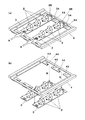
図1及び図2は本発明の第1実施形態における部品実装システム1を示している。部品実装システム1は、図3(a),(b)に示す立体形状のワーク2に複数の部品PT(図3(b))を三次元的に実装して立体形状の部品実装体を製造するシステムである。ここでは説明の便宜上、作業者OPから見た部品実装システム1の左右方向をX軸方向とし、前後方向をY軸方向とする。また、上下方向をZ軸方向とする。
(First Embodiment)
1 and 2 show the component mounting system 1 according to the first embodiment of the present invention. The component mounting system 1 manufactures a three-dimensional component mount by three-dimensionally mounting a plurality of component PTs (FIG. 3 (b)) on the three-dimensional workpiece 2 shown in FIGS. 3 (a) and 3 (b). It is a system to do. Here, for convenience of explanation, the left-right direction of the component mounting system 1 as seen from the operator OP is the X-axis direction, and the front-rear direction is the Y-axis direction. Further, the vertical direction is the Z-axis direction.

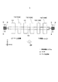
図1において、部品実装システム1は、X軸方向を作業の流れ方向としている。部品実装システム1には、ワーク2を保持するワーク保持体3(図4)が用いられる。ワーク保持体3はワーク2を保持した状態で(図5(a),(b))、キャリア4に載置される(図6)。キャリア4が部品実装システム1の上流側から下流側に搬送される間に、ワーク保持体3に保持されたワーク2には半田や接着剤等の粘性体が供給され、部品PT(図3(b))が実装される。ここではワーク保持体3に保持されるワーク2は複数として説明するが、ワーク2の数は必ずしも複数でなくてもよい。また、キャリア4に載置されるワーク保持体3は複数として説明するが、ワーク保持体3の数は必ずしも複数でなくてもよい。 In FIG. 1, the component mounting system 1 has a work flow direction in the X-axis direction. A work holder 3 (FIG. 4) for holding the work 2 is used in the component mounting system 1. The work holding body 3 is placed on the carrier 4 while holding the work 2 (FIGS. 5A and 5B) (FIG. 6). While the carrier 4 is transported from the upstream side to the downstream side of the component mounting system 1, a viscous body such as solder or an adhesive is supplied to the work 2 held by the work holding body 3, and the component PT (FIG. 3 (FIG. 3). b)) is implemented. Here, the number of works 2 held by the work holder 3 will be described as a plurality, but the number of the works 2 does not necessarily have to be a plurality. Further, although the number of the work holders 3 placed on the carrier 4 will be described as a plurality, the number of the work holders 3 does not necessarily have to be a plurality.

図1及び図2において、部品実装システム1は、上流側から順に、印刷装置10、塗布装置11及び2つの実装装置12(実装装置12A及び実装装置12B)を備えている。印刷装置10と塗布装置11の間と2つの実装装置12の間のそれぞれには姿勢変更装置13(上流側の姿勢変更装置13Aと下流側の姿勢変更装置13B)を備えている。各装置は搬送路14で繋がっている。各装置はコンベアや移載ロボット等の搬送機構を備えており、部品実装システム1は各装置の搬送機構で構成した搬送手段を備えている。言い換えれば、搬送路14は搬送手段によるワーク保持体3の搬送経路である。 In FIGS. 1 and 2, the component mounting system 1 includes a printing device 10, a coating device 11, and two mounting devices 12 (mounting device 12A and mounting device 12B) in this order from the upstream side. A posture changing device 13 (upstream side posture changing device 13A and downstream side posture changing device 13B) is provided between the printing device 10 and the coating device 11 and between the two mounting devices 12, respectively. Each device is connected by a transport path 14. Each device is provided with a transfer mechanism such as a conveyor or a transfer robot, and the component mounting system 1 is provided with a transfer means composed of the transfer mechanism of each device. In other words, the transport path 14 is a transport path for the work holder 3 by the transport means.

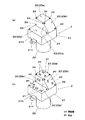
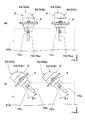
図3(a),(b)に示すように、各ワーク2は、本体部21と、本体部21から延びた円柱状の延出部22を有している。ここでは、図3(a),(b)に示すように、延出部22が下方に延びた姿勢が、ワーク2の基準姿勢であるとする。本体部21には複数の実装面23としての4つの面(第1面23a、第2面23b、第3面23c及び第4面23d)が形成されている。 As shown in FIGS. 3A and 3B, each work 2 has a main body portion 21 and a columnar extending portion 22 extending from the main body portion 21. Here, as shown in FIGS. 3A and 3B, it is assumed that the posture in which the extending portion 22 extends downward is the reference posture of the work 2. The main body 21 is formed with four surfaces (first surface 23a, second surface 23b, third surface 23c, and fourth surface 23d) as a plurality of mounting surfaces 23.

図3(a),(b)において、ワーク2が基準姿勢にあるとき、第1面23aと第3面23cは水平姿勢となる。第3面23cは第1面23aよりも低い高さに位置する。第2面23bは上端が第1面23aに連接した斜面となる。第4面23dは上端が第1面23aに連接し、下端が第3面23cに連接した鉛直面となる。各実装面23には部品PTを電気的に接続するための電極や配線パターン(図示省略)が形成されている。 In FIGS. 3A and 3B, when the work 2 is in the reference posture, the first surface 23a and the third surface 23c are in the horizontal posture. The third surface 23c is located at a lower height than the first surface 23a. The second surface 23b is a slope whose upper end is connected to the first surface 23a. The upper end of the fourth surface 23d is connected to the first surface 23a, and the lower end is connected to the third surface 23c. Electrodes and wiring patterns (not shown) for electrically connecting component PTs are formed on each mounting surface 23.

図3(a),(b)において、各ワーク2の本体部21には、ワーク2が基準姿勢にあるときに水平面内方向(側方)に張り出して延びた姿勢となる2つの耳部21Yが設けられている(図3(a),(b)では、一方の耳部21Yは見えていない)。2つの耳部21Yは延出部22の上下軸に対して対称となる位置に設けられている。各耳部21Yには上下方向に貫通した貫通孔21Hが設けられている。 In FIGS. 3A and 3B, the main body 21 of each work 2 has two ear portions 21Y in a posture in which the work 2 projects in the horizontal plane direction (sideways) when the work 2 is in the reference posture. (In FIGS. 3 (a) and 3 (b), one ear portion 21Y is not visible). The two ear portions 21Y are provided at positions symmetrical with respect to the vertical axis of the extension portion 22. Each selvage 21Y is provided with a through hole 21H penetrating in the vertical direction.

図3(b)に示すように、各実装面23における部品PTの実装箇所には予め半田や接着剤等の粘性体が供給されたうえで、部品PTが実装される。各実装面23には、粘性体の供給時と部品PTの実装時に目安とされる複数の認識マーク24が設けられている(図3(a),(b))。 As shown in FIG. 3B, the component PT is mounted after a viscous body such as solder or an adhesive is supplied in advance to the mounting location of the component PT on each mounting surface 23. Each mounting surface 23 is provided with a plurality of recognition marks 24 as a guide when the viscous body is supplied and when the component PT is mounted (FIGS. 3A and 3B).

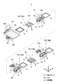
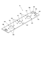
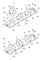
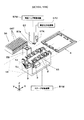
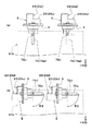
図4において、ワーク保持体3は一の方向に延びた板状の部材から成り、その長手方向に一列に並んだ複数(ここでは3つ)のワーク保持孔31を有している。各ワーク保持孔31はワーク2の延出部22の外径よりもひと回り大きい内径を有している。ワーク保持体3の上面の各ワーク保持孔31の周囲には、複数の突起32が上方に突出して設けられている。各突起32はワーク保持孔31の中心軸に対して対称となる位置に2つずつ、複数組設けられている。ここでは2つ一組の突起32が2組(合計で4つ)、90度ずつずれた位置に設けられている。 In FIG. 4, the work holding body 3 is made of a plate-shaped member extending in one direction, and has a plurality of (here, three) work holding holes 31 arranged in a row in the longitudinal direction thereof. Each work holding hole 31 has an inner diameter slightly larger than the outer diameter of the extending portion 22 of the work 2. A plurality of protrusions 32 are provided so as to project upward around each work holding hole 31 on the upper surface of the work holding body 3. A plurality of sets of each of the protrusions 32 are provided at positions symmetrical with respect to the central axis of the work holding hole 31. Here, two sets of protrusions 32 (four in total) are provided at positions offset by 90 degrees.

図4及び図5(a),(b)において、ワーク保持体3が備える2つの長辺部の一方の端部34側の互いに対向する位置には、一対のくり抜き部33が設けられている。ワーク保持体3の一対のくり抜き部33が設けられた側の端部34には、対キャリア係止孔35が設けられている。ワーク保持体3の長手方向の両端部にはそれぞれ、対ステージ係止孔36が設けられている。 In FIGS. 4 and 5 (a) and 5 (b), a pair of hollowed portions 33 are provided at positions facing each other on one end 34 side of the two long side portions included in the work holder 3. .. A carrier locking hole 35 is provided at the end 34 on the side of the work holder 3 on which the pair of hollowed portions 33 is provided. Anti-stage locking holes 36 are provided at both ends of the work holder 3 in the longitudinal direction.

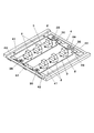
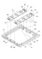
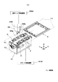
図6、図7及び図8において、キャリア4は2つの対向する縦辺部41と2つの対向する横辺部42を有した矩形の枠体形状に形成されている。2つの横辺部42のそれぞれには、ワーク保持体3の長手方向の両端部を下方から支持する保持体支持片43が設けられている。一方の横辺部42に設けられた保持体支持片43には、ワーク保持体3の対キャリア係止孔35と嵌合する突起部44が上方に延びて形成されている。 In FIGS. 6, 7 and 8, the carrier 4 is formed in a rectangular frame shape having two opposing vertical side portions 41 and two opposing horizontal side portions 42. Each of the two lateral side portions 42 is provided with a holder support piece 43 that supports both ends of the work holder 3 in the longitudinal direction from below. The holding body support piece 43 provided on one of the lateral side portions 42 is formed with a protruding portion 44 extending upward to fit with the carrier locking hole 35 of the work holding body 3.

ワーク2をワーク保持体3に保持させるときには、ワーク2の延出部22をワーク保持孔31に上方から挿通する(図5(a)→図5(b))。このときワーク2の2つの貫通孔21Hにワーク保持体3の2つの突起32が嵌入するようにする。本実施の形態では、ワーク保持体3は一列に並んだ複数(3つ)のワーク保持孔31を有しているので、ワーク保持孔31の数(3つ)の複数のワーク2を一列に並べて保持することができる(図5(a),(b))。なお、ワーク2をワーク保持体3に保持させる手段としては、ワーク保持体3に配置した磁石を突起32に替えて、又は併用で使用してもよい。 When the work 2 is held by the work holding body 3, the extending portion 22 of the work 2 is inserted into the work holding hole 31 from above (FIG. 5 (a) → FIG. 5 (b)). At this time, the two protrusions 32 of the work holder 3 are fitted into the two through holes 21H of the work 2. In the present embodiment, since the work holding body 3 has a plurality of (three) work holding holes 31 arranged in a row, the plurality of works 2 having the number of work holding holes 31 (three) are arranged in a row. It can be held side by side (FIGS. 5 (a) and 5 (b)). As a means for holding the work 2 on the work holding body 3, the magnet arranged on the work holding body 3 may be replaced with the protrusion 32 or used in combination.

本実施の形態では、前述したように、2つの突起32は90度ずつずれて2組設けられているので、ワーク2はワーク保持体3に対し、ワーク保持孔31の上下中心軸回りに、互いに90度ずれた2つの姿勢での取付け方が可能である(図5(a),(b))。以下、図5(a)のようにワーク保持体3に取り付けたときのワーク2の姿勢を「第1の姿勢」と称し、図5(b)のようにワーク保持体3に取り付けたときのワーク2の姿勢を「第2の姿勢」と称する。 In the present embodiment, as described above, since the two protrusions 32 are provided in two sets with a deviation of 90 degrees each, the work 2 is provided with respect to the work holding body 3 around the vertical center axis of the work holding hole 31. It can be mounted in two postures that are 90 degrees apart from each other (FIGS. 5 (a) and 5 (b)). Hereinafter, the posture of the work 2 when it is attached to the work holder 3 as shown in FIG. 5 (a) is referred to as a “first posture”, and when it is attached to the work holder 3 as shown in FIG. 5 (b). The posture of the work 2 is referred to as a "second posture".

ワーク保持体3に「第1の姿勢」で取り付けたワーク2を「第2の姿勢」に姿勢変更するには、先ず、ワーク保持体3に取り付けたワーク2を上昇させて貫通孔21Hをワーク保持体3の2つの突起32から離脱させることによって、ワーク保持体3からワーク2を取り外す。そして、ワーク2を延出部22の中心軸(ワーク保持孔31の上下中心軸)回りに90度回転させた後下降させ、2つの貫通孔21Hが先程とは異なる2つの突起32に嵌入するようにして、ワーク保持体3に取り付ける。ワーク保持体3に「第2の姿勢」で取り付けたワーク2を「第1の姿勢」に姿勢変更する手順も同様である。 In order to change the posture of the work 2 attached to the work holding body 3 in the "first posture" to the "second posture", first, the work 2 attached to the work holding body 3 is raised to form the through hole 21H. The work 2 is removed from the work holding body 3 by separating it from the two protrusions 32 of the holding body 3. Then, the work 2 is rotated 90 degrees around the central axis of the extension portion 22 (the vertical central axis of the work holding hole 31) and then lowered, and the two through holes 21H are fitted into the two protrusions 32 different from the previous ones. In this way, it is attached to the work holder 3. The procedure for changing the posture of the work 2 attached to the work holder 3 in the “second posture” to the “first posture” is also the same.

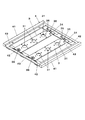
ワーク2を保持したワーク保持体3をキャリア4に載置するときは、ワーク保持体3の長手方向の両端部を2つの保持体支持片43に上方から載置させる(図6)。このとき、ワーク保持体3の対キャリア係止孔35を、キャリア4の突起部44に上方から嵌入させるようにする。このような状態からワーク保持体3をキャリア4に対して持ち上げて、突起部44から対キャリア係止孔35を離脱させたうえで、ワーク保持体3をその長手方向にずらすと(図9(a)中に示す矢印A)、ワーク保持体3が有する一対のくり抜き部33とキャリア4が有する保持体支持片43の端部とを上下に一致した状態となる(図9(a))。このような状態からワーク保持体3をキャリア4に対して相対的に下降させると(図9(b)中に示す矢印B)、ワーク保持体3はキャリア4の下方に引き抜かれ、キャリア4から分離される(図9(b))。 When the work holder 3 holding the work 2 is placed on the carrier 4, both ends of the work holder 3 in the longitudinal direction are placed on the two holder support pieces 43 from above (FIG. 6). At this time, the carrier locking hole 35 of the work holding body 3 is fitted into the protrusion 44 of the carrier 4 from above. From such a state, the work holding body 3 is lifted with respect to the carrier 4, the carrier locking hole 35 is separated from the protrusion 44, and then the work holding body 3 is shifted in the longitudinal direction thereof (FIG. 9 (FIG. 9). The arrow A) shown in a) shows that the pair of hollowed portions 33 of the work holder 3 and the ends of the holder support piece 43 of the carrier 4 are vertically aligned (FIG. 9 (a)). When the work holder 3 is lowered relative to the carrier 4 from such a state (arrow B shown in FIG. 9B), the work holder 3 is pulled out below the carrier 4 and is pulled out from the carrier 4. Separated (Fig. 9 (b)).

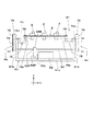
印刷装置10は、図2及び図10に示すように、ワーク2の位置決め機構としての作業ステージ51と、マスク52及びスキージユニット53を備えてワーク2にスクリーン印刷を行う印刷機構54を有している。塗布装置11は、図2及び図11に示すように、ワーク2の位置決め機構としての作業ステージ51と、塗布ヘッド55を備えている。実装装置12(実装装置12A及び実装装置12B)は、図2及び図12に示すように、ワーク2の位置決め機構としての作業ステージ51と、部品供給部56、実装ヘッド57及び部品カメラ58を備えている。印刷装置10が備える作業ステージ51と、塗布装置11が備える作業ステージ51と、実装装置12が備える作業ステージ51の構成は同じである。 As shown in FIGS. 2 and 10, the printing apparatus 10 includes a work stage 51 as a positioning mechanism for the work 2, and a printing mechanism 54 provided with a mask 52 and a squeegee unit 53 to perform screen printing on the work 2. There is. As shown in FIGS. 2 and 11, the coating device 11 includes a working stage 51 as a positioning mechanism for the work 2 and a coating head 55. As shown in FIGS. 2 and 12, the mounting device 12 (mounting device 12A and mounting device 12B) includes a work stage 51 as a positioning mechanism for the work 2, a component supply unit 56, a mounting head 57, and a component camera 58. ing. The configuration of the work stage 51 included in the printing device 10, the work stage 51 included in the coating device 11, and the work stage 51 included in the mounting device 12 is the same.

作業ステージ51は、図10、図11及び図12に示すように、搬送路14の下方に配置されている。作業ステージ51は、ワーク2を保持したワーク保持体3を横向きの(詳細にはX軸方向に延びた)揺動軸YJ回りに揺動させる機構を有している。 The work stage 51 is arranged below the transport path 14, as shown in FIGS. 10, 11 and 12. The work stage 51 has a mechanism for swinging the work holding body 3 holding the work 2 around the swing axis YJ in the lateral direction (specifically, extending in the X-axis direction).

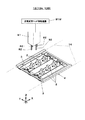
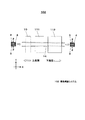
図13及び図14において、作業ステージ51は、ベース体61、揺動モータ62、伝達軸63及び2つの同期駆動機構64を備えている。ベース体61は、水平な水平部61aと、水平部61aのX軸方向の両端部のそれぞれから垂直上方に延びた2つの直立部61bを有している。揺動モータ62は水平部61aの上面に設けられており、出力軸62JをX軸方向に向けている。出力軸62Jの先端には出力軸プーリ62Pが取り付けられている。伝達軸63は水平部61aの上方をX軸方向延びており、その両端は2つの直立部61bを貫通している。伝達軸63には伝達軸プーリ63Pが設けられている。伝達軸プーリ63Pは出力軸プーリ62Pの上方に位置しており、伝達ベルト63Bによって出力軸プーリ62Pと連結されている。 In FIGS. 13 and 14, the work stage 51 includes a base body 61, a swing motor 62, a transmission shaft 63, and two synchronous drive mechanisms 64. The base body 61 has a horizontal horizontal portion 61a and two upright portions 61b extending vertically upward from each of both ends of the horizontal portion 61a in the X-axis direction. The swing motor 62 is provided on the upper surface of the horizontal portion 61a, and the output shaft 62J is directed in the X-axis direction. An output shaft pulley 62P is attached to the tip of the output shaft 62J. The transmission shaft 63 extends above the horizontal portion 61a in the X-axis direction, and both ends thereof penetrate the two upright portions 61b. The transmission shaft 63 is provided with a transmission shaft pulley 63P. The transmission shaft pulley 63P is located above the output shaft pulley 62P and is connected to the output shaft pulley 62P by a transmission belt 63B.

図13及び図14において、2つの同期駆動機構64は2つの直立部61bのそれぞれに設けられている。各同期駆動機構64は直立部61bから外方に突出した伝達軸63の端部に取り付けられた駆動プーリ71と、駆動プーリ71の上方に駆動プーリ71を挟んで配置された2つの従動プーリ72を有している。駆動プーリ71と2つの従動プーリ72はタイミングベルト73によって連結されており、2つの従動プーリ72の中間部には、タイミングベルト73に適度な張力を与えるテンションプーリ74が配置されている。2つの同期駆動機構64の間では、従動プーリ72同士はX軸方向に対向して位置している。 In FIGS. 13 and 14, the two synchronous drive mechanisms 64 are provided in each of the two upright portions 61b. Each synchronous drive mechanism 64 has a drive pulley 71 attached to the end of a transmission shaft 63 projecting outward from the upright portion 61b, and two driven pulleys 72 arranged above the drive pulley 71 with the drive pulley 71 interposed therebetween. have. The drive pulley 71 and the two driven pulleys 72 are connected by a timing belt 73, and a tension pulley 74 that gives an appropriate tension to the timing belt 73 is arranged at an intermediate portion between the two driven pulleys 72. Between the two synchronous drive mechanisms 64, the driven pulleys 72 are located so as to face each other in the X-axis direction.

図14において、各従動プーリ72の回転軸72Jは直立部61bをX軸方向に貫通して2つの直立部61bの間の空間内に突出して延びており、その突出した回転軸72Jの端部には保持体支持部材75が取り付けられている(図13も参照)。保持体支持部材75はアーム部75aを備えており、アーム部75aは従動プーリ72の回転軸72Jの軸線である前述の揺動軸YJ回りに上下面(YZ面)内で揺動する。 In FIG. 14, the rotating shaft 72J of each driven pulley 72 penetrates the upright portion 61b in the X-axis direction and protrudes into the space between the two upright portions 61b, and the end portion of the protruding rotating shaft 72J. A retainer support member 75 is attached to the body (see also FIG. 13). The holding body support member 75 includes an arm portion 75a, and the arm portion 75a swings in the upper and lower surfaces (YZ plane) around the above-mentioned swing shaft YJ, which is the axis of the rotation shaft 72J of the driven pulley 72.

揺動モータ62が出力軸62Jを回転させると出力軸プーリ62P、伝達ベルト63B、伝達軸プーリ63Pを介して伝達軸63がX軸回りに回転する。これにより2つの同期駆動機構64では駆動プーリ71が同期して回転し、2つのタイミングベルト73を介して4つの従動プーリ72が同期して同方向に回転するまた、これにより4つのアーム部75aは同期して同方向に揺動する。4つの保持体支持部材75は予めアーム部75a同士が互いに平行になるように取り付けられているため、伝達軸63が回転すると、X軸方向に対向する2つのアーム部75aは同期して揺動軸YJ回りに揺動する。これにより4つのアーム部75aは、揺動モータ62の出力軸62Jの回転方向に応じた方向に同期して互いに平行姿勢を支持した状態で揺動する。 When the swing motor 62 rotates the output shaft 62J, the transmission shaft 63 rotates about the X axis via the output shaft pulley 62P, the transmission belt 63B, and the transmission shaft pulley 63P. As a result, in the two synchronous drive mechanisms 64, the drive pulley 71 rotates synchronously, and the four driven pulleys 72 rotate synchronously in the same direction via the two timing belts 73, whereby the four arm portions 75a Swings in the same direction in synchronization. Since the four holding body support members 75 are attached in advance so that the arm portions 75a are parallel to each other, when the transmission shaft 63 rotates, the two arm portions 75a facing in the X-axis direction swing in synchronization with each other. It swings around the axis YJ. As a result, the four arm portions 75a swing in a state of supporting parallel postures in synchronization with the direction corresponding to the rotation direction of the output shaft 62J of the swing motor 62.

図13及び図14において、4つのアーム部75aの先端部には支持突起76が上方に突出して設けられている。X軸方向に対向する2つの支持突起76の間の距離は、ワーク保持体3が有する2つの対ステージ係止孔36の間の距離と合致している。このため、作業ステージ51が備える2つの支持突起76にワーク保持体3の2つの対ステージ係止孔36を上方から嵌入させると、ワーク保持体3の両端部を2つのアーム部75aに支持させることができる(図13及び図14)。このときワーク保持体3はその長手方向が揺動軸YJの延びる方向と一致するので、ワーク保持体3は、複数のワーク2を揺動軸YJの延びる方向に並んだ状態に保持した状態となる。なお、必要であれば、アーム部75aに真空吸引用の穴や電磁石を設け、負圧や磁力によってワーク保持体3を保持するようにしてもよい。 In FIGS. 13 and 14, support protrusions 76 are provided at the tips of the four arm portions 75a so as to project upward. The distance between the two support protrusions 76 facing each other in the X-axis direction matches the distance between the two anti-stage locking holes 36 of the work holder 3. Therefore, when the two anti-stage locking holes 36 of the work holding body 3 are fitted into the two supporting protrusions 76 provided on the work stage 51 from above, both end portions of the work holding body 3 are supported by the two arm portions 75a. Can be done (FIGS. 13 and 14). At this time, since the longitudinal direction of the work holding body 3 coincides with the extending direction of the swing axis YJ, the work holding body 3 holds a plurality of works 2 in a state of being arranged side by side in the extending direction of the swing axis YJ. Become. If necessary, the arm portion 75a may be provided with a hole for vacuum suction or an electromagnet to hold the work holding body 3 by negative pressure or magnetic force.

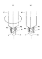
ワーク2を保持したワーク保持体3をアーム部75aに支持させた状態で伝達軸63をX軸回りに回転させると、X軸方向に対向する2つのアーム部75aが同期して横向きの揺動軸YJ回りに揺動する。「第1の姿勢」(図5(a))でワーク保持体3に保持されたワーク2は、第1面23aが水平になる姿勢(図15(a))と、第2面23bが水平になる姿勢(図15(b))とをとることができる。同様に、「第2の姿勢」(図5(b))でワーク保持体3に保持されたワーク2は、第3面23cが水平になる姿勢(図16(a))と、第4面23dが水平になる姿勢(図16(b))とをとることができる。 When the transmission shaft 63 is rotated around the X-axis while the work-holding body 3 holding the work 2 is supported by the arm portion 75a, the two arm portions 75a facing in the X-axis direction swing laterally in synchronization with each other. It swings around the axis YJ. The work 2 held by the work holder 3 in the "first posture" (FIG. 5 (a)) has a posture in which the first surface 23a is horizontal (FIG. 15 (a)) and the second surface 23b is horizontal. It is possible to take a posture of becoming (FIG. 15 (b)). Similarly, the work 2 held by the work holder 3 in the “second posture” (FIG. 5 (b)) has a posture in which the third surface 23c is horizontal (FIG. 16 (a)) and the fourth surface. It is possible to take a posture in which 23d is horizontal (FIG. 16B).

図10、図11及び図12において、印刷装置10、塗布装置11及び実装装置12のそれぞれにはステージ移動機構51Mが設けられている。これらステージ移動機構51Mは作業ステージ51を昇降移動させるとともに、水平方向に移動させる。 In FIGS. 10, 11 and 12, each of the printing device 10, the coating device 11, and the mounting device 12 is provided with a stage moving mechanism 51M. These stage moving mechanisms 51M move the work stage 51 up and down and move it in the horizontal direction.

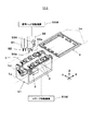
図10において、本実施の形態では、印刷装置10のマスク52には、各ワーク2が備える4つの実装面23のうちの第1面23aに対応する単一若しくは複数の第1マスク開口(図示省略)から成る第1パターン52aと、第2面23bに対応する単一若しくは複数の第2マスク開口(図示省略)から成る第2パターン52bが形成されている。印刷装置10のスキージユニット53は、ユニット移動機構53MによってY軸方向に移動されるベース部53Bと、ベース部53Bに設けられたスキージ53Sと、スキージ53Sをベース部53Bに対して昇降させるスキージ昇降部53Lを備えている。本実施の形態では、2つのスキージ53SがY軸方向に対向して配置されており、スキージ昇降部53Lは、2つのスキージ53Sをベース部53Bに対して個別に昇降させる。 In FIG. 10, in the present embodiment, the mask 52 of the printing apparatus 10 has a single or a plurality of first mask openings (not shown) corresponding to the first surface 23a of the four mounting surfaces 23 included in each work 2. A first pattern 52a made of (omitted) and a second pattern 52b made of a single or a plurality of second mask openings (not shown) corresponding to the second surface 23b are formed. The squeegee unit 53 of the printing device 10 has a base portion 53B that is moved in the Y-axis direction by the unit moving mechanism 53M, a squeegee 53S provided on the base portion 53B, and a squeegee elevating / lowering that raises and lowers the squeegee 53S with respect to the base portion 53B. The unit 53L is provided. In the present embodiment, the two squeegees 53S are arranged so as to face each other in the Y-axis direction, and the squeegee elevating section 53L raises and lowers the two squeegees 53S individually with respect to the base portion 53B.

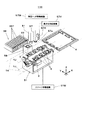
図11において、塗布装置11が備える塗布ヘッド55は、半田を吐出する半田塗布ノズル55aと、接着剤を吐出する接着剤塗布ノズル55bを備えており、半田と接着剤を選択的に吐出して各実装面23に塗布することができる。塗布ヘッド55は塗布ヘッド移動機構55Mによって水平面内方向に移動される。図11において、塗布装置11は撮像光軸を下方に向けた塗布ヘッド認識カメラ55Kを備えている。塗布ヘッド認識カメラ55Kは塗布ヘッド55に取り付けられており、塗布ヘッド55と一体に水平方向へ移動される。 In FIG. 11, the coating head 55 included in the coating device 11 includes a solder coating nozzle 55a for discharging solder and an adhesive coating nozzle 55b for discharging adhesive, and selectively discharges solder and adhesive. It can be applied to each mounting surface 23. The coating head 55 is moved in the horizontal plane by the coating head moving mechanism 55M. In FIG. 11, the coating device 11 includes a coating head recognition camera 55K with the imaging optical axis directed downward. The coating head recognition camera 55K is attached to the coating head 55 and is moved in the horizontal direction integrally with the coating head 55.

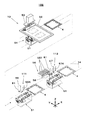
図12において、実装装置12が備える部品供給部56は、ここでは複数のテープフィーダ56Tから成っている。各テープフィーダ56Tは、搬送路14側に開口した部品供給口に部品PTを供給する。実装ヘッド57は下方に延びた複数の吸着ノズル57aと実装ヘッド認識カメラ57Kを備えている。実装ヘッド57は実装ヘッド移動機構57Mによって水平面内方向に移動され、ワーク2に設けられた前述の認識マーク24を認識する。 In FIG. 12, the component supply unit 56 included in the mounting device 12 is composed of a plurality of tape feeders 56T here. Each tape feeder 56T supplies the component PT to the component supply port opened on the transport path 14 side. The mounting head 57 includes a plurality of suction nozzles 57a extending downward and a mounting head recognition camera 57K. The mounting head 57 is moved in the horizontal plane by the mounting head moving mechanism 57M, and recognizes the above-mentioned recognition mark 24 provided on the work 2.

実装ヘッド57が備える各吸着ノズル57aは、実装ヘッド57に設けられた図示しないノズル駆動機構によって上下方向に移動されるとともに、上下軸回りに回転される。図12において、実装ヘッド57は真空圧供給機構57Vと繋がっている。真空圧供給機構57Vから実装ヘッド57に真空圧が供給されると、各吸着ノズル57aの下端に真空吸着力が発生する。実装ヘッド57は部品供給部56が供給する部品PTを各吸着ノズル57aに吸着させて部品PTをピックアップする。実装ヘッド認識カメラ57Kは撮像光軸を下方に向けており、実装ヘッド57と一体に水平方向に移動して、ワーク2に設けられた認識マーク24を認識する。 Each suction nozzle 57a included in the mounting head 57 is moved in the vertical direction by a nozzle drive mechanism (not shown) provided on the mounting head 57, and is rotated around the vertical axis. In FIG. 12, the mounting head 57 is connected to the vacuum pressure supply mechanism 57V. When the vacuum pressure is supplied from the vacuum pressure supply mechanism 57V to the mounting head 57, a vacuum suction force is generated at the lower end of each suction nozzle 57a. The mounting head 57 sucks the component PT supplied by the component supply unit 56 to each suction nozzle 57a and picks up the component PT. The mounting head recognition camera 57K has the imaging optical axis directed downward, and moves horizontally together with the mounting head 57 to recognize the recognition mark 24 provided on the work 2.

図12において、部品カメラ58は搬送路14と部品供給部56の間に撮像光軸を上方に向けた状態で設けられている。部品カメラ58は実装ヘッド57がピックアップした部品PTを認識する。 In FIG. 12, the component camera 58 is provided between the transport path 14 and the component supply unit 56 with the imaging optical axis directed upward. The component camera 58 recognizes the component PT picked up by the mounting head 57.

各吸着ノズル57aは実装ヘッド57に設けられた図示しないノズル駆動機構によって上下方向に移動されるとともに上下軸回りに回転される。実装ヘッド57には真空圧供給機構57Vが繋がっており、真空圧供給機構57Vから実装ヘッド57に真空圧が供給されると、各吸着ノズル57aの下端に真空吸着力が発生する。実装ヘッド57は部品供給部56が供給する部品PTを各吸着ノズル57aに吸着させて部品PTをピックアップする。実装ヘッド認識カメラ57Kは撮像光軸を下方に向けており、実装ヘッド57と一体に水平方向に移動する。 Each suction nozzle 57a is moved in the vertical direction and rotated around the vertical axis by a nozzle drive mechanism (not shown) provided on the mounting head 57. A vacuum pressure supply mechanism 57V is connected to the mounting head 57, and when vacuum pressure is supplied from the vacuum pressure supply mechanism 57V to the mounting head 57, a vacuum suction force is generated at the lower end of each suction nozzle 57a. The mounting head 57 sucks the component PT supplied by the component supply unit 56 to each suction nozzle 57a and picks up the component PT. The mounting head recognition camera 57K has the image pickup optical axis directed downward, and moves horizontally together with the mounting head 57.

図2及び図17において、姿勢変更装置13(姿勢変更装置13A及び姿勢変更装置13B)は、姿勢変更ヘッド81を備えている。図18(a),(b)にも示すように、姿勢変更ヘッド81は複数のフィンガ82を備えている。姿勢変更ヘッド81は、姿勢変更ヘッド移動機構81M(図17)によって水平面内方向に移動される。 In FIGS. 2 and 17, the posture changing device 13 (posture changing device 13A and posture changing device 13B) includes a posture changing head 81. As shown in FIGS. 18A and 18B, the posture change head 81 includes a plurality of fingers 82. The attitude change head 81 is moved in the horizontal plane by the attitude change head movement mechanism 81M (FIG. 17).

姿勢変更ヘッド81は、ワーク保持体3に保持されたワーク2を複数のフィンガ82によって把持し、持ち上げる。これによりワーク2の2つの貫通孔21Hがワーク保持体3の2つの突起32から離脱したら、姿勢変更ヘッド81は上下軸回りに回転して、ワーク2を延出部22の軸芯回りに(すなわちワーク保持孔31の上下中心軸回りに)90度回転させる(図18(a)→図18(b))。そして、ワーク2を下降させ、2つの貫通孔21Hが先程とは異なる2つの突起32に嵌入するようにする。これによりワーク保持体3に対するワーク2の姿勢が変更された状態となる。このように本実施の形態において、姿勢変更ヘッド81は、ワーク2のワーク保持体3における姿勢を変更する姿勢変更手段となっている。 The posture change head 81 grips the work 2 held by the work holding body 3 by the plurality of fingers 82 and lifts the work 2. As a result, when the two through holes 21H of the work 2 are separated from the two protrusions 32 of the work holder 3, the posture change head 81 rotates around the vertical axis to move the work 2 around the axis of the extension portion 22 ( That is, it is rotated 90 degrees (around the vertical center axis of the work holding hole 31) (FIG. 18 (a) → FIG. 18 (b)). Then, the work 2 is lowered so that the two through holes 21H are fitted into the two protrusions 32 different from the previous ones. As a result, the posture of the work 2 with respect to the work holder 3 is changed. As described above, in the present embodiment, the posture changing head 81 is a posture changing means for changing the posture of the work holding body 3 of the work 2.

次に、第1実施形態における部品実装システム1が行う部品実装作業の流れを説明する。第1実施形態における部品実装システム1では、先ず、印刷装置10により各ワーク2に対する粘性体の印刷作業を行った後に塗布装置11による各ワーク2に対する塗布作業を行い、次いで、2つの実装装置12(実装装置12A及び実装装置12B)による各ワーク2に対する部品PTの実装作業を行う。 Next, the flow of the component mounting work performed by the component mounting system 1 in the first embodiment will be described. In the component mounting system 1 of the first embodiment, first, the printing device 10 performs the printing work of the viscous material on each work 2, then the coating device 11 performs the coating work on each work 2, and then the two mounting devices 12 The component PT is mounted on each work 2 by (mounting device 12A and mounting device 12B).

部品実装作業では先ず、複数(ここでは3つ)のワーク2が「第1の姿勢」(図5(a))になるように取り付けられた2つのワーク保持体3が用意される。そして、これら2つのワーク保持体3が載置されたキャリア4を搬送路14が搬送し、印刷装置10が備える作業ステージ51の上方の印刷作業位置に位置される。 In the component mounting work, first, two work holders 3 are prepared so that a plurality of (three in this case) works 2 are attached so as to be in the “first posture” (FIG. 5 (a)). Then, the carrier 4 on which these two work holders 3 are placed is conveyed by the transfer path 14, and is positioned at the printing work position above the work stage 51 included in the printing device 10.

2つのワーク保持体3が印刷装置10の印刷作業位置に位置したら、ステージ移動機構51Mが作動して作業ステージ51を上昇させ、作業ステージ51が備える4つの支持突起76を2つのワーク保持体3それぞれが備える2つの対ステージ係止孔36に下方から嵌入させる。そして、作業ステージ51は更に上昇して2つのワーク保持体3を持ち上げ、2つのワーク保持体3をキャリア4から離間させる。 When the two work holders 3 are located at the printing work positions of the printing device 10, the stage moving mechanism 51M operates to raise the work stage 51, and the four support protrusions 76 included in the work stage 51 are provided to the two work holders 3. It is fitted into the two anti-stage locking holes 36 provided for each from below. Then, the work stage 51 further rises to lift the two work holders 3 and separate the two work holders 3 from the carrier 4.

2つのワーク保持体3がキャリア4から離間したら、搬送路14がキャリア4をわずかにX軸方向に移動させ、2つのワーク保持体3をキャリア4に対してX軸方向に相対移動させた後(図9(a)中に示す矢印A)、印刷装置10のステージ移動機構51Mが作業ステージ51を下降させる(図9(b)中に示す矢印B)。これにより2つのワーク保持体3がキャリア4の下方に引き抜かれ(図9(b))、2つのワーク保持体3はキャリア4から分離する。2つのワーク保持体3がキャリア4から分離したら、搬送路14はキャリア4をX軸方向に移動させて、キャリア4を作業ステージ51から退避させて待機状態にする(図10)。 After the two work holders 3 are separated from the carrier 4, the transport path 14 slightly moves the carrier 4 in the X-axis direction and then moves the two work holders 3 relative to the carrier 4 in the X-axis direction. (Arrow A shown in FIG. 9A), the stage moving mechanism 51M of the printing apparatus 10 lowers the work stage 51 (arrow B shown in FIG. 9B). As a result, the two work holders 3 are pulled out below the carrier 4 (FIG. 9B), and the two work holders 3 are separated from the carrier 4. When the two work holders 3 are separated from the carrier 4, the transport path 14 moves the carrier 4 in the X-axis direction and retracts the carrier 4 from the work stage 51 to put it in a standby state (FIG. 10).

キャリア4が待機状態になったら、印刷装置10のステージ移動機構51Mが作業ステージ51を上昇させる。この状態では各ワーク2の第1面23aが水平姿勢となっており、粘性体が印刷される所定の被作業方向である上方を向いているので(図15(a))、印刷装置10は先ず、各ワーク2の第1面23aに粘性体を印刷する。 When the carrier 4 is in the standby state, the stage moving mechanism 51M of the printing device 10 raises the work stage 51. In this state, the first surface 23a of each work 2 is in a horizontal posture and faces upward, which is a predetermined working direction in which the viscous body is printed (FIG. 15A). First, a viscous material is printed on the first surface 23a of each work 2.

印刷装置10により各ワーク2の第1面23aに粘性体を印刷するには、先ず、ステージ移動機構51Mが作業ステージ51を移動させ、2つのワーク保持体3のそれぞれに保持された各ワーク2の第1面23aをマスク52の第1パターン52aの下方に位置させる。各ワーク2の第1面23aがマスク52の第1パターン52aの下方に位置したら、ステージ移動機構51Mが作業ステージ51を上昇させ、各ワーク2の第1面23aをマスク52の下面に接触させて位置合わせする。 In order to print the viscous body on the first surface 23a of each work 2 by the printing device 10, first, the stage moving mechanism 51M moves the work stage 51, and each work 2 held by each of the two work holding bodies 3 The first surface 23a of the above is positioned below the first pattern 52a of the mask 52. When the first surface 23a of each work 2 is located below the first pattern 52a of the mask 52, the stage moving mechanism 51M raises the work stage 51 and brings the first surface 23a of each work 2 into contact with the lower surface of the mask 52. To align.

各ワーク2の第1面23aがマスク52の下面に接触したら、スキージ昇降部53Lが一方のスキージ53Sを下降させてマスク52に当接させ、Y軸方向に移動させる。これによりスキージ53Sはマスク52上を摺動し、予めマスク52の上面に供給されていた粘性体(図10において符号Pstで示す)がマスク52上で掻き寄せられることによって第1パターン52aの第1マスク開口に充填され、これにより各ワーク2の第1面23aに粘性体が印刷される。各ワーク2の第1面23aに粘性体が印刷されたら、スキージ昇降部53Lがスキージ53Sを上昇させたうえで、ステージ移動機構51Mが作業ステージ51を下降させ、各ワーク2の第1面23aをマスク52の下面から離間させる。これにより印刷装置10による各ワーク2の第1面23aへの粘性体のスクリーン印刷が終了する。 When the first surface 23a of each work 2 comes into contact with the lower surface of the mask 52, the squeegee elevating portion 53L lowers one squeegee 53S to bring it into contact with the mask 52 and moves it in the Y-axis direction. As a result, the squeegee 53S slides on the mask 52, and the viscous body (indicated by the reference numeral Pst in FIG. 10) previously supplied to the upper surface of the mask 52 is scraped onto the mask 52 to cause the first pattern 52a. One mask opening is filled, whereby a viscous body is printed on the first surface 23a of each work 2. When the viscous body is printed on the first surface 23a of each work 2, the squeegee elevating part 53L raises the squeegee 53S, and then the stage moving mechanism 51M lowers the work stage 51, and the first surface 23a of each work 2 is lowered. Is separated from the lower surface of the mask 52. As a result, the screen printing of the viscous material on the first surface 23a of each work 2 by the printing device 10 is completed.

印刷装置10が各ワーク2の第1面23aに粘性体を印刷したら、揺動モータ62が作動して2つの同期駆動機構64を駆動し、2つのワーク保持体3をそれぞれ揺動軸YJ回りに揺動させる。このとき2つのワーク保持体3は同期して同方向に同角度(図15(b)中に示す角度θ1)だけ揺動する。これにより2つのワーク保持体3に保持された複数のワーク2は一括して姿勢の調整がなされ、各ワーク2の第2面23bが水平姿勢となって被作業方向(上方)を向く(図15(b))。各ワーク2の第2面23bが被作業方向を向いたら、印刷装置10は各ワーク2の第2面23bに粘性体を印刷する。 When the printing device 10 prints the viscous body on the first surface 23a of each work 2, the swing motor 62 operates to drive the two synchronous drive mechanisms 64, and the two work holders 3 rotate around the swing shaft YJ, respectively. Swing to. At this time, the two work holders 3 swing in the same direction in the same direction by the same angle (angle θ1 shown in FIG. 15B) in synchronization. As a result, the postures of the plurality of works 2 held by the two work holders 3 are adjusted collectively, and the second surface 23b of each work 2 is in a horizontal posture and faces the work direction (upward) (FIG. 15 (b)). When the second surface 23b of each work 2 faces the work direction, the printing apparatus 10 prints the viscous material on the second surface 23b of each work 2.

印刷装置10により各ワーク2の第2面23bに粘性体を印刷するには、第1面23aに対する粘性体の印刷の場合と同様に、先ず、ステージ移動機構51Mが作業ステージ51を移動させ、2つのワーク保持体3のそれぞれに保持された各ワーク2の第2面23bをマスク52の第2パターン52bの下方に位置させる。各ワーク2の第2面23bがマスク52の第2パターン52bの下方に位置したら、ステージ移動機構51Mが作業ステージ51を上昇させ、各ワーク2の第2面23bをマスク52の下面に接触させて位置合わせする。 In order to print the viscous material on the second surface 23b of each work 2 by the printing apparatus 10, first, the stage moving mechanism 51M moves the work stage 51, as in the case of printing the viscous material on the first surface 23a. The second surface 23b of each work 2 held by each of the two work holders 3 is positioned below the second pattern 52b of the mask 52. When the second surface 23b of each work 2 is located below the second pattern 52b of the mask 52, the stage moving mechanism 51M raises the work stage 51 and brings the second surface 23b of each work 2 into contact with the lower surface of the mask 52. To align.

各ワーク2の第2面23bがマスク52の下面に接触したら、スキージ昇降部53Lが他の一方のスキージ53Sを下降させてマスク52に当接させ、Y軸方向に移動させる。これによりスキージ53Sはマスク52上を摺動し、予めマスク52の上面に供給されていた粘性体がマスク52上で掻き寄せられることによって第2パターン52bの第2マスク開口に充填され、これにより各ワーク2の第2面23bに粘性体が印刷される。各ワーク2の第2面23bに粘性体が印刷されたら、スキージ昇降部53Lがスキージ53Sを上昇させたうえで、ステージ移動機構51Mが作業ステージ51を下降させ、各ワーク2の第2面23bをマスク52の下面から離間させる。これにより印刷装置10による各ワーク2の第2面23bへの粘性体のスクリーン印刷が終了する。 When the second surface 23b of each work 2 comes into contact with the lower surface of the mask 52, the squeegee elevating portion 53L lowers the other squeegee 53S to bring it into contact with the mask 52 and moves it in the Y-axis direction. As a result, the squeegee 53S slides on the mask 52, and the viscous body previously supplied to the upper surface of the mask 52 is scraped onto the mask 52 to fill the second mask opening of the second pattern 52b. A viscous material is printed on the second surface 23b of each work 2. When the viscous body is printed on the second surface 23b of each work 2, the squeegee elevating part 53L raises the squeegee 53S, and then the stage moving mechanism 51M lowers the work stage 51, and the second surface 23b of each work 2 is lowered. Is separated from the lower surface of the mask 52. As a result, the screen printing of the viscous material on the second surface 23b of each work 2 by the printing device 10 is completed.

印刷装置10が各ワーク2の第2面23bに粘性体を印刷したら、揺動モータ62が作動して2つのワーク保持体3を逆方向に角度θ1だけ揺動させ、各ワーク2を元の姿勢に戻す。そして、作業ステージ51と搬送路14が前述の手順とは逆の手順で作動し、印刷作業位置に位置したキャリア4に2つのワーク保持体3を載置させる。キャリア4に2つのワーク保持体3が載置されたら搬送路14が作動してキャリア4を下流側に搬送し、2つのワーク保持体3を姿勢変更装置13Aの姿勢変更作業位置に位置させる。 When the printing device 10 prints the viscous material on the second surface 23b of each work 2, the swing motor 62 operates to swing the two work holders 3 in opposite directions by an angle θ1 to bring each work 2 to its original position. Return to posture. Then, the work stage 51 and the transport path 14 operate in the reverse procedure of the above-mentioned procedure, and the two work holders 3 are placed on the carrier 4 located at the printing work position. When the two work holders 3 are placed on the carrier 4, the transport path 14 operates to transport the carrier 4 to the downstream side, and the two work holders 3 are positioned at the posture change work positions of the posture change device 13A.

2つのワーク保持体3が姿勢変更装置13Aの姿勢変更作業位置に位置したら、姿勢変更装置13Aの姿勢変更ヘッド81が作動し、2つのワーク保持体3に保持された各ワーク2の姿勢を「第1の姿勢」(図5(a))から「第2の姿勢」(図5(b))に変更する。そして、2つのワーク保持体3が保持する全てのワーク2の姿勢変更が終了したら、搬送路14はキャリア4を下流側に搬送し、2つのワーク保持体3を、塗布装置11が備える作業ステージ51の上方の塗布作業位置に位置させる。2つのワーク保持体3が塗布装置11の塗布作業位置に位置したら、塗布装置11は、2つのワーク保持体3をキャリア4から離間させてキャリア4を待機状態にする(図11)。 When the two work holding bodies 3 are positioned at the posture changing working positions of the posture changing device 13A, the posture changing head 81 of the posture changing device 13A is activated, and the posture of each work 2 held by the two work holding bodies 3 is changed to ". The "first posture" (FIG. 5 (a)) is changed to the "second posture" (FIG. 5 (b)). Then, when the posture changes of all the works 2 held by the two work holders 3 are completed, the transport path 14 conveys the carrier 4 to the downstream side, and the work stage provided with the two work holders 3 by the coating device 11. It is located at the coating work position above 51. When the two work holders 3 are located at the coating work positions of the coating device 11, the coating device 11 separates the two work holders 3 from the carrier 4 and puts the carrier 4 in a standby state (FIG. 11).

キャリア4が待機状態になったら、塗布装置11のステージ移動機構51Mが作業ステージ51を上昇させる。この状態では各ワーク2の第3面23cが水平姿勢となって被作業方向(上方)を向いているので(図16(a))、塗布装置11の塗布ヘッド55は先ず、各ワーク2の第3面23cに粘性体を塗布する。塗布装置11の塗布ヘッド55が各ワーク2の第3面23cに粘性体を塗布したら、揺動モータ62が作動して2つの同期駆動機構64を駆動し、2つのワーク保持体3をそれぞれ揺動軸YJ回りに揺動させる。このとき2つのワーク保持体3は同期して同方向に同角度(図16(b)中に示す角度θ2)だけ揺動する。これにより2つのワーク保持体3に保持された複数のワーク2は一括して姿勢の調整がなされ、各ワーク2の第4面23dが水平姿勢となって被作業方向を向く(図16(b))。各ワーク2の第4面23dが被作業方向を向いたら、塗布ヘッド55は各ワーク2の第4面23dに粘性体を塗布する。 When the carrier 4 is in the standby state, the stage moving mechanism 51M of the coating device 11 raises the working stage 51. In this state, the third surface 23c of each work 2 is in a horizontal posture and faces the working direction (upward) (FIG. 16A). Therefore, the coating head 55 of the coating device 11 first of each work 2. A viscous material is applied to the third surface 23c. When the coating head 55 of the coating device 11 coats the viscous body on the third surface 23c of each work 2, the swing motor 62 operates to drive the two synchronous drive mechanisms 64 and swing the two work holders 3, respectively. Swing around the moving axis YJ. At this time, the two work holders 3 swing in the same direction in the same direction by the same angle (angle θ2 shown in FIG. 16B) in synchronization. As a result, the postures of the plurality of works 2 held by the two work holders 3 are adjusted collectively, and the fourth surface 23d of each work 2 becomes a horizontal posture and faces the work direction (FIG. 16 (b). )). When the fourth surface 23d of each work 2 faces the work direction, the coating head 55 applies the viscous body to the fourth surface 23d of each work 2.

塗布装置11の塗布ヘッド55が各ワーク2の第4面23dに粘性体を塗布したら、揺動モータ62が作動して2つのワーク保持体3を逆方向に角度θ2だけ揺動させ、各ワーク2を元の姿勢に戻す。そして、作業ステージ51と搬送路14が逆の手順で作動し、塗布作業位置に位置したキャリア4に2つのワーク保持体3を載置させる。キャリア4に2つのワーク保持体3が載置されたら搬送路14が作動してキャリア4を下流側に搬送し、2つのワーク保持体3を実装装置12Aが備える作業ステージ51の上方の実装作業位置に位置させる。 When the coating head 55 of the coating device 11 coats the viscous body on the fourth surface 23d of each work 2, the swing motor 62 operates to swing the two work holders 3 in opposite directions by an angle θ2, and each work. Return 2 to its original position. Then, the work stage 51 and the transport path 14 operate in the reverse procedure, and the two work holders 3 are placed on the carrier 4 located at the coating work position. When the two work holders 3 are mounted on the carrier 4, the transport path 14 operates to transport the carrier 4 to the downstream side, and the two work holders 3 are mounted on the work stage 51 above the work stage 51 provided by the mounting device 12A. Position it.

2つのワーク保持体3が実装装置12Aの実装作業位置に位置したら、実装装置12Aは塗布装置11と同様の動作によって2つのワーク保持体3をキャリア4から引き抜き、キャリア4を待機状態にする(図12)。キャリア4が待機状態になったら、実装装置12Aのステージ移動機構51Mが作業ステージ51を上昇させる。この状態では各ワーク2の第3面23cが水平姿勢となっており、被作業方向(上方)を向いているので(図16(a))、実装装置12Aの実装ヘッド57は先ず、各ワーク2の第3面23cに部品PTを実装する。 When the two work holders 3 are located at the mounting work positions of the mounting device 12A, the mounting device 12A pulls out the two work holders 3 from the carrier 4 by the same operation as the coating device 11, and puts the carrier 4 in a standby state (the carrier 4 is put into a standby state). FIG. 12). When the carrier 4 is in the standby state, the stage moving mechanism 51M of the mounting device 12A raises the work stage 51. In this state, the third surface 23c of each work 2 is in a horizontal posture and faces the working direction (upward) (FIG. 16A). Therefore, the mounting head 57 of the mounting device 12A first receives each work. The component PT is mounted on the third surface 23c of 2.

部品PTの実装では、先ず、部品供給部56が部品PTを供給し、実装ヘッド57が吸着ノズル57aにより部品PTをピックアップする。そして、実装ヘッド57は部品カメラ58の上方を通過し、部品カメラ58に各部品PTを認識させる。実装ヘッド57は各部品PTを部品カメラ58に認識させたら、作業ステージ51に保持されたワーク保持体3の上方に移動し、ワーク2の実装面23に部品PTを実装する。 In mounting the component PT, first, the component supply unit 56 supplies the component PT, and the mounting head 57 picks up the component PT by the suction nozzle 57a. Then, the mounting head 57 passes above the component camera 58, and causes the component camera 58 to recognize each component PT. After the component camera 58 recognizes each component PT, the mounting head 57 moves above the work holder 3 held by the work stage 51 and mounts the component PT on the mounting surface 23 of the work 2.

実装装置12Aの実装ヘッド57が各ワーク2の第3面23cに部品PTを実装したら、揺動モータ62が作動して2つの同期駆動機構64を駆動し、2つのワーク保持体3をそれぞれ揺動軸YJ回りに揺動させる。このとき2つのワーク保持体3は同期して同方向に同角度(図16(b)中に示す角度θ2)だけ揺動する。これにより2つのワーク保持体3に保持された複数のワーク2は一括して姿勢の調整がなされ、各ワーク2の第4面23dが水平姿勢となって被作業方向(上方)を向く(図16(b))。各ワーク2の第4面23dが被作業方向を向いたら、実装装置12Aの実装ヘッド57は各ワーク2の第4面23dに部品PTを実装する。 When the mounting head 57 of the mounting device 12A mounts the component PT on the third surface 23c of each work 2, the swing motor 62 operates to drive the two synchronous drive mechanisms 64 and swing the two work holders 3, respectively. Swing around the moving axis YJ. At this time, the two work holders 3 swing in the same direction in the same direction by the same angle (angle θ2 shown in FIG. 16B) in synchronization. As a result, the postures of the plurality of works 2 held by the two work holders 3 are adjusted collectively, and the fourth surface 23d of each work 2 becomes a horizontal posture and faces the work direction (upward) (FIG. 16 (b)). When the fourth surface 23d of each work 2 faces the work direction, the mounting head 57 of the mounting device 12A mounts the component PT on the fourth surface 23d of each work 2.

実装装置12Aの実装ヘッド57が各ワーク2の第4面23dに部品PTを実装したら、揺動モータ62が作動して2つのワーク保持体3を逆方向に角度θ2だけ揺動させ、各ワーク2を元の姿勢に戻す。そして、作業ステージ51と搬送路14が逆の手順で作動し、塗布作業位置に位置したキャリア4に2つのワーク保持体3を載置させる。キャリア4に2つのワーク保持体3が載置されたら搬送路14が作動してキャリア4を下流側に搬送し、2つのワーク保持体3を姿勢変更装置13Bの姿勢変更作業位置に位置させる。 When the mounting head 57 of the mounting device 12A mounts the component PT on the fourth surface 23d of each work 2, the swing motor 62 operates to swing the two work holders 3 in opposite directions by an angle θ2, and each work. Return 2 to its original position. Then, the work stage 51 and the transport path 14 operate in the reverse procedure, and the two work holders 3 are placed on the carrier 4 located at the coating work position. When the two work holders 3 are placed on the carrier 4, the transport path 14 operates to transport the carrier 4 to the downstream side, and the two work holders 3 are positioned at the posture change work positions of the posture change device 13B.

2つのワーク保持体3が姿勢変更装置13Bの姿勢変更作業位置に位置したら、姿勢変更装置13Bは姿勢変更ヘッド81を作動させ、2つのワーク保持体3に保持された各ワーク2の姿勢を「第2の姿勢」(図5(b))から「第1の姿勢」(図5(a))に変更する。そして、2つのワーク保持体3が保持する全てのワーク2の姿勢変更が終了したら、搬送路14はキャリア4を下流側に搬送し、2つのワーク保持体3を、実装装置12Bが備える作業ステージ51の上方の実装作業位置に位置させる。 When the two work holding bodies 3 are located at the posture changing working positions of the posture changing device 13B, the posture changing device 13B operates the posture changing head 81 to change the posture of each work 2 held by the two work holding bodies 3. The "second posture" (FIG. 5 (b)) is changed to the "first posture" (FIG. 5 (a)). Then, when the posture changes of all the works 2 held by the two work holders 3 are completed, the transport path 14 conveys the carrier 4 to the downstream side, and the work stage provided with the two work holders 3 by the mounting device 12B. It is located at the mounting work position above 51.

2つのワーク保持体3が実装装置12Bの実装作業位置に位置したら、実装装置12Bは実装装置12Aと同様の動作によって2つのワーク保持体3をキャリア4から引き抜き、キャリア4を待機状態にする。キャリア4が待機状態になったら、実装装置12Bのステージ移動機構51Mが作業ステージ51を上昇させる。この状態では各ワーク2の第1面23aが水平姿勢となって被作業方向(上方)を向いているので(図15(a))、実装装置12Bの実装ヘッド57は先ず、各ワーク2の第1面23aに部品PTを実装する。 When the two work holders 3 are located at the mounting work positions of the mounting device 12B, the mounting device 12B pulls out the two work holding bodies 3 from the carrier 4 by the same operation as the mounting device 12A, and puts the carrier 4 in the standby state. When the carrier 4 is in the standby state, the stage moving mechanism 51M of the mounting device 12B raises the work stage 51. In this state, since the first surface 23a of each work 2 is in a horizontal posture and faces the working direction (upward) (FIG. 15A), the mounting head 57 of the mounting device 12B first of each work 2. The component PT is mounted on the first surface 23a.

実装装置12Bの実装ヘッド57が各ワーク2の第1面23aに部品PTを実装したら、揺動モータ62が作動して2つの同期駆動機構64を駆動し、2つのワーク保持体3をそれぞれ揺動軸YJ回りに揺動させる。このとき2つのワーク保持体3は同期して同方向に同角度(図15(b)中に示す角度θ1)だけ揺動する。これにより2つのワーク保持体3に保持された複数のワーク2は一括して姿勢の調整がなされ、各ワーク2の第2面23bが水平姿勢となって被作業方向(上方)を向く(図15(b))。各ワーク2の第2面23bが被作業方向を向いたら、実装装置12Bの実装ヘッド57は各ワーク2の第2面23bに部品PTを実装する。 When the mounting head 57 of the mounting device 12B mounts the component PT on the first surface 23a of each work 2, the swing motor 62 operates to drive the two synchronous drive mechanisms 64 and swing the two work holders 3, respectively. Swing around the moving axis YJ. At this time, the two work holders 3 swing in the same direction in the same direction by the same angle (angle θ1 shown in FIG. 15B) in synchronization. As a result, the postures of the plurality of works 2 held by the two work holders 3 are adjusted collectively, and the second surface 23b of each work 2 is in a horizontal posture and faces the work direction (upward) (FIG. 15 (b)). When the second surface 23b of each work 2 faces the work direction, the mounting head 57 of the mounting device 12B mounts the component PT on the second surface 23b of each work 2.

実装装置12Bの実装ヘッド57が各ワーク2の第2面23bに部品PTを実装したら、揺動モータ62が作動して2つのワーク保持体3を逆方向に角度θ1だけ揺動させ、各ワーク2を元の姿勢に戻す。そして、作業ステージ51と搬送路14が逆の手順で作動し、実装作業位置に位置したキャリア4に2つのワーク保持体3を載置させる。キャリア4に2つのワーク保持体3が載置されたら搬送路14が作動してキャリア4を下流側に搬送する。これによりキャリア4の1つ分(ワーク保持体3の2つ分)の複数のワーク2に対する部品実装作業が終了する。 When the mounting head 57 of the mounting device 12B mounts the component PT on the second surface 23b of each work 2, the swing motor 62 operates to swing the two work holders 3 in opposite directions by an angle θ1 to swing each work. Return 2 to its original position. Then, the work stage 51 and the transport path 14 operate in the reverse procedure, and the two work holders 3 are placed on the carrier 4 located at the mounting work position. When the two work holders 3 are placed on the carrier 4, the transport path 14 operates to transport the carrier 4 to the downstream side. As a result, the component mounting work for the plurality of works 2 for one carrier 4 (two for the work holder 3) is completed.

このように、第1実施形態における部品実装システム1において、印刷装置10が備える作業ステージ51は、ワーク2を保持したワーク保持体3を横向きの揺動軸YJ回りに揺動させてワーク2の一の実装面23(第1面23a)が所定の被作業方向を向くようにワーク2を位置決めする位置決め機構となっている。また、印刷装置10が備える印刷機構54は、印刷装置10が備える作業ステージ51(位置決め機構)により被作業方向を向くように位置決めされたワーク2の上記一の実装面23を第1パターン52aに位置合わせして粘性体を印刷するものとなっている。そして、印刷装置10の作業ステージ51は、一の実装面23(第1面23a)に粘性体が印刷された後、ワーク保持体3を揺動軸YJ回りに揺動させてワーク2の他の実装面23(第2面23b)が被作業方向を向くようにワーク2を位置決めし、印刷機構54は、作業ステージ51により被作業方向を向くように位置決めされたワーク2の上記他の実装面23を第2パターン52bに位置合わせして粘性体を印刷するようになっている。 As described above, in the component mounting system 1 of the first embodiment, the work stage 51 included in the printing apparatus 10 swings the work holder 3 holding the work 2 around the lateral swing axis YJ to form the work 2. It is a positioning mechanism that positions the work 2 so that one mounting surface 23 (first surface 23a) faces a predetermined working direction. Further, the printing mechanism 54 included in the printing device 10 uses the first pattern 52a as the first mounting surface 23 of the work 2 positioned so as to face the work direction by the work stage 51 (positioning mechanism) included in the printing device 10. The viscous material is printed by aligning it. Then, in the work stage 51 of the printing apparatus 10, after the viscous body is printed on one mounting surface 23 (first surface 23a), the work holding body 3 is swung around the swing axis YJ to other than the work 2. The work 2 is positioned so that the mounting surface 23 (second surface 23b) of the work 2 faces the work direction, and the printing mechanism 54 mounts the work 2 positioned so as to face the work direction by the work stage 51. The surface 23 is aligned with the second pattern 52b to print the viscous material.

このような構成を有する第1実施形態における部品実装システム1により立体形状を有するワーク2に粘性体を供給して部品PTを実装する部品実装方法では、ワーク2を保持したワーク保持体3を横向きの揺動軸YJ回りに揺動させてワーク2の一の実装面23(第1面23a)が所定の被作業方向を向くようにワーク2を位置決めし(第1の位置決め工程)、その位置決めしたワーク2の上記一の実装面23に粘性体を印刷する(第1の印刷工程)。そして、ワーク保持体3を揺動軸YJ回りに揺動させて一の実装面23(第1面23a)に粘性体が印刷されたワーク2の他の実装面23(第2面23b)が被作業方向を向くようにワーク2を位置決めしたうえで(第2の位置決め工程)、その位置決めしたワーク2の上記他の実装面23に粘性体を印刷する(第2の印刷工程)。 In the component mounting method in which the viscous body is supplied to the work 2 having a three-dimensional shape by the component mounting system 1 in the first embodiment having such a configuration and the component PT is mounted, the work holder 3 holding the work 2 is turned sideways. The work 2 is positioned so that one mounting surface 23 (first surface 23a) of the work 2 faces a predetermined work direction by swinging around the swing axis YJ (first positioning step), and the positioning thereof is performed. A viscous material is printed on the above-mentioned one mounting surface 23 of the work 2 (first printing step). Then, the work holding body 3 is swung around the swing axis YJ, and the other mounting surface 23 (second surface 23b) of the work 2 on which the viscous material is printed on one mounting surface 23 (first surface 23a) is formed. After positioning the work 2 so as to face the work direction (second positioning step), the viscous material is printed on the other mounting surface 23 of the positioned work 2 (second printing step).

(第2実施形態)
次に、本発明の第2実施形態を説明する。図19及び図20は本発明の第2実施形態における部品実装システム102を示している。第2実施形態における部品実装システム102は、上流側から順に、印刷装置10、塗布装置111及び実装装置112を備えている。各装置は、第1実施形態の場合と同様に、搬送路14で繋がっている。
(Second Embodiment)
Next, a second embodiment of the present invention will be described. 19 and 20 show the component mounting system 102 according to the second embodiment of the present invention. The component mounting system 102 in the second embodiment includes a printing device 10, a coating device 111, and a mounting device 112 in this order from the upstream side. Each device is connected by a transport path 14 as in the case of the first embodiment.

第2実施形態における部品実装システム102において、塗布装置111は、第1実施形態の場合と異なり、塗布ヘッド55に姿勢変更手段としての姿勢変更ヘッド81を備えている(図20及び図21)。実装装置112も、実装ヘッド57に姿勢変更ヘッド81を備えている(図20及び図22)。 In the component mounting system 102 of the second embodiment, unlike the case of the first embodiment, the coating device 111 includes a posture changing head 81 as a posture changing means in the coating head 55 (FIGS. 20 and 21). The mounting device 112 also includes a posture changing head 81 on the mounting head 57 (FIGS. 20 and 22).

第2実施形態における部品実装システム102では、印刷装置10の動作は第1実施形態の場合と同様であり、ワーク2の4つの実装面23のうちの第1面23aと第2面23bに粘性体を印刷する。塗布装置111は、印刷装置10から2つのワーク保持体3を作業ステージ51によって受け取ったうえで、塗布ヘッド55に設けられた姿勢変更ヘッド81によって、2つのワーク保持体3に保持された各ワーク2の姿勢を順次、「第1の姿勢」から「第2の姿勢」へ変更する。この状態は、各ワーク2の第3面23cが水平姿勢となって被作業方向(上方)を向いているので(図16(a))、塗布装置111の塗布ヘッド55は先ず、各ワーク2の第3面23cに粘性体を塗布する。塗布装置111の塗布ヘッド55が各ワーク2の第3面23cに粘性体を塗布したら、第1実施形態の場合と同様の要領によって、塗布ヘッド55が、各ワーク2の第4面23dに粘性体を塗布する。そして、第1実施形態の場合と同様の要領によって各ワーク2を元の姿勢に戻す。 In the component mounting system 102 of the second embodiment, the operation of the printing apparatus 10 is the same as that of the first embodiment, and the first surface 23a and the second surface 23b of the four mounting surfaces 23 of the work 2 are viscous. Print the body. The coating device 111 receives the two work holding bodies 3 from the printing device 10 by the work stage 51, and then each work held by the two work holding bodies 3 by the posture changing head 81 provided on the coating head 55. The second posture is sequentially changed from the "first posture" to the "second posture". In this state, since the third surface 23c of each work 2 is in a horizontal posture and faces the working direction (upward) (FIG. 16A), the coating head 55 of the coating device 111 first receives each work 2. A viscous material is applied to the third surface 23c of the above. When the coating head 55 of the coating device 111 coats the viscous body on the third surface 23c of each work 2, the coating head 55 is viscous on the fourth surface 23d of each work 2 in the same manner as in the case of the first embodiment. Apply the body. Then, each work 2 is returned to its original posture in the same manner as in the case of the first embodiment.

塗布装置111は、各ワーク2の第3面23cと第4面23dに粘性体を塗布したら、ワーク保持体3が載置されたキャリア4を下流側の実装装置112に搬出する。実装装置112は塗布装置111よりキャリア4を受け取り、ワーク保持体3を作業ステージ51によって揺動軸YJ回りに揺動させ、第3面23cと第4面23dを順次被作業方向に向けながら、実装ヘッド57により、各ワーク2の第3面23cと第4面23dに順次、部品PTを実装する。 After the viscous body is applied to the third surface 23c and the fourth surface 23d of each work 2, the coating device 111 carries out the carrier 4 on which the work holding body 3 is placed to the mounting device 112 on the downstream side. The mounting device 112 receives the carrier 4 from the coating device 111, swings the work holder 3 around the swing axis YJ by the work stage 51, and while sequentially directing the third surface 23c and the fourth surface 23d toward the work direction. The mounting head 57 sequentially mounts the component PT on the third surface 23c and the fourth surface 23d of each work 2.

実装装置112は、各ワーク2の第3面23cと第4面23dに部品PTを実装したら、実装ヘッド57に設けられた姿勢変更ヘッド81により、各ワーク2のワーク保持体3に対する姿勢を「第2の姿勢」から「第1の姿勢」へ変更する。そして、姿勢を変更したワーク2を保持したワーク保持体3を作業ステージ51によって揺動軸YJ回りに揺動させ、第1面23aと第2面23bを順次被作業方向に向けながら、実装ヘッド57により、各ワーク2の第1面23aと第2面23bに順次、部品PTを実装する。 When the mounting device 112 mounts the component PT on the third surface 23c and the fourth surface 23d of each work 2, the posture changing head 81 provided on the mounting head 57 sets the posture of each work 2 with respect to the work holder 3. Change from "second posture" to "first posture". Then, the work holding body 3 holding the work 2 whose posture has been changed is swung around the swing shaft YJ by the work stage 51, and the mounting head is while the first surface 23a and the second surface 23b are sequentially directed in the working direction. The component PT is sequentially mounted on the first surface 23a and the second surface 23b of each work 2 according to the method 57.

このように、第2実施形態における部品実装システム102においても、第1実施形態の場合と同様に、印刷装置10が備える作業ステージ51は、ワーク2を保持したワーク保持体3を横向きの揺動軸YJ回りに揺動させてワーク2の一の実装面23(第1面23a)が所定の被作業方向を向くようにワーク2を位置決めする位置決め機構となっている。また、印刷装置10が備える印刷機構54は、印刷装置10が備える作業ステージ51(位置決め機構)により被作業方向を向くように位置決めされたワーク2の上記一の実装面23に粘性体を印刷するものとなっている。そして、印刷装置10の作業ステージ51は、一の実装面23(第1面23a)に粘性体が印刷された後、ワーク保持体3を揺動軸YJ回りに揺動させてワーク2の他の実装面23(第2面23b)が被作業方向を向くようにワーク2を位置決めし、印刷機構54は、作業ステージ51により被作業方向を向くように位置決めされたワーク2の上記他の実装面23に粘性体を印刷するようになっている。 As described above, also in the component mounting system 102 of the second embodiment, as in the case of the first embodiment, the work stage 51 included in the printing device 10 swings the work holder 3 holding the work 2 sideways. It is a positioning mechanism that positions the work 2 so that one mounting surface 23 (first surface 23a) of the work 2 faces a predetermined work direction by swinging around the axis YJ. Further, the printing mechanism 54 included in the printing device 10 prints a viscous body on the one mounting surface 23 of the work 2 positioned so as to face the work direction by the work stage 51 (positioning mechanism) included in the printing device 10. It has become a thing. Then, in the work stage 51 of the printing apparatus 10, after the viscous body is printed on one mounting surface 23 (first surface 23a), the work holding body 3 is swung around the swing axis YJ to other than the work 2. The work 2 is positioned so that the mounting surface 23 (second surface 23b) of the work 2 faces the work direction, and the printing mechanism 54 mounts the work 2 positioned so as to face the work direction by the work stage 51. A viscous material is printed on the surface 23.

このような構成を有する第2実施形態における部品実装システム102により立体形状を有するワーク2に粘性体を供給して部品PTを実装する部品実装方法でも、第1実施形態の場合と同様に、ワーク2を保持したワーク保持体3を横向きの揺動軸YJ回りに揺動させてワーク2の一の実装面23(第1面23a)が所定の被作業方向を向くようにワーク2を位置決めし(第1の位置決め工程)、その位置決めしたワーク2の上記一の実装面23に粘性体を印刷する(第1の印刷工程)。そして、ワーク保持体3を揺動軸YJ回りに揺動させて一の実装面23(第1面23a)に粘性体が印刷されたワーク2の他の実装面23(第2面23b)が被作業方向を向くようにワーク2を位置決めしたうえで(第2の位置決め工程)、その位置決めしたワーク2の上記他の実装面23に粘性体を印刷する(第2の印刷工程)。 The component mounting method in which the viscous material is supplied to the work 2 having a three-dimensional shape by the component mounting system 102 in the second embodiment having such a configuration to mount the component PT is also the same as in the case of the first embodiment. The work holding body 3 holding 2 is swung around the lateral swing axis YJ to position the work 2 so that one mounting surface 23 (first surface 23a) of the work 2 faces a predetermined work direction. (First positioning step), the viscous body is printed on the above-mentioned one mounting surface 23 of the positioned work 2 (first printing step). Then, the work holding body 3 is swung around the swing axis YJ, and the other mounting surface 23 (second surface 23b) of the work 2 on which the viscous material is printed on one mounting surface 23 (first surface 23a) is formed. After positioning the work 2 so as to face the work direction (second positioning step), the viscous material is printed on the other mounting surface 23 of the positioned work 2 (second printing step).

第2実施形態における部品実装システム102では、第1実施形態における部品実装システム1において、姿勢変更手段である姿勢変更ヘッド81が塗布ヘッド55に設けられた構成となっているため、第1実施形態における部品実装システム1よりも少ない工程でワーク2の第3面23c及び第4面23dに粘性体を塗布することができ、ワーク2への粘性体の供給に要する時間を短縮することができる。また、実装装置112は実装ヘッド57に設けられた姿勢変更ヘッド81によってワーク保持体3におけるワーク2の姿勢変更をでき、一つの実装ヘッド57でワーク2の全ての実装面23に部品PTの実装を行うことができ、部品PTの実装に要する時間も短縮することができる。 In the component mounting system 102 of the second embodiment, the posture changing head 81, which is a posture changing means, is provided in the coating head 55 in the component mounting system 1 of the first embodiment. The viscous body can be applied to the third surface 23c and the fourth surface 23d of the work 2 in less steps than the component mounting system 1 in the above, and the time required for supplying the viscous body to the work 2 can be shortened. Further, the mounting device 112 can change the posture of the work 2 in the work holder 3 by the posture changing head 81 provided on the mounting head 57, and the component PT is mounted on all the mounting surfaces 23 of the work 2 with one mounting head 57. And the time required for mounting the component PT can be shortened.

以上説明したように、第1及び第2実施の形態における部品実装システム1,102では、立体形状を有するワーク2を保持したワーク保持体3を横向きの揺動軸YJ回りに揺動させることによってワーク2が有する一の実装面23(第1面23a)と他の実装面23(第2面23b)をそれぞれ所定の被作業方向に向けることができる。このため、立体形状を有するワーク2の実装面23に対し、簡単な構成で効率よく粘性体の供給を行うことができる。また、本発明の部品実装システム1,102は公知文献のような複雑な構成ではないので製造コストを安価にすることができる。 As described above, in the component mounting systems 1 and 102 in the first and second embodiments, the work holder 3 holding the work 2 having a three-dimensional shape is swung around the lateral swing axis YJ. One mounting surface 23 (first surface 23a) and another mounting surface 23 (second surface 23b) of the work 2 can be oriented in a predetermined working direction. Therefore, the viscous body can be efficiently supplied to the mounting surface 23 of the work 2 having a three-dimensional shape with a simple configuration. Further, since the component mounting systems 1 and 102 of the present invention do not have a complicated configuration as in the publicly known documents, the manufacturing cost can be reduced.

立体形状を有するワークへ粘性体の塗布を簡単な構成で行うことができる部品実装システム及び部品実装方法を提供する。 Provided are a component mounting system and a component mounting method capable of applying a viscous body to a work having a three-dimensional shape with a simple configuration.

1,102 部品実装システム
2 ワーク
3 ワーク保持体
23 実装面
51 作業ステージ(位置決め機構)
52 マスク
52a 第1パターン
52b 第2パターン
53S スキージ
54 印刷機構
YJ 揺動軸
PT 部品
1,102 Parts mounting system 2 Work 3 Work holder 23 Mounting surface 51 Work stage (positioning mechanism)
52 Mask 52a 1st pattern 52b 2nd pattern 53S squeegee 54 Printing mechanism YJ swing shaft PT parts

Claims (12)

立体形状を有するワークの実装面に粘性体を供給して部品を実装する部品実装システムであって、
ワークを保持したワーク保持体を横向きのひとつの揺動軸回りに揺動させて前記ワークの実装面が所定の被作業方向を向くように前記ワークを位置決めする位置決め機構と、
前記位置決め機構により前記被作業方向を向くように位置決めされた前記ワークの前記実装面に粘性体を印刷する印刷機構とを備え
前記ワーク保持体は複数の前記ワークを一列に並べて保持するものであり、前記ひとつの揺動軸は複数の前記ワークの並び方向と同じ方向に延びている部品実装システム。
It is a component mounting system that supplies a viscous body to the mounting surface of a workpiece having a three-dimensional shape and mounts the components.
A positioning mechanism that positions the work by swinging the work holder that holds the work around one lateral swing axis so that the mounting surface of the work faces a predetermined work direction.
A printing mechanism for printing a viscous body on the mounting surface of the work positioned so as to face the work direction by the positioning mechanism is provided .
The work holder is a component mounting system in which a plurality of the works are arranged and held in a row, and the one swing axis extends in the same direction as the arrangement direction of the plurality of the works.
前記印刷機構は、マスク開口から成るパターンが形成されたマスクと、前記マスクの上面の粘性体を前記マスク開口に充填するスキージとを有し、前記位置決め機構により前記被作業方向に向けられた前記実装面を前記パターンに位置合わせする請求項1に記載の部品実装システム。 The printing mechanism has a mask on which a pattern composed of mask openings is formed, and a squeegee that fills the mask openings with a viscous material on the upper surface of the mask, and is oriented in the working direction by the positioning mechanism. The component mounting system according to claim 1, wherein the mounting surface is aligned with the pattern. 立体形状を有する表面に少なくとも一の実装面と他の実装面を含む複数の実装面が形成されたワークの前記複数の実装面に粘性体を供給して部品を実装する部品実装システムであって、
ワークを保持したワーク保持体を横向きのひとつの揺動軸回りに揺動させて前記ワークの前記一の実装面若しくは前記他の実装面が所定の被作業方向を向くように前記ワークを位置決めする位置決め機構と、
前記位置決め機構により前記被作業方向を向くように位置決めされた前記ワークの前記一の実装面若しくは前記他の実装面に粘性体を印刷する印刷機構とを備えた部品実装システム。
A component mounting system in which a viscous material is supplied to the plurality of mounting surfaces of a work in which a plurality of mounting surfaces including at least one mounting surface and another mounting surface are formed on a surface having a three-dimensional shape to mount components. ,
The work holder holding the work is swung around one lateral swing axis to position the work so that the one mounting surface or the other mounting surface of the work faces a predetermined work direction. Positioning mechanism and
A component mounting system including a printing mechanism for printing a viscous body on the one mounting surface or the other mounting surface of the work positioned so as to face the work direction by the positioning mechanism.
前記印刷機構は、前記一の実装面用の第1マスク開口から成る第1パターン及び前記他の実装面用の第2マスク開口から成る第2パターンとが形成されたマスクと、前記マスクの上面の粘性体を前記第1マスク開口及び前記第2マスク開口に充填するスキージとを有し、前記位置決め機構により前記被作業方向に向けられた前記一の実装面を前記第1パターンに位置合わせし、前記位置決め機構により前記被作業方向に向けられた前記他の実装面を前記第2パターンに位置合わせする請求項に記載の部品実装システム。 The printing mechanism includes a mask in which a first pattern composed of a first mask opening for the one mounting surface and a second pattern composed of a second mask opening for the other mounting surface are formed, and an upper surface of the mask. The first mask opening and the squeegee that fills the second mask opening are provided, and the one mounting surface oriented in the working direction by the positioning mechanism is aligned with the first pattern. The component mounting system according to claim 3 , wherein the other mounting surface oriented in the working direction by the positioning mechanism is aligned with the second pattern. 前記ワーク保持体は複数の前記ワークを一列に並べて保持するものであり、前記ひとつの揺動軸は複数の前記ワークの並び方向と同じ方向に延びている請求項に記載の部品実装システム。 The component mounting system according to claim 3 , wherein the work holder holds a plurality of the works side by side in a row, and the one swing axis extends in the same direction as the arrangement direction of the plurality of the works. 前記印刷機構は、前記一の実装面用の第1マスク開口から成る第1パターン及び前記他の実装面用の第2マスク開口から成る第2パターンとが形成されたマスクと、前記マスクの上面の粘性体を前記第1マスク開口及び前記第2マスク開口に充填するスキージとを有しており、前記位置決め機構により前記被作業方向に向けられた複数の前記ワークそれぞれが有する前記一の実装面を前記マスクに形成された複数の前記第1パターンに位置合わせし、前記位置決め機構により前記被作業方向に向けられた複数の前記ワークそれぞれが有する前記他の実装面を前記マスクに形成された複数の前記第2パターンに位置合わせする請求項に記載の部品実装システム。 The printing mechanism includes a mask in which a first pattern composed of a first mask opening for the one mounting surface and a second pattern composed of a second mask opening for the other mounting surface are formed, and an upper surface of the mask. It has the first mask opening and the squeegee that fills the second mask opening, and the one mounting surface of each of the plurality of works oriented in the working direction by the positioning mechanism. Is aligned with the plurality of first patterns formed on the mask, and the other mounting surface of each of the plurality of works oriented in the working direction by the positioning mechanism is formed on the mask. The component mounting system according to claim 5 , wherein the component mounting system is aligned with the second pattern. 立体形状を有するワークの実装面に粘性体を供給して部品を実装する部品実装方法であって、
ワークを保持したワーク保持体を横向きのひとつの揺動軸回りに揺動させて前記ワークの実装面が所定の被作業方向を向くように前記ワークを位置決めする位置決め工程と、
前記位置決め工程で前記被作業方向を向くように位置決めされた前記ワークの前記実装面に粘性体を印刷する印刷工程とを含み、
前記ワーク保持体は複数の前記ワークを一列に並べて保持するものであり、前記ひとつの揺動軸は複数の前記ワークの並び方向と同じ方向に延びている部品実装方法。
It is a component mounting method in which a viscous body is supplied to the mounting surface of a workpiece having a three-dimensional shape to mount the component.
A positioning step in which the work holder holding the work is swung around one lateral swing axis to position the work so that the mounting surface of the work faces a predetermined work direction.
Look including a printing step of printing a viscous material wherein the mounting surface of the workpiece that is positioned to face the working direction in the positioning step,
A component mounting method in which a plurality of the works are arranged and held in a row, and the one swing axis extends in the same direction as the arrangement direction of the plurality of the works.
複数の前記ワークを前記ひとつの揺動軸の延びる方向に一列に並んだ状態で前記ワーク保持体に保持させ、前記位置決め工程は複数の前記ワークの複数の前記実装面を前記被作業方向に向ける請求項に記載の部品実装方法。 A plurality of said workpiece is held by the workpiece holding member in a state arranged in a row in the direction of extension of the pivot shaft of one said, the positioning step directs a plurality of the mounting surfaces of the plurality of the workpiece to the operation target direction The component mounting method according to claim 7. 前記印刷工程は、マスク開口から成るパターンが形成されたマスクと、前記マスクの上面の粘性体を前記マスク開口に充填するスキージとを用いたスクリーン印刷で実施され、前記スクリーン印刷の実施の際に、前記位置決め工程で前記被作業方向に向けられた前記実装面を前記パターンに位置合わせする請求項に記載の部品実装方法。 The printing step is performed by screen printing using a mask on which a pattern composed of mask openings is formed and a squeegee that fills the mask openings with a viscous material on the upper surface of the mask. The component mounting method according to claim 8 , wherein the mounting surface oriented in the work direction in the positioning step is aligned with the pattern. 立体形状を有するワークの実装面に粘性体を供給して部品を実装する部品実装方法であって、
前記ワークを保持したワーク保持体を横向きのひとつの揺動軸回りに揺動させて前記ワークの一の実装面が所定の被作業方向を向くように前記ワークを位置決めする第1の位置決め工程と、
前記第1の位置決め工程で前記被作業方向を向くように位置決めされた前記ワークの前記一の実装面に粘性体を印刷する第1の印刷工程と、
前記ワーク保持体を前記ひとつの揺動軸回りに揺動させて前記一の実装面に粘性体が印刷された前記ワークの他の実装面が前記被作業方向を向くように前記ワークを位置決めする第2の位置決め工程と、
前記第2の位置決め工程で前記被作業方向を向くように位置決めされた前記ワークの前記他の実装面に粘性体を印刷する第2の印刷工程とを含む部品実装方法。
It is a component mounting method in which a viscous body is supplied to the mounting surface of a workpiece having a three-dimensional shape to mount the component.
A first positioning step in which a work holder holding the work is swung around one lateral swing axis to position the work so that one mounting surface of the work faces a predetermined work direction. ,
A first printing step of printing a viscous body on the one mounting surface of the work positioned so as to face the work direction in the first positioning step.
The work holder is swung around the one swinging axis, and the work is positioned so that the other mounting surface of the work on which the viscous body is printed on the one mounting surface faces the work direction. The second positioning process and
A component mounting method including a second printing step of printing a viscous body on the other mounting surface of the work positioned so as to face the work direction in the second positioning step.
複数の前記ワークを前記ひとつの揺動軸の延びる方向に一列に並んだ状態で前記ワーク保持体に保持させ、前記第1の位置決め工程は複数の前記ワークの複数の前記一の実装面を前記被作業方向に向け、前記第2の位置決め工程は複数の前記ワークの複数の前記他の実装面を前記被作業方向に向ける請求項10に記載の部品実装方法。 Wherein a plurality of said workpiece in a state arranged in a row in the direction of extension of the pivot shaft of one said is held by the workpiece holding member, said first positioning step said plurality of said first mounting surface of the plurality of the work The component mounting method according to claim 10 , wherein the second positioning step directs the plurality of other mounting surfaces of the plurality of the workpieces in the working direction. 前記第1の印刷工程及び前記第2の印刷工程は、前記一の実装面用の第1マスク開口から成る第1パターン及び前記他の実装面用の第2マスク開口から成る第2パターンが形成されたマスクと、前記マスクの上面の粘性体を前記第1マスク開口及び前記第2マスク開口に充填するスキージとを用いたスクリーン印刷で実施され、前記スクリーン印刷の実施の際に、前記第1の位置決め工程で前記被作業方向に向けられた前記一の実装面を前記第1パターンに位置合わせし、前記第2の位置決め工程で前記被作業方向に向けられた前記他の実装面を前記第2パターンに位置合わせする請求項10に記載の部品実装方法。 In the first printing step and the second printing step, a first pattern composed of a first mask opening for the one mounting surface and a second pattern composed of a second mask opening for the other mounting surface are formed. The first mask is printed by screen printing using the mask and a squeegee that fills the first mask opening and the second mask opening with a viscous material on the upper surface of the mask. The one mounting surface oriented in the work direction in the positioning step is aligned with the first pattern, and the other mounting surface oriented in the work direction in the second positioning step is aligned with the first pattern. The component mounting method according to claim 10 , wherein the two patterns are aligned with each other.
JP2017055245A 2017-03-22 2017-03-22 Component mounting system and component mounting method Active JP6924924B2 (en)

Priority Applications (1)

Application Number Priority Date Filing Date Title
JP2017055245A JP6924924B2 (en) 2017-03-22 2017-03-22 Component mounting system and component mounting method

Applications Claiming Priority (1)

Application Number Priority Date Filing Date Title
JP2017055245A JP6924924B2 (en) 2017-03-22 2017-03-22 Component mounting system and component mounting method

Publications (2)

Publication Number Publication Date
JP2018160483A JP2018160483A (en) 2018-10-11
JP6924924B2 true JP6924924B2 (en) 2021-08-25

Family

ID=63796762

Family Applications (1)

Application Number Title Priority Date Filing Date
JP2017055245A Active JP6924924B2 (en) 2017-03-22 2017-03-22 Component mounting system and component mounting method

Country Status (1)

Country Link
JP (1) JP6924924B2 (en)

Family Cites Families (3)

* Cited by examiner, † Cited by third party
Publication number Priority date Publication date Assignee Title
JP3855879B2 (en) * 2002-08-07 2006-12-13 松下電器産業株式会社 Carrier for conveying flexible printed circuit board and method for mounting electronic component on flexible printed circuit board
JP5779342B2 (en) * 2010-12-03 2015-09-16 富士機械製造株式会社 Electronic circuit component mounting method and electronic circuit component mounting machine
JP2014220406A (en) * 2013-05-09 2014-11-20 富士機械製造株式会社 Worked body holder

Also Published As

Publication number Publication date
JP2018160483A (en) 2018-10-11

Similar Documents

Publication Publication Date Title
JP6572449B2 (en) Component mounting system and component mounting method
JP5779342B2 (en) Electronic circuit component mounting method and electronic circuit component mounting machine
JP6603475B2 (en) Substrate transport device and electronic component mounting device
JP6496913B2 (en) Component mounting system and component mounting method
US10661401B2 (en) Component mounted body manufacturing system and component mounted body manufacturing method
JPWO2019103051A1 (en) Electronic component mounting device and manufacturing method of electronic device
JP6924924B2 (en) Component mounting system and component mounting method
JP6890249B2 (en) Coating device and coating method
JP6811376B2 (en) Component mounting system and component mounting method
JP3661658B2 (en) Electronic component mounting apparatus and electronic component mounting method
JP4128103B2 (en) Screen printing method
JP6496914B2 (en) Component mounting system and component mounting method
JP5052159B2 (en) Surface mount apparatus and method
JP6920586B2 (en) Component mounting device, component mounting method, and paste supply device
JP6990826B2 (en) Parts mounting device
WO2021245732A1 (en) Working machine for substrate
JP6606667B2 (en) Component mounting equipment
JPH0730292A (en) Surface mounting machine
JP4520316B2 (en) Component conveying apparatus and surface mounter having the same
JP3768044B2 (en) Electronic component mounting device
JP2514931B2 (en) Electronic component mounting device
WO2020070809A1 (en) Work machine
CN110326376B (en) Component transfer device
JP3914080B2 (en) Mounting machine
JP6931767B2 (en) Work equipment and work method

Legal Events

Date Code Title Description
RD01 Notification of change of attorney

Free format text: JAPANESE INTERMEDIATE CODE: A7421

Effective date: 20190121

A621 Written request for application examination

Free format text: JAPANESE INTERMEDIATE CODE: A621

Effective date: 20200109

A977 Report on retrieval

Free format text: JAPANESE INTERMEDIATE CODE: A971007

Effective date: 20200915

A131 Notification of reasons for refusal

Free format text: JAPANESE INTERMEDIATE CODE: A131

Effective date: 20201104

A521 Written amendment

Free format text: JAPANESE INTERMEDIATE CODE: A523

Effective date: 20201215

TRDD Decision of grant or rejection written
A01 Written decision to grant a patent or to grant a registration (utility model)

Free format text: JAPANESE INTERMEDIATE CODE: A01

Effective date: 20210615

A61 First payment of annual fees (during grant procedure)

Free format text: JAPANESE INTERMEDIATE CODE: A61

Effective date: 20210628

R151 Written notification of patent or utility model registration

Ref document number: 6924924

Country of ref document: JP

Free format text: JAPANESE INTERMEDIATE CODE: R151