JP6923552B2 - Augmented reality systems and methods with varifocal lens elements - Google Patents
Augmented reality systems and methods with varifocal lens elements Download PDFInfo
- Publication number
- JP6923552B2 JP6923552B2 JP2018552046A JP2018552046A JP6923552B2 JP 6923552 B2 JP6923552 B2 JP 6923552B2 JP 2018552046 A JP2018552046 A JP 2018552046A JP 2018552046 A JP2018552046 A JP 2018552046A JP 6923552 B2 JP6923552 B2 JP 6923552B2
- Authority
- JP
- Japan
- Prior art keywords
- eye
- viewer
- lens element
- light
- display system
- Prior art date
- Legal status (The legal status is an assumption and is not a legal conclusion. Google has not performed a legal analysis and makes no representation as to the accuracy of the status listed.)
- Active
Links
Images


Classifications
-
- G—PHYSICS
- G02—OPTICS
- G02B—OPTICAL ELEMENTS, SYSTEMS OR APPARATUS
- G02B27/00—Optical systems or apparatus not provided for by any of the groups G02B1/00 - G02B26/00, G02B30/00
- G02B27/0093—Optical systems or apparatus not provided for by any of the groups G02B1/00 - G02B26/00, G02B30/00 with means for monitoring data relating to the user, e.g. head-tracking, eye-tracking
-
- G—PHYSICS
- G02—OPTICS
- G02B—OPTICAL ELEMENTS, SYSTEMS OR APPARATUS
- G02B27/00—Optical systems or apparatus not provided for by any of the groups G02B1/00 - G02B26/00, G02B30/00
- G02B27/01—Head-up displays
- G02B27/017—Head mounted
- G02B27/0172—Head mounted characterised by optical features
-
- G—PHYSICS
- G02—OPTICS
- G02C—SPECTACLES; SUNGLASSES OR GOGGLES INSOFAR AS THEY HAVE THE SAME FEATURES AS SPECTACLES; CONTACT LENSES
- G02C11/00—Non-optical adjuncts; Attachment thereof
- G02C11/10—Electronic devices other than hearing aids
-
- G—PHYSICS
- G02—OPTICS
- G02F—OPTICAL DEVICES OR ARRANGEMENTS FOR THE CONTROL OF LIGHT BY MODIFICATION OF THE OPTICAL PROPERTIES OF THE MEDIA OF THE ELEMENTS INVOLVED THEREIN; NON-LINEAR OPTICS; FREQUENCY-CHANGING OF LIGHT; OPTICAL LOGIC ELEMENTS; OPTICAL ANALOGUE/DIGITAL CONVERTERS
- G02F1/00—Devices or arrangements for the control of the intensity, colour, phase, polarisation or direction of light arriving from an independent light source, e.g. switching, gating or modulating; Non-linear optics
- G02F1/01—Devices or arrangements for the control of the intensity, colour, phase, polarisation or direction of light arriving from an independent light source, e.g. switching, gating or modulating; Non-linear optics for the control of the intensity, phase, polarisation or colour
- G02F1/13—Devices or arrangements for the control of the intensity, colour, phase, polarisation or direction of light arriving from an independent light source, e.g. switching, gating or modulating; Non-linear optics for the control of the intensity, phase, polarisation or colour based on liquid crystals, e.g. single liquid crystal display cells
- G02F1/133—Constructional arrangements; Operation of liquid crystal cells; Circuit arrangements
- G02F1/1333—Constructional arrangements; Manufacturing methods
- G02F1/1335—Structural association of cells with optical devices, e.g. polarisers or reflectors
- G02F1/133502—Antiglare, refractive index matching layers
-
- G—PHYSICS
- G06—COMPUTING OR CALCULATING; COUNTING
- G06F—ELECTRIC DIGITAL DATA PROCESSING
- G06F1/00—Details not covered by groups G06F3/00 - G06F13/00 and G06F21/00
- G06F1/16—Constructional details or arrangements
- G06F1/1613—Constructional details or arrangements for portable computers
- G06F1/163—Wearable computers, e.g. on a belt
-
- G—PHYSICS
- G06—COMPUTING OR CALCULATING; COUNTING
- G06F—ELECTRIC DIGITAL DATA PROCESSING
- G06F3/00—Input arrangements for transferring data to be processed into a form capable of being handled by the computer; Output arrangements for transferring data from processing unit to output unit, e.g. interface arrangements
- G06F3/01—Input arrangements or combined input and output arrangements for interaction between user and computer
- G06F3/011—Arrangements for interaction with the human body, e.g. for user immersion in virtual reality
- G06F3/013—Eye tracking input arrangements
-
- G—PHYSICS
- G06—COMPUTING OR CALCULATING; COUNTING
- G06F—ELECTRIC DIGITAL DATA PROCESSING
- G06F3/00—Input arrangements for transferring data to be processed into a form capable of being handled by the computer; Output arrangements for transferring data from processing unit to output unit, e.g. interface arrangements
- G06F3/01—Input arrangements or combined input and output arrangements for interaction between user and computer
- G06F3/03—Arrangements for converting the position or the displacement of a member into a coded form
- G06F3/0304—Detection arrangements using opto-electronic means
-
- G—PHYSICS
- G02—OPTICS
- G02B—OPTICAL ELEMENTS, SYSTEMS OR APPARATUS
- G02B27/00—Optical systems or apparatus not provided for by any of the groups G02B1/00 - G02B26/00, G02B30/00
- G02B27/01—Head-up displays
- G02B27/0101—Head-up displays characterised by optical features
- G02B2027/011—Head-up displays characterised by optical features comprising device for correcting geometrical aberrations, distortion
-
- G—PHYSICS
- G02—OPTICS
- G02B—OPTICAL ELEMENTS, SYSTEMS OR APPARATUS
- G02B27/00—Optical systems or apparatus not provided for by any of the groups G02B1/00 - G02B26/00, G02B30/00
- G02B27/01—Head-up displays
- G02B27/0101—Head-up displays characterised by optical features
- G02B2027/0138—Head-up displays characterised by optical features comprising image capture systems, e.g. camera
-
- G—PHYSICS
- G02—OPTICS
- G02B—OPTICAL ELEMENTS, SYSTEMS OR APPARATUS
- G02B27/00—Optical systems or apparatus not provided for by any of the groups G02B1/00 - G02B26/00, G02B30/00
- G02B27/01—Head-up displays
- G02B27/0101—Head-up displays characterised by optical features
- G02B2027/014—Head-up displays characterised by optical features comprising information/image processing systems
-
- G—PHYSICS
- G02—OPTICS
- G02B—OPTICAL ELEMENTS, SYSTEMS OR APPARATUS
- G02B27/00—Optical systems or apparatus not provided for by any of the groups G02B1/00 - G02B26/00, G02B30/00
- G02B27/01—Head-up displays
- G02B27/017—Head mounted
- G02B2027/0178—Eyeglass type
-
- G—PHYSICS
- G02—OPTICS
- G02F—OPTICAL DEVICES OR ARRANGEMENTS FOR THE CONTROL OF LIGHT BY MODIFICATION OF THE OPTICAL PROPERTIES OF THE MEDIA OF THE ELEMENTS INVOLVED THEREIN; NON-LINEAR OPTICS; FREQUENCY-CHANGING OF LIGHT; OPTICAL LOGIC ELEMENTS; OPTICAL ANALOGUE/DIGITAL CONVERTERS
- G02F1/00—Devices or arrangements for the control of the intensity, colour, phase, polarisation or direction of light arriving from an independent light source, e.g. switching, gating or modulating; Non-linear optics
- G02F1/29—Devices or arrangements for the control of the intensity, colour, phase, polarisation or direction of light arriving from an independent light source, e.g. switching, gating or modulating; Non-linear optics for the control of the position or the direction of light beams, i.e. deflection
- G02F1/294—Variable focal length devices
-
- G—PHYSICS
- G02—OPTICS
- G02F—OPTICAL DEVICES OR ARRANGEMENTS FOR THE CONTROL OF LIGHT BY MODIFICATION OF THE OPTICAL PROPERTIES OF THE MEDIA OF THE ELEMENTS INVOLVED THEREIN; NON-LINEAR OPTICS; FREQUENCY-CHANGING OF LIGHT; OPTICAL LOGIC ELEMENTS; OPTICAL ANALOGUE/DIGITAL CONVERTERS
- G02F2202/00—Materials and properties
- G02F2202/09—Materials and properties inorganic glass
Landscapes
- Engineering & Computer Science (AREA)
- Physics & Mathematics (AREA)
- General Physics & Mathematics (AREA)
- Theoretical Computer Science (AREA)
- General Engineering & Computer Science (AREA)
- Optics & Photonics (AREA)
- Human Computer Interaction (AREA)
- Nonlinear Science (AREA)
- Computer Hardware Design (AREA)
- Health & Medical Sciences (AREA)
- Ophthalmology & Optometry (AREA)
- General Health & Medical Sciences (AREA)
- Mathematical Physics (AREA)
- Acoustics & Sound (AREA)
- Chemical & Material Sciences (AREA)
- Otolaryngology (AREA)
- Crystallography & Structural Chemistry (AREA)
- Lenses (AREA)
- Mechanical Optical Scanning Systems (AREA)
- Eye Examination Apparatus (AREA)
- Optical Elements Other Than Lenses (AREA)
- Computer Graphics (AREA)
- Software Systems (AREA)
Description
(優先権主張)
本願は、2016年4月8日に出願された米国仮特許出願第62/320,375号の優先権の利益を主張するものであり、該米国仮特許出願は、その全体が参照により本明細書中に援用される。
(Priority claim)
The present application claims the priority benefit of US Provisional Patent Application No. 62 / 320,375 filed on April 8, 2016, which US Provisional Patent Application is hereby by reference in its entirety. Incorporated in the book.
(参照による援用)
本願はまた、米国出願第14/555,585号(出願日2014年11月27日);米国出願第14/690,401号(出願日2015年4月18日);米国出願第14/212,961号(出願日2014年3月14日);米国出願第14/331,218号(出願日2014年7月14日);および米国出願第15/072,290号(出願日2016年3月16日)の各々の特許出願の全体を参照により援用する。
(Incorporation by reference)
This application also applies to US Application No. 14 / 555,585 (filed on November 27, 2014); US Application No. 14 / 690,401 (filed on April 18, 2015); US Application No. 14/212. , 961 (Filing date March 14, 2014); US application No. 14 / 331,218 (Filing date July 14, 2014); and US application No. 15/072,290 (Filing date 2016 3). The entire patent application of (16th March) is incorporated by reference.
本開示は、拡張現実イメージングおよび可視化システムを含む、光学デバイスに関する。 The present disclosure relates to optical devices, including augmented reality imaging and visualization systems.
現代のコンピューティングおよびディスプレイ技術は、いわゆる「仮想現実」または「拡張現実」体験のためのシステムの開発を促進しており、デジタル的に再現された画像またはその一部が、現実であるように見える、またはそのように知覚され得る様式でユーザに提示される。仮想現実または「VR」シナリオは、典型的には、他の実際の実世界の視覚的入力に対する透明性を伴わずに、デジタルまたは仮想画像情報の提示を伴い、拡張現実または「AR」シナリオは、典型的には、ユーザの周囲の実際の世界の可視化に対する拡張としてのデジタルまたは仮想画像情報の提示を伴う。複合現実または「MR」シナリオは、一種のARシナリオであって、典型的には、自然世界の中に統合され、それに応答する、仮想オブジェクトを伴う。例えば、MRシナリオは、実世界内のオブジェクトによってブロックされて見える、または別様にそれと相互作用するように知覚される、AR画像コンテンツを含んでもよい。 Modern computing and display technologies are driving the development of systems for so-called "virtual reality" or "augmented reality" experiences, so that digitally reproduced images or parts thereof are real. Presented to the user in a manner that can be seen or perceived as such. Virtual reality or "VR" scenarios typically involve the presentation of digital or virtual image information without transparency to other real-world visual inputs, and augmented reality or "AR" scenarios , Typically with the presentation of digital or virtual image information as an extension to the visualization of the real world around the user. A mixed reality or "MR" scenario is a type of AR scenario that typically involves virtual objects that are integrated into and respond to the natural world. For example, an MR scenario may include AR image content that appears blocked by an object in the real world or is otherwise perceived to interact with it.
図1を参照すると、拡張現実場面10が、描写されている。AR技術のユーザには、背景における人々、木々、建物を特徴とする実世界公園状設定20と、コンクリートプラットフォーム30とが見える。ユーザはまた、実世界プラットフォーム30上に立っているロボット像40と、マルハナバチの擬人化のように見える、飛んでいる漫画のようなアバタキャラクタ50等の「仮想コンテンツ」を「見ている」と知覚する。これらの要素50、40は、実世界には存在しないという点で、「仮想」である。ヒトの視知覚系は、複雑であって、他の仮想または実世界画像要素間における仮想画像要素の快適で、自然のような感覚で、かつ豊かな提示を促進する、AR技術の生成は、困難である。
With reference to FIG. 1, the augmented
本明細書に開示されるシステムおよび方法は、ARまたはVR技術に関連する種々の課題に対処する。 The systems and methods disclosed herein address a variety of issues related to AR or VR technology.
いくつかの実施形態では、ディスプレイシステムが、提供される。ディスプレイシステムは、光を視認者に投影し、画像情報を1つ以上の深度平面上に表示するように構成される、頭部搭載型ディスプレイを備える。ディスプレイは、光を視認者に投影するように構成される、1つ以上の導波管を備える。1つ以上の導波管はさらに、周囲環境内のオブジェクトからの光を視認者に透過するように構成される。ディスプレイはまた、1つ以上の導波管と視認者の第1の眼との間の第1の可変焦点レンズ要素と、1つ以上の導波管と周囲環境との間の第2の可変焦点レンズ要素とを備える。眼追跡システムは、視認者の眼の輻輳・開散運動(vergence)を決定するように構成される。ディスプレイシステムは、視認者の眼の決定された輻輳・開散運動に基づいて、第1および第2の可変焦点レンズ要素の屈折力を調節することによって、ユーザの眼の屈折誤差を補正するように構成される。 In some embodiments, a display system is provided. The display system comprises a head-mounted display configured to project light onto a viewer and display image information on one or more depth planes. The display comprises one or more waveguides configured to project light onto the viewer. The one or more waveguides are further configured to transmit light from objects in the surrounding environment to the viewer. The display also has a first varifocal lens element between one or more waveguides and the viewer's first eye and a second varifocal lens between one or more waveguides and the ambient environment. It has a focal lens element. The eye tracking system is configured to determine the vergence of the visual eye. The display system compensates for the refractive error of the user's eye by adjusting the refractive power of the first and second varifocal lens elements based on the determined convergence and divergence motion of the viewer's eye. It is composed of.
いくつかの他の実施形態では、画像情報を頭部搭載型ディスプレイ上に表示するための方法が、提供される。本方法は、視認者の頭部上に搭載されるディスプレイを提供するステップを含み、ディスプレイは、画像情報を1つ以上の深度平面上に表示するように構成される。ディスプレイは、光を視認者に投影し、画像情報を表示するように構成される、1つ以上の導波管を備える。1つ以上の導波管はさらに、周囲環境内のオブジェクトからの光を視認者に透過するように構成される。本方法はさらに、視認者の眼の輻輳・開散運動点を決定するステップと、視認者の眼の屈折誤差を補正するステップとを含む。屈折誤差は、決定された輻輳・開散運動点に基づいて、1つ以上の導波管と視認者の眼との間に配置される第1の可変焦点レンズ要素の屈折力を変動させるステップと、決定された輻輳・開散運動点に基づいて、1つ以上の導波管と視認者を囲繞する環境との間に配置される第2の可変焦点レンズ要素の屈折力を変動させるステップとによって、補正されてもよい。 In some other embodiments, a method for displaying image information on a head-mounted display is provided. The method comprises providing a display mounted on the viewer's head, the display being configured to display image information on one or more depth planes. The display comprises one or more waveguides configured to project light onto a viewer and display image information. The one or more waveguides are further configured to transmit light from objects in the surrounding environment to the viewer. The method further includes a step of determining the congestion / divergence motion point of the visual eye and a step of correcting the refraction error of the visual eye. The refraction error is a step of varying the refractive power of a first varifocal lens element located between one or more waveguides and the eye of the viewer based on the determined convergence / divergence motion points. And the step of varying the refractive power of the second varifocal lens element located between one or more waveguides and the environment surrounding the viewer based on the determined convergence / divergence motion points. It may be corrected by.
実施例1:ディスプレイシステムであって、
光を視認者に投影し、画像情報を1つ以上の深度平面上に表示するように構成される頭部搭載型ディスプレイであって、前記ディスプレイは、
光を視認者に投影するように構成される1つ以上の導波管であって、前記1つ以上の導波管は、周囲環境内のオブジェクトからの光を視認者に透過させるようにさらに構成される、1つ以上の導波管と、
1つ以上の導波管と視認者の第1の眼との間の第1の可変焦点レンズ要素と、
1つ以上の導波管と周囲環境との間の第2の可変焦点レンズ要素と
を備える、ディスプレイと、
視認者の眼の輻輳・開散運動を決定するように構成される眼追跡システムと
を備え、ディスプレイシステムは、視認者の眼の決定された輻輳・開散運動に基づいて、第1および第2の可変焦点レンズ要素の屈折力を調節することによって、ユーザの眼の屈折誤差を補正するように構成される、ディスプレイシステム。
Example 1: A display system.
A head-mounted display configured to project light onto a viewer and display image information on one or more depth planes.
One or more waveguides configured to project light onto the viewer, the one or more waveguides further transmitting light from an object in the ambient environment to the viewer. Consists of one or more waveguides
A first varifocal lens element between one or more waveguides and the first eye of the viewer,
A display with a second varifocal lens element between one or more waveguides and the surrounding environment.
Equipped with an eye tracking system configured to determine the congestion / divergence movement of the visual eye, the display system is based on the determined converging / divergence movement of the visual eye. A display system configured to correct the refractive error of the user's eye by adjusting the refractive power of the varifocal lens element of 2.
実施例2:ディスプレイシステムは、画像情報を表示するために、深度平面に応じて第1および第2の可変焦点レンズ要素の屈折力を修正するように構成される、実施例1に記載のディスプレイシステム。 Example 2: The display according to Example 1, wherein the display system is configured to modify the refractive power of the first and second varifocal lens elements according to the depth plane to display image information. system.
実施例3:ディスプレイシステムは、第1の可変焦点レンズ要素の屈折力に応答して、第2の可変焦点レンズ要素の屈折力を調節するように構成される、実施例1−2のいずれかに記載のディスプレイシステム。 Example 3: Any of Example 1-2, wherein the display system is configured to adjust the refractive power of the second varifocal lens element in response to the refractive power of the first varifocal lens element. The display system described in.
実施例4:1つ以上の導波管は、発散光を視認者に投影し、画像情報を表示するように構成される、実施例1−3のいずれかに記載のディスプレイシステム。 Example 4: The display system according to any one of Examples 1-3, wherein one or more waveguides are configured to project divergent light onto a viewer to display image information.
実施例5:1つ以上の導波管の各々は、固定屈折力を有する、実施例1−4のいずれかに記載のディスプレイシステム。 Example 5: The display system according to any one of Examples 1-4, wherein each of the one or more waveguides has a fixed refractive power.
実施例6:1つ以上の導波管と視認者の第2の眼との間の第3の可変焦点要素をさらに備える、実施例1−5のいずれかに記載のディスプレイシステム。 Example 6: The display system according to any of Examples 1-5, further comprising a third varifocal element between one or more waveguides and the second eye of the viewer.
実施例7:1つ以上の導波管と周囲環境との間の第4の可変焦点要素をさらに備える、実施例6に記載のディスプレイシステム。 Example 7: The display system according to Example 6, further comprising a fourth varifocal element between one or more waveguides and the ambient environment.
実施例8:システムは、決定された輻輳・開散運動に基づいて、第3の可変焦点レンズ要素の屈折力を調節し、投影された光の波面を変動させるように構成される、実施例6−7のいずれかに記載のディスプレイシステム。 Example 8: The system is configured to adjust the refractive power of the third varifocal lens element and fluctuate the wave front of the projected light based on the determined convergence / divergence motion. The display system according to any of 6-7.
実施例9:システムは、決定された輻輳・開散運動に基づいて、第4の可変焦点レンズ要素の屈折力を調節し、周囲環境内のオブジェクトからの入射光の波面を変動させるように構成される、実施例6−8のいずれかに記載のディスプレイシステム。 Example 9: The system is configured to adjust the refractive power of the fourth varifocal lens element based on the determined convergence and divergence motion to fluctuate the wave front of incident light from objects in the ambient environment. The display system according to any one of Examples 6-8.
実施例10:眼追跡システムは、1つ以上のカメラを備える、実施例1−9のいずれかに記載のディスプレイシステム。 Example 10: The display system according to any of Examples 1-9, wherein the eye tracking system comprises one or more cameras.
実施例11:第1および/または第2の可変焦点レンズ要素の屈折力は、2つ以上の距離における視認者の視覚を補正するために、処方箋に従って調節される、実施例1−10のいずれかに記載のディスプレイシステム。 Example 11: Any of Examples 1-10, wherein the refractive power of the first and / or second varifocal lens element is adjusted according to a prescription to correct the viewer's vision at two or more distances. Display system described in Crab.
実施例12:システムは、第1および第2の可変焦点レンズ要素の各々に対し、3つ以上の事前に設定された処方箋屈折力を有する、実施例1−11のいずれかに記載のディスプレイシステム。 Example 12: The display system according to any of Examples 1-11, wherein the system has three or more preset prescription refractive powers for each of the first and second varifocal lens elements. ..
実施例13:利用可能な処方箋屈折力の数は、少なくともディスプレイのための深度平面の総数と等しい、実施例1−12のいずれかに記載のディスプレイシステム。 Example 13: The display system according to any of Examples 1-12, wherein the number of prescription refractive powers available is at least equal to the total number of depth planes for the display.
実施例14:第1および/または第2の可変焦点レンズ要素は、2つの基板間に挟入された液晶の層を備える、実施例1−13のいずれかに記載のディスプレイシステム。 Example 14: The display system according to any of Examples 1-13, wherein the first and / or second varifocal lens element comprises a layer of liquid crystal sandwiched between two substrates.
実施例15:第1および/または第2の可変焦点レンズ要素は、電圧の印加に応じて液晶層の屈折率を改変するための電極を備える、実施例14に記載のディスプレイシステム。 Example 15: The display system according to Example 14, wherein the first and / or second varifocal lens element comprises electrodes for modifying the refractive index of the liquid crystal layer in response to application of a voltage.
実施例16:基板は、ガラスを含む、実施例14−15に記載のディスプレイシステム。 Example 16: The display system according to Example 14-15, wherein the substrate comprises glass.
実施例17:電流または電圧の印加によって第1および/または第2の可変焦点レンズ要素の屈折率を変動させるように構成される電子ハードウェア制御システムをさらに備える、実施例1−16のいずれかに記載のディスプレイシステム。 Example 17: Any of Examples 1-16 further comprising an electronic hardware control system configured to vary the refractive index of the first and / or second varifocal lens element upon application of current or voltage. The display system described in.
実施例18:眼追跡システムは、電子ハードウェア制御システムへのフィードバックループを形成し、視認者の眼の決定された輻輳・開散運動に従って、第1および/または第2の可変焦点レンズ要素の屈折率を変動させる、実施例17に記載のディスプレイシステム。 Example 18: The eye tracking system forms a feedback loop to the electronic hardware control system of the first and / or second varifocal lens element according to the determined convergence and divergence movement of the viewer's eye. The display system according to Example 17, wherein the refractive index is varied.
実施例19:画像情報を頭部搭載型ディスプレイ上に表示するための方法であって、前記方法は、
視認者の頭部上に搭載されるディスプレイを提供することであって、ディスプレイは、画像情報を1つ以上の深度平面上に表示するように構成され、ディスプレイは、
光を視認者に投影し、画像情報を表示するように構成される1つ以上の導波管
を備え、
1つ以上の導波管はさらに、周囲環境内のオブジェクトからの光を視認者に透過させるように構成される、ことと、
視認者の眼の輻輳・開散運動点を決定することと、
視認者の眼の屈折誤差を補正することであって、前記補正することは、
決定された輻輳・開散運動点に基づいて、1つ以上の導波管と視認者の眼との間に配置される第1の可変焦点レンズ要素の屈折力を変動させることと、
決定された輻輳・開散運動点に基づいて、1つ以上の導波管と視認者を囲繞する環境との間に配置される第2の可変焦点レンズ要素の屈折力を変動させることと
によって行われる、ことと
を含む、方法。
Example 19: A method for displaying image information on a head-mounted display, wherein the method is:
To provide a display mounted on the viewer's head, the display is configured to display image information on one or more depth planes.
With one or more waveguides configured to project light onto the viewer and display image information
One or more waveguides are further configured to allow light from objects in the surrounding environment to pass through to the viewer.
Determining the congestion / divergence motion points of the eyes of the viewer,
The correction is to correct the refraction error of the eye of the viewer, and the correction is
To vary the refractive power of the first varifocal lens element located between one or more waveguides and the viewer's eye, based on the determined convergence and divergence motion points.
By varying the refractive power of a second varifocal lens element located between one or more waveguides and the environment surrounding the viewer based on the determined convergence and divergence motion points. Methods, including things that are done.
実施例20:
第3の可変焦点レンズ要素および第4の可変焦点レンズ要素であって、第3の可変焦点レンズ要素は、1つ以上の導波管と視認者の他方の眼との間にあり、第4の可変焦点レンズ要素は、第3の可変焦点レンズの直前かつ1つ以上の導波管と周囲環境との間にある、第3の可変焦点レンズ要素および第4の可変焦点レンズ要素
をさらに備え、
決定された輻輳・開散運動点に基づいて、第3および第4の可変焦点レンズ要素の屈折力を変動させることによって、他方の眼の屈折誤差を補正することを含む、実施例19に記載の方法。
Example 20:
A third varifocal lens element and a fourth varifocal lens element, the third varifocal lens element is located between one or more waveguides and the other eye of the viewer, and a fourth. Varifocal lens element further comprises a third varifocal lens element and a fourth varifocal lens element immediately before the third varifocal lens and between one or more waveguides and the ambient environment. ,
19. Example 19, wherein the refraction error of the other eye is corrected by varying the refractive power of the third and fourth varifocal lens elements based on the determined convergence / divergence motion points. the method of.
実施例21:輻輳・開散運動点を決定することは、1つ以上のカメラを使用して、視認者の両眼の輻輳・開散運動を追跡することを含む、実施例20に記載の方法。 21: The 20th embodiment, wherein determining the congestion / divergence motion point comprises tracking the congestion / divergence motion of both eyes of the viewer using one or more cameras. Method.
実施例22:第1の可変焦点レンズ要素の屈折力は、第2の可変焦点レンズ要素の屈折力と同時に変動される、実施例19−21のいずれかに記載の方法。 Example 22: The method according to any of Example 19-21, wherein the refractive power of the first varifocal lens element varies at the same time as the refractive power of the second varifocal lens element.
実施例23:1つ以上の導波管の各々は、導波管からの発散光を出力するように構成される、回折光学要素を備える、実施例19−22のいずれかに記載の方法。
本願明細書は、例えば、以下の項目も提供する。
(項目1)
ディスプレイシステムであって、
光を視認者に投影し、画像情報を1つ以上の深度平面上に表示するように構成される頭部搭載型ディスプレイであって、前記ディスプレイは、
前記光を前記視認者に投影するように構成される1つ以上の導波管であって、前記1つ以上の導波管は、周囲環境内のオブジェクトからの光を前記視認者に透過させるようにさらに構成される、1つ以上の導波管と、
前記1つ以上の導波管と前記視認者の第1の眼との間の第1の可変焦点レンズ要素と、
前記1つ以上の導波管と周囲環境との間の第2の可変焦点レンズ要素と
を備える、ディスプレイと、
前記視認者の眼の輻輳・開散運動を決定するように構成される眼追跡システムと
を備え、
前記ディスプレイシステムは、前記視認者の眼の決定された輻輳・開散運動に基づいて、前記第1および第2の可変焦点レンズ要素の屈折力を調節することによって、前記ユーザの眼の屈折誤差を補正するように構成される、ディスプレイシステム。
(項目2)
前記ディスプレイシステムは、前記画像情報を表示するために、深度平面に応じて前記第1および第2の可変焦点レンズ要素の屈折力を修正するように構成される、項目1に記載のディスプレイシステム。
(項目3)
前記ディスプレイシステムは、前記第1の可変焦点レンズ要素の屈折力に応答して、前記第2の可変焦点レンズ要素の屈折力を調節するように構成される、項目1に記載のディスプレイシステム。
(項目4)
前記1つ以上の導波管は、発散光を前記視認者に投影し、前記画像情報を表示するように構成される、項目1に記載のディスプレイシステム。
(項目5)
前記1つ以上の導波管の各々は、固定屈折力を有する、項目1に記載のディスプレイシステム。
(項目6)
前記1つ以上の導波管と前記視認者の第2の眼との間の第3の可変焦点要素をさらに備える、項目1に記載のディスプレイシステム。
(項目7)
前記1つ以上の導波管と周囲環境との間の第4の可変焦点要素をさらに備える、項目6に記載のディスプレイシステム。
(項目8)
前記システムは、前記決定された輻輳・開散運動に基づいて、前記第3の可変焦点レンズ要素の屈折力を調節し、前記投影された光の波面を変動させるように構成される、項目6に記載のディスプレイシステム。
(項目9)
前記システムは、前記決定された輻輳・開散運動に基づいて、前記第4の可変焦点レンズ要素の屈折力を調節し、前記周囲環境内のオブジェクトからの入射光の波面を変動させるように構成される、項目8に記載のディスプレイシステム。
(項目10)
眼追跡システムは、1つ以上のカメラを備える、項目1に記載のディスプレイシステム。
(項目11)
前記第1および/または第2の可変焦点レンズ要素の屈折力は、2つ以上の距離における前記視認者の視覚を補正するために、処方箋に従って調節される、項目1に記載のディスプレイシステム。
(項目12)
前記システムは、前記第1および第2の可変焦点レンズ要素の各々に対し、3つ以上の事前に設定された処方箋屈折力を有する、項目1に記載のディスプレイシステム。
(項目13)
利用可能な処方箋屈折力の数は、少なくとも前記ディスプレイのための深度平面の総数と等しい、項目1に記載のディスプレイシステム。
(項目14)
前記第1および/または第2の可変焦点レンズ要素は、2つの基板間に挟入された液晶の層を備える、項目1に記載のディスプレイシステム。
(項目15)
前記第1および/または第2の可変焦点レンズ要素は、電圧の印加に応じて前記液晶層の屈折率を改変するための電極を備える、項目14に記載のディスプレイシステム。
(項目16)
前記基板は、ガラスを含む、項目14に記載のディスプレイシステム。
(項目17)
電流または電圧の印加によって前記第1および/または第2の可変焦点レンズ要素の屈折率を変動させるように構成される電子ハードウェア制御システムをさらに備える、項目1に記載のディスプレイシステム。
(項目18)
前記眼追跡システムは、前記電子ハードウェア制御システムへのフィードバックループを形成し、前記視認者の眼の決定された輻輳・開散運動に従って、前記第1および/または第2の可変焦点レンズ要素の屈折率を変動させる、項目17に記載のディスプレイシステム。
(項目19)
画像情報を頭部搭載型ディスプレイ上に表示するための方法であって、前記方法は、
視認者の頭部上に搭載されるディスプレイを提供することであって、前記ディスプレイは、画像情報を1つ以上の深度平面上に表示するように構成され、前記ディスプレイは、
光を前記視認者に投影し、前記画像情報を表示するように構成される1つ以上の導波管
を備え、
前記1つ以上の導波管はさらに、周囲環境内のオブジェクトからの光を前記視認者に透過させるように構成される、ことと、
前記視認者の眼の輻輳・開散運動点を決定することと、
前記視認者の眼の屈折誤差を補正することであって、前記補正することは、
前記決定された輻輳・開散運動点に基づいて、前記1つ以上の導波管と前記視認者の眼との間に配置される第1の可変焦点レンズ要素の屈折力を変動させることと、
前記決定された輻輳・開散運動点に基づいて、前記1つ以上の導波管と前記視認者を囲繞する環境との間に配置される第2の可変焦点レンズ要素の屈折力を変動させることと
によって行われる、ことと
を含む、方法。
(項目20)
第3の可変焦点レンズ要素および第4の可変焦点レンズ要素であって、前記第3の可変焦点レンズ要素は、前記1つ以上の導波管と前記視認者の他方の眼との間にあり、前記第4の可変焦点レンズ要素は、前記第3の可変焦点レンズの直前かつ前記1つ以上の導波管と周囲環境との間にある、第3の可変焦点レンズ要素および第4の可変焦点レンズ要素
をさらに備え、
前記決定された輻輳・開散運動点に基づいて、前記第3および第4の可変焦点レンズ要素の屈折力を変動させることによって、前記他方の眼の屈折誤差を補正することを含む、項目19に記載の方法
(項目21)
前記輻輳・開散運動点を決定することは、1つ以上のカメラを使用して、前記視認者の両眼の輻輳・開散運動を追跡することを含む、項目20に記載の方法。
(項目22)
前記第1の可変焦点レンズ要素の屈折力は、前記第2の可変焦点レンズ要素の屈折力と同時に変動される、項目19に記載の方法。
(項目23)
前記1つ以上の導波管の各々は、前記導波管からの発散光を出力するように構成される、回折光学要素を備える、項目19に記載の方法。
Example 23: The method of any of Examples 19-22, wherein each of the one or more waveguides comprises a diffractive optical element configured to output divergent light from the waveguide.
The present specification also provides, for example, the following items.
(Item 1)
It ’s a display system,
A head-mounted display configured to project light onto a viewer and display image information on one or more depth planes.
One or more waveguides configured to project the light onto the viewer, the one or more waveguides transmitting light from an object in the ambient environment to the viewer. With one or more waveguides further configured as
A first varifocal lens element between the one or more waveguides and the first eye of the viewer.
With a second varifocal lens element between the one or more waveguides and the ambient environment
With a display and
With an eye tracking system configured to determine the convergence and divergence movements of the viewer's eyes
With
The display system adjusts the refractive power of the first and second varifocal lens elements based on the determined convergence and divergence motion of the eye of the viewer, thereby causing the refraction error of the user's eye. A display system that is configured to compensate for.
(Item 2)
The display system according to
(Item 3)
The display system according to
(Item 4)
The display system according to
(Item 5)
The display system according to
(Item 6)
The display system of
(Item 7)
6. The display system of item 6, further comprising a fourth varifocal element between the one or more waveguides and the ambient environment.
(Item 8)
Item 6 is configured such that the system adjusts the refractive power of the third varifocal lens element based on the determined convergence / divergence motion to fluctuate the wave front of the projected light. The display system described in.
(Item 9)
The system is configured to adjust the refractive power of the fourth varifocal lens element based on the determined convergence / divergence motion to fluctuate the wave front of incident light from an object in the ambient environment. The display system according to item 8.
(Item 10)
The display system according to
(Item 11)
The display system of
(Item 12)
The display system of
(Item 13)
The display system of
(Item 14)
The display system according to
(Item 15)
14. The display system of item 14, wherein the first and / or second varifocal lens element comprises electrodes for modifying the refractive index of the liquid crystal layer in response to application of a voltage.
(Item 16)
The display system according to item 14, wherein the substrate comprises glass.
(Item 17)
The display system of
(Item 18)
The eye tracking system forms a feedback loop to the electronic hardware control system of the first and / or second varifocal lens element according to the determined convergence and divergence movement of the viewer's eye. The display system according to item 17, wherein the refractive index is varied.
(Item 19)
It is a method for displaying image information on a head-mounted display, and the above method is
The present invention is to provide a display mounted on the head of a viewer, the display being configured to display image information on one or more depth planes.
One or more waveguides configured to project light onto the viewer and display the image information.
With
The one or more waveguides are further configured to transmit light from an object in the ambient environment to the viewer.
Determining the congestion / divergence motion point of the viewer's eye
The correction is to correct the refraction error of the eye of the viewer, and the correction is to correct.
To vary the refractive power of the first varifocal lens element located between the one or more waveguides and the eye of the viewer based on the determined convergence / divergence motion points. ,
Based on the determined convergence / divergence motion points, the refractive power of the second varifocal lens element arranged between the one or more waveguides and the environment surrounding the viewer is varied. That and
To be done by
Including methods.
(Item 20)
A third varifocal lens element and a fourth varifocal lens element, wherein the third varifocal lens element is between the one or more waveguides and the other eye of the viewer. The fourth varifocal lens element is a third varifocal lens element and a fourth varifocal lens immediately before the third varifocal lens and between the one or more waveguides and the surrounding environment. Focus lens element
With more
Item 19 includes correcting the refraction error of the other eye by varying the refractive power of the third and fourth varifocal lens elements based on the determined convergence / divergence motion point. Method described in
(Item 21)
The method of
(Item 22)
19. The method of item 19, wherein the refractive power of the first varifocal lens element varies at the same time as the refractive power of the second varifocal lens element.
(Item 23)
19. The method of item 19, wherein each of the one or more waveguides comprises a diffractive optical element configured to output divergent light from the waveguide.
図面は、例示的実施形態を図示するために提供され、本開示の範囲を限定することを意図するものではない。 The drawings are provided to illustrate exemplary embodiments and are not intended to limit the scope of this disclosure.
本明細書に開示されるように、拡張現実(AR)システムは、依然として、視認者が、自身の周囲の世界を見ることを可能にしながら、仮想コンテンツを視認者に表示し得る。好ましくは、本コンテンツは、例えば、画像情報を視認者の眼に投影し、周囲環境からの光をそれらの眼に透過させながら、その周囲環境のビューも可能にする、アイウェアの一部として、頭部搭載型ディスプレイ上に表示される。 As disclosed herein, augmented reality (AR) systems can still display virtual content to the viewer while allowing the viewer to see the world around them. Preferably, the content is, for example, as part of eyewear that projects image information into the eyes of a viewer, allowing light from the surrounding environment to pass through those eyes while also allowing a view of the surrounding environment. , Displayed on the head-mounted display.
しかしながら、多くの視認者は、光が自身の眼の網膜に正確に集束させることを妨害する、屈折誤差を伴う眼を有する。屈折誤差の実施例は、近視、遠視、老眼、および乱視を含む。これらの視認者は、ディスプレイによって投影された画像情報を明確に視認するために、特定の処方箋屈折力を伴うレンズ要素を要求し得る。いくつかの実施形態では、そのようなレンズ要素は、画像情報を投影するための導波管と視認者の眼との間に位置付けられてもよい。望ましくないことに、これらのレンズ要素と、可能性として、導波管等のディスプレイの他の光学透過部品とは、周囲環境の視認者のビューに収差を生じさせ得る。加えて、多くのレンズ要素は、視認者によって被られる屈折誤差の全てに対処し得ない、固定屈折力を有する。 However, many viewers have an eye with refraction error that prevents light from accurately focusing on the retina of its own eye. Examples of refraction errors include myopia, hyperopia, presbyopia, and astigmatism. These viewers may require a lens element with a particular prescription refractive power to clearly see the image information projected by the display. In some embodiments, such lens elements may be positioned between the waveguide for projecting image information and the eye of the viewer. Unwantedly, these lens elements and possibly other optical transmission components of the display, such as waveguides, can cause aberrations in the viewer's view of the ambient environment. In addition, many lens elements have a fixed power of refraction that cannot cope with all of the refraction errors incurred by the viewer.
いくつかの実施形態では、ディスプレイシステムは、導波管または複数の導波管を挟入する(その両側に位置付けられる)、第1および第2の可変焦点レンズ要素を含む。第1のレンズ要素は、1つ以上の導波管と視認者の眼との間にあってもよく、1つ以上の導波管からその眼に投影される光の集束における屈折誤差を補正するように構成されてもよい。加えて、いくつかの実施形態では、第1のレンズ要素は、適切な量の屈折力を提供し、表示される仮想コンテンツを所望の深度平面上に設置するように構成されてもよい。第2のレンズ要素は、周囲環境と1つ以上の導波管との間にあってもよく、屈折力を提供し、導波管および第1のレンズ要素を通した周囲環境からの光の透過における収差を補償するように構成されてもよい。いくつかの実施形態では、視認者の他方の眼における屈折誤差は、別個に補正されてもよい。例えば、他方の眼と導波管との間の第3の可変焦点レンズ要素と、導波管と周囲環境との間の第4の可変焦点レンズ要素とが、本他方の眼における屈折誤差を補正するために使用されてもよい。可変焦点要素の焦点距離/屈折力は、実世界および/または仮想コンテンツがユーザの眼の網膜上に集束され、それによって、ユーザが高い光学的画像品質を伴って実および仮想オブジェクトの両方を視認することを可能にするように変動されてもよい。 In some embodiments, the display system includes first and second varifocal lens elements that sandwich (position on either side of) the waveguide or a plurality of waveguides. The first lens element may be between one or more waveguides and the eye of the viewer so as to correct refraction errors in the focusing of light projected from the one or more waveguides to the eye. It may be configured in. In addition, in some embodiments, the first lens element may be configured to provide an appropriate amount of refractive power and place the displayed virtual content on a desired depth plane. The second lens element may be between the ambient environment and one or more waveguides, providing refractive power and in transmitting light from the ambient environment through the waveguide and the first lens element. It may be configured to compensate for the aberration. In some embodiments, the refraction error in the other eye of the viewer may be corrected separately. For example, a third varifocal lens element between the other eye and the waveguide and a fourth varifocal lens element between the waveguide and the ambient environment can cause refraction errors in the other eye. It may be used to correct. The focal length / refractive power of the varifocal element allows the real-world and / or virtual content to be focused on the retina of the user's eye, thereby allowing the user to see both the real and virtual objects with high optical image quality. It may be varied to allow you to.
いくつかの実施形態では、ディスプレイは、視認者の眼の輻輳・開散運動を決定するように構成される眼追跡システムを含む、ディスプレイシステムの一部である。眼追跡システムは、例えば、眼の輻輳・開散運動点を決定する、1つ以上のカメラであってもよく、その結果、眼が集束される距離を決定し、その距離に対して眼の適切な補正を導出するために利用されてもよい。異なる補正が、異なる輻輳・開散運動点のために要求され得、例えば、異なる補正が、視認者の眼が近距離、遠距離、または中間距離のオブジェクトに適切に集束するために要求され得る(実または仮想オブジェクトにかかわらず)ことを理解されたい。いくつかの実施形態では、可変焦点レンズ要素が可変屈折力を提供する能力は、例えば、処方箋眼鏡またはコンタクトレンズに容易に利用可能ではない、段階的補正を可能にし得る。例えば、2つ以上の、3つ以上の、4つ以上の、または5つ以上の一意の補正(いくつかの実施形態では、各眼に対して)が、利用可能であり得る。 In some embodiments, the display is part of a display system that includes an eye tracking system that is configured to determine the convergence and divergence movements of the viewer's eyes. The eye tracking system may be, for example, one or more cameras that determine the point of convergence and divergence of the eye, and as a result, determine the distance at which the eye is focused and relative to that distance. It may be used to derive the appropriate correction. Different corrections may be required for different convergence / divergence motion points, for example, different corrections may be required for the viewer's eye to properly focus on short-distance, long-distance, or intermediate-distance objects. Understand that (whether real or virtual objects). In some embodiments, the ability of the varifocal lens element to provide variable power may allow for gradual correction, for example, which is not readily available for prescription eyeglasses or contact lenses. For example, two or more, three or more, four or more, or five or more unique corrections (in some embodiments, for each eye) may be available.
固定処方箋光学装置を装着する代わりに、可変焦点レンズ要素が、所望の補正をユーザに提供するために構成されてもよい。例えば、拡張現実ディスプレイシステムは、異なる深度平面から投影された仮想オブジェクトおよび/または異なる距離における実世界オブジェクトのための異なる屈折力を提供するように構成されてもよい。例えば、近見視力補正を要求するユーザに関して、可変焦点レンズ要素は、ユーザが近見視力域に対応する距離に位置する仮想オブジェクトまたは実世界オブジェクトを視認するとき、近見視力屈折力を提供するように構成されてもよい。別の実施例として、中間距離視力補正を要求するユーザに関して、可変焦点レンズ要素は、ユーザが中間距離視力域に対応する距離に位置する仮想オブジェクトまたは実世界オブジェクトを視認するとき、中間距離視力屈折力を提供するように構成されてもよい。さらに別の実施例として、遠見視力補正を要求するユーザに関して、可変焦点レンズ要素は、ユーザが遠見視力域に対応する距離に位置する仮想オブジェクトまたは実世界オブジェクトを視認するとき、遠見視力屈折力を提供するように構成されてもよい。いくつかの実施形態では、近見視力補正、中間距離視力補正、および遠見視力補正のためのユーザの処方箋が、ディスプレイシステムによってアクセスされてもよく、システムは、ユーザが近見視力域、中間距離視力域、および遠見視力域に対応する距離に位置する仮想オブジェクトまたは実世界オブジェクトを視認するとき、ユーザの処方箋に従って、可変焦点レンズ要素の屈折力を変動させてもよい。 Instead of wearing fixed prescription optics, a varifocal lens element may be configured to provide the user with the desired correction. For example, an augmented reality display system may be configured to provide different powers for virtual objects projected from different depth planes and / or real world objects at different distances. For example, for a user who requires near vision correction, the varifocal lens element provides near vision refractive power when the user sees a virtual or real world object located at a distance corresponding to the near vision range. It may be configured as follows. As another embodiment, for a user who requires mid-range vision correction, the varifocal lens element provides intermediate-range vision refraction when the user sees a virtual or real-world object located at a distance corresponding to the intermediate-range vision range. It may be configured to provide power. As yet another embodiment, for a user who requires distance vision correction, the varifocal lens element provides distance vision refractive power when the user sees a virtual or real world object located at a distance corresponding to the distance vision range. It may be configured to provide. In some embodiments, the user's prescription for near vision correction, intermediate distance vision correction, and distance vision correction may be accessed by the display system, which allows the user to access the near vision range, intermediate distance. When viewing a virtual or real-world object located at a distance corresponding to the visual acuity range and the distant visual acuity range, the refractive power of the varifocal lens element may be varied according to the user's prescription.
有利には、第1および/または第2のレンズ要素は、同一頭部搭載型ディスプレイが、補正レンズ要素を物理的に変更せずに、種々のユーザによって使用されることを可能にし得る。むしろ、ディスプレイは、ユーザに適合する。加えて、可変焦点レンズ要素は、適切な屈折力を提供し、1つ以上の導波管から投影された画像情報を所望の深度平面上に設置するように構成されてもよい。例えば、可変焦点レンズ要素は、1つ以上の導波管から視認者に投影される光の発散を変動させるように構成されてもよい。可変焦点レンズ要素によって提供される適合性は、同一ディスプレイが、提供され、異なるユーザによって使用され得、より少ない光学構造が、画像情報をある範囲の深度平面上に表示するために要求され得るため、ディスプレイの製造および設計を単純化するための利点を提供し得る。さらに、広範囲の補正をリアルタイムでもたらす能力は、従来の補正眼鏡を用いて容易に利用可能なものより多数の段階的補正を可能にし得る。これは、世界の視認者のビューおよび表示される画像情報の鮮明度および/または鮮鋭度を改良し得、また、長期のユーザの快適性を促進し得る。加えて、可変焦点レンズ要素は、例えば、ユーザが、加齢し、一方または両方の眼の状態が変化したとき、単に、ディスプレイシステムの中にプログラムされる事前に設定された補正を変更し、それによって、ディスプレイが新しいユーザの処方箋に容易に適合することを可能にすることによって、異なる処方箋を用いて構成されてもよい。 Advantageously, the first and / or second lens element may allow the same head-mounted display to be used by a variety of users without physically modifying the correction lens element. Rather, the display fits the user. In addition, the varifocal lens element may be configured to provide suitable refractive power and place the image information projected from one or more waveguides on a desired depth plane. For example, the varifocal lens element may be configured to vary the divergence of light projected onto the viewer from one or more waveguides. The compatibility provided by the varifocal lens element is that the same display can be provided and used by different users, and less optical structure can be required to display image information on a range of depth planes. , May provide advantages for simplifying the manufacture and design of displays. Moreover, the ability to provide a wide range of corrections in real time may allow for more gradual corrections than are readily available with conventional correction spectacles. This can improve the sharpness and / or sharpness of the world's viewer's view and displayed image information, and can also promote long-term user comfort. In addition, the varifocal lens element simply modifies the preset corrections programmed into the display system as the user ages and one or both eye conditions change. It may be configured with different prescriptions by allowing the display to easily adapt to the new user's prescription.
ここで、図面を参照するが、同様の参照番号は、全体を通して同様の部分を指す。 Here, the drawings are referred to, but similar reference numbers refer to similar parts throughout.
図2は、ウェアラブルディスプレイシステム60の実施例を図示する。ディスプレイシステム60は、ディスプレイ70と、そのディスプレイ70の機能をサポートするための種々の機械的および電子的なモジュールおよびシステムとを含む。ディスプレイ70は、フレーム80に結合されてもよく、これは、ディスプレイシステムユーザまたは視認者90によって装着可能であって、ディスプレイ70をユーザ90の眼の正面に位置付けるように構成される。ディスプレイ70は、いくつかの実施形態においてはアイウェアと見なされてもよい。いくつかの実施形態では、スピーカ100が、フレーム80に結合され、ユーザ90の外耳道に隣接して位置付けられるように構成される(いくつかの実施形態では、示されない別のスピーカが、随意に、ユーザの他方の外耳道に隣接して位置付けられ、ステレオ/成形可能音制御を提供してもよい)。ディスプレイシステムはまた、1つ以上のマイクロホン110または他のデバイスを含み、音を検出してもよい。いくつかの実施形態では、マイクロホンは、ユーザが、入力またはコマンドをシステム60に提供することを可能にするように構成され(例えば、音声メニューコマンドの選択、自然言語質問等)、および/または他の人物(例えば、類似ディスプレイシステムの他のユーザ)とのオーディオ通信を可能にしてもよい。マイクロホンはさらに、周辺センサとして構成され、オーディオデータ(例えば、ユーザおよび/または環境からの音)を収集してもよい。いくつかの実施形態では、ディスプレイシステムもまた、周辺センサ120aを含んでもよく、これは、フレーム80と別個であって、ユーザ90の身体(例えば、ユーザ90の頭部、胴体、四肢等上)に取り付けられてもよい。周辺センサ120aは、いくつかの実施形態では、ユーザ90の生理学的状態を特徴付けるデータを取得するように構成されてもよい。例えば、センサ120aは、電極であってもよい。
FIG. 2 illustrates an embodiment of the
図2を継続して参照すると、ディスプレイ70は、有線導線または無線コネクティビティ等の通信リンク130によって、ローカルデータ処理モジュール140に動作可能に結合され、これは、フレーム80に固定して取り付けられる、ユーザによって装着されるヘルメットまたは帽子に固定して取り付けられる、ヘッドホン内に埋設される、または別様にユーザ90に除去可能に取り付けられる(例えば、リュック式構成、ベルト結合式構成において)等、種々の構成で搭載されてもよい。同様に、センサ120aは、通信リンク120b、例えば、有線導線または無線コネクティビティによって、ローカルデータ処理モジュール140に動作可能に結合されてもよい。ローカル処理およびデータモジュール140は、ハードウェアプロセッサと、不揮発性メモリ(例えば、フラッシュメモリまたはハードディスクドライブ)等のデジタルメモリとを備えてもよく、これらの両方は、データの処理、キャッシュ、および記憶を補助するために利用されてもよい。データは、a)センサ(例えば、画像捕捉デバイス(カメラ等)、マイクロホン、慣性測定ユニット、加速度計、コンパス、GPSユニット、無線デバイス、ジャイロスコープ、および/または本明細書に開示される他のセンサ(例えば、フレーム80に動作可能に結合され得るかまたは別様にユーザ90に取り付けられ得る))から捕捉されたデータ、および/または、b)可能性として処理または読出後にディスプレイ70への通過のための遠隔処理モジュール150および/または遠隔データリポジトリ160(仮想コンテンツに関連するデータを含む)を使用して取得および/または処理されたデータを含む。ローカル処理およびデータモジュール140は、これらの遠隔モジュール150、160が相互に動作可能に結合され、ローカル処理およびデータモジュール140に対するリソースとして利用可能であるように、有線または無線通信リンクを介して等、通信リンク170、180によって、遠隔処理モジュール150および遠隔データリポジトリ160に動作可能に結合されてもよい。いくつかの実施形態では、ローカル処理およびデータモジュール140は、画像捕捉デバイス、マイクロホン、慣性測定ユニット、加速度計、コンパス、GPSユニット、無線デバイス、および/またはジャイロスコープのうちの1つ以上のものを含んでもよい。いくつかの他の実施形態では、これらのセンサのうちの1つ以上のものは、フレーム80に取り付けられてもよい、または有線または無線通信経路によってローカル処理およびデータモジュール140と通信する、独立構造であってもよい。
Continuing with reference to FIG. 2, the
図2を継続して参照すると、いくつかの実施形態では、遠隔処理モジュール150は、データおよび/または画像情報を分析および処理するように構成される、1つ以上のプロセッサを備えてもよい。いくつかの実施形態では、遠隔データリポジトリ160は、インターネットまたは「クラウド」リソース構成における他のネットワーキング構成を通して利用可能であり得る、デジタルデータ記憶設備を備えてもよい。いくつかの実施形態では、遠隔データリポジトリ160は、1つ以上の遠隔サーバを含んでもよく、これは、情報(例えば、拡張現実コンテンツを生成するための情報)をローカル処理およびデータモジュール140および/または遠隔処理モジュール150に提供する。いくつかの実施形態では、全てのデータが、記憶され、全ての計算は、ローカル処理およびデータモジュール内で行われ、遠隔モジュールからの完全に自律的な使用を可能にする。
Continuing with reference to FIG. 2, in some embodiments, the
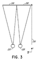
ここで図3を参照すると、「3次元」または「3−D」としての画像の知覚は、視認者の各眼への画像の若干異なる提示を提供することによって達成され得る。図3は、ユーザに関する3次元画像をシミュレートするための従来のディスプレイシステムを図示する。各眼210、220に対して1つの2つの明確に異なる画像190、200が、ユーザに出力される。画像190、200は、視認者の視線と平行な光学軸またはz−軸に沿って距離230だけ眼210、220から離間される。画像190、200は、平坦であって、眼210、220は、単一の遠近調節された状態をとることによって、画像上に合焦し得る。そのような3−Dディスプレイシステムは、ヒト視覚系に依拠し、画像190、200を組み合わせ、組み合わせられた画像の深度および/または尺度の知覚を提供する。
With reference to FIG. 3, the perception of the image as "three-dimensional" or "3-D" can be achieved by providing a slightly different presentation of the image to each eye of the viewer. FIG. 3 illustrates a conventional display system for simulating a three-dimensional image of a user. Two distinctly
しかしながら、ヒト視覚系は、より複雑であって、深度の現実的知覚を提供することは、より困難であることを理解されたい。例えば、従来の「3−D」ディスプレイシステムの多くの視認者は、そのようなシステムが不快であることを見出す、または深度の感覚を全く知覚しない場合がある。理論によって限定されるわけではないが、オブジェクトの視認者は、輻輳・開散運動(vergence)および遠近調節(accommodation)の組み合わせに起因して、オブジェクトを「3次元」として知覚し得ると考えられる。相互に対する2つの眼の輻輳・開散運動の移動(例えば、瞳孔が、眼の視線を収束させ、オブジェクトを凝視するための相互に向かって、またはそこから離れるように移動する、眼の転動)は、眼の水晶体および瞳孔の集束(または「遠近調節」)と密接に関連付けられる。通常条件下では、眼の水晶体の焦点を変化させること、または、眼を遠近調節し、1つのオブジェクトから異なる距離における別のオブジェクトに焦点を変化させることは、「遠近調節−輻輳・開散運動反射」および瞳孔拡張または収縮として知られる関係下、同一距離までの輻輳・開散運動における整合的変化を自動的に生じさせるであろう。同様に、輻輳・開散運動における変化は、正常条件下では、水晶体形状および瞳孔サイズの遠近調節における整合変化を誘起するであろう。本明細書に記載されるように、多くの立体視または「3−D」ディスプレイシステムは、3次元視点がヒト視覚系によって知覚されるように、各眼への若干異なる提示(したがって、若干異なる画像)を使用して、場面を表示する。しかしながら、そのようなシステムは、とりわけ、単に、場面の異なる提示を提供するが、眼が全画像情報を単一の遠近調節された状態において視認すると、「遠近調節−輻輳・開散運動反射」に対抗して機能するため、多くの視認者にとって不快である。遠近調節と輻輳・開散運動との間のより優れた整合を提供するディスプレイシステムは、3次元画像のより現実的かつ快適なシミュレーションを形成し得る。 However, it should be understood that the human visual system is more complex and it is more difficult to provide a realistic perception of depth. For example, many viewers of conventional "3-D" display systems may find such systems uncomfortable or may not perceive a sense of depth at all. Although not limited by theory, it is believed that a viewer of an object may perceive the object as "three-dimensional" due to a combination of convergence and accommodation. .. Movement of the convergence and divergence movements of the two eyes relative to each other (eg, eye rolling, in which the pupils move toward or away from each other to converge the line of sight of the eye and stare at an object. ) Is closely associated with the focusing (or "accommodation") of the crystalline lens and pupil of the eye. Under normal conditions, changing the focus of the crystalline lens of the eye, or adjusting the perspective of the eye and changing the focus from one object to another at different distances, is the "accommodation-convergence / divergence movement". Under the relationship known as "reflex" and pupil dilation or contraction, it will automatically produce consistent changes in convergence and divergence movements up to the same distance. Similarly, changes in convergence and divergence will induce matching changes in lens shape and pupil size accommodation under normal conditions. As described herein, many stereoscopic or "3-D" display systems present slightly different (and therefore slightly different) presentations to each eye so that the 3D viewpoint is perceived by the human visual system. Use image) to display the scene. However, such a system, among other things, simply provides a different presentation of the scene, but when the eye sees all the image information in a single accommodation, the "accommodation-convergence / divergence reflex". It is unpleasant for many viewers because it works against. A display system that provides better alignment between accommodation and convergence / divergence motion can form a more realistic and comfortable simulation of a 3D image.
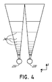
図4は、複数の深度平面を使用して3次元画像をシミュレートするためのアプローチの側面を図示する。図4を参照すると、z−軸上の眼210、220からの種々の距離におけるオブジェクトは、それらのオブジェクトが合焦するように、眼210、220によって遠近調節される。眼210、220は、特定の遠近調節された状態をとり、z−軸に沿って異なる距離においてオブジェクトに合焦する。その結果、特定の遠近調節された状態は、特定の深度平面におけるオブジェクトまたはオブジェクトの一部が、眼がその深度平面のための遠近調節された状態にあるとき合焦するように、関連付けられた焦点距離を有する、深度平面240のうちの特定の1つと関連付けられると言え得る。いくつかの実施形態では、3次元画像は、各眼210、220に対して画像の異なる提示を提供することによって、また、深度平面のそれぞれに対応する画像の異なる提示を提供することによってシミュレートされてもよい。例証を明確にするために、別個であるように示されるが、眼210、220の視野は、例えば、z−軸に沿った距離が増加するにつれて重複し得ることを理解されたい。加えて、例証を容易にするために、平坦として示されるが、深度平面の輪郭は、深度平面内の全ての特徴が特定の遠近調節された状態における眼と合焦するように、物理的空間内で湾曲され得ることを理解されたい。
FIG. 4 illustrates aspects of an approach for simulating a 3D image using multiple depth planes. Referring to FIG. 4, objects at various distances from the
オブジェクトと眼210または220との間の距離はまた、その眼によって視認されるようなそのオブジェクトからの光の発散の量を変化させ得る。図5A−5Cは、距離と光線の発散との間の関係を図示する。オブジェクトと眼210との間の距離は、減少距離R1、R2、およびR3の順序で表される。図5A−5Cに示されるように、光線は、オブジェクトまでの距離が減少するにつれてより発散する。距離が増加するにつれて、光線は、よりコリメートされる。換言すると、点(オブジェクトまたはオブジェクトの一部)によって生成される光場は、点がユーザの眼から離れている距離の関数である、球状波面曲率を有すると言え得る。曲率は、オブジェクトと眼210との間の距離の減少に伴って増加する。その結果、異なる深度平面では、光線の発散度もまた、異なり、発散度は、深度平面と視認者の眼210との間の距離の減少に伴って増加する。単眼210のみが、例証を明確にするために、図5A−5Cおよび本明細書の種々の他の図に図示されるが、眼210に関する議論は、視認者の両眼210および220に適用され得ることを理解されたい。
The distance between an object and the
理論によって限定されるわけではないが、ヒトの眼は、典型的には、有限数の深度平面を解釈し、深度知覚を提供することができると考えられる。その結果、知覚された深度の高度に真実味のあるシミュレーションが、眼にこれらの限定数の深度平面のそれぞれに対応する画像の異なる提示を提供することによって達成され得る。異なる提示は、視認者の眼によって別個に集束され、それによって、異なる深度平面上に位置する場面のための異なる画像特徴に合焦させるために要求される眼の遠近調節に基づいて、および/または焦点がずれている異なる深度平面上の異なる画像特徴の観察に基づいて、ユーザに深度合図を提供することに役立ててもよい。 Although not limited by theory, it is believed that the human eye can typically interpret a finite number of depth planes and provide depth perception. As a result, a highly authentic simulation of the perceived depth can be achieved by providing the eye with different presentations of images corresponding to each of these limited number of depth planes. Different presentations are focused separately by the eye of the viewer, thereby based on the accommodation of the eye required to focus on different image features for scenes located on different depth planes, and / Alternatively, it may help provide depth cues to the user based on observations of different image features on different out-of-focus depth planes.
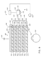
図6は、画像情報をユーザに出力するための導波管スタックの実施例を図示する。ディスプレイシステム250は、複数の導波管270、280、290、300、310を使用して3次元知覚を眼/脳に提供するために利用され得る、導波管のスタックまたはスタックされた導波管アセンブリ260を含む。いくつかの実施形態では、ディスプレイシステム250は、図2のシステム60であって、図6は、そのシステム60のいくつかの部分をより詳細に概略的に示す。例えば、導波管アセンブリ260は、図2のディスプレイ70の一部であってもよい。ディスプレイシステム250は、いくつかの実施形態では、ライトフィールドディスプレイと見なされてもよいことを理解されたい。加えて、導波管アセンブリ260はまた、接眼レンズとも称され得る。
FIG. 6 illustrates an example of a waveguide stack for outputting image information to a user. The
図6を継続して参照すると、導波管アセンブリ260はまた、複数の特徴320、330、340、350を導波管間に含んでもよい。いくつかの実施形態では、特徴320、330、340、350は、1つ以上のレンズであってもよい。導波管270、280、290、300、310および/または複数のレンズ320、330、340、350は、種々のレベルの波面曲率または光線発散を用いて画像情報を眼に送信するように構成されてもよい。各導波管レベルは、特定の深度平面と関連付けられてもよく、その深度平面に対応する画像情報を出力するように構成されてもよい。画像投入デバイス360、370、380、390、400は、導波管のための光源として機能してもよく、画像情報を導波管270、280、290、300、310の中に投入するために利用されてもよく、それぞれ、本明細書に説明されるように、眼210に向かって出力するために各個別の導波管を横断して入射光を分散させるように構成されてもよい。光は、画像投入デバイス360、370、380、390、400の出力表面410、420、430、440、450から出射し、導波管270、280、290、300、310の対応する入力表面460、470、480、490、500の中に投入される。いくつかの実施形態では、入力表面460、470、480、490、500はそれぞれ、対応する導波管の縁であってもよい、または対応する導波管の主要表面の一部(すなわち、世界510または視認者の眼210に直接面する導波管表面のうちの1つ)であってもよい。いくつかの実施形態では、光の単一ビーム(例えば、コリメートされたビーム)が、各導波管の中に投入され、クローン化されたコリメートビームの全体場を出力してもよく、これは、特定の導波管と関連付けられた深度平面に対応する特定の角度(および発散量)において眼210に向かって指向される。いくつかの実施形態では、画像投入デバイス360、370、380、390、400のうちの単一の1つは、複数(例えば、3つ)の導波管270、280、290、300、310と関連付けられ、その中に光を投入してもよい。
With reference to FIG. 6, the
いくつかの実施形態では、画像投入デバイス360、370、380、390、400はそれぞれ、それぞれ対応する導波管270、280、290、300、310の中への投入のために画像情報を生成する、離散ディスプレイである。いくつかの他の実施形態では、画像投入デバイス360、370、380、390、400は、例えば、画像情報を1つ以上の光学導管(光ファイバケーブル等)を介して画像投入デバイス360、370、380、390、400のそれぞれに送り得る、単一の多重化されたディスプレイの出力端である。画像投入デバイス360、370、380、390、400によって提供される画像情報は、異なる波長または色(例えば、本明細書に議論されるように、異なる原色)の光を含んでもよいことを理解されたい。
In some embodiments, the
いくつかの実施形態では、導波管270、280、290、300、310の中に投入される光は、光プロジェクタシステム520によって提供され、これは、光モジュール540を備え、これは、発光ダイオード(LED)等の光エミッタを含んでもよい。光モジュール540からの光は、ビームスプリッタ550を介して、光変調器530、例えば、空間光変調器によって指向および修正されてもよい。光変調器530は、導波管270、280、290、300、310の中に投入される光の知覚される強度を変化させるように構成されてもよい。空間光変調器の実施例は、液晶ディスプレイ(LCD)を含み、シリコン上液晶(LCOS)ディスプレイを含む。画像投入デバイス360、370、380、390、400は、概略的に図示され、いくつかの実施形態では、これらの画像投入デバイスは、光を導波管270、280、290、300、310の関連付けられたものの中に出力するように構成される、共通投影システム内の異なる光経路および場所を表し得ることを理解されたい。
In some embodiments, the light introduced into the
いくつかの実施形態では、ディスプレイシステム250は、光を種々のパターン(例えば、ラスタ走査、螺旋走査、リサジューパターン等)で1つ以上の導波管270、280、290、300、310の中に、最終的には、視認者の眼210に投影するように構成される、1つ以上の走査ファイバを備える、走査ファイバディスプレイであってもよい。いくつかの実施形態では、図示される画像投入デバイス360、370、380、390、400は、光を1つまたは複数の導波管270、280、290、300、310の中に投入するように構成される、単一走査ファイバまたは走査ファイバの束を概略的に表し得る。いくつかの他の実施形態では、図示される画像投入デバイス360、370、380、390、400は、複数の走査ファイバまたは走査ファイバの複数の束を概略的に表し得、それぞれ、光を導波管270、280、290、300、310のうちの関連付けられた1つの中に投入するように構成される。1つ以上の光ファイバは、光を光モジュール540から1つ以上の導波管270、280、290、300、310に透過するように構成されてもよいことを理解されたい。1つ以上の介在光学構造が、走査ファイバまたは複数のファイバと、1つ以上の導波管270、280、290、300、310との間に提供され、例えば、走査ファイバから出射する光を1つ以上の導波管270、280、290、300、310の中に再指向してもよいことを理解されたい。
In some embodiments, the
コントローラ560は、画像投入デバイス360、370、380、390、400、光源540、および光モジュール530の動作を含む、スタックされた導波管アセンブリ260のうちの1つ以上のものの動作を制御する。いくつかの実施形態では、コントローラ560は、ローカルデータ処理モジュール140の一部である。コントローラ560は、例えば、本明細書に開示される種々のスキームのいずれかに従って、導波管270、280、290、300、310への画像情報のタイミングおよびプロビジョニングを調整する、プログラミング(例えば、非一過性媒体内の命令)を含む。いくつかの実施形態では、コントローラは、単一の一体型デバイスまたは有線または無線通信チャネルによって接続される分散型システムであってもよい。コントローラ560は、いくつかの実施形態では、処理モジュール140または150(図2)の一部であってもよい。
The
図6を継続して参照すると、導波管270、280、290、300、310は、全内部反射(TIR)によって各個別の導波管内で光を伝搬するように構成されてもよい。導波管270、280、290、300、310はそれぞれ、主要上部表面および主要底部表面およびそれらの主要上部表面と主要底部表面との間に延在する縁を伴う、平面であるかまたは別の形状(例えば、湾曲)を有してもよい。図示される構成では、導波管270、280、290、300、310はそれぞれ、外部結合光学要素570、580、590、600、610を含んでもよく、これらの外部結合光学要素は、画像情報を眼210に出力するために、各個別の導波管内で伝搬する光を導波管から再指向させることによって、光を導波管から抽出するように構成される。抽出された光はまた、外部結合光と称され得、外部結合光学要素はまた、光抽出光学要素と称され得る。抽出された光のビームは、導波管によって、導波管内を伝搬する光が光抽出光学要素に衝打する場所において出力され得る。外部結合光学要素570、580、590、600、610は、例えば、本明細書にさらに議論されるような回折光学特徴を含む、格子であってもよい。説明の容易性および図面の明確性のために、導波管270、280、290、300、310の底部主要表面に配置されて図示されるが、いくつかの実施形態では、外部結合光学要素570、580、590、600、610は、本明細書にさらに議論されるように、上部主要表面および/または底部主要表面に配置されてもよい、および/または導波管270、280、290、300、310の体積内に直接配置されてもよい。いくつかの実施形態では、外部結合光学要素570、580、590、600、610は、透明基板に取り付けられ、導波管270、280、290、300、310を形成する、材料の層内に形成されてもよい。いくつかの他の実施形態では、導波管270、280、290、300、310は、材料のモノリシック部品であってもよく、外部結合光学要素570、580、590、600、610は、材料のその部品の表面上および/またはその内部に形成されてもよい。
With reference to FIG. 6, the
図6を継続して参照すると、本明細書に議論されるように、各導波管270、280、290、300、310は、光を出力し、特定の深度平面に対応する画像を形成するように構成される。例えば、眼の最近傍の導波管270は、眼210にコリメートされた光(そのような導波管270の中に投入された)を送達するように構成されてもよい。コリメートされた光は、光学無限遠焦点面を表し得る。次の上方の導波管280は、眼210に到達し得る前に、第1のレンズ350(例えば、負のレンズ)を通して通過する、コリメートされた光を送出するように構成されてもよい。そのような第1のレンズ350は、眼/脳が、その次の上方の導波管280から生じる光を光学無限遠から眼210に向かって内向きにより近い第1の焦点面から生じるように解釈するように、若干の凸面波面曲率を生成するように構成されてもよい。同様に、第3の上方の導波管290は、眼210に到達する前に、その出力光を第1のレンズ350および第2のレンズ340の両方を通して通過させる。第1のレンズ350および第2のレンズ340の組み合わせられた屈折力は、眼/脳が、第3の導波管290から生じる光が次の上方の導波管280からの光であったよりも光学無限遠から人物に向かって内向きにさらに近い第2の焦点面から生じるように解釈するように、別の漸増量の波面曲率を生成するように構成されてもよい。
With reference to FIG. 6, each
他の導波管層300、310およびレンズ330、320も同様に構成され、スタック内の最高導波管310は、人物に最も近い焦点面を表す集約焦点力のために、その出力をそれと眼との間のレンズの全てを通して送出する。スタックされた導波管アセンブリ260の他側の世界510から生じる光を視認/解釈するとき、レンズ320、330、340、350のスタックを補償するために、補償レンズ層620が、スタックの上部に配置され、下方のレンズスタック320、330、340、350の集約力を補償してもよい。そのような構成は、利用可能な導波管/レンズ対と同じ数の知覚される焦点面を提供する。導波管の外部結合光学要素およびレンズの集束側面は両方とも、静的であってもよい(すなわち、動的または電気活性ではない)。いくつかの代替実施形態では、一方または両方とも、電気活性特徴を使用して動的であってもよい。
The
いくつかの実施形態では、導波管270、280、290、300、310のうちの2つ以上のものは、同一の関連付けられた深度平面を有してもよい。例えば、複数の導波管270、280、290、300、310が、同一深度平面に設定される画像を出力するように構成されてもよい、または導波管270、280、290、300、310の複数のサブセットが、各深度平面に対して1つのセットを伴う、同一の複数の深度平面に設定される画像を出力するように構成されてもよい。これは、それらの深度平面において拡張された視野を提供するようにタイリングされた画像を形成する利点を提供し得る。
In some embodiments, two or more of the
図6を継続して参照すると、外部結合光学要素570、580、590、600、610は、導波管と関連付けられた特定の深度平面のために、光をその個別の導波管から再指向させることと、本光を適切な量の発散またはコリメーションを伴って出力することとの両方を行うように構成されてもよい。その結果、異なる関連付けられた深度平面を有する導波管は、外部結合光学要素570、580、590、600、610の異なる構成を有してもよく、これは、関連付けられた深度平面に応じて、異なる量の発散を伴う光を出力する。いくつかの実施形態では、光抽出光学要素570、580、590、600、610は、体積特徴または表面特徴であってもよく、これは、具体的角度において光を出力するように構成されてもよい。例えば、光抽出光学要素570、580、590、600、610は、体積ホログラム、表面ホログラム、および/または回折格子であってもよい。いくつかの実施形態では、特徴320、330、340、350は、レンズではなくてもよい。むしろ、それらは、単に、スペーサ(例えば、クラッディング層および/または空隙を形成するための構造)であってもよい。
Continuing with reference to FIG. 6, externally coupled
いくつかの実施形態では、外部結合光学要素570、580、590、600、610は、回折パターンまたは「回折光学要素」(また、本明細書では、「DOE」とも称される)を形成する、回折特徴である。好ましくは、DOEは、ビームの光の一部のみがDOEの各交差部で眼210に向かって偏向される一方、残りがTIRを介して導波管を通して移動し続けるように、十分に低い回折効率を有する。画像情報を搬送する光は、したがって、様々な場所において導波管から出射するいくつかの関連出射ビームに分割され、その結果は、導波管内でバウンスする本特定のコリメートされたビームに関して、眼210に向かって非常に均一なパターンで出射する放出となる。
In some embodiments, the
いくつかの実施形態では、1つ以上のDOEは、能動的に回折する「オン」状態と有意に回折しない「オフ」状態との間で切替可能であってもよい。例えば、切替可能なDOEは、ポリマー分散液晶の層を備えてもよく、その中で微小液滴は、ホスト媒体中に回折パターンを備え、微小液滴の屈折率は、ホスト材料の屈折率に実質的に整合するように切り替えられてもよい(その場合、パターンは、入射光を著しく回折させない)、または微小液滴は、ホスト媒体のものに整合しない屈折率に切り替えられてもよい(その場合、パターンは、入射光を能動的に回折させる)。 In some embodiments, the one or more DOEs may be switchable between an actively diffracting "on" state and a significantly less diffracting "off" state. For example, the switchable DOE may include a layer of polymer dispersed liquid crystal, in which the microdroplets have a diffraction pattern in the host medium, the index of refraction of the microdroplets being the index of refraction of the host material. It may be switched to be substantially consistent (in which case the pattern does not significantly diffract the incident light), or the microdroplets may be switched to a refractive index that is inconsistent with that of the host medium (its). If the pattern actively diffracts the incident light).
いくつかの実施形態では、カメラアセンブリ630(例えば、可視光および赤外線光カメラを含む、デジタルカメラ)が、眼210および/または眼210の周囲の組織の画像を捕捉し、例えば、ユーザ入力を検出する、および/またはユーザの生理学的状態を監視するために提供されてもよい。本明細書で使用されるように、カメラは、任意の画像捕捉デバイスであってもよい。いくつかの実施形態では、カメラアセンブリ630は、画像捕捉デバイスと、光(例えば、赤外線光)を眼に投影し、その光が、次いで、眼によって反射され、画像捕捉デバイスによって検出され得る、光源とを含んでもよい。いくつかの実施形態では、カメラアセンブリ630は、フレーム80(図2)に取り付けられてもよく、カメラアセンブリ630からの画像情報を処理し得る、処理モジュール140および/または150と電気通信してもよい。いくつかの実施形態では、1つのカメラアセンブリ630が、各眼に対して利用され、各眼を別個に監視してもよい。
In some embodiments, a camera assembly 630 (eg, a digital camera, including visible and infrared light cameras) captures an image of the
ここで図7を参照すると、導波管によって出力された出射ビームの実施例が、示される。1つの導波管が図示されるが、導波管アセンブリ260(図6)内の他の導波管も同様に機能し得、導波管アセンブリ260は、複数の導波管を含むことを理解されたい。光640が、導波管270の入力表面460において導波管270の中に投入され、TIRによって導波管270内を伝搬する。光640がDOE570上に衝突する点では、光の一部は、導波管から出射ビーム650として出射する。出射ビーム650は、略平行として図示されるが、本明細書に議論されるように、これらはまた、導波管270と関連付けられた深度平面に応じて、ある角度(例えば、発散出射ビームを形成する)において眼210に伝搬するように再指向されてもよい。略平行出射ビームは、眼210からの遠距離(例えば、光学無限遠)における深度平面に設定されるように現れる画像を形成するように光を外部結合する、外部結合光学要素を伴う導波管を示し得ることを理解されたい。他の導波管または他の外部結合光学要素のセットは、より発散する、出射ビームパターンを出力してもよく、これは、眼210がより近い距離に遠近調節し、それが網膜に合焦することを要求し、光学無限遠より眼210に近い距離からの光として脳によって解釈されるであろう。
Here, with reference to FIG. 7, an example of an emitted beam output by a waveguide is shown. Although one waveguide is shown, other waveguides within the waveguide assembly 260 (FIG. 6) may function as well, with the
いくつかの実施形態では、フルカラー画像が、原色、例えば、3つ以上の原色のそれぞれに画像をオーバーレイすることによって、各深度平面において形成されてもよい。図8は、スタックされた導波管アセンブリの実施例を図示し、各深度平面は、複数の異なる原色を使用して形成される画像を含む。図示される実施形態は、深度平面240a−240fを示すが、より多いまたはより少ない深度もまた、検討される。各深度平面は、第1の色Gの第1の画像、第2の色Rの第2の画像、および第3の色Bの第3の画像を含む、それと関連付けられた3つ以上の原色画像を有してもよい。異なる深度平面は、文字G、R、およびBに続くジオプタ(dpt)に関する異なる数字によって図に示される。単なる実施例として、これらの文字のそれぞれに続く数字は、ジオプタ(1/m)、すなわち、視認者からの深度平面の逆距離を示し、図中の各ボックスは、個々の原色画像を表す。いくつかの実施形態では、異なる波長の光の眼の集束における差異を考慮するために、異なる原色に関する深度平面の正確な場所は、変動してもよい。例えば、所与の深度平面に関する異なる原色画像は、ユーザからの異なる距離に対応する深度平面上に設置されてもよい。そのような配列は、視力およびユーザ快適性を増加させ得、および/または色収差を減少させ得る。 In some embodiments, a full-color image may be formed in each depth plane by overlaying the image on each of the primary colors, eg, three or more primary colors. FIG. 8 illustrates an example of a stacked waveguide assembly, where each depth plane contains an image formed using a plurality of different primary colors. The illustrated embodiments show depth planes 240a-240f, but more or less depth is also considered. Each depth plane contains three or more primary colors associated with it, including a first image of the first color G, a second image of the second color R, and a third image of the third color B. It may have an image. Different depth planes are illustrated by different numbers for diopters (dpt) following the letters G, R, and B. As a mere embodiment, the numbers following each of these letters indicate a diopter (1 / m), i.e., the inverse distance of the depth plane from the viewer, and each box in the figure represents an individual primary color image. In some embodiments, the exact location of the depth plane for different primary colors may vary to account for differences in eye focusing of light of different wavelengths. For example, different primary color images for a given depth plane may be placed on the depth plane corresponding to different distances from the user. Such an arrangement can increase visual acuity and user comfort and / or reduce chromatic aberration.
いくつかの実施形態では、各原色の光は、単一の専用導波管によって出力されてもよく、その結果、各深度平面は、それと関連付けられた複数の導波管を有してもよい。そのような実施形態では、文字G、R、またはBを含む、図中の各ボックスは、個々の導波管を表すものと理解され得、3つの導波管は、深度平面毎に提供されてもよく、3つの原色画像が、深度平面毎に提供される。各深度平面と関連付けられた導波管は、本図面では、説明を容易にするために相互に隣接して示されるが、物理的デバイスでは、導波管は全て、レベル毎に1つの導波管を伴うスタックで配列されてもよいことを理解されたい。いくつかの他の実施形態では、複数の原色が、例えば、単一の導波管のみが深度平面毎に提供され得るように、同一の導波管によって出力されてもよい。 In some embodiments, the light of each primary color may be output by a single dedicated waveguide, so that each depth plane may have multiple waveguides associated with it. .. In such an embodiment, each box in the figure, including the letter G, R, or B, can be understood to represent an individual waveguide, and three waveguides are provided for each depth plane. Three primary color images may be provided for each depth plane. The waveguides associated with each depth plane are shown adjacent to each other in this drawing for ease of explanation, but in physical devices, all waveguides are one waveguide per level. It should be understood that they may be arranged in a stack with tubes. In some other embodiments, multiple primary colors may be output by the same waveguide, eg, so that only a single waveguide can be provided for each depth plane.
図8を継続して参照すると、いくつかの実施形態では、Gは、緑色であって、Rは、赤色であって、Bは、青色である。いくつかの他の実施形態では、マゼンタ色およびシアン色を含む、光の他の波長と関連付けられた他の色も、赤色、緑色、または青色のうちの1つ以上のものに加えて使用されてもよい、またはそれらに取って代わってもよい。 Continuing with reference to FIG. 8, in some embodiments, G is green, R is red, and B is blue. In some other embodiments, other colors associated with other wavelengths of light, including magenta and cyan, are also used in addition to one or more of red, green, or blue. It may or may replace them.
本開示全体を通した所与の光の色の言及は、その所与の色として視認者によって知覚される、光の波長の範囲内の1つ以上の波長の光を包含するものと理解されると理解されたい。例えば、赤色光は、約620〜780nmの範囲内である1つ以上の波長の光を含んでもよく、緑色光は、約492〜577nmの範囲内である1つ以上の波長の光を含んでもよく、青色光は、約435〜493nmの範囲内である1つ以上の波長の光を含んでもよい。 References to a given light color throughout the present disclosure are understood to include light of one or more wavelengths within the wavelength range of light perceived by the viewer as that given color. Please understand. For example, red light may contain light of one or more wavelengths in the range of about 620-780 nm, and green light may contain light of one or more wavelengths in the range of about 492-577 nm. Often, the blue light may include light of one or more wavelengths in the range of about 435-493 nm.
いくつかの実施形態では、光源540(図6)は、視認者の視覚的知覚範囲外の1つ以上の波長、例えば、赤外線および/または紫外線波長の光を放出するように構成されてもよい。加えて、ディスプレイ250の導波管の内部結合、外部結合、および他の光再指向構造は、例えば、イメージング用途および/またはユーザ刺激用途のために、本光をディスプレイからユーザの眼210に向かって指向および放出するように構成されてもよい。
In some embodiments, the light source 540 (FIG. 6) may be configured to emit light of one or more wavelengths outside the visual perception range of the viewer, such as infrared and / or ultraviolet wavelengths. .. In addition, the internal coupling, outer coupling, and other optical redirection structures of the waveguide of the
ここで図9Aを参照すると、いくつかの実施形態では、導波管に衝突する光は、その光を導波管の中に内部結合するために再指向される必要があり得る。内部結合光学要素が、光をその対応する導波管の中に再指向および内部結合するために使用されてもよい。図9Aは、各々が内部結合光学要素を含む複数またはセットのスタックされた導波管660の実施例の断面側面図を図示する。導波管はそれぞれ、1つ以上の異なる波長または1つ以上の異なる波長範囲の光を出力するように構成されてもよい。スタック660は、スタック260(図6)に対応してもよく、スタック660の図示される導波管は、複数の導波管270、280、290、300、310の一部に対応してもよいが、画像投入デバイス360、370、380、390、400のうちの1つ以上のものからの光が、内部結合のために光が再指向されることを要求する位置から、導波管の中に投入されることを理解されたい。
Now referring to FIG. 9A, in some embodiments, the light colliding with the waveguide may need to be redirected in order to internally couple the light into the waveguide. Internally coupled optics may be used to redirect and internally couple the light into its corresponding waveguide. FIG. 9A illustrates a cross-sectional side view of an embodiment of a plurality or set of stacked
スタックされた導波管の図示されるセット660は、導波管670、680、および690を含む。各導波管は、関連付けられた内部結合光学要素(導波管上の光入力面積とも称され得る)を含み、例えば、内部結合光学要素700は、導波管670の主要表面(例えば、上側主要表面)上に配置され、内部結合光学要素710は、導波管680の主要表面(例えば、上側主要表面)上に配置され、内部結合光学要素720は、導波管690の主要表面(例えば、上側主要表面)上に配置される。いくつかの実施形態では、内部結合光学要素700、710、720のうちの1つ以上のものは、個別の導波管670、680、690の底部主要表面上に配置されてもよい(特に、1つ以上の内部結合光学要素は、反射性偏向光学要素である)。図示されるように、内部結合光学要素700、710、720は、その個別の導波管670、680、690の上側主要表面(または次の下側導波管の上部)上に配置されてもよく、特に、それらの内部結合光学要素は、透過性偏向光学要素である。いくつかの実施形態では、内部結合光学要素700、710、720は、個別の導波管670、680、690の本体内に配置されてもよい。いくつかの実施形態では、本明細書に議論されるように、内部結合光学要素700、710、720は、他の光の波長を透過させながら、光の1つ以上の波長を選択的に再指向させるように波長選択的である。その個別の導波管670、680、690の片側または角に図示されるが、内部結合光学要素700、710、720は、いくつかの実施形態では、その個別の導波管670、680、690の他の面積内に配置されてもよいことを理解されたい。
The illustrated set 660 of stacked waveguides includes
図示されるように、内部結合光学要素700、710、720は、相互から側方にオフセットされてもよい。いくつかの実施形態では、各内部結合光学要素は、それが光を受信し、その光が別の内部結合光学要素を通して通過しないように、オフセットされてもよい。例えば、各内部結合光学要素700、710、720は、図6に示されるように、光を異なる画像投入デバイス360、370、380、390、および400から受信するように構成されてもよく、光を内部結合光学要素700、710、720の他のものから実質的に受信しないように、他の内部結合光学要素700、710、720から分離されてもよい(例えば、側方に離間される)。
As shown, the internally coupled
各導波管はまた、関連付けられた光分散要素を含み、例えば、光分散要素730は、導波管670の主要表面(例えば、上部主要表面)上に配置され、光分散要素740は、導波管680の主要表面(例えば、上部主要表面)上に配置され、光分散要素750は、導波管690の主要表面(例えば、上部主要表面)上に配置される。いくつかの他の実施形態では、光分散要素730、740、750は、それぞれ、関連付けられた導波管670、680、690の底部主要表面上に配置されてもよい。いくつかの他の実施形態では、光分散要素730、740、750は、それぞれ、関連付けられた導波管670、680、690の上部および底部両方の主要表面上に配置されてもよい、または光分散要素730、740、750は、それぞれ、異なる関連付けられた導波管670、680、690内の上部主要表面および底部主要表面の異なるもの上に配置されてもよい。
Each waveguide also contains an associated light dispersion element, eg, the
導波管670、680、690は、例えば、材料のガス、液体および/または固体層によって離間および分離されてもよい。例えば、図示されるように、層760aは、導波管670および680を分離してもよく、層760bは、導波管680および690を分離してもよい。いくつかの実施形態では、層760aおよび760bは、低屈折率材料(すなわち、導波管670、680、690の直近のものを形成する材料より低い屈折率を有する材料)から形成される。好ましくは、層760a、760bを形成する材料の屈折率は、導波管670、680、690を形成する材料の屈折率の0.05以上または0.10以下である。有利には、より低い屈折率の層760a、760bは、導波管670、680、690を通る光の全内部反射(TIR)(例えば、各導波管の上部主要表面および底部主要表面間のTIR)を促進する、クラッディング層として機能してもよい。いくつかの実施形態では、層760a、760bは、空気から形成される。図示されないが、導波管の図示されるセット660の上部および底部は、直近クラッディング層を含んでもよいことを理解されたい。
The
好ましくは、製造および他の考慮点を容易にするために、導波管670、680、690を形成する材料は、類似または同一であって、層760a、760bを形成する材料は、類似または同一である。いくつかの実施形態では、導波管670、680、690を形成する材料は、1つ以上の導波管間で異なってもよい、および/または、層760a、760bを形成する材料は、依然として、前述の種々の屈折率関係を保持しながら、異なってもよい。
Preferably, for ease of manufacture and other considerations, the materials forming the
図9Aを継続して参照すると、光線770、780、790が、導波管のセット660に入射する。光線770、780、790は、1つ以上の画像投入デバイス360、370、380、390、400(図6)によって導波管670、680、690の中に投入されてもよいことを理解されたい。
Continuing with reference to FIG. 9A, rays 770, 780, 790 enter the
いくつかの実施形態では、光線770、780、790は、異なる色に対応し得る、異なる性質、例えば、異なる波長または異なる波長範囲を有する。内部結合光学要素700、710、720はそれぞれ、光が、TIRによって、導波管670、680、690のうちの個別の1つを通して伝搬するように、入射光を偏向させる。いくつかの実施形態では、内部結合光学要素700、710、720はそれぞれ、他の波長を下層導波管および関連付けられた内部結合光学要素に透過させながら、1つ以上の特定の光の波長を選択的に偏向させる。
In some embodiments, the
例えば、内部結合光学要素700は、それぞれ、異なる第2および第3の波長または波長範囲を有する、光線780および790を透過させながら、第1の波長または波長範囲を有する光線770を偏向させるように構成されてもよい。透過された光線780は、第2の波長または波長範囲の光を偏向させるように構成される、内部結合光学要素710に衝突し、それによって偏向される。光線790は、第3の波長または波長範囲の光を選択的に偏向させるように構成される、内部結合光学要素720によって偏向される。
For example, the internally coupled
図9Aを継続して参照すると、偏向された光線770、780、790は、対応する導波管670、680、690を通して伝搬するように偏向される。すなわち、各導波管の内部結合光学要素700、710、720は、光をその対応する導波管670、680、690の中に偏向させ、光を対応する導波管の中に内部結合する。光線770、780、790は、光をTIRによって個別の導波管670、680、690を通して伝搬させる角度で偏向される。光線770、780、790は、導波管の対応する光分散要素730、740、750に衝突するまで、TIRによって個別の導波管670、680、690を通して伝搬する。
Continuing with reference to FIG. 9A, the deflected
ここで図9Bを参照すると、図9Aの複数のスタックされた導波管の実施例の斜視図が、図示される。前述のように、内部結合された光線770、780、790は、それぞれ、内部結合光学要素700、710、720によって偏向され、次いで、それぞれ、導波管670、680、690内でTIRによって伝搬する。光線770、780、790は、次いで、それぞれ、光分散要素730、740、750に衝突する。光分散要素730、740、750は、それぞれ、外部結合光学要素800、810、820に向かって伝搬するように、光線770、780、790を偏向させる。
Here, with reference to FIG. 9B, a perspective view of an embodiment of the plurality of stacked waveguides of FIG. 9A is illustrated. As mentioned above, the internally coupled
いくつかの実施形態では、光分散要素730、740、750は、直交瞳エクスパンダ(OPE)である。いくつかの実施形態では、OPEは、光を外部結合光学要素800、810、820に偏向または分散させ、いくつかの実施形態では、また、外部結合光学要素に伝搬するにつれて、本光のビームまたはスポットサイズを増加させ得る。いくつかの実施形態では、光分散要素730、740、750は、省略されてもよく、内部結合光学要素700、710、720は、光を外部結合光学要素800、810、820に直接偏向させるように構成されてもよい。例えば、図9Aを参照すると、光分散要素730、740、750は、それぞれ、外部結合光学要素800、810、820と置換されてもよい。いくつかの実施形態では、外部結合光学要素800、810、820は、光を視認者の眼210(図7)に指向させる、射出瞳(EP)または射出瞳エクスパンダ(EPE)である。OPEは、少なくとも1つの軸においてアイボックスの寸法を増加させるように構成されてもよく、EPEは、OPEの軸と交差する、例えば、直交する軸においてアイボックスを増加させてもよいことを理解されたい。例えば、各OPEは、光の残りの部分が導波管を辿って伝搬し続けることを可能にしながら、OPEに衝打する光の一部を同一導波管のEPEに再指向するように構成されてもよい。OPEへの衝突に応じて、再び、残りの光の別の部分は、EPEに再指向され、その部分の残りの部分は、導波管等を辿ってさらに伝搬し続ける。同様に、EPEへの衝打に応じて、衝突光の一部は、導波管からユーザに向かって指向され、その光の残りの部分は、EPに再び衝打するまで、導波管を通して伝搬し続け、その時点で、衝突する光の別の部分は、導波管から指向される等となる。その結果、内部結合された光の単一ビームは、その光の一部がOPEまたはEPEによって再指向される度に、「複製」され、それによって、図6に示されるように、クローン化された光のビーム野を形成し得る。いくつかの実施形態では、OPEおよび/またはEPEは、光のビームのサイズを修正するように構成されてもよい。
In some embodiments, the
故に、図9Aおよび9Bを参照すると、いくつかの実施形態では、導波管のセット660は、各原色に対し、導波管670、680、690と、内部結合光学要素700、710、720と、光分散要素(例えば、OPE)730、740、750と、外部結合光学要素(例えば、EP)800、810、820とを含む。導波管670、680、690は、各1つの間に空隙/クラッディング層を伴ってスタックされてもよい。内部結合光学要素700、710、720は、(異なる波長の光を受信する異なる内部結合光学要素を用いて)入射光をその導波管の中に再指向または偏向させる。光は、次いで、個別の導波管670、680、690内にTIRをもたらすであろう角度で伝搬する。示される実施例では、光線770(例えば、青色光)は、前述の様式において、第1の内部結合光学要素700によって偏光され、次いで、導波管を辿ってバウンスし続け、光分散要素(例えば、OPE)730、次いで、外部結合光学要素(例えば、EP)800と相互作用する。光線780および790(例えば、それぞれ、緑色光および赤色光)は、導波管670を通して通過し、光線780は、内部結合光学要素710上に入射し、それによって偏向される。光線780は、次いで、TIRを介して、導波管680を辿ってバウンスし、その光分散要素(例えば、OPE)740、次いで、外部結合光学要素(例えば、EP)810に進むであろう。最後に、光線790(例えば、赤色光)は、導波管690を通して通過し、導波管690の光内部結合光学要素720に衝突する。光内部結合光学要素720は、光線が、TIRによって光分散要素(例えば、OPE)750に伝搬し、次いで、TIRによって外部結合光学要素(例えば、EP)820に伝搬するように、光線790を偏向させる。外部結合光学要素820は、次いで、最後に、光線790を視認者に外部結合し、視認者はまた、他の導波管670、680からの外部結合した光も受信する。
Therefore, with reference to FIGS. 9A and 9B, in some embodiments, the waveguide set 660 has the
図9Cは、図9Aおよび9Bの複数のスタックされた導波管の実施例の上下平面図を図示する。図示されるように、導波管670、680、690は、各導波管の関連付けられた光分散要素730、740、750および関連付けられた外部結合光学要素800、810、820とともに、垂直に整合されてもよい。しかしながら、本明細書に議論されるように、内部結合光学要素700、710、720は、垂直に整合されない。むしろ、内部結合光学要素は、好ましくは、非重複する(例えば、上下図に見られるように、側方に離間される)。本明細書でさらに議論されるように、本非重複空間配列は、1対1ベースで異なるリソースから異なる導波管の中への光の投入を促進し、それによって、具体的光源が具体的導波管に一意に結合されることを可能にする。いくつかの実施形態では、非重複の空間的に分離される内部結合光学要素を含む配列は、偏移瞳システムと称され得、これらの配列内の内部結合光学要素は、サブ瞳に対応し得る。
FIG. 9C illustrates a top-down plan view of an embodiment of the plurality of stacked waveguides of FIGS. 9A and 9B. As shown, the
ここで、図10Aおよび10Bを参照する。上記に説明されるもの等の拡張現実ディスプレイのいくつかの実施形態は、拡張現実システム内に含まれる可変焦点レンズ要素の焦点距離を調整することによって、光の波面を調節するように構成されてもよい(拡張現実システムから投影される画像情報のための光および周囲実世界内のオブジェクトからの入射光を含む)。上記に議論されるように、拡張現実システムは、光をユーザまたは視認者(例えば、図2の視認者またはユーザ90)の眼に向かって投影する、複数のスタックされた導波管(例えば、図9Aおよび9Bの複数またはセットのスタックされた導波管660に対応する、または図6のスタックされた導波管アセンブリ260に対応する)を含み得る、ディスプレイデバイスを備えてもよい。いくつかの他の実施形態では、ディスプレイデバイスは、単一導波管のみを含んでもよい。その結果、複数の導波管が、本明細書の開示の種々の部分で参照されるが、複数の導波管は、単一導波管によって置換されてもよいことを理解されたい。
Here, reference is made to FIGS. 10A and 10B. Some embodiments of augmented reality displays, such as those described above, are configured to adjust the wave front of light by adjusting the focal length of the varifocal lens elements contained within the augmented reality system. It may (including light for image information projected from an augmented reality system and incident light from objects in the surrounding real world). As discussed above, augmented reality systems project light into the eyes of a user or viewer (eg, the viewer or
本明細書に議論されるように、導波管から投影された光は、仮想拡張現実画像情報を視認者に提供するために使用されてもよい。光は、ユーザが、視認者からの1つ以上の異なる深度または距離から生じるように光を知覚するように投影されてもよい。ディスプレイデバイスは、ユーザにディスプレイデバイスを通して周囲環境内の実世界オブジェクトが見えるように、光学的に透過性であってもよい。いくつかの実施形態では、導波管は、固定屈折力を有するように構成されてもよい。投影された光が異なる深度から生じるような外観を提供するために、導波管は、異なる深度平面に対応する異なる発散量を伴う光の発散ビームを出力するように構成されてもよい。 As discussed herein, the light projected from the waveguide may be used to provide virtual augmented reality image information to the viewer. The light may be projected so that the user perceives the light as coming from one or more different depths or distances from the viewer. The display device may be optically transparent so that the user can see real-world objects in the surrounding environment through the display device. In some embodiments, the waveguide may be configured to have a fixed refractive power. To provide the appearance that the projected light comes from different depths, the waveguide may be configured to output a divergent beam of light with different divergence amounts corresponding to different depth planes.
導波管の固定屈折力は、視認者の眼が、好適な遠近調節範囲を有し、導波管によって出力された光を集束させると想定していることを理解されたい。しかしながら、前述のように、一部の視認者は、明確に見えるように補正レンズを要求し得、その結果、導波管から出力された画像情報は、そのような視認者に明確に見えない場合がある。いくつかの実施形態では、第1の可変焦点レンズ要素が、導波管と視認者の眼との間に提供され、導波管によって出力された光の波面に対して適切な調節を提供し、本光が視認者の眼によって正しく集束されることを可能にしてもよい。しかしながら、本第1のレンズ要素もまた、周囲環境から視認者の眼に伝搬する光の経路内にある。その結果、第1のレンズ要素は、周囲環境からの光の波面を修正し、それによって、収差を世界の視認者のビューに生じさせ得る。そのような収差を補正するために、第2の可変焦点レンズ要素が、第1の可変焦点レンズ要素とは複数のスタックされた導波管の反対側に配置されてもよい。すなわち、第2の可変焦点レンズ要素は、複数のスタックされた導波管と周囲実世界との間にあって、周囲環境内の実世界オブジェクトからの光の波面を調節してもよい。第2の可変焦点レンズ要素は、第1の可変焦点レンズ要素によって生じる収差を補償するように構成されてもよい。いくつかの実施形態では、第2の可変焦点レンズもまた、導波管によって生じる収差を補償するように構成されてもよい。 It should be understood that the fixed refractive power of the waveguide assumes that the visual eye has a suitable accommodation range and focuses the light output by the waveguide. However, as mentioned above, some viewers may require a correction lens to be clearly visible, and as a result, the image information output from the waveguide is not clearly visible to such viewers. In some cases. In some embodiments, a first varifocal lens element is provided between the waveguide and the eye of the viewer to provide proper adjustment to the wave front of the light output by the waveguide. , It may be possible to allow the main light to be properly focused by the eyes of the viewer. However, the first lens element is also in the path of light propagating from the ambient environment to the viewer's eye. As a result, the first lens element modifies the wave front of light from the ambient environment, thereby causing aberrations in the viewer's view of the world. In order to correct such aberration, the second varifocal lens element may be arranged on the opposite side of the plurality of stacked waveguides from the first varifocal lens element. That is, the second varifocal lens element may be located between the plurality of stacked waveguides and the surrounding real world to adjust the wave plane of light from real world objects in the surrounding environment. The second varifocal lens element may be configured to compensate for the aberrations caused by the first varifocal lens element. In some embodiments, the second varifocal lens may also be configured to compensate for the aberrations caused by the waveguide.
いくつかの実施形態では、第2の可変焦点レンズ要素の焦点は、第1の可変焦点レンズ要素の焦点の反転または反対であってもよい。例えば、第1の可変焦点レンズ要素が、正の屈折力を有する場合、第2の可変焦点レンズ要素は、負の屈折力を有してもよく、これは、類似した大きさであってもよい。いくつかの他の実施形態では、第1の可変焦点レンズ要素の屈折力および介在導波管の屈折力の両方を補償するために、第2のレンズ要素の屈折力は、第1のレンズ要素および導波管の集約屈折力と反対かつ類似した大きさであってもよい。 In some embodiments, the focus of the second varifocal lens element may be the reversal or opposite of the focus of the first varifocal lens element. For example, if the first varifocal lens element has a positive power, the second varifocal lens element may have a negative power, even if they are of similar magnitude. good. In some other embodiments, the refractive power of the second lens element is the first lens element to compensate for both the refractive power of the first varifocal lens element and the refractive power of the intervening waveguide. And the magnitude may be opposite to and similar to the intensive refractive power of the waveguide.
いくつかの他の実施形態では、導波管は、屈折力を有していなくてもよく(例えば、導波管は、コリメートされた光を出力するように構成されてもよく)、第1の可変焦点レンズ要素は、導波管から放出される光の波面を修正し、画像情報が特定の深度平面上にあるように視認者によって解釈されるために適切な発散量を提供するように構成されてもよい。適切な発散量は、画像情報を特定の深度平面上に設置するための屈折力が、その深度平面のための視認者の光学処方箋を考慮するために特定の差異によって調節され得るので、異なる視認者のために変動し得ることを理解されたい。そのような実施形態では、第1および第2の可変焦点レンズ要素間の導波管スタックは、単に、単一導波管によって形成されてもよい。 In some other embodiments, the waveguide may not have refractive power (eg, the waveguide may be configured to output collimated light), first. The varifocal lens element of the It may be configured. Appropriate divergence is different because the refractive power for placing the image information on a particular depth plane can be adjusted by a particular difference to take into account the viewer's optical prescription for that depth plane. Please understand that it can fluctuate for the sake of others. In such an embodiment, the waveguide stack between the first and second varifocal lens elements may simply be formed by a single waveguide.
第1および第2の可変焦点レンズ要素は、視認者の眼のうちの一方のために提供されてもよく、第1および第2の可変焦点レンズ要素に類似する、第3および第4の可変焦点レンズ要素が、それぞれ、視認者の他方の眼のために提供されてもよいことを理解されたい。 The first and second varifocal lens elements may be provided for one of the viewer's eyes, and the third and fourth varifocal lenses are similar to the first and second varifocal lens elements. It should be understood that each focal lens element may be provided for the other eye of the viewer.
図10Aおよび10Bは、可変焦点レンズ要素と、導波管スタックとを有する、ディスプレイシステム(例えば、拡張現実ディスプレイシステム)の実施例の略図を示す。ディスプレイシステム2010は、ディスプレイシステム250(図6)に対応してもよいことを理解されたい。図10Aの例示的ディスプレイシステム2010は、単一導波管を伴う導波管スタックを示す一方、図10Bの実施例は、複数の導波管を伴う導波管スタックを示す。図10Aおよび10Bの両方では、第1の可変焦点レンズ要素2007aおよび第2の可変焦点レンズ要素2007bは、導波管スタック2005(図10A)の両側に配置され、第3の可変焦点レンズ要素2008aおよび第4の可変焦点レンズ要素2008bは、導波管スタック2006(図10B)の両側に配置される。
10A and 10B show a schematic representation of an embodiment of a display system (eg, an augmented reality display system) having a varifocal lens element and a waveguide stack. It should be understood that the
図10Aおよび10Bの種々の図示される導波管2005a、2005b、2006a、2006bは、図6の導波管270、280、290、300、310および/または図9Aおよび9Bの導波管670、680、および690の個々のものに類似する特性および/または特徴を有してもよい。導波管スタック2005、2006は、図9Aおよび9Bの複数またはセットのスタックされた導波管660または図6のスタックされた導波管アセンブリ260に類似する特性および/または特徴を有してもよい。いくつかの実施形態では、導波管2005a、2005b、2006a、2006bは、屈折力、例えば、固定屈折力を伴う導波管を提供する、回折光学要素等の光学要素を含んでもよい。例えば、これらの導波管のうちの1つ以上のものは、0ジオプタ〜約5.0ジオプタ、約0.5ジオプタ〜約4.5ジオプタ、約1.0ジオプタ〜約4.0ジオプタ、約1.5ジオプタ〜約3.5ジオプタ、約2.0ジオプタ〜約3.0ジオプタの範囲内、またはこれらの範囲またはサブ範囲内の任意の値の屈折力を有してもよい。別の実施例として、特定の実施形態では、導波管はそれぞれ、1.5ジオプタの屈折力を有してもよい。
The various
前述のように、光学源2003または2004から画像情報(例えば、仮想コンテンツ)を提供する光は、光が全内部反射によってそれらの導波管のそれぞれを通して伝搬するように、それぞれ、導波管2005aまたは2006aの中に投入されてもよい。伝搬する光は、導波管2005a(または導波管2005b)から外部結合要素(例えば、図9Aおよび9Bの外部結合要素800、810、820に対応する)によってユーザの眼2001に向かって投影されてもよい。いくつかの実施形態では、光学源2003、2004は、本明細書に開示されるように、可動ファイバを利用して、2D画像パターンを作成する、ファイバ走査デバイス(FSD)であってもよい。FSDは、例えば、ラスタ走査、スパイラル走査、リサジュー等の種々のパターンにおいて光を投影させることによって、2D画像パターンを作成してもよい。いくつかの他の実施形態では、光学源2003a(および/または2003b)は、例えば、同様に本明細書に開示されるように、全画像が導波管上に投影される、画像投影システムであってもよい。光学源2003a(および/または2003b)からの光は、導波管の縁を通して、または導波管の主要表面を通して、導波管スタック2005の中に投入されてもよいことを理解されたい。導波管スタックは、複数の導波管を含む場合、光学源2003および/または2004は、光をこれらの導波管の複数のものの中に投入するように構成されてもよい、または付加的な光学源、例えば、各導波管に対して1つの光学源が、提供されてもよい。
As mentioned above, the light that provides the image information (eg, virtual content) from the
図10Aおよび10Bに図示されるように、第1の可変焦点レンズ要素2007aが、導波管スタック2005とユーザの眼2001との間に配置されてもよく、第2の可変焦点レンズ要素2007bが、導波管スタック2005とユーザを囲繞する実世界との間に配置されてもよい。眼2001は、図6の視認者の眼210に対応してもよいことを理解されたい。同様に、第3の可変焦点レンズ要素2008aが、導波管スタック2006とユーザの眼2002との間に配置されてもよく、第2の可変焦点レンズ要素2008bが、導波管スタック2006とユーザを囲繞する実世界との間に配置されてもよい。
As illustrated in FIGS. 10A and 10B, a first
いくつかの実施形態では、第1および第2の可変焦点レンズ要素2007aおよび2007bおよび第3および第4の可変焦点レンズ要素2008aおよび2008bは、適合可能光学要素であってもよい。適合可能光学要素は、例えば、電気信号をそこに印加し、その上に入射する波面の形状を変化させることによって、動的に改変されてもよい。いくつかの実施形態では、適合可能光学要素は、動的レンズ(例えば、液晶レンズ、電気活性レンズ、可動要素を伴う従来の屈折レンズ、機械的変形ベースのレンズ、エレクトロウェッティングレンズ、エラストマレンズ、または異なる屈折率を伴う複数の流体)等の透過光学要素を備えてもよい。適合可能光学形状、屈折率、または他の特性を改変することによって、その上に入射する波面が、本明細書に説明されるように、変化され、例えば、視認者の眼による光の焦点を改変し得る。
In some embodiments, the first and second
いくつかの実施形態では、可変焦点レンズ要素2007a、2007b、2008a、2008bは、2つの基板間に挟入される液晶の層を備えてもよい。基板は、例えば、ガラス、プラスチック、アクリル等の光学的に透過性の材料を備えてもよい。いくつかの実施形態では、基板は、平坦であってもよい。いくつかの実施形態では、基板は、基板の一部が固定屈折力を有し得るように、湾曲領域を有してもよい。
In some embodiments, the
いくつかの実施形態では、可変焦点レンズ要素2007a、2007b、2008a、2008bの屈折力は、例えば、液晶層および/または基板と統合される1つ以上の薄膜トランジスタ(TFT)および/または電極を介して液晶層に印加される電気信号(例えば、電流および/または電圧)を調節することによって、変動されてもよい。液晶層内の液晶種の配向は、層の屈折率を決定することを理解されたい。印加された電気信号は、液晶種の配向を設定し、それによって、印加される電気信号を改変することによって、所望に応じて、液晶層の屈折率が変動されることを可能にする。いくつかの実施形態では、可変焦点レンズ要素2007a、2007b、2008a、2008bの屈折力は、約±5.0ジオプタ間で変動されてもよい(例えば、約−4.0ジオプタ〜+4.0ジオプタ、約−3.5ジオプタ〜約+3.5ジオプタ、約−3.0ジオプタ〜約+3.0ジオプタ、約−2.0ジオプタ〜約+2.0ジオプタ、約−1.5ジオプタ〜約+1.5ジオプタ、これらの範囲またはサブ範囲のいずれか内の値を含む)。
In some embodiments, the refractive power of the
有利には、可変焦点レンズ要素2007a、2007b、2008a、2008bは、その個別の関連付けられた導波管スタック2005、2006の導波管の開口に実質的に合致される広開口を有してもよい。いくつかの実施形態では、可変焦点レンズ要素2007a、2007b、2008a、2008bの開口は、導波管スタック2005、2006の導波管の表面積と実質的に等しくてもよい(例えば、約±20%、約±15%、または約±10%以内)。その結果、可変焦点レンズ要素2007a、2007b、2008a、2008bおよび導波管スタック2005、2206が、光を関連付けられた眼2001、2002に透過させる面積は、実質的に等しくあり得る。
Advantageously, the
図10Aおよび10Bを継続して参照すると、第1および第3の可変焦点レンズ要素2007a、2008aはそれぞれ、その屈折力を変動させ、それぞれ、導波管スタック2005、2006の導波管から投影された光の波面を調節し、その光を、それぞれ、眼2001、2002の網膜上に適切に集束させ得る。本明細書に記載されるように、第1および第3の可変焦点レンズ要素2007a、2008aは、収差を周囲環境内のオブジェクト2009からの入射光の波面に生じさせ、それによって、第1の可変焦点レンズ要素2007aを通して視認される実世界オブジェクト2009の光学画質を減少させ得る。第2および第4の可変焦点レンズ要素2007b、2008bは、有利には、オブジェクト2009を視認するとき、それぞれ、第1および第3の可変焦点レンズ要素2007a、2008aおよび任意の導波管によって導入される収差を補償し得る。いくつかの実施形態では、第2および第4の可変焦点レンズ要素2007b、2008bは、それぞれ、第1および第3の可変焦点レンズ要素2007a、2008aおよび関連付けられた導波管スタック2005、2006によって提供される屈折力と反対の屈折力を提供するように構成されてもよい。いくつかの実施形態では、反対の屈折力の大きさは、各眼2001、2002に対するディスプレイシステム2010の正味屈折力が、眼が輻輳・開散運動している深度平面における眼のための光学処方箋と等しくなるように構成されるようなものである。第1および第2の可変焦点レンズ要素2007aおよび2007bによって提供される屈折力は、電子ハードウェア制御システム2011によって変動および制御されてもよい。いくつかの実施形態では、電子ハードウェア制御システム2011は、図2のローカル処理およびデータモジュール140および/または遠隔処理モジュール150に対応してもよい。
Continuing with reference to FIGS. 10A and 10B, the first and third
いくつかの実施形態では、拡張現実ディスプレイシステム2010は、ユーザの眼の輻輳・開散運動を決定するように構成されてもよい。第1および第2の可変焦点レンズ要素2007a、2007bの屈折力は、眼2001、2002の輻輳・開散運動点に基づいて、設定されてもよい。第3および第4の可変焦点レンズ要素2008a、2008bの屈折力もまた、本輻輳・開散運動点に基づいて、設定されてもよい。輻輳・開散運動点は、眼2001、2002の視線が収束する空間内の点であって、それらの眼の生理学的遠近調節標的に対応し得ることを理解されたい。いくつかの実施形態では、点が眼2001、2002から離れる距離が、例えば、眼2001、2002と各眼によって成される角度との間の分離の既知の量に基づいて、計算されてもよい。いったんその距離が計算されると、その距離に関する視認者のための適切な補正が、決定されてもよい。例えば、ディスプレイシステム2010は、1つ以上の光学処方箋を用いてプログラムされてもよい。いくつかの実施形態では、光学処方箋は、ローカル処理およびデータモジュール140および/または遠隔データリポジトリ160内に記憶されてもよい。眼2001、2002と輻輳・開散運動点との間の距離は、その距離に関する適切な補正と合致されてもよく、可変焦点レンズ要素2007a、2007b、2008a、2008bは、補正を提供するように調節されてもよい。いくつかの実施形態では、眼2001、2002は、異なる事前に規定された補正を有し得、その結果、可変焦点レンズ要素の対2007a、2007b、および2008a、2008bは、異なる屈折力を提供してもよい。
In some embodiments, the augmented
有利には、可変焦点レンズ要素2007a、2007b、2008a、2008bは、その屈折力が、例えば、異なる電圧の印加によって、所望に応じて調節され得るため、多数の可能性として考えられる補正を提供する。いくつかの実施形態では、眼毎の補正の総数は、1、2、3、または4つを上回ってもよい。いくつかの実施形態では、眼毎の補正の総数は、ディスプレイシステム2010が画像情報を表示するように構成される、深度平面の数と等しくてもよい。これらの補正は、光学処方箋に対応してもよく、これは、眼2001、2002からの種々の距離におけるオブジェクトに関して決定されてもよいことを理解されたい。例えば、4つの処方箋が、眼2001、2002からの4つの徐々に離れた距離(例えば、近、中近、中遠、および遠距離)における屈折誤差の補正を決定することによって、取得されてもよい。いくつかの実施形態では、導波管スタック2005によって出力された画像コンテンツを視認するための可能性として考えられる補正の数は、周囲環境内のオブジェクト2009を視認するときの可能性として考えられる補正の数と異なってもよい。
Advantageously, the
図10Aおよび10Bを継続して参照すると、いくつかの実施形態では、可変焦点レンズ要素2007a、2007b、2008a、2008bの焦点または屈折力はそれぞれ、ユーザの眼2001、2004の決定された輻輳・開散運動に基づいて、設定されてもよい。例えば、第1および第2の可変焦点レンズ要素の屈折力2007aおよび2007bは、他のレンズ要素の屈折力を具体的に参照せずに、ユーザの眼2001の輻輳・開散運動に基づいて、変動されてもよい。
Continuing with reference to FIGS. 10A and 10B, in some embodiments, the focal or refractive power of the
いくつかの実施形態では、第1および第2の可変焦点レンズ要素2007a、2007bのうちの一方または第3および第4の可変焦点要素2008a、2008bのうちの一方は、マスタとして指定されてもよく、第1および第2の可変焦点レンズ要素2007a、2007bまたは第3および第4の可変焦点要素2008a、2008bのうちの他方は、スレーブとして指定されてもよい。スレーブとして指定された可変焦点レンズ要素は、マスタ可変焦点レンズ要素に従うように構成されてもよい。いくつかの他の実施形態では、第2および第4の可変焦点レンズ要素2007b、2008bは、第1および第3の可変焦点レンズ要素2007a、2008aにスレーブ化されてもよく、第1および第3の可変焦点レンズ要素2007a、2008aの焦点は、ユーザの眼2001、2002の決定された輻輳・開散運動点に基づいて、設定されてもよい。例えば、導波管2005a(および/または導波管2005b)が、約1.5ジオプタの屈折力を有し、ユーザが、2.0ジオプタにおいて輻輳・開散運動している場合、第1の可変焦点レンズ要素2007aは、+0.5ジオプタの屈折力を有してもよく、第2の可変焦点レンズ要素2007bは、屈折力−0.5ジオプタの屈折力を有してもよい。
In some embodiments, one of the first and second
可変焦点レンズ要素2007a、2007b、2008a、2008bの屈折力は、リアルタイムで変動されてもよく、好ましくは、ヒトの眼が遠近調節状態を変化させるレートに等しい以上のレートで変化されてもよい。好ましくは、第1および第2の可変焦点レンズ要素は、ユーザが所与の輻輳・開散運動点に関して適切な補正を受信する際に遅延を被らないように、ヒトの眼が遠近調節状態を変化させる前に、その屈折力を変化させることができる。いくつかの実施形態では、第1および第2の可変焦点レンズ要素は、約300ms未満、約275ms未満、または約250ms未満において屈折力を変化させることができる。電子ハードウェア制御システム2011は、可変焦点レンズ要素2007a、2007b、2008a、2008bの屈折力が同時に変動され得るように、可変焦点レンズ要素2007a、2007b、2008a、2008bを駆動してもよい。
The refractive power of the
本明細書に説明される拡張現実ディスプレイシステムの種々の実施形態は、1つ以上の眼追跡カメラまたはイメージングシステムを備える眼追跡システムを含み、ユーザの1つ以上の眼を追跡し、ユーザの眼の輻輳・開散運動を決定/測定してもよい。眼追跡システム22を含む、拡張現実システム2010の例示的実施形態は、図11に図示される。眼追跡システム22は、指向される光源26(例えば、赤外線光源)と対合されたカメラ24(例えば、赤外線カメラ)を含み、ユーザの眼2001、2002を監視および追跡するように構成されてもよい。これらのカメラ24および光源26は、ローカル処理モジュール140に動作可能に結合されてもよい。そのようなカメラ24は、個別の眼の配向、瞳孔サイズ、および対応する視線方向のうちの1つ以上のものを監視してもよい。本明細書に説明されるように、カメラ24は、眼2001、2002の輻輳・開散運動点を決定するように構成されてもよい。
Various embodiments of the augmented reality display system described herein include an eye tracking system comprising one or more eye tracking cameras or imaging systems to track one or more eyes of a user and the eyes of the user. Convergence / divergence motion may be determined / measured. An exemplary embodiment of the
図11を継続して参照すると、カメラ24および光源26は、フレーム80上に搭載されてもよく、これはまた、導波管スタック2005、2006を保持してもよい。いくつかの実施形態では、カメラ24は、通信リンク170、180を通して、ローカル処理およびデータモジュール140と通信してもよい。
With reference to FIG. 11, the
いくつかの実施形態では、眼2001、2002の輻輳・開散運動を決定することに加え、カメラ24は、ユーザ入力を提供する眼を追跡するために利用されてもよい。例えば、眼追跡システム22は、仮想メニュー上のアイテムを選択する、および/または他の入力をディスプレイシステム2010に提供するために利用されてもよい。
In some embodiments, in addition to determining the convergence and divergence movements of the
ここで図12Aを参照すると、フローチャート2200が、提供され、ユーザの決定された輻輳・開散運動に基づいて、可変焦点レンズ要素の屈折力を変動させる例示的方法を描写する。ブロック2205では、ユーザの眼の輻輳・開散運動点が、決定または測定されてもよい。そのような決定は、例えば、本明細書に説明される眼追跡システムを使用して行われてもよい。本決定に基づいて、ユーザの眼が指向される距離および/または深度平面が、推定されてもよい。可変レンズ要素の対の屈折力が、決定された輻輳・開散運動に従って変動され、ユーザによって視認される仮想オブジェクトおよび/または実世界オブジェクトの画質を改良してもよい。ブロック2215では、可変焦点レンズ要素の屈折力(例えば、可変焦点レンズ要素2007a、2007b、2008a、2008bのうちの1つ)が、変動され、導波管スタック2005、2006(図10Aおよび10B)の導波管等の導波管から投影された光の波面を調節する。ブロック2220では、別の可変焦点レンズ要素の屈折力(例えば、可変焦点レンズ要素2007a、2007b、2008a、2008bのうちの異なるもの)が、変動され、周囲環境内のオブジェクトからの入射周囲光の波面を調節する。ブロック2215、2220は、連続して実施されてもよい(例えば、2215が2220の前に実施される、またはその逆)、またはこれらのブロック2215、2220は、並行して実施されてもよいことを理解されたい。いくつかの実施形態では、ブロック2205、2215、2220は、ディスプレイシステム2010によって持続的に実施され、自動的かつ持続的に、可変焦点レンズ要素の屈折力を調節し、ユーザのための快適な視認体験を提供してもよい。
With reference to FIG. 12A,
本明細書に説明される、および/または図に描写されるプロセス、方法、およびアルゴリズムはそれぞれ、具体的かつ特定のコンピュータ命令を実行するように構成される、1つ以上の物理的コンピューティングシステム、ハードウェアコンピュータプロセッサ、特定用途向け回路、および/または電子ハードウェアによって実行される、コードモジュールにおいて具現化され、それによって完全または部分的に自動化され得ることを理解されたい。例えば、コンピューティングシステムは、具体的コンピュータ命令とともにプログラムされた汎用コンピュータ(例えば、サーバ)または専用コンピュータ、専用回路等を含むことができる。コードモジュールは、実行可能プログラムにコンパイルおよびリンクされる、動的リンクライブラリ内にインストールされ得る、または解釈されるプログラミング言語において書き込まれ得る。いくつかの実装では、特定の動作および方法が、所与の機能に特有の回路によって実施され得る。 Each of the processes, methods, and algorithms described and / or illustrated herein is one or more physical computing systems configured to execute specific and specific computer instructions. It should be understood that it can be embodied in code modules, executed by hardware computer processors, application circuits, and / or electronic hardware, thereby being fully or partially automated. For example, a computing system can include a general purpose computer (eg, a server) or a dedicated computer, a dedicated circuit, etc. programmed with specific computer instructions. Code modules can be written in a programming language that can be compiled and linked into an executable program, installed in a dynamically linked library, or interpreted. In some implementations, specific actions and methods may be performed by circuits specific to a given function.
さらに、本開示の機能性のある実装は、十分に数学的、コンピュータ的、または技術的に複雑であるため、(適切な特殊化された実行可能命令を利用する)特定用途向けハードウェアまたは1つ以上の物理的コンピューティングデバイスは、例えば、関与する計算の量または複雑性に起因して、または結果を実質的にリアルタイムで提供するために、機能性を実施する必要があり得る。例えば、ビデオは、多くのフレームを含み、各フレームは、数百万のピクセルを有し得、具体的にプログラムされたコンピュータハードウェアは、商業的に妥当な時間量において所望の画像処理タスクまたは用途を提供するようにビデオデータを処理する必要がある。 In addition, the functional implementations of the present disclosure are sufficiently mathematically, computerically, or technically complex to use specific application hardware (using appropriate specialized executable instructions) or 1. One or more physical computing devices may need to perform functionality, for example, due to the amount or complexity of the computation involved, or to provide results in substantially real time. For example, a video may contain many frames, each frame may have millions of pixels, and specifically programmed computer hardware may be a desired image processing task or in a commercially reasonable amount of time. The video data needs to be processed to provide a use.
コードモジュールまたは任意のタイプのデータは、ハードドライブ、ソリッドステートメモリ、ランダムアクセスメモリ(RAM)、読取専用メモリ(ROM)、光学ディスク、揮発性または不揮発性記憶装置、同一物の組み合わせ、および/または同等物を含む、物理的コンピュータ記憶装置等の任意のタイプの非一過性コンピュータ可読媒体上に記憶され得る。いくつかの実施形態では、非一過性コンピュータ可読媒体は、ローカル処理およびデータモジュール(70)、遠隔処理モジュール(72)、および遠隔データリポジトリ(74)のうちの1つ以上のものの一部であってもよい。本方法およびモジュール(またはデータ)はまた、無線ベースおよび有線/ケーブルベースの媒体を含む、種々のコンピュータ可読伝送媒体上で生成されたデータ信号として(例えば、搬送波または他のアナログまたはデジタル伝搬信号の一部として)透過され得、種々の形態(例えば、単一または多重化アナログ信号の一部として、または複数の離散デジタルパケットまたはフレームとして)をとり得る。開示されるプロセスまたはプロセスステップの結果は、任意のタイプの非一過性有形コンピュータ記憶装置内に持続的または別様に記憶され得る、またはコンピュータ可読伝送媒体を介して通信され得る。 Code modules or any type of data can be hard drives, solid state memory, random access memory (RAM), read-only memory (ROM), optical disks, volatile or non-volatile storage devices, identical combinations, and / or It can be stored on any type of non-transient computer readable medium, such as physical computer storage, including equivalents. In some embodiments, the non-transient computer-readable medium is part of one or more of a local processing and data module (70), a remote processing module (72), and a remote data repository (74). There may be. The method and modules (or data) are also as data signals generated on a variety of computer-readable transmission media, including wireless-based and wired / cable-based media (eg, of carrier waves or other analog or digital propagating signals). It can be transmitted (as part) and can take various forms (eg, as part of a single or multiplexed analog signal, or as multiple discrete digital packets or frames). The results of the disclosed process or process step may be persistently or otherwise stored in any type of non-transient tangible computer storage device, or may be communicated via a computer-readable transmission medium.
本明細書に説明される、および/または添付される図に描写されるフロー図における任意のプロセス、ブロック、状態、ステップ、または機能性は、プロセスにおいて具体的機能(例えば、論理または算術)またはステップを実装するための1つ以上の実行可能命令を含む、コードモジュール、セグメント、またはコードの一部を潜在的に表すものとして理解されたい。種々のプロセス、ブロック、状態、ステップ、または機能性は、組み合わせられる、再配列される、追加される、削除される、修正される、または別様に本明細書に提供される例証的実施例から変更されてもよい。いくつかの実施形態では、付加的または異なるコンピューティングシステムまたはコードモジュールが、本明細書に説明される機能性のいくつかまたは全てを実施し得る。本明細書に説明される方法およびプロセスはまた、任意の特定のシーケンスに限定されず、それに関連するブロック、ステップ、または状態は、適切な他のシーケンスで、例えば、連続して、並行して、またはある他の様式で実施されることができる。タスクまたはイベントが、開示される例示的実施形態に追加される、またはそれから除去され得る。さらに、本明細書に説明される実装における種々のシステムコンポーネントの分離は、例証を目的とし、全ての実施形態においてそのような分離を要求するものとして理解されるべきではない。説明されるプログラムコンポーネント、方法、およびシステムは、概して、単一コンピュータ製品においてともに統合される、または複数のコンピュータ製品にパッケージ化され得ることを理解されたい。 Any process, block, state, step, or functionality in the flow diagram described and / or depicted in the accompanying figures herein is a specific function (eg, logic or arithmetic) or functionality in the process. It should be understood as a potential representation of a code module, segment, or piece of code that contains one or more executable instructions for implementing a step. The various processes, blocks, states, steps, or functionality are combined, rearranged, added, deleted, modified, or otherwise provided in an exemplary embodiment. May be changed from. In some embodiments, additional or different computing systems or code modules may implement some or all of the functionality described herein. The methods and processes described herein are also not limited to any particular sequence, and the blocks, steps, or states associated therewith may be in other suitable sequences, eg, contiguously and in parallel. , Or in some other form. Tasks or events may be added to or removed from the disclosed exemplary embodiments. Moreover, the separation of the various system components in the implementations described herein is for illustration purposes and should not be understood as requiring such separation in all embodiments. It should be understood that the program components, methods, and systems described can generally be integrated together in a single computer product or packaged in multiple computer products.
前述の明細書では、本発明は、その具体的実施形態を参照して説明された。しかしながら、種々の修正および変更が、本発明のより広義の精神および範囲から逸脱することなくそこに行われ得ることが明白となるであろう。明細書および図面は、故に、限定的意味ではなく、例証と見なされるべきである。 In the above specification, the present invention has been described with reference to specific embodiments thereof. However, it will become clear that various modifications and modifications can be made there without departing from the broader spirit and scope of the invention. The specification and drawings should therefore be considered as illustrations, not in a limiting sense.
実際、本開示のシステムおよび方法は、それぞれ、いくつかの革新的側面を有し、そのうちのいかなるものも、本明細書に開示される望ましい属性に単独で関与しない、またはそのために要求されないことを理解されたい。上記に説明される種々の特徴およびプロセスは、相互に独立して使用され得る、または種々の方法で組み合わせられ得る。全ての可能な組み合わせおよび副次的組み合わせが、本開示の範囲内に該当することが意図される。 In fact, each of the systems and methods of the present disclosure has several innovative aspects, none of which are solely involved in, or required for, the desired attributes disclosed herein. I want to be understood. The various features and processes described above can be used independently of each other or combined in various ways. All possible and secondary combinations are intended to fall within the scope of this disclosure.
別個の実施形態の文脈において本明細書に説明される特定の特徴はまた、単一実施形態における組み合わせにおいて実装されてもよい。逆に、単一実施形態の文脈において説明される種々の特徴はまた、複数の実施形態において別個に、または任意の好適な副次的組み合わせにおいて実装されてもよい。さらに、特徴が特定の組み合わせにおいて作用するものとして上記に説明され、さらに、そのようなものとしてまずは請求され得るが、請求される組み合わせからの1つ以上の特徴は、いくつかの場合では、組み合わせから削除されてもよく、請求される組み合わせは、副次的組み合わせまたは副次的組み合わせの変形例を対象とし得る。いかなる単一の特徴または特徴のグループも、あらゆる実施形態に必要または必須ではない。 The particular features described herein in the context of separate embodiments may also be implemented in combination in a single embodiment. Conversely, the various features described in the context of a single embodiment may also be implemented separately in multiple embodiments or in any suitable secondary combination. Further, the features are described above as acting in a particular combination, and further, one or more features from the claimed combination may be claimed first as such, but in some cases the combination. May be removed from, and the claimed combination may be subject to a secondary combination or a variant of the secondary combination. No single feature or group of features is required or required for any embodiment.
とりわけ、「〜できる(can)」、「〜し得る(could)」、「〜し得る(might)」、「〜し得る(may)」、「例えば(e.g.)」、および同等物等、本明細書で使用される条件文は、別様に具体的に記載されない限り、または使用されるような文脈内で別様に理解されない限り、概して、特定の実施形態が特定の特徴、要素、および/またはステップを含む一方、他の実施形態がそれらを含まないことを伝えることが意図されることを理解されたい。したがって、そのような条件文は、概して、特徴、要素、および/またはステップが、1つ以上の実施形態に対していかようにも要求されること、または1つ以上の実施形態が、著者の入力または促しの有無を問わず、これらの特徴、要素、および/またはステップが任意の特定の実施形態において含まれる、または実施されるべきかどうかを決定するための論理を必然的に含むことを示唆することを意図されない。用語「〜を備える」、「〜を含む」、「〜を有する」、および同等物は、同義語であり、非限定的方式で包括的に使用され、付加的要素、特徴、行為、動作等を除外しない。また、用語「または」は、その包括的意味において使用され(およびその排他的意味において使用されず)、したがって、例えば、要素のリストを接続するために使用されると、用語「または」は、リスト内の要素のうちの1つ、いくつか、または全てを意味する。加えて、本願および添付される請求項で使用されるような冠詞「a」、「an」、および「the」は、別様に規定されない限り、「1つ以上の」または「少なくとも1つ」を意味するように解釈されるべきである。同様に、動作は、特定の順序で図面に描写され得るが、これは、望ましい結果を達成するために、そのような動作が示される特定の順序または連続的順序で実施されること、または、全ての図示される動作が実施されることは必要ではないと認識されるべきである。さらに、図面は、フローチャートの形態で1つ以上の例示的プロセスを概略的に描写し得る。しかしながら、描写されない他の動作も、概略的に図示される例示的方法およびプロセス内に組み込まれることができる。例えば、1つ以上の付加的動作が、図示される動作のいずれかの前に、その後に、それと同時に、またはその間に実施されることができる。加えて、動作は、他の実施形態において再配列される、または再順序付けられ得る。ある状況では、マルチタスクおよび並列処理が、有利であり得る。さらに、上記に説明される実施形態における種々のシステムコンポーネントの分離は、全ての実施形態におけるそのような分離を要求するものとして理解されるべきではなく、説明されるプログラムコンポーネントおよびシステムは、概して、単一のソフトウェア製品においてともに統合される、または複数のソフトウェア製品にパッケージ化され得ることを理解されたい。加えて、他の実装も、以下の請求項の範囲内である。いくつかの場合では、請求項に列挙されるアクションは、異なる順序で実施され、依然として、望ましい結果を達成することができる。 Among other things, "can", "could", "might", "may", "eg (eg)", and equivalents. Etc., the conditional statements used herein are generally those in which a particular embodiment is a particular feature, unless otherwise specifically stated or otherwise understood in the context in which it is used. It should be understood that while including elements and / or steps, it is intended to convey that other embodiments do not. Thus, such conditional statements generally require features, elements, and / or steps for one or more embodiments, or one or more embodiments of the author. Inevitably include logic to determine whether these features, elements, and / or steps, with or without input or prompting, are included or should be implemented in any particular embodiment. Not intended to suggest. The terms "with", "including", "having", and equivalents are synonyms and are used comprehensively in a non-limiting manner, with additional elements, features, actions, actions, etc. Do not exclude. Also, the term "or" is used in its inclusive sense (and not in its exclusive sense), and thus, for example, when used to connect a list of elements, the term "or" is used. Means one, some, or all of the elements in the list. In addition, the articles "a," "an," and "the," as used in this application and the accompanying claims, may be "one or more" or "at least one," unless otherwise specified. Should be interpreted to mean. Similarly, the actions may be depicted in the drawings in a particular order, but this may be performed in a particular order or continuous order in which such actions are shown, or in order to achieve the desired result. It should be recognized that it is not necessary for all the illustrated actions to be performed. In addition, the drawings may schematically depict one or more exemplary processes in the form of a flow chart. However, other behaviors not depicted can also be incorporated into the exemplary methods and processes outlined. For example, one or more additional actions can be performed before, after, and simultaneously with, or in between, any of the actions shown. In addition, the actions can be rearranged or rearranged in other embodiments. In some situations, multitasking and parallelism can be advantageous. Moreover, the separation of the various system components in the embodiments described above should not be understood as requiring such separation in all embodiments, and the program components and systems described are generally described. It should be understood that a single software product can be integrated together or packaged into multiple software products. In addition, other implementations are also within the following claims. In some cases, the actions listed in the claims are performed in a different order and can still achieve the desired result.
故に、請求項は、本明細書に示される実装に限定されることを意図されず、本明細書に開示される本開示、原理、および新規の特徴と一貫する最も広い範囲を与えられるべきである。 Therefore, the claims are not intended to be limited to the implementations set forth herein and should be given the broadest scope consistent with the disclosures, principles and novel features disclosed herein. be.
Claims (23)
光を視認者に投影することにより、仮想オブジェクトを1つ以上の深度平面上に表示するように構成されている頭部搭載型のディスプレイであって、前記ディスプレイは、
前記光を前記視認者に投影するように構成されている1つ以上の導波管であって、前記1つ以上の導波管は、周囲環境内のオブジェクトからの光を前記視認者に透過させるようにさらに構成されている、1つ以上の導波管と、
前記1つ以上の導波管と前記視認者の第1の眼との間の第1の可変焦点レンズ要素と、
前記1つ以上の導波管と周囲環境との間の第2の可変焦点レンズ要素と
を備える、ディスプレイと、
前記視認者の眼の輻輳・開散運動を決定するように構成されている眼追跡システムと
を備え、
前記ディスプレイシステムは、
前記視認者の眼の前記輻輳・開散運動の深度を決定することと、
深度平面上に前記仮想オブジェクトを形成するために前記投影された光の波面発散を修正することを前記第1の可変焦点レンズ要素に行わせることと
を行うように構成されており、
前記波面発散の前記修正の量は、前記視認者の眼の前記輻輳・開散運動の前記決定された深度に対して前記視認者の第1の眼の屈折誤差を補正するための量に基づく、ディスプレイシステム。 A display system, wherein the display system is
By projecting light to the viewer, a Tei Ru head mount display is configured to display a virtual object on one or more depth plane, the display is
And one or more waveguides Ru configured Tei to project the light to the viewer, the one or more waveguides transmitting the light from objects in the environment to the viewer Ru Tei is further configured to, one or more waveguides,
A first varifocal lens element between the one or more waveguides and the first eye of the viewer.
A display with a second varifocal lens element between the one or more waveguides and the ambient environment.
Wherein being configured to determine a convergence-divergence movement of viewer's eye and a eye tracking system Ru Tei,
The display system
Determining the depth of the convergence / divergence movement of the visual eye
Is configured to perform a possible to perform the first variable-focus lens elements to modify the wavefront divergence of the projected light to form the virtual object in the depth of the plane,
The amount of the correction of the wave surface divergence is based on the amount for correcting the refraction error of the first eye of the viewer with respect to the determined depth of the convergence / divergence motion of the eye of the viewer. , Display system.
視認者の頭部上に搭載されているディスプレイを提供することであって、前記ディスプレイは、仮想オブジェクトを1つ以上の深度平面上に表示するように構成されており、前記ディスプレイは、光を前記視認者に投影することにより、前記仮想オブジェクトを表示するように構成されている1つ以上の導波管を備え、前記1つ以上の導波管は、周囲環境内のオブジェクトからの光を前記視認者に透過させるようにさらに構成されている、ことと、
前記視認者の眼の輻輳・開散運動点を決定することと、
前記視認者の前記視認者の第1の眼の屈折誤差を補正することであって、前記補正することは、
前記1つ以上の導波管と前記視認者の眼との間に配置されている第1の可変焦点レンズ要素の屈折力を変動させることであって、前記第1の可変焦点レンズ要素は、深度平面上に前記仮想オブジェクトを形成するために前記投影された光の波面発散を修正し、前記波面発散の前記修正の量は、前記視認者の眼の前記輻輳・開散運動の前記決定された深度と、前記視認者の第1の眼の屈折誤差を補正するための量とに基づく、ことと、
前記1つ以上の導波管と前記視認者を囲繞する環境との間に配置されている第2の可変焦点レンズ要素の屈折力を変動させることであって、前記第2の可変焦点レンズ要素の前記屈折力は、深度平面上に前記周囲環境内の前記オブジェクトからの入射光の波面発散を修正し、前記波面発散の前記修正の量は、前記視認者の眼の前記輻輳・開散運動の前記決定された深度に対して前記視認者の第1の眼の前記屈折誤差を補正するための量に基づく、ことと
によって行われる、ことと
を含む、方法。 Image information to a method for displaying on a head-mounted display, the method comprising
The method comprising: providing a Tei Ru display mounted on the head of the viewer, the display is configured to display a virtual object on one or more depth plane, the display is a light by projecting the viewer, the is configured to display the virtual object includes one or more waveguides Ru Tei, said one or more waveguides, the light from the objects in the surrounding environment Ru is further configured Tei to transmit to the viewer, and that,
Determining the congestion / divergence motion point of the viewer's eye
The correction is to correct the refraction error of the first eye of the viewer, and the correction is to correct.
A by varying the refractive power of the first variable-focus lens elements Ru disposed Tei between the eye of the viewer and the one or more waveguide, said first variable-focus lens element, The wave surface divergence of the projected light is modified to form the virtual object on the depth plane, and the amount of the modification of the wave surface divergence is determined by the convergence / divergence motion of the eye of the viewer. Based on the depth and the amount to correct the refraction error of the first eye of the viewer.
A by varying the refractive power of the second variable-focus lens elements Ru disposed Tei between the environment surrounding the viewer and the one or more waveguide, said second variable-focus lens element The refractive power of the above corrects the wave surface divergence of incident light from the object in the ambient environment on the depth plane, and the amount of the correction of the wave surface divergence is the convergence / divergence motion of the viewer's eye. wherein based on the amount for correcting the refractive error of the first eye of the viewer relative to the determined depth is carried out by the fact, and a fact, the method of.
前記第3の可変焦点レンズ要素の屈折力を変動させることであって、前記第3の可変焦点レンズ要素は、深度平面上に前記仮想オブジェクトを形成するために前記投影された光の波面発散を修正し、前記波面発散の前記修正の量は、前記視認者の眼の前記輻輳・開散運動の前記決定された深度と、前記視認者の第2の眼の屈折誤差を補正するための量とに基づく、ことと
前記第4の可変焦点レンズ要素の屈折力を変動させることであって、前記第4の可変焦点レンズ要素は、深度平面上に前記周囲環境内の前記オブジェクトからの入射光の波面発散を修正し、前記波面発散の前記修正の量は、前記視認者の眼の前記輻輳・開散運動の前記決定された深度と、前記視認者の第1の眼の前記屈折誤差を補正するための量とに基づく、ことと
によって、前記視認者の第2の眼の屈折誤差を補正することを含む、請求項19に記載の方法 A third varifocal lens element and a fourth varifocal lens element, wherein the third varifocal lens element is located between the one or more waveguides and the second eye of the viewer. There, the fourth variable focus lens elements further comprises a to a third variable-focus lens element and the fourth variable focus lens elements between the one or more waveguide and the surrounding environment,
By varying the refractive power of the third varifocal lens element, the third varifocal lens element causes the wave front divergence of the projected light to form the virtual object on a depth plane. The amount of the correction of the wave surface divergence is an amount for correcting the determined depth of the convergence / divergence motion of the viewer's eye and the refraction error of the second eye of the viewer. Based on the above, and by varying the refractive power of the fourth varifocal lens element, the fourth varifocal lens element is an incident light from the object in the ambient environment on a depth plane. The amount of the correction of the wave surface divergence is the determined depth of the convergence / divergence motion of the viewer's eye and the refraction error of the first eye of the viewer. 19. The method of claim 19, which comprises correcting the refraction error of the viewer's second eye, based on the amount to be corrected.
Priority Applications (2)
| Application Number | Priority Date | Filing Date | Title |
|---|---|---|---|
| JP2021124069A JP7171849B2 (en) | 2016-04-08 | 2021-07-29 | AUGMENTED REALITY SYSTEM AND METHOD USING VARIABLE FOCUS LENS ELEMENTS |
| JP2022176192A JP7402960B2 (en) | 2016-04-08 | 2022-11-02 | Augmented Reality System and Method Using Variable Focus Lens Elements |
Applications Claiming Priority (3)
| Application Number | Priority Date | Filing Date | Title |
|---|---|---|---|
| US201662320375P | 2016-04-08 | 2016-04-08 | |
| US62/320,375 | 2016-04-08 | ||
| PCT/US2017/026171 WO2017176898A1 (en) | 2016-04-08 | 2017-04-05 | Augmented reality systems and methods with variable focus lens elements |
Related Child Applications (1)
| Application Number | Title | Priority Date | Filing Date |
|---|---|---|---|
| JP2021124069A Division JP7171849B2 (en) | 2016-04-08 | 2021-07-29 | AUGMENTED REALITY SYSTEM AND METHOD USING VARIABLE FOCUS LENS ELEMENTS |
Publications (3)
| Publication Number | Publication Date |
|---|---|
| JP2019514055A JP2019514055A (en) | 2019-05-30 |
| JP2019514055A5 JP2019514055A5 (en) | 2020-05-14 |
| JP6923552B2 true JP6923552B2 (en) | 2021-08-18 |
Family
ID=59998079
Family Applications (3)
| Application Number | Title | Priority Date | Filing Date |
|---|---|---|---|
| JP2018552046A Active JP6923552B2 (en) | 2016-04-08 | 2017-04-05 | Augmented reality systems and methods with varifocal lens elements |
| JP2021124069A Active JP7171849B2 (en) | 2016-04-08 | 2021-07-29 | AUGMENTED REALITY SYSTEM AND METHOD USING VARIABLE FOCUS LENS ELEMENTS |
| JP2022176192A Active JP7402960B2 (en) | 2016-04-08 | 2022-11-02 | Augmented Reality System and Method Using Variable Focus Lens Elements |
Family Applications After (2)
| Application Number | Title | Priority Date | Filing Date |
|---|---|---|---|
| JP2021124069A Active JP7171849B2 (en) | 2016-04-08 | 2021-07-29 | AUGMENTED REALITY SYSTEM AND METHOD USING VARIABLE FOCUS LENS ELEMENTS |
| JP2022176192A Active JP7402960B2 (en) | 2016-04-08 | 2022-11-02 | Augmented Reality System and Method Using Variable Focus Lens Elements |
Country Status (10)
| Country | Link |
|---|---|
| US (3) | US10459231B2 (en) |
| EP (2) | EP3440497B1 (en) |
| JP (3) | JP6923552B2 (en) |
| KR (4) | KR102884587B1 (en) |
| CN (2) | CN109313341B (en) |
| AU (2) | AU2017246901B2 (en) |
| CA (1) | CA3019946C (en) |
| IL (2) | IL299497B2 (en) |
| NZ (1) | NZ747005A (en) |
| WO (1) | WO2017176898A1 (en) |
Cited By (1)
| Publication number | Priority date | Publication date | Assignee | Title |
|---|---|---|---|---|
| JP2021182148A (en) * | 2016-04-08 | 2021-11-25 | マジック リープ, インコーポレイテッドMagic Leap, Inc. | Augmented reality system and method with varifocal lens element |
Families Citing this family (84)
| Publication number | Priority date | Publication date | Assignee | Title |
|---|---|---|---|---|
| NZ773822A (en) | 2015-03-16 | 2022-07-29 | Magic Leap Inc | Methods and systems for diagnosing and treating health ailments |
| CA3015210A1 (en) | 2016-02-26 | 2017-08-31 | Magic Leap, Inc. | Display system having a plurality of light pipes for a plurality of light emitters |
| US10901205B1 (en) * | 2016-08-09 | 2021-01-26 | Facebook Technologies, Llc | Focus adjusting liquid crystal lenses in a head-mounted display |
| AU2017350941B2 (en) | 2016-10-28 | 2022-07-28 | Magic Leap, Inc. | Method and system for large field of view display with scanning reflector |
| US10248001B1 (en) | 2016-11-16 | 2019-04-02 | Facebook Technologies, Llc | Varifocal structure comprising a liquid lens structure in optical series with a liquid crystal lens in a head-mounted display |
| US10379419B1 (en) | 2016-11-23 | 2019-08-13 | Facebook Technologies, Llc | Focus adjusting pancharatnam berry phase liquid crystal lenses in a head-mounted display |
| US10429652B2 (en) | 2016-12-12 | 2019-10-01 | Facebook Technologies, Llc | Tiled waveguide display with a wide field-of-view |
| US10885676B2 (en) * | 2016-12-27 | 2021-01-05 | Samsung Electronics Co., Ltd. | Method and apparatus for modifying display settings in virtual/augmented reality |
| US10151961B2 (en) | 2016-12-29 | 2018-12-11 | Facebook Technologies, Llc | Switchable bragg gratings for chromatic error correction of pancharatnam berry phase (PBP) components |
| IL307602A (en) | 2017-02-23 | 2023-12-01 | Magic Leap Inc | Variable-focus virtual image devices based on polarization conversion |
| KR102636903B1 (en) | 2017-06-12 | 2024-02-14 | 매직 립, 인코포레이티드 | Augmented reality display with multi-element adaptive lens for changing depth planes |
| US10338400B2 (en) | 2017-07-03 | 2019-07-02 | Holovisions LLC | Augmented reality eyewear with VAPE or wear technology |
| US10859834B2 (en) | 2017-07-03 | 2020-12-08 | Holovisions | Space-efficient optical structures for wide field-of-view augmented reality (AR) eyewear |
| US10546430B1 (en) | 2017-08-29 | 2020-01-28 | Facebook Technologies, Llc | Image plane adjustment in a near-eye display |
| US11733516B2 (en) | 2017-10-11 | 2023-08-22 | Magic Leap, Inc. | Augmented reality display comprising eyepiece having a transparent emissive display |
| EP3697286A4 (en) * | 2017-10-19 | 2021-07-28 | Virginia Commonwealth University | EYE MONITORING PROCESSES AND SYSTEMS ACTIVATED BY EYE VERGENCE |
| KR102890224B1 (en) | 2017-10-26 | 2025-11-21 | 매직 립, 인코포레이티드 | Augmented reality display having liquid crystal variable focus element and roll-to-roll method and apparatus for forming the same |
| KR102698364B1 (en) | 2017-10-26 | 2024-08-23 | 매직 립, 인코포레이티드 | Wideband adaptive lens assembly for augmented reality displays |
| IL274907B2 (en) | 2017-12-11 | 2025-10-01 | Magic Leap Inc | Waveguide illuminator |
| US12372793B2 (en) | 2017-12-11 | 2025-07-29 | Magic Leap, Inc. | Illumination layout for compact projection system |
| KR102096928B1 (en) * | 2017-12-18 | 2020-04-03 | 삼성전자주식회사 | Optical system and Wearable display apparatus haivng the same |
| US10422989B2 (en) | 2018-02-06 | 2019-09-24 | Microsoft Technology Licensing, Llc | Optical systems including a single actuator and multiple fluid-filled optical lenses for near-eye-display devices |
| JP7304874B2 (en) | 2018-03-12 | 2023-07-07 | マジック リープ, インコーポレイテッド | Ultra-High Index Eyepiece Substrate-Based Viewing Optics Assembly Architecture |
| CN112136073A (en) * | 2018-03-14 | 2020-12-25 | 奇跃公司 | Display system and method for editing content for increased viewing comfort |
| US20190295507A1 (en) * | 2018-03-21 | 2019-09-26 | International Business Machines Corporation | Adaptive Rendering of Virtual and Augmented Displays to Improve Display Quality for Users Having Different Visual Abilities |
| WO2019186132A2 (en) | 2018-03-26 | 2019-10-03 | Adlens Ltd. | Improvements in or relating to augmented reality display units and augmented reality headsets comprising the same |
| US10747309B2 (en) * | 2018-05-10 | 2020-08-18 | Microsoft Technology Licensing, Llc | Reconfigurable optics for switching between near-to-eye display modes |
| KR102664392B1 (en) | 2018-06-28 | 2024-05-08 | 삼성전자주식회사 | Display apparatus |
| CN112655204A (en) | 2018-07-24 | 2021-04-13 | 奇跃公司 | Display system and method for determining vertical alignment between left and right displays and user's eyes |
| WO2020023546A1 (en) | 2018-07-24 | 2020-01-30 | Magic Leap, Inc. | Diffractive optical elements with mitigation of rebounce-induced light loss and related systems and methods |
| KR102673817B1 (en) | 2018-07-30 | 2024-06-10 | 삼성전자주식회사 | 3-dimensional image display device and image processing method |
| KR102546321B1 (en) | 2018-07-30 | 2023-06-21 | 삼성전자주식회사 | 3-dimensional image display device and method |
| US11822079B2 (en) | 2018-08-10 | 2023-11-21 | Apple Inc. | Waveguided display system with adjustable lenses |
| EP3841410A1 (en) * | 2018-08-22 | 2021-06-30 | Optotune AG | Orientation independent coma compensating liquid lens |
| JP2021536592A (en) | 2018-08-31 | 2021-12-27 | マジック リープ, インコーポレイテッドMagic Leap, Inc. | Spatically decomposed dynamic dimming for augmented reality devices |
| US10979681B2 (en) * | 2018-09-13 | 2021-04-13 | Varjo Technologies Oy | Display apparatus and method of displaying using light source and beam scanning arrangement |
| US10627901B2 (en) * | 2018-09-14 | 2020-04-21 | Facebook Technologies, Llc | Vergence determination |
| EP3857294A4 (en) * | 2018-09-26 | 2022-06-08 | Magic Leap, Inc. | OPTICAL POWER DIFFRACTION OPTICAL ELEMENTS |
| EP3864575B1 (en) | 2018-10-09 | 2026-01-28 | Magic Leap, Inc. | Systems and methods for virtual and augmented reality |
| US10852619B1 (en) | 2018-11-01 | 2020-12-01 | Facebook Technologies, Llc | Multifocal system using adaptive lenses |
| US10778953B2 (en) | 2018-12-10 | 2020-09-15 | Universal City Studios Llc | Dynamic convergence adjustment in augmented reality headsets |
| KR102748631B1 (en) * | 2018-12-18 | 2024-12-31 | 삼성전자주식회사 | Apparatus and method for displaying image and computer program thereof |
| JP7451534B2 (en) * | 2018-12-28 | 2024-03-18 | マジック リープ, インコーポレイテッド | Virtual and augmented reality display system with emissive microdisplay |
| JP7585206B2 (en) | 2019-01-11 | 2024-11-18 | マジック リープ, インコーポレイテッド | Time-multiplexed display of virtual content at different depths |
| EP3924768B1 (en) | 2019-02-13 | 2026-01-21 | Corning Incorporated | Waveguide for transmitting light |
| TWI832976B (en) * | 2019-02-27 | 2024-02-21 | 美商愛奎有限公司 | Method and apparatus for measuring vision function |
| US20200275071A1 (en) * | 2019-03-20 | 2020-08-27 | Anton Zavoyskikh | Electronic visual headset |
| US11973375B2 (en) | 2019-05-24 | 2024-04-30 | Magic Leap, Inc. | Annular axial flux motors |
| JP2022533483A (en) | 2019-05-24 | 2022-07-22 | マジック リープ, インコーポレイテッド | variable focus assembly |
| KR102858205B1 (en) * | 2019-05-27 | 2025-09-09 | 삼성전자주식회사 | Augmented reality device for adjusting a focus region according to a direction of an user's view and method for operating the same |
| US11467370B2 (en) | 2019-05-27 | 2022-10-11 | Samsung Electronics Co., Ltd. | Augmented reality device for adjusting focus region according to direction of user's view and operating method of the same |
| CN113892050B (en) * | 2019-07-04 | 2025-01-14 | 三星电子株式会社 | Electronic device and method for displaying augmented reality |
| JP7406622B2 (en) | 2019-08-21 | 2023-12-27 | マジック リープ, インコーポレイテッド | Flat spectrally responsive gratings using high refractive index materials |
| JP7582675B2 (en) | 2019-11-06 | 2024-11-13 | ヒーズ アイピー ホールディングス エルエルシー | System and method for displaying objects with depth |
| WO2021119212A1 (en) | 2019-12-09 | 2021-06-17 | Magic Leap, Inc. | Systems and methods for operating a head-mounted display system based on user identity |
| WO2021202746A1 (en) * | 2020-04-03 | 2021-10-07 | Magic Leap, Inc. | Wearable display systems with nanowire led micro-displays |
| JP7585351B2 (en) * | 2020-05-22 | 2024-11-18 | マジック リープ, インコーポレイテッド | Augmented and virtual reality display system with correlated incoupling and outcoupling optical regions - Patents.com |
| WO2021242773A1 (en) * | 2020-05-26 | 2021-12-02 | Magic Leap, Inc. | Monovision display for wearable device |
| WO2021246777A1 (en) | 2020-06-03 | 2021-12-09 | Samsung Electronics Co., Ltd. | Device and method for displaying augmented reality |
| WO2021247435A1 (en) * | 2020-06-05 | 2021-12-09 | Magic Leap, Inc. | Enhanced eye tracking techniques based on neural network analysis of images |
| CN111629198B (en) * | 2020-06-08 | 2022-08-09 | 京东方科技集团股份有限公司 | Imaging system, control method, control device and storage medium thereof |
| JP7628172B2 (en) | 2020-08-07 | 2025-02-07 | マジック リープ, インコーポレイテッド | Multi-objective alignment management for imprinting |
| JP2023537486A (en) | 2020-08-07 | 2023-09-01 | マジック リープ, インコーポレイテッド | Adjustable cylindrical lens and head mounted display containing same |
| US12271062B1 (en) * | 2020-08-12 | 2025-04-08 | Apple Inc. | System for calibrating adjustable lenses |
| RU2757072C1 (en) * | 2020-08-19 | 2021-10-11 | Самсунг Электроникс Ко., Лтд. | Multi-zone adjustable lens |
| US12099282B2 (en) | 2020-08-19 | 2024-09-24 | Samsung Electronics Co., Ltd. | Tunable optical lens and electronic apparatus employing the same |
| CN111812847B (en) * | 2020-08-20 | 2025-03-25 | 杭州光粒科技有限公司 | A waveguide device and an AR display device |
| RU2757074C1 (en) * | 2020-08-27 | 2021-10-11 | Самсунг Электроникс Ко., Лтд. | Adjustable lens with superimposed electrode structures |
| US11360346B2 (en) | 2020-08-27 | 2022-06-14 | Samsung Electronics Co., Ltd. | Optical lens having a tunable focal length and display device including the same |
| US12529891B2 (en) * | 2020-12-17 | 2026-01-20 | Lumus Ltd. | Optical systems and methods for eye tracking based on eye imaging via collimating element and light-guide optical element |
| CN117043660A (en) | 2021-03-15 | 2023-11-10 | 奇跃公司 | Optics and head-mounted displays using tunable cylindrical lenses |
| WO2022212072A1 (en) * | 2021-03-31 | 2022-10-06 | Snap Inc. | Eyewear projector brightness control |
| CN115145028A (en) * | 2021-03-31 | 2022-10-04 | 华为技术有限公司 | Augmented reality device and display method thereof |
| CN113281906A (en) * | 2021-04-25 | 2021-08-20 | 凤凰光学股份有限公司 | Detachable augmented reality display equipment and system thereof |
| US12147043B2 (en) * | 2021-04-26 | 2024-11-19 | Meta Platforms Technologies, Llc | Apparatus, system, and method for disposing photonic integrated circuits on surfaces |
| CN113253459A (en) * | 2021-05-20 | 2021-08-13 | 深圳市光舟半导体技术有限公司 | Optical waveguide sheet and lens integrated lens, integration method and AR display module |
| WO2023028284A1 (en) * | 2021-08-26 | 2023-03-02 | Google Llc | Variable world blur for occlusion and contrast enhancement via tunable lens elements |
| EP4381340A4 (en) * | 2021-09-22 | 2024-11-20 | Samsung Electronics Co., Ltd. | AUGMENTED REALITY DEVICE BASED ON A VARIABLE CURVATURE WAVEGUIDE, METHOD OF OPERATING THE AUGMENTED REALITY DEVICE, AUGMENTED REALITY GLASSES, OPTICAL COMPENSATOR |
| US12055835B2 (en) * | 2021-09-24 | 2024-08-06 | Arm Limited | Apparatus and method of focusing light |
| CN114236819B (en) * | 2021-12-29 | 2022-09-27 | 东南大学 | Waveguide display two-dimensional pupil expanding method based on polarizer holographic grating |
| US12564321B2 (en) * | 2022-01-11 | 2026-03-03 | Welch Allyn, Inc. | Method to monitor accommodation state during visual testing |
| TWI818537B (en) * | 2022-05-06 | 2023-10-11 | 國立陽明交通大學 | Optical display system |
| EP4524641A4 (en) | 2022-08-19 | 2025-12-03 | Samsung Electronics Co Ltd | DISPLAY DEVICE |
| ES3030938A1 (en) | 2023-12-28 | 2025-07-02 | Univ Murcia | Binocular optoelectronic instrument of the eyeglass type for the visual improvement of both eyes and method for visual improvement |
Family Cites Families (537)
| Publication number | Priority date | Publication date | Assignee | Title |
|---|---|---|---|---|
| US3309162A (en) | 1963-06-28 | 1967-03-14 | Ibm | Electro-optical high speed adjustable focusing zone plate |
| US3724938A (en) | 1969-11-28 | 1973-04-03 | D Nepela | Variable contrast image projection |
| US4065208A (en) | 1974-10-29 | 1977-12-27 | Currey Thomas A | Ophthalmoscope |
| JPS5576323A (en) | 1978-12-01 | 1980-06-09 | Seiko Epson Corp | Electronic spectacles |
| US4693544A (en) | 1982-12-14 | 1987-09-15 | Nippon Sheet Glass Co., Ltd. | Optical branching device with internal waveguide |
| GB8318863D0 (en) | 1983-07-12 | 1983-08-10 | Secr Defence | Thermochromic liquid crystal displays |
| US4573982A (en) | 1983-11-10 | 1986-03-04 | Merck & Co., Inc. | Eye frame ophthalmic drug delivery device |
| US4601545A (en) | 1984-05-16 | 1986-07-22 | Kern Seymour P | Variable power lens system |
| US4795248A (en) | 1984-08-31 | 1989-01-03 | Olympus Optical Company Ltd. | Liquid crystal eyeglass |
| US4669836A (en) | 1984-09-28 | 1987-06-02 | The United States Of America As Represented By The Administrator Of The National Aeronautics And Space Administration | Photorefractor ocular screening system |
| US4726667A (en) * | 1984-10-19 | 1988-02-23 | Asahi Kogaku Kogyo Kabushiki Kaisha | Focusing method in optical lens system with variable focal length |
| JPS61156227A (en) * | 1984-12-28 | 1986-07-15 | Olympus Optical Co Ltd | Fresnel liquid crystal spectacle |
| US4756605A (en) | 1985-02-01 | 1988-07-12 | Olympus Optical Co., Ltd. | Liquid crystal spectacles |
| US4711512A (en) | 1985-07-12 | 1987-12-08 | Environmental Research Institute Of Michigan | Compact head-up display |
| IT1209106B (en) | 1985-11-05 | 1989-07-10 | Ivano Paolini | AUTOMATIC MACHINE FOR SHAPING THE EXTERNAL PROFILE OF LENSES FOR GLASSES |
| US4826308A (en) | 1985-12-31 | 1989-05-02 | University Of Southern California | Method and system for detecting, characterizing and monitoring optic nerve diseases |
| JPS62269174A (en) | 1986-05-18 | 1987-11-21 | Ricoh Co Ltd | Optical path splitting and color separating optical device in color copying machine |
| US4848898A (en) | 1987-06-30 | 1989-07-18 | Lkc Technologies, Inc. | Apparatus for testing color vision |
| US4981342A (en) | 1987-09-24 | 1991-01-01 | Allergan Inc. | Multifocal birefringent lens system |
| US4968127A (en) | 1988-11-23 | 1990-11-06 | Russell James P | Controllable, variable transmissivity eyewear |
| US4991924A (en) | 1989-05-19 | 1991-02-12 | Cornell Research Foundation, Inc. | Optical switches using cholesteric or chiral nematic liquid crystals and method of using same |
| US5082354A (en) | 1989-08-29 | 1992-01-21 | Kaiser Aerospace And Electronics Corporation | Optical switch and color selection assembly |
| JPH0384516A (en) | 1989-08-29 | 1991-04-10 | Fujitsu Ltd | Three-dimensional display device |
| GB2249387B (en) | 1990-10-11 | 1995-01-25 | Holtronic Technologies Ltd | Apparatus for and a method of transverse position measurement in proximity lithographic systems |
| US20040130783A1 (en) | 2002-12-02 | 2004-07-08 | Solomon Dennis J | Visual display with full accommodation |
| US8730129B2 (en) | 1990-12-07 | 2014-05-20 | Dennis J Solomon | Advanced immersive visual display system |
| US20060033992A1 (en) | 2002-12-02 | 2006-02-16 | Solomon Dennis J | Advanced integrated scanning focal immersive visual display |
| US5847798A (en) | 1991-05-02 | 1998-12-08 | Kent State University | Polymer stabilized black-white cholesteric reflective display |
| US6234966B1 (en) | 1991-08-31 | 2001-05-22 | Nidek Co., Ltd. | Noncontact type tonometer |
| US5166778A (en) | 1991-09-05 | 1992-11-24 | General Electric Company | Single-lens color video stereoscopic helmet mountable display |
| DE69221102T2 (en) | 1991-12-20 | 1998-01-08 | Fujitsu Ltd | Liquid crystal display device with different divided orientation areas |
| US5223971A (en) | 1991-12-31 | 1993-06-29 | Texas Instruments Incorporated | Light beam steering with deformable membrane device |
| WO2004077136A1 (en) | 1992-01-10 | 2004-09-10 | Masayuki Iijima | Medium for recording information and method for recording/reproducing information |
| US5293187A (en) | 1992-02-05 | 1994-03-08 | Biocontrol Systems, Inc. | Method and apparatus for eye tracking for convergence and strabismus measurement |
| US6222525B1 (en) | 1992-03-05 | 2001-04-24 | Brad A. Armstrong | Image controllers with sheet connected sensors |
| US6219015B1 (en) | 1992-04-28 | 2001-04-17 | The Board Of Directors Of The Leland Stanford, Junior University | Method and apparatus for using an array of grating light valves to produce multicolor optical images |
| US5359444A (en) | 1992-12-24 | 1994-10-25 | Motorola, Inc. | Auto-focusing optical apparatus |
| JPH08508826A (en) | 1993-04-07 | 1996-09-17 | ザ テクノロジィー パートナーシップ ピーエルシー | Switchable lens |
| FR2707781B1 (en) | 1993-07-16 | 1995-09-01 | Idmatic Sa | Flexible card equipped with a validity control device. |
| US5537162A (en) | 1993-12-17 | 1996-07-16 | Carl Zeiss, Inc. | Method and apparatus for optical coherence tomographic fundus imaging without vignetting |
| US5544268A (en) | 1994-09-09 | 1996-08-06 | Deacon Research | Display panel with electrically-controlled waveguide-routing |
| US6015507A (en) | 1994-11-08 | 2000-01-18 | Minolta Co., Ltd. | Liquid crystal element having composite layer |
| JPH08154924A (en) | 1994-12-05 | 1996-06-18 | Konan:Kk | Retinal camera having measuring function |
| US6437762B1 (en) | 1995-01-11 | 2002-08-20 | William A. Birdwell | Dynamic diffractive optical transform |
| JP3836140B2 (en) | 1995-02-28 | 2006-10-18 | コーニンクレッカ フィリップス エレクトロニクス エヌ ヴィ | Electro-optic device |
| US5825448A (en) | 1995-05-19 | 1998-10-20 | Kent State University | Reflective optically active diffractive device |
| US5670988A (en) | 1995-09-05 | 1997-09-23 | Interlink Electronics, Inc. | Trigger operated electronic device |
| US5654786A (en) | 1996-01-11 | 1997-08-05 | Robert C. Burlingame | Optical lens structure and control system for maintaining a selected constant level of transmitted light at a wearer's eyes |
| US6003991A (en) | 1996-02-17 | 1999-12-21 | Erik Scott Viirre | Eye examination apparatus and method for remote examination of a patient by a health professional |
| CN1103776C (en) | 1996-07-01 | 2003-03-26 | 默克专利股份有限公司 | Chiral dopant and liquid crystal material and polymer film containing it |
| US5861936A (en) * | 1996-07-26 | 1999-01-19 | Gillan Holdings Limited | Regulating focus in accordance with relationship of features of a person's eyes |
| US6386706B1 (en) | 1996-07-31 | 2002-05-14 | Virtual-Eye.Com | Visual function testing with virtual retinal display |
| US6447119B1 (en) | 1996-08-12 | 2002-09-10 | Visionrx, Inc. | Apparatus for visualizing the eye's tear film |
| JP3649818B2 (en) | 1996-09-19 | 2005-05-18 | 富士通ディスプレイテクノロジーズ株式会社 | Liquid crystal display |
| US5915051A (en) | 1997-01-21 | 1999-06-22 | Massascusetts Institute Of Technology | Wavelength-selective optical add/drop switch |
| CA2289022C (en) | 1997-04-07 | 2009-03-31 | Teri A. Lawton | Methods and apparatus for diagnosing and remediating reading disorders |
| US6626532B1 (en) | 1997-06-10 | 2003-09-30 | Olympus Optical Co., Ltd. | Vari-focal spectacles |
| US5776068A (en) | 1997-06-19 | 1998-07-07 | Cornell Research Foundation | Ultrasonic scanning of the eye using a stationary transducer |
| US6181393B1 (en) | 1997-12-26 | 2001-01-30 | Kabushiki Kaisha Toshiba | Liquid crystal display device and method of manufacturing the same |
| US5997141A (en) | 1998-03-06 | 1999-12-07 | Odyssey Optical Systems, Llc | System for treating the fundus of an eye |
| EP0947183B1 (en) | 1998-03-31 | 2003-05-28 | Nidek Co., Ltd. | Laser treatment apparatus |
| JP4081907B2 (en) | 1998-04-15 | 2008-04-30 | コニカミノルタホールディングス株式会社 | Liquid crystal display device and method for driving liquid crystal display element |
| US6251101B1 (en) | 1998-06-26 | 2001-06-26 | Visx, Incorporated | Surgical laser system microscope with separated ocular and objective lenses |
| US6151167A (en) | 1998-08-05 | 2000-11-21 | Microvision, Inc. | Scanned display with dual signal fiber transmission |
| US6188462B1 (en) | 1998-09-02 | 2001-02-13 | Kent State University | Diffraction grating with electrically controlled periodicity |
| US6785447B2 (en) | 1998-10-09 | 2004-08-31 | Fujitsu Limited | Single and multilayer waveguides and fabrication process |
| US6690845B1 (en) | 1998-10-09 | 2004-02-10 | Fujitsu Limited | Three-dimensional opto-electronic modules with electrical and optical interconnections and methods for making |
| JP3624112B2 (en) | 1999-03-02 | 2005-03-02 | 独立行政法人科学技術振興機構 | Auto focus glasses |
| US6334960B1 (en) | 1999-03-11 | 2002-01-01 | Board Of Regents, The University Of Texas System | Step and flash imprint lithography |
| US6305804B1 (en) | 1999-03-25 | 2001-10-23 | Fovioptics, Inc. | Non-invasive measurement of blood component using retinal imaging |
| US6309350B1 (en) | 1999-05-03 | 2001-10-30 | Tricardia, L.L.C. | Pressure/temperature/monitor device for heart implantation |
| US6517203B1 (en) | 1999-07-02 | 2003-02-11 | E-Vision, Llc | System, apparatus, and method for correcting vision using electro-active spectacles |
| US6619799B1 (en) | 1999-07-02 | 2003-09-16 | E-Vision, Llc | Optical lens system with electro-active lens having alterably different focal lengths |
| US6857741B2 (en) | 2002-01-16 | 2005-02-22 | E-Vision, Llc | Electro-active multi-focal spectacle lens |
| US6986579B2 (en) | 1999-07-02 | 2006-01-17 | E-Vision, Llc | Method of manufacturing an electro-active lens |
| US6491394B1 (en) | 1999-07-02 | 2002-12-10 | E-Vision, Llc | Method for refracting and dispensing electro-active spectacles |
| US7023594B2 (en) | 2000-06-23 | 2006-04-04 | E-Vision, Llc | Electro-optic lens with integrated components |
| US6491391B1 (en) | 1999-07-02 | 2002-12-10 | E-Vision Llc | System, apparatus, and method for reducing birefringence |
| US6733130B2 (en) | 1999-07-02 | 2004-05-11 | E-Vision, Llc | Method for refracting and dispensing electro-active spectacles |
| US6871951B2 (en) | 2000-06-23 | 2005-03-29 | E-Vision, Llc | Electro-optic lens with integrated components |
| US6490319B1 (en) | 1999-06-22 | 2002-12-03 | Intel Corporation | Region of interest video coding |
| US7404636B2 (en) | 1999-07-02 | 2008-07-29 | E-Vision, Llc | Electro-active spectacle employing modal liquid crystal lenses |
| US6851805B2 (en) | 1999-07-02 | 2005-02-08 | E-Vision, Llc | Stabilized electro-active contact lens |
| US7264354B2 (en) | 1999-07-02 | 2007-09-04 | E-Vision, Llc | Method and apparatus for correcting vision using an electro-active phoropter |
| US6723396B1 (en) | 1999-08-17 | 2004-04-20 | Western Washington University | Liquid crystal imprinting |
| CA2385849A1 (en) | 1999-09-23 | 2001-03-29 | Richard G. Nadeau | Medical applications of orthogonal polarization spectral imaging |
| JP2001091715A (en) | 1999-09-27 | 2001-04-06 | Nippon Mitsubishi Oil Corp | Compound diffraction element |
| US6873087B1 (en) | 1999-10-29 | 2005-03-29 | Board Of Regents, The University Of Texas System | High precision orientation alignment and gap control stages for imprint lithography processes |
| US6579235B1 (en) | 1999-11-01 | 2003-06-17 | The Johns Hopkins University | Method for monitoring intraocular pressure using a passive intraocular pressure sensor and patient worn monitoring recorder |
| GB9928126D0 (en) | 1999-11-30 | 2000-01-26 | Secr Defence | Bistable nematic liquid crystal device |
| EP1246596B1 (en) | 1999-12-27 | 2004-03-17 | Neurovision, Inc. | Systems and methods for improving visual perception |
| US6307682B1 (en) * | 2000-02-16 | 2001-10-23 | Silicon Valley Group, Inc. | Zoom illumination system for use in photolithography |
| US6769770B2 (en) | 2000-03-27 | 2004-08-03 | California Institute Of Technology | Computer-based 3D visual field testing with peripheral fixation points |
| US7460200B2 (en) | 2000-03-27 | 2008-12-02 | Helwett-Packard Development Company, L.P. | Liquid crystal alignment |
| JP2001290101A (en) | 2000-04-06 | 2001-10-19 | Tomohiko Hattori | Depth direction viewpoint adjustment intention detection and will drive method and automatic perspective correction glasses |
| EP1274339B1 (en) | 2000-04-17 | 2011-06-08 | The University of Sydney | Method for objective electrophysiological assessment of visual function |
| US6975898B2 (en) | 2000-06-19 | 2005-12-13 | University Of Washington | Medical imaging, diagnosis, and therapy using a scanning single optical fiber system |
| US6816290B2 (en) | 2000-07-05 | 2004-11-09 | Sony Corporation | Image display element, and image display device |
| IL137625A0 (en) | 2000-08-01 | 2001-10-31 | Sensis Ltd | Detector for an electrophoresis apparatus |
| DE10047237A1 (en) | 2000-09-23 | 2002-04-11 | Physoptics Opto Electronic Gmb | System for recording the retinal reflex image |
| US7621887B2 (en) | 2000-10-10 | 2009-11-24 | Meridian Medical Technologies, Inc. | Wet/dry automatic injector assembly |
| JP2005506555A (en) | 2000-11-03 | 2005-03-03 | アクチュアリティー システムズ, インク. | 3D display system |
| US6856712B2 (en) | 2000-11-27 | 2005-02-15 | University Of Washington | Micro-fabricated optical waveguide for use in scanning fiber displays and scanned fiber image acquisition |
| US6795138B2 (en) | 2001-01-11 | 2004-09-21 | Sipix Imaging, Inc. | Transmissive or reflective liquid crystal display and novel process for its manufacture |
| EP1227347A1 (en) | 2001-01-29 | 2002-07-31 | Rolic AG | Optical device and method for manufacturing same |
| US20020124843A1 (en) | 2001-02-01 | 2002-09-12 | Skiba Jeffry B. | Eye medication delivery system |
| US7339090B2 (en) | 2001-02-13 | 2008-03-04 | Avigenics, Inc. | Microinjection devices and methods of use |
| US20080124787A1 (en) | 2001-02-13 | 2008-05-29 | Avigenics, Inc. | Microinjection devices and methods of use |
| WO2002065443A1 (en) | 2001-02-15 | 2002-08-22 | Tveye Inc. | Method and apparatus for low bandwidth transmission of data utilizing of the human eye anatomy |
| US6735224B2 (en) | 2001-03-01 | 2004-05-11 | Applied Optoelectronics, Inc. | Planar lightwave circuit for conditioning tunable laser output |
| GB2374081B (en) | 2001-04-06 | 2004-06-09 | Central Research Lab Ltd | A method of forming a liquid crystal polymer layer |
| KR100701442B1 (en) | 2001-05-10 | 2007-03-30 | 엘지.필립스 엘시디 주식회사 | Inkjet liquid crystal coating method |
| US6963118B2 (en) | 2001-05-17 | 2005-11-08 | Sioptical, Inc. | Hybrid active and electronic circuit with evanescent coupling |
| WO2002095485A2 (en) | 2001-05-23 | 2002-11-28 | E-Vision, L.L.C. | Focusing mirrors having variable reflective properties |
| US6582079B2 (en) | 2001-06-05 | 2003-06-24 | Metrologic Instruments, Inc. | Modular adaptive optical subsystem for integration with a fundus camera body and CCD camera unit and improved fundus camera employing same |
| US6709108B2 (en) | 2001-08-31 | 2004-03-23 | Adaptive Optics Associates, Inc. | Ophthalmic instrument with adaptive optic subsystem that measures aberrations (including higher order aberrations) of a human eye and that provides a view of compensation of such aberrations to the human eye |
| JP2003085289A (en) | 2001-09-13 | 2003-03-20 | Matsushita Electric Ind Co Ltd | Eating habits improvement support device |
| US7019890B2 (en) | 2001-10-05 | 2006-03-28 | E-Vision, Llc | Hybrid electro-active lens |
| EP1433020A1 (en) | 2001-10-05 | 2004-06-30 | E-Vision, LLC | Hybrid electro-active lens |
| WO2003042746A1 (en) | 2001-10-29 | 2003-05-22 | Comprehensive Neuropsychological Services, Llc | Occluded contact lens with peripheral vision functionality |
| US6542671B1 (en) | 2001-12-12 | 2003-04-01 | Super Light Wave Corp. | Integrated 3-dimensional multi-layer thin-film optical couplers and attenuators |
| US6998196B2 (en) | 2001-12-28 | 2006-02-14 | Wavefront Technology | Diffractive optical element and method of manufacture |
| US20030210378A1 (en) | 2002-01-17 | 2003-11-13 | Riza Nabeel Agha | Optoelectronic eye examination system |
| GB0201132D0 (en) | 2002-01-18 | 2002-03-06 | Epigem Ltd | Method of making patterned retarder |
| JP3768901B2 (en) | 2002-02-28 | 2006-04-19 | 松下電器産業株式会社 | Manufacturing method of three-dimensional optical waveguide |
| US6902577B2 (en) | 2002-03-29 | 2005-06-07 | Isaac Lipshitz | Intraocular lens implant with mirror |
| US20040136570A1 (en) | 2002-04-30 | 2004-07-15 | Shimon Ullman | Method and apparatus for image enhancement for the visually impaired |
| WO2003107039A2 (en) | 2002-06-13 | 2003-12-24 | I See Tech Ltd. | Method and apparatus for a multisensor imaging and scene interpretation system to aid the visually impaired |
| GB0215153D0 (en) | 2002-07-01 | 2002-08-07 | Univ Hull | Luminescent compositions |
| US6900881B2 (en) | 2002-07-11 | 2005-05-31 | Molecular Imprints, Inc. | Step and repeat imprint lithography systems |
| US7070405B2 (en) | 2002-08-01 | 2006-07-04 | Molecular Imprints, Inc. | Alignment systems for imprint lithography |
| US7106509B2 (en) | 2002-09-06 | 2006-09-12 | Colorlink, Inc. | Filter for enhancing vision and/or protecting the eyes and method of making a filter |
| US20080091250A1 (en) | 2002-09-26 | 2008-04-17 | Lumiport, Llc | Light therapy desk lamp |
| US9153074B2 (en) | 2011-07-18 | 2015-10-06 | Dylan T X Zhou | Wearable augmented reality eyeglass communication device including mobile phone and mobile computing via virtual touch screen gesture control and neuron command |
| US6982818B2 (en) | 2002-10-10 | 2006-01-03 | Nuonics, Inc. | Electronically tunable optical filtering modules |
| AU2003278314A1 (en) | 2002-10-17 | 2004-05-04 | Zbd Displays Ltd. | Liquid crystal alignment layer |
| KR100484174B1 (en) | 2002-11-06 | 2005-04-18 | 삼성전자주식회사 | Head mounted display |
| JP3551187B2 (en) | 2002-11-28 | 2004-08-04 | セイコーエプソン株式会社 | Optical element, illumination device, and projection display device |
| US20040254438A1 (en) | 2003-01-09 | 2004-12-16 | The Regents Of The University Of California | Implantable devices and methods for measuring intraocular, subconjunctival or subdermal pressure and/or analyte concentration |
| TW556031B (en) | 2003-01-17 | 2003-10-01 | Chunghwa Picture Tubes Ltd | Non-rubbing liquid crystal alignment method |
| EP1592992B1 (en) | 2003-01-24 | 2012-05-30 | University of Washington | Optical beam scanning system for compact image display or image acquisition |
| US7036931B2 (en) | 2003-01-29 | 2006-05-02 | Novartis Ag | Ophthalmic lenses |
| US6736510B1 (en) | 2003-02-04 | 2004-05-18 | Ware Tec Vision Systems, Inc. | Ophthalmic talbot-moire wavefront sensor |
| JP2004247947A (en) | 2003-02-13 | 2004-09-02 | Olympus Corp | Optical apparatus |
| US7341348B2 (en) | 2003-03-25 | 2008-03-11 | Bausch & Lomb Incorporated | Moiré aberrometer |
| JP4153341B2 (en) | 2003-03-26 | 2008-09-24 | 三菱電線工業株式会社 | Optical fiber |
| WO2004088616A1 (en) | 2003-03-28 | 2004-10-14 | Sharp Kabushiki Kaisha | Display device |
| TWM249027U (en) | 2003-06-06 | 2004-11-01 | Hon Hai Prec Ind Co Ltd | An aspherical lens |
| ES2310744T3 (en) | 2003-06-06 | 2009-01-16 | The General Hospital Corporation | SOURCE OF TUNING LIGHT IN WAVE LENGTHS. |
| JP5002118B2 (en) | 2003-06-18 | 2012-08-15 | コニカミノルタアドバンストレイヤー株式会社 | Optical element for optical pickup device and optical pickup device |
| US8128606B2 (en) | 2003-07-03 | 2012-03-06 | Hewlett-Packard Development Company, L.P. | Ophthalmic apparatus and method for administering agents to the eye |
| US7311723B2 (en) | 2003-07-11 | 2007-12-25 | University Of Washington | Scanning laser device and methods of use |
| AR045370A1 (en) | 2003-08-15 | 2005-10-26 | E Vision Llc | ELECTRO-ACTIVE LENS SYSTEM |
| US7400447B2 (en) | 2003-09-03 | 2008-07-15 | Canon Kabushiki Kaisha | Stereoscopic image display device |
| WO2005024469A2 (en) | 2003-09-04 | 2005-03-17 | Sioptical, Inc. | Interfacing multiple wavelength sources to thin optical waveguides utilizing evanescent coupling |
| US8009358B2 (en) | 2003-10-17 | 2011-08-30 | Explay Ltd. | Optical system and method for use in projection systems |
| US7122482B2 (en) | 2003-10-27 | 2006-10-17 | Molecular Imprints, Inc. | Methods for fabricating patterned features utilizing imprint lithography |
| US7425067B2 (en) | 2003-11-14 | 2008-09-16 | Ophthonix, Inc. | Ophthalmic diagnostic instrument |
| DE602004023641D1 (en) | 2003-11-27 | 2009-11-26 | Asahi Glass Co Ltd | OPTICAL ELEMENT WITH A LIQUID CRYSTAL WITH OPTICAL ISOTROPY |
| WO2005057252A2 (en) | 2003-12-02 | 2005-06-23 | Wavetec Vision Systems, Inc. | Interactive refractor incorporating wavefront sensing and adaptive optics |
| DE10357734B4 (en) | 2003-12-05 | 2009-10-01 | Imedos Gmbh | Universal ophthalmological examination device and ophthalmological examination method |
| US7430355B2 (en) | 2003-12-08 | 2008-09-30 | University Of Cincinnati | Light emissive signage devices based on lightwave coupling |
| US7385660B2 (en) | 2003-12-08 | 2008-06-10 | Sharp Kabushiki Kaisha | Liquid crystal display device for transflector having opening in a first electrode for forming a liquid crystal domain and openings at first and second corners of the domain on a second electrode |
| EP1699345B1 (en) | 2003-12-12 | 2013-03-27 | Indiana University Research and Technology Corporation | System and method for optimizing clinical optic prescriptions |
| US7706863B2 (en) | 2004-01-21 | 2010-04-27 | University Of Washington | Methods for assessing a physiological state of a mammalian retina |
| EP1716804A4 (en) | 2004-02-20 | 2009-06-24 | Riken | METHOD AND INSTRUMENT FOR OPTICALLY MEASURING THE OPERATION OF THE RETINA |
| US8076386B2 (en) | 2004-02-23 | 2011-12-13 | Molecular Imprints, Inc. | Materials for imprint lithography |
| GB2411735A (en) | 2004-03-06 | 2005-09-07 | Sharp Kk | Control of liquid crystal alignment in an optical device |
| US7418170B2 (en) | 2004-03-29 | 2008-08-26 | Sony Corporation | Optical device and virtual image display device |
| US20050232530A1 (en) | 2004-04-01 | 2005-10-20 | Jason Kekas | Electronically controlled volume phase grating devices, systems and fabrication methods |
| EP2444021B8 (en) | 2004-04-20 | 2018-04-18 | Alcon Research, Ltd. | Integrated surgical microscope and wavefront sensor |
| US20060159395A1 (en) | 2004-04-20 | 2006-07-20 | Alan Hnatiw | Optical compensator array for dispersive element arrays |
| US20050237485A1 (en) | 2004-04-21 | 2005-10-27 | Blum Ronald D | Method and apparatus for correcting vision |
| US7140861B2 (en) | 2004-04-27 | 2006-11-28 | Molecular Imprints, Inc. | Compliant hard template for UV imprinting |
| JP2005316314A (en) | 2004-04-30 | 2005-11-10 | Casio Comput Co Ltd | Imaging device |
| US20050242771A1 (en) | 2004-04-30 | 2005-11-03 | Blum Ronald D | Method and apparatus for recharging eyeglasses |
| JP4631308B2 (en) | 2004-04-30 | 2011-02-16 | ソニー株式会社 | Image display device |
| US20050244463A1 (en) | 2004-04-30 | 2005-11-03 | Allergan, Inc. | Sustained release intraocular implants and methods for treating ocular vasculopathies |
| DE602005022874D1 (en) | 2004-06-03 | 2010-09-23 | Molecular Imprints Inc | FLUID AND DROP EXPOSURE AS REQUIRED FOR MANUFACTURE IN THE NANO AREA |
| WO2005122872A2 (en) | 2004-06-10 | 2005-12-29 | Optimedica Corporation | Scanning ophthalmic fixation method and apparatus |
| US7387387B2 (en) | 2004-06-17 | 2008-06-17 | Amo Manufacturing Usa, Llc | Correction of presbyopia using adaptive optics and associated methods |
| DE112005001545T5 (en) | 2004-06-25 | 2007-05-10 | Technion Research & Development Foundation Ltd., Technion City | Glasses for improved eyepiece view |
| EP1782228A1 (en) | 2004-08-03 | 2007-05-09 | Silverbrook Research Pty. Ltd | Walk-up printing |
| KR20070064319A (en) | 2004-08-06 | 2007-06-20 | 유니버시티 오브 워싱톤 | Variable Stare Viewing Scanning Optical Display |
| WO2006030658A1 (en) | 2004-09-15 | 2006-03-23 | Matsushita Electric Works, Ltd. | Diopsimeter |
| JPWO2006038662A1 (en) | 2004-10-07 | 2008-05-15 | 株式会社ウエアビジョン | Image display device and electronic glasses |
| CN100587819C (en) * | 2004-10-19 | 2010-02-03 | 旭硝子株式会社 | Liquid crystal diffractive lens element and pickup device |
| US7140730B2 (en) | 2004-11-08 | 2006-11-28 | Optovue, Inc. | Optical apparatus and method for comprehensive eye diagnosis |
| US10413188B2 (en) | 2004-11-17 | 2019-09-17 | Lawrence Livermore National Security, Llc | Assessment of tissue or lesion depth using temporally resolved light scattering spectroscopy |
| US7192144B2 (en) | 2004-11-30 | 2007-03-20 | Northrop Grumman Corporation | Bi-directionally actuated thin membrane mirror |
| JP4720424B2 (en) | 2004-12-03 | 2011-07-13 | コニカミノルタホールディングス株式会社 | Optical device manufacturing method |
| US7594727B2 (en) | 2004-12-03 | 2009-09-29 | Searete Llc | Vision modification with reflected image |
| US9155483B2 (en) | 2004-12-03 | 2015-10-13 | The Invention Science Fund I, Llc | Vision modification with reflected image |
| US7206107B2 (en) | 2004-12-13 | 2007-04-17 | Nokia Corporation | Method and system for beam expansion in a display device |
| ATE552524T1 (en) | 2004-12-13 | 2012-04-15 | Nokia Corp | SYSTEM AND METHOD FOR EXPANSION OF NEAR FOCUS RADIANT IN A DISPLAY DEVICE |
| US20060152525A1 (en) | 2005-01-13 | 2006-07-13 | Woog Kenneth M | Viewing screen color limiting device and method |
| US7585424B2 (en) | 2005-01-18 | 2009-09-08 | Hewlett-Packard Development Company, L.P. | Pattern reversal process for self aligned imprint lithography and device |
| US7189961B2 (en) | 2005-02-23 | 2007-03-13 | University Of Washington | Scanning beam device with detector assembly |
| CN101846811A (en) | 2005-03-01 | 2010-09-29 | 荷兰聚合物研究所 | Polarization Gratings in Mesogenic Films |
| US8537310B2 (en) | 2005-03-01 | 2013-09-17 | North Carolina State University | Polarization-independent liquid crystal display devices including multiple polarization grating arrangements and related devices |
| US7573640B2 (en) | 2005-04-04 | 2009-08-11 | Mirage Innovations Ltd. | Multi-plane optical apparatus |
| US20070010748A1 (en) | 2005-07-06 | 2007-01-11 | Rauch Steven D | Ambulatory monitors |
| AU2006275852B2 (en) | 2005-07-29 | 2012-02-16 | Alcon Inc. | Ophthalmic device positioning system and associated methods |
| US20090153796A1 (en) | 2005-09-02 | 2009-06-18 | Arthur Rabner | Multi-functional optometric-ophthalmic system for testing diagnosing, or treating, vision or eyes of a subject, and methodologies thereof |
| US20080043334A1 (en) | 2006-08-18 | 2008-02-21 | Mirage Innovations Ltd. | Diffractive optical relay and method for manufacturing the same |
| US11428937B2 (en) | 2005-10-07 | 2022-08-30 | Percept Technologies | Enhanced optical and perceptual digital eyewear |
| US20070081123A1 (en) | 2005-10-07 | 2007-04-12 | Lewis Scott W | Digital eyewear |
| US8696113B2 (en) | 2005-10-07 | 2014-04-15 | Percept Technologies Inc. | Enhanced optical and perceptual digital eyewear |
| US8956396B1 (en) | 2005-10-24 | 2015-02-17 | Lockheed Martin Corporation | Eye-tracking visual prosthetic and method |
| US20070121120A1 (en) | 2005-11-16 | 2007-05-31 | Schachar Ronald A | Apparatus and method for measuring scleral curvature and velocity of tissues of the eye |
| US8919960B2 (en) | 2005-12-20 | 2014-12-30 | James Waller Lambuth Lewis | Adaptive infrared retinoscopic device for detecting ocular aberrations |
| US8668334B2 (en) | 2006-02-27 | 2014-03-11 | Vital Art And Science Incorporated | Vision measurement and training system and method of operation thereof |
| JP2009528128A (en) | 2006-03-03 | 2009-08-06 | ユニヴァーシティ オブ ワシントン | Multi-clad optical fiber scanner |
| US9423397B2 (en) | 2006-03-10 | 2016-08-23 | Indx Lifecare, Inc. | Waveguide-based detection system with scanning light source |
| JP2007265581A (en) | 2006-03-30 | 2007-10-11 | Fujinon Sano Kk | Diffraction element |
| JP4864516B2 (en) | 2006-04-07 | 2012-02-01 | 株式会社トプコン | Ophthalmic equipment |
| ITTO20060303A1 (en) | 2006-04-26 | 2007-10-27 | Consiglio Nazionale Ricerche | LETTER OF ASSIGNMENT FOLLOWS |
| CA2651761A1 (en) | 2006-05-11 | 2007-11-22 | Eran Eilat | Eye medicament dispenser |
| US8968195B2 (en) | 2006-05-12 | 2015-03-03 | Bao Tran | Health monitoring appliance |
| EP1862110A1 (en) | 2006-05-29 | 2007-12-05 | Essilor International (Compagnie Generale D'optique) | Method for optimizing eyeglass lenses |
| US20080043166A1 (en) | 2006-07-28 | 2008-02-21 | Hewlett-Packard Development Company Lp | Multi-level layer |
| US20080213904A1 (en) | 2006-08-24 | 2008-09-04 | Sliwa John W | Monitoring drug compliance, food-intake or toxin-intake using non-invasively-read labels |
| JP2010503026A (en) * | 2006-09-01 | 2010-01-28 | ジョンソン・アンド・ジョンソン・ビジョン・ケア・インコーポレイテッド | Electro-optic lens using resistive electrodes |
| US7620147B2 (en) | 2006-12-13 | 2009-11-17 | Oraya Therapeutics, Inc. | Orthovoltage radiotherapy |
| WO2008071830A1 (en) | 2006-12-14 | 2008-06-19 | Nokia Corporation | Display device having two operating modes |
| WO2008081071A1 (en) | 2006-12-28 | 2008-07-10 | Nokia Corporation | Light guide plate and a method of manufacturing thereof |
| WO2008081070A1 (en) | 2006-12-28 | 2008-07-10 | Nokia Corporation | Device for expanding an exit pupil in two dimensions |
| CN101222009A (en) | 2007-01-12 | 2008-07-16 | 清华大学 | led |
| US7394841B1 (en) | 2007-01-18 | 2008-07-01 | Epicrystals Oy | Light emitting device for visual applications |
| ES2396165T3 (en) | 2007-03-20 | 2013-02-19 | Topcon Europe Medical B.V. | Apparatus for observing an eye, as well as an OCT module |
| WO2008130561A1 (en) | 2007-04-16 | 2008-10-30 | North Carolina State University | Multi-layer achromatic liquid crystal polarization gratings and related fabrication methods |
| EP2137558B1 (en) | 2007-04-16 | 2011-10-19 | North Carolina State University | Low-twist chiral liquid crystal polarization gratings and related fabrication methods |
| US7568802B2 (en) | 2007-05-09 | 2009-08-04 | Honeywell International Inc. | Eye-safe near infra-red imaging illumination method and system |
| GB2449682A (en) | 2007-06-01 | 2008-12-03 | Sharp Kk | Optical system for converting a flat image to a non-flat image |
| WO2008149341A2 (en) | 2007-06-08 | 2008-12-11 | Svip 4 Llc | Device for monitoring and modifying eating behavior |
| US7771051B2 (en) | 2007-06-13 | 2010-08-10 | Rahim Hirji | Near eye opthalmic device |
| EP2485075B1 (en) | 2007-06-14 | 2014-07-16 | Nokia Corporation | Displays with integrated backlighting |
| JP2009028287A (en) | 2007-07-27 | 2009-02-12 | Topcon Corp | Non-contact tonometer |
| US20090036955A1 (en) | 2007-08-03 | 2009-02-05 | Xiang Simon Han | Method, System and Apparatus For Guaranteeing Laser Shut-Down Time |
| US20140300695A1 (en) | 2007-08-11 | 2014-10-09 | Massachusetts Institute Of Technology | Full-Parallax Acousto-Optic/Electro-Optic Holographic Video Display |
| US7659972B2 (en) | 2007-08-22 | 2010-02-09 | Kld Labs, Inc. | Rail measurement system |
| US8380314B2 (en) | 2007-09-26 | 2013-02-19 | Medtronic, Inc. | Patient directed therapy control |
| US8355610B2 (en) | 2007-10-18 | 2013-01-15 | Bae Systems Plc | Display systems |
| US8066372B2 (en) | 2007-10-23 | 2011-11-29 | Mcgill University | Binocular vision assessment and/or therapy |
| US20100069775A1 (en) | 2007-11-13 | 2010-03-18 | Michael Milgramm | EEG-Related Methods |
| JP2009128565A (en) | 2007-11-22 | 2009-06-11 | Toshiba Corp | Display device, display method, and head-up display |
| JP4395802B2 (en) | 2007-11-29 | 2010-01-13 | ソニー株式会社 | Image display device |
| US8508848B2 (en) | 2007-12-18 | 2013-08-13 | Nokia Corporation | Exit pupil expanders with wide field-of-view |
| JP5169253B2 (en) * | 2008-01-29 | 2013-03-27 | ブラザー工業株式会社 | Image display device |
| CN101945612B (en) | 2008-02-14 | 2013-09-25 | 诺基亚公司 | Device and method for determining gaze direction |
| US8664362B2 (en) | 2008-03-03 | 2014-03-04 | NovelMed Therapeutics | Humanized and chimeric anti-properdin antibodies |
| US7731364B2 (en) | 2008-03-11 | 2010-06-08 | Gholam A. Peyman | Ocular centration of visual axis and evaluation of retinal function |
| US8348429B2 (en) | 2008-03-27 | 2013-01-08 | Doheny Eye Institute | Optical coherence tomography device, method, and system |
| WO2010009447A2 (en) | 2008-07-18 | 2010-01-21 | Doheny Eye Institute | Optical coherence tomography - based ophthalmic testing methods, devices and systems |
| US8496588B2 (en) | 2008-04-03 | 2013-07-30 | Arcscan, Inc. | Procedures for an ultrasonic arc scanning apparatus |
| US20100149073A1 (en) | 2008-11-02 | 2010-06-17 | David Chaum | Near to Eye Display System and Appliance |
| US8079711B2 (en) | 2008-04-24 | 2011-12-20 | Carl Zeiss Meditec, Inc. | Method for finding the lateral position of the fovea in an SDOCT image volume |
| ES2327704B1 (en) | 2008-04-30 | 2010-08-30 | Universitat Politecnica De Catalunya | METHOD AND SYSTEM FOR THE OBJECTIVE MEASURE OF EYE ACCOMMODATION. |
| JP5410692B2 (en) | 2008-05-03 | 2014-02-05 | 株式会社ニデック | Non-contact ultrasonic tonometer |
| US8757812B2 (en) | 2008-05-19 | 2014-06-24 | University of Washington UW TechTransfer—Invention Licensing | Scanning laser projection display devices and methods for projecting one or more images onto a surface with a light-scanning optical fiber |
| JPWO2010013592A1 (en) * | 2008-07-28 | 2012-01-12 | 日本電気株式会社 | Optical unit, control method, and optical information recording / reproducing apparatus |
| US8406859B2 (en) | 2008-08-10 | 2013-03-26 | Board Of Regents, The University Of Texas System | Digital light processing hyperspectral imaging apparatus |
| CN101359098B (en) | 2008-09-09 | 2010-07-07 | 东南大学 | A coherent light imaging device |
| KR101542251B1 (en) | 2008-10-09 | 2015-08-05 | 노쓰 캐롤라이나 스테이트 유니버시티 | Polarization-independent liquid crystal display devices including multiple polarization grating arrangements and related devices |
| US20100245765A1 (en) | 2008-10-28 | 2010-09-30 | Dyer Holdings, Llc | Video infrared ophthalmoscope |
| ES2721600T5 (en) | 2008-12-12 | 2022-04-11 | Bae Systems Plc | Improvements in or related to waveguides |
| WO2010071898A2 (en) | 2008-12-19 | 2010-06-24 | The Johns Hopkins Univeristy | A system and method for automated detection of age related macular degeneration and other retinal abnormalities |
| US9700210B2 (en) | 2009-03-02 | 2017-07-11 | Canon Kabushiki Kaisha | Image processing apparatus and method for controlling the same |
| CA2758633C (en) | 2009-04-14 | 2017-09-26 | Bae Systems Plc | Optical waveguide and display device |
| AU2010247901B2 (en) | 2009-05-09 | 2015-05-21 | Vital Art And Science, Llc | Shape discrimination vision assessment and tracking system |
| JP2010271565A (en) | 2009-05-22 | 2010-12-02 | Seiko Epson Corp | Head-mounted display device |
| US8178011B2 (en) | 2009-07-29 | 2012-05-15 | Empire Technology Development Llc | Self-assembled nano-lithographic imprint masks |
| JP2011033400A (en) | 2009-07-30 | 2011-02-17 | Weather Service Co Ltd | Environmental information providing apparatus, system, method and program |
| AT508113B1 (en) | 2009-08-07 | 2010-11-15 | Levett Rene Dr | METHOD FOR ASSESSING THE HEALTH RISK OF A PROBAND |
| JP2011071500A (en) | 2009-08-31 | 2011-04-07 | Fujifilm Corp | Pattern transfer apparatus and pattern forming method |
| US20110075257A1 (en) | 2009-09-14 | 2011-03-31 | The Arizona Board Of Regents On Behalf Of The University Of Arizona | 3-Dimensional electro-optical see-through displays |
| US8454165B2 (en) | 2009-09-16 | 2013-06-04 | Cerebral Assessment Systems, Inc. | Method and system for quantitative assessment of visual contrast sensitivity |
| US8233204B1 (en) | 2009-09-30 | 2012-07-31 | Rockwell Collins, Inc. | Optical displays |
| US11320571B2 (en) | 2012-11-16 | 2022-05-03 | Rockwell Collins, Inc. | Transparent waveguide display providing upper and lower fields of view with uniform light extraction |
| JP5059079B2 (en) | 2009-10-21 | 2012-10-24 | キヤノン株式会社 | Laminated diffractive optical element and optical system |
| US20110118556A1 (en) | 2009-11-13 | 2011-05-19 | Siegel Peter H | Systems and Methods for Diagnostics, Control and Treatment of Neurological Functions and Disorders by Exposure to Electromagnetic Waves |
| EP2322123A1 (en) | 2009-11-13 | 2011-05-18 | Carl Zeiss Surgical GmbH | Surgical device |
| WO2011060525A1 (en) | 2009-11-19 | 2011-05-26 | Esight Corporation | Image magnification on a head mounted display |
| EP2329761A1 (en) | 2009-12-02 | 2011-06-08 | RetCorr AB | An apparatus and method for establishing and/or improving binocular vision |
| US20110267663A1 (en) | 2009-12-21 | 2011-11-03 | Olympus Corporation | Holographic image projection method and holographic image projection system |
| RU2569707C2 (en) | 2010-01-21 | 2015-11-27 | Конинклейке Филипс Электроникс Н.В. | Control device, portable device and illuminating system for phototherapeutic purposes |
| US8467133B2 (en) | 2010-02-28 | 2013-06-18 | Osterhout Group, Inc. | See-through display with an optical assembly including a wedge-shaped illumination system |
| US20120249797A1 (en) | 2010-02-28 | 2012-10-04 | Osterhout Group, Inc. | Head-worn adaptive display |
| US20120206485A1 (en) | 2010-02-28 | 2012-08-16 | Osterhout Group, Inc. | Ar glasses with event and sensor triggered user movement control of ar eyepiece facilities |
| US8482859B2 (en) | 2010-02-28 | 2013-07-09 | Osterhout Group, Inc. | See-through near-eye display glasses wherein image light is transmitted to and reflected from an optically flat film |
| US20110213664A1 (en) | 2010-02-28 | 2011-09-01 | Osterhout Group, Inc. | Local advertising content on an interactive head-mounted eyepiece |
| JP5631776B2 (en) | 2010-03-03 | 2014-11-26 | 株式会社東芝 | LIGHTING DEVICE AND LIQUID CRYSTAL DISPLAY DEVICE HAVING THE SAME |
| WO2011107831A1 (en) | 2010-03-04 | 2011-09-09 | Nokia Corporation | Optical apparatus and method for expanding an exit pupil |
| US20140186348A1 (en) | 2010-03-10 | 2014-07-03 | Novelmed Therapeutics, Inc. | Humanized and chimeric anti-properdin antibodies |
| US11657606B2 (en) | 2010-03-16 | 2023-05-23 | OMNIQ Corp. | Dynamic image capture and processing |
| DE102010012616A1 (en) | 2010-03-20 | 2011-09-22 | Carl Zeiss Meditec Ag | Ophthalmic laser treatment device and method of operation for such |
| US8721572B1 (en) | 2010-06-10 | 2014-05-13 | Eyedetec Medical, Inc. | Systems, devices, kits and methods for therapy of the eye |
| US8909327B1 (en) | 2010-06-23 | 2014-12-09 | Allergan, Inc. | Instrument and method for diagnosing dry eye in a patient |
| US20120019703A1 (en) | 2010-07-22 | 2012-01-26 | Thorn Karl Ola | Camera system and method of displaying photos |
| US8743023B2 (en) | 2010-07-23 | 2014-06-03 | Biological Illumination, Llc | System for generating non-homogenous biologically-adjusted light and associated methods |
| NL2006747A (en) | 2010-07-26 | 2012-01-30 | Asml Netherlands Bv | Imprint lithography alignment method and apparatus. |
| US8376548B2 (en) | 2010-09-22 | 2013-02-19 | Vuzix Corporation | Near-eye display with on-axis symmetry |
| US8603014B2 (en) | 2010-10-05 | 2013-12-10 | Cerevast Therapeutics, Inc. | Hands-free operator-independent transcranial ultrasound apparatus and methods |
| US8823856B2 (en) | 2010-10-12 | 2014-09-02 | Blackberry Limited | Convergence feedback indicator, provided when taking a picture in a camera application |
| GB201017637D0 (en) | 2010-10-20 | 2010-12-01 | Univ Dundee | Device for monitoring intraocular pressure |
| US20120147163A1 (en) | 2010-11-08 | 2012-06-14 | DAN KAMINSKY HOLDINGS LLC, a corporation of the State of Delaware | Methods and systems for creating augmented reality for color blindness |
| US9292973B2 (en) | 2010-11-08 | 2016-03-22 | Microsoft Technology Licensing, Llc | Automatic variable virtual focus for augmented reality displays |
| US9406166B2 (en) | 2010-11-08 | 2016-08-02 | Seereal Technologies S.A. | Display device, in particular a head-mounted display, based on temporal and spatial multiplexing of hologram tiles |
| US9304319B2 (en) * | 2010-11-18 | 2016-04-05 | Microsoft Technology Licensing, Llc | Automatic focus improvement for augmented reality displays |
| US8591031B2 (en) | 2010-11-19 | 2013-11-26 | Ziemer Ophthalmic Systems Ag | Device and method for determining the visual field |
| US8602555B2 (en) | 2010-11-22 | 2013-12-10 | The Research Foundation Of State University Of New York | Method and system for treating binocular anomalies |
| US8988463B2 (en) * | 2010-12-08 | 2015-03-24 | Microsoft Technology Licensing, Llc | Sympathetic optic adaptation for see-through display |
| NZ706893A (en) | 2010-12-24 | 2017-02-24 | Magic Leap Inc | An ergonomic head mounted display device and optical system |
| US10156722B2 (en) | 2010-12-24 | 2018-12-18 | Magic Leap, Inc. | Methods and systems for displaying stereoscopy with a freeform optical system with addressable focus for virtual and augmented reality |
| WO2012092584A1 (en) | 2010-12-30 | 2012-07-05 | AMO Wavefront Sciences LLC. | Improved treatment planning method and system for controlling laser refractive surgery |
| CA2824148C (en) | 2011-01-14 | 2016-01-05 | Jx Nippon Oil & Energy Corporation | Method for producing mold for minute pattern transfer, method for producing diffraction grating using the same, and method for producing organic el element including the diffraction grating |
| US8646917B2 (en) | 2011-01-20 | 2014-02-11 | Disney Enterprises, Inc. | Three dimensional display with multiplane image display elements |
| EP2667778B1 (en) | 2011-01-28 | 2021-04-28 | Bar Ilan University | Method and system for non-invasively monitoring biological or biochemical parameters of individual |
| US8939579B2 (en) * | 2011-01-28 | 2015-01-27 | Light Prescriptions Innovators, Llc | Autofocusing eyewear, especially for presbyopia correction |
| EP3527121B1 (en) | 2011-02-09 | 2023-08-23 | Apple Inc. | Gesture detection in a 3d mapping environment |
| WO2012111558A1 (en) | 2011-02-15 | 2012-08-23 | シャープ株式会社 | Liquid crystal display device |
| EP2923638B1 (en) | 2011-03-18 | 2019-02-20 | SensoMotoric Instruments Gesellschaft für innovative Sensorik mbH | Optical measuring device and system |
| US8279544B1 (en) | 2011-03-18 | 2012-10-02 | Premier Systems USA, Inc | Selectively attachable and removable lenses for communication devices |
| US9046729B2 (en) | 2011-03-24 | 2015-06-02 | The Hong Kong University Of Science And Technology | Cholesteric liquid crystal structure |
| US9033510B2 (en) | 2011-03-30 | 2015-05-19 | Carl Zeiss Meditec, Inc. | Systems and methods for efficiently obtaining measurements of the human eye using tracking |
| JP5958027B2 (en) | 2011-03-31 | 2016-07-27 | 株式会社ニデック | Ophthalmic laser treatment device |
| US20130245505A1 (en) | 2011-04-08 | 2013-09-19 | The Board of Trustees of the Leland Stanford Junior University | Noninvasive Ultrasound-Based Retinal Stimulator: Ultrasonic Eye |
| US9055892B2 (en) | 2011-04-27 | 2015-06-16 | Carl Zeiss Meditec, Inc. | Systems and methods for improved ophthalmic imaging |
| CA3035118C (en) | 2011-05-06 | 2022-01-04 | Magic Leap, Inc. | Massive simultaneous remote digital presence world |
| US8911087B2 (en) | 2011-05-20 | 2014-12-16 | Eyefluence, Inc. | Systems and methods for measuring reactions of head, eyes, eyelids and pupils |
| US8471967B2 (en) | 2011-07-15 | 2013-06-25 | Google Inc. | Eyepiece for near-to-eye display with multi-reflectors |
| AU2012284246B2 (en) | 2011-07-16 | 2017-02-23 | David M. Devilbiss | Systems and methods for the physiological assessment of brain health and the remote quality control of EEG systems |
| DE102011052002B4 (en) | 2011-07-20 | 2013-04-11 | Telesto GmbH | Laser therapy system with UVA and IR laser light for the directed generation of a dermal collagen matrix |
| US8226228B2 (en) | 2011-08-16 | 2012-07-24 | Totada R Shantha | Cooling and heating eyeglasses |
| US8548290B2 (en) | 2011-08-23 | 2013-10-01 | Vuzix Corporation | Dynamic apertured waveguide for near-eye display |
| US9462262B1 (en) | 2011-08-29 | 2016-10-04 | Amazon Technologies, Inc. | Augmented reality environment with environmental condition control |
| US9013793B2 (en) | 2011-09-21 | 2015-04-21 | Google Inc. | Lightweight eyepiece for head mounted display |
| EP2761362A2 (en) * | 2011-09-26 | 2014-08-06 | Microsoft Corporation | Video display modification based on sensor input for a see-through near-to-eye display |
| EP2760363A4 (en) | 2011-09-29 | 2015-06-24 | Magic Leap Inc | TOUCH GLOVE FOR MAN-COMPUTER INTERACTION |
| GB201117029D0 (en) | 2011-10-04 | 2011-11-16 | Bae Systems Plc | Optical waveguide and display device |
| GB201117480D0 (en) | 2011-10-10 | 2011-11-23 | Palikaras George | Filter |
| US8885161B2 (en) | 2011-10-12 | 2014-11-11 | Spectroclick, Inc. | Energy dispersion device |
| US9314154B2 (en) | 2011-10-17 | 2016-04-19 | The Board Of Trustees Of The Leland Stanford Junior University | System and method for providing analysis of visual function using a mobile device with display |
| CN104010564A (en) | 2011-10-21 | 2014-08-27 | 肯特·泰伯 | Functional Vision Tester |
| RU2017115669A (en) | 2011-10-28 | 2019-01-28 | Мэджик Лип, Инк. | SYSTEM AND METHOD FOR ADDITIONAL AND VIRTUAL REALITY |
| US9170436B2 (en) | 2011-10-31 | 2015-10-27 | Hewlett-Packard Development Company, L.P. | Luminescent stacked waveguide display |
| CN104067316B (en) | 2011-11-23 | 2017-10-27 | 奇跃公司 | 3D virtual and augmented reality display system |
| US9459457B2 (en) | 2011-12-01 | 2016-10-04 | Seebright Inc. | Head mounted display with remote control |
| US8824779B1 (en) | 2011-12-20 | 2014-09-02 | Christopher Charles Smyth | Apparatus and method for determining eye gaze from stereo-optic views |
| US9004683B2 (en) | 2011-12-29 | 2015-04-14 | Elwha Llc | Optical device with active user-based aberration correction |
| US9575366B2 (en) | 2011-12-29 | 2017-02-21 | The Hong Kong University Of Science And Technology | Fast switchable and high diffraction efficiency grating ferroelectric liquid crystal cell |
| US20130177883A1 (en) | 2012-01-11 | 2013-07-11 | Axio, Inc. | Systems and Methods for Directing Brain Activity |
| US9916005B2 (en) | 2012-02-06 | 2018-03-13 | Sony Corporation | Gaze tracking with projector |
| US9060718B2 (en) | 2012-02-13 | 2015-06-23 | Massachusetts Institute Of Technology | Methods and apparatus for retinal imaging |
| EP3798717B1 (en) | 2012-02-16 | 2023-07-05 | University Of Washington Through Its Center For Commercialization | Extended depth of focus for high-resolution image scanning |
| JP5957972B2 (en) | 2012-03-07 | 2016-07-27 | セイコーエプソン株式会社 | Virtual image display device |
| US9125724B2 (en) | 2012-03-09 | 2015-09-08 | John Berdahi | Intraocular pressure modification |
| US8970571B1 (en) | 2012-03-13 | 2015-03-03 | Google Inc. | Apparatus and method for display lighting adjustment |
| US8848289B2 (en) | 2012-03-15 | 2014-09-30 | Google Inc. | Near-to-eye display with diffractive lens |
| US8985803B2 (en) | 2012-03-21 | 2015-03-24 | Microsoft Technology Licensing, Llc | Freeform-prism eyepiece with illumination waveguide |
| US9274338B2 (en) | 2012-03-21 | 2016-03-01 | Microsoft Technology Licensing, Llc | Increasing field of view of reflective waveguide |
| US8736963B2 (en) | 2012-03-21 | 2014-05-27 | Microsoft Corporation | Two-dimensional exit-pupil expansion |
| EP2831497B1 (en) | 2012-03-29 | 2025-05-07 | École Polytechnique Fédérale de Lausanne (EPFL) | Methods and apparatus for imaging with multimode optical fibers |
| BR112014024941A2 (en) | 2012-04-05 | 2017-09-19 | Magic Leap Inc | Active Focusing Wide-field Imaging Device |
| US20130286053A1 (en) | 2012-04-25 | 2013-10-31 | Rod G. Fleck | Direct view augmented reality eyeglass-type display |
| US20130285885A1 (en) | 2012-04-25 | 2013-10-31 | Andreas G. Nowatzyk | Head-mounted light-field display |
| EP2842003B1 (en) | 2012-04-25 | 2019-02-27 | Rockwell Collins, Inc. | Holographic wide angle display |
| US20140046291A1 (en) | 2012-04-26 | 2014-02-13 | Evena Medical, Inc. | Vein imaging systems and methods |
| US20140039309A1 (en) | 2012-04-26 | 2014-02-06 | Evena Medical, Inc. | Vein imaging systems and methods |
| CN102683803B (en) | 2012-04-28 | 2015-04-22 | 深圳光启高等理工研究院 | Commercial liquid crystal display screen based on metamaterial satellite antenna |
| WO2013166477A2 (en) | 2012-05-04 | 2013-11-07 | Tearscience, Inc. | Apparatuses and methods for determining tear film break-up time and/or for detecting lid margin contact and blink rates, particularly for diagnosing, measuring, and/or analyzing dry eye conditions and symptoms |
| US20130300635A1 (en) | 2012-05-09 | 2013-11-14 | Nokia Corporation | Method and apparatus for providing focus correction of displayed information |
| WO2013170091A1 (en) | 2012-05-09 | 2013-11-14 | The Schepens Eye Research Institute, Inc. | Rapid measurement of visual sensitivity |
| US9456744B2 (en) | 2012-05-11 | 2016-10-04 | Digilens, Inc. | Apparatus for eye tracking |
| US10502876B2 (en) | 2012-05-22 | 2019-12-10 | Microsoft Technology Licensing, Llc | Waveguide optics focus elements |
| US20130314765A1 (en) | 2012-05-25 | 2013-11-28 | The Trustees Of Boston College | Metamaterial Devices with Environmentally Responsive Materials |
| US8989535B2 (en) | 2012-06-04 | 2015-03-24 | Microsoft Technology Licensing, Llc | Multiple waveguide imaging structure |
| AU2013274359B2 (en) | 2012-06-11 | 2017-05-25 | Magic Leap, Inc. | Multiple depth plane three-dimensional display using a wave guide reflector array projector |
| US9671566B2 (en) * | 2012-06-11 | 2017-06-06 | Magic Leap, Inc. | Planar waveguide apparatus with diffraction element(s) and system employing same |
| US9841537B2 (en) | 2012-07-02 | 2017-12-12 | Nvidia Corporation | Near-eye microlens array displays |
| US9320427B2 (en) | 2012-07-09 | 2016-04-26 | Arcscan, Inc. | Combination optical and ultrasonic imaging of an eye |
| WO2014015378A1 (en) | 2012-07-24 | 2014-01-30 | Nexel Pty Ltd. | A mobile computing device, application server, computer readable storage medium and system for calculating a vitality indicia, detecting an environmental hazard, vision assistance and detecting disease |
| KR102117138B1 (en) | 2012-07-27 | 2020-06-01 | 시리얼 테크놀로지즈 에스.에이. | Polarization gratings for oblique incidence angles |
| US9250445B2 (en) | 2012-08-08 | 2016-02-02 | Carol Ann Tosaya | Multiple-pixel-beam retinal displays |
| WO2014031961A1 (en) | 2012-08-23 | 2014-02-27 | University Of Washington Through Its Center For Commercialization | Methods and systems for determining volumetric properties of a tissue |
| EP2887913A4 (en) | 2012-08-24 | 2016-04-13 | Ic Inside Ltd | Visual aid projector |
| US10155121B2 (en) | 2012-08-25 | 2018-12-18 | National Chiao Tung University | Stimuli generating methods, devices and control systems to induce visual evoked potentials using imperceptible flickering multi-color lights |
| US8911080B2 (en) | 2012-08-27 | 2014-12-16 | Johnson & Johnson Vision Care, Inc. | Usage compliance indicator for contact lenses |
| JP2014063151A (en) | 2012-08-29 | 2014-04-10 | Canon Inc | Microscope illumination optical system and microscope having the same |
| JP2014045868A (en) | 2012-08-30 | 2014-03-17 | Canon Inc | Interactive controller |
| US8885997B2 (en) | 2012-08-31 | 2014-11-11 | Microsoft Corporation | NED polarization system for wavelength pass-through |
| KR20140030735A (en) | 2012-09-03 | 2014-03-12 | 삼성전자주식회사 | Apparatus and method for display |
| WO2014037036A1 (en) | 2012-09-05 | 2014-03-13 | Seereal Technologies S.A. | Controllable diffraction device for a light modulator device |
| JP2015534108A (en) | 2012-09-11 | 2015-11-26 | マジック リープ, インコーポレイテッド | Ergonomic head mounted display device and optical system |
| WO2014043142A1 (en) | 2012-09-11 | 2014-03-20 | Augmented Vision, Inc. | Compact eye imaging and eye tracking apparatus |
| DE102012217573A1 (en) | 2012-09-27 | 2014-03-27 | Krones Ag | Operating system for a machine |
| ES2727498T3 (en) | 2012-09-30 | 2019-10-16 | Optica Amuka A A Ltd | Lenses with power and electrically adjustable alignment |
| WO2014055600A1 (en) | 2012-10-02 | 2014-04-10 | University Hospitals Of Cleveland | Apparatus and methods for diagnosis of strabismus |
| US10025089B2 (en) | 2012-10-05 | 2018-07-17 | Microsoft Technology Licensing, Llc | Backlight for viewing three-dimensional images from a display from variable viewing angles |
| US9230062B2 (en) | 2012-11-06 | 2016-01-05 | 20/20 Vision Center, Llc | Systems and methods for enabling customers to obtain vision and eye health examinations |
| US9933684B2 (en) | 2012-11-16 | 2018-04-03 | Rockwell Collins, Inc. | Transparent waveguide display providing upper and lower fields of view having a specific light output aperture configuration |
| US9671538B2 (en) | 2012-11-19 | 2017-06-06 | The Arizona Board Of Regents On Behalf Of The University Of Arizona | Optical elements comprising cholesteric liquid crystal polymers |
| EP2929378A1 (en) | 2012-12-10 | 2015-10-14 | BAE Systems PLC | Display comprising an optical waveguide and switchable diffraction gratings and method of producing the same |
| US20140194740A1 (en) | 2013-01-07 | 2014-07-10 | Cerebrosonics, Llc | Emboli detection in the brain using a transcranial doppler photoacoustic device capable of vasculature and perfusion measurement |
| US9395543B2 (en) | 2013-01-12 | 2016-07-19 | Microsoft Technology Licensing, Llc | Wearable behavior-based vision system |
| IL301489B2 (en) | 2013-01-15 | 2024-08-01 | Magic Leap Inc | System for scanning electromagnetic imaging radiation |
| US8873149B2 (en) | 2013-01-28 | 2014-10-28 | David D. Bohn | Projection optical system for coupling image light to a near-eye display |
| US20150262424A1 (en) | 2013-01-31 | 2015-09-17 | Google Inc. | Depth and Focus Discrimination for a Head-mountable device using a Light-Field Display System |
| KR102067759B1 (en) | 2013-02-15 | 2020-01-17 | 삼성전자주식회사 | Fiber scanning projector |
| US20140240842A1 (en) | 2013-02-22 | 2014-08-28 | Ian Nguyen | Alignment-insensitive image input coupling |
| KR20230044041A (en) | 2013-03-11 | 2023-03-31 | 매직 립, 인코포레이티드 | System and method for augmented and virtual reality |
| US10772497B2 (en) | 2014-09-12 | 2020-09-15 | Envision Diagnostics, Inc. | Medical interfaces and other medical devices, systems, and methods for performing eye exams |
| WO2017048873A1 (en) | 2015-09-17 | 2017-03-23 | Envision Diagnostics, Inc. | Medical interfaces and other medical devices, systems, and methods for performing eye exams |
| US9226856B2 (en) | 2013-03-14 | 2016-01-05 | Envision Diagnostics, Inc. | Inflatable medical interfaces and other medical devices, systems, and methods |
| US9392129B2 (en) | 2013-03-15 | 2016-07-12 | John Castle Simmons | Light management for image and data control |
| CN105142498B (en) | 2013-03-15 | 2022-10-11 | 感知技术有限公司 | Enhanced optical and perceptual digital eyewear |
| WO2014140849A2 (en) | 2013-03-15 | 2014-09-18 | Amo Groningen B.V. | Wavefront generation for ophthalmic applications |
| CN105229719B (en) | 2013-03-15 | 2018-04-27 | 奇跃公司 | Display system and method |
| CN103207458B (en) | 2013-03-25 | 2015-04-01 | 李志扬 | Three-dimensional imaging method and device utilizing planar lightwave circuit |
| KR20150136601A (en) | 2013-03-25 | 2015-12-07 | 에꼴 뽈리떼끄닉 뻬데랄 드 로잔느 (으뻬에프엘) | Method for displaying an image projected from a head-worn display with multiple exit pupils |
| US9411210B2 (en) | 2013-03-28 | 2016-08-09 | Panasonic Intellectual Property Management Co., Ltd. | Image display device |
| US10335027B2 (en) | 2013-04-10 | 2019-07-02 | Eyenetra, Inc. | Methods and apparatus for assessment of refractive condition |
| US20150018781A1 (en) | 2013-04-10 | 2015-01-15 | California Institute Of Technology | Systems, devices, and methods for topical drug delivery to the eye |
| US9304594B2 (en) | 2013-04-12 | 2016-04-05 | Microsoft Technology Licensing, Llc | Near-plane segmentation using pulsed light source |
| US10150918B2 (en) | 2013-04-15 | 2018-12-11 | Kent State University | Patterned liquid crystal alignment using ink-jet printed nanoparticles and use thereof to produce patterned, electro-optically addressable devices; ink-jet printable compositions |
| US20160106591A1 (en) | 2013-04-19 | 2016-04-21 | Nexxtvision Llc | Methods for preventing or treating posterior capsular opacification |
| US9462945B1 (en) | 2013-04-22 | 2016-10-11 | VisionQuest Biomedical LLC | System and methods for automatic processing of digital retinal images in conjunction with an imaging device |
| WO2014182769A1 (en) | 2013-05-07 | 2014-11-13 | The Johns Hopkins University | Automated and non-mydriatic fundus-perimetry camera for irreversible eye diseases |
| WO2014179857A1 (en) * | 2013-05-07 | 2014-11-13 | Ravenni Technology Inc. | Autofocus eyeglass system |
| JP2014224846A (en) | 2013-05-15 | 2014-12-04 | セイコーエプソン株式会社 | Display device |
| US9519144B2 (en) | 2013-05-17 | 2016-12-13 | Nvidia Corporation | System, method, and computer program product to produce images for a near-eye light field display having a defect |
| DE102013105246B4 (en) | 2013-05-22 | 2017-03-23 | Leonhard Kurz Stiftung & Co. Kg | Optically variable element |
| AU2014274726B2 (en) | 2013-06-06 | 2018-07-19 | Tricord Holdings, L.L.C. | Modular physiologic monitoring systems, kits, and methods |
| US10262462B2 (en) | 2014-04-18 | 2019-04-16 | Magic Leap, Inc. | Systems and methods for augmented and virtual reality |
| US9874749B2 (en) | 2013-11-27 | 2018-01-23 | Magic Leap, Inc. | Virtual and augmented reality systems and methods |
| US9710130B2 (en) | 2013-06-12 | 2017-07-18 | Microsoft Technology Licensing, Llc | User focus controlled directional user input |
| GB201310658D0 (en) | 2013-06-14 | 2013-07-31 | Adlens Ltd | Focal length adjustment |
| US9498114B2 (en) | 2013-06-18 | 2016-11-22 | Avedro, Inc. | Systems and methods for determining biomechanical properties of the eye for applying treatment |
| US10228561B2 (en) | 2013-06-25 | 2019-03-12 | Microsoft Technology Licensing, Llc | Eye-tracking system using a freeform prism and gaze-detection light |
| US9664905B2 (en) | 2013-06-28 | 2017-05-30 | Microsoft Technology Licensing, Llc | Display efficiency optimization by color filtering |
| US10533850B2 (en) | 2013-07-12 | 2020-01-14 | Magic Leap, Inc. | Method and system for inserting recognized object data into a virtual world |
| JP5693803B1 (en) | 2013-07-26 | 2015-04-01 | シチズンホールディングス株式会社 | Light source device and projection device |
| US9001316B2 (en) | 2013-07-29 | 2015-04-07 | Bausch & Lomb Incorporated | Use of an optical system simulating behavior of human eye to generate retinal images and an image quality metric to evaluate same |
| US10345903B2 (en) | 2013-07-30 | 2019-07-09 | Microsoft Technology Licensing, Llc | Feedback for optic positioning in display devices |
| KR102089661B1 (en) | 2013-08-27 | 2020-03-17 | 삼성전자주식회사 | Wire grid polarizer and liquid crystal display panel and liquid crystal display device having the same |
| EP3042249B1 (en) | 2013-09-04 | 2020-03-18 | Essilor International | Methods and systems for augmented reality |
| US10095833B2 (en) | 2013-09-22 | 2018-10-09 | Ricoh Co., Ltd. | Mobile information gateway for use by medical personnel |
| TWI549649B (en) | 2013-09-24 | 2016-09-21 | 廣達電腦股份有限公司 | Head mounted system |
| EP3058418B1 (en) | 2013-10-16 | 2023-10-04 | Magic Leap, Inc. | Virtual or augmented reality headsets having adjustable interpupillary distance |
| US20150257735A1 (en) | 2013-10-24 | 2015-09-17 | Evena Medical, Inc. | Systems and methods for displaying medical images |
| KR102651578B1 (en) | 2013-11-27 | 2024-03-25 | 매직 립, 인코포레이티드 | Virtual and augmented reality systems and methods |
| KR102067229B1 (en) | 2013-11-27 | 2020-02-12 | 엘지디스플레이 주식회사 | Liquid crystal display apparatus and manufacturing method of the same |
| US9857591B2 (en) | 2014-05-30 | 2018-01-02 | Magic Leap, Inc. | Methods and system for creating focal planes in virtual and augmented reality |
| WO2015091277A1 (en) | 2013-12-19 | 2015-06-25 | Bae Systems Plc | Improvements in and relating to waveguides |
| US9392153B2 (en) | 2013-12-24 | 2016-07-12 | Lytro, Inc. | Plenoptic camera resolution |
| US9459451B2 (en) * | 2013-12-26 | 2016-10-04 | Microsoft Technology Licensing, Llc | Eye tracking apparatus, method and system |
| US9872606B2 (en) | 2013-12-27 | 2018-01-23 | University Of Washington Through Its Center For Commercialization | Adaptive control of a fiber scanner with piezoelectric sensing |
| US9465237B2 (en) * | 2013-12-27 | 2016-10-11 | Intel Corporation | Automatic focus prescription lens eyeglasses |
| US10986997B2 (en) | 2013-12-31 | 2021-04-27 | Memorial Sloan Kettering Cancer Center | Systems, methods, and apparatus for multichannel imaging of fluorescent sources in real time |
| US9836122B2 (en) | 2014-01-21 | 2017-12-05 | Osterhout Group, Inc. | Eye glint imaging in see-through computer display systems |
| NZ722903A (en) | 2014-01-31 | 2020-05-29 | Magic Leap Inc | Multi-focal display system and method |
| KR102177133B1 (en) | 2014-01-31 | 2020-11-10 | 매직 립, 인코포레이티드 | Multi-focal display system and method |
| US20150234188A1 (en) | 2014-02-18 | 2015-08-20 | Aliphcom | Control of adaptive optics |
| KR102539365B1 (en) | 2014-03-05 | 2023-06-01 | 아리조나 보드 오브 리전츠 온 비해프 오브 더 유니버시티 오브 아리조나 | Wearable 3d augmented reality display with variable focus and/or object recognition |
| US10203762B2 (en) | 2014-03-11 | 2019-02-12 | Magic Leap, Inc. | Methods and systems for creating virtual and augmented reality |
| EP3552594A1 (en) | 2014-03-19 | 2019-10-16 | Copa Animal Health LLC | Sensory stimulation or monitoring apparatus for the back of neck |
| US9939628B2 (en) | 2014-03-20 | 2018-04-10 | CSEM Centre Suisse d'Electronique et de Microtechnique SA—Recherche et Développement | Imaging system |
| US9971153B2 (en) | 2014-03-29 | 2018-05-15 | Frimory Technologies Ltd. | Method and apparatus for displaying video data |
| US20150313949A1 (en) | 2014-05-02 | 2015-11-05 | Infinity Health Advisors, LLC | Method for Metabolic Correction |
| EP3140779A4 (en) | 2014-05-09 | 2017-11-29 | Google LLC | Systems and methods for using eye signals with secure mobile communications |
| NZ764905A (en) | 2014-05-30 | 2022-05-27 | Magic Leap Inc | Methods and systems for generating virtual content display with a virtual or augmented reality apparatus |
| US9507066B2 (en) | 2014-06-30 | 2016-11-29 | Microsoft Technology Licensing, Llc | Eyepiece for near eye display system |
| CN104090372B (en) | 2014-07-11 | 2017-04-05 | 北京理工大学 | Waveguide type integration imaging three-dimensional display system based on diffraction optical element |
| US9411105B2 (en) | 2014-07-14 | 2016-08-09 | Cisco Technology, Inc. | Multi-axis graded-index photonic coupling |
| US9724239B2 (en) | 2014-07-14 | 2017-08-08 | Novartis Ag | Movable wide-angle ophthalmic surgical system |
| JP6726110B2 (en) | 2014-07-31 | 2020-07-22 | イマジンオプティクス・コーポレイション | Optical element and diffractive optical element |
| US10746994B2 (en) | 2014-08-07 | 2020-08-18 | Microsoft Technology Licensing, Llc | Spherical mirror having a decoupled aspheric |
| KR20170041844A (en) | 2014-08-13 | 2017-04-17 | 쓰리엠 이노베이티브 프로퍼티즈 컴파니 | Head-mounted display system and components |
| KR102213662B1 (en) | 2014-08-22 | 2021-02-08 | 삼성전자주식회사 | Acousto-optic element array |
| US20160067087A1 (en) | 2014-09-09 | 2016-03-10 | LumiThera, Inc. | Wearable devices and methods for multi-wavelength photobiomodulation for ocular treatments |
| US20160077338A1 (en) | 2014-09-16 | 2016-03-17 | Steven John Robbins | Compact Projection Light Engine For A Diffractive Waveguide Display |
| US9494799B2 (en) | 2014-09-24 | 2016-11-15 | Microsoft Technology Licensing, Llc | Waveguide eye tracking employing switchable diffraction gratings |
| JP6456085B2 (en) | 2014-09-25 | 2019-01-23 | キヤノン株式会社 | Deformable mirror system, control method thereof, and ophthalmic apparatus |
| AU2015323940B2 (en) | 2014-09-29 | 2021-05-20 | Magic Leap, Inc. | Architectures and methods for outputting different wavelength light out of waveguides |
| US20160097930A1 (en) | 2014-10-06 | 2016-04-07 | Steven John Robbins | Microdisplay optical system having two microlens arrays |
| US9443488B2 (en) | 2014-10-14 | 2016-09-13 | Digital Vision Enhancement Inc | Image transforming vision enhancement device |
| EP3212073A4 (en) | 2014-11-02 | 2018-05-16 | Ngoggle Inc. | Smart audio headphone system |
| US9804669B2 (en) | 2014-11-07 | 2017-10-31 | Eye Labs, Inc. | High resolution perception of content in a wide field of view of a head-mounted display |
| WO2016082031A1 (en) | 2014-11-24 | 2016-06-02 | Lensvector Inc. | Liquid crystal beam control device with improved zone transition and method of manufacture thereof |
| US9493112B2 (en) | 2014-12-08 | 2016-11-15 | The Boeing Company | Ambient lighting system to mitigate the impact of travel across time zones |
| US10571696B2 (en) | 2014-12-26 | 2020-02-25 | Cy Vision Inc. | Near-to-eye display device |
| US10437064B2 (en) | 2015-01-12 | 2019-10-08 | Digilens Inc. | Environmentally isolated waveguide display |
| EP3245551B1 (en) | 2015-01-12 | 2019-09-18 | DigiLens Inc. | Waveguide light field displays |
| US9439044B2 (en) | 2015-01-14 | 2016-09-06 | Tektronix Texas, Llc | Mechanism for determining location history via multiple historical predictors |
| EP3062142B1 (en) | 2015-02-26 | 2018-10-03 | Nokia Technologies OY | Apparatus for a near-eye display |
| WO2016141157A1 (en) | 2015-03-03 | 2016-09-09 | Co-Optical | Non-invasive bioelectric lifestyle management device |
| NZ773822A (en) | 2015-03-16 | 2022-07-29 | Magic Leap Inc | Methods and systems for diagnosing and treating health ailments |
| US9955862B2 (en) | 2015-03-17 | 2018-05-01 | Raytrx, Llc | System, method, and non-transitory computer-readable storage media related to correction of vision defects using a visual display |
| US10591869B2 (en) | 2015-03-24 | 2020-03-17 | Light Field Lab, Inc. | Tileable, coplanar, flat-panel 3-D display with tactile and audio interfaces |
| EP3278169B1 (en) | 2015-04-02 | 2022-05-04 | University of Rochester | Freeform nanostructured surface for virtual and augmented reality near eye display |
| US10251544B2 (en) | 2015-05-07 | 2019-04-09 | Kali Care, Inc. | Head-mounted display for performing ophthalmic examinations |
| WO2016182974A1 (en) | 2015-05-08 | 2016-11-17 | Ngoggle | Head-mounted display eeg device |
| USD758367S1 (en) | 2015-05-14 | 2016-06-07 | Magic Leap, Inc. | Virtual reality headset |
| IL256276B (en) | 2015-06-15 | 2022-09-01 | Magic Leap Inc | Display system with optical elements for in-coupling multiplexed light streams |
| KR102390375B1 (en) | 2015-08-26 | 2022-04-25 | 삼성전자주식회사 | Backlight unit and 3D image display apparatus |
| US9557568B1 (en) | 2015-09-03 | 2017-01-31 | 3M Innovative Properties Company | Head-mounted display |
| CN108351527B (en) | 2015-09-23 | 2024-06-18 | 奇跃公司 | Eye imaging using off-axis imagers |
| US10195076B2 (en) | 2015-10-23 | 2019-02-05 | Eye Labs, LLC | Head-mounted device providing diagnosis and treatment and multisensory experience |
| WO2017079329A1 (en) | 2015-11-04 | 2017-05-11 | Magic Leap, Inc. | Dynamic display calibration based on eye-tracking |
| KR102404944B1 (en) | 2015-11-06 | 2022-06-08 | 삼성디스플레이 주식회사 | Display substrate and liquid crystal display comprising the same |
| DE102015122055B4 (en) | 2015-12-17 | 2018-08-30 | Carl Zeiss Ag | Optical system and method for transmitting a source image |
| USD805734S1 (en) | 2016-03-04 | 2017-12-26 | Nike, Inc. | Shirt |
| USD794288S1 (en) | 2016-03-11 | 2017-08-15 | Nike, Inc. | Shoe with illuminable sole light sequence |
| EP3440497B1 (en) | 2016-04-08 | 2023-08-16 | Magic Leap, Inc. | Augmented reality systems and methods with variable focus lens elements |
| US20170373459A1 (en) | 2016-06-27 | 2017-12-28 | University Of Central Florida Research Foundation, Inc. | Volume polarization grating, methods of making, and applications |
| JP2018004950A (en) | 2016-07-01 | 2018-01-11 | フォーブ インコーポレーテッド | Video display system, video display method, and video display program |
| CN105911697B (en) | 2016-07-05 | 2018-07-13 | 苏州市齐科光学科技有限公司 | Intelligent glasses based on Pancharatnam-Berry phase liquid crystal lens |
| KR102723374B1 (en) | 2016-07-25 | 2024-10-29 | 매직 립, 인코포레이티드 | Light field processor system |
| US10551622B2 (en) | 2016-10-26 | 2020-02-04 | Microsoft Technology Licensing, Llc | Field of view tiling in waveguide-based near-eye displays |
| CA3042554C (en) | 2016-11-16 | 2023-07-18 | Magic Leap, Inc. | Multi-resolution display assembly for head-mounted display systems |
| US11067860B2 (en) | 2016-11-18 | 2021-07-20 | Magic Leap, Inc. | Liquid crystal diffractive devices with nano-scale pattern and methods of manufacturing the same |
| IL312713A (en) | 2016-11-18 | 2024-07-01 | Magic Leap Inc | A waveguide light multiplexer using crossed gratings |
| KR102506485B1 (en) | 2016-11-18 | 2023-03-03 | 매직 립, 인코포레이티드 | Multilayer Liquid Crystal Diffraction Gratings for Redirecting Light in Wide Incidence Angle Ranges |
| KR102533671B1 (en) | 2016-11-18 | 2023-05-16 | 매직 립, 인코포레이티드 | Spatially variable liquid crystal diffraction gratings |
| IL304304B2 (en) | 2016-12-08 | 2024-08-01 | Magic Leap Inc | Light beam breaking devices based on cholesteric liquid crystal |
| KR102550742B1 (en) | 2016-12-14 | 2023-06-30 | 매직 립, 인코포레이티드 | Patterning of liquid crystals using soft-imprint replication of surface alignment patterns |
| WO2018123832A1 (en) | 2016-12-27 | 2018-07-05 | 富士フイルム株式会社 | Optical film and manufacturing method therefor |
| US10746999B2 (en) | 2016-12-28 | 2020-08-18 | Magic Leap, Inc. | Dual depth exit pupil expander |
| US10545346B2 (en) | 2017-01-05 | 2020-01-28 | Digilens Inc. | Wearable heads up displays |
| WO2018140502A1 (en) | 2017-01-27 | 2018-08-02 | Magic Leap, Inc. | Antireflection coatings for metasurfaces |
| US11243450B2 (en) | 2017-01-30 | 2022-02-08 | The Charles Stark Draper Laboratory, Inc. | Saw modulator having optical power component for extended angular redirection of light |
| IL307602A (en) | 2017-02-23 | 2023-12-01 | Magic Leap Inc | Variable-focus virtual image devices based on polarization conversion |
| CN115576048A (en) | 2017-03-21 | 2023-01-06 | 奇跃公司 | Stacked waveguides with different diffraction gratings for combined fields of view |
| IL269317B2 (en) | 2017-03-21 | 2023-11-01 | Magic Leap Inc | Eye-imaging apparatus using diffractive optical elements |
| EP3685215B1 (en) | 2017-09-21 | 2024-01-03 | Magic Leap, Inc. | Augmented reality display with waveguide configured to capture images of eye and/or environment |
| US10816804B2 (en) | 2018-08-31 | 2020-10-27 | Google Llc | Near-eye display system with polarization-based optical path folding and variable focus catadioptric lens assembly |
| EP3857294A4 (en) | 2018-09-26 | 2022-06-08 | Magic Leap, Inc. | OPTICAL POWER DIFFRACTION OPTICAL ELEMENTS |
-
2017
- 2017-04-05 EP EP17779755.2A patent/EP3440497B1/en active Active
- 2017-04-05 CN CN201780035485.XA patent/CN109313341B/en active Active
- 2017-04-05 NZ NZ747005A patent/NZ747005A/en unknown
- 2017-04-05 KR KR1020257012449A patent/KR102884587B1/en active Active
- 2017-04-05 JP JP2018552046A patent/JP6923552B2/en active Active
- 2017-04-05 IL IL299497A patent/IL299497B2/en unknown
- 2017-04-05 KR KR1020187032354A patent/KR102379691B1/en active Active
- 2017-04-05 AU AU2017246901A patent/AU2017246901B2/en active Active
- 2017-04-05 KR KR1020227009492A patent/KR20220040511A/en not_active Ceased
- 2017-04-05 KR KR1020237018411A patent/KR102798670B1/en active Active
- 2017-04-05 EP EP23191596.8A patent/EP4273615B1/en active Active
- 2017-04-05 WO PCT/US2017/026171 patent/WO2017176898A1/en not_active Ceased
- 2017-04-05 CN CN202111313667.3A patent/CN114236812A/en active Pending
- 2017-04-05 CA CA3019946A patent/CA3019946C/en active Active
- 2017-04-06 US US15/481,255 patent/US10459231B2/en active Active
-
2018
- 2018-10-04 IL IL262132A patent/IL262132B2/en unknown
-
2019
- 2019-10-25 US US16/664,191 patent/US11106041B2/en active Active
-
2021
- 2021-07-29 JP JP2021124069A patent/JP7171849B2/en active Active
- 2021-08-30 US US17/461,732 patent/US11614626B2/en active Active
-
2022
- 2022-08-17 AU AU2022218527A patent/AU2022218527B2/en active Active
- 2022-11-02 JP JP2022176192A patent/JP7402960B2/en active Active
Cited By (4)
| Publication number | Priority date | Publication date | Assignee | Title |
|---|---|---|---|---|
| JP2021182148A (en) * | 2016-04-08 | 2021-11-25 | マジック リープ, インコーポレイテッドMagic Leap, Inc. | Augmented reality system and method with varifocal lens element |
| JP7171849B2 (en) | 2016-04-08 | 2022-11-15 | マジック リープ, インコーポレイテッド | AUGMENTED REALITY SYSTEM AND METHOD USING VARIABLE FOCUS LENS ELEMENTS |
| JP2023014089A (en) * | 2016-04-08 | 2023-01-26 | マジック リープ, インコーポレイテッド | Augmented reality systems and methods with variable focus lens elements |
| JP7402960B2 (en) | 2016-04-08 | 2023-12-21 | マジック リープ, インコーポレイテッド | Augmented Reality System and Method Using Variable Focus Lens Elements |
Also Published As
Similar Documents
| Publication | Publication Date | Title |
|---|---|---|
| JP7402960B2 (en) | Augmented Reality System and Method Using Variable Focus Lens Elements | |
| JP7273940B2 (en) | Multi-depth plane display system with reduced switching between depth planes | |
| US11138793B2 (en) | Multi-depth plane display system with reduced switching between depth planes |
Legal Events
| Date | Code | Title | Description |
|---|---|---|---|
| A521 | Request for written amendment filed |
Free format text: JAPANESE INTERMEDIATE CODE: A523 Effective date: 20200402 |
|
| A621 | Written request for application examination |
Free format text: JAPANESE INTERMEDIATE CODE: A621 Effective date: 20200402 |
|
| A977 | Report on retrieval |
Free format text: JAPANESE INTERMEDIATE CODE: A971007 Effective date: 20210224 |
|
| A131 | Notification of reasons for refusal |
Free format text: JAPANESE INTERMEDIATE CODE: A131 Effective date: 20210303 |
|
| A521 | Request for written amendment filed |
Free format text: JAPANESE INTERMEDIATE CODE: A523 Effective date: 20210602 |
|
| TRDD | Decision of grant or rejection written | ||
| A01 | Written decision to grant a patent or to grant a registration (utility model) |
Free format text: JAPANESE INTERMEDIATE CODE: A01 Effective date: 20210629 |
|
| A61 | First payment of annual fees (during grant procedure) |
Free format text: JAPANESE INTERMEDIATE CODE: A61 Effective date: 20210729 |
|
| R150 | Certificate of patent or registration of utility model |
Ref document number: 6923552 Country of ref document: JP Free format text: JAPANESE INTERMEDIATE CODE: R150 |
|
| R250 | Receipt of annual fees |
Free format text: JAPANESE INTERMEDIATE CODE: R250 |
|
| R250 | Receipt of annual fees |
Free format text: JAPANESE INTERMEDIATE CODE: R250 |