JP6911552B2 - Work machine - Google Patents
Work machine Download PDFInfo
- Publication number
- JP6911552B2 JP6911552B2 JP2017116045A JP2017116045A JP6911552B2 JP 6911552 B2 JP6911552 B2 JP 6911552B2 JP 2017116045 A JP2017116045 A JP 2017116045A JP 2017116045 A JP2017116045 A JP 2017116045A JP 6911552 B2 JP6911552 B2 JP 6911552B2
- Authority
- JP
- Japan
- Prior art keywords
- striker
- machine room
- work machine
- lock
- main body
- Prior art date
- Legal status (The legal status is an assumption and is not a legal conclusion. Google has not performed a legal analysis and makes no representation as to the accuracy of the status listed.)
- Expired - Fee Related
Links
- 210000000078 claw Anatomy 0.000 claims description 60
- 125000006850 spacer group Chemical group 0.000 claims description 22
- 230000001105 regulatory effect Effects 0.000 claims description 15
- 239000000758 substrate Substances 0.000 claims description 15
- 230000002265 prevention Effects 0.000 description 8
- 230000008602 contraction Effects 0.000 description 3
- 241000255925 Diptera Species 0.000 description 2
- 238000012423 maintenance Methods 0.000 description 2
- 238000004519 manufacturing process Methods 0.000 description 1
- 230000000149 penetrating effect Effects 0.000 description 1
- XLYOFNOQVPJJNP-UHFFFAOYSA-N water Substances O XLYOFNOQVPJJNP-UHFFFAOYSA-N 0.000 description 1
Images


Landscapes
- Component Parts Of Construction Machinery (AREA)
Description
本発明は、機械室を覆う開閉自在な機械室カバーと、機械室カバーを閉じた状態で解除可能に固定するロック機構とを備えている作業機械に関する。 The present invention relates to a work machine including a machine room cover that can be opened and closed to cover the machine room, and a lock mechanism that locks the machine room cover so that it can be released in a closed state.
従来、クローラ等を有する下部走行体と、下部走行体上に搭載されている上部基体とを備えている作業機械がある。上部基体には、一般的に、運転室、各種作業機(例えば、ブーム、アーム、バケット等で構成された作業機)の他に、各種機械(例えば、エンジン、オイルポンプ等)を収容するための機械室が設けられている。 Conventionally, there is a work machine provided with a lower traveling body having a crawler or the like and an upper substrate mounted on the lower traveling body. The upper substrate generally accommodates various machines (for example, an engine, an oil pump, etc.) in addition to a driver's cab and various work machines (for example, a work machine composed of a boom, an arm, a bucket, etc.). Machine room is provided.
この種の作業機械としては、機械室が設けられている上部基体に、機械室を覆う開閉自在な機械室カバーと、機械室カバーを閉じた状態で解除可能に固定するロック機構とを設けたものが知られている(例えば、特許文献1参照。)。 As a work machine of this type, an openable and closable machine room cover that covers the machine room and a lock mechanism that locks the machine room cover in a closed state so as to be released are provided on an upper base on which the machine room is provided. Is known (see, for example, Patent Document 1).
特許文献1に記載の作業機械のロック機構は、運転室を支持する支持部材に回動自在に取り付けられている機械室カバーの先端部にロック爪を取り付けて、そのロック爪を上部基体のフレームに設けられているストライカに掛止させる構成となっている。 The lock mechanism of the work machine described in Patent Document 1 has a lock claw attached to the tip of a machine room cover rotatably attached to a support member supporting the driver's cab, and the lock claw is attached to a frame of an upper base. It is configured to be hooked on the striker provided in.
しかし、特許文献1に記載のような作業機械では、作業機械が作業を行っている際に生じる機械振動等の振動によって、掛止状態にある(すなわち、当接している)ロック機構のロック爪とストライカとが相対的に移動して、それらに摩耗が生じてしまうという問題があった。そのような摩耗が生じると、ロック機構のロック性能が十分に発揮できなくなったり、ロック機構を構成する各部品に破損が生じてしまったりするおそれがあった。 However, in a work machine as described in Patent Document 1, the lock claw of the lock mechanism in the hooked state (that is, in contact) due to vibration such as machine vibration generated when the work machine is performing work. There was a problem that the striker and the striker moved relatively, causing wear on them. When such wear occurs, the locking performance of the locking mechanism may not be sufficiently exhibited, or each component constituting the locking mechanism may be damaged.
本発明は以上の点に鑑みてなされたものであり、ロック機構を構成する各部品の摩耗を抑制することができる作業機械を提供することを目的とする。 The present invention has been made in view of the above points, and an object of the present invention is to provide a work machine capable of suppressing wear of each component constituting a lock mechanism.
上記目的を達成するために、本発明の作業機械は、
下部走行体と、前記下部走行体に搭載された上部基体と、前記上部基体に設けられた機械室を覆う開閉自在な機械室カバーと、前記機械室カバーを閉じた状態で解除可能に固定するロック機構とを備えている作業機械であって、
前記ロック機構は、ロック爪と、前記ロック爪が掛止されるストライカとで構成され、
前記ロック爪は、前記ストライカに掛止及び解放する方向に移動自在であり、
前記ストライカは、前記上部基体及び前記機械室カバーのいずれか一方に固定されているストライカホルダと、前記ストライカホルダに移動自在に保持され、前記ロック爪が掛止するストライカ本体部とを有し、
前記ストライカホルダは、前記上部基体及び前記機械室カバーのいずれか一方に固定されている固定部と、前記固定部から離間して配置されている抑え部と、前記固定部と前記抑え部との間に配置されているスペーサとを有し、
前記ストライカ本体部は、前記固定部と前記抑え部との間に配置され、且つ、前記スペーサが挿入されている孔部を有し、
掛止状態における前記ロック爪と前記ストライカとの相対位置を維持すべく、前記ロック爪の移動に伴って、前記ストライカ本体部が前記ロック爪に対して離間及び接近する方向に移動自在となるように、前記孔部の該方向における幅は、前記スペーサの該方向における幅よりも大きく形成されていることを特徴とする。
In order to achieve the above object, the work machine of the present invention
The lower traveling body, the upper base mounted on the lower traveling body, the openable and closable machine room cover that covers the machine room provided on the upper base, and the machine room cover that can be released and fixed in a closed state. A work machine equipped with a lock mechanism
The locking mechanism includes a lock pawl, the locking pawl is composed of the striker to be latched,
The lock claw is movable in a direction of hooking and releasing the striker.
The striker has a striker holder fixed to either one of the upper substrate and the machine room cover, and a striker main body portion movably held by the striker holder and hooked by the lock claw.
The striker holder includes a fixing portion fixed to either one of the upper substrate and the machine room cover, a holding portion arranged apart from the fixing portion, and the fixing portion and the holding portion. Has a spacer placed between
The striker main body portion has a hole portion that is arranged between the fixing portion and the holding portion and in which the spacer is inserted.
To maintain the locking pawl in the hooking state of the relative position between the striker, with the movement of the locking pawl, so that the striker body portion is movable in a direction away and closer to the locking pawl the width in the direction of the hole is characterized that you have is larger than the width in the direction of the spacer.
このように、本発明の作業機械では、ロック爪とストライカとを掛止させることによって、機械室カバーの回動を規制している。すなわち、その掛止によって、機械室カバーを閉じた状態が維持される。 As described above, in the work machine of the present invention, the rotation of the machine room cover is regulated by hooking the lock claw and the striker. That is, the hooking keeps the machine room cover closed.
ここで、ストライカは、ロック爪の移動に伴って、取り付けられている上部基体又は機械室カバーに対して移動可能となっている。これにより、機械振動等の振動がロック機構に加えられたとしても、その振動は、ストライカの移動によって吸収される。その結果、掛止状態におけるロック爪とストライカとの相対位置が維持される。
Here, the scan tri mosquitoes, with the movement of the locking pawl, and is movable relative to the attached upper substrate or the machine room cover. Accordingly, even if the vibration such as mechanical vibration is applied to the locking mechanism, the vibration is absorbed by movement of the striker mosquitoes. As a result, the relative position between the lock claw and the striker in the hooked state is maintained.
したがって、本発明の作業機械によれば、掛止状態でロック機構に振動が加えられても、ロック機構を構成する部品であるロック爪とストライカとの相対位置が維持されるので、それらの摩耗を抑制することができる。
また、ストライカをこのような構造にすると、簡易な構造でストライカを移動可能にすることができるようになる。
また、本発明の作業機械においては、
前記ストライカホルダは、前記方向に沿って延設されているガイド部を有し、
前記ガイド部は、前記固定部及び前記抑え部とともに、前記ストライカホルダを収容する前記方向に延びる筒状の空間を形成していることが好ましい。
Therefore, according to the working machine of the present invention, even if vibration is applied to the lock mechanism in the hooked state, the relative positions of the lock claws and the striker, which are the components constituting the lock mechanism, are maintained, so that they are worn. Can be suppressed.
Further, if the striker has such a structure, the striker can be made movable with a simple structure.
Further, in the work machine of the present invention,
The striker holder has a guide portion extending along the direction.
It is preferable that the guide portion, together with the fixing portion and the holding portion, forms a tubular space extending in the direction for accommodating the striker holder.
また、本発明の作業機械においては、
前記ロック機構は、前記ストライカの移動を前記ロック爪と前記ストライカとの掛止状態が維持される範囲に規制する規制部を備えていることが好ましい。
Further, in the work machine of the present invention,
The locking mechanism preferably a move before kissing Toraika and a regulating portion for regulating the range in which the latching state is maintained between the striker and the locking pawl.
このような規制部を設けると、作業機械の通常の作業状態において想定される振動を超えるような大きな振動がロック機構に加わったような場合であっても、その規制部によって、ロック爪とストライカとの相対的な移動が、それらの掛止状態が維持される範囲で規制される。これにより、不意の掛止の解除を防止することができるようになる。 When such a regulation part is provided, even if a large vibration exceeding the vibration expected in the normal working state of the work machine is applied to the lock mechanism, the regulation part causes the lock claw and the striker. Relative movement with and is regulated to the extent that their locked state is maintained. As a result, it becomes possible to prevent the unexpected release of the hook.
また、本発明の作業機械においては、
前記ロック機構は、前記ストライカの移動を規制して、所定の位置に位置するように付勢する付勢部材を備えていることが好ましい。
Further, in the work machine of the present invention,
The locking mechanism, prior to restricting the move of the kiss Toraika is preferably provided with a biasing member for biasing so as to be positioned in a predetermined position.
このような付勢部材を備えると、その付勢部材によっても振動が吸収されるようになるので、さらに摩耗を抑制することができるようになる。また、機械室カバーを閉じる際におけるストライカとロック爪との相対的な位置が所定の位置に定まるので、掛止状態となるための構造(例えば、ロック爪を係合位置へと誘導するための外観形状等)を小型化することができる。 When such an urging member is provided, vibration is absorbed by the urging member as well, so that wear can be further suppressed. Further, since the relative position between the striker and the lock claw when closing the machine room cover is fixed at a predetermined position, a structure for in the hooked state (for example, for guiding the lock claw to the engaging position). Appearance shape, etc.) can be miniaturized.
以下、図面を参照して、実施形態に係る作業機械である油圧ショベルSについて説明する。以下の説明においては、油圧ショベルSの進行方向前方及び前側を単に「前方」及び「前側」といい、進行方向後方及び後側を単に「後方」及び「後側」という。 Hereinafter, the hydraulic excavator S, which is a work machine according to the embodiment, will be described with reference to the drawings. In the following description, the front and front sides of the hydraulic excavator S in the traveling direction are simply referred to as "front" and "front side", and the rear and rear sides in the traveling direction are simply referred to as "rear" and "rear side".
なお、本実施形態では作業機械の一例として油圧ショベルSを用いるが、本発明の作業機械は、機械室を覆う機械室カバーとロック機構とを備えたものであればよく、油圧ショベルに限定されるものではない。例えば、クレーン車、ダンプカー等であってもよい。 In the present embodiment, the hydraulic excavator S is used as an example of the work machine, but the work machine of the present invention may be limited to the hydraulic excavator as long as it has a machine room cover covering the machine room and a lock mechanism. It's not something. For example, it may be a crane truck, a dump truck, or the like.
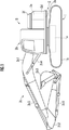
図1の側面図及び図2の後側上方から見た斜視図に示すように、油圧ショベルSは、下部走行体1と、下部走行体1に旋回可能に搭載されている上部旋回体2(上部基体)とを備えている。 As shown in the side view of FIG. 1 and the perspective view seen from the rear upper side of FIG. 2, the hydraulic excavator S includes the lower traveling body 1 and the upper rotating body 2 (which is rotatably mounted on the lower traveling body 1). It is equipped with an upper substrate).
下部走行体1は、ロアフレーム1aと、ロアフレーム1aの両側に設けられた一対のクローラ1bとを備えている。クローラ1bは、油圧アクチュエータである走行用油圧モータによって駆動される。
The lower traveling body 1 includes a
なお、本発明の下部走行体は、ロアフレームとクローラとによって構成されたものに限定されるものではなく、上部基体を搭載可能であり、移動可能なものであればよい。例えば、下部走行体は、車輪で移動するものであってもよいし、脚式移動のものであってもよい。また、作業機械が水上で使用されるものである場合には、下部走行体は台船等であってもよい。 The lower traveling body of the present invention is not limited to the one composed of the lower frame and the crawler, and may be any as long as it can mount the upper substrate and can move. For example, the lower traveling body may be one that moves by wheels or one that moves by legs. Further, when the work machine is used on water, the lower traveling body may be a pontoon or the like.
上部旋回体2は、ロアフレーム1aに対して旋回自在に支持されているアッパーフレーム2aと、アッパーフレーム2aの前側に設けられている運転室2bと、運転室2bの側方に設けられている作業機2cと、運転室2b及び作業機2cの後方に搭載されているカウンタウエイト2dと、アッパーフレーム2aとカウンタウエイト2dとで画成されている機械室2eとを有している。
The upper
運転室2bには、運転者が作業機2cの運動、上部旋回体2の旋回、及び、下部走行体1の移動を操作するための各種レバー(不図示)等、油圧ショベルSを操作するための各種機器が設けられている。
In the driver's
作業機2cは、上部旋回体2のアッパーフレーム2aに回動自在に連結されているブーム2c1と、ブーム2c1に回動自在に連結されているアーム2c2と、アーム2c2に回動自在に連結されているバケット2c3とを有している。
The
また、作業機2cは、上部旋回体2のアッパーフレーム2a及びブーム2c1に両端が取り付けられているブームシリンダ2c4と、ブーム2c1及びアーム2c2に両端が取り付けられているアームシリンダ2c5と、アーム2c2及びバケット2c3に両端が取り付けられているバケットシリンダ2c6とを有している。
Further, the working
ブーム2c1は、上部旋回体2のアッパーフレーム2aに回動可能に軸支されており、その軸を支点として、ブームシリンダ2c4の伸縮動作によって回動する。アーム2c2は、ブーム2c1に回動可能に軸支されており、その軸を支点として、アームシリンダ2c5の伸縮動作によって回動する。バケット2c3は、アーム2c2に回動可能に軸支されており、その軸を支点として、バケットシリンダ2c6の伸縮動作によって回動する。
The boom 2c1 is rotatably supported by the
カウンタウエイト2dは、その重量によって、作業機2cとの間で、油圧ショベルS全体としてのバランスを保っている。カウンタウエイト2dの形状は、上部旋回体2のアッパーフレーム2aの後方部分の形状と一致するように湾曲した形状となっている。これにより、カウンタウエイト2dと運転室2b及び作業機2cとの間には、機械室2eとなる空間が形成されている。
The
機械室2eには、駆動源としてのエンジン、下部走行体1のクローラ1b及び上部旋回体2の作業機2cのアクチュエータ等に油圧を供給する油圧回路、エンジン及び油圧回路等にオイルを供給するためのオイルポンプ等が設置されている。
The
図3に示すように、機械室2eは、内部に収容されたエンジンのメンテナンス等のために、上部旋回体2の上面に設けられている開口部2e1を介して、その内部と外部とが連通されている。上部旋回体2には、開口部2e1を覆うようにして、開閉自在な(すなわち、図3Aに示す開いた状態と図3B示す閉じた状態とを変更自在な)カバー2f(機械室カバー)が設けられている。
As shown in FIG. 3, the
カバー2fの後側の端部には、ボルト等で構成されている回動連結具2f1が取り付けられている。カバー2fは、回動連結具2f1を介して、カウンタウエイト2dに対して回動可能に取り付けられている。一方、カバー2fの前側の端部には、後述するロック機構3を構成するロック爪31が取り付けられている。
A rotary connector 2f1 composed of bolts or the like is attached to the rear end of the
ロック機構3は、カバー2fを閉じた状態で解除可能に固定するための機構である。ロック機構3は、カバー2fに取り付けられているロック爪31と、機械室2eを画成しているアッパーフレーム2aに取り付けられているストライカ32とで構成されている。
The
なお、本発明のロック機構は、上部基体に設けられた機械室を覆う開閉自在な機械室カバーを閉じた状態で解除可能に固定するものである。そのため、対象となる機械室カバーは、上記のカバー2fのように、上方に向かって形成された開口部を、回動によって開放又は閉鎖するものに限定されるものではない。
The lock mechanism of the present invention fixes the openable and closable machine room cover provided on the upper substrate so as to be unlockable in a closed state. Therefore, the target machine room cover is not limited to the one that opens or closes the opening formed upward by rotation, as in the
例えば、上部基体の側面又は下面に設けられた開口部を覆う機械室カバーに適用してもよい。また、スライド又は取り外しによって、開放又は閉鎖を行うタイプの機械室カバーに適用してもよい。 For example, it may be applied to a machine room cover that covers an opening provided on the side surface or the lower surface of the upper substrate. It may also be applied to a machine room cover of the type that opens or closes by sliding or removing.
また、本発明のロック機構のロック爪及びストライカは、上記のようにカバー2f(機械室カバー)及び上部旋回体2(上部基体)のアッパーフレーム2aに設けたものにのみ限定されるものではなく、それぞれが機械室カバー及び上部基体のいずれか一方及び他方に設けられたものであればよい。
Further, the lock claw and striker of the lock mechanism of the present invention are not limited to those provided on the
例えば、ロック爪を上部基体に設け、ストライカを機械室カバーに設けるようにしてもよい。また、ロック爪及びストライカの一方を機械室カバーに設けた場合には、他方を上部基体に搭載されている運転室のフレーム、又は、作業機のフレームに設けてもよい。 For example, the lock claw may be provided on the upper substrate and the striker may be provided on the machine room cover. When one of the lock claw and the striker is provided on the machine room cover, the other may be provided on the frame of the driver's cab mounted on the upper substrate or the frame of the working machine.
図4に示すように、ロック爪31は、カバー2fの機械室2e側にボルトによって固定されている基体部31aと、基体部31aに対して回動可能に軸支されており、ストライカ32に係合する爪部31bと、基体部31aに取り付けられており、爪部31bを付勢する第1バネ31cとを有している。
As shown in FIG. 4, the
基体部31aは、機械室2eの内部で下方に向かって突出する一対の第1突起31a1(規制部)と、第1突起31a1よりもストライカ32の移動方向における後側で下方に向かって突出し、第1突起31a1と対向している一対の第2突起31a2(規制部)とを有している。
The
一対の第1突起31a1及び一対の第2突起31a2は、それぞれ左右方向で重なる位置に設けられている。そのため、図4においては、第1突起31a1及び第2突起31a2は、それぞれ手前側の1つのみが図示されている。 The pair of first protrusions 31a1 and the pair of second protrusions 31a2 are provided at positions where they overlap in the left-right direction. Therefore, in FIG. 4, only one of the first protrusion 31a1 and the second protrusion 31a2 is shown on the front side.
一対の第1突起31a1の一方とそれに対応する一対の第2突起31a2の一方との間には、カバー2fを閉じた状態で、後述するストライカ32の左右方向に延びるガイド棒32dの一端部又は他端部が挟み込まれている。
Between one of the pair of first protrusions 31a1 and one of the corresponding pair of second protrusions 31a2, one end of a
また、基体部31aには、カバー2fに取り付けた際にカバー2fに設けられた操作窓2f2に対応する位置に、貫通孔(不図示)が形成されている(図2参照)。そのため、機械室2eの内部と外部とは、貫通孔及び操作窓2f2を介して連通されている。
Further, the
爪部31bは、棒状の部材として形成されており、中央部で基体部31aに第1ボルトB1によって、回動可能に軸支されている。
The
爪部31bの下方側の先端部である第1端部31b1は、先端がストライカ側に向かって延設されているフック形状となっている。第1端部31b1の先端の掛止部分は、ストライカ32側に向かって延設されており、カバー2fを閉じた状態で後述するストライカ32のストライカ本体部32bに下方側から当接可能(すなわち、掛止可能)となっている。
The first end portion 31b1, which is the lower end portion of the
爪部31bの第1端部31b1とは反対側の第2端部31b2は、基体部31aに設けられた孔及びカバー2fの操作窓2f2を介して、外部に露出している(図2参照)。
The second end portion 31b2 of the
第1バネ31cは、爪部31bのフック形状の第1端部31b1を、ストライカ32側に(すなわち、ロック爪31とストライカ32との掛止状態を維持する方向に)付勢している。
The
カバー2fを空ける際には、まず、カバー2fの操作窓2f2から露出している爪部31bの第2端部31b2を移動させることによって、爪部31bの第2端部31b2とは反対側の第1端部31b1を第1バネ31cの付勢力に抗して移動させ、第1端部31b1とストライカ32との掛止を解除し、その後、カバー2fを回動させて移動させる。
When opening the
なお、本発明におけるロック爪は、上記のように爪部31b全体を回動させることによって、フック形状の第1端部31b1の先端部をストライカ32に掛止するものに限定されるものではなく、ロック爪とストライカと掛止した状態を固定して、ロック状態を実現できるものであればよい。
The lock claw in the present invention is not limited to the one in which the tip end portion of the hook-shaped first end portion 31b1 is hooked on the
例えば、爪部に代わり板状の掛止部材を採用し、その掛止部材全体をスライド可能に構成して、掛止部材とストライカとが重なる状態(すなわち、機械室カバーの開閉動作を阻止する状態)と、重なっていない状態(すなわち、機械室カバーの開閉動作が自由に行われる状態)とを切り替え可能なロック機構として構成してもよい。 For example, a plate-shaped hooking member is used instead of the claw portion, and the entire hooking member is slidably configured to prevent the hooking member and the striker from overlapping (that is, the opening / closing operation of the machine room cover). It may be configured as a lock mechanism capable of switching between a state) and a non-overlapping state (that is, a state in which the opening and closing operation of the machine room cover is freely performed).
図4のロック機構の要部を示す側面図、及び、図5のストライカ32の分解斜視図に示すように、ストライカ32は、上部旋回体2のアッパーフレーム2aの機械室2e側に第2ボルトB2によって固定されているストライカホルダ32aと、ストライカホルダ32aに前後方向に移動自在に保持されており、ロック爪31が掛止するストライカ本体部32bと、ストライカホルダ32aとストライカ本体部32bとの間に設置されている一対の第2バネ32c(付勢部材)(図6参照)と、ストライカ本体部32bに取り付けられている棒状のガイド棒32d(規制部)とを備えている。
As shown in the side view showing the main part of the lock mechanism of FIG. 4 and the exploded perspective view of the
ストライカホルダ32aは、上下方向に延びる板状の第1固定部32a1と、第1固定部32a1の上端部から左右方向一方側に延びる板状の第2固定部32a2と、第2固定部32a2の第1固定部32a1とは反対側の端部の下方側に設けられている板状のガイド部32a3と、第2固定部32a2の略中央下方側に設けられている板状の抑え部32a4と、第2固定部32a2と抑え部32a4との間に配置されているスペーサ32a5とを有している。
The
第1固定部32a1には孔が形成されており、第1固定部32a1は、その孔に挿入される第2ボルトB2によって、上部旋回体2のアッパーフレーム2aの側壁の機械室2e側の面に固定される。
A hole is formed in the first fixing portion 32a1, and the first fixing portion 32a1 is formed by a second bolt B2 inserted into the hole to form a surface of the side wall of the
ガイド部32a3は、第2固定部32a2の第1固定部32a1側とは反対側の端部の下方側に、ストライカ本体部32bの移動方向に沿って延設されている。
The guide portion 32a3 extends along the moving direction of the striker
抑え部32a4は、スペーサ32a5を介して、第1固定部32a1と第2固定部32a2とガイド部32a3との間に、前後方向に延びる筒状の空間を形成している。ストライカ本体部32bは、この空間に移動可能に収容されている。
The holding portion 32a4 forms a tubular space extending in the front-rear direction between the first fixing portion 32a1, the second fixing portion 32a2, and the guide portion 32a3 via the spacer 32a5. The striker
スペーサ32a5は、ストライカ32の組立後の状態で、後述するストライカ本体部32bの孔部32b1の内部に位置する(図6参照)。そのため、スペーサ32a5は、ストライカ本体部32bが収容される空間を形成しているだけでなく、ストライカ本体部32bの抜け落ちを防止している。
The spacer 32a5 is located inside the hole 32b1 of the striker
第2固定部32a2、抑え部32a4及びスペーサ32a5には、対応する位置に上下方向に貫通する孔が形成されている。第2固定部32a2、抑え部32a4及びスペーサ32a5は、この穴に挿入された第3ボルトB3によって、相互に固定されている。 The second fixing portion 32a2, the holding portion 32a4, and the spacer 32a5 are formed with holes penetrating in the vertical direction at corresponding positions. The second fixing portion 32a2, the holding portion 32a4, and the spacer 32a5 are fixed to each other by the third bolt B3 inserted into the hole.
図6に示すように、ストライカ本体部32bは、略矩形の板状の部材であり、その略中央部には、略矩形の孔部32b1が形成されている。
As shown in FIG. 6, the striker
ストライカホルダ32aに保持された状態において、ストライカ本体部32bの後方となる端部には、ロック爪31の爪部31bのフック形状の第1端部31b1が、下方側から当接可能となっている(図5参照)。
In the state of being held by the
孔部32b1は、ストライカホルダ32aの略矩形のスペーサ32a5を挿入可能な大きさの略矩形の孔として形成されている。
The hole portion 32b1 is formed as a substantially rectangular hole having a size into which a substantially rectangular spacer 32a5 of the
孔部32b1の前後方向の幅はスペーサ32a5よりも大きく形成されている。そのため、前後方向における孔部32b1の端縁とスペーサ32a5の端縁との間には所定の間隔が形成されている。この間隔(すなわち、ストライカ本体部32bの最大移動量)は、ストライカ本体部32bの通常時の移動量よりも大きく形成されている。そのため、スペーサ32a5によって、ストライカ本体部32bの移動が制限されることはない。
The width of the hole portion 32b1 in the front-rear direction is formed to be larger than that of the spacer 32a5. Therefore, a predetermined distance is formed between the edge of the hole 32b1 and the edge of the spacer 32a5 in the front-rear direction. This interval (that is, the maximum movement amount of the striker
孔部32b1の左右方向の幅は、スペーサ32a5よりもわずかに大きく形成されている。ストライカ本体部32bは、孔部32b1の左右方向一方側の部分をストライカホルダ32aの第1固定部32a1とスペーサ32a5とに挟まれるとともに、他方側の部分をガイド部32a3とスペーサ32a5とに挟まれることによって、移動時における左右方向のがたつきが抑制されている。
The width of the hole portion 32b1 in the left-right direction is formed to be slightly larger than that of the spacer 32a5. In the striker
第2バネ32cは、前後方向における孔部32b1の端縁とスペーサ32a5の端縁との間に設けられている。第2バネ32cは、ストライカホルダ32aに対するストライカ本体部32b(ひいては、ストライカ本体部32bに取り付けられているガイド棒32d)の位置が所定となるように、スペーサ32a5に対してストライカ本体部32bを前後方向に付勢している。
The
これにより、カバー2fを閉じる際に、後述する外れ防止機構を構成している第1突起31a1と第2突起31a2との間に、ガイド棒32dを容易に案内することができるようになっている。その結果、第1突起31a1と第2突起31a2との間の間隔を小さく形成することができるようになっている。ひいては、外れ防止機構全体としての小型化を図ることができるようになっている。
As a result, when the
図5に示すように、ガイド棒32dは、左右方向に延びる棒状の部材によって形成されている。図4に示すように、ガイド棒32dは、ストライカ本体部32bの上方に取り付けられている。
As shown in FIG. 5, the
具体的には、ガイド棒32dの取付位置は、ストライカホルダ32aの第2固定部32a2よりも後方、且つ、ストライカ本体部32bが移動しても第2固定部32a2に当接しない位置となっている。すなわち、ガイド棒32bは、ストライカホルダ32aによって移動が規制されない位置に取り付けられている。
Specifically, the mounting position of the
ガイド棒32dは、カバー2fを閉じた状態で、ロック爪31の第1突起31a1と第2突起31a2とによって前後方向から挟み込まれている。
The
ここで、前後方向におけるガイド棒32dと第1突起31a1との間隔L1a、及び、ガイド棒32dと第2突起31a2との間隔L1bを足し合わせた長さは、ストライカ本体部32bに対し、ロック爪31の爪部31bのフック形状の第1端部31b1が掛止している部分の長さL2よりも小さくなるように構成されている。
Here, the total length of the distance L1a between the
すなわち、ガイド棒32dと第1突起31a1及び第2突起31a2とによって、掛止状態の外れ防止機構が構成されており、この外れ防止機構によって、後述するストライカ本体部32bの移動が、ロック爪31とストライカ32との掛止状態が維持される範囲で規制されている。
That is, the
なお、本発明におけるストライカは、上記のように構成したものに限定されるものではなく、ロック機構3に振動が加えられた際に、ロック爪とストライカとの掛止状態における掛止部分の相対的な位置を維持すべく、ロック爪の移動に伴って移動可能に構成されているものであればよい。
The striker in the present invention is not limited to the one configured as described above, and the relative of the hooked portion in the hooked state between the lock claw and the striker when vibration is applied to the
例えば、アッパーフレームにガイドレールを設け、単一の部材で構成されたストライカを、そのガイドレールに沿って移動可能に係合させたものであってもよい。 For example, a guide rail may be provided on the upper frame, and a striker composed of a single member may be movably engaged along the guide rail.
次に、油圧ショベルSが作業を行っている際に生じる機械振動等の振動によって、掛止状態にある(すなわち、当接している)ロック機構3に対し振動が加わった場合におけるロック機構3の挙動について説明する。
Next, when the
下部走行体1のクローラ1bを作動させて移動した場合、又は、作業機2cによって作業を行った場合等には、上部旋回体2に対し、振動が加わることになる。このとき、上部旋回体2のアッパーフレーム2aとカウンタウエイト2dとは独立した別の部材であるので、同一の振動源からの振動が加えられた場合であっても、発生する振動(例えば、その振動の周期等)は、各々で異なるものとなる。
When the
ここで、カバー2fを固定するためのロック機構3は、カウンタウエイト2dに回動連結具2f1を介してカバー2fに取り付けられているロック爪31と、アッパーフレーム2aに取り付けられているストライカ32とで構成されている。
Here, the
そのため、上部旋回体2に対し振動が加えられた際には、掛止状態にある(すなわち、当接している)ロック爪31とストライカ32とが相対的に移動して(すなわち、相対位置が変化して)、それらに摩耗及び衝突が生じてしまうという問題があった。
Therefore, when vibration is applied to the
特に、ロック爪31及びストライカ32のいずれか一方のみが移動したり、それぞれが異なる方向に移動したりすることによって、ロック爪31及びストライカ32の各々に異なる振動が加えられた場合には、摩耗及び衝突が生じる可能性が高くなる。
In particular, when only one of the
そのような摩耗及び衝突が生じると、ロック機構3のロック性能が十分に発揮できなくなったり、ロック機構3を構成する各部品に破損が生じてしまったりするおそれがあった。
If such wear and collision occur, the locking performance of the
そこで、ロック機構3では、ストライカ本体部32bとロック爪31のフック形状の第1端部31b1との掛止状態における相対位置を維持すべく、ストライカ32のストライカ本体部32bを、第1端部31b1の移動に伴って前後方向に移動可能に構成している。
Therefore, in the
具体的には、ロック爪31の爪部31bのフック形状の第1端部31b1と、それが掛止されているストライカ32のストライカ本体部32bとの相対位置を維持しようとする力(例えば、それらの間の摩擦による保持力)よりも、ストライカ32のストライカホルダ32aに対し、ストライカ本体部32bを移動させるために必要な力(例えば、それらの間で生じる摩擦による保持力)が、小さくなるように構成されている。
Specifically, a force for maintaining a relative position between the hook-shaped first end portion 31b1 of the
さらに、ストライカ32の内部に第2バネ32cを設け、ストライカ32側における振動を吸収できるようにしている。
Further, a
これにより、機械振動等の振動がロック機構3に加えられたとしても、その振動は、ストライカホルダ32aに対するストライカ本体部32bの移動によって吸収される。その結果、掛止状態における掛止部分の相対位置が維持される。
As a result, even if vibration such as mechanical vibration is applied to the
したがって、油圧ショベルSによれば、掛止状態でロック機構3に振動が加えられても、ロック機構3を構成する部品の掛止状態における掛止部分の相対位置が維持されるので、それらの摩耗を抑制することができる。
Therefore, according to the hydraulic excavator S, even if vibration is applied to the
なお、ロック爪31とストライカ32との相対位置を維持しようとする力は、必ずしも摩擦による保持力である必要はない。例えば、それらの当接面に係止するための突起等を設けてもよい。また、摩擦による保持力を用いる場合には、バネ等の付勢力によってそれらを相互に強く当接させて、その保持力が強まるようにしてもよい。
The force for maintaining the relative position between the
また、ロック爪31とストライカ32との相対位置は、必ずしも常に完全に固定されている必要はなく、わずかにでもその相対位置が維持できればよい。わずかにでもその相対位置が維持できれば、その維持がなされた分だけ、摩耗を抑制できるためである。
Further, the relative positions of the
ところで、通常想定される振動を超えるような大きな振動がロック機構3に加わってしまった場合等には、ストライカ32のストライカ本体部32bとロック爪31の第1端部31b1とが相対的に大きく(具体的には、ストライカ本体部32bに対し、フック形状の第1端部31b1が掛止している部分の長さL2(図4参照)より)移動してしまい、ストライカ32とロック爪31との掛止が解除されてしまうおそれが生じる。
By the way, when a large vibration exceeding the normally expected vibration is applied to the
しかし、油圧ショベルSでは、ガイド棒32dと第1突起31a1及び第2突起31a2とによって、掛止状態の外れ防止機構が構成されており、この外れ防止機構によって、ストライカ本体部32bの移動が、ロック爪31とストライカ32との掛止状態が維持される範囲で規制されている。
However, in the hydraulic excavator S, the
これにより、通常想定される振動を超えるような大きな振動がロック機構3に加わってしまった場合等であっても、不意の掛止の解除は防止されるようになっている。
As a result, even when a large vibration exceeding the normally expected vibration is applied to the
また、油圧ショベルSでは、ストライカ本体部32bの移動可能な量が、ストライカ32の組立誤差よりも大きくなるように設定されている。これにより、ストライカ32は、組み立てる際における微細な調整が不要となっており、工数を削減して、製造コストを抑えることができるようになっている。
Further, in the hydraulic excavator S, the movable amount of the striker
また、ストライカ本体部32bの移動可能な量は、ロック機構3の構造、上部旋回体2に加えられる振動の種類等に基づいて、実験等によって得られた予測される振動量(すなわち、ロック爪31に対するストライカ32の移動量)に応じた大きさになるように設定されている。これにより、移動可能な量を適切な範囲に抑えて、ロック機構3の大型化が抑制されている。
Further, the movable amount of the striker
以上、図示の実施形態について説明したが、本発明はこのような形態に限られるものではない。 Although the illustrated embodiment has been described above, the present invention is not limited to such an embodiment.
例えば、上記実施形態においては、ガイド棒32dと規制部(第1突起31a1及び第2突起31a2)とによって、掛止状態の外れ防止機構が構成されている。しかし、本発明のロック機構はそのような構成に限定されるものではない。
For example, in the above embodiment, the
例えば、ストライカ本体部のロック爪と係合する側の端部とは反対側の端部と、その端部に対向するようにストライカホルダに設けた突起とのみによって、外れ防止機構を構成してもよい。また、ロック爪の回動を規制するように機械室カバーに突起をもうけてもよい。さらに、ロック機構に加えられる振動に対し、ストライカ又はロック爪の移動可能な量を十分に大きく設定できる場合等には、外れ防止機構そのものを省略してもよい。 For example, the disengagement prevention mechanism is configured only by the end portion on the side opposite to the end portion on the side that engages with the lock claw of the striker main body and the protrusion provided on the striker holder so as to face the end portion. May be good. Further, a protrusion may be provided on the machine room cover so as to restrict the rotation of the lock claw. Further, when the movable amount of the striker or the lock claw can be set sufficiently large with respect to the vibration applied to the lock mechanism, the disengagement prevention mechanism itself may be omitted.
また、上記実施形態においては、ストライカ32の内部に、ストライカ32に加えられた振動を吸収するための付勢部材として第2バネ32cを配置している。しかし、本発明のロック機構はそのような構成に限定されるものではない。例えば、ストライカ本体部の移動のみによって十分に振動を吸収できる場合等には、付勢部材を省略してもよい。
Further, in the above embodiment, the
1…下部走行体、1a…ロアフレーム、1b…クローラ、2…上部旋回体(上部基体)、2a…アッパーフレーム、2b…運転室、2c…作業機、2c1…ブーム、2c2…アーム、2c3…バケット、2c4…ブームシリンダ、2c5…アームシリンダ、2c6…バケットシリンダ、2d…カウンタウエイト、2e…機械室、2e1…開口部、2f…カバー(機械室カバー)、2f1…回動連結具、2f2…操作窓、3…ロック機構、31…ロック爪、31a…基体部、31a1…第1突起(規制部)、31a2…第2突起(規制部)、31b…爪部、31b1…第1端部、31b2…第2端部、31c…第1バネ、32…ストライカ、32a…ストライカホルダ、32a1…第1固定部、32a2…第2固定部、32a3…ガイド部、32a4…抑え部、32a5…スペーサ、32b…ストライカ本体部、32b1…孔部、32c…第2バネ(付勢部材)、32d…ガイド棒、B1…第1ボルト、B2…第2ボルト、B3…第3ボルト、S…油圧ショベル。 1 ... Lower traveling body, 1a ... Lower frame, 1b ... Crawler, 2 ... Upper swivel body (upper base), 2a ... Upper frame, 2b ... Driver's cab, 2c ... Working machine, 2c1 ... Boom, 2c2 ... Arm, 2c3 ... Bucket, 2c4 ... Boom cylinder, 2c5 ... Arm cylinder, 2c6 ... Bucket cylinder, 2d ... Counter weight, 2e ... Machine room, 2e1 ... Opening, 2f ... Cover (machine room cover), 2f1 ... Rotating connector, 2f2 ... Operation window, 3 ... Lock mechanism, 31 ... Lock claw, 31a ... Base part, 31a1 ... First protrusion (regulatory part), 31a2 ... Second protrusion (regulatory part), 31b ... Claw part, 31b1 ... First end part, 31b2 ... 2nd end, 31c ... 1st spring, 32 ... striker, 32a ... striker holder, 32a1 ... 1st fixing part, 32a2 ... 2nd fixing part, 32a3 ... guide part, 32a4 ... holding part, 32a5 ... spacer, 32b ... Striker body, 32b1 ... Hole, 32c ... Second spring (urging member), 32d ... Guide rod, B1 ... 1st bolt, B2 ... 2nd bolt, B3 ... 3rd bolt, S ... Hydraulic excavator.
Claims (4)
前記ロック機構は、ロック爪と、前記ロック爪が掛止されるストライカとで構成され、
前記ロック爪は、前記ストライカに掛止及び解放する方向に移動自在であり、
前記ストライカは、前記上部基体及び前記機械室カバーのいずれか一方に固定されているストライカホルダと、前記ストライカホルダに移動自在に保持され、前記ロック爪が掛止するストライカ本体部とを有し、
前記ストライカホルダは、前記上部基体及び前記機械室カバーのいずれか一方に固定されている固定部と、前記固定部から離間して配置されている抑え部と、前記固定部と前記抑え部との間に配置されているスペーサとを有し、
前記ストライカ本体部は、前記固定部と前記抑え部との間に配置され、且つ、前記スペーサが挿入さていれる孔部を有し、
掛止状態における前記ロック爪と前記ストライカとの相対位置を維持すべく、前記ロック爪の移動に伴って、前記ストライカ本体部が前記ロック爪に対して離間及び接近する方向に移動自在となるように、前記孔部の該方向における幅は、前記スペーサの該方向における幅よりも大きく形成されていることを特徴とする作業機械。 The lower traveling body, the upper base mounted on the lower traveling body, the openable and closable machine room cover that covers the machine room provided on the upper base, and the machine room cover that can be released and fixed in a closed state. A work machine equipped with a lock mechanism
The locking mechanism includes a lock pawl, the locking pawl is composed of the striker to be latched,
The lock claw is movable in a direction of hooking and releasing the striker.
The striker has a striker holder fixed to either one of the upper substrate and the machine room cover, and a striker main body portion movably held by the striker holder and hooked by the lock claw.
The striker holder includes a fixing portion fixed to either one of the upper substrate and the machine room cover, a holding portion arranged apart from the fixing portion, and the fixing portion and the holding portion. Has a spacer placed between
The striker main body portion has a hole portion that is arranged between the fixing portion and the holding portion and into which the spacer is inserted.
To maintain the locking pawl in the hooking state of the relative position between the striker, with the movement of the locking pawl, so that the striker body portion is movable in a direction away and closer to the locking pawl the width in the direction of the hole portion, the working machine characterized that you have is larger than the width in the direction of the spacer.
前記ストライカホルダは、前記方向に沿って延設されているガイド部を有し、The striker holder has a guide portion extending along the direction.
前記ガイド部は、前記固定部及び前記抑え部とともに、前記ストライカホルダを収容する前記方向に延びる筒状の空間を形成していることを特徴とする作業機械。A work machine characterized in that the guide portion, together with the fixing portion and the holding portion, forms a tubular space extending in the direction for accommodating the striker holder.
前記ロック機構は、前記ストライカの移動を前記ロック爪と前記ストライカとの掛止状態が維持される範囲に規制する規制部を備えていることを特徴とする作業機械。 In the work machine according to claim 1 or 2.
The locking mechanism, working machine, characterized in that the move before kissing Toraika and a regulating portion for regulating the range in which the latching state is maintained between the striker and the locking pawl.
前記ロック機構は、前記ストライカの移動を規制して、所定の位置に位置するように付勢する付勢部材を備えていることを特徴とする作業機械。 In the work machine according to any one of claims 1 to 3.
The locking mechanism work machine prior to regulate the move kiss Toraika, characterized in that it comprises a biasing member for biasing so as to be positioned in a predetermined position.
Priority Applications (1)
| Application Number | Priority Date | Filing Date | Title |
|---|---|---|---|
| JP2017116045A JP6911552B2 (en) | 2017-06-13 | 2017-06-13 | Work machine |
Applications Claiming Priority (1)
| Application Number | Priority Date | Filing Date | Title |
|---|---|---|---|
| JP2017116045A JP6911552B2 (en) | 2017-06-13 | 2017-06-13 | Work machine |
Publications (2)
| Publication Number | Publication Date |
|---|---|
| JP2019002165A JP2019002165A (en) | 2019-01-10 |
| JP6911552B2 true JP6911552B2 (en) | 2021-07-28 |
Family
ID=65006799
Family Applications (1)
| Application Number | Title | Priority Date | Filing Date |
|---|---|---|---|
| JP2017116045A Expired - Fee Related JP6911552B2 (en) | 2017-06-13 | 2017-06-13 | Work machine |
Country Status (1)
| Country | Link |
|---|---|
| JP (1) | JP6911552B2 (en) |
Family Cites Families (10)
| Publication number | Priority date | Publication date | Assignee | Title |
|---|---|---|---|---|
| JPH07263872A (en) * | 1994-03-18 | 1995-10-13 | Clarion Co Ltd | Operation part locking mechanism |
| JP3586149B2 (en) * | 1999-10-19 | 2004-11-10 | アイシン精機株式会社 | Lock device |
| JP2002129592A (en) * | 2000-10-25 | 2002-05-09 | Hitachi Constr Mach Co Ltd | Door apparatus for construction equipment |
| JP3858789B2 (en) * | 2002-08-29 | 2006-12-20 | コベルコ建機株式会社 | Door lock device for construction machinery |
| JP2007077593A (en) * | 2005-09-12 | 2007-03-29 | Komatsu Ltd | Cab skylight opening and closing device |
| JP4907981B2 (en) * | 2005-12-26 | 2012-04-04 | 日立建機株式会社 | Opening and closing door fixing device |
| JP2009030416A (en) * | 2007-07-31 | 2009-02-12 | Renias:Kk | Sliding window lock structure |
| KR20130063278A (en) * | 2011-12-06 | 2013-06-14 | 볼보 컨스트럭션 이큅먼트 에이비 | Open and close device of engine hood of construction machine |
| EP2913442A4 (en) * | 2012-10-25 | 2016-08-03 | Volvo Constr Equip Ab | Hood opening and closing device for zero tail type construction machinery |
| JP6543095B2 (en) * | 2015-05-28 | 2019-07-10 | 日立建機株式会社 | Construction machinery |
-
2017
- 2017-06-13 JP JP2017116045A patent/JP6911552B2/en not_active Expired - Fee Related
Also Published As
| Publication number | Publication date |
|---|---|
| JP2019002165A (en) | 2019-01-10 |
Similar Documents
| Publication | Publication Date | Title |
|---|---|---|
| US8079438B2 (en) | Seat for heavy equipment having buffer means in forward and backward directions | |
| KR101317744B1 (en) | Engine hood for construction machine | |
| JP4343900B2 (en) | Construction machinery | |
| US10961689B2 (en) | Small-sized construction machine with heat exchanger cover | |
| CN104703867A (en) | Lock device for hood of engine room of construction machine | |
| TW201946572A (en) | Slide rail assembly and slide rail kit thereof | |
| EP3719214B1 (en) | Cab for working machine, and working machine | |
| JP6911552B2 (en) | Work machine | |
| JP2009007764A (en) | Construction machinery | |
| JP3808813B2 (en) | Arm fall control device for work vehicle | |
| CN110821313B (en) | Door lock releasing device for construction machine | |
| JP5053212B2 (en) | Engine installation structure of loader work machine | |
| JP5822821B2 (en) | Construction machinery | |
| JP4908392B2 (en) | Construction machinery | |
| JP6603646B2 (en) | Small excavator | |
| JP2011012509A (en) | Construction machine | |
| JP2005313818A (en) | Opening/closing device in construction machine | |
| JP5241443B2 (en) | Opening and closing structure of movable fender | |
| JP7059856B2 (en) | Lock mechanism for work machines and work machines | |
| JPWO2018012047A1 (en) | Construction machine cab | |
| JP6864659B2 (en) | Work machine | |
| JP4359776B2 (en) | Opening and closing door fixing device | |
| JPH11336124A (en) | Construction machine | |
| US20240426078A1 (en) | Work machine | |
| JP4698455B2 (en) | Front structure of work vehicle |
Legal Events
| Date | Code | Title | Description |
|---|---|---|---|
| A621 | Written request for application examination |
Free format text: JAPANESE INTERMEDIATE CODE: A621 Effective date: 20200114 |
|
| A977 | Report on retrieval |
Free format text: JAPANESE INTERMEDIATE CODE: A971007 Effective date: 20201120 |
|
| A131 | Notification of reasons for refusal |
Free format text: JAPANESE INTERMEDIATE CODE: A131 Effective date: 20201201 |
|
| A521 | Request for written amendment filed |
Free format text: JAPANESE INTERMEDIATE CODE: A523 Effective date: 20210118 |
|
| TRDD | Decision of grant or rejection written | ||
| A01 | Written decision to grant a patent or to grant a registration (utility model) |
Free format text: JAPANESE INTERMEDIATE CODE: A01 Effective date: 20210608 |
|
| A61 | First payment of annual fees (during grant procedure) |
Free format text: JAPANESE INTERMEDIATE CODE: A61 Effective date: 20210621 |
|
| R150 | Certificate of patent or registration of utility model |
Ref document number: 6911552 Country of ref document: JP Free format text: JAPANESE INTERMEDIATE CODE: R150 |
|
| LAPS | Cancellation because of no payment of annual fees |