JP6908036B2 - Light source device and projection display device - Google Patents
Light source device and projection display device Download PDFInfo
- Publication number
- JP6908036B2 JP6908036B2 JP2018518106A JP2018518106A JP6908036B2 JP 6908036 B2 JP6908036 B2 JP 6908036B2 JP 2018518106 A JP2018518106 A JP 2018518106A JP 2018518106 A JP2018518106 A JP 2018518106A JP 6908036 B2 JP6908036 B2 JP 6908036B2
- Authority
- JP
- Japan
- Prior art keywords
- light
- wavelength
- light source
- phosphor
- wavelength region
- Prior art date
- Legal status (The legal status is an assumption and is not a legal conclusion. Google has not performed a legal analysis and makes no representation as to the accuracy of the status listed.)
- Active
Links
Images


Classifications
-
- G—PHYSICS
- G03—PHOTOGRAPHY; CINEMATOGRAPHY; ANALOGOUS TECHNIQUES USING WAVES OTHER THAN OPTICAL WAVES; ELECTROGRAPHY; HOLOGRAPHY
- G03B—APPARATUS OR ARRANGEMENTS FOR TAKING PHOTOGRAPHS OR FOR PROJECTING OR VIEWING THEM; APPARATUS OR ARRANGEMENTS EMPLOYING ANALOGOUS TECHNIQUES USING WAVES OTHER THAN OPTICAL WAVES; ACCESSORIES THEREFOR
- G03B21/00—Projectors or projection-type viewers; Accessories therefor
- G03B21/14—Details
- G03B21/20—Lamp housings
- G03B21/2006—Lamp housings characterised by the light source
- G03B21/2033—LED or laser light sources
- G03B21/204—LED or laser light sources using secondary light emission, e.g. luminescence or fluorescence
-
- G—PHYSICS
- G03—PHOTOGRAPHY; CINEMATOGRAPHY; ANALOGOUS TECHNIQUES USING WAVES OTHER THAN OPTICAL WAVES; ELECTROGRAPHY; HOLOGRAPHY
- G03B—APPARATUS OR ARRANGEMENTS FOR TAKING PHOTOGRAPHS OR FOR PROJECTING OR VIEWING THEM; APPARATUS OR ARRANGEMENTS EMPLOYING ANALOGOUS TECHNIQUES USING WAVES OTHER THAN OPTICAL WAVES; ACCESSORIES THEREFOR
- G03B21/00—Projectors or projection-type viewers; Accessories therefor
- G03B21/14—Details
- G03B21/20—Lamp housings
- G03B21/2006—Lamp housings characterised by the light source
-
- F—MECHANICAL ENGINEERING; LIGHTING; HEATING; WEAPONS; BLASTING
- F21—LIGHTING
- F21S—NON-PORTABLE LIGHTING DEVICES; SYSTEMS THEREOF; VEHICLE LIGHTING DEVICES SPECIALLY ADAPTED FOR VEHICLE EXTERIORS
- F21S2/00—Systems of lighting devices, not provided for in main groups F21S4/00 - F21S10/00 or F21S19/00, e.g. of modular construction
-
- F—MECHANICAL ENGINEERING; LIGHTING; HEATING; WEAPONS; BLASTING
- F21—LIGHTING
- F21V—FUNCTIONAL FEATURES OR DETAILS OF LIGHTING DEVICES OR SYSTEMS THEREOF; STRUCTURAL COMBINATIONS OF LIGHTING DEVICES WITH OTHER ARTICLES, NOT OTHERWISE PROVIDED FOR
- F21V7/00—Reflectors for light sources
- F21V7/22—Reflectors for light sources characterised by materials, surface treatments or coatings, e.g. dichroic reflectors
- F21V7/24—Reflectors for light sources characterised by materials, surface treatments or coatings, e.g. dichroic reflectors characterised by the material
-
- F—MECHANICAL ENGINEERING; LIGHTING; HEATING; WEAPONS; BLASTING
- F21—LIGHTING
- F21V—FUNCTIONAL FEATURES OR DETAILS OF LIGHTING DEVICES OR SYSTEMS THEREOF; STRUCTURAL COMBINATIONS OF LIGHTING DEVICES WITH OTHER ARTICLES, NOT OTHERWISE PROVIDED FOR
- F21V9/00—Elements for modifying spectral properties, polarisation or intensity of the light emitted, e.g. filters
- F21V9/30—Elements containing photoluminescent material distinct from or spaced from the light source
-
- G—PHYSICS
- G02—OPTICS
- G02F—OPTICAL DEVICES OR ARRANGEMENTS FOR THE CONTROL OF LIGHT BY MODIFICATION OF THE OPTICAL PROPERTIES OF THE MEDIA OF THE ELEMENTS INVOLVED THEREIN; NON-LINEAR OPTICS; FREQUENCY-CHANGING OF LIGHT; OPTICAL LOGIC ELEMENTS; OPTICAL ANALOGUE/DIGITAL CONVERTERS
- G02F1/00—Devices or arrangements for the control of the intensity, colour, phase, polarisation or direction of light arriving from an independent light source, e.g. switching, gating or modulating; Non-linear optics
- G02F1/01—Devices or arrangements for the control of the intensity, colour, phase, polarisation or direction of light arriving from an independent light source, e.g. switching, gating or modulating; Non-linear optics for the control of the intensity, phase, polarisation or colour
- G02F1/13—Devices or arrangements for the control of the intensity, colour, phase, polarisation or direction of light arriving from an independent light source, e.g. switching, gating or modulating; Non-linear optics for the control of the intensity, phase, polarisation or colour based on liquid crystals, e.g. single liquid crystal display cells
- G02F1/133—Constructional arrangements; Operation of liquid crystal cells; Circuit arrangements
- G02F1/1333—Constructional arrangements; Manufacturing methods
- G02F1/1335—Structural association of cells with optical devices, e.g. polarisers or reflectors
-
- G—PHYSICS
- G03—PHOTOGRAPHY; CINEMATOGRAPHY; ANALOGOUS TECHNIQUES USING WAVES OTHER THAN OPTICAL WAVES; ELECTROGRAPHY; HOLOGRAPHY
- G03B—APPARATUS OR ARRANGEMENTS FOR TAKING PHOTOGRAPHS OR FOR PROJECTING OR VIEWING THEM; APPARATUS OR ARRANGEMENTS EMPLOYING ANALOGOUS TECHNIQUES USING WAVES OTHER THAN OPTICAL WAVES; ACCESSORIES THEREFOR
- G03B21/00—Projectors or projection-type viewers; Accessories therefor
- G03B21/14—Details
-
- G—PHYSICS
- G03—PHOTOGRAPHY; CINEMATOGRAPHY; ANALOGOUS TECHNIQUES USING WAVES OTHER THAN OPTICAL WAVES; ELECTROGRAPHY; HOLOGRAPHY
- G03B—APPARATUS OR ARRANGEMENTS FOR TAKING PHOTOGRAPHS OR FOR PROJECTING OR VIEWING THEM; APPARATUS OR ARRANGEMENTS EMPLOYING ANALOGOUS TECHNIQUES USING WAVES OTHER THAN OPTICAL WAVES; ACCESSORIES THEREFOR
- G03B33/00—Colour photography, other than mere exposure or projection of a colour film
- G03B33/06—Colour photography, other than mere exposure or projection of a colour film by additive-colour projection apparatus
-
- G—PHYSICS
- G03—PHOTOGRAPHY; CINEMATOGRAPHY; ANALOGOUS TECHNIQUES USING WAVES OTHER THAN OPTICAL WAVES; ELECTROGRAPHY; HOLOGRAPHY
- G03B—APPARATUS OR ARRANGEMENTS FOR TAKING PHOTOGRAPHS OR FOR PROJECTING OR VIEWING THEM; APPARATUS OR ARRANGEMENTS EMPLOYING ANALOGOUS TECHNIQUES USING WAVES OTHER THAN OPTICAL WAVES; ACCESSORIES THEREFOR
- G03B33/00—Colour photography, other than mere exposure or projection of a colour film
- G03B33/10—Simultaneous recording or projection
- G03B33/12—Simultaneous recording or projection using beam-splitting or beam-combining systems, e.g. dichroic mirrors
-
- H—ELECTRICITY
- H04—ELECTRIC COMMUNICATION TECHNIQUE
- H04N—PICTORIAL COMMUNICATION, e.g. TELEVISION
- H04N5/00—Details of television systems
- H04N5/74—Projection arrangements for image reproduction, e.g. using eidophor
Description
本開示は、プロジェクター等の投影表示装置に用いられる光源装置およびこれを備える投影表示装置に関する。 The present disclosure relates to a light source device used for a projection display device such as a projector and a projection display device including the light source device.
近年、画像をスクリーン等に投影して表示するプロジェクターは、会議室や教室、ホームシアター、劇場等のように幅広い場面で使用されている。プロジェクターでは、従来、明るさやコストパフォーマンスの観点から水銀ランプを主に用いていた。しかし、水銀ランプは、長期の使用においては定期的な交換が必要であり、点灯にも時間がかかる。そこで、プロジェクターの光源として、長寿命性、高機能付加等の観点から、長寿命であり色域の広い固体光源が注目されている。固体光源は、半導体のp/n接合による発光現象を用いた光源であり、LEDやレーザダイオード(LD)等がある。近年では、例えば特許文献1、2のような、特定の波長域の光を照射すると当該光とは異なる波長域の光を発光する蛍光体材料に対して固体光源により光を照射し、蛍光発光した光を利用する光源装置がプロジェクター等に利用されている。 In recent years, projectors that project and display images on screens and the like have been used in a wide range of situations such as conference rooms, classrooms, home theaters, and theaters. Conventionally, mercury lamps have been mainly used in projectors from the viewpoint of brightness and cost performance. However, mercury lamps need to be replaced regularly for long-term use, and it takes time to light up. Therefore, as a light source for a projector, a solid light source having a long life and a wide color gamut has been attracting attention from the viewpoint of long life and addition of high functionality. The solid-state light source is a light source that uses a light emission phenomenon due to a p / n junction of a semiconductor, and includes an LED, a laser diode (LD), and the like. In recent years, a phosphor material that emits light in a wavelength range different from that of the light when irradiated with light in a specific wavelength range, such as Patent Documents 1 and 2, is irradiated with light by a solid-state light source to emit fluorescence. A light source device that utilizes the generated light is used for a projector or the like.
ここで、プロジェクター用の光源としてはDCI規格やsRGB等に基づく映像表示機器の規格色域と白色を表示できることが望ましい。例えば、光源に、赤色波長域、緑色波長域および青色波長域それぞれの発光スペクトルを持たせることで、赤、緑、青の各原色およびこれらの原色を同時に点灯したときの白色において、上記の規格の近傍の色を表示させることができる。 Here, it is desirable that the light source for the projector can display the standard color gamut and white color of a video display device based on the DCI standard, sRGB, or the like. For example, by providing the light source with emission spectra of each of the red wavelength region, the green wavelength region, and the blue wavelength region, the above standards are used for the red, green, and blue primary colors and the white color when these primary colors are lit at the same time. It is possible to display the color in the vicinity of.
このような発光スペクトルを持つ光源は、例えば、赤、緑、青の各色を固体光源により出力して実現することも考えられるが、上記特許文献1、2のように蛍光体を用いて実現することも可能である。しかし、蛍光体を用いた場合には、赤色波長域、緑色波長域および青色波長域それぞれの発光スペクトルをバランスよく持たせることが難しく、特定の波長域の光量が不足することがあった。そこで、蛍光体を効率よく励起することができ、かつ、色再現性のよい光源装置を実現することが求められていた。 A light source having such an emission spectrum can be realized by outputting each color of red, green, and blue with a solid-state light source, for example, but it is realized by using a phosphor as in Patent Documents 1 and 2. It is also possible. However, when a phosphor is used, it is difficult to have a well-balanced emission spectrum for each of the red wavelength region, the green wavelength region, and the blue wavelength region, and the amount of light in a specific wavelength region may be insufficient. Therefore, it has been required to realize a light source device capable of efficiently exciting a phosphor and having good color reproducibility.
本開示によれば、第1波長域に含まれる第1波長の光を出射する第1光源と、第1波長域に含まれる、第1波長よりも短波長である第2波長の光を出射する第2光源と、第1光源から入射された第1波長の光と、第2光源から入射された第2波長の光とにより励起され、第2波長域の光を発光すると共に、第1波長の光および第2波長の光を透過させる蛍光体と、蛍光体と対向して設けられ、蛍光体から出射した光のうち第2波長の光を反射し、第1波長の光および第2波長域の光を透過させる波長選択部材と、を備える、光源装置が提供される。 According to the present disclosure, a first light source that emits light of the first wavelength included in the first wavelength region and light of a second wavelength included in the first wavelength region that is shorter than the first wavelength are emitted. a second light source for a light of the first wavelength incident from the first light source is excited by a light of a second wavelength that is incident from the second light source, the emitting light of the second wavelength band, first A phosphor that transmits light of a wavelength and a light of a second wavelength, and a phosphor that is provided opposite to the phosphor and reflects the light of the second wavelength among the light emitted from the phosphor, and the light of the first wavelength and the second wavelength. comprising a wavelength selecting member Ru transmits light in a wavelength range, the light source device is provided.
また、本開示によれば、光源部と、入射された光を変調し合成する光変調合成系と、光源部から出射された光を光変調合成系へ導く照明光学系と、光変調合成系から出射された画像を投射する投射光学系と、からなり、光源部は、第1波長域に含まれる第1波長の光を出射する第1光源と、第1波長域に含まれる、第1波長よりも短波長である第2波長の光を出射する第2光源と、第1光源から入射された第1波長の光と、第2光源から入射された第2波長の光とにより励起され、第2波長域の光を発光すると共に、第1波長の光および第2波長の光を透過させる蛍光体と、蛍光体と対向して設けられ、蛍光体から出射した光のうち第2波長の光を反射し、第1波長の光および第2波長域の光を透過させる波長選択部材と、を備える、投影表示装置が提供される。 Further, according to the present disclosure, a light source unit, a light modulation synthesis system that modulates and synthesizes incident light, an illumination optical system that guides light emitted from the light source unit to a light modulation synthesis system, and a light modulation synthesis system. It consists of a projection optical system that projects an image emitted from the light source, and a light source unit includes a first light source that emits light of the first wavelength included in the first wavelength region and a first light source included in the first wavelength region. a second light source for emitting a second wavelength light is shorter than the wavelength, the light of the first wavelength incident from the first light source is excited by a light of a second wavelength that is incident from the second light source , A phosphor that emits light in the second wavelength range and transmits light of the first wavelength and light of the second wavelength, and a second wavelength of the light emitted from the phosphor provided opposite to the phosphor. It reflects the light comprises a wavelength selecting member Ru transmits light of the light and the second wavelength band of the first wavelength, the projection display apparatus is provided.
以上説明したように本開示によれば、蛍光体を効率よく励起することができ、かつ、色再現性のよい光源装置を実現できる。なお、上記の効果は必ずしも限定的なものではなく、上記の効果とともに、または上記の効果に代えて、本明細書に示されたいずれかの効果、または本明細書から把握され得る他の効果が奏されてもよい。 As described above, according to the present disclosure, it is possible to realize a light source device capable of efficiently exciting a phosphor and having good color reproducibility. It should be noted that the above effects are not necessarily limited, and either in combination with or in place of the above effects, any of the effects shown herein, or any other effect that can be grasped from this specification. May be played.
以下に添付図面を参照しながら、本開示の好適な実施の形態について詳細に説明する。なお、本明細書及び図面において、実質的に同一の機能構成を有する構成要素については、同一の符号を付することにより重複説明を省略する。 Preferred embodiments of the present disclosure will be described in detail below with reference to the accompanying drawings. In the present specification and the drawings, components having substantially the same functional configuration are designated by the same reference numerals, so that duplicate description will be omitted.
なお、説明は以下の順序で行うものとする。
1.投影表示装置の概略構成
2.光源装置の構成
3.具体例
3.1.青色光による蛍光体励起
3.2.変形例
4.まとめThe explanations will be given in the following order.
1. 1. Outline configuration of projection display device 2. Configuration of light source device 3. Specific example 3.1. Excitation of phosphor by blue light 3.2. Modification example 4. summary
<1.投影表示装置の概略構成>
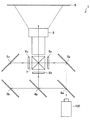
まず、図1を参照して、本開示の一実施形態に係る光源装置100を光源部として備える投影表示装置1の一構成例について説明する。図1は、本実施形態に係る光源装置100を備える投影表示装置1の一構成例を示す概略構成図である。<1. Outline configuration of projection display device>
First, with reference to FIG. 1, a configuration example of a projection display device 1 including a
図1に示す投影表示装置1は、3LCD(Liquid Crystal Display)方式のプロジェクターの一構成例である。3LCD方式のプロジェクターでは、光源部である光源装置100から出射された白色光を、赤、緑、青の三原色に分離し、3つのLCDをそれぞれ透過させることで、スクリーンS等の表示面に投影する画像を生成している。 The projection display device 1 shown in FIG. 1 is an example of a configuration of a 3LCD (Liquid Crystal Display) type projector. In a 3-LCD projector, white light emitted from a
より詳細には、光源装置100から出射した白色光は、例えば、青色波長域の光のみを透過し、その他の波長域の光を反射する第1反射ダイクロイックミラー4aに入射する。これにより、青色波長域の光は第1反射ダイクロイックミラー4aを透過して反射ミラー5a側へ進行する。そして、青色波長域の光は、反射ミラー5aにより反射され、青色用液晶パネル6aに入射する。 More specifically, the white light emitted from the
一方、第1反射ダイクロイックミラー4aにより反射されたその他の波長域の光は、第2反射ダイクロイックミラー4bへ入射する。第2反射ダイクロイックミラー4bは、緑色波長域の光のみを反射し、その他の波長域の光、すなわち赤色波長域の光を通過させる。第2反射ダイクロイックミラー4bにより反射された緑色波長域の光は、緑色用液晶パネル6bに入射する。また、第2反射ダイクロイックミラー4bを通過した赤色波長域の光は、反射ミラー5b、5cにより反射された後、赤色用液晶パネル6cへ入射する。 On the other hand, the light in the other wavelength range reflected by the first reflection
各色用の液晶パネル6a〜6cは、入力画像信号に応じてそれぞれに入射した光を変調し、RGBに対応する画像の信号光を生成する。液晶パネル6a〜6cには、例えば高温ポリシリコンTFTを用いた透過型液晶素子を使用してもよい。各液晶パネル6a〜6cにより変調された信号光は、ダイクロイックプリズム7に入射され、合成される。ダイクロイックプリズム7は、赤色の信号光および青色の信号光を反射し、緑色の信号光を透過させるように、4つの三角柱を組み合わせた直方体に形成されている。ダイクロイックプリズム7により合成された各色の信号光は投射レンズ8へ入射されて、スクリーンS等の表示面に画像として投影される。 The
投影表示装置1において、液晶パネル6a〜6cおよびダイクロイックプリズム7は入射された光を変調して合成する光変調合成系として機能するものである。また、反射ダイクロイックミラー4a、4b、反射ミラー5a〜5cは、光変調合成系を構成する液晶パネル6a〜6cに光源部である光源装置100からの光を導く照明光学系として機能するものである。そして、および投射レンズ8は、ダイクロイックプリズム7から出射された画像を投射する投射光学系として機能するものである。 In the projection display device 1, the
<2.光源装置の構成>
本実施形態に係る光源装置100は、蛍光体を所定の波長域の光により励起し、異なる波長域の光を発光させ、所望の色の光を生成し出射する。ここで、蛍光体を励起させる励起光の一部を、光源装置100から出射する光の一部として用いることも可能であるが、蛍光体を効率よく励起させる波長と、色再現性の観点から最適な波長とは異なる。そこで、本実施形態では、略同一の色を表す波長域の光を出射する光源を2つ設け、一方を蛍光体の励起用として用い、他方を色再現性用として用いる。<2. Configuration of light source device>
The
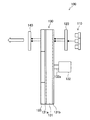
このような光源装置100は、例えば図2に示すように、光源110と、コリメータレンズ120と、波長変換部材130と、波長選択部材140とを含んでなる。 As shown in FIG. 2, for example, such a
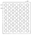
光源110は、第1波長域の光を出射する光源部である。光源110は、第1波長域に含まれる異なる2つの波長の光を出射可能に構成されている。光源110は、例えば複数のレーザダイオードからなるレーザダイオードアレイ等のアレイ光源であってもよい。光源110がレーザダイオードアレイであるときには、例えば図3に示すように、第1波長の光を出射する第1光源111と、第2波長の光を出射する第2光源113とを交互に配列して格子状に配置して構成してもよい。このように、第1光源111及び第2光源113をまとめて構成することで、光源装置100を小型化することができる。なお、第1光源111及び第2光源113の配置及び数は、図3に示す例に限定されるものではない。光源110から出射された異なる2つの波長の光は、コリメータレンズ120へ入射される。 The
コリメータレンズ120は、光源110が出射した光を平行光にし、波長変換部材130へ出射する光学部材である。コリメータレンズ120は、例えば光源110が図3に示したようなレーザダイオードアレイとして構成されている場合、レーザダイオードアレイを構成する各光源111、113にそれぞれ対応するコリメータレンズからなるレンズアレイとして構成してもよい。 The
波長変換部材130は、コリメータレンズ120を介して入射された光源110からの光の一部を、入射時の波長域とは異なる波長域の光に変換する部材である。光の波長域の変換には蛍光体が用いられ、例えば、波長変換部材130は透過型の蛍光体ホイールとして構成される。具体的には、波長変換部材130は、図2に示すように、基材131と、駆動部132と、蛍光体133とからなる。 The
基材131は、蛍光体133が積層される部材である。光源110から出射された光は、基材131を通過して、蛍光体133に入射する。このため、基材131は、光源110からの光が通過可能なように、サファイア等の透明部材により形成される。基材131は、例えば円板状に形成されており、その中心に駆動部132の回転軸132aが取り付けられている。駆動部132が回転軸132aを回転されることにより、基材131も回転させることができる。本実施形態の光源装置100のように、光源110としてレーザダイオードを用いる場合、点光源となるため、光源110からの光が出射された位置に熱が集中して高温となる。そこで、本実施形態に係る波長変換部材130のように回転可能とすることで、基材131における光の照射位置を分散させることができる。 The
基材131の、光源110からの光が入射する入射面には、光が蛍光体133へより多く入射するように、AR(Anti-Reflective)処理を施してもよい。例えば、基材131の入射面側に、光の反射を低減させる反射防止膜131bを設けてもよい。一方、基材131と蛍光体133との間には、蛍光体133にて発光した第2波長域の光が基材131側へ向かうのを防止するため、第2波長域の光を反射する反射膜131aを設けてもよい。このような反射膜131aを設けることで、蛍光体133により発光された第2波長域の光が基材131側へ出射するのを防止でき、第2波長域の光を確実に光源装置100から出射させることができる。 The incident surface of the
蛍光体133は、基材131に積層された蛍光体層である。蛍光体133は、例えば、基材131の光源110と反対側の面に設けられる。具体的には、例えば図2に示すように、円板状の基材131と同心の環状に蛍光体133を設けてもよい。蛍光体133は、例えば蛍光剤を混合させたバインダーをスクリーン印刷により基材131上に塗布することで設けられる。蛍光体133は、基材131を通過した光源110からの光によって励起され、入射した波長域の光とは異なる波長域の光を発光する。なお、蛍光体133は、光源110からの出射光のうち一部を透過させる。したがって、光源110から第1波長光及び第2波長光が蛍光体133に入射すると、第1波長域の第1波長光及び第2波長光と、蛍光体133が励起して発光した第2波長域の光とが出射される。 The
波長選択部材140は、波長変換部材130から出射された光のうち、第1波長域の第2波長光を反射し、第1波長域の第1波長光及び第2波長域の光を透過させる。波長選択部材140には、例えば反射ダイクロイックミラー等の光学部材を用いてもよい。波長選択部材140は、第2波長光を全反射してもよく、第2波長光のうち少なくとも一部のみを反射してもよい。波長選択部材140により反射させた第2波長光は蛍光体133側に向かい、蛍光体133に入射し、蛍光体133を励起させる。これにより、蛍光体133はさらに第2波長域の光を発光することができ、光源装置100から出射される光に第2波長域の光量を多くすることができる。このように、第2波長光は蛍光体133を励起させる励起光として使用される。したがって、第2波長光の波長を、蛍光体133に吸収されやすい波長とすることで、蛍光体133を効率よく励起させ、第2波長域の光を発光させることができる。 The
波長選択部材140を通過した光には、第1波長域の第1波長光と第2波長域の光とが含まれる。ここで、第1波長光は、蛍光体133に吸収される波長であるが、波長選択部材140を通過するため、光源装置100から最終的に出射される第1波長域の光の色を決定付ける光となる。そこで、第1波長域の光が表す色を正しく再現可能な波長の光とすることで、第1波長域の光が表す色の色再現性を高めることができ、光源装置100から出射される光の色をより所望の色に近づけることが可能となる。 The light that has passed through the
<3.具体例>
(3.1.青色光による蛍光体励起)
本実施形態に係る光源装置100の一具体例として、光源110として、青色波長域の光を発する青色レーザタイオードを用いる場合を考える。光源110は、図4に示すように、第1光源111から第1波長λb1の第1青色光を出射し、第2光源113から第2波長λb2の第2青色光を出射する。第1光源111は、青色の再現性のよい波長の光を出射する光源であり、第1波長λb1は例えば465nmとする。いずれも第1波長域である青色波長域(約400〜500nm)内の波長である。一方、第2光源113は、蛍光体133の励起光を出射する光源である。本例において、蛍光体133は、励起光によって緑色波長域の光と赤色波長域の光とを含む光を発光する黄色蛍光体である。そこで、第2波長λb2は黄色蛍光体に吸収されやすい波長、例えば445nmとする。<3. Specific example>
(3.1. Excitation of phosphor by blue light)
As a specific example of the
ここで、図5に、励起光の波長と黄色蛍光体の励起効率との関係を示す。励起効率は、波長445nmの光によって黄色蛍光体が励起されたときに発光する蛍光光量を基準として、各波長の光によって黄色蛍光体を励起したときの蛍光光量の比率を表している。図5に示すように、励起効率は励起光の波長が約445nmで最大となり、これより励起光の波長が長くなるほど励起効率は低下する。すなわち、第1波長λb1の光よりも最大励起効率となる波長に近い第2波長λb2の光の方が、黄色蛍光体の励起効率はよい。Here, FIG. 5 shows the relationship between the wavelength of the excitation light and the excitation efficiency of the yellow phosphor. The excitation efficiency represents the ratio of the amount of fluorescent light when the yellow phosphor is excited by the light of each wavelength, with reference to the amount of fluorescent light emitted when the yellow phosphor is excited by light having a wavelength of 445 nm. As shown in FIG. 5, the excitation efficiency is maximized when the wavelength of the excitation light is about 445 nm, and the longer the wavelength of the excitation light is, the lower the excitation efficiency is. That is, the excitation efficiency of the yellow phosphor is higher in the light having the second wavelength λ b2 , which is closer to the wavelength at which the maximum excitation efficiency is obtained, than in the light having the first wavelength λ b1.
図4に示すように、第1波長λb1の第1青色光及び第2波長λb2の第2青色光は、基材131を通過すると、蛍光体133である黄色蛍光体に入射する。黄色蛍光体は、第1青色光及び第2青色光により励起され、緑色波長域の光と赤色波長域の光とを含む光を発光する。緑色波長域の光と赤色波長域の光とが混合する光は黄色に見えることから、以下では、当該蛍光体が発光した緑色波長域の光と赤色波長域の光とを含む光を黄色光ともいう。この黄色光に含まれる光の波長λyは約500〜700nmの範囲内にある。ここで、黄色蛍光体にて発光した黄色光は、黄色蛍光体と基材131との間に黄色光の波長域の光を反射する反射膜131aが設けられているため、基材131側へは進まず、波長選択部材140へと進む。また、黄色蛍光体に入射した第1青色光及び第2青色光の一部は、黄色蛍光体をそのまま通過する。したがって、黄色蛍光体から波長選択部材140へ、第1青色光、第2青色光、及び黄色光(すなわち、緑色波長域の光と赤色波長域の光とを含む光)が出射される。図4に示す黄色光(Yellow)は、緑色波長域の光と赤色波長域の光とを含んだ光を表している。As shown in FIG. 4, the first blue light having the first wavelength λ b1 and the second blue light having the second wavelength λ b2 are incident on the yellow phosphor which is the
波長選択部材140は、入射する第1青色光、第2青色光、及び、黄色光のうち、第1青色光及び黄色光を通過させ、第2青色光を黄色蛍光体側へ反射する。波長選択部材140にて反射された第2青色光は、再び黄色蛍光体へ入射し、黄色蛍光体を励起させ、緑色波長域の光と赤色波長域の光とを含む光を発光させる。発光した黄色光は、波長選択部材140へ向かって進む。このように、本実施形態に係る光源装置100は、黄色蛍光体の励起光として用いられる第2青色光が、黄色蛍光体133と波長選択部材140との間を往復するように構成される。これにより、励起光を効率よく利用して、黄色蛍光体により得られる黄色光の光量を高めることができる。また、黄色蛍光体の励起光には第2光源113から出射される第2青色光を用いるため、第1光源111から出射される光として、本例のように青色の再現性の高い波長λb1の第1青色光を選択することが可能となる。The
波長λb1の第1青色光は、基材131、黄色蛍光体、及び、波長選択部材140を通過し、黄色蛍光体にて発光された緑色波長域の光と赤色波長域の光とを含む光とともに光源装置100から出射される。これより、光源装置100は、青色の色再現性がよく、かつ黄色光の光量も十分な光を出射することができる。The first blue light of wavelength λ b1 passes through the
(3.2.変形例)
上述の図4の例では、蛍光体133と波長選択部材140との間に空間が設けられているが、本開示はかかる例に限定されない。例えば、蛍光体133と波長選択部材140とを接触させてもよく、図6に示すように、蛍光体133と波長選択部材140と間に、コリメータレンズ145を設けてもよい。この場合、コリメータレンズ145は、波長選択部材140により反射された第2青色光を蛍光体133に集光させるように機能する。これにより、蛍光体133の励起光である第2青色光を確実に蛍光体133へ入射させることができ、蛍光体133を効率よく発光させることができる。(3.2. Modification example)
In the example of FIG. 4 described above, a space is provided between the
さらに、コリメータレンズ145は、図6に示したような蛍光体133と波長選択部材140との間以外にも、波長選択部材140の出側(すなわち、蛍光体133と反対側)に配置してもよい。また、コリメータレンズ145の、蛍光体133側からの光が入射する入射面に、第2波長光を反射させる機能を持たせてもよい。例えば、コリメータレンズ145の当該入射面に、第2波長光を反射させる波長選択膜を施してもよい。この場合、波長選択部材140は設けられていてもよく、設けられていなくてもよい。 Further, the
<4.まとめ>
以上、本発明の一実施形態に係る光源装置の構成を説明した。本実施形態によれば、蛍光体を所定の波長域の光により励起し、異なる波長域の光を発光させ、所望の色の光を生成し出射するにあたり、光源装置から出射される光のうち所定の色を構成するための光を出射する光源と、蛍光体の励起光用の光源とを、それぞれ設ける。これにより、各光源に求められる特性に応じた波長を選択することが可能となり、蛍光体の励起効率と所定の色の再現性とを両立させることができる。また、これらの光源をまとめて配置することで、光源装置の小型化も実現することができる。<4. Summary>
The configuration of the light source device according to the embodiment of the present invention has been described above. According to the present embodiment, among the light emitted from the light source device, when a phosphor is excited by light in a predetermined wavelength range to emit light in a different wavelength range to generate and emit light of a desired color. A light source that emits light for forming a predetermined color and a light source for excitation light of a phosphor are provided, respectively. This makes it possible to select a wavelength according to the characteristics required for each light source, and it is possible to achieve both the excitation efficiency of the phosphor and the reproducibility of a predetermined color. Further, by arranging these light sources together, it is possible to realize miniaturization of the light source device.
以上、添付図面を参照しながら本開示の好適な実施形態について詳細に説明したが、本開示の技術的範囲はかかる例に限定されない。本開示の技術分野における通常の知識を有する者であれば、特許請求の範囲に記載された技術的思想の範疇内において、各種の変更例または修正例に想到し得ることは明らかであり、これらについても、当然に本開示の技術的範囲に属するものと了解される。 Although the preferred embodiments of the present disclosure have been described in detail with reference to the accompanying drawings, the technical scope of the present disclosure is not limited to such examples. It is clear that a person having ordinary knowledge in the technical field of the present disclosure can come up with various modifications or modifications within the scope of the technical ideas described in the claims. Of course, it is understood that the above also belongs to the technical scope of the present disclosure.
例えば、上記実施形態では、波長変換部材130を透過型の蛍光ホイールとして光源装置100を構成したが、本技術はかかる例に限定されない。例えば、波長変換部材130を反射型の蛍光ホイールとしてもよい。 For example, in the above embodiment, the
また、上述の実施形態の一例として、青色波長域を第1波長域、緑色波長域の光と赤色波長域の光とを含む光の波長域を第2波長域、黄色蛍光体を蛍光体とした場合を示したが、本開示はかかる例に限定されない。各光源から出射される光の波長域及び蛍光体の特性は、光源装置により実現する光の色合いに応じて決定すればよい。 Further, as an example of the above-described embodiment, the blue wavelength region is defined as the first wavelength region, the wavelength region of light including light in the green wavelength region and light in the red wavelength region is defined as the second wavelength region, and the yellow phosphor is defined as a phosphor. However, the present disclosure is not limited to such cases. The wavelength range of the light emitted from each light source and the characteristics of the phosphor may be determined according to the hue of the light realized by the light source device.
また、本明細書に記載された効果は、あくまで説明的または例示的なものであって限定的ではない。つまり、本開示に係る技術は、上記の効果とともに、または上記の効果に代えて、本明細書の記載から当業者には明らかな他の効果を奏しうる。 In addition, the effects described herein are merely explanatory or exemplary and are not limited. That is, the techniques according to the present disclosure may exhibit other effects apparent to those skilled in the art from the description herein, in addition to or in place of the above effects.
なお、以下のような構成も本開示の技術的範囲に属する。
(1)
第1波長域に含まれる第1波長の光を出射する第1光源と、
第1波長域に含まれる、前記第1波長よりも短波長である第2波長の光を出射する第2光源と、
前記第1波長の光及び前記第2波長の光により励起され、第2波長域の光を発光する蛍光体と、
前記蛍光体と対向して設けられ、前記蛍光体から出射した光のうち前記第2波長の光を反射する波長選択部材と、
を備える、光源装置。
(2)
前記第1波長域は青色波長域であり、前記第2波長域は緑色波長域の光と赤色波長域の光とを含む光の波長域であり、
前記蛍光体は、青色波長域の光により励起されて緑色波長域の光と赤色波長域の光とを含む光を発光する黄色蛍光体である、前記(1)に記載の光源装置。
(3)
前記第1波長域の前記第1波長は465nmであり、前記第2波長は445nmである、前記(1)または(2)に記載の光源装置。
(4)
前記第1光源と前記第2光源とは、それぞれ複数配列してなるアレイ光源として設けられる、前記(1)〜(3)のいずれか1項に記載の光源装置。
(5)
前記蛍光体は、回転可能に構成された基材上に設けられており、
前記第1波長の光及び前記第2波長の光は、前記基材を介して前記蛍光体へ入射する、前記(1)〜(4)のいずれか1項に記載の光源装置。
(6)
前記蛍光体と前記基材との間には、第2波長域の光を反射する反射膜が設けられる、前記(5)に記載の光源装置。
(7)
前記基材の、前記第1波長の光及び前記第2波長の光の入射面には、光の反射を防止する反射防止膜が設けられる、前記(5)または(6)に記載の光源装置。
(8)
前記蛍光体と前記波長選択部材との間には、コリメータレンズが設けられる、前記(1)〜(7)のいずれか1項に記載の光源装置。
(9)
前記コリメータレンズの前記蛍光体側の面には、前記第2波長の光を反射する波長選択膜が設けられる、前記(8)に記載の光源装置。
(10)
光源部と、
入射された光を変調し合成する光変調合成系と、
前記光源部から出射された光を前記光変調合成系へ導く照明光学系と、
前記光変調合成系から出射された画像を投射する投射光学系と、
からなり、
前記光源部は、
第1波長域に含まれる第1波長の光を出射する第1光源と、
第1波長域に含まれる、前記第1波長よりも短波長である第2波長の光を出射する第2光源と、
前記第1波長の光及び前記第2波長の光により励起され、第2波長域の光を発光する蛍光体と、
前記蛍光体と対向して設けられ、前記蛍光体から出射した光のうち前記第2波長の光を反射する波長選択部材と、
を備える、投影表示装置。The following configurations also belong to the technical scope of the present disclosure.
(1)
A first light source that emits light of the first wavelength included in the first wavelength region,
A second light source that emits light of a second wavelength that is shorter than the first wavelength and is included in the first wavelength region.
A phosphor that is excited by the light of the first wavelength and the light of the second wavelength and emits light in the second wavelength region, and
A wavelength selection member provided so as to face the phosphor and reflecting the light of the second wavelength among the light emitted from the phosphor.
A light source device.
(2)
The first wavelength region is a blue wavelength region, and the second wavelength region is a wavelength region of light including light in the green wavelength region and light in the red wavelength region.
The light source device according to (1) above, wherein the phosphor is a yellow phosphor that is excited by light in the blue wavelength region and emits light including light in the green wavelength region and light in the red wavelength region.
(3)
The light source device according to (1) or (2), wherein the first wavelength in the first wavelength region is 465 nm, and the second wavelength is 445 nm.
(4)
The light source device according to any one of (1) to (3), wherein the first light source and the second light source are provided as array light sources in which a plurality of light sources are arranged.
(5)
The phosphor is provided on a rotatably configured substrate and
The light source device according to any one of (1) to (4), wherein the light having the first wavelength and the light having the second wavelength are incident on the phosphor via the base material.
(6)
The light source device according to (5) above, wherein a reflective film that reflects light in the second wavelength region is provided between the phosphor and the base material.
(7)
The light source device according to (5) or (6) above, wherein an antireflection film for preventing reflection of light is provided on the incident surface of the light of the first wavelength and the light of the second wavelength of the base material. ..
(8)
The light source device according to any one of (1) to (7) above, wherein a collimator lens is provided between the phosphor and the wavelength selection member.
(9)
The light source device according to (8), wherein a wavelength selection film that reflects light of the second wavelength is provided on the surface of the collimator lens on the phosphor side.
(10)
Light source and
An optical modulation synthesis system that modulates and synthesizes incident light,
An illumination optical system that guides the light emitted from the light source unit to the photomodulation synthesis system, and
A projection optical system that projects an image emitted from the photomodulation synthesis system, and a projection optical system.
Consists of
The light source unit
A first light source that emits light of the first wavelength included in the first wavelength region,
A second light source that emits light of a second wavelength that is shorter than the first wavelength and is included in the first wavelength region.
A phosphor that is excited by the light of the first wavelength and the light of the second wavelength and emits light in the second wavelength region, and
A wavelength selection member provided so as to face the phosphor and reflecting the light of the second wavelength among the light emitted from the phosphor.
A projection display device.
1 投影表示装置
100 光源装置
110 光源
111 第1光源
113 第2光源
120、145 コリメータレンズ
130 波長変換部材
131 基材
131a 反射膜
131b 反射防止膜
132 駆動部
132a 回転軸
133 蛍光体
140 波長選択部材
1
Claims (10)
第1波長域に含まれる、前記第1波長よりも短波長である第2波長の光を出射する第2光源と、
前記第1光源から入射された前記第1波長の光と、前記第2光源から入射された前記第2波長の光とにより励起され、第2波長域の光を発光すると共に、前記第1波長の光および前記第2波長の光を透過させる蛍光体と、
前記蛍光体と対向して設けられ、前記蛍光体から出射した光のうち前記第2波長の光を反射し、前記第1波長の光および前記第2波長域の光を透過させる波長選択部材と、
を備える、光源装置。 A first light source that emits light of the first wavelength included in the first wavelength region,
A second light source that emits light of a second wavelength that is shorter than the first wavelength and is included in the first wavelength region.
Excited by the light of the first wavelength incident from the first light source and the light of the second wavelength incident from the second light source, the light in the second wavelength region is emitted and the first wavelength is emitted. And a phosphor that transmits the light of the second wavelength and
A wavelength selection member provided so as to face the phosphor, which reflects the light of the second wavelength among the light emitted from the phosphor and transmits the light of the first wavelength and the light of the second wavelength region. ,
A light source device.
前記蛍光体は、青色波長域の光により励起されて緑色波長域の光と赤色波長域の光とを含む光を発光する黄色蛍光体である、請求項1に記載の光源装置。 The first wavelength region is a blue wavelength region, and the second wavelength region is a wavelength region of light including light in the green wavelength region and light in the red wavelength region.
The light source device according to claim 1, wherein the phosphor is a yellow phosphor that is excited by light in the blue wavelength region and emits light including light in the green wavelength region and light in the red wavelength region.
前記第1波長の光及び前記第2波長の光は、前記基材を介して前記蛍光体へ入射する、請求項1に記載の光源装置。 The phosphor is provided on a rotatably configured substrate and
The light source device according to claim 1, wherein the light having the first wavelength and the light having the second wavelength are incident on the phosphor via the base material.
入射された光を変調し合成する光変調合成系と、
前記光源部から出射された光を前記光変調合成系へ導く照明光学系と、
前記光変調合成系から出射された画像を投射する投射光学系と、
からなり、
前記光源部は、
第1波長域に含まれる第1波長の光を出射する第1光源と、
前記第1波長域に含まれる、前記第1波長よりも短波長である第2波長の光を出射する第2光源と、
前記第1光源から入射された前記第1波長の光と、前記第2光源から入射された前記第2波長の光とにより励起され、第2波長域の光を発光すると共に、前記第1波長の光および前記第2波長の光を透過させる蛍光体と、
前記蛍光体と対向して設けられ、前記蛍光体から出射した光のうち前記第2波長の光を反射し、前記第1波長の光および前記第2波長域の光を透過させる波長選択部材と、
を備える、投影表示装置。 Light source and
An optical modulation synthesis system that modulates and synthesizes incident light,
An illumination optical system that guides the light emitted from the light source unit to the photomodulation synthesis system, and
A projection optical system that projects an image emitted from the photomodulation synthesis system, and a projection optical system.
Consists of
The light source unit
A first light source that emits light of the first wavelength included in the first wavelength region,
A second light source that emits light of a second wavelength that is shorter than the first wavelength and is included in the first wavelength region.
Excited by the light of the first wavelength incident from the first light source and the light of the second wavelength incident from the second light source, the light in the second wavelength region is emitted and the first wavelength is emitted. And a phosphor that transmits the light of the second wavelength and
A wavelength selection member provided so as to face the phosphor, which reflects the light of the second wavelength among the light emitted from the phosphor and transmits the light of the first wavelength and the light of the second wavelength region. ,
A projection display device.
Applications Claiming Priority (3)
| Application Number | Priority Date | Filing Date | Title |
|---|---|---|---|
| JP2016101200 | 2016-05-20 | ||
| JP2016101200 | 2016-05-20 | ||
| PCT/JP2017/007824 WO2017199530A1 (en) | 2016-05-20 | 2017-02-28 | Light source device and projection display device |
Publications (2)
| Publication Number | Publication Date |
|---|---|
| JPWO2017199530A1 JPWO2017199530A1 (en) | 2019-03-14 |
| JP6908036B2 true JP6908036B2 (en) | 2021-07-21 |
Family
ID=60325050
Family Applications (1)
| Application Number | Title | Priority Date | Filing Date |
|---|---|---|---|
| JP2018518106A Active JP6908036B2 (en) | 2016-05-20 | 2017-02-28 | Light source device and projection display device |
Country Status (7)
| Country | Link |
|---|---|
| US (1) | US10551031B2 (en) |
| EP (1) | EP3460570B1 (en) |
| JP (1) | JP6908036B2 (en) |
| KR (1) | KR20190010548A (en) |
| CN (1) | CN109154768B (en) |
| TW (1) | TWI716566B (en) |
| WO (1) | WO2017199530A1 (en) |
Families Citing this family (2)
| Publication number | Priority date | Publication date | Assignee | Title |
|---|---|---|---|---|
| USD890836S1 (en) * | 2016-09-19 | 2020-07-21 | Compal Electronics, Inc. | Projector equipped with a lamp |
| USD863409S1 (en) * | 2016-09-19 | 2019-10-15 | Compal Electronics, Inc. | Projector equipped with a lamp |
Family Cites Families (21)
| Publication number | Priority date | Publication date | Assignee | Title |
|---|---|---|---|---|
| JPS5767444A (en) | 1980-10-07 | 1982-04-24 | Meinan Mach Works Inc | Positioning method for end edge of thin plate |
| JPS5770433A (en) | 1980-10-21 | 1982-04-30 | Shimadzu Corp | Electronic spectroscope |
| US8556437B2 (en) * | 2009-12-17 | 2013-10-15 | Stanley Electric Co., Ltd. | Semiconductor light source apparatus and lighting unit |
| JP5492582B2 (en) * | 2010-01-29 | 2014-05-14 | 日立コンシューマエレクトロニクス株式会社 | Projection display device |
| JP5617288B2 (en) * | 2010-03-18 | 2014-11-05 | セイコーエプソン株式会社 | Lighting device and projector |
| JP5767444B2 (en) | 2010-06-16 | 2015-08-19 | ソニー株式会社 | Light source device and image projection device |
| JP5770433B2 (en) | 2010-06-18 | 2015-08-26 | ソニー株式会社 | Light source device and image projection device |
| JP5445349B2 (en) * | 2010-06-24 | 2014-03-19 | セイコーエプソン株式会社 | Light source device and projector |
| JP5257420B2 (en) | 2010-08-04 | 2013-08-07 | ウシオ電機株式会社 | Light source device |
| JP2012128121A (en) * | 2010-12-14 | 2012-07-05 | Seiko Epson Corp | Illumination device and projector |
| JP2012141411A (en) | 2010-12-28 | 2012-07-26 | Jvc Kenwood Corp | Light source device |
| JP5673119B2 (en) * | 2011-01-18 | 2015-02-18 | セイコーエプソン株式会社 | Light source device and projector |
| JP2012159685A (en) * | 2011-01-31 | 2012-08-23 | Sanyo Electric Co Ltd | Light source device and projection-type image display device |
| JP2013015615A (en) * | 2011-07-01 | 2013-01-24 | Seiko Epson Corp | Screen |
| JP2013162021A (en) * | 2012-02-07 | 2013-08-19 | Seiko Epson Corp | Wavelength conversion element, light source device, and projector |
| DE112013004405B4 (en) * | 2012-09-10 | 2020-10-08 | Mitsubishi Electric Corporation | Light source device |
| JPWO2015190032A1 (en) * | 2014-06-11 | 2017-04-20 | ソニー株式会社 | Image display device and image generation method |
| JP6578631B2 (en) * | 2014-07-09 | 2019-09-25 | セイコーエプソン株式会社 | Lighting device and projector |
| JP6354502B2 (en) * | 2014-09-30 | 2018-07-11 | セイコーエプソン株式会社 | Light source device and projector |
| JP6550781B2 (en) | 2015-02-17 | 2019-07-31 | セイコーエプソン株式会社 | Light source device and projector |
| JP6582487B2 (en) | 2015-03-27 | 2019-10-02 | セイコーエプソン株式会社 | Light source device, lighting device, and projector |
-
2017
- 2017-02-28 CN CN201780029425.7A patent/CN109154768B/en active Active
- 2017-02-28 US US16/095,712 patent/US10551031B2/en active Active
- 2017-02-28 KR KR1020187032527A patent/KR20190010548A/en not_active Application Discontinuation
- 2017-02-28 WO PCT/JP2017/007824 patent/WO2017199530A1/en unknown
- 2017-02-28 EP EP17798967.0A patent/EP3460570B1/en active Active
- 2017-02-28 JP JP2018518106A patent/JP6908036B2/en active Active
- 2017-03-20 TW TW106109076A patent/TWI716566B/en active
Also Published As
| Publication number | Publication date |
|---|---|
| US20190137077A1 (en) | 2019-05-09 |
| CN109154768B (en) | 2021-05-28 |
| TW201741585A (en) | 2017-12-01 |
| JPWO2017199530A1 (en) | 2019-03-14 |
| KR20190010548A (en) | 2019-01-30 |
| CN109154768A (en) | 2019-01-04 |
| US10551031B2 (en) | 2020-02-04 |
| EP3460570B1 (en) | 2020-11-25 |
| EP3460570A1 (en) | 2019-03-27 |
| EP3460570A4 (en) | 2019-06-05 |
| WO2017199530A1 (en) | 2017-11-23 |
| TWI716566B (en) | 2021-01-21 |
Similar Documents
| Publication | Publication Date | Title |
|---|---|---|
| JP5979416B2 (en) | Light source device and image display device | |
| US9348204B2 (en) | Light source module with wavelength conversion module and projection apparatus | |
| TWI437350B (en) | Illumination system and wavelength-transforming device thereof | |
| CN107436527B (en) | Projection type image display device | |
| JP3967145B2 (en) | Projector device | |
| JP2017513062A (en) | Light source system and projection system | |
| JP2012008549A (en) | Light source device and illuminating device using the same, and image display device | |
| JP2014186141A (en) | Light source device and display device | |
| WO2016157365A1 (en) | Projector and image light projection method | |
| JP2014186115A (en) | Light source device and display device | |
| JP6796751B2 (en) | Light source device and projection type image display device | |
| US10162253B2 (en) | Illumination device and projector | |
| KR102317105B1 (en) | light source unit and projection display unit | |
| JP6908036B2 (en) | Light source device and projection display device | |
| JP2021015247A (en) | Light source device and image projection device having the same | |
| JP2017223932A (en) | Projection type picture display device | |
| JP2020173302A (en) | Light source device and image projection device | |
| JP2017215573A (en) | Projection type image display device | |
| US20210400243A1 (en) | Optical device, light source device, and projector | |
| JP2024051462A (en) | Light source device and projector | |
| CN112083627A (en) | Light source device and image projection device |
Legal Events
| Date | Code | Title | Description |
|---|---|---|---|
| RD04 | Notification of resignation of power of attorney |
Free format text: JAPANESE INTERMEDIATE CODE: A7424 Effective date: 20190208 |
|
| RD03 | Notification of appointment of power of attorney |
Free format text: JAPANESE INTERMEDIATE CODE: A7423 Effective date: 20190214 |
|
| RD02 | Notification of acceptance of power of attorney |
Free format text: JAPANESE INTERMEDIATE CODE: A7422 Effective date: 20190515 |
|
| RD04 | Notification of resignation of power of attorney |
Free format text: JAPANESE INTERMEDIATE CODE: A7424 Effective date: 20190522 |
|
| A621 | Written request for application examination |
Free format text: JAPANESE INTERMEDIATE CODE: A621 Effective date: 20200210 |
|
| A131 | Notification of reasons for refusal |
Free format text: JAPANESE INTERMEDIATE CODE: A131 Effective date: 20200915 |
|
| A521 | Written amendment |
Free format text: JAPANESE INTERMEDIATE CODE: A523 Effective date: 20201105 |
|
| A131 | Notification of reasons for refusal |
Free format text: JAPANESE INTERMEDIATE CODE: A131 Effective date: 20210105 |
|
| A521 | Written amendment |
Free format text: JAPANESE INTERMEDIATE CODE: A523 Effective date: 20210225 |
|
| TRDD | Decision of grant or rejection written | ||
| A01 | Written decision to grant a patent or to grant a registration (utility model) |
Free format text: JAPANESE INTERMEDIATE CODE: A01 Effective date: 20210601 |
|
| A61 | First payment of annual fees (during grant procedure) |
Free format text: JAPANESE INTERMEDIATE CODE: A61 Effective date: 20210614 |
|
| R151 | Written notification of patent or utility model registration |
Ref document number: 6908036 Country of ref document: JP Free format text: JAPANESE INTERMEDIATE CODE: R151 |