JP6899205B2 - Period detection device and period detection method - Google Patents
Period detection device and period detection method Download PDFInfo
- Publication number
- JP6899205B2 JP6899205B2 JP2016184557A JP2016184557A JP6899205B2 JP 6899205 B2 JP6899205 B2 JP 6899205B2 JP 2016184557 A JP2016184557 A JP 2016184557A JP 2016184557 A JP2016184557 A JP 2016184557A JP 6899205 B2 JP6899205 B2 JP 6899205B2
- Authority
- JP
- Japan
- Prior art keywords
- signal
- reference value
- wave
- period
- pass filter
- Prior art date
- Legal status (The legal status is an assumption and is not a legal conclusion. Google has not performed a legal analysis and makes no representation as to the accuracy of the status listed.)
- Active
Links
Images


Landscapes
- Synchronisation In Digital Transmission Systems (AREA)
Description
本発明は、振幅変調された交流信号の周期を検出する周期検出装置および周期検出方法に関する。 The present invention relates to a period detection device and a period detection method for detecting the period of an amplitude-modulated AC signal.
電力計等の測定装置では、入力された交流信号をAD変換し、その周期を検出することが行なわれる。例えば、図4に示したような正弦波であれば、ゼロクロス検出器を用いて、交流信号が0Vを横切るタイミングを把握することで、交流信号の周期を検出することができる。 In a measuring device such as a wattmeter, the input AC signal is AD-converted and its cycle is detected. For example, in the case of a sine wave as shown in FIG. 4, the period of the AC signal can be detected by grasping the timing at which the AC signal crosses 0V by using the zero cross detector.
ところで、測定装置に入力される交流信号は、そのままの波形であるとは限られず、信号の送受信装置の仕様等により変調されている場合がある。 By the way, the AC signal input to the measuring device is not always a waveform as it is, and may be modulated according to the specifications of the signal transmitting / receiving device or the like.
例えば、図5(a)に示すように正弦波をパルス幅変調した信号が入力される場合がある。このような場合には、例えば、ローパスフィルタを用いて復調して図5(b)に示すような元の交流信号を取り出した後、ゼロクロス検出器を用いることで周期を検出することができる。 For example, as shown in FIG. 5A, a signal obtained by pulse-width-modulating a sine wave may be input. In such a case, for example, the period can be detected by using a zero-cross detector after demodulating with a low-pass filter to extract the original AC signal as shown in FIG. 5 (b).
しかしながら、図6(a)に示すような正弦波を振幅変調した信号が入力された場合には、例えば、ローパスフィルタを用いても、図6(b)に示すような波形が得られ、ゼロクロス検出器を用いても、元の交流信号の周期を検出することができない。 However, when a signal obtained by amplitude-modulating a sine wave as shown in FIG. 6 (a) is input, a waveform as shown in FIG. 6 (b) can be obtained even if a low-pass filter is used, and zero cross is obtained. Even if a detector is used, the period of the original AC signal cannot be detected.
そこで、本発明は、振幅変調された交流信号の周期を検出できるようにすることを目的とする。 Therefore, an object of the present invention is to enable detection of the period of an amplitude-modulated AC signal.
上記課題を解決するため、本発明の第1の態様である周期検出装置は、振幅変調された交流信号のデジタルデータを入力して、全波整流を行なう整流回路と、前記整流回路の出力信号を濾波するローパスフィルタと、前記ローパスフィルタの出力信号があらかじめ設定された基準値をクロスするポイントを検出する基準値クロス検出器と、を備えたことを特徴とする。
ここで、前記基準値クロス検出器は、検出されたポイントの間隔を前記交流信号の周期として出力することができる。
上記課題を解決するため、本発明の第2の態様である周期検出方法は、振幅変調された交流信号のデジタルデータを入力して、全波整流を行なう整流ステップと、前記整流回路の出力信号を、ローパスフィルタを用いて濾波するステップと、前記ローパスフィルタの出力信号があらかじめ設定された基準値をクロスするポイントを検出するステップと、を含むことを特徴とする。
In order to solve the above problems, the periodic detection device according to the first aspect of the present invention includes a rectifier circuit that inputs digital data of an amplitude-modulated AC signal and performs full-wave rectification, and an output signal of the rectifier circuit. It is characterized by including a low-pass filter that filters the waves and a reference value cross detector that detects a point at which the output signal of the low-pass filter crosses a preset reference value.
Here, the reference value cross detector can output the interval between the detected points as the period of the AC signal.
In order to solve the above problems, the periodic detection method according to the second aspect of the present invention includes a rectification step in which digital data of an amplitude-modulated AC signal is input to perform full-wave rectification, and an output signal of the rectifier circuit. Is characterized by including a step of filtering using a low-pass filter and a step of detecting a point at which the output signal of the low-pass filter crosses a preset reference value.
本発明によれば、振幅変調された交流信号の周期を検出できるようになる。 According to the present invention, the period of an amplitude-modulated AC signal can be detected.
本発明の実施の形態について図面を参照して説明する。図1は、本発明の周期検出装置100を適用した測定装置10の構成を示すブロック図である。本図に示すように、測定装置10は、AD変換器11、演算回路12、周期検出装置100を備えている。測定装置10は、例えば、電力計、波形表示装置等とすることができる。
Embodiments of the present invention will be described with reference to the drawings. FIG. 1 is a block diagram showing a configuration of a
AD変換器11は、振幅変調された交流信号のアナログ入力信号をサンプリングクロックにしたがってデジタル変換する。周期検出装置100は、デジタル変換された入力信号から振幅変調前の交流信号の周期を検出して、周期検出信号を出力する。演算回路は、デジタル変換された入力信号と検出された周期とに基づいて、例えば、交流信号の実効値等を周期毎に算出して出力する。
The
周期検出装置100は、整流回路110、ローパスフィルタ(LPF)120、基準値クロス検出器130を備えている。これらのブロックはデジタル演算処理を行なう。
The
整流回路110は、入力波形の全波整流を行なう。すなわち、入力信号の絶対値を算出する。整流回路110の出力信号はローパスフィルタ120に入力される。
The
ローパスフィルタ120は、整流回路110によって全波整流された波形の平均化処理を行なって、基準値クロス検出器130に入力する。
The low-
基準値クロス検出器130は、設定された基準値に対する入力波形のクロス点を検出して、周期検出信号を出力する。本実施形態では立ち上がりクロス点を検出するが、立ち下がりクロス点を検出してもよい。基準値クロス検出器130は、基準値としてゼロを設定した場合は、通常のゼロクロス検出器として機能する。
The reference
次に、上記構成の周期検出装置100の動作について説明する。図2(a)に示すような、交流信号が振幅変調された信号のデジタルデータを整流回路110に入力すると、図2(b)に示すように全波整流された波形のデジタルデータが得られる。このとき、半端整流ではなく、全波整流しているため、サンプリングポイント数を有効活用することができ、検出精度を高めることができる。
Next, the operation of the
この全波整流された波形のデジタルデータをローパスフィルタ120に入力すると、平均化されて、図2(c)に示すような、入力信号の周期に対応した周期を持つ山状波形のデジタルデータが得られる。
When the digital data of the full-wave rectified waveform is input to the low-
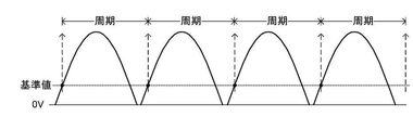
このデジタルデータを基準値クロス検出器130に入力すると、図3に示すように、基準値をクロスするポイントを検出することができる。基準値が波形と確実にクロスするように、基準値は、0Vと全波整流された波形の最大振幅値との間に設定するようにする。
When this digital data is input to the reference
基準値をクロスするポイントの間隔は、基準値の大きさによらず、変調前の信号の周期と等しくなる。このため、周期検出装置100は、振幅変調前の交流信号の周期を検出することができる。このとき、ローパスフィルタ120の出力が、ゼロ期間を有している波形であっても、0Vよりも大きい値を基準値に設定することで容易に変調前の交流信号の周期を検出することができる。
The interval between points that cross the reference value is equal to the period of the signal before modulation, regardless of the magnitude of the reference value. Therefore, the
以上説明したいように、本実施形態の周期検出装置100によれば、振幅変調された交流信号の周期を検出することができる。
As described above, according to the
10…測定装置
11…AD変換器
12…演算回路
100…周期検出装置
110…整流回路
120…ローパスフィルタ
130…基準値クロス検出器
10 ...
Claims (3)
前記整流回路の出力信号を濾波するローパスフィルタと、
前記ローパスフィルタの出力信号があらかじめ設定された基準値をクロスするポイントを検出する基準値クロス検出器と、
を備え、前記信号波の周期を検出することを特徴とする周期検出装置。 A rectifier circuit that performs full-wave rectification by inputting digital data of an AC signal obtained by amplitude-modulating a carrier wave with a signal wave.
A low-pass filter that filters the output signal of the rectifier circuit,
A reference value cross detector that detects a point at which the output signal of the low-pass filter crosses a preset reference value, and
A periodic detection device comprising the above and detecting the period of the signal wave.
検出されたポイントの間隔を前記信号波の周期として出力することを特徴とする請求項1に記載の周期検出装置。 The reference value cross detector is
The cycle detection device according to claim 1, wherein the interval between the detected points is output as the cycle of the signal wave.
前記整流された信号を、ローパスフィルタを用いて濾波するステップと、
前記ローパスフィルタの出力信号があらかじめ設定された基準値をクロスするポイントを検出するステップと、
を含むことを特徴とする前記信号波の周期検出方法。 A rectification step that performs full-wave rectification by inputting digital data of an AC signal obtained by amplitude-modulating a carrier wave with a signal wave.
The step of filtering the rectified signal using a low-pass filter and
A step of detecting a point at which the output signal of the low-pass filter crosses a preset reference value, and
The method for detecting the period of a signal wave, which comprises.
Priority Applications (1)
| Application Number | Priority Date | Filing Date | Title |
|---|---|---|---|
| JP2016184557A JP6899205B2 (en) | 2016-09-21 | 2016-09-21 | Period detection device and period detection method |
Applications Claiming Priority (1)
| Application Number | Priority Date | Filing Date | Title |
|---|---|---|---|
| JP2016184557A JP6899205B2 (en) | 2016-09-21 | 2016-09-21 | Period detection device and period detection method |
Publications (2)
| Publication Number | Publication Date |
|---|---|
| JP2018050190A JP2018050190A (en) | 2018-03-29 |
| JP6899205B2 true JP6899205B2 (en) | 2021-07-07 |
Family
ID=61767792
Family Applications (1)
| Application Number | Title | Priority Date | Filing Date |
|---|---|---|---|
| JP2016184557A Active JP6899205B2 (en) | 2016-09-21 | 2016-09-21 | Period detection device and period detection method |
Country Status (1)
| Country | Link |
|---|---|
| JP (1) | JP6899205B2 (en) |
Family Cites Families (15)
| Publication number | Priority date | Publication date | Assignee | Title |
|---|---|---|---|---|
| US4306567A (en) * | 1977-12-22 | 1981-12-22 | Krasner Jerome L | Detection and monitoring device |
| JPS62128646A (en) * | 1985-11-29 | 1987-06-10 | Nec Corp | Tone detecting circuit |
| JP2628690B2 (en) * | 1987-08-04 | 1997-07-09 | コーリン電子株式会社 | Respiratory rate monitor |
| JPH01274557A (en) * | 1988-04-27 | 1989-11-02 | Nec Corp | Tone detection circuit |
| JPH0732408B2 (en) * | 1989-06-14 | 1995-04-10 | 日本電気株式会社 | Burst detector |
| JP2570538B2 (en) * | 1991-12-20 | 1997-01-08 | 日本電気株式会社 | Signal detection system and burst demodulator |
| JP3402115B2 (en) * | 1997-04-04 | 2003-04-28 | 三菱電機株式会社 | Tone signal detector |
| JPH1198266A (en) * | 1997-09-19 | 1999-04-09 | Mitsubishi Electric Corp | Tone signal detector |
| JP2002252936A (en) * | 2001-02-23 | 2002-09-06 | Fuji Electric Co Ltd | Service interruption detecting circuit for uninterruptible power supply |
| JP5389393B2 (en) * | 2008-08-08 | 2014-01-15 | キヤノンファインテック株式会社 | Image forming apparatus and zero-cross detection control method |
| JP2011251058A (en) * | 2010-06-03 | 2011-12-15 | Panasonic Corp | Method and apparatus of measuring auditory steady-state response |
| WO2011155066A1 (en) * | 2010-06-11 | 2011-12-15 | 富士通株式会社 | Information recording device, information processing device, method for controlling disk device, and program for controlling disk device |
| JP2016540479A (en) * | 2013-11-27 | 2016-12-22 | モーメンタム ダイナミックス コーポレーション | Wireless transmission of line frequency and line voltage AC |
| JP5741736B1 (en) * | 2014-03-07 | 2015-07-01 | 株式会社豊田自動織機 | Periodic transition voltage period and phase detection apparatus and method |
| EP3160579B1 (en) * | 2014-06-25 | 2018-08-22 | Med-El Elektromedizinische Geraete GmbH | Prefitting evaluation of cochlear implant patients |
-
2016
- 2016-09-21 JP JP2016184557A patent/JP6899205B2/en active Active
Also Published As
| Publication number | Publication date |
|---|---|
| JP2018050190A (en) | 2018-03-29 |
Similar Documents
| Publication | Publication Date | Title |
|---|---|---|
| JP2015527005A5 (en) | ||
| US9194688B2 (en) | Inductive proximity sensor | |
| JP2016502110A5 (en) | ||
| KR20170016813A (en) | Fingerprint detection device and method | |
| US20110295530A1 (en) | Fault diagnosis device for amplitude modulation device | |
| WO2013155844A1 (en) | Three-phase ac phase-sequence detection method and device | |
| EP1602898A2 (en) | High resolution hall effect position sensor with a high immunity against electromagnetic noise | |
| JP2009171051A (en) | Synchronous clock generating circuit, analog-digital angle converter with synchronous clock generating circuit, and angle detection apparatus | |
| CN107505497B (en) | Time domain measurement method for peak value and peak value of signal of passive magnetoelectric rotation speed sensor | |
| JP3460587B2 (en) | Abnormality detector that detects abnormality of the rotation angle detector | |
| JP2013252040A (en) | Leakage diagnostic device of noncontact power supply system | |
| JP6035128B2 (en) | Method and apparatus for detecting an envelope | |
| JP6899205B2 (en) | Period detection device and period detection method | |
| KR101264039B1 (en) | Power quality monitoring apparatus and method thereof | |
| JP6769961B2 (en) | AM demodulation | |
| JP2005024493A (en) | Abnormality detector for resolver | |
| Banerjee et al. | A novel FPGA-based LVDT signal conditioner | |
| RU167006U1 (en) | AC VOLTAGE TRANSMITTER | |
| JP2015141031A (en) | Rotation angle detection device and method of detecting fault of rotation angle detection device | |
| US10110246B1 (en) | Δ-Σ methods for frequency deviation measurement of know nominal frequency value | |
| JP2008293460A (en) | Loop coil type vehicle detector | |
| JP2014215114A (en) | Pulse signal output circuit | |
| RU2644612C1 (en) | Measuring transducer of variable voltage into constant one | |
| JP2005214932A5 (en) | ||
| JP5352796B2 (en) | Rectification smoothing circuit and displacement detection device using the same |
Legal Events
| Date | Code | Title | Description |
|---|---|---|---|
| A621 | Written request for application examination |
Free format text: JAPANESE INTERMEDIATE CODE: A621 Effective date: 20190417 |
|
| A131 | Notification of reasons for refusal |
Free format text: JAPANESE INTERMEDIATE CODE: A131 Effective date: 20200416 |
|
| A521 | Written amendment |
Free format text: JAPANESE INTERMEDIATE CODE: A523 Effective date: 20200528 |
|
| A131 | Notification of reasons for refusal |
Free format text: JAPANESE INTERMEDIATE CODE: A131 Effective date: 20201102 |
|
| A521 | Written amendment |
Free format text: JAPANESE INTERMEDIATE CODE: A523 Effective date: 20201215 |
|
| TRDD | Decision of grant or rejection written | ||
| A01 | Written decision to grant a patent or to grant a registration (utility model) |
Free format text: JAPANESE INTERMEDIATE CODE: A01 Effective date: 20210603 |
|
| A61 | First payment of annual fees (during grant procedure) |
Free format text: JAPANESE INTERMEDIATE CODE: A61 Effective date: 20210614 |
|
| R150 | Certificate of patent or registration of utility model |
Ref document number: 6899205 Country of ref document: JP Free format text: JAPANESE INTERMEDIATE CODE: R150 |