JP6896837B2 - Load measurement system and load analysis method - Google Patents

Load measurement system and load analysis method Download PDF

Info

Publication number
JP6896837B2
JP6896837B2 JP2019500989A JP2019500989A JP6896837B2 JP 6896837 B2 JP6896837 B2 JP 6896837B2 JP 2019500989 A JP2019500989 A JP 2019500989A JP 2019500989 A JP2019500989 A JP 2019500989A JP 6896837 B2 JP6896837 B2 JP 6896837B2
Authority
JP
Japan
Prior art keywords
load
mounting
data
mounting machine
measurement
Prior art date
Legal status (The legal status is an assumption and is not a legal conclusion. Google has not performed a legal analysis and makes no representation as to the accuracy of the status listed.)
Active
Application number
JP2019500989A
Other languages
Japanese (ja)
Other versions
JPWO2018154761A1 (en
Inventor
浩二 河口
浩二 河口
康平 杉原
康平 杉原
秀範 丹羽
秀範 丹羽
光孝 畔▲柳▼
光孝 畔▲柳▼
Current Assignee (The listed assignees may be inaccurate. Google has not performed a legal analysis and makes no representation or warranty as to the accuracy of the list.)
Individual
Original Assignee
Individual
Priority date (The priority date is an assumption and is not a legal conclusion. Google has not performed a legal analysis and makes no representation as to the accuracy of the date listed.)
Filing date
Publication date
Application filed by Individual filed Critical Individual
Publication of JPWO2018154761A1 publication Critical patent/JPWO2018154761A1/en
Priority to JP2021096492A priority Critical patent/JP7236500B2/en
Application granted granted Critical
Publication of JP6896837B2 publication Critical patent/JP6896837B2/en
Active legal-status Critical Current
Anticipated expiration legal-status Critical

Links

Images

Classifications

    • HELECTRICITY
    • H05ELECTRIC TECHNIQUES NOT OTHERWISE PROVIDED FOR
    • H05KPRINTED CIRCUITS; CASINGS OR CONSTRUCTIONAL DETAILS OF ELECTRIC APPARATUS; MANUFACTURE OF ASSEMBLAGES OF ELECTRICAL COMPONENTS
    • H05K13/00Apparatus or processes specially adapted for manufacturing or adjusting assemblages of electric components
    • H05K13/04Mounting of components, e.g. of leadless components

Description

本発明は、実装機の装着ヘッドが付与する荷重を計測する荷重計測システム及び荷重の分析方法に関するものである。 The present invention relates to a load measuring system for measuring a load applied to a mounting head of a mounting machine and a load analysis method .

電子部品(以下、単に「部品」という場合がある)を回路基板(以下、単に「基板」という場合がある)に実装する実装機では、基板の破損や電気的な接続の不具合などを抑制するため、部品を基板に対して押圧する荷重を適正な値に設定することが要求される。また、近年の部品の高集積化、小型化、薄型化等によって、部品を押圧する荷重を、より高精度に管理することが望まれている。これに対し、部品を基板に装着する際に、装着ヘッドの吸着ノズルによって部品を押圧する荷重を計測する荷重計測装置がある(例えば、特許文献1など)。 A mounting machine that mounts electronic components (hereinafter, may be simply referred to as "components") on a circuit board (hereinafter, may be simply referred to as "board") suppresses damage to the board and defects in electrical connection. Therefore, it is required to set an appropriate value for the load that presses the component against the substrate. Further, it is desired to manage the load pressing the parts with higher accuracy due to the recent increase in integration, miniaturization, thinning, etc. of the parts. On the other hand, there is a load measuring device that measures the load of pressing the component by the suction nozzle of the mounting head when the component is mounted on the substrate (for example, Patent Document 1).

特許文献1に開示される荷重計測装置(文献では、「実装荷重測定装置」)は、吸着ノズルによって付与される荷重を検出するロードセルと、ロードセルの検出結果に基づいて荷重を計測するデータロガーとを備えている。荷重計測装置は、実装機における基板を搬送する搬送路の幅に合わせて形成されている。そして、荷重計測装置は、基板と同様に搬送路上を搬送させられ、所定の実装位置で荷重を計測する。 The load measuring device disclosed in Patent Document 1 (in the document, "mounted load measuring device") includes a load cell that detects the load applied by the suction nozzle and a data logger that measures the load based on the detection result of the load cell. It has. The load measuring device is formed according to the width of the transport path for transporting the substrate in the mounting machine. Then, the load measuring device is conveyed on the transport path in the same manner as the substrate, and measures the load at a predetermined mounting position.

特開2015−220294号公報Japanese Unexamined Patent Publication No. 2015-20294

上記した荷重計測装置は、実装機から搬出された後に回収され、パーソナルコンピュータと接続されて計測データを読み出される。しかしながら、上記した特許文献1には、パーソナルコンピュータが、荷重計測装置の計測データをどのような基準やデータに基づいて分析するのかについて具体的に記載されていない。このため、計測データを分析する処理について改善の余地があった。 The load measuring device described above is taken out from the mounting machine, then collected, connected to a personal computer, and the measured data is read out. However, the above-mentioned Patent Document 1 does not specifically describe what kind of standard or data the personal computer analyzes the measurement data of the load measuring device based on. Therefore, there is room for improvement in the process of analyzing the measurement data.

本発明は、そのような実情に鑑みてなされたものであり、本発明の課題は、荷重の計測データを実装機の計測条件に基づいて分析できる荷重計測システム及び荷重の分析方法を提供することである。 The present invention has been made in view of such circumstances, and an object of the present invention is to provide a load measurement system and a load analysis method capable of analyzing load measurement data based on the measurement conditions of a mounting machine. Is.

上記課題を解決するために、本明細書は、基板に対して部品を装着する装着ヘッドを有する実装機に配置され、装着の際に前記装着ヘッドが前記部品に付与する荷重を計測する荷重計測装置と、分析装置と、を備え、前記装着ヘッドは、前記部品を吸着して保持する複数の吸着ノズルを備え、前記荷重計測装置は、所定の順番で前記複数の吸着ノズルの各々から1つの吸着ノズルについて複数回荷重を付与され、その順番に荷重を計測した結果である計測データを保存し、前記分析装置は、荷重を計測する際の前記実装機の条件であり、計測を実行した吸着ノズルの順番を含む条件データを取得する第一取得処理と、前記計測データを、前記荷重計測装置から取得する第二取得処理と、前記第一取得処理で取得した前記条件データに基づいて、前記第二取得処理で取得した前記計測データを分析し、複数の前記計測データを前記複数の吸着ノズル毎に集計して前記複数の吸着ノズル毎の集計結果を表示する分析処理と、を実行する、荷重計測システムを開示する。
また、本明細書は、基板に対して部品を装着する装着ヘッドを有する実装機に配置され、装着の際に前記装着ヘッドが前記部品に付与する荷重を計測する荷重計測装置と、分析装置と、を備え、前記分析装置は、荷重を計測する際の前記実装機の条件であり、許容する荷重値の範囲を示す荷重幅として基準とする荷重値に対する差分の割合により定められた荷重幅を含む条件データを取得する第一取得処理と、荷重を計測した結果である計測データを、前記荷重計測装置から取得する第二取得処理と、前記第一取得処理で取得した前記条件データに基づいて、前記第二取得処理で取得した前記計測データの荷重の良否を分析する分析処理と、を実行する、荷重計測システムを開示する。
尚、本開示の内容は、荷重計測システムとしての実施に限らず、種々の形態により実施することができる。例えば、本開示の内容は、荷重の分析方法として実施しても有益である。
In order to solve the above problems, the present specification is arranged in a mounting machine having a mounting head for mounting a component on a board, and a load measurement for measuring a load applied to the component by the mounting head at the time of mounting. The mounting head comprises an apparatus and an analyzer, the mounting head includes a plurality of suction nozzles for sucking and holding the component, and the load measuring device is one from each of the plurality of suction nozzles in a predetermined order. granted multiple load for suction nozzle, and save the measurement data which is the result of a load measured in that order, the analyzer, Ri condition der of said mounting device when measuring the load was performed to measure a first acquisition processing for acquiring condition data including the order of the suction nozzle, the measurement data, a second acquisition processing for acquiring from said load measuring device, based on the condition data acquired by the first acquisition processing, An analysis process is executed in which the measurement data acquired in the second acquisition process is analyzed , a plurality of the measurement data are aggregated for each of the plurality of suction nozzles, and the aggregation result for each of the plurality of suction nozzles is displayed. , Disclose the load measurement system.
Further, the present specification includes a load measuring device and an analyzer which are arranged in a mounting machine having a mounting head for mounting a component on a substrate and measure a load applied to the component by the mounting head at the time of mounting. The analyzer is a condition of the mounting machine when measuring a load, and has a load width determined by a ratio of a difference to a reference load value as a load width indicating a range of allowable load values. Based on the first acquisition process for acquiring the included condition data, the second acquisition process for acquiring the measurement data as a result of measuring the load from the load measuring device, and the condition data acquired in the first acquisition process. Discloses a load measurement system that executes an analysis process for analyzing the quality of the load of the measurement data acquired in the second acquisition process.
The content of the present disclosure is not limited to the implementation as a load measurement system, and can be implemented in various forms. For example, the contents of the present disclosure may be useful as a load analysis method.

本開示によれば、分析装置は、荷重の計測時における実装機の条件データを取得する。また、分析装置は、荷重計測装置から荷重の計測データを取得する。分析装置は、荷重の計測時における実装機の条件に基づいて計測データを分析する。これにより、計測した荷重の分析を、実装機の計測時の条件に基づいて分析することが可能となる。 According to the present disclosure, the analyzer acquires condition data of the mounting machine at the time of load measurement. In addition, the analyzer acquires load measurement data from the load measuring device. The analyzer analyzes the measurement data based on the conditions of the mounting machine at the time of load measurement. This makes it possible to analyze the measured load based on the conditions at the time of measurement of the mounting machine.

対基板作業システムの構成を示す模式図である。It is a schematic diagram which shows the structure of the board-to-board work system. 実装機の平面図である。It is a top view of the mounting machine. 実装機の作業位置に基板を配置した状態における断面図である。It is sectional drawing in the state which the substrate is arranged at the working position of a mounting machine. 荷重計測装置の平面図である。It is a top view of the load measuring device. 実装機の作業位置に荷重計測装置を配置した状態における断面図である。It is sectional drawing in the state which the load measuring apparatus is arranged at the working position of a mounting machine. 荷重計測装置のブロック図である。It is a block diagram of a load measuring device. 荷重計測用の制御データの生成から、計測データの分析までの一連の処理手順を示すフローチャートである。It is a flowchart which shows a series of processing procedures from the generation of control data for load measurement to the analysis of measurement data. 荷重計測処理を示すフローチャートである。It is a flowchart which shows the load measurement process. 分析コンピュータに表示される分析結果の一例を示す図である。It is a figure which shows an example of the analysis result displayed on the analysis computer. 条件データを選択する表示画面の一例を示す図である。It is a figure which shows an example of the display screen which selects the condition data. 別例の荷重計測装置の平面図である。It is a top view of the load measuring apparatus of another example.

以下、本発明の荷重計測システムの実施形態の一例として対基板作業システム10について、図を参照しつつ詳しく説明する。 Hereinafter, as an example of the embodiment of the load measurement system of the present invention, the substrate working system 10 will be described in detail with reference to the drawings.

(対基板作業システムの構成)
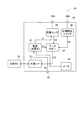
図1は、本実施形態の実装機11を備える対基板作業システム10の概略構成を示している。対基板作業システム10は、回路基板(以下、「基板」という)CBに部品を実装するシステムである。対基板作業システム10は、1つの部品実装ライン12と、生産管理コンピュータ18と、分析コンピュータ19と、後述する荷重計測装置81とを備えている。基板CBは、図1における左側から右側に向かって部品実装ライン12を搬送され、各種装置によって作業が行われる。部品実装ライン12は、複数(本実施形態では4台)の実装機11と、半田印刷機13と、検査装置14と、リフロー装置15と、基板ハンドリング装置17とを接続して構成されている。各装置等は、隣接した状態で1列に配設され、生産管理コンピュータ18によって統括的に制御される。なお、以下の説明では、各装置等の並ぶ方向をX軸方向、その方向に直交し基板CBの平面と平行な方向をY軸方向と称して説明する。
(Configuration of board-to-board work system)
FIG. 1 shows a schematic configuration of a board-to-board work system 10 including the mounting machine 11 of the present embodiment. The board-to-board work system 10 is a system in which components are mounted on a circuit board (hereinafter referred to as “board”) CB. The board-to-board work system 10 includes one component mounting line 12, a production control computer 18, an analysis computer 19, and a load measuring device 81 described later. The substrate CB is conveyed along the component mounting line 12 from the left side to the right side in FIG. 1, and work is performed by various devices. The component mounting line 12 is configured by connecting a plurality of (four in this embodiment) mounting machines 11, a solder printing machine 13, an inspection device 14, a reflow device 15, and a board handling device 17. .. The devices and the like are arranged in a row adjacent to each other and are collectively controlled by the production control computer 18. In the following description, the direction in which the devices are lined up is referred to as the X-axis direction, and the direction orthogonal to the X-axis direction and parallel to the plane of the substrate CB is referred to as the Y-axis direction.

半田印刷機13は、基板CBに対して半田ペーストを印刷する。実装機11は、半田ペーストを印刷された基板CBに部品を装着する。なお、実装機11の詳細については、後述する。検査装置14は、基板CBに装着した部品の状態や異物の有無などを検査する。リフロー装置15は、ペースト状の半田を加熱して再溶融した後に冷却固化して、部品の装着を完結させる。基板ハンドリング装置17は、実装機11等に対して部品実装ライン12における上流及び下流に設けられている。基板ハンドリング装置17の各々は、基板CBを次の装置に搬送したり、待機させたり、あるいは上下を反転させたりする。 The solder printing machine 13 prints the solder paste on the substrate CB. The mounting machine 11 mounts the components on the substrate CB on which the solder paste is printed. The details of the mounting machine 11 will be described later. The inspection device 14 inspects the state of the parts mounted on the substrate CB, the presence or absence of foreign matter, and the like. The reflow device 15 heats the paste-like solder, remelts it, and then cools and solidifies it to complete the mounting of the parts. The board handling device 17 is provided upstream and downstream of the component mounting line 12 with respect to the mounting machine 11 and the like. Each of the board handling devices 17 transports the board CB to the next device, makes it stand by, or turns it upside down.

生産管理コンピュータ18は、CPU、RAM等を備えたコンピュータを主体として構成されている。生産管理コンピュータ18は、実装機11等とネットワークNW1を介して接続されている。生産管理コンピュータ18は、実装機11等の動作を制御するための制御データD1を、実装機11等に送信する。実装機11等は、生産管理コンピュータ18から受信した制御データD1に基づいて装着作業等を実行する。生産管理コンピュータ18には、複数の制御データD1や、制御データD1を生成するための各種データ(後述する目標荷重値や荷重幅など)が保存されている。 The production control computer 18 is mainly composed of a computer equipped with a CPU, RAM, and the like. The production control computer 18 is connected to the mounting machine 11 and the like via the network NW1. The production control computer 18 transmits the control data D1 for controlling the operation of the mounting machine 11 and the like to the mounting machine 11 and the like. The mounting machine 11 and the like execute mounting work and the like based on the control data D1 received from the production control computer 18. The production control computer 18 stores a plurality of control data D1 and various data for generating the control data D1 (target load value, load width, etc., which will be described later).

生産管理コンピュータ18には、ネットワークNW2を介して分析コンピュータ19が接続されている。分析コンピュータ19は、CPU、RAM等を備えたコンピュータを主体として構成され、操作部19Aと、表示部19Bとを有している。操作部19Aは、例えば、キーボードやマウス等の入力デバイスである。表示部19Bは、例えば、各種情報を表示するディスプレイである。 The analysis computer 19 is connected to the production control computer 18 via the network NW2. The analysis computer 19 is mainly composed of a computer equipped with a CPU, RAM, and the like, and has an operation unit 19A and a display unit 19B. The operation unit 19A is, for example, an input device such as a keyboard or a mouse. The display unit 19B is, for example, a display that displays various types of information.

ユーザは、分析コンピュータ19の操作部19Aを操作することで、例えば、ネットワークNW2を介して生産管理コンピュータ18に保存された制御データD1の内容を変更することができる。また、ユーザは、操作部19Aを操作することで、生産管理コンピュータ18から特定の実装機11等に、制御データD1を送信することができる。これにより、ユーザは、分析コンピュータ19の操作部19Aを操作することで、荷重を計測するための装着作業を行う制御データD1の生成や、生成した制御データD1を計測対象の実装機11へ送信する処理を行うことができる。 By operating the operation unit 19A of the analysis computer 19, the user can change the content of the control data D1 stored in the production control computer 18 via the network NW2, for example. Further, the user can transmit the control data D1 from the production control computer 18 to the specific mounting machine 11 or the like by operating the operation unit 19A. As a result, the user operates the operation unit 19A of the analysis computer 19 to generate control data D1 for performing mounting work for measuring the load, and transmits the generated control data D1 to the mounting machine 11 to be measured. Can be processed.

また、本実施形態の分析コンピュータ19は、後述する荷重計測装置81で荷重を計測した実装機11から生産管理コンピュータ18を介して、荷重を計測する際の条件である条件データD2を取得する(第一取得処理)。即ち、条件データD2は、実装機11からネットワークNW1、生産管理コンピュータ18、及びネットワークNW2を介して分析コンピュータ19へ転送される。 Further, the analysis computer 19 of the present embodiment acquires condition data D2, which is a condition for measuring the load, from the mounting machine 11 whose load is measured by the load measuring device 81 described later via the production control computer 18 ( First acquisition process). That is, the condition data D2 is transferred from the mounting machine 11 to the analysis computer 19 via the network NW1, the production control computer 18, and the network NW2.

また、本実施形態の分析コンピュータ19は、荷重計測装置81と接続するための外部インターフェース19Cを有している。外部インターフェース19Cは、荷重計測装置81の外部インターフェース101(図6参照)と接続するためのインターフェースである。外部インターフェース19C,101としては、特に規格等を限定されないが、例えば、USB(Universal Serial Bus)規格に準拠したインターフェースを採用することができる。なお、分析コンピュータ19は、荷重計測装置81と無線通信可能な構成でもよい。 Further, the analysis computer 19 of the present embodiment has an external interface 19C for connecting to the load measuring device 81. The external interface 19C is an interface for connecting to the external interface 101 (see FIG. 6) of the load measuring device 81. The external interfaces 19C and 101 are not particularly limited in standard and the like, but for example, an interface compliant with the USB (Universal Serial Bus) standard can be adopted. The analysis computer 19 may be configured to be capable of wireless communication with the load measuring device 81.

分析コンピュータ19は、外部インターフェース19Cを介して、荷重を計測した計測データD3を荷重計測装置81から取得する(第二取得処理)。分析コンピュータ19は、条件データD2に基づいて計測データD3を分析し、分析結果を表示部19Bに表示する。
なお、荷重計測装置81の詳細については後述する。
The analysis computer 19 acquires the measurement data D3 for which the load is measured from the load measuring device 81 via the external interface 19C (second acquisition process). The analysis computer 19 analyzes the measurement data D3 based on the condition data D2 and displays the analysis result on the display unit 19B.
The details of the load measuring device 81 will be described later.

(実装機の構成)
図2は、実装機11の平面図を示している。図2に示すように、実装機11は、搬送装置20、装着ヘッド移動装置(以下、「移動装置」と略す場合がある)22、装着ヘッド24、供給装置26を有している。
(Configuration of mounting machine)
FIG. 2 shows a plan view of the mounting machine 11. As shown in FIG. 2, the mounting machine 11 includes a transport device 20, a mounting head moving device (hereinafter, may be abbreviated as “moving device”) 22, a mounting head 24, and a supply device 26.

搬送装置20は、X軸方向に延びるコンベア31を有している。基板CBは、コンベア31によって支持され、X軸方向に搬送される。図3は、実装機11の作業位置を示しており、X軸方向に垂直な平面に沿って切断した断面図を示している。図3に示すように、コンベア31は、コンベアベルト33と、ストッパ35と、クランパ36とを有している。コンベアベルト33は、Y軸方向において所定の距離だけ離間した一組が設けられ、基板CBを上に載せた状態で周回し、基板CBを所定の作業位置(例えば、図2に示す位置)まで搬送する。クランパ36は、作業位置において基板CBを間に挟んでストッパ35と上下方向で対向する位置に設けられている。コンベア31は、コンベアベルト33を周回させて基板CBを作業位置まで搬送すると、クランパ36を上昇させる。基板CBは、クランパ36とストッパ35との間に挟み込まれ、作業位置において固定的に保持される。 The transport device 20 has a conveyor 31 extending in the X-axis direction. The substrate CB is supported by the conveyor 31 and conveyed in the X-axis direction. FIG. 3 shows the working position of the mounting machine 11, and shows a cross-sectional view cut along a plane perpendicular to the X-axis direction. As shown in FIG. 3, the conveyor 31 has a conveyor belt 33, a stopper 35, and a clamper 36. The conveyor belts 33 are provided with a set separated by a predetermined distance in the Y-axis direction, and orbit the conveyor belt CB with the substrate CB placed on the conveyor belt 33 to a predetermined working position (for example, the position shown in FIG. 2). Transport. The clamper 36 is provided at a position facing the stopper 35 in the vertical direction with the substrate CB sandwiched between them at the working position. When the conveyor 31 orbits the conveyor belt 33 and conveys the substrate CB to the working position, the clamper 36 is raised. The substrate CB is sandwiched between the clamper 36 and the stopper 35, and is fixedly held at the working position.

また、実装機11の作業位置には、駆動部41(例えば、エアシリンダ)によって昇降可能な昇降台43が設けられている。昇降台43の上には、昇降台43に対して取り替え可能なバックアップベース44が設けられている。バックアップベース44の上面には、複数のバックアップピン46が立設している。実装機11は、部品を装着する際に、駆動部41を駆動して昇降台43を上昇させ、ストッパ35及びクランパ36によって位置を保持された基板CBの下面にバックアップピン46を当接させる。これにより、バックアップピン46は、部品装着時に基板CBを撓まないように支持する。 Further, at the working position of the mounting machine 11, a lift 43 that can be raised and lowered by a drive unit 41 (for example, an air cylinder) is provided. A backup base 44 that can be replaced with respect to the lift 43 is provided on the lift 43. A plurality of backup pins 46 are erected on the upper surface of the backup base 44. When mounting the components, the mounting machine 11 drives the drive unit 41 to raise the lift 43, and brings the backup pin 46 into contact with the lower surface of the substrate CB whose position is held by the stopper 35 and the clamper 36. As a result, the backup pin 46 supports the substrate CB so as not to bend when the component is mounted.

また、図2に示すように、移動装置22は、X軸方向スライド機構50と、Y軸方向スライド機構52とを有している。X軸方向スライド機構50は、X軸方向に移動可能にベース54上に設けられたX軸スライダ56を有している。X軸スライダ56は、電磁モータ(図示省略)の駆動により、X軸方向の任意の位置に移動する。また、Y軸方向スライド機構52は、Y軸スライダ60を有している。Y軸スライダ60は、Y軸方向に移動可能にX軸スライダ56の側面に設けられている。Y軸スライダ60は、電磁モータ(図示省略)の駆動により、Y軸方向の任意の位置に移動する。装着ヘッド24は、Y軸スライダ60に取り付けられている。このような構造により、装着ヘッド24は、移動装置22によってベース54上の任意の位置に移動する。なお、装着ヘッド24は、Y軸スライダ60に着脱可能とされており、作業に応じたヘッドに交換可能とされている。 Further, as shown in FIG. 2, the moving device 22 has an X-axis direction slide mechanism 50 and a Y-axis direction slide mechanism 52. The X-axis direction slide mechanism 50 has an X-axis slider 56 provided on the base 54 so as to be movable in the X-axis direction. The X-axis slider 56 moves to an arbitrary position in the X-axis direction by driving an electromagnetic motor (not shown). Further, the Y-axis direction slide mechanism 52 has a Y-axis slider 60. The Y-axis slider 60 is provided on the side surface of the X-axis slider 56 so as to be movable in the Y-axis direction. The Y-axis slider 60 moves to an arbitrary position in the Y-axis direction by driving an electromagnetic motor (not shown). The mounting head 24 is mounted on the Y-axis slider 60. With such a structure, the mounting head 24 is moved to an arbitrary position on the base 54 by the moving device 22. The mounting head 24 is detachable from the Y-axis slider 60 and can be replaced with a head according to the work.

装着ヘッド24は、基板CBに対して部品を装着するものである。装着ヘッド24は、下面に設けられた複数(図2においては1つのみ図示)の吸着ノズル70を有している。各吸着ノズル70は、負圧エア,正圧エア通路を介して、正負圧供給装置(図示省略)に通じている。吸着ノズル70は、負圧によって部品を吸着保持し、保持した部品を正圧によって離脱する。また、装着ヘッド24は、吸着ノズル70を昇降させる昇降装置(図示省略)を有している。その昇降装置によって、装着ヘッド24は、部品を保持する吸着ノズル70の上下方向の位置を変更する。なお、吸着ノズル70は、装着ヘッド24に着脱可能とされており、保持対象の部品に応じた吸着ノズルや多の保持部材(チャックなど)に交換可能とされている。 The mounting head 24 mounts components on the substrate CB. The mounting head 24 has a plurality of suction nozzles 70 (only one is shown in FIG. 2) provided on the lower surface. Each suction nozzle 70 communicates with a positive / negative pressure supply device (not shown) via a negative pressure air and a positive pressure air passage. The suction nozzle 70 sucks and holds the component by negative pressure, and releases the held component by positive pressure. Further, the mounting head 24 has an elevating device (not shown) for elevating and lowering the suction nozzle 70. The lifting device causes the mounting head 24 to change the vertical position of the suction nozzle 70 that holds the component. The suction nozzle 70 is removable from the mounting head 24, and can be replaced with a suction nozzle or a large number of holding members (chuck or the like) according to the component to be held.

供給装置26は、フィーダ型の供給装置であり、複数のテープフィーダ72を有している。テープフィーダ72は、テープ化部品を巻回させた状態で収容している。テープ化部品は、部品をテーピング化したものである。テープフィーダ72は、送り装置(図示省略)によってテープ化部品を送り出し、部品を供給位置に供給する。 The feeder 26 is a feeder type feeder, and has a plurality of tape feeders 72. The tape feeder 72 houses the taped parts in a wound state. The taped part is a taped part. The tape feeder 72 feeds the taped parts by a feeding device (not shown) and supplies the parts to the supply position.

(実装機による装着作業)
実装機11は、上述した構成によって、基板CBに対する部品の装着作業を行う。より具体的には、実装機11は、上流側の基板ハンドリング装置17から搬入された基板CBを、搬送装置20によって作業位置まで搬送する。ストッパ35及びクランパ36は、作業位置において、基板CBを固定的に保持する。また、テープフィーダ72は、テープ化部品を送り出し、部品を供給位置に供給する。装着ヘッド24は、テープフィーダ72の供給位置の上方に移動し、吸着ノズル70によって部品を吸着保持する。装着ヘッド24は、作業位置に配置された基板CBの上方に移動し、保持している部品を基板CBに装着する。下流側の基板ハンドリング装置17は、実装機11による部品の装着作業が完了すると、下流側の他の装着に基板CBを搬送する。
(Mounting work by mounting machine)
The mounting machine 11 performs mounting work of parts on the substrate CB according to the above-described configuration. More specifically, the mounting machine 11 transports the substrate CB carried in from the substrate handling device 17 on the upstream side to the working position by the transport device 20. The stopper 35 and the clamper 36 fixedly hold the substrate CB at the working position. Further, the tape feeder 72 sends out the taped parts and supplies the parts to the supply position. The mounting head 24 moves above the supply position of the tape feeder 72, and the suction nozzle 70 sucks and holds the component. The mounting head 24 moves above the board CB arranged at the working position, and mounts the held component on the board CB. When the mounting work of the parts by the mounting machine 11 is completed, the board handling device 17 on the downstream side conveys the board CB to another mounting on the downstream side.

(荷重計測装置の構成)
次に、本実施形態の荷重計測装置81の構成について説明する。図4は、本実施形態の荷重計測装置81の平面図を示している。図5は、荷重計測装置81の断面図であり、荷重計測装置81を実装機11の作業位置に配置した状態を示している。即ち、図5は、図3に対応し、基板CBに替えて荷重計測装置81を配置した状態となっている。また、図6は、荷重計測装置81の電気的な構成を示している。
(Configuration of load measuring device)
Next, the configuration of the load measuring device 81 of the present embodiment will be described. FIG. 4 shows a plan view of the load measuring device 81 of the present embodiment. FIG. 5 is a cross-sectional view of the load measuring device 81, showing a state in which the load measuring device 81 is arranged at the working position of the mounting machine 11. That is, FIG. 5 corresponds to FIG. 3 and shows a state in which the load measuring device 81 is arranged in place of the substrate CB. Further, FIG. 6 shows the electrical configuration of the load measuring device 81.

なお、本実施形態の荷重計測装置81の構成は一例であり、荷重を計測可能な他の構成でもよい。また、図5では、バックアップベース44は、バックアップピン46を取り外した状態となっている。これにより、バックアップベース44とコンベア31との間には、より大きな空間を確保することが可能となる。また、以下の説明では、荷重計測装置81を搬送する際の方向(X軸方向及びY軸方向)を用いて、荷重計測装置81の各部材の位置等について説明する。 The configuration of the load measuring device 81 of the present embodiment is an example, and other configurations capable of measuring the load may be used. Further, in FIG. 5, the backup base 44 is in a state in which the backup pin 46 is removed. This makes it possible to secure a larger space between the backup base 44 and the conveyor 31. Further, in the following description, the positions of each member of the load measuring device 81 and the like will be described using the directions (X-axis direction and Y-axis direction) when the load measuring device 81 is conveyed.

図4及び図5に示すように、荷重計測装置81は、筐体83と、筐体83の上面に取り付けられた被挟持板85,86とを有している。筐体83は、上方から視た場合に略正方形状をなしている。筐体83は、X軸方向及びY軸方向に伸び、上下方向に所定の厚みをもった厚い板状をなしている。筐体83の上下方向の厚みL2(図5参照)は、例えば、50mmである。なお、荷重計測装置81を薄型に構成した場合は、バックアップピン46をバックアップベース44に取り付けたまま、荷重計測装置81をコンベア31で搬送してもよい。 As shown in FIGS. 4 and 5, the load measuring device 81 has a housing 83 and holding plates 85 and 86 attached to the upper surface of the housing 83. The housing 83 has a substantially square shape when viewed from above. The housing 83 extends in the X-axis direction and the Y-axis direction, and has a thick plate shape having a predetermined thickness in the vertical direction. The vertical thickness L2 (see FIG. 5) of the housing 83 is, for example, 50 mm. When the load measuring device 81 is made thin, the load measuring device 81 may be conveyed by the conveyor 31 with the backup pin 46 attached to the backup base 44.

被挟持板85,86は、筐体83の上面83AにおけるY軸方向の両端のそれぞれに設けられている。被挟持板85,86は、Y軸方向の幅を略同一としながらX軸方向に延設された板状をなしている。被挟持板85,86の上下方向の厚みL3は、図3に示す基板CBの厚みL1と同一(例えば、2mm)となっている。被挟持板85,86は、筐体83のY軸方向における側縁部から外側に向かって、且つ、上面83Aの平面に沿って延設されている。コンベアベルト33は、この被挟持板85,86のY軸方向の外側に突出した部分の下面を支持している。また、被挟持板85,86の各々は、複数(本実施形態では、5個)のネジ88によって筐体83に対して固定されている。コンベア31は、被挟持板85,86の筐体83からY軸方向の外側に突出した部分を、コンベアベルト33に乗せた状態で荷重計測装置81を搬送する。荷重計測装置81のY軸方向に沿った幅W2は、基板CBの基板幅W1(図3参照)と略同一となっている。 The sandwiched plates 85 and 86 are provided at both ends in the Y-axis direction on the upper surface 83A of the housing 83. The sandwiched plates 85 and 86 have a plate shape extending in the X-axis direction while having substantially the same width in the Y-axis direction. The vertical thickness L3 of the sandwiched plates 85 and 86 is the same as the thickness L1 of the substrate CB shown in FIG. 3 (for example, 2 mm). The sandwiched plates 85 and 86 extend outward from the side edges of the housing 83 in the Y-axis direction and along the plane of the upper surface 83A. The conveyor belt 33 supports the lower surface of the portion of the sandwiched plates 85, 86 that protrudes outward in the Y-axis direction. Further, each of the sandwiched plates 85 and 86 is fixed to the housing 83 by a plurality of (five in this embodiment) screws 88. The conveyor 31 conveys the load measuring device 81 with the portions of the sandwiched plates 85 and 86 protruding outward in the Y-axis direction from the housings 83 on the conveyor belt 33. The width W2 of the load measuring device 81 along the Y-axis direction is substantially the same as the substrate width W1 of the substrate CB (see FIG. 3).

図6に示すように、荷重計測装置81は、電源91と、電源スイッチ93と、残量メータ94と、荷重センサ95と、データロガー97と、計測開始スイッチ99と、外部インターフェース101等を有している。電源91は、例えば、充電式のバッテリーであり、荷重センサ95及びデータロガー97へ直流の電圧V1を供給する。 As shown in FIG. 6, the load measuring device 81 includes a power supply 91, a power supply switch 93, a remaining amount meter 94, a load sensor 95, a data logger 97, a measurement start switch 99, an external interface 101, and the like. doing. The power supply 91 is, for example, a rechargeable battery, and supplies a DC voltage V1 to the load sensor 95 and the data logger 97.

電源スイッチ93は、電源91から荷重センサ95等への電圧V1の供給の開始、又は停止を切り替えるスイッチである。電源スイッチ93は、筐体83の底面83E(図5参照)に取り付けられている。電源スイッチ93は、例えば、スライドスイッチやタクトスイッチ(登録商標)等であり、ユーザからの操作に応じたON/OFF信号S1を電源91へ出力する。電源91は、電源スイッチ93からのON/OFF信号S1に応じて、荷重センサ95等への電圧V1の供給を開始、又は停止する。残量メータ94は、筐体83の底面83Eに取り付けられている。残量メータ94は、電源91と接続されており、電源91のバッテリーの残量を表示する。 The power switch 93 is a switch for switching between starting and stopping the supply of the voltage V1 from the power supply 91 to the load sensor 95 and the like. The power switch 93 is attached to the bottom surface 83E (see FIG. 5) of the housing 83. The power switch 93 is, for example, a slide switch, a tact switch (registered trademark), or the like, and outputs an ON / OFF signal S1 according to an operation from the user to the power supply 91. The power supply 91 starts or stops supplying the voltage V1 to the load sensor 95 or the like in response to the ON / OFF signal S1 from the power switch 93. The remaining amount meter 94 is attached to the bottom surface 83E of the housing 83. The remaining amount meter 94 is connected to the power supply 91 and displays the remaining amount of the battery of the power supply 91.

荷重センサ95は、装着ヘッド24の吸着ノズル70によって押圧される荷重(部品を押圧する力など)を検出するセンサである。荷重センサ95は、例えば、水晶圧電式の荷重センサであり、上下方向の荷重のみを検出する1軸センサとして構成されている。なお、荷重センサ95は、歪みゲージ式等の他の方式の荷重センサでもよい。歪みゲージ式の荷重センサは、応答性の観点から水晶圧電式のものに比べて衝撃荷重(動的な力)を精度よく検出できない可能性がある。このため、荷重センサ95としては、水晶圧電式の荷重センサが好ましい。また、荷重センサ95は、複数の方向の荷重を検出可能な複数軸の荷重センサでもよい。 The load sensor 95 is a sensor that detects a load (such as a force that presses a component) pressed by the suction nozzle 70 of the mounting head 24. The load sensor 95 is, for example, a crystal piezoelectric type load sensor, and is configured as a uniaxial sensor that detects only a load in the vertical direction. The load sensor 95 may be a load sensor of another type such as a strain gauge type. From the viewpoint of responsiveness, the strain gauge type load sensor may not be able to detect the impact load (dynamic force) more accurately than the quartz piezoelectric type. Therefore, as the load sensor 95, a crystal piezoelectric type load sensor is preferable. Further, the load sensor 95 may be a load sensor having a plurality of axes capable of detecting loads in a plurality of directions.

荷重センサ95は、筐体83の上面83Aに取り付けられた荷重入力部95Aを有する。図4に示すように、上面83Aには、被挟持板86に近接する位置に計測板83Cが設けられている。計測板83Cには、上下方向に貫通する貫通孔83Dが形成されている。荷重入力部95Aは、略円柱形状をなし、貫通孔83D内を上下方向に挿通されている。 The load sensor 95 has a load input unit 95A attached to the upper surface 83A of the housing 83. As shown in FIG. 4, the upper surface 83A is provided with the measuring plate 83C at a position close to the sandwiched plate 86. The measuring plate 83C is formed with a through hole 83D penetrating in the vertical direction. The load input unit 95A has a substantially cylindrical shape and is inserted in the through hole 83D in the vertical direction.

ここで、ユーザは、例えば、荷重の計測を行う際、テープフィーダ72に部品をセットしない。そして、実装機11は、制御データD1に基づいて装着ヘッド24を駆動し、部品を吸着保持していない吸着ノズル70によって荷重入力部95Aを押圧する。荷重センサ95は、吸着ノズル70によって荷重入力部95Aを下方へ押下されると、その荷重で水晶圧電素子(図示略)の内部に圧縮応力を生じさせ、応力の大きさに応じたアナログの検出電圧V2を出力する。荷重センサ95は、検出電圧V2をデータロガー97に出力する。なお、荷重センサ95は、検出電圧V2を増幅するアンプ等を備えてもよい。 Here, the user does not set the component on the tape feeder 72, for example, when measuring the load. Then, the mounting machine 11 drives the mounting head 24 based on the control data D1 and presses the load input unit 95A by the suction nozzle 70 that does not suck and hold the parts. When the load input unit 95A is pushed downward by the suction nozzle 70, the load sensor 95 generates compressive stress inside the quartz piezoelectric element (not shown) by the load, and detects analog according to the magnitude of the stress. The voltage V2 is output. The load sensor 95 outputs the detection voltage V2 to the data logger 97. The load sensor 95 may include an amplifier or the like that amplifies the detection voltage V2.

本実施形態の荷重センサ95は、例えば、静荷重と動荷重とを計測可能となっている。ここでいう静荷重とは、例えば、吸着ノズル70から荷重センサ95(実装時には部品や基板CB)に加わる荷重のうち、時間の経過に対して変化せず一定の値となる荷重である。また、動荷重とは、吸着ノズル70から荷重センサ95に加わる荷重のうち、時間の経過に対して変化する荷重である。具体的には、動荷重は、例えば、吸着ノズル70を荷重入力部95Aに接触(衝突)させた際に発生する衝突荷重である。静荷重は、例えば、接触後に吸着ノズル70によって荷重入力部95Aを押圧する際に発生する押圧荷重である。データロガー97は、この装着動作において荷重センサ95から出力される動荷重及び静荷重(検出電圧V2)を連続的に記録する。この記録された動荷重及び静荷重(検出電圧V2)が、基板CBや部品の耐荷重の条件を満たしているか否かを分析することで、荷重の良否を判定できる。 The load sensor 95 of the present embodiment can measure, for example, a static load and a dynamic load. The static load referred to here is, for example, a load that does not change with the passage of time and becomes a constant value among the loads applied from the suction nozzle 70 to the load sensor 95 (parts and substrate CB at the time of mounting). The dynamic load is a load that changes with the passage of time among the loads applied from the suction nozzle 70 to the load sensor 95. Specifically, the dynamic load is, for example, a collision load generated when the suction nozzle 70 is brought into contact (collision) with the load input unit 95A. The static load is, for example, a pressing load generated when the load input portion 95A is pressed by the suction nozzle 70 after contact. The data logger 97 continuously records the dynamic load and the static load (detection voltage V2) output from the load sensor 95 in this mounting operation. By analyzing whether or not the recorded dynamic load and static load (detection voltage V2) satisfy the conditions for withstand load of the substrate CB and parts, the quality of the load can be determined.

計測開始スイッチ99は、吸着ノズル70によって操作可能な押圧スイッチ99Aを有する。押圧スイッチ99Aは、計測板83Cにおいて荷重入力部95Aに近接した位置に設けられている(図4参照)。計測開始スイッチ99は、例えば、吸着ノズル70によって押圧スイッチ99Aを押下されていない状態ではオフ状態となり、ローレベルの記録開始信号S2(図6参照)をデータロガー97に出力する。また、計測開始スイッチ99は、例えば、吸着ノズル70によって押圧スイッチ99Aを一定の基準位置まで下方に押下されると、ハイレベルの記録開始信号S2をデータロガー97に出力する。 The measurement start switch 99 has a pressing switch 99A that can be operated by the suction nozzle 70. The pressing switch 99A is provided on the measuring plate 83C at a position close to the load input unit 95A (see FIG. 4). The measurement start switch 99 is turned off, for example, when the pressure switch 99A is not pressed by the suction nozzle 70, and outputs a low-level recording start signal S2 (see FIG. 6) to the data logger 97. Further, the measurement start switch 99 outputs a high-level recording start signal S2 to the data logger 97, for example, when the pressing switch 99A is pressed downward to a certain reference position by the suction nozzle 70.

データロガー97は、ローレベルの記録開始信号S2を入力する間は、荷重センサ95から入力された検出電圧V2の記憶を実行しない。また、データロガー97は、計測開始スイッチ99からハイレベルの記録開始信号S2を入力したタイミングから所定時間だけ検出電圧V2を記録する。この所定時間は、吸着ノズル70の動作シーケンス、より具体的には、部品を基板CBに装着する際の実際の動作時間や動作状態に応じて設定される。例えば、実装機11は、吸着ノズル70によってまず押圧スイッチ99Aを押下した後、次に荷重入力部95Aを押下する。所定時間は、この吸着ノズル70の動作シーケンスに必要な時間を設定される。そして、データロガー97は、吸着ノズル70によって押圧スイッチ99Aを押下されてから所定時間だけ荷重センサ95から出力される検出電圧V2を記録する。データロガー97は、入力した検出電圧V2を計測データD3として記録する。これにより、荷重計測の前後における不要なデータ(振動による荷重など)を極めて少なくすることが可能となっている。なお、データロガー97は、検出電圧V2の記録を終了するタイミングを別の方法により検出してもよい。例えば、データロガー97は、記録を開始した後、押圧スイッチ99Aを再度押下され、ハイレベルの記録開始信号S2を入力するまで検出電圧V2の記録を継続してもよい。 The data logger 97 does not store the detection voltage V2 input from the load sensor 95 while the low-level recording start signal S2 is input. Further, the data logger 97 records the detection voltage V2 for a predetermined time from the timing when the high-level recording start signal S2 is input from the measurement start switch 99. This predetermined time is set according to the operation sequence of the suction nozzle 70, more specifically, the actual operation time and the operation state when the component is mounted on the substrate CB. For example, the mounting machine 11 first presses the pressing switch 99A by the suction nozzle 70, and then presses the load input unit 95A. The predetermined time is set to the time required for the operation sequence of the suction nozzle 70. Then, the data logger 97 records the detection voltage V2 output from the load sensor 95 for a predetermined time after the pressing switch 99A is pressed by the suction nozzle 70. The data logger 97 records the input detection voltage V2 as the measurement data D3. This makes it possible to extremely reduce unnecessary data (load due to vibration, etc.) before and after load measurement. The data logger 97 may detect the timing at which the recording of the detection voltage V2 ends by another method. For example, the data logger 97 may continue recording the detection voltage V2 until the pressing switch 99A is pressed again after the recording is started and the high-level recording start signal S2 is input.

外部インターフェース101は、上記した分析コンピュータ19と接続するためのインターフェースである。図5に示すように、外部インターフェース101は、例えば、側面83Bに取り付けられている。ユーザは、外部インターフェース101を介して荷重計測装置81と接続した分析コンピュータ19(操作部19A)を操作し、データロガー97から計測データD3を読み出すことができる。これにより、ユーザは、計測データD3(荷重の計測結果)を分析コンピュータ19の表示部19Bに表示等することができる。例えば、分析コンピュータ19は、計測データD3(検出電圧V2を荷重に変換した値)のピーク値が所望の値の範囲内に収まっているか否かに基づいて、吸着ノズル70による荷重が正常であるか否かを判定する。 The external interface 101 is an interface for connecting to the analysis computer 19 described above. As shown in FIG. 5, the external interface 101 is attached to, for example, the side surface 83B. The user can operate the analysis computer 19 (operation unit 19A) connected to the load measuring device 81 via the external interface 101 to read the measurement data D3 from the data logger 97. As a result, the user can display the measurement data D3 (load measurement result) on the display unit 19B of the analysis computer 19. For example, in the analysis computer 19, the load by the suction nozzle 70 is normal based on whether or not the peak value of the measurement data D3 (value obtained by converting the detection voltage V2 into a load) is within the range of a desired value. Judge whether or not.

また、図4に示すように、上面83Aには、作業位置に固定した荷重計測装置81の正確な位置、換言すれば、荷重入力部95A及び押圧スイッチ99Aの正確な位置を検出するための2つのフィデューシャルマーク111が設けられている。フィデューシャルマーク111は、計測板83CをX軸方向の両側で挟む位置の各々に設けられている。また、上面83Aには、被挟持板85に近接する位置にコード部113が設けられている。コード部113は、例えば、2次元コードであり、荷重計測装置81を基板CBと識別するためのものである。なお、コード部113は、荷重計測装置81と基板CBとを識別可能なものであれば、バーコード等の他の識別情報でもよい。 Further, as shown in FIG. 4, on the upper surface 83A, 2 for detecting the accurate position of the load measuring device 81 fixed to the working position, in other words, the accurate position of the load input unit 95A and the pressing switch 99A. Two fiducial marks 111 are provided. Fidal marks 111 are provided at positions where the measuring plate 83C is sandwiched on both sides in the X-axis direction. Further, the upper surface 83A is provided with a cord portion 113 at a position close to the sandwiched plate 85. The code unit 113 is, for example, a two-dimensional code for distinguishing the load measuring device 81 from the substrate CB. The code unit 113 may be other identification information such as a bar code as long as it can identify the load measuring device 81 and the substrate CB.

実装機11は、荷重計測装置81の上面83Aに設けられたフィデューシャルマーク111やコード部113を、装着ヘッド24のカメラ(図示略)によって撮像し、画像データを取得する。実装機11は、フィデューシャルマーク111を撮像した画像データを画像処理することによって、位置決めされた荷重計測装置81や押圧スイッチ99Aなどの正確な座標位置(X軸方向及びY軸方向における位置)を検出する。また、実装機11は、コード部113を撮像した画像データを画像処理することによって、荷重計測装置81であるか否かを判定することができる。 The mounting machine 11 captures the fiducial mark 111 and the cord portion 113 provided on the upper surface 83A of the load measuring device 81 with a camera (not shown) of the mounting head 24 to acquire image data. The mounting machine 11 performs image processing on the image data obtained by capturing the fiducial mark 111 to obtain accurate coordinate positions (positions in the X-axis direction and the Y-axis direction) of the positioned load measuring device 81, the pressing switch 99A, and the like. Is detected. Further, the mounting machine 11 can determine whether or not the load measuring device 81 is the load measuring device 81 by performing image processing on the image data obtained by capturing the image of the code unit 113.

(荷重の計測及び分析について)
次に、荷重計測装置81による荷重の計測、及び分析コンピュータ19による分析の方法について、図7及び図8を参照しながら説明する。図7は、荷重計測用の制御データD1の生成から、計測データD3の分析までの一連の処理手順を示している。図8は、荷重計測処理の手順を示している。なお、図7及び図8に示す手順は、一例であり、対基板作業システム10の構成等に応じて適宜変更可能である。
(About load measurement and analysis)
Next, the method of measuring the load by the load measuring device 81 and the method of analysis by the analysis computer 19 will be described with reference to FIGS. 7 and 8. FIG. 7 shows a series of processing procedures from the generation of the control data D1 for load measurement to the analysis of the measurement data D3. FIG. 8 shows the procedure of the load measurement process. The procedure shown in FIGS. 7 and 8 is an example, and can be appropriately changed depending on the configuration of the board-to-board work system 10 and the like.

まず、図7のステップ(以下、単に「S」と表記する)11において、ユーザは、荷重を計測する対象の実装機11を動作せる制御データD1、即ち、計測用の制御データD1を生成する。例えば、ユーザは、分析コンピュータ19の操作部19Aを操作して制御データD1を生成する。この制御データD1は、例えば、部品をセットしていないテープフィーダ72から部品を取得するかのような動作(実際には取得しない動作)を実行し、作業位置(例えば、図2に示す位置)に固定された荷重計測装置81に対して装着作業を実行するデータである。荷重計測装置81は、この装着作業にともなって、吸着ノズル70に荷重入力部95Aを押圧され、荷重を計測・保存する。 First, in step 11 of FIG. 7 (hereinafter, simply referred to as “S”) 11, the user generates control data D1 for operating the mounting machine 11 for which the load is to be measured, that is, control data D1 for measurement. .. For example, the user operates the operation unit 19A of the analysis computer 19 to generate the control data D1. The control data D1 executes, for example, an operation as if the parts are acquired from the tape feeder 72 in which the parts are not set (operations that are not actually acquired), and the working position (for example, the position shown in FIG. 2). This is data for executing mounting work on the load measuring device 81 fixed to. The load measuring device 81 measures and stores the load by pressing the load input unit 95A against the suction nozzle 70 during this mounting operation.

また、この制御データD1には、装着作業において吸着ノズル70から部品や基板CBに付与する荷重、即ち、計測の際に荷重計測装置81に付与する荷重が設定される。この荷重は、例えば、目標とする目標荷重値や許容する荷重値の範囲を示す荷重幅である。目標荷重値や荷重幅は、生産する基板CBの種類や実装する部品の耐荷重などに基づいて設定される。これにより、計測対象の実装機11は、この目標荷重値や荷重幅の範囲で装着作業を行う。その結果、後述する荷重計測装置81の計測データD3と、制御データD1(条件データD2)の目標荷重値等を比較することで、荷重の良否を判定できる。 Further, in the control data D1, a load applied from the suction nozzle 70 to the component or the substrate CB in the mounting operation, that is, a load applied to the load measuring device 81 at the time of measurement is set. This load is, for example, a load width indicating a target target load value or a range of allowable load values. The target load value and load width are set based on the type of substrate CB to be produced, the load capacity of the components to be mounted, and the like. As a result, the mounting machine 11 to be measured performs the mounting work within the range of the target load value and the load width. As a result, the quality of the load can be determined by comparing the measurement data D3 of the load measuring device 81, which will be described later, with the target load value of the control data D1 (condition data D2).

特に、本実施形態の荷重計測装置81は、実装機11と通信する手段や機能を備えていない。このため、荷重計測装置81の計測データD3は、実装機11から干渉を受けずに計測したデータとなる。より具体的には、荷重計測装置81は、実装機11と通信を実行できないため、実装機11から計測データD3を上書きや書き替えられる可能性がなく、実装機11から物理的に付与された荷重をそのまま計測データD3として記録できる。これにより、ユーザから見た計測データD3の客観性を担保し、計測データD3の信頼性を向上できる。 In particular, the load measuring device 81 of the present embodiment does not have a means or a function of communicating with the mounting machine 11. Therefore, the measurement data D3 of the load measuring device 81 is the data measured without being interfered by the mounting machine 11. More specifically, since the load measuring device 81 cannot execute communication with the mounting machine 11, there is no possibility that the measurement data D3 can be overwritten or rewritten by the mounting machine 11, and the load measuring device 81 is physically assigned by the mounting machine 11. The load can be recorded as the measurement data D3 as it is. As a result, the objectivity of the measurement data D3 as seen by the user can be ensured, and the reliability of the measurement data D3 can be improved.

次に、S13において、ユーザは、分析コンピュータ19を操作して、生産管理コンピュータ18から計測対象の実装機11へ制御データD1を送信させる。本実施形態の実装機11は、荷重の計測に先立って、生産管理コンピュータ18から制御データD1を受信した場合に、ユーザからの開始指示を受け付けるまで、受信した制御データD1に基づく装着作業を開始するのを待機する。例えば、実装機11は、制御データD1を受信すると、計測のための装着作業を実施するか否かを選択する画面を表示パネル11A(図1参照)に表示する。この表示パネル11Aは、例えば、静電容量方式のタッチパネルと、液晶表示式の表示パネルを厚さ方向に重ねた構成であり、タッチパネル上に表示された操作キーを押圧操作することで、各種の入力操作を行うことが可能な構成となっている。実装機11は、ユーザから表示パネル11Aに対して実行を指示する入力を受け付けると、制御データD1に基づく装着作業を開始する。なお、実装機11は、制御データD1を受信した際に、ユーザの指示を待たずに実行する設定でもよい。 Next, in S13, the user operates the analysis computer 19 to transmit the control data D1 from the production control computer 18 to the mounting machine 11 to be measured. When the mounting machine 11 of the present embodiment receives the control data D1 from the production control computer 18 prior to the load measurement, the mounting operation based on the received control data D1 is started until the start instruction from the user is received. Wait to do. For example, when the mounting machine 11 receives the control data D1, the mounting machine 11 displays a screen on the display panel 11A (see FIG. 1) for selecting whether or not to carry out the mounting work for measurement. The display panel 11A has, for example, a configuration in which a capacitance type touch panel and a liquid crystal display type display panel are stacked in the thickness direction, and various types can be obtained by pressing the operation keys displayed on the touch panel. It is configured so that input operations can be performed. When the mounting machine 11 receives an input instructing execution to the display panel 11A from the user, the mounting machine 11 starts the mounting work based on the control data D1. The mounting machine 11 may be set to execute the control data D1 without waiting for the user's instruction when the control data D1 is received.

S13において、ユーザから表示パネル11Aへの入力を受け付けると、実装機11は、荷重計測処理を開始する(S15)。実装機11は、例えば、図1に示す部品実装ライン12の上流側から荷重計測装置81を搬入する旨の表示を表示パネル11Aに行う。図8のS31において、ユーザは、荷重計測装置81の電源スイッチ93を操作してオン状態とする。電源91は、オン状態を示すON/OFF信号S1を入力することに応じて、荷重センサ95及びデータロガー97への電圧V1の供給を開始する。 Upon receiving the input from the user to the display panel 11A in S13, the mounting machine 11 starts the load measurement process (S15). For example, the mounting machine 11 displays on the display panel 11A that the load measuring device 81 is carried in from the upstream side of the component mounting line 12 shown in FIG. In S31 of FIG. 8, the user operates the power switch 93 of the load measuring device 81 to turn it on. The power supply 91 starts supplying the voltage V1 to the load sensor 95 and the data logger 97 in response to the input of the ON / OFF signal S1 indicating the ON state.

ユーザは、電源を起動した荷重計測装置81を部品実装ライン12の上流側に配置する(S31)。対基板作業システム10は、制御データD1に基づいて、例えば、荷重を計測したい実装機11のみを選択的に動作させる。対基板作業システム10は、部品実装ライン12の上流側(半田印刷機13側)から、計測対象の実装機11の作業位置まで荷重計測装置81を搬送する。また、対基板作業システム10は、荷重計測装置81を搬送する間、半田印刷機13等による作業を実行しない。そして、計測対象の実装機11は、生産管理コンピュータ18から取得した制御データD1に基づいて、装着ヘッド24及び吸着ノズル70を動作させ、荷重計測装置81に対する装着作業を実行する。なお、荷重計測装置81の搬送中において、データロガー97は、ローレベルの記録開始信号S2を入力しているため、仮に荷重センサ95から検出電圧V2を入力したとしても記録しない。これにより、荷重計測装置81は、搬送中の振動等を誤って荷重としてデータロガー97に記録するのを抑制することが可能となる。 The user arranges the load measuring device 81 whose power supply is started on the upstream side of the component mounting line 12 (S31). The board-to-board work system 10 selectively operates only the mounting machine 11 whose load is to be measured, for example, based on the control data D1. The board-to-board work system 10 conveys the load measuring device 81 from the upstream side (solder printing machine 13 side) of the component mounting line 12 to the working position of the mounting machine 11 to be measured. Further, the board-to-board work system 10 does not execute the work by the solder printing machine 13 or the like while the load measuring device 81 is conveyed. Then, the mounting machine 11 to be measured operates the mounting head 24 and the suction nozzle 70 based on the control data D1 acquired from the production control computer 18, and executes the mounting work on the load measuring device 81. Since the data logger 97 inputs the low-level recording start signal S2 during the transfer of the load measuring device 81, even if the detection voltage V2 is input from the load sensor 95, the data logger 97 does not record. This makes it possible for the load measuring device 81 to prevent the data logger 97 from erroneously recording vibration or the like during transportation as a load.

次に、計測対象の実装機11は、上流側の基板ハンドリング装置17から荷重計測装置81を搬入し作業位置に位置決めする(S33)。次に、計測対象の実装機11は、制御データD1に基づいて装着ヘッド24を移動させ、作業位置に保持された荷重計測装置81のコード部113を撮像する。実装機11は、撮像した画像データからコード部113を検出する(S35)。実装機11は、検出したコード部113が荷重計測装置81を示す識別情報であるか否かを判定する(S37)。 Next, the mounting machine 11 to be measured carries in the load measuring device 81 from the board handling device 17 on the upstream side and positions it at the working position (S33). Next, the mounting machine 11 to be measured moves the mounting head 24 based on the control data D1 and images the code portion 113 of the load measuring device 81 held at the working position. The mounting machine 11 detects the code unit 113 from the captured image data (S35). The mounting machine 11 determines whether or not the detected code unit 113 is identification information indicating the load measuring device 81 (S37).

実装機11は、検出したコード部113が荷重計測装置81の識別情報でないと判定した場合(S37:NO)、例えば、表示パネル11Aにエラー表示し、ユーザに異常を報知した後(S39)、図8に示す処理を終了する。この場合、ユーザは、例えば、図7のS11からの処理を再度やり直すこととなる。 When the mounting machine 11 determines that the detected code unit 113 is not the identification information of the load measuring device 81 (S37: NO), for example, after displaying an error on the display panel 11A and notifying the user of the abnormality (S39), The process shown in FIG. 8 is terminated. In this case, for example, the user will redo the process from S11 in FIG. 7.

一方、実装機11は、検出したコード部113が荷重計測装置81の識別情報と一致する場合(S37:YES)、2つのフィデューシャルマーク111を撮像する(S41)。実装機11は、撮像データから検出したフィデューシャルマーク111の位置に基づいて、位置決めされた荷重計測装置81の正確な座標位置を検出する。実装機11は、検出したフィデューシャルマーク111の位置に応じて、装着ヘッド24を移動させる座標位置の補正を実行する(S41)。 On the other hand, when the detected code unit 113 matches the identification information of the load measuring device 81 (S37: YES), the mounting machine 11 images the two fictional marks 111 (S41). The mounting machine 11 detects the accurate coordinate position of the positioned load measuring device 81 based on the position of the fiducial mark 111 detected from the imaging data. The mounting machine 11 corrects the coordinate position for moving the mounting head 24 according to the detected position of the fiducial mark 111 (S41).

次に、実装機11は、装着作業を実行する(S43)。装着作業では、実装機11は、装着ヘッド24を押圧スイッチ99Aの上方に移動させる。実装機11は、装着ヘッド24を下降させ、吸着ノズル70によって押圧スイッチ99Aを押下する。計測開始スイッチ99は、押圧スイッチ99Aを押下されることで、ハイレベルの記録開始信号S2をデータロガー97へ出力する。データロガー97は、この時点から所定時間だけ検出電圧V2の記録を開始する。実装機11は、装着ヘッド24を荷重入力部95Aの上方に移動させ、吸着ノズル70によって荷重入力部95Aを押下する。荷重センサ95は、吸着ノズル70による押圧荷重に応じた検出電圧V2をデータロガー97に出力する。データロガー97は、ハイレベルの記録開始信号S2を入力してから所定時間だけ経過したタイミングで、検出電圧V2の記録を終了する。従って、このデータロガー97による記録時間は、装着ヘッド24や吸着ノズル70の動作に応じて、より具体的には上記した動作に応じて、予め適切な時間を設定することができる。 Next, the mounting machine 11 executes the mounting work (S43). In the mounting operation, the mounting machine 11 moves the mounting head 24 above the pressing switch 99A. The mounting machine 11 lowers the mounting head 24 and presses the pressing switch 99A by the suction nozzle 70. The measurement start switch 99 outputs the high-level recording start signal S2 to the data logger 97 by pressing the press switch 99A. The data logger 97 starts recording the detection voltage V2 for a predetermined time from this point. The mounting machine 11 moves the mounting head 24 above the load input unit 95A, and pushes the load input unit 95A by the suction nozzle 70. The load sensor 95 outputs the detection voltage V2 corresponding to the pressing load by the suction nozzle 70 to the data logger 97. The data logger 97 ends recording of the detection voltage V2 at a timing when a predetermined time elapses after inputting the high-level recording start signal S2. Therefore, the recording time by the data logger 97 can be set to an appropriate time in advance according to the operation of the mounting head 24 and the suction nozzle 70, more specifically according to the above-mentioned operation.

なお、実装機11は、複数の吸着ノズル70によって荷重計測装置81に対する装着作業(荷重の計測)を実行する場合には、上記した装着作業を、複数の吸着ノズル70の各々を用いて順番に実行する。データロガー97には、吸着ノズル70ごとの荷重が順番に記憶される。 When the mounting machine 11 executes the mounting work (load measurement) on the load measuring device 81 by the plurality of suction nozzles 70, the above mounting work is sequentially performed by using each of the plurality of suction nozzles 70. Execute. The load for each suction nozzle 70 is sequentially stored in the data logger 97.

また、全ての吸着ノズル70の計測が終了すると、実装機11は、荷重を計測した際の条件データD2を保存する。この条件データD2は、計測を実施した際の様々な条件を示すデータである。具体的には、条件データD2は、例えば、計測を実施した日時、実装機11の識別情報(図9のモジュールのシリアルナンバー)、装着ヘッド24の識別情報(図9のヘッドシリアルナンバー)、ノズル種(図9参照)、目標荷重値、荷重幅等の情報である。実装機11は、制御データD1等に基づいて条件データD2を生成及び保存する。なお、実装機11は、新たな計測を実施するごとに、古い条件データD2を削除する設定でもよい。これにより、1台の実装機11における最新の条件データD2を特定し易くなる。また、実装機11に不要な過去の条件データD2が蓄積されメモリ等を圧迫するのを抑制できる。 Further, when the measurement of all the suction nozzles 70 is completed, the mounting machine 11 saves the condition data D2 at the time of measuring the load. This condition data D2 is data showing various conditions when the measurement is performed. Specifically, the condition data D2 includes, for example, the date and time when the measurement was performed, the identification information of the mounting machine 11 (serial number of the module in FIG. 9), the identification information of the mounting head 24 (head serial number in FIG. 9), and the nozzle. Information such as species (see FIG. 9), target load value, load width, and the like. The mounting machine 11 generates and stores the condition data D2 based on the control data D1 and the like. The mounting machine 11 may be set to delete the old condition data D2 every time a new measurement is performed. This makes it easier to identify the latest condition data D2 in one mounting machine 11. Further, it is possible to prevent the mounting machine 11 from accumulating unnecessary past condition data D2 and pressing the memory or the like.

次に、計測対象の実装機11は、荷重計測装置81を下流側へ搬出する(S49)。対基板作業システム10は、計測対象の実装機11から搬出した荷重計測装置81を、最下流(リフロー装置15側)まで搬送する(S49)。そして、ユーザは、部品実装ライン12から搬出された荷重計測装置81を取り出す。 Next, the mounting machine 11 to be measured carries out the load measuring device 81 to the downstream side (S49). The board-to-board work system 10 conveys the load measuring device 81 carried out from the mounting machine 11 to be measured to the most downstream side (reflow device 15 side) (S49). Then, the user takes out the load measuring device 81 carried out from the component mounting line 12.

図7に戻り、ユーザは、分析コンピュータ19を操作して、計測を実行した実装機11から条件データD2を取得する(S17)。分析コンピュータ19は、生産管理コンピュータ18を介して実装機11から条件データD2を取得する(図1参照)。例えば、分析コンピュータ19は、ユーザから条件データD2を取得したい旨の操作を操作部19Aに受け付けると、部品実装ライン12に設置された複数の実装機11のうち、条件データD2を保存する実装機11を選択する画面を表示部19Bに表示する。 Returning to FIG. 7, the user operates the analysis computer 19 to acquire the condition data D2 from the mounting machine 11 that has executed the measurement (S17). The analysis computer 19 acquires the condition data D2 from the mounting machine 11 via the production control computer 18 (see FIG. 1). For example, when the analysis computer 19 receives an operation to acquire the condition data D2 from the user to the operation unit 19A, the analysis computer 19 stores the condition data D2 among the plurality of mounting machines 11 installed on the component mounting line 12. The screen for selecting 11 is displayed on the display unit 19B.

図10は、表示部19Bの表示画面121の一例を示している。図10に示すように、表示画面121には、モジュールS/N(シリアルナンバー)、条件データ取得日時、及びダウンロードボタン123が表示されている。分析コンピュータ19は、例えば、これらの情報を生産管理コンピュータ18に問い合わせて表示を行う。モジュールS/Nは、複数の実装機11を互いに識別するためのユニークなナンバーである。条件データ取得日時は、条件データD2を取得した日時を示している。例えば、条件データ取得日時に示される時間情報125は、計測終了後に実装機11によって条件データD2を保存した日時であり、条件データD2を特定するのに利用できる情報である。なお、時間情報125は、条件データD2を保存した時間に限らず、他の条件データD2を特定できる情報、例えば、実装機11で荷重の計測を開始した時間でもよい。ダウンロードボタン123は、条件データD2のダウンロードの開始を分析コンピュータ19に指示するボタンである。例えば、分析コンピュータ19は、ユーザによって操作部19A(マウス)を操作され、いずれかのダウンロードボタン123をクリックされると、選択されたモジュールの条件データD2を生産管理コンピュータ18(実装機11)からダウンロードする。これにより、ユーザは、条件データD2を取得したいと考えている実装機11を表示画面121に表示されるモジュールS/Nで確認しながら、ダウンロードボタン123で条件データD2をダウンロードできる。 FIG. 10 shows an example of the display screen 121 of the display unit 19B. As shown in FIG. 10, the module S / N (serial number), the condition data acquisition date and time, and the download button 123 are displayed on the display screen 121. For example, the analysis computer 19 inquires of the production control computer 18 for such information and displays it. The module S / N is a unique number for identifying a plurality of mounting machines 11 from each other. The condition data acquisition date and time indicates the date and time when the condition data D2 was acquired. For example, the time information 125 shown in the condition data acquisition date and time is the date and time when the condition data D2 is saved by the mounting machine 11 after the measurement is completed, and is information that can be used to specify the condition data D2. The time information 125 is not limited to the time when the condition data D2 is stored, but may be information that can identify other condition data D2, for example, the time when the load measurement is started by the mounting machine 11. The download button 123 is a button that instructs the analysis computer 19 to start downloading the condition data D2. For example, in the analysis computer 19, when the operation unit 19A (mouse) is operated by the user and one of the download buttons 123 is clicked, the condition data D2 of the selected module is output from the production control computer 18 (mounting machine 11). to download. As a result, the user can download the condition data D2 by pressing the download button 123 while checking the mounting machine 11 that wants to acquire the condition data D2 on the module S / N displayed on the display screen 121.

分析コンピュータ19による条件データD2のダウンロードが完了すると(図7のS17)、ユーザは、荷重計測装置81を分析コンピュータ19に接続する(S19)。ユーザは、荷重計測装置81の外部インターフェース101と、分析コンピュータ19の外部インターフェース19CとをUSBケーブルで接続する。分析コンピュータ19は、荷重計測装置81を接続されると、荷重を分析可能な状態となる。 When the download of the condition data D2 by the analysis computer 19 is completed (S17 in FIG. 7), the user connects the load measuring device 81 to the analysis computer 19 (S19). The user connects the external interface 101 of the load measuring device 81 and the external interface 19C of the analysis computer 19 with a USB cable. When the load measuring device 81 is connected to the analysis computer 19, the analysis computer 19 is in a state where the load can be analyzed.

この状態において、分析コンピュータ19は、例えば、ユーザによって操作部19Aを操作され分析を開始する旨の入力を受け付けると、荷重計測装置81のデータロガー97に保存された計測データD3を読み込んで、読み込んだ計測データD3(検出電圧V2の値)を荷重に変換する。分析コンピュータ19は、変換後の荷重の値を、ダウンロードした条件データD2に基づいて分析する(S21)。従って、本実施形態の分析コンピュータ19は、S17においてユーザによって選択された実装機11からダウンロードした条件データD2と、荷重計測装置81から読み込んだ計測データD3とが対応するものとして分析を実行する。 In this state, for example, when the analysis computer 19 receives an input that the operation unit 19A is operated by the user to start the analysis, the analysis computer 19 reads and reads the measurement data D3 stored in the data logger 97 of the load measuring device 81. However, the measurement data D3 (value of the detected voltage V2) is converted into a load. The analysis computer 19 analyzes the value of the load after conversion based on the downloaded condition data D2 (S21). Therefore, the analysis computer 19 of the present embodiment executes the analysis assuming that the condition data D2 downloaded from the mounting machine 11 selected by the user in S17 and the measurement data D3 read from the load measuring device 81 correspond to each other.

なお、分析コンピュータ19は、条件データD2と計測データD3との関連性を示す情報に基づいて、条件データD2に対応する計測データD3を判定してもよい。例えば、分析コンピュータ19は、条件データD2の時間情報125(図10参照)と、計測データD3の時間情報とに基づいて、条件データD2に対応する計測データD3を判定してもよい。ここでいう計測データD3の時間情報とは、例えば、荷重計測装置81によって荷重を計測した(取得した)時間である。また、時間情報125に基づいて対応関係を判定する場合、実装機11と荷重計測装置81との基準時間を予め一致させておくことが好ましい。例えば、荷重計測装置81は、計測前に分析コンピュータ19に接続されることで、実装機11と基準時間を一致させる構成でもよい。そして、分析コンピュータ19は、計測後の荷重計測装置81を接続されると、荷重計測装置81から読み込んだ計測データD3の時間情報に基づいて、計測データD3に対応する(時間情報が一致する)条件データD2を実装機11から検索してもよい。これにより、ユーザに条件データD2を選択させる手間をなくし、分析コンピュータ19が読み込んだ計測データD3に対応する条件データD2を自動で判定し、関連付けることができる。 The analysis computer 19 may determine the measurement data D3 corresponding to the condition data D2 based on the information indicating the relationship between the condition data D2 and the measurement data D3. For example, the analysis computer 19 may determine the measurement data D3 corresponding to the condition data D2 based on the time information 125 of the condition data D2 (see FIG. 10) and the time information of the measurement data D3. The time information of the measurement data D3 referred to here is, for example, the time when the load is measured (acquired) by the load measuring device 81. Further, when determining the correspondence relationship based on the time information 125, it is preferable that the reference times of the mounting machine 11 and the load measuring device 81 are matched in advance. For example, the load measuring device 81 may be configured to match the reference time with the mounting machine 11 by being connected to the analysis computer 19 before the measurement. Then, when the load measuring device 81 after the measurement is connected, the analysis computer 19 corresponds to the measurement data D3 based on the time information of the measurement data D3 read from the load measuring device 81 (the time information matches). The condition data D2 may be searched from the mounting machine 11. This eliminates the trouble of having the user select the condition data D2, and can automatically determine and associate the condition data D2 corresponding to the measurement data D3 read by the analysis computer 19.

また、分析コンピュータ19は、時間情報125以外の他の情報(条件データD2と計測データD3との関連性を示す情報)に基づいて、条件データD2に対応する計測データD3を判定してもよい。例えば、実装機11は、荷重計測装置81と通信可能に構成され、計測時に荷重計測装置81に対して識別情報(関連性を示す情報)を通知してもよい。そして、荷重計測装置81は、実装機11から通知された識別情報を計測データD3と関連付けて記憶してもよい。これにより、分析コンピュータ19は、荷重計測装置81から読み込んだ計測データD3の識別情報に基づいて、計測データD3に対応する条件データD2を実装機11から検索できる。 Further, the analysis computer 19 may determine the measurement data D3 corresponding to the condition data D2 based on information other than the time information 125 (information indicating the relationship between the condition data D2 and the measurement data D3). .. For example, the mounting machine 11 may be configured to be communicable with the load measuring device 81, and may notify the load measuring device 81 of identification information (information indicating relevance) at the time of measurement. Then, the load measuring device 81 may store the identification information notified from the mounting machine 11 in association with the measurement data D3. As a result, the analysis computer 19 can search the condition data D2 corresponding to the measurement data D3 from the mounting machine 11 based on the identification information of the measurement data D3 read from the load measuring device 81.

また、荷重計測装置81は、計測データD3の識別情報(関連性を示す情報)を入力可能な入力部を備えてもよい。ユーザは、例えば、荷重の計測前に実装機11の表示パネル11A(図1参照)に表示された識別情報(モジュールや計測日時を特定できる数字など)を確認し、荷重計測装置81の入力部を使用して確認した識別情報を入力する。荷重計測装置81は、入力された識別情報を計測データD3と関連付けて記憶してもよい。この場合にも、分析コンピュータ19は、荷重計測装置81から読み込んだ計測データD3の識別情報に基づいて、計測データD3に対応する条件データD2を実装機11から検索できる。 Further, the load measuring device 81 may include an input unit capable of inputting identification information (information indicating relevance) of the measurement data D3. For example, the user confirms the identification information (module, number that can specify the measurement date and time, etc.) displayed on the display panel 11A (see FIG. 1) of the mounting machine 11 before measuring the load, and the input unit of the load measuring device 81. Enter the identification information confirmed using. The load measuring device 81 may store the input identification information in association with the measurement data D3. Also in this case, the analysis computer 19 can search the condition data D2 corresponding to the measurement data D3 from the mounting machine 11 based on the identification information of the measurement data D3 read from the load measuring device 81.

また、分析コンピュータ19は、条件データD2と計測データD3との対応関係を判定しなくともよい。例えば、荷重計測装置81を、1回の計測データD3のみデータロガー97に記憶できる構成としてもよい。そして、対基板作業システム10は、計測データD3の分析を分析コンピュータ19によって実行されるまで次の荷重の計測を実行できない構成でもよい。これにより、ユーザは、荷重の計測を1回実施するごとに、必ず分析コンピュータ19による分析を実施する。即ち、ユーザは、計測から分析までの作業を一連の処理として行うなどの制約が生じる。この場合、荷重計測装置81から取得した計測データD3と、生産管理コンピュータ18から取得した条件データD2とは、一対一の関係となり、対応関係の判定が不要となる。従って、分析コンピュータ19は、生産管理コンピュータ18から取得した条件データD2と、荷重計測装置81から取得した計測データD3とを、対応関係を判定せずに関連付けることができる。 Further, the analysis computer 19 does not have to determine the correspondence between the condition data D2 and the measurement data D3. For example, the load measuring device 81 may be configured so that only one measurement data D3 can be stored in the data logger 97. The substrate working system 10 may be configured so that the next load measurement cannot be executed until the analysis of the measurement data D3 is executed by the analysis computer 19. As a result, the user always performs the analysis by the analysis computer 19 every time the load is measured once. That is, the user is restricted to perform the work from measurement to analysis as a series of processes. In this case, the measurement data D3 acquired from the load measuring device 81 and the condition data D2 acquired from the production control computer 18 have a one-to-one relationship, and it is not necessary to determine the correspondence relationship. Therefore, the analysis computer 19 can associate the condition data D2 acquired from the production control computer 18 with the measurement data D3 acquired from the load measuring device 81 without determining the correspondence relationship.

次に、分析コンピュータ19は、条件データD2に基づいて計測データD3を分析すると、分析結果を表示部19Bに表示させる(S23)。なお、分析コンピュータ19は、分析結果を表示部19Bに表示させずに、例えば、分析結果を印刷等してもよい。 Next, when the analysis computer 19 analyzes the measurement data D3 based on the condition data D2, the analysis result is displayed on the display unit 19B (S23). The analysis computer 19 may print the analysis result, for example, without displaying the analysis result on the display unit 19B.

図9は、分析結果の一例を示している。図9の左上には、荷重計測装置81のシリアルナンバー(図9中の計測装置S/N)、実装機11のシリアルナンバー(図9中のモジュールS/N)、装着ヘッドのシリアルナンバー(図9中のヘッドS/N)が表示されている。これらの情報は、条件データD2に設定されており、分析コンピュータ19によって表示される。 FIG. 9 shows an example of the analysis result. In the upper left of FIG. 9, the serial number of the load measuring device 81 (measuring device S / N in FIG. 9), the serial number of the mounting machine 11 (module S / N in FIG. 9), and the serial number of the mounting head (FIG. 9). The head S / N) in 9 is displayed. This information is set in the condition data D2 and is displayed by the analysis computer 19.

また、各シリアルナンバーの下には、吸着ノズル70の情報が表示されている。図9に示す例では、装着ヘッド24に12個の吸着ノズル70が装着されていた場合を示している。吸着ノズル70の情報には、吸着ノズル70のノズルホルダに保持される位置に応じた番号(図9中のNO)、吸着ノズル70の型番(図9中のノズル種)、吸着ノズル70のシリアルナンバー(図9中のS/N)、荷重の良否の判定結果(図9中の結果)が表示されている。上記したNO、型番、シリアルナンバーは、条件データD2に設定されており、分析コンピュータ19によって表示される。また、判定結果は、分析コンピュータ19によって分析される。 Further, below each serial number, information on the suction nozzle 70 is displayed. In the example shown in FIG. 9, 12 suction nozzles 70 are mounted on the mounting head 24. The information on the suction nozzle 70 includes a number corresponding to the position held in the nozzle holder of the suction nozzle 70 (NO in FIG. 9), a model number of the suction nozzle 70 (nozzle type in FIG. 9), and a serial number of the suction nozzle 70. The number (S / N in FIG. 9) and the judgment result of the quality of the load (result in FIG. 9) are displayed. The NO, model number, and serial number described above are set in the condition data D2 and are displayed by the analysis computer 19. Further, the determination result is analyzed by the analysis computer 19.

吸着ノズル70の情報の下には、荷重の分析結果の情報が表示されている。図9に示す例では、12個の吸着ノズル70の各々について8回ずつ荷重を計測した結果が表示されている。実装機11は、例えば、複数の吸着ノズル70によって荷重計測装置81に対する荷重の計測を実行する場合には、複数の吸着ノズル70の各々を用いて順番に装着作業(荷重入力部95Aの押下)を実行する。実装機11は、複数の吸着ノズル70の計測について、例えば、1番目のノズル→2番目のノズル→・・・・12番目のノズル→1番目のノズル・・・のサイクルを8回だけ順番に繰り返す。あるいは、実装機11は、複数の吸着ノズル70の計測について、例えば、1番目のノズルを8回→2番目のノズルを8回→・・・・12番目のノズルを8回といったノズルごとに8回順番に繰り返してもよい。 Below the information of the suction nozzle 70, the information of the load analysis result is displayed. In the example shown in FIG. 9, the result of measuring the load eight times for each of the twelve suction nozzles 70 is displayed. For example, when the mounting machine 11 measures the load on the load measuring device 81 by a plurality of suction nozzles 70, the mounting machine 11 uses each of the plurality of suction nozzles 70 in order to perform mounting work (pressing the load input unit 95A). To execute. Regarding the measurement of the plurality of suction nozzles 70, the mounting machine 11 performs a cycle of, for example, the first nozzle → the second nozzle → ..... 12th nozzle → the first nozzle ... only eight times in order. repeat. Alternatively, the mounting machine 11 may measure the plurality of suction nozzles 70 for each nozzle, for example, the first nozzle 8 times → the second nozzle 8 times → ..... 12th nozzle 8 times. It may be repeated in the order of times.

荷重計測装置81は、複数の吸着ノズル70の各々について順番に荷重を計測し、順番ごとに荷重を計測データD3として保存する。データロガー97には、吸着ノズル70ごとの荷重が順番に記憶される。また、例えば、実装機11は、条件データD2を保存する際に、制御データD1に基づいて計測を実行した吸着ノズル70の順番を条件データD2に保存する。これにより、上記したS21において、分析コンピュータ19は、複数の吸着ノズル70の計測の順番を条件データD2に基づいて検出し、検出した順番に従って計測データD3を関連付けて分析することができる。そして、図9に示すように、分析コンピュータ19は、関連付けた順番で荷重値を表示する。 The load measuring device 81 measures the load in order for each of the plurality of suction nozzles 70, and stores the load as measurement data D3 in each order. The load for each suction nozzle 70 is sequentially stored in the data logger 97. Further, for example, when the mounting machine 11 saves the condition data D2, the mounting machine 11 saves the order of the suction nozzles 70 that have executed the measurement based on the control data D1 in the condition data D2. Thereby, in the above-mentioned S21, the analysis computer 19 can detect the measurement order of the plurality of suction nozzles 70 based on the condition data D2, and can analyze the measurement data D3 in association with each other according to the detected order. Then, as shown in FIG. 9, the analysis computer 19 displays the load values in the associative order.

また、上記したように、条件データD2には、荷重を計測する際に装着ヘッド24の吸着ノズル70が付与する荷重を実装機11によって制御するための目標となる目標荷重値、及び許容する荷重値の範囲を示す荷重幅が設定されている。図9に示すように、荷重の分析結果の情報には、吸着ノズル70ごとの目標荷重値や荷重幅が表示されている。分析コンピュータ19は、この条件データD2の目標荷重値及び荷重幅に基づいて計測データD3の荷重の良否を分析する(S21)。 Further, as described above, the condition data D2 includes a target target load value for controlling the load applied by the suction nozzle 70 of the mounting head 24 by the mounting machine 11 when measuring the load, and an allowable load. A load width indicating a range of values is set. As shown in FIG. 9, in the information of the load analysis result, the target load value and the load width for each suction nozzle 70 are displayed. The analysis computer 19 analyzes the quality of the load of the measurement data D3 based on the target load value and the load width of the condition data D2 (S21).

例えば、分析コンピュータ19は、1つの吸着ノズル70を対象とし、8回の計測により得た8個の荷重値が、目標荷重値を基準として荷重幅の範囲に入っているか否かを判定する。例えば、NO1の吸着ノズル70では、目標荷重値として181gf(グラムフォース)が設定され、荷重幅として20%が設定されている。この場合、分析コンピュータ19は、例えば、8回計測した荷重値の全てが、上限値(217.2gf=181gf*1.2)以下で、且つ下限値(144.8gf=181gf*0.8)以上の場合に、荷重が良好であると判定する。 For example, the analysis computer 19 targets one suction nozzle 70 and determines whether or not the eight load values obtained by the eight measurements are within the range of the load width with the target load value as a reference. For example, in the suction nozzle 70 of NO1, 181 gf (gram force) is set as the target load value, and 20% is set as the load width. In this case, the analysis computer 19 has, for example, all of the load values measured eight times are equal to or less than the upper limit value (217.2 gf = 181 gf * 1.2) and the lower limit value (144.8 gf = 181 gf * 0.8). In the above cases, it is determined that the load is good.

なお、良否の判定基準はこれに限らず、例えば、8回計測した荷重値の一部(過半数など)が、上限値と下限値との間に含まれている場合に、荷重が良好であると判定してもよい。また、分析コンピュータ19は、目標荷重値又は荷重幅の一方で荷重の良否を判定してもよい。例えば、分析コンピュータ19は、計測した荷重が目標荷重値と一致するか否かによって荷重の良否を判定してもよい。あるいは、分析コンピュータ19は、計測した複数の荷重が、その平均値を基準として一定の荷重幅内に収まっているか否かによって荷重の良否を判定してもよい。 The criteria for judging quality is not limited to this, and the load is good when, for example, a part of the load value measured eight times (such as a majority) is included between the upper limit value and the lower limit value. May be determined. Further, the analysis computer 19 may determine the quality of the load while the target load value or the load width. For example, the analysis computer 19 may determine the quality of the load depending on whether or not the measured load matches the target load value. Alternatively, the analysis computer 19 may determine whether or not the load is good or bad depending on whether or not the plurality of measured loads are within a certain load width with reference to the average value thereof.

また、図9に示すように、分析コンピュータ19は、上記した目標荷重値や荷重幅の他、ユーザにとって有益となる情報として、例えば、8回計測した荷重幅の平均値、3シグマ値、最小値、最大値を分析し(S21)、表示部19Bに表示する(S23)。なお、ユーザにとって有益な情報は、これに限らず、他の荷重値を用いて演算した値などでもよい。 Further, as shown in FIG. 9, in addition to the above-mentioned target load value and load width, the analysis computer 19 provides useful information for the user, for example, the average value of the load width measured eight times, the three sigma value, and the minimum. The value and the maximum value are analyzed (S21) and displayed on the display unit 19B (S23). The information useful to the user is not limited to this, and may be a value calculated using another load value or the like.

また、分析コンピュータ19は、図9の右上に示すように、各吸着ノズル70について8回計測した荷重値を散布図として表示する。分析コンピュータ19は、横軸にノズルNO(1〜12)を設定し、縦軸に荷重値(gf)を設定し、8回計測した荷重値をプロットする。これにより、ユーザは、各吸着ノズル70の荷重値を視覚的に容易に認識することができる。なお、グラフは、散布図に限らず、棒グラフや折れ線グラフでもよい。 Further, as shown in the upper right of FIG. 9, the analysis computer 19 displays the load values measured eight times for each suction nozzle 70 as a scatter diagram. The analysis computer 19 sets the nozzle numbers (1 to 12) on the horizontal axis, sets the load value (gf) on the vertical axis, and plots the load value measured eight times. As a result, the user can easily visually recognize the load value of each suction nozzle 70. The graph is not limited to a scatter diagram, but may be a bar graph or a line graph.

また、分析コンピュータ19は、分析の終了や(S21)、結果の表示(S23)に合わせて、分析に用いた条件データD2を実装機11から削除する処理を実行してもよい。例えば、分析コンピュータ19は、分析を終了させたタイミングで(S21)、ダウンロードした条件データD2と、実装機11に保存された元データとを削除する。分析コンピュータ19は、実装機11の条件データD2(元データ)を削除する旨を、生産管理コンピュータ18に通知する。これにより、実装機11に保存された条件データD2は、分析で使用され不要になったタイミングで削除される。 Further, the analysis computer 19 may execute a process of deleting the condition data D2 used for the analysis from the mounting machine 11 at the end of the analysis (S21) or the display of the result (S23). For example, the analysis computer 19 deletes the downloaded condition data D2 and the original data stored in the mounting machine 11 at the timing when the analysis is completed (S21). The analysis computer 19 notifies the production control computer 18 that the condition data D2 (original data) of the mounting machine 11 is to be deleted. As a result, the condition data D2 stored in the mounting machine 11 is deleted when it is used in the analysis and is no longer needed.

因みに、上記実施形態において、対基板作業システム10は、荷重計測システムの一例である。表示パネル11Aは、受付部の一例である。生産管理コンピュータ18は、管理装置の一例である。分析コンピュータ19は、分析装置の一例である。S17の処理は、第一取得処理の一例である。S21の処理は、第二取得処理及び分析処理の一例である。 Incidentally, in the above embodiment, the substrate working system 10 is an example of a load measuring system. The display panel 11A is an example of a reception unit. The production control computer 18 is an example of a control device. The analysis computer 19 is an example of an analyzer. The process of S17 is an example of the first acquisition process. The process of S21 is an example of the second acquisition process and the analysis process.

上記実施形態によれば、以下の効果を奏する。
(効果1)本実施形態の対基板作業システム10(荷重計測システム)は、基板CBに対して部品を装着する装着ヘッド24を有する実装機11に配置され、装着の際に装着ヘッド24が部品に付与する荷重を計測する荷重計測装置81と、分析コンピュータ19(分析装置)と、を備える。分析コンピュータ19は、荷重を計測する際の実装機11の条件である条件データD2を取得する第一取得処理(図7のS17)を実行する。また、分析コンピュータ19は、荷重を計測した結果である計測データD3を、荷重計測装置81から取得する第二取得処理(図7のS21)を実行する。そして、分析コンピュータ19は、第一取得処理で取得した条件データD2に基づいて、第二取得処理で取得した計測データD3を分析する分析処理(S21)を実行する。
According to the above embodiment, the following effects are obtained.
(Effect 1) The board-to-board work system 10 (load measurement system) of the present embodiment is arranged on a mounting machine 11 having a mounting head 24 for mounting components on the board CB, and the mounting head 24 is a component at the time of mounting. A load measuring device 81 for measuring the load applied to the device and an analysis computer 19 (analyzer) are provided. The analysis computer 19 executes the first acquisition process (S17 in FIG. 7) for acquiring the condition data D2, which is the condition of the mounting machine 11 when measuring the load. Further, the analysis computer 19 executes a second acquisition process (S21 in FIG. 7) for acquiring the measurement data D3, which is the result of measuring the load, from the load measuring device 81. Then, the analysis computer 19 executes an analysis process (S21) for analyzing the measurement data D3 acquired in the second acquisition process based on the condition data D2 acquired in the first acquisition process.

これによれば、分析コンピュータ19は、荷重の計測時における実装機11の条件データD2を取得する。また、分析コンピュータ19は、荷重計測装置81から荷重の計測データD3を取得する。そして、分析コンピュータ19は、条件データD2に基づいて計測データD3を分析する。即ち、分析コンピュータ19は、荷重の計測時における実装機11の条件に基づいて計測データD3を分析する。ここでいう、条件データD2とは、例えば、計測日時、実装機11を制御する制御データD1の設定値、実装機11に装着された機器の種類、実装機11の機器の装着状態、気温、湿度などである。また、分析とは、計測データD3に実装機11のシリアルナンバーを追加する処理、計測した荷重の最大値やシグマ値の演算、その演算結果をグラフ化する処理、あるいは荷重の良否を判定する処理などである。また、分析とは、例えば、ノズルホルダに保持された複数の吸着ノズル70の各々(保持された位置や番号)と、計測した計測データD3との対応付けである。これにより、計測した荷重の分析を、実装機11の計測時の条件に基づいて分析することが可能となる。 According to this, the analysis computer 19 acquires the condition data D2 of the mounting machine 11 at the time of measuring the load. Further, the analysis computer 19 acquires the load measurement data D3 from the load measuring device 81. Then, the analysis computer 19 analyzes the measurement data D3 based on the condition data D2. That is, the analysis computer 19 analyzes the measurement data D3 based on the conditions of the mounting machine 11 at the time of load measurement. The condition data D2 referred to here is, for example, the measurement date and time, the set value of the control data D1 for controlling the mounting machine 11, the type of the device mounted on the mounting machine 11, the mounting state of the device of the mounting machine 11, the temperature, and the like. Humidity etc. Further, the analysis is a process of adding the serial number of the mounting machine 11 to the measurement data D3, a process of calculating the maximum value and the sigma value of the measured load, a process of graphing the calculation result, or a process of determining the quality of the load. And so on. Further, the analysis is, for example, an association between each of the plurality of suction nozzles 70 (held positions and numbers) held in the nozzle holder and the measured measurement data D3. This makes it possible to analyze the measured load based on the conditions at the time of measurement of the mounting machine 11.

(効果2)また、条件データD2には、荷重の計測において装着ヘッド24が付与する荷重を、実装機11が制御する際に目標とする目標荷重値(図9参照)、及び許容する荷重値の範囲を示す荷重幅(図9参照)のうち少なくとも一方が設定される。分析コンピュータ19(分析装置)は、条件データD2の目標荷重値及び荷重幅のうち少なくとも一方に基づいて計測データD3の荷重の良否を分析する。 (Effect 2) Further, in the condition data D2, the target load value (see FIG. 9) that is the target when the mounting machine 11 controls the load applied by the mounting head 24 in the load measurement, and the allowable load value. At least one of the load widths (see FIG. 9) indicating the range of is set. The analysis computer 19 (analyzer) analyzes the quality of the load of the measurement data D3 based on at least one of the target load value and the load width of the condition data D2.

これによれば、条件データD2には、計測時において実装機11が実際の制御に用いた目標荷重値や荷重幅が設定される。分析コンピュータ19は、この目標荷重値や荷重幅に基づいて計測データD3の荷重の良否を判定する。例えば、分析コンピュータ19は、計測データD3の荷重値が目標荷重値に一致しているか否かを判定することで、制御上の荷重値と、計測した荷重値との一致、即ち、荷重の良否を判定できる。 According to this, the target load value and the load width used by the mounting machine 11 for the actual control at the time of measurement are set in the condition data D2. The analysis computer 19 determines whether or not the load of the measurement data D3 is good or bad based on the target load value and the load width. For example, the analysis computer 19 determines whether or not the load value of the measurement data D3 matches the target load value, so that the control load value matches the measured load value, that is, whether the load is good or bad. Can be determined.

(効果3)また、分析コンピュータ19は、ユーザからの操作を受け付ける操作部19Aを備え、第一取得処理(図7のS17)において、操作部19Aにより選択された実装機11に応じた条件データD2を取得する(図10参照)。 (Effect 3) Further, the analysis computer 19 includes an operation unit 19A that receives an operation from the user, and condition data corresponding to the mounting machine 11 selected by the operation unit 19A in the first acquisition process (S17 in FIG. 7). Acquire D2 (see FIG. 10).

これによれば、ユーザは、操作部19Aを操作することで、荷重計測装置81の計測データD3を分析するのに必要な条件データD2を、どの実装機11から取得すべきなのかを選択できる。このため、ユーザは、計測データD3を、その計測データD3を計測した実装機11の条件データD2とより確実に関連付けることができる。 According to this, the user can select from which mounting machine 11 the condition data D2 necessary for analyzing the measurement data D3 of the load measuring device 81 should be acquired by operating the operation unit 19A. .. Therefore, the user can more reliably associate the measurement data D3 with the condition data D2 of the mounting machine 11 that measured the measurement data D3.

(効果4)また、分析コンピュータ19は、条件データD2と計測データD3との関連性を示す情報に基づいて、条件データD2に対応する計測データD3を判定してもよい。 (Effect 4) Further, the analysis computer 19 may determine the measurement data D3 corresponding to the condition data D2 based on the information indicating the relationship between the condition data D2 and the measurement data D3.

複数の実装機11で荷重を計測した場合や、時間や日時を変えて同じ実装機11で荷重を計測した場合、条件データD2と計測データD3との対応関係が不明となる虞がある。これに対し、分析コンピュータ19は、条件データD2と計測データD3との関連性を示す情報に基づいて対応関係を判定する。これにより、複数の実装機11で荷重を計測した場合等でも、条件データD2と計測データD3とを適切に関連付けることができる。 When the load is measured by a plurality of mounting machines 11 or when the load is measured by the same mounting machine 11 at different times and dates, the correspondence between the condition data D2 and the measurement data D3 may become unclear. On the other hand, the analysis computer 19 determines the correspondence relationship based on the information indicating the relationship between the condition data D2 and the measurement data D3. As a result, the condition data D2 and the measurement data D3 can be appropriately associated with each other even when the load is measured by a plurality of mounting machines 11.

(効果5)また、分析コンピュータ19は、条件データD2と計測データD3との関連性を示す情報として、条件データD2の時間情報125及び計測データD3の時間情報を用いてもよい。 (Effect 5) Further, the analysis computer 19 may use the time information 125 of the condition data D2 and the time information of the measurement data D3 as the information indicating the relationship between the condition data D2 and the measurement data D3.

分析コンピュータ19は、条件データD2の時間情報125と、計測データD3の時間情報とに基づいて対応関係を判定する。条件データD2の時間情報125とは、例えば、荷重を計測する装着作業を実行した時間である。計測データD3の時間情報とは、例えば、荷重計測装置81によって荷重を計測した(取得した)時間である。実装機11と荷重計測装置81との基準時間が一致している場合、実装機11の装着ヘッド24が荷重計測装置81に荷重を付与した時間と、荷重を付与された荷重計測装置81が荷重を取得した時間とは一致するはずである。これにより、複数の実装機11で荷重を計測した場合等でも、条件データD2と計測データD3とを適切に関連付けることができる。 The analysis computer 19 determines the correspondence relationship based on the time information 125 of the condition data D2 and the time information of the measurement data D3. The time information 125 of the condition data D2 is, for example, the time when the mounting operation for measuring the load is executed. The time information of the measurement data D3 is, for example, the time when the load is measured (acquired) by the load measuring device 81. When the reference time of the mounting machine 11 and the load measuring device 81 are the same, the time when the mounting head 24 of the mounting machine 11 applies the load to the load measuring device 81 and the load applied to the load measuring device 81 are loaded. Should match the time it was acquired. As a result, the condition data D2 and the measurement data D3 can be appropriately associated with each other even when the load is measured by a plurality of mounting machines 11.

(効果6)また、装着ヘッド24は、部品を吸着して保持する複数の吸着ノズル70を備える。荷重計測装置81は、複数の吸着ノズル70の各々から順番に荷重を付与され、その順番に計測した荷重を計測データD3として保存する。分析コンピュータ19は、複数の吸着ノズル70の計測の順番を条件データD2に基づいて検出し、検出した順番に従って計測データD3を複数の吸着ノズル70の各々に関連付けて分析する。 (Effect 6) Further, the mounting head 24 includes a plurality of suction nozzles 70 that suck and hold the parts. The load measuring device 81 applies loads in order from each of the plurality of suction nozzles 70, and stores the loads measured in that order as measurement data D3. The analysis computer 19 detects the measurement order of the plurality of suction nozzles 70 based on the condition data D2, and analyzes the measurement data D3 in association with each of the plurality of suction nozzles 70 according to the detected order.

これによれば、分析コンピュータ19は、条件データD2に基づいて複数の吸着ノズル70の計測の順番を検出し、検出した順番に従って計測データD3を複数の吸着ノズル70の各々に関連付けて分析する。このため、複数の吸着ノズル70を順番に計測し、計測した複数の荷重値をまとめて荷重計測装置81に保存した場合であっても、分析コンピュータ19は、複数の吸着ノズル70が荷重を付与した順番に従って、吸着ノズル70と計測データD3とを適切に関連付けできる。 According to this, the analysis computer 19 detects the order of measurement of the plurality of suction nozzles 70 based on the condition data D2, and analyzes the measurement data D3 in association with each of the plurality of suction nozzles 70 according to the detected order. Therefore, even when the plurality of suction nozzles 70 are sequentially measured and the measured plurality of load values are collectively stored in the load measuring device 81, the analysis computer 19 applies the load to the plurality of suction nozzles 70. The suction nozzle 70 and the measurement data D3 can be appropriately associated with each other according to the order obtained.

(効果7)また、実装機11は、制御データD1に基づいて部品を装着する作業を実行するものである。対基板作業システム10は、実装機11に接続され、荷重を計測するための装着作業の内容を設定した制御データD1を、計測対象の実装機11に送信する生産管理コンピュータ18(管理装置)を、さらに備える。分析コンピュータ19(分析装置)は、生産管理コンピュータ18を介して条件データD2を実装機11から取得する。 (Effect 7) Further, the mounting machine 11 executes the work of mounting the parts based on the control data D1. The board-to-board work system 10 is connected to the mounting machine 11 and transmits a production control computer 18 (management device) that transmits control data D1 in which the contents of mounting work for measuring the load are set to the mounting machine 11 to be measured. , Further prepare. The analysis computer 19 (analyzer) acquires the condition data D2 from the mounting machine 11 via the production control computer 18.

これによれば、当該対基板作業システム10(荷重計測システム)では、分析コンピュータ19とは別に、実装機11の制御データD1を管理する生産管理コンピュータ18(管理装置)を備える。生産管理コンピュータ18は、例えば、実装機11を設置した部品実装ライン12(図1参照)付近や、部品実装ライン12とは別の場所にあるサーバルームに設置される。分析コンピュータ19は、生産管理コンピュータ18を介して条件データD2を実装機11から取得する。このため、実装機11(生産ライン)側と、分析コンピュータ19(分析装置)側のネットワークを生産管理コンピュータ18によって分断することができる。例えば、一方のネットワークで発生したエラーが、他方のネットワークに波及することを抑制できる。 According to this, the on-board work system 10 (load measurement system) includes a production control computer 18 (management device) that manages the control data D1 of the mounting machine 11 in addition to the analysis computer 19. The production control computer 18 is installed, for example, in the vicinity of the component mounting line 12 (see FIG. 1) in which the mounting machine 11 is installed, or in a server room located in a place different from the component mounting line 12. The analysis computer 19 acquires the condition data D2 from the mounting machine 11 via the production control computer 18. Therefore, the network on the mounting machine 11 (production line) side and the analysis computer 19 (analysis device) side can be divided by the production control computer 18. For example, it is possible to prevent an error that occurs in one network from spreading to the other network.

(効果8)また、実装機11は、ユーザからの指示を受け付ける表示パネル11A(受付部)を備える。実装機11は、荷重の計測に先立って、荷重を計測するための装着作業の内容を設定した制御データD1を生産管理コンピュータ18から受信した場合に、ユーザから表示パネル11Aに対して開始の指示を受け付けるまで、受信した制御データD1に基づく装着作業を開始するのを待機する。 (Effect 8) Further, the mounting machine 11 includes a display panel 11A (reception unit) for receiving instructions from the user. When the mounting machine 11 receives the control data D1 in which the contents of the mounting work for measuring the load are set from the production control computer 18 prior to the measurement of the load, the user instructs the display panel 11A to start. Waits to start the mounting work based on the received control data D1 until the reception is received.

これによれば、実装機11は、生産管理コンピュータ18から制御データD1を受信した場合に、荷重を計測するための装着作業を直ちに開始せず、ユーザからの開始指示を待つ。このため、ユーザは、実装機11の現状を目視等で確認した上で、表示パネル11A(受付部)を操作し荷重計測装置81を配置して計測を開始できる。 According to this, when the mounting machine 11 receives the control data D1 from the production control computer 18, the mounting operation for measuring the load is not immediately started, but waits for a start instruction from the user. Therefore, the user can visually confirm the current state of the mounting machine 11 and then operate the display panel 11A (reception unit) to arrange the load measuring device 81 and start the measurement.

(効果9)また、分析コンピュータ19は、分析に用いた条件データD2を、分析作業の終了に合わせて実装機11から削除してもよい(図7のS23)。 (Effect 9) Further, the analysis computer 19 may delete the condition data D2 used for the analysis from the mounting machine 11 at the end of the analysis work (S23 in FIG. 7).

これによれば、分析コンピュータ19による分析の終了に合わせて実装機11の条件データD2を削除することで、不要な条件データD2が実装機11に蓄積されるのを抑制できる。 According to this, by deleting the condition data D2 of the mounting machine 11 at the end of the analysis by the analysis computer 19, it is possible to suppress the accumulation of unnecessary condition data D2 in the mounting machine 11.

また、本発明は、上記実施形態に限定されるものではなく、当業者の知識に基づいて種々の変更、改良を施した種々の態様で実施することが可能である。
例えば、上記実施形態において、荷重計測装置81は、条件データD2と計測データD3との関連性を示す情報を表示する構成でもよい。例えば、図11に示すように、荷重計測装置81は、上面83Aに表示画面131を備え、表示画面131に関連性を示す情報として2次元コード133を表示する構成でもよい。荷重計測装置81は、電源スイッチ93や他のスイッチを操作されることで、操作後に初めて計測した計測データD3を識別可能な2次元コード133を表示画面131に表示する。そして、荷重計測装置81は、計測を終了させると、計測データD3と2次元コード133とを関連性付けて保存する。一方、実装機11は、計測の開始や計測後に2次元コード133を、装着ヘッド24に設けたカメラなどによって撮像して処理し、2次元コード133の情報を条件データD2と関連付ける。これにより、分析コンピュータ19は、荷重計測装置81から読み込んだ計測データD3の2次元コード133の情報に基づいて、計測データD3に対応する条件データD2を実装機11から検索できる。
また、上記実施形態において、複数台の荷重計測装置81を用いて荷重の計測を実施してもよい。この場合、実装機11は、例えば、各荷重計測装置81のコード部113(図4参照)を計測の開始時に撮像し、コード部113の情報を条件データD2と関連付けてもよい。これにより、例えば、分析コンピュータ19は、荷重計測装置81を接続する際に、荷重計測装置81のコード部113をバーコードリーダで読み込むことで、コード部113の情報をキー情報として、計測データD3に対応する条件データD2を実装機11から検索できる。
Further, the present invention is not limited to the above-described embodiment, and can be implemented in various embodiments with various modifications and improvements based on the knowledge of those skilled in the art.
For example, in the above embodiment, the load measuring device 81 may be configured to display information indicating the relationship between the condition data D2 and the measurement data D3. For example, as shown in FIG. 11, the load measuring device 81 may have a display screen 131 on the upper surface 83A and display the two-dimensional code 133 as information indicating relevance on the display screen 131. By operating the power switch 93 and other switches, the load measuring device 81 displays the two-dimensional code 133 capable of identifying the measurement data D3 measured for the first time after the operation on the display screen 131. Then, when the measurement is completed, the load measuring device 81 associates and saves the measurement data D3 and the two-dimensional code 133. On the other hand, the mounting machine 11 captures and processes the two-dimensional code 133 with a camera or the like provided on the mounting head 24 after the start or measurement of the measurement, and associates the information of the two-dimensional code 133 with the condition data D2. As a result, the analysis computer 19 can search the condition data D2 corresponding to the measurement data D3 from the mounting machine 11 based on the information of the two-dimensional code 133 of the measurement data D3 read from the load measuring device 81.
Further, in the above embodiment, the load may be measured by using a plurality of load measuring devices 81. In this case, the mounting machine 11 may, for example, take an image of the code unit 113 (see FIG. 4) of each load measuring device 81 at the start of measurement, and associate the information of the code unit 113 with the condition data D2. As a result, for example, when the analysis computer 19 connects the load measuring device 81, the code unit 113 of the load measuring device 81 is read by a bar code reader, and the information of the code unit 113 is used as the key information to measure the measurement data D3. The condition data D2 corresponding to can be searched from the mounting machine 11.

また、上記実施形態では、本願の荷重計測システムとして、実装機11、半田印刷機13、生産管理コンピュータ18等を備えた対基板作業システム10を採用した場合について説明したが、これに限らない。本願の荷重計測システムは、例えば、分析コンピュータ19と、荷重計測装置81のみを備える構成でもよい。
また、分析コンピュータ19は、生産管理コンピュータ18を介さずに、任意の実装機11から条件データD2を直接取得してもよい。
また、本願における実装機11の受付部は、表示パネル11Aに限らず、例えば、スイッチやボタンでもよい。
また、生産管理コンピュータ18及び分析コンピュータ19は、パーソナルコンピュータに限らず、サーバ装置でもよい。
Further, in the above embodiment, the case where the board-to-board work system 10 including the mounting machine 11, the solder printing machine 13, the production control computer 18, and the like is adopted as the load measuring system of the present application has been described, but the present invention is not limited to this. The load measuring system of the present application may be configured to include, for example, only an analysis computer 19 and a load measuring device 81.
Further, the analysis computer 19 may directly acquire the condition data D2 from an arbitrary mounting machine 11 without going through the production control computer 18.
Further, the reception unit of the mounting machine 11 in the present application is not limited to the display panel 11A, and may be, for example, a switch or a button.
Further, the production control computer 18 and the analysis computer 19 are not limited to the personal computer, but may be a server device.

また、本願の荷重を計測する対象は、吸着ノズル70に限らない。上記実施形態では、装着ヘッド24は、吸着ノズル70によって押圧スイッチ99A等を押下した。しかしながら、例えば、装着ヘッド24は、部品を保持する他の部材(チャックなど)によって押圧スイッチ99Aを押下してもよい。
また、上記実施形態の荷重計測装置81の構成は、一例であり、適宜変更可能である。例えば、フィデューシャルマーク111は、2つに限らず、1つ又は3つ以上でもよい。また、例えば、押圧スイッチ99Aと荷重入力部95Aとを離れた位置に設けてもよい。また、例えば、電源スイッチ93及び外部インターフェース101を、上面83Aに設けてもよい。
Further, the target for measuring the load of the present application is not limited to the suction nozzle 70. In the above embodiment, the mounting head 24 presses the pressing switch 99A or the like by the suction nozzle 70. However, for example, the mounting head 24 may press the pressing switch 99A by another member (chuck or the like) that holds the component.
Further, the configuration of the load measuring device 81 of the above embodiment is an example and can be changed as appropriate. For example, the number of fiducial marks 111 is not limited to two, and may be one or three or more. Further, for example, the pressing switch 99A and the load input unit 95A may be provided at distant positions. Further, for example, the power switch 93 and the external interface 101 may be provided on the upper surface 83A.

10 対基板作業システム(荷重計測システム)、11 実装機、11A 表示パネル(受付部)、18 生産管理コンピュータ(管理装置)、19 分析コンピュータ(分析装置)、19A 操作部、24 装着ヘッド、70 吸着ノズル、81 荷重計測装置、125 時間情報、CB 基板、D1 制御データ、D2 条件データ、D3 計測データ。
10 Board work system (load measurement system), 11 mounting machine, 11A display panel (reception unit), 18 production management computer (management device), 19 analysis computer (analysis device), 19A operation unit, 24 mounting head, 70 suction Nozzle, 81 load measuring device, 125 hours information, CB board, D1 control data, D2 condition data, D3 measurement data.

Claims (9)

基板に対して部品を装着する装着ヘッドを有する実装機に配置され、装着の際に前記装着ヘッドが前記部品に付与する荷重を計測する荷重計測装置と、
分析装置と、を備え、
前記装着ヘッドは、前記部品を吸着して保持する複数の吸着ノズルを備え、
前記荷重計測装置は、所定の順番で前記複数の吸着ノズルの各々から1つの吸着ノズルについて複数回荷重を付与され、その順番に荷重を計測した結果である計測データを保存し、
前記分析装置は、
荷重を計測する際の前記実装機の条件であり、計測を実行した吸着ノズルの順番を含む条件データを取得する第一取得処理と、
前記計測データを、前記荷重計測装置から取得する第二取得処理と、
前記第一取得処理で取得した前記条件データに基づいて、前記第二取得処理で取得した前記計測データを分析し、複数の前記計測データを前記複数の吸着ノズル毎に集計して前記複数の吸着ノズル毎の集計結果を表示する分析処理と、を実行する、荷重計測システム。
A load measuring device that is placed on a mounting machine that has a mounting head that mounts components on a board and measures the load that the mounting head applies to the components during mounting.
Equipped with an analyzer,
The mounting head includes a plurality of suction nozzles for sucking and holding the component.
The load measuring device applies a load to one suction nozzle a plurality of times from each of the plurality of suction nozzles in a predetermined order, and saves measurement data as a result of measuring the load in that order.
The analyzer
Ri condition der of said mounting device when measuring the load, a first acquisition processing for acquiring condition data including the order of suction nozzles perform measurements,
The measurement data, a second acquisition processing for acquiring from said load measuring device,
Based on the condition data acquired in the first acquisition process, the measurement data acquired in the second acquisition process is analyzed, and the plurality of measurement data are aggregated for each of the plurality of suction nozzles and the plurality of suctions are collected. A load measurement system that executes analysis processing that displays the aggregated results for each nozzle.
基板に対して部品を装着する装着ヘッドを有する実装機に配置され、装着の際に前記装着ヘッドが前記部品に付与する荷重を計測する荷重計測装置と、 A load measuring device that is placed on a mounting machine that has a mounting head that mounts components on a board and measures the load that the mounting head applies to the components during mounting.
分析装置と、を備え、 Equipped with an analyzer,
前記分析装置は、 The analyzer
荷重を計測する際の前記実装機の条件であり、許容する荷重値の範囲を示す荷重幅として基準とする荷重値に対する差分の割合により定められた荷重幅を含む条件データを取得する第一取得処理と、 First acquisition to acquire condition data including the load width, which is the condition of the mounting machine when measuring the load and is determined by the ratio of the difference to the reference load value as the load width indicating the range of the allowable load value. Processing and
荷重を計測した結果である計測データを、前記荷重計測装置から取得する第二取得処理と、 The second acquisition process of acquiring the measurement data, which is the result of measuring the load, from the load measuring device, and
前記第一取得処理で取得した前記条件データに基づいて、前記第二取得処理で取得した前記計測データの荷重の良否を分析する分析処理と、 An analysis process that analyzes the quality of the load of the measurement data acquired in the second acquisition process based on the condition data acquired in the first acquisition process, and an analysis process.
を実行する、荷重計測システム。A load measurement system that runs.
前記分析装置は、ユーザからの操作を受け付ける操作部を備え、前記第一取得処理において、前記操作部により選択された前記実装機に応じた前記条件データを取得する、請求項1又は2に記載の荷重計測システム。 The first or second aspect of the analyzer, wherein the analyzer includes an operation unit that accepts an operation from a user, and acquires the condition data corresponding to the mounting machine selected by the operation unit in the first acquisition process. Load measurement system. 前記分析装置は、前記条件データと前記計測データとの関連性を示す情報に基づいて、前記条件データに対応する前記計測データを判定する、請求項1乃至3の何れかに記載の荷重計測システム。 The load measurement system according to any one of claims 1 to 3, wherein the analyzer determines the measurement data corresponding to the condition data based on information indicating the relationship between the condition data and the measurement data. .. 前記分析装置は、前記条件データと前記計測データとの関連性を示す情報として、前記条件データの時間情報及び前記計測データの時間情報を用いる、請求項4に記載の荷重計測システム。 The load measurement system according to claim 4, wherein the analyzer uses the time information of the condition data and the time information of the measurement data as information indicating the relationship between the condition data and the measurement data. 前記実装機は、制御データに基づいて前記部品を装着する作業を実行するものであり、
前記実装機に接続され、荷重を計測するための装着作業の内容を設定した前記制御データを、計測対象の実装機に送信する管理装置を、さらに備え、
前記分析装置は、前記管理装置を介して前記条件データを前記実装機から取得する、請求項1乃至5の何れかに記載の荷重計測システム。
The mounting machine executes the work of mounting the component based on the control data.
Further equipped with a management device connected to the mounting machine and transmitting the control data in which the contents of the mounting work for measuring the load are set to the mounting machine to be measured.
The analyzing apparatus obtains the condition data via the management device from said mounting machine, the load measuring system according to claim 1乃optimum 5.
前記実装機は、ユーザからの指示を受け付ける受付部を備え、荷重の計測に先立って、荷重を計測するための装着作業の内容を設定した前記制御データを前記管理装置から受信した場合に、ユーザから前記受付部に対して開始の指示を受け付けるまで、受信した前記制御データに基づく装着作業を開始するのを待機する、請求項6に記載の荷重計測システム。 The mounting machine is provided with a reception unit that receives instructions from the user, and when the control data in which the contents of the mounting work for measuring the load are set is received from the management device prior to the measurement of the load, the user The load measuring system according to claim 6, wherein the load measuring system waits for starting the mounting work based on the received control data until the reception unit receives a start instruction. 前記分析装置は、分析に用いた前記条件データを、分析作業の終了に合わせて前記実装機から削除する、請求項1乃至7の何れかに記載の荷重計測システム。 The analyzer, the condition data is deleted from the mounter to fit the end of the analytical work, the load measuring system according to claim 1乃Itaru 7 used in the analysis. 基板に対して部品を装着する装着ヘッドを有する実装機に配置され、装着の際に前記装着ヘッドが前記部品に付与する荷重を計測する荷重計測装置を用いた荷重の分析方法であって、 It is a load analysis method using a load measuring device that is arranged on a mounting machine having a mounting head for mounting a component on a substrate and measures the load applied to the component by the mounting head at the time of mounting.
前記装着ヘッドが備える複数の吸着ノズルにより、前記荷重計測装置に対して条件データに基づき所定の順番で前記複数の吸着ノズルの各々が1つの吸着ノズルについて複数回荷重を付与する工程と、 A step of applying a load to the load measuring device a plurality of times by each of the plurality of suction nozzles in a predetermined order based on the condition data by the plurality of suction nozzles provided in the mounting head.
前記所定の順番で荷重を計測した結果である計測データを保存する工程と、 The process of saving the measurement data, which is the result of measuring the load in the predetermined order, and
前記条件データに基づいて前記計測データを分析し、複数の前記計測データを前記複数の吸着ノズル毎に集計して前記複数の吸着ノズル毎の集計結果を表示する工程と、 A step of analyzing the measurement data based on the condition data, totaling the plurality of the measurement data for each of the plurality of suction nozzles, and displaying the total result for each of the plurality of suction nozzles.
を有する荷重の分析方法。 How to analyze the load with.
JP2019500989A 2017-02-27 2017-02-27 Load measurement system and load analysis method Active JP6896837B2 (en)

Priority Applications (1)

Application Number Priority Date Filing Date Title
JP2021096492A JP7236500B2 (en) 2017-02-27 2021-06-09 How to analyze loads

Applications Claiming Priority (1)

Application Number Priority Date Filing Date Title
PCT/JP2017/007384 WO2018154761A1 (en) 2017-02-27 2017-02-27 Load measurement system

Related Child Applications (1)

Application Number Title Priority Date Filing Date
JP2021096492A Division JP7236500B2 (en) 2017-02-27 2021-06-09 How to analyze loads

Publications (2)

Publication Number Publication Date
JPWO2018154761A1 JPWO2018154761A1 (en) 2019-11-07
JP6896837B2 true JP6896837B2 (en) 2021-06-30

Family

ID=63252507

Family Applications (3)

Application Number Title Priority Date Filing Date
JP2019500989A Active JP6896837B2 (en) 2017-02-27 2017-02-27 Load measurement system and load analysis method
JP2019501018A Active JP6742501B2 (en) 2017-02-27 2017-07-28 Load measuring system
JP2021096492A Active JP7236500B2 (en) 2017-02-27 2021-06-09 How to analyze loads

Family Applications After (2)

Application Number Title Priority Date Filing Date
JP2019501018A Active JP6742501B2 (en) 2017-02-27 2017-07-28 Load measuring system
JP2021096492A Active JP7236500B2 (en) 2017-02-27 2021-06-09 How to analyze loads

Country Status (2)

Country Link
JP (3) JP6896837B2 (en)
WO (2) WO2018154761A1 (en)

Families Citing this family (1)

* Cited by examiner, † Cited by third party
Publication number Priority date Publication date Assignee Title
US20220142025A1 (en) * 2019-03-27 2022-05-05 Fuji Corporation Analysis device

Family Cites Families (17)

* Cited by examiner, † Cited by third party
Publication number Priority date Publication date Assignee Title
WO2005027614A1 (en) * 2003-09-10 2005-03-24 Fuji Machine Mfg. Co., Ltd. Electronic circuit component mounter
JP2005114553A (en) 2003-10-08 2005-04-28 Xanavi Informatics Corp Quality inspection method for board, and board inspection device
JP2005166944A (en) 2003-12-02 2005-06-23 Yamaha Motor Co Ltd Component mounting method and surface mounting machine
JP4619896B2 (en) 2004-08-20 2011-01-26 パナソニック株式会社 Reference position determining method, reference position determining apparatus, bonding material printing method and printing apparatus
JP2006108384A (en) * 2004-10-05 2006-04-20 Juki Corp Mounting device, its mounting load correcting method and nozzle inspecting method
JP2009026919A (en) * 2007-07-19 2009-02-05 Yamaha Motor Co Ltd Mounting machine, and equipment estimation operation device and equipment estimation operation method
JP4869214B2 (en) * 2007-12-12 2012-02-08 パナソニック株式会社 Component mounting time simulation method
JP2009188002A (en) * 2008-02-04 2009-08-20 Panasonic Corp Method of measuring pressing load applied on part for electronic part mounting apparatus
JP2013246050A (en) * 2012-05-25 2013-12-09 Omron Healthcare Co Ltd Load cell zero point correction device and body weight body composition meter
JP5988426B2 (en) * 2012-07-30 2016-09-07 富士機械製造株式会社 Nozzle moving speed optimization system for component mounters
JP6052996B2 (en) * 2013-02-27 2016-12-27 富士機械製造株式会社 Production management device
JP6311106B2 (en) 2013-06-14 2018-04-18 パナソニックIpマネジメント株式会社 Electronic component mounting apparatus and electronic component mounting system
JP6182505B2 (en) * 2014-05-15 2017-08-16 株式会社東海理化電機製作所 Mounting load measuring device
JP5760153B1 (en) * 2014-06-20 2015-08-05 ヤマハ発動機株式会社 Substrate working apparatus, substrate working method, and substrate working system
JP5828943B1 (en) * 2014-08-11 2015-12-09 株式会社新川 Electronic component mounting equipment
JP6439138B2 (en) * 2014-10-27 2018-12-19 パナソニックIpマネジメント株式会社 Electronic component mounting system
WO2016129116A1 (en) 2015-02-13 2016-08-18 富士機械製造株式会社 Management system and management method for component mounting line

Also Published As

Publication number Publication date
JPWO2018154761A1 (en) 2019-11-07
JPWO2018154810A1 (en) 2019-12-12
JP6742501B2 (en) 2020-08-19
WO2018154810A1 (en) 2018-08-30
WO2018154761A1 (en) 2018-08-30
JP2021129124A (en) 2021-09-02
JP7236500B2 (en) 2023-03-09

Similar Documents

Publication Publication Date Title
CN110168458B (en) Management device, installation-related device, and installation system
JP7236500B2 (en) How to analyze loads
WO2014091546A1 (en) Solder printing machine
TWI468709B (en) Electronic components operating device and its application of detection equipment
JP4823801B2 (en) Electronic component mounting method and apparatus
JP6722689B2 (en) Load measuring device and load measuring method
US11266049B2 (en) Component mounting machine
JP6754432B2 (en) Production control system for component mounting line
JP7042877B2 (en) Parts mounting machine and production control system
CN104470348A (en) Component mounting apparatus
US20220400590A1 (en) Operation of an Assembly Line
JP7161074B2 (en) production management system
TWI811770B (en) Transmission mechanism, testing equipment, detecting method, and handler using the same
WO2024024008A1 (en) Display system
CN111386028B (en) Substrate processing system
KR101806820B1 (en) Complex environment measuring device for reflow machine, complex environment monitoring system using the same
JPH0814601B2 (en) Tape carrier inspection device

Legal Events

Date Code Title Description
A621 Written request for application examination

Free format text: JAPANESE INTERMEDIATE CODE: A621

Effective date: 20190604

A131 Notification of reasons for refusal

Free format text: JAPANESE INTERMEDIATE CODE: A131

Effective date: 20200804

A601 Written request for extension of time

Free format text: JAPANESE INTERMEDIATE CODE: A601

Effective date: 20200914

A521 Request for written amendment filed

Free format text: JAPANESE INTERMEDIATE CODE: A523

Effective date: 20201127

TRDD Decision of grant or rejection written
A01 Written decision to grant a patent or to grant a registration (utility model)

Free format text: JAPANESE INTERMEDIATE CODE: A01

Effective date: 20210511

A61 First payment of annual fees (during grant procedure)

Free format text: JAPANESE INTERMEDIATE CODE: A61

Effective date: 20210609

R150 Certificate of patent or registration of utility model

Ref document number: 6896837

Country of ref document: JP

Free format text: JAPANESE INTERMEDIATE CODE: R150