JP6893896B2 - Medicine-How to activate an optical display system - Google Patents
Medicine-How to activate an optical display system Download PDFInfo
- Publication number
- JP6893896B2 JP6893896B2 JP2018073624A JP2018073624A JP6893896B2 JP 6893896 B2 JP6893896 B2 JP 6893896B2 JP 2018073624 A JP2018073624 A JP 2018073624A JP 2018073624 A JP2018073624 A JP 2018073624A JP 6893896 B2 JP6893896 B2 JP 6893896B2
- Authority
- JP
- Japan
- Prior art keywords
- image
- range
- small
- data set
- activity
- Prior art date
- Legal status (The legal status is an assumption and is not a legal conclusion. Google has not performed a legal analysis and makes no representation as to the accuracy of the status listed.)
- Active
Links
Images


Classifications
-
- A—HUMAN NECESSITIES
- A61—MEDICAL OR VETERINARY SCIENCE; HYGIENE
- A61B—DIAGNOSIS; SURGERY; IDENTIFICATION
- A61B90/00—Instruments, implements or accessories specially adapted for surgery or diagnosis and not covered by any of the groups A61B1/00 - A61B50/00, e.g. for luxation treatment or for protecting wound edges
- A61B90/08—Accessories or related features not otherwise provided for
-
- G—PHYSICS
- G02—OPTICS
- G02B—OPTICAL ELEMENTS, SYSTEMS OR APPARATUS
- G02B23/00—Telescopes, e.g. binoculars; Periscopes; Instruments for viewing the inside of hollow bodies; Viewfinders; Optical aiming or sighting devices
- G02B23/02—Telescopes, e.g. binoculars; Periscopes; Instruments for viewing the inside of hollow bodies; Viewfinders; Optical aiming or sighting devices involving prisms or mirrors
- G02B23/10—Telescopes, e.g. binoculars; Periscopes; Instruments for viewing the inside of hollow bodies; Viewfinders; Optical aiming or sighting devices involving prisms or mirrors reflecting into the field of view additional indications, e.g. from collimator
-
- A—HUMAN NECESSITIES
- A61—MEDICAL OR VETERINARY SCIENCE; HYGIENE
- A61B—DIAGNOSIS; SURGERY; IDENTIFICATION
- A61B1/00—Instruments for performing medical examinations of the interior of cavities or tubes of the body by visual or photographical inspection, e.g. endoscopes; Illuminating arrangements therefor
- A61B1/00002—Operational features of endoscopes
- A61B1/00004—Operational features of endoscopes characterised by electronic signal processing
- A61B1/00009—Operational features of endoscopes characterised by electronic signal processing of image signals during a use of endoscope
-
- A—HUMAN NECESSITIES
- A61—MEDICAL OR VETERINARY SCIENCE; HYGIENE
- A61B—DIAGNOSIS; SURGERY; IDENTIFICATION
- A61B1/00—Instruments for performing medical examinations of the interior of cavities or tubes of the body by visual or photographical inspection, e.g. endoscopes; Illuminating arrangements therefor
- A61B1/00002—Operational features of endoscopes
- A61B1/00043—Operational features of endoscopes provided with output arrangements
- A61B1/00045—Display arrangement
- A61B1/0005—Display arrangement combining images e.g. side-by-side, superimposed or tiled
-
- A—HUMAN NECESSITIES
- A61—MEDICAL OR VETERINARY SCIENCE; HYGIENE
- A61B—DIAGNOSIS; SURGERY; IDENTIFICATION
- A61B1/00—Instruments for performing medical examinations of the interior of cavities or tubes of the body by visual or photographical inspection, e.g. endoscopes; Illuminating arrangements therefor
- A61B1/04—Instruments for performing medical examinations of the interior of cavities or tubes of the body by visual or photographical inspection, e.g. endoscopes; Illuminating arrangements therefor combined with photographic or television appliances
-
- A—HUMAN NECESSITIES
- A61—MEDICAL OR VETERINARY SCIENCE; HYGIENE
- A61B—DIAGNOSIS; SURGERY; IDENTIFICATION
- A61B3/00—Apparatus for testing the eyes; Instruments for examining the eyes
- A61B3/0008—Apparatus for testing the eyes; Instruments for examining the eyes provided with illuminating means
-
- A—HUMAN NECESSITIES
- A61—MEDICAL OR VETERINARY SCIENCE; HYGIENE
- A61B—DIAGNOSIS; SURGERY; IDENTIFICATION
- A61B3/00—Apparatus for testing the eyes; Instruments for examining the eyes
- A61B3/10—Objective types, i.e. instruments for examining the eyes independent of the patients' perceptions or reactions
- A61B3/13—Ophthalmic microscopes
- A61B3/132—Ophthalmic microscopes in binocular arrangement
-
- G—PHYSICS
- G02—OPTICS
- G02B—OPTICAL ELEMENTS, SYSTEMS OR APPARATUS
- G02B21/00—Microscopes
- G02B21/0004—Microscopes specially adapted for specific applications
- G02B21/0012—Surgical microscopes
-
- G—PHYSICS
- G02—OPTICS
- G02B—OPTICAL ELEMENTS, SYSTEMS OR APPARATUS
- G02B21/00—Microscopes
- G02B21/18—Arrangements with more than one light path, e.g. for comparing two specimens
- G02B21/20—Binocular arrangements
-
- G—PHYSICS
- G02—OPTICS
- G02B—OPTICAL ELEMENTS, SYSTEMS OR APPARATUS
- G02B21/00—Microscopes
- G02B21/18—Arrangements with more than one light path, e.g. for comparing two specimens
- G02B21/20—Binocular arrangements
- G02B21/22—Stereoscopic arrangements
-
- G—PHYSICS
- G02—OPTICS
- G02B—OPTICAL ELEMENTS, SYSTEMS OR APPARATUS
- G02B21/00—Microscopes
- G02B21/36—Microscopes arranged for photographic purposes or projection purposes or digital imaging or video purposes including associated control and data processing arrangements
- G02B21/364—Projection microscopes
-
- G—PHYSICS
- G02—OPTICS
- G02B—OPTICAL ELEMENTS, SYSTEMS OR APPARATUS
- G02B21/00—Microscopes
- G02B21/36—Microscopes arranged for photographic purposes or projection purposes or digital imaging or video purposes including associated control and data processing arrangements
- G02B21/365—Control or image processing arrangements for digital or video microscopes
-
- G—PHYSICS
- G06—COMPUTING; CALCULATING OR COUNTING
- G06T—IMAGE DATA PROCESSING OR GENERATION, IN GENERAL
- G06T11/00—2D [Two Dimensional] image generation
- G06T11/60—Editing figures and text; Combining figures or text
-
- G—PHYSICS
- G06—COMPUTING; CALCULATING OR COUNTING
- G06T—IMAGE DATA PROCESSING OR GENERATION, IN GENERAL
- G06T7/00—Image analysis
- G06T7/0002—Inspection of images, e.g. flaw detection
- G06T7/0012—Biomedical image inspection
-
- G—PHYSICS
- G06—COMPUTING; CALCULATING OR COUNTING
- G06T—IMAGE DATA PROCESSING OR GENERATION, IN GENERAL
- G06T7/00—Image analysis
- G06T7/20—Analysis of motion
- G06T7/254—Analysis of motion involving subtraction of images
-
- G—PHYSICS
- G16—INFORMATION AND COMMUNICATION TECHNOLOGY [ICT] SPECIALLY ADAPTED FOR SPECIFIC APPLICATION FIELDS
- G16H—HEALTHCARE INFORMATICS, i.e. INFORMATION AND COMMUNICATION TECHNOLOGY [ICT] SPECIALLY ADAPTED FOR THE HANDLING OR PROCESSING OF MEDICAL OR HEALTHCARE DATA
- G16H30/00—ICT specially adapted for the handling or processing of medical images
- G16H30/40—ICT specially adapted for the handling or processing of medical images for processing medical images, e.g. editing
-
- A—HUMAN NECESSITIES
- A61—MEDICAL OR VETERINARY SCIENCE; HYGIENE
- A61B—DIAGNOSIS; SURGERY; IDENTIFICATION
- A61B34/00—Computer-aided surgery; Manipulators or robots specially adapted for use in surgery
- A61B34/20—Surgical navigation systems; Devices for tracking or guiding surgical instruments, e.g. for frameless stereotaxis
- A61B2034/2046—Tracking techniques
- A61B2034/2055—Optical tracking systems
-
- A—HUMAN NECESSITIES
- A61—MEDICAL OR VETERINARY SCIENCE; HYGIENE
- A61B—DIAGNOSIS; SURGERY; IDENTIFICATION
- A61B90/00—Instruments, implements or accessories specially adapted for surgery or diagnosis and not covered by any of the groups A61B1/00 - A61B50/00, e.g. for luxation treatment or for protecting wound edges
- A61B90/36—Image-producing devices or illumination devices not otherwise provided for
- A61B90/37—Surgical systems with images on a monitor during operation
- A61B2090/378—Surgical systems with images on a monitor during operation using ultrasound
- A61B2090/3782—Surgical systems with images on a monitor during operation using ultrasound transmitter or receiver in catheter or minimal invasive instrument
- A61B2090/3784—Surgical systems with images on a monitor during operation using ultrasound transmitter or receiver in catheter or minimal invasive instrument both receiver and transmitter being in the instrument or receiver being also transmitter
-
- A—HUMAN NECESSITIES
- A61—MEDICAL OR VETERINARY SCIENCE; HYGIENE
- A61B—DIAGNOSIS; SURGERY; IDENTIFICATION
- A61B90/00—Instruments, implements or accessories specially adapted for surgery or diagnosis and not covered by any of the groups A61B1/00 - A61B50/00, e.g. for luxation treatment or for protecting wound edges
- A61B90/20—Surgical microscopes characterised by non-optical aspects
-
- A—HUMAN NECESSITIES
- A61—MEDICAL OR VETERINARY SCIENCE; HYGIENE
- A61B—DIAGNOSIS; SURGERY; IDENTIFICATION
- A61B90/00—Instruments, implements or accessories specially adapted for surgery or diagnosis and not covered by any of the groups A61B1/00 - A61B50/00, e.g. for luxation treatment or for protecting wound edges
- A61B90/30—Devices for illuminating a surgical field, the devices having an interrelation with other surgical devices or with a surgical procedure
-
- A—HUMAN NECESSITIES
- A61—MEDICAL OR VETERINARY SCIENCE; HYGIENE
- A61B—DIAGNOSIS; SURGERY; IDENTIFICATION
- A61B90/00—Instruments, implements or accessories specially adapted for surgery or diagnosis and not covered by any of the groups A61B1/00 - A61B50/00, e.g. for luxation treatment or for protecting wound edges
- A61B90/36—Image-producing devices or illumination devices not otherwise provided for
- A61B90/361—Image-producing devices, e.g. surgical cameras
-
- G—PHYSICS
- G06—COMPUTING; CALCULATING OR COUNTING
- G06T—IMAGE DATA PROCESSING OR GENERATION, IN GENERAL
- G06T2207/00—Indexing scheme for image analysis or image enhancement
- G06T2207/10—Image acquisition modality
- G06T2207/10016—Video; Image sequence
- G06T2207/10021—Stereoscopic video; Stereoscopic image sequence
-
- G—PHYSICS
- G06—COMPUTING; CALCULATING OR COUNTING
- G06T—IMAGE DATA PROCESSING OR GENERATION, IN GENERAL
- G06T2207/00—Indexing scheme for image analysis or image enhancement
- G06T2207/10—Image acquisition modality
- G06T2207/10056—Microscopic image
Description
本発明は、データオーバーレイ装置を備えた医学−光学式表示システムを作動させるための方法に関する。本発明はさらに、このような方法を実施するためのコンピュータプログラム製品と、データオーバーレイ装置を備えた医学−光学式表示システムに関する。 The present invention relates to a method for operating a medical-optical display system equipped with a data overlay device. The present invention further relates to a computer program product for carrying out such a method and a medical-optical display system including a data overlay device.
医学−光学式観察装置が特許文献1から知られている。この医学−光学式観察装置では、データを映し込むための装置によって、追加情報を有する画像データセットが、医学−光学式観察装置によって提供された像内に映し込まれる。 A medical-optical observation device is known from Patent Document 1. In this medical-optical observation device, the device for projecting data projects an image dataset with additional information into the image provided by the medical-optical observation device.
一般的に、画像データセットが映し込まれる像内の位置が、データオーバーレイのための装置によって設定される。その際、像の内容に関連づけられない。 Generally, the position in the image on which the image dataset is projected is set by the device for data overlay. At that time, it cannot be associated with the content of the image.
不所望な場合には、使用者(例えば外科医またはOP看護士)が実際のシーンを楽に「妨害されずに見られる」位置で、重ねが正確に行われる(位置、ディスプレイ、機器、人...)。 When undesired, the overlay is accurate (position, display, equipment, person ...) in a position where the user (eg, a surgeon or OP nurse) can comfortably "see unobstructed" the actual scene. .).
増大すべき若干の情報の場合、場所の正確な重ね(例えば腫瘍輪郭データ)が所望されるが、多くの情報の場合位置決めは一定の位置に結びつけられない(例えば機器の状態報告)。すなわち、理想的には、画像データセットの情報が、妨害しない場所でオーバーレイされる。この範囲には実際の動作/活動度はないからである。 For some information to be augmented, accurate location superposition (eg tumor contour data) is desired, but for much information positioning is not tied to a fixed position (eg device status reporting). That is, ideally, the information in the image dataset is overlaid in a non-obstructive location. This is because there is no actual movement / activity in this range.
画像データセットの重ねが外科器具(例えばツールの尖端)と相対的に行われる方策が存在する。この方策はしかし、ツール認識をはっきりと行わなければならない(極端な場合、新しいすべてのツールセットのためのアルゴリズムを新しくパラメント化すべきである)という欠点がある。 There are strategies in which image datasets are superimposed relative to surgical instruments (eg, the tip of a tool). This strategy, however, has the disadvantage that tool recognition must be made clearly (in extreme cases, the algorithms for all new toolsets should be newly parasitized).
さらに、データオーバーレイの場合、画像内容を考慮せずに、ピクセル座標内での重ねのための位置の一定のコード化を行い、空間の幾何を考慮し、それによってデータオーバーレイを常に物体の前で行い、そしてデータオーバーレイを例えば外科器具に結びつけることが知られている。 In addition, for data overlays, we do a constant coding of positions for overlays in pixel coordinates, without considering the image content, and consider the geometry of the space, so that the data overlay is always in front of the object. It is known to do and tie data overlays to, for example, surgical instruments.
上記の技術水準を参照して、本発明の課題は、画像データセットのデータオーバーレイの際に、関連する画像内容の重ねを行うことにならない、医学−光学式観察装置、特に手術用顕微鏡を作動させるための有利な方法と医学−光学式観察装置を提供することである。 With reference to the above technical standards, the task of the present invention is to operate medical-optical observation devices, especially surgical microscopes, which do not superimpose relevant image content during data overlay of image datasets. It is to provide an advantageous method and a medical-optical observation device for making the device.
この課題は請求項1記載の方法または請求項9記載の医学−光学式観察装置によって解決される。従属請求項は本発明の有利な実施形を含んでいる。 This problem is solved by the method according to claim 1 or the medical-optical observation device according to claim 9. The dependent claims include an advantageous embodiment of the present invention.
本発明では、医学−光学式表示システムが少なくとも1つの画像データセットを物体画像にデータオーバーレイするためのデータオーバーレイユニットを備えている、医学−光学式観察装置によって得られる観察される物体の物体画像を表示するための医学−光学式表示システムを作動させるための方法が提供される。この方法は、
物体画像内で小さな活動度を有する少なくとも1つの範囲を決定するステップと、
小さな活動度を有する少なくとも1つの範囲内で少なくとも1つの画像データセットをオーバーレイするステップを有する。
In the present invention, an object image of an observed object obtained by a medical-optical observation device, wherein the medical-optical display system comprises a data overlay unit for data overlaying at least one image dataset on the object image. Medical-A method for operating an optical display system is provided. This method
With the step of determining at least one range with a small activity in the object image,
It has a step of overlaying at least one image dataset within at least one range with low activity.
それによって、本発明は、情報の損失を伴う画像内容の不所望な重なりを回避するために、新しい方策を選択する。 Thereby, the present invention selects new measures to avoid undesired overlap of image content with information loss.
その際、物体画像は、右側の部分画像と左側の部分画像から構成された立体像であってもよい。画像データセットは左側の部分画像または右側の部分画像にオーバーレイされる。しかし、画像データセットを右側の部分画像と左側の部分画像の両方にオーバーレイすることもできる。特に、画像データセットは、立体感を与える画像データセットを共に生じる右側の部分画像と左側の部分画像を含むことができる。画像データセットによってオーバーレイされる画像情報は、立体感を与える画像情報を含んでいてもよい。しかし、物体画像は関連する物体範囲の周囲を示す周囲画像であってもよい。この周囲画像には画像データセットがオーバーレイされる。 At that time, the object image may be a stereoscopic image composed of a partial image on the right side and a partial image on the left side. The image dataset is overlaid on the left partial image or the right partial image. However, the image dataset can also be overlaid on both the right and left partial images. In particular, the image dataset can include a right partial image and a left partial image that together produce an image dataset that gives a stereoscopic effect. The image information overlaid by the image data set may include image information that gives a stereoscopic effect. However, the object image may be a peripheral image showing the perimeter of the relevant object range. The surrounding image is overlaid with an image dataset.
医学−光学式観察装置は基本的には、例えば手術用顕微鏡、内視鏡、内部顕微鏡等のような、物体画像を発生するすべての医学的な装置である。 Medical-optical observation devices are basically all medical devices that generate object images, such as surgical microscopes, endoscopes, internal microscopes, and the like.
医学−光学式表示システムは、医学−光学式観察装置によって撮影された物体画像を表示するのに適したすべてのシステムである。例は、医学−光学式観察装置から物体画像を受信するモニタや頭取付けディスプレイあるいは手術用顕微鏡、内視鏡または内部顕微鏡の、少なくとも1個の接眼レンズを含む部分である。 A medical-optical display system is any system suitable for displaying an object image taken by a medical-optical observation device. An example is a monitor or head-mounted display or surgical microscope, endoscope or internal microscope that receives an object image from a medical-optical observation device, including at least one eyepiece.
少なくとも1つの画像データセットは例えば機器の状態情報または患者データを含み、電子形式で存在する。画像データセットは例えばディスプレイまたは他の適当な変換ユニットによって光学データに変換される。この光学データは、物体画像の光線経路に重ねるために、医学−光学式表示システムの光線経路内にオーバーレイされ、例えば映し込まれる。しかし、デジタル形式で、デジタル物体画像にデジタルで重ねることもできる。小さな活動度を有する少なくとも1つの範囲の決定がアルゴリズムによって達成されるかあるいは例えば神経網、特に多層の神経網に基づいて、学習可能なシステムが使用される。 At least one image dataset contains, for example, device status information or patient data and exists in electronic form. The image data set is converted into optical data, for example by a display or other suitable conversion unit. This optical data is overlaid and projected, for example, in the ray path of a medical-optical display system to overlay the ray path of an object image. However, it can also be digitally superimposed on a digital object image in digital format. At least one range of determination with low activity is achieved by an algorithm or a learnable system is used, for example based on a neural network, particularly a multi-layered neural network.
実施形によれば、小さな活動度を有する範囲を決定するために、次のステップが実施される。
個々の物体画像の時間的なシーケンスを示すソース画像データセットを検出するステップと、
ソース画像データセットの画像点の時間的な可変性を決定するステップと、この場合画像点はソース画像データセットのピクセルまたはピクセルからなるピクセルグループであってもよい、
時間的な可変性を設定された可変性限界値と比較するステップと、
小さな時間的可変性を有するまとまりのある少なくとも1つの領域を発生するために、決定された時間的可変性が可変性限界値を下回る画像点を集合するステップと、
小さな活動度を有する少なくとも1つの範囲として、小さな時間的可変性を有するまとまりのある少なくとも1つの領域を定めるステップ。
According to the embodiment, the following steps are carried out to determine the range with a small activity.
Steps to detect a source image dataset that shows a temporal sequence of individual object images,
Steps to determine the temporal variability of image points in a source image dataset, in this case the image points may be pixels in the source image dataset or a pixel group consisting of pixels.
Steps to compare temporal variability with set variability limits,
A step of collecting image points whose determined temporal variability is below the variability limit in order to generate at least one cohesive region with small temporal variability.
A step of defining at least one cohesive area with small temporal variability as at least one range with small activity.
すなわち、例えば物体を撮影したビデオ流れからのビデオシーケンスの形式の、個々の物体画像の時間的なシーケンスが検出される。その際、電子形式のソース画像データセットが存在する。時間的に連続する物体画像内の画像点の時間的な可変性と、設定された可変性限界値との比較に基づいて、画像データセットのオーバーレイに適した、画像点の小さな活動度、すなわち小さな可変性を有する少なくとも1つの範囲が決定される。この範囲内で、画像データセットがオーバーレイされる。複数の画像データセットが存在するときには、この画像データセットは、小さな活動度を有する同じ範囲の異なる区間にオーバーレイされるかあるいは小さな活動度を有する少なくとも2つの範囲が存在する場合には小さな活動度を有する異なる範囲にオーバーレイされる。 That is, a temporal sequence of individual object images is detected, for example in the form of a video sequence from a video stream that captures the object. At that time, there is a source image data set in electronic format. A small activity of image points, i.e., suitable for overlaying image datasets, based on a comparison of the temporal variability of image points in a temporally continuous object image with a set variability limit. At least one range with small variability is determined. Within this range, the image dataset is overlaid. When multiple image datasets are present, this image dataset may be overlaid on different sections of the same range with low activity, or less active if at least two ranges with low activity are present. Overlay on different areas with.
小さな時間的可変性と、画像データセットのオーバーレイのための適当な大きさとを有するまとまりのある十分に大きな領域を得るために、画像処理によって、小さな時間的可変性を有するまとまりのある個々の領域が、小さな時間的可変性を有するまとまりのある大きな領域に統合され、小さな時間的可変性を有するまとまりのある大きな領域が小さな活動度を有する少なくとも1つの範囲として定められると有利である。 In order to obtain a cohesive, sufficiently large area with small temporal variability and a suitable size for overlaying an image dataset, image processing is performed on the cohesive individual areas with small temporal variability. However, it is advantageous to integrate into a large cohesive region with small temporal variability and define a large cohesive region with small temporal variability as at least one range with small activity.
画像データセットのオーバーレイが行われる、小さな活動度を有する少なくとも1つの範囲内の場所の決定は、画像データセット内に示された画像内容の大きさおよび/または形を考慮して行うことができる。これにより、小さな活動度を有する少なくとも1つの範囲が、画像データセットをオーバーレイするために十分であるかどうかあるいは場合によっては小さな活動度と小さな時間的可変性を有する個々の範囲を、小さな活動度を有する少なくとも1つの大きな範囲に統合しなければならないかどうかを定めることができる。 The determination of the location within at least one range with low activity at which the image dataset is overlaid can be made taking into account the size and / or shape of the image content shown in the image dataset. .. This ensures that at least one range with low activity is sufficient to overlay the image dataset, or in some cases individual ranges with small activity and small temporal variability, small activity. It can be determined whether it must be integrated into at least one large range having.
本発明に係る方法の発展形態では、高い活動度が予想されるソース画像データセット内の所定の範囲を最初から、小さな活動度を有する少なくとも1つの範囲として排除するために、観察物体の深さマップを用いることができる。これに加えてまたはその代わりに、パターン認識に基づいて、機器ディスプレイまたは視野で結像されるソース画像データセット内の範囲が認識され、最初から小さな活動度を有する少なくとも1つの範囲として排除される。 In an evolution of the method according to the invention, the depth of the observed object is to exclude a predetermined range in the source image dataset where high activity is expected from the beginning as at least one range with low activity. Maps can be used. In addition to or instead, based on pattern recognition, ranges within the source image dataset imaged in the instrument display or field of view are recognized and excluded as at least one range with low activity from the beginning. ..
医学−光学式観察装置によって得られた物体画像を表示するための本発明に係る医学−光学式表示システムは、
少なくとも1つの画像データセットを物体画像にオーバーレイするように形成されたデータオーバーレイユニットと、
物体画像内で小さな活動度を有する少なくとも1つの範囲を決定するように形成された範囲決定ユニットとを備えている。
The medical-optical display system according to the present invention for displaying an object image obtained by a medical-optical observation device is
A data overlay unit formed to overlay at least one image dataset on an object image,
It includes a range determination unit formed to determine at least one range with a small activity in the object image.
データオーバーレイユニットは、小さな活動度を有する物体画像(OB)の少なくとも1つの範囲内に少なくとも1つの画像データセットをオーバーレイするように形成されている。 The data overlay unit is formed so as to overlay at least one image data set within at least one range of an object image (OB) having a small activity.
本発明に係る医学−光学式観察装置は、本発明に係る方法の実施に適合している。 The medical-optical observation device according to the present invention conforms to the practice of the method according to the present invention.
医学−光学式表示システムはさらに、物体を観察するためおよび観察される物体の画像を物体画像として撮影するための医学−光学式観察装置を含んでいる。 The medical-optical display system further includes a medical-optical observation device for observing an object and for taking an image of the observed object as an object image.
医学−光学式表示システムの範囲決定ユニットは特に、
個々の物体画像の時間的なシーケンスを示すソース画像データセットを読み込むための読み込みユニットと、
ソース画像データセットの画像点の時間的な可変性を決定するための評価ユニットと、この場合画像点はソース画像データセットのピクセルまたはピクセルからなるピクセルグループであってもよく、
時間的な可変性を設定された可変性限界値と比較するための比較ユニットと、
小さな時間的可変性を有する少なくとも1つのまとまりのある領域を発生するために、決定された時間的可変性が可変性限界値を下回る画像点を集合させるためのクラスタユニットと、
小さな活動度を有する少なくとも1つの範囲として、小さな時間的可変性を有する少なくとも1つのまとまりのある領域を定めるための決定ユニットとを含んでいる。
The range determination unit of the medical-optical display system is especially
A read unit for reading a source image dataset that shows a temporal sequence of individual object images,
An evaluation unit for determining the temporal variability of image points in a source image dataset, in this case the image points may be pixels in the source image dataset or a pixel group of pixels.
A comparison unit for comparing temporal variability with set variability limits,
A cluster unit for aggregating image points whose determined temporal variability is below the variability limit in order to generate at least one cohesive region with small temporal variability.
At least one range with a small activity includes a decision unit for defining at least one cohesive area with a small temporal variability.
小さな時間的可変性と適当な大きさを有するまとまりのある領域を、画像データセットのオーバーレイのために得るために、画像処理ユニットが設けられ、この画像処理ユニットは形態学的画像処理によって、小さな時間的可変性を有するまとまりのある個々の領域を、小さな時間的可変性を有するまとまりのある大きな領域に統合する。決定ユニットは、小さな時間的可変性を有するまとまりのある大きな領域を、小さな活動度を有する少なくとも1つの範囲として定めるように形成されている。 An image processing unit is provided to obtain a cohesive area with small temporal variability and suitable size for overlaying an image dataset, which is small by morphological image processing. Consolidate individual cohesive areas with temporal variability into large cohesive areas with small temporal variability. The determination unit is formed to define a large cohesive area with small temporal variability as at least one range with small activity.
本発明に係る医学−光学式表示システムでは、画像データセットのデータオーバーレイのための装置が、小さな活動度を有する少なくとも1つ範囲内で、画像データセットのオーバーレイを行う場所を決定するために、画像データセット内に示された画像内容の大きさおよび/または形を考慮するように形成されている。これによって、例えば小さな活動度を有する少なくとも1つの範囲が、画像データセットの画像内容をオーバーレイするために十分であるかどうかあるいは場合によっては小さな活動度を有する個々の範囲を、小さな活動度を有する大きな範囲に統合しなければならないかどうかを定めることができる。 In the medical-optical display system according to the present invention, a device for data overlay of an image dataset is used to determine where to overlay the image dataset within at least one range with low activity. It is shaped to take into account the size and / or shape of the image content shown in the image dataset. This allows, for example, whether at least one range with low activity is sufficient to overlay the image content of the image dataset, or in some cases individual ranges with low activity, with low activity. You can decide if you have to integrate into a large area.
本発明に係る医学−光学式表示システムでは、範囲決定ユニットが予備選択装置を任意選択的に備えることができ、この予備選択装置は、観察物体の深さマップに基づいて、高い活動度が予想されるソース画像データセット内の所定の範囲を最初から、小さな活動度を有する少なくとも1つの範囲として排除し、および/またはパターン認識に基づいて、機器ディスプレイまたは視野で結像されるソース画像データセット内の範囲を最初から、小さな活動度を有する少なくとも1つの範囲として排除する。 In the medical-optical display system according to the present invention, the range determination unit can optionally be equipped with a preselection device, which is expected to have high activity based on a depth map of the observed object. Source image dataset that is imaged in the instrument display or field based on pattern recognition, excluding a given range in the source image dataset from the beginning as at least one range with low activity. From the beginning, the range within is excluded as at least one range with low activity.
さらに、プログラムコードがコンピュータ内に装入され、および/またはコンピュータ内で実施されるときに、本発明に係る方法を実施するためのコンピュータ化可能な命令を有するプログラムコードを含むコンピュータプログラム製品が、本発明に属する。 Further, a computer program product comprising a program code having computerizable instructions for carrying out the method according to the invention when the program code is loaded and / or implemented in the computer. It belongs to the present invention.
本発明の他の特徴、特性および効果は、添付の図を参照した、実施の形態の次の説明から明らかになる。 Other features, properties and effects of the present invention will become apparent from the following description of embodiments with reference to the accompanying figures.
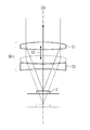
手術用顕微鏡の構造を概略的に示す図1を参照する。本実施の形態において、医学−光学式表示システムは手術用顕微鏡2の一部である。 See FIG. 1, which schematically shows the structure of a surgical microscope. In this embodiment, the medical-optical display system is part of the surgical microscope 2.
手術用顕微鏡2とは、最小侵入性外科および顕微鏡手術で使用される顕微鏡であると理解される。この顕微鏡は比較的に低い倍率(約6〜40倍)を有し、一般的に三次元画像を提供する。拡大は拡大鏡眼鏡を超えている。手術用顕微鏡は医学的分野においてほとんどすべての手術で使用される。 Surgical microscope 2 is understood to be a microscope used in minimally invasive surgery and microsurgery. This microscope has a relatively low magnification (about 6-40 times) and generally provides a three-dimensional image. The magnification exceeds the magnifying glass. Surgical microscopes are used in almost all surgeries in the medical field.
図1に示した手術用顕微鏡2は、物体領域3の方に向けられた対物レンズ5を備えている。この対物レンズは特に色消し対物レンズまたはアポクロマート対物レンズとして形成可能である。本実施の形態では、対物レンズ5は色消し対物レンズを形成する、互いに接合された2枚の部分レンズからなっている。物体領域3は対物レンズ5の焦点面内に配置されるので、対物レンズ5によって無限に結像される。換言すると、物体領域3から出る発散する光線束7A、7Bは対物レンズ5を通過する際に平行な光線束9に変換される。 The surgical microscope 2 shown in FIG. 1 includes an objective lens 5 directed toward the object region 3. This objective lens can be formed particularly as an achromatic objective lens or an apochromat objective lens. In the present embodiment, the objective lens 5 is composed of two partially bonded partial lenses forming an achromatic objective lens. Since the object region 3 is arranged in the focal plane of the objective lens 5, it is infinitely imaged by the objective lens 5. In other words, the light beam bundles 7A and 7B diverging from the object region 3 are converted into parallel light beam bundles 9 as they pass through the objective lens 5.
対物レンズ5の観察者側に、倍率変更器11が配置されている。この倍率変更器は図示した実施の形態のように、倍率を無段階に変更するためのズームシステムとしてあるいは倍率を段階的に変更するためのガリレオ変更器として形成可能である。例えば3枚のレンズを有する組合せレンズによって形成されたズームシステムでは、倍率を変更するために、物体側の両レンズをスライドさせることができる。ズームシステムは実際には、3枚よりも多いレンズ、例えば4枚以上のレンズを備えることができる。この場合、外側のレンズは固定配置可能である。それに対してガリレオ変更器では、固定された複数のレンズ組合せが設けられている。このレンズ組合せはいろいろな倍率を有し、変更時に光線経路内に入れることができる。ズームシステムとガリレオ変更器は双方共、物体側の発散性光線束を、異なる束直径を有する観察者側の平行な光線束に変換する。倍率変更器11は本実施の形態では、手術用顕微鏡2の双眼の光線経路の一部である。すなわち、倍率変更器は手術用顕微鏡2の立体視的な各部分光線経路9A、9Bのための固有のレンズ組合せを備えている。倍率変更器11を用いた倍率の調節は本実施の形態では、モータ駆動のアクチュエータを介して行われる。このアクチュエータは倍率変更器11と共に、倍率を調節するための倍率変更ユニットの一部である。
A
本例では倍率変更器11の観察者側に、インターフェース構造体13A、13Bが接続している。このインターフェース構造体を介して外部の機器を手術用顕微鏡2に接続することができる。インターフェース構造体は本実施の形態ではビームスプリッタプリズム15A、15Bを含んでいる。しかし基本的には、他の種類のビームスプリッタ、例えば部分透過性の鏡を使用することもできる。インターフェース構造体13A、13Bは本実施の形態では、手術用顕微鏡2の光線経路から光線束を出射する働きをする(ビームスプリッタプリズム15B)かあるいは手術用顕微鏡2の光線経路に光線束を入射する働きをする(ビームスプリッタプリズム15A)。
In this example, the
部分光線経路9A内のビームスプリッタプリズム15Aは本実施の形態では、ビームスプリッタプリズム15Aを経て、ディスプレイ37、例えばデジタルモニタ装置(DMD)またはLCDディスプレイと、付属の光学系39とによって、部分光線経路9A内を映して、手術者のための情報またはデータを調べるために役立つ。他の部分光線経路9Bでは、カメラ21を固定したカメラアダプタ19がインターフェース構造体13Bに配置されている。このカメラは電子式画像センサ23、例えばCCDセンサまたはCMOSセンサを備えている。カメラ21によって、組織範囲3の電子画像、特にデジタル画像を撮影することができる。画像センサとして特にハイパースペクトルセンサを使用することができる。このハイパースペクトルセンサでは、3つのスペクトルチャンネル(例えば赤、緑および青)だけでなく、多数のスペクトルチャンネルが存在する。深部情報を有する画像を提供できるようにするために、各部分光線経路9A、9B内にそれぞれ、各カメラに付設された構成要素を備えたカメラを設けることができる(図示せず)。さらに、深さ情報を有する画像データセットBDを提供できるようにするために、各部分光線経路9A、9B内にはそれぞれ、各ディスプレイに付設された構成要素を備えたディスプレイを設けることができる(図示せず)。
In the present embodiment, the
本例では、インターフェース構造体13A、13Bの観察者側に双眼鏡胴27が接続している。この双眼鏡胴は2個の鏡胴レンズ29A、29Bを備えている。この鏡胴レンズはそれぞれ平行な光線束9A、9Bをそれぞれの中間画像面31A、31Bに集束させる、すなわち観察物体3をそれぞれの中間画像面31A、31Bに結像する。中間画像面31A、31B内にある中間画像が最後に、接眼レンズ35A、35Bによって再び無限に結像されるので、観察者は中間画像をリラックスした眼で観察することができる。さらに、部分光線束9A、9Bの間隔を観察者の眼の間隔に合わせるために、双眼鏡胴内で、鏡系によってあるいはプリズム33A、33Bによって、この部分光線束の間隔が増大させられる。鏡系あるいはプリズム33A、33Bによってさらに、画像の配向が行われる。
In this example, the
双眼鏡胴27とインターフェース構造体13A、13Bはこの手術用顕微鏡において医学−光学式表示システムを形成する。この場合、データオーバーレイユニットはビームスプリッタプリズム15Aとディスプレイ37とレンズ39によって形成されている。
The
手術用顕微鏡2はさらに、照明装置を装備している。この照明装置によって、物体領域3を広帯域の照明光で照らすことができる。そのために、本例において、照明装置は白光源41、例えばハロゲン白熱電球または蛍光灯を備えている。物体領域3を照らすために、白光源41から出た光は方向変更ミラー43または方向変更プリズムを経て物体領域3の方へ案内される。照明装置内にはさらに、照明光学系45が設けられている。この照明光学系は観察される物体領域3全体を均一に照らす働きをする。
The surgical microscope 2 is further equipped with a lighting device. With this illumination device, the object region 3 can be illuminated with a wide band illumination light. Therefore, in this example, the illuminator comprises a
図1に示した照明光線経路は非常に簡略化して示され、必ずしも照明光線経路の実際の経過を表してはいないことに留意すべきである。基本的には、照明光線経路はいわゆる斜めの照明として形成可能である。この斜めの照明は図1の概略図に最も近い。このような斜めの照明では、光線経路は対物レンズ5の光学軸線に対して比較的に大きな角度(6°以上)をなし、図1に示すように対物レンズの完全に外側で延びている。しかし、その代わりに、斜めの照明の光線経路が対物レンズ5の縁部領域を通過していてもよい。照明光線経路の他の配置例は、いわゆる0°照明である。この0°照明の場合、照明光線経路は対物レンズ5を通過し、両部分光線経路9A、9Bの間を対物レンズ5の光学軸線に沿って物体領域3の方に向かって対物レンズに入射する。最後に、照明光線経路はいわゆる同軸照明として形成可能である。この同軸照明では、第1と第2の照明部分光線経路が設けられている。照明部分光線経路は1つまたは複数のビームスプリッタを経て、観察部分光線経路9A、9Bの光学軸線に対して平行に手術用顕微鏡2に入射する。従って、照明は両観察部分光線経路に対して同軸に延びている。
It should be noted that the illumination ray path shown in FIG. 1 is shown in a very simplified manner and does not necessarily represent the actual course of the illumination ray path. Basically, the illumination ray path can be formed as so-called oblique illumination. This oblique illumination is closest to the schematic of FIG. In such oblique illumination, the light path makes a relatively large angle (6 ° or more) with respect to the optical axis of the objective lens 5 and extends completely outside the objective lens as shown in FIG. However, instead, the light path of the oblique illumination may pass through the edge region of the objective lens 5. Another arrangement example of the illumination ray path is so-called 0 ° illumination. In the case of this 0 ° illumination, the illumination ray path passes through the objective lens 5 and enters the objective lens between the two
図1に示した手術用顕微鏡2の実施の形態では、対物レンズ5が一定焦点距離の色消しレンズだけからなっている。しかし、複数のレンズからなる対物レンズ系、特にいわゆるバリオスコープ(Varioskop)対物レンズを使用することもできる。このバリオスコープ対物レンズによって、手術用顕微鏡2の作業間隔、すなわち物体焦点間隔とも呼ばれる、対物レンズ5の物体側の第1レンズ面の頂部と物体側の焦点面の間隔を変更することができる。バリオスコープ対物レンズ50によってさらに、焦点面内に配置した物体領域3が無限に結像されるので、観察者側で平行な光線束が存在する。
In the embodiment of the surgical microscope 2 shown in FIG. 1, the objective lens 5 is composed of only an achromatic lens having a constant focal length. However, an objective lens system composed of a plurality of lenses, particularly a so-called Varioskop objective lens, can also be used. With this varioscope objective lens, it is possible to change the working interval of the surgical microscope 2, that is, the interval between the top of the first lens surface on the object side of the objective lens 5 and the focal plane on the object side, which is also called the object focal interval. Since the object region 3 arranged in the focal plane is infinitely imaged by the varioscope
バリオスコープ対物レンズの一例が図2に概略的に示してある。バリオスコープ対物レンズ50は正レンズ51、すなわち正の屈折力を有する光学素子を備えている。この正レンズは図2では凸レンズとして概略的に示してある。バリオスコープ対物レンズ50はさらに、負レンズ52、すなわち負の屈折力を有する光学素子を備えている。この負レンズは図2では凹レンズとして概略的に示してある。負レンズ52は正レンズ51と物体領域3の間にある。図示したバリオスコープ対物レンズ50では、負レンズ52が固定または定置されて配置され、これに対して正レンズ51が両方向矢印53によって示すように、光学軸線OAに沿って摺動可能に配置されている。正レンズ51が図2において破線で示した位置に摺動させられると、焦点間隔が変化するので、物体領域3からの手術用顕微鏡2の作業間隔が変化する。
An example of a varioscope objective lens is schematically shown in FIG. The varioscope
図2では正レンズ51が摺動可能に形成されているが、基本的には、正レンズ51の代わりに負レンズ52を光学軸線OAに沿って移動可能に配置することができる。しかし、負レンズ52は往々にしてバリオスコープ対物レンズ50の終端レンズを形成する。従って、固定された負レンズ52は、手術用顕微鏡2の内部を外部の影響から容易に封止することができるという利点がある。さらに、図2では正レンズ51と負レンズ52を単一レンズとして示しているが、例えばバリオスコープ対物レンズを色消しにまたはアポクロマートに形成するために、この正レンズと負レンズの各々を単一レンズの代わりにレンズグループまたはキットレンズの形に形成することができる。
Although the
図3はデジタル式手術用顕微鏡48の一例を概略的に示す。この手術用顕微鏡48の場合、主対物レンズ5、倍率変更器11および照明系41、43、45は、図1に示した手術用顕微鏡2のものと見た目が異なっていない。違いは、図3に示した手術用顕微鏡48が光学式双眼鏡胴を備えていないことにある。図1の鏡胴対物レンズ29A、29Bの代わりに、図3の手術用顕微鏡48は集束レンズ49A、49Bを備えている。この集束レンズによって、双眼の観察光線経路9A、9Bはデジタル式画像センサ61A、61B上に結像される。その際、デジタル式画像センサ61A、61Bは例えばCCDセンサまたはCMOSセンサである。画像センサ61A、61Bによって撮影された画像はデジタル式ディスプレイ63A、63Bにデジタルで送信される。このディスプレイはLEDディスプレイ、LCDディスプレイまたは有機光ダイオード(OLED)に基づくディスプレイとして形成可能である。ディスプレイ63A、63Bには本例のように接眼レンズ65A、65Bが付設されている。この接眼レンズによって、ディスプレイ63A、63Bに示された画像が無限大に結像されるので、観察者はこの画像をリラックスした眼で観察することができる。この手術用顕微鏡では、ディスプレイ63A、63Bと接眼レンズ65A、65Bは医学−光学式表示システムを形成する。その際、データオーバーレイユニットは、ディスプレイ63A、63B上に示された少なくとも1つの画像内の画像データセットをオーバーレイするためのデジタルユニットである。対応する画像には、画像データセットの画像が電子的に重ねられる。ディスプレイ63A、63Bと接眼レンズ65A、65Bはデジタル式双眼鏡胴の一部であってもよいし、また例えばデータ眼鏡のような、頭に支持されるディスプレイ(頭取付けディスプレイ、HMD)の一部であってもよい。頭取付けディスプレイは仮想リアリティディスプレイまたは拡張リアリティディスプレイとして形成可能である。
FIG. 3 schematically shows an example of a digital
図3は図1のように、一定の焦点距離を有する色消しレンズ5だけを示しているが、図3に示した手術用顕微鏡48は図1に示した手術用顕微鏡2のように、対物レンズ5の代わりに、バリオスコープ対物レンズを備えていてもよい。図3にはさらに、画像センサ61A、61Bによって撮影された画像を、導線67A、67Bによってディスプレイ63A、63Bに伝送することが示してある。しかし、特にディスプレイ63A、63Bが頭取付けディスプレイの一部であるときに、導線接続の代わりに、無線で画像をディスプレイ63A、63Bに伝送することができる。
FIG. 3 shows only the achromatic lens 5 having a constant focal length as shown in FIG. 1, but the
さらに、図4を参照する。 Further, refer to FIG.
手術用顕微鏡2によって物体Oから得られる物体画像OBを、手術者が医学−光学式表示システムによって観察する筋書きが示してある。物体Oは単一物体でもよいし、物体のグループでもよい。さらに、物体Oは例えば手術領域のような範囲であってもよいので、関心のある領域(ROI)である。物体画像OBのその他の範囲は手術領域の周囲を示す。物体画像OBが図1に示した手術用顕微鏡2の光線経路または図3に示した手術用顕微鏡48の光線経路を通過することに留意すべきである。換言すると、物体画像は光学的または電子的に表示される光学データである。
A scenario is shown in which an operator observes an object image OB obtained from an object O by a surgical microscope 2 by a medical-optical display system. The object O may be a single object or a group of objects. Further, the object O may be a range such as a surgical area and is therefore an area of interest (ROI). The other area of the object image OB shows the perimeter of the surgical area. It should be noted that the object image OB passes through the ray path of the surgical microscope 2 shown in FIG. 1 or the ray path of the
例えば機器の状態報告のような追加情報を手術者に提供するために、医学−光学式表示システムは、物体画像OB内への画像データセットBDのデータオーバーレイするための装置を備えている。この場合、画像データセットBDの可視化は追加情報を提供する。そのための装置は例えばビームプリッタプリズム15Bとのインターフェース構造体13Bと、付設の光学系を有するディスプレイ37を備えている。すなわち、運転中、電子形式で存在する画像データセットBDは、ディスプレイ37によって光学データに変換され、手術用顕微鏡2の光線経路内に入射または反映される。これとは異なり、オーバーレイは画像内容の電子的な重なりを含んでいる。すなわち、画像データセットBDは電子形式で存在し、画像の一部を置き換えるか電子的に明瞭にまたは不明瞭に重ねることにより、電子的に存在する画像(これは例えば図3に示した手術用顕微鏡48におけるような画像)で使用される。
To provide the surgeon with additional information, such as device status reports, the medical-optical display system includes a device for data overlaying the image dataset BD into the object image OB. In this case, the visualization of the image dataset BD provides additional information. The device for that purpose includes, for example, an
さらに、図5を参照して、装置70の構造を説明する。この装置は運転中、画像データセットBDのデータオーバーレイが、物体画像BDの関連する画像内容との重なりにならないようにする。 Further, the structure of the device 70 will be described with reference to FIG. The device ensures that the data overlay of the image dataset BD does not overlap with the relevant image content of the object image BD during operation.
装置70は本実施の形態では、範囲決定ユニット72と、データオーバーレイユニット74を備えている。範囲決定ユニット72によって、物体画像OB内の小さな活動度を有する範囲Bを決定することができ一方、データオーバーレイユニット74によって、この範囲B内で画像データセットBDをオーバーレイすることができる。この場合、小さな活動度を有する範囲Bは例えば、手術者が活動的ではなく、従って画像内容を少しだけ変更することになる物体画像OB内の範囲である。画像内容の少しでない変更または高い可変性は例えば、適当な領域において手術者の指が活動的であるときあるいは外科用器具が動くときに存在する。それによってそれぞれのピクセルの強度値が強く変化する。
In the present embodiment, the device 70 includes a
範囲決定ユニット72は本実施の形態では、読み込みユニット76、評価ユニット80、比較ユニット82、クラスタユニット84および決定ユニット86を備えている。
In the present embodiment, the
読み込みユニット76はソース画像データセットRDを読み込む。ソース画像データセットRDは個々の物体画像OBの時間的なシーケンスを形成する。このシーケンスは物体画像OB内に示されたことの時間的な経過を示す。この場合、ソース画像データセットRDは物体Oを撮影したビデオストリームのビデオシーケンスであってもよい。その際、ソース画像データセットは例えば図1のカメラ21によってあるいは図3の画像センサ61A、61Bによって生じることができる。複数のカメラ21が使用されると、それぞれのソース画像データセットが先ず最初に融合(登録またはステッチ)させられる。ソース画像データセットRDは好ましくは、少なくとも、オーバーレイされた画像データセットBDが時間的に可変の画像内容を含んでいるときには、オーバーレイされた画像データセットBDを含んでいない。
The
評価ユニット80はソース画像データセットの画像点の時間的な可変性Vを決定する。この可変性は、画像点を示す画像部分内の時間的な変化を表す。その際、画像点はソース画像データセットRDのピクセルあるいはソース画像データセットRDの2×2、2×3、2×4、3×3、3×4、4×4等のピクセルのピクセルグループである。その際、時間的な可変性は例えば時間的に連続するソース画像内の同じピクセルの間のピクセル値の差の合計によって決定可能である。大きな値を有するピクセル値の差が頻繁に発生すればするほど、合計は大きくなる。それに対して、小さな値だけを有するピクセル値の差の場合には、合計が小さい。ピクセルグループの場合には、差の値の合計に、ピクセルグループについて決定されたピクセル値が合算される。合計を求める際に、好ましくは物体画像が用いられる。現在の物体画像から出発して所定の時間をさかのぼる物体画像が用いられる。この時間は、画像内容のいろいろな時間的ダイナミクスに適合できるようにするために調節可能である。その際、迅速に変化する画像内容は、ゆっくり変化する画像内容よりも短い時間を必要とする。
The
比較ユニット82は時間的な可変性Vを、設定された可変性限界値GVと比較する。この可変性限界値は、活動度の小さな範囲B内で予想される、画像点の時間的な可変性Vを考慮できるようにするために調節可能である。範囲Bにおいて比較的に小さな時間的可変性Vが予想されると、比較的に大きな(しかし、高い活動度を有する範囲よりも常に小さい)時間的な可変性Vが範囲B内で予想されるときよりも、可変性限界値は低く保つことができる。
The
クラスタユニット84は、検出された時間的な可変性が可変性限界値GVを下回る画像点を集合させる。集合の結果として、小さな時間的可変性を有する1つまたは複数のまとまりのある領域が形成される。さらに、画像処理ユニットを任意選択的に設けることができる。この画像処理ユニットは形態学的画像処理によって、小さな時間的可変性を有するまとまりのある個々の領域を、小さな時間的可変性を有するまとまりのある大きな1つの領域に統合する。決定ユニット86は、小さな活動度を有する範囲Bよりも小さな時間的可変性を有する少なくとも1つのまとまりのある領域を決定する。
The
データオーバーレイユニット74は本実施の形態では、画像データセットのオーバーレイが行われる、小さな活動度を有する範囲B内の場所を決定するために、画像データセットBDの大きさおよび/または形を考慮するように形成されている。それによって、オーバーレイされる画像データセットBDの大きさおよび/または形にとって適している、小さな活動度を有する範囲B内の個所で、オーバーレイを行うことができる。
In this embodiment, the
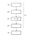
さらに図6を参照して、方法について説明する。この方法によって、画像データセットBDのデータオーバーレイの際に、物体画像OBの画像内容との重なりがなくなる。そのために、第1ステップS100において、小さな活動度を有する範囲Bが物体画像OB内で決定される。他のステップS200において、決定された範囲B内で画像データセットのオーバーレイが行われる。 Further, the method will be described with reference to FIG. By this method, there is no overlap with the image content of the object image OB at the time of data overlay of the image data set BD. Therefore, in the first step S100, the range B having a small activity is determined in the object image OB. In another step S200, the image data set is overlaid within the determined range B.
小さな活動度を有する範囲Bを決定するために、中間ステップS110において、物体画像OBのソース画像データセットRDが検出され、ソース画像データセットの画像点の時間的な可変性Vが決定される(中間ステップ120)。決定された時間的可変性Vは、設定された可変性限界値GVと比較され(中間ステップS130)、決定された時間的可変性が可変性限界値GVを下回る画像点が集合させられる(中間ステップS140)。それによって、小さな時間的可変性を有するまとまりのある少なくとも1つの領域を発生することができる。最後に、小さな時間的可変性を有するまとまりのある少なくとも1つの領域が、小さな可変性を有する範囲Bとして決定される(中間ステップS150)。 In order to determine the range B having a small degree of activity, in the intermediate step S110, the source image data set RD of the object image OB is detected and the temporal variability V of the image points of the source image data set is determined ( Intermediate step 120). The determined temporal variability V is compared with the set variability limit value GV (intermediate step S130), and image points whose determined temporal variability is less than the variability limit value GV are aggregated (intermediate). Step S140). Thereby, at least one cohesive region with small temporal variability can be generated. Finally, at least one cohesive region with small temporal variability is determined as range B with small variability (intermediate step S150).
方法の発展形態において、観察物体の深さマップは、高い活動度が予想される所定の範囲を最初から排除する働きをする。例えば深い手術管の場合、高い活動度が特に手術管の範囲内に予想される。 In a developed form of the method, the depth map of the observed object serves to eliminate from the beginning a predetermined range where high activity is expected. For example, in the case of a deep surgical tube, high activity is expected, especially within the range of the surgical tube.
小さな活動度を有する範囲Bが物体画像OB内で決定されるステップは、適切なアルゴリズムによって実施可能である。可能なアルゴリズムアプローチは例えば、光学的流れまたは例えば神経網による機械的学習を用いた分析である。方法は、カメラ21のデータを読み込んで、ディスプレイ37の制御ための画像データセットBDを出力するために、医学−光学式観察装置にデータ伝送するように接続されたPCまたはコンピュータによって実施可能である。そのために、PCまたはコンピュータは適当なハードウェア構成要素および/またはソフトウェア構成要素を備えることができる。その代わりに、方法は、医学−光学式観察装置に所属する、適当なハードウェア構成要素および/またはソフトウェア構成要素を備えた計算機モジュールによっても実施することができる。
The step in which the range B with a small activity is determined in the object image OB can be performed by an appropriate algorithm. Possible algorithmic approaches are, for example, analysis using optical flow or, for example, mechanical learning with a neural network. The method can be performed by a PC or computer connected to read the data from the
本発明を実施の形態に基づいて説明のために詳述した。しかし、専門家は、本発明の範囲内で、実施の形態を逸脱可能であることを知っている。本実施の形態と異なり、医学−光学式表示システムは例えば内視鏡の一部としてまたは内部顕微鏡として形成することが可能である。専門家は、実施の形態を本発明の範囲内で変形する他の例を知っている。従って、本発明は、上記の実施の形態に限定されるものではなく、添付の特許請求の範囲によってのみ限定される。 The present invention has been described in detail for illustration based on embodiments. However, experts know that it is possible to deviate from embodiments within the scope of the present invention. Unlike this embodiment, the medical-optical display system can be formed, for example, as part of an endoscope or as an internal microscope. Experts are aware of other examples of modifying embodiments within the scope of the present invention. Therefore, the present invention is not limited to the above embodiments, but is limited only by the appended claims.
2 手術用顕微鏡
3 手術領域/観察物体
5 対物レンズ
7 光線束
9 光線束
9A 立体視的な部分光線経路
9B 立体視的な部分光線経路
11 倍率変更器
13A インターフェース構造体
13B インターフェース構造体
15A ビームスプリッタプリズム
15B ビームスプリッタプリズム
19 カメラアダプタ
21 カメラ
23 画像センサ
27 双眼鏡胴
29A 鏡胴レンズ
29B 鏡胴レンズ
31A 中間画像面
31B 中間画像面
33A プリズム
33B プリズム
35A 接眼レンズ
35B 接眼レンズ
37 ディスプレイ
39 光学系
41 白光源
43 方向変更鏡
45 照明光学系
48 手術用顕微鏡
49A 集束レンズ
49B 集束レンズ
50 バリオ対物レンズ
51 正レンズ
52 負レンズ
53 両方向矢印
61A 画像センサ
61B 画像センサ
63A ディスプレイ
63B ディスプレイ
65A 接眼レンズ
65B 接眼レンズ
67A 導線
67B 導線
70 装置
72 範囲決定ユニット
74 データオーバーレイユニット
76 読み込みユニット
80 評価ユニット
82 クラスタユニット
84 比較ユニット
86 決定ユニット
B 範囲
BD 画像データセット
O 物体
OA 光学軸線
OB 物体画像
RD ソース画像データセット
V 可変性
GV 可変性限界値
S100 小さな活動度を有する範囲の決定
S110 ソース画像データセットの検出
S120 画像点の時間的可変性の決定
S130 時間的な可変性と、設定された可変性限界値との比較
S140 集合
S150 小さな活動度を有する範囲の決定
S200 画像データセットのオーバーレイ
2 Surgical microscope 3 Surgical area / observation object 5
Claims (14)
前記物体画像(OB)内で小さな活動度を有する少なくとも1つの範囲(B)を決定するステップ(S100)と、
小さな活動度を有する少なくとも1つの前記範囲(B)内で少なくとも1つの前記画像データセット(BD)をオーバーレイするステップ(S200)
を有し、
前記範囲(B)決定するために、次の中間ステップ、すなわち
個々の物体画像(OB)の時間的なシーケンスを示すソース画像データセット(RD)を検出するステップ(S110)と、
前記ソース画像データセットの複数の画像点の時間的な可変性(V)を決定するステップ(S120)と、
時間的な前記可変性(V)を設定された可変性限界値(GV)と比較するステップ(S130)と、
小さな時間的可変性を有するまとまりのある少なくとも1つの領域を発生するために、決定された時間的可変性が前記可変性限界値(GV)を下回る複数の画像点を集合するステップ(S140)と、
小さな活動度を有する少なくとも1つの範囲(B)として、小さな時間的可変性を有するまとまりのある少なくとも1つの領域を定めるステップ(S150)
とが実施されることを特徴とする方法。 A medical-optical observation device (2, 48), wherein the medical-optical display system comprises a data overlay unit (74) for data overlaying at least one image data set (BD) onto an object image (OB). A method for activating a medical-optical display system for displaying an object image (OB) of an observed object (O) obtained by.
A step (S100) of determining at least one range (B) having a small activity in the object image (OB).
A step (S200) of overlaying at least one image data set (BD) within at least one range (B) having a small activity.
Have a,
The next intermediate step, i.e., to determine the range (B).
A step (S110) of detecting a source image dataset (RD) showing a temporal sequence of individual object images (OBs), and
A step (S120) of determining the temporal variability (V) of a plurality of image points of the source image data set, and
A step (S130) of comparing the temporal variability (V) with a set variability limit value (GV), and
With the step (S140) of assembling a plurality of image points whose determined temporal variability is less than the variability limit value (GV) in order to generate at least one cohesive region having a small temporal variability. ,
Step (S150) of defining at least one cohesive region with small temporal variability as at least one range (B) with small activity.
A method characterized in that and is carried out.
少なくとも1つの画像データセット(BD)を前記物体画像(OB)にオーバーレイするように形成されたデータオーバーレイユニット(74)と、
前記物体画像(OB)内で小さな活動度を有する少なくとも1つの範囲(B)を決定するように形成された範囲決定ユニット(72)とを備え、
前記データオーバーレイユニット(74)が、小さな活動度を有する前記物体画像(OB)の少なくとも1つの範囲(B)内に少なくとも1つの画像データセット(BD)をオーバーレイするように形成され、
前記範囲決定ユニット(72)が、
個々の物体画像(OB)の時間的なシーケンスを示すソース画像データセット(RD)を読み込むための読み込みユニット(76)と、
前記ソース画像データセットの複数の画像点の時間的な可変性(V)を決定するための評価ユニット(80)と、
前記の時間的な可変性(V)を設定された可変性限界値(GV)と比較するための比較ユニット(82)と、
小さな時間的可変性を有する少なくとも1つのまとまりのある領域を発生するために、決定された時間的可変性が可変性限界値(GV)を下回る複数の画像点を集合させるためのクラスタユニット(84)と、
小さな活動度を有する少なくとも1つの範囲(B)として、小さな時間的可変性を有する少なくとも1つのまとまりのある領域を定めるための決定ユニット(86)と
を含んでいることを特徴とする、
医学−光学式表示システム。 A medical-optical display system for displaying an object image (OB) obtained by a medical-optical observation device (2, 48).
A data overlay unit (74) formed to overlay at least one image data set (BD) on the object image (OB).
It comprises a range determining unit (72) formed to determine at least one range (B) having a small activity in the object image (OB).
The data overlay unit (74) is formed so as to overlay at least one image data set (BD) in said at least one range of the object image (OB) (B) having a small activity,
The range determination unit (72)
A reading unit (76) for reading a source image dataset (RD) showing a temporal sequence of individual object images (OBs), and
An evaluation unit (80) for determining the temporal variability (V) of a plurality of image points in the source image data set, and
A comparison unit (82) for comparing the temporal variability (V) with the set variability limit value (GV), and
A cluster unit (84) for aggregating multiple image points whose determined temporal variability is below the variability limit (GV) in order to generate at least one cohesive region with small temporal variability. )When,
With a determination unit (86) for defining at least one cohesive region with small temporal variability as at least one range (B) with small activity.
Characterized by containing,
Medicine-Optical display system.
前記決定ユニット(86)が、小さな時間的可変性を有するまとまりのある大きな領域を、小さな活動度を有する少なくとも1つの範囲(B)として定めるように形成されていることを特徴とする請求項8または9に記載の医学−光学式表示システム。 An image processing unit (85) is provided, which integrates individual cohesive areas with small temporal variability into large cohesive areas with small temporal variability by image processing.
Claim 8 wherein the determining unit (86), a large region of unity with a small temporal variability, characterized in that it is formed to define a least one range (B) having a small activity Or the medical-optical display system according to 9.
Applications Claiming Priority (2)
| Application Number | Priority Date | Filing Date | Title |
|---|---|---|---|
| DE102017108371.5 | 2017-04-20 | ||
| DE102017108371.5A DE102017108371B4 (en) | 2017-04-20 | 2017-04-20 | Medical optical display system and method for operating the same |
Publications (3)
| Publication Number | Publication Date |
|---|---|
| JP2018181333A JP2018181333A (en) | 2018-11-15 |
| JP2018181333A5 JP2018181333A5 (en) | 2020-08-27 |
| JP6893896B2 true JP6893896B2 (en) | 2021-06-23 |
Family
ID=63714646
Family Applications (1)
| Application Number | Title | Priority Date | Filing Date |
|---|---|---|---|
| JP2018073624A Active JP6893896B2 (en) | 2017-04-20 | 2018-04-06 | Medicine-How to activate an optical display system |
Country Status (4)
| Country | Link |
|---|---|
| US (1) | US10989911B2 (en) |
| JP (1) | JP6893896B2 (en) |
| CN (1) | CN108720934A (en) |
| DE (1) | DE102017108371B4 (en) |
Families Citing this family (6)
| Publication number | Priority date | Publication date | Assignee | Title |
|---|---|---|---|---|
| WO2020066043A1 (en) | 2018-09-28 | 2020-04-02 | オリンパス株式会社 | Microscope system, projection unit, and image projection method |
| CN112714886B (en) * | 2018-09-28 | 2023-03-21 | 仪景通株式会社 | Microscope system, projection unit, and image projection method |
| JP7150868B2 (en) | 2018-09-28 | 2022-10-11 | 株式会社エビデント | Microscope system, projection unit, and image projection method |
| CN110200707A (en) * | 2019-06-28 | 2019-09-06 | 上海德芬生物科技有限公司 | A kind of operating microscope system and imaging method showing blood flow information |
| DE102021101694A1 (en) * | 2021-01-26 | 2022-07-28 | Carl Zeiss Meditec Ag | Tool-Type-Agnostic Assistive Functionality in Surgical Procedures |
| CN113885300A (en) * | 2021-09-14 | 2022-01-04 | 拾斛科技(南京)有限公司 | Wafer alignment microscope, photoetching machine, bonding machine and stamping machine |
Family Cites Families (22)
| Publication number | Priority date | Publication date | Assignee | Title |
|---|---|---|---|---|
| JP3625906B2 (en) * | 1995-08-23 | 2005-03-02 | オリンパス株式会社 | Surgical microscope equipment |
| US6661571B1 (en) * | 1999-09-21 | 2003-12-09 | Olympus Optical Co., Ltd. | Surgical microscopic system |
| JP4804675B2 (en) * | 2001-09-05 | 2011-11-02 | オリンパス株式会社 | Surgical microscope |
| CN100501492C (en) * | 2004-07-16 | 2009-06-17 | 卡尔蔡司医疗技术股份公司 | Device for machining an object by means of laser radiation |
| US8094914B2 (en) * | 2004-09-22 | 2012-01-10 | Nikon Corporation | Microscope system and image processing method used for observation of a specimen |
| US8820929B2 (en) * | 2006-01-20 | 2014-09-02 | Clarity Medical Systems, Inc. | Real-time measurement/display/record/playback of wavefront data for use in vision correction procedures |
| JP2009124510A (en) * | 2007-11-15 | 2009-06-04 | Canon Inc | Display control apparatus and method thereof, program, and recording medium |
| DE102008028482B4 (en) * | 2008-06-13 | 2021-11-25 | Carl Zeiss Meditec Ag | Optical observation device with multi-channel data overlay and method for overlaying electronic overlay images in an optical observation device |
| DE102008040802B4 (en) * | 2008-07-28 | 2014-09-18 | Carl Zeiss Meditec Ag | Method for the quantitative representation of blood flow as well as surgical microscope and analysis system |
| JP5465620B2 (en) | 2010-06-25 | 2014-04-09 | Kddi株式会社 | Video output apparatus, program and method for determining additional information area to be superimposed on video content |
| EP2581034B1 (en) * | 2011-10-11 | 2016-02-17 | Tobii AB | Eye-tracker illumination |
| JP6039903B2 (en) * | 2012-01-27 | 2016-12-07 | キヤノン株式会社 | Image processing apparatus and operation method thereof |
| JP5826727B2 (en) * | 2012-08-27 | 2015-12-02 | オリンパス株式会社 | Medical system |
| JP6402717B2 (en) * | 2013-09-18 | 2018-10-10 | 株式会社ニコン | Image analysis apparatus, image analysis method, image analysis program, cell manufacturing method, cell manufacturing apparatus, cell culture method, and cell culture apparatus |
| EP3087424A4 (en) * | 2013-12-23 | 2017-09-27 | Camplex, Inc. | Surgical visualization systems |
| EP3090322A4 (en) * | 2013-12-31 | 2017-07-19 | Eyefluence, Inc. | Systems and methods for gaze-based media selection and editing |
| DE102014102425B4 (en) * | 2014-02-25 | 2018-06-28 | Carl Zeiss Meditec Ag | Microscope system and microscopy method using digital markers |
| DE102014210150A1 (en) | 2014-05-27 | 2015-12-03 | Carl Zeiss Meditec Ag | Optical assembly with a display for data input |
| DE102014216718A1 (en) * | 2014-08-22 | 2016-02-25 | Siemens Aktiengesellschaft | Control of the positioning of a scan area of a medical imaging system |
| CH711776B1 (en) * | 2014-10-06 | 2020-04-15 | Zeiss Carl Meditec Ag | Operating system with an OCT device. |
| US9645379B2 (en) * | 2014-12-29 | 2017-05-09 | Novartis Ag | Magnification in ophthalmic procedures and associated devices, systems, and methods |
| US20170035287A1 (en) * | 2015-08-04 | 2017-02-09 | Novartis Ag | Dynamic surgical data overlay |
-
2017
- 2017-04-20 DE DE102017108371.5A patent/DE102017108371B4/en active Active
-
2018
- 2018-04-06 JP JP2018073624A patent/JP6893896B2/en active Active
- 2018-04-12 US US15/951,909 patent/US10989911B2/en active Active
- 2018-04-20 CN CN201810360191.0A patent/CN108720934A/en active Pending
Also Published As
| Publication number | Publication date |
|---|---|
| US20180307034A1 (en) | 2018-10-25 |
| CN108720934A (en) | 2018-11-02 |
| DE102017108371A1 (en) | 2018-10-25 |
| DE102017108371B4 (en) | 2020-08-27 |
| US10989911B2 (en) | 2021-04-27 |
| JP2018181333A (en) | 2018-11-15 |
Similar Documents
| Publication | Publication Date | Title |
|---|---|---|
| JP6893896B2 (en) | Medicine-How to activate an optical display system | |
| JP6930915B2 (en) | Expansion and related devices, systems, and methods in ophthalmic procedures | |
| JP6996518B2 (en) | Branch optical system, imaging device, and imaging system | |
| US11092929B2 (en) | Visualization system and method for generating holographic presentations from optical signals | |
| US11653824B2 (en) | Medical observation system and medical observation device | |
| US20220247981A1 (en) | Signal processing device, signal processing method, image capture device, and medical image capture device | |
| US11698535B2 (en) | Systems and methods for superimposing virtual image on real-time image | |
| US20150346472A1 (en) | Microscope system with depth preview and microscopy method | |
| US10151909B2 (en) | Surgical microscope and method for highlighting eye lens pieces | |
| US10222597B2 (en) | Medical optical observation instrument and method for contrasting polarization-rotating tissue | |
| CN212415706U (en) | Reality augmented microscope | |
| JP6030423B2 (en) | Fundus photographing device | |
| US11310481B2 (en) | Imaging device, system, method and program for converting a first image into a plurality of second images | |
| JP2018063309A (en) | Microscope device | |
| WO2019198293A1 (en) | Microscope system and medical light source device | |
| JP6159446B2 (en) | Fundus photographing device | |
| JP7456385B2 (en) | Image processing device, image processing method, and program | |
| US20170154418A1 (en) | Method of Labeling Invisible Fluorescence by Visible Light with Self-Correction | |
| JP6159445B2 (en) | Fundus photographing device | |
| CN111317439A (en) | Reality augmentation microscope and reality augmentation method thereof | |
| WO2019198189A1 (en) | Microscope device | |
| JP2020525055A (en) | Medical imaging system, method and computer program | |
| TW201944117A (en) | Microscope device that simplifies a lens system configuration of a microscope and clearly observes high-magnification images using an 8K large-screen monitor and digital zoom |
Legal Events
| Date | Code | Title | Description |
|---|---|---|---|
| A521 | Request for written amendment filed |
Free format text: JAPANESE INTERMEDIATE CODE: A523 Effective date: 20200714 |
|
| A621 | Written request for application examination |
Free format text: JAPANESE INTERMEDIATE CODE: A621 Effective date: 20200714 |
|
| A871 | Explanation of circumstances concerning accelerated examination |
Free format text: JAPANESE INTERMEDIATE CODE: A871 Effective date: 20200714 |
|
| A975 | Report on accelerated examination |
Free format text: JAPANESE INTERMEDIATE CODE: A971005 Effective date: 20200722 |
|
| A977 | Report on retrieval |
Free format text: JAPANESE INTERMEDIATE CODE: A971007 Effective date: 20201028 |
|
| A131 | Notification of reasons for refusal |
Free format text: JAPANESE INTERMEDIATE CODE: A131 Effective date: 20201110 |
|
| A521 | Request for written amendment filed |
Free format text: JAPANESE INTERMEDIATE CODE: A523 Effective date: 20210205 |
|
| TRDD | Decision of grant or rejection written | ||
| A01 | Written decision to grant a patent or to grant a registration (utility model) |
Free format text: JAPANESE INTERMEDIATE CODE: A01 Effective date: 20210511 |
|
| A61 | First payment of annual fees (during grant procedure) |
Free format text: JAPANESE INTERMEDIATE CODE: A61 Effective date: 20210602 |
|
| R150 | Certificate of patent or registration of utility model |
Ref document number: 6893896 Country of ref document: JP Free format text: JAPANESE INTERMEDIATE CODE: R150 |