JP6892766B2 - Power transmission system for motorcycles - Google Patents
Power transmission system for motorcycles Download PDFInfo
- Publication number
- JP6892766B2 JP6892766B2 JP2017049772A JP2017049772A JP6892766B2 JP 6892766 B2 JP6892766 B2 JP 6892766B2 JP 2017049772 A JP2017049772 A JP 2017049772A JP 2017049772 A JP2017049772 A JP 2017049772A JP 6892766 B2 JP6892766 B2 JP 6892766B2
- Authority
- JP
- Japan
- Prior art keywords
- inner body
- continuously variable
- variable transmission
- drive wheels
- power transmission
- Prior art date
- Legal status (The legal status is an assumption and is not a legal conclusion. Google has not performed a legal analysis and makes no representation as to the accuracy of the status listed.)
- Active
Links
Images


Classifications
-
- B—PERFORMING OPERATIONS; TRANSPORTING
- B60—VEHICLES IN GENERAL
- B60K—ARRANGEMENT OR MOUNTING OF PROPULSION UNITS OR OF TRANSMISSIONS IN VEHICLES; ARRANGEMENT OR MOUNTING OF PLURAL DIVERSE PRIME-MOVERS IN VEHICLES; AUXILIARY DRIVES FOR VEHICLES; INSTRUMENTATION OR DASHBOARDS FOR VEHICLES; ARRANGEMENTS IN CONNECTION WITH COOLING, AIR INTAKE, GAS EXHAUST OR FUEL SUPPLY OF PROPULSION UNITS IN VEHICLES
- B60K17/00—Arrangement or mounting of transmissions in vehicles
- B60K17/04—Arrangement or mounting of transmissions in vehicles characterised by arrangement, location, or kind of gearing
-
- B—PERFORMING OPERATIONS; TRANSPORTING
- B60—VEHICLES IN GENERAL
- B60K—ARRANGEMENT OR MOUNTING OF PROPULSION UNITS OR OF TRANSMISSIONS IN VEHICLES; ARRANGEMENT OR MOUNTING OF PLURAL DIVERSE PRIME-MOVERS IN VEHICLES; AUXILIARY DRIVES FOR VEHICLES; INSTRUMENTATION OR DASHBOARDS FOR VEHICLES; ARRANGEMENTS IN CONNECTION WITH COOLING, AIR INTAKE, GAS EXHAUST OR FUEL SUPPLY OF PROPULSION UNITS IN VEHICLES
- B60K6/00—Arrangement or mounting of plural diverse prime-movers for mutual or common propulsion, e.g. hybrid propulsion systems comprising electric motors and internal combustion engines ; Control systems therefor, i.e. systems controlling two or more prime movers, or controlling one of these prime movers and any of the transmission, drive or drive units Informative references: mechanical gearings with secondary electric drive F16H3/72; arrangements for handling mechanical energy structurally associated with the dynamo-electric machine H02K7/00; machines comprising structurally interrelated motor and generator parts H02K51/00; dynamo-electric machines not otherwise provided for in H02K see H02K99/00
- B60K6/20—Arrangement or mounting of plural diverse prime-movers for mutual or common propulsion, e.g. hybrid propulsion systems comprising electric motors and internal combustion engines ; Control systems therefor, i.e. systems controlling two or more prime movers, or controlling one of these prime movers and any of the transmission, drive or drive units Informative references: mechanical gearings with secondary electric drive F16H3/72; arrangements for handling mechanical energy structurally associated with the dynamo-electric machine H02K7/00; machines comprising structurally interrelated motor and generator parts H02K51/00; dynamo-electric machines not otherwise provided for in H02K see H02K99/00 the prime-movers consisting of electric motors and internal combustion engines, e.g. HEVs
- B60K6/22—Arrangement or mounting of plural diverse prime-movers for mutual or common propulsion, e.g. hybrid propulsion systems comprising electric motors and internal combustion engines ; Control systems therefor, i.e. systems controlling two or more prime movers, or controlling one of these prime movers and any of the transmission, drive or drive units Informative references: mechanical gearings with secondary electric drive F16H3/72; arrangements for handling mechanical energy structurally associated with the dynamo-electric machine H02K7/00; machines comprising structurally interrelated motor and generator parts H02K51/00; dynamo-electric machines not otherwise provided for in H02K see H02K99/00 the prime-movers consisting of electric motors and internal combustion engines, e.g. HEVs characterised by apparatus, components or means specially adapted for HEVs
- B60K6/38—Arrangement or mounting of plural diverse prime-movers for mutual or common propulsion, e.g. hybrid propulsion systems comprising electric motors and internal combustion engines ; Control systems therefor, i.e. systems controlling two or more prime movers, or controlling one of these prime movers and any of the transmission, drive or drive units Informative references: mechanical gearings with secondary electric drive F16H3/72; arrangements for handling mechanical energy structurally associated with the dynamo-electric machine H02K7/00; machines comprising structurally interrelated motor and generator parts H02K51/00; dynamo-electric machines not otherwise provided for in H02K see H02K99/00 the prime-movers consisting of electric motors and internal combustion engines, e.g. HEVs characterised by apparatus, components or means specially adapted for HEVs characterised by the driveline clutches
- B60K6/383—One-way clutches or freewheel devices
-
- B—PERFORMING OPERATIONS; TRANSPORTING
- B60—VEHICLES IN GENERAL
- B60K—ARRANGEMENT OR MOUNTING OF PROPULSION UNITS OR OF TRANSMISSIONS IN VEHICLES; ARRANGEMENT OR MOUNTING OF PLURAL DIVERSE PRIME-MOVERS IN VEHICLES; AUXILIARY DRIVES FOR VEHICLES; INSTRUMENTATION OR DASHBOARDS FOR VEHICLES; ARRANGEMENTS IN CONNECTION WITH COOLING, AIR INTAKE, GAS EXHAUST OR FUEL SUPPLY OF PROPULSION UNITS IN VEHICLES
- B60K6/00—Arrangement or mounting of plural diverse prime-movers for mutual or common propulsion, e.g. hybrid propulsion systems comprising electric motors and internal combustion engines ; Control systems therefor, i.e. systems controlling two or more prime movers, or controlling one of these prime movers and any of the transmission, drive or drive units Informative references: mechanical gearings with secondary electric drive F16H3/72; arrangements for handling mechanical energy structurally associated with the dynamo-electric machine H02K7/00; machines comprising structurally interrelated motor and generator parts H02K51/00; dynamo-electric machines not otherwise provided for in H02K see H02K99/00
- B60K6/20—Arrangement or mounting of plural diverse prime-movers for mutual or common propulsion, e.g. hybrid propulsion systems comprising electric motors and internal combustion engines ; Control systems therefor, i.e. systems controlling two or more prime movers, or controlling one of these prime movers and any of the transmission, drive or drive units Informative references: mechanical gearings with secondary electric drive F16H3/72; arrangements for handling mechanical energy structurally associated with the dynamo-electric machine H02K7/00; machines comprising structurally interrelated motor and generator parts H02K51/00; dynamo-electric machines not otherwise provided for in H02K see H02K99/00 the prime-movers consisting of electric motors and internal combustion engines, e.g. HEVs
- B60K6/22—Arrangement or mounting of plural diverse prime-movers for mutual or common propulsion, e.g. hybrid propulsion systems comprising electric motors and internal combustion engines ; Control systems therefor, i.e. systems controlling two or more prime movers, or controlling one of these prime movers and any of the transmission, drive or drive units Informative references: mechanical gearings with secondary electric drive F16H3/72; arrangements for handling mechanical energy structurally associated with the dynamo-electric machine H02K7/00; machines comprising structurally interrelated motor and generator parts H02K51/00; dynamo-electric machines not otherwise provided for in H02K see H02K99/00 the prime-movers consisting of electric motors and internal combustion engines, e.g. HEVs characterised by apparatus, components or means specially adapted for HEVs
- B60K6/40—Arrangement or mounting of plural diverse prime-movers for mutual or common propulsion, e.g. hybrid propulsion systems comprising electric motors and internal combustion engines ; Control systems therefor, i.e. systems controlling two or more prime movers, or controlling one of these prime movers and any of the transmission, drive or drive units Informative references: mechanical gearings with secondary electric drive F16H3/72; arrangements for handling mechanical energy structurally associated with the dynamo-electric machine H02K7/00; machines comprising structurally interrelated motor and generator parts H02K51/00; dynamo-electric machines not otherwise provided for in H02K see H02K99/00 the prime-movers consisting of electric motors and internal combustion engines, e.g. HEVs characterised by apparatus, components or means specially adapted for HEVs characterised by the assembly or relative disposition of components
-
- B—PERFORMING OPERATIONS; TRANSPORTING
- B60—VEHICLES IN GENERAL
- B60K—ARRANGEMENT OR MOUNTING OF PROPULSION UNITS OR OF TRANSMISSIONS IN VEHICLES; ARRANGEMENT OR MOUNTING OF PLURAL DIVERSE PRIME-MOVERS IN VEHICLES; AUXILIARY DRIVES FOR VEHICLES; INSTRUMENTATION OR DASHBOARDS FOR VEHICLES; ARRANGEMENTS IN CONNECTION WITH COOLING, AIR INTAKE, GAS EXHAUST OR FUEL SUPPLY OF PROPULSION UNITS IN VEHICLES
- B60K6/00—Arrangement or mounting of plural diverse prime-movers for mutual or common propulsion, e.g. hybrid propulsion systems comprising electric motors and internal combustion engines ; Control systems therefor, i.e. systems controlling two or more prime movers, or controlling one of these prime movers and any of the transmission, drive or drive units Informative references: mechanical gearings with secondary electric drive F16H3/72; arrangements for handling mechanical energy structurally associated with the dynamo-electric machine H02K7/00; machines comprising structurally interrelated motor and generator parts H02K51/00; dynamo-electric machines not otherwise provided for in H02K see H02K99/00
- B60K6/20—Arrangement or mounting of plural diverse prime-movers for mutual or common propulsion, e.g. hybrid propulsion systems comprising electric motors and internal combustion engines ; Control systems therefor, i.e. systems controlling two or more prime movers, or controlling one of these prime movers and any of the transmission, drive or drive units Informative references: mechanical gearings with secondary electric drive F16H3/72; arrangements for handling mechanical energy structurally associated with the dynamo-electric machine H02K7/00; machines comprising structurally interrelated motor and generator parts H02K51/00; dynamo-electric machines not otherwise provided for in H02K see H02K99/00 the prime-movers consisting of electric motors and internal combustion engines, e.g. HEVs
- B60K6/50—Architecture of the driveline characterised by arrangement or kind of transmission units
- B60K6/54—Transmission for changing ratio
- B60K6/543—Transmission for changing ratio the transmission being a continuously variable transmission
-
- B—PERFORMING OPERATIONS; TRANSPORTING
- B62—LAND VEHICLES FOR TRAVELLING OTHERWISE THAN ON RAILS
- B62M—RIDER PROPULSION OF WHEELED VEHICLES OR SLEDGES; POWERED PROPULSION OF SLEDGES OR SINGLE-TRACK CYCLES; TRANSMISSIONS SPECIALLY ADAPTED FOR SUCH VEHICLES
- B62M23/00—Transmissions characterised by use of other elements; Other transmissions
- B62M23/02—Transmissions characterised by use of other elements; Other transmissions characterised by the use of two or more dissimilar sources of power, e.g. transmissions for hybrid motorcycles
-
- B—PERFORMING OPERATIONS; TRANSPORTING
- B62—LAND VEHICLES FOR TRAVELLING OTHERWISE THAN ON RAILS
- B62M—RIDER PROPULSION OF WHEELED VEHICLES OR SLEDGES; POWERED PROPULSION OF SLEDGES OR SINGLE-TRACK CYCLES; TRANSMISSIONS SPECIALLY ADAPTED FOR SUCH VEHICLES
- B62M9/00—Transmissions characterised by use of an endless chain, belt, or the like
Description
本発明は、自動二輪車用動力伝達システムに関するものである。 The present invention relates to a power transmission system for a motorcycle.
従来、スクータなどの一部の自動二輪車は、エンジンからの動力を、遠心クラッチを用いて伝達したり遮断したりしている(例えば、特許文献1参照)。この遠心クラッチは、エンジンが始動すると、まず半クラッチ状態でエンジンからのトルクを徐々に駆動輪に伝達した後、エンジンからのトルクを駆動輪に完全に伝達させる。 Conventionally, some motorcycles such as scooters transmit or cut off the power from the engine by using a centrifugal clutch (see, for example, Patent Document 1). When the engine is started, this centrifugal clutch first gradually transmits the torque from the engine to the drive wheels in a half-clutch state, and then completely transmits the torque from the engine to the drive wheels.
近年、エンジン及び電動モータを駆動源として有するハイブリッド式の自動二輪車や、電動モータを駆動源として有する電動式の自動二輪車が提案されている。このハイブリッド式の自動二輪車や電動式の自動二輪車では、電動モータを制御することによって半クラッチ機能を補えるため、遠心クラッチの半クラッチ機能は必要ない。一方、遠心クラッチを省略すると、駆動輪と駆動源とが連結されていることとなるため、停車中の自動二輪車を押して移動させることが困難になる。 In recent years, hybrid motorcycles having an engine and an electric motor as a drive source and electric motorcycles having an electric motor as a drive source have been proposed. In this hybrid type motorcycle or electric type motorcycle, the half-clutch function can be supplemented by controlling the electric motor, so that the half-clutch function of the centrifugal clutch is not necessary. On the other hand, if the centrifugal clutch is omitted, the drive wheels and the drive source are connected, so that it becomes difficult to push and move the stopped motorcycle.
本発明の課題は、ハイブリッド式や電動式の自動二輪車に適した動力伝達システムを提供することにある。 An object of the present invention is to provide a power transmission system suitable for a hybrid type or an electric type motorcycle.
本発明のある側面に係る自動二輪車用動力伝達システムは、電動モータと、駆動輪と、無段変速機と、ツーウェイクラッチと、を備える。無段変速機は、電動モータからのトルクを変速する。ツーウェイクラッチは、無段変速機と駆動輪との間に配置されている。ツーウェイクラッチは、無段変速機からのトルクを駆動輪に伝達するとともに、駆動輪から無段変速機へのトルク伝達を遮断するように構成されている。 The power transmission system for a motorcycle according to a certain aspect of the present invention includes an electric motor, drive wheels, a continuously variable transmission, and a two-way clutch. The continuously variable transmission shifts the torque from the electric motor. The two-way clutch is arranged between the continuously variable transmission and the drive wheels. The two-way clutch is configured to transmit torque from the continuously variable transmission to the drive wheels and block torque transmission from the drive wheels to the continuously variable transmission.
この構成によれば、ツーウェイクラッチは、無段変速機からのトルクを半クラッチ状態で伝達することなく、クラッチ締結状態で伝達するため、無段変速機から駆動輪へのトルクの伝達ロスを低減することができる。また、ツーウェイクラッチは、停車中において駆動輪から無段変速機へのトルク伝達を遮断するため、停車中の自動二輪車を押して移動させることが容易となる。このように、本発明に係る自動二輪車用動力伝達システムは、ハイブリッド式や電動式の自動二輪車に適している。 According to this configuration, the two-way clutch transmits the torque from the continuously variable transmission in the clutch engaged state without transmitting it in the half-clutch state, so that the torque transmission loss from the continuously variable transmission to the drive wheels is reduced. can do. Further, since the two-way clutch cuts off the torque transmission from the drive wheels to the continuously variable transmission while the vehicle is stopped, it becomes easy to push and move the stopped motorcycle. As described above, the power transmission system for a motorcycle according to the present invention is suitable for a hybrid type or an electric type motorcycle.
好ましくは、自動二輪車用動力伝達システムは、無段変速機と駆動輪との間に配置されるファイナルギヤをさらに備え、ツーウェイクラッチは、無段変速機とファイナルギヤとの間に配置される。 Preferably, the motorcycle power transmission system further comprises a final gear arranged between the continuously variable transmission and the drive wheels, and a two-way clutch is arranged between the continuously variable transmission and the final gear.
好ましくは、自動二輪車用動力伝達システムは、無段変速機と駆動輪との間に配置されるファイナルギヤをさらに備え、ツーウェイクラッチは、駆動輪とファイナルギヤとの間に配置される。 Preferably, the motorcycle power transmission system further comprises a final gear disposed between the continuously variable transmission and the drive wheels, and the two-way clutch is disposed between the drive wheels and the final gear.
好ましくは、無段変速機は、ベルト式の無段変速機である。 Preferably, the continuously variable transmission is a belt type continuously variable transmission.
好ましくは、電動モータは、エンジンによって駆動されて発電するとともに、エンジンを始動させるように構成される。 Preferably, the electric motor is configured to be driven by the engine to generate electricity and start the engine.
好ましくは、自動二輪車用動力伝達システムは、エンジンをさらに備える。無段変速機は、エンジンからのトルクを変速する。 Preferably, the motorcycle power transmission system further comprises an engine. The continuously variable transmission shifts the torque from the engine.
本発明によれば、ハイブリッド式や電動式の自動二輪車に適した動力伝達システムを提供することができる。 According to the present invention, it is possible to provide a power transmission system suitable for a hybrid type or an electric type motorcycle.
以下、本発明に係る自動二輪車用動力伝達システムの実施形態について図面を参照しつつ説明する。 Hereinafter, embodiments of the power transmission system for motorcycles according to the present invention will be described with reference to the drawings.
[自動二輪車用動力伝達システム]
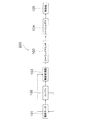
図1に示すように、自動二輪車用動力伝達システム200は、電動モータ101と、エンジン102と、無段変速機103と、ツーウェイクラッチ100と、ファイナルギヤ104と、駆動輪105とを備えている。
[Power transmission system for motorcycles]
As shown in FIG. 1, the
[電動モータ]
電動モータ101は、本実施形態に係る自動二輪車の駆動源の1つである。電動モータ101は、発進時や急加速時などにおいて駆動輪105を回転駆動させる。また、電動モータ101は、エンジン102を始動させるように構成されている。すなわち、電動モータ101は、エンジン102の始動時においてセルモータとして使用される。また、電動モータ101は、エンジン102によって駆動されて発電するように構成される。すなわち、電動モータ101は、エンジン102の始動後において、ダイナモとしても使用される。
[Electric motor]
The
[エンジン]
エンジン102は、本実施形態に係る自動二輪車の駆動源の1つである。すなわち、本実施形態に係る自動二輪車は、電動モータ101とエンジン102との2つの駆動源を有している。エンジン102は、通常走行時において、駆動輪105を回転駆動させる。また、エンジン102は、駆動輪105を回転駆動させるとともに、電動モータ101を駆動して発電させている。
[engine]
The
[無段変速機]
無段変速機103は、電動モータ101及びエンジン102からのトルクを変速するように構成されている。無段変速機103は、ベルト式無段変速機である。すなわち、本実施形態に係る自動二輪車は、オートマチックトランスミッションを採用している。無段変速機103は、電動モータ101及びエンジン102からのトルクが入力される。
[Continuous variable transmission]
The continuously
無段変速機103は、駆動側プーリ装置と、従動側プーリ装置と、ベルトとを有している。ベルトは、駆動側プーリ装置と従動側プーリ装置との間に架かっている。各プーリ装置の径が変わることによって、変速比が連続的に変化する。
The continuously
[ツーウェイクラッチ]
ツーウェイクラッチ100は、無段変速機103と駆動輪105との間に配置されている。詳細には、ツーウェイクラッチ100は、無段変速機103とファイナルギヤ104との間に配置されている。ツーウェイクラッチ100は、無段変速機103からのトルクを駆動輪105に伝達するとともに、停車中は駆動輪105から無段変速機103へのトルク伝達を遮断するように構成されている。なお、ツーウェイクラッチ100の詳細については後述する。
[Two-way clutch]
The two-
[ファイナルギヤ]
ファイナルギヤ104は、ツーウェイクラッチ100と駆動輪105との間に配置されている。具体的には、ファイナルギヤ104は、ドライブシャフト(図示省略)と駆動輪105との間に設けられている。ファイナルギヤ104は、例えば、平歯車、又ははすば歯車を組み合わせた3軸の減速機構や、遊星歯車を用いた1軸の減速機構が挙げられる。
[Final gear]
The
[駆動輪]
駆動輪105は、電動モータ101及びエンジン102からのトルクを受けて回転する車輪である。自動二輪車では、一般的に、後輪が駆動輪105である。
[Driving wheel]
The
[自動二輪車用動力伝達システムの動作]
上述したように構成された自動二輪車用動力伝達システム200は、以下のように動作する。
[Operation of power transmission system for motorcycles]
The motorcycle
発進時、及び低中速走行時は、電動モータ101によって、駆動輪105を駆動する。すなわち、電動モータ101からのトルクが、無段変速機103、ツーウェイクラッチ100、及びファイナルギヤ104を介して駆動輪105に伝達される。
The
次に、通常走行時は、エンジン102からのトルクによって、駆動輪105を駆動する。すなわち、エンジン102からのトルクが、無段変速機103、ツーウェイクラッチ100、及びファイナルギヤ104を介して駆動輪105に伝達される。なお、エンジン102のトルクによって、電動モータ101を発電させてもよい。すなわち、電動モータ101をダイナモとして機能させる。電動モータ101によって生成された電力は図示しないバッテリに蓄えられる。なお、エンジン102は、電動モータ101によって始動させられる。すなわち、電動モータ101は、セルモータとして機能する。
Next, during normal driving, the
このように、ツーウェイクラッチ100は、電動モータ101及びエンジン102からのトルクを駆動輪105へと伝達する。なお、後述するように、ツーウェイクラッチ100は、増速時及び減速時において、電動モータ101及びエンジン102からのトルクを駆動輪105へ伝達する。
In this way, the two-way clutch 100 transmits the torque from the
次に、停車中において自動二輪車を押して移動させる場合、駆動輪105からのトルク伝達は、ツーウェイクラッチ100によって遮断される。すなわち、駆動輪105のトルクによって、エンジン102は回転しない。このため、停車中において自動二輪車を容易に移動させることができる。
Next, when the motorcycle is pushed and moved while the vehicle is stopped, the torque transmission from the
[ツーウェイクラッチの詳細]
上述したツーウェイクラッチ100の詳細について図面を参照しつつ説明する。なお、以下の説明において、軸方向とは、ツーウェイクラッチの回転軸Oが延びる方向を意味する。また、半径方向とは、回転軸Oを中心とした円の半径方向を意味し、周方向とは、回転軸Oを中心とした円の周方向を意味する。また、半径方向の内側とは、半径方向において回転軸Oに近い側を意味し、半径方向の外側とは、半径方向において回転軸Oから遠い側を意味する。
[Details of two-way clutch]
The details of the two-way clutch 100 described above will be described with reference to the drawings. In the following description, the axial direction means the direction in which the rotation axis O of the two-way clutch extends. The radial direction means the radial direction of the circle centered on the rotation axis O, and the circumferential direction means the circumferential direction of the circle centered on the rotation axis O. Further, the inner side in the radial direction means the side close to the rotation axis O in the radial direction, and the outer side in the radial direction means the side far from the rotation axis O in the radial direction.
図2及び図3に示すように、ツーウェイクラッチ100は、アウターレース1、インナーボディ2、複数のローラ3、複数対の付勢部材4、ホルダ5、及びカム機構6を備えている。アウターレース1が駆動輪105側と接続されており、インナーボディ2が電動モータ101及びエンジン102側と接続されている。
As shown in FIGS. 2 and 3, the two-
[アウターレース]
アウターレース1は、筒状である。アウターレース1は、駆動輪105へとトルクを出力する。アウターレース1は、回転軸Oを中心に回転可能である。アウターレース1は、例えば、機械構造用炭素鋼、機械構造用工具鋼、炭素工具鋼、又は合金工具鋼などによって形成されている。
[Outer race]
The
図4に示すように、アウターレース1は、円板部11と、筒状部12とを有している。
筒状部12は、円筒状であって、円板部11の外周縁から軸方向に延びている。この筒状部12は、ツーウェイクラッチ100の外壁を構成している。
As shown in FIG. 4, the
The
[インナーボディ]
図2及び図3に示すように、インナーボディ2は、半径方向においてアウターレース1の内側に配置されている。詳細には、インナーボディ2は、半径方向においてアウターレース1の筒状部12の内側に配置されている。インナーボディ2は、回転軸Oを中心に回転可能である。また、インナーボディ2は、アウターレース1に対して、相対回転可能である。インナーボディ2は、電動モータ101又はエンジン102からのトルクが入力される。
[Inner body]
As shown in FIGS. 2 and 3, the
図5に示すように、インナーボディ2は、インナーボディ本体部21と、ボス部22とを有している。インナーボディ2は、例えば、機械構造用炭素鋼、機械構造用工具鋼、炭素工具鋼、又は合金工具鋼などによって形成されている。
As shown in FIG. 5, the
インナーボディ本体部21は、円板状である。インナーボディ本体部21の外周面211は、アウターレース1の内周面と間隔をあけて配置されている。ローラ3、付勢部材4,及びホルダ5を取り除いた状態において、インナーボディ本体部21の外周面211は、アウターレース1の内周面と対向している。なお、アウターレース1の内周面とは、アウターレース1の筒状部12の内周面を意味する。
The inner body
インナーボディ本体部21の外周面211には、複数のカム面212が形成されている。各カム面212は、周方向において間隔をあけて形成されている。好ましくは、各カム面212は、周方向において、等間隔に配置されている。
A plurality of cam surfaces 212 are formed on the outer
各カム面212は、半径方向において内側に凹むように構成されている。カム面212の周方向の中央部が最もアウターレース1の内周面から離れている。また、各カム面212は、周方向の両端部に近付くにつれて、アウターレース1に近付くように構成されている。具体的には、各カム面212は、軸方向視において、円弧状に形成されている。
Each
また、インナーボディ本体部21は、複数の第1貫通孔213を有している。各第1貫通孔213は、インナーボディ本体部21を軸方向に貫通している。各第1貫通孔213は、周方向において間隔をあけて配置されている。好ましくは、各第1貫通孔213は、周方向において等間隔に配置されている。各第1貫通孔213は、同一の円周上に配置されている。各第1貫通孔213は、周方向に延びる長孔形状である。
Further, the inner body
ボス部22は、円筒状であって、インナーボディ本体部21から軸方向に延びている。ボス部22は、インナーボディ本体部21と同軸上に配置されている。ボス部22は、電動モータ101又はエンジン102側からのトルクが入力される入力軸(図示省略)と係合するように構成されている。詳細には、ボス部22は、第2貫通孔221を有している。第2貫通孔221は、入力軸が係合されるように構成されている。例えば、第2貫通孔221は、内周面において、対向する一対の平面を有している。そして、入力軸は、外周面において対向する一対の平面を有している。この構成によって、入力軸は、第2貫通孔221と係合して一体的に回転可能となる。なお、第2貫通孔221は、ボス部22のみならず、インナーボディ本体部21も貫通している。
The
[ホルダ]
図2及び図3に示すように、ホルダ5は、各ローラ3及び各付勢部材4を保持している。ホルダ5は、インナーボディ2と相対回転可能に配置されている。ホルダ5は、樹脂製であり、具体的には、PA系樹脂、POM系樹脂、PPS系樹脂、PBT系樹脂、PEEK樹脂、又はPTFE系樹脂などによって形成することができる。ホルダ5は、軸方向において、インナーボディ2と並んでいる。
[holder]
As shown in FIGS. 2 and 3, the
図6に示すように、ホルダ5は、円板プレート状であって、その中央部に第3貫通孔51を有している。ホルダ5は、ホルダ本体部52と、保持部53とを有している。ホルダ本体部52は、円板状であって、中央部に第3貫通孔51を有している。第3貫通孔51は、軸方向において、ホルダ本体部52を貫通している。また、第3貫通孔51は、軸方向視において、円形である。
As shown in FIG. 6, the
ホルダ5の第3貫通孔51内を、インナーボディ2のボス部22が貫通している。すなわち、ボス部22は、第3貫通孔51を介して、ホルダ5を越えて軸方向に延びている。ボス部22の外径は、第3貫通孔51の内径よりも小さい。ホルダ5は、第3貫通孔51の内周面がボス部22の外周面と当接することによって、インナーボディ2に支持されている。具体的には、第3貫通孔51の内周面の上端部と、ボス部22の外周面の上端部とが、接触している。
The
ホルダ本体部52は、複数の第4貫通孔521を有している。各第4貫通孔521は、周方向に互いに間隔をあけて配置されている。好ましくは、各第4貫通孔521は、週方向において等間隔に配置されている。
The holder
保持部53は、周方向において、ローラ3及び付勢部材4を保持するように構成されている。保持部53は、円筒状であって、ホルダ本体部52から軸方向に延びている。保持部53は、半径方向において、アウターレース1とインナーボディ2との間に配置されている。詳細には、保持部53は、半径方向において、アウターレース1の筒状部12と、インナーボディ2のインナーボディ本体部21との間に配置されている。
The holding
保持部53は、複数の第5貫通孔531を有している。各第5貫通孔531は、半径方向において、保持部53を貫通している。このため、ローラ3と一対の付勢部材4とを取り除いた状態において、この第5貫通孔531を介して、アウターレース1とインナーボディ2とが対向する。各第5貫通孔531は、周方向に間隔をあけて配置されている。好ましくは、各第5貫通孔531は、周方向に等間隔に配置されている。
The holding
各第5貫通孔531は、一対の内壁面によって構成されている。この一対の内壁面は、保持面532を構成している。ローラ3及び一対の付勢部材4を取り除いた状態において、一対の保持面532は、周方向において対向している。この一対の保持面532は、ローラ3及び一対の付勢部材4を保持する。
Each fifth through
[ローラ]
図2及び図3に示すように、ローラ3は、ホルダ5に保持されている。詳細には、ローラ3は、一対の付勢部材4を介して、ホルダ5に保持されている。ローラ3は、ホルダ5の第5貫通孔531内に配置されている。
[roller]
As shown in FIGS. 2 and 3, the
各ローラ3は、軸方向に延びる円筒状である。ローラ3は、半径方向において、アウターレース1とインナーボディ2との間に配置されている。詳細には、ローラ3は、半径方向において、アウターレース1の筒状部12と、インナーボディ本体部21との間に配置されている。
Each
ローラ3は、中立位置と、噛合位置とを取り得る。図7に示すように、中立位置とは、ローラ3がアウターレース1とインナーボディ2との間で噛合わない位置を意味する。具体的には、ローラ3は、中立位置に位置しているとき、周方向においてカム面212の中央部に位置している。
The
図8又は図9に示すように、噛合位置とは、ローラ3がアウターレース1とインナーボディ2との間で噛合っている位置を意味する。具体的には、ローラ3は、噛合位置に位置しているとき、カム面212の中央部から両端部に移動した位置に位置している。
As shown in FIG. 8 or 9, the meshing position means a position where the
[付勢部材]
図2及び図3に示すように、複数対の付勢部材4は第5貫通孔531内に配置されている。複数対の付勢部材4は、それぞれローラ3を周方向から挟んでインナーボディ2側に付勢するように構成されている。すなわち、各付勢部材4は、第1端部と第2端部とを有している。そして、ローラ3と接触する第1端部は、保持面532と接触する第2端部よりも半径方向において内側に配置されている。各付勢部材4は、ホルダ5によって保持されている。付勢部材4は、例えば、板バネであってもよいし、コイルスプリングであってもよい。
[Biasing member]
As shown in FIGS. 2 and 3, a plurality of pairs of urging
[カム機構]
カム機構6は、インナーボディ2がホルダ5と相対回転したときに、ローラ3をアウターレース1とインナーボディ2との間で噛ませるように構成されている。具体的には、カム機構6は、インナーボディ2の外周面に形成されたカム面212を有する。
[Cam mechanism]
The
[ツーウェイクラッチの動作]
上述したように構成されたツーウェイクラッチ100は、以下のように動作する。まず、電動モータ101又はエンジン102などの駆動源からトルクが入力されていない状態では、図7に示すように、ローラ3は中立位置に位置している。すなわち、ローラ3は、カム面212の中央部に位置しており、アウターレース1とインナーボディ2との間で噛合っていない。このため、例えば、停車している自動二輪車を押して移動させたい場合、自動二輪車を押すことによって駆動輪105が回転しても、アウターレース1のみが回転し、インナーボディ2は回転しないため、電動モータ101又はエンジン102を回転させることがない。すなわち、ツーウェイクラッチ100によって、駆動輪105から無段変速機103へのトルク伝達を遮断する。この結果、容易に自動二輪車を移動させることができる。なお、図7の矢印は、アウターレース1の回転方向を示す。
[Operation of two-way clutch]
The two-way clutch 100 configured as described above operates as follows. First, as shown in FIG. 7, the
次に、電動モータ101又はエンジン102からトルクが入力されると、インナーボディ2が回転する。ここで、ホルダ5は慣性によってインナーボディ2よりも回転速度が遅くなるため、インナーボディ2とホルダ5とが相対的に回転する。すると、図8に示すように、ローラ3が中立位置から噛合位置に移動し、ローラ3がアウターレース1とインナーボディ2との間で噛合う。この結果、アウターレース1とインナーボディ2とは一体的に回転する。すなわち、インナーボディ2から各ローラ3を介してアウターレース1へとトルクが伝達される。したがって、ツーウェイクラッチ100は、無段変速機103からのトルクを駆動輪105へと伝達する。なお、図8の矢印は、ツーウェイクラッチ100の回転方向を示す。
Next, when torque is input from the
また、減速時においてホルダ5は慣性によってインナーボディ2よりも回転速度が速くなるため、インナーボディ2とホルダ5とが相対的に回転する。すると、図9に示すように、ローラ3が中立位置から噛合位置に移動し、ローラ3がアウターレース1とインナーボディ2との間で噛合う。この結果、アウターレース1とインナーボディ2とは一体的に回転する。すなわち、インナーボディ2から各ローラ3を介してアウターレース1へとトルクが伝達される。したがって、ツーウェイクラッチ100は、無段変速機103からのトルクを駆動輪105へと伝達する。なお、図9の矢印は、ツーウェイクラッチ100の回転方向を示す。
Further, during deceleration, the
以上のように、電動モータ101又はエンジン102が増速又は減速したとき、ホルダ5の慣性によって、インナーボディ2とホルダ5とが相対回転する。その結果、ローラ3がアウターレース1とインナーボディ2との間で噛合い、電動モータ101又はエンジン102からのトルクが駆動輪105へと伝達される。
As described above, when the
ホルダ5の慣性質量が大きいほど、増速時及び減速時においてインナーボディ2とホルダ5とをより確実に相対回転させることができる。よって、ホルダ5の慣性質量を大きくするため、本実施形態では、ホルダ5の体積を大きくしている。具体的には、ホルダ5のホルダ本体部52を、ボス部22からアウターレース1まで延びる円板のプレート状としている。
The larger the inertial mass of the
また、インナーボディ2とホルダ5との摺動抵抗をより小さくしてインナーボディ2とホルダ5とをより確実に相対回転させるために、インナーボディ2とホルダ5との接触点を半径方向の内側に持ってきている。具体的には、インナーボディ2のボス部22とホルダ5の第3貫通孔51の内周面とで接触させている。
Further, in order to reduce the sliding resistance between the
[変形例]
以上、本発明の実施形態について説明したが、本発明はこれらに限定されるものではなく、本発明の趣旨を逸脱しない限りにおいて種々の変更が可能である。
[Modification example]
Although the embodiments of the present invention have been described above, the present invention is not limited thereto, and various modifications can be made without departing from the spirit of the present invention.
例えば、上記実施形態において、ツーウェイクラッチ100は、無段変速機103とファイナルギヤ104との間に配置されているが、ツーウェイクラッチ100の配置はこれに限定されない。例えば、図10に示すように、ツーウェイクラッチ100は、駆動輪105とファイナルギヤ104との間に配置されていてもよい。
For example, in the above embodiment, the two-
また、上記実施形態のツーウェイクラッチ100では、軸方向視において、カム面212は円弧状に形成されているが、カム面212はV字状に形成されていてもよいし、他の形状に形成されていてもよい。
Further, in the two-
また、ツーウェイクラッチ100において、エンジンからのトルクをインナーボディ2に入力するための入力軸と、ボス部22の第2貫通孔221とは、スプライン嵌合やその他の構造で係合していてもよい。
Further, in the two-
また、インナーボディ本体部21は、第1貫通孔213を有していなくてもよい。同様に、ホルダ5は、第4貫通孔521を有していなくてもよい。
Further, the inner body
また、上記実施形態では、ハイブリッド式の自動二輪車に自動二輪車用動力伝達システムを適用しているが、電動式の自動二輪車にも適用してもよい。 Further, in the above embodiment, the power transmission system for a motorcycle is applied to a hybrid motorcycle, but it may also be applied to an electric motorcycle.
100 ツーウェイクラッチ
101 電動モータ
102 エンジン
103 無段変速機
104 ファイナルギヤ
105 駆動輪
200 自動二輪車用動力伝達システム
100 Two-way clutch 101
Claims (9)
駆動輪と、
前記電動モータからのトルクを変速する無段変速機と、
前記無段変速機と前記駆動輪との間に配置され、増速したとき及び減速したときに前記無段変速機からのトルクを前記駆動輪に伝達するとともに、停車中において前記駆動輪から前記無段変速機へのトルク伝達を遮断するように構成されたツーウェイクラッチと、
を備える、
自動二輪車用動力伝達システム。
With an electric motor
With the drive wheels
A continuously variable transmission that shifts the torque from the electric motor,
It is arranged between the continuously variable transmission and the drive wheels, and when the speed is increased or decelerated, the torque from the continuously variable transmission is transmitted to the drive wheels, and the drive wheels provide the torque while the vehicle is stopped. A two-way clutch configured to cut off torque transmission to the continuously variable transmission,
To prepare
Power transmission system for motorcycles.
前記ツーウェイクラッチは、前記無段変速機と前記ファイナルギヤとの間に配置される、
請求項1に記載の自動二輪車用動力伝達システム。
Further provided with a final gear arranged between the continuously variable transmission and the drive wheels.
The two-way clutch is arranged between the continuously variable transmission and the final gear.
The power transmission system for a motorcycle according to claim 1.
前記ツーウェイクラッチは、前記駆動輪と前記ファイナルギヤとの間に配置される、
請求項1に記載の自動二輪車用動力伝達システム。
Further provided with a final gear arranged between the continuously variable transmission and the drive wheels.
The two-way clutch is arranged between the drive wheels and the final gear.
The power transmission system for a motorcycle according to claim 1.
請求項1から3のいずれかに記載の自動二輪車用動力伝達システム。
The continuously variable transmission is a belt-type continuously variable transmission.
The power transmission system for a motorcycle according to any one of claims 1 to 3.
請求項1から4のいずれかに記載の自動二輪車用動力伝達システム。
The electric motor is configured to be driven by an engine to generate electricity and to start the engine.
The power transmission system for a motorcycle according to any one of claims 1 to 4.
前記無段変速機は、前記エンジンからのトルクを変速する、
請求項1から5のいずれかに記載の自動二輪車用動力伝達システム。
With more engines
The continuously variable transmission shifts the torque from the engine.
The power transmission system for a motorcycle according to any one of claims 1 to 5.
筒状のアウターレースと、
半径方向において前記アウターレースの内側に配置されるインナーボディと、
半径方向において、前記アウターレースと前記インナーボディとの間に配置されるローラと、
前記インナーボディと相対回転可能に配置され、前記ローラを保持するホルダと、
前記インナーボディが前記ホルダと相対回転したときに、前記ローラを前記アウターレースと前記インナーボディとの間で噛ませるカム機構と、
を有する、
請求項1から6のいずれかに記載の自動二輪車用動力伝達システム。
The two-way clutch
Cylindrical outer lace and
An inner body arranged inside the outer race in the radial direction,
A roller arranged between the outer race and the inner body in the radial direction,
A holder that is rotatably arranged relative to the inner body and holds the roller,
A cam mechanism that engages the roller between the outer race and the inner body when the inner body rotates relative to the holder.
Have,
The power transmission system for a motorcycle according to any one of claims 1 to 6.
円板状であって中央部に第3貫通孔を有するホルダ本体部と、 A holder body that is disk-shaped and has a third through hole in the center,
前記ホルダ本体部から軸方向に延び、半径方向において、前記アウターレースと前記インナーボディとの間に配置されて前記ローラを保持するように構成された保持部と、 A holding portion extending axially from the holder main body portion and arranged between the outer race and the inner body in the radial direction to hold the roller.
を有し、Have,
前記インナーボディは、前記第3貫通孔内を貫通するボス部を有する、 The inner body has a boss portion that penetrates the inside of the third through hole.
請求項7に記載の自動二輪車用動力伝達システム。The power transmission system for a motorcycle according to claim 7.
請求項7又は8に記載の自動二輪車用動力伝達システム。The power transmission system for a motorcycle according to claim 7 or 8.
Priority Applications (2)
| Application Number | Priority Date | Filing Date | Title |
|---|---|---|---|
| JP2017049772A JP6892766B2 (en) | 2017-03-15 | 2017-03-15 | Power transmission system for motorcycles |
| PCT/JP2018/009743 WO2018168854A1 (en) | 2017-03-15 | 2018-03-13 | Automatic two-wheeled vehicle motive-force transmission system |
Applications Claiming Priority (1)
| Application Number | Priority Date | Filing Date | Title |
|---|---|---|---|
| JP2017049772A JP6892766B2 (en) | 2017-03-15 | 2017-03-15 | Power transmission system for motorcycles |
Publications (3)
| Publication Number | Publication Date |
|---|---|
| JP2018150020A JP2018150020A (en) | 2018-09-27 |
| JP2018150020A5 JP2018150020A5 (en) | 2019-09-12 |
| JP6892766B2 true JP6892766B2 (en) | 2021-06-23 |
Family
ID=63523172
Family Applications (1)
| Application Number | Title | Priority Date | Filing Date |
|---|---|---|---|
| JP2017049772A Active JP6892766B2 (en) | 2017-03-15 | 2017-03-15 | Power transmission system for motorcycles |
Country Status (2)
| Country | Link |
|---|---|
| JP (1) | JP6892766B2 (en) |
| WO (1) | WO2018168854A1 (en) |
Family Cites Families (8)
| Publication number | Priority date | Publication date | Assignee | Title |
|---|---|---|---|---|
| KR100258784B1 (en) * | 1998-01-20 | 2000-06-15 | 마재열 | Power changing apparatus of bicycle hub |
| JP4037952B2 (en) * | 1998-03-16 | 2008-01-23 | ヤマハ発動機株式会社 | Electric motorcycle |
| JP3083513B1 (en) * | 1999-03-18 | 2000-09-04 | 白光 廖 | Power transmission system |
| JP2001008314A (en) * | 1999-06-15 | 2001-01-12 | Yamaha Motor Co Ltd | Drive controller of motor-driven vehicle |
| JP4248941B2 (en) * | 2003-06-09 | 2009-04-02 | 本田技研工業株式会社 | Hybrid vehicle |
| JP3967308B2 (en) * | 2003-09-29 | 2007-08-29 | 本田技研工業株式会社 | Hybrid vehicle |
| CN101157374A (en) * | 2007-10-30 | 2008-04-09 | 西安交通大学 | Mixed dynamical motorcycle |
| GB2487933A (en) * | 2011-02-08 | 2012-08-15 | Scion Sprays Ltd | Hybrid drive system |
-
2017
- 2017-03-15 JP JP2017049772A patent/JP6892766B2/en active Active
-
2018
- 2018-03-13 WO PCT/JP2018/009743 patent/WO2018168854A1/en active Application Filing
Also Published As
| Publication number | Publication date |
|---|---|
| WO2018168854A1 (en) | 2018-09-20 |
| JP2018150020A (en) | 2018-09-27 |
Similar Documents
| Publication | Publication Date | Title |
|---|---|---|
| JP6660876B2 (en) | Continuously variable transmission | |
| WO2013069098A1 (en) | Power transmission device for vehicle | |
| JP6792585B2 (en) | Power transmission device and motorcycle | |
| JP6100388B2 (en) | Torque cam device and belt-type continuously variable transmission | |
| JP5304454B2 (en) | Drive device for hybrid vehicle | |
| JP6892766B2 (en) | Power transmission system for motorcycles | |
| KR101675383B1 (en) | Dual one way clutch and transmission having the same | |
| JP4566230B2 (en) | Drive device | |
| JP5282761B2 (en) | Two-way clutch and vehicle drive device | |
| JP2015031312A (en) | Power transmission mechanism | |
| JP6000178B2 (en) | Vehicle transmission | |
| JP6861659B2 (en) | Clutch device | |
| JP6791591B2 (en) | Torque cam device and continuously variable transmission | |
| JP2009078754A (en) | Method for controlling driving force transmission device for hybrid vehicle | |
| JP2020005441A (en) | Driving motor and electric vehicle | |
| JP5942877B2 (en) | Control device for belt type continuously variable transmission | |
| JP6575377B2 (en) | Continuously variable transmission | |
| JP2010179858A (en) | Transmission system for hybrid vehicle | |
| JP5663370B2 (en) | Continuously variable transmission for vehicle | |
| CN110654495B (en) | Driving motor and electric vehicle | |
| JP6575375B2 (en) | Continuously variable transmission | |
| JP6447065B2 (en) | Continuously variable transmission | |
| JP6060598B2 (en) | Driving force distribution device | |
| JP5799684B2 (en) | Power transmission device | |
| JP2021162112A (en) | Dynamic damper device |
Legal Events
| Date | Code | Title | Description |
|---|---|---|---|
| A621 | Written request for application examination |
Free format text: JAPANESE INTERMEDIATE CODE: A621 Effective date: 20190319 |
|
| A521 | Written amendment |
Free format text: JAPANESE INTERMEDIATE CODE: A523 Effective date: 20190802 |
|
| A131 | Notification of reasons for refusal |
Free format text: JAPANESE INTERMEDIATE CODE: A131 Effective date: 20200512 |
|
| A521 | Written amendment |
Free format text: JAPANESE INTERMEDIATE CODE: A523 Effective date: 20200604 |
|
| A131 | Notification of reasons for refusal |
Free format text: JAPANESE INTERMEDIATE CODE: A131 Effective date: 20201117 |
|
| A521 | Written amendment |
Free format text: JAPANESE INTERMEDIATE CODE: A523 Effective date: 20201216 |
|
| TRDD | Decision of grant or rejection written | ||
| A01 | Written decision to grant a patent or to grant a registration (utility model) |
Free format text: JAPANESE INTERMEDIATE CODE: A01 Effective date: 20210525 |
|
| A61 | First payment of annual fees (during grant procedure) |
Free format text: JAPANESE INTERMEDIATE CODE: A61 Effective date: 20210528 |
|
| R150 | Certificate of patent or registration of utility model |
Ref document number: 6892766 Country of ref document: JP Free format text: JAPANESE INTERMEDIATE CODE: R150 |