JP6892384B2 - On-demand system information - Google Patents
On-demand system information Download PDFInfo
- Publication number
- JP6892384B2 JP6892384B2 JP2017541634A JP2017541634A JP6892384B2 JP 6892384 B2 JP6892384 B2 JP 6892384B2 JP 2017541634 A JP2017541634 A JP 2017541634A JP 2017541634 A JP2017541634 A JP 2017541634A JP 6892384 B2 JP6892384 B2 JP 6892384B2
- Authority
- JP
- Japan
- Prior art keywords
- base station
- system information
- module
- request
- signal
- Prior art date
- Legal status (The legal status is an assumption and is not a legal conclusion. Google has not performed a legal analysis and makes no representation as to the accuracy of the status listed.)
- Active
Links
- 238000000034 method Methods 0.000 claims description 308
- 230000005540 biological transmission Effects 0.000 claims description 305
- 238000004891 communication Methods 0.000 claims description 280
- 230000006854 communication Effects 0.000 claims description 280
- 238000004590 computer program Methods 0.000 claims description 2
- 230000000737 periodic effect Effects 0.000 description 171
- 238000012545 processing Methods 0.000 description 97
- 238000010586 diagram Methods 0.000 description 69
- 230000006870 function Effects 0.000 description 69
- 230000004044 response Effects 0.000 description 69
- 238000007726 management method Methods 0.000 description 43
- 230000008685 targeting Effects 0.000 description 26
- 230000001788 irregular Effects 0.000 description 24
- 230000006399 behavior Effects 0.000 description 21
- 230000004048 modification Effects 0.000 description 19
- 238000012986 modification Methods 0.000 description 19
- 230000001360 synchronised effect Effects 0.000 description 19
- 238000012937 correction Methods 0.000 description 16
- 230000008569 process Effects 0.000 description 15
- 230000008859 change Effects 0.000 description 13
- 238000005516 engineering process Methods 0.000 description 12
- 230000011664 signaling Effects 0.000 description 11
- 230000008054 signal transmission Effects 0.000 description 10
- 238000012544 monitoring process Methods 0.000 description 8
- 239000000969 carrier Substances 0.000 description 6
- 241000700159 Rattus Species 0.000 description 5
- 230000008901 benefit Effects 0.000 description 5
- 238000003491 array Methods 0.000 description 4
- 230000003287 optical effect Effects 0.000 description 4
- 101100490659 Arabidopsis thaliana AGP17 gene Proteins 0.000 description 3
- 101100049938 Neurospora crassa (strain ATCC 24698 / 74-OR23-1A / CBS 708.71 / DSM 1257 / FGSC 987) exr-1 gene Proteins 0.000 description 3
- 101150039363 SIB2 gene Proteins 0.000 description 3
- 101100027103 Saccharomyces cerevisiae (strain ATCC 204508 / S288c) NUP133 gene Proteins 0.000 description 3
- 238000007792 addition Methods 0.000 description 3
- 230000002776 aggregation Effects 0.000 description 3
- 238000004220 aggregation Methods 0.000 description 3
- 230000008520 organization Effects 0.000 description 3
- 101150101384 rat1 gene Proteins 0.000 description 3
- 238000012546 transfer Methods 0.000 description 3
- 230000007704 transition Effects 0.000 description 3
- 230000007175 bidirectional communication Effects 0.000 description 2
- 239000000835 fiber Substances 0.000 description 2
- 230000007774 longterm Effects 0.000 description 2
- 230000003595 spectral effect Effects 0.000 description 2
- 230000001960 triggered effect Effects 0.000 description 2
- 230000002457 bidirectional effect Effects 0.000 description 1
- 230000001413 cellular effect Effects 0.000 description 1
- 239000003795 chemical substances by application Substances 0.000 description 1
- 238000001514 detection method Methods 0.000 description 1
- 230000000694 effects Effects 0.000 description 1
- 230000002349 favourable effect Effects 0.000 description 1
- 239000006249 magnetic particle Substances 0.000 description 1
- 238000005259 measurement Methods 0.000 description 1
- 238000010295 mobile communication Methods 0.000 description 1
- 239000003607 modifier Substances 0.000 description 1
- 239000002245 particle Substances 0.000 description 1
- 229920001690 polydopamine Polymers 0.000 description 1
- 238000013468 resource allocation Methods 0.000 description 1
- 230000011218 segmentation Effects 0.000 description 1
- 238000001228 spectrum Methods 0.000 description 1
- 239000002699 waste material Substances 0.000 description 1
Images


Classifications
-
- H—ELECTRICITY
- H04—ELECTRIC COMMUNICATION TECHNIQUE
- H04W—WIRELESS COMMUNICATION NETWORKS
- H04W36/00—Hand-off or reselection arrangements
- H04W36/0005—Control or signalling for completing the hand-off
- H04W36/0083—Determination of parameters used for hand-off, e.g. generation or modification of neighbour cell lists
-
- H—ELECTRICITY
- H04—ELECTRIC COMMUNICATION TECHNIQUE
- H04W—WIRELESS COMMUNICATION NETWORKS
- H04W48/00—Access restriction; Network selection; Access point selection
- H04W48/08—Access restriction or access information delivery, e.g. discovery data delivery
- H04W48/12—Access restriction or access information delivery, e.g. discovery data delivery using downlink control channel
-
- H—ELECTRICITY
- H04—ELECTRIC COMMUNICATION TECHNIQUE
- H04B—TRANSMISSION
- H04B7/00—Radio transmission systems, i.e. using radiation field
- H04B7/02—Diversity systems; Multi-antenna system, i.e. transmission or reception using multiple antennas
- H04B7/04—Diversity systems; Multi-antenna system, i.e. transmission or reception using multiple antennas using two or more spaced independent antennas
- H04B7/0413—MIMO systems
-
- H—ELECTRICITY
- H04—ELECTRIC COMMUNICATION TECHNIQUE
- H04L—TRANSMISSION OF DIGITAL INFORMATION, e.g. TELEGRAPHIC COMMUNICATION
- H04L12/00—Data switching networks
- H04L12/02—Details
- H04L12/16—Arrangements for providing special services to substations
- H04L12/18—Arrangements for providing special services to substations for broadcast or conference, e.g. multicast
-
- H—ELECTRICITY
- H04—ELECTRIC COMMUNICATION TECHNIQUE
- H04W—WIRELESS COMMUNICATION NETWORKS
- H04W48/00—Access restriction; Network selection; Access point selection
- H04W48/08—Access restriction or access information delivery, e.g. discovery data delivery
- H04W48/14—Access restriction or access information delivery, e.g. discovery data delivery using user query or user detection
-
- Y—GENERAL TAGGING OF NEW TECHNOLOGICAL DEVELOPMENTS; GENERAL TAGGING OF CROSS-SECTIONAL TECHNOLOGIES SPANNING OVER SEVERAL SECTIONS OF THE IPC; TECHNICAL SUBJECTS COVERED BY FORMER USPC CROSS-REFERENCE ART COLLECTIONS [XRACs] AND DIGESTS
- Y02—TECHNOLOGIES OR APPLICATIONS FOR MITIGATION OR ADAPTATION AGAINST CLIMATE CHANGE
- Y02D—CLIMATE CHANGE MITIGATION TECHNOLOGIES IN INFORMATION AND COMMUNICATION TECHNOLOGIES [ICT], I.E. INFORMATION AND COMMUNICATION TECHNOLOGIES AIMING AT THE REDUCTION OF THEIR OWN ENERGY USE
- Y02D30/00—Reducing energy consumption in communication networks
- Y02D30/70—Reducing energy consumption in communication networks in wireless communication networks
Description
相互参照
本特許出願は、各々が本出願の譲受人に譲渡された、2015年7月20日に出願された、「On-Demand System Information」と題する、Kubotaらによる米国特許出願第14/803,793号、2015年2月26日に出願された、「Service Based System Information Acquisition」と題する、Hornらによる米国仮特許出願第62/121,326号、および2015年2月10日に出願された、「On-Demand System Information」と題する、Kubotaらによる米国仮特許出願第62/114,157号の優先権を主張する。
Mutual Reference This patent application is filed on July 20, 2015, each assigned to the assignee of this application, entitled "On-Demand System Information", US Patent Application No. 14 / 803,793 by Kubota et al. No., US Provisional Patent Application No. 62 / 121,326 by Horn et al., Filed February 26, 2015, entitled "Service Based System Information Acquisition," and filed February 10, 2015, "On. -Claims the priority of US Provisional Patent Application No. 62 / 114,157 by Kubota et al., entitled "Demand System Information".
本開示は、たとえば、ワイヤレス通信システムに関し、より詳細には、ユーザ機器(UE)中心ネットワークを有するワイヤレス通信システムなどの、ワイヤレス通信システムにおけるオンデマンドシステム情報の送信に関する。 The present disclosure relates to, for example, wireless communication systems, and more particularly to transmission of on-demand system information in wireless communication systems, such as wireless communication systems having a user equipment (UE) -centric network.
ワイヤレス通信システムは、音声、ビデオ、パケットデータ、メッセージング、ブロードキャストなどの様々なタイプの通信コンテンツを提供するために広く展開されている。これらのシステムは、利用可能なシステムリソース(たとえば、時間、周波数、および電力)を共有することによって複数のユーザとの通信をサポートすることが可能な多元接続システムであり得る。そのような多元接続システムの例には、符号分割多元接続(CDMA)システム、時分割多元接続(TDMA)システム、周波数分割多元接続(FDMA)システム、および直交周波数分割多元接続(OFDMA)システムがある。 Wireless communication systems are widely deployed to provide various types of communication content such as voice, video, packet data, messaging, and broadcast. These systems can be multiple access systems that can support communication with multiple users by sharing available system resources (eg, time, frequency, and power). Examples of such multiple access systems include code division multiple access (CDMA) systems, time division multiple access (TDMA) systems, frequency division multiple access (FDMA) systems, and orthogonal frequency division multiple access (OFDMA) systems. ..
例として、ワイヤレス多元接続通信システムは、ユーザ機器(UE)としても知られている複数の通信デバイスのための通信を各々が同時にサポートする、いくつかの基地局を含み得る。基地局は、ダウンリンクチャネル(たとえば、基地局からUEへの送信用)およびアップリンクチャネル(たとえば、UEから基地局への送信用)上でUEと通信し得る。 As an example, a wireless multiple access communication system may include several base stations, each of which simultaneously supports communication for multiple communication devices, also known as user equipment (UEs). The base station may communicate with the UE on downlink channels (eg, for transmission from the base station to the UE) and uplink channels (for example, for transmission from the UE to the base station).
ワイヤレス多元接続通信システムでは、ネットワークの各セルが、発見すべきUEのための同期信号およびシステム情報をブロードキャストし得る。特定のセルによってブロードキャストされた同期信号およびシステム情報を発見すると、UEは、初期アクセス手順を実行してセルを介してネットワークにアクセスし得る。UEがネットワークにアクセスする際に介するセルは、UEのサービングセルになり得る。UEがネットワーク内で移動するにつれて、UEは、他のセル(たとえば、近隣のセル)を発見し、近隣のセルへのUEのハンドオーバーまたはセルの再選択が正当化されるかどうかを決定し得る。 In a wireless channel access communication system, each cell in the network can broadcast synchronization signals and system information for the UE to be discovered. Upon discovering the sync signal and system information broadcast by a particular cell, the UE may perform initial access procedures to access the network through the cell. The cell through which the UE accesses the network can be the serving cell of the UE. As the UE moves within the network, it discovers other cells (for example, neighboring cells) and decides whether the UE's handover to neighboring cells or cell reselection is justified. obtain.
本開示は、全般に、ワイヤレス通信システムに関し、より詳細には、ユーザ機器(UE)中心ネットワークを有するワイヤレス通信システムなどの、ワイヤレス通信システムにおけるオンデマンドシステム情報の送信に関する。Long Term Evolution(LTE)通信システムまたはLTE-Advanced(LTE-A)通信システムなどのワイヤレス通信システムは、ネットワーク中心のネットワークを有する。ネットワーク中心のネットワークを有するワイヤレス通信システムでは、ネットワークは、発見すべきUEのための同期信号およびシステム情報を常にブロードキャストする。特定のセルによってブロードキャストされた同期信号およびシステム情報を発見すると、UEは、初期アクセス手順を実行してセルを介してネットワークにアクセスし得る。ネットワークに接続されると、UEは、ネットワーク内で移動するにつれて、他のセルを発見し得る。他のセルは、異なる同期信号またはシステム情報をブロードキャストし得る。したがって、ネットワーク中心のネットワークを有するワイヤレス通信システムは、様々な信号のブロードキャストを伴い、このブロードキャストは、電力を消費し、セルのUEの一部またはすべてによって受信または使用されることもされないこともある。 The present disclosure relates generally to wireless communication systems and, more particularly to transmission of on-demand system information in wireless communication systems such as wireless communication systems having a user equipment (UE) -centric network. Wireless communication systems such as the Long Term Evolution (LTE) communication system or the LTE-Advanced (LTE-A) communication system have a network-centric network. In a wireless communication system with a network-centric network, the network constantly broadcasts synchronization signals and system information for the UE to be discovered. Upon discovering the sync signal and system information broadcast by a particular cell, the UE may perform initial access procedures to access the network through the cell. Once connected to the network, the UE may discover other cells as it travels within the network. Other cells may broadcast different sync signals or system information. Thus, a wireless communication system with a network-centric network involves a broadcast of various signals, which consumes power and may or may not be received or used by some or all of the UEs in the cell. ..
ネットワーク中心のネットワークを有するワイヤレス通信システムはまた、相対的により多くのネットワーク処理をUEに対して課す(たとえば、UEは、ネットワークに最初にアクセスすると第1のサービングセルを特定し、次いで、モビリティ管理の一部としてハンドオーバー対象(他のサービングセル)を特定および監視する)。したがって、本開示は、システム情報が1つまたは複数のUEによって要求された後で送信され得る、ワイヤレス通信システムを説明する。いくつかの場合、システム情報は、ユニキャストまたはナロービーム動作においてUEに送信され得る。いくつかの場合、システム情報が送信されるワイヤレス通信システムは、UE中心ネットワークを有し得る。 Wireless communication systems with network-centric networks also impose relatively more network processing on the UE (for example, the UE identifies the first serving cell when it first accesses the network, and then in mobility management. Identify and monitor handover targets (other serving cells) as part of it). Accordingly, the present disclosure describes a wireless communication system in which system information can be transmitted after being requested by one or more UEs. In some cases, system information may be transmitted to the UE in unicast or narrow beam operation. In some cases, the wireless communication system to which system information is transmitted may have a UE-centric network.
説明のための例の第1のセットにおいて、ユーザ機器(UE)におけるワイヤレス通信のための方法が説明される。一構成では、方法は、第1の信号を受信するステップであって、第1の信号が、システム情報がUEによって要求されるべきかどうかの指示を含む、ステップと、この指示に従ってシステム情報を取得するステップとを含み得る。 The first set of examples for illustration describes a method for wireless communication in a user device (UE). In one configuration, the method is a step of receiving a first signal, wherein the first signal includes an instruction as to whether the system information should be requested by the UE, and the system information according to this instruction. It may include steps to acquire.
方法のいくつかの実施形態では、システム情報を取得するステップは、この指示に従ってシステム情報に対する要求を送信するステップと、この要求に応答してシステム情報を受信するステップとを含み得る。方法のいくつかの実施形態では、システム情報を取得するステップは、この指示に従って、第2の信号を介してシステム情報を受信するステップを含み得る。第2の信号は、ブロードキャストまたはブロードビーム動作を介して送信され得る。方法のいくつかの実施形態では、第1の信号を受信するステップは、システム情報に対する要求がUEによってどこへ送信されるべきかを示す情報を受信するステップを含み得る。方法のいくつかの実施形態では、第1の信号を受信するステップは、システム情報がブロードキャストまたはブロードビーム動作を介して第2のブロードキャスト信号を介してその上で送信されるべき、所定のチャネルを示す情報を受信するステップを含み得る。方法のいくつかの実施形態では、第1の信号は同期信号であり得る。 In some embodiments of the method, the step of retrieving system information may include sending a request for system information according to this instruction and receiving system information in response to this request. In some embodiments of the method, the step of acquiring system information may include the step of receiving system information via a second signal according to this instruction. The second signal can be transmitted via broadcast or broad beam operation. In some embodiments of the method, the step of receiving the first signal may include receiving information indicating where the request for system information should be sent by the UE. In some embodiments of the method, the step of receiving the first signal is through a predetermined channel through which system information should be transmitted over the second broadcast signal via broadcast or broadcast beam operation. It may include a step of receiving the information to indicate. In some embodiments of the method, the first signal can be a synchronous signal.
方法のいくつかの実施形態では、第1の信号を受信するステップは、マッシブ多入力/多出力(MIMO)ネットワークにおけるブロードビーム動作の一部として第1の信号を受信するステップを含み得る。これらの実施形態では、システム情報を取得するステップは、ブロードビームまたはナロービーム動作の一部としてシステム情報を受信するステップを含み得る。 In some embodiments of the method, the step of receiving the first signal may include the step of receiving the first signal as part of a broad beam operation in a massive multi-input / multi-output (MIMO) network. In these embodiments, the step of acquiring system information may include the step of receiving system information as part of a broad beam or narrow beam operation.
方法のいくつかの実施形態では、第1の信号を受信するステップは、非マッシブMIMOネットワークにおけるブロードキャスト動作の一部として第1の信号を受信するステップを含み得る。いくつかの実施形態では、システム情報を取得するステップは、ブロードキャストまたはユニキャスト動作の一部としてシステム情報を受信するステップを含み得る。 In some embodiments of the method, the step of receiving the first signal may include the step of receiving the first signal as part of a broadcast operation in a non-massive MIMO network. In some embodiments, the step of retrieving system information may include the step of receiving system information as part of a broadcast or unicast operation.
いくつかの実施形態では、方法はさらに、システム情報が取得されるべき1つまたは複数のサービスを特定するステップを含むことがあり、システム情報を取得するステップは、上記の指示に従って特定された1つまたは複数のサービスのためのシステム情報を取得するステップを含み得る。これらの例では、システム情報を取得するステップは、1つまたは複数のサービスのためのシステム情報に対する要求を送信するステップと、この要求に応答して1つまたは複数のサービスのためのシステム情報を受信するステップとを含み得る。いくつかの例では、システム情報を取得するステップは、1つまたは複数のサービスの各々のためのシステム情報に対する別々の要求を送信するステップであって、各要求が異なるサービスのシステム情報に対するものである、ステップと、各要求に応答して1つまたは複数のサービスのためのシステム情報を個々に受信するステップとを含み得る。 In some embodiments, the method may further include the step of identifying one or more services for which system information should be obtained, the step of obtaining system information being identified according to the instructions above1 It may include the step of retrieving system information for one or more services. In these examples, the steps to get system information include sending a request for system information for one or more services and responding to this request with system information for one or more services. It may include steps to receive. In some examples, the step of retrieving system information is the step of sending separate requests for system information for each of one or more services, where each request is for system information for different services. It may include a step and a step of individually receiving system information for one or more services in response to each request.
方法のいくつかの実施形態では、上記の指示は第1の指示であることがあり、第1の信号を受信するステップは、1つまたは複数のサービスのためのシステム情報が1つまたは複数の所定の時間において、および1つまたは複数の所定のチャネル上でブロードキャストされるべきであるという第2の指示を受信するステップを含み得る。 In some embodiments of the method, the above instructions may be the first instructions, the step of receiving the first signal may be one or more system information for one or more services. It may include the step of receiving a second instruction that it should be broadcast at a given time and on one or more given channels.
方法のいくつかの実施形態では、上記の指示は第1の指示であることがあり、第1の信号を受信するステップは、1つまたは複数のサービスのためのシステム情報が利用可能であるという第2の指示を受信するステップを含み得る。これらの例では、システム情報を取得するステップは、第1の指示および第2の指示に従って1つまたは複数のサービスのためのシステム情報に対する1つまたは複数の要求を送信するステップと、1つまたは複数の要求に応答して1つまたは複数のサービスのためのシステム情報を受信するステップとを含み得る。これらの例のいくつかでは、第1の信号を受信するステップは、1つまたは複数のサービスのためのシステム情報に対する1つまたは複数の要求が送信されるべきであるターゲットデバイスを特定する情報を受信するステップを含み得る。いくつかの例では、第1の信号を受信するステップは、1つまたは複数のサービスのためのシステム情報に対する1つまたは複数の要求がいつ送信されるべきかに対応する1つまたは複数の期間を特定する情報を受信するステップを含むことがあり、各期間は1つまたは複数のサービスの別々のサービスに対応する。方法のいくつかの実施形態では、システム情報を取得するステップは、1つまたは複数の第2の信号を介して1つまたは複数のサービスのためのシステム情報を受信するステップを含むことがあり、1つまたは複数の第2の信号はブロードキャストまたはブロードビーム動作を介して送信される。 In some embodiments of the method, the above instructions may be the first instruction, that the step of receiving the first signal is that system information for one or more services is available. It may include a step of receiving a second instruction. In these examples, the step of retrieving system information is the step of sending one or more requests for system information for one or more services according to the first and second instructions, and one or more. It may include the step of receiving system information for one or more services in response to multiple requests. In some of these examples, the step of receiving the first signal provides information that identifies the target device for which one or more requests for system information for one or more services should be sent. It may include a step to receive. In some examples, the step of receiving the first signal is one or more periods corresponding to when one or more requests for system information for one or more services should be sent. May include steps to receive information that identifies the, and each period corresponds to a separate service for one or more services. In some embodiments of the method, the step of retrieving system information may include receiving system information for one or more services via one or more second signals. One or more second signals are transmitted via broadcast or broad beam operation.
方法のいくつかの実施形態では、システム情報を取得するステップは、1つまたは複数のサービスのためのシステム情報を受信するステップを含むことがあり、システム情報は、システム情報が有効である1つまたは複数のサービスを特定する情報を含む。加えて、または代替的に、システム情報を取得するステップは、1つまたは複数のサービスの1つのためのシステム情報を受信するステップと、1つまたは複数のサービスの1つのための追加のシステム情報が必要であるかどうかを決定するステップと、この決定に少なくとも一部基づいて、1つまたは複数のサービスの1つのための追加のシステム情報を要求するステップとを含み得る。 In some embodiments of the method, the step of retrieving system information may include the step of receiving system information for one or more services, where the system information is one in which the system information is valid. Or it contains information that identifies multiple services. In addition, or alternately, the step of retrieving system information is the step of receiving system information for one of one or more services and the additional system information for one of one or more services. May include the step of deciding if is required and the step of requesting additional system information for one of one or more services based on this decision, at least in part.
方法のいくつかの実施形態では、1つまたは複数のサービスは、エネルギー効率の良いサービス、信頼性の高いサービス、レイテンシの少ないサービス、ブロードキャストサービス、または小データサービスの1つまたは複数を含み得る。 In some embodiments of the method, one or more services may include one or more of energy efficient services, reliable services, low latency services, broadcast services, or small data services.
方法のいくつかの実施形態では、システム情報を取得するステップは、1つまたは複数のサービスのためのシステム情報を受信するステップであって、システム情報が有効期間を特定する情報を含む、ステップと、有効期間が満了すると1つまたは複数のサービスのためのシステム情報を再取得するステップとを含み得る。有効期間は、節電モード(PSM:power saving mode)期間、またはシステム情報のすべての値タグを循環するための時間の長さに基づき得る。 In some embodiments of the method, the step of retrieving system information is a step of receiving system information for one or more services, wherein the system information includes information that specifies a validity period. It may include the step of reacquiring system information for one or more services when the validity period expires. The validity period can be based on the power saving mode (PSM) period, or the length of time it takes to cycle through all the value tags in the system information.
説明のための例の第2のセットにおいて、UEにおけるワイヤレス通信のため装置が説明される。一構成では、装置は、第1の信号を受信するための手段であって、第1の信号が、システム情報がUEによって要求されるべきかどうかの指示を含む、手段と、この指示に従ってシステム情報を取得するための手段とを含み得る。システム情報を取得するための手段は、この指示に従ってシステム情報に対する要求を送信するための手段と、この要求に応答してシステム情報を受信するための手段とを含み得る。方法のいくつかの実施形態では、装置はさらに、システム情報が取得されるべきである1つまたは複数のサービスを特定するための手段を含み得る。これらの場合、システム情報を取得するための手段は、上記の指示に従って、特定された1つまたは複数のサービスのためのシステム情報を取得するための手段を含み得る。いくつかの例では、この装置はさらに、説明のための例の第1のセットに関して上で説明されたワイヤレス通信のための方法の1つまたは複数の態様を実施するための手段を含み得る。 In the second set of examples for illustration, the device is described for wireless communication in the UE. In one configuration, the device is a means for receiving a first signal, the first signal comprising indicating whether system information should be requested by the UE, and the system according to this instruction. It may include means for obtaining information. Means for obtaining system information may include means for transmitting a request for system information in accordance with this instruction and means for receiving system information in response to this request. In some embodiments of the method, the device may further include means for identifying one or more services from which system information should be obtained. In these cases, the means for obtaining system information may include means for obtaining system information for one or more identified services in accordance with the instructions above. In some examples, the device may further include means for implementing one or more aspects of the method for wireless communication described above with respect to the first set of examples for illustration.
説明のための例の第3のセットにおいて、UEにおけるワイヤレス通信のための別の装置が説明される。一構成では、装置は、プロセッサと、プロセッサと電子通信しているメモリと、メモリに記憶された命令とを含み得る。命令は、第1の信号を受信し、第1の信号が、システム情報がUEによって要求されるべきかどうかの指示を含み、この指示に従ってシステム情報を取得するように、プロセッサによって実行可能であり得る。いくつかの例では、命令はまた、説明のための例の第1のセットに関して上で説明されたワイヤレス通信のための方法の1つまたは複数の態様を実施するように、プロセッサによって実行可能であり得る。 In the third set of examples for illustration, another device for wireless communication in the UE is described. In one configuration, the device may include a processor, memory in electronic communication with the processor, and instructions stored in the memory. The instruction receives a first signal, which includes an indication as to whether the system information should be requested by the UE, and can be executed by the processor to obtain the system information according to this instruction. obtain. In some examples, the instructions can also be executed by the processor to implement one or more aspects of the method for wireless communication described above with respect to the first set of examples for illustration. possible.
説明のための例の第4のセットにおいて、UEにおけるワイヤレス通信のためのコンピュータ実行可能コードを記憶する非一時的コンピュータ可読媒体が説明される。一構成では、コードは、第1の信号を受信し、第1の信号が、システム情報がUEによって要求されるべきかどうかの指示を含み、この指示に従ってシステム情報を取得するように、プロセッサによって実行可能であり得る。いくつかの例では、コードはまた、説明のための例の第1のセットに関して上で説明されたワイヤレス通信のための方法の1つまたは複数の態様を実施するために使用され得る。 A fourth set of examples for illustration describes a non-transitory computer-readable medium that stores computer executable code for wireless communication in the UE. In one configuration, the code receives a first signal, the first signal contains an indication as to whether the system information should be requested by the UE, and the processor retrieves the system information according to this instruction. It can be feasible. In some examples, the code can also be used to implement one or more aspects of the method for wireless communication described above with respect to the first set of examples for illustration.
説明のための例の第5のセットにおいて、ワイヤレス通信のための別の方法が説明される。一構成では、方法は、第1の信号を送信するステップであって、第1の信号が、システム情報がUEによって要求されるべきかどうかの指示を含む、ステップと、この指示に従ってシステム情報を送信するステップとを含み得る。 In the fifth set of examples for illustration, another method for wireless communication is described. In one configuration, the method is a step of transmitting a first signal, wherein the first signal includes an instruction as to whether the system information should be requested by the UE, and the system information according to this instruction. It may include steps to transmit.
いくつかの実施形態では、方法は、この指示に従ってシステム情報に対する要求を受信するステップと、この要求に応答してシステム情報を送信するステップとを含み得る。方法のいくつかの実施形態では、システム情報を送信するステップは、上記の指示に従って第2の信号を介してシステム情報を送信するステップを含むことがあり、第2の信号はブロードキャストまたはブロードビーム動作を介して送信される。いくつかの実施形態では、方法は、システム情報に対する要求がどこへ送信されるべきかを示す情報を、第1の信号に含めるステップを含み得る。いくつかの実施形態では、方法は、システム情報がブロードキャストまたはブロードビーム動作を介してその上で送信されるべき、所定のチャネルを示す情報を、第1の信号に含めるステップを含み得る。 In some embodiments, the method may include the step of receiving a request for system information according to this instruction and the step of transmitting system information in response to this request. In some embodiments of the method, the step of transmitting system information may include transmitting system information via a second signal according to the instructions above, where the second signal is broadcast or broadcast beam operation. Is sent via. In some embodiments, the method may include including in the first signal information indicating where the request for system information should be transmitted. In some embodiments, the method may include including in the first signal information indicating a predetermined channel through which system information should be transmitted via broadcast or broadcast beam operation.
方法のいくつかの実施形態では、システム情報を送信するステップは、上記の指示および送信モードに従ってシステム情報を送信するステップを含み得る。いくつかの実施形態では、方法は、セル端を目標とし、かつ固定された定期的なスケジューリングを有する、ブロードキャストまたはブロードビームモードとなるように、送信モードを変更するステップを含み得る。いくつかの実施形態では、方法は、セル端を目標とし、かつ上記の指示に従ってシステム情報に対する要求によって引き起こされるオンデマンドの定期的なスケジューリングを有する、ブロードキャストまたはブロードビームモードとなるように、送信モードを変更するステップを含み得る。いくつかの実施形態では、方法は、上記の指示に従ってシステム情報に対する要求によって引き起こされるオンデマンドの不定期のスケジューリングを有するブロードキャストまたはブロードビームモードとなるように、送信モードを変更するステップを含み得る。いくつかの実施形態では、方法は、上記の指示に従ってシステム情報に対する要求によって引き起こされるオンデマンドの不定期のスケジューリングを有するユニキャストまたはナロービームモードとなるように、送信モードを変更するステップを含み得る。いくつかの実施形態では、方法は、ネットワークの負荷または混雑の状態に基づいて送信モードを変更するステップを含み得る。方法のいくつかの実施形態では、第1の信号は同期信号であり得る。 In some embodiments of the method, the step of transmitting system information may include the step of transmitting system information according to the instructions and transmission modes described above. In some embodiments, the method may include changing the transmit mode to be in broadcast or broadcast beam mode, targeting the cell edge and having a fixed periodic scheduling. In some embodiments, the transmission mode is such that it is in broadcast or broad beam mode, targeting the cell edge and having on-demand periodic scheduling triggered by a request for system information according to the instructions above. May include steps to change. In some embodiments, the method may include changing the transmit mode to be a broadcast or broadcast beam mode with on-demand irregular scheduling caused by a request for system information according to the instructions above. In some embodiments, the method may include changing the transmit mode to be in unicast or narrow beam mode with on-demand irregular scheduling caused by a request for system information according to the instructions above. .. In some embodiments, the method may include changing the transmit mode based on network load or congestion conditions. In some embodiments of the method, the first signal can be a synchronous signal.
いくつかの実施形態では、方法は、ブロードビーム動作を使用して、マッシブMIMOネットワークにおいて第1の信号を送信するステップを含み得る。これらの例のいくつかでは、方法は、上記の指示および送信モードに従って、ブロードビームまたはナロービーム動作を使用してシステム情報を送信するステップを含み得る。 In some embodiments, the method may include the step of transmitting a first signal in a massive MIMO network using broad beam operation. In some of these examples, the method may include transmitting system information using broad beam or narrow beam operation according to the instructions and transmission modes described above.
いくつかの実施形態では、方法は、ブロードキャスト動作を使用して、非マッシブMIMOネットワークにおいて第1の信号を送信するステップを含み得る。これらの例のいくつかでは、方法は、上記の指示および送信モードに従って、ブロードキャストまたはユニキャスト動作を使用してシステム情報を送信するステップを含み得る。 In some embodiments, the method may include the step of transmitting a first signal in a non-massive MIMO network using a broadcast operation. In some of these examples, the method may include the step of transmitting system information using broadcast or unicast operation according to the instructions and transmission modes described above.
方法のいくつかの実施形態では、システム情報を送信するステップは、上記の指示に従って、UEに対して利用可能なサービスと関連付けられるシステム情報を送信するステップを含むことがあり、異なるサービスおよびサービスの異なる構成ためのシステム情報を送信するために、別々の送信が使用される。いくつかの実施形態では、方法は、この指示に従って1つまたは複数のサービスのためのシステム情報に対する要求を受信するステップと、この要求に応答して1つまたは複数のサービスに対するシステム情報を送信するステップとを含み得る。いくつかの実施形態では、方法は、この指示に従って1つまたは複数のサービスのためのシステム情報に対する複数の要求を受信するステップであって、各要求がUEからのものであり、異なるサービスのシステム情報に対するものである、ステップと、この要求に応答して1つまたは複数のサービスに対するシステム情報を送信するステップとを含み得る。これらの例では、要求に応答してシステム情報を送信するステップは、共同の送信において1つまたは複数のサービスの各々のためのシステム情報を送信するステップを含み得る。代替的に、要求に応答してシステム情報を送信するステップは、別々の送信において1つまたは複数のサービスの各々のためのシステム情報を送信するステップを含み得る。 In some embodiments of the method, the step of transmitting system information may include, in accordance with the instructions above, the step of transmitting system information associated with the available services to the UE, of different services and services. Separate transmissions are used to transmit system information for different configurations. In some embodiments, the method follows this instruction to receive a request for system information for one or more services and, in response to this request, sends system information for one or more services. Can include steps and. In some embodiments, the method is a step of receiving multiple requests for system information for one or more services according to this instruction, where each request is from a UE and a system of different services. It may include a step that is for information and a step that sends system information for one or more services in response to this request. In these examples, the step of transmitting system information in response to a request may include the step of transmitting system information for each of one or more services in a joint transmission. Alternatively, the step of transmitting system information in response to a request may include transmitting system information for each of one or more services in separate transmissions.
いくつかの実施形態では、上記の指示は第1の指示であることがあり、方法はさらに、1つまたは複数のサービスのためのシステム情報が1つまたは複数の所定の時間において、および1つまたは複数の所定のチャネル上でブロードキャストされるべきであるという第2の指示を、第1の信号に含めるステップを含み得る。いくつかの実施形態では、上記の指示は第1の指示であることがあり、方法はさらに、1つまたは複数のサービスのためのシステム情報が要求されるのに利用可能であるという第2の指示を、第1の信号に含めるステップを含み得る。これらの例のいくつかでは、方法は、第1の指示および第2の指示に従って、1つまたは複数のサービスのためのシステム情報に対する1つまたは複数の要求を受信するステップを含み得る。いくつかの例では、方法はさらに、1つまたは複数のサービスのためのシステム情報に対する1つまたは複数の要求がいつどこに送信されるべきかを示す情報を、第1の信号とともに含めるステップを含み得る。 In some embodiments, the above instructions may be the first instructions, and the method further includes system information for one or more services at one or more predetermined times, and one. Alternatively, the first signal may include a second instruction that it should be broadcast on a plurality of predetermined channels. In some embodiments, the above instructions may be the first instructions, and the method is further available to request system information for one or more services. The instruction may include a step of including it in the first signal. In some of these examples, the method may include the step of receiving one or more requests for system information for one or more services in accordance with the first and second instructions. In some examples, the method further includes the step of including, along with the first signal, information indicating when and where one or more requests for system information for one or more services should be sent. obtain.
いくつかの実施形態では、方法はさらに、システム情報が有効である1つまたは複数のサービスを示す情報を、システム情報に含めるステップを含み得る。いくつかの実施形態では、方法はさらに、システム情報が有効である時間の長さを示す情報を、システム情報に含めるステップを含むことがあり、異なるサービスおよびサービスの異なる構成のためのシステム情報は、異なる時間の長さを含む。いくつかの実施形態では、方法はさらに、どのサービスシステム情報が利用可能であるかという第2の指示を第1の信号に含めることなく、上記に指示に従って、1つまたは複数のサービスのためのシステム情報に対する1つまたは複数の要求を受信するステップを含み得る。いくつかの実施形態では、方法はさらに、上記の指示に従って、システム情報に対する1つまたは複数の要求を受信するステップと、1つまたは複数の要求によって使用される送信リソースに少なくとも一部基づいて、異なるサービスに関して送信されるべきシステム情報を特定するステップとを含み得る。いくつかの実施形態では、方法はさらに、ブロードキャストまたはブロードビーム動作と、ユニキャストまたはナロービーム動作とのいずれかを介してシステム情報が送信されるべきであることを示すために、上記の指示を変更するステップを含み得る。 In some embodiments, the method may further include including in the system information information indicating one or more services for which the system information is valid. In some embodiments, the method may further include including in the system information information indicating the length of time that the system information is valid, and the system information for different services and different configurations of services. Includes different lengths of time. In some embodiments, the method further follows the instructions above for one or more services without including in the first signal a second indication of which service system information is available. It may include the step of receiving one or more requests for system information. In some embodiments, the method further follows the instructions above, based on at least a portion of the steps of receiving one or more requests for system information and the transmit resources used by the one or more requests. It may include steps to identify system information to be transmitted for different services. In some embodiments, the method further provides the above instructions to indicate that system information should be transmitted via either broadcast or broad beam operation and either unicast or narrow beam operation. It may include steps to change.
説明のための例の第6のセットにおいて、ワイヤレス通信のための別の装置が説明される。一構成では、装置は、第1の信号を送信するための手段であって、第1の信号が、システム情報がUEによって要求されるべきかどうかの指示を含む、手段と、この指示に従ってシステム情報を送信するための手段とを含み得る。いくつかの実施形態では、装置はさらに、この指示に従ってシステム情報に対する要求を受信するための手段と、この要求に応答してシステム情報を送信するための手段とを含み得る。いくつかの実施形態では、システム情報を送信するための手段は、上記の指示に従って、UEに対して利用可能なサービスと関連付けられるシステム情報を送信するための手段を含むことがあり、異なるサービスおよびサービスの異なる構成ためのシステム情報を送信するために、別々の送信が使用される。いくつかの例では、この装置はさらに、説明のための例の第5のセットに関して上で説明されたワイヤレス通信のための方法の1つまたは複数の態様を実施するための手段を含み得る。 In the sixth set of examples for illustration, another device for wireless communication is described. In one configuration, the device is a means for transmitting a first signal, the first signal comprising indicating whether system information should be requested by the UE, and the system according to this instruction. It may include means for transmitting information. In some embodiments, the device may further include means for receiving a request for system information in accordance with this instruction and means for transmitting system information in response to this request. In some embodiments, the means for transmitting system information may include means for transmitting system information associated with the available services to the UE in accordance with the instructions above, with different services and Separate transmissions are used to transmit system information for different configurations of services. In some examples, the device may further include means for implementing one or more aspects of the method for wireless communication described above with respect to a fifth set of examples for illustration.
説明のための例の第7のセットにおいて、ワイヤレス通信のための別の装置が説明される。一構成では、装置は、プロセッサと、プロセッサと電子通信しているメモリと、メモリに記憶された命令とを含み得る。命令は、第1の信号を送信し、第1の信号が、システム情報がユーザ機器(UE)によって要求されるべきかどうかの指示を含み、この指示に従ってシステム情報を送信するように、プロセッサによって実行可能であり得る。いくつかの例では、この命令はまた、説明のための例の第5のセットに関して上で説明されたワイヤレス通信のための方法の1つまたは複数の態様を実施するように、プロセッサによって実行可能であり得る。 In the seventh set of examples for illustration, another device for wireless communication is described. In one configuration, the device may include a processor, memory in electronic communication with the processor, and instructions stored in the memory. The instruction transmits a first signal, the first signal containing an indication as to whether the system information should be requested by the user equipment (UE), and by the processor to transmit the system information according to this instruction. It can be feasible. In some examples, this instruction can also be executed by the processor to implement one or more aspects of the method for wireless communication described above with respect to the fifth set of examples for illustration. Can be.
説明のための例の第8のセットにおいて、ワイヤレス通信のためのコンピュータ実行可能コードを記憶する別の非一時的コンピュータ可読媒体が説明される。一構成では、コードは、第1の信号を送信し、第1の信号が、システム情報がUEによって要求されるべきかどうかの指示を含み、この指示に従ってシステム情報を送信するように、プロセッサによって実行可能であり得る。いくつかの例では、コードはまた、説明のための例の第5のセットに関して上で説明されたワイヤレス通信のための方法の1つまたは複数の態様を実施するために使用され得る。 The eighth set of examples for illustration describes another non-transitory computer-readable medium that stores computer executable code for wireless communication. In one configuration, the code sends a first signal, the first signal contains an indication as to whether the system information should be requested by the UE, and the processor sends the system information according to this instruction. It can be feasible. In some examples, the code can also be used to implement one or more aspects of the method for wireless communication described above with respect to a fifth set of examples for illustration.
上では、以下の発明を実施するための形態がより良く理解され得るように、本開示による例の特徴および技術的利点をかなり広く概説した。以下で、追加の特徴および利点が説明される。開示される概念および具体例は、本開示の同じ目的を実行するための他の構造を変更または設計するための基礎として容易に利用され得る。そのような等価な構造は、添付の特許請求の範囲の範囲から逸脱しない。本明細書において開示される概念の特性、それらの編成と動作の方法の両方が、添付の図とともに検討されると、関連する利点とともに以下の説明からより良く理解されよう。図の各々は、例示および説明のために提供され、特許請求の範囲の限界を定めるものではない。 In the above, the features and technical advantages of the examples according to the present disclosure have been fairly broadly outlined so that the embodiments for carrying out the following inventions can be better understood. The additional features and benefits are described below. The disclosed concepts and examples can be readily used as the basis for modifying or designing other structures to achieve the same objectives of the present disclosure. Such an equivalent structure does not deviate from the scope of the appended claims. Both the characteristics of the concepts disclosed herein, and the methods of their organization and operation, will be better understood from the following description, along with the relevant benefits, when considered with the accompanying figures. Each of the figures is provided for illustration and illustration and does not limit the scope of the claims.
本開示の性質および利点のさらなる理解は、以下の図面の参照によって実現され得る。添付図面では、同様の構成要素または特徴は、同じ参照ラベルを有し得る。さらに、同じタイプの様々な構成要素は、同様の構成要素を区別するダッシュおよび第2のラベルを参照ラベルに続けることによって区別され得る。第1の参照ラベルのみが本明細書において使用される場合、説明は、第2の参照ラベルにかかわらず、同じ第1の参照ラベルを有する同様の構成要素のうちのいずれか1つに適用可能である。 A further understanding of the nature and benefits of the present disclosure may be achieved by reference to the drawings below. In the accompanying drawings, similar components or features may have the same reference label. In addition, various components of the same type can be distinguished by following a reference label with a dash and a second label that distinguish between similar components. If only the first reference label is used herein, the description is applicable to any one of the similar components having the same first reference label, regardless of the second reference label. Is.
説明される特徴は全般に、ユーザ機器(UE)中心のネットワークを有するワイヤレス通信システムにおいて実装され得る。UE中心のネットワークは、いくつかの場合、1つまたは複数の基地局の各々が基地局サーバと併置されるいくつかの送受信機と関連付けられるような、複数の基地局として、1つまたは複数の基地局の各々が基地局サーバから離れて位置しているいくつかのリモート送受信機(たとえば、いくつかのリモートラジオヘッド(RRH))と関連付けられるような、複数の基地局として、各ゾーンが1つまたは複数のセルもしくは基地局のカバレッジエリアによって定義されるような、いくつかのゾーンとして、またはこれらの組合せとして展開され得る。UE中心のネットワークを有するワイヤレス通信システムは、いくつかの点で、大きなアンテナアレイを有する時分割複信(TDD)システムにおいて有利であることがあり、この大きなアンテナアレイは、ブロードキャストチャネル(たとえば、ネットワーク中心のネットワークを有するワイヤレス通信システムにおいて同期信号およびシステム情報をブロードキャストするチャネル)に対して限られたカバレッジを有し得る。本開示において説明されるように、UE中心のネットワークを有するワイヤレス通信システムは、システム情報のブロードキャストを行わずに済ますことができる。UE中心のネットワークを有するワイヤレス通信システムはまた、基地局によるシステム情報のブロードキャストが基地局の電力消費に大きく寄与し得るので、いくつかの点で有利であり得る。 The features described can generally be implemented in a wireless communication system with a user equipment (UE) -centric network. A UE-centric network may be one or more as multiple base stations, where each of the one or more base stations is associated with several transmitters and receivers co-located with the base station server. Each zone is one as multiple base stations, where each base station is associated with several remote transmitters and receivers (eg, some remote radioheads (RRHs)) that are located away from the base station server. It can be deployed as several zones, or as a combination thereof, as defined by the coverage area of one or more cells or base stations. Wireless communication systems with UE-centric networks can be advantageous in some respects in Time Division Duplex (TDD) systems with large antenna arrays, which large antenna arrays can be used for broadcast channels (eg, networks). It may have limited coverage for (channels that broadcast synchronization signals and system information) in wireless communication systems with a central network. As described in the present disclosure, a wireless communication system having a UE-centric network can avoid broadcasting system information. Wireless communication systems with UE-centric networks can also be advantageous in several respects, as the broadcast of system information by the base station can contribute significantly to the power consumption of the base station.
本開示の一態様では、たとえば、ワイヤレスネットワークは、固定された定期的なブロードキャストもしくはブロードビーム送信によって、またはUEによる要求に応答して、システム情報を提供し得る。ワイヤレスネットワークは、たとえば、固定された定期的なスケジュールで、または1つまたは複数のUEによって送信される要求に応答してシステム情報が送信されるべきであることを、セルまたはゾーンのカバレッジエリア内のUEに対して示す、同期信号をブロードキャスト(またはブロードビーム送信)し得る。UEがシステム情報の送信を要求する「オンデマンド」システムでは、システム情報は、定期的なブロードキャストもしくはブロードビーム送信として、不定期のブロードキャストもしくはブロードビーム送信として、または不定期のユニキャストもしくはナロービーム送信として、送信され得る。 In one aspect of the disclosure, for example, a wireless network may provide system information by fixed periodic broadcast or broadcast or in response to a request from the UE. Within the coverage area of a cell or zone, the wireless network should, for example, send system information on a fixed, periodic schedule or in response to requests sent by one or more UEs. The synchronization signal shown to the UE can be broadcast (or broadcast). In an "on-demand" system where the UE requires the transmission of system information, the system information is transmitted as a regular broadcast or broadbeam transmission, as an irregular broadcast or broadbeam transmission, or as an irregular unicast or narrowbeam transmission. Can be transmitted as.
本開示の別の態様では、ワイヤレスネットワークは、サービス固有のシステム情報を提供し得る。サービス固有のシステム情報は、ブロードキャストとして、またはUEからの要求の受信時に提供され得る。オンデマンドシステムでは、ワイヤレスネットワークは、たとえば、サービス固有のシステム情報がUEが要求するのに利用可能であることを、セルまたはゾーンのカバレッジエリア内のUEに対して示す、同期信号をブロードキャスト(またはブロードビーム送信)し得る。UEは次いで、サービス固有のシステム情報に対する1つまたは複数の要求を送信することができ、特定されたサービスのためのシステム情報を受信することができる。代替的に、ブロードキャストシステムでは、ワイヤレスネットワークは、たとえば、サービス固有のシステム情報が対応するサービスに基づいて固定された定期的なスケジュールで送信されるべきであることを、セルまたはゾーンのカバレッジエリア内のUEに対して示す、同期信号をブロードキャスト(またはブロードビーム送信)し得る。したがって、所与のサービスのためのシステム情報を要求するUEは、UEがその間にサービス固有のシステム情報を受信するために聴取できる、1つまたは複数の時間を同期信号から知ることができる。サービス固有のシステム情報は、共同で、またはサービスに対応する別々の送信において送信され得る。 In another aspect of the disclosure, the wireless network may provide service-specific system information. Service-specific system information may be provided as a broadcast or upon receipt of a request from the UE. In an on-demand system, the wireless network broadcasts (or or) a synchronization signal, for example, to indicate to the UE in the coverage area of the cell or zone that service-specific system information is available for the UE to request. Broad beam transmission) is possible. The UE can then send one or more requests for service-specific system information and receive system information for the identified service. Alternatively, in broadcast systems, the wireless network should, for example, send service-specific system information on a fixed, periodic schedule based on the corresponding service, within the coverage area of the cell or zone. The synchronization signal shown to the UE can be broadcast (or broadcast). Thus, a UE requesting system information for a given service can know from the sync signal one or more times that the UE can hear to receive service-specific system information in the meantime. Service-specific system information may be transmitted jointly or in separate transmissions corresponding to the service.
本開示の別の態様では、ワイヤレスネットワークは、システム情報をUEへ付加的に提供し得る。たとえば、ワイヤレスネットワークは、マスターシステム情報を送信することができ、他のシステム情報(たとえば、非マスターシステム情報)の1つまたは複数の送信が後に続く。マスターシステム情報は、たとえば、UEがネットワークの初期アクセスを実行することを可能にするシステム情報を含み得る。マスターシステム情報または他のシステム情報は、いくつかのUEにブロードキャストされ、ブロードビーム送信され、ユニキャストされ、またはナロービーム送信され得る。いくつかの場合、マスターシステム情報または他のシステム情報は、固定された定期的なスケジュールで、または1つまたは複数のUEによって送信される要求に応答して送信され得る。様々な実施形態において、マスターシステム情報および他のシステム情報は、同じ方法で、類似の方法で、または異なる方法で送信され得る。 In another aspect of the disclosure, the wireless network may additionally provide system information to the UE. For example, a wireless network can transmit master system information, followed by one or more transmissions of other system information (eg, non-master system information). The master system information may include, for example, system information that allows the UE to perform initial access to the network. Master system information or other system information can be broadcast, broad beamed, unicast, or narrow beamed to some UEs. In some cases, master system information or other system information may be sent on a fixed periodic schedule or in response to requests sent by one or more UEs. In various embodiments, the master system information and other system information can be transmitted in the same way, in a similar way, or in different ways.
本開示のさらに別の態様では、たとえば、ワイヤレスネットワークは、いつシステム情報が変更されたか、または更新されるべきかを示し得る。この方式では、UEは、システム情報が送信されるたびに記憶されているシステム情報を更新する必要はなく、代わりに、「必要に応じて」記憶されているシステム情報を更新することができる。UEはまた、記憶されているシステム情報を最後に更新してからUEがある距離を移動したという決定、またはUEが新しいゾーンへと移動したという決定などの、1つまたは複数の事象が発生すると、記憶されているシステム情報の更新を開始し得る。 In yet another aspect of the disclosure, for example, a wireless network may indicate when system information has changed or should be updated. In this method, the UE does not need to update the stored system information each time the system information is transmitted, but instead can update the stored system information "as needed". The UE also encounters one or more events, such as the decision that the UE has traveled a distance since the last update of stored system information, or that the UE has moved to a new zone. , Can start updating the stored system information.
本明細書において説明された技法は、符号分割多元接続(CDMA)システム、時分割多元接続(TDMA)システム、周波数分割多元接続(FDMA)システム、直交周波数分割多元接続(OFDMA)システム、シングルキャリア周波数分割多元接続(SC-FDMA)システム、および他のシステムなどの、様々なワイヤレス通信システムのために使用され得る。「システム」および「ネットワーク」という用語は、しばしば互換的に使用される。CDMAシステムは、CDMA2000、Universal Terrestrial Radio Access(UTRA)などの無線技術を実装し得る。CDMA2000は、IS-2000、IS-95、およびIS-856規格を包含する。IS-2000リリース0およびAは、一般に、CDMA2000 1X、1Xなどと呼ばれる。IS-856(TIA-856)は、一般に、CDMA2000 1xEV-DO、High Rate Packet Data(HRPD)などと呼ばれる。UTRAは、Wideband CDMA(WCDMA(登録商標))およびCDMAの他の変形態を含む。TDMAシステムは、Global System for Mobile Communications(GSM(登録商標))などの無線技術を実装し得る。OFDMAシステムは、Ultra Mobile Broadband(UMB)、Evolved UTRA(E-UTRA)、IEEE802.11(Wi-Fi)、IEEE802.16(WiMAX)、IEEE802.20、Flash-OFDM(商標)などの無線技術を実装し得る。UTRAおよびE-UTRAは、Universal Mobile Telecommunication System(UMTS)の一部である。Long Term Evolution(LTE)およびLTE-Advanced(LTE-A)は、E-UTRAを使用するUMTSのより新しいリリースである。UTRA、E-UTRA、UMTS、LTE、LTE-A、およびGSM(登録商標)は、「第3世代パートナーシッププロジェクト」(3GPP)という名称の組織からの文書に記載されている。CDMA2000およびUMBは、「第3世代パートナーシッププロジェクト2(3GPP2:3rd Generation Partnership Project 2)」という名称の組織からの文書に記載されている。本明細書で説明される技法は、上述のシステムおよび無線技術、ならびに共有された無線周波数スペクトル帯域を通じたセルラー(たとえば、LTE)通信を含む、他のシステムおよび無線技術に使用され得る。しかしながら、以下の説明は例示を目的にLTE/LTE-Aシステムについて説明し、以下の説明の多くにおいてLTE用語が使用されるが、本技術はLTE/LTE-Aの適用例以外に(たとえば、5Gネットワークまたは他の次世代通信システムに)適用可能である。 The techniques described herein are Code Division Multiple Access (CDMA) Systems, Time Division Multiple Access (TDMA) Systems, Frequency Division Multiple Access (FDMA) Systems, Orthogonal Frequency Division Multiple Connection (OFDMA) Systems, Single Carrier Frequency. It can be used for various wireless communication systems such as Time Division Multiple Access (SC-FDMA) systems and other systems. The terms "system" and "network" are often used interchangeably. CDMA systems can implement radio technologies such as CDMA2000 and Universal Terrestrial Radio Access (UTRA). CDMA2000 includes IS-2000, IS-95, and IS-856 standards. IS-2000 Releases 0 and A are commonly referred to as CDMA2000 1X, 1X, and so on. IS-856 (TIA-856) is generally called CDMA2000 1xEV-DO, High Rate Packet Data (HRPD), etc. UTRA includes Wideband CDMA (WCDMA®) and other variants of CDMA. The TDMA system may implement wireless technologies such as the Global System for Mobile Communications (GSM®). OFDMA systems use wireless technologies such as Ultra Mobile Broadband (UMB), Evolved UTRA (E-UTRA), IEEE802.11 (Wi-Fi), IEEE802.16 (WiMAX), IEEE802.20, Flash-OFDM ™. Can be implemented. UTRA and E-UTRA are part of the Universal Mobile Telecommunication System (UMTS). Long Term Evolution (LTE) and LTE-Advanced (LTE-A) are newer releases of UMTS using E-UTRA. UTRA, E-UTRA, UMTS, LTE, LTE-A, and GSM® are described in documents from an organization named "3rd Generation Partnership Project" (3GPP). CDMA2000 and UMB are described in a document from an organization named "3rd Generation Partnership Project 2 (3GPP2)". The techniques described herein can be used in the systems and radio technologies described above, as well as in other systems and radio technologies, including cellular (eg, LTE) communication over a shared radio frequency spectrum band. However, the following description describes the LTE / LTE-A system for illustration purposes, and although LTE terms are used in many of the following descriptions, the technology is not limited to LTE / LTE-A applications (eg, for example). Applicable (to 5G networks or other next-generation communication systems).
以下の説明は、例を提供し、特許請求の範囲に記載される範囲、適用性、または例を限定するものではない。説明される要素の機能および構成において、本開示の範囲から逸脱することなく変更が加えられ得る。様々な例は、適宜に、様々な手順または構成要素を省略し、置換し、または追加し得る。たとえば、説明される方法は、説明される順序とは異なる順序で実行されることがあり、様々なステップが追加され、省略され、または組み合わされることがある。また、いくつかの例に関して説明される特徴は、他の例では組み合わされることがある。 The following description provides examples and is not intended to limit the scope, applicability, or examples described in the claims. Changes may be made in the function and configuration of the elements described without departing from the scope of the present disclosure. Various examples may omit, replace, or add various procedures or components as appropriate. For example, the methods described may be performed in a different order than described, and various steps may be added, omitted, or combined. Also, the features described for some examples may be combined in other examples.
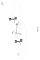
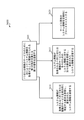
図1は、本開示の様々な態様による、ワイヤレス通信システム100の例を示す。ワイヤレス通信システム100は、1つまたは複数の基地局105、1つまたは複数のUE115、およびコアネットワーク130を含み得る。コアネットワーク130は、ユーザ認証、アクセス許可、追跡、インターネットプロトコル(IP)接続、および他のアクセス機能、ルーティング機能、またはモビリティ機能を提供し得る。基地局105は、バックホールリンク132(たとえば、S1など)を通じてコアネットワーク130とインターフェースし得る。基地局105は、UE115との通信のための無線構成およびスケジューリングを実行することができ、または基地局コントローラ(図示せず)の制御下で動作することができる。様々な例では、基地局105は、有線通信リンクまたはワイヤレス通信リンクであり得るバックホールリンク134(たとえば、X1など)を通じて、直接的にまたは(たとえば、コアネットワーク130を通じて)間接的にのいずれかで、互いに通信し得る。
FIG. 1 shows an example of a
基地局105は、1つまたは複数のアンテナを介して、UE115とワイヤレスに通信することができる。いくつかの例では、1つまたは複数のアンテナは、基地局サーバと併置された1つまたは複数の基地局アンテナ(および送受信機)および/または基地局サーバから離れて位置している1つまたは複数のRRHアンテナ(および送受信機)を含み得る。基地局105の各々は、それぞれの地理的カバレッジエリア110に通信カバレッジを提供することができる。いくつかの例では、基地局105は、トランシーバ基地局、無線基地局、アクセスポイント、無線送受信機、NodeB、eNodeB(eNB)、ホームNodeB(HNB)、ホームeNodeB、または何らかの他の適切な用語で呼ばれることがある。基地局105の地理的カバレッジエリア110は、カバレッジエリアの一部分のみを構成するセクタ(図示せず)に分割され得る。1つまたは複数の基地局105の地理的カバレッジエリア110は、ワイヤレス通信システム100のゾーンを定義し得る。ワイヤレス通信システム100は、異なるタイプの基地局105(たとえば、マクロセル基地局またはスモールセル基地局)を含み得る。異なる技術のための重複する地理的カバレッジエリア110があり得る。
いくつかの例では、ワイヤレス通信システム100は、LTEまたはLTE-Aネットワークであることがあり、またはそれらを含むことがある。ワイヤレス通信システム100は、5Gワイヤレス通信ネットワークなどの次世代ネットワークであることもあり、またはそれを含むこともある。LTE/LTE-Aネットワークおよび5Gネットワークでは、evolved node B(eNB)という用語は、一般に基地局105を表すために使用され得るが、UEという用語は、一般にUE115を表すために使用され得る。ワイヤレス通信システム100は、異なるタイプのeNBが様々な地理的領域にカバレッジを与える異種LTE/LTE-Aまたは5Gネットワークであり得る。たとえば、各eNBまたは基地局105は、マクロセル、スモールセル、または他のタイプのセルに通信カバレッジを提供し得る。「セル」という用語は、文脈に応じて、基地局、基地局と関連付けられるキャリアもしくはコンポーネントキャリア、またはキャリアもしくは基地局のカバレッジエリア(たとえば、セクタなど)を表すために使用され得る3GPP用語である。
In some examples, the
マクロセルは、一般に、比較的大きい地理的エリア(たとえば、半径数キロメートル)をカバーすることがあり、ネットワークプロバイダとのサービス契約を有するUE115による無制限のアクセスを許容し得る。スモールセルは、マクロセルと比較すると、マクロセルと同じまたはマクロセルとは異なる(たとえば、免許、免許不要などの)周波数帯域で動作し得る低電力基地局を含み得る。スモールセルは、様々な例に従って、ピコセル、フェムトセル、およびマイクロセルを含み得る。ピコセルは、たとえば、小さい地理的エリアをカバーすることができ、ネットワークプロバイダのサービスに加入しているUE115による無制限アクセスを許容し得る。フェムトセルも、小さい地理的エリア(たとえば、自宅)をカバーすることができ、フェムトセルとの関連性を有するUE115(たとえば、限定加入者グループ(CSG)中のUE115、自宅内のユーザのためのUE115など)による制限されたアクセスを提供し得る。マクロセルのためのeNBは、マクロeNBと呼ばれることがある。スモールセルのためのeNBは、スモールセルeNB、ピコeNB、フェムトeNB、またはホームeNBと呼ばれることがある。eNBは、1つまたは複数(たとえば、2つ、3つ、4つなど)のセルをサポートし得る。 Macrocells may generally cover a relatively large geographic area (eg, a few kilometers in radius) and may allow unlimited access by UE115 with a service contract with a network provider. A small cell may include a low power base station that, when compared to a macro cell, may operate in a frequency band that is the same as or different from the macro cell (eg, licensed, unlicensed, etc.). Small cells may include picocells, femtocells, and microcells, according to various examples. Picocell can, for example, cover a small geographic area and allow unlimited access by UE115 subscribing to the services of a network provider. The femtocell can also cover a small geographic area (eg, home) and is associated with the femtocell UE115 (eg, UE115 in a limited subscriber group (CSG)), for users in the home. May provide restricted access by (such as UE115). The eNB for the macro cell is sometimes referred to as the macro eNB. The eNB for the small cell is sometimes referred to as the small cell eNB, pico eNB, femto eNB, or home eNB. The eNB may support one or more cells (eg, two, three, four, etc.).
様々な開示される例のいくつかに適応し得る通信ネットワークは、階層化されたプロトコルスタックに従って動作するパケットベースネットワークであることがあり、ユーザプレーン中のデータはIPに基づくことがある。無線リンク制御(RLC)層は、論理チャネルを通じて通信するために、パケットのセグメント化とリアセンブルとを実行することができる。MAC層は、優先処理と、トランスポートチャネルへの論理チャネルの多重化とを実行することができる。MAC層はまた、MAC層において再送信を行ってリンク効率を改善するために、HARQを使用し得る。制御プレーンでは、無線リソース制御(RRC)プロトコル層は、UE115と基地局105との間のRRC接続の確立、構成、および維持を行うことができる。RRCプロトコル層はまた、ユーザプレーンデータのための無線ベアラのコアネットワーク130のサポートのためにも使用され得る。物理(PHY)層では、トランスポートチャネルは、物理チャネルにマッピングされ得る。
A communication network that can be adapted to some of the various disclosed examples may be a packet-based network that operates according to a layered protocol stack, and the data in the user plane may be IP-based. The wireless link control (RLC) layer can perform packet segmentation and reassembly to communicate through logical channels. The MAC layer can perform priority processing and multiplexing of logical channels to transport channels. The MAC layer can also use HARQ to perform retransmissions at the MAC layer to improve link efficiency. On the control plane, the Radio Resource Control (RRC) protocol layer can establish, configure, and maintain an RRC connection between
UE115は、ワイヤレス通信システム100全体に分散していることがあり、各UE115は固定式または移動式であり得る。UE115はまた、移動局、加入者局、モバイルユニット、加入者ユニット、ワイヤレスユニット、リモートユニット、モバイルデバイス、ワイヤレスデバイス、ワイヤレス通信デバイス、リモートデバイス、モバイル加入者局、アクセス端末、モバイル端末、ワイヤレス端末、リモート端末、ハンドセット、ユーザエージェント、モバイルクライアント、クライアント、もしくは何らかの他の好適な用語を含むことがあり、または当業者によってそのように呼ばれることがある。UE115は、携帯電話、スマートフォン、携帯情報端末(PDA)、ワイヤレスモデム、ワイヤレス通信デバイス、ハンドヘルドデバイス、タブレットコンピュータ、ラップトップコンピュータ、コードレス電話、ワイヤレスローカルループ(WLL)局、データカード、ユニバーサルシリアルバス(USB)ドングル、ワイヤレスルータなどであり得る。UE115は、マクロeNB、スモールセルeNB、中継基地局などを含む様々なタイプの基地局およびネットワーク機器と通信することが可能であり得る。UE115がワイヤレス通信システム100内を移動するにつれて、UE115はセルからセルへ、またはゾーンからゾーンへ(ゾーンは1つまたは複数のセルを含む)移動し得る。ワイヤレス通信システム100がUE中心のネットワークとして展開されるとき、UE115は、物理的なチャネルの再構成を伴わずにゾーン内をセルからセルへ移動することがあり、ネットワークは、UEのサービングセルの変化にもかかわらず、同じ無線リソースを介してデータ転送サービスを提供する。
The UE 115s may be distributed throughout the
ワイヤレス通信システム100において示されるワイヤレス通信リンク125は、UE115から基地局105へのアップリンク(UL)送信、または基地局105からUE115へのダウンリンク(DL)送信を搬送し得る。ダウンリンク送信は順方向リンク送信と呼ばれることもあり、一方、アップリンク送信は逆方向リンク送信と呼ばれることもある。ワイヤレス通信リンク125の各々は、1つまたは複数のキャリアを含むことがあり、各キャリアは、上で説明された様々な無線技術に従って変調される複数のサブキャリア(たとえば、異なる周波数の波形信号)から構成される信号であり得る。各々の変調された信号は、異なるサブキャリア上で送信されることがあり、制御情報(たとえば、基準信号、制御チャネルなど)、オーバーヘッド情報、ユーザデータなどを搬送することがある。ワイヤレス通信リンク125は、周波数分割複信(FDD)動作(たとえば、対のスペクトルリソースを使用する)またはTDD動作(たとえば、不対のスペクトルリソースを使用する)を使用して、双方向通信を送信することができる。FDD(たとえば、フレーム構造タイプ1)およびTDD(たとえば、フレーム構造タイプ2)に対するフレーム構造が定義され得る。
The
ワイヤレス通信システム100のいくつかの実施形態では、基地局105またはUE115は、アンテナダイバーシティ方式を利用して基地局105とUE115との間の通信品質および信頼性を改善するための複数のアンテナを含み得る。加えて、または代替的に、基地局105またはUE115は、同じまたは異なるコーディングされたデータを搬送する複数の空間層を送信するためにマルチパス環境を利用し得る、多入力多出力(MIMO)技法(たとえば、マッシブMIMO(たとえば、マルチアンテナMIMOおよびマルチユーザMIMO)技法ではない任意のMIMO、またはマッシブMIMO技法)を利用し得る。
In some embodiments of the
ワイヤレス通信システム100は、キャリアアグリゲーション(CA)またはマルチキャリア動作と呼ばれ得る特徴である、複数のセルまたはキャリア上の動作をサポートし得る。キャリアは、コンポーネントキャリア(CC)、層、チャネルなどと呼ばれることもある。「キャリア」、「コンポーネントキャリア」、「セル」、および「チャネル」という用語は、本明細書で互換的に使用され得る。UE115は、キャリアアグリゲーションのための複数のダウンリンクCCおよび1つまたは複数のアップリンクCCとともに構成され得る。キャリアアグリゲーションは、FDDコンポーネントキャリアとTDDコンポーネントキャリアの両方とともに使用され得る。
The
ワイヤレス通信システム100のいくつかの実施形態では、ワイヤレス通信システム100は、UE中心のネットワークを有し得る。ネットワーク側で、基地局105が定期的な同期(sync)信号をブロードキャストし得る。UE115は、同期信号を受信し、同期信号からネットワークのタイミングを取得し、ネットワークのタイミングを取得したことに応答して、パイロット信号を送信し得る。UE115によって送信されるパイロット信号は、ネットワーク内の複数のセル(たとえば、基地局105)によって同時に受信可能であり得る。複数のセルの各々はパイロット信号の強度を測定することができ、ネットワーク(たとえば、各々が1つまたは複数の中心に位置する送受信機および/もしくはRRHを介してUE115と通信している基地局105の1つまたは複数、ならびに/または、コアネットワーク130内の中心ノード)がUE115のためのサービングセルを決定することができる。UE115がパイロット信号を送信し続けるにつれて、ネットワークは、UE115に知らせて、または知らせることなく、UE115をあるサービングセルから別のサービングセルにハンドオーバーすることがある。システム情報(SI)は、ブロードキャストモードでUE115に送信されることがあり(たとえば、このとき基地局105は、基地局105のカバレッジエリア110内の任意のUE115によってSIが要求されているかどうか、または必要とされているかどうかにかかわらずSIを送信する)、または、オンデマンドモードで送信されることがある(たとえば、このとき基地局105は、1つまたは複数のUE115からSIに対する要求を受信したことに応答してSIを送信し、この要求は、UE115のパイロット信号に含まれることがあり、またはパイロット信号であることがある)。SIをオンデマンドモードで送信するとき、基地局105は、SIのブロードキャストを行わずに済ますことができ、このことは電力を節約し得る。
In some embodiments of the
図2は、本開示の様々な態様による、ワイヤレス通信システム200内のUEのモビリティの例を示す。より具体的には、図2は、それぞれの第1の基地局105-aおよび第2の基地局105-bのカバレッジエリア110-aおよび110-b内の様々な地点(たとえば、地点A、地点B、および地点C)へとUE115-aが動くときのUE115-aを示す。いくつかの例では、UE115-aは、図1に関して説明されたUE115の1つまたは複数の態様の例であることがあり、第1の基地局105-aおよび第2の基地局105-bは、図1に関して説明された基地局105の1つまたは複数の態様の例であることがある。
FIG. 2 shows examples of UE mobility within a
例として、UE115-aは、第1の基地局105-aのカバレッジエリア110-a内で電源が入れられることがあり、第1の基地局105-aのカバレッジエリア110-a内でSIの最初の取得を実行することがある。いくつかの例では、UE115-aは、第1の基地局105-aから定期的な同期信号のインスタンスを受信し、同期信号から、第1の基地局105-aによるSIのブロードキャストをいつどこで聴取すべきかを決定し、そして、第1の基地局105-aによってブロードキャストされるSIを聴取して受信することによって、SIの最初の取得を実行し得る。他の例では、UE115-aは、第1の基地局105-aから定期的な同期信号のインスタンスを受信し、同期信号から、第1の基地局105-aによるSIのブロードキャストをいつどこで聴取すべきかを、およびいくつかの場合には、SIに対する要求をいつどこで送信すべきかを決定し、SIに対する要求を送信し、そして、第1の基地局105-aによるSIのブロードキャストを聴取して受信することによって、SIの最初の取得を実行し得る。さらに他の例では、UE115-aは、サービス固有のSIが、ブロードキャストを介した受信と要求を介した受信のいずれかに利用可能であることを、第1の基地局105-aから受信された定期的な同期信号から決定し、そして、サービス固有のSIの聴取とサービス固有のSIの要求のいずれかを行うことによって、サービス固有のSIの初期の取得を実行し得る。 As an example, UE115-a may be powered up within coverage area 110-a of first base station 105-a and SI within coverage area 110-a of first base station 105-a. May perform the first acquisition. In some examples, the UE 115-a receives an instance of the periodic sync signal from the first base station 105-a, and from the sync signal, when and where the SI broadcast by the first base station 105-a. The first acquisition of SI can be performed by deciding what to listen to and then listening to and receiving the SI broadcast by the first base station 105-a. In another example, the UE 115-a receives an instance of the periodic sync signal from the first base station 105-a and listens to the SI broadcast from the first base station 105-a when and where. Decide when and, in some cases, when and where to send the request to the SI, send the request to the SI, and listen to the SI broadcast by the first base station 105-a. By receiving, the first acquisition of SI can be performed. In yet another example, the UE 115-a receives from the first base station 105-a that the service-specific SI is available for either receive via broadcast or receive via request. An initial acquisition of a service-specific SI can be performed by determining from the periodic synchronization signals and by either listening to the service-specific SI or requesting a service-specific SI.
まだ地点Aにある間は、UE115-aは、動的なSIの期限切れに基づいて、またはSIを最後に取得してから経過した時間に基づいて、SIを再取得すると決定し得る。UE115-aはまた、地点Aにおいて、SIが変化したことを示す同期信号のインスタンスを受信した後で、SIを再取得し得る。他の実施形態では、UE115-aは地点AにおいてSIを再取得しないことがある。 While still at point A, UE115-a may decide to reacquire the SI based on the dynamic SI expiration or the time elapsed since the last acquisition of the SI. UE115-a may also reacquire the SI at point A after receiving an instance of the sync signal indicating that the SI has changed. In other embodiments, UE115-a may not reacquire SI at point A.
地点Aから地点Bに移動すると、UE115-aはSIを再取得すると決定し得る。UE115-aは、たとえば、その動きに基づいて、地点Aと地点Bの間の距離に基づいて、動的なSIの期限切れに基づいて、またはSIを最後に取得してから経過した時間に基づいて、SIを再取得すると決定し得る。UE115-aはまた、地点Bにおいて、SIが変化したことを示す同期信号のインスタンスを受信した後で、SIを再取得し得る。他の実施形態では、UE115-aは地点BにおいてSIを再取得しないことがある。 Moving from point A to point B, UE115-a may decide to reacquire SI. UE115-a, for example, based on its movement, based on the distance between points A and B, based on the dynamic SI expiration, or based on the time elapsed since the last SI acquisition. It can be decided to reacquire SI. UE115-a may also reacquire the SI at point B after receiving an instance of the sync signal indicating that the SI has changed. In other embodiments, UE115-a may not reacquire SI at point B.
地点Bから地点Cへ、および第2の基地局105-bのカバレッジエリア110-bの中へ移動すると、UE115-aは、第2の基地局105-bからのSIの最初の取得を実行し得る。他の実施形態では、UE115-aは、地点BにおいてSIを再取得する理由の1つが発生しない限り、第2の基地局105-bからSIを取得する必要はない。いくつかの場合、SIはカバレッジエリア110-bにおいて取得されないことがあり、それは、第1のカバレッジエリア110-aおよび第2のカバレッジエリア110-bが共通のゾーンのメンバーとして動作するように構成され、その結果、UE115-aのためのデータ転送サービスがネットワークによって提供されるからである。 Moving from point B to point C and into the coverage area 110-b of the second base station 105-b, UE115-a performs the first acquisition of SI from the second base station 105-b. Can be. In other embodiments, UE 115-a does not need to acquire SI from the second base station 105-b unless one of the reasons for reacquiring SI at point B occurs. In some cases, SI may not be acquired in coverage area 110-b, which configures the first coverage area 110-a and the second coverage area 110-b to act as members of a common zone. As a result, the data transfer service for UE115-a is provided by the network.
図2は、様々なUEのモビリティ状態の間に、および様々な理由でSIが取得され得ることを示す。たとえば、UEが(たとえば、SIの最初の取得の一部として)ネットワークに接続されないとき、SIは取得されることがある。SIはまた、UEがネットワークに接続した後で、かつUEが静止している間に、(たとえば、タイマーもしくはSIが期限切れになったので、またはSIが変化したことを(たとえば、同期信号のインスタンスにおいて、またはページングメッセージにおいて)ネットワークが示したので)取得されることがある。SIはまた、UEがネットワークに接続した後で、かつUEが移動している間に、(たとえば、UEが静止している間にSIが再取得される理由のいずれかにより、UEが新しい位置に移動したので、SIが取得された以前の位置からUEがある距離を移動したので、または新しい基地局もしくはセルのカバレッジエリアにUEが移動したので)取得されることがある。 Figure 2 shows that SI can be acquired during different UE mobility states and for different reasons. For example, an SI may be acquired when the UE is not connected to the network (for example, as part of the initial acquisition of the SI). The SI also indicates that the UE has connected to the network and while the UE is stationary (for example, because the timer or SI has expired, or the SI has changed (for example, an instance of the sync signal). May be retrieved (as indicated by the network) or in a paging message. The SI is also in a new position after the UE is connected to the network and while the UE is moving (for example, because the SI is reacquired while the UE is stationary). May be acquired (because the UE has moved some distance from the previous position where the SI was acquired, or because the UE has moved to a new base station or cell coverage area).
図3Aおよび図3Bは、本開示の様々な態様による、それぞれの第1の基地局、第2の基地局、第3の基地局、第4の基地局、第5の基地局、および第6の基地局の例示的な送信/受信のタイムライン305、320、335、350、365、および380を示す。基地局の送信は、最初のSIの取得(たとえば、システムの選択または新しいセルもしくはゾーンへの移動の間のSIの取得)の間に、またはSI変更の取得(たとえば、SIの変化に際した、または動的なSIの期限切れに際した)の間に、1つまたは複数のUEによって受信され、UEによって使用され得る。いくつかの例では、基地局は、図1または図2に関して説明されたワイヤレス通信システム100または200の異なるセルまたはゾーンなどの、ワイヤレス通信システムのそれぞれの異なるセルまたはゾーンに属し得る。いくつかの例では、第1の基地局、第2の基地局、第3の基地局、第4の基地局、第5の基地局、および第6の基地局は、図1に関して説明された基地局105の1つまたは複数の態様の例であり得る。
3A and 3B show the first base station, the second base station, the third base station, the fourth base station, the fifth base station, and the sixth base station, respectively, according to various aspects of the present disclosure. Shown are exemplary transmission /
図3Aおよび図3Bに示されるように、基地局の各々は、定期的な同期信号(Sync)310、325、340、355、370、または385を送信し得る。図3Aの例では、基地局の各々はまた、定期的な、オンデマンドのマスターシステム情報ブロック(MSIB)315、330、342、または358を送信する。いくつかの場合、同期信号のインスタンスおよびMSIBのインスタンスは一緒に、LTE/LTE-Aマスター情報ブロック(MIB)、システム情報ブロック1(SIB1)、およびSIB2に含まれる情報と等価な情報を提供し得る。図3Bの例では、基地局の各々は、サービス固有のSIB375、390を送信する。 As shown in FIGS. 3A and 3B, each of the base stations may transmit periodic sync signals (Sync) 310, 325, 340, 355, 370, or 385. In the example of Figure 3A, each of the base stations also transmits periodic, on-demand master system information blocks (MSIB) 315, 330, 342, or 358. In some cases, the sync signal instance and the MSIB instance together provide information equivalent to the information contained in LTE / LTE-A Master Information Block (MIB), System Information Block 1 (SIB1), and SIB2. obtain. In the example of Figure 3B, each of the base stations transmits service-specific SIB375,390.
いくつかの実施形態では、基地局によって送信される同期信号は、アクセスネットワーク内の複数のセル(たとえば、ゾーン内の複数のセル)に共通である(たとえば、セル固有ではない)ことがあり、単一周波数ネットワーク(SFN)の方式で複数のセルの中のセルの各々から(たとえば、セルの中の複数の基地局の各々から)ブロードキャストされることがある。同期信号はセル識別子を含む必要はない。いくつかの実施形態では、同期信号は、比較的短い持続時間を有することがあり、または比較的低い頻度で送信されることがある。たとえば、同期信号は、1シンボルの持続時間を有し、10秒に1回送信されることがある。他の例では、同期信号は、無線フレームごとに1回など、より頻繁に送信されることがある。いくつかの実施形態では、同期信号のインスタンスは、数ビットの情報を搬送し得る。より具体的には、いくつかの実施形態では、同期信号のインスタンスは、後で送信されるMSIBを要求するかどうかを決定するためにUEが使用し得る情報、後で送信されるMSIBをいつどこで要求すべきかを決定するためにUEが使用し得る情報(たとえば、MSIB送信要求を送信するための頻度およびタイミングの情報)、後で送信されるMSIBがいつどこで受信され得るかを決定するためにUEが使用し得る情報(たとえば、チャネル、頻度、および/またはタイミングの情報)、MSIBがいつ変化したかを示す情報、または、同期信号を送信するセルもしくはゾーンを1つまたは複数の他のセルもしくはゾーン(たとえば、近隣のセルもしくはゾーン)と区別するためにUEが使用し得る情報などの、情報を含み得る。いくつかの実施形態では、同期信号のインスタンスは、後で送信されるサービス固有のSIBを要求するかどうかを決定するためにUEが使用し得る情報、後で送信されるサービス固有のSIBをいつどこで要求するかをUEが決定するために使用し得る情報(たとえば、サービス固有のSIB送信要求を送信するための頻度およびタイミングの情報)、または、後で送信されるサービス固有のSIBがいつどこで受信され得るかを決定するためにUEが使用し得る情報(たとえば、チャネル、頻度、および/またはタイミングの情報)を含み得る。 In some embodiments, the synchronization signal transmitted by the base station may be common (eg, not cell-specific) to multiple cells in the access network (eg, cells in the zone). It may be broadcast from each of the cells in a plurality of cells (for example, from each of a plurality of base stations in a cell) in a single frequency network (SFN) manner. The sync signal does not have to include the cell identifier. In some embodiments, the sync signal may have a relatively short duration or may be transmitted relatively infrequently. For example, a sync signal has a duration of one symbol and may be transmitted once every 10 seconds. In another example, the sync signal may be transmitted more often, such as once per radio frame. In some embodiments, an instance of the sync signal can carry several bits of information. More specifically, in some embodiments, an instance of the sync signal will use information that the UE can use to determine whether to request an MSIB to be transmitted later, when the MSIB to be transmitted later. Information that the UE can use to determine where to request (for example, frequency and timing information for sending MSIB send requests), to determine when and where MSIBs sent later can be received. Information that the UE can use (for example, channel, frequency, and / or timing information), information that indicates when the MSIB has changed, or one or more other cells or zones that send synchronization signals. It can contain information, such as information that the UE can use to distinguish it from cells or zones (eg, neighboring cells or zones). In some embodiments, an instance of the sync signal uses information that the UE can use to determine whether to request a service-specific SIB that will be sent later, when the service-specific SIB that will be sent later. Information that the UE can use to determine where to request (for example, frequency and timing information for sending a service-specific SIB send request), or when and where a service-specific SIB sent later It may contain information that the UE may use to determine if it can be received (eg, channel, frequency, and / or timing information).
いくつかの実施形態では、同期信号は、MSIBもしくはサービス固有のSIBの送信要求がその上で送信されるべきPHY層チャネルを示すことがあり、または、いくつかの条件のもとでのMSIBもしくはサービス固有のSIBの送信要求の送信のための特別なPHY層チャネルを示すことがある。いくつかの場合、同期信号はまた、MSIBもしくはサービス固有のSIBの送信要求をどのように送信するか(たとえば、MSIBまたはサービス固有のSIBの送信要求を送信するときに使用されるべきフォーマット)、または、いくつかの条件のもとでMSIBもしくはサービス固有のSIBの送信要求をどのように送信するかを示し得る。他の実施形態では、同期信号は、MSIBまたはサービス固有のSIBの送信要求の送信のために、より少数のパラメータを規定し得る。しかしながら、これは、基地局がより多くの条件のもとで(または常に)MSIBまたはサービス固有のSIBの送信要求を聴取することを必要とすることがあり、これはUEリレーのエネルギー効率に影響することがある。 In some embodiments, the sync signal may indicate the PHY layer channel on which the MSIB or service-specific SIB transmit request should be transmitted, or the MSIB or under some conditions. It may indicate a special PHY layer channel for sending service-specific SIB send requests. In some cases, the sync signal also sends an MSIB or service-specific SIB send request (for example, the format that should be used when sending an MSIB or service-specific SIB send request). Alternatively, it may indicate how to send an MSIB or service-specific SIB send request under some conditions. In other embodiments, the sync signal may specify fewer parameters for the transmission of MSIB or service-specific SIB transmission requests. However, this may require the base station to (or always) listen to MSIB or service-specific SIB transmission requests under more conditions, which affects the energy efficiency of UE relays. I have something to do.
UEは、同期信号のインスタンスを受信し、同期信号に基づいてアクセスネットワークのタイミングを取得することができる。アクセスネットワークのタイミングを取得したことに応答して、UEはパイロット信号を送信することができる。パイロット信号は、アクセスネットワーク内の複数のセルによって(たとえば、アクセスネットワークのゾーン内の複数のセルによって)同時に受信可能であり得る。いくつかの実施形態では、パイロット信号は、空間シグネチャ(たとえば、サウンディング参照信号(SRS:sounding reference signal))を含み得る。いくつかの実施形態では、パイロット信号は、同期信号のインスタンスによって示されるMSIB送信要求機会において送信され得る。いくつかの実施形態では、パイロット信号は、所定のランダムシーケンスまたはUEによって生成されるランダムシーケンスを用いて送信されることがあり、このランダムシーケンスは、最初の取得手順の間にUEを一時的に特定するためにアクセスネットワーク(たとえば、ネットワークの基地局)によって使用され得る。いくつかの実施形態では、パイロット信号は、MSIBの送信要求であることがあり、またはそれを含むことがある。 The UE can receive an instance of the sync signal and get the timing of the access network based on the sync signal. In response to acquiring the timing of the access network, the UE can send a pilot signal. The pilot signal can be received simultaneously by multiple cells in the access network (eg, by multiple cells in the zone of the access network). In some embodiments, the pilot signal may include a spatial signature (eg, a sounding reference signal (SRS)). In some embodiments, the pilot signal may be transmitted at the MSIB transmission request opportunity indicated by an instance of the synchronization signal. In some embodiments, the pilot signal may be transmitted using a predetermined random sequence or a random sequence generated by the UE, which random sequence temporarily populates the UE during the initial acquisition procedure. It can be used by an access network (eg, a network base station) to identify it. In some embodiments, the pilot signal may be, or may include, a transmission request of the MSIB.
MSIB315、330、342、または358は、UEがアクセスネットワークとの接続をいつどこで確立できるかを示し得る。MSIBは、アクセスネットワーク、セル、もしくはゾーンを特定する情報、UEがアクセスネットワークを使用することを許可される(または使用すべきである)かどうかを示す情報、または、UEがアクセスネットワークをどのように使用できるかを示す情報(たとえば、UEの電源が入るときに、またはUEが停止中(OoS:out-of-service)もしくは無線リンク障害(RLF:radio link failure)のイベントを検出した後で新しいセルもしくはゾーンに移動するときに、UEがアクセスネットワークをどのように使用できるかを示す情報)などの、情報を含み得る。アクセスネットワーク、セル、またはゾーンを特定する情報は、公衆交換電話網(PLMN)識別子(ID)、トラッキングエリアコード(TAC)、セル識別子(セルID)、またはゾーン識別子(ゾーンID)を含み得る。UEがアクセスネットワークを使用することを許可される(または使用すべきである)かどうかを示す情報は、セルまたはゾーンのための、システム選択情報またはアクセス制約情報(たとえば、無線品質情報、混雑回避情報、または限定加入者グループ(CSG)情報)を含み得る。UEがアクセスネットワークをどのように使用できるかを示す情報は、アクセス構成情報(たとえば、ランダムアクセスチャネル(RACH)情報、またはUEタイマーおよび定数情報)を含み得る。MSIBはまた、物理ランダムアクセスチャネル(PRACH)情報、物理ダウンリンク共有チャネル(PDSCH)情報、物理ダウンリンク制御チャネル(PDCCH)情報、物理アップリンク共有チャネル(PUSCH)情報、物理アップリンク制御チャネル(PUCCH)情報、およびSRS情報などのPHY層構成情報、または、ワイヤレス通信システムのPHY層にアクセスするために使用可能な他の情報を含み得る。 MSIB315, 330, 342, or 358 may indicate when and where the UE can establish a connection with the access network. The MSIB may identify information that identifies the access network, cell, or zone, indicates whether the UE is allowed (or should use) to use the access network, or how the UE uses the access network. Information that can be used for (for example, when the UE is powered on, or after detecting an out-of-service (OoS) or radio link failure (RLF) event. It can contain information, such as information about how the UE can use the access network when navigating to a new cell or zone. Information that identifies an access network, cell, or zone can include a public switched telephone network (PLMN) identifier (ID), tracking area code (TAC), cell identifier (cell ID), or zone identifier (zone ID). The information that indicates whether the UE is allowed (or should use) to use the access network is system selection or access constraint information (eg, radio quality information, congestion avoidance) for the cell or zone. Information, or Limited Subscriber Group (CSG) information) may be included. Information indicating how the UE can use the access network can include access configuration information (eg, random access channel (RACH) information, or UE timer and constant information). MSIB also includes physical random access channel (PRACH) information, physical downlink shared channel (PDSCH) information, physical downlink control channel (PDCCH) information, physical uplink shared channel (PUSCH) information, and physical uplink control channel (PUCCH). ) Information, and PHY layer configuration information such as SRS information, or other information that can be used to access the PHY layer of a wireless communication system.
サービス固有のSIB375、390は、UEが特定のサービスのためにアクセスネットワークとの接続をいつどこで確立できるかを示し得る。特定のサービスは、たとえば、エネルギー効率の良いサービス、信頼性の高いサービス、レイテンシの少ないサービス、ブロードキャストサービス、または小データサービスを含み得る。これらのサービスは、UEがネットワークにアクセスすることを可能にするために、追加のSI(たとえば、MSIBに含まれないSI)を必要とし得る。たとえば、LTEにおけるマルチメディアブロードキャストマルチキャストサービス(MBMS)は、MBMSにアクセスすることに関連する追加の構成情報をSIB13の中に有し得る。加えて、無線アクセス技術が進化するにつれて、特定のサービスのための追加のSIの送信を可能にするだけではなく、異なるサービスの性能を改善するために同じサービス固有のSIの異なる構成の送信も可能にすることが望ましいことがある。追加のサービス固有のSIは、たとえば、アクセスネットワークおよびセルを特定することについての情報(たとえば、PLMN ID、TAC、またはセルID)を含み得る。追加のサービス固有のSIはまた、セルのための情報およびおアクセス制約(無線品質、混雑回避、CSGを含む)を含み得る。追加のサービス固有のSIはさらに、アクセス構成についての情報(RACH、UEタイマーおよび制約、ならびに他の5Gネットワークの等価物)を含み得る。 Service-specific SIB375,390 may indicate when and where a UE can establish a connection with an access network for a particular service. Certain services may include, for example, energy efficient services, reliable services, low latency services, broadcast services, or small data services. These services may require additional SIs (eg, SIs not included in the MSIB) to allow the UE to access the network. For example, the Multimedia Broadcast Multicast Service (MBMS) in LTE may have additional configuration information in SIB13 related to accessing the MBMS. In addition, as wireless access technology evolves, it not only allows the transmission of additional SIs for specific services, but also the transmission of different configurations of SIs specific to the same service to improve the performance of different services. It may be desirable to enable it. Additional service-specific SIs may include, for example, information about identifying access networks and cells (eg, PLMN ID, TAC, or cell ID). Additional service-specific SIs may also include information and access constraints for the cell, including radio quality, congestion avoidance, and CSG. Additional service-specific SIs may also contain information about access configurations (RACHs, UE timers and constraints, and other 5G network equivalents).
たとえば、サービス固有のSIBは、ワイドエリアネットワーク(WAN) internet of everything(IOE)におけるSIに対して、より効率的なアクセス構成およびより長い有効タイマーを可能にするための情報を含むことがあり、WAN IOEにおいては、IOEデバイスは長いスリープ期間の後までネットワークと接続しないことがあるので、低電力動作が望ましいことがある。加えて、WAN IOEなどのサービスは、IOEデバイスが追加のSIを読み取る必要をなくすために、MSIBに異なる情報を含めることがある。 For example, a service-specific SIB may contain information to enable more efficient access configurations and longer valid timers for SIs in the wide area network (WAN) internet of everything (IOE). In WAN IOE, low power operation may be desirable as IOE devices may not connect to the network until after a long sleep period. In addition, services such as WAN IOE may include different information in the MSIB to eliminate the need for the IOE device to read additional SI.
ここで(図3Aの)第1の基地局の送信/受信タイムライン305を見ると、第1の基地局は、以前に説明されたように定期的な同期信号310を送信し得る。同期信号のインスタンスを受信すると、最初の取得を実行することが必要なUEは、第1の基地局と関連付けられるアクセスネットワーク(かついくつかの場合には、第1の基地局、そのセル、またはそのゾーンを、他の基地局、セル、またはゾーンと区別するための情報)を特定し、UEがアクセスネットワークのSIを取得できる(または取得すべきである)かどうかを決定し、UEがアクセスネットワークのSIをどのように取得できるかを決定し得る。UEがアクセスネットワークのSIをどのように取得できるかを決定するとき、UEは、同期信号と関連付けられるシグナリングを介して、第1の基地局が固定された定期的なシグナリングを用いてブロードキャスト(またはブロードビーム)送信モードにおいてMSIB315を送信することを決定し得る。UEはまた、同期信号から、MSIB送信を受信するための時間を特定し得る。最初の取得を実行する必要のないUEは、同期信号から、UEが新しいセルまたは新しいゾーンに移動したかどうかを決定し得る。UEが新しいセルまたは新しいゾーンに移動したとUEが決定するとき、UEは、新しいセルまたは新しいゾーンから新しいまたは更新されたSIを取得するために、同期信号に含まれる情報を使用し得る。
Looking at the transmit / receive
(図3Aの)第2の基地局の送信/受信タイムライン320を参照すると、第2の基地局は、以前に説明されたように定期的な同期信号325を送信し得る。同期信号のインスタンスを受信すると、最初の取得を実行することが必要なUEは、第2の基地局と関連付けられるアクセスネットワーク(かついくつかの場合には、第2の基地局、そのセル、またはそのゾーンを、他の基地局、セル、またはゾーンと区別するための情報)を特定し、UEがアクセスネットワークのSIを取得できる(または取得すべきである)かどうかを決定し、UEがアクセスネットワークのSIをどのように取得できるかを決定し得る。UEがアクセスネットワークのSIをどのように取得できるかを決定するとき、UEは、同期信号と関連付けられるシグナリングを介して、定期的なシグナリングを伴うオンデマンドブロードキャスト(またはブロードビーム)送信モードで第2の基地局がMSIB330を送信すること(すなわち、第2の基地局が、UEからMSIB送信要求信号332を受信すると、定期的なスケジューリングで、MSIBのブロードキャスト(またはブロードビーム)送信を開始すること)を決定し得る。UEはまた、同期信号から、MSIB送信要求をいつどこで送信するか、およびMSIB送信を受信するための時間を特定し得る。最初の取得を実行する必要のないUEは、同期信号から、UEが新しいセルまたは新しいゾーンに移動したかどうかを決定し得る。UEが新しいセルまたは新しいゾーンに移動したとUEが決定するとき、UEは、新しいセルまたは新しいゾーンから新しいまたは更新されたSIを取得するために、同期信号に含まれる情報を使用し得る。
With reference to the transmit / receive
(図3Aの)第3の基地局の送信/受信タイムライン335を参照すると、第3の基地局は、以前に説明されたように定期的な同期信号340を送信し得る。同期信号のインスタンスを受信すると、最初の取得を実行することが必要なUEは、第3の基地局と関連付けられるアクセスネットワーク(かついくつかの場合には、第3の基地局、そのセル、またはそのゾーンを、他の基地局、セル、またはゾーンと区別するための情報)を特定し、UEがアクセスネットワークのSIを取得できる(または取得すべきである)かどうかを決定し、UEがアクセスネットワークのSIをどのように取得できるかを決定し得る。UEがアクセスネットワークのSIをどのように取得できるかを決定するとき、UEは、同期信号と関連付けられるシグナリングを介して、不定期のシグナリングを伴うオンデマンドブロードキャスト(またはブロードビーム)送信モードで第3の基地局がMSIB342を送信すること(すなわち、第3の基地局がUEからMSIB送信要求信号345を受信するとMSIBのブロードキャスト(またはブロードビーム)送信をスケジューリングすること、およびMSIBがいつ送信されるかを決定するためにUEがスケジューリング情報(Sched.)348についてスケジューリングチャネル(たとえば、PDCCH)を監視し得ること)を決定し得る。UEはまた、同期信号から、MSIB送信要求をいつどこで送信するかを特定し得る。最初の取得を実行する必要のないUEは、同期信号から、UEが新しいセルまたは新しいゾーンに移動したかどうかを決定し得る。UEが新しいセルまたは新しいゾーンに移動したとUEが決定するとき、UEは、新しいセルまたは新しいゾーンから新しいまたは更新されたSIを取得するために、同期信号に含まれる情報を使用し得る。
With reference to the transmit / receive
(図3Aの)第4の基地局の送信/受信タイムライン350を参照すると、第4の基地局は、以前に説明されたように定期的な同期信号355を送信し得る。同期信号のインスタンスを受信すると、最初の取得を実行することが必要なUEは、第4の基地局と関連付けられるアクセスネットワーク(かついくつかの場合には、第4の基地局、そのセル、またはそのゾーンを、他の基地局、セル、またはゾーンと区別するための情報)を特定し、UEがアクセスネットワークのSIを取得できる(または取得すべきである)かどうかを決定し、UEがアクセスネットワークのSIをどのように取得できるかを決定し得る。UEがアクセスネットワークのSIをどのように取得できるかを決定するとき、UEは、同期信号と関連付けられるシグナリングを介して、ユニキャスト(またはナロービーム)送信モードで第4の基地局がMSIB358を送信すること(すなわち、第4の基地局がUEからMSIB送信要求信号360を受信するとMSIBのユニキャスト(またはナロービーム)送信をスケジューリングすること、およびMSIBがいつ送信されるかを決定するためにUEがスケジューリング情報(Sched.)362についてスケジューリングチャネル(たとえば、PDCCH)を監視し得ること)を決定し得る。UEはまた、同期信号から、MSIB送信要求をいつどこで送信するかを特定し得る。最初の取得を実行する必要のないUEは、同期信号から、UEが新しいセルまたは新しいゾーンに移動したかどうかを決定し得る。UEが新しいセルまたは新しいゾーンに移動したとUEが決定するとき、UEは、新しいセルまたは新しいゾーンから新しいまたは更新されたSIを取得するために、同期信号に含まれる情報を使用し得る。
With reference to the transmit / receive
図3Aに示される送信/受信タイムライン305、320、335、および350の各々において、基地局はMSIB315、330、342、または358を送信する。UEは、いくつかの例では、共通の物理制御チャネル(たとえば、PDCCH)上でシステム情報無線ネットワーク一時識別子(SI-RNTI)を監視し、SI-RNTIと関連付けられるダウンリンク割当てメッセージを復号し、ダウンリンク割当てメッセージに含まれる情報に従って共有チャネル(たとえば、PDSCH)上でMSIBを受信することによって、MSIBを受信し得る。代替的に、無線ネットワーク一時識別子(RNTI;たとえば、セルRNTI(C-RNTI)またはゾーンRNTI(Z-RNTI))がUEのために割り当てられるとき、UEは、共通の物理制御チャネル(たとえば、PDCCH)上でRNTIを監視し、RNTIと関連付けられるダウンリンク割当てメッセージを復号し、ダウンリンク割当てメッセージに含まれる情報に従って共有チャネル(たとえば、PDSCH)上でMSIBを受信し得る。別の代替形態では、UEはブロードキャストSIを受信するためにSI-RNTIを監視し得るが、UEはユニキャストSIを受信するためにUEに専用に割り振られたRNTI(たとえば、C-RNTIまたはゾーンRNTI)も使用し得る。
At each of the transmit / receive
セルにキャンプオンしているとき、UEは、MSIBに含まれる情報が変化したかどうかを決定するために、セルによって送信される定期的な同期信号の各インスタンスの少なくとも一部分を復号し得る。代替的に、UEは、定期的な同期信号のN個ごとのインスタンスの少なくとも一部分を復号することができ、または、1つまたは複数の事象が発生すると定期的な同期信号のインスタンスの少なくとも一部分を復号することができる。同期信号の後続のインスタンスの復号された部分は、セルのSIが変化したかどうかを示すために設定され得る情報(たとえば、修正フラグまたは値タグ)を含み得る。(たとえば、送信/受信タイムライン305において同期信号310のインスタンス310-aを受信した後で)セルのSIが変化したと決定すると、UEは、変化したSIを伴うMSIB(たとえば、MSIB315-a)を要求および/または受信し得る。
When camping on a cell, the UE may decode at least a portion of each instance of the periodic sync signal sent by the cell to determine if the information contained in the MSIB has changed. Alternatively, the UE can decode at least a portion of every N instances of a periodic sync signal, or at least a portion of an instance of a periodic sync signal when one or more events occur. It can be decrypted. The decrypted portion of a subsequent instance of the sync signal may contain information (eg, a modification flag or value tag) that can be set to indicate whether the SI of the cell has changed. If the UE determines that the SI of a cell has changed (for example, after receiving instance 310-a of
UEがワイヤレス通信システムのカバレッジエリア内を移動するにつれて、UEは、図1もしくは図2に関して説明された異なるセル(またはカバレッジエリア110、110-a、110-b、またはゾーン)の同期信号、または図3Aに関して説明された異なるセル(もしくは基地局もしくはゾーン)などの、異なるセル(またはゾーン)の同期信号を検出し得る。セルまたはゾーンの同期信号を検出すると、UEは、UEが新しい同期信号(たとえば、異なるセル、基地局、またはゾーンの同期信号)を検出したかどうかを決定するために、UEが最後にSIを取得したセル(または基地局またはゾーン)に対応するセルグローバル識別情報(CGI)(または基地局識別情報コード(BSIC:base station identity code)またはゾーン識別情報)を、同期信号と関連付けられるCGI(またはBSICまたはゾーン識別情報)と比較し得る。
As the UE moves within the coverage area of the wireless communication system, the UE may have a sync signal in a different cell (or
MSIBのオンデマンド送信は、UEによって(たとえば、初期アクセスの間に)、またはアクセスネットワークによって(たとえば、MSIBに含まれる情報が変化するとき、または専用のSIBが送信されるとき)、開始され得る。いくつかの場合、送信/受信タイムライン305、320、335、または350の1つに従って信号を送受信する基地局は、送信/受信モードを切り替え、これによって、送信/受信タイムラインの一方から送信/受信タイムラインの他方に切り替えることができる。この切替えは、たとえば、ネットワークの負荷または混雑の状況に基づいて行われ得る。いくつかの実施形態では、基地局は、さらに、または代替的に、MSIB送信について「オンデマンドユニキャスト(またはナロービーム)」モードと「常時オンブロードキャスト(またはブロードビーム)」モードを切り替えることができる。いくつかの例では、基地局は、それが動作している1つまたは複数のモードを、定期的な同期信号においてシグナリングし得る。
On-demand transmission of MSIB can be initiated by the UE (for example, during initial access) or by the access network (for example, when the information contained in the MSIB changes or when a dedicated SIB is transmitted). .. In some cases, a base station that sends and receives a signal according to one of the transmit / receive
ここで(図3Bの)第5の基地局の送信/受信タイムライン365を見ると、第5の基地局は、サービス固有の定期的な同期信号370を送信し得る。サービス固有の定期的な同期信号370は、サービス固有のSIが利用可能であるという指示を含み得ることを除き、同期信号310、325、340、355の1つの例であり得る。サービス固有の定期的な同期信号370はまた、どのサービスのサービス固有のSIが利用可能であるかについての情報を含み得る。加えて、サービス固有の定期的な同期信号370は、異なるサービスに対するサービス固有のSIがいつ要求または送信され得るかのスケジュールに関する情報を含み得る。例として、あるサービス固有のSIは、あらゆる同期信号期間において送信されるとは限らない。同期されたMBMSサービスは、サービス固有のSIBが、たとえば数秒のオーダーで送信されることを要求するだけであることがあるので、あらゆる同期信号期間の間に利用可能であるとは限らない。同期信号のインスタンスを受信すると、UEは、UEが利用可能なサービス固有のSIの1つまたは複数を必要としていると決定し得る。サービス固有の定期的な同期信号370に従って、UEはSIB送信(Tx)要求372を送信し得る。UEは、ある特定のサービス(たとえば、サービス1)に関するSIの送信に対するSIB Tx要求372-aを送信することができ、続いて、異なる特定のサービス(たとえば、サービス2)に関するSIの送信に対するSIB Tx要求372-bを送信することができる。SIB Tx要求372の受信に応答して、1つまたは複数の基地局は、サービス固有のSIB375をUEに送信し得る。第5の基地局は、SIB Tx要求372-aに応答してサービス固有のSIB375-aを送信することができ、SIB Tx要求372-bに応答してサービス固有のSIB375-bも送信することができる。代替的に、第5の基地局は、SIB Tx要求372を待機することなく、サービス固有のSIB375をブロードキャストすることができる。この代替形態では、サービス固有の定期的な同期信号370は、UEがサービス固有のSIB375を受信するためにいつどのリソースを聴取し得るかを示し得る。
Looking at the transmit / receive
(図3Bの)第6の基地局の送信/受信タイムライン380を参照すると、第6の基地局は、サービス固有の定期的な同期信号385を送信し得る。サービス固有の定期的な同期信号385は、サービス固有のSIが利用可能であるという指示を含み得ることを除き、同期信号310、325、340、355の1つの例であり得る。しかしながら、サービス固有の定期的な同期信号385は、SIが利用可能である実際のサービスを示さないことがある。代わりに、送信/受信タイムライン380において、UEは、それに対するSIが望まれるサービスを、SIB Tx要求388において明示的に特定することが必要とされる。サービス固有の同期信号385は、UEがSIB Tx要求388をいつどのリソースで送信し得るかに関する情報を含み得る。したがって、同期信号のインスタンスを受信すると、UEは、UEが利用可能なサービス固有のSIの1つまたは複数を必要としていると決定し得る。サービス固有の定期的な同期信号385に従って、UEは、要求されるSIを特定するSIB Tx要求388を送信し得る。SIB Tx要求388の受信に応答して、第6の基地局は、サービス固有のSIB390をUEに送信し得る。サービス固有のSIB390は、一緒に、または共同で、単一の送信において送信されることがあり、または別々に送信されることがある。
With reference to the transmit / receive
サービス固有の定期的な同期信号370、385と、SIB Tx要求372、388とのいずれかにおいて示されるサービスに基づいて、基地局は、サービス固有のSIB375、390をUEに送信し得る。サービス固有のSIB375、390は、サービスを改善し、またはサービス要件を満たすように特別に構成されるSIパラメータなどの、サービス固有の構成を含み得る。たとえば、サービス固有の構成は、IOEデバイスが節電モード(PSM)またはディープスリープから起動した後で、SIを再取得するようにIOEデバイスに要求する、有効タイマーまたはSI読取り要件を含み得る。たとえば、IOEデバイスは、特定の値タグを有するSIを取得することがあり、次いで、(たとえば、デバイスがIOEデバイスであることの結果として)拡大された期間の間、PSMに移行することができる。IOEデバイスが起動する時間までに、SIは2回以上変化している可能性がある。実際には、SIがSI値タグに対して使用可能な値の数に等しい回数変化する可能性すらあり、これは、IOEデバイスによって取得されるSIが、IOEデバイスが起動したときにIOEデバイスによって検出されるSIと同じ値タグを偶然にも有することがあるということを意味する。IOEデバイスが更新されたSIを取得すべきかどうかを決定するために、IOEデバイスがSI値タグに依拠する場合、IOEデバイスは、新しいSIが取得されるべきではないと決定し得る。しかしながら、有効タイマーまたはSI読取り要件は、IOEデバイスが更新されたSIを取得することを、SI値タグがそれ以外のことを示す場合であっても確実にするために使用され得る。たとえば、有効タイマーまたはSI読取り要件は、規定された時間の満了の後でIOEデバイスがSIを再取得することを要求することがあり、その時間は、一例では、IOEデバイスのPSM時間に等しいことがある。代替的に、有効タイマーは、サービス固有のSIB375、390のサービス固有の構成の一部として受信され得る。この場合、有効タイマーは、各SI値タグのラップアラウンドの間に少なくとも一度SIを再取得することをIOEデバイスに要求する、時間の長さに設定され得る。したがって、事業者がSIを10分ごとに変更し、SI値タグの範囲が0〜31である場合、有効タイマーは320分に設定され得る。有効タイマーは他の要因に基づくこともある。有効タイマーまたはSI読取り要件は、サービス固有のSIB375、390においてサービス固有の構成の一部としてIOEデバイスに搬送され得る。
Based on the service indicated in either the service-specific periodic sync signals 370, 385 and the SIB Tx requests 372, 388, the base station may transmit the service-
ある例として、いくつかのLTE規格では、UEは、SIが有効であると確認された瞬間から3時間後に、記憶されているSIを無効であるものとして見なすことがある。いくつかの例外がLTEにおいて当てはまることがあるが(たとえばcsg-PhysCellIdRange、しかしこの例外は、UEがCSGセルにキャンプオンしていない場合には更新されたSIが利用可能ではないことがあるという事実によるものである)、3時間という要件は、PSMに入ることがあるIOEデバイス、またはSI値タグが異なる周波数で循環するIOEデバイスを含む、多くのデバイスに対して適切ではないことがある。したがって、WAN IOEデバイスに対しては、有効タイマーが、WAN IOEネットワークに関するSIに対して延長または短縮されることがある。 As an example, in some LTE standards, the UE may consider a stored SI to be invalid three hours after the moment the SI is confirmed to be valid. Some exceptions may apply in LTE (eg csg-PhysCellIdRange, but this exception is the fact that the updated SI may not be available if the UE is not camping on the CSG cell. The requirement of 3 hours may not be appropriate for many devices, including IOE devices that may enter PSM, or IOE devices whose SI value tags circulate at different frequencies. Therefore, for WAN IOE devices, the valid timer may be extended or shortened for SI for WAN IOE networks.
サービス固有のSIB375、390はまた、MBMSのために定義されるパラメータのようなサービス固有のパラメータなどの、サービス固有の情報を含み得る。WAN IOEデバイスでは、サービス固有の構成は、IOEデバイスが任意の必要なSIを付加的に受信するために複数の要求を送信する必要がないように、単一のSIBに含まれることがある。 Service-specific SIB375,390 may also contain service-specific information, such as service-specific parameters such as parameters defined for MBMS. For WAN IOE devices, service-specific configurations may be included in a single SIB so that the IOE device does not have to send multiple requests to additionally receive any required SI.
加えて、複数のサービスに対応する複数のサービス固有のSIがサポートされるとき、ネットワークは、各サービスのためのSIの送信をサポートするために異なる送信モードを使用し得る。したがって、たとえば、WAN IOE SIは定期的にブロードキャストされることがあるが、ノミナルのSIはオンデマンドで送信されることがある。 In addition, when multiple service-specific SIs for multiple services are supported, the network may use different transmission modes to support the transmission of SIs for each service. So, for example, WAN IOE SI may be broadcast on a regular basis, while nominal SI may be transmitted on demand.
オンデマンドのシナリオでは、UEがSIB Tx要求372、388において2つ以上のサービスのためのSIを要求する場合、対応する基地局は、各サービスに対して別々のSIを提供するか、すべての望まれるサービスに対して共通のSIを提供するかのいずれかであることがあり、たとえば、共通のSIを提供する場合、基地局は、各々の要求されるサービスに対するサービス要件に基づいて、パラメータに対して最も厳しい構成値を適用し得る。 In an on-demand scenario, if the UE requests SI for more than one service in SIB Tx requests 372, 388, the corresponding base station either provides a separate SI for each service or all. It may be either providing a common SI for the desired service, for example, when providing a common SI, the base station has parameters based on the service requirements for each required service. The strictest configuration values can be applied to.
定期的な、またはオンデマンドのMSIBに加えて、基地局は、1つまたは複数の定期的なSIBまたはオンデマンドの他のSIB(OSIB)を送信し得る。OSIBは、SIB1またはSIB2以外のLTE/LTE-A SIBの1つまたは複数に含まれる情報と等価な情報(たとえば、事業者が無線アクセス技術(RAT)内かRAT間かのシステム選択を管理することを可能にするための情報、UEが1つまたは複数のサービスの可用性および構成を発見するための情報)を含み得る。OSIBの1つの例示的な送信が図4に示される。 In addition to regular or on-demand MSIBs, base stations may transmit one or more regular SIBs or other on-demand SIBs (OSIBs). OSIB manages information equivalent to information contained in one or more LTE / LTE-A SIBs other than SIB1 or SIB2 (for example, the operator manages the system selection within Radio Access Technology (RAT) or between RATs. It may contain information to enable it, information for the UE to discover the availability and configuration of one or more services). One exemplary transmission of OSIB is shown in Figure 4.
図4は、本開示の様々な態様による、同期信号、MSIB、およびOSIBの、基地局105-cによる送信を示すスイムレーン図400である。図4はまた、UE115-bがアクセスネットワークのSIの最初の取得を実行することによる、MSIBおよびOSIBの要求および受信を示す。いくつかの例では、基地局は、図1または図2に関して説明された基地局の1つまたは複数の態様を組み込み得る。同様に、UE115-bは、図1または図2に関して説明されたUE115の1つまたは複数の態様を組み込み得る。
FIG. 4 is a swimlane diagram 400 showing transmission of synchronization signals, MSIB, and OSIB by base station 105-c according to various aspects of the present disclosure. Figure 4 also shows the request and reception of MSIB and OSIB by UE115-b performing the first acquisition of SI in the access network. In some examples, the base station may incorporate one or more aspects of the base station described with respect to FIG. 1 or FIG. Similarly, UE 115-b may incorporate one or more aspects of
405において、基地局105-cは、図3Aに関して説明されたように、定期的な同期信号のインスタンスを送信し得る。UE115-bは、同期信号のインスタンスを受信し、ブロック410において、同期信号のインスタンスを処理して、UE115-bがMSIB送信要求を送信することが必要であると決定し、415において、基地局105-cからMSIBを取得することができる。UE115-bはまた、同期信号のインスタンスから、MSIB送信要求をいつどこで送信すべきかということと、基地局105-cによるMSIBの送信をいつどこで予期すべきかということとを、決定することができる。
At 405, base station 105-c may transmit instances of periodic sync signals as described with respect to FIG. 3A. UE115-b receives an instance of the sync signal, processes the instance of the sync signal in
420において、基地局105-cはMSIBを送信し得る。UE115-bは、MSIBを受信し、ブロック425において、MSIBに含まれる情報を処理することができる。UE115-bはまた、任意選択で、OSIB送信要求を準備することができる。いくつかの例では、任意のOSIB送信要求は、基地局105-cが動作しているセルもしくはゾーンからUE115-bがSIを事前に取得していないとき、または、セルもしくはゾーンに対するキャッシュされたSIが期限切れになっているとき、または、セルもしくはゾーンのためのSIが変化したと(たとえば、同期信号から、SIの変化をシグナリングするMSIBの中の情報から、またはページングメッセージから)UEが決定するとき、または、新しいSIが提供され得る位置(たとえば、新しい近隣セルリスト等価情報が提供され得る位置、または新しい全地球測位システム(GPS)支援情報が提供され得る位置)にUEがあるとUEが(たとえば、RRC_IDLEの間に)決定するとき、(たとえば、ブロック425において)準備され、(たとえば、430において)送信され得る。いくつかの場合、OSIB送信要求は、どのOSIB情報が要求されているかを示し得る。たとえば、UE115-bは、OSIB送信要求において、どのSI(たとえば、どのタイプのSIまたはどのSIB)をUEが受信することを望むかを示し得る。いくつかの例では、単一のOSIB送信要求430が送信されることがあり、単一のOSIB送信要求430は、UEが受信することを望む他のSIの1つまたは複数の要素を示し得る(たとえば、UEが受信することを望む他のSIの各要素に対しては、バイナリ値が真に設定され得る)。他の例では、UE115-bは、異なるOSIB送信要求においていくつかのタイプの他のSIを要求することがあり、UEは、複数のOSIB送信要求を基地局に送信することがある。
At 420, base station 105-c may transmit MSIB. UE115-b can receive the MSIB and process the information contained in the MSIB in
基地局105-cは、OSIB送信要求(または複数のOSIB送信要求)を受信し、ブロック435において、440または445におけるUEへの送信のために、1つまたは複数のOSIBを準備することができる。いくつかの実施形態では、基地局は、OSIB送信要求においてUEによって要求されるSIを含む、1つまたは複数のOSIBを準備し得る。加えて、または代替的に、基地局105-c(および/または基地局が通信する別のネットワークノード)は、どのSIがOSIBにおいてUE115-bに送信されるべきかを決定し得る。基地局105-cおよび/または他のネットワークノードは、たとえば、UE識別情報、UEタイプ、基地局がUEのために取得した能力情報、またはUEについて知られている(かつUEから取得される可能性のある)他の情報に基づいて、どのSIをUE115-bに送信すべきかを決定し得る。このようにして、UE115-bに送信されるSIの量を最適化することができ、これは、電力を節約すること、リソースを解放することなどの役に立つことがある。
Base station 105-c may receive an OSIB transmit request (or multiple OSIB transmit requests) and, in
前に示されたように、OSIBは、SIB1またはSIB2以外のLTE/LTE-A SIBの1つまたは複数に含まれる情報と等価な情報(たとえば、事業者がRAT内かRAT間かのシステム選択を管理することを可能にするための情報、UEが1つまたは複数のサービスの可用性および構成を発見するための情報)を含み得る。OSIBに含まれる情報は、基地局が、UE機能のサブセットに基づいて、UE能力に基づいて、またはUEサービス要件に基づいて、情報をUEに配信することを可能にするために、SIに基づいて番号付けられ編成され得る(たとえば、基地局は、UEがMBMSサービスを使用することが可能ではないとき、UEにMBMS情報を配信しないことがある)。いくつかの場合、OSIBに含まれる情報は、LTE/LTE-A SIBに含まれる情報と同じように、またはそれに類似して、番号を付けられ編成されることがある。 As previously indicated, the OSIB is information equivalent to the information contained in one or more LTE / LTE-A SIBs other than SIB1 or SIB2 (eg, system selection of whether the operator is within RAT or between RATs). Information to allow the UE to manage the availability and configuration of one or more services). The information contained in the OSIB is based on SI to allow base stations to deliver information to UEs based on a subset of UE capabilities, based on UE capabilities, or based on UE service requirements. Can be numbered and organized (for example, a base station may not deliver MBMS information to a UE when it is not available for MBMS services). In some cases, the information contained in the OSIB may be numbered and organized in the same manner as or similar to the information contained in the LTE / LTE-A SIB.
OSIBに含まれる情報は、UEによって効率的に受信または処理され得るように編成され得る。たとえば、情報は、UEが情報を可能な限り低い頻度で読むことができるように、編成され得る。いくつかの実施形態では、情報は、情報の範囲に基づいて、情報がシステム全体に適用されるか、コンステレーション内で適用されるか、セルごとに適用されるか、もしくはゾーンごとに適用されるかに基づいて、情報が有効なままである時間長(たとえば、有効時間)に基づいて、または情報が準静的であるか動的であるかに基づいて、編成され得る。情報が非常に動的に変化するとき、情報は、少ないレイテンシで送信され得るように編成され得る。 The information contained in the OSIB can be organized so that it can be efficiently received or processed by the UE. For example, the information can be organized so that the UE can read the information as infrequently as possible. In some embodiments, the information is applied system-wide, within a constellation, cell-by-cell, or zone-by-zone, based on the scope of the information. It can be organized based on how long the information remains valid (eg, valid time), or whether the information is quasi-static or dynamic. When information changes very dynamically, it can be organized so that it can be transmitted with low latency.
OSIBのオンデマンド送信は、UEによって(たとえば、初期アクセスの間に)、またはアクセスネットワークによって(たとえば、OSIBに含まれる情報が変化するとき、または専用のSIBが送信されるとき)、開始され得る。 OSIB on-demand transmissions can be initiated by the UE (for example, during initial access) or by the access network (for example, when the information contained in the OSIB changes or when a dedicated SIB is transmitted). ..
前に説明されたように、基地局は、いくつかの場合、MSIB送信について「オンデマンドユニキャスト(またはナロービーム)」モードと「常時オンブロードキャスト(またはブロードビーム)」モードと「オンデマンドブロードキャスト(またはブロードビーム)」モードとを切り替えることができる。基地局はまた、OSIB送信について「オンデマンドユニキャスト(またはナロービーム)」モードと「常時オンブロードキャスト(またはブロードビーム)」モードと「オンデマンドブロードキャスト(またはブロードビーム)」モードとを切り替えることができる。「常時オンブロードキャスト(またはブロードビーム)」OSIB送信では、OSIB送信スケジュールは、MSIB送信においてシグナリングされ得る。 As explained earlier, base stations often use "on-demand unicast (or narrow beam)" mode, "always on-broadcast (or broad-beam)" mode, and "on-demand broadcast (or broad beam)" mode for MSIB transmission. Or you can switch between "broad beam)" mode. The base station can also switch between "on-demand unicast (or narrow beam)" mode, "always on-broadcast (or broad-beam)" mode, and "on-demand broadcast (or broad-beam)" mode for OSIB transmission. .. For "always on-broadcast (or broadcast)" OSIB transmissions, the OSIB transmission schedule can be signaled in the MSIB transmission.
いくつかの場合、UEは、UEの位置の変化に基づいて、MSIBまたはOSIBを受信して処理することができる。いくつかの場合、MSIBまたはOSIBは、それぞれのMSIB送信要求またはOSIB送信要求を送信した後で、受信され処理され得る。この点について、図5は、第1のゾーン505、第2のゾーン510、第3のゾーン515、および第4のゾーン520のそれぞれのカバレッジエリアのベン図500を示す。いくつかの実施形態では、本開示の様々な態様によれば、第1のゾーン505は5Gワイヤレス通信ネットワークを含むことがあり、第2のゾーン510は第1の近隣RAT(たとえば、近隣RAT1)を含むことがあり、第3のゾーン515は第2の近隣RAT(たとえば、近隣RAT2)を含むことがあり、第4のゾーン520は第3の近隣RAT(たとえば、近隣RAT3)を含むことがある。例として、5Gワイヤレス通信ネットワークは、図1または図2に関して説明されたワイヤレス通信システム100または200の態様を組み込み得る。第1の近隣RAT、第2の近隣RAT、および第3の近隣RATの各々はまた、ワイヤレス通信システム100または200の態様を組み込み得る。5Gワイヤレス通信ネットワーク、第1の近隣RAT、第2の近隣RAT、および第3の近隣RATは、異なる形態をとることもある。
In some cases, the UE can receive and process the MSIB or OSIB based on changes in the position of the UE. In some cases, the MSIB or OSIB may be received and processed after sending each MSIB send request or OSIB send request. In this regard, FIG. 5 shows a Venn diagram 500 of the respective coverage areas of the
UEが第1のゾーン505において5Gワイヤレス通信ネットワークへのアクセスを最初に取得するとき、または、UEが5Gワイヤレス通信ネットワーク内を移動するにつれて、UEは、第1の近隣RAT、第2の近隣RAT、または第3の近隣RATのためのSIを取得し得る。いくつかの場合、UEは、距離に基づくSIの取得を使用して、近隣RATのためのSIを取得し得る。UEは、UEの現在の位置と、UEが最後に近隣RAT SIを取得したときのUEの位置との間の距離を決定する(たとえば、計算する)ことによって、距離に基づくSIの取得を利用し得る。決定された距離が閾値の距離を超えるとき、UEは、SI取得手順を開始することができる(たとえば、UEは近隣RAT SIを含むOSIBを受信することができ、またはUEはその中でUEが近隣RAT SIを要求するOSIB送信要求を送信することができる)。閾値の距離は、ネットワークによって構成されることがあり、MSIBにおいて(たとえば、MSIBにおいて示される測定構成の一部として)示されることがある。
When the UE first gains access to the 5G wireless communication network in
いくつかの実施形態では、距離に基づくSIの取得は、近隣RATごとに利用され得る。他の実施形態では、距離に基づくSIの取得は、集団的な近隣RATごとに利用され得る。 In some embodiments, distance-based acquisition of SI can be utilized on a per-neighboring RAT basis. In other embodiments, distance-based acquisition of SI can be utilized per collective neighborhood RAT.
いくつかの場合、UEは、定期的な同期信号においてシグナリングされるSIの変化に基づいて、MSIBまたはOSIBを受信して処理することができる。いくつかの場合、MSIBまたはOSIBは、それぞれのMSIB送信要求またはOSIB送信要求を送信した後で、受信され処理され得る。 In some cases, the UE can receive and process the MSIB or OSIB based on changes in the SI signaled in the periodic sync signal. In some cases, the MSIB or OSIB may be received and processed after sending each MSIB send request or OSIB send request.
図6は、本開示の様々な態様による、同期信号、MSIB、およびOSIBの、基地局105-dによる送信を示すスイムレーン図600である。図6はまた、UE115-cがシステム情報更新を実行することによる、MSIBおよびOSIBの要求および受信を示す。いくつかの例では、基地局105-dは、図1、図2、または図4に関して説明された基地局105の1つまたは複数の態様を組み込み得る。同様に、UE115-cは、図1、図2、または図4に関して説明されたUE115の1つまたは複数の態様を組み込み得る。
FIG. 6 is a swimlane diagram 600 showing transmission of sync signals, MSIB, and OSIB by base station 105-d according to various aspects of the present disclosure. Figure 6 also shows the MSIB and OSIB requests and receipts as UE115-c performs a system information update. In some examples, base station 105-d may incorporate one or more aspects of
605において、基地局105-dは、図3Aに関して説明されたような定期的な同期信号のインスタンス、またはページングメッセージを送信し得る。同期信号またはページングメッセージのインスタンスは、基地局を含むセルのためのSIが変化したことを示す情報(たとえば、修正フラグまたは値タグ)を含み得る。 At 605, base station 105-d may transmit a periodic sync signal instance, or paging message, as described with respect to FIG. 3A. An instance of a sync signal or paging message may contain information (eg, a correction flag or value tag) indicating that the SI for the cell containing the base station has changed.
いくつかの実施形態では、同期信号またはページングメッセージのインスタンスは、SIが変化したという汎用インジケータ(たとえば、修正フラグ)を含み得る。汎用インジケータまたは修正フラグは、たとえば、SIが変化したときにインクリメントされるカウンタ値、または、MSIBに含まれるSIが変化したとき(またはUEがMSIBを再取得することをネットワークが予期するとき)に真(たとえば、論理「1」)に設定され、もしくはMSIBに含まれるSIが変化していないとき(またはUEがMSIBを再取得することをネットワークが予期しないとき)に偽(たとえば、論理「0」)に設定される、ブール変数(たとえば、バイナリ値)を含み得る。同期信号またはページングメッセージのインスタンスは、さらに、または代替的に、SIのいくつかの要素が変化したかどうかを示し得る。たとえば、同期信号またはページングメッセージのインスタンスは、Public Warning System(PWS;たとえば、Earthquake and Tsunami Warning System(ETWS)またはCommercial Mobile Alert System(CMAS))などのサービスのためのSIが変化したかどうかを示すことがあり、これは、復号を簡単にし、そのような情報がより頻繁に変化するときにバッテリ持続時間を改善し得る。 In some embodiments, the instance of the sync signal or paging message may include a generic indicator (eg, a correction flag) that the SI has changed. A generic indicator or modifier flag is, for example, a counter value that is incremented when the SI changes, or when the SI contained in the MSIB changes (or when the network expects the UE to reacquire the MSIB). False (for example, logic "0") when set to true (for example, logic "1") or when the SI contained in the MSIB has not changed (or when the network does not expect the UE to reacquire the MSIB) ”) Can contain Boolean variables (eg, binary values). An instance of a sync signal or paging message can further or alternatively indicate whether some elements of SI have changed. For example, an instance of a sync signal or paging message indicates whether the SI for services such as the Public Warning System (PWS; for example, Earthquake and Tsunami Warning System (ETWS) or Commercial Mobile Alert System (CMAS)) has changed. This can simplify decryption and improve battery life when such information changes more frequently.
UE115-cは、同期信号またはページングメッセージのインスタンスを受信し、ブロック610において、同期信号またはページングメッセージのインスタンスを処理し(たとえば、同期信号またはページングメッセージと関連付けられるカウンタ値を以前に受信されたカウンタ値と比較し、または、修正フラグが真に設定されるか偽に設定されるかを決定し)、基地局を含むセルまたはゾーンのためのSIが変化したと決定し、(いくつかの場合)変化したSIがUEに関連すると決定することができる。UEはまた、UEがMSIB送信要求を送信する必要があると決定して、615において、基地局から変化したSIを含むMSIBを取得することができる。UEはまた、同期信号またはページングメッセージのインスタンスから、MSIB送信要求をいつどこで送信すべきか、および基地局によるMSIBの送信をいつどこで予期すべきかを決定することができる。 UE115-c receives an instance of a sync signal or paging message and, in block 610, processes the instance of the sync signal or paging message (for example, a counter previously received with a counter value associated with the sync signal or paging message). Compare with the value or determine if the correction flag is set to true or false) and determine that the SI for the cell or zone containing the base station has changed (in some cases). ) It can be determined that the changed SI is related to the UE. The UE can also determine at 615 that the UE needs to send an MSIB transmit request and obtain an MSIB containing the altered SI from the base station. The UE can also determine when and where to send an MSIB send request from an instance of a sync signal or paging message, and when and where to expect an MSIB to be sent by a base station.
620において、基地局105-dはMSIBを送信し得る。いくつかの場合、MSIBは、他のSIが変化したかどうかを示す情報を含み得る。たとえば、MSIBは、他のSIが変化したという汎用インジケータ(たとえば、修正フラグ)を含み得る。汎用インジケータまたは修正フラグは、たとえば、OSIBに含まれるSIが変化したときにインクリメントされるカウンタ値、または、OSIBに含まれるSIが変化したとき(またはUEがOSIBを再取得することをネットワークが予期するとき)に真(たとえば、論理「1」)に設定され、もしくはOSIBに含まれるSIが変化していないとき(またはUEがOSIBを再取得することをネットワークが予期しないとき)に偽(たとえば、論理「0」)に設定される、ブール変数(たとえば、バイナリ値)を含み得る。MSIBはさらに、または代替的に、他のSIのいくつかの要素が変化したかどうかを示し得る。たとえば、MSIBは、SIのタイプごとに、または等価的なLTE/LTE-A SIB(たとえば、MBMSサービスのためのSIが変化したかどうかを示すために真または偽に設定される第1のブール変数、PWSサービス(たとえば、CMASサービスまたはETWSサービス)のためのSIが変化したかどうかに基づいて真または偽に設定される第2のブール変数など)ごとに、値タグを含み得る。 At 620, base station 105-d may transmit MSIB. In some cases, the MSIB may contain information indicating whether other SIs have changed. For example, the MSIB may include a generic indicator (eg, a correction flag) that another SI has changed. The generic indicator or modification flag is, for example, a counter value that is incremented when the SI contained in the OSIB changes, or the network expects the UE to reacquire the OSIB when the SI contained in the OSIB changes. False (for example) when set to true (for example, logical "1") or when the SI contained in the OSIB has not changed (or when the network does not expect the UE to reacquire the OSIB) , Can contain Boolean variables (eg, binary values) that are set to the logic "0"). MSIB may, or alternativeally, indicate whether some elements of other SI have changed. For example, the MSIB is a first Boolean that is set to true or false for each type of SI or for the equivalent LTE / LTE-A SIB (for example, whether the SI for the MBMS service has changed). Each variable may contain a value tag, such as a second Boolean variable that is set to true or false based on whether the SI for the PWS service (eg CMAS service or ETWS service) has changed.
UE115-cは、MSIBを受信し、ブロック625において、MSIBに含まれる情報を処理することができる。UEは、UEに対して有用な他のSI(たとえば、UEによって監視されるSI)が変化したので要求される必要があるかどうかを決定するために、どのSIが変化したかを示す情報を使用し得る。たとえば、UEは、MSIBに含まれるOSIBカウンタ値を以前に受信されたOSIBカウンタ値と比較し、または、OSIB修正フラグが真に設定されるか偽に設定されるかを決定し、または、他のSIの1つまたは複数の監視される要素に対する値タグを他のSIの1つまたは複数の監視される要素に対する以前に受信された値タグと比較して、OSIBが要求される必要があるかどうかを決定し得る。UEに対して有用な他のSIが変化していないとき、UEはOSIB送信要求を送信する必要はない。しかしながら、UEに対して有用な他のSIが変化していないとき、UEは、(たとえばブロック625において)OSIB送信要求を準備して、(たとえば630において)送信することができる。いくつかの場合、OSIB送信要求は、汎用的な要求(たとえば、基地局にすべての他のSIを返させる要求、または、基地局がUEに対して有用であると見なしたあらゆるSIを基地局が返すことを許可する要求)であり得る。他の場合、OSIB送信要求は、どのOSIB情報が要求されているかを示し得る。たとえば、UEは、OSIB送信要求において、どのSI(たとえば、どのタイプのSIまたはどのSIB)をUEが受信することを望むかを示し得る。
UE115-c can receive the MSIB and process the information contained in the MSIB in
基地局105-dは、OSIB送信要求を受信し、ブロック635において、640または645におけるUEへの送信のために、1つまたは複数のOSIBを準備することができる。いくつかの実施形態では、基地局は、OSIB送信要求においてUEによって要求されるSIを含む、OSIBを準備し得る。加えて、または代替的に、基地局(および/または基地局が通信する別のネットワークノード)は、どのSIがOSIBにおいてUEに送信されるべきかを決定し得る。基地局および/または他のネットワークノードは、たとえば、UE識別情報、UEタイプ、基地局がUEのために取得した能力情報、またはUEについて知られている(かつUEから取得される可能性のある)他の情報に基づいて、どのSIをUEに送信すべきかを決定し得る。このようにして、UEに送信されるSIの量を最適化することができ、これは、電力を節約すること、リソースを解放することなどの役に立つことがある。
Base station 105-d may receive an OSIB transmit request and, in
以下の表は、5Gワイヤレス通信システムにおけるMSIBおよびOSIBへのSIの例示的な割振りを与える。 The table below gives an exemplary allocation of SI to MSIB and OSIB in 5G wireless communication systems.

図4〜図6の各々は、かつ本開示の残りはある程度、MSIBまたはOSIBの送信に主に焦点を当てるが、任意の数のMSIBまたはOSIBが、単一のMSIB送信要求および/もしくはOSIB送信要求に応答して、または複数のMSIB送信要求および/もしくはOSIB送信要求に応答して、個々に、または集団で送信され得る。いくつかの場合、マスターシステム情報は、MSIB、MTC_SIB、またはマスター情報を搬送する他のSIBの1つまたは複数の間で分散されることがある。いくつかの場合、他のシステム情報は、近隣セル/ゾーン情報を搬送するOSIB1、MBMS関連情報を搬送するOSIB2、PWS関連情報を搬送するOSIB3、または他の情報を搬送する他のSIBの1つまたは複数の間で分散されることがある。MSIBまたはOSIBは、1つまたは複数の要素も含み得る。SIが変化するとき、修正フラグまたは値タグは、たとえば、MSIBごとに、MSIB内の要素ごとに、OSIBごとに、またはOSIB内の要素ごとに、送信または受信され得る。 Each of FIGS. 4-6, and to some extent the rest of the disclosure, focuses primarily on the transmission of MSIB or OSIB, but any number of MSIB or OSIB may have a single MSIB transmission request and / or OSIB transmission. It can be sent individually or collectively in response to a request or in response to multiple MSIB and / or OSIB send requests. In some cases, master system information may be distributed among one or more of the MSIB, MTC_SIB, or other SIB that carries the master information. In some cases, the other system information is one of OSIB1, which carries neighboring cell / zone information, OSIB2, which carries MBMS-related information, OSIB3, which carries PWS-related information, or another SIB that carries other information. Or it may be distributed among multiple. MSIB or OSIB may also include one or more elements. When the SI changes, correction flags or value tags can be sent or received, for example, per MSIB, per element within the MSIB, per OSIB, or per element within the OSIB.
図7は、本開示の様々な態様による、ワイヤレス通信において使用するためのUE115-dのブロック図700を示す。UE115-dは、図1〜図6に関して説明されたUE115の1つまたは複数の態様の例であり得る。UE115-dはまた、プロセッサであってよく、またはそれを含むことがある。UE115-dは、UE受信機モジュール710、SI取得モジュール720、またはUE送信機モジュール730を含み得る。SI取得モジュール720は、SI取得モードモジュール735、UE SI要求モジュール740、またはSI受信モジュール745を含み得る。これらのモジュールの各々は、互いに通信していることがある。
FIG. 7 shows a block diagram 700 of the UE 115-d for use in wireless communication according to various aspects of the present disclosure. UE115-d may be an example of one or more aspects of UE115 described with respect to FIGS. 1-6. UE115-d may also be or include a processor. The UE 115-d may include a
UE115-dのモジュールは、個別にまたは集合的に、ハードウェア中の適用可能な機能の一部またはすべてを実行するように適合された1つまたは複数の特定用途向け集積回路(ASIC)を使用して実装され得る。代替的に、機能は、1つまたは複数の集積回路上で、1つまたは複数の他の処理ユニット(またはコア)によって実行され得る。他の例では、当技術分野で知られている任意の方式でプログラムされ得る他のタイプの集積回路(たとえば、ストラクチャード/プラットフォームASIC、フィールドプログラマブルゲートアレイ(FPGA)、システムオンチップ(SoC)、または他のセミカスタムIC)が使用され得る。各モジュールの機能はまた、1つまたは複数の汎用または特定用途向けプロセッサによって実行されるようにフォーマットされた、メモリにおいて具現化された命令を用いて、全体的または部分的に実装され得る。 UE115-d modules use one or more application-specific integrated circuits (ASICs) individually or collectively adapted to perform some or all of the applicable functions in the hardware. Can be implemented. Alternatively, the function may be performed by one or more other processing units (or cores) on one or more integrated circuits. In other examples, other types of integrated circuits that can be programmed in any manner known in the art (eg, structured / platform ASICs, field programmable gate arrays (FPGAs), system-on-chip (SoCs), or Other semi-custom ICs) may be used. The functionality of each module can also be implemented in whole or in part using memory-embodied instructions formatted to be executed by one or more general purpose or application-specific processors.
いくつかの例では、UE受信機モジュール710は、少なくとも1つの高周波(RF)受信機を含み得る。UE受信機モジュール710またはRF受信機は、図1に関して説明されたワイヤレス通信システム100の1つまたは複数の通信リンクなどの、ワイヤレス通信システムの1つまたは複数の通信リンクを通じて、様々なタイプのデータまたは制御信号(すなわち、送信)を受信するために使用され得る。例として、UE受信機モジュール710は、図3A、図3B、および図4に関して説明されたように、定期的な同期信号を受信するために使用され得る。UE受信機モジュール710はまた、図3A、図3B、および図4を参照してやはり説明されたように、1つまたは複数の形式のSIを含む様々な信号を受信するために使用され得る。以下でより詳細に説明されるように、同期信号およびSI信号(たとえば、図3Aの定期的な同期信号310、325、340、または355、および図3AのブロードキャストMSIB315、330、342、またはユニキャストMSIB358)の受信および処理は加えて、SI取得モジュール720を通じて支援され得る。
In some examples, the
いくつかの例では、UE送信機モジュール730は、少なくとも1つのRF送信機を含み得る。UE送信機モジュール730またはRF送信機は、図1に関して説明されたワイヤレス通信システム100の1つまたは複数の通信リンクなどの、ワイヤレス通信システムの1つまたは複数の通信リンクを通じて、様々なタイプのデータまたは制御信号(すなわち、送信)を送信するために使用され得る。例として、図3Aに関して説明されたように、UE送信機モジュール730は、MSIB送信要求信号332、345、360を送信するために使用され得る。MSIB送信要求信号332、345、360の送信は加えて、たとえば、以下でより詳細に説明されるように、SI取得モジュール720を通じて支援され得る。
In some examples, the
SI取得モジュール720は、UE115-dのためのワイヤレス通信の1つまたは複数の態様を管理するために使用され得る。具体的には、UE115-dにおいて、SI取得モジュール720は、上で説明された実施形態のいくつかの態様に従って、基地局105からのSIの取得を支援するために使用され得る。SI取得モジュール720は、SI取得モードモジュール735、UE SI要求モジュール740、またはSI受信モジュール745を含み得る。
The
SI取得モードモジュール735は、たとえば、図3A、図3B、および図4に示されるように、定期的な同期信号310、325、340、355のUE115-dによる受信を支援するために、UE115-dによって使用され得る。受信された定期的な同期信号310、325、340、355は、UE115-dが、たとえばSIの送信を受信するために、MSIB送信要求信号332、345、360などの要求信号を送信すべきかどうかを、UE115-dに示し得る。たとえば、UE115-dは、UE115-dによって送信されるいずれの要求とも無関係に、SIが基地局105によってブロードキャストされ得ることをUE115-dに示す、定期的な同期信号310を受信し得る。この事例では、SI取得モードモジュール735は、UE115-dがSIを受信するために要求が必要ではないことを決定し得る。しかしながら、別の例では、UE115-dは、定期的な同期信号325、340、355を受信することがあり、これらの同期信号は各々、UE115-dがSIを受信するためにSIに対する要求を(たとえばMSIB送信要求信号332、345、360の形式で)送信すべきであることを示し得る。この事例では、SI取得モードモジュール735は、UE115-dがSIを受信するために要求が必要であると決定し得る。したがって、SI取得モードモジュール735は、UE115-dがブロードキャストSIモードを有するネットワークにおいて動作しているか、オンデマンドSIモードを有するネットワークにおいて動作しているかを決定するように構成され得る。
The SI
UE115-dがオンデマンドSIモードを使用してネットワークにおいて動作している場合、これはUE115-dがSIを受信するための要求を送信すべきであることを意味し、UE SI要求モジュール740が、そのような要求の作成を支援するために使用され得る。例として、UE SI要求モジュール740は、図3AのMSIB送信要求信号332、345、360のいずれか1つを組み立てるために使用され得る。UE SI要求モジュール740は、MSIB送信要求信号332、345、360をどのように組み立てるかを決定するために、定期的な同期信号325、340、355とともに含まれる情報を使用し得る。たとえば、定期的な同期信号325、340、355は、MSIB送信要求信号332、345、360がどこに送信されるべきか、ならびにそのような信号のタイミングを示す情報を含み得る。
If the UE115-d is operating in the network using on-demand SI mode, this means that the UE115-d should send a request to receive the SI, and the UE
SI受信モジュール745は、UE115-dに送信されるSIの受信を支援するために使用され得る。SIは、UE115-dによって送信される要求を必要とすることなく、ブロードキャストとして送信され得る。この例では、SI取得モードモジュール735は、SIがブロードキャストを介して受信されるべきであることをSI受信モジュール745に示し得る。SI受信モジュール745は次いで、SIのブロードキャストの所定のチャネルまたはタイミングなどの、定期的な同期信号310とともに含まれる情報を使用して、SIの受信を支援し得る。別の例では、SIは、UE115-dによって送信される要求に応答したブロードキャストまたはユニキャストのいずれかとして送信され得る。これらの例では、SI取得モードモジュール735は、要求に応答して、ブロードキャストとユニキャストのいずれかとしてSIが受信されるべきであることをSI受信モジュール745に示し得る。SI受信モジュール745は次いで、SIのブロードキャストまたはユニキャストの所定のチャネルまたはタイミングなどの、定期的な同期信号325、340、355とともに含まれる情報を使用して、SIの受信を支援し得る。
図8は、様々な例による、ワイヤレス通信において使用するためのUE115-eのブロック図800を示す。UE115-eは、図1〜図7に関して説明されるUE115の1つまたは複数の態様の例であり得る。UE115-eは、(図7の)UE115-dの対応するモジュールの例であり得る、UE受信機モジュール710-a、SI取得モジュール720-a、および/またはUE送信機モジュール730-aを含み得る。UE115-eはまた、プロセッサ(図示せず)を含み得る。これらの構成要素の各々は、互いに通信していることがある。SI取得モジュール720-aは、SI取得モードモジュール735-a、UE SI要求モジュール740-a、および/またはSI受信モジュール745-aを含み得る。SI取得モードモジュール735-aはさらに、同期信号受信モジュール805および/またはSI取得モード決定モジュール810を含み得る。UE受信機モジュール710-aおよびUE送信機モジュール730-aは、それぞれ図7のUE受信機モジュール710およびUE送信機モジュール730の機能を実行し得る。
FIG. 8 shows a block diagram 800 of the UE 115-e for use in wireless communication, with various examples. UE115-e may be an example of one or more aspects of UE115 described with respect to FIGS. 1-7. UE115-e includes UE receiver module 710-a, SI acquisition module 720-a, and / or UE transmitter module 730-a, which may be examples of corresponding modules of UE115-d (Figure 7). obtain. UE115-e may also include a processor (not shown). Each of these components may communicate with each other. The SI acquisition module 720-a may include an SI acquisition mode module 735-a, a UE SI request module 740-a, and / or an SI receive module 745-a. The SI acquisition mode module 735-a may further include a synchronization
UE115-eのモジュールは、ハードウェアにおける当該の機能の一部またはすべてを実行するように適合されている1つまたは複数のASICを使用して、個別にまたは集合的に実装され得る。代替的に、機能は、1つまたは複数の集積回路上で、1つまたは複数の他の処理ユニット(またはコア)によって実行され得る。他の例では、当技術分野で公知の任意の方法でプログラムされ得る他のタイプの集積回路(たとえば、ストラクチャード/プラットフォームASIC、FPGA、SoC、または他のセミカスタムIC)が使用され得る。各モジュールの機能はまた、1つまたは複数の汎用または特定用途向けプロセッサによって実行されるようにフォーマットされた、メモリにおいて具現化された命令を用いて、全体的または部分的に実装され得る。 The UE115-e modules may be implemented individually or collectively using one or more ASICs that are adapted to perform some or all of that function in the hardware. Alternatively, the function may be performed by one or more other processing units (or cores) on one or more integrated circuits. In other examples, other types of integrated circuits (eg, structured / platform ASICs, FPGAs, SoCs, or other semi-custom ICs) that can be programmed in any way known in the art may be used. The functionality of each module can also be implemented in whole or in part using memory-embodied instructions formatted to be executed by one or more general purpose or application-specific processors.
SI取得モードモジュール735-aは、同期信号受信モジュール805および/またはSI取得モード決定モジュール810を含み得る。同期信号受信モジュール805は、たとえば、図3A、図3B、および図4に示されるように、定期的な同期信号310、325、340、355のUE115-eによる受信を支援するために、UE115-eによって使用され得る。受信された定期的な同期信号310、325、340、355は、UE115-eが、たとえばSIの送信を受信するために、MSIB送信要求信号332、345、360などの要求信号を送信すべきかどうかを、UE115-eに示し得る。したがって、SI取得モード決定モジュール810は、受信された定期的な同期信号310、325、340、355から、SI取得モードが固定されているかオンデマンドであるかを決定するために使用され得る。たとえば、UE115-eは、同期信号受信モジュール805を通じて、UE115-eによって送信されるいずれの要求とも無関係に、SIが基地局105によってブロードキャストされ得ることをUE115-eに示す、定期的な同期信号310を受信し得る。この事例では、SI取得モード決定モジュール810は、UE115-eがSIを受信するために要求が必要ではないことを決定し得る。しかしながら、別の例では、UE115-eは、同期信号受信モジュール805を介して、定期的な同期信号325、340、355を受信することがあり、これらの同期信号は各々、UE115-eがSIを受信するためにSIに対する要求を(たとえばMSIB送信要求信号332、345、360の形式で)送信すべきであることを示し得る。この事例では、SI取得モード決定モジュール810は、UE115-eがSIを受信するために要求が必要であると決定し得る。したがって、SI取得モード決定モジュール810は、UE115-eが固定されたブロードキャストSIモードを有するネットワークにおいて動作しているか、オンデマンドSIモードを有するネットワークにおいて動作しているかを決定するように構成され得る。
The SI acquisition mode module 735-a may include a synchronization
UE115-eがオンデマンドSIモードを使用してネットワークにおいて動作している場合、これはUE115-eがSIを受信するための要求を送信すべきであることを意味し、UE SI要求モジュール740-aが、そのような要求の作成を支援するために使用され得る。例として、UE SI要求モジュール740-aは、図3AのMSIB送信要求信号332、345、360のいずれか1つを組み立てるために使用され得る。UE SI要求モジュール740-aは、MSIB送信要求信号332、345、360をどのように組み立てるかを決定するために、定期的な同期信号325、340、355とともに含まれる情報を使用し得る。たとえば、定期的な同期信号325、340、355は、MSIB送信要求信号332、345、360がどこに送信されるべきか、ならびにそのような信号のタイミングを示す情報を含み得る。
If UE115-e is operating in a network using on-demand SI mode, this means that UE115-e should send a request to receive SI, UE SI Request Module 740- a can be used to assist in making such a request. As an example, the UE SI request module 740-a can be used to assemble any one of the MSIB transmission request signals 332, 345, 360 in Figure 3A. The UE SI request module 740-a may use the information contained with the periodic sync signals 325, 340, 355 to determine how to assemble the MSIB transmit
SI受信モジュール745-aは、UE115-eに送信されるSIの受信を支援するために使用され得る。SIは、UE115-eによって送信される要求を必要とすることなく、ブロードキャストとして送信され得る。この例では、SI取得モードモジュール735-aは、SIがブロードキャストを介して受信されるべきであることをSI受信モジュール745-aに示し得る。SI受信モジュール745-aは次いで、SIのブロードキャストの所定のチャネルまたはタイミングなどの、定期的な同期信号310とともに含まれる情報を使用して、SIの受信を支援し得る。UE115-eは、いくつかの例では、共通の物理制御チャネル(たとえば、PDCCH)上でSI-RNTIを監視し、SI-RNTIと関連付けられるダウンリンク割当てメッセージを復号し、共有チャネル(たとえば、PDSCH)上でSIを受信することによって、SIを受信し得る。
SI receiving module 745-a can be used to assist in receiving SI transmitted to UE115-e. The SI can be transmitted as a broadcast without requiring the request transmitted by UE115-e. In this example, the SI acquisition mode module 735-a may indicate to the SI receiving module 745-a that the SI should be received via broadcast. The SI receive module 745-a may then use the information contained with the
別の例では、SIは、UE115-eによって送信される要求に応答したブロードキャストまたはユニキャストのいずれかとして送信され得る。これらの例では、SI取得モードモジュール735-aは、要求に応答して、ブロードキャストとユニキャストのいずれかとしてSIが受信されるべきであることをSI受信モジュール745-aに示し得る。SI受信モジュール745-aは次いで、SIのブロードキャストまたはユニキャストの所定のチャネルまたはタイミングなどの、定期的な同期信号325、340、355とともに含まれる情報を使用して、SIの受信を支援し得る。UE115-eは、いくつかの例では、共通の物理制御チャネル(たとえば、PDCCH)上でSI-RNTIを監視し、SI-RNTIと関連付けられるダウンリンク割当てメッセージを復号し、共有チャネル(たとえば、PDSCH)上でMSIBを受信することによって、SIを受信し得る。代替的に、RNTI(たとえば、C-RNTIまたはZ-RNTI)がUE115-eのために割り当てられるとき、UE115-eは、共通の物理制御チャネル(たとえば、PDCCH)上でRNTIを監視し、RNTIと関連付けられるダウンリンク割当てメッセージを復号し、ダウンリンク割当てメッセージに含まれる情報に従って共有チャネル(たとえば、PDSCH)上でSIを受信し得る。別の代替形態では、UE115-eはブロードキャストSIを受信するためにSI-RNTIを監視し得るが、UEはユニキャストSIを受信するためにUEに専用に割り振られたRNTI(たとえば、C-RNTIまたはゾーンRNTI)も使用し得る。 In another example, the SI can be transmitted either as a broadcast or unicast in response to a request sent by UE115-e. In these examples, SI capture mode module 735-a may indicate to SI receive module 745-a that SI should be received as either broadcast or unicast in response to a request. The SI receive module 745-a may then use the information contained with the periodic sync signals 325, 340, 355, such as the given channel or timing of the SI broadcast or unicast, to assist in receiving the SI. .. In some examples, UE115-e monitors SI-RNTI on a common physical control channel (eg PDCCH), decodes the downlink allocation message associated with SI-RNTI, and shares the channel (eg PDSCH). SI can be received by receiving MSIB on). Alternatively, when an RNTI (eg C-RNTI or Z-RNTI) is assigned for the UE115-e, the UE115-e monitors the RNTI on a common physical control channel (eg PDCCH) and the RNTI. The downlink allocation message associated with can be decrypted and the SI can be received on a shared channel (eg PDSCH) according to the information contained in the downlink allocation message. In another alternative, the UE 115-e may monitor the SI-RNTI to receive the broadcast SI, while the UE is dedicated to the UE to receive the unicast SI (eg C-RNTI). Alternatively, zone RNTI) can also be used.
図7および図8のUE115-d、UE115-eに関して上で説明された例の各々では、ブロードキャスト動作およびブロードビーム動作という用語は、UE115-d、115-eの動作が説明されたレベルにおいて、交換可能に使用され得る。同様に、ユニキャスト動作およびナロービーム動作という用語は、UE115-d、115-eの動作が説明されたレベルにおいて、交換可能に使用され得る。一般に、UE115-d、115-eがマッシブMIMOネットワークにおいて動作している場合、UE115-d、115-eは、ブロードビーム動作の一部として定期的な同期信号310、325、340、355を受信することができ、ブロードビーム動作またはナロービーム動作のいずれかの一部としてSIを受信することができる。一方、UE115-d、115-eが非マッシブMIMOネットワークにおいて動作している場合、UE115-d、115-eは、ブロードキャスト動作の一部として定期的な同期信号310、325、340、355を受信することができ、ブロードキャスト動作またはユニキャスト動作のいずれかの一部としてSIを受信することができる。 In each of the examples described above for UE115-d, UE115-e in FIGS. 7 and 8, the terms broadcast and broadbeam operation are used at the level at which the operation of UE115-d, 115-e is described. Can be used interchangeably. Similarly, the terms unicast and narrow beam operation may be used interchangeably at the levels described for UE115-d, 115-e operation. In general, when UE115-d, 115-e are operating in a massive MIMO network, UE115-d, 115-e receive periodic sync signals 310, 325, 340, 355 as part of the broadbeam operation. And can receive SI as part of either broad beam or narrow beam operation. On the other hand, if UE115-d, 115-e is operating in a non-massive MIMO network, UE115-d, 115-e will receive periodic sync signals 310, 325, 340, 355 as part of the broadcast operation. And can receive SI as part of either broadcast or unicast operation.
図9は、本開示の様々な態様による、ワイヤレス通信において使用するためのUE115-fのブロック図900を示す。UE115-fは、図1〜図8に関して説明されたUE115の1つまたは複数の態様の例であり得る。UE115-fはプロセッサであることもあり、またはそれを含むこともある。UE115-fは、(図7の)UE115-dの対応するモジュールの例であり得る、UE受信機モジュール710-b、SI取得モジュール720-b、またはUE送信機モジュール730-bを含み得る。SI取得モジュール720-bは、サービス固有SI取得モードモジュール905、UEサービス固有SI要求モジュール910、またはSI受信モジュール745-bを含み得る。SI受信モジュール745-bは、図7または図8のSI受信モジュール745の例であり得る。これらのモジュールの各々は、互いに通信していることがある。
FIG. 9 shows a block diagram 900 of the UE 115-f for use in wireless communication according to various aspects of the present disclosure. UE115-f may be an example of one or more aspects of UE115 described with respect to FIGS. 1-8. UE115-f may or may be a processor. UE115-f may include UE receiver module 710-b, SI acquisition module 720-b, or UE transmitter module 730-b, which may be examples of corresponding modules of UE115-d (Figure 7). The SI acquisition module 720-b may include a service-specific SI
UE115-fのモジュールは、ハードウェアにおける当該の機能の一部またはすべてを実行するように適合されている1つまたは複数のASICを使用して、個別にまたは集合的に実装され得る。代替的に、機能は、1つまたは複数の集積回路上で、1つまたは複数の他の処理ユニット(またはコア)によって実行され得る。他の例では、当技術分野で公知の任意の方法でプログラムされ得る他のタイプの集積回路(たとえば、ストラクチャード/プラットフォームASIC、FPGA、SoC、または他のセミカスタムIC)が使用され得る。各モジュールの機能はまた、1つまたは複数の汎用または特定用途向けプロセッサによって実行されるようにフォーマットされた、メモリにおいて具現化された命令を用いて、全体的または部分的に実装され得る。 The UE115-f modules may be implemented individually or collectively using one or more ASICs that are adapted to perform some or all of that function in the hardware. Alternatively, the function may be performed by one or more other processing units (or cores) on one or more integrated circuits. In other examples, other types of integrated circuits (eg, structured / platform ASICs, FPGAs, SoCs, or other semi-custom ICs) that can be programmed in any way known in the art may be used. The functionality of each module can also be implemented in whole or in part using memory-embodied instructions formatted to be executed by one or more general purpose or application-specific processors.
いくつかの例では、UE受信機モジュール710-bは、少なくとも1つのRF受信機を含み得る。UE受信機モジュール710-bまたはRF受信機は、図1に関して説明されたワイヤレス通信システム100の1つまたは複数の通信リンクなどの、ワイヤレス通信システムの1つまたは複数の通信リンクを通じて、様々なタイプのデータまたは制御信号(すなわち、送信)を受信するために使用され得る。例として、UE受信機モジュール710-bは、図3Bに関して説明されたように、サービス固有の定期的な同期信号を受信するために使用され得る。UE受信機モジュール710-bはまた、図3Bを参照してやはり説明されたように、1つまたは複数の形式のSIを含む様々な信号を受信するために使用され得る。以下でより詳細に説明されるように、サービス固有の同期信号およびSI信号(たとえば、図3Bのサービス固有の定期的な同期信号370、385、および(図3Bの)サービス固有のSIB375、390)の受信および処理は加えて、SI取得モジュール720-bを通じて支援され得る。
In some examples, the UE receiver module 710-b may include at least one RF receiver. UE receiver modules 710-b or RF receivers are of various types through one or more communication links of a wireless communication system, such as one or more communication links of the
いくつかの例では、UE送信機モジュール730-bは、少なくとも1つのRF送信機を含み得る。UE送信機モジュール730-bまたはRF送信機は、図1に関して説明されたワイヤレス通信システム100の1つまたは複数の通信リンクなどの、ワイヤレス通信システムの1つまたは複数の通信リンクを通じて、様々なタイプのデータまたは制御信号(すなわち、送信)を送信するために使用され得る。例として、図3Bに関して説明されたように、UE送信機モジュール730-bは、SIB Tx要求372、388を送信するために使用され得る。SIB Tx要求372、388の送信は加えて、たとえば、以下でより詳細に説明されるようにSI取得モジュール720-bを通じて支援され得る。
In some examples, the UE transmitter module 730-b may include at least one RF transmitter. UE transmitter modules 730-b or RF transmitters are of various types through one or more communication links of a wireless communication system, such as one or more communication links of the
SI取得モジュール720-bは、UE115-fのためのワイヤレス通信の1つまたは複数の態様を管理するために使用され得る。具体的には、UE115-fにおいて、SI取得モジュール720-bは、上で説明された実施形態のいくつかの態様に従って、基地局105からのサービス固有のSIの取得を支援するために使用され得る。SI取得モジュール720-bは、サービス固有SI取得モードモジュール905、UEサービス固有SI要求モジュール910、またはSI受信モジュール745-bを含み得る。
The SI acquisition module 720-b can be used to manage one or more aspects of wireless communication for the UE 115-f. Specifically, in UE115-f, the SI acquisition module 720-b is used to assist in the acquisition of service-specific SI from
サービス固有SI取得モードモジュール905は、たとえば図3Bに示されるように、サービス固有の定期的な同期信号370、385のUE115-fによる受信を支援するために、UE115-fによって使用され得る。受信されたサービス固有の定期的な同期信号370、385は、サービス固有のSIがUE115-fに対して利用可能であることをUE115-fに示し得る。サービス固有の定期的な同期信号370、385はまた、UE115-fが、たとえばサービス固有のSIB375、390を受信するために、SIB Tx要求372、388などの1つまたは複数の要求信号を送信すべきであるかどうかを示し得る。たとえば、UE115-fは、サービス固有のSIが利用可能であることをUE115-fに示す、サービス固有の定期的な同期信号370を受信し得る。サービス固有の定期的な同期信号370は、特定の時間において特定のリソースを使用してサービス固有のSIがブロードキャストされるべきであることを示し得る。その場合、サービス固有SI取得モードモジュール905は、サービス固有のSIを取得するために、UE115-fが指定された時間にサービス固有のSIを聴取しなければならないと決定し得る。代替的に、サービス固有の定期的な同期信号370は、サービス固有のSIがあるスケジュールに従って要求されるべきであることを示し得る。この事例では、サービス固有SI取得モードモジュール905は、サービス固有のSIを取得するために、UE115-fがサービス固有の定期的な同期信号370によって特定されるスケジュールに従ってサービス固有のSIに対する1つまたは複数の要求を送信しなければならないと決定し得る。さらに別の実施形態では、サービス固有の定期的な同期信号385は、サービス固有のSIが要求によって利用可能であるが、UE115-fがサービス固有のSIを明示的に要求しなければならないことを示し得る。この場合、サービス固有SI取得モードモジュール905は、UE115-fがどのサービスのSIを必要としているかをUE115-fが特定しなければならないと決定し、次いでその特定情報を要求に含めることができる。
The service-specific SI
UE115-fがオンデマンドサービス固有SIモードを使用してネットワークにおいて動作している場合、これはUE115-fがサービス固有SIを受信するための要求を送信すべきであることを意味し、UEサービス固有SI要求モジュール910が、そのような要求の作成を支援するために使用され得る。例として、UEサービス固有SI要求モジュール910は、図3BのSIB Tx要求372、388のいずれか1つを組み立てるために使用され得る。UEサービス固有SI要求モジュール910は、SIB Tx要求372、388をどのように組み立てるかを決定するために、サービス固有の定期的な同期信号370、385とともに含まれる情報を使用し得る。たとえば、サービス固有の定期的な同期信号370、385は、SIB Tx要求372、388がどこに送信されるべきか、ならびにそのような信号のタイミングを示す情報を含み得る。
If UE115-f is operating in a network using on-demand service-specific SI mode, this means that UE115-f should send a request to receive service-specific SI, and UE service. The unique
SI受信モジュール745-bは、UE115-fに送信されるサービス固有のSIの受信を支援するために使用され得る。サービス固有のSIは、UE115-fによって送信される要求を必要とすることなく、ブロードキャストとして送信され得る。この例では、サービス固有SI取得モードモジュール905は、サービス固有のSIがブロードキャストを介して受信されるべきであることをSI受信モジュール745-bに示し得る。SI受信モジュール745-bは次いで、サービス固有のSIのブロードキャストの所定のチャネルまたはタイミングなどの、サービス固有の定期的な同期信号370とともに含まれる情報を使用して、サービス固有のSIの受信を支援し得る。別の例では、サービス固有のSIは、UE115-fによって送信される要求に応答したブロードキャストまたはユニキャストのいずれかとして送信され得る。これらの例では、サービス固有SI取得モードモジュール905は、要求に応答して、ブロードキャストとユニキャストのいずれかとしてサービス固有のSIが受信されるべきであることをSI受信モジュール745-bに示し得る。SI受信モジュール745-bは次いで、SIのブロードキャストまたはユニキャストの所定のチャネルまたはタイミングなどの、サービス固有の定期的な同期信号370、385とともに含まれる情報を使用して、サービス固有のSIの受信を支援し得る。
SI receiving module 745-b can be used to assist in receiving service-specific SI transmitted to UE115-f. The service-specific SI can be sent as a broadcast without requiring the request sent by UE115-f. In this example, service-specific SI
図10は、様々な例による、ワイヤレス通信において使用するためのUE115-gのブロック図1000を示す。UE115-gは、図1〜図9に関して説明されるUE115の1つまたは複数の態様の例であり得る。UE115-gは、(図9の)UE115-fの対応するモジュールの例であり得る、UE受信機モジュール710-c、SI取得モジュール720-c、および/またはUE送信機モジュール730-cを含み得る。UE115-gはまた、プロセッサ(図示せず)を含み得る。これらの構成要素の各々は、互いに通信していることがある。SI取得モジュール720-cは、サービス固有SI取得モードモジュール905-a、UEサービス固有SI要求モジュール910-a、および/またはSI受信モジュール745-cを含み得る。サービス固有SI取得モードモジュール905-aはさらに、同期信号受信モジュール1005および/またはサービス固有SI取得モード決定モジュール1010を含み得る。UE受信機モジュール710-cおよびUE送信機モジュール730-cは、それぞれ図7のUE受信機モジュール710およびUE送信機モジュール730の機能を実行し得る。
FIG. 10 shows a block diagram 1000 of the UE 115-g for use in wireless communication, with various examples. UE115-g may be an example of one or more aspects of UE115 described with respect to FIGS. 1-9. UE115-g includes UE receiver module 710-c, SI acquisition module 720-c, and / or UE transmitter module 730-c, which may be examples of corresponding modules of UE115-f (Figure 9). obtain. UE115-g may also include a processor (not shown). Each of these components may communicate with each other. The SI acquisition module 720-c may include a service-specific SI acquisition mode module 905-a, a UE service-specific SI request module 910-a, and / or an SI receive module 745-c. The service-specific SI acquisition mode module 905-a may further include a synchronization
UE115-gのモジュールは、ハードウェアにおける当該の機能の一部またはすべてを実行するように適合されている1つまたは複数のASICを使用して、個別にまたは集合的に実装され得る。代替的に、機能は、1つまたは複数の集積回路上で、1つまたは複数の他の処理ユニット(またはコア)によって実行され得る。他の例では、当技術分野で公知の任意の方法でプログラムされ得る他のタイプの集積回路(たとえば、ストラクチャード/プラットフォームASIC、FPGA、SoC、または他のセミカスタムIC)が使用され得る。各モジュールの機能はまた、1つまたは複数の汎用または特定用途向けプロセッサによって実行されるようにフォーマットされた、メモリにおいて具現化された命令を用いて、全体的または部分的に実装され得る。 The UE115-g modules may be implemented individually or collectively using one or more ASICs that are adapted to perform some or all of that function in the hardware. Alternatively, the function may be performed by one or more other processing units (or cores) on one or more integrated circuits. In other examples, other types of integrated circuits (eg, structured / platform ASICs, FPGAs, SoCs, or other semi-custom ICs) that can be programmed in any way known in the art may be used. The functionality of each module can also be implemented in whole or in part using memory-embodied instructions formatted to be executed by one or more general purpose or application-specific processors.
サービス固有SI取得モードモジュール905-aは、同期信号受信モジュール1005および/またはサービス固有SI取得モード決定モジュール1010を含み得る。同期信号受信モジュール1005は、たとえば図3Bに示されるように、サービス固有の定期的な同期信号370、385のUE115-gによる受信を支援するために、UE115-gによって使用され得る。受信されたサービス固有の定期的な同期信号370、385は、サービス固有のSIがUE115-gに対して利用可能であるかどうかということと、UE115-gがたとえばサービス固有のSIの送信を受信するためにSIB Tx要求372、388などの要求信号を送信すべきかどうかということとを、UE115-gに示し得る。したがって、サービス固有SI取得モード決定モジュール1010は、受信されたサービス固有の定期的な同期信号370、385から、サービス固有のSIが1つまたは複数のブロードキャストとして受信され得るか、明示的に要求され得るか、またはあるスケジュールに従って要求され得るかを、決定するために使用され得る。たとえば、UE115-gは、サービス固有のSIが特定の時間において特定のリソースを使用してブロードキャストされるべきであることをUE115-gに示す、サービス固有の定期的な同期信号370を受信し得る。その場合、サービス固有SI取得モード決定モジュール1010は、サービス固有のSIを取得するために、UE115-gが指定された時間にサービス固有のSIを聴取しなければならないと決定し得る。代替的に、サービス固有の定期的な同期信号370は、サービス固有のSIがあるスケジュールに従って要求されるべきであることを示し得る。この事例では、サービス固有SI取得決定モードモジュール1010は、サービス固有のSIを取得するために、UE115-gがサービス固有の定期的な同期信号370によって特定されるスケジュールに従ってサービス固有のSIに対する1つまたは複数の要求を送信しなければならないと決定し得る。さらに別の実施形態では、サービス固有の定期的な同期信号385は、サービス固有のSIが要求によって利用可能であるが、UE115-gがサービス固有のSIを明示的に要求しなければならないことを示し得る。この場合、サービス固有SI取得モード決定モジュール1010は、UE115-gがどのサービスのSIを必要としているかをUE115-gが特定しなければならないと決定し、次いでその特定情報を要求に含めることができる。
The service-specific SI acquisition mode module 905-a may include a synchronization
UE115-gがオンデマンドサービス固有SIモードを使用してネットワークにおいて動作している場合、UEサービス固有SI要求モジュール910-aは、そのような要求の作成を支援するために使用され得る。例として、UEサービス固有SI要求モジュール910-aは、図3BのSIB Tx要求372、388のいずれか1つを組み立てるために使用され得る。UEサービス固有SI要求モジュール910-aは、SIB Tx要求372、388をどのように組み立てるかを決定するために、サービス固有の定期的な同期信号370、385とともに含まれる情報を使用し得る。たとえば、サービス固有の定期的な同期信号370、385は、SIB Tx要求372、388がどこに送信されるべきか、ならびにそのような信号のタイミングを示す情報を含み得る。 If UE115-g is operating in a network using on-demand service-specific SI mode, UE service-specific SI request module 910-a can be used to assist in making such requests. As an example, the UE service-specific SI request module 910-a can be used to assemble any one of the SIB Tx requests 372, 388 in Figure 3B. The UE service-specific SI request module 910-a may use the information contained with the service-specific periodic synchronization signals 370, 385 to determine how to assemble SIB Tx requests 372, 388. For example, service-specific periodic sync signals 370, 385 may include information indicating where SIB Tx requests 372, 388 should be sent, as well as the timing of such signals.
SI受信モジュール745-cは、UE115-gに送信されるサービス固有のSIの受信を支援するために使用され得る。サービス固有のSIは、UE115-gによって送信される要求を必要とすることなく、ブロードキャストとして送信され得る。この例では、サービス固有SI取得モード決定モジュール1010は、サービス固有のSIがブロードキャストを介して受信されるべきであることをSI受信モジュール745-cに示し得る。SI受信モジュール745-cは次いで、サービス固有のSIのブロードキャストの所定のチャネルまたはタイミングなどの、サービス固有の定期的な同期信号370とともに含まれる情報を使用して、サービス固有のSIの受信を支援し得る。別の例では、サービス固有のSIは、UE115-gによって送信される要求に応答したブロードキャストまたはユニキャストのいずれかとして送信され得る。これらの例では、サービス固有SI取得モード決定モジュール1010は、要求に応答して、ブロードキャストとユニキャストのいずれかとしてサービス固有のSIが受信されるべきであることをSI受信モジュール745-cに示し得る。SI受信モジュール745-cは次いで、SIのブロードキャストまたはユニキャストの所定のチャネルまたはタイミングなどの、サービス固有の定期的な同期信号370、385とともに含まれる情報を使用して、サービス固有のSIの受信を支援し得る。
SI receiving module 745-c can be used to assist in receiving service-specific SI transmitted to UE115-g. The service-specific SI can be sent as a broadcast without requiring the request sent by UE115-g. In this example, service-specific SI acquisition
図11は、本開示の様々な態様による、ワイヤレス通信において使用するためのUE115-hのブロック図1100を示す。UE115-hは、図1〜図10に関して説明されたUE115の1つまたは複数の態様の例であり得る。UE115-hは、(図7の)UE115-dの対応するモジュールの例であり得る、UE受信機モジュール710-d、SI取得モジュール720-d、および/またはUE送信機モジュール730-dを含み得る。UE115-hはまた、プロセッサ(図示せず)を含み得る。これらの構成要素の各々は、互いに通信していることがある。SI取得モジュール720-dは、マスターSI取得モジュール1105、SI処理モジュール1110、UE SI要求モジュール1115、および/または他のSI取得モジュール1120を含み得る。UE受信機モジュール710-dおよびUE送信機モジュール730-dは、それぞれ図7のUE受信機モジュール710およびUE送信機モジュール730の機能を実行し得る。加えて、UE受信機モジュール710-dは、図4および図6のOSIB440、445、640、もしくは645などのSI信号を受信するために使用されることがあり、UE送信機モジュール730-dは、図3A、図4、および図6のMSIB送信要求信号332、345、360、415、もしくは615、または図4および図6のOSIB送信要求430もしくは630などのSI信号を送信するために使用されることがある。
FIG. 11 shows a block diagram 1100 of UE115-h for use in wireless communication according to various aspects of the present disclosure. UE115-h may be an example of one or more aspects of UE115 described with respect to FIGS. 1-10. UE115-h includes UE receiver module 710-d, SI acquisition module 720-d, and / or UE transmitter module 730-d, which may be examples of corresponding modules of UE115-d (Figure 7). obtain. UE115-h may also include a processor (not shown). Each of these components may communicate with each other. The SI acquisition module 720-d may include a master
UE115-eのモジュールは、ハードウェアにおける当該の機能の一部またはすべてを実行するように適合されている1つまたは複数のASICを使用して、個別にまたは集合的に実装され得る。代替的に、機能は、1つまたは複数の集積回路上で、1つまたは複数の他の処理ユニット(またはコア)によって実行され得る。他の例では、当技術分野で公知の任意の方法でプログラムされ得る他のタイプの集積回路(たとえば、ストラクチャード/プラットフォームASIC、FPGA、SoC、または他のセミカスタムIC)が使用され得る。各モジュールの機能はまた、1つまたは複数の汎用または特定用途向けプロセッサによって実行されるようにフォーマットされた、メモリにおいて具現化された命令を用いて、全体的または部分的に実装され得る。 The UE115-e modules may be implemented individually or collectively using one or more ASICs that are adapted to perform some or all of that function in the hardware. Alternatively, the function may be performed by one or more other processing units (or cores) on one or more integrated circuits. In other examples, other types of integrated circuits (eg, structured / platform ASICs, FPGAs, SoCs, or other semi-custom ICs) that can be programmed in any way known in the art may be used. The functionality of each module can also be implemented in whole or in part using memory-embodied instructions formatted to be executed by one or more general purpose or application-specific processors.
マスターSI取得モジュール1105は、システム情報(たとえば、図4の420において受信されたMSIBに含まれるマスターシステム情報などのマスターシステム情報)の第1のセットを受信するために使用され得る。
Master
SI処理モジュール1110は、システム情報の第1のセットに少なくとも一部基づいて、追加のシステム情報(たとえば、図4に関して説明される他のシステム情報などの非マスターシステム情報)が利用可能であると決定するために使用され得る。
UE SI要求モジュール1115は、追加のシステム情報に対する要求(たとえば、図4の430において送信されるOSIB送信要求)を送信するために使用され得る。いくつかの例では、UE SI要求モジュール1115は、追加のシステム情報に対する複数の要求を送信し得る。いくつかの例では、単一のOSIB送信要求は、UE115-hが受信することを望む追加システム情報の1つまたは複数の要素を示し得る(たとえば、UE115-hが受信することを望む追加のシステム情報の各要素に対しては、OSIB送信要求の中のバイナリ値が真に設定され得る)。他の例では、UE115-hは、異なるOSIB送信要求の中の何らかのタイプの追加のシステム情報を要求することがあり、UE SI要求モジュール1115は、複数のOSIB送信要求を送信するために使用されることがある。
UE
他のSI取得モジュール1120は、追加のシステム情報を受信するために(たとえば、図4の440または445において受信されたOSIBに含まれる他のシステム情報を受信するために)使用され得る。
Other
いくつかの実施形態では、マスターSI取得モジュール1105を使用してシステム情報の第1のセットを受信するステップは、利用可能である追加のシステム情報の1つまたは複数のセットの指示を受信するステップを含み得る。いくつかの実施形態では、SI要求モジュール1115を使用して追加のシステム情報に対する要求を送信するステップは、追加のシステム情報の1つまたは複数のセットを、追加のシステム情報に対する要求の中で特定するステップを含み得る。いくつかの実施形態では、追加のシステム情報に対する要求の中で特定される追加のシステム情報の1つまたは複数のセットは、システム情報の第1のセットにおいて示される追加のシステム情報の1つまたは複数のセットを含み得る。
In some embodiments, the step of receiving a first set of system information using the master
いくつかの実施形態では、他のSI取得モジュール1120を使用して追加のシステム情報を受信するステップは、どのRATがある領域において利用可能であるかということと、UE115-hが利用可能なRATをどのように選択すべきかということ(たとえば、UEのモビリティ規則およびポリシー)とを示すシステム情報を受信するステップ、どのサービスがある領域において利用可能であるこということと、UE115-hが利用可能なサービスをどのように取得すべきかということとを示すシステム情報を受信するステップ、MBMSもしくはPWSサービスに関するシステム情報を受信するステップ、位置特定、測位、もしくはナビゲーションサービスに関するシステム情報を受信するステップ、または、UE115-hの決定された位置に少なくとも一部基づいてシステム情報を受信するステップの、少なくとも1つを含み得る。
In some embodiments, the step of receiving additional system information using the other
いくつかの実施形態では、UE SI要求モジュール1115を使用して追加のシステム情報に対する要求を送信するステップは、UEの1つまたは複数の能力を要求に含めるステップを含み得る。これらの実施形態では、他のSI取得モジュール1120を使用して追加のシステム情報を受信するステップは、要求に含まれるUE115-hの1つまたは複数の能力に少なくとも一部基づいて、システム情報を受信するステップを含み得る。
In some embodiments, the step of sending a request for additional system information using the UE
いくつかの実施形態では、UE SI要求モジュール1115を使用して追加のシステム情報に対する要求を送信するステップは、UE115-hの位置を要求に含めるステップを含み得る。これらの実施形態では、他のSI取得モジュール1120を使用して追加のシステム情報を受信するステップは、要求に含まれるUE115-hの位置に少なくとも一部基づいて、システム情報を受信するステップを含み得る。
In some embodiments, the step of using the UE
いくつかの実施形態では、UE SI要求モジュール1115を使用して追加のシステム情報に対する要求を送信するステップは、UE115-hの識別情報を要求に含めるステップを含み得る。これらの実施形態では、他のSI取得モジュール1120を使用して追加のシステム情報を受信するステップは、要求に含まれるUE115-hの識別情報に少なくとも一部基づいて、システム情報を受信するステップを含み得る。
In some embodiments, the step of using the UE
図12は、本開示の様々な態様による、ワイヤレス通信において使用するためのUE115-iのブロック図1200を示す。UE115-iは、図1〜図11に関して説明されたUE115の1つまたは複数の態様の例であり得る。UE115-iは、(図7、図9、または図11の)UE115-d、115-f、または115-hの対応するモジュールの例であり得る、UE受信機モジュール710-e、SI取得モジュール720-e、および/またはUE送信機モジュール730-eを含み得る。UE115-iはまた、プロセッサ(図示せず)を含み得る。これらの構成要素の各々は、互いと通信していてもよい。SI取得モジュール720-eは、同期信号処理モジュール1205、マスターSI取得モジュール1105-a、SI処理モジュール1110-a、UE SI要求モジュール1115-a、または他のSI取得モジュール1120-aを含み得る。UE受信機モジュール710-eおよびUE送信機モジュール730-eは、図7、図9、または図11のUE受信機モジュール710およびUE送信機モジュール730の機能を実行し得る。
FIG. 12 shows a block diagram 1200 of the UE 115-i for use in wireless communication according to various aspects of the present disclosure. UE115-i may be an example of one or more aspects of UE115 described with respect to FIGS. 1-11. UE115-i can be an example of the corresponding module of UE115-d, 115-f, or 115-h (Figure 7, Figure 9, or Figure 11), UE Receiver Module 710-e, SI Acquisition Module 720-e and / or UE transmitter module 730-e may be included. UE115-i may also include a processor (not shown). Each of these components may communicate with each other. The SI acquisition module 720-e may include a synchronization
UE115-iのモジュールは、ハードウェアにおける当該の機能の一部またはすべてを実行するように適合されている1つまたは複数のASICを使用して、個別にまたは集合的に実装され得る。代替的に、機能は、1つまたは複数の集積回路上で、1つまたは複数の他の処理ユニット(またはコア)によって実行され得る。他の例では、当技術分野で公知の任意の方法でプログラムされ得る他のタイプの集積回路(たとえば、ストラクチャード/プラットフォームASIC、FPGA、SoC、または他のセミカスタムIC)が使用され得る。各モジュールの機能はまた、1つまたは複数の汎用または特定用途向けプロセッサによって実行されるようにフォーマットされた、メモリにおいて具現化された命令を用いて、全体的または部分的に実装され得る。 The UE115-i modules may be implemented individually or collectively using one or more ASICs that are adapted to perform some or all of that function in the hardware. Alternatively, the function may be performed by one or more other processing units (or cores) on one or more integrated circuits. In other examples, other types of integrated circuits (eg, structured / platform ASICs, FPGAs, SoCs, or other semi-custom ICs) that can be programmed in any way known in the art may be used. The functionality of each module can also be implemented in whole or in part using memory-embodied instructions formatted to be executed by one or more general purpose or application-specific processors.
同期信号処理モジュール1205は、ダウンリンクチャネルから受信された情報を復号するために使用され得る。復号された情報は、マスターシステム情報(たとえば、MSIB)がマスターシステム情報要求(たとえば、図4の415において送信されるMSIB送信要求などのMSIB送信要求)に応答して受信されることを示し得る。いくつかの例では、ダウンリンクチャネルは、同期信号(たとえば、図4の405において受信された定期的な同期信号のインスタンス)を含み得る。復号された情報は、同期信号から復号された情報を含み得る。
Synchronous
UE SI要求モジュール1115-aは、同期信号処理モジュール1205によってダウンリンクチャネルから復号された情報に従って、マスターシステム情報要求を送信するために使用され得る。
UE SI request module 1115-a can be used to send a master system information request according to the information decoded from the downlink channel by synchronous
マスターSI取得モジュール1105-aは、マスターシステム情報(たとえば、図4の420において受信されたMSIBに含まれるマスターシステム情報)を受信するために使用され得る。マスターシステム情報は、UE115-iが、ネットワークの識別情報、ネットワークの中の基地局の識別情報、セル選択構成およびアクセス制約、またはネットワークアクセス構成の1つまたは複数を使用してネットワークの初期アクセスを実行することを可能にする、システム情報を含み得る。 The master SI acquisition module 1105-a can be used to receive master system information (eg, master system information contained in the MSIB received in 420 in FIG. 4). The master system information is that UE115-i uses one or more of network identification information, base station identification information in the network, cell selection configuration and access constraints, or network access configuration to provide initial access to the network. It may contain system information that allows it to be performed.
SI処理モジュール1110-aは、マスターシステム情報に少なくとも一部基づいて、追加のシステム情報(たとえば、図4に関して説明される他のシステム情報などの非マスターシステム情報)が利用可能であると決定するために使用され得る。 SI processing module 1110-a determines that additional system information (eg, non-master system information such as other system information described with respect to FIG. 4) is available based on at least some of the master system information. Can be used for.
UE SI要求モジュール1115-aはまた、追加のシステム情報に対する要求(たとえば、図4の430において送信されるOSIB送信要求)を送信するために使用され得る。いくつかの例では、UE SI要求モジュール1115-aは、追加のシステム情報に対する複数の要求を送信し得る。いくつかの例では、単一のOSIB送信要求は、UE115-iが受信することを望む追加システム情報の1つまたは複数の要素を示し得る(たとえば、UE115-iが受信することを望む追加のシステム情報の各要素に対しては、OSIB送信要求の中のバイナリ値が真に設定され得る)。他の例では、UE115-iは、異なるOSIB送信要求の中の何らかのタイプの追加のシステム情報を要求することがあり、UE SI要求モジュール1115-aは、複数のOSIB送信要求を送信するために使用されることがある。 UE SI request module 1115-a can also be used to send requests for additional system information (eg, OSIB send requests sent in 430 in Figure 4). In some examples, UE SI request module 1115-a may send multiple requests for additional system information. In some examples, a single OSIB send request may indicate one or more elements of additional system information that UE115-i wants to receive (for example, additional elements that UE115-i wants to receive). For each element of system information, the binary value in the OSIB send request can be truly set). In another example, UE115-i may request some type of additional system information in different OSIB send requests, and UE SI request module 1115-a to send multiple OSIB send requests. May be used.
他のSI取得モジュール1120-aは、追加のシステム情報を受信するために(たとえば、図4の440または445において受信されたOSIBに含まれる他のシステム情報を受信するために)使用され得る。 Other SI acquisition modules 1120-a can be used to receive additional system information (eg, to receive other system information contained in the OSIB received in 440 or 445 of Figure 4).
いくつかの実施形態では、マスターSI取得モジュール1105-aを使用してマスターシステム情報を受信するステップは、利用可能である追加のシステム情報の1つまたは複数のセットの指示を受信するステップを含み得る。いくつかの実施形態では、UE SI要求モジュール1115-aを使用して追加のシステム情報に対する要求を送信するステップは、追加のシステム情報の1つまたは複数のセットを、追加のシステム情報に対する要求の中で特定するステップを含み得る。いくつかの実施形態では、追加のシステム情報に対する要求の中で特定される追加のシステム情報の1つまたは複数のセットは、マスターシステム情報において示される追加のシステム情報の1つまたは複数のセットを含み得る。 In some embodiments, the step of receiving master system information using the master SI acquisition module 1105-a comprises receiving instructions for one or more sets of additional system information available. obtain. In some embodiments, the step of sending a request for additional system information using UE SI request module 1115-a is to send one or more sets of additional system information to the request for additional system information. It may include steps to identify within. In some embodiments, one or more sets of additional system information identified in the request for additional system information may be one or more sets of additional system information indicated in the master system information. May include.
図13は、本開示の様々な態様による、ワイヤレス通信において使用するためのUE115-jのブロック図1300を示す。UE115-jは、図1〜図12に関して説明されたUE115の1つまたは複数の態様の例であり得る。UE115-jは、(図7の)UE115-dの対応するモジュールの例であり得る、UE受信機モジュール710-f、SI取得モジュール720-f、またはUE送信機モジュール730-fを含み得る。UE115-jはまた、プロセッサ(図示せず)を含み得る。これらの構成要素の各々は、互いに通信していることがある。SI取得モジュール720-fは、信号処理モジュール1305またはUE SI要求モジュール1310を含み得る。UE受信機モジュール710-fおよびUE送信機モジュール730-fは、それぞれ図7のUE受信機モジュール710およびUE送信機モジュール730の機能を実行し得る。加えて、UE受信機モジュール710-fは、図4および図6のOSIB440、445、640、もしくは645などのSI信号、SIと関連付けられる値タグ、またはゾーン識別子を受信するために使用されることがあり、UE送信機モジュール730-fは、図3A、図4、および図6のMSIB送信要求信号332、345、360、415、もしくは615、または図4および図6のOSIB送信要求430もしくは630などのSI信号を送信するために使用されることがある。
FIG. 13 shows a block diagram 1300 of UE115-j for use in wireless communication according to various aspects of the present disclosure. UE115-j may be an example of one or more aspects of UE115 described with respect to FIGS. 1-12. UE115-j may include UE receiver module 710-f, SI acquisition module 720-f, or UE transmitter module 730-f, which may be examples of corresponding modules of UE115-d (Figure 7). UE115-j may also include a processor (not shown). Each of these components may communicate with each other. The SI acquisition module 720-f may include a
UE115-jのモジュールは、ハードウェアにおける当該の機能の一部またはすべてを実行するように適合されている1つまたは複数のASICを使用して、個別にまたは集合的に実装され得る。代替的に、機能は、1つまたは複数の集積回路上で、1つまたは複数の他の処理ユニット(またはコア)によって実行され得る。他の例では、当技術分野で公知の任意の方法でプログラムされ得る他のタイプの集積回路(たとえば、ストラクチャード/プラットフォームASIC、FPGA、SoC、または他のセミカスタムIC)が使用され得る。各モジュールの機能はまた、1つまたは複数の汎用または特定用途向けプロセッサによって実行されるようにフォーマットされた、メモリにおいて具現化された命令を用いて、全体的または部分的に実装され得る。 The UE115-j modules may be implemented individually or collectively using one or more ASICs that are adapted to perform some or all of that function in the hardware. Alternatively, the function may be performed by one or more other processing units (or cores) on one or more integrated circuits. In other examples, other types of integrated circuits (eg, structured / platform ASICs, FPGAs, SoCs, or other semi-custom ICs) that can be programmed in any way known in the art may be used. The functionality of each module can also be implemented in whole or in part using memory-embodied instructions formatted to be executed by one or more general purpose or application-specific processors.
信号処理モジュール1305は、第1の信号(たとえば、図6の605において受信された定期的な同期信号もしくはページングメッセージのインスタンスなどの同期信号もしくはページングメッセージ、または図6の620において受信されたMSIB)を受信するために使用され得る。いくつかの場合、信号処理モジュール1305は、UE115-jが第1のシステム情報を使用してネットワークと通信している間、第1の信号を受信し得る。信号処理モジュール1305はまた、第1の信号に少なくとも一部基づいて、更新されたシステム情報を要求すると決定するために使用され得る。
The
UE SI要求モジュール1310は、信号処理モジュール1305によって行われる決定に少なくとも一部基づいて、(たとえば、図6の615において送信されたMSIB送信要求または図6の630において送信されたOSIB送信要求を送信するために)更新されたシステム情報を要求するために使用され得る。
UE
いくつかの実施形態では、信号処理モジュール1305を使用して更新されたシステム情報を要求すると決定するステップは、第1のシステム情報とは異なる第2のシステム情報を使用してUE115-jがあるゾーンに移動したことを特定するステップ、ネットワークが第1のシステム情報の少なくとも一部分を変更したことを特定するステップ、または、UE115-jが前に第1のシステム情報を取得した位置から(たとえば、UEが前回第1のシステム情報を取得した位置から)所定の距離を超えて移動したことを特定するステップの、少なくとも1つを含み得る。
In some embodiments, the step of determining to request updated system information using the
いくつかの実施形態では、信号処理モジュール1305を使用して第1の信号を受信するステップは、ゾーン識別子(たとえば、エリアコード、BSIC、または別のセル識別子)を受信するステップを含み得る。いくつかの場合、ゾーン識別子は同期信号の一部として受信され得る。いくつかの場合、ゾーン識別子は同期信号の一部として送信され得る。いくつかの場合、ゾーン識別子は、図5に関して説明されたゾーン510、515、または520の近隣RATのうちの1つを特定し得る。これらの実施形態では、信号処理モジュール1305は、ゾーン識別子を使用して、UE115-jが第1のゾーンから第2のゾーンに移動したことを特定し得る。いくつかの実施形態では、信号処理モジュール1305を使用して更新されたシステム情報を要求すると決定するステップは、UE115-jの現在の位置と、UE115-jが前に(たとえば、前回)第1のシステム情報を取得した位置との間の距離を特定するステップと、その特定された距離が所定の閾値を超えたと決定するステップとを含み得る。いくつかの場合、所定の閾値はネットワークから受信され得る。いくつかの場合、UE115-jの位置を特定する位置信号も受信され得る。位置信号は、たとえば、第1の信号を受信することの一部として受信され得る。位置信号はまた、全地球航法衛星システム(GNSS、たとえば、GPS、Galileo、GLONASS、または北斗)などを介して、他の方法で受信され得る。
In some embodiments, the step of receiving the first signal using the
図14は、本開示の様々な態様による、ワイヤレス通信において使用するためのUE115-kのブロック図1400を示す。UE115-kは、図1〜図13に関して説明されたUE115の1つまたは複数の態様の例であり得る。UE115-kは、(図7、図9、または図11の)UE115-dまたは115-jの対応するモジュールの例であり得る、UE受信機モジュール710-g、SI取得モジュール720-g、またはUE送信機モジュール730-gを含み得る。UE115-kはまた、プロセッサ(図示せず)であることがあり、またはそれを含むことがある。これらの構成要素の各々は、互いに通信していることがある。SI取得モジュール720-gは、信号処理モジュール1305-aまたはUE SI要求モジュール1310-aを含み得る。UE受信機モジュール710-gおよびUE送信機モジュール730-gは、図7、図9、または図11のUE受信機モジュール710およびUE送信機モジュール730の機能を実行し得る。
FIG. 14 shows a block diagram 1400 of the UE 115-k for use in wireless communication according to various aspects of the present disclosure. UE115-k may be an example of one or more aspects of UE115 described with respect to FIGS. 1-13. UE115-k can be an example of the corresponding module of UE115-d or 115-j (Figure 7, Figure 9, or Figure 11), UE Receiver Module 710-g, SI Acquisition Module 720-g, or May include UE transmitter module 730-g. UE115-k may also be or include a processor (not shown). Each of these components may communicate with each other. The SI acquisition module 720-g may include a signal processing module 1305-a or a UE SI request module 1310-a. The UE receiver module 710-g and the UE transmitter module 730-g may perform the functions of the
UE115-kのモジュールは、ハードウェアにおける当該の機能の一部またはすべてを実行するように適合されている1つまたは複数のASICを使用して、個別にまたは集合的に実装され得る。代替的に、機能は、1つまたは複数の集積回路上で、1つまたは複数の他の処理ユニット(またはコア)によって実行され得る。他の例では、当技術分野で公知の任意の方法でプログラムされ得る他のタイプの集積回路(たとえば、ストラクチャード/プラットフォームASIC、FPGA、SoC、または他のセミカスタムIC)が使用され得る。各モジュールの機能はまた、1つまたは複数の汎用または特定用途向けプロセッサによって実行されるようにフォーマットされた、メモリにおいて具現化された命令を用いて、全体的または部分的に実装され得る。 The UE115-k modules may be implemented individually or collectively using one or more ASICs that are adapted to perform some or all of that function in the hardware. Alternatively, the function may be performed by one or more other processing units (or cores) on one or more integrated circuits. In other examples, other types of integrated circuits (eg, structured / platform ASICs, FPGAs, SoCs, or other semi-custom ICs) that can be programmed in any way known in the art may be used. The functionality of each module can also be implemented in whole or in part using memory-embodied instructions formatted to be executed by one or more general purpose or application-specific processors.
信号処理モジュール1305-aは、第1の信号(たとえば、図6の605において受信された定期的な同期信号もしくはページングメッセージのインスタンスなどの同期信号もしくはページングメッセージ、または図6の620において受信されたMSIB)を受信するために使用され得る。いくつかの場合、信号処理モジュール1305-aは、UE115-kが第1のシステム情報を使用してネットワークと通信している間、第1の信号を受信することがあり、第1の信号は、第1のシステム情報の少なくとも一部分が変更されたことの指示を含むことがある。 The signal processing module 1305-a received a first signal (eg, a synchronization signal or paging message such as an instance of a periodic synchronization signal or paging message received in 605 of FIG. 6, or a synchronization signal or paging message received in 620 of FIG. Can be used to receive MSIB). In some cases, the signal processing module 1305-a may receive the first signal while the UE115-k is communicating with the network using the first system information, and the first signal is , May include instructions that at least a portion of the first system information has changed.
信号処理モジュール1305-aは、修正フラグまたは値タグ処理モジュール1405を含み得る。修正フラグまたは値タグ処理モジュール1405は、いくつかの例では、第1のシステム情報の対応する部分が変化したことをカウンタ値またはブール変数(たとえば、バイナリ値)によって各々が示す、1つまたは複数の修正フラグを受信するために使用され得る。いくつかの例では、第1のシステム情報の対応する部分は、MSIBまたはMSIBの要素などの、マスターシステム情報の一部分を含み得る。他の例では、第1のシステム情報の対応する部分は、OSIBまたはOSIBの要素などの、追加の非マスターシステム情報を含み得る。マスターシステム情報は、ネットワークの識別情報、ネットワークの中の基地局の識別情報、セル選択構成およびアクセス制約、またはネットワークアクセス構成情報の1つまたは複数を含み得る。マスターシステム情報はさらに、または代替的に、たとえば、図3Aに関して説明されたマスターシステム情報の1つまたは複数の他の要素を含み得る。追加の非マスターシステム情報は、図4または図6に関して説明された他のシステム情報の1つまたは複数の要素を含み得る。いくつかの実施形態では、修正フラグは第1の信号とともに(またはその一部として)受信され得る。
The signal processing module 1305-a may include a modification flag or value
修正フラグまたは値タグ処理モジュール1405はまた、いくつかの例では、変化した第1のシステム情報の少なくとも一部分(または様々な部分)に対応する1つまたは複数の値タグを受信するために使用され得る。いくつかの例では、1つまたは複数の値タグは、マスターシステム情報の1つまたは複数の部分(たとえば、1つまたは複数のMSIB、または1つまたは複数のMSIBの1つまたは複数の要素)、追加の非マスターシステム情報の1つまたは複数の部分(たとえば、1つまたは複数のOSIB、または1つまたは複数のOSIBの1つまたは複数の要素)、またはこれらの組合せに対応し得る。マスターシステム情報は、ネットワークの識別情報、ネットワークの中の基地局の識別情報、セル選択構成およびアクセス制約、またはネットワークアクセス構成情報の1つまたは複数を含み得る。マスターシステム情報はさらに、または代替的に、たとえば、図3Aに関して説明されたマスターシステム情報の1つまたは複数の他の要素を含み得る。追加の非マスターシステム情報は、図4または図6に関して説明された他のシステム情報の1つまたは複数の要素を含み得る。いくつかの実施形態では、1つまたは複数の値タグは第1の信号とともに(またはその一部として)受信され得る。
The modification flag or value
信号処理モジュール1305-aまたは修正フラグもしくは値タグ処理モジュール1405はまた、第1の信号、第1の信号に含まれる修正フラグ、または第1の信号に含まれる1つまたは複数の値タグに少なくとも一部基づいて、更新されたシステム情報を要求すると決定するために使用され得る。いくつかの場合、更新されたシステム情報を要求すると決定するステップは、受信された修正フラグが真に設定されると決定するステップを含み得る。いくつかの場合、更新されたシステム情報を要求すると決定するステップは、受信された値タグを以前に受信された値タグと比較するステップと、この比較に少なくとも一部基づいて更新されたシステム情報を要求すると決定するステップ(たとえば、値タグが一致しないときに更新されたシステム情報を要求すると決定するステップ)を含み得る。
The signal processing module 1305-a or the modification flag or value
UE SI要求モジュール1310-aは、(たとえば、図6の615においてMSIB送信要求を送信するために、または図6の630においてOSIB送信要求を送信するために)信号処理モジュール1305-aによって行われる決定に少なくとも一部基づいて、更新されたシステム情報を要求するために使用され得る。 UE SI request module 1310-a is performed by signal processing module 1305-a (for example, to send an MSIB send request at 615 in Figure 6 or to send an OSIB send request at 630 in Figure 6). It can be used to request updated system information based on at least part of the decision.
図15は、本開示の様々な態様による、ワイヤレス通信において使用するためのUE115-lのブロック図1500を示す。UE115-lは、様々な構成を有することがあり、パーソナルコンピュータ(たとえば、ラップトップコンピュータ、ネットブックコンピュータ、タブレットコンピュータなど)、携帯電話、スマートフォン、PDA、ワイヤレスモデム、USBドングル、ワイヤレスルータ、デジタルビデオレコーダ(DVR)、インターネットアプライアンス、ゲームコンソール、電子書籍リーダなどに含まれることがあり、またはそれらの一部であることがある。UE115-lは、いくつかの例では、モバイル動作を容易にするために、小型バッテリなどの内部電源(図示せず)を有することがある。いくつかの例では、UE115-lは、図1〜図14に関して説明されたUE115の1つまたは複数の態様の例であり得る。UE115-lは、図1〜図14に関して説明されたUEの特徴および機能の少なくともいくつかを実装するように構成され得る。 FIG. 15 shows a block diagram 1500 of the UE 115-l for use in wireless communication according to various aspects of the present disclosure. UE115-l can have a variety of configurations, including personal computers (eg laptop computers, netbook computers, tablet computers, etc.), mobile phones, smartphones, PDAs, wireless modems, USB dongle, wireless routers, digital video. It may be included in or part of a recorder (DVR), internet appliance, game console, e-book reader, etc. The UE115-l may have an internal power supply (not shown), such as a small battery, to facilitate mobile operation in some examples. In some examples, UE115-l may be an example of one or more aspects of UE115 described with respect to FIGS. 1-14. UE115-l may be configured to implement at least some of the features and features of the UE described with respect to FIGS. 1-14.
UE115-lは、UEプロセッサモジュール1510、UEメモリモジュール1520、少なくとも1つのUE送受信機モジュール(UE送受信機モジュール1530によって表される)、少なくとも1つのUEアンテナ(UEアンテナ1540によって表される)、またはSI取得モジュール720-hを含み得る。これらの構成要素の各々は、1つまたは複数のバス1535を通じて、直接または間接的に互いに通信していることがある。
UE115-l is a
UEメモリモジュール1520は、ランダムアクセスメモリ(RAM)または読取り専用メモリ(ROM)を含み得る。UEメモリモジュール1520は、実行されると、UEプロセッサモジュール1510に、たとえばパイロット信号の送信を含むワイヤレス通信に関して本明細書で説明される様々な機能を実行させるように構成された命令を含む、コンピュータ可読のコンピュータ実行可能コード1525を記憶し得る。代替的に、コード1525は、UEプロセッサモジュール1510によって直接実行可能ではなくてもよいが、(たとえば、コンパイルされ実行されると)本明細書で説明された様々な機能をUE115-lに実行させるように構成され得る。
The
UEプロセッサモジュール1510は、インテリジェントハードウェアデバイス、たとえば中央処理装置(CPU)、マイクロコントローラ、ASICなどを含み得る。UEプロセッサモジュール1510は、UE送受信機モジュール1530を通じて受信された情報、または、UEアンテナ1540を通じた送信のためにUE送受信機モジュール1530に送られるべき情報を処理し得る。UEプロセッサモジュール1510は、ワイヤレス媒体を通じて通信する(またはそれを通じた通信を管理する)様々な態様を扱い得る。
The
UE送受信機モジュール1530は、パケットを変調し、送信のために変調されたパケットをUEアンテナ1540に提供し、UEアンテナ1540から受信されたパケットを復調するように構成されたモデムを含み得る。UE送受信機モジュール1530は、いくつかの例では、1つまたは複数のUE送信機モジュールおよび1つまたは複数の別個のUE受信機モジュールとして実装され得る。UE送受信機モジュール1530は、1つまたは複数のワイヤレスチャネル上での通信をサポートし得る。UE送受信機モジュール1530は、図1、図2、図4、または図6に関して説明された基地局105の1つまたは複数などの1つまたは複数の基地局と、UEアンテナ1540を介して双方向に通信するように構成され得る。UE115-lは単一のUEアンテナを含み得るが、UE115-lが複数のUEアンテナ1540を含み得る例があり得る。
The UE transmitter /
UE状態モジュール1550は、たとえば、複数のRRC接続状態間でのUE115-lの遷移を管理するために使用されることがあり、1つまたは複数のバス1535を通じて、UE115-lの他の構成要素と直接または間接的に通信していることがある。UE状態モジュール1550もしくはその一部は、プロセッサを含むことがあり、かつ/または、UE状態モジュール1550の機能の一部もしくはすべては、UEプロセッサモジュール1510によって、もしくはUEプロセッサモジュール1510に関連して実行され得る。
The
SI取得モジュール720-hは、図1〜図14に関して説明されたシステム情報取得の特徴または機能の一部またはすべてを実行または制御するように構成され得る。SI取得モジュール720-hもしくはその一部は、プロセッサを含むことがあり、または、SI取得モジュール720-hの機能の一部もしくはすべては、UEプロセッサモジュール1510によって、もしくはUEプロセッサモジュール1510に関連して実行され得る。いくつかの例では、SI取得モジュール720-hは、図7〜図14に関して説明されるSI取得モジュール720の例であり得る。
The SI acquisition module 720-h may be configured to perform or control some or all of the system information acquisition features or functions described with respect to FIGS. 1-14. The SI acquisition module 720-h or a portion thereof may include a processor, or some or all of the functions of the SI acquisition module 720-h may be by the
図16は、本開示の様々な態様による、ワイヤレス通信のための基地局105-eのブロック図1600を示す。基地局105-cは、図1〜図6に関して説明された基地局105の1つまたは複数の態様の例であり得る。基地局105-eはまた、プロセッサであることがあり、またはそれを含むことがある。基地局105-eは、基地局(またはRRH)受信機モジュール1610、SI送信モジュール1620、または基地局(またはRRH)送信機モジュール1630を含み得る。SI送信モジュール1620は、SI送信モードモジュール1635、基地局SI要求モジュール1640、またはSI送信モジュール1645を含み得る。これらのモジュールの各々は、互いに通信していることがある。1つまたは複数のRRHを含む基地局105-eの構成では、モジュール1610、1620、または1630の1つまたは複数の態様は、1つまたは複数のRRHの各々に移され得る。
FIG. 16 shows a block diagram 1600 of base station 105-e for wireless communication according to various aspects of the present disclosure. Base station 105-c may be an example of one or more aspects of
基地局105-eは、基地局受信機モジュール1610、SI送信モジュール1620、および/または基地局送信機モジュール1630を通じて、本明細書において説明される機能の態様を実行するように構成され得る。たとえば、本明細書においてより詳細に説明されるように、基地局105-eは、SI送信モードを決定し、(たとえば、UE115からの)SIに対する要求を受信し、受信された要求および決定された送信モードの1つまたは複数に従ってSIを送信するように構成され得る。
Base station 105-e may be configured to perform aspects of the functions described herein through base
基地局105-eの構成要素は、ハードウェアにおける当該の機能の一部またはすべてを実行するように適合された1つまたは複数のASICを使用して、個別にまたは集合的に実装され得る。代替的に、機能は、1つまたは複数の集積回路上で、1つまたは複数の他の処理ユニット(またはコア)によって実行され得る。他の例では、当技術分野で公知の任意の方法でプログラムされ得る他のタイプの集積回路(たとえば、ストラクチャード/プラットフォームASIC、FPGA、SoC、または他のセミカスタムIC)が使用され得る。各構成要素の機能はまた、全体的または部分的に、1つまたは複数の汎用プロセッサまたは特定用途向けプロセッサによって実行されるようにフォーマットされた、メモリの中で具現化された命令を用いて実装され得る。 The components of base station 105-e may be implemented individually or collectively using one or more ASICs adapted to perform some or all of such functions in hardware. Alternatively, the function may be performed by one or more other processing units (or cores) on one or more integrated circuits. In other examples, other types of integrated circuits (eg, structured / platform ASICs, FPGAs, SoCs, or other semi-custom ICs) that can be programmed in any way known in the art may be used. The functionality of each component is also implemented, in whole or in part, with instructions embodied in memory, formatted to be executed by one or more general purpose or application-specific processors. Can be done.
いくつかの例では、基地局受信機モジュール1610は、少なくとも1つのRF受信機を含み得る。基地局受信機モジュール1610またはRF受信機は、図1に関して説明されたワイヤレス通信システム100の1つまたは複数の通信リンクなどの、ワイヤレス通信システムの1つまたは複数の通信リンクを通じて、様々なタイプのデータまたは制御信号(すなわち、送信)を受信するために使用され得る。例として、図3A、図3B、および図4に関して説明されたように、基地局受信機モジュール1610は、MSIB送信要求信号332、345、360を受信するために使用され得る。以下でより詳細に説明されるように、SI要求信号(たとえば、図3AのMSIB送信要求信号332、345、360)の受信および処理は加えて、SI送信モジュール1620を通じて支援され得る。
In some examples, the base
いくつかの例では、基地局送信機モジュール1630は、少なくとも1つのRF送信機を含み得る。基地局送信機モジュール1630またはRF送信機は、図1に関して説明されたワイヤレス通信システム100の1つまたは複数の通信リンクなどの、ワイヤレス通信システムの1つまたは複数の通信リンクを通じて、様々なタイプのデータまたは制御信号(すなわち、送信)を送信するために使用され得る。例として、図3A、図3B、および図4に関して説明されたように、基地局送信機モジュール1630は、定期的な同期信号310、325、340、または355を送信するために使用され得る。基地局送信機モジュール1630はまた、図3A、図3B、および図4に関してやはり説明されたように、ブロードキャストMSIB315、330、342、またはユニキャストMSIB358などの、1つまたは複数の形式のSIを含む様々な信号を送信するために使用され得る。同期信号およびSI信号の送信は加えて、以下でより詳細に説明されるように、SI送信モジュール1620を通じて支援され得る。
In some examples, the base
SI送信モジュール1620は、基地局105-eのためのワイヤレス通信の1つまたは複数の態様を管理するために使用され得る。具体的には、SI送信モジュール1620は、上で説明された実施形態のいくつかの態様に従って、基地局105-eからのSIの送信を支援するために使用され得る。SI送信モジュール1620は、SI送信モードモジュール1635、基地局SI要求モジュール1640、またはSI送信モジュール1645を含み得る。
The SI transmit
SI送信モードモジュール1635は、たとえば、図3Aおよび図4に示されるように、SI送信モードの基地局105-eによる決定と、定期的な同期信号310、325、340、355の基地局105-eによる送信とを支援するために、基地局105-eによって使用され得る。異なる送信モードの例が、図3Aに関して上で示され説明されることがある。たとえば、ある送信モードは、図3Aの送信/受信タイムライン305において示されるように、固定された定期的なスケジューリングを有しセル端を目標とするSIブロードキャストを含み得る。この例では、基地局105-eは、UE115がSIに対する特定の要求を送信する必要なく、SI情報が定期的にブロードキャストされるべきであることをUE115に示し得る、定期的な同期信号310を送信し得る。このSI送信モードは、多数のUE115がSIを要求しているときに、有利に使用され得る。SI送信はブロードキャストであるので、SIを必要とするUE115の数は、SIの送信には影響がない。しかしながら、このSI送信モードにはまた、いくつかの欠点があり得る。すなわち、セル端を目標とするブロードキャストは、大量の送信出力を必要とすることがあり、セルまたはゾーンにキャンプオンしているUE115の数が少ない場合、無線リソースの浪費をもたらすことがある。加えて、この送信モードでは、基地局105-eは、セルまたはゾーンにキャンプオンしているUE115の数とは無関係に、SIをブロードキャストし得る。UE115がセルまたはゾーンにキャンプオンしていない場合でも、基地局105-eは、SIをブロードキャストし続けることがあるので、リソースの浪費および潜在的な干渉をもたらす。
The SI transmit
別の送信モードは、図3Aの送信/受信タイムライン320において示されるように、オンデマンドの定期的なスケジューリングを有しセル端を目標とするSIブロードキャストを含み得る。この例では、基地局105-eは、SI情報がMSIB送信要求信号332に応答して定期的にブロードキャストされるべきであることをUE115に示し得る、定期的な同期信号325を送信し得る。このSI送信モードは、基地局105-eがUEごとにリソースの割振りおよびデータのスケジューリングを実行するために必要とされず、定期的なブロードキャストを続けるだけでよいように、有利に使用され得る。加えて、UE115がSIを要求していない場合、基地局105-eは、エネルギーを節約して干渉を減らすために、そのブロードキャストを中断することができる。逆に、セル端をブロードキャストの目標にすることは、それでも大量の電力の使用を必要とすることがあり、電力の浪費および潜在的な干渉をそれでももたらすことがある。
Another transmit mode may include SI broadcasts with on-demand periodic scheduling and targeting cell edges, as shown in transmit / receive
さらに別の送信モードは、図3Aの送信/受信タイムライン335において示されるように、オンデマンドの不定期のスケジューリングを有しUE115のグループを目標とするSIブロードキャストを含み得る。この例では、基地局105-eは、SI情報がMSIB送信要求信号345に応答して不定期にブロードキャストされるべきであることをUE115に示し得る、定期的な同期信号340を送信し得る。このSI送信モードは、UEがSIを要求していないときに基地局105-eがSIブロードキャストを停止することが可能であり、それによってエネルギーを節約し潜在的な干渉を減らすように、有利に使用され得る。加えて、基地局105-eは(セル端の代わりに)UE115のグループのみを目標としているので、より少量の送信出力しか必要とされない。しかしながら、この送信モードでは、基地局105-eは、UEのグループに対するSI送信を最適化することが必要とされることがあるので、より高い処理負荷が課される可能性がある。加えて、このモードはそれでも、ユニキャスト送信ほど効率的ではないが、効率はSIを要求しているUE115の数に依存し得る。
Yet another transmit mode may include SI broadcasts targeting a group of
第4の送信モードは、図3Aの送信/受信タイムライン350において示されるように、オンデマンドの不定期のスケジューリングを有し単一のUE115を目標とするSIユニキャストを含み得る。この例では、基地局105-eは、SI情報がMSIB送信要求信号360に応答して不定期にユニキャストされるべきであることをUE115に示し得る、定期的な同期信号355を送信し得る。このSI送信モードには、どのUE115もSIを要求していないときに基地局105-eがSI送信を停止することを可能にするという利点があり、SIをUE115に提供する際に高い効率を提供することができる。しかしながら、このモードには、基地局105-eにおける処理負荷の増大が付随する。
A fourth transmit mode may include an SI unicast targeting a
上で説明された送信モードは、ブロードキャストおよびユニキャストという用語を使用して全般に説明されており、これらは、基地局105-eが参加しているネットワークが非マッシブMIMOネットワークであるときに最も適切に使用され得る。一方、マッシブMIMO環境が構成される場合、ブロードビームおよびナロービーム送信がブロードキャストまたはユニキャスト送信の代わりに使用され得る。ブロードビーム送信は、2つ以上のUE115にサービスできる広いカバレッジを提供し得るが、ブロードビーム送信は、単一のUE115だけにサービスするナロービーム送信と比べて追加の無線リソースを必要とし得る。
The transmit modes described above are generally described using the terms broadcast and unicast, and these are most often described when the network in which base station 105-e is participating is a non-massive MIMO network. Can be used properly. On the other hand, when a massive MIMO environment is configured, broad beam and narrow beam transmissions can be used instead of broadcast or unicast transmissions. Broad beam transmissions may provide wide coverage that can serve more than one
一般に、ブロードビームまたはブロードキャスト動作は、SIを取得することを試みる多数のUE115がある状況においてはより高い効率をもたらし、一方で、ナロービームまたはユニキャスト動作は、SIを取得することを試みるUE115の数がより少ない状況においてより高い効率をもたらす。
In general, a broad beam or broadcast operation provides higher efficiency in situations where there are a large number of UE 115s attempting to acquire an SI, while a narrow beam or unicast operation of a
SI送信モードモジュール1635は、たとえば送信モード間の遷移を支援し得る。1つの実装形態は、SIの取得を要求するUE115の数、ネットワーク負荷、混雑状況、または利用可能な無線リソースに基づく、送信モードの変更を含み得る。
The SI transmit
たとえば、非マッシブMIMOの状況において、SIの取得を要求するUE115の数が所定の閾値の数Nより大きい場合、SI送信モードモジュール1635は、SIが定期的にブロードキャストされることを示すインジケータ(たとえば、このインジケータはSI送信が固定されていることを示し得る)を定期的な同期信号310に含めると決定し得る。この状況では、基地局105-eは、UE115からの具体的なSI要求を必要とすることなくSIを定期的にブロードキャストすることができ、UE115は、たとえば、問題のUEに割り当てられているSI-RNTIおよび/またはRNTI(たとえば、C-RNTI/Z-RNTI)がもしあればそれを監視することによって、また上で説明されたように、SIを取得することができる。
For example, in a non-massive MIMO situation, if the number of
しかしながら、非マッシブMIMOの状況において、SIの取得を要求するUE115の数が所定の閾値の数N以下である場合、または所定の閾値の数N2より小さい場合、SI送信モードモジュール1635は、SIが要求に応答して送信されることを示すインジケータ(たとえば、このインジケータはSI送信がオンデマンドであることを示し得る)を定期的な同期信号325、340、355に含めると決定し得る。この状況では、基地局105-eは、UE115からの具体的なSI要求に応答してSIを送信することができ、UE115は、たとえば、問題のUEに割り当てられているSI-RNTIおよび/またはRNTI(たとえば、C-RNTI/Z-RNTI)がもしあればそれを監視することによって、また上で説明されたように、SIを取得することができる。この状況では、基地局105-eは、セル端を目標とするオンデマンドの定期的なスケジューリングに従ってSIをブロードキャストすること、UE115のグループを目標とするオンデマンドの不定期のスケジューリングに従ってSIをブロードキャストすること、または単一のUE115を目標とするオンデマンドの不定期のスケジューリングに従ってSIをユニキャストすることのいずれかによって、SIを送信し得る。
However, in a non-massive MIMO situation, if the number of
マッシブMIMOの状況において、SIの取得を要求するUE115の数が所定の閾値の数Nより大きい場合、SI送信モードモジュール1635は、SIが定期的にブロードビーム動作を介して送信されることを示すインジケータ(たとえば、このインジケータはSI送信が固定されていることを示し得る)を定期的な同期信号310に含めると決定し得る。この状況では、基地局105-eは、UE115からの具体的なSI要求を必要とすることなくブロードビームを介してSIを定期的に送信することができ、UE115は、たとえば、問題のUEに割り当てられているSI-RNTIおよび/またはRNTI(たとえば、C-RNTI/Z-RNTI)がもしあればそれを監視することによって、また上で説明されたように、SIを取得することができる。
In a massive MIMO situation, if the number of
しかしながら、マッシブMIMOの状況において、SIの取得を要求するUE115の数が所定の閾値の数N以下である場合、または所定の閾値の数N2より小さい場合、SI送信モードモジュール1635は、SIが要求に応答して送信されることを示すインジケータ(たとえば、このインジケータはSI送信がオンデマンドであることを示し得る)を定期的な同期信号325、340、355に含めると決定し得る。SI送信は、ブロードビームまたはナロービームのいずれかであり得る。この状況では、基地局105-eは、UE115からの具体的なSI要求に応答してSIを送信することができ、UE115は、たとえば、問題のUEに割り当てられているSI-RNTIおよび/またはRNTI(たとえば、C-RNTI/Z-RNTI)がもしあればそれを監視することによって、また上で説明されたように、SIを取得することができる。この状況では、基地局105-eは、セル端を目標とするオンデマンドの定期的なスケジューリングに従ってSIのブロードビーム送信を使用すること、UE115のグループを目標とするオンデマンドの不定期のスケジューリングに従ってSIのブロードビーム送信を使用すること、または単一のUE115を目標とするオンデマンドの不定期のスケジューリングに従ってSIのナロービーム送信を使用することのいずれかによって、SIを送信し得る。
However, in the context of massive MIMO, if the number of
基地局105-eがオンデマンドSIモードを使用してネットワークにおいて動作している場合、これは基地局105-eがSIを送信する前に基地局105-eがUE115から要求を受信すべきであることを意味し、基地局SI要求モジュール1640が、そのような要求の受信を支援するために使用され得る。例として、基地局SI要求モジュール1640は、図3AのMSIB送信要求信号332、345、360のいずれか1つを受信するために使用され得る。MSIB送信要求信号332、345、360は、MSIB送信要求信号332、345、360のために使用されるべき宛先および/またはタイミングなどの、定期的な同期信号325、340、355とともに含まれる情報に従って送信され得る。
If base station 105-e is operating in a network using on-demand SI mode, this should be because base station 105-e should receive a request from
SI送信モジュール1645は、UE115へのSIの送信を支援するために使用され得る。SIは、UE115によって送信される要求を何ら必要とすることなく、ブロードキャストまたはブロードビーム動作として送信され得る。この例では、SI送信モードモジュール1635は、SIがブロードキャストまたはブロードビーム動作を介して送信されるべきであることをSI送信モジュール1645に示し得る。SI送信モジュール1645は次いで、SIのブロードキャストの所定のチャネルまたはタイミングなどの、定期的な同期信号310とともに含まれる情報に従って、SIの送信を支援し得る。別の例では、SIは、UE115によって送信される要求に応答して、ブロードキャストとユニキャストのいずれか(またはブロードビーム動作とナロービーム動作のいずれか)として送信され得る。これらの例では、SI送信モードモジュール1635は、SIが要求に応答してブロードキャストとユニキャストのいずれか(またはブロードビーム動作とナロービーム動作のいずれか)として送信されるべきであることをSI送信モジュール1645に示し得る。SI送信モジュール1645は次いで、SIのブロードキャストまたはユニキャスト(またはブロードビーム動作またはナロービーム動作)の所定のチャネルまたはタイミングの使用などの、定期的な同期信号325、340、355とともに含まれる情報に従って、SIの送信を支援し得る。
図17は、様々な例による、ワイヤレス通信において使用するための基地局105-fのブロック図1700を示す。基地局105-fは、図1〜図6および図14に関して説明された基地局105の1つまたは複数の態様の例であり得る。基地局105-fは、(図16の)基地局105-eの対応するモジュールの例であり得る、基地局(またはRRH)受信機モジュール1610-a、SI送信モジュール1620-a、または基地局(またはRRH)送信機モジュール1630-aを含み得る。基地局105-fはまた、プロセッサ(図示せず)を含み得る。これらの構成要素の各々は、互いに通信していることがある。SI送信モジュール1620-aは、SI送信モードモジュール1635-a、基地局SI要求モジュール1640-a、またはSI送信モジュール1645-aを含み得る。SI送信モードモジュール1635-aはさらに、同期信号送信モジュール1705またはSI送信モード決定モジュール1710を含み得る。基地局受信機モジュール1610-aおよび基地局送信機モジュール1630-aは、それぞれ図16の基地局受信機モジュール1610および基地局送信機モジュール1630の機能を実行し得る。1つまたは複数のRRHを含む基地局105-fの構成では、モジュール1610-a、1620-a、または1630-aの1つまたは複数の態様は、1つまたは複数のRRHの各々に移され得る。
FIG. 17 shows a block diagram 1700 of base station 105-f for use in wireless communication, according to various examples. Base station 105-f may be an example of one or more aspects of
基地局105-fのモジュールは、ハードウェアにおける当該の機能の一部またはすべてを実行するように適合された1つまたは複数のASICを使用して、個別にまたは集合的に実装され得る。代替的に、機能は、1つまたは複数の集積回路上で、1つまたは複数の他の処理ユニット(またはコア)によって実行され得る。他の例では、当技術分野で公知の任意の方法でプログラムされ得る他のタイプの集積回路(たとえば、ストラクチャード/プラットフォームASIC、FPGA、SoC、または他のセミカスタムIC)が使用され得る。各モジュールの機能はまた、1つまたは複数の汎用または特定用途向けプロセッサによって実行されるようにフォーマットされた、メモリにおいて具現化された命令を用いて、全体的または部分的に実装され得る。 The modules of base station 105-f may be implemented individually or collectively using one or more ASICs adapted to perform some or all of such functions in the hardware. Alternatively, the function may be performed by one or more other processing units (or cores) on one or more integrated circuits. In other examples, other types of integrated circuits (eg, structured / platform ASICs, FPGAs, SoCs, or other semi-custom ICs) that can be programmed in any way known in the art may be used. The functionality of each module can also be implemented in whole or in part using memory-embodied instructions formatted to be executed by one or more general purpose or application-specific processors.
SI送信モードモジュール1635-aの同期信号送信モジュール1705は、SI取得が固定定期モードを介して実行されるべきかオンデマンドモードを介して実行されるべきかをUE115に示すための定期的な同期信号を送信するために、基地局105-fによって使用され得る。同期信号送信モジュール1705は、たとえば、図3Aに示されるように、定期的な同期信号310、325、340、355を送信し得る。
The synchronization
基地局105-fはさらに、SI送信モード決定モジュール1710の使用を通じて決定され得る、特定のSI送信モードで動作し得る。異なる送信モードの例が、図3Aに関して上で示され説明されることがある。たとえば、ある送信モードは、図3Aの送信/受信タイムライン305において示されるように、固定された定期的なスケジューリングを有しセル端を目標とするSIブロードキャストを含み得る。この例では、基地局105-fは、UE115がSIに対する特定の要求を送信する必要なく、SI情報が定期的にブロードキャストされるべきであることをUE115に示し得る、定期的な同期信号310を送信し得る。
Base station 105-f may further operate in a particular SI transmit mode, which may be determined through the use of the SI transmit
別の送信モードは、図3Aの送信/受信タイムライン320において示されるように、オンデマンドの定期的なスケジューリングを有しセル端を目標とするSIブロードキャストを含み得る。この例では、基地局105-fは、SI情報がMSIB送信要求信号332に応答して定期的にブロードキャストされるべきであることをUE115に示し得る、定期的な同期信号325を送信し得る。
Another transmit mode may include SI broadcasts with on-demand periodic scheduling and targeting cell edges, as shown in transmit / receive
さらに別の送信モードは、図3Aの送信/受信タイムライン335において示されるように、オンデマンドの不定期のスケジューリングを有しUE115のグループを目標とするSIブロードキャストを含み得る。この例では、基地局105-fは、SI情報がMSIB送信要求信号345に応答して不定期にブロードキャストされるべきであることをUE115に示し得る、定期的な同期信号340を送信し得る。
Yet another transmit mode may include SI broadcasts targeting a group of
第4の送信モードは、図3Aの送信/受信タイムライン350において示されるように、オンデマンドの不定期のスケジューリングを有し単一のUE115を目標とするSIユニキャストを含み得る。この例では、基地局105-fは、SI情報がMSIB送信要求信号360に応答して不定期にユニキャストされるべきであることをUE115に示し得る、定期的な同期信号355を送信し得る。
A fourth transmit mode may include an SI unicast targeting a
上で説明された送信モードは、ブロードキャストおよびユニキャストという用語を使用して全般に説明されており、これらは、基地局105-fが参加しているネットワークが非マッシブMIMOネットワークであるときに最も適切に使用され得る。一方、マッシブMIMO環境が構成される場合、ブロードビームおよびナロービーム送信がブロードキャストまたはユニキャスト送信の代わりに使用され得る。ブロードビーム送信は、2つ以上のUE115にサービスできる広いカバレッジを提供し得るが、ブロードビーム送信は、単一のUE115だけにサービスするナロービーム送信と比べて追加の無線リソースを必要とし得る。
The transmit modes described above are generally described using the terms broadcast and unicast, and these are most often described when the network in which base station 105-f is participating is a non-massive MIMO network. Can be used properly. On the other hand, when a massive MIMO environment is configured, broad beam and narrow beam transmissions can be used instead of broadcast or unicast transmissions. Broad beam transmissions may provide wide coverage that can serve more than one
一般に、ブロードビームまたはブロードキャスト動作は、SIを取得することを試みる多数のUE115がある状況においてはより高い効率をもたらし、一方で、ナロービームまたはユニキャスト動作は、SIを取得することを試みるUE115の数がより少ない状況においてより高い効率をもたらす。
In general, a broad beam or broadcast operation provides higher efficiency in situations where there are a large number of UE 115s attempting to acquire an SI, while a narrow beam or unicast operation of a
SI送信モード決定モジュール1710は、たとえば送信モード間の遷移を支援し得る。1つの実装形態は、SIの取得を要求するUE115の数、ネットワーク負荷、混雑状況、または利用可能な無線リソースに基づく、送信モードの変更を含み得る。
The SI transmit
たとえば、非マッシブMIMOの状況において、SIの取得を要求するUE115の数が所定の閾値の数Nより大きい場合、SI送信モード決定モジュール1710は、SIが定期的にブロードキャストされることを示すインジケータ(たとえば、このインジケータはSI送信が固定されていることを示し得る)を定期的な同期信号310に含めると決定し得る。この状況では、基地局105-fは、UE115からの具体的なSI要求を必要とすることなくSIを定期的にブロードキャストすることができ、UE115は、たとえば、問題のUEに割り当てられているSI-RNTIおよび/またはRNTI(たとえば、C-RNTI/Z-RNTI)がもしあればそれを監視することによって、また上で説明されたように、SIを取得することができる。
For example, in a non-massive MIMO situation, if the number of
しかしながら、非マッシブMIMOの状況において、SIの取得を要求するUE115の数が所定の閾値の数N以下である場合、または所定の閾値の数N2より小さい場合、SI送信モード決定モジュール1710は、SIが要求に応答して送信されることを示すインジケータ(たとえば、このインジケータはSI送信がオンデマンドであることを示し得る)を定期的な同期信号325、340、355に含めると決定し得る。この状況では、基地局105-fは、UE115からの具体的なSI要求に応答してSIを送信することができ、UE115は、たとえば、問題のUEに割り当てられているSI-RNTIおよび/またはRNTI(たとえば、C-RNTI/Z-RNTI)がもしあればそれを監視することによって、また上で説明されたように、SIを取得することができる。この状況では、基地局105-fは、セル端を目標とするオンデマンドの定期的なスケジューリングに従ってSIをブロードキャストすること、UE115のグループを目標とするオンデマンドの不定期のスケジューリングに従ってSIをブロードキャストすること、または単一のUE115を目標とするオンデマンドの不定期のスケジューリングに従ってSIをユニキャストすることのいずれかによって、SIを送信し得る。
However, in a non-massive MIMO situation, if the number of
マッシブMIMOの状況において、SIの取得を要求するUE115の数が所定の閾値の数Nより大きい場合、SI送信モード決定モジュール1710は、SIが定期的にブロードビーム動作を介して送信されることを示すインジケータ(たとえば、このインジケータはSI送信が固定されていることを示し得る)を定期的な同期信号310に含めると決定し得る。この状況では、基地局105-fは、UE115からの具体的なSI要求を必要とすることなくブロードビームを介してSIを定期的に送信することができ、UE115は、たとえば、問題のUEに割り当てられているSI-RNTIおよび/またはRNTI(たとえば、C-RNTI/Z-RNTI)がもしあればそれを監視することによって、また上で説明されたように、SIを取得することができる。
In a massive MIMO situation, if the number of UE 115s requesting SI acquisition is greater than the number N of a given threshold, the SI transmit
しかしながら、マッシブMIMOの状況において、SIの取得を要求するUE115の数が所定の閾値の数N以下である場合、または所定の閾値の数N2より小さい場合、SI送信モード決定モジュール1710は、SIが要求に応答して送信されることを示すインジケータ(たとえば、このインジケータはSI送信がオンデマンドであることを示し得る)を定期的な同期信号325、340、355に含めると決定し得る。SI送信は、ブロードビームまたはナロービームのいずれかであり得る。この状況では、基地局105-fは、UE115からの具体的なSI要求に応答してSIを送信することができ、UE115は、たとえば、問題のUEに割り当てられているSI-RNTIおよび/またはRNTI(たとえば、C-RNTI/Z-RNTI)がもしあればそれを監視することによって、また上で説明されたように、SIを取得することができる。この状況では、基地局105-fは、セル端を目標とするオンデマンドの定期的なスケジューリングに従ってSIのブロードビーム送信を使用すること、UE115のグループを目標とするオンデマンドの不定期のスケジューリングに従ってSIのブロードビーム送信を使用すること、または単一のUE115を目標とするオンデマンドの不定期のスケジューリングに従ってSIのナロービーム送信を使用することのいずれかによって、SIを送信し得る。
However, in a massive MIMO situation, if the number of
基地局105-fがオンデマンドSIモードを使用してネットワークにおいて動作している場合、これは基地局105-fがSIを送信する前に基地局105-fがUE115から要求を受信すべきであることを意味し、基地局SI要求モジュール1640-aが、そのような要求の受信を支援するために使用され得る。例として、基地局SI要求モジュール1640-aは、図3AのMSIB送信要求信号332、345、360のいずれか1つを受信するために使用され得る。MSIB送信要求信号332、345、360は、MSIB送信要求信号332、345、360のために使用されるべき宛先および/またはタイミングなどの、定期的な同期信号325、340、355とともに含まれる情報に従って送信され得る。
If base station 105-f is operating in a network using on-demand SI mode, this should be because base station 105-f should receive a request from
SI送信モジュール1645-aは、UE115へのSIの送信を支援するために使用され得る。SIは、UE115によって送信される要求を何ら必要とすることなく、ブロードキャストまたはブロードビーム動作として送信され得る。この例では、SI送信モードモジュール1635-aは、SIがブロードキャストまたはブロードビーム動作を介して送信されるべきであることをSI送信モジュール1645-aに示し得る。SI送信モジュール1645-aは次いで、SIのブロードキャストの所定のチャネルまたはタイミングなどの、定期的な同期信号310とともに含まれる情報に従って、SIの送信を支援し得る。別の例では、SIは、UE115によって送信される要求に応答して、ブロードキャストとユニキャストのいずれか(またはブロードビーム動作とナロービーム動作のいずれか)として送信され得る。これらの例では、SI送信モードモジュール1635-aは、SIが要求に応答してブロードキャストとユニキャストのいずれか(またはブロードビーム動作とナロービーム動作のいずれか)として送信されるべきであることをSI送信モジュール1645-aに示し得る。SI送信モジュール1645-aは次いで、SIのブロードキャストまたはユニキャスト(またはブロードビーム動作またはナロービーム動作)の所定のチャネルまたはタイミングの使用などの、定期的な同期信号325、340、355とともに含まれる情報に従って、SIの送信を支援し得る。
The SI transmission module 1645-a can be used to assist in the transmission of SI to UE115. The SI can be transmitted as a broadcast or broadcast beam operation without requiring any request transmitted by the
図18は、本開示の様々な態様による、ワイヤレス通信において使用するための基地局105-gのブロック図1800を示す。基地局105-gは、図1〜図6、図16、および図17に関して説明された基地局105の1つまたは複数の態様の例であり得る。基地局105-gは、(図16の)基地局105-eの対応するモジュールの例であり得る、基地局(またはRRH)受信機モジュール1610-b、SI送信モジュール1620-b、または基地局(またはRRH)送信機モジュール1630-bを含み得る。基地局105-gはまた、プロセッサ(図示せず)を含み得る。これらの構成要素の各々は、互いに通信していることがある。SI送信モジュール1620-bは、サービス固有SI送信モードモジュール1805、基地局サービス固有SI要求モジュール1810、またはSI送信モジュール1645-bを含み得る。基地局受信機モジュール1610-bおよび基地局送信機モジュール1630-bはそれぞれ、図16の基地局受信機モジュール1610および基地局送信機モジュール1630の機能を実行し得る。加えて、基地局受信機モジュール1610-bは、図3BのSIB Tx要求372、388などのSI信号を受信するために使用されることがあり、基地局送信機モジュール1630-bは、図3Bのサービス固有のSIB375、390を送信するために使用されることがある。1つまたは複数のRRHを含む基地局105-gの構成では、モジュール1610-b、1620-b、または1630-bの1つまたは複数の態様は、1つまたは複数のRRHの各々に移され得る。
FIG. 18 shows block diagram 1800 of base station 105-g for use in wireless communication according to various aspects of the present disclosure. Base station 105-g may be an example of one or more aspects of
基地局105-gのモジュールは、ハードウェアにおける当該の機能の一部またはすべてを実行するように適合された1つまたは複数のASICを使用して、個別にまたは集合的に実装され得る。代替的に、機能は、1つまたは複数の集積回路上で、1つまたは複数の他の処理ユニット(またはコア)によって実行され得る。他の例では、当技術分野で公知の任意の方法でプログラムされ得る他のタイプの集積回路(たとえば、ストラクチャード/プラットフォームASIC、FPGA、SoC、または他のセミカスタムIC)が使用され得る。各モジュールの機能はまた、1つまたは複数の汎用または特定用途向けプロセッサによって実行されるようにフォーマットされた、メモリにおいて具現化された命令を用いて、全体的または部分的に実装され得る。 The modules of base station 105-g may be implemented individually or collectively using one or more ASICs adapted to perform some or all of such functions in hardware. Alternatively, the function may be performed by one or more other processing units (or cores) on one or more integrated circuits. In other examples, other types of integrated circuits (eg, structured / platform ASICs, FPGAs, SoCs, or other semi-custom ICs) that can be programmed in any way known in the art may be used. The functionality of each module can also be implemented in whole or in part using memory-embodied instructions formatted to be executed by one or more general purpose or application-specific processors.
いくつかの例では、基地局受信機モジュール1610-bは、少なくとも1つのRF受信機を含み得る。基地局受信機モジュール1610-bまたはRF受信機は、図1に関して説明されたワイヤレス通信システム100の1つまたは複数の通信リンクなどの、ワイヤレス通信システムの1つまたは複数の通信リンクを通じて、様々なタイプのデータまたは制御信号(すなわち、送信)を受信するために使用され得る。例として、基地局受信機モジュール1610-bは、図3Bに関して説明されたように、サービス固有のSIに対する要求を受信するために使用され得る。以下でより詳細に説明されるように、サービス固有のSI要求(たとえば、図3BのSIB Tx要求372、388)の受信および処理は加えて、SI送信モジュール1620-bを通じて支援され得る。
In some examples, the base station receiver module 1610-b may include at least one RF receiver. The base station receiver module 1610-b or RF receiver varies through one or more communication links of the wireless communication system, such as one or more communication links of the
いくつかの例では、基地局送信機モジュール1630-bは、少なくとも1つのRF送信機を含み得る。基地局送信機モジュール1630-bまたはRF送信機は、図1に関して説明されたワイヤレス通信システム100の1つまたは複数の通信リンクなどの、ワイヤレス通信システムの1つまたは複数の通信リンクを通じて、様々なタイプのデータまたは制御信号(すなわち、送信)を送信するために使用され得る。例として、図3Bに関して説明されたように、基地局送信機モジュール1630-bは、サービス固有の定期的な同期信号370、385、およびサービス固有のSIB375、390を送信するために使用され得る。サービス固有の定期的な同期信号370、385、およびサービス固有のSIB375、390の送信は加えて、たとえば、以下でより詳細に説明されるように、SI送信モジュール1620-bを通じて支援され得る。
In some examples, the base station transmitter module 1630-b may include at least one RF transmitter. The base station transmitter module 1630-b or RF transmitter varies through one or more communication links of the wireless communication system, such as one or more communication links of the
SI送信モジュール1620-bは、基地局105-gのためのワイヤレス通信の1つまたは複数の態様を管理するために使用され得る。具体的には、基地局105-gにおいて、SI送信モジュール1620-bは、上で説明された実施形態のいくつかの態様に従って、UE115へのサービス固有のSIの送信を支援するために使用され得る。SI送信モジュール1620-bは、サービス固有SI送信モードモジュール1805、基地局サービス固有SI要求モジュール1810、またはSI送信モジュール1645-bを含み得る。
The SI transmit module 1620-b can be used to manage one or more aspects of wireless communication for base station 105-g. Specifically, in base station 105-g, SI transmit module 1620-b is used to assist in the transmission of service-specific SI to
サービス固有SI送信モードモジュール1805は、たとえば図3Bに示されるように、サービス固有の定期的な同期信号370、385の基地局105-gによる送信を支援するために、基地局105-gによって使用され得る。送信されるサービス固有の定期的な同期信号370、385は、サービス固有のSIがUE115に対して利用可能であることをUE115に示し得る。サービス固有の定期的な同期信号370、385はまた、UE115が、たとえばサービス固有のSIB375、390を受信するために、SIB Tx要求372、388などの1つまたは複数の要求信号を送信すべきであるかどうかを示し得る。サービス固有の定期的な同期信号370は、特定の時間において特定のリソースを使用してサービス固有のSIがブロードキャストされるべきであることを示し得る。代替的に、サービス固有の定期的な同期信号370は、サービス固有のSIがあるスケジュールに従って要求されるべきであることを示し得る。さらに別の実施形態では、サービス固有の定期的な同期信号385は、サービス固有のSIが要求によって利用可能であるが、UE115がサービス固有のSIを明示的に要求しなければならないことを示し得る。
The service-specific SI transmit
UE115がサービス固有のSIに対する要求を送信すべきであることを、サービス固有SI送信モードモジュール1805がサービス固有の定期的な同期信号370、385において示す場合、基地局サービス固有SI要求モジュール1810は、あらゆるそのような要求を受信するために基地局105-gによって使用され得る。図3Bにおいて説明されたように、サービス固有のSIに対する要求は、SIB Tx要求372、388の形式であり得る。SIB Tx要求372は、サービス固有の定期的な同期信号370とともに含まれるスケジュールにおいて示される時間に、基地局サービス固有SI要求モジュール1810によって受信され得るので、対応するサービス固有のSIが要求しているUE115に送信されるべきであることを基地局105-gに示し得る。代替的に、基地局105-gは、サービス固有のSIを明示的に要求するSIB Tx要求388を受信し得る。
If the service-specific SI transmit
SI送信モジュール1645-bは、UE115へのサービス固有のSIの送信を支援するために使用され得る。サービス固有のSIは、UE115によって送信される要求を何ら必要とすることなく、ブロードキャストとして送信され得る。この例では、サービス固有SI送信モードモジュール1805は、サービス固有のSIがブロードキャストを介して送信されるべきであることをSI送信モジュール1645-bに示し得る。SI送信モジュール1645-bは次いで、たとえば、サービス固有のSIのブロードキャストの所定のチャネルまたはタイミングを使用して、サービス固有の定期的な同期信号370に従って、サービス固有のSIの送信を支援し得る。別の例では、サービス固有のSIは、UE115によって送信される要求に応答して、ブロードキャストまたはユニキャストのいずれかとして送信され得る。これらの例では、サービス固有SI送信モードモジュール1805は、サービス固有のSIが要求に応答してブロードキャストまたはユニキャストのいずれかとして送信されるべきであることをSI送信モジュール1645-bに示し得る。SI送信モジュール1645-bは次いで、サービス固有の定期的な同期信号370、385とともに含まれる情報に従って、および受信されたSIB Tx要求372、388に従って、サービス固有のSIの送信を支援し得る。
SI transmission module 1645-b can be used to assist in the transmission of service-specific SI to UE115. The service-specific SI can be sent as a broadcast without requiring any request sent by UE115. In this example, service-specific SI transmit
図19は、本開示の様々な態様による、ワイヤレス通信において使用するための基地局105-hのブロック図1900を示す。基地局105-hは、図1〜図6および図16〜図18に関して説明された基地局105の1つまたは複数の態様の例であり得る。基地局105-hは、(図16の)基地局105-eの対応するモジュールの例であり得る、基地局(またはRRH)受信機モジュール1610-c、SI送信モジュール1620-c、または基地局(またはRRH)送信機モジュール1630-cを含み得る。基地局105-hはまた、プロセッサ(図示せず)を含み得る。これらの構成要素の各々は、互いに通信していることがある。SI送信モジュール1620-cは、サービス固有SI送信モードモジュール1805-a、基地局サービス固有SI要求モジュール1810-a、またはSI送信モジュール1645-cを含み得る。サービス固有SI送信モードモジュール1805-aはさらに、同期信号送信モジュール1905および/またはサービス固有SI送信モード決定モジュール1910を含み得る。基地局受信機モジュール1610-cおよび基地局送信機モジュール1630-cは、それぞれ図16の基地局受信機モジュール1610および基地局送信機モジュール1630の機能を実行し得る。加えて、基地局受信機モジュール1610-cは、図3BのSIB Tx要求372、388などのSI信号を受信するために使用されることがあり、基地局送信機モジュール1630-cは、図3Bのサービス固有のSIB375、390を送信するために使用されることがある。1つまたは複数のRRHを含む基地局105-hの構成では、モジュール1610-c、1620-c、または1630-cの1つまたは複数の態様は、1つまたは複数のRRHの各々に移され得る。
FIG. 19 shows a block diagram 1900 of base station 105-h for use in wireless communication according to various aspects of the present disclosure. Base station 105-h can be an example of one or more aspects of
基地局105-hのモジュールは、ハードウェアにおける当該の機能の一部またはすべてを実行するように適合された1つまたは複数のASICを使用して、個別にまたは集合的に実装され得る。代替的に、機能は、1つまたは複数の集積回路上で、1つまたは複数の他の処理ユニット(またはコア)によって実行され得る。他の例では、当技術分野で公知の任意の方法でプログラムされ得る他のタイプの集積回路(たとえば、ストラクチャード/プラットフォームASIC、FPGA、SoC、または他のセミカスタムIC)が使用され得る。各モジュールの機能はまた、1つまたは複数の汎用または特定用途向けプロセッサによって実行されるようにフォーマットされた、メモリにおいて具現化された命令を用いて、全体的または部分的に実装され得る。 The modules of base station 105-h may be implemented individually or collectively using one or more ASICs adapted to perform some or all of such functions in the hardware. Alternatively, the function may be performed by one or more other processing units (or cores) on one or more integrated circuits. In other examples, other types of integrated circuits (eg, structured / platform ASICs, FPGAs, SoCs, or other semi-custom ICs) that can be programmed in any way known in the art may be used. The functionality of each module can also be implemented in whole or in part using memory-embodied instructions formatted to be executed by one or more general purpose or application-specific processors.
SI送信モジュール1620-cは、基地局105-hのためのワイヤレス通信の1つまたは複数の態様を管理するために使用され得る。具体的には、基地局105-hにおいて、SI送信モジュール1620-cは、上で説明された実施形態のいくつかの態様に従って、UE115へのサービス固有のSIの送信を支援するために使用され得る。
The SI transmit module 1620-c can be used to manage one or more aspects of wireless communication for base station 105-h. Specifically, in base station 105-h, SI transmit module 1620-c is used to assist in the transmission of service-specific SI to
サービス固有SI送信モードモジュール1805-aは、同期信号送信モジュール1905および/またはサービス固有SI送信モード決定モジュール1910を含み得る。同期信号送信モジュール1905は、たとえば図3Bに示されるように、サービス固有の定期的な同期信号370、385の基地局105-hによる送信を支援するために、基地局105-hによって使用され得る。送信されたサービス固有の定期的な同期信号370、385は、サービス固有のSIがUE115に対して利用可能であるかどうか、およびUE115がブロードキャストを通じてサービス固有のSIを取得し得るか、または要求を通じてそれを取得し得るかを、UE115に示し得る。したがって、サービス固有SI送信モード決定モジュール1910は、UE115がサービス固有のSIをどのように取得すべきかを決定するために使用されることがあり、そして、サービス固有SI送信モード決定モジュール1910は、それを示すものを、サービス固有の定期的な同期信号370、385に含めることができる。したがって、サービス固有の定期的な同期信号370、385は、UE115が、たとえばサービス固有のSIB375、390を受信するために、SIB Tx要求372、388などの1つまたは複数の要求信号を送信すべきであるかどうかを示し得る。サービス固有の定期的な同期信号370は、特定の時間において特定のリソースを使用してサービス固有のSIがブロードキャストされるべきであることを示し得る。代替的に、サービス固有の定期的な同期信号370は、サービス固有のSIがあるスケジュールに従って要求されるべきであることを示し得る。さらに別の実施形態では、サービス固有の定期的な同期信号385は、サービス固有のSIが要求によって利用可能であるが、UE115がサービス固有のSIを明示的に要求しなければならないことを示し得る。
The service-specific SI transmission mode module 1805-a may include a synchronization
UE115がサービス固有のSIに対する要求を送信すべきであることを、サービス固有SI送信モード決定モジュール1910がサービス固有の定期的な同期信号370、385において示す場合、基地局サービス固有SI要求モジュール1810-aは、あらゆるそのような要求を受信するために基地局105-hによって使用され得る。図3Bにおいて説明されたように、サービス固有のSIに対する要求は、SIB Tx要求372、388の形式であり得る。SIB Tx要求372は、サービス固有の定期的な同期信号370とともに含まれるスケジュールにおいて示される時間に、基地局サービス固有SI要求モジュール1810-aによって受信され得るので、対応するサービス固有のSIが要求しているUE115に送信されるべきであることを基地局105-hに示し得る。代替的に、基地局105-hは、サービス固有のSIを明示的に要求するSIB Tx要求388を受信し得る。
Base station service-specific SI request module 1810-If the service-specific SI transmit
SI送信モジュール1645-cは、UE115へのサービス固有のSIの送信を支援するために使用され得る。サービス固有のSIは、UE115によって送信される要求を何ら必要とすることなく、ブロードキャストとして送信され得る。この例では、サービス固有SI送信モード決定モジュール1910は、サービス固有のSIがブロードキャストを介して送信されるべきであることをSI送信モジュール1645-cに示し得る。SI送信モジュール1645-cは次いで、たとえば、サービス固有のSIのブロードキャストの所定のチャネルまたはタイミングを使用して、サービス固有の定期的な同期信号370に従って、サービス固有のSIの送信を支援し得る。別の例では、サービス固有のSIは、UE115によって送信される要求に応答して、ブロードキャストまたはユニキャストのいずれかとして送信され得る。これらの例では、サービス固有SI送信モード決定モジュール1910は、サービス固有のSIが要求に応答してブロードキャストまたはユニキャストのいずれかとして送信されるべきであることをSI送信モジュール1645-cに示し得る。SI送信モジュール1645-cは次いで、サービス固有の定期的な同期信号370、385とともに含まれる情報に従って、および受信されたSIB Tx要求372、388に従って、サービス固有のSIの送信を支援し得る。
The SI transmit module 1645-c can be used to assist in the transmission of service-specific SI to UE115. The service-specific SI can be sent as a broadcast without requiring any request sent by UE115. In this example, service-specific SI transmit
図20は、本開示の様々な態様による、ワイヤレス通信において使用するための基地局105-iのブロック図2000を示す。基地局105-iは、図1〜図6および図16〜図19に関して説明された基地局105の1つまたは複数の態様の例であり得る。基地局105-iは、(図16の)基地局105-eの対応するモジュールの例であり得る、基地局(またはRRH)受信機モジュール1610-d、SI送信モジュール1620-d、または基地局(またはRRH)送信機モジュール1630-dを含み得る。基地局105-iはまた、プロセッサ(図示せず)を含み得る。これらの構成要素の各々は、互いに通信していることがある。SI送信モジュール1620-dは、マスターSI送信管理モジュール2005、SI要求処理モジュール2010、または他のSI送信管理モジュール2015を含み得る。基地局受信機モジュール1610-dおよび基地局送信機モジュール1630-dは、それぞれ図16の基地局受信機モジュール1610および基地局送信機モジュール1630の機能を実行し得る。加えて、基地局受信機モジュール1610-dは、図3A、図4、および図6のMSIB送信要求信号332、345、360、415、もしくは615、または図4および図6のOSIB送信要求430もしくは630などのSI信号を受信するために使用されることがあり、基地局送信機モジュール1630-dは、図4および図6のOSIB440、445、640、または645などのSI信号を送信するために使用されることがある。1つまたは複数のRRHを含む基地局105-iの構成では、モジュール1610-d、1620-d、または1630-dの1つまたは複数の態様は、1つまたは複数のRRHの各々に移され得る。
FIG. 20 shows a block diagram 2000 of base station 105-i for use in wireless communication according to various aspects of the present disclosure. Base station 105-i may be an example of one or more embodiments of
基地局105-iのモジュールは、ハードウェアにおける当該の機能の一部またはすべてを実行するように適合された1つまたは複数のASICを使用して、個別にまたは集合的に実装され得る。代替的に、機能は、1つまたは複数の集積回路上で、1つまたは複数の他の処理ユニット(またはコア)によって実行され得る。他の例では、当技術分野で公知の任意の方法でプログラムされ得る他のタイプの集積回路(たとえば、ストラクチャード/プラットフォームASIC、FPGA、SoC、または他のセミカスタムIC)が使用され得る。各モジュールの機能はまた、1つまたは複数の汎用または特定用途向けプロセッサによって実行されるようにフォーマットされた、メモリにおいて具現化された命令を用いて、全体的または部分的に実装され得る。 The modules of base station 105-i may be implemented individually or collectively using one or more ASICs adapted to perform some or all of such functions in the hardware. Alternatively, the function may be performed by one or more other processing units (or cores) on one or more integrated circuits. In other examples, other types of integrated circuits (eg, structured / platform ASICs, FPGAs, SoCs, or other semi-custom ICs) that can be programmed in any way known in the art may be used. The functionality of each module can also be implemented in whole or in part using memory-embodied instructions formatted to be executed by one or more general purpose or application-specific processors.
マスターSI送信管理モジュール2005は、システム情報(たとえば、図4の420において送信されたMSIBに含まれるマスターシステム情報などのマスターシステム情報)の第1のセットを送信するために使用され得る。
The Master SI
SI要求処理モジュール2010は、追加のシステム情報(たとえば、図4に関して説明される他の情報などの非マスターシステム情報)に対する要求(たとえば、図4の430において受信されたOSIB送信要求)を受信するために使用され得る。
The SI
他のSI送信管理モジュール2015は、要求に少なくとも一部基づいて追加のシステム情報を送信するために(たとえば、図4の440または445において送信されたOSIBに含まれる他のシステム情報を送信するために)使用され得る。
Other SI
いくつかの実施形態では、マスターSI送信管理モジュール2005を使用してシステム情報の第1のセットを送信するステップは、利用可能である追加のシステム情報の1つまたは複数のセットの指示を送信するステップを含み得る。いくつかの実施形態では、SI要求処理モジュール2010を使用して追加のシステム情報に対する要求を受信するステップは、送信されるべき追加のシステム情報の複数のセットに対応する追加のシステム情報に対する1つまたは複数の要求を受信するステップを含み得る。たとえば、SI要求処理モジュール2010は、UEが受信することを望む追加のシステム情報の1つまたは複数の要素を示す単一のOSIB送信要求を受信し得る(たとえば、UEが受信することを望む追加のシステム情報の各要素に対しては、OSIB送信要求の中のバイナリ値が真に設定され得る)。他の例では、UEは、異なるOSIB送信要求において何らかのタイプの追加のシステム情報を要求することがあり、SI要求処理モジュール2010は、複数のOSIB送信要求を受信することがある。
In some embodiments, the step of using the Master SI
いくつかの実施形態では、他のSI送信管理モジュール2015を使用して追加のシステム情報を送信するステップは、どのRATがある領域において利用可能であるかということと、UEが利用可能なRATをどのように選択すべきかということとを示すシステム情報を送信するステップ、どのサービスがある領域において利用可能であるこということと、UEが利用可能なサービスをどのように取得すべきかということとを示すシステム情報を送信するステップ、MBMSもしくはPWSサービスに関するシステム情報を送信するステップ、位置特定、測位、もしくはナビゲーションサービスに関するシステム情報を送信するステップ、または、UEの決定された位置に少なくとも一部基づいてシステム情報を送信するステップの、少なくとも1つを含み得る。
In some embodiments, the step of transmitting additional system information using another SI
いくつかの実施形態では、SI要求処理モジュール2010を使用して追加のシステム情報に対する要求を受信するステップは、要求を送信するUEの1つまたは複数の能力を要求において受信するステップを含み得る。これらの実施形態では、他のSI送信管理モジュール2015を使用して追加のシステム情報を送信するステップは、要求に含まれる基地局105-iの1つまたは複数の能力に少なくとも一部基づいて、システム情報を送信するステップを含み得る。
In some embodiments, the step of receiving a request for additional system information using the SI
いくつかの実施形態では、SI要求処理モジュール2010を使用して追加のシステム情報に対する要求を受信するステップは、要求を送信するUEの位置を要求において受信するステップを含み得る。これらの実施形態では、他のSI送信管理モジュール2015は、要求に含まれるUEの位置に少なくとも一部基づいて、送信すべき追加のシステム情報を特定し得る。代替的に、他のSI送信管理モジュール2015は、要求を送信するUEの位置を決定し、UEの位置に少なくとも一部基づいて、送信すべき追加のシステム情報を特定し得る。
In some embodiments, the step of receiving a request for additional system information using the SI
いくつかの実施形態では、SI要求処理モジュール2010を使用して追加のシステム情報に対する要求を受信するステップは、要求を送信するUEの識別情報を要求において受信するステップを含み得る。これらの実施形態では、他のSI送信管理モジュール2015は、要求に含まれるUEの識別情報に少なくとも一部基づいて、送信すべき追加のシステム情報を特定し得る。いくつかの場合、追加のシステム情報は、要求を送信するUEの識別情報とUEの1つまたは複数の能力とを含むデータベースにアクセスすることによって特定され得る。
In some embodiments, the step of receiving a request for additional system information using the SI
図21は、本開示の様々な態様による、ワイヤレス通信において使用するための基地局105-jのブロック図2100を示す。基地局105-jは、図1〜図6および図16〜図20に関して説明された基地局105の1つまたは複数の態様の例であり得る。基地局105-jは、(図16、図18、または図20の)基地局105-e、105-g、または105-iの対応するモジュールの例であり得る、基地局(またはRRH)受信機モジュール1610-e、SI送信モジュール1620-e、または基地局(またはRRH)送信機モジュール1630-eを含み得る。基地局105-jはまた、プロセッサ(図示せず)を含み得る。これらの構成要素の各々は、互いに通信していることがある。SI送信モジュール1620-eは、同期信号送信管理モジュール2105、マスターSI送信管理モジュール2005-a、SI要求処理モジュール2010-a、または他のSI送信管理モジュール2015-aを含み得る。基地局受信機モジュール1610-eおよび基地局送信機モジュール1630-eは、図16、図18、または図20の基地局受信機モジュール1610および基地局送信機モジュール1630の機能を実行し得る。1つまたは複数のRRHを含む基地局105-jの構成では、モジュール1610-e、1620-e、または1630-eの1つまたは複数の態様は、1つまたは複数のRRHの各々に移され得る。
FIG. 21 shows a block diagram 2100 of base station 105-j for use in wireless communication according to various aspects of the present disclosure. Base station 105-j can be an example of one or more aspects of
基地局105-jのモジュールは、ハードウェアにおける当該の機能の一部またはすべてを実行するように適合された1つまたは複数のASICを使用して、個別にまたは集合的に実装され得る。代替的に、機能は、1つまたは複数の集積回路上で、1つまたは複数の他の処理ユニット(またはコア)によって実行され得る。他の例では、当技術分野で公知の任意の方法でプログラムされ得る他のタイプの集積回路(たとえば、ストラクチャード/プラットフォームASIC、FPGA、SoC、または他のセミカスタムIC)が使用され得る。各モジュールの機能はまた、1つまたは複数の汎用または特定用途向けプロセッサによって実行されるようにフォーマットされた、メモリにおいて具現化された命令を用いて、全体的または部分的に実装され得る。 The modules of base station 105-j may be implemented individually or collectively using one or more ASICs adapted to perform some or all of such functions in the hardware. Alternatively, the function may be performed by one or more other processing units (or cores) on one or more integrated circuits. In other examples, other types of integrated circuits (eg, structured / platform ASICs, FPGAs, SoCs, or other semi-custom ICs) that can be programmed in any way known in the art may be used. The functionality of each module can also be implemented in whole or in part using memory-embodied instructions formatted to be executed by one or more general purpose or application-specific processors.
同期信号送信管理モジュール2105は、ダウンリンクチャネル上で情報をブロードキャストするために使用され得る。この情報は、マスターシステム情報(たとえば、MSIB)がUEから受信されたマスターシステム情報要求(たとえば、図4の415において受信されたMSIB送信要求などのMSIB送信要求)に応答して送信されることを示し得る。いくつかの例では、ダウンリンクチャネルは、同期信号(たとえば、図4の405において送信された定期的な同期信号のインスタンス)を含み得る。この情報は、同期信号に含まれる(またはそれと関連付けられる)ことがある。
Synchronous signal
SI要求処理モジュール2010-aは、マスターシステム情報要求を(たとえば、ダウンリンクチャネル上でブロードキャストされる情報に従って)受信するために使用され得る。いくつかの場合、マスターシステム情報要求を受信するステップは、要求を送信するUEの1つまたは複数の能力の識別情報を要求において受信するステップを含み得る。 SI Request Processing Module 2010-a can be used to receive master system information requests (eg, according to information broadcast on a downlink channel). In some cases, the step of receiving a master system information request may include receiving the identification information of one or more capabilities of the UE sending the request in the request.
マスターSI送信管理モジュール2005-aは、マスターシステム情報要求を受信したことに応答して、マスターシステム情報(たとえば、図4の420において受信されたMSIBに含まれるマスターシステム情報)を送信するために使用され得る。いくつかの場合、マスターシステム情報は、UEが、ネットワークの識別情報、基地局の識別情報、セル選択構成およびアクセス制約、またはネットワークアクセス構成の1つまたは複数を使用してネットワークの初期アクセスを実行することを可能にする、システム情報を含み得る。 In response to receiving a master system information request, the master SI transmission management module 2005-a transmits master system information (for example, the master system information contained in the MSIB received in 420 in FIG. 4). Can be used. In some cases, the master system information allows the UE to perform initial network access using one or more of network identities, base station identities, cell selection configurations and access constraints, or network access configurations. May include system information that allows you to.
SI要求処理モジュール2010-aはまた、追加のシステム情報に対する要求(たとえば、図4の430において受信されるOSIB送信要求)を受信するために使用され得る。 The SI Request Processing Module 2010-a can also be used to receive requests for additional system information (eg, OSIB transmit requests received in 430 in Figure 4).
いくつかの例では、他のSI送信管理モジュール2015-aは、要求に少なくとも一部基づいて、追加のシステム情報(たとえば、図4に関して説明された他のシステム情報などの非マスターシステム情報)を送信するために使用され得る。いくつかの場合、追加のシステム情報は、マスターシステム情報要求において特定されるUEの1つまたは複数の能力に少なくとも一部基づいて特定され得る。追加のシステム情報はまた、要求において受信された情報に少なくとも一部基づいて特定され得る。 In some examples, other SI transmission management modules 2015-a provide additional system information (for example, non-master system information such as the other system information described with respect to FIG. 4) based on at least some of the requests. Can be used to send. In some cases, additional system information may be identified based at least in part on the capabilities of one or more UEs identified in the master system information request. Additional system information may also be identified based on at least a portion of the information received in the request.
いくつかの実施形態では、マスターSI送信管理モジュール2005-aを使用してシステム情報の第1のセットを送信するステップは、利用可能である追加のシステム情報の1つまたは複数のセットの指示を送信するステップを含み得る。いくつかの実施形態では、SI要求処理モジュール2010-aによって追加のシステム情報に対する要求を受信するステップは、送信されるべき追加のシステム情報の複数のセットに対応する追加のシステム情報に対する複数の要求を受信するステップを含み得る。たとえば、SI要求処理モジュール2010-aは、UEが受信することを望む追加のシステム情報の1つまたは複数の要素を示す単一のOSIB送信要求を受信し得る(たとえば、UEが受信することを望む追加のシステム情報の各要素に対しては、OSIB送信要求の中のバイナリ値が真に設定され得る)。他の例では、UEは、異なるOSIB送信要求において何らかのタイプの追加のシステム情報を要求することがあり、SI要求処理モジュール2010-aは、複数のOSIB送信要求を受信することがある。 In some embodiments, the step of transmitting a first set of system information using the Master SI Transmission Management Module 2005-a directs one or more sets of additional system information available. It may include a step to send. In some embodiments, the step of receiving a request for additional system information by SI Request Processing Module 2010-a is a multiple request for additional system information corresponding to a plurality of sets of additional system information to be transmitted. May include the step of receiving. For example, SI Request Processing Module 2010-a may receive a single OSIB send request indicating one or more elements of additional system information that the UE wants to receive (for example, that the UE receives). For each element of additional system information you want, the binary value in the OSIB send request can be truly set). In another example, the UE may request some type of additional system information in different OSIB transmit requests, and the SI request processing module 2010-a may receive multiple OSIB transmit requests.
図22は、本開示の様々な態様による、ワイヤレス通信において使用するための基地局105-kのブロック図2200を示す。基地局105-kは、図1〜図6および図16〜図21に関して説明された基地局105の1つまたは複数の態様の例であり得る。基地局105-kは、(図16の)基地局105-eの対応するモジュールの例であり得る、基地局(またはRRH)受信機モジュール1610-f、SI送信モジュール1620-f、または基地局(またはRRH)送信機モジュール1630-fを含み得る。基地局105-kはまた、プロセッサ(図示せず)を含み得る。これらの構成要素の各々は、互いに通信していることがある。SI送信モジュール1620-fは、SI送信管理モジュール2205またはSI要求処理モジュール2210を含み得る。基地局受信機モジュール1610-fおよび基地局送信機モジュール1630-fは、それぞれ図16の基地局受信機モジュール1610および基地局送信機モジュール1630の機能を実行し得る。加えて、基地局受信機モジュール1610-fは、図3A、図3B、図4、および図6のMSIB送信要求信号332、345、360、415、もしくは615、または図4および図6のOSIB送信要求430もしくは630などのSI信号を受信するために使用されることがあり、基地局送信機モジュール1630-fは、図4および図6のOSIB440、445、640、または645などのSI信号、SIと関連付けられる値タグ、またはゾーン識別子を送信するために使用されることがある。1つまたは複数のRRHを含む基地局105-kの構成では、モジュール1610-f、1620-f、または1630-fの1つまたは複数の態様は、1つまたは複数のRRHの各々に移され得る。
FIG. 22 shows a block diagram 2200 of base station 105-k for use in wireless communication according to various aspects of the present disclosure. Base station 105-k may be an example of one or more embodiments of
基地局105-kのモジュールは、ハードウェアにおける当該の機能の一部またはすべてを実行するように適合された1つまたは複数のASICを使用して、個別にまたは集合的に実装され得る。代替的に、機能は、1つまたは複数の集積回路上で、1つまたは複数の他の処理ユニット(またはコア)によって実行され得る。他の例では、当技術分野で公知の任意の方法でプログラムされ得る他のタイプの集積回路(たとえば、ストラクチャード/プラットフォームASIC、FPGA、SoC、または他のセミカスタムIC)が使用され得る。各モジュールの機能はまた、1つまたは複数の汎用または特定用途向けプロセッサによって実行されるようにフォーマットされた、メモリにおいて具現化された命令を用いて、全体的または部分的に実装され得る。 The modules of base station 105-k may be implemented individually or collectively using one or more ASICs adapted to perform some or all of such functions in the hardware. Alternatively, the function may be performed by one or more other processing units (or cores) on one or more integrated circuits. In other examples, other types of integrated circuits (eg, structured / platform ASICs, FPGAs, SoCs, or other semi-custom ICs) that can be programmed in any way known in the art may be used. The functionality of each module can also be implemented in whole or in part using memory-embodied instructions formatted to be executed by one or more general purpose or application-specific processors.
SI送信管理モジュール2205は、第1の信号(たとえば、図6の605において送信された定期的な同期信号もしくはページングメッセージのインスタンスなどの同期信号もしくはページングメッセージ、または図6の620において送信されたMSIB)を基地局からUEへ送信するために使用され得る。第1の信号の送信の時点で、UEは第1のシステム情報を使用してネットワークと通信し得る。第1の信号は、更新されたシステム情報を要求するとUEが決定することを可能にするための情報を含み得る。
The SI
SI要求処理モジュール2210は、更新されたシステム情報に対するUEからの要求(たとえば、図6の615において受信されるMSIB送信要求または図6の630において受信されるOSIB送信要求)を受信するために使用され得る。
SI
SI送信管理モジュール2205はまた、要求に少なくとも一部基づいて、更新されたシステム情報(たとえば、図6の620において送信されたMSIBまたは図6の640もしくは645において送信されたOSIB)を送信するために使用され得る。
The SI
いくつかの実施形態では、SI送信管理モジュール2205を使用して第1の信号を送信するステップは、ゾーン識別子(たとえば、エリアコード、BSIC、または別のセル識別子)を送信するステップを含み得る。いくつかの場合、ゾーン識別子は同期信号の一部として送信され得る。いくつかの場合、ゾーン識別子は、図5に関して説明されたゾーン510、515、または520の近隣RATのうちの1つを特定し得る。
In some embodiments, the step of transmitting the first signal using the SI
図23は、本開示の様々な態様による、ワイヤレス通信において使用するための基地局105-lのブロック図2300を示す。基地局105-lは、図1〜図6および図16〜図22に関して説明された基地局105の1つまたは複数の態様の例であり得る。基地局105-lは、(図16、図18、または図20の)基地局105-e、105-g、または105-kの対応するモジュールの例であり得る、基地局(またはRRH)受信機モジュール1610-g、SI送信モジュール1620-g、または基地局(またはRRH)送信機モジュール1630-gを含み得る。基地局105-lはまた、プロセッサ(図示せず)を含み得る。これらの構成要素の各々は、互いに通信していることがある。SI送信モジュール1620-gは、SI送信管理モジュール2205-aまたはSI要求処理モジュール2210-aを含み得る。基地局受信機モジュール1610-gおよび基地局送信機モジュール1630-gは、図16、図18、図20、または図22の基地局受信機モジュール1610および基地局送信機モジュール1630の機能を実行し得る。1つまたは複数のRRHを含む基地局105-lの構成では、モジュール1610-g、1620-g、または1630-gの1つまたは複数の態様は、1つまたは複数のRRHの各々に移され得る。
FIG. 23 shows a block diagram 2300 of base station 105-l for use in wireless communication according to various aspects of the present disclosure. Base station 105-l may be an example of one or more embodiments of
基地局105-lのモジュールは、ハードウェアにおける当該の機能の一部またはすべてを実行するように適合された1つまたは複数のASICを使用して、個別にまたは集合的に実装され得る。代替的に、機能は、1つまたは複数の集積回路上で、1つまたは複数の他の処理ユニット(またはコア)によって実行され得る。他の例では、当技術分野で公知の任意の方法でプログラムされ得る他のタイプの集積回路(たとえば、ストラクチャード/プラットフォームASIC、FPGA、SoC、または他のセミカスタムIC)が使用され得る。各モジュールの機能はまた、1つまたは複数の汎用または特定用途向けプロセッサによって実行されるようにフォーマットされた、メモリにおいて具現化された命令を用いて、全体的または部分的に実装され得る。 The modules of base station 105-l may be implemented individually or collectively using one or more ASICs adapted to perform some or all of such functions in the hardware. Alternatively, the function may be performed by one or more other processing units (or cores) on one or more integrated circuits. In other examples, other types of integrated circuits (eg, structured / platform ASICs, FPGAs, SoCs, or other semi-custom ICs) that can be programmed in any way known in the art may be used. The functionality of each module can also be implemented in whole or in part using memory-embodied instructions formatted to be executed by one or more general purpose or application-specific processors.
SI送信管理モジュール2205-aは、第1の信号(たとえば、図6の605において送信された定期的な同期信号もしくはページングメッセージのインスタンスなどの同期信号もしくはページングメッセージ、または図6の620において送信されたMSIB)を基地局からUEへ送信するために使用され得る。第1の信号の送信の時点で、UEは第1のシステム情報を使用してネットワークと通信し得る。第1の信号は、更新されたシステム情報を要求するとUEが決定することを可能にするための情報を含み得る。第1の信号はまた、第1のシステム情報の少なくとも一部分が変化したことの指示を含み得る。 The SI transmission management module 2205-a is transmitted in the first signal (for example, a synchronization signal or paging message such as an instance of a periodic synchronization signal or paging message transmitted in 605 of FIG. 6, or a 620 in FIG. MSIB) can be used to transmit from the base station to the UE. At the time of transmission of the first signal, the UE may use the first system information to communicate with the network. The first signal may include information that allows the UE to determine that it requests updated system information. The first signal may also include an indication that at least a portion of the first system information has changed.
SI送信管理モジュール2205-aは、修正フラグまたは値タグ送信管理モジュール2305を含み得る。修正フラグまたは値タグ送信管理モジュール2305は、いくつかの例では、第1のシステム情報の対応する部分が変化したことをカウンタ値またはブール変数(たとえば、バイナリ値)によって各々が示す、1つまたは複数の修正フラグを送信するために使用され得る。いくつかの例では、第1のシステム情報の対応する部分は、MSIBまたはMSIBの要素などの、マスターシステム情報の一部分を含み得る。他の例では、第1のシステム情報の対応する部分は、OSIBまたはOSIBの要素などの、追加の非マスターシステム情報を含み得る。マスターシステム情報は、ネットワークの識別情報、ネットワークの中の基地局の識別情報、セル選択構成およびアクセス制約、またはネットワークアクセス構成情報の1つまたは複数を含み得る。マスターシステム情報はさらに、または代替的に、たとえば、図3Aに関して説明されたマスターシステム情報の1つまたは複数の他の要素を含み得る。追加の非マスターシステム情報は、図4または図6に関して説明された他のシステム情報の1つまたは複数の要素を含み得る。いくつかの実施形態では、修正フラグは第1の信号とともに(またはその一部として)送信され得る。
SI transmission management module 2205-a may include a modification flag or value tag
修正フラグまたは値タグ送信管理モジュール2305はまた、いくつかの例では、変化した第1のシステム情報の少なくとも一部分(または様々な部分)に対応する1つまたは複数の値タグを送信するために使用され得る。いくつかの例では、1つまたは複数の値タグは、マスターシステム情報の1つまたは複数の部分(たとえば、1つまたは複数のMSIB、または1つまたは複数のMSIBの1つまたは複数の要素)、追加の非マスターシステム情報の1つまたは複数の部分(たとえば、1つまたは複数のOSIB、または1つまたは複数のOSIBの1つまたは複数の要素)、またはこれらの組合せに対応し得る。マスターシステム情報は、ネットワークの識別情報、ネットワークの中の基地局の識別情報、セル選択構成およびアクセス制約、またはネットワークアクセス構成情報の1つまたは複数を含み得る。マスターシステム情報はさらに、または代替的に、たとえば、図3Aに関して説明されたマスターシステム情報の1つまたは複数の他の要素を含み得る。追加の非マスターシステム情報は、図4または図6に関して説明された他のシステム情報の1つまたは複数の要素を含み得る。いくつかの実施形態では、1つまたは複数の値タグは第1の信号とともに(またはその一部として)送信され得る。
The Modify Flag or Value Tag
SI要求処理モジュール2210-aは、更新されたシステム情報に対するUEからの要求を受信するために(たとえば、図6の615においてMSIB送信要求を受信するために、図6の630においてOSIB送信要求を受信するために)使用され得る。 SI request processing module 2210-a makes an OSIB send request at 630 in Figure 6 to receive a request from the UE for updated system information (for example, to receive an MSIB send request at 615 in Figure 6). Can be used (to receive).
SI送信管理モジュール2205-aはまた、要求に少なくとも一部基づいて、更新されたシステム情報(たとえば、図6の620において送信されたMSIBまたは図6の640もしくは645において送信されたOSIB)を送信するために使用され得る。 The SI transmission management module 2205-a also sends updated system information (eg, MSIB sent in 620 in Figure 6 or OSIB sent in 640 or 645 in Figure 6) based on at least part of the request. Can be used to
図24Aは、本開示の様々な態様による、ワイヤレス通信において使用するための基地局105-m(たとえば、eNBの一部またはすべてを形成する基地局)のブロック図2400を示す。いくつかの例では、基地局105-mは、図1〜図6および図16〜図23に関して説明された基地局105の1つまたは複数の態様の例であり得る。基地局105-mは、図1〜図6および図14〜図19に関して説明された、基地局の特徴および機能の少なくとも一部を実装または支援するように構成され得る。
FIG. 24A shows a block diagram 2400 of a base station 105-m (eg, a base station forming part or all of an eNB) for use in wireless communication, according to various aspects of the disclosure. In some examples, base station 105-m may be an example of one or more aspects of
基地局105-mは、基地局プロセッサモジュール2410、基地局メモリモジュール2420、少なくとも1つの基地局送受信機モジュール(基地局送受信機モジュール2450によって表される)、少なくとも1つの基地局アンテナ(基地局アンテナ2455によって表される)、または基地局SI送信モジュール1620-hを含み得る。基地局105-mはまた、基地局通信モジュール2430またはネットワーク通信モジュール2440の1つまたは複数を含み得る。これらの構成要素の各々は、1つまたは複数のバス2435を通じて、互いに、直接または間接的に通信していることがある。
Base station 105-m includes base
基地局メモリモジュール2420は、RAMまたはROMを含み得る。基地局メモリモジュール2420は、実行されると、基地局プロセッサモジュール2410に、たとえば同期信号の送信を含むワイヤレス通信に関して本明細書において説明される様々な機能を実行させるように構成された命令を含む、コンピュータ可読のコンピュータ実行可能コード2425を記憶し得る。代替的に、コード2425は、基地局プロセッサモジュール2410によって直接実行可能ではなくてもよいが、(たとえば、コンパイルされ実行されると)本明細書において説明された様々な機能を基地局105-mに実行させるように構成され得る。
The base
基地局プロセッサモジュール2410は、インテリジェントハードウェアデバイス、たとえば、CPU、マイクロコントローラ、ASICなどを含み得る。基地局プロセッサモジュール2410は、基地局送受信機モジュール2450、基地局通信モジュール2430、またはネットワーク通信モジュール2440を通じて受信された情報を処理することができる。基地局プロセッサモジュール2410はまた、基地局アンテナ2455を通じた送信のために送受信機モジュール2450へ、1つまたは複数の他の基地局105-nおよび105-oへの送信のために基地局通信モジュール2430へ、またはコアネットワーク130-aへの送信のためにネットワーク通信モジュール2440へ送信されるべき情報を処理することができ、コアネットワーク130-aは、図1に関して説明されるコアネットワーク130の1つまたは複数の態様の例であり得る。基地局プロセッサモジュール2410は、単独で、または基地局SI送信モジュール1620-hとともに、ワイヤレス媒体を通じて通信すること(またはそれを通じた通信を管理すること)の様々な態様を扱い得る。
The base
基地局送受信機モジュール2450は、パケットを変調し、送信のために変調されたパケットを基地局アンテナ2455に提供し、かつ基地局アンテナ2455から受信されたパケットを復調するように構成されたモデムを含み得る。基地局送受信機モジュール2450は、いくつかの例では、1つまたは複数の基地局送信機モジュールおよび1つまたは複数の別個の基地局受信機モジュールとして実装され得る。基地局送受信機モジュール2450は、1つまたは複数のワイヤレスチャネル上での通信をサポートし得る。基地局送受信機モジュール2450は、図1、図2、図4、図6、図7、図8、図9、図10、図11、図12、図13、図14、または図15に関して説明されたUE115の1つまたは複数などの1つまたは複数のUEと、基地局アンテナ2455を介して双方向に通信するように構成され得る。たとえば、基地局105-mは、複数の基地局アンテナ2455(たとえば、アンテナアレイ)を含み得る。基地局105-mは、ネットワーク通信モジュール2440を通じてコアネットワーク130-aと通信し得る。基地局105-mはまた、基地局通信モジュール2430を使用して、基地局105-nおよび105-oなどの他の基地局と通信し得る。
The base station transmitter /
基地局SI送信モジュール1620-hは、システム情報の送信に関する図1〜図6および図14〜図19に関して説明された基地局の特徴または機能の一部またはすべてを実行または制御するように構成され得る。基地局SI送信モジュール1620-hまたはその一部は、プロセッサを含むことがあり、または、基地局SI送信モジュール1620-hの機能の一部もしくはすべては、基地局プロセッサモジュール2410によって、もしくは基地局プロセッサモジュール2410に関連して実行され得る。いくつかの例では、基地局SI送信モジュール1620-hは、図16〜図19に関して説明されるSI送信モジュール1620の例であり得る。
The base station SI transmit module 1620-h is configured to perform or control some or all of the base station features or functions described with respect to FIGS. 1-6 and 14-19 relating to the transmission of system information. obtain. The base station SI transmit module 1620-h or part thereof may include a processor, or some or all of the functions of the base station SI transmit module 1620-h may be performed by the base
図24Bは、本開示の様々な態様による、ワイヤレス通信において使用するための基地局105-p(たとえば、eNBの一部またはすべてを形成する基地局)のブロック図2405を示す。いくつかの例では、基地局105-pは、図1〜図6および図16〜図23に関して説明された基地局105の1つまたは複数の態様の例であり得る。基地局105-pは、図1〜図6および図16〜図23に関して説明された、基地局の特徴および機能の少なくとも一部を実装または支援するように構成され得る。
FIG. 24B shows a block diagram 2405 of a base station 105-p (eg, a base station forming part or all of an eNB) for use in wireless communication, according to various aspects of the disclosure. In some examples, base station 105-p may be an example of one or more aspects of
基地局105-pは、中心ノード(または基地局サーバ)2415および1つまたは複数のRRH2445を含み得る。中心ノード2415は、中心ノードプロセッサモジュール2410-a、中心ノードメモリモジュール2420-a、中心ノードSI送信モジュール1620-i、またはRRHインターフェースモジュール2495を含み得る。いくつかの場合、中心ノードメモリモジュール2420-aはコード2425-aを含み得る。中心ノード2415はまた、1つまたは複数の他の中心ノードと通信し得る、または基地局105-qもしくは105-rなどの基地局と通信し得る中心ノード通信モジュール2430-a、あるいは、コアネットワーク130-bと通信し得るネットワーク通信モジュール2440-aの、1つまたは複数を含み得る。これらの構成要素の各々は、1つまたは複数のバス2435-aを通じて、直接または間接的に互いに通信していることがある。中心ノードプロセッサモジュール2410-a、中心ノードメモリモジュール2420-a、中心ノードSI送信モジュール1620-i、中心ノード通信モジュール2430-a、ネットワーク通信モジュール2440-a、および1つまたは複数のバス2435-aはそれぞれ、図24Aの、基地局プロセッサモジュール2410、基地局メモリモジュール2420、基地局SI送信モジュール1620、基地局通信モジュール2430、ネットワーク通信モジュール2440、およびバス2435の機能を実行し得る。
Base station 105-p may include a central node (or base station server) 2415 and one or
1つまたは複数のRRH2445の各々は、中心ノードインターフェースモジュール2490、少なくとも1つのRRH送受信機モジュール(RRH送受信機モジュール2480によって表される)、および少なくとも1つのRRHアンテナ(RRHアンテナ2485によって表される)を含み得る。これらの構成要素の各々は、1つまたは複数のRRHバス2475を通じて、直接または間接的に互いに通信していることがある。RRH送受信機モジュール2480およびRRHアンテナ2485はそれぞれ、図24Aの基地局送受信機モジュール2450および基地局アンテナ2455の機能を実行し得る。
Each of one or more RRH2445s has a central
RRH2445はまた、RRHプロセッサモジュール2460、RRHメモリモジュール2465(場合によってはコード2470を記憶する)、またはRRH SI送信モジュール1620-jの1つまたは複数を含み得る。RRHプロセッサモジュール2460、RRHメモリモジュール2465、およびRRH SI送信モジュール1620-jの各々は、1つまたは複数のバス2475を介してRRH2445の他のモジュールと通信し得る。いくつかの例では、中心ノードプロセッサモジュール2410-a、中心ノードメモリモジュール2420-a、または中心ノードSI送信モジュール1620-iの機能の一部は、それぞれ、RRHプロセッサモジュール2460、RRHメモリモジュール2465、またはRRH SI送信モジュール1620-jにオフロードされ得る(またはそれらの中で複製され得る)。
The RRH2445 may also include one or more of the
RRHインターフェースモジュール2495および中心ノードインターフェースモジュール2490は、中心ノード2415とRRH2445との間で通信インターフェースを提供し、中心ノード2415とRRH2445との間で双方向通信リンク2498を確立し得る。通信リンク2498は、いくつかの場合には光通信リンクであり得るが、他の形態をとることもある。
The
中心ノード2415と通信している1つまたは複数のRRH2445の展開は、たとえば、基地局105-pのカバレッジエリアを増やすために、または、中心ノード2415およびRRH2445をより有用な位置に配置するために使用され得る。たとえば、RRH2445は、RF障害のない位置に、またはより小さなセルタワーに配置され得る。
Deployment of one or more RRH2445s communicating with
図25は、本開示の様々な態様による、基地局105-sとUE115-mとを含むMIMO通信システム2500のブロック図である。MIMO通信システム2500は、図1に関して説明されたワイヤレス通信システム100の態様を例示し得る。基地局105-sは、図1、図2、図4、図6、図16、図17、図18、図19、図20、図21、図22、図23、または図24に関して説明された基地局105の態様の例であり得る。基地局105-sはアンテナ2534〜2535を備えることがあり、UE115-mはアンテナ2552〜2553を備えることがある。MIMO通信システム2500では、基地局105-sは、複数の通信リンクを通じて同時にデータを送信することが可能であり得る。各通信リンクは「層」と呼ばれることがあり、通信リンクの「ランク」は、通信に使用される層の数を示し得る。たとえば、基地局105-sが2つの「層」を送信する2×2のMIMO通信システムでは、基地局105-sとUE115-mとの間の通信リンクのランクは2である。いくつかの例では、MIMO通信システム2500は、非マッシブMIMO技法を使用した通信のために構成され得る。他の例では、MIMO通信システム2500は、マッシブMIMO技法を使用した通信のために構成され得る。
FIG. 25 is a block diagram of a
基地局105-sにおいて、Txプロセッサ2520は、データソースからデータを受信し得る。送信プロセッサ2520はデータを処理し得る。送信プロセッサ2520は、制御シンボルまたは基準シンボルを生成することもできる。送信MIMOプロセッサ2530は、適用可能な場合、データシンボル、制御シンボル、または基準シンボルに対して空間処理(たとえば、プリコーディング)を実行することができ、送信変調器2532〜2533に出力シンボルストリームを与えることができる。各変調器2532〜2533は、(たとえば、OFDMなどのための)それぞれの出力シンボルストリームを処理して、出力サンプルストリームを取得することができる。各変調器2532〜2533はさらに、ダウンリンク(DL)信号を取得するために、出力サンプルストリームを処理する(たとえば、アナログへ変換し、増幅し、フィルタリングし、アップコンバートする)ことができる。一例では、変調器2532〜2533からのDL信号は、それぞれ、アンテナ2534〜2535を介して送信され得る。
At base station 105-s,
UE115-mは、図1、図2、図4、図6、図7、図8、図9、図10、図11、図12、図13、図14、または図15に関して説明されたUE115の態様の例であり得る。UE115-mにおいて、UEアンテナ2552〜2553は、基地局105-sからDL信号を受信することができ、受信された信号をそれぞれ、変調器/復調器2554〜2555に与えることができる。各変調器/復調器2554〜2555は、入力サンプルを取得するために、それぞれの受信された信号を調整する(たとえば、フィルタリングし、増幅し、ダウンコンバートし、デジタル化する)ことができる。各変調器/復調器2554〜2555は、受信されたシンボルを取得するために、(たとえばOFDMなどのために)入力サンプルをさらに処理することができる。MIMO検出器2556は、すべての変調器/復調器2554〜2555から受信されたシンボルを取得し、適用可能な場合は受信されたシンボルに対してMIMO検出を実行し、検出されたシンボルを与えることができる。受信(Rx)プロセッサ2558は、検出されたシンボルを処理し(たとえば、復調し、デインターリーブし、復号し)、UE115-mのための復号されたデータをデータ出力に与え、復号された制御情報をプロセッサ2580またはメモリ2582に与えることができる。
UE115-m is the
プロセッサ2580は、場合によっては、SI取得モジュール720-iをインスタンス化するための記憶された命令を実行することができる。SI取得モジュール720-iは、図7〜図15に関して説明されたSI取得モジュール720の態様の例であり得る。
アップリンク(UL)上で、UE115-mにおいて、送信プロセッサ2564は、データソースからデータを受信し、処理することができる。送信プロセッサ2564はまた、参照信号のための参照シンボルを生成することもできる。送信プロセッサ2564からのシンボルは、適用可能な場合、送信MIMOプロセッサ2566によってプリコーディングされ、復調器/変調器2554〜2555によって(たとえば、SC-FDMAなどのために)さらに処理され、基地局105-sから受信された通信パラメータに従って基地局105-sに送信され得る。基地局105-sにおいて、UE115-mからのUL信号がアンテナ2534〜2535によって受信され、復調器2532〜2533によって処理され、適用可能な場合、MIMO検出器2536によって検出され、受信プロセッサ2538によってさらに処理され得る。受信プロセッサ2538は、復号されたデータをデータ出力とプロセッサ2540またはメモリ2542とに与え得る。
On the uplink (UL), at UE115-m, the transmit
プロセッサ2540は、いくつかの場合、SI送信モジュール1620-kをインスタンス化するために、記憶された命令を実行し得る。SI送信モジュール1620-kは、図16〜図24に関して説明されたSI送信モジュール1620の態様の例であり得る。
UE115-mの構成要素は、個別にまたは集合的に、適用可能な機能の一部またはすべてをハードウェアで実行するように適合された1つまたは複数のASICを用いて実装され得る。言及されたモジュールの各々は、MIMO通信システム2500の動作に関係する1つまたは複数の機能を実行するための手段であり得る。同様に、基地局105-sの構成要素は、個別にまたは集合的に、適用可能な機能の一部またはすべてをハードウェアで実行するように適合された1つまたは複数のASICを用いて実装され得る。言及された構成要素の各々は、MIMO通信システム2500の動作に関する1つまたは複数の機能を実行するための手段であり得る。
The components of UE115-m may be implemented individually or collectively using one or more ASICs adapted to perform some or all of the applicable functions in hardware. Each of the modules mentioned can be a means for performing one or more functions related to the operation of
図26は、本開示の様々な態様による、UEにおけるワイヤレス通信のための方法2600の例を示すフローチャートである。明瞭にするために、方法2600は、図1〜図8、図15、または図25に関して説明されたUE115の1つまたは複数の態様に関して以下で説明される。いくつかの例では、UEは、以下で説明される機能を実行するように、UEの機能要素を制御するためのコードの1つまたは複数のセットを実行し得る。いくつかの例では、方法2600は、初期のアクセス手順の間にUEによって実行され得る。
FIG. 26 is a flowchart showing an example of
ブロック2605において、UEは第1の信号を受信することができ、第1の信号は、SIがUEによって要求されるべきかどうかの指示を含む。第1の信号は、いくつかの例では、定期的な同期信号であることがあり、SIが固定された定期的なブロードキャストもしくはブロードビーム送信を通じて取得されるべきであること、またはオンデマンドのブロードキャスト、ユニキャスト、ブロードビーム送信、もしくはナロービーム送信を通じて取得されるべきであることを、UEに示し得る。ブロック2605における動作は、図7、図8、図15、もしくは図25に関して説明されたSI取得モジュール720、図7もしくは図8に関して説明されたSI取得モードモジュール735、または、図8に関して説明された同期信号受信モジュール805を使用して実行され得る。
At
ブロック2610において、UEは、上記の指示に従ってSIを取得し得る。したがって、UEがSIを要求することなくSIがブロードキャストされるべきであることを上記の指示が示す場合、UEは、定期的なブロードキャストまたはブロードビーム送信においてSIを受信し得る。SIがUE要求に応答して送信されるべきであることを上記の指示が示す場合、UEは、UEがSIに対する要求を出した後でSIを受信し得る。ブロック2610における動作は、図7、図8、図15、もしくは図25に関して説明されたSI取得モジュール720、または、図7もしくは図8に関して説明されたSI受信モジュール745を使用して実行され得る。
At
したがって、方法2600は、ワイヤレス通信を、具体的にはSI取得を提供し得る。方法2600は一実装形態にすぎないこと、および、方法2600の動作は他の実装形態が可能であるように並べ替えられるか、または別様に修正され得ることに留意されたい。
Therefore,
図27は、本開示の様々な態様による、UEにおけるワイヤレス通信のための方法2700の例を示すフローチャートである。明瞭にするために、方法2700は、図1〜図8、図15、または図25に関して説明されたUE115の1つまたは複数の態様に関して以下で説明される。いくつかの例では、UEは、以下で説明される機能を実行するように、UEの機能要素を制御するためのコードの1つまたは複数のセットを実行し得る。いくつかの例では、方法2700は、初期のアクセス手順の間にUEによって実行され得る。
FIG. 27 is a flowchart showing an example of
ブロック2705において、UEは第1の信号を受信することができ、第1の信号は、SIがUEによって要求されるべきかどうかの指示を含む。第1の信号は、いくつかの例では、定期的な同期信号であることがあり、SIがオンデマンドのブロードキャスト、ユニキャスト、ブロードビーム送信、またはナロービーム送信を通じて取得されるべきであることを、UEに示し得る。ブロック2705における動作は、図7、図8、図15、もしくは図25に関して説明されたSI取得モジュール720、図7もしくは図8に関して説明されたSI取得モードモジュール735、または、図8に関して説明された同期信号受信モジュール805を使用して実行され得る。
At
ブロック2710において、UEは、上記の指示に従ってSIに対する要求を送信し得る。この要求は、宛先および/またはタイミング情報などの、第1の信号に含まれる情報に従って送信され得る。ブロック2710における動作は、図7、図8、図15、もしくは図25に関して説明されたSI取得モジュール720、または、図7もしくは図8に関して説明されたUE SI要求モジュール740を使用して実行され得る。
At
ブロック2715において、UEは、上記の要求に応答してSIを受信し得る。SIは、オンデマンドの定期的なブロードキャストもしくはブロードビーム送信、オンデマンドの不定期のブロードキャストもしくはブロードビーム送信、またはオンデマンドの不定期のユニキャストもしくはナロービーム送信として受信され得る。ブロック2715における動作は、図7、図8、図15、もしくは図25に関して説明されたSI取得モジュール720、または、図7もしくは図8に関して説明されたSI受信モジュール745を使用して実行され得る。
At
したがって、方法2700は、ワイヤレス通信を、具体的にはSI取得を提供し得る。方法2700は一実装形態にすぎないこと、および、方法2700の動作は他の実装形態が可能であるように並べ替えられるか、または別様に修正され得ることに留意されたい。
Therefore,
図28は、本開示の様々な態様による、UEにおけるワイヤレス通信のための方法2800の例を示すフローチャートである。明瞭にするために、方法2800は、図1〜図8、図15、または図25に関して説明されたUE115の1つまたは複数の態様に関して以下で説明される。いくつかの例では、UEは、以下で説明される機能を実行するように、UEの機能要素を制御するためのコードの1つまたは複数のセットを実行し得る。いくつかの例では、方法2800は、初期のアクセス手順の間にUEによって実行され得る。
FIG. 28 is a flowchart showing an example of
ブロック2805において、UEは第1の信号を受信することができ、第1の信号は、SIがUEによって要求されるべきかどうかの指示を含む。第1の信号は、いくつかの例では、定期的な同期信号であることがあり、UEがSIを要求する必要なくSIが送信されるべきであることを、UEに示し得る。ブロック2805における動作は、図7、図8、図15、もしくは図25に関して説明されたSI取得モジュール720、図7もしくは図8に関して説明されたSI取得モードモジュール735、または、図8に関して説明された同期信号受信モジュール805を使用して実行され得る。
At
ブロック2810において、UEは、上記の指示に従って第2の信号を介してSIを受信することができ、第2の信号は、ブロードキャストまたはブロードビーム動作を介して送信される。SIは、固定された定期的なブロードキャストまたはブロードビーム送信として受信され得る。ブロック2810における動作は、図7、図8、図15、もしくは図25に関して説明されたSI取得モジュール720、または、図7もしくは図8に関して説明されたSI受信モジュール745を使用して実行され得る。
At
したがって、方法2800は、ワイヤレス通信を、具体的にはSI取得を提供し得る。方法2800は一実装形態にすぎないこと、および、方法2800の動作は他の実装形態が可能であるように並べ替えられるか、または別様に修正され得ることに留意されたい。
Therefore,
図29は、本開示の様々な態様による、基地局におけるワイヤレス通信のための方法2900の例を示すフローチャートである。明瞭にするために、方法2900は、図16、図17、図24A、図24B、または図25に関して説明された基地局105の1つまたは複数の態様に関して以下で説明される。いくつかの例では、基地局は、以下で説明される機能を実行するように、基地局の機能要素を制御するためのコードの1つまたは複数のセットを実行し得る。いくつかの例では、方法2900は、UEの初期のアクセス手順の間に基地局によって実行され得る。
FIG. 29 is a flowchart showing an example of
ブロック2905において、基地局は第1の信号を送信することができ、第1の信号は、SIがUEによって要求されるべきかどうかの指示を含む。第1の信号は、いくつかの例では、定期的な同期信号であることがあり、SIが固定された定期的なブロードキャストもしくはブロードビーム送信を通じて取得されるべきであること、またはオンデマンドのブロードキャスト、ユニキャスト、ブロードビーム送信、もしくはナロービーム送信を通じて取得されるべきであることを、UEに示し得る。ブロック2905における動作は、図16、図17、図24A、図24B、もしくは図25に関して説明されたSI送信モジュール1620、図16もしくは図17に関して説明されたSI送信モードモジュール1635、または、図17に関して説明された同期信号送信モジュール1705を使用して実行され得る。
At
ブロック2910において、基地局は、上記の指示に従ってSIを送信し得る。したがって、UEがSIを要求することなくSIがブロードキャストされるべきであることを上記の指示が示す場合、基地局は、定期的なブロードキャストまたはブロードビーム送信においてSIを送信し得る。SIがUE要求に応答して送信されるべきであることを上記の指示が示す場合、基地局は、UEがSIに対する要求を出した後でSIを送信し得る。ブロック2910における動作は、図16、図17、図24A、図24B、もしくは図25に関して説明されたSI送信モジュール1620、または、図16もしくは図17に関して説明されたSI送信モジュール1645を使用して実行され得る。
At
したがって、方法2900は、ワイヤレス通信を、具体的にはSI送信を提供し得る。方法2900は一実装形態にすぎないこと、および、方法2900の動作は他の実装形態が可能であるように並べ替えられるか、または別様に修正され得ることに留意されたい。
Thus,
図30は、本開示の様々な態様による、基地局におけるワイヤレス通信のための方法3000の例を示すフローチャートである。明瞭にするために、方法3000は、図16、図17、図24A、図24B、または図25に関して説明された基地局105の1つまたは複数の態様に関して以下で説明される。いくつかの例では、基地局は、以下で説明される機能を実行するように、基地局の機能要素を制御するためのコードの1つまたは複数のセットを実行し得る。いくつかの例では、方法3000は、UEの初期のアクセス手順の間に基地局によって実行され得る。
FIG. 30 is a flowchart showing an example of Method 3000 for wireless communication in a base station according to various aspects of the present disclosure. For clarity, Method 3000 is described below with respect to one or more aspects of
ブロック3005において、基地局は第1の信号を送信することができ、第1の信号は、SIがUEによって要求されるべきかどうかの指示を含む。第1の信号は、いくつかの例では、定期的な同期信号であることがあり、SIがオンデマンドのブロードキャスト、ユニキャスト、ブロードビーム送信、またはナロービーム送信を通じて取得されるべきであることを、UEに示し得る。ブロック3005における動作は、図16、図17、図24A、図24B、もしくは図25に関して説明されたSI送信モジュール1620、図16もしくは図17に関して説明されたSI送信モードモジュール1635、または、図17に関して説明された同期信号送信モジュール1705を使用して実行され得る。
At
ブロック3010において、基地局は、上記の指示に従ってSIに対する要求を受信し得る。この要求は、宛先および/またはタイミング情報などの、第1の信号に含まれる情報に従って受信され得る。ブロック3010における動作は、図16、図17、図24A、図24B、もしくは図25に関して説明されたSI送信モジュール1620、または、図16もしくは図17に関して説明された基地局SI要求モジュール1640を使用して実行され得る。
At
ブロック3015において、基地局は、上記の要求に応答してSIを送信し得る。SIは、オンデマンドの定期的なブロードキャストもしくはブロードビーム送信、オンデマンドの不定期のブロードキャストもしくはブロードビーム送信、またはオンデマンドの不定期のユニキャストもしくはナロービーム送信として送信され得る。ブロック3015における動作は、図16、図17、図24A、図24B、もしくは図25に関して説明されたSI送信モジュール1620、または、図16もしくは図17に関して説明されたSI送信モジュール1645を使用して実行され得る。
At
したがって、方法3000は、ワイヤレス通信を、具体的にはSI送信を提供し得る。方法3000は一実装形態にすぎないこと、および、方法3000の動作は他の実装形態が可能であるように並べ替えられるか、または別様に修正され得ることに留意されたい。 Thus, Method 3000 may provide wireless communication, specifically SI transmission. Note that Method 3000 is only one implementation, and that the behavior of Method 3000 can be rearranged to allow other implementations or modified otherwise.
図31は、本開示の様々な態様による、基地局におけるワイヤレス通信のための方法3100の例を示すフローチャートである。明瞭にするために、方法3100は、図16、図17、図24A、図24B、または図25に関して説明された基地局105の1つまたは複数の態様に関して以下で説明される。いくつかの例では、基地局は、以下で説明される機能を実行するように、基地局の機能要素を制御するためのコードの1つまたは複数のセットを実行し得る。いくつかの例では、方法3100は、UEの初期のアクセス手順の間に基地局によって実行され得る。
FIG. 31 is a flowchart showing an example of
ブロック3105において、基地局は第1の信号を送信することができ、第1の信号は、SIがUEによって要求されるべきかどうかの指示を含む。第1の信号は、いくつかの例では、定期的な同期信号であることがあり、UEがSIを要求する必要なくSIが送信されるべきであることを、UEに示し得る。ブロック3105における動作は、図16、図17、図24A、図24B、もしくは図25に関して説明されたSI送信モジュール1620、図16もしくは図17に関して説明されたSI送信モードモジュール1635、または、図17に関して説明された同期信号送信モジュール1705を使用して実行され得る。
At
ブロック3110において、基地局は、上記の指示に従って第2の信号を介してSIを送信することができ、第2の信号は、ブロードキャストまたはブロードビーム動作を介して送信される。SIは、固定された定期的なブロードキャストまたはブロードビーム送信として送信され得る。ブロック3110における動作は、図16、図17、図24A、図24B、もしくは図25に関して説明されたSI送信モジュール1620、または、図16もしくは図17に関して説明されたSI送信モジュール1645を使用して実行され得る。
At
したがって、方法3100は、ワイヤレス通信を、具体的にはSI送信を提供し得る。方法3100は一実装形態にすぎないこと、および、方法3100の動作は他の実装形態が可能であるように並べ替えられるか、または別様に修正され得ることに留意されたい。
Therefore,
図32は、本開示の様々な態様による、基地局におけるワイヤレス通信のための方法3200の例を示すフローチャートである。明瞭にするために、方法3200は、図16、図17、図24A、図24B、または図25に関して説明された基地局105の1つまたは複数の態様に関して以下で説明される。いくつかの例では、基地局は、以下で説明される機能を実行するように、基地局の機能要素を制御するためのコードの1つまたは複数のセットを実行し得る。いくつかの例では、方法3200は、UEの初期のアクセス手順の間に基地局によって実行され得る。
FIG. 32 is a flowchart showing an example of a
ブロック3205において、基地局は第1の信号を送信することができ、第1の信号は、SIがUEによって要求されるべきかどうかの指示を含む。第1の信号は、いくつかの例では、定期的な同期信号であることがあり、SIが固定された定期的なブロードキャストもしくはブロードビーム送信を通じて取得されるべきであること、またはオンデマンドのブロードキャスト、ユニキャスト、ブロードビーム送信、もしくはナロービーム送信を通じて取得されるべきであることを、UEに示し得る。ブロック3205における動作は、図16、図17、図24A、図24B、もしくは図25に関して説明されたSI送信モジュール1620、または、図16もしくは図17に関して説明されたSI送信モードモジュール1635を使用して実行され得る。
At
ブロック3210において、基地局は、上記の指示および送信モードに従ってSIを送信し得る。したがって、UEがSIを要求することなくSIがブロードキャストされるべきであることを指示および送信モードが示す場合、基地局は、定期的なブロードキャストまたはブロードビーム送信においてSIを送信し得る。SIがUE要求に応答して送信されるべきであることを上記の指示および送信モードが示す場合、基地局は、UEがSIに対する要求を出した後でSIを送信し得る。送信モードに応じて、基地局は、固定された定期的なブロードキャストもしくはブロードビーム送信、オンデマンドの定期的なブロードキャストもしくはブロードビーム送信、オンデマンドの不定期のブロードキャストもしくはブロードビーム送信、またはオンデマンドの不定期のユニキャストもしくはナロービーム送信のいずれかとして、SIを送信し得る。ブロック3210における動作は、図16、図17、図24A、図24B、もしくは図25に関して説明されたSI送信モジュール1620、または、図16もしくは図17に関して説明されたSI送信モジュール1645を使用して実行され得る。
At
ブロック3215、3220、3225、または3230において、基地局は、送信モードを変更することがある。したがって、基地局は、ブロック3215、3220、3225、または3230の任意の1つまたは複数を実行し得る。送信モードの変更は、たとえば、基地局からのSIを要求するUEの数、ネットワーク負荷、混雑状態、または利用可能な無線リソースの変化に応答して、行われ得る。
At
ブロック3215において、基地局は、セル端を目標とし、かつ固定された定期的なスケジューリングを有する、ブロードキャストまたはブロードビームモードとなるように、送信モードを変更し得る。送信モードの変更は、SIの取得を要求するUEの数、ネットワーク負荷、混雑状況、または利用可能な無線リソースの1つまたは複数に基づき得る。ブロック3215における動作は、図16、図17、図24A、図24B、もしくは図25に関して説明されたSI送信モジュール1620、図16もしくは図17に関して説明されたSI送信モードモジュール1635、または、図17に関して説明されたSI送信モード決定モジュール1710を使用して実行され得る。
At
ブロック3220において、基地局は、セル端を目標とし、かつ上記の指示に従ってシステム情報に対する要求によって引き起こされるオンデマンドの定期的なスケジューリングを有する、ブロードキャストまたはブロードビームモードとなるように、送信モードを変更し得る。送信モードの変更は、SIの取得を要求するUEの数、ネットワーク負荷、混雑状況、または利用可能な無線リソースの1つまたは複数に基づき得る。ブロック3220における動作は、図16、図17、図24A、図24B、もしくは図25に関して説明されたSI送信モジュール1620、図16もしくは図17に関して説明されたSI送信モードモジュール1635、または、図17に関して説明されたSI送信モード決定モジュール1710を使用して実行され得る。
At
ブロック3225において、基地局は、上記の指示に従ってシステム情報に対する要求によって引き起こされるオンデマンドの不定期のスケジューリングを有する、ブロードキャストまたはブロードビームモードとなるように、送信モードを変更し得る。送信モードの変更は、SIの取得を要求するUEの数、ネットワーク負荷、混雑状況、または利用可能な無線リソースの1つまたは複数に基づき得る。ブロック3225における動作は、図16、図17、図24A、図24B、もしくは図25に関して説明されたSI送信モジュール1620、図16もしくは図17に関して説明されたSI送信モードモジュール1635、または、SI送信モード決定モジュール1710を使用して実行され得る。
At
ブロック3230において、基地局は、上記の指示に従ってシステム情報に対する要求によって引き起こされるオンデマンドの不定期のスケジューリングを有する、ユニキャストまたはナロービームモードとなるように、送信モードを変更し得る。送信モードの変更は、SIの取得を要求するUEの数、ネットワーク負荷、混雑状況、または利用可能な無線リソースの1つまたは複数に基づき得る。ブロック3230における動作は、図16、図17、図24A、図24B、もしくは図25に関して説明されたSI送信モジュール1620、図16もしくは図17に関して説明されたSI送信モードモジュール1635、または、図17に関して説明されたSI送信モード決定モジュール1710を使用して実行され得る。
At
ブロック3215、3220、3225、3230における動作はすべて、基地局によって実行され得る。代替的に、基地局は、ブロック3215、3220、3225、3230において説明される動作の任意の1つまたは複数を実行し得る。
All operations in
したがって、方法3200は、ワイヤレス通信を、具体的にはSI送信を提供し得る。方法3200は一実装形態にすぎないこと、および、方法3200の動作は他の実装形態が可能であるように並べ替えられるか、または別様に修正され得ることに留意されたい。
Thus,
図33は、本開示の様々な態様による、UEにおけるワイヤレス通信のための方法3300の例を示すフローチャートである。明瞭にするために、方法3300は、図1〜図15および図25に関して説明されたUE115の1つまたは複数の態様に関して以下で説明される。いくつかの例では、UEは、以下で説明される機能を実行するように、UEの機能要素を制御するためのコードの1つまたは複数のセットを実行し得る。いくつかの例では、方法3300は、ユニキャスト、ナロービーム、ブロードキャスト、またはブロードビームの方式でUEがシステム情報を受信することによって、実行され得る。
FIG. 33 is a flowchart showing an example of
ブロック3305において、UEは第1の指示を備える第1の信号を受信することができ、第1の指示はシステム情報を取得することと関連付けられる。第1の指示は、たとえば、要求またはブロードキャストを介してシステム情報が取得されるべきであることを示し得る。ブロック3305における動作は、図9、図10、図15、もしくは図25に関して説明されたSI取得モジュール720、図9もしくは図10に関して説明されたサービス固有SI取得モードモジュール905、または、図10に関して説明された同期信号受信モジュール1005を使用して実行され得る。
At
ブロック3310において、UEは、システム情報が取得されるべき1つまたは複数のサービスを特定し得る。利用可能であるサービス固有のシステム情報は、第1の信号において特定され得る。それでも、UEは、特定されたサービス固有のシステム情報のいずれが必要とされるかを決定し得る。代替的に、UEは、利用可能なサービス固有のシステム情報を特定するものが何もないときに、どのシステム情報が必要であるかを決定し得る。ブロック3310における動作は、図9、図10、図15、もしくは図25に関して説明されたSI取得モジュール720、図9もしくは図10に関して説明されたサービス固有のSI取得モードモジュール905、または、図10に関して説明されたサービス固有SI取得モード決定モジュール1010を使用して実行され得る。
At
ブロック3315において、UEは、第1の指示に従って、特定された1つまたは複数のサービスのためのシステム情報を取得し得る。システム情報は、ブロードキャストを聴取すること、またはサービス固有のシステム情報を要求することのいずれかによって、取得され得る。ブロック3315における動作は、図9、図10、図15、もしくは図25に関して説明されたSI取得モジュール720、または、図9もしくは図10に関して説明されたUEサービス固有SI要求モジュール910およびSI受信モジュール745を使用して実行され得る。
At
方法3300のいくつかの実施形態では、システム情報を取得するステップは、1つまたは複数のサービスのためのシステム情報に対する要求を送信するステップと、この要求に応答して1つまたは複数のサービスのためのシステム情報を受信するステップとを含み得る。他の実施形態では、システム情報を取得するステップは、1つまたは複数のサービスの各々のためのシステム情報に対する別々の要求を送信するステップであって、各要求が異なるサービスのシステム情報に対するものである、ステップと、要求の各々に応答して1つまたは複数のサービスのためのシステム情報を個々に受信するステップとを含み得る。
In some embodiments of
いくつかの実施形態では、第1の信号を受信するステップは、1つまたは複数のサービスのためのシステム情報が1つまたは複数の所定の時間において、および1つまたは複数の所定のチャネル上でブロードキャストされるべきであるという第2の指示を受信するステップを含み得る。第1の信号を受信するステップはまた、1つまたは複数のサービスのためのシステム情報が利用可能であるという第2の指示を受信するステップを含み得る。 In some embodiments, the step of receiving the first signal is that the system information for one or more services is available at one or more predetermined times, and on one or more predetermined channels. It may include the step of receiving a second instruction that it should be broadcast. The step of receiving the first signal may also include the step of receiving a second instruction that system information for one or more services is available.
したがって、方法3300はワイヤレス通信を提供し得る。方法3300は一実装形態にすぎないこと、および、方法3300の動作は他の実装形態が可能であるように並べ替えられるか、または別様に修正され得ることに留意されたい。
Therefore,
図34は、本開示の様々な態様による、UEにおけるワイヤレス通信のための方法3400の例を示すフローチャートである。明瞭にするために、方法3400は、図1〜図15および図25に関して説明されたUE115の1つまたは複数の態様に関して以下で説明される。いくつかの例では、UEは、以下で説明される機能を実行するように、UEの機能要素を制御するためのコードの1つまたは複数のセットを実行し得る。いくつかの例では、方法3400は、ユニキャスト、ナロービーム、ブロードキャスト、またはブロードビームの方式でUEがシステム情報を受信することによって、実行され得る。
FIG. 34 is a flowchart showing an example of
ブロック3405において、UEは第1の指示を備える第1の信号を受信することができ、第1の指示はシステム情報を取得することと関連付けられる。第1の指示は、たとえば、要求またはブロードキャストを介してシステム情報が取得されるべきであることを示し得る。ブロック3405における動作は、図9、図10、図15、もしくは図25に関して説明されたSI取得モジュール720、図9もしくは図10に関して説明されたサービス固有SI取得モードモジュール905、または、図10に関して説明された同期信号受信モジュール1005を使用して実行され得る。
At
ブロック3410において、UEは、システム情報が取得されるべき1つまたは複数のサービスを特定し得る。利用可能であるサービス固有のシステム情報は、第1の信号において特定され得る。それでも、UEは、特定されたサービス固有のシステム情報のいずれが必要とされるかを決定し得る。代替的に、UEは、利用可能なサービス固有のシステム情報を特定するものが何もないときに、どのシステム情報が必要であるかを決定し得る。ブロック3410における動作は、図9、図10、図15、もしくは図25に関して説明されたSI取得モジュール720、図9もしくは図10に関して説明されたサービス固有のSI取得モードモジュール905、または、図10に関して説明されたサービス固有SI取得モード決定モジュール1010を使用して実行され得る。
At
第1の信号に含まれる第1の指示に応じて、ブロック3415、3420、または3425のいずれか1つが、ブロック3410の後に続き得る。ブロック3415において、UEは、システム情報が取得されるべき1つまたは複数のサービスを明示的に特定する要求を送信することによって、特定された1つまたは複数のサービスのためのシステム情報を取得し得る。ブロック3415における動作は、図9、図10、図15、もしくは図25に関して説明されたSI取得モジュール720、または、図9もしくは図10に関して説明されたUEサービス固有SI要求モジュール910およびSI受信モジュール745を使用して実行され得る。
Depending on the first instruction contained in the first signal, any one of
ブロック3420において、UEは、システム情報が取得されるべき1つまたは複数のサービスの各々のためのシステム情報に対する別々の要求を送信することによって、特定された1つまたは複数のサービスのためのシステム情報を取得し得る。ブロック3420における動作は、図9、図10、図15、もしくは図25に関して説明されたSI取得モジュール720、または、図9もしくは図10に関して説明されたUEサービス固有SI要求モジュール910およびSI受信モジュール745を使用して実行され得る。
At
ブロック3425において、UEは、システム情報が取得されるべき1つまたは複数のサービスのためのシステム情報を含む1つまたは複数のブロードキャストを聴取することによって、特定された1つまたは複数のサービスのためのシステム情報を取得し得る。ブロック3425における動作は、図9、図10、図15、もしくは図25に関して説明されたSI取得モジュール720、または、図9もしくは図10に関して説明されたSI受信モジュール745を使用して実行され得る。
At
したがって、方法3400はワイヤレス通信を提供し得る。方法3400は一実装形態にすぎないこと、および、方法3400の動作は他の実装形態が可能であるように並べ替えられるか、または別様に修正され得ることに留意されたい。
Therefore,
図35は、本開示の様々な態様による、基地局におけるワイヤレス通信のための方法3500の例を示すフローチャートである。明瞭にするために、方法3500は、図1〜図6および図16〜図25に関して説明された基地局105の1つまたは複数の態様に関して以下で説明される。いくつかの例では、基地局は、以下で説明される機能を実行するように、基地局の機能要素を制御するためのコードの1つまたは複数のセットを実行し得る。いくつかの例では、方法3500は、UEの初期のアクセス手順の間に基地局によって実行され得る。
FIG. 35 is a flowchart showing an example of
ブロック3505において、基地局は、1つまたは複数のサービスのためにUEによってシステム情報を取得することと関連付けられる第1の指示を備える第1の信号を送信し得る。第1の信号は、いくつかの例では、サービス固有の定期的な同期信号であることがあり、サービス固有のSIが固定された定期的なブロードキャストを通じて、またはブロードビーム送信を通じて、または要求によって取得されるべきであることを、UEに示し得る。ブロック3505における動作は、図18、図19、図24A、図24B、もしくは図25に関して説明されたSI送信モジュール1620、または、図18もしくは図19に関して説明されたサービス固有SI送信モードモジュール1805を使用して実行され得る。
At
ブロック3510において、基地局は、第1の指示に従って、UEに対して利用可能なサービスと関連付けられるシステム情報を送信することができ、異なるサービスおよびサービスの異なる構成ためのシステム情報を送信するために、別々の送信が使用される。これらのサービス固有のSIの送信は、定期的にブロードキャストされることがあり、または、UEからの要求の受信に応答して送信されることがある。ブロック3510における動作は、図18、図19、図24A、図24B、もしくは図25に関して説明されたSI送信モジュール1620、または、図18もしくは図19に関して説明された基地局サービス固有SI要求モジュール1810およびSI送信モジュール1645を使用して実行され得る。
At
いくつかの実施形態では、基地局はさらに、第1の指示に従って1つまたは複数のサービスのためのシステム情報に対する要求を受信することができ、次いで、この要求に応答して1つまたは複数のサービスのためのシステム情報を送信することができる。他の実施形態では、基地局は、第1の指示に従って1つまたは複数のサービスのためのシステム情報に対する複数の要求を受信することができ、各要求がUEからのものであり、異なるサービスのシステム情報に対するものであり、次いで、この要求に応答して1つまたは複数のサービスのためのシステム情報を送信することができる。サービス固有のシステム情報は、共同の送信として、または別々に送信され得る。 In some embodiments, the base station can further receive a request for system information for one or more services according to the first instruction, and then in response to this request, one or more. You can send system information for the service. In another embodiment, the base station may receive multiple requests for system information for one or more services according to the first instruction, where each request is from the UE and of different services. It is for system information and can then send system information for one or more services in response to this request. Service-specific system information can be transmitted jointly or separately.
いくつかの実施形態では、基地局は、1つまたは複数のサービスのためのシステム情報が1つまたは複数の所定の時間において、および1つまたは複数の所定のチャネル上でブロードキャストされるべきであるという第2の指示を、第1の信号に含めることができる。加えて、基地局は、1つまたは複数のサービスのためのシステム情報が要求されるのに利用可能であるという第2の指示を、第1の信号に含めることができる。 In some embodiments, the base station should broadcast system information for one or more services at one or more predetermined times and on one or more predetermined channels. The second instruction can be included in the first signal. In addition, the base station can include a second signal in the first signal that system information for one or more services is available for request.
したがって、方法3500は、ワイヤレス通信を、具体的にはサービス固有のSI送信を提供し得る。方法3500は一実装形態にすぎないこと、および、方法3500の動作は他の実装形態が可能であるように並べ替えられるか、または別様に修正され得ることに留意されたい。
Thus,
図36は、本開示の様々な態様による、基地局におけるワイヤレス通信のための方法3600の例を示すフローチャートである。明瞭にするために、方法3600は、図1〜図6および図16〜図25に関して説明された基地局105の1つまたは複数の態様に関して以下で説明される。いくつかの例では、基地局は、以下で説明される機能を実行するように、基地局の機能要素を制御するためのコードの1つまたは複数のセットを実行し得る。いくつかの例では、方法3600は、UEの初期のアクセス手順の間に基地局によって実行され得る。
FIG. 36 is a flowchart showing an example of a
ブロック3605において、基地局は、1つまたは複数のサービスのためにUEによってシステム情報を取得することと関連付けられる第1の指示を備える第1の信号を送信し得る。第1の信号は、いくつかの例では、サービス固有の定期的な同期信号であることがあり、サービス固有のSIが固定された定期的なブロードキャストを通じて、またはブロードビーム送信を通じて、または要求によって取得されるべきであることを、UEに示し得る。ブロック3605における動作は、図18、図19、図24A、図24B、もしくは図25に関して説明されたSI送信モジュール1620、または、図18もしくは図19に関して説明されたサービス固有SI送信モードモジュール1805を使用して実行され得る。
At
第1の信号に含まれる第1の指示に応じて、ブロック3610、3615、または3620のいずれか1つが、ブロック3605の後に続き得る。ブロック3610において、基地局は、システム情報が取得されるべき1つまたは複数のサービスを明示的に特定する要求を受信し得る。基地局は次いで、要求されたシステム情報を送信し得る。ブロック3610における動作は、図18、図19、図24A、図24B、もしくは図25に関して説明されたSI送信モジュール1620、または、図18もしくは図19に関して説明された基地局サービス固有SI要求モジュール1810およびSI送信モジュール1645を使用して実行され得る。
Depending on the first instruction contained in the first signal, any one of
ブロック3615において、基地局は、システム情報が取得されるべき1つまたは複数のサービスの各々のためのシステム情報に対する別々の要求を受信し得る。基地局は次いで、要求されたシステム情報を送信し得る。ブロック3615における動作は、図18、図19、図24A、図24B、もしくは図25に関して説明されたSI送信モジュール1620、または、図18もしくは図19に関して説明された基地局サービス固有SI要求モジュール1810およびSI送信モジュール1645を使用して実行され得る。
At
ブロック3620において、基地局は定期的にサービス固有のシステム情報をブロードキャストすることができる。定期的なブロードキャストは、第1の信号に含まれる情報に従ったものであり得る。ブロック3620における動作は、図18、図19、図24A、図24B、もしくは図25に関して説明されたSI送信モジュール1620、または、図18もしくは図19に関して説明されたSI送信モジュール1645を使用して実行され得る。
At
したがって、方法3600は、ワイヤレス通信を、具体的にはサービス固有のSI送信を提供し得る。方法3600は一実装形態にすぎないこと、および、方法3600の動作は他の実装形態が可能であるように並べ替えられるか、または別様に修正され得ることに留意されたい。
Thus,
図37は、本開示の様々な態様による、UEにおけるワイヤレス通信のための方法3700の例を示すフローチャートである。明瞭にするために、方法3700は、図1〜図15および図25に関して説明されたUE115の1つまたは複数の態様に関して以下で説明される。いくつかの例では、UEは、以下で説明される機能を実行するように、UEの機能要素を制御するためのコードの1つまたは複数のセットを実行し得る。いくつかの例では、方法3700は、ユニキャスト、ナロービーム、ブロードキャスト、またはブロードビームの方式でUEがシステム情報を受信することによって、実行され得る。
FIG. 37 is a flowchart showing an example of method 3700 for wireless communication in the UE according to various aspects of the present disclosure. For clarity, Method 3700 is described below with respect to one or more aspects of
ブロック3705において、UEは、システム情報の第1のセット(たとえば、MSIBに含まれるマスターシステム情報などのマスターシステム情報)を受信し得る。ブロック3705における動作は、図11、図12、図15、もしくは図25に関して説明されたSI取得モジュール720、または、図11もしくは図12に関して説明されたマスターSI取得モジュール1105を使用して実行され得る。
At
ブロック3710において、UEは、システム情報の第1のセットに少なくとも一部基づいて、追加のシステム情報(たとえば、OSIBに含まれる情報などの非マスターシステム情報)が利用可能であると決定し得る。ブロック3710における動作は、図11、図12、図15、もしくは図25に関して説明されたSI取得モジュール720、または、図11もしくは図12に関して説明されたSI処理モジュール1110を使用して実行され得る。
At
ブロック3715において、UEは、追加のシステム情報に対する要求(たとえば、OSIB送信要求)を送信し得る。いくつかの例では、UEは、追加のシステム情報に対する複数の要求を送信し得る。いくつかの例では、単一のOSIB送信要求は、UEが受信することを望む追加のシステム情報の1つまたは複数の要素を示し得る(たとえば、UEが受信することを望む追加のシステム情報の各要素に対しては、OSIB送信要求の中のバイナリ値が真に設定され得る)。他の例では、UEは、異なるOSIB送信要求においていくつかのタイプの追加のシステム情報を要求することがあり、複数のOSIB送信要求が送信されることがある。ブロック3715における動作は、図11、図12、図15、もしくは図25に関して説明されたSI取得モジュール720、または、図11もしくは図12に関して説明されたUE SI要求モジュール1115を使用して実行され得る。
At
ブロック3720において、UEは、追加のシステム情報を受信し得る。ブロック3720における動作は、図11、図12、図15、もしくは図25に関して説明されたSI取得モジュール720、または、図11もしくは図12に関して説明された他のSI取得モジュール1120を使用して実行され得る。
At
方法3700のいくつかの実施形態では、システム情報の第1のセットを受信するステップは、利用可能である追加のシステム情報の1つまたは複数のセットの指示を受信するステップを含み得る。方法3700のいくつかの実施形態では、追加のシステム情報に対する要求を送信するステップは、追加のシステム情報の1つまたは複数のセットを、追加のシステム情報に対する要求の中で特定するステップを含み得る。いくつかの実施形態では、追加のシステム情報に対する要求の中で特定される追加のシステム情報の1つまたは複数のセットは、システム情報の第1のセットにおいて示される追加のシステム情報の1つまたは複数のセットを含み得る。 In some embodiments of Method 3700, the step of receiving a first set of system information may include the step of receiving instructions for one or more sets of additional system information available. In some embodiments of Method 3700, the step of sending a request for additional system information may include identifying one or more sets of additional system information in the request for additional system information. .. In some embodiments, the one or more sets of additional system information identified in the request for additional system information is one or more of the additional system information indicated in the first set of system information. Can include multiple sets.
方法3700のいくつかの実施形態では、ブロック3720において、追加のシステム情報を受信するステップは、どのRATがある領域において利用可能であるかということと、UEが利用可能なRATをどのように選択すべきかということとを示すシステム情報を受信するステップ、どのサービスがある領域において利用可能であるこということと、UEが利用可能なサービスをどのように取得すべきかということとを示すシステム情報を受信するステップ、MBMSもしくはPWSサービスに関するシステム情報を受信するステップ、位置特定、測位、もしくはナビゲーションサービスに関するシステム情報を受信するステップ、または、UEの決定された位置に少なくとも一部基づいてシステム情報を受信するステップの、少なくとも1つを含み得る。
In some embodiments of Method 3700, in
方法3700のいくつかの実施形態では、追加のシステム情報に対する要求を送信するステップは、UEの1つまたは複数の能力を要求に含めるステップを含み得る。これらの実施形態では、追加のシステム情報を受信するステップは、要求に含まれるUEの1つまたは複数の能力に少なくとも一部基づいて、システム情報を受信するステップを含み得る。 In some embodiments of Method 3700, the step of sending a request for additional system information may include the step of including one or more capabilities of the UE in the request. In these embodiments, the step of receiving additional system information may include the step of receiving system information based on at least a portion of the capabilities of one or more UEs included in the request.
方法3700のいくつかの実施形態では、追加のシステム情報に対する要求を送信するステップは、UEの位置を要求に含めるステップを含み得る。これらの実施形態では、追加のシステム情報を受信するステップは、要求に含まれるUEの位置に少なくとも一部基づいて、システム情報を受信するステップを含み得る。 In some embodiments of Method 3700, the step of sending a request for additional system information may include the step of including the location of the UE in the request. In these embodiments, the step of receiving additional system information may include the step of receiving system information based at least in part on the location of the UE included in the request.
方法3700のいくつかの実施形態では、追加のシステム情報に対する要求を送信するステップは、UEの識別情報を要求に含めるステップを含み得る。これらの実施形態では、追加のシステム情報を受信するステップは、要求に含まれるUEの識別情報に少なくとも一部基づいて、追加のシステム情報を受信するステップを含み得る。 In some embodiments of Method 3700, the step of sending a request for additional system information may include including the UE identification information in the request. In these embodiments, the step of receiving additional system information may include the step of receiving additional system information based on at least a portion of the UE identification information contained in the request.
したがって、方法3700はワイヤレス通信を提供し得る。方法3700は一実装形態にすぎないこと、および、方法3700の動作は他の実装形態が可能であるように並べ替えられるか、または別様に修正され得ることに留意されたい。 Therefore, Method 3700 may provide wireless communication. Note that Method 3700 is only one implementation, and that the behavior of Method 3700 can be rearranged to allow other implementations or modified otherwise.
図38は、本開示の様々な態様による、UEにおけるワイヤレス通信のための方法3800の例を示すフローチャートである。明瞭にするために、方法3800は、図1〜図15および図25に関して説明されたUE115の1つまたは複数の態様に関して以下で説明される。いくつかの例では、UEは、以下で説明される機能を実行するように、UEの機能要素を制御するためのコードの1つまたは複数のセットを実行し得る。いくつかの例では、方法3800は、ユニキャスト、ナロービーム、ブロードキャスト、またはブロードビームの方式でUEがシステム情報を受信することによって、実行され得る。
FIG. 38 is a flowchart showing an example of
ブロック3805において、UEは、ダウンリンクチャネルから受信された情報を復号し得る。復号された情報は、マスターシステム情報(たとえば、MSIB)がマスターシステム情報要求(たとえば、MSIB送信要求)に応答して受信されることを示し得る。いくつかの例では、ダウンリンクチャネルは同期信号を含み得る。復号された情報は、同期信号から復号された情報を含み得る。ブロック3805における動作は、図11、図12、図15、もしくは図25に関して説明されたSI取得モジュール720、または、図12に関して説明された同期信号処理モジュール1205を使用して実行され得る。
At
ブロック3810において、UEは、ダウンリンクチャネルから復号される情報に従って、マスターシステム情報要求を送信し得る。ブロック3810における動作は、図11、図12、図15、もしくは図25に関して説明されたSI取得モジュール720、または、図11もしくは図12に関して説明されたUE SI要求モジュール1115を使用して実行され得る。
At
ブロック3815において、UEは、マスターシステム情報を受信し得る。マスターシステム情報は、UEが、ネットワークの識別情報、ネットワークの中の基地局の識別情報、セル選択構成およびアクセス制約、またはネットワークアクセス構成の1つまたは複数を使用してネットワークの初期アクセスを実行することを可能にする、システム情報を含み得る。ブロック3815における動作は、図11、図12、図15、もしくは図25に関して説明されたSI取得モジュール720、または、図11もしくは図12に関して説明されたマスターSI取得モジュール1105を使用して実行され得る。
At
ブロック3820において、UEは、マスターシステム情報に少なくとも一部基づいて、追加のシステム情報が利用可能であると決定し得る。ブロック3820における動作は、図11、図12、図15、もしくは図25に関して説明されたSI取得モジュール720、または、図11もしくは図12に関して説明されたSI処理モジュール1110を使用して実行され得る。
At
ブロック3825において、UEは、追加のシステム情報に対する要求(たとえば、OSIB送信要求)を送信し得る。いくつかの例では、UEは、追加のシステム情報に対する複数の要求を送信し得る。いくつかの例では、単一のOSIB送信要求は、UEが受信することを望む追加のシステム情報の1つまたは複数の要素を示し得る(たとえば、UEが受信することを望む追加のシステム情報の各要素に対しては、OSIB送信要求の中のバイナリ値が真に設定され得る)。他の例では、UEは、異なるOSIB送信要求においていくつかのタイプの追加のシステム情報を要求することがあり、複数のOSIB送信要求が送信されることがある。ブロック3825における動作は、図11、図12、図15、もしくは図25に関して説明されたSI取得モジュール720、または、図11もしくは図12に関して説明されたUE SI要求モジュール1115を使用して実行され得る。
At
ブロック3830において、UEは、追加のシステム情報を受信し得る。ブロック3830における動作は、図11、図12、図15、もしくは図25に関して説明されたSI取得モジュール720、または、図11もしくは図12に関して説明された他のSI取得モジュール1120を使用して実行され得る。
At
方法3800のいくつかの実施形態では、マスターシステム情報を受信するステップは、利用可能である追加のシステム情報の1つまたは複数のセットの指示を受信するステップを含み得る。方法3800のいくつかの実施形態では、追加のシステム情報に対する要求を送信するステップは、追加のシステム情報の1つまたは複数のセットを、追加のシステム情報に対する要求の中で特定するステップを含み得る。いくつかの実施形態では、追加のシステム情報に対する要求の中で特定される追加のシステム情報の1つまたは複数のセットは、マスターシステム情報において示される追加のシステム情報の1つまたは複数のセットを含み得る。
In some embodiments of
したがって、方法3800はワイヤレス通信を提供し得る。方法3800は一実装形態にすぎないこと、および、方法3800の動作は他の実装形態が可能であるように並べ替えられるか、または別様に修正され得ることに留意されたい。
Therefore,
図39は、本開示の様々な態様による、基地局におけるワイヤレス通信のための方法3900の例を示すフローチャートである。明瞭にするために、方法3900は、図1〜図6および図16〜図25に関して説明された基地局105の1つまたは複数の態様に関して以下で説明される。いくつかの例では、基地局は、以下で説明される機能を実行するように、基地局の機能要素を制御するためのコードの1つまたは複数のセットを実行し得る。いくつかの例では、方法3900は、ユニキャスト、ナロービーム、ブロードキャスト、またはブロードビームの方式で基地局がシステム情報を送信することによって、実行され得る。
FIG. 39 is a flowchart showing an example of
ブロック3905において、基地局は、システム情報の第1のセット(たとえば、MSIBに含まれるマスターシステム情報などのマスターシステム情報)を送信し得る。ブロック3905における動作は、図20、図21、図24A、図24B、もしくは図25に関して説明されたSI送信モジュール1620、または、図20もしくは図21に関して説明されたマスターSI送信管理モジュール2005を使用して実行され得る。
At
ブロック3910において、基地局は、追加のシステム情報に対する要求(たとえば、OSIBに含まれる情報などの非マスターシステム情報)を受信し得る。ブロック3910における動作は、図20、図21、図24A、図24B、もしくは図25に関して説明されたSI送信モジュール1620、または、図20もしくは図21に関して説明されたSI要求処理モジュール2010を使用して実行され得る。
At
ブロック3915において、基地局は、要求に少なくとも一部基づいて、追加のシステム情報を送信し得る。ブロック3915における動作は、図20、図21、図24A、図24B、もしくは図25に関して説明されたSI送信モジュール1620、または、図20もしくは図21に関して説明された他のSI送信管理モジュール2015を使用して実行され得る。
At
方法3900のいくつかの実施形態では、システム情報の第1のセットを送信するステップは、利用可能である追加のシステム情報の1つまたは複数のセットの指示を送信するステップを含み得る。方法3900のいくつかの実施形態では、追加のシステム情報に対する要求を受信するステップは、送信されるべき追加のシステム情報の複数のセットに対応する追加のシステム情報に対する複数の要求を受信するステップを含み得る。たとえば、方法3900は、UEが受信することを望む追加のシステム情報の1つまたは複数の要素を示す単一のOSIB送信要求を受信するステップを含み得る(たとえば、UEが受信することを望む追加のシステム情報の各要素に対しては、OSIB送信要求の中のバイナリ値が真に設定され得る)。他の例では、方法3900は、異なるOSIB送信要求において、いくつかのタイプの追加のシステム情報に対する要求を受信するステップを含み得る。
In some embodiments of
方法3900のいくつかの実施形態では、ブロック3915において、追加のシステム情報を送信するステップは、どのRATがある領域において利用可能であるかということと、UEが利用可能なRATをどのように選択すべきかということとを示すシステム情報を送信するステップ、どのサービスがある領域において利用可能であるこということと、UEが利用可能なサービスをどのように取得すべきかということとを示すシステム情報を送信するステップ、MBMSもしくはPWSサービスに関するシステム情報を送信するステップ、位置特定、測位、もしくはナビゲーションサービスに関するシステム情報を送信するステップ、または、UEの決定された位置に少なくとも一部基づいてシステム情報を送信するステップの、少なくとも1つを含み得る。
In some embodiments of
方法3900のいくつかの実施形態では、追加のシステム情報に対する要求を受信するステップは、要求を送信するUEの1つまたは複数の能力を要求において受信するステップを含み得る。これらの実施形態では、追加のシステム情報を送信するステップは、要求に含まれるUEの1つまたは複数の能力に少なくとも一部基づいて、システム情報を送信するステップを含み得る。
In some embodiments of
方法3900のいくつかの実施形態では、追加のシステム情報に対する要求を受信するステップは、要求を送信するUEの位置を要求において受信するステップを含み得る。これらの実施形態では、方法3900は、要求に含まれるUEの位置に少なくとも一部基づいて、送信すべき追加のシステム情報を特定するステップを含み得る。代替的に、方法3900は、要求を送信するUEの位置を決定するステップと、UEの位置に少なくとも一部基づいて、送信すべき追加のシステム情報を特定するステップとを含み得る。
In some embodiments of
方法3900のいくつかの実施形態では、追加のシステム情報に対する要求を受信するステップは、要求を送信するUEの識別情報を要求において受信するステップを含み得る。これらの実施形態では、方法3900は、要求に含まれるUEの識別情報に少なくとも一部基づいて、送信すべき追加のシステム情報を特定するステップを含み得る。いくつかの場合、追加のシステム情報は、要求を送信するUEの識別情報とUEの1つまたは複数の能力とを含むデータベースにアクセスすることによって特定され得る。
In some embodiments of
したがって、方法3900はワイヤレス通信を提供し得る。方法3900は一実装形態にすぎないこと、および、方法3900の動作は他の実装形態が可能であるように並べ替えられるか、または別様に修正され得ることに留意されたい。
Therefore,
図40は、本開示の様々な態様による、基地局におけるワイヤレス通信のための方法4000の例を示すフローチャートである。明瞭にするために、方法4000は、図1〜図6および図16〜図25に関して説明された基地局105の1つまたは複数の態様に関して以下で説明される。いくつかの例では、基地局は、以下で説明される機能を実行するように、基地局の機能要素を制御するためのコードの1つまたは複数のセットを実行し得る。いくつかの例では、方法4000は、ユニキャスト、ナロービーム、ブロードキャスト、またはブロードビームの方式で基地局がシステム情報を送信することによって、実行され得る。
FIG. 40 is a flowchart showing an example of
ブロック4005において、基地局はダウンリンクチャネル上で情報をブロードキャストすることができる。この情報は、マスターシステム情報(たとえば、MSIB)がUEから受信されたマスターシステム情報要求(たとえば、MSIB送信要求)に応答して送信されることを示し得る。いくつかの例では、ダウンリンクチャネルは同期信号を含み得る。この情報は、同期信号に含まれる(またはそれと関連付けられる)ことがある。ブロック4005における動作は、図20、図21、図24A、図24B、もしくは図25に関して説明されたSI送信モジュール1620、または、図21に関して説明された同期信号送信管理モジュール2105を使用して実行され得る。
At
ブロック4010において、基地局は、(たとえば、ダウンリンクチャネル上でブロードキャストされる情報に従って)マスターシステム情報要求を受信し得る。いくつかの場合、マスターシステム情報要求を受信するステップは、要求を送信するUEの1つまたは複数の能力の識別情報を要求において受信するステップを含み得る。ブロック4010における動作は、図20、図21、図24A、図24B、もしくは図25に関して説明されたSI送信モジュール1620、または、図20もしくは図21に関して説明されたSI要求処理モジュール2010を使用して実行され得る。
At
ブロック4015において、基地局は、マスターシステム情報要求を受信したことに応答して、マスターシステム情報を送信し得る。いくつかの場合、マスターシステム情報は、UEが、ネットワークの識別情報、基地局の識別情報、セル選択構成およびアクセス制約、またはネットワークアクセス構成の1つまたは複数を使用してネットワークの初期アクセスを実行することを可能にする、システム情報を含み得る。ブロック4015における動作は、図20、図21、図24A、図24B、もしくは図25に関して説明されたSI送信モジュール1620、または、図20もしくは図21に関して説明されたマスターSI送信管理モジュール2005を使用して実行され得る。
At
ブロック4020において、基地局は、追加のシステム情報に対する要求を受信し得る。ブロック4020における動作は、図20、図21、図24A、図24B、もしくは図25に関して説明されたSI送信モジュール1620、または、図20もしくは図21に関して説明されたSI要求処理モジュール2010を使用して実行され得る。
At
ブロック4025において、基地局は、追加のシステム情報に対する要求に少なくとも一部基づいて、追加のシステム情報を送信し得る。いくつかの場合、追加のシステム情報は、マスターシステム情報要求において特定されるUEの1つまたは複数の能力に少なくとも一部基づいて特定され得る。追加のシステム情報はまた、追加のシステム情報に対する要求において受信された情報に少なくとも一部基づいて、または他の方法で(たとえば、図38に関して説明されるように)特定され得る。ブロック4025における動作は、図20、図21、図24A、図24B、もしくは図25に関して説明されたSI送信モジュール1620、または、図20もしくは図21に関して説明された他のSI送信管理モジュール2015を使用して実行され得る。
At
方法4000のいくつかの実施形態では、マスターシステム情報を送信するステップは、利用可能である追加のシステム情報の1つまたは複数のセットの指示を送信するステップを含み得る。方法4000のいくつかの実施形態では、追加のシステム情報に対する要求を受信するステップは、送信されるべき追加のシステム情報の複数のセットに対応する追加のシステム情報に対する複数の要求を受信するステップを含み得る。たとえば、方法4000は、UEが受信することを望む追加のシステム情報の1つまたは複数の要素を示す単一のOSIB送信要求を受信するステップを含み得る(たとえば、UEが受信することを望む追加のシステム情報の各要素に対しては、OSIB送信要求の中のバイナリ値が真に設定され得る)。他の例では、方法4000は、異なるOSIB送信要求において、いくつかのタイプの追加のシステム情報に対する要求を受信するステップを含み得る。
In some embodiments of
したがって、方法4000はワイヤレス通信を提供し得る。方法4000は一実装形態にすぎないこと、および、方法4000の動作は他の実装形態が可能であるように並べ替えられるか、または別様に修正され得ることに留意されたい。
Therefore,
図41は、本開示の様々な態様による、UEにおけるワイヤレス通信のための方法4100の例を示すフローチャートである。明瞭にするために、方法4100は、図1〜図15および図25に関して説明されたUE115の1つまたは複数の態様に関して以下で説明される。いくつかの例では、UEは、以下で説明される機能を実行するように、UEの機能要素を制御するためのコードの1つまたは複数のセットを実行し得る。
FIG. 41 is a flowchart showing an example of
ブロック4105において、UEは、第1の信号(たとえば、同期信号、ページングメッセージ、または別のタイプの送信(たとえば、MSIB))を受信し得る。第1の信号を受信する時点で、UEは第1のシステム情報を使用してネットワークと通信し得る。ブロック4105における動作は、図13、図14、図15、もしくは図25に関して説明されたSI取得モジュール720、または、図13もしくは図14に関して説明された信号処理モジュール1305を使用して実行され得る。
At
ブロック4110において、UEは、第1の信号に少なくとも一部基づいて、更新されたシステム情報を要求すると決定し得る。ブロック4110における動作は、図13、図14、図15、もしくは図25に関して説明されたSI取得モジュール720、または、図13もしくは図14に関して説明された信号処理モジュール1305を使用して実行され得る。
At
ブロック4115において、UEは、決定に少なくとも一部基づいて、更新されたシステム情報を要求し得る。ブロック4115における動作は、図13、図14、図15、もしくは図25に関して説明されたSI取得モジュール720、または、図13もしくは図14に関して説明されたUE SI要求モジュール1310を使用して実行され得る。
At
方法4100のいくつかの実施形態では、第1の信号を受信するステップは、第1のシステム情報の少なくとも一部分が変化したことの指示を受信するステップを含み得る。いくつかの例では、この指示は修正フラグを含み得る。修正フラグは、システム情報の対応する部分が変化したことを、カウンタ値またはブール変数(たとえば、バイナリ値)によって示し得る。いくつかの例では、この指示は、図6または図43に関してより詳細に説明されるように、1つまたは複数の値タグを含み得る。
In some embodiments of
方法4100のいくつかの実施形態では、ブロック4110において、更新されたシステム情報を要求すると決定するステップは、第1のシステム情報とは異なる第2のシステム情報を使用してUEがあるゾーンに移動したことを特定するステップ、ネットワークが第1のシステム情報の少なくとも一部分を変更したことを特定するステップ、または、UEが前に第1のシステム情報を取得した位置から(たとえば、UEが前回第1のシステム情報を取得した位置から)所定の距離を超えて移動したことを特定するステップの、少なくとも1つを含み得る。
In some embodiments of
方法4100のいくつかの実施形態では、ブロック4105において、第1の信号を受信するステップは、ゾーン識別子(たとえば、エリアコード、BSIC、または別のセル識別子)を受信するステップを含み得る。いくつかの場合、ゾーン識別子は同期信号の一部として受信され得る。これらの実施形態では、方法4100は、ゾーン識別子を使用して、UEが第1のゾーンから第2のゾーンに移動したことを特定するステップを含み得る。
In some embodiments of
方法4100のいくつかの実施形態では、ブロック4110において、更新されたシステム情報を要求すると決定するステップは、UEの現在の位置と、UEが前に(たとえば、前回)第1のシステム情報を取得した位置との間の距離を特定するステップと、その特定された距離が所定の閾値を超えると決定するステップとを含み得る。いくつかの場合、所定の閾値はネットワークから受信され得る。いくつかの場合、UEの位置を特定する位置信号も受信され得る。位置信号は、たとえば、第1の信号を受信することの一部として受信され得る。位置信号はまた、GNSS(たとえば、GPS、Galileo、GLONASS、または北斗)などを介して、他の方法で受信され得る。
In some embodiments of
したがって、方法4100はワイヤレス通信を提供し得る。方法4100は一実装形態にすぎないこと、および、方法4100の動作は他の実装形態が可能であるように並べ替えられるか、または別様に修正され得ることに留意されたい。
Therefore,
図42は、本開示の様々な態様による、UEにおけるワイヤレス通信のための方法4200の例を示すフローチャートである。明瞭にするために、方法4200は、図1〜図15および図25に関して説明されたUE115の1つまたは複数の態様に関して以下で説明される。いくつかの例では、UEは、以下で説明される機能を実行するように、UEの機能要素を制御するためのコードの1つまたは複数のセットを実行し得る。
FIG. 42 is a flowchart showing an example of
ブロック4205において、UEは、第1の信号(たとえば、同期信号、ページングメッセージ、または別のタイプの送信(たとえば、MSIB))を受信し得る。第1の信号を受信する時点で、UEは第1のシステム情報を使用してネットワークと通信し得る。第1の信号は、第1のシステム情報の少なくとも一部分が変化したことの指示を含み得る。ブロック4205における動作は、図13、図14、図15、もしくは図25に関して説明されたSI取得モジュール720、または、図13もしくは図14に関して説明された信号処理モジュール1305を使用して実行され得る。
At
ブロック4210において、UEは、第1のシステム情報の対応する部分が変化したことをカウンタ値またはブール変数(たとえば、バイナリ値)によって各々が示す、1つまたは複数の修正フラグを受信し得る。いくつかの例では、第1のシステム情報の対応する部分は、MSIBまたはMSIBの要素などの、マスターシステム情報の一部分を含み得る。他の例では、第1のシステム情報の対応する部分は、OSIBまたはOSIBの要素などの、追加の非マスターシステム情報を含み得る。マスターシステム情報は、ネットワークの識別情報、ネットワークの中の基地局の識別情報、セル選択構成およびアクセス制約、またはネットワークアクセス構成情報の1つまたは複数を含み得る。マスターシステム情報はさらに、または代替的に、たとえば、図3Aに関して説明されたマスターシステム情報の1つまたは複数の他の要素を含み得る。追加の非マスターシステム情報は、図4または図6に関して説明された他のシステム情報の1つまたは複数の要素を含み得る。いくつかの実施形態では、ブロック4210において受信される修正フラグは、ブロック4205において受信される第1の信号とともに(またはその一部として)受信され得る。ブロック4210における動作は、図13、図14、図15、もしくは図25に関して説明されたSI取得モジュール720、図13もしくは図14に関して説明された信号処理モジュール1305、または、図14に関して説明された修正フラグもしくは値タグ処理モジュール1405を使用して実行され得る。
At
ブロック4215において、UEは、第1の信号または修正フラグに少なくとも一部基づいて(たとえば、修正フラグが真に設定されるとき)、更新されたシステム情報を要求すると決定し得る。ブロック4215における動作は、図13、図14、図15、もしくは図25に関して説明されたSI取得モジュール720、図13もしくは図14に関して説明された信号処理モジュール1305、または、図14に関して説明された修正フラグもしくは値タグ処理モジュール1405を使用して実行され得る。
At
ブロック4220において、UEは、決定に少なくとも一部基づいて、更新されたシステム情報(たとえば、更新されたMSIBまたはOSIB)を要求し得る。ブロック4220における動作は、図13、図14、図15、もしくは図25に関して説明されたSI取得モジュール720、または、図13もしくは図14に関して説明されたUE SI要求モジュール1310を使用して実行され得る。
At
したがって、方法4200はワイヤレス通信を提供し得る。方法4200は一実装形態にすぎないこと、および、方法4200の動作は他の実装形態が可能であるように並べ替えられるか、または別様に修正され得ることに留意されたい。
Therefore,
図43は、本開示の様々な態様による、UEにおけるワイヤレス通信のための方法4300の例を示すフローチャートである。明瞭にするために、方法4300は、図1〜図15および図25に関して説明されたUE115の1つまたは複数の態様に関して以下で説明される。いくつかの例では、UEは、以下で説明される機能を実行するように、UEの機能要素を制御するためのコードの1つまたは複数のセットを実行し得る。
FIG. 43 is a flowchart showing an example of
ブロック4305において、UEは、第1の信号(たとえば、同期信号、ページングメッセージ、または別のタイプの送信(たとえば、MSIB))を受信し得る。第1の信号を受信する時点で、UEは第1のシステム情報を使用してネットワークと通信し得る。第1の信号は、第1のシステム情報の少なくとも一部分が変化したことの指示を含み得る。ブロック4305における動作は、図13、図14、図15、もしくは図25に関して説明されたSI取得モジュール720、または、図13もしくは図14に関して説明された信号処理モジュール1305を使用して実行され得る。
At
ブロック4310において、UEは、変化した第1のシステム情報の少なくとも一部分(または様々な部分)に対応する1つまたは複数の値タグを受信し得る。いくつかの例では、1つまたは複数の値タグは、マスターシステム情報の1つまたは複数の部分、追加の非マスターシステム情報の1つまたは複数の部分、またはこれらの組合せに対応し得る。マスターシステム情報は、ネットワークの識別情報、ネットワークの中の基地局の識別情報、セル選択構成およびアクセス制約、またはネットワークアクセス構成情報の1つまたは複数を含み得る。マスターシステム情報はさらに、または代替的に、たとえば、図3Aに関して説明されたマスターシステム情報の1つまたは複数の他の要素を含み得る。追加の非マスターシステム情報は、図4または図6に関して説明された他のシステム情報の1つまたは複数の要素を含み得る。いくつかの実施形態では、ブロック4310において受信される1つまたは複数の値タグは、ブロック4305において受信される第1の信号とともに(またはその一部として)受信され得る。ブロック4310における動作は、図13、図14、図15、もしくは図25に関して説明されたSI取得モジュール720、図13もしくは図14に関して説明された信号処理モジュール1305、または、図14に関して説明された修正フラグもしくは値タグ処理モジュール1405を使用して実行され得る。
At
ブロック4315において、UEは、第1の信号または1つまたは複数の値タグに少なくとも一部基づいて、更新されたシステム情報を要求すると決定し得る。いくつかの場合、更新されたシステム情報を要求すると決定するステップは、受信された値タグ(たとえば、OSIBに含まれる非マスターシステム情報の要素と関連付けられる受信された値タグ)を以前に受信された値タグ(たとえば、非マスターシステム情報の要素のための以前に受信された値タグ)と比較するステップと、この比較に少なくとも一部基づいて更新されたシステム情報を要求すると決定するステップ(たとえば、値タグが一致しないときに更新されたシステム情報を要求すると決定するステップ)とを含み得る。受信された値タグが、UEが監視していないシステム情報の要素に対応するとき、UEは、この値タグを以前に受信された値タグと比較しなくてよく、または、システム情報の要素を要求しなくてよい。ブロック4315における動作は、図13、図14、図15、もしくは図25に関して説明されたSI取得モジュール720、図13もしくは図14に関して説明された信号処理モジュール1305、または、図14に関して説明された修正フラグもしくは値タグ処理モジュール1405を使用して実行され得る。
At
ブロック4320において、UEは、決定に少なくとも一部基づいて、更新されたシステム情報(たとえば、特定のOSIBまたはOSIBの要素)を要求し得る。ブロック4320における動作は、図13、図14、図15、もしくは図25に関して説明されたSI取得モジュール720、または、図13もしくは図14に関して説明されたUE SI要求モジュール1310を使用して実行され得る。
At
したがって、方法4300はワイヤレス通信を提供し得る。方法4300は一実装形態にすぎないこと、および、方法4300の動作は他の実装形態が可能であるように並べ替えられるか、または別様に修正され得ることに留意されたい。
Therefore,
図44は、本開示の様々な態様による、基地局におけるワイヤレス通信のための方法4400の例を示すフローチャートである。明瞭にするために、方法4400は、図1、図2、図4、図6、図16、図17、図20、図21、図22、図23、図24A、図24B、または図25に関して説明された基地局105の1つまたは複数の態様に関して以下で説明される。いくつかの例では、基地局は、以下で説明される機能を実行するように、基地局の機能要素を制御するためのコードの1つまたは複数のセットを実行し得る。
FIG. 44 is a flowchart showing an example of
ブロック4405において、方法4400は、第1の信号(たとえば、同期信号、ページングメッセージ、または別のタイプの送信(たとえば、MSIB))を基地局からUEに送信するステップを含み得る。第1の信号の送信の時点で、UEは第1のシステム情報を使用してネットワークと通信し得る。第1の信号は、更新されたシステム情報を要求するとUEが決定することを可能にするための情報を含み得る。ブロック4405における動作は、図22、図23、図24A、図24B、もしくは図25に関して説明されたSI送信モジュール1620、または、図22もしくは図23に関して説明されたSI送信管理モジュール2205を使用して実行され得る。
At
ブロック4410において、方法4400は、更新されたシステム情報に対するUEからの要求を受信するステップを含み得る。ブロック4410における動作は、図22、図23、図24A、図24B、もしくは図25に関して説明されたSI送信モジュール1620、または、図22もしくは図23に関して説明されたSI要求処理モジュール2210を使用して実行され得る。
At
ブロック4415において、方法4400は、要求に少なくとも一部基づいて、更新されたシステム情報を送信するステップを含み得る。ブロック4415における動作は、図22、図23、図24A、図24B、もしくは図25に関して説明されたSI送信モジュール1620、または、図22もしくは図23に関して説明されたSI送信管理モジュール2205を使用して実行され得る。
At
方法4400のいくつかの実施形態では、第1の信号を送信するステップは、第1のシステム情報の少なくとも一部分が変化したことの指示を送信するステップを含み得る。いくつかの例では、この指示は修正フラグを含み得る。修正フラグは、システム情報の対応する部分が変化したことを、カウンタ値またはブール変数(たとえば、バイナリ値)によって示し得る。いくつかの例では、この指示は、図46に関してより詳細に説明されるように、1つまたは複数の値タグを含み得る。
In some embodiments of
方法4400のいくつかの実施形態では、ブロック4305において、第1の信号を送信するステップは、ゾーン識別子(たとえば、エリアコード、BSIC、または別のセル識別子)を送信するステップを含み得る。いくつかの場合、ゾーン識別子は同期信号の一部として送信され得る。
In some embodiments of
したがって、方法4400はワイヤレス通信を提供し得る。方法4400は一実装形態にすぎないこと、および、方法4400の動作は他の実装形態が可能であるように並べ替えられるか、または別様に修正され得ることに留意されたい。
Therefore,
図45は、本開示の様々な態様による、基地局におけるワイヤレス通信のための方法4500の例を示すフローチャートである。明瞭にするために、方法4500は、図1、図2、図4、図6、図16、図17、図20、図21、図22、図23、図24A、図24B、または図25に関して説明された基地局105の1つまたは複数の態様に関して以下で説明される。いくつかの例では、基地局は、以下で説明される機能を実行するように、基地局の機能要素を制御するためのコードの1つまたは複数のセットを実行し得る。
FIG. 45 is a flowchart showing an example of
ブロック4505において、方法4500は、第1の信号(たとえば、同期信号、ページングメッセージ、または別のタイプの送信(たとえば、MSIB))を基地局からUEに送信するステップを含み得る。第1の信号の送信の時点で、UEは第1のシステム情報を使用してネットワークと通信し得る。第1の信号は、更新されたシステム情報を要求するとUEが決定することを可能にするための情報を含み得る。第1の信号はまた、第1のシステム情報の少なくとも一部分が変化したことの指示を含み得る。ブロック4505における動作は、図22、図23、図24A、図24B、もしくは図25に関して説明されたSI送信モジュール1620、または、図22もしくは図23に関して説明されたSI送信管理モジュール2205を使用して実行され得る。
At
ブロック4510において、方法4500は、第1のシステム情報の対応する部分が変化したことをカウンタ値またはブール変数(たとえば、バイナリ値)によって各々が示す、1つまたは複数の修正フラグを送信するステップを含み得る。いくつかの例では、第1のシステム情報の対応する部分は、MSIBまたはMSIBの要素などの、マスターシステム情報の一部分を含み得る。他の例では、第1のシステム情報の対応する部分は、OSIBまたはOSIBの要素などの、追加の非マスターシステム情報を含み得る。マスターシステム情報は、ネットワークの識別情報、ネットワークの中の基地局の識別情報、セル選択構成およびアクセス制約、またはネットワークアクセス構成情報の1つまたは複数を含み得る。マスターシステム情報はさらに、または代替的に、たとえば、図3Aに関して説明されたマスターシステム情報の1つまたは複数の他の要素を含み得る。追加の非マスターシステム情報は、図4または図6に関して説明された他のシステム情報の1つまたは複数の要素を含み得る。いくつかの実施形態では、ブロック4510において送信される修正フラグは、ブロック4505において送信される第1の信号とともに(またはその一部として)送信され得る。ブロック4510における動作は、図22、図23、図24A、図24B、もしくは図25に関して説明されたSI送信モジュール1620、図22もしくは図23に関して説明されたSI送信管理モジュール2205、または、図23に関して説明された修正フラグもしくは値タグ送信管理モジュール2305を使用して実行され得る。
At
ブロック4515において、方法4500は、更新されたシステム情報(たとえば、更新されたMSIBまたはOSIB)に対するUEからの要求を受信するステップを含み得る。ブロック4515における動作は、図22、図23、図24A、図24B、もしくは図25に関して説明されたSI送信モジュール1620、または、図22もしくは図23に関して説明されたSI要求処理モジュール2210を使用して実行され得る。
At
ブロック4520において、方法4500は、要求に少なくとも一部基づいて、更新されたシステム情報を送信するステップを含み得る。ブロック4520における動作は、図22、図23、図24A、図24B、もしくは図25に関して説明されたSI送信モジュール1620、または、図22もしくは図23に関して説明されたSI送信管理モジュール2205を使用して実行され得る。
At
したがって、方法4500はワイヤレス通信を提供し得る。方法4500は一実装形態にすぎないこと、および、方法4500の動作は他の実装形態が可能であるように並べ替えられるか、または別様に修正され得ることに留意されたい。
Therefore,
図46は、本開示の様々な態様による、基地局におけるワイヤレス通信のための方法4600の例を示すフローチャートである。明瞭にするために、方法4600は、図1、図2、図4、図6、図16、図17、図20、図21、図22、図23、図24A、図24B、または図25に関して説明された基地局105の1つまたは複数の態様に関して以下で説明される。いくつかの例では、基地局は、以下で説明される機能を実行するように、基地局の機能要素を制御するためのコードの1つまたは複数のセットを実行し得る。
FIG. 46 is a flowchart showing an example of
ブロック4605において、方法4600は、第1の信号(たとえば、同期信号、ページングメッセージ、または別のタイプの送信(たとえば、MSIB))を基地局からUEに送信するステップを含み得る。第1の信号の送信の時点で、UEは第1のシステム情報を使用してネットワークと通信し得る。第1の信号は、更新されたシステム情報を要求するとUEが決定することを可能にするための情報を含み得る。第1の信号はまた、第1のシステム情報の少なくとも一部分が変化したことの指示を含み得る。ブロック4605における動作は、図22、図23、図24A、図24B、もしくは図25に関して説明されたSI送信モジュール1620、または、図22もしくは図23に関して説明されたSI送信管理モジュール2205を使用して実行され得る。
In
ブロック4610において、方法4600は、変化した第1のシステム情報の少なくとも一部分(または様々な部分)に対応する1つまたは複数の値タグを送信するステップを含み得る。いくつかの例では、1つまたは複数の値タグは、マスターシステム情報の1つまたは複数の部分、追加の非マスターシステム情報の1つまたは複数の部分、またはこれらの組合せに対応し得る。マスターシステム情報は、ネットワークの識別情報、ネットワークの中の基地局の識別情報、セル選択構成およびアクセス制約、またはネットワークアクセス構成情報の1つまたは複数を含み得る。マスターシステム情報はさらに、または代替的に、たとえば、図3Aに関して説明されたマスターシステム情報の1つまたは複数の他の要素を含み得る。追加の非マスターシステム情報は、図4または図6に関して説明された他のシステム情報の1つまたは複数の要素を含み得る。いくつかの実施形態では、ブロック4610において送信される1つまたは複数の値タグは、ブロック4605において送信される第1の信号とともに(またはその一部として)送信され得る。ブロック4610における動作は、図22、図23、図24A、図24B、もしくは図25に関して説明されたSI送信モジュール1620、図22もしくは図23に関して説明されたSI送信管理モジュール2205、または、図23に関して説明された修正フラグもしくは値タグ送信管理モジュール2305を使用して実行され得る。
At
ブロック4615において、方法4600は、更新されたシステム情報(たとえば、特定のOSIBまたはOSIBの要素)に対するUEからの要求を受信するステップを含み得る。ブロック4615における動作は、図22、図23、図24A、図24B、もしくは図25に関して説明されたSI送信モジュール1620、または、図22もしくは図23に関して説明されたSI要求処理モジュール2210を使用して実行され得る。
At
ブロック4620において、方法4600は、要求に少なくとも一部基づいて、更新されたシステム情報を送信するステップを含み得る。ブロック4620における動作は、図22、図23、図24A、図24B、もしくは図25に関して説明されたSI送信モジュール1620、または、図22もしくは図23に関して説明されたSI送信管理モジュール2205を使用して実行され得る。
At
したがって、方法4600はワイヤレス通信を提供し得る。方法4600は一実装形態にすぎないこと、および、方法4600の動作は他の実装形態が可能であるように並べ替えられるか、または別様に修正され得ることに留意されたい。
Therefore,
添付の図面に関して上に記載された詳細な説明は、例を説明しており、実装され得る、または特許請求の範囲内にある唯一の例を表すものではない。この説明で使用される「例」および「例示的」という用語は、「例、事例、または例示として機能すること」を意味し、「好ましい」または「他の例よりも有利である」ことを意味しない。詳細な説明は、説明された技法の理解を与える目的で、具体的な詳細を含む。しかしながら、これらの技法は、これらの具体的な詳細を伴わずに実践され得る。いくつかの事例では、説明された例の概念を不明瞭にすることを避けるために、よく知られている構造および装置がブロック図の形で示されている。 The detailed description given above with respect to the accompanying drawings illustrates an example and does not represent the only example that can be implemented or is within the scope of the claims. The terms "example" and "exemplary" as used in this description mean "act as an example, case, or example" and are "favorable" or "advantageous over other examples". Doesn't mean. The detailed description includes specific details for the purpose of providing an understanding of the technique described. However, these techniques can be practiced without these specific details. In some cases, well-known structures and devices are shown in the form of block diagrams to avoid obscuring the concept of the examples described.
様々な異なる技術および技法のうちのいずれかを使用して、情報および信号が表され得る。たとえば、上記の説明全体にわたって参照され得るデータ、命令、コマンド、情報、信号、ビット、シンボル、およびチップは、電圧、電流、電磁波、磁場もしくは磁性粒子、光場もしくは光学粒子、またはそれらの任意の組合せによって表され得る。 Information and signals can be represented using any of a variety of different techniques and techniques. For example, data, instructions, commands, information, signals, bits, symbols, and chips that may be referenced throughout the above description may be voltage, current, electromagnetic waves, magnetic or magnetic particles, light fields or optical particles, or any of them. It can be represented by a combination.
本明細書の開示に関して説明された様々な例示的なブロックおよびモジュールは、汎用プロセッサ、デジタル信号プロセッサ(DSP)、ASIC、FPGA、SoC、もしくは他のプログラマブル論理デバイス、個別ゲートもしくはトランジスタ論理、個別のハードウェア構成要素、または本明細書において説明される機能を実行するように設計されたそれらの任意の組合せを用いて実装または実行され得る。汎用プロセッサは、マイクロプロセッサであり得るが、代替として、プロセッサは、任意の従来のプロセッサ、コントローラ、マイクロコントローラ、またはステートマシンであり得る。プロセッサはまた、コンピューティングデバイスの組合せ、(たとえば、DSPおよびマイクロプロセッサの組合せ、複数のマイクロプロセッサ、DSPコアと連携する1つまたは複数のマイクロプロセッサ、または任意の他のそのような構成)として実装され得る。 The various exemplary blocks and modules described with respect to the disclosure herein are general purpose processors, digital signal processors (DSPs), ASICs, FPGAs, SoCs, or other programmable logic devices, individual gate or transistor logic, individual. It can be implemented or performed using hardware components, or any combination thereof designed to perform the functions described herein. The general purpose processor can be a microprocessor, but in the alternative, the processor can be any conventional processor, controller, microcontroller, or state machine. Processors are also implemented as a combination of computing devices (eg, a combination of DSPs and microprocessors, multiple microprocessors, one or more microprocessors working with DSP cores, or any other such configuration). Can be done.
本明細書において説明される機能は、ハードウェア、プロセッサによって実行されるソフトウェア、ファームウェア、またはそれらの任意の組合せにおいて実装され得る。プロセッサによって実行されるソフトウェアにおいて実装される場合、機能は、1つまたは複数の命令またはコードとして非一時的コンピュータ可読媒体に記憶されるか、または非一時的コンピュータ可読媒体を通じて送信され得る。他の例および実装形態は、本開示の範囲内および添付の特許請求の範囲内にある。たとえば、ソフトウェアの性質に起因して、上述された機能は、プロセッサ、ハードウェア、ファームウェア、ハードワイヤリング、またはこれらの任意の組合せによって実行されるソフトウェアを使用して実装され得る。機能を実装する特徴はまた、機能の部分が異なる物理的位置において実装されるように分散されることを含め、様々な位置に物理的に位置し得る。また、特許請求の範囲を含めて本明細書において使用される場合、「のうちの少なくとも1つ」で終わる項目の列挙で用いられる「または」は、たとえば、「A、B、またはCのうちの少なくとも1つ」という列挙が、AまたはBまたはCまたはABまたはACまたはBCまたはABC(すなわち、AおよびBおよびC)を意味するように、選言的な列挙を示す。 The functionality described herein may be implemented in hardware, software executed by a processor, firmware, or any combination thereof. When implemented in software executed by a processor, a function may be stored on a non-transitory computer-readable medium as one or more instructions or codes, or transmitted through a non-transitory computer-readable medium. Other examples and implementations are within the scope of the present disclosure and of the appended claims. For example, due to the nature of the software, the functions described above may be implemented using software performed by a processor, hardware, firmware, hard wiring, or any combination thereof. Features that implement a function can also be physically located at various locations, including the fact that parts of the function are distributed so that they are implemented at different physical locations. Also, as used herein, including the claims, the "or" used in the enumeration of items ending in "at least one of" is, for example, "A, B, or C." The enumeration "at least one of" indicates a disjunctive enumeration such that it means A or B or C or AB or AC or BC or ABC (ie, A and B and C).
コンピュータ可読媒体は、コンピュータ記憶媒体と、コンピュータプログラムのある場所から別の場所への転送を容易にする任意の媒体を含む通信媒体との両方を含む。記憶媒体は、汎用または専用コンピュータによってアクセス可能である任意の入手可能な媒体であり得る。限定ではなく例として、コンピュータ可読媒体は、RAM、ROM、電気的消去可能プログラマブルROM(EEPROM)、コンパクトディスクROM(CD-ROM)もしくは他の光ディスクストレージ、磁気ディスクストレージもしくは他の磁気記憶デバイス、または、所望のプログラムコード手段を命令もしくはデータ構造の形で搬送または記憶するために使用され得る、かつ汎用もしくは専用コンピュータ、または汎用もしくは専用プロセッサによってアクセスされ得る任意の他の媒体を備え得る。また、いかなる接続も厳密にはコンピュータ可読媒体と呼ばれる。たとえば、ソフトウェアが、同軸ケーブル、光ファイバーケーブル、ツイストペア、デジタル加入者回線(DSL)、または赤外線、無線、およびマイクロ波などのワイヤレス技術を使用してウェブサイト、サーバ、または他のリモートソースから送信される場合、同軸ケーブル、光ファイバーケーブル、ツイストペア、DSL、または赤外線、無線、およびマイクロ波などのワイヤレス技術は、媒体の定義に含まれる。本明細書では、ディスク(disk)およびディスク(disc)は、CD、レーザーディスク(登録商標)(disc)、光ディスク(disc)、デジタル多用途ディスク(disc)(DVD)、フロッピーディスク(disk)およびBlu-ray(登録商標)ディスク(disc)を含み、ディスク(disk)は通常、データを磁気的に再生し、ディスク(disc)は、レーザーを用いてデータを光学的に再生する。上記の組合せも、コンピュータ可読媒体の範囲内に含まれる。 Computer-readable media include both computer storage media and communication media, including any medium that facilitates transfer of computer programs from one location to another. The storage medium can be any available medium accessible by a general purpose or dedicated computer. By way of example, but not limited to, computer readable media can be RAM, ROM, electrically erasable programmable ROM (EEPROM), compact disk ROM (CD-ROM) or other optical disk storage, magnetic disk storage or other magnetic storage device, or , Can be used to transport or store the desired program code means in the form of instructions or data structures, and may include a general purpose or dedicated computer, or any other medium accessible by a general purpose or dedicated processor. Also, any connection is strictly called a computer-readable medium. For example, software is transmitted from a website, server, or other remote source using coaxial cable, fiber optic cable, twist pair, digital subscriber line (DSL), or wireless technology such as infrared, wireless, and microwave. If so, coaxial cables, fiber optic cables, twisted pairs, DSL, or wireless technologies such as infrared, wireless, and microwave are included in the definition of medium. In the present specification, discs and discs are CDs, laser discs (registered trademarks) (discs), optical discs, digital versatile discs (DVDs), floppy discs (disks) and Including Blu-ray® discs, discs typically reproduce data magnetically, and discs use lasers to optically reproduce data. The above combinations are also included within the scope of computer-readable media.
本開示の前述の説明は、当業者が本開示を作製または使用することを可能にするために提供される。本開示への様々な修正は、当業者に容易に明らかになり、本明細書で定義される一般原理は、本開示の範囲から逸脱することなく他の変形形態に適用され得る。本開示全体にわたって、「例」または「例示的」という用語は、例または事例を示すものであり、述べられた例に対するいかなる選好も暗示または要求しない。したがって、本開示は、本明細書において説明される例および設計に限定されるべきではなく、本明細書において開示される原理および新規の特徴と一貫する最も広い範囲を与えられるべきである。 The aforementioned description of the present disclosure is provided to allow one of ordinary skill in the art to make or use the present disclosure. Various modifications to this disclosure will be readily apparent to those skilled in the art and the general principles defined herein may be applied to other variants without departing from the scope of this disclosure. Throughout this disclosure, the term "example" or "exemplary" refers to an example or case and does not imply or require any preference for the described example. Therefore, this disclosure should not be limited to the examples and designs described herein, but should be given the broadest scope consistent with the principles and novel features disclosed herein.
100 ワイヤレス通信システム
105 基地局
110 地理的カバレッジエリア
115 UE
125 ワイヤレス通信リンク
130 コアネットワーク
132 バックホールリンク
134 バックホールリンク
200 ワイヤレス通信システム
305 タイムライン
310 同期信号
315 ブロードキャストMSIB
320 タイムライン
325 同期信号
330 ブロードキャストMSIB
332 MSIB送信要求信号
335 タイムライン
340 同期信号
342 ブロードキャストMSIB
345 MSIB送信要求信号
348 スケジューリング情報
350 タイムライン
355 同期信号
358 ユニキャストMSIB
360 MSIB送信要求信号
362 スケジューリング情報
365 タイムライン
370 同期信号
372 SIB Tx要求
375 サービス固有のSIB
380 タイムライン
385 同期信号
388 SIB Tx要求
390 サービス固有のSIB
400 スイムレーン図
500 ベン図
505 第1のゾーン(5Gワイヤレス通信ネットワーク)
510 第2のゾーン(近隣RAT1)
515 第3のゾーン(近隣RAT2)
520 第4のゾーン(近隣RAT3)
600 スイムレーン図
700 ブロック図
710 UE受信機モジュール
720 SI取得モジュール
730 UE送信機モジュール
735 SI取得モードモジュール
740 UE SI要求モジュール
745 SI受信モジュール
800 ブロック図
805 同期信号受信モジュール
810 SI取得モード決定モジュール
900 ブロック図
905 サービス固有SI取得モードモジュール
910 UEサービス固有SI要求モジュール
1000 ブロック図
1005 同期信号受信モジュール
1010 サービス固有SI取得モード決定モジュール
1100 ブロック図
1105 マスターSI取得モジュール
1110 SI処理モジュール
1115 UE SI要求モジュール
1120 他のSI取得モジュール
1200 ブロック図
1205 同期信号処理モジュール
1300 ブロック図
1305 信号処理モジュール
1310 UE SI要求モジュール
1400 ブロック図
1405 修正フラグまたは値タグ処理モジュール
1500 ブロック図
1510 UEプロセッサモジュール
1520 UEメモリモジュール
1525 コード
1530 UE送受信機モジュール
1535 バス
1540 UEアンテナ
1550 UE状態モジュール
1600 ブロック図
1610 基地局(またはRRH)受信機モジュール
1620 SI送信モジュール
1630 基地局(またはRRH)送信機モジュール
1635 SI送信モードモジュール
1640 基地局SI要求モジュール
1645 SI送信モジュール
1700 ブロック図
1705 同期信号送信モジュール
1710 SI送信モード決定モジュール
1800 ブロック図
1805 サービス固有SI送信モードモジュール
1810 基地局サービス固有SI要求モジュール
1900 ブロック図
1905 同期信号送信モジュール
1910 サービス固有SI送信モード決定モジュール
2000 ブロック図
2005 マスターSI送信管理モジュール
2010 SI要求処理モジュール
2015 他のSI送信管理モジュール
2100 ブロック図
2105 同期信号送信管理モジュール
2200 ブロック図
2205 SI送信管理モジュール
2210 SI要求処理モジュール
2300 ブロック図
2305 修正フラグまたは値タグ送信管理モジュール
2400 ブロック図
2405 ブロック図
2410 基地局プロセッサモジュール
2415 基地局サーバ
2420 基地局メモリモジュール
2425 コード
2430 基地局通信モジュール
2435 バス
2440 ネットワーク通信モジュール
2445 RRH
2450 基地局送受信機モジュール
2455 基地局アンテナ
2460 RRHプロセッサモジュール
2465 RRHメモリモジュール
2470 コード
2475 バス
2480 RRH送受信機モジュール
2485 RRHアンテナ
2490 中心ノードインターフェースモジュール
2495 RRHインターフェースモジュール
2498 双方向通信リンク
2500 MIMO通信システム
2520 送信プロセッサ
2530 送信MIMOプロセッサ
2532 送信変調器、復調器
2533 送信変調器、復調器
2534 アンテナ
2535 アンテナ
2536 MIMO検出器
2538 受信プロセッサ
2540 プロセッサ
2542 メモリ
2552 アンテナ
2553 アンテナ
2554 変調器/復調器
2555 変調器/復調器
2556 MIMO検出器
2558 受信プロセッサ
2564 送信プロセッサ
2566 送信MIMOプロセッサ
2580 プロセッサ
2582 メモリ
2600 方法
2700 方法
2800 方法
2900 方法
3000 方法
3100 方法
3200 方法
3300 方法
3400 方法
3500 方法
3600 方法
3700 方法
3800 方法
3900 方法
4000 方法
4100 方法
4200 方法
4300 方法
4400 方法
4500 方法
4600 方法
100 wireless communication system
105 base station
110 Geographic coverage area
115 UE
125 wireless communication link
130 core network
132 Backhaul link
134 Backhaul link
200 wireless communication system
305 timeline
310 sync signal
315 Broadcast MSIB
320 timeline
325 sync signal
330 Broadcast MSIB
332 MSIB transmission request signal
335 timeline
340 sync signal
342 Broadcast MSIB
345 MSIB transmission request signal
348 Scheduling information
350 timeline
355 Sync signal
358 Unicast MSIB
360 MSIB transmission request signal
362 Scheduling information
365 timeline
370 Sync signal
372 SIB Tx request
375 Service-specific SIB
380 timeline
385 Sync signal
388 SIB Tx Request
390 Service-specific SIB
400 swimlane diagram
500 vennn diagram
505 Zone 1 (5G wireless communication network)
510 Second Zone (Neighborhood RAT1)
515 Third Zone (Neighborhood RAT2)
520 Fourth Zone (Neighborhood RAT3)
600 swimlane diagram
700 block diagram
710 UE receiver module
720 SI acquisition module
730 UE transmitter module
735 SI acquisition mode module
740 UE SI Request Module
745 SI receiver module
800 block diagram
805 Sync signal receiver module
810 SI acquisition mode determination module
900 block diagram
905 Service-specific SI acquisition mode module
910 UE Service Specific SI Request Module
1000 block diagram
1005 Sync signal receiver module
1010 Service-specific SI acquisition mode determination module
1100 block diagram
1105 Master SI acquisition module
1110 SI processing module
1115 UE SI Request Module
1120 Other SI acquisition modules
1200 block diagram
1205 Synchronous signal processing module
1300 block diagram
1305 Signal processing module
1310 UE SI Request Module
1400 block diagram
1405 Correction flag or value tag processing module
1500 block diagram
1510 UE processor module
1520 UE memory module
1525 code
1530 UE transmitter / receiver module
1535 bus
1540 UE antenna
1550 UE state module
1600 block diagram
1610 Base Station (or RRH) Receiver Module
1620 SI transmit module
1630 Base Station (or RRH) Transmitter Module
1635 SI transmit mode module
1640 Base Station SI Request Module
1645 SI transmit module
1700 block diagram
1705 Synchronous signal transmission module
1710 SI transmission mode determination module
1800 block diagram
1805 Service-specific SI transmit mode module
1810 Base station service specific SI request module
1900 block diagram
1905 Synchronous signal transmission module
1910 Service-specific SI transmission mode determination module
2000 block diagram
2005 Master SI Transmission Management Module
2010 SI request processing module
2015 Other SI transmission management modules
2100 block diagram
2105 Synchronous signal transmission management module
2200 block diagram
2205 SI transmission management module
2210 SI request processing module
2300 block diagram
2305 Correction flag or value tag transmission management module
2400 block diagram
2405 block diagram
2410 Base station processor module
2415 Base station server
2420 Base station memory module
2425 code
2430 Base station communication module
2435 bus
2440 Network Communication Module
2445 RRH
2450 Base station transmitter / receiver module
2455 Base station antenna
2460 RRH processor module
2465 RRH memory module
2470 code
2475 bus
2480 RRH transmitter / receiver module
2485 RRH antenna
2490 Central node interface module
2495 RRH interface module
2498 Two-way communication link
2500 MIMO communication system
2520 transmit processor
2530 Transmit MIMO processor
2532 Transmit modulator, demodulator
2533 Transmission modulator, demodulator
2534 antenna
2535 antenna
2536 MIMO detector
2538 Receiving processor
2540 processor
2542 memory
2552 antenna
2553 antenna
2554 Modulator / Demodulator
2555 Modulator / Demodulator
2556 MIMO detector
2558 Receiving processor
2564 transmit processor
2566 Transmit MIMO processor
2580 processor
2582 memory
2600 method
2700 method
2800 method
2900 method
3000 ways
3100 method
3200 method
3300 method
3400 method
3500 method
3600 method
3700 method
3800 method
3900 method
4000 ways
4100 method
4200 method
4300 method
4400 method
4500 method
4600 method
Claims (14)
前記UEにおいて第1の信号を受信するステップであって、前記第1の信号が、システム情報が前記UEによって要求されるべきかどうかの第1の指示と、前記UEによって前記システム情報に対する要求を送信するための、チャネル、頻度、およびタイミングの情報のうちの少なくとも1つの第2の指示とを含む、ステップと、
システム情報が取得されるべき1つまたは複数のサービスを特定するステップと、
前記UEによって、前記第1の指示に従ってシステム情報に対する前記要求を送信するステップと、
前記UEにおいて、前記第1の指示および前記要求に従って前記システム情報を受信するステップであって、受信されたシステム情報が、特定された1つまたは複数のサービスのためのシステム情報を含む、ステップと、
前記受信されたシステム情報に従って、前記UEと基地局との間の接続を確立するステップとを備える、
方法。 A method for wireless communication in a user device (UE)
The method comprising: receiving a first signal at the UE, the first signal is a first indication of the system information of whether to be requested by the UE, a request for the system information by the UE A step and a step that includes at least one second instruction of channel, frequency, and timing information for transmission.
Steps to identify one or more services for which system information should be retrieved,
A step of transmitting the request for system information by the UE according to the first instruction.
A step of receiving the system information in the UE in accordance with the first instruction and the request , wherein the received system information includes system information for one or more identified services. ,
It comprises a step of establishing a connection between the UE and the base station according to the received system information.
Method.
マッシブ多入力/多出力(MIMO)ネットワークにおけるブロードビーム動作の一部として前記第1の信号を受信するステップ、または、
非マッシブ多入力/多出力(MIMO)ネットワークにおけるブロードキャスト動作の一部として前記第1の信号を受信するステップを備える、
請求項1に記載の方法。 The step of receiving the first signal is
The step of receiving the first signal as part of a broad beam operation in a massive multi-input / multi-output (MIMO) network, or
A step of receiving the first signal as part of a broadcast operation in a non-massive multi-input / multi-output (MIMO) network.
The method according to claim 1.
請求項1に記載の方法。 Receiving the system information, in accordance with the request comprises receiving the system information for one or more services that are the specific,
The method according to claim 1.
基地局から第1の信号を送信するステップであって、前記第1の信号が、システム情報がユーザ機器(UE)によって要求されるべきかどうかの第1の指示と、前記UEによって前記システム情報に対する要求を送信するための、チャネル、頻度、およびタイミングの情報のうちの少なくとも1つの第2の指示とを含む、ステップと、
前記基地局において、前記第1の指示に従って前記システム情報に対する前記要求を受信するステップと、
前記基地局から、前記第1の指示および前記要求に従って前記システム情報を送信するステップであって、前記システム情報が、前記UEに対して利用可能なサービスと関連付けられ、異なるサービスおよびサービスの異なる構成のためのシステム情報を送信するために、別々の送信が使用される、ステップと、
前記システム情報に従って、前記基地局と前記UEとの間の接続を確立するステップとを備える、
方法。 It ’s a method for wireless communication,
And transmitting a first signal from a base station, the first signal is a first indication of whether to be required system information by a user equipment (UE), the system information by the UE A step that includes at least one second instruction of channel, frequency, and timing information for sending a request to.
The step of receiving the request for the system information in the base station according to the first instruction, and
From the base station, and transmitting the system information in accordance with the first instruction and the request, the system information associated with the available services, different different services and service configured for the UE Separate transmissions are used to transmit system information for, steps and,
A step of establishing a connection between the base station and the UE according to the system information.
Method.
請求項4に記載の方法。 It further comprises a step of including in the first signal information indicating a predetermined channel through which the system information should be transmitted via broadcast or broadcast beam operation.
The method according to claim 4.
前記第1の指示および送信モードに従ってシステム情報を送信するステップを備える、
請求項4に記載の方法。 The step to send system information is
A step of transmitting system information according to the first instruction and transmission mode is provided.
The method according to claim 4.
ブロードキャスト動作を使用して、非マッシブ多入力/多出力(MIMO)ネットワークにおいて前記第1の信号を送信するステップをさらに備える、
請求項4に記載の方法。 The step of transmitting the first signal in a massive multi-input / multi-output (MIMO) network using broad beam operation, or
It further comprises the step of transmitting the first signal in a non-massive multi-input / multi-output (MIMO) network using broadcast operation.
The method according to claim 4.
第1の信号を受信する手段であって、前記第1の信号が、システム情報が前記UEによって要求されるべきかどうかの第1の指示と、前記UEによって前記システム情報に対する要求を送信するための、チャネル、頻度、およびタイミングの情報のうちの少なくとも1つの第2の指示とを含む、手段と、
システム情報が取得されるべき1つまたは複数のサービスを特定する手段と、
前記第1の指示に従って前記システム情報に対する前記要求を受信する手段と、
前記第1の指示および前記要求に従って前記システム情報を受信する手段であって、受信されたシステム情報が、特定された1つまたは複数のサービスのためのシステム情報を含む、手段と、
前記受信されたシステム情報に従って、前記UEと基地局との間の接続を確立する手段とを備える、
UE。 A user device (UE) for wireless communication
Means for receiving a first signal, said first signal is a first indication of the system information of whether to be requested by the UE, for sending a request for the system information by the UE Means and means, including at least one second instruction of channel, frequency, and timing information.
A means of identifying one or more services for which system information should be obtained,
A means of receiving the request for the system information according to the first instruction, and
Means that receive the system information in accordance with the first instruction and the request , wherein the received system information includes system information for one or more identified services.
A means for establishing a connection between the UE and the base station according to the received system information.
UE.
マッシブ多入力/多出力(MIMO)ネットワークにおけるブロードビーム動作の一部として前記第1の信号を受信する手段、または、
非マッシブ多入力/多出力(MIMO)ネットワークにおけるブロードキャスト動作の一部として前記第1の信号を受信する手段を備える、
請求項8に記載のUE。 The means for receiving the first signal is
A means of receiving the first signal as part of a broad beam operation in a massive multi-input / multi-output (MIMO) network, or
A means of receiving the first signal as part of a broadcast operation in a non-massive multi-input / multi-output (MIMO) network.
The UE according to claim 8.
第1の信号を送信する手段であって、前記第1の信号が、システム情報がユーザ機器(UE)によって要求されるべきかどうかの第1の指示と、前記UEによって前記システム情報に対する要求を送信するための、チャネル、頻度、およびタイミングの情報のうちの少なくとも1つの第2の指示とを含む、手段と、
前記基地局において、前記UEからの前記システム情報に対する前記要求を受信する手段と、
前記第1の指示および前記要求に従って前記システム情報を送信する手段であって、前記システム情報が、前記UEに対して利用可能なサービスと関連付けられ、異なるサービスおよびサービスの異なる構成のためのシステム情報を送信するために、別々の送信が使用される、手段と、
受信されたシステム情報に従って、前記UEと前記基地局との間の接続を確立する手段とを備える、
基地局。 A base station for wireless communication
And means for transmitting a first signal, said first signal is a first indication of the system information of whether to be requested by the user equipment (UE), a request for the system information by the UE A means, including a second instruction of at least one of channel, frequency, and timing information for transmission.
A means for receiving the request for the system information from the UE at the base station, and
And means for transmitting the system information in accordance with the first instruction and the request, the system information, the associated and available services for UE, system information for the different configurations of different services and service In order to send, separate transmissions are used, means and
A means for establishing a connection between the UE and the base station according to the received system information.
base station.
請求項10に記載の基地局。 Further provided is a means for including in the first signal information indicating a predetermined channel through which system information should be transmitted via broadcast or broadcast beam operation.
The base station according to claim 10.
前記第1の指示および送信モードに従ってシステム情報を送信する手段を備える、
請求項10に記載の基地局。 The means for transmitting system information
A means for transmitting system information according to the first instruction and transmission mode.
The base station according to claim 10.
ブロードキャスト動作を使用して、非マッシブ多入力/多出力(MIMO)ネットワークにおいて前記第1の信号を送信する手段をさらに備える、
請求項10に記載の基地局。 A means of transmitting the first signal in a massive multi-input / multi-output (MIMO) network using broad beam operation, or
Further provided is a means of transmitting the first signal in a non-massive multi-input / multi-output (MIMO) network using broadcast operation.
The base station according to claim 10.
コンピュータプログラム。 Provided with an instruction to execute the method according to any one of claims 1 to 7.
Computer program.
Priority Applications (3)
| Application Number | Priority Date | Filing Date | Title |
|---|---|---|---|
| JP2020142475A JP7317773B2 (en) | 2015-02-10 | 2020-08-26 | On-demand system information |
| JP2022165625A JP7379637B2 (en) | 2015-02-10 | 2022-10-14 | On-demand system information |
| JP2023186583A JP2024012443A (en) | 2015-02-10 | 2023-10-31 | On-demand system information |
Applications Claiming Priority (7)
| Application Number | Priority Date | Filing Date | Title |
|---|---|---|---|
| US201562114157P | 2015-02-10 | 2015-02-10 | |
| US62/114,157 | 2015-02-10 | ||
| US201562121326P | 2015-02-26 | 2015-02-26 | |
| US62/121,326 | 2015-02-26 | ||
| US14/803,793 | 2015-07-20 | ||
| US14/803,793 US10200920B2 (en) | 2015-02-10 | 2015-07-20 | On-demand system information |
| PCT/US2016/015990 WO2016130353A2 (en) | 2015-02-10 | 2016-02-01 | On-demand system information |
Related Child Applications (1)
| Application Number | Title | Priority Date | Filing Date |
|---|---|---|---|
| JP2020142475A Division JP7317773B2 (en) | 2015-02-10 | 2020-08-26 | On-demand system information |
Publications (3)
| Publication Number | Publication Date |
|---|---|
| JP2018511961A JP2018511961A (en) | 2018-04-26 |
| JP2018511961A5 JP2018511961A5 (en) | 2019-02-28 |
| JP6892384B2 true JP6892384B2 (en) | 2021-06-23 |
Family
ID=56566360
Family Applications (4)
| Application Number | Title | Priority Date | Filing Date |
|---|---|---|---|
| JP2017541634A Active JP6892384B2 (en) | 2015-02-10 | 2016-02-01 | On-demand system information |
| JP2020142475A Active JP7317773B2 (en) | 2015-02-10 | 2020-08-26 | On-demand system information |
| JP2022165625A Active JP7379637B2 (en) | 2015-02-10 | 2022-10-14 | On-demand system information |
| JP2023186583A Pending JP2024012443A (en) | 2015-02-10 | 2023-10-31 | On-demand system information |
Family Applications After (3)
| Application Number | Title | Priority Date | Filing Date |
|---|---|---|---|
| JP2020142475A Active JP7317773B2 (en) | 2015-02-10 | 2020-08-26 | On-demand system information |
| JP2022165625A Active JP7379637B2 (en) | 2015-02-10 | 2022-10-14 | On-demand system information |
| JP2023186583A Pending JP2024012443A (en) | 2015-02-10 | 2023-10-31 | On-demand system information |
Country Status (11)
| Country | Link |
|---|---|
| US (4) | US10200920B2 (en) |
| EP (2) | EP3257297B1 (en) |
| JP (4) | JP6892384B2 (en) |
| KR (3) | KR102604332B1 (en) |
| CN (2) | CN112261700B (en) |
| AU (1) | AU2016218353B2 (en) |
| BR (1) | BR112017017116B1 (en) |
| EA (1) | EA201791557A1 (en) |
| TN (1) | TN2017000323A1 (en) |
| TW (3) | TWI760653B (en) |
| WO (1) | WO2016130353A2 (en) |
Families Citing this family (138)
| Publication number | Priority date | Publication date | Assignee | Title |
|---|---|---|---|---|
| US9769733B2 (en) | 2015-02-10 | 2017-09-19 | Qualcomm Incorporated | Incremental transmission of system information |
| US10616822B2 (en) | 2015-02-10 | 2020-04-07 | Qualcomm Incorporated | System information updating |
| US10200920B2 (en) | 2015-02-10 | 2019-02-05 | Qualcomm Incorporated | On-demand system information |
| CN110493851B (en) * | 2015-03-28 | 2020-11-24 | 华为技术有限公司 | Wireless access method, device, communication system and terminal |
| EP3335475B1 (en) | 2015-08-12 | 2019-10-02 | Samsung Electronics Co., Ltd. | Method and apparatus of managing stored system information using validity timer when applying discontinuous reception mode in mobile communication system |
| US20180219653A1 (en) * | 2015-08-25 | 2018-08-02 | Nokia Solutions And Networks Oy | Transmission and reception of coded system information |
| CN106656442B (en) | 2015-10-29 | 2020-01-03 | 华为技术有限公司 | Method for transmitting system information, base station, terminal and system |
| EP4340456A2 (en) * | 2015-10-29 | 2024-03-20 | Telefonaktiebolaget LM Ericsson (publ) | Method and terminal for broadcasting system information on demand |
| CN106686693B (en) * | 2015-11-06 | 2020-05-01 | 中国移动通信集团公司 | System information transmission method and device |
| US20190013881A1 (en) * | 2015-12-30 | 2019-01-10 | Idac Holdings, Inc. | Handling interference in multi-rat wtru |
| JP2019057750A (en) * | 2016-02-04 | 2019-04-11 | シャープ株式会社 | Terminal device, base station device, communication method and integrated circuit |
| JP2019057749A (en) * | 2016-02-04 | 2019-04-11 | シャープ株式会社 | Terminal device, base station device, communication method and integrated circuit |
| EP4195860A1 (en) | 2016-02-29 | 2023-06-14 | Samsung Electronics Co., Ltd. | Apparatus and method for signaling system information |
| CN113630349A (en) | 2016-03-30 | 2021-11-09 | Idac控股公司 | WTRU and execution method thereof |
| JP6949004B2 (en) * | 2016-03-31 | 2021-10-13 | 株式会社Nttドコモ | Terminal, base station, system, and system information acquisition method |
| CN113965295A (en) | 2016-04-20 | 2022-01-21 | 康维达无线有限责任公司 | Physical channel in new radio |
| CN109417746B (en) * | 2016-04-20 | 2021-06-08 | 康维达无线有限责任公司 | System information provision and lightweight connection signaling |
| US10812238B2 (en) | 2016-04-20 | 2020-10-20 | Convida Wireless, Llc | Configurable reference signals |
| WO2017184837A1 (en) | 2016-04-20 | 2017-10-26 | Convida Wireless, Llc | Downlink synchronization |
| US10178612B2 (en) | 2016-04-26 | 2019-01-08 | Qualcomm Incorporated | Enhanced machine-type communications cell acquisition using narrow band synchronization channel |
| JP6962337B2 (en) | 2016-05-11 | 2021-11-05 | ソニーグループ株式会社 | Distributed control in wireless systems |
| KR102454397B1 (en) | 2016-05-11 | 2022-10-14 | 콘비다 와이어리스, 엘엘씨 | New radio downlink control channel |
| US10342001B2 (en) * | 2016-05-20 | 2019-07-02 | National Taiwan University | Base station and user equipment having on-demand signalling mechanism in directional wireless communication system |
| GB2557889B (en) * | 2016-05-24 | 2019-02-20 | Samsung Electronics Co Ltd | System information provision |
| BR112018074186A2 (en) * | 2016-05-26 | 2019-03-06 | Huawei Tech Co Ltd | system message transmission method, related device, and communications system |
| US10306671B2 (en) | 2016-06-15 | 2019-05-28 | Convida Wireless, Llc | Grant-less operations |
| EP3472961A1 (en) | 2016-06-15 | 2019-04-24 | Convida Wireless, LLC | Upload control signaling for new radio |
| EP3472960A1 (en) | 2016-06-15 | 2019-04-24 | Convida Wireless, LLC | Grant-less uplink transmission for new radio |
| US11678258B2 (en) * | 2016-07-20 | 2023-06-13 | Lg Electronics Inc. | Method and device for receiving system information on basis of beam information |
| DE112017003698T5 (en) * | 2016-07-22 | 2019-04-04 | Sony Corporation | Mobile telecommunications system method, user equipment and base station for transmitting on-demand system information |
| CN107645761B (en) * | 2016-07-22 | 2019-11-22 | 电信科学技术研究院 | A kind of system information transmission method, user terminal, network side equipment and system |
| EP3491856A4 (en) * | 2016-07-27 | 2020-01-22 | Sharp Kabushiki Kaisha | Wireless telecommuncations methods and apparatus using system information value tag |
| CN110545570B (en) * | 2016-08-09 | 2020-07-21 | 华为技术有限公司 | System message sending method and equipment |
| CN109845129B (en) | 2016-08-11 | 2023-10-31 | 交互数字专利控股公司 | Beamforming scanning and training in flexible frame structure for new radios |
| CN107734466B (en) * | 2016-08-12 | 2021-01-12 | 华为技术有限公司 | System message sending method, system message obtaining method, network side equipment and terminal equipment |
| MX2019001692A (en) * | 2016-08-12 | 2019-06-06 | Mediatek Inc | System information acquisition. |
| US10511980B2 (en) * | 2016-08-22 | 2019-12-17 | Htc Corporation | Device and method of handling system information in a wireless communication system |
| EP3294007A1 (en) * | 2016-09-13 | 2018-03-14 | Gemalto M2M GmbH | Optimization of system information reading using change of area information |
| CN107872869A (en) * | 2016-09-26 | 2018-04-03 | 北京信威通信技术股份有限公司 | A kind of method and device for sending message |
| EP3301978A1 (en) | 2016-09-28 | 2018-04-04 | IPCom GmbH & Co. KG | Transmission of system information messages on demand |
| CN107889190B (en) | 2016-09-30 | 2023-02-03 | 华为技术有限公司 | Method for acquiring and sending system message and related device |
| US11026159B2 (en) * | 2016-10-06 | 2021-06-01 | Sony Corporation | Entity and user equipment for a mobile telecommunications system |
| CN109891990B (en) * | 2016-10-28 | 2023-04-28 | 索尼公司 | Mobile communication system entity |
| EP3520243A2 (en) | 2016-11-03 | 2019-08-07 | Convida Wireless, LLC | Frame structure in nr |
| CN106714272A (en) * | 2016-11-03 | 2017-05-24 | 展讯通信(上海)有限公司 | System information transmission method and device, network side equipment and user equipment |
| US10009768B2 (en) * | 2016-11-03 | 2018-06-26 | Blackberry Limited | Requesting system information |
| CN109937593B (en) * | 2016-11-03 | 2021-11-05 | 索尼公司 | Wireless telecommunications apparatus and method |
| US10893569B2 (en) * | 2016-11-04 | 2021-01-12 | Lg Electronics Inc. | RRC state changing method of terminal, and device supporting same |
| CN108024380B (en) * | 2016-11-04 | 2019-08-30 | 电信科学技术研究院 | A kind of system information acquisition method, user terminal and network side equipment |
| JPWO2018084201A1 (en) | 2016-11-04 | 2019-09-19 | 京セラ株式会社 | User apparatus, base station, and control method |
| CN106793139B (en) * | 2016-11-04 | 2019-04-30 | 北京展讯高科通信技术有限公司 | Dispatching method, device and the base station of inessential system information |
| CN106793140A (en) * | 2016-11-04 | 2017-05-31 | 北京展讯高科通信技术有限公司 | The dispatching method of inessential system information, device and base station |
| US20190289639A1 (en) * | 2016-11-04 | 2019-09-19 | Telefonaktiebolaget Lm Ericsson (Publ) | System and method for encoding system information for multiple cells and beams |
| CN108112022B (en) * | 2016-11-24 | 2020-02-21 | 维沃移动通信有限公司 | System information block transmission method, terminal and network side equipment |
| WO2018103032A1 (en) * | 2016-12-08 | 2018-06-14 | Qualcomm Incorporated | System information delivery |
| US10506640B2 (en) | 2016-12-21 | 2019-12-10 | Htc Corporation | Device and method of handling system information |
| KR102531880B1 (en) * | 2016-12-22 | 2023-05-12 | 한국전자통신연구원 | Operation method of communication node transmistting sistem information in communication network |
| CN107079268B (en) * | 2016-12-30 | 2019-09-13 | 北京小米移动软件有限公司 | The method, apparatus of Transmission system information and base station |
| AR110816A1 (en) * | 2017-01-05 | 2019-05-08 | Ericsson Telefon Ab L M | MANAGEMENT OF DEDICATED AND COMMON INFORMATION OF A SYSTEM |
| CN113365261A (en) * | 2017-01-05 | 2021-09-07 | 日本电气株式会社 | Source wireless access network node, wireless terminal and method thereof |
| GB2558583A (en) * | 2017-01-06 | 2018-07-18 | Nec Corp | Communication system |
| US10798642B2 (en) * | 2017-01-06 | 2020-10-06 | Mediatek Inc. | On-demand system information delivery procedure |
| CN106792998B (en) * | 2017-01-06 | 2020-03-20 | 展讯通信(上海)有限公司 | Method and device for acquiring system information on demand |
| JP6930107B2 (en) * | 2017-01-06 | 2021-09-01 | ソニーグループ株式会社 | Base station equipment, terminal equipment, methods and recording media |
| US10959206B2 (en) * | 2017-01-09 | 2021-03-23 | Qualcomm Incorporated | Conveying paging group information through control channel transmissions |
| US11096016B2 (en) * | 2017-01-12 | 2021-08-17 | Asustek Computer Inc. | Method and apparatus of handling interest indication in a wireless communication system |
| CN108347757A (en) * | 2017-01-24 | 2018-07-31 | 株式会社Ntt都科摩 | Process by demand method, user equipment and base station |
| CN109845340B (en) * | 2017-01-26 | 2022-01-11 | Lg 电子株式会社 | Method and device for requesting system information |
| WO2018143866A1 (en) * | 2017-02-03 | 2018-08-09 | Telefonaktiebolaget Lm Ericsson (Publ) | On demand system information |
| CN108574936A (en) * | 2017-03-10 | 2018-09-25 | 中国移动通信有限公司研究院 | A kind of system information transmission method, device and equipment |
| US10505799B2 (en) * | 2017-03-20 | 2019-12-10 | Motorola Mobility Llc | System information for changing a configuration |
| US11153736B2 (en) | 2017-03-21 | 2021-10-19 | Lg Electronics Inc. | Method for executing public warning system and device supporting same |
| CN108632950B (en) * | 2017-03-23 | 2019-12-24 | 维沃移动通信有限公司 | System information sending method and device |
| CN108632952B (en) * | 2017-03-23 | 2021-01-15 | 中国移动通信有限公司研究院 | System information transmission method, device and equipment |
| WO2018172446A1 (en) * | 2017-03-24 | 2018-09-27 | Telefonaktiebolaget Lm Ericsson (Publ) | On-demand system information requests and transmissions |
| BR112019019926A2 (en) * | 2017-03-24 | 2020-04-22 | Mediatek Inc | devices and methods for requesting system information (si) on demand through a random access procedure |
| US20180288748A1 (en) * | 2017-03-31 | 2018-10-04 | Qualcomm Incorporated | Reliable delivery of system information |
| EP3400735A1 (en) * | 2017-03-31 | 2018-11-14 | Telefonaktiebolaget LM Ericsson (PUBL) | Wireless communication device and method for managing system information provided by a wireless communication network |
| CA3036482C (en) * | 2017-04-13 | 2020-08-25 | Lg Electronics Inc. | Method and apparatus for providing system information |
| AU2018251514B2 (en) * | 2017-04-13 | 2020-02-06 | Lg Electronics Inc. | Method and apparatus for providing system information |
| CN109104900B (en) * | 2017-04-27 | 2023-06-02 | 北京小米移动软件有限公司 | System information transmission method, device and computer readable storage medium |
| CN107439023B (en) * | 2017-04-28 | 2021-01-01 | 北京小米移动软件有限公司 | Method and device for requesting to acquire and send system information |
| CN108811170A (en) * | 2017-04-28 | 2018-11-13 | 深圳市中兴微电子技术有限公司 | A kind of on-demand method, apparatus and system for obtaining system message |
| EP3619960B1 (en) * | 2017-05-04 | 2022-04-20 | Nokia Technologies Oy | Communication system |
| CN107135502B (en) * | 2017-05-04 | 2019-08-16 | 电信科学技术研究院 | A kind of sending method and device of system information |
| KR20230169461A (en) * | 2017-05-05 | 2023-12-15 | 모토로라 모빌리티 엘엘씨 | Method and apparatus for signaling of system information |
| US11659614B2 (en) * | 2017-05-05 | 2023-05-23 | Telefonaktiebolaget Lm Ericsson (Publ) | Methods and apparatus for requesting system information in a wireless communication network |
| CN108810827B (en) | 2017-05-05 | 2021-02-26 | 华为技术有限公司 | Method and device for acquiring system information |
| US20180323908A1 (en) * | 2017-05-05 | 2018-11-08 | Chie-Ming Chou | System information transmission method and wireless communication system |
| CN109247077B (en) * | 2017-05-08 | 2023-09-12 | 北京小米移动软件有限公司 | Resource allocation method and device |
| EP3624515A4 (en) * | 2017-05-11 | 2020-11-25 | Beijing Xiaomi Mobile Software Co., Ltd. | Method and apparatus for sending and receiving system information, and user equipment and base station |
| CN109089225A (en) * | 2017-06-14 | 2018-12-25 | 维沃移动通信有限公司 | A kind of system information transmission method, terminal and the network equipment |
| CN112399607B (en) * | 2017-06-14 | 2024-03-29 | 维沃移动通信有限公司 | System information transmission method, terminal and network equipment |
| CN109152002A (en) | 2017-06-15 | 2019-01-04 | 中兴通讯股份有限公司 | Method and device, storage medium and the processor of information transmission |
| CN108391465B (en) | 2017-06-23 | 2022-01-25 | 北京小米移动软件有限公司 | Data distribution method and device, access point equipment and terminal |
| CN110999189A (en) * | 2017-06-23 | 2020-04-10 | 诺基亚技术有限公司 | Confirmation of system information request |
| CN109218991B (en) * | 2017-06-30 | 2021-04-20 | 华为技术有限公司 | Signal transmission method, base station, terminal and communication system |
| EP3666036A4 (en) * | 2017-08-08 | 2021-04-28 | Sierra Wireless, Inc. | Method and apparatus for indicating a system information block change |
| CN108401529B (en) * | 2017-08-11 | 2022-02-22 | 北京小米移动软件有限公司 | System message acquisition method and device, and system message transmission method and device |
| CN109587673B (en) * | 2017-09-28 | 2021-06-15 | 中兴通讯股份有限公司 | Information transmission method and device |
| US10524266B2 (en) | 2017-10-20 | 2019-12-31 | Google Llc | Switching transmission technologies within a spectrum based on network load |
| CN109714809B (en) * | 2017-10-25 | 2020-11-13 | 展讯通信(上海)有限公司 | Method for confirming SI request, method and device for requesting SI on demand, storage medium, terminal and base station |
| US10693592B2 (en) | 2017-11-17 | 2020-06-23 | Lg Electronics Inc. | Method of transmitting and receiving system information and device therefor |
| WO2019101837A1 (en) * | 2017-11-24 | 2019-05-31 | Sony Corporation | System information for cell selection/reselection by an aerial ue |
| CN108199856A (en) * | 2017-12-01 | 2018-06-22 | 东软集团股份有限公司 | Data transmission method for uplink, device, computer node and storage medium |
| US10779303B2 (en) | 2017-12-12 | 2020-09-15 | Google Llc | Inter-radio access technology carrier aggregation |
| US10608721B2 (en) | 2017-12-14 | 2020-03-31 | Google Llc | Opportunistic beamforming |
| US10868654B2 (en) | 2017-12-15 | 2020-12-15 | Google Llc | Customizing transmission of a system information message |
| US11246143B2 (en) | 2017-12-15 | 2022-02-08 | Google Llc | Beamforming enhancement via strategic resource utilization |
| EP3676972B1 (en) | 2017-12-15 | 2022-02-09 | Google LLC | Satellite-based narrow-band communication |
| EP3729139A1 (en) | 2017-12-18 | 2020-10-28 | Sony Corporation | Telecommunications apparatus and methods |
| WO2019121420A1 (en) | 2017-12-18 | 2019-06-27 | Sony Corporation | Communications devices, infrastructure equipment, location servers and methods |
| CN109936871A (en) * | 2017-12-19 | 2019-06-25 | 华为技术有限公司 | System message method of reseptance and terminal device |
| CN109962756A (en) * | 2017-12-22 | 2019-07-02 | 华为技术有限公司 | Communication means and device |
| US10375671B2 (en) | 2017-12-22 | 2019-08-06 | Google Llc | Paging with enhanced beamforming |
| CN109644463B (en) * | 2018-02-12 | 2020-06-09 | Oppo广东移动通信有限公司 | Wireless communication method and terminal equipment |
| US11251847B2 (en) | 2018-03-28 | 2022-02-15 | Google Llc | User device beamforming |
| WO2019191960A1 (en) * | 2018-04-04 | 2019-10-10 | Nec Corporation | Methods and apparatus for processing beam failure of a secondary cell |
| CN110475367B (en) * | 2018-05-10 | 2021-08-24 | 维沃移动通信有限公司 | Transmission method, mobile communication terminal and network side equipment |
| BR112020022800A2 (en) * | 2018-05-10 | 2021-02-02 | Sharp Kabushiki Kaisha | device and method for capturing information on demand from the system in wireless communications |
| US10660023B2 (en) | 2018-05-10 | 2020-05-19 | Sharp Kabushiki Kaisha | Apparatus and method for acquisition of on-demand system information in wireless communications |
| US11019557B2 (en) | 2018-05-10 | 2021-05-25 | Sharp Kabushiki Kaisha | Apparatus and method for acquisition of periodically broadcasted system information in wireless communication |
| CN108594278B (en) * | 2018-05-23 | 2020-03-10 | 中国电子科技集团公司第五十四研究所 | Non-cooperative navigation satellite identification method based on related signal characteristics |
| US10251075B1 (en) * | 2018-06-02 | 2019-04-02 | Verizon Patent And Licensing Inc. | Systems and methods for coverage and capacity optimizing nodes |
| CN110557812B (en) | 2018-06-04 | 2021-11-16 | 大唐移动通信设备有限公司 | Signal transmission method and device |
| WO2019241321A1 (en) * | 2018-06-15 | 2019-12-19 | Sharp Laboratories Of America, Inc. | Apparatus and method for acquisition of system information in wireless communications |
| US10869259B2 (en) | 2018-06-15 | 2020-12-15 | Sharp Laboratories Of America, Inc. | Apparatus and method for acquisition of system information in wireless communications |
| CN112314001A (en) * | 2018-06-15 | 2021-02-02 | 夏普株式会社 | Apparatus and method for acquiring system information in wireless communication |
| CN110831154B (en) * | 2018-08-07 | 2022-08-09 | 华为技术有限公司 | Resource allocation method and equipment |
| WO2020029061A1 (en) * | 2018-08-07 | 2020-02-13 | Apple Inc. | Public Warning System Duplicate Message Detection |
| EP3844893A1 (en) | 2018-09-10 | 2021-07-07 | Google LLC | Fast beam tracking |
| WO2020068251A1 (en) | 2018-09-27 | 2020-04-02 | Convida Wireless, Llc | Sub-band operations in unlicensed spectrums of new radio |
| US11140616B2 (en) * | 2019-04-03 | 2021-10-05 | Apple Inc. | On demand system information block acquisition |
| US11423332B2 (en) * | 2019-09-27 | 2022-08-23 | Intel Corporation | Distributed machine learning in an information centric network |
| CN115315988A (en) * | 2020-04-20 | 2022-11-08 | Oppo广东移动通信有限公司 | Method and device for requesting system broadcast information and terminal equipment |
| US20220104109A1 (en) * | 2020-09-28 | 2022-03-31 | Qualcomm Incorporated | Techniques for adaptatively requesting on-demand system information |
| JP7041231B2 (en) | 2020-11-12 | 2022-03-23 | 三菱電機株式会社 | Wireless communication system, terminal wireless device, and headquarters device |
| KR20230062197A (en) * | 2021-10-29 | 2023-05-09 | 삼성전자주식회사 | Method and apparatus for security enhancement in AS layer in next-generation mobile communication systems |
Family Cites Families (93)
| Publication number | Priority date | Publication date | Assignee | Title |
|---|---|---|---|---|
| US1020092A (en) | 1911-07-25 | 1912-03-12 | Bradley Pulverizer Company | Grinding-mill. |
| US1057522A (en) | 1912-06-24 | 1913-04-01 | American Farm Gate Company | Gate-latch. |
| JPH06284148A (en) * | 1993-03-30 | 1994-10-07 | Hitachi Ltd | Moving picture communication control method and communication controller |
| US6628946B1 (en) | 1999-05-20 | 2003-09-30 | Telefonaktiebolaget Lm Ericsson (Publ) | Method and apparatus for broadcasting system information in a cellular communications network |
| US7440755B2 (en) | 2003-06-17 | 2008-10-21 | Telefonaktiebolaget L M Ericsson (Publ) | System and method for locating a wireless local area network |
| US20050143085A1 (en) * | 2003-12-30 | 2005-06-30 | Hao Bi | Broadcast/multicast services in wireless communications networks and methods |
| ATE363188T1 (en) * | 2004-01-09 | 2007-06-15 | Stack Ltd | APPARATUS AND METHOD FOR IMPLEMENTING SYSTEM INFORMATION CHANGE CAPTURE IN UNIVERSAL MOBILE TELECOMMUNICATIONS SYSTEMS |
| ATE323389T1 (en) | 2004-01-09 | 2006-04-15 | Stack Ltd | REPEAT NOTIFICATION OF SYSTEM INFORMATION CHANGES IN UNIVERSAL MOBILE TELECOMMUNICATIONS SYSTEMS |
| CN1323563C (en) | 2005-03-28 | 2007-06-27 | 华为技术有限公司 | Receiving method of multimedia brondiasting/group broadcast service control information |
| EP1708413A1 (en) | 2005-03-29 | 2006-10-04 | Lg Electronics Inc. | Multimedia broadcast/multicast service (MBMS) cells reconfigurations |
| US8867575B2 (en) | 2005-04-29 | 2014-10-21 | Jasper Technologies, Inc. | Method for enabling a wireless device for geographically preferential services |
| US8036152B2 (en) | 2006-01-06 | 2011-10-11 | Proxense, Llc | Integrated power management of a client device via system time slot assignment |
| WO2007091824A1 (en) | 2006-02-06 | 2007-08-16 | Lg Electronics Inc. | Mbms dual receiver |
| EP1887822B1 (en) | 2006-08-09 | 2013-07-24 | Alcatel Lucent | A method for acquiring system information by a mobile station |
| CN101128031B (en) | 2006-08-18 | 2011-02-16 | 华为技术有限公司 | A method and system for acquiring system broadcast information from user terminal |
| US8135405B2 (en) | 2006-08-31 | 2012-03-13 | Qualcomm Incorporated | Efficient search for wireless networks while minimizing page loss |
| GB2447878A (en) * | 2006-10-04 | 2008-10-01 | Nec Corp | Signalling system information in mobile telecommunications |
| CA2669679C (en) | 2006-11-21 | 2013-06-25 | Samsung Electronics Co., Ltd. | Method and apparatus for receiving system information from base station in a mobile communication system |
| JP4944593B2 (en) * | 2006-12-21 | 2012-06-06 | キヤノン株式会社 | Image forming apparatus, control method therefor, and computer program |
| WO2008133476A1 (en) | 2007-04-30 | 2008-11-06 | Lg Electronics Inc. | Method and procedures for radio bearer setup |
| KR101377954B1 (en) | 2007-06-13 | 2014-03-26 | 엘지전자 주식회사 | Method for receiving system information |
| JP4950338B2 (en) * | 2007-09-13 | 2012-06-13 | エルジー エレクトロニクス インコーポレイティド | Radio resource allocation method in radio communication system |
| KR20090029623A (en) | 2007-09-18 | 2009-03-23 | 엘지전자 주식회사 | Method for acquiring system information in wireless communication |
| ES2385415T3 (en) * | 2007-11-13 | 2012-07-24 | Research In Motion Limited | Method and apparatus for state / mode transition |
| US20090280781A1 (en) * | 2008-05-12 | 2009-11-12 | Huawei Technologies Co., Ltd. | Method and device for storing and transmitting messages |
| US8843115B2 (en) | 2008-06-23 | 2014-09-23 | Qualcomm Incorporated | Method and apparatus for managing system information modification in a wireless communication system |
| CN101686580A (en) | 2008-09-24 | 2010-03-31 | 华为技术有限公司 | Method, device and system for acquiring system messages |
| CN101730256B (en) | 2008-10-14 | 2012-07-25 | 上海摩波彼克半导体有限公司 | Method for realizing rapid and random switching-in process in wireless honeycomb network |
| US9320067B2 (en) | 2008-11-24 | 2016-04-19 | Qualcomm Incorporated | Configuration of user equipment for peer-to-peer communication |
| JP4660597B2 (en) * | 2009-03-03 | 2011-03-30 | シャープ株式会社 | Image forming apparatus |
| US9338811B2 (en) * | 2009-03-06 | 2016-05-10 | Apple Inc. | Methods and apparatus for providing selective access to wireless network resources using detailed information |
| JP5448211B2 (en) * | 2009-03-23 | 2014-03-19 | 日本電気通信システム株式会社 | Wireless communication apparatus, wireless network system, data transfer method, and program |
| US8811253B2 (en) | 2009-08-12 | 2014-08-19 | Qualcomm Incorporated | Resource specification for broadcast/multicast services |
| US9204373B2 (en) | 2009-08-28 | 2015-12-01 | Blackberry Limited | Method and system for acquisition of neighbour cell information |
| CN102026375B (en) | 2009-09-11 | 2013-10-23 | 中国移动通信集团公司 | Method, system and apparatus for system information transmission |
| US8660793B2 (en) | 2009-09-18 | 2014-02-25 | Blackberry Limited | Expediting reverse geocoding with a bounding region |
| US20110096697A1 (en) | 2009-10-28 | 2011-04-28 | Qualcomm Incorporated | Automatic Selection of Geographic Area Specific Behavior |
| US8411604B2 (en) * | 2009-12-21 | 2013-04-02 | Research In Motion Limited | Methods and apparatus for use in facilitating access to aggregator services for mobile communication devices via wireless communication networks |
| US8416690B2 (en) * | 2010-01-11 | 2013-04-09 | Research In Motion Limited | Explicit congestion notification based rate adaptation using binary marking in communication systems |
| US20110237239A1 (en) | 2010-03-25 | 2011-09-29 | Industrial Technology Research Institiute | Method and apparatus for selectively muting a control channel for a femtocell for interference avoidance |
| US8548465B2 (en) | 2010-04-23 | 2013-10-01 | Apple Inc. | Methods and apparatus for providing dynamic information in a wireless information channel |
| US8902830B2 (en) | 2010-12-28 | 2014-12-02 | Motorola Mobility Llc | Energy-saving base station and method |
| US8913591B2 (en) * | 2011-01-31 | 2014-12-16 | Intel Mobile Communications GmbH | Mobile communication device and method for performing radio link performance measurements |
| US8879984B2 (en) * | 2011-02-10 | 2014-11-04 | Qualcomm Incorporated | Contact verification signaling |
| US9054842B2 (en) * | 2011-02-14 | 2015-06-09 | Qualcomm Incorporated | CRS (common reference signal) and CSI-RS (channel state information reference signal) transmission for remote radio heads (RRHs) |
| US9173192B2 (en) | 2011-03-17 | 2015-10-27 | Qualcomm Incorporated | Target cell selection for multimedia broadcast multicast service continuity |
| CA2832067C (en) * | 2011-04-01 | 2019-10-01 | Interdigital Patent Holdings, Inc. | Method and apparatus for controlling connectivity to a network |
| US20120281594A1 (en) * | 2011-05-04 | 2012-11-08 | Motorola Mobility, Inc. | Method and apparatus for providing user equipment access to tv white space resources by a broadband cellular network |
| US9585083B2 (en) * | 2011-06-17 | 2017-02-28 | Samsung Electronics Co., Ltd. | Apparatus and method for supporting network entry in a millimeter-wave mobile broadband communication system |
| KR101556050B1 (en) | 2011-06-28 | 2015-09-25 | 엘지전자 주식회사 | Method and apparatus for communication in tdd system |
| CN102938878B (en) * | 2011-08-15 | 2016-03-23 | 上海贝尔股份有限公司 | The MBMS information notice method of neighbor cell and corresponding equipment |
| CN103037504B (en) | 2011-09-28 | 2016-12-07 | 华为技术有限公司 | Employing observes and reaches the method and apparatus that mobile station is positioned by time difference |
| US8971250B2 (en) * | 2011-10-29 | 2015-03-03 | Ofinno Technologies, Llc | Special subframe allocation |
| CN110225570B (en) | 2011-11-08 | 2021-09-07 | 荷兰皇家Kpn电信集团 | Method, terminal and cell for system information distribution in wireless access telecommunication system |
| WO2013073914A1 (en) * | 2011-11-18 | 2013-05-23 | 엘지전자 주식회사 | Method and device for searching for service for terminal using gas protocol |
| US9860713B2 (en) * | 2011-11-18 | 2018-01-02 | Lg Electronics Inc. | Method of discovering and informing of service in wireless LAN system and apparatus for supporting same |
| US20140321432A1 (en) * | 2011-12-21 | 2014-10-30 | Haitao Li | Providing service continuity for local area networks |
| US9807632B2 (en) * | 2012-03-18 | 2017-10-31 | Lg Electronics Inc. | Method and apparatus for acquiring system information in wireless communication system |
| CN104221464B (en) | 2012-04-13 | 2019-04-12 | Lg电子株式会社 | The method and apparatus of system information is updated in Wireless LAN system |
| US20130286960A1 (en) * | 2012-04-30 | 2013-10-31 | Samsung Electronics Co., Ltd | Apparatus and method for control channel beam management in a wireless system with a large number of antennas |
| US8750181B2 (en) * | 2012-05-14 | 2014-06-10 | Blackberry Limited | Maintaining MBMS continuity |
| CN103428120B (en) * | 2012-05-25 | 2016-09-14 | 华为技术有限公司 | Long evolving system is deleted the method for interference, data transmission method for uplink and device |
| JP5736345B2 (en) | 2012-06-06 | 2015-06-17 | 株式会社Nttドコモ | Radio base station and radio communication system |
| US9699710B2 (en) | 2012-06-08 | 2017-07-04 | Lg Electronics Inc. | Method and apparatus for receiving system information in wireless communication system |
| US9749933B2 (en) * | 2012-06-29 | 2017-08-29 | Cable Television Laboratories, Inc. | Dynamic network selection |
| CN109327853A (en) | 2012-07-13 | 2019-02-12 | 中兴通讯股份有限公司 | A kind of method of reseptance and device of system information |
| US9918324B2 (en) | 2012-07-19 | 2018-03-13 | Samsung Electronics Co., Ltd. | Method and system for delivering system information to user equipment in region of co-channel interference |
| JP6346180B2 (en) | 2012-08-13 | 2018-06-20 | エルジー エレクトロニクス インコーポレイティド | System information update method and apparatus in wireless LAN system |
| US8923880B2 (en) * | 2012-09-28 | 2014-12-30 | Intel Corporation | Selective joinder of user equipment with wireless cell |
| WO2014070048A1 (en) | 2012-10-29 | 2014-05-08 | Telefonaktiebolaget L M Ericsson (Publ) | Method for sending or receiving system information |
| US9258798B2 (en) * | 2012-11-05 | 2016-02-09 | Samsung Electronics Co., Ltd. | Apparatus and method for paging in communication systems with large number of antennas |
| CN103888964B (en) | 2012-12-24 | 2018-09-28 | 中兴通讯股份有限公司 | A kind of receiving/transmission method and device of specific transactions related system message |
| GB2509730B (en) * | 2013-01-11 | 2015-05-20 | Broadcom Corp | Methods, apparatus and computer programs for limiting maximum transmit power of devices. |
| US9432797B2 (en) | 2013-01-14 | 2016-08-30 | Qualcomm Incorporated | Broadcast and system information for machine type communication |
| US8958809B2 (en) * | 2013-01-28 | 2015-02-17 | Spidercloud Wireless, Inc. | Hybrid coordinated scheduling scheme for use in a radio access network |
| US9967805B2 (en) | 2013-02-25 | 2018-05-08 | Telefonaktiebolaget Lm Ericsson (Publ) | Extended system information distribution mechanisms |
| EP3585108B1 (en) * | 2013-04-03 | 2021-12-08 | InterDigital Patent Holdings, Inc. | Cell detection, identification, and measurements for small cell deployments |
| CN104159299B (en) * | 2013-05-15 | 2018-06-05 | 华为终端(东莞)有限公司 | The transmission method and equipment of a kind of service announcement message |
| US9497682B2 (en) | 2013-06-07 | 2016-11-15 | Intel Corporation | Central processing unit and methods for supporting coordinated multipoint transmission in an LTE network |
| US9374768B2 (en) | 2013-07-31 | 2016-06-21 | Broadcom Corporation | Cellular broadcast enhancements for inter-system mobility |
| US9053509B2 (en) | 2013-08-29 | 2015-06-09 | Google Inc. | Recommended modes of transportation for achieving fitness goals |
| CN104519576A (en) * | 2013-09-27 | 2015-04-15 | 北京三星通信技术研究有限公司 | Mobile terminal and data transmission method in wireless community |
| US9735818B2 (en) * | 2013-10-28 | 2017-08-15 | Lg Electronics Inc. | Method and apparatus for cancelling interference and receiving signal in wireless communication system |
| US9271205B2 (en) * | 2013-10-31 | 2016-02-23 | Google Technology Holdings LLC | Measurement management in small-cell systems |
| KR101781885B1 (en) | 2013-10-31 | 2017-09-26 | 엘지전자 주식회사 | Broadcast channel transmitting method through massive mimo in wireless communication system and apparatus therefor |
| KR102290759B1 (en) * | 2013-11-04 | 2021-08-18 | 엘지전자 주식회사 | Method and apparatus for transmitting signal in wireless communication system |
| CN108848546B (en) | 2013-12-24 | 2021-01-29 | 华为技术有限公司 | Receiving method of cell system message, user equipment and communication system |
| US9973362B2 (en) * | 2014-03-07 | 2018-05-15 | Huawei Technologies Co., Ltd. | Common broadcast channel low PAPR signaling in massive MIMO systems |
| US9554308B2 (en) * | 2014-03-25 | 2017-01-24 | Qualcomm Incorporated | Delaying a trigger of a scheduling request after handover |
| US10153946B2 (en) * | 2014-04-15 | 2018-12-11 | Centurylink Intellectual Property Llc | Topology engine state tracking |
| US10200920B2 (en) * | 2015-02-10 | 2019-02-05 | Qualcomm Incorporated | On-demand system information |
| US10616822B2 (en) | 2015-02-10 | 2020-04-07 | Qualcomm Incorporated | System information updating |
| US9769733B2 (en) | 2015-02-10 | 2017-09-19 | Qualcomm Incorporated | Incremental transmission of system information |
-
2015
- 2015-07-20 US US14/803,793 patent/US10200920B2/en active Active
-
2016
- 2016-02-01 EP EP16706073.0A patent/EP3257297B1/en active Active
- 2016-02-01 CN CN202011122756.5A patent/CN112261700B/en active Active
- 2016-02-01 TW TW108140185A patent/TWI760653B/en active
- 2016-02-01 KR KR1020237025137A patent/KR102604332B1/en active IP Right Grant
- 2016-02-01 AU AU2016218353A patent/AU2016218353B2/en active Active
- 2016-02-01 TW TW111108479A patent/TW202231095A/en unknown
- 2016-02-01 TN TNP/2017/000323A patent/TN2017000323A1/en unknown
- 2016-02-01 KR KR1020177021972A patent/KR102442734B1/en active IP Right Grant
- 2016-02-01 BR BR112017017116-3A patent/BR112017017116B1/en active IP Right Grant
- 2016-02-01 KR KR1020227030718A patent/KR102560197B1/en active IP Right Grant
- 2016-02-01 JP JP2017541634A patent/JP6892384B2/en active Active
- 2016-02-01 WO PCT/US2016/015990 patent/WO2016130353A2/en active Application Filing
- 2016-02-01 EA EA201791557A patent/EA201791557A1/en unknown
- 2016-02-01 EP EP22204624.5A patent/EP4149167A1/en active Pending
- 2016-02-01 CN CN201680009311.1A patent/CN107251612B/en active Active
- 2016-02-01 TW TW105103163A patent/TWI679906B/en active
-
2018
- 2018-12-17 US US16/222,588 patent/US10575226B2/en active Active
-
2020
- 2020-01-30 US US16/777,785 patent/US11039351B2/en active Active
- 2020-08-26 JP JP2020142475A patent/JP7317773B2/en active Active
- 2020-10-27 US US17/081,943 patent/US11576093B2/en active Active
-
2022
- 2022-10-14 JP JP2022165625A patent/JP7379637B2/en active Active
-
2023
- 2023-10-31 JP JP2023186583A patent/JP2024012443A/en active Pending
Also Published As
Similar Documents
| Publication | Publication Date | Title |
|---|---|---|
| JP7008749B2 (en) | Additional transmission of system information | |
| JP7379637B2 (en) | On-demand system information | |
| JP6706266B2 (en) | Update system information | |
| EA045271B1 (en) | SYSTEM INFORMATION ON REQUEST | |
| OA18395A (en) | On-demand system information. |
Legal Events
| Date | Code | Title | Description |
|---|---|---|---|
| A521 | Request for written amendment filed |
Free format text: JAPANESE INTERMEDIATE CODE: A523 Effective date: 20170815 |
|
| A521 | Request for written amendment filed |
Free format text: JAPANESE INTERMEDIATE CODE: A523 Effective date: 20190118 |
|
| A621 | Written request for application examination |
Free format text: JAPANESE INTERMEDIATE CODE: A621 Effective date: 20190118 |
|
| A131 | Notification of reasons for refusal |
Free format text: JAPANESE INTERMEDIATE CODE: A131 Effective date: 20190930 |
|
| A977 | Report on retrieval |
Free format text: JAPANESE INTERMEDIATE CODE: A971007 Effective date: 20190927 |
|
| A521 | Request for written amendment filed |
Free format text: JAPANESE INTERMEDIATE CODE: A523 Effective date: 20191223 |
|
| A02 | Decision of refusal |
Free format text: JAPANESE INTERMEDIATE CODE: A02 Effective date: 20200427 |
|
| C60 | Trial request (containing other claim documents, opposition documents) |
Free format text: JAPANESE INTERMEDIATE CODE: C60 Effective date: 20200826 |
|
| C116 | Written invitation by the chief administrative judge to file amendments |
Free format text: JAPANESE INTERMEDIATE CODE: C116 Effective date: 20200907 |
|
| C22 | Notice of designation (change) of administrative judge |
Free format text: JAPANESE INTERMEDIATE CODE: C22 Effective date: 20200907 |
|
| C22 | Notice of designation (change) of administrative judge |
Free format text: JAPANESE INTERMEDIATE CODE: C22 Effective date: 20201116 |
|
| C22 | Notice of designation (change) of administrative judge |
Free format text: JAPANESE INTERMEDIATE CODE: C22 Effective date: 20210222 |
|
| C23 | Notice of termination of proceedings |
Free format text: JAPANESE INTERMEDIATE CODE: C23 Effective date: 20210329 |
|
| C03 | Trial/appeal decision taken |
Free format text: JAPANESE INTERMEDIATE CODE: C03 Effective date: 20210510 |
|
| C30A | Notification sent |
Free format text: JAPANESE INTERMEDIATE CODE: C3012 Effective date: 20210510 |
|
| A61 | First payment of annual fees (during grant procedure) |
Free format text: JAPANESE INTERMEDIATE CODE: A61 Effective date: 20210527 |
|
| R150 | Certificate of patent or registration of utility model |
Ref document number: 6892384 Country of ref document: JP Free format text: JAPANESE INTERMEDIATE CODE: R150 |