CN112261700B - Method and apparatus for on-demand system information - Google Patents
Method and apparatus for on-demand system information Download PDFInfo
- Publication number
- CN112261700B CN112261700B CN202011122756.5A CN202011122756A CN112261700B CN 112261700 B CN112261700 B CN 112261700B CN 202011122756 A CN202011122756 A CN 202011122756A CN 112261700 B CN112261700 B CN 112261700B
- Authority
- CN
- China
- Prior art keywords
- system information
- request
- services
- indication
- receiving
- Prior art date
- Legal status (The legal status is an assumption and is not a legal conclusion. Google has not performed a legal analysis and makes no representation as to the accuracy of the status listed.)
- Active
Links
- 238000000034 method Methods 0.000 title claims description 339
- 230000005540 biological transmission Effects 0.000 claims abstract description 565
- 230000000737 periodic effect Effects 0.000 claims abstract description 197
- 230000004044 response Effects 0.000 claims abstract description 86
- 238000004891 communication Methods 0.000 claims description 294
- 230000006854 communication Effects 0.000 claims description 294
- 230000006870 function Effects 0.000 claims description 129
- 230000008859 change Effects 0.000 claims description 17
- 230000001960 triggered effect Effects 0.000 claims description 12
- 238000012545 processing Methods 0.000 description 91
- 238000010586 diagram Methods 0.000 description 90
- 238000007726 management method Methods 0.000 description 44
- 241000700159 Rattus Species 0.000 description 36
- 230000004048 modification Effects 0.000 description 33
- 238000012986 modification Methods 0.000 description 33
- 230000008569 process Effects 0.000 description 17
- 238000005516 engineering process Methods 0.000 description 14
- 238000012544 monitoring process Methods 0.000 description 12
- 230000008054 signal transmission Effects 0.000 description 7
- 230000011664 signaling Effects 0.000 description 7
- 238000012546 transfer Methods 0.000 description 7
- 230000008901 benefit Effects 0.000 description 5
- 239000000969 carrier Substances 0.000 description 5
- 238000003491 array Methods 0.000 description 4
- 230000033001 locomotion Effects 0.000 description 4
- 230000003287 optical effect Effects 0.000 description 4
- 230000002776 aggregation Effects 0.000 description 3
- 238000004220 aggregation Methods 0.000 description 3
- 230000001413 cellular effect Effects 0.000 description 3
- 230000008520 organization Effects 0.000 description 3
- 101150096310 SIB1 gene Proteins 0.000 description 2
- 101150039363 SIB2 gene Proteins 0.000 description 2
- 230000007175 bidirectional communication Effects 0.000 description 2
- 239000000835 fiber Substances 0.000 description 2
- GVVPGTZRZFNKDS-JXMROGBWSA-N geranyl diphosphate Chemical compound CC(C)=CCC\C(C)=C\CO[P@](O)(=O)OP(O)(O)=O GVVPGTZRZFNKDS-JXMROGBWSA-N 0.000 description 2
- 230000007774 longterm Effects 0.000 description 2
- 239000002245 particle Substances 0.000 description 2
- 238000001228 spectrum Methods 0.000 description 2
- 230000007704 transition Effects 0.000 description 2
- ULFUTCYGWMQVIO-PCVRPHSVSA-N [(6s,8r,9s,10r,13s,14s,17r)-17-acetyl-6,10,13-trimethyl-3-oxo-2,6,7,8,9,11,12,14,15,16-decahydro-1h-cyclopenta[a]phenanthren-17-yl] acetate;[(8r,9s,13s,14s,17s)-3-hydroxy-13-methyl-6,7,8,9,11,12,14,15,16,17-decahydrocyclopenta[a]phenanthren-17-yl] pentano Chemical compound C1CC2=CC(O)=CC=C2[C@@H]2[C@@H]1[C@@H]1CC[C@H](OC(=O)CCCC)[C@@]1(C)CC2.C([C@@]12C)CC(=O)C=C1[C@@H](C)C[C@@H]1[C@@H]2CC[C@]2(C)[C@@](OC(C)=O)(C(C)=O)CC[C@H]21 ULFUTCYGWMQVIO-PCVRPHSVSA-N 0.000 description 1
- 238000013475 authorization Methods 0.000 description 1
- 230000009286 beneficial effect Effects 0.000 description 1
- 239000003795 chemical substances by application Substances 0.000 description 1
- 238000004590 computer program Methods 0.000 description 1
- 238000010276 construction Methods 0.000 description 1
- 230000003247 decreasing effect Effects 0.000 description 1
- 238000013461 design Methods 0.000 description 1
- 238000001514 detection method Methods 0.000 description 1
- 238000012423 maintenance Methods 0.000 description 1
- 238000005259 measurement Methods 0.000 description 1
- 238000010295 mobile communication Methods 0.000 description 1
- 229920001690 polydopamine Polymers 0.000 description 1
- 238000013468 resource allocation Methods 0.000 description 1
- 230000002441 reversible effect Effects 0.000 description 1
- 230000011218 segmentation Effects 0.000 description 1
- 230000001360 synchronised effect Effects 0.000 description 1
- 230000008685 targeting Effects 0.000 description 1
- 239000002699 waste material Substances 0.000 description 1
Images


Classifications
-
- H—ELECTRICITY
- H04—ELECTRIC COMMUNICATION TECHNIQUE
- H04W—WIRELESS COMMUNICATION NETWORKS
- H04W36/00—Hand-off or reselection arrangements
- H04W36/0005—Control or signalling for completing the hand-off
- H04W36/0083—Determination of parameters used for hand-off, e.g. generation or modification of neighbour cell lists
-
- H—ELECTRICITY
- H04—ELECTRIC COMMUNICATION TECHNIQUE
- H04B—TRANSMISSION
- H04B7/00—Radio transmission systems, i.e. using radiation field
- H04B7/02—Diversity systems; Multi-antenna system, i.e. transmission or reception using multiple antennas
- H04B7/04—Diversity systems; Multi-antenna system, i.e. transmission or reception using multiple antennas using two or more spaced independent antennas
- H04B7/0413—MIMO systems
-
- H—ELECTRICITY
- H04—ELECTRIC COMMUNICATION TECHNIQUE
- H04L—TRANSMISSION OF DIGITAL INFORMATION, e.g. TELEGRAPHIC COMMUNICATION
- H04L12/00—Data switching networks
- H04L12/02—Details
- H04L12/16—Arrangements for providing special services to substations
- H04L12/18—Arrangements for providing special services to substations for broadcast or conference, e.g. multicast
-
- H—ELECTRICITY
- H04—ELECTRIC COMMUNICATION TECHNIQUE
- H04W—WIRELESS COMMUNICATION NETWORKS
- H04W48/00—Access restriction; Network selection; Access point selection
- H04W48/08—Access restriction or access information delivery, e.g. discovery data delivery
- H04W48/12—Access restriction or access information delivery, e.g. discovery data delivery using downlink control channel
-
- H—ELECTRICITY
- H04—ELECTRIC COMMUNICATION TECHNIQUE
- H04W—WIRELESS COMMUNICATION NETWORKS
- H04W48/00—Access restriction; Network selection; Access point selection
- H04W48/08—Access restriction or access information delivery, e.g. discovery data delivery
- H04W48/14—Access restriction or access information delivery, e.g. discovery data delivery using user query or user detection
-
- Y—GENERAL TAGGING OF NEW TECHNOLOGICAL DEVELOPMENTS; GENERAL TAGGING OF CROSS-SECTIONAL TECHNOLOGIES SPANNING OVER SEVERAL SECTIONS OF THE IPC; TECHNICAL SUBJECTS COVERED BY FORMER USPC CROSS-REFERENCE ART COLLECTIONS [XRACs] AND DIGESTS
- Y02—TECHNOLOGIES OR APPLICATIONS FOR MITIGATION OR ADAPTATION AGAINST CLIMATE CHANGE
- Y02D—CLIMATE CHANGE MITIGATION TECHNOLOGIES IN INFORMATION AND COMMUNICATION TECHNOLOGIES [ICT], I.E. INFORMATION AND COMMUNICATION TECHNOLOGIES AIMING AT THE REDUCTION OF THEIR OWN ENERGY USE
- Y02D30/00—Reducing energy consumption in communication networks
- Y02D30/70—Reducing energy consumption in communication networks in wireless communication networks
Abstract
The wireless network may provide system information through fixed periodic broadcast or wide beam transmission or in response to a request by a User Equipment (UE). The wireless network may broadcast (or broad beam transmit) a signal indicating to UEs within a cell or region coverage area that system information is to be transmitted on a fixed periodic schedule or in response to a request transmitted by one or more UEs.
Description
The present application is a divisional application of the inventive patent application having a filing date of 2016, month 2 and 1, and having a filing number of 201680009311.1, entitled "method and apparatus for on-demand system information".
Cross-referencing
The present patent application claims U.S. patent application Ser. No.14/803,793 entitled "On-Demand System Information" filed 2015, 7, 20 by Kubota et al; U.S. provisional patent application No.62/121,326, entitled "Service Based System Information Acquisition," filed on 26.2015.2 by Horn et al; and U.S. provisional patent application No.62/114,157 entitled "On-Demand System Information" filed On 10.2.2015 by Kubota et al; each of the above applications is assigned to the assignee of the present application.
Technical Field
The present disclosure relates, for example, to wireless communication systems, and more particularly, to transmission of on-demand system information in wireless communication systems, such as wireless communication systems having User Equipment (UE) -centric networks.
Background
Wireless communication systems are widely deployed to provide various types of communication content such as voice, video, packet data, messaging, broadcast, and so on. These systems may be multiple-access systems capable of supporting communication with multiple users by sharing the available system resources (e.g., time, frequency, and power). Examples of such multiple-access systems include Code Division Multiple Access (CDMA) systems, time Division Multiple Access (TDMA) systems, frequency Division Multiple Access (FDMA) systems, and Orthogonal Frequency Division Multiple Access (OFDMA) systems.
By way of example, a wireless multiple-access communication system may include multiple base stations, each of which simultaneously supports communication for multiple communication devices (otherwise referred to as User Equipment (UE)). A base station may communicate with a UE on downlink channels (e.g., for transmissions from the base station to the UE) and uplink channels (e.g., for transmissions from the UE to the base station).
In a wireless multiple-access communication system, each cell of the network may broadcast synchronization signals and system information for UE discovery. When discovering the synchronization signal and system information broadcast by a particular cell, the UE may perform an initial access procedure to access the network via the cell. The cell via which the UE accesses the network may become the serving cell for the UE. As the UE moves within the network, the UE may discover other cells (e.g., neighbor cells) and determine whether handover or cell reselection of the UE to the neighbor cells is authorized.
Disclosure of Invention
The present disclosure relates generally to wireless communication systems, and more particularly to transmission of on-demand system information in wireless communication systems, such as wireless communication systems having User Equipment (UE) -centric networks. Wireless communication systems, such as Long Term Evolution (LTE) communication systems or LTE-advanced (LTE-a) communication systems, have network-centric networks. In a wireless communication system having a network-centric network, the network persistently broadcasts synchronization signals and system information for discovery by UEs. When discovering the synchronization signal and system information broadcast by a particular cell, the UE may perform an initial access procedure to access the network via the cell. Once connected to the network, the UE may discover other cells as it moves within the network. Other cells may broadcast different synchronization signals or system information. Thus, wireless communication systems with network-centric networks necessitate various signal broadcasts that consume power and may or may not be received or used by some or all of the UEs of a cell.
Wireless communication systems with network-centric networks also place relatively more network processing on the UE (e.g., the UE identifies a first serving cell when initially accessing the network and then identifies and monitors the handover target (other serving cells) as part of its mobility management). Accordingly, the present disclosure describes wireless communication systems in which system information may be transmitted after being requested by one or more UEs. In some cases, the system information may be sent to the UE in unicast or narrow beam operation. In some cases, a wireless communication system in which system information is transmitted may have a UE-centric network.
In a first set of illustrative examples, a method for wireless communication at a User Equipment (UE) is described. In one configuration, the method may comprise: receiving a first signal, wherein the first signal comprises an indication of whether the UE will request system information; and obtaining system information in accordance with the indication.
In some embodiments of the method, obtaining system information may comprise: transmitting a request for system information according to the indication; and receiving system information in response to the request. In some embodiments of the method, obtaining system information may comprise: receiving system information via a second signal in accordance with the indication. The second signal may be transmitted via broadcast or broad beam operation. In some embodiments of the method, receiving the first signal may comprise: receiving information indicating where the UE will send a request for system information. In some embodiments of the method, receiving the first signal may comprise: receiving information indicative of a predetermined channel on which system information is to be transmitted via a second broadcast signal via a broadcast or fat beam operation. In some embodiments of the method, the first signal may be a synchronization signal.
In some embodiments of the method, receiving the first signal may comprise: in a massive multiple input/multiple output (MIMO) network, the first signal is received as part of a wide beam operation. In these embodiments, obtaining system information may include: the system information is received as part of a wide beam or narrow beam operation.
In some embodiments of the method, receiving the first signal may comprise: in a non-massive MIMO network, the first signal is received as part of a broadcast operation. In these embodiments, obtaining the system information may include: the system information is received as part of a broadcast or unicast operation.
In some embodiments, the method may further comprise: identifying one or more services for which system information is to be obtained, wherein obtaining the system information may comprise: system information for the identified one or more services is obtained in accordance with the indication. In these examples, obtaining the system information may include: sending a request for system information for the one or more services; and receiving the system information for the one or more services in response to the request. In some examples, obtaining the system information may include: sending a separate request for system information for each of the one or more services, each request for system information for a different service; and individually receiving system information for the one or more services in response to each request.
In some embodiments of the method, the indication may be a first indication, and receiving the first signal may comprise: receiving a second indication that system information for the one or more services is to be broadcast at one or more predetermined times and on one or more predetermined channels.
In some embodiments of the method, the indication may be a first indication, and receiving the first signal may comprise: a second indication is received that system information is available for one or more services. In these examples, obtaining the system information may include: sending one or more requests for system information for the one or more services in accordance with the first and second indications; and receiving system information for the one or more services in response to the one or more requests. In some of these examples, receiving the first signal may include: receiving information identifying a target device to which one or more requests for system information for the one or more services are to be sent. In some examples, receiving the first signal may include: receiving information identifying one or more time periods corresponding to when one or more requests for system information for the one or more services are to be transmitted, wherein each time period corresponds to an individual service of the one or more services. In some embodiments of the method, obtaining system information may comprise: receiving system information for the one or more services via one or more second signals, the one or more second signals transmitted via broadcast or broad beam operation.
In some embodiments of the method, obtaining system information may comprise: receiving system information for the one or more services, wherein the system information includes information identifying the one or more services for which the system information is valid. Additionally or alternatively, obtaining system information may include: receiving system information for one of the one or more services; determining whether additional system information for the one of the one or more services is needed; and requesting additional system information for the one of the one or more services based at least in part on the determination.
In some embodiments of the method, the one or more services may include one or more of: energy efficient services, high reliability services, low latency services, broadcast services or small data services.
In some embodiments of the method, obtaining system information may comprise: receiving system information for the one or more services, wherein the system information includes information identifying a valid time period; and retrieving system information for the one or more services when the validity period expires. The validity period may be based on a Power Saving Mode (PSM) period or an amount of time to cycle through all value tags of the system information.
In a second set of illustrative examples, an apparatus for wireless communication at a UE is described. In one configuration, the apparatus may comprise: means for receiving a first signal, wherein the first signal comprises an indication of whether the UE will request system information; and means for obtaining system information based on the indication. The means for obtaining system information may include: means for sending a request for system information in accordance with the indication; and means for receiving system information in response to the request. In some embodiments of the method, the apparatus may further comprise: means for identifying one or more services for which system information is to be obtained. In these cases, the means for obtaining the system information may include: means for obtaining system information for the identified one or more services in accordance with the indication. In some examples, the apparatus may further include: means for implementing one or more aspects of the method for wireless communication described above with respect to the first set of illustrative examples.
In a third set of illustrative examples, another apparatus for wireless communication at a UE is described. In one configuration, the apparatus may comprise: a processor, a memory in electrical communication with the processor, and instructions stored in the memory. The instructions may be executable by the processor to: receiving a first signal, wherein the first signal comprises an indication of whether the UE will request system information; and obtaining system information in accordance with the indication. In some examples, the instructions may also be executable by the processor to implement one or more aspects of the method for wireless communication described above with respect to the first set of illustrative examples.
In a fourth set of illustrative examples, a non-transitory computer-readable medium storing computer executable code for wireless communication at a UE is described. In one configuration, the code may be executable by a processor to: receiving a first signal, wherein the first signal comprises an indication of whether the UE will request system information; and obtaining system information according to the indication. In some examples, the instructions may also be for implementing one or more aspects of the method for wireless communication described above with respect to the first set of illustrative examples.
In a fifth set of illustrative examples, another method for wireless communication is described. In one configuration, the method may comprise: transmitting a first signal, wherein the first signal includes an indication of whether the UE will request system information; and transmitting system information according to the indication.
In some embodiments, the method may comprise: receiving a request for system information in accordance with the indication; and transmitting system information in response to the request. In some embodiments of the method, transmitting system information may comprise: in accordance with the indication, transmitting system information via a second signal, wherein the second signal is transmitted via broadcast or broad beam operation. In some embodiments, the method may comprise: information indicating where a request for system information is to be sent is included in the first signal. In some embodiments, the method may comprise: information indicative of a predetermined channel on which system information is to be transmitted via broadcast or broad beam operation is included in the first signal.
In some embodiments of the method, transmitting system information may comprise: transmitting system information according to the indication and transmission mode. In some embodiments, the method may comprise: changing the transmission mode to a broadcast or wide beam mode aimed at a cell edge and having a fixed periodic schedule. In some embodiments, the method may comprise: in accordance with the indication, the transmission mode is changed to a broadcast or wide beam mode that is targeted at a cell edge and has on-demand periodic scheduling triggered by a request for system information. In some embodiments, the method may comprise: changing the transmission mode to a broadcast or wide beam mode with on-demand aperiodic scheduling triggered by a request for system information, according to the indication. In some embodiments, the method may comprise: in accordance with the indication, changing the transmission mode to a unicast or narrow beam mode with on-demand aperiodic scheduling triggered by a request for system information. In some embodiments, the method may comprise: changing the transmission mode based on network load or congestion status. In some embodiments of the method, the first signal may be a synchronization signal.
In some embodiments, the method may comprise: in a massive MIMO network, the first signal is transmitted using a wide beam operation. In some of these examples, the method may include: transmitting system information using wide beam or narrow beam operation according to the indication and transmission mode.
In some embodiments, the method may comprise: in a non-massive MIMO network, the first signal is transmitted using a broadcast operation. In some of these examples, the method may include: transmitting system information using a broadcast or unicast operation according to the indication and transmission mode.
In some embodiments of the method, transmitting system information may comprise: in accordance with the indication, system information associated with services available to the UE is transmitted, wherein separate transmissions are used to transmit the system information for different services and different configurations of services. In some embodiments, the method may comprise: receiving a request for system information for one or more services in accordance with the indication; and transmitting system information for the one or more services in response to the request. In some embodiments, the method may comprise: receiving, in accordance with the indication, a plurality of requests for system information for one or more services, each request being from the UE and for system information for a different service; and transmitting system information for the one or more services in response to the request. In these examples, sending system information in response to the request may include: transmitting system information for each of the one or more services in a joint transmission. Alternatively, transmitting the system information in response to the request may include: transmitting system information for each of the one or more services in a separate transmission.
In some embodiments, the indication may be a first indication, and the method may further comprise: including in the first signal a second indication that system information for one or more services is to be broadcast at one or more predetermined times and on one or more predetermined channels. In some embodiments, the indication may be a first indication, and the method may further comprise: including in the first signal a second indication that system information for one or more services is available to be requested. In some of these examples, the method may include: receiving one or more requests for system information for one or more services in accordance with the first and second indications. In some examples, the method may further comprise: information indicating where and when one or more requests for system information for one or more services are to be sent is included with the first signal.
In some embodiments, the method may further comprise: including information in the system information indicating one or more services for which the system information is valid. In some embodiments, the method may further comprise: including, in the system information, information indicating a duration within which the system information is valid, wherein the system information for different services and different configurations of services includes different durations. In some embodiments, the method may further comprise: receiving one or more requests for system information for one or more services in accordance with the indication without including in the first signal a second indication of which services system information is available for. In some embodiments, the method may further comprise: receiving one or more requests for system information in accordance with the indication; and identifying the system information related to different services to be transmitted based at least in part on transmission resources used by the one or more requests. In some embodiments, the method may further comprise: changing the indication to indicate that system information is to be transmitted via broadcast or wide beam operation or via unicast or narrow beam operation.
In a sixth set of illustrative examples, another apparatus for wireless communication is described. In one configuration, the apparatus may comprise: means for transmitting a first signal, wherein the first signal includes an indication of whether a UE will request system information; and means for transmitting system information in accordance with the indication. In some embodiments, the apparatus may further comprise: means for receiving a request for system information in accordance with the indication; and means for transmitting system information in response to the request. In some embodiments, the means for transmitting system information may include: means for transmitting system information associated with services available to the UE in accordance with the indication, wherein separate transmissions are used to transmit the system information for different services and different configurations of services. In some examples, the apparatus may further include: means for implementing one or more aspects of the method for wireless communication described above with respect to the fifth set of illustrative examples.
In a seventh set of illustrative examples, another apparatus for wireless communication is described. In one configuration, the apparatus may comprise: a processor, a memory in electrical communication with the processor, and instructions stored in the memory. The instructions may be executable by the processor to: transmitting a first signal, wherein the first signal comprises an indication of whether a user equipment, UE, will request system information; and transmitting system information according to the indication. In some examples, the instructions may also be executable by the processor to implement one or more aspects of the method for wireless communication described above with respect to the fifth set of illustrative examples.
In an eighth set of illustrative examples, another non-transitory computer-readable medium storing computer-executable code for wireless communications is described. In one configuration, the code may be executable by a processor to: transmitting a first signal, wherein the first signal includes an indication of whether the UE will request system information; and transmitting system information according to the indication. In some examples, the instructions may also be for implementing one or more aspects of the method for wireless communication described above with respect to the fifth set of illustrative examples.
The foregoing has outlined rather broadly the features and technical advantages of an example in order that the detailed description that follows may be better understood. Additional features and advantages will be described hereinafter. The conception and specific examples disclosed may be readily utilized as a basis for modifying or designing other structures for carrying out the same purposes of the present disclosure. Such equivalent constructions do not depart from the scope of the appended claims. The features which characterize the concepts disclosed herein (both as to their organization and method of operation), together with associated advantages, will be better understood from the following description when considered in connection with the accompanying figures. Each of the figures is provided for the purpose of illustration and description only and is not intended as a definition of the limits of the claims.
Drawings
A further understanding of the nature and advantages of the present disclosure may be realized by reference to the following drawings. In the drawings, similar components or features may have the same reference numerals. In addition, various components of the same type may be distinguished by following the reference label by a dash and a second label that distinguishes among the similar components. If only the first reference label is used in the specification, the description may apply to any one of the similar components having the same first reference label, regardless of the second reference label.
Fig. 1 illustrates an example of a wireless communication system in accordance with various aspects of the present disclosure;
fig. 2 illustrates an example of User Equipment (UE) movement within a wireless communication system, in accordance with various aspects of the present disclosure;
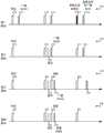
fig. 3A and 3B illustrate example transmit/receive timelines for respective first, second, third, fourth, fifth, and sixth base stations, in accordance with various aspects of the present disclosure;
FIG. 4 is a swim lane diagram illustrating a base station transmitting a synchronization signal, a primary system information block (MSIB) and another system information block (OSIB), in accordance with various aspects of the present disclosure;
FIG. 5 illustrates a Venn diagram (Venn Diagram) of respective coverage areas of a 5G wireless communication network, a first neighbor radio access technology (RAT; e.g., neighbor RAT 1), a second neighbor RAT (e.g., neighbor RAT 2), and a third neighbor RAT (e.g., neighbor RAT 3), in accordance with various aspects of the present disclosure;
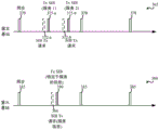
fig. 6 is a swim lane diagram illustrating a base station transmitting a synchronization signal, MSIB, and OSIB, in accordance with various aspects of the present disclosure;
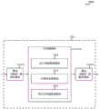
fig. 7 illustrates a block diagram of a UE for use in wireless communications, in accordance with various aspects of the present disclosure;
fig. 8 illustrates a block diagram of a UE for use in wireless communications, in accordance with various aspects of the present disclosure;
fig. 9 illustrates a block diagram of a UE for use in wireless communications, in accordance with various aspects of the present disclosure;
fig. 10 illustrates a block diagram of a UE for use in wireless communications, in accordance with various aspects of the present disclosure;
fig. 11 illustrates a block diagram of a UE for use in wireless communications, in accordance with various aspects of the present disclosure;
fig. 12 illustrates a block diagram of a UE for use in wireless communications, in accordance with various aspects of the disclosure;
fig. 13 illustrates a block diagram of a UE for use in wireless communications, in accordance with various aspects of the present disclosure;
Fig. 14 illustrates a block diagram of a UE for use in wireless communications, in accordance with various aspects of the present disclosure;
fig. 15 illustrates a block diagram of a UE for use in wireless communications, in accordance with various aspects of the present disclosure;
fig. 16 illustrates a block diagram of a base station for use in wireless communications, in accordance with various aspects of the disclosure;
fig. 17 illustrates a block diagram of a base station for use in wireless communications, in accordance with various aspects of the disclosure;
fig. 18 illustrates a block diagram of a base station for use in wireless communications, in accordance with various aspects of the disclosure;
fig. 19 illustrates a block diagram of a base station for use in wireless communications, in accordance with various aspects of the disclosure;
fig. 20 illustrates a block diagram of a base station for use in wireless communications, in accordance with various aspects of the disclosure;
fig. 21 illustrates a block diagram of a base station for use in wireless communications, in accordance with various aspects of the disclosure;
fig. 22 illustrates a block diagram of a base station for use in wireless communications, in accordance with various aspects of the disclosure;
fig. 23 illustrates a block diagram of a base station for use in wireless communications, in accordance with various aspects of the disclosure;
Fig. 24A illustrates a block diagram of a base station (e.g., a base station forming a portion or all of an eNB) for use in wireless communications, in accordance with various aspects of the disclosure;
fig. 24B illustrates a block diagram of a base station (e.g., a base station forming a portion or all of an eNB) for use in wireless communications, in accordance with various aspects of the disclosure;
fig. 25 is a block diagram illustrating a multiple-input multiple-output (MIMO) communication system including a base station and a UE, in accordance with various aspects of the present disclosure;
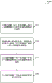
fig. 26 is a flow diagram illustrating an example of a method for wireless communication at a UE in accordance with various aspects of the disclosure;
fig. 27 is a flow diagram illustrating an example of a method for wireless communication at a UE in accordance with various aspects of the disclosure;
fig. 28 is a flow diagram illustrating an example of a method for wireless communication at a UE in accordance with various aspects of the disclosure;
fig. 29 is a flow diagram illustrating an example of a method for wireless communication at a base station in accordance with various aspects of the disclosure;
fig. 30 is a flow diagram illustrating an example of a method for wireless communication at a base station in accordance with various aspects of the disclosure;
Fig. 31 is a flow diagram illustrating an example of a method for wireless communication at a base station in accordance with various aspects of the disclosure;
fig. 32 is a flow diagram illustrating an example of a method for wireless communication at a base station in accordance with various aspects of the disclosure;
fig. 33 is a flow diagram illustrating an example of a method for wireless communication at a UE in accordance with various aspects of the disclosure;
fig. 34 is a flow diagram illustrating an example of a method for wireless communication at a UE in accordance with various aspects of the disclosure;
fig. 35 is a flow diagram illustrating an example of a method for wireless communication at a base station in accordance with various aspects of the disclosure;
fig. 36 is a flow diagram illustrating an example of a method for wireless communication at a base station in accordance with various aspects of the disclosure;
fig. 37 is a flow diagram illustrating an example of a method for wireless communication at a UE in accordance with various aspects of the disclosure;
fig. 38 is a flow diagram illustrating an example of a method for wireless communication at a UE in accordance with various aspects of the disclosure;
fig. 39 is a flow diagram illustrating an example of a method for wireless communication at a base station in accordance with various aspects of the disclosure;
Fig. 40 is a flow diagram illustrating an example of a method for wireless communication at a base station in accordance with various aspects of the disclosure;
fig. 41 is a flow diagram illustrating an example of a method for wireless communication at a UE in accordance with various aspects of the disclosure;
fig. 42 is a flow diagram illustrating an example of a method for wireless communication at a UE in accordance with various aspects of the disclosure;
fig. 43 is a flow diagram illustrating an example of a method for wireless communication at a base station in accordance with various aspects of the disclosure;
fig. 44 is a flow diagram illustrating an example of a method for wireless communication at a base station in accordance with various aspects of the disclosure;
fig. 45 is a flow diagram illustrating an example of a method for wireless communication at a base station in accordance with various aspects of the disclosure; and
fig. 46 is a flow diagram illustrating an example of a method for wireless communication at a base station in accordance with various aspects of the disclosure.
Detailed Description
The described features may be generally implemented in a wireless communication system having a User Equipment (UE) -centric network. In some cases, a UE-centric network may be deployed as follows: a plurality of base stations, wherein each of the one or more base stations is associated with a plurality of transceivers co-located with a base station server; a plurality of base stations, wherein each base station of the one or more base stations is associated with a plurality of remote transceivers (e.g., a plurality of Remote Radio Heads (RRHs)) located remotely from the base station server; a plurality of zones, wherein each zone is defined by a coverage area of one or more cells or base stations; or a combination thereof. In Time Division Duplex (TDD) systems with large antenna arrays, where the large antenna arrays may have limited coverage for broadcast channels (e.g., channels that broadcast synchronization signals and system information in a network-centric network), wireless communication systems with UE-centric networks may be advantageous in some aspects. As described in this disclosure, a wireless communication system with a UE-centric network may forgo broadcasting of system information. In some aspects, wireless communication systems with UE-centric networks may also be advantageous, as the broadcasting of system information by a base station may significantly contribute to the power consumption of the base station.
In one aspect of the disclosure, the wireless network may provide the system information through fixed periodic broadcast or broad beam transmission or in response to a request by the UE, for example. For example, the wireless network may broadcast (or broad beam transmit) a synchronization signal that indicates to UEs within a cell or region coverage area that system information is to be transmitted on a fixed periodic schedule or in response to a request transmitted by one or more UEs. In an "on-demand" system (where the UE requests transmission of system information), the system information may be sent as a periodic broadcast or broad beam transmission, as an aperiodic broadcast or broad beam transmission, or as an aperiodic unicast or narrow beam transmission.
In another aspect of the disclosure, a wireless network may provide service-specific system information. The service-specific system information may be provided as a broadcast or upon receiving a request from the UE. In an on-demand system, for example, a wireless network may broadcast (or broad beam transmit) a synchronization signal that indicates to UEs within a cell or region coverage area that service-specific system information is available for the UEs to request. Subsequently, the UE may send one or more requests for service-specific system information and may receive system information for the identified service. Alternatively, in a broadcast system, for example, a wireless network may broadcast (or broad-beam transmit) a synchronization signal indicating to UEs within a cell or area coverage area that service-specific system information is to be transmitted on a fixed periodic schedule based on the corresponding service. Thus, a UE that requires system information for a given service may learn from the synchronization signal one or more times during which the UE may listen to receive service-specific system information. The service-specific system information may be sent jointly or in separate transmissions corresponding to the services.
In another aspect of the disclosure, the wireless network may incrementally provide system information to the UE. For example, the wireless network may transmit primary system information followed by one or more transmissions of other system information (e.g., non-primary system information). For example, the primary system information may include system information that allows the UE to perform initial access of the network. The primary system information or other system information may be broadcast, broad beam transmitted, unicast, or narrow beam transmitted to multiple UEs. In some cases, primary system information or other system information may be transmitted on a fixed periodic schedule or in response to a request transmitted by one or more UEs. In various embodiments, the primary system information and other system information may be transmitted in the same, similar, or different manners.
In yet another aspect of the disclosure, the wireless network may indicate when system information changes or should be updated, for example. In this way, the UE need not update its stored system information each time it sends information, but may instead update its stored system information on an "as needed" basis. The UE may also initiate an update to its stored system information upon the occurrence of one or more events, such as: it is determined that the UE has moved a certain distance since its last update of stored system information, or that the UE has moved into a new zone.
The techniques described herein may be used for various wireless communication systems such as Code Division Multiple Access (CDMA) systems, time Division Multiple Access (TDMA) systems, frequency Division Multiple Access (FDMA) systems, orthogonal Frequency Division Multiple Access (OFDMA) systems, and single carrier frequency division multiple access (SC-FDMA) systems, among others. The terms "system" and "network" are often used interchangeably. A CDMA system may implement a radio technology such as CDMA2000, universal Terrestrial Radio Access (UTRA), and so on. CDMA2000 covers IS-2000, IS-95 and IS-856 standards. IS-2000 releases 0 and A are commonly referred to as CDMA2000 1X, etc. IS-856 (TIA-856) IS commonly referred to as CDMA2000 1xEV-DO, high Rate Packet Data (HRPD), etc. UTRA includes Wideband CDMA (WCDMA) and other variants of CDMA. TDMA systems may implement wireless technologies such as global system for mobile communications (GSM). OFDMA systems may implement methods such as Ultra Mobile Broadband (UMB), evolved UTRA (E-UTRA), IEEE 802.11 (Wi-Fi), IEEE 802.16 (WiMAX), IEEE 802.20, flash OFDM TM Etc. wireless technologies. UTRA and E-UTRA are part of the Universal Mobile Telecommunications System (UMTS). Long Term Evolution (LTE) and LTE-advanced (LTE-A) are new versions of UMTS that use E-UTRA. UTRA, E-UTRA, UMTS, LTE-A, and GSM are described in documents from an organization entitled "third Generation partnership project" (3 GPP). CDMA2000 and UMB are described in documents from an organization named "third generation partnership project 2" (3 GPP 2). The techniques described herein may be used for the above-mentioned systems and wireless technologies, as well as other systems and wireless technologies, including cellular (e.g., LTE) communications over a shared radio frequency band. Although the following description describes an LTE/LTE-a system for purposes of example, and LTE terminology is used in much of the description, the techniques are applicable beyond LTE/LTE-a applications (e.g., applicable to 5G networks or other next generation communication systems).
The following description provides examples, and does not limit the scope, applicability, or examples set forth in the claims. Changes may be made in the function and arrangement of elements discussed without departing from the scope of the disclosure. Various examples may omit, substitute, or add various procedures or components as appropriate. For example, the described methods may be performed in an order different than that described, and various steps may be added, omitted, or combined. Furthermore, features described with respect to some examples may be combined into other examples.
Fig. 1 illustrates an example of a wireless communication system 100 in accordance with various aspects of the disclosure. The wireless communication system 100 may include one or more base stations 105, one or more UEs 115, and a core network 130. The core network 130 may provide user authentication, access authorization, tracking, internet Protocol (IP) connectivity, and other access, routing, or mobility functions. The base station 105 may interface with the core network 130 over a backhaul link 132 (e.g., S1, etc.). The base station 105 may perform radio configuration and scheduling for communication with the UE 115 or may operate under the control of a base station controller (not shown). In various examples, the base stations 105 can communicate with each other directly or indirectly (e.g., through the core network 130) through backhaul links 134 (e.g., X1, etc.), which backhaul links 134 can be wired or wireless communication links.
The base station 105 may communicate wirelessly with the UE 115 via one or more antennas. In some examples, the one or more antennas may include one or more base station antennas (and transceivers) collocated with the base station server and/or one or more RRH antennas (and transceivers) located remotely from the base station server. Each of the base stations 105 may provide communication coverage for a respective geographic coverage area 110. In some examples, the base station 105 may be referred to as a base station transceiver, a wireless base station, an access point, a wireless transceiver, a node B, an evolved node B (eNB), a Home Node B (HNB), a home evolved node B, or some other suitable terminology. The geographic coverage area 110 for a base station 105 can be divided into sectors (not shown), which form only a portion of the coverage area. The geographic coverage area 110 of one or more base stations 105 may define a zone of the wireless communication system 100. The wireless communication system 100 may include different types of base stations 105 (e.g., macro cell base stations or small cell base stations). For different technologies, there may be overlapping geographic coverage areas 110.
In some examples, the wireless communication system 100 may be or include an LTE or LTE-a network. The wireless communication system 100 may also be or include a next generation network, such as a 5G wireless communication network. In LTE/LTE-a and 5G networks, the term evolved node B (eNB) may be used generally to describe a base station 105, while the term UE may be used generally to describe a UE 115. The wireless communication system 100 may be a heterogeneous LTE/LTE-a or 5G network, where different types of enbs provide coverage for various geographic areas. For example, each eNB or base station 105 may provide communication coverage for a macro cell, a small cell, or other type of cell. The term "cell" is a 3GPP term that can be used to describe a base station, a carrier or component carrier associated with a base station, or a coverage area (e.g., sector, etc.) of a carrier or base station, depending on the context.
A macro cell may typically cover a relatively large geographic area (e.g., several kilometers in radius) and may allow unrestricted access by UEs 115 with service subscriptions with the network provider. A small cell may include a lower power base station, as compared to a macro cell, which may operate in the same or different (e.g., licensed, unlicensed, etc.) frequency band as the macro cell. The small cells may include pico cells, femto cells, and micro cells according to various examples. For example, a pico cell may cover a relatively small geographic area and may allow unrestricted access by UEs 115 with service subscriptions with the network provider. A femto cell may also cover a small geographic area (e.g., a residence) and may provide restricted access by UEs 115 with association with the femto cell (e.g., UEs 115 in a Closed Subscriber Group (CSG), UEs 115 for users in the residence, etc.). The eNB for the macro cell may be referred to as a macro eNB. An eNB for a small cell may be referred to as a small cell eNB, pico eNB, femto eNB, or home eNB. An eNB may support one or more (e.g., two, three, four, etc.) cells.
The communication network that may accommodate some of the various disclosed examples may be a packet-based network operating according to a layered protocol stack, and the data in the user plane may be IP-based. The Radio Link Control (RLC) layer may perform packet segmentation and reassembly to communicate over logical channels. The MAC layer may perform priority processing and multiplexing of logical channels into transport channels. The MAC layer may also use HARQ to provide transmissions at the MAC layer to improve link efficiency. In the control plane, a Radio Resource Control (RRC) protocol layer may provide establishment, configuration, and maintenance of RRC connections between the UE 115 and the base station 105. The RRC protocol layer may also be used for core network 130 support of radio bearers for user plane data. At the Physical (PHY) layer, transport channels may be mapped to physical channels.
The wireless communication link 125 shown in the wireless communication system 100 may carry Uplink (UL) transmissions from the UE 115 to the base station 105, or Downlink (DL) transmissions from the base station 105 to the UE 115. Downlink transmissions may also be referred to as forward link transmissions, and uplink transmissions may also be referred to as reverse link transmissions. Each wireless communication link 125 may include one or more carriers, where each carrier may be a signal composed of multiple subcarriers (e.g., waveform signals of different frequencies) modulated according to the various wireless technologies described above. Each modulated signal may be transmitted on a different subcarrier and may carry control information (e.g., reference signals, control channels, etc.), overhead information, user data, and so on. The wireless communication link 125 may transmit bi-directional communications using Frequency Division Duplex (FDD) operation (e.g., using paired spectrum resources) or TDD operation (e.g., using unpaired spectrum resources). A frame structure for FDD (e.g., frame structure type 1) and a frame structure for TDD (e.g., frame structure type 2) may be defined.
In some embodiments of the wireless communication system 100, the base station 105 or the UE 115 may include multiple antennas for employing an antenna diversity scheme to improve the quality and reliability of communications between the base station 105 and the UE 115. Additionally or alternatively, the base station 105 or UE 115 may employ multiple-input multiple-output (MIMO) techniques (e.g., any MIMO that is not massive MIMO (e.g., multiple-antenna MIMO and multi-user MIMO) techniques or massive MIMO techniques) that may utilize a multipath environment to transmit multiple spatial layers carrying the same or different encoded data.
The wireless communication system 100 may support operation on multiple cells or carriers (a feature referred to as Carrier Aggregation (CA) or multi-carrier operation). The carriers may also be referred to as Component Carriers (CCs), layers, channels, and the like. The terms "carrier," "component carrier," "cell," and "channel" are used interchangeably herein. A UE 115 may be configured with multiple downlink CCs and one or more uplink CCs for carrier aggregation. Carrier aggregation may be used with both FDD and TDD component carriers.
In some embodiments of the wireless communication system 100, the wireless communication system 100 may have a UE-centric network. On the network side, the base station 105 may broadcast a periodic synchronization (sync) signal. The UE 115 may receive the synchronization signal, acquire timing of the network from the synchronization signal, and transmit a pilot signal in response to acquiring the timing of the network. The pilot signals transmitted by the UE 115 may be received simultaneously by multiple cells (e.g., base stations 105) within the network. Each of the plurality of cells may measure the strength of the pilot signal, and the network (e.g., one or more of the base stations 105, each base station 105 communicating with the UE 115 via one or more centrally located transceivers and/or RRHs, and/or a central node within the core network 130) may determine a serving cell for the UE 115. As the UE 115 continues to transmit pilot signals, the network may handover the UE 115 from one serving cell to another, with or without notification of the UE 115. System Information (SI) may be transmitted to UEs 115 in a broadcast mode (where the base station 105 transmits SI regardless of whether the SI is requested or needed by any UE 115 within the coverage area 110 of the base station 105) or in an on-demand mode (where the base station 105 transmits SI in response to receiving a request for SI from one or more UEs 115, where the request may be included in the pilot signals of the UEs 115 or may be the pilot signals of the UEs 115). When transmitting SI in on-demand mode, the base station 105 may forgo broadcasting the SI, which may save power.
Fig. 2 illustrates an example of UE movement within a wireless communication system 200, in accordance with various aspects of the present disclosure. More specifically, fig. 2 illustrates the UE 115-a as the UE 115-a moves to various points (e.g., point a, point B, and point C) within the coverage areas 110-a and 110-B of the respective first and second base stations 105-a and 105-B. In some examples, the UE 115-a may be an example of one or more aspects of the UE 115 described with reference to fig. 1, and the first base station 105-a and the second base station 105-b may be examples of one or more aspects of the base station 105 described with reference to fig. 1.
By way of example, the UE 115-a may be powered up within the coverage area 110-a of the first base station 105-a and may perform initial acquisition of SI within the coverage area 110-a of the first base station 105-a. In some examples, UE 115-a may perform initial acquisition of SI by receiving an instance of a periodic synchronization signal from first base station 105-a; determining where and when to listen to the first base station 105-a for the SI broadcast based on the synchronization signal; and then listen and receive the SI broadcast by the first base station 105-a. In other examples, the UE 115-a may perform initial acquisition of the SI by receiving an instance of a periodic synchronization signal from the first base station 105-a; determining from the synchronization signal where and when to listen to the first base station 105-a for the broadcast of the SI, and in some cases, where and when to send a request for the SI; sending a request for SI; and then listen and receive the SI broadcast by the first base station 105-a. In other examples, the UE 115-a may perform initial acquisition of the service-specific SI by determining from the periodic synchronization signal received from the first base station 105-a that the service-specific SI is available to be received via broadcast or via request, and then listen for or request the service-specific SI.
While still at point a, the UE 115-a may determine to reacquire the SI based on the expiration of the dynamic SI or based on the time elapsed since the last acquisition of the SI. The UE 115-a may also reacquire the SI at point a after receiving an instance of the synchronization signal indicating that the SI has changed. In other embodiments, the UE 115-a may not reacquire the SI at point a.
When moving from point a to point B, the UE 115-a may determine to reacquire the SI. For example, the UE 115-a may determine to reacquire the SI based on its motion, based on the distance between point a and point B, based on the expiration of a dynamic SI, or based on the time elapsed since the last acquisition of the SI. The UE 115-a may also reacquire the SI at point B after receiving an instance of the synchronization signal indicating that the SI has changed. In other embodiments, the UE 115-a may not reacquire the SI at point B.
When moving from point B to point C and into the coverage area 110-B of the second base station 105-B, the UE 115-a may perform initial acquisition of SI from the second base station 105-B. In other embodiments, the UE 115-a does not need to acquire the SI from the second base station 105-B unless one of the reasons for reacquiring the SI at point B arises. In some cases, SI may not be acquired at the coverage area 110-b because the first coverage area 110-a and the second coverage area 110-b are configured to operate as members of a common zone such that data transmission services for the UE 115-a are provided by the network.
Fig. 2 illustrates that SI may be acquired during various UE mobility states and for various reasons. For example, the SI may be acquired when the UE is not attached to the network (e.g., as part of an initial acquisition of the SI). The SI may also be acquired after the UE attaches to the network and when the UE is stationary (e.g., because a timer or the SI has expired, or because the network has indicated (e.g., in the instance of a synchronization signal or in a paging message) that the SI has changed). SI may also be acquired after the UE attaches to the network and when the UE moves (e.g., for any of the reasons to reacquire SI when the UE is stationary, because the UE has moved to a new location, because the UE has moved some distance from a previous location where SI was acquired, or because the UE has moved to the coverage area of a new base station or cell).
Fig. 3A and 3B illustrate example transmit/receive timelines 305, 320, 335, 350, 365, and 380 for respective first, second, third, fourth, fifth, and sixth base stations, in accordance with various aspects of the present disclosure. The transmissions of the base station may be received by one or more UEs and used by the UEs at initial SI acquisition (e.g., SI acquisition during system selection or movement to a new cell or region) or at SI change acquisition (e.g., when SI changes or when dynamic SI expires). In some examples, the base stations may belong to respective different cells or regions of a wireless communication system, such as different cells or regions of the wireless communication system 100 or 200 described with reference to fig. 1 or 2. In some examples, the first, second, third, fourth, fifth, and sixth base stations may be examples of one or more aspects of the base station 105 described with reference to fig. 1.
As shown in fig. 3A and 3B, each of the base stations may transmit a periodic synchronization signal (Sync) 310, 325, 340, 355, 370, or 385. In the example of fig. 3A, each of the base stations also transmits a periodic or on-demand primary system information block (MSIB) 315, 330, 342, or 358. In some cases, the instance of the synchronization signal and the instance of the MSIB together may provide information equivalent to information included in the LTE/LTE-a Master Information Block (MIB), system information block 1 (SIB 1), and SIB 2. In the example of fig. 3B, each of the base stations transmits a service- specific SIB 375, 390.
In some embodiments, the synchronization signals transmitted by the base stations may be common (e.g., non-cell-specific) to multiple cells within the access network (e.g., multiple cells within a zone) and may be broadcast from each of the multiple cells (e.g., from each of the multiple base stations in a cell) in a Single Frequency Network (SFN). The synchronization signal need not include a cell identifier. In some embodiments, the synchronization signal may have a relatively short duration or may be transmitted relatively infrequently. For example, the synchronization signal may have a duration of one symbol and be transmitted once every ten seconds. In other examples, the synchronization signal may be transmitted more frequently, such as once per radio frame. In some embodiments, an instance of the synchronization signal may carry several bits of information. More specifically, and in some embodiments, instances of the synchronization signal may include information such as: the UE may be used to determine whether to request information for subsequently transmitted MSIBs, the UE may be used to determine where and when to request subsequently transmitted MSIBs (e.g., frequency and timing information for transmitting MSIB transmission requests), the UE may be used to determine where and when information (e.g., channel, frequency, and/or timing information) for subsequently transmitted MSIBs may be received, information about when to indicate when an MSIB changes, or information that the UE may be used to distinguish a cell or region transmitting a synchronization signal from one or more other cells or regions (e.g., from neighbor cells or regions). In some embodiments, examples of the synchronization signal may include: the UE may be used to determine whether to request subsequently transmitted information of the service-specific SIB, where and when to request subsequently transmitted information of the service-specific SIB (e.g., frequency and timing information for transmitting the service-specific SIB transmission request), or where and when to receive subsequently transmitted information of the service-specific SIB (e.g., channel, frequency, and/or timing information).
In some embodiments, the synchronization signal may indicate a PHY layer channel on which the MSIB or service-specific SIB transmission request is to be sent, or a special PHY layer channel for sending the MSIB or service-specific SIB transmission request under certain conditions. In some cases, the synchronization signal may also indicate how to send the MSIB or service-specific SIB transmission request (e.g., the format used in sending the MSIB or service-specific SIB transmission request), or how to send the MSIB or service-specific SIB transmission request in certain situations. In other embodiments, the synchronization signal may specify fewer parameters for transmitting the MSIB or service-specific SIB transmission request. However, this may necessitate that the base station in certain conditions (or always) listen to the MSIB or service-specific SIB transmission request, which may impact UE relay energy efficiency.
The UE may receive an instance of the synchronization signal and acquire timing of the access network based on the synchronization signal. In response to acquiring the timing of the access network, the UE may transmit a pilot signal. The pilot signal may be received simultaneously by multiple cells within the access network (e.g., multiple cells within a region of the access network). In some embodiments, the pilot signal may include a spatial signature (e.g., a Sounding Reference Signal (SRS)). In some embodiments, the pilot signal may be transmitted in the MSIB transmission request occasion indicated by the instance of the synchronization signal. In some embodiments, the pilot signal may be transmitted using a predetermined random sequence or a UE generated random sequence, which may be used by the access network (e.g., a base station of the access network) to temporarily identify the UE during the initial acquisition process. In some embodiments, the pilot signal may be or include an MSIB transmission request.
The MSIB 315, 330, 342, or 358 may indicate where and when the UE may establish a connection with the access network. The MSIB may include information such as: information identifying an access network, cell or region; information indicating whether the UE is allowed (or should) use the access network; or information indicating how the UE may use the access network (e.g., information indicating how the UE may use the access network when the UE powers up or when the UE moves to a new cell or region after detecting a failure (QoS) or Radio Link Failure (RLF) event). The information identifying the access network, cell or zone may include a Public Land Mobile Network (PLMN) Identifier (ID), a Tracking Area Code (TAC), a cell identifier (cell ID) or a zone identifier (zone ID). The information indicating whether the UE is allowed (or should) use the access network may include system selection or access restriction information (e.g., radio quality information, congestion avoidance information, or Closed Subscriber Group (CSG) information) for a cell or region. The information indicating how the UE may use the access network may include access configuration information (e.g., random Access Channel (RACH) information, or UE timer and constant information). The MSIB may also include PHY layer configuration information such as: physical Random Access Channel (PRACH) information, physical Downlink Shared Channel (PDSCH) information, physical Downlink Control Channel (PDCCH) information, physical Uplink Shared Channel (PUSCH) information, physical Uplink Control Channel (PUCCH) information, and SRS information, or other information that may be used to access the PHY layer of the wireless communication system.
The service- specific SIBs 375, 390 may indicate where and when the UE may establish a connection with the access network for a particular service. For example, the specific service may include an energy efficient service, a high reliability service, a low latency service, a broadcast service, or a small data service. These services may require additional SI (e.g., SI not included in the MSIB) in order to allow the UE to access the network. For example, multimedia Broadcast Multicast Service (MBMS) in LTE may have additional configuration information in SIB13 related to accessing MBMS. Additionally, as radio access technologies evolve, it may be desirable to enable not only the transmission of additional SI for a particular service, but also the transmission of different configurations of the same service-specific SI to improve the performance of different services. For example, the additional service-specific SI may include information about identifying the access network and the cell (e.g., PLMN ID, TAC, or cell ID). The additional service-specific SI may also include information for the cell and access restrictions (including radio quality, congestion avoidance, CSG). The additional service-specific SI may also include information about the access configuration (RACH, UE timer and restrictions and other 5G network equivalents).
For example, the service-specific SIB may include information to enable more efficient access configurations and longer validity timers for SI in a Wide Area Network (WAN) internet of everything (IOE), where lower power operation may be desirable since IOE devices may not be connected with the network until after a long sleep period. Additionally, services such as WAN IOEs may include different information in the MSIB to avoid requiring IOE devices to read additional SI.
Turning now to the transmit/receive timeline 305 of the first base station (in fig. 3A), the first base station may transmit a periodic synchronization signal 310, as previously described. Upon receiving an instance of the synchronization signal, the UE that needs to perform initial acquisition may identify an access network associated with the first base station (and in some cases, information for distinguishing the first base station, its cell, or its region from other base stations, cells, or regions); determining whether the UE can (or should) acquire the SI of the access network; and determining how the UE may acquire the SI of the access network. When determining how the UE may acquire the SI of the access network, the UE may determine, via signaling associated with the synchronization signal, that the first base station transmits the MSIB 315 in a broadcast (or wide beam) transmission mode with fixed periodic signaling. The UE may also identify a time for receiving the MSIB transmission based on the synchronization signal. A UE that does not need to perform initial acquisition may determine whether it has moved to a new cell or a new region based on the synchronization signal. When the UE determines that it has moved to a new cell or a new region, the UE may use information included in the synchronization signal to acquire new SI or updated SI from the new cell or the new region.
Referring to the second base station's transmit/receive timeline 320 (of fig. 3A), the second base station may transmit a periodic synchronization signal 325, as previously described. Upon receiving an instance of the synchronization signal, the UE that needs to perform initial acquisition may identify an access network associated with the second base station (and in some cases, information for distinguishing the second base station, its cell, or its region from other base stations, cells, or regions); determining whether the UE can (or should) acquire the SI of the access network; and determining how the UE may acquire the SI of the access network. When determining how the UE may acquire the SI of the access network, the UE may determine, via signaling associated with the synchronization signal, that the second base station transmits the MSIB 330 in an on-demand broadcast (or wide beam) transmission mode using periodic signaling (i.e., the second base station will begin broadcast (or wide beam) transmission of the MSIB using periodic scheduling when receiving an MSIB transmission request signal 332 from the UE). The UE may also identify where and when to send the MSIB transmission request and the time to receive the MSIB transmission based on the synchronization signal. A UE that does not need to perform initial acquisition may determine whether it has moved to a new cell or a new region based on the synchronization signal. When the UE determines that it has moved to a new cell or a new region, the UE may use information included in the synchronization signal to acquire new SI or updated SI from the new cell or the new region.
Referring to the third base station's transmit/receive timeline 335 (of fig. 3A), the third base station may transmit a periodic synchronization signal 340, as previously described. Upon receiving an instance of the synchronization signal, the UE that needs to perform initial acquisition may identify an access network associated with the third base station (and in some cases, information for distinguishing the third base station, its cell, or its region from other base stations, cells, or regions); determining whether the UE can (or should) acquire the SI of the access network; and determining how the UE may acquire the SI of the access network. When determining how the UE may acquire the SI of the access network, the UE may determine, via signaling associated with the synchronization signal, that the third base station transmits the MSIB 342 in an on-demand broadcast (or wide beam) transmission mode using aperiodic signaling (i.e., the third base station will schedule broadcast (or wide beam) transmission of the MSIB when receiving the MSIB transmission request signal 345 from the UE, and the UE may monitor a scheduling channel (e.g., PDCCH) for scheduling information (scheduled.) 348 to determine when the MSIB will be transmitted). The UE may also identify where and when to send the MSIB transmission request based on the synchronization signal. A UE that does not need to perform initial acquisition may determine whether it has moved to a new cell or a new region based on the synchronization signal. When the UE determines that it has moved to a new cell or a new region, the UE may use information included in the synchronization signal to acquire new SI or updated SI from the new cell or the new region.
Referring to the fourth base station's transmit/receive timeline 350 (of fig. 3A), the fourth base station may transmit a periodic synchronization signal 355, as previously described. Upon receiving an instance of the synchronization signal, the UE that needs to perform initial acquisition may identify an access network associated with the fourth base station (and in some cases, information for distinguishing the fourth base station, its cell, or its region from other base stations, cells, or regions); determining whether the UE can (or should) acquire the SI of the access network; and determining how the UE may acquire the SI of the access network. When determining how the UE may acquire the SI of the access network, the UE may determine, via signaling associated with the synchronization signal, that the fourth base station transmits the MSIB 358 in a unicast (or narrowbeam) transmission mode (i.e., the fourth base station will schedule unicast (or narrowbeam) transmission of the MSIB when the MSIB transmission request signal 360 is received from the UE, and the UE may monitor a scheduling channel (e.g., PDCCH) for scheduling information (scheduled.) 362 to determine when the MSIB will be transmitted). The UE may also identify where and when to send the MSIB transmission request based on the synchronization signal. A UE that does not need to perform initial acquisition may determine whether it has moved to a new cell or a new region based on the synchronization signal. When the UE determines that it has moved to a new cell or a new region, the UE may use information included in the synchronization signal to acquire new SI or updated SI from the new cell or the new region.
In each of the transmission/ reception timelines 305, 320, 335, and 350 shown in fig. 3A, the base station transmits the MSIB 315, 330, 342, or 358. In some examples. The UE may receive the MSIB by: the method includes monitoring a system information radio network temporary identifier (SI-RNTI) on a common physical control channel (e.g., PDCCH), decoding a downlink allocation message associated with the SI-RNTI, and receiving the MSIB on a shared channel (e.g., PDSCH) according to information contained in the downlink allocation message. Alternatively, when a radio network temporary identifier (RNTI; e.g., a cell RNTI (C-RNTI) or a region RNTI (Z-RNTI)) is allocated for the UE, the UE may monitor the RNTI on a common physical control channel (e.g., PDCCH), decode a downlink allocation message associated with the RNTI, and receive the MSIB on a shared channel (e.g., PDSCH) according to information contained in the downlink allocation message. In another alternative, the UE may monitor the SI-RNTI to receive the broadcast SI, while the UE may also receive the unicast SI using an RNTI (e.g., C-RNTI or zone RNTI) specifically allocated for the UE.
While camped on a cell, the UE may decode at least a portion of each instance of a periodic synchronization signal transmitted by the cell to determine whether the information included in the MSIB has changed. Alternatively, the UE may decode at least a portion of each nth instance of the periodic synchronization signal, or may decode at least a portion of an instance of the periodic synchronization signal upon the occurrence of one or more events. The decoded portion of the subsequent instance of the synchronization signal may include information (e.g., a modification flag or value tag) that may be sent to indicate whether the SI for the cell has changed. When it is determined that the SI for the cell has changed (e.g., in the transmit/receive timeline 305, after receiving the instance 310-a of the synchronization signal 310), the UE may request and/or receive an MSIB (e.g., MSIB 315-a) with the changed SI.
As the UE moves within the coverage area of the wireless communication system, the UE may detect synchronization signals of different cells (or regions), such as the different cells (or coverage areas 110, 110-a, 110-b, or regions) described with reference to fig. 1 or 2, or the different cells (or base stations or regions) described with reference to fig. 3A. When a synchronization signal of a cell or region is detected, the UE may compare a Cell Global Identity (CGI) (or Base Station Identity Code (BSIC) or region identity) corresponding to the cell (or base station or region) for which the UE last acquired the SI with the CGI (or BSIC or region identity) associated with the synchronization signal to determine whether the UE has detected a new synchronization signal (e.g., a synchronization signal of a different cell, base station, or region).
The on-demand transmission of the MSIB may be UE-initiated (e.g., during initial access) or access network-initiated (e.g., when information included in the MSIB changes or when a special SIB is sent). In some cases, a base station transmitting and receiving signals according to one of the transmit/receive timelines 305, 320, 335, or 350 may switch transmit/receive modes, and thus from one transmit/receive timeline to another. The handover may be made, for example, based on network load or congestion status. In some embodiments, the base station may also or alternatively switch between an "on demand unicast (or narrow beam)" mode and an "always on broadcast (or wide beam)" mode for MSIB transmission. In some examples, a base station may signal one or more modes in which it operates in its periodic synchronization signal.
Turning now to the transmit/receive timeline 365 of the fifth base station (of fig. 3B), the fifth base station may transmit a service-specific periodic synchronization signal 370. The service-specific periodic synchronization signal 370 may be an example of one of the synchronization signals 310, 325, 340, 355, except that the service-specific periodic synchronization signal 370 may include an indication that a service-specific SI is available. The service-specific periodic synchronization signal 370 may also include information about which services the service-specific SI is available for. Alternatively, the service-specific periodic synchronization signal 370 may include information about when scheduling of service-specific SI for different services may be requested or transmitted. In one example, a certain service-specific SI may not be transmitted in every synchronization signal period. For example, a synchronized MBMS service may only require service-specific SIBs to be transmitted in the order of seconds, and thus may not be available during each synchronization signal period. Upon receiving the instances of the synchronization signal, the UE may determine that the UE needs one or more of the available service-specific SIs. The ue may send a SIB transmission (Tx) request 372 according to the service-specific periodic synchronization signal 370. The UE may send a SIB Tx request 372-a for transmission of SI related to a particular service (e.g., service 1) and may then send a SIB Tx request 372-b for transmission of SI related to a different particular service (e.g., service 2). In response to receiving the SIB Tx request 372, one or more base stations may transmit a service-specific SIB 375 to the UE. The fifth base station may transmit the service-specific SIB 375-a in response to the SIB Tx request 372-a and may also transmit the service-specific SIB 375-b in response to the SIB Tx request 372-b. Alternatively, the fifth base station may broadcast the service-specific SIB 375 without waiting for the SIB Tx request 372. In this alternative, the service-specific periodic synchronization signal 370 may indicate when and on what resources the UE may listen to receive the service-specific SIB 375.
Referring to the sixth base station's transmit/receive timeline 380 (of fig. 3B), the sixth base station may transmit a service-specific periodic synchronization signal 385. The service-specific periodic synchronization signal 385 may be an example of one of the synchronization signals 310, 325, 340, 355, except that the service-specific periodic synchronization signal 385 may include an indication that a service-specific SI is available. However, the service-specific periodic synchronization signal 385 may not indicate the actual service for which the SI is available. Alternatively, in the transmit/receive timeline 380, the UE is required to explicitly identify the service for which SI is desired in the SIB Tx request 388. The service-specific synchronization signal 385 may include information about when and on what resources the UE may send its SIB Tx request 388. Thus, upon receiving an instance of the synchronization signal, the UE may determine that the UE needs one or more of the available service-specific SIs. The ue may send a SIB Tx request 388 identifying the requested SI according to the service specific periodic synchronization signal 385. In response to receiving the SIB Tx request 388, the sixth base station may send the service-specific SIB 390 to the UE. The service-specific SIB 390 may be transmitted together or jointly in a single transmission or may be transmitted separately.
Based on the service indicated in the service-specific periodic synchronization signals 370, 385 or SIB Tx requests 372, 388, the base station may transmit the service- specific SIB 375, 390 to the UE. The service- specific SIBs 375, 390 may include service-specific configurations, such as SI parameters specifically configured to improve service or meet service requirements. For example, the service-specific configuration may include a validity timer or SI reading requirements that require the IOE device to reacquire SI after the IOE device wakes up from a Power Saving Mode (PSM) or deep sleep. For example, an IOE device may acquire an SI with a particular value tag and may then transition to PSM for an extended period of time (e.g., as a result of the device being an IOE device). By the time the IOE device wakes up, the SI may have changed more than once. In fact, it is even possible that the SI will have changed by a number of times equal to the number of values available to the SI value tag, which means that the SI acquired by the IOE device may coincidentally have the same value tag as the value tag of the SI detected by the IOE device when the IOE device wakes up. If the IOE device relies on the SI value tag to determine whether the IOE device will acquire the updated SI, the IOE device may determine that a new SI will not be acquired. However, a validity timer or SI reading requirement may be used to ensure that the IOE device acquires the updated SI, even though the SI value tag will indicate that the updated SI is not to be acquired. For example, a validity timer or SI reading requirement may require the IOE device to reacquire SI after expiration of a specified time, which in one example may be equal to a PSM time of the IOE device. Alternatively, the validity timer may be received as part of the service-specific configuration of the service- specific SIB 375, 390. In this case, the validity timer may be set to a duration that requires the IOE device to reacquire SI at least once during each SI value tag wrap. Thus, if the operator changes the SI once every ten minutes, and the SI value tag ranges from 0-31, the validity timer may be set to 320 minutes. The validity timer may also be based on other factors. The validity timer or SI reading requirement may be communicated to the IOE device in the service- specific SIB 375, 390 as part of the service-specific configuration.
As one example, in some LTE standards, the UE may consider the stored SI to be invalid after three hours from the time the SI is confirmed to be valid. While certain exceptions may apply in LTE (e.g., CSG-PhyCellIdRange, although the exception is due to the fact that updated SI may not be available when the UE is not camped on a CSG cell), the three hour requirement may not apply to many devices, including IOE devices that may enter PSM or through which SI value tags cycle at different frequencies. Thus, for WAN IOE devices, the validity timer may be extended or decreased for SI related to the WAN IOE network.
The service- specific SIBs 375, 390 may also include service-specific information, such as service-specific parameters similar to those defined for MBMS. For WAN IOE devices, service-specific configurations may be included in a single SIB, so that the IOE device does not need to send multiple requests to incrementally receive any necessary SI.
Additionally, when supporting multiple service-specific SIs corresponding to multiple services, the network may use different transmission modes for each service to support transmission of the SI. Thus, and for example, WAN IOE SI may be broadcast periodically, while nominal SI may be sent on demand.
In an on-demand scenario, if the UE requests SI for more than one service in SIB Tx requests 372, 388, the responding base station may provide separate SI for each service or common SI for all desired services, where, for example, the base station may apply the most stringent configuration values to the parameters based on the service requirements for each requested service.
In addition to the periodic or on-demand MSIB, the base station may transmit one or more periodic or on-demand Other SIBs (OSIBs). The OSIB may include information equivalent to information included in one or more of the LTE/LTE-a SIBs other than SIB1 or SIB2 (e.g., information to enable an operator to manage system selection intra-Radio Access Technology (RAT) or inter-RAT information, information to discover availability and configuration of one or more services for the UE). An example transmission of OSIB is shown in fig. 4.
Fig. 4 is a swim lane diagram illustrating a base station 105-c transmitting a synchronization signal, MSIB, and OSIB, in accordance with various aspects of the present disclosure. Figure 4 also illustrates the request and receipt of the MSIB and OSIB by a UE115-b performing initial acquisition of the SI of the access network. In some examples, the base station may incorporate aspects of one or more of the base stations described with reference to fig. 1 or 2. Similarly, the UE115-b may incorporate aspects of one or more of the UEs 115 described with reference to fig. 1 or 2.
At 405, the base station 105-c may transmit an instance of a periodic synchronization signal, as described with reference to fig. 3A. UE 115-b may receive the instance of the synchronization signal and, at block 410, process the instance of the synchronization signal and determine that it needs to send an MSIB transmission request at 415 to obtain the MSIB from base station 105-c. The UE 115-b may also determine where and when to send the MSIB transmission request and where and when to expect transmission of the MSIB by the base station 105-c based on the instance of the synchronization signal.
At 420, base station 105-c may transmit the MSIB. UE 115-b may receive the MSIB and process the information included in the MSIB at block 425. The UE 115-b may also and optionally prepare an OSIB transmission request. In some examples, an optional OSIB transmission request may be prepared (e.g., at block 425) and sent (e.g., at 430) when the UE 115-b has not previously acquired SI from the cell or region in which the base station 105-c is operating, or when the buffered SI for the cell or region expires, or when the UE determines that the SI for the cell or region has changed (e.g., from a synchronization signal, from information in the MSIB that signals the change in SI, or from a paging message), or when the UE determines (e.g., during RRC _ IDLE) that it is in a location where a new SI may be provided (e.g., a location where a new neighbor cell list equivalent information may be provided, or a location where new Global Positioning System (GPS) assistance information may be provided). In some cases, the OSIB transmission request may indicate what OSIB information is being requested. For example, the UE 115-b may indicate in the OSIB transmission request what SI (e.g., what type of SI or what SI) the UE wants to receive. In some examples, a single OSIB transmission request 430 may be sent, and the single OSIB transmission request 430 may indicate one or more elements of other SIs that the UE wants to receive (e.g., a binary value may be set to TRUE for each element of other SIs that the UE wants to receive). In other examples, the UE 115-b may request some type of other SI in different OSIB transmission requests, and the UE may send multiple OSIB transmission requests to the base station.
The base station 105-c may receive the OSIB transmission request(s) and, at block 435, prepare one or more OSIBs for transmission to the UE at 440 or 445. In some embodiments, the base station may prepare one or more OSIBs including the SI requested by the UE in the OSIB transmission request. Additionally or alternatively, base station 105-c (and/or another network node with which the base station communicates) may determine what SI should be sent to UE 115-b in the OSIB. The base station 105-c and/or other network nodes may determine what SI to send to the UE 115-b based on, for example, the UE identity that the base station has acquired for the UE, the UE type, capability information, or other known information about the UE (and potentially acquired from the UE). In this way, the amount of SI sent to the UE 115-b may be optimized, which may help to save power, release resources, and so on.
As indicated previously, the OSIB may include information equivalent to information included in one or more of the LTE/LTE-a SIBs other than SIB1 or SIB2 (e.g., information to enable an operator to manage system selection intra-RAT or inter-RAT information, information to discover availability and configuration of one or more services for the UE). The information included in the OSIB may be numbered and organized based on the SI function to enable the base station to deliver information to the UE based on a subset of the UE functionality, based on the UE capabilities, or based on the UE service requirements (e.g., the base station may not deliver MBMS information to the UE when the UE is not capable of using MBMS services). In some cases, the information included in the OSIB may be numbered and organized the same as or similar to the information included in the LTE/LTE-a SIB.
The information included in the OSIB may be organized such that it may be efficiently received and processed by the UE. For example, the information may be organized such that the UE may read the information as infrequently as possible. In some embodiments, the information may be based on a range of information; whether it is applied system-wide, within a constellation, per cell, or per region based on the information; a duration of time to remain valid (e.g., a validity time) based on the information; or organized based on whether the information is semi-static or dynamic. When the information changes very dynamically, the information may be organized such that it may be transmitted with reduced latency.
The on-demand transmission of the OSIB may be initiated by the UE (e.g., during initial access) or by the access network (e.g., when information included in the OSIB changes or when a dedicated SIB is sent).
As previously described, in some cases, a base station may switch between an "on-demand unicast (or narrow beam)" mode and an "always on broadcast (or wide beam)" or "on-demand broadcast (or wide beam)" mode for MSIB transmission. The base station may also switch between an "on demand unicast (or narrow beam)" mode and an "always on broadcast (or wide beam)" or "on demand broadcast (or wide beam)" mode for OSIB transmissions. For "always on broadcast (or wide beam)" OSIB transmissions, the OSIB transmission schedule may be signaled in the MSIB transmission.
In some cases, the UE may receive and process the MSIB or OSIB based on the change in the UE location. In some cases, the MSIB or OSIB may be received and processed after sending the corresponding MSIB transmission request or OSIB transmission request. In this regard, fig. 5 illustrates a wien diagram 500 for respective coverage areas of a first zone 505, a second zone 510, a third zone 515, and a fourth zone 520. In some embodiments, the first zone 505 may include a 5G wireless communication network, the second zone 510 may include a first neighbor RAT (e.g., neighbor RAT 1), the third zone 515 may include a second neighbor RAT (e.g., neighbor RAT 2), and the fourth zone 520 may include a third neighbor RAT (e.g., neighbor RAT 3), in accordance with various aspects of the present disclosure. By way of example, a 5G wireless communication network may incorporate aspects of the wireless communication system 100 or 200 described with reference to fig. 1 or 2. Each of the first, second, and third neighbor RATs may also incorporate aspects of the wireless communication system 100 or 200. The 5G wireless communication network, the first neighbor RAT, the second neighbor RAT, and the third neighbor RAT may also take different forms.
When the UE initially acquires access to the 5G wireless communication network in the first zone 505, or as the UE moves into the 5G wireless communication network, the UE may acquire SI for the first neighbor RAT, the second neighbor RAT, or the third neighbor RAT. In some cases, the UE may use distance-based SI acquisition to acquire SI for a neighbor RAT. The UE may employ distance-based SI acquisition by determining (e.g., calculating) a distance between a current location of the UE and the location of the UE when the UE last acquired neighbor RAT SI. When the determined distance exceeds the threshold distance, the UE may initiate an SI acquisition procedure (e.g., the UE may receive an OSIB containing neighbor RAT SI, or the UE may send an OSIB transmission request (the UE requests the neighbor RAT SI in the OSIB transmission request)). The threshold distance may be configured by the network and may be indicated in the MSIB (e.g., as part of the measurement configuration indicated in the MSIB).
In some embodiments, distance-based SI acquisition may be employed on a per neighbor RAT basis. In other embodiments, distance-based SI acquisition may be employed on a collective neighbor RAT basis.
In some cases, the UE may receive and process the MSIB or OSIB based on a change in SI signaled in a periodic synchronization signal. In some cases, the MSIB or OSIB may be received and processed after sending the corresponding MSIB transmission request or OSIB transmission request.
Fig. 6 is a swim lane diagram 600 illustrating a base station 105-d transmitting a synchronization signal, MSIB, and OSIB, in accordance with various aspects of the disclosure. Figure 6 also illustrates the request and receipt of MSIB and OSIB by a UE 115-c performing a system information update. In some examples, the base station 105-d may incorporate aspects of one or more of the base stations 105 described with reference to fig. 1, 2, or 4. Similarly, UE 115-c may incorporate aspects of one or more of UEs 115 described with reference to fig. 1, 2, or 4.
At 605, the base station 105-d may transmit an instance of a periodic synchronization signal (as described with reference to fig. 3A) or a paging message. An instance of the synchronization signal or the paging message may include information (e.g., a modification flag or value tag) indicating that the SI for the cell including the base station has changed.
In some embodiments, the instance of the synchronization signal or the paging message may include a general indicator (e.g., a modification flag) that the SI has changed. The generic indicator or modification flag may include a boolean variable (e.g., a binary value) that is incremented, for example, when the SI has changed, or set to TRUE (e.g., a logical "1") when the SI included in the MSIB has changed (or when the network desires the UE to reacquire the MSIB), or set to FALSE (e.g., a logical "0") when the SI included in the MSIB has not changed (or when the network does not desire the UE to reacquire the MSIB). The instance of the synchronization signal or the paging message may also or alternatively indicate whether certain elements of the SI have changed. For example, an instance of a synchronization signal or a paging message may indicate whether the SI for a service such as a public warning system (PWS; e.g., earthquake and Tsunami Warning System (ETWS) or commercial mobile warning system (CMAS)) has changed, which may simplify decoding and increase battery life when such information changes more frequently.
The UE 115-c may receive an instance of the synchronization signal or the paging message and, at block 610, process the instance of the synchronization signal or the paging message (e.g., compare a counter value associated with the synchronization signal or the paging message to a previously received counter value or determine whether the modification flag is set to TRUE or FALSE); determining that an SI for a cell or region including a base station has changed; and (in some cases) determining that the changed SI is related to the UE. At 615, the UE may also determine that it needs to send an MSIB transmission request to obtain the MSIB including the changed SI from the base station. The UE may also determine where and when to send MSIB transmission requests and where and when to expect transmission of MSIBs by the base station based on instances of synchronization signals or paging messages.
At 620, the base station 105-d may transmit the MSIB. In some cases, the MSIB may include information indicating whether other SIs have changed. For example, the MSIB may include a generic indicator (e.g., a modify flag) that other SIs have changed. The generic indicator or modification flag may comprise a boolean variable (e.g., a binary value) that is incremented, for example, when the SI included in the OSIB has changed, or set to TRUE (e.g., a logical "1") when the SI included in the OSIB has changed (or when the network desires the UE to reacquire the OSIB), or set to FALSE (e.g., a logical "0") when the SI included in the OSIB has not changed (or when the network does not desire the UE to reacquire the OSIB). The MSIB may also or alternatively indicate whether certain elements of other SIs have changed. For example, the MSIB may include a value tag per type of SI or equivalent LTE/LTE-a SIB (e.g., a first boolean variable set to TRUE or FALSE to indicate whether the SI for MBMS services has changed, a second boolean variable set to TRUE or FALSE based on whether the SI for PWS services (e.g., CMAS services or ETWS services) has changed, etc.).
UE 115-c may receive the MSIB and process the information included in the MSIB at block 625. The UE may use the information indicating what SI has changed to determine whether other SIs useful to the UE (e.g., SI monitored by the UE) have changed and need to be requested. For example, the UE may compare the OSIB counter value included in the MSIB with a previously received OSIB counter value, or determine whether an OSIB modification flag is set to TRUE or FALSE, or compare the value tag of one or more monitored elements for other SIs with the value tag of one or more monitored elements for other SIs previously received to determine that an OSIB needs to be requested. The UE need not send an OSIB transmission request when there is no change in other SIs available to the UE. However, when other SIs useful to the UE have changed, the UE may prepare (e.g., at block 625) and send (e.g., at 630) an OSIB transmission request. In some cases, the OSIB transmission request may be a general request (e.g., a request for the base station to return all other SIs, or a request to allow the base station to return any SI that the base station considers useful to the UE). In other cases, the OSIB transfer request may indicate what OSIB information is being requested. For example, the UE may indicate in the OSIB transmission request what SI (e.g., what type of SI or what SIB) the UE wants to receive.
The base station 105-d may receive the OSIB transmission request and, at block 635, prepare one or more OSIBs for transmission to the UE at 640 or 645. In some embodiments, the base station may prepare an OSIB including the SI requested by the UE in the OSIB transmission request. Additionally or alternatively, the base station (and/or another network node with which the base station communicates) may determine what SI should be sent to the UE in the OSIB. The base station and/or other network node may determine what SI to send to the UE based on, for example, the UE identity that the base station has acquired for the UE, the UE type, capability information, or other known information about the UE (and potentially acquired from the UE). In this way, the amount of SI sent to the UE may be optimized, which may help to save power, release resources, and so on.
The following table provides an example allocation of SI between MSIB and OSIB in a 5G wireless communication system:


although each of fig. 4-6, and to some extent the remainder of the disclosure, focuses primarily on the transmission of MSIBs or OSIBs, any number of MSIBs or OSIBs may be transmitted, individually or in groups, in response to a single MSIB transmission request and/or OSIB transmission request, or in response to multiple MSIB transmission requests and/or OSIB transmission requests. In some cases, the primary system information may be distributed among one or more of: MSIB, MTC _ SIB or other SIBs carrying primary information. In some cases, other system information may be distributed among one or more of the following: OSIB1 carrying neighbor cell/area information, OSIB2 carrying MBMS-related information, OSIB3 carrying PWS-related information, or other SIBs carrying other information. The MSIB or OSIB may also include one or more elements. When the SI changes, a modification flag or value tag may be sent or received, for example, per MSIB, per element within an MSIB, per OSIB, or per element within an OSIB.
Fig. 7 illustrates a block diagram 700 of a UE 115-d for use in wireless communications, in accordance with various aspects of the disclosure. The UE 115-d may be an example of aspects of one or more of the UEs 115 described with reference to fig. 1-6. The UE 115-d may also be or include a processor. The UE 115-d may include a UE receiver module 710, an SI acquisition module 720, or a UE transmitter module 730. The SI acquisition module 720 may include an SI acquisition mode module 735, a UE SI request module 740, or an SI reception module 745. Each of these modules may be in communication with each other.
The modules of the UE 115-d may be implemented individually or collectively using one or more Application Specific Integrated Circuits (ASICs) adapted to perform some or all of the applicable functions in hardware. Alternatively, the functions may be performed by one or more other processing units (or cores), on one or more integrated circuits. In other examples, other types of integrated circuits (e.g., structured/platform ASICs, field Programmable Gate Arrays (FPGAs), system on a chip (SoC), or other semi-custom ICs) may be used that may be programmed in any manner known in the art. The functions of each module may also be implemented, in whole or in part, using instructions embodied in a memory, formatted to be executed by one or more general or special purpose processors.
In some examples, UE receiver module 710 may include at least one Radio Frequency (RF) receiver. The UE receiver module 710 or RF receiver may be used to receive various types of data or control signals (i.e., transmissions) over one or more communication links of a wireless communication system, such as one or more communication links of the wireless communication system 100 described with reference to fig. 1. In one example, the UE receiver module 710 can be configured to receive a periodic synchronization signal, as described with reference to fig. 3A, 3B, and 4. The UE receiver module 710 may also be used to receive various signals including one or more forms of SI, as also described with reference to fig. 3A, 3B, and 4. The reception and processing of synchronization signals and SI signals (e.g., periodic synchronization signals 310, 325, 340, or 355 of fig. 3A, and broadcast MSIBs 315, 330, 342 or unicast MSIB 358 of fig. 3A) may be additionally facilitated by an SI acquisition module 720, as described in more detail below.
In some examples, the UE transmitter module 730 may include at least one RF transmitter. The UE transmitter module 730 or RF transmitter may be used to transmit various types of data or control signals (i.e., transmissions) over one or more communication links of a wireless communication system, such as one or more communication links of the wireless communication system 100 described with reference to fig. 1. In one example, the UE transmitter module 730 may be configured to transmit the MSIB transmission request signals 332, 345, 360, as described with reference to fig. 3A. For example, the transmission of the MSIB transmission request signals 332, 345, 360 may be additionally facilitated by the SI acquisition module 720, as described in more detail below.
The SI acquisition module 720 may be used to manage one or more aspects of wireless communications for the UE 115-d. In particular, in accordance with aspects of some embodiments described above, in the UE 115-d, the SI acquisition module 720 may be configured to facilitate acquisition of SI from the base station 105. The SI acquisition module 720 may include an SI acquisition mode module 735, a UE SI request module 740, or an SI reception module 745.
The SI acquisition mode module 735 may be used by the UE 115-d to facilitate reception of the periodic synchronization signals 310, 325, 340, 355 by the UE 115-d, as shown in fig. 3A, 3B, and 4, for example. The received periodic synchronization signals 310, 325, 340, 355 may indicate to the UE 115-d whether the UE 115-d is to send a request signal, such as, for example, the MSIB transmission request signal 332, 345, 360, in order to receive transmission of the SI. For example, the UE 115-d may receive the periodic synchronization signal 310, the periodic synchronization signal 310 indicating to the UE 115-d that the base station 105 may broadcast the SI regardless of any request sent by the UE 115-d. In this example, the SI acquisition mode module 735 may determine that no request is necessary for the UE 115-d to receive the SI. However, in another example, the UE 115-d may receive periodic synchronization signals 325, 340, 355, which may each indicate that the UE 115-d is to send a request for SI (e.g., in the form of MSIB transmission request signals 332, 345, 360) in order to receive SI. In this example, the SI acquisition mode module 735 may determine that the request is necessary for the UE 115-d to receive the SI. Accordingly, the SI acquisition mode module 735 may be configured to determine whether the UE 115-d is operating in a network having a broadcast SI mode or an on-demand SI mode.
In the case where UE 115-d is operating in a network using an on-demand SI mode (meaning that UE 115-d will send a request to receive SI), UE SI request module 740 may be used to facilitate generating such a request. In one example, the UE SI request module 740 may be used to formulate any of the MSIB transmission request signals 332, 345, 360 of fig. 3A. The UE SI request module 740 may use the information included with the periodic synchronization signals 325, 340, 355 to determine how to schedule MSIB transmission request signals 332, 345, 360. For example, the periodic synchronization signals 325, 340, 355 may include information indicating where the MSIB transmission request signals 332, 345, 360 should be sent and the timing of these signals.
Fig. 8 illustrates a block diagram 800 of a UE 115-e for use in wireless communications, in accordance with various aspects of the disclosure. The UE 115-e may be an example of one or more aspects of the UE 115 described with reference to fig. 1-7. The UE 115-e may include a UE receiver module 710-a, an SI acquisition module 720-a, and/or a UE transmitter module 730-a, which may be examples of corresponding modules of the UE 115-d (of fig. 7). The UE 115-e may also include a processor (not shown). Each of these components may be in communication with each other. The SI acquisition module 720-a may include an SI acquisition mode module 735-a, a UE SI request module 740-a, and/or an SI reception module 745-a. The SI acquisition mode module 735-a may also include the synchronization signal receiving module 805 and/or the SI acquisition mode determination module 810. The UE receiver module 710-a and the UE transmitter module 730-a may perform the functions of the UE receiver module 710 and the UE transmitter module 730 of fig. 7, respectively.
The modules of the UE 115-e may be implemented individually or collectively with one or more ASICs adapted to perform some or all of the applicable functions in hardware. Alternatively, the functions may be performed by one or more other processing units (or cores), on one or more integrated circuits. In other examples, other types of integrated circuits may be used (e.g., structured/platform ASICs, FPGAs, socs, or other semi-custom ICs) that may be programmed in any manner known in the art. The functions of each module may also be implemented, in whole or in part, using instructions embodied in a memory, formatted to be executed by one or more general or special purpose processors.
The SI acquisition mode module 735-a may include the synchronization signal receiving module 805 and/or the SI acquisition mode determination module 810. The synchronization signal reception module 805 may be used by the UE 115-e to facilitate reception of periodic synchronization signals 310, 325, 340, 355 by the UE 115-e, as shown, for example, in fig. 3A, 3B, and 4. The received periodic synchronization signals 310, 325, 340, 355 may indicate to the UE 115-e whether the UE 115-e is to send a request signal, such as, for example, the MSIB transmission request signal 332, 345, 360, in order to receive transmission of the SI. Thus, the SI acquisition mode determination module 810 may be configured to determine whether the SI acquisition mode is fixed or on-demand based on the received periodic synchronization signals 310, 325, 340, 355. For example, the UE 115-e may receive the periodic synchronization signal 310 through the synchronization signal reception module 805, the periodic synchronization signal 310 indicating to the UE 115-e that the base station 105 may broadcast the SI regardless of any request sent by the UE 115-e. In this example, the SI acquisition mode determination module 810 may determine that no request is necessary for the UE 115-e to receive the SI. However, in another example, the UE 115-e may receive a periodic synchronization signal 325, 340, 355 via the synchronization signal reception module 805, which may each indicate that the UE 115-e is to send a request for SI (e.g., in the form of an MSIB transmission request signal 332, 345, 360) in order to receive SI. In this example, the SI acquisition mode determination module 810 may determine that the request is necessary for the UE 115-e to receive the SI. Thus, the SI acquisition mode determination module 810 may be configured to determine whether the UE 115-e is operating in a network with a fixed broadcast SI mode or an on-demand SI mode.
In the case where the UE 115-e is operating in a network using an on-demand SI mode (meaning that the UE 115-e will send a request to receive SI), the UE SI request module 740-a may be used to facilitate generating such a request. In one example, the UE SI request module 740-a may be used to formulate any of the MSIB transmission request signals 332, 345, 360 of fig. 3A. The UE SI request module 740-a may use the information included with the periodic synchronization signals 325, 340, 355 to determine how to schedule MSIB transmission request signals 332, 345, 360. For example, the periodic synchronization signals 325, 340, 355 may include information indicating where the MSIB transmission request signals 332, 345, 360 should be sent and the timing of these signals.
SI reception module 745-a may be used to facilitate reception of SI transmitted to UE 115-e. The SI may be sent as a broadcast without any requirement for the request sent by the UE 115-e. In this example, the SI acquisition mode module 735-a may indicate to the SI reception module 745-a that the SI is to be received via broadcast. Subsequently, the SI reception module 745-a may use information included with the periodic synchronization signal 310, such as a predetermined channel or timing of the SI broadcast, to facilitate reception of the SI. In some examples, the UE 115-e may receive the SI by: the method may include monitoring the SI-RNTI on a common physical control channel (e.g., PDCCH), decoding a downlink assignment message associated with the SI-RNTI, and receiving the SI on a shared channel (e.g., PDSCH).
In another example, the SI may be transmitted as a broadcast or unicast in response to a request transmitted by the UE 115-e. In these examples, the SI acquisition mode module 735-a may indicate to the SI reception module 745-a that the SI is to be received as broadcast or unicast in response to the request. Subsequently, the SI reception module 745-a may use information included with the periodic synchronization signals 325, 340, 355, such as a predetermined channel or timing of SI broadcast or unicast, to facilitate reception of the SI. In some examples, the UE 115-e may receive the SI by: the method may include monitoring a SI-RNTI on a common physical control channel (e.g., PDCCH), decoding a downlink assignment message associated with the SI-RNTI, and receiving the SI on a shared channel (e.g., PDSCH). Alternatively, when an RNTI (e.g., a C-RNTI or Z-RNTI) is allocated for a UE 115-e, the UE 115-e may monitor the RNTI on a common physical control channel (e.g., PDCCH), decode a downlink allocation message associated with the RNTI, and receive SI on a shared channel (e.g., PDSCH) according to information contained in the downlink allocation message. In another alternative, the UE 115-e may monitor the SI-RNTI to receive the broadcast SI, while the UE may also receive the unicast SI using an RNTI (e.g., C-RNTI or zone RNTI) specifically allocated for the UE.
In each of the examples described above with respect to the UEs 115-d, 115-e of fig. 7 and 8, the terms broadcast operation and wide beam operation may be used interchangeably at the level of describing the operation of the UEs 115-d, 115-e. Similarly, the terms unicast operation and narrow beam operation may be used interchangeably at the level describing the operation of UEs 115-d, 115-e. In general, if the UE 115-d, 115-e is operating in a massive MIMO network, the UE 115-d, 115-e may receive the periodic synchronization signals 310, 325, 340, 355 as part of a wide beam operation and may receive the SI as part of a wide beam or narrow beam operation. On the other hand, if the UE 115-d, 115-e is operating in a non-massive MIMO network, the UE 115-d, 115-e may receive the periodic synchronization signals 310, 325, 340, 355 as part of a wide beam operation and may receive the SI as part of a broadcast or unicast operation.
Fig. 9 illustrates a block diagram 900 of a UE 115-f for use in wireless communications, in accordance with various aspects of the disclosure. The UE 115-f may be an example of aspects of one or more of the UEs 115 described with reference to fig. 1-8. The UE 115-f may also be or include a processor. The UE 115-f may include a UE receiver module 710-b, an SI acquisition module 720-b, or a UE transmitter module 730-b, which may be examples of corresponding modules of the UE 115-d (of FIG. 7). The SI acquisition module 720-b may include a service-specific SI acquisition mode module 905, a UE service-specific SI request module 910, or an SI reception module 745-b. The SI receiving module 745-b may be an example of the SI receiving module 745 of fig. 7 or 8. Each of these modules may be in communication with each other.
The modules of the UE 115-r may be implemented individually or collectively with one or more ASICs adapted to perform some or all of the applicable functions in hardware. Alternatively, the functions may be performed by one or more other processing units (or cores), on one or more integrated circuits. In other examples, other types of integrated circuits may be used (e.g., structured/platform ASICs, FPGAs, socs, or other semi-custom ICs) that may be programmed in any manner known in the art. The functions of each module may also be implemented, in whole or in part, using instructions embodied in a memory, formatted to be executed by one or more general or special purpose processors.
In some examples, UE receiver module 710-b may include at least one RF receiver. The UE receiver module 710-b or RF receiver may be used to receive various types of data or control signals (i.e., transmissions) over one or more communication links of a wireless communication system, such as one or more communication links of the wireless communication system 100 described with reference to fig. 1. In one example, the UE receiver module 710-B may be configured to receive a service-specific periodic synchronization signal, as described with reference to fig. 3B. The UE receiver module 710-B may also be used to receive various signals including one or more forms of SI, as also described with reference to fig. 3B. The reception and processing of service-specific synchronization signals and SI signals (e.g., service-specific periodic synchronization signals 370, 385 of fig. 3B and service-specific SIBs 375, 390 (of fig. 3B)) may additionally be facilitated by the SI acquisition module 720-B, as described in more detail below.
In some examples, UE transmitter module 730-b may include at least one RF transmitter. The UE transmitter module 730-b or RF transmitter may be used to transmit various types of data or control signals (i.e., transmissions) over one or more communication links of a wireless communication system, such as one or more communication links of the wireless communication system 100 described with reference to fig. 1. In one example, the UE transmitter module 730-B may be used to transmit SIB Tx requests 372, 388, as described with reference to fig. 3B. For example, transmission of SIB Tx requests 372, 388 may be additionally facilitated by the SI acquisition module 720-b, as described in more detail below.
The SI acquisition module 720-b may be used to manage one or more aspects of wireless communication for the UE 115-f. In particular, in accordance with aspects of some embodiments described above, in the UE 115-f, the SI acquisition module 720-b may be used to facilitate acquisition of service-specific SI from the base station 105. The SI acquisition module 720-b may include a service-specific SI acquisition mode module 905, a UE-specific SI request module 910, or an SI reception module 745-b.
The service-specific SI acquisition mode module 905 may be used by the UE 115-f to facilitate reception of the service-specific periodic synchronization signals 370, 385 by the UE 115-f, as shown, for example, in fig. 3B. The received service-specific periodic synchronization signals 370, 385 may indicate to the UE 115-f that service-specific SI is available for the UE 115-f. The service-specific periodic synchronization signals 370, 385 may also indicate to the UE 115-f whether one or more request signals, such as, for example, SIB Tx requests 372, 388, are to be transmitted in order to receive the service- specific SIBs 375, 390. For example, the UE 115-f may receive the service-specific periodic synchronization signal 370, the service-specific periodic synchronization signal 370 indicating to the UE 115-f that the service-specific SI is available. The service-specific periodic synchronization signal 370 may indicate that the service-specific SI is to be broadcast at a particular time and using a particular resource. In this case, to obtain the service-specific SI, service-specific SI acquisition mode module 905 may determine that UE 115-f must listen to the service-specific SI at the specified time. Alternatively, the service-specific periodic synchronization signal 370 may indicate that the service-specific SI is to be requested according to a schedule. In this example, to obtain the service-specific SI, the service-specific SI acquisition mode module 905 may determine that the UE 115-f must transmit one or more requests for the service-specific SI according to the schedule identified by the service-specific periodic synchronization signal 370. In yet another embodiment, the service-specific periodic synchronization signal 385 may indicate that service-specific SI is available through the request, but the UE 115-f must explicitly request service-specific SI. In this case, the service specific SI acquisition mode module 905 may determine that the UE 115-f must identify the service for which it requires the SI and then include that identification in the request.
In the case where the UE 115-f is operating in a network using an on-demand service-specific SI mode (meaning that the UE 115-f will send a request to receive a service-specific SI), the UE-specific SI request module 910 may be used to facilitate generating such a request. In one example, the UE-specific SI request module 910 may be used to formulate any of the SIB Tx requests 372, 388 of figure 3B. The UE service-specific SI request module 910 may use information included with the service-specific periodic synchronization signals 370, 385 to determine how to plan the SIB Tx requests 372, 388. For example, the service specific periodic synchronization signals 370, 385 may include information indicating where the SIB Tx requests 372, 388 should be sent and the timing of these signals.
SI reception module 745-b may be used to facilitate reception of service-specific SI transmitted to UE 115-f. The service-specific SI may be transmitted as a broadcast without any requirement for the request sent by UE 115-f. In this example, the service-specific SI acquisition mode module 905 may indicate to the SI reception module 745-b that the service-specific SI is to be received via broadcast. Subsequently, the SI reception module 745-b may use information included with the service-specific periodic synchronization signal 370, such as a predetermined channel or timing of the service-specific SI broadcast, to facilitate reception of the service-specific SI. In another example, the service-specific SI may be transmitted as a broadcast or unicast in response to a request transmitted by the UE 115-f. In these examples, service-specific SI acquisition mode module 905 may indicate to SI reception module 745-b that the service-specific SI is to be received as broadcast or unicast in response to the request. Subsequently, the SI reception module 745-b may use information included with the service-specific periodic synchronization signals 370, 385 (such as a predetermined channel or timing of SI broadcast or unicast) to facilitate reception of the service-specific SI.
Fig. 10 illustrates a block diagram 1000 of a UE 115-g for use in wireless communications, in accordance with various aspects of the disclosure. UE 115-g may be an example of one or more aspects of UE 115 described with reference to fig. 1-9. UE 115-g may include a UE receiver module 710-c, an SI acquisition module 720-c, and/or a UE transmitter module 730-c, which may be examples of respective modules of UE 115-f (of fig. 9). The UE 115-f may also include a processor (not shown). Each of these components may be in communication with each other. The SI acquisition module 720-c may include a service specific SI acquisition mode module 905-a, a UE service specific SI request module 910-a, and/or an SI reception module 745-c. The service-specific SI acquisition mode module 905-a may also include a synchronization signal reception module 1005 and/or a service-specific SI acquisition mode determination module 1010. The UE receiver module 710-c and the UE transmitter module 730-c may perform the functions of the UE receiver module 710 and the UE transmitter module 730 of fig. 7, respectively.
The modules of UE 115-g may be implemented individually or collectively with one or more ASICs adapted to perform some or all of the applicable functions in hardware. Alternatively, the functions may be performed by one or more other processing units (or cores), on one or more integrated circuits. In other examples, other types of integrated circuits (e.g., structured/platform ASICs, FPGAs, socs, or other semi-custom ICs) may be used that may be programmed in any manner known in the art. The functions of each module may also be implemented, in whole or in part, using instructions embodied in a memory, formatted to be executed by one or more general or special purpose processors.
The service-specific SI acquisition mode module 905-a may include a synchronization signal reception module 1005 and/or a service-specific SI acquisition mode determination module 1010. Synchronization signal reception module 1005 may be used by UE 115-g to facilitate reception of service-specific periodic synchronization signals 370, 385 by UE 115-g, as shown, for example, in fig. 3B. The received service-specific periodic synchronization signals 370, 385 may indicate to the UE 115-g that service-specific SI is available to the UE 115-g, and whether the UE 115-g is to send a request signal, such as, for example, a SIB Tx request 372, 388, in order to receive transmission of the service-specific SI. Thus, the service specific SI acquisition mode determination module 1010 may be configured to determine from the received service specific periodic synchronization signals 370, 385 whether a service specific SI may be received as one or more broadcasts, may be explicitly requested, or may be requested according to a schedule. For example, the UE 115-g may receive the service-specific periodic synchronization signal 370, the service-specific periodic synchronization signal 370 indicating to the UE 115-g that the service-specific SI is to be broadcast at a particular time and using a particular resource. In this case, to obtain the service-specific SI, the service-specific SI acquisition mode determination module 1010 may determine that the UE 115-g must listen to the service-specific SI at the specified time. Alternatively, the service-specific periodic synchronization signal 370 may indicate that the service-specific SI is to be requested according to a schedule. In this example, to obtain the service-specific SI, the service-specific SI acquisition determination mode module 1010 may determine that the UE 115-g must transmit one or more requests for the service-specific SI according to a schedule identified by the service-specific periodic synchronization signal 370. In yet another embodiment, the service-specific periodic synchronization signal 385 may indicate that service-specific SI is available through the request, but the UE 115-g must explicitly request service-specific SI. In this case, the service-specific SI acquisition mode determination module 1010 may determine that the UE 115-g must identify the service for which it requires the SI and then include that identification in the request.
In the case where the UE 115-g is operating in a network using an on-demand service-specific SI mode, the UE-specific SI request module 910-a may be used to facilitate generating such a request. In one example, the UE-specific SI request module 910-a may be used to formulate any of the SIB Tx requests 372, 388 of figure 3B. The UE service-specific SI request module 910-a may use information included with the service-specific periodic synchronization signals 370, 385 to determine how to plan the SIB Tx requests 372, 388. For example, the service specific periodic synchronization signals 370, 385 may include information indicating where the SIB Tx requests 372, 388 should be sent and the timing of these signals.
The SI reception module 745-c may be used to facilitate reception of service-specific SI sent to the UE 115-g. The service-specific SI may be sent as a broadcast without any requirement for the request sent by the UE 115-g. In this example, the service-specific SI acquisition mode determination module 1010 may indicate to the SI reception module 745-c that the service-specific SI is to be received via broadcast. Subsequently, the SI reception module 745-c may use information included with the service-specific periodic synchronization signal 370, such as a predetermined channel or timing of the service-specific SI broadcast, to facilitate reception of the service-specific SI. In another example, the service-specific SI may be transmitted as a broadcast or unicast in response to a request transmitted by the UE 115-g. In these examples, the service-specific SI acquisition mode determination module 1010 may indicate to the SI reception module 745-c that the service-specific SI is to be received as broadcast or unicast in response to the request. Subsequently, the SI reception module 745-c may use information included with the service-specific periodic synchronization signals 370, 385 (such as a predetermined channel or timing of SI broadcast or unicast) to facilitate reception of the service-specific SI.
Fig. 11 illustrates a block diagram 1100 of a UE 115-h for use in wireless communications, in accordance with various aspects of the disclosure. The UE 115-h may be an example of aspects of one or more of the UEs 115 described with reference to fig. 1-10. The UE 115-h may include a UE receiver module 710-d, an SI acquisition module 720-d, and/or a UE transmitter module 730-d, which may be examples of corresponding modules of the UE 115-d (of fig. 7). The UE 115-h may also include a processor (not shown). Each of these components may be in communication with each other. The SI acquisition module 720-d may include a master SI acquisition module 1105, an SI processing module 1110, a UE SI request module 1115, and/or other SI acquisition modules 1120. The UE receiver module 710-d and the UE transmitter module 730-d may perform the functions of the UE receiver module 710 and the UE transmitter module 730 of fig. 7, respectively. Additionally, the UE receiver module 710-d may be configured to receive SI signals (such as OSIBs 440, 445, 640, or 645 of fig. 4 and 6); and UE transmitter module 730-d may be used to transmit SI signals (such as MSIB transmission request signals 332, 345, 360, 415, or 615 of fig. 3A, 4, and 6 or OSIB transmission requests 430 or 630 of fig. 4 and 6).
The modules of UE 115-e may be implemented individually or collectively with one or more ASICs adapted to perform some or all of the applicable functions in hardware. Alternatively, the functions may be performed by one or more other processing units (or cores), on one or more integrated circuits. In other examples, other types of integrated circuits may be used (e.g., structured/platform ASICs, FPGAs, socs, or other semi-custom ICs) that may be programmed in any manner known in the art. The functions of each module may also be implemented, in whole or in part, using instructions embodied in a memory, formatted to be executed by one or more general or special purpose processors.
The primary SI acquisition module 1105 may be configured to receive a first set of system information (e.g., primary system information, such as the primary system information included in the MSIB received at 420 in fig. 4).
The UE SI request module 1115 may be used to send a request for additional system information (e.g., an OSIB transmission request sent at 430 in fig. 4). In some examples, the UE SI request module 1115 may send multiple requests for additional system information. In some examples, a single OSIB transmission request may indicate one or more elements of additional system information that the UE 115-h wants to receive (e.g., a binary value in the OSIB transmission request may be set to TRUE for each element of additional system information that the UE 115-h wants to receive). In other examples, the UE 115-h may request some type of additional system information in different OSIB transmission requests, and the UE SI request module 1115 may be used to send multiple OSIB transmission requests.
The other SI acquisition module 1120 may be configured to receive additional system information (e.g., to receive other system information included in the OSIB received at 440 or 445 in fig. 4).
In some embodiments, receiving the first set of system information using the master SI acquisition module 1105 may include: an indication of one or more additional sets of system information available is received. In some embodiments, sending a request for additional system information using the SI request module 1115 may include: one or more additional sets of system information are identified in the request for additional system information. In some embodiments, the one or more additional sets of system information identified in the request for additional system information may include the one or more additional sets of system information indicated in the first set of system information.
In some embodiments, receiving additional system information using other SI acquisition module 1120 may include at least one of: receiving system information (e.g., UE mobility rules and policies) indicating which RATs are available in the region and how the UE 115-h selects an available RAT; receiving system information indicating which services are available in a region and how the UE 115-h obtains the available services; receiving system information related to an MBMS or PWS service; receiving system information related to a location, positioning or navigation service; or receive system information based at least in part on the determined location of UE 115-h.
In some embodiments, sending a request for additional system information using UE SI request module 1115 may include: one or more capabilities of the UE are included in the request. In these embodiments, using other SI acquisition module 1120 to receive additional system information may include: receiving system information based at least in part on one or more capabilities of the UE 115-h included in the request.
In some embodiments, sending a request for additional system information using UE SI request module 1115 may include: the location of UE 115-h is included in the request. In these embodiments, using other SI acquisition module 1120 to receive additional system information may include: system information is received based at least in part on the location of UE 115-h included in the request.
In some embodiments, sending a request for additional system information using UE SI request module 1115 may include: the identity of UE 115-h is included in the request. In these embodiments, using other SI acquisition module 1120 to receive additional system information may include: system information is received based at least in part on the identity of UE 115-h included in the request.
Fig. 12 illustrates a block diagram 1200 of a UE 115-i for use in wireless communications, in accordance with various aspects of the disclosure. The UE 115-i may be an example of aspects of one or more of the UEs 115 described with reference to fig. 1-11. The UE 115-i may include a UE receiver module 710-e, an SI acquisition module 720-e, and/or a UE transmitter module 730-e, which may be examples of respective modules of the UE 115-d, 115-f, or 115-h (of FIGS. 7, 9, or 11). The UE 115-i may also include a processor (not shown). Each of these components may be in communication with each other. The SI acquisition modules 720-e may include a synchronization signal processing module 1205, a master SI acquisition module 1105-a, an SI processing module 1110-a, a UE SI request module 1115-a, or other SI acquisition modules 1120-a. The UE receiver module 710-e and the UE transmitter module 730-e may perform the functions of the UE receiver module 710 and the UE transmitter module 730 of fig. 7, 9, or 11.
The modules of the UE 115-i may be implemented individually or collectively with one or more ASICs adapted to perform some or all of the applicable functions in hardware. Alternatively, the functions may be performed by one or more other processing units (or cores), on one or more integrated circuits. In other examples, other types of integrated circuits (e.g., structured/platform ASICs, FPGAs, socs, or other semi-custom ICs) may be used that may be programmed in any manner known in the art. The functions of each module may also be implemented, in whole or in part, using instructions embodied in a memory, formatted to be executed by one or more general or special purpose processors.
Synchronization signal processing module 1205 can be used to decode information received from a downlink channel. The decoded information may indicate that the primary system information (e.g., MSIB) is received in response to a primary system information request (e.g., an MSIB transmission request, such as the MSIB transmission request sent at 415 in fig. 4). In some examples, the downlink channel may include a synchronization signal (e.g., an instance of a periodic synchronization signal received at 405 in fig. 4). The decoded information may include information decoded from the synchronization signal.
UE SI request module 1115-a may be used to send a primary system information request based on information decoded from the downlink channel by synchronization signal processing module 1205.
The primary SI acquisition module 1105-a may be used to receive primary system information (e.g., the primary system information included in the MSIB received at 420 in fig. 4). The primary system information may include system information that allows UE115-i to perform initial access of the network using one or more of: an identity of a network, an identity of a base station in the network, a cell selection configuration and access restriction, or a network access configuration.
SI processing module 1110-a may be configured to determine that additional system information (e.g., non-primary system information, such as other system information described with reference to fig. 4) is available based at least in part on the primary system information.
The UE SI request module 1115-a may be used to send a request for additional system information (e.g., an OSIB transmission request sent at 430 in fig. 4). In some examples, the UE SI request module 1115-a may send multiple requests for additional system information. In some examples, a single OSIB transmission request may indicate one or more elements of additional system information that the UE115-i wants to receive (e.g., a binary value in the OSIB transmission request may be set to TRUE for each element of additional system information that the UE115-i wants to receive). In other examples, the UE115-i may request some type of additional system information in different OSIB transmission requests, and the UE SI request module 1115-a may be used to send multiple OSIB transmission requests.
The other SI acquisition module 1120-a may be used to receive additional system information (e.g., to receive other system information included in the OSIB received at 440 or 445 in fig. 4).
In some embodiments, receiving primary system information using the primary SI acquisition module 1105-a may include: an indication of one or more additional sets of system information available is received. In some embodiments, sending a request for additional system information using the UE SI request module 1115-a may include: one or more additional sets of system information are identified in the request for additional system information. In some embodiments, the one or more additional sets of system information identified in the request for additional system information may include the one or more additional sets of system information indicated in the primary system information.
Fig. 13 illustrates a block diagram 1300 of a UE 115-j for use in wireless communications, in accordance with various aspects of the disclosure. The UE 115-j may be an example of aspects of one or more of the UEs 115 described with reference to fig. 1-12. The UE 115-j may include a UE receiver module 710-f, an SI acquisition module 720-f, or a UE transmitter module 730-f, which may be examples of corresponding modules of the UE 115-d (of FIG. 7). The UE 115-j may also include a processor (not shown). Each of these components may be in communication with each other. The SI acquisition module 720-f may include a signal processing module 1305 or a UE SI request module 1310. The UE receiver module 710-f and the UE transmitter module 730-f may perform the functions of the UE receiver module 710 and the UE transmitter module 730, respectively, of fig. 7. Additionally, the UE receiver module 710-f may be configured to receive an SI signal (such as OSIB 440, 445, 640, or 645 of fig. 4 and 6), a value tag or zone identifier associated with the SI; and UE transmitter module 730-f may be used to transmit SI signals (such as MSIB transmission request signals 332, 345, 360, 415, or 615 of fig. 3A, 4, and 6 or OSIB transmission requests 430 or 630 of fig. 4 and 6).
The modules of UE 115-j may be implemented individually or collectively with one or more ASICs adapted to perform some or all of the applicable functions in hardware. Alternatively, the functions may be performed by one or more other processing units (or cores), on one or more integrated circuits. In other examples, other types of integrated circuits (e.g., structured/platform ASICs, FPGAs, socs, or other semi-custom ICs) may be used that may be programmed in any manner known in the art. The functions of each module may also be implemented, in whole or in part, using instructions embodied in a memory, formatted to be executed by one or more general or special purpose processors.
The signal processing module 1305 may be configured to receive a first signal (e.g., a synchronization signal or a paging message, such as an instance of a periodic synchronization signal or a paging message received at 605 in fig. 6 or an MSIB received at 620 in fig. 6). In some cases, the signal processing module 1305 may receive the first signal when the UE 115-j uses the first system information to communicate with the network. The signal processing module 1305 may also be configured to determine system information requesting an update based at least in part on the first signal.
The UE SI request module 1310 may be configured to request updated system information (e.g., to send an MSIB transmission request sent at 615 in fig. 6 or an OSIB transmission request sent at 630 in fig. 6) based at least in part on the determination made by the signal processing module 1305.
In some embodiments, determining, using the signal processing module 1305, that updated system information is requested may include at least one of: identifying that the UE 115-j has moved to the zone using second system information different from the first system information; identifying that the network has changed at least a portion of the first system information; or identify that the UE 115-j has moved more than a predetermined distance from a location where the UE 115-j previously obtained the first system information (e.g., from a location where the UE last obtained the first system information).
In some embodiments, receiving the first signal using the signal processing module 1305 may include receiving a zone identifier (e.g., an area code, BSIC, or another cell identifier). In some cases, the zone identifier may be received as part of a synchronization signal. In some cases, the zone identifier may be transmitted as part of a synchronization signal. In some cases, the zone identifier may identify one of the neighbor RATs of zones 510, 515, or 520 described with reference to fig. 5. In these embodiments, the signal processing module 1305 may use the zone identifier to identify that the UE 115-j has moved from the first zone to the second zone. In some embodiments, determining that updated system information is requested using the signal processing module 1305 may include identifying a distance between a current location of the UE 115-j and a location where the UE 115-j previously (e.g., last) obtained the first system information, and determining that the identified distance exceeds a predetermined threshold. In some cases, the predetermined threshold may be received from the network. In some cases, a location signal identifying the location of UE 115-j may also be received. For example, the location signal may be received as part of receiving the first signal. The location signals may also be received in other ways, such as via a global navigation satellite system (GNSS; e.g., GPS, galileo, GLONASS, or BeiDou).
Fig. 14 illustrates a block diagram 1400 of a UE 115-k for use in wireless communications, in accordance with various aspects of the disclosure. The UE 115-k may be an example of aspects of one or more of the UEs 115 described with reference to fig. 1-13. The UE 115-k may include a UE receiver module 710-g, an SI acquisition module 720-g, or a UE transmitter module 730-g, which may be examples of corresponding modules of the UE 115-d or 115-j (of FIGS. 7, 9, or 11). The UE 115-k may also be or include a processor (not shown). Each of these components may be in communication with each other. The SI acquisition module 720-g may include a signal processing module 1305-a or a UE SI request module 1310-a. The UE receiver module 710-g and the UE transmitter module 730-g may perform the functions of the UE receiver module 710 and the UE transmitter module 730 of fig. 7, 9, or 11.
The modules of the UE 115-k may be implemented individually or collectively with one or more ASICs adapted to perform some or all of the applicable functions in hardware. Alternatively, the functions may be performed by one or more other processing units (or cores), on one or more integrated circuits. In other examples, other types of integrated circuits (e.g., structured/platform ASICs, FPGAs, socs, or other semi-custom ICs) may be used that may be programmed in any manner known in the art. The functions of each module may also be implemented, in whole or in part, using instructions embodied in a memory, formatted to be executed by one or more general or special purpose processors.
The signal processing module 1305-a may be configured to receive a first signal (e.g., a synchronization signal or a paging message, such as an instance of a periodic synchronization signal or a paging message received at 605 in fig. 6 or an MSIB received at 620 in fig. 6). In some cases, the signal processing module 1305-a may receive a first signal when the UE 115-k communicates with the network using first system information, and the first signal may include an indication that at least a portion of the first system information has changed.
The signal processing module 1305-a may include a modification flag or value tag processing module 1405. In some examples, the modification flag or value tag processing module 1405 may be to receive one or more modification flags, each of which indicates, by a counter value or a boolean variable (e.g., a binary value), that a respective portion of the first system information has changed. In some examples, the respective portion of the first system information may include a portion of the primary system information, such as the MSIB or an element of the MSIB. In other examples, the respective portion of the first system information may include additional non-primary system information, such as OSIB or elements of OSIB. The primary system information may include one or more of the following: an identification of a network, an identification of a base station in the network, cell selection configuration and access restrictions, or network access configuration information. The primary system information may also or alternatively include one or more other elements of the primary system information, such as described with reference to fig. 3A. The additional non-primary system information may include one or more elements of other system information described with reference to fig. 4 or 6. In some embodiments, the modification flag may be received with (or as part of) the first signal.
In some examples, modify flag or value tag processing module 1405 may also be operable to receive one or more value tags corresponding to at least a portion (or a different portion) of the first system information that has changed. In some examples, the one or more value tags may correspond to one or more portions of host system information (e.g., the one or more MSIBs, or one or more elements of the one or more MSIBs), one or more portions of additional non-host system information (e.g., the one or more OSIBs, or one or more elements of the one or more OSIBs), or a combination thereof. The primary system information may include one or more of: an identity of a network, an identity of a base station in the network, a cell selection configuration and access restrictions, or network access configuration information. The primary system information may also or alternatively include one or more other elements of the primary system information, such as described with reference to fig. 3A. The additional non-primary system information may include one or more elements of other system information described with reference to fig. 4 or 6. In some embodiments, the one or more value tags may be received with (or as part of) the first signal.
The signal processing module 1305-a or the modification flag or value tag processing module 1405 may also be configured to determine, based at least in part on the first signal, a modification flag included in the first signal or one or more value tags included in the first signal to request updated system information. In some cases, determining system information requesting an update may include: it is determined that the received modification flag is set to TRUE. In some cases, determining system information requesting an update may include: the received value tag is compared to a previously received value tag, and system information requesting an update is determined based at least in part on the comparison (e.g., when the value tags do not match, the system information requesting an update is determined).
The UE SI request module 1310-a may be configured to request updated system information (e.g., to send an MSIB transmission request at 615 in fig. 6 or an OSIB transmission request at 630 in fig. 6) based at least in part on the determination made by the signal processing module 1305-a.
Fig. 15 illustrates a block diagram 1500 of a UE 115-l for use in wireless communications, in accordance with various aspects of the disclosure. UE 115-l may have a variety of configurations and may be included in or part of: personal computers (e.g., laptop computers, netbook computers, tablet computers, etc.), cellular phones, smart phones, PDAs, wireless modems, USB dongles, wireless routers, digital Video Recorders (DVRs), internet appliances, game consoles, e-readers, and the like. In some examples, UE 115-l may have an internal power source (not shown), such as a small battery, to facilitate mobile operation. In some examples, the UE 115-l may be an aspect of one or more of the UEs 115 described with reference to fig. 1-14. The UE 115-l may be configured to implement at least some of the UE features and functions described with reference to fig. 1-14.
The UE 115-l may include a UE processor module 1510, a UE memory module 1520, at least one UE transceiver module (represented by UE transceiver module 1530), at least one UE antenna (represented by UE antenna 1540), or an SI acquisition module 720-h. Each of these components may communicate with each other, directly or indirectly, over one or more buses 1535.
The UE memory module 1520 may include Random Access Memory (RAM) or Read Only Memory (ROM). The UE memory module 1520 may store computer-readable, computer-executable code 1525 containing instructions configured to, when executed, cause the UE processor module 1510 to perform various functions described herein related to wireless communications, including, for example, transmission of pilot signals. Alternatively, the code 1525 may not be executed directly by the UE processor module 1510, but may be configured (e.g., when compiled and executed) to cause the UE 115-l to perform various functions described herein.
The UE processor module 1510 may include intelligent hardware devices (e.g., central Processing Unit (CPU), microcontroller, ASIC, etc.). The UE processor module 1510 may process information received through the UE transceiver module 1530 or information to be sent to the UE transceiver module 1530 for transmission through the UE antenna 1540. The UE processor module 1510 may handle various aspects of communicating over (or managing communications over) a wireless medium.
The UE transceiver module 1530 may include a modem configured to modulate packets and provide the modulated packets to the UE antenna 1540 for transmission, and demodulate packets received from the UE antenna 1540. In some examples, the UE transceiver module 1530 may be implemented as one or more UE transmitter modules and one or more separate UE receiver modules. The UE transceiver module 1530 may support communication over one or more wireless channels. The UE transceiver module 1530 may be configured to communicate bi-directionally with one or more base stations (such as one or more of the base stations 105 described with reference to fig. 1, 2, 4, or 6) via the UE antenna 1540. Although the UE 115-l may include a single UE antenna, there may be examples where the UE 115-l may include multiple UE antennas 1540.
The UE state module 1550 may be used, for example, to manage the transition of the UE 115-l between RRC connected states and may communicate with other components of the UE 115-l, directly or indirectly, over one or more buses 1535. The UE status module 1550, or a portion thereof, may include a processor, and/or some or all of the functionality of the UE status module 1550 may be performed by the UE processor module 1510, or in conjunction with the UE processor module 1510.
The SI acquisition module 720-h may be configured to perform or control some or all of the system information acquisition features or functions described with reference to fig. 1-14. The SI acquisition module 720-h, or a portion thereof, may include a processor, or some or all of the functionality of the UESI acquisition module 720-h may be performed by the UE processor module 1510 or in conjunction with the UE processor module 1510. In some examples, the SI acquisition module 720-h may be an example of the SI acquisition module 720 described with reference to fig. 7-14.
Fig. 16 illustrates a block diagram 1600 of a base station 105-e for wireless communications, in accordance with various aspects of the disclosure. Base station 105-e may be an example of one or more aspects of base station 105 described with reference to fig. 1-6. The base station 105-e may also be or include a processor. Base station 105-e may include a base station (or RRH) receiver module 1610, an SI transmission module 1620, or a base station (or RRH) transmitter module 1630. The SI transmission module 1620 may include an SI transmission mode module 1635, a base station SI request module 1640, or an SI send module 1645. Each of these modules may be in communication with each other. In a configuration of a base station 105-e that includes one or more RRHs, aspects of one or more of the modules 1610, 1620, or 1630 may be moved to each of the one or more RRHs.
The base stations 105-e may be configured to perform aspects of the functionality described herein by base station receiver module 1610, SI transmission module 1620, and/or base station transmitter module 1630. For example, the base station 105-e may be configured to determine an SI transmission mode, receive a request for SI (e.g., from the UE 115), and transmit the SI according to one or more of the received request and the determined transmission mode, as described in more detail herein.
The components of the base station 105-e may be implemented individually or collectively with one or more ASICs adapted to perform some or all of the applicable functions in hardware. Alternatively, the functions may be performed by one or more other processing units (or cores), on one or more integrated circuits. In other examples, other types of integrated circuits may be used (e.g., structured/platform ASICs, FPGAs, socs, or other semi-custom ICs) that may be programmed in any manner known in the art. The functions of each component may also be implemented, in whole or in part, with instructions embodied in a memory, formatted to be executed by one or more general or special purpose processors.
In some examples, base station receiver module 1610 can include at least one RF receiver. The base station receiver module 1610 or RF receiver may be used to receive various types of data or control signals (i.e., transmissions) over one or more communication links of a wireless communication system, such as one or more communication links of the wireless communication system 100 described with reference to fig. 1. In one example, the base station receiver module 1610 may be configured to receive the MSIB transmission request signals 332, 345, 360, as described with reference to fig. 3A, 3B, and 4. The reception and processing of SI request signals (e.g., the MSIB transmission request signals 332, 345, 360 of fig. 3A) may be additionally facilitated by an SI transmission module 1620, as described in more detail below.
In some examples, base station transmitter module 1630 may include at least one RF transmitter. Base station transmitter module 1630 or RF transmitter may be used to transmit various types of data or control signals (i.e., transmissions) over one or more communication links of a wireless communication system, such as one or more communication links of wireless communication system 100 described with reference to fig. 1. In one example, base station transmitter module 1630 may be configured to transmit periodic synchronization signals 310, 325, 340, or 355 as described with reference to fig. 3A, 3B, and 4. The base station transmitter module 1630 may also be used to transmit various signals including one or more forms of SI, such as the broadcast MSIBs 315, 330, 342 or the unicast MSIB 358, as also described with reference to fig. 3A, 3B, and 4. The transmission of synchronization signals and SI signals may be additionally facilitated by an SI transmission module 1620, as described in more detail below.
The SI transmission mode module 1635 may be used by the base station 105-e to facilitate determination of the SI transmission mode by the base station 105-e and transmission of the periodic synchronization signals 310, 325, 340, 355 by the base station 105-e, as shown, for example, in fig. 3A and 4. Examples of different transmission modes may be shown and described above with respect to fig. 3A. For example, one transmission mode may include an SI broadcast with a fixed periodic schedule and targeted to the cell edge, as shown in the transmit/receive timeline 305 of fig. 3A. In this example, the base station 105-e may transmit a periodic synchronization signal 310, which periodic synchronization signal 310 may indicate to the UE 115 that SI information will be periodically broadcast without the UE 115 transmitting a specific request for SI. When many UEs 115 are requesting SI, it may be beneficial to use this SI transmission mode. Since the SI transmission is broadcast, the number of UEs 115 requesting the SI will not have an impact on the transmission of the SI. However, the SI transmission mode may also include some drawbacks. That is, broadcasts targeted at the cell edge may require significant transmission power and, therefore, may result in wasted radio resources when the number of UEs 115 camped on a cell or region is low. Additionally, in this transmission mode, the base station 105-e may broadcast the SI regardless of the number of UEs 115 camped on the cell or region. Base station 105-e may continue to broadcast the SI even though no UE 115 is camped on the cell or region, thus resulting in wasted resources and possible interference.
Another transmission mode may include SI broadcasting with on-demand periodic scheduling and targeting the cell edge, as shown in the transmit/receive timeline 320 of fig. 3A. In this example, the base station 105-e may transmit a periodic synchronization signal 325, which periodic synchronization signal 325 may indicate to the UE 115 that SI information is to be periodically broadcast in response to the MSIB transmission request signal 332. This SI transmission mode may be advantageously used so that the base station 105-e is not required to perform resource allocation and data scheduling on a per UE basis, but rather only periodic broadcasting may continue. Additionally, if no UE 115 is requesting SI, the base station 105 may stop its broadcast in order to save energy and reduce interference. Conversely, broadcasts aimed at the cell edge may still require significant power usage, which may still result in power waste and possible interference.
Yet another transmission mode may include an SI broadcast with on-demand aperiodic scheduling and targeted for a group of UEs 115, as shown in the transmit/receive timeline 335 of fig. 3A. In this example, the base station 105-e may transmit a periodic synchronization signal 340, and the periodic synchronization signal 340 may indicate to the UE 115 that SI information is to be aperiodically broadcast in response to the MSIB transmission request signal 345. This SI transmission mode may be advantageously used so that the base station 105-e can stop SI broadcasting when no UE requests SI, thus saving energy and reducing possible interference. Additionally, less transmission power is required since the base station 105-e only targets a group of UEs 115 (rather than the cell edge). However, in this transmission mode, the base station 105-e may be required to optimize SI transmission for the group of UEs, thus potentially imposing a higher processing load. Additionally, this mode is still less efficient than unicast transmission, although the efficiency may depend on the number of UEs 115 requesting SI.
The fourth transmission mode may include SI unicast with on-demand aperiodic scheduling and targeted at a single UE 115, as illustrated by the transmit/receive timeline 350 of fig. 3A. In this example, the base station 105-e may transmit a periodic synchronization signal 355, the periodic synchronization signal 355 may indicate to the UE 115 that the SI information is to be unicast aperiodically in response to the MSIB transmission request signal 360. This SI transmission mode has the benefit of allowing the base station 105-e to stop SI transmission when no UE 115 requests SI, and can provide high efficiency in providing SI to the UE 115. However, this mode may have an accompanying increase in processing load at base station 105-e.
The above transmission modes have been generally described using the terms broadcast and unicast, and may be most suitably used when the network in which base station 105-e participates is a non-massive MIMO network. On the other hand, if a massive MIMO environment is configured, wide beam and narrow beam transmission may be used instead of broadcast or unicast transmission. A wide beam transmission may provide broad coverage that may serve more than one UE, although a wide beam transmission may require additional radio resources relative to a narrow beam transmission that serves only a single UE 115.
In general, wide beam or broadcast operation provides better efficiency in situations where there are many UEs 115 attempting to acquire SI, while narrow beam or unicast operation provides better efficiency in situations where there are a fewer number of UEs 115 attempting to acquire SI.
For example, SI transmission mode module 1635 may facilitate transitioning between transmission modes. One implementation may include changing the transmission mode based on: the number of UEs 115 requesting SI acquisition, network load, congestion status, or available radio resources.
For example, in a non-massive MIMO scenario, if the number of UEs 115 requesting SI acquisition is greater than a predetermined threshold number N, SI transmission mode module 1635 may determine to include an indicator in periodic synchronization signal 310 indicating that SI will be periodically broadcast (e.g., the indicator may indicate that SI transmission is fixed). In this case, the base station 105-e may periodically broadcast the SI without requiring a specific SI request from the UE 115, and the UE 115 may acquire the SI, e.g., by monitoring the SI-RNTI and/or RNTI (e.g., C-RNTI/Z-RNTI), if any, allocated for the UE of interest, as described above.
However, in a non-massive MIMO scenario, if the number of UEs 115 requesting SI acquisition is not greater than or equal to the predetermined threshold number N or less than the predetermined threshold number N 2 Then SI transmission mode module 1635 may determine to include an indicator in periodic synchronization signals 325, 340, 355 indicating that the SI is to be sent in response to the request (e.g., the indicator may indicate that the SI transmission is on-demand). In this case, the base station 105-e may send the SI in response to a specific SI request from the UE 115, and the UE 115 may acquire the SI, e.g., by monitoring the SI-RNTI and/or RNTI (e.g., C-RNTI/Z-RNTI), if any, allocated for the UE of interest, as described above. In this case, base station 105-e may transmit the SI by: the SI is broadcast according to on-demand periodic scheduling targeted at the cell edge, broadcast according to on-demand aperiodic scheduling targeted at a group of UEs 115, or unicast according to on-demand aperiodic scheduling targeted at a single UE 115.
In a massive MIMO scenario, if the number of UEs 115 requesting SI acquisition is greater than the predetermined threshold number N, the SI transmission mode module 1635 may determine to include an indicator in the periodic synchronization signal 310 indicating that SI will be periodically transmitted via a wide beam operation (e.g., the indicator may indicate that SI transmission is fixed). In this case, the base station 105-e may periodically send SI via a wide beam without requiring a specific SI request from the UE 115, and the UE 115 may acquire the SI, e.g., by monitoring the SI-RNTI and/or the RNTI (e.g., C-RNTI/Z-RNTI), if any, allocated for the UE of interest, as described above.
However, in a massive MIMO scenario, if the number of UEs 115 requesting SI acquisition is not greater than or equal to the predetermined threshold number N or less than the predetermined threshold number N 2 Then SI transmission mode module 1635 may determine to include an indicator in periodic synchronization signals 325, 340, 355 indicating that the SI is to be sent in response to the request (e.g., the indicator may indicate that the SI transmission is on-demand). The SI transmission may be a wide beam or a narrow beam. In this caseThe base station 105-e may send the SI in response to a specific SI request from the UE 115, and the UE 115 may acquire the SI, e.g., by monitoring the SI-RNTI and/or RNTIs allocated for UEs of interest (e.g., C-RNTI/Z-RNTI), if any, as described above. In this case, base station 105-e may transmit the SI by: the wide beam transmission of SI is used according to an on-demand periodic scheduling aimed at the cell edge, the wide beam transmission of SI is used according to an on-demand periodic scheduling aimed at a group of UEs 115, or the narrow beam transmission of SI is used according to an on-demand aperiodic scheduling of a single UE 115.
In the case where the base station 105-e is operating in a network using an on-demand SI mode (meaning that the base station 105-e will receive a request from the UE 115 before the base station 105-e transmits SI), the base station SI request module 1640 may be used to facilitate receipt of such a request. In one example, the base station SI request module 1640 may be used to receive any of the MSIB transmission request signals 332, 345, 360 of fig. 3A. The MSIB transmission request signals 332, 345, 360 may be transmitted based on information included with the periodic synchronization signals 325, 340, 355, such as the destination and/or timing to be used for the MSIB transmission request signals 332, 345, 360.
An SI transmission module 1645 may be used to facilitate transmission of SI to UE 115. The SI may be transmitted as a broadcast or broad beam operation without any requirement for the request transmitted by the UE 115. In this example, the SI transmission mode module 1635 may indicate to the SI transmission module 1645 that the SI is to be transmitted via broadcast or broad beam operation. The SI transmission module 1645 may then facilitate transmission of the SI in accordance with information included with the periodic synchronization signal 310, such as a predetermined channel or timing of the SI broadcast. In another example, the SI may be transmitted as broadcast or unicast (or wide beam operation or narrow beam operation) in response to a request transmitted by the UE 115. In these examples, SI transmission mode module 1635 may indicate to SI transmission module 1645 that the SI is to be transmitted as broadcast or unicast (or wide beam operation or narrow beam operation) in response to the request. Subsequently, the SI transmission module 1645 may facilitate transmission of the SI using information included with the periodic synchronization signals 325, 340, 355, such as use of a predetermined channel or timing of SI broadcast or unicast (or wide beam operation or narrow beam operation).
Fig. 17 illustrates a block diagram 1700 of a base station 105-f for use in wireless communications, in accordance with various examples. Base station 105-f may be an example of one or more aspects of base station 105 described with reference to fig. 1-6 and 14. The base station 105-f may include a base station (or RRH) receiver module 1610-a, an SI transmission module 1620-a, or a base station (or RRH) transmitter module 1630-a, which may be examples of corresponding modules of base station 105-e (of FIG. 6). The base station 105-f may also include a processor (not shown). Each of these components may be in communication with each other. SI transmission module 1620 may include an SI transmission mode module 1635-a, a base station SI request module 1640-a, or an SI transmission module 1645-a. The SI transmission mode module 1635-a may also include a synchronization signal sending module 1705 or an SI transmission mode determination module 1710. Base receiver module 1610-a and base transmitter module 1630-a may perform the functions of base receiver module 1610 and base transmitter module 1630, respectively, of fig. 16. In a configuration of a base station 105-f that includes one or more RRHs, aspects of one or more of the modules 1610-a, 1620-a, or 1630-a may be moved to each of the one or more RRHs.
The modules of the base station 105-f may be implemented individually or collectively with one or more ASICs adapted to perform some or all of the applicable functions in hardware. Alternatively, the functions may be performed by one or more other processing units (or cores), on one or more integrated circuits. In other examples, other types of integrated circuits (e.g., structured/platform ASICs, FPGAs, socs, or other semi-custom ICs) may be used that may be programmed in any manner known in the art. The functions of each module may also be implemented, in whole or in part, using instructions embodied in a memory, formatted to be executed by one or more general or special purpose processors.
The synchronization signal transmitting module 1705 of the SI transmission mode module 1635-a may be used by the base station 105-f to transmit a periodic synchronization signal to indicate to the UE 115 whether SI acquisition is to be performed via a fixed periodic mode or via an on-demand mode. The synchronization signal transmitting module 1705 may transmit periodic synchronization signals 310, 325, 340, 355 as shown in fig. 3A, for example.
The base station 105-f may also operate in a particular SI transmission mode, which may be determined using the SI transmission mode determination module 1710. Examples of different transmission modes may be shown and described above with respect to fig. 3A. For example, one transmission mode may include an SI broadcast with a fixed periodic schedule and targeted to the cell edge, as shown in the transmit/receive timeline 305 of fig. 3A. In this example, the base station 105-f may transmit a periodic synchronization signal 310, which periodic synchronization signal 310 may indicate to the UE 115 that SI information will be periodically broadcast without the UE 115 transmitting a specific request for SI.
Another mode of transmission may include SI broadcasting with on-demand periodic scheduling and targeted to the cell edge, as shown in the transmit/receive timeline 320 of fig. 3A. In this example, the base station 105-f may transmit a periodic synchronization signal 325, which periodic synchronization signal 325 may indicate to the UE115 that the SI information is to be periodically broadcast in response to the MSIB transmission request signal 332.
Yet another transmission mode may include SI broadcasting with on-demand aperiodic scheduling and targeted at a group of UEs 115, as shown in the transmit/receive timeline 335 of fig. 3A. In this example, the base station 105-f may transmit a periodic synchronization signal 340, the periodic synchronization signal 340 may indicate to the UE115 that SI information is to be aperiodically broadcast in response to the MSIB transmission request signal 345.
The fourth transmission mode may include SI unicast with on-demand aperiodic scheduling and targeted to a single UE115, as shown in the transmit/receive timeline 350 of fig. 3A. In this example, the base station 105-f may transmit a periodic synchronization signal 355, the periodic synchronization signal 355 may indicate to the UE115 that the SI information is to be unicast aperiodically in response to the MSIB transmission request signal 360.
The above transmission modes have been generally described using the terms broadcast and unicast, and may be most suitably used when the network in which the base station 105-f participates is a non-massive MIMO network. On the other hand, if a massive MIMO environment is configured, wide beam and narrow beam transmission may be used instead of broadcast or unicast transmission. A wide beam transmission may provide broad coverage that may serve more than one UE, although a wide beam transmission may require additional radio resources relative to a narrow beam transmission that serves only a single UE 115.
In general, wide beam or broadcast operation provides better efficiency in situations where there are many UEs 115 attempting to acquire SI, while narrow beam or unicast operation provides better efficiency in situations where there are a fewer number of UEs 115 attempting to acquire SI.
For example, the SI transmission mode determination module 1710 may facilitate transitioning between transmission modes. One implementation may include changing the transmission mode based on: the number of UEs 115 requesting SI acquisition, network load, congestion status, or available radio resources.
For example, in a non-massive MIMO scenario, if the number of UEs 115 requesting SI acquisition is greater than a predetermined threshold number N, the SI transmission mode determination module 1710 may determine to include an indicator in the periodic synchronization signal 310 indicating that SI is to be periodically broadcast (e.g., the indicator may indicate that SI transmission is fixed). In this case, the base station 105-f may periodically broadcast the SI without requiring a specific SI request from the UE115, and the UE115 may acquire the SI, e.g., by monitoring the SI-RNTI and/or RNTI (e.g., C-RNTI/Z-RNTI), if any, allocated for the UE of interest, as described above.
However, in a non-massive MIMO scenario, if the number of UEs 115 requesting SI acquisition is not greater than or equal to the predetermined threshold number N or less than the predetermined threshold number N 2 The SI transmission mode determination module 1710 may determine to include an indicator in the periodic synchronization signal 325, 340, 355 indicating that the SI is to be transmitted in response to the request (e.g., the indicator may indicate that the SI transmission is on-demand). In this case, the base station 105-f may send the SI in response to a specific SI request from the UE 115, and the UE 115 may acquire the SI, e.g., by monitoring the SI-RNTI and/or RNTI (e.g., C-RNTI/Z-RNTI), if any, allocated for the UE of interest, as described aboveThe above-mentioned processes are described. In this case, base station 105-f may transmit SI by: the SI is broadcast according to on-demand periodic scheduling targeted at the cell edge, broadcast according to on-demand aperiodic scheduling targeted at a group of UEs 115, or unicast according to on-demand aperiodic scheduling targeted at a single UE 115.
In a massive MIMO scenario, if the number of UEs 115 requesting SI acquisition is greater than a predetermined threshold number N, the SI transmission mode determination module 1710 may determine to include an indicator in the periodic synchronization signal 310 indicating that SI is to be periodically transmitted via a wide beam operation (e.g., the indicator may indicate that SI transmission is fixed). In this case, the base station 105-f may periodically send SI via a wide beam without requiring a specific SI request from the UE 115, and the UE 115 may acquire the SI, e.g., by monitoring the SI-RNTI and/or the RNTI (e.g., C-RNTI/Z-RNTI), if any, allocated for the UE of interest, as described above.
However, in a massive MIMO scenario, if the number of UEs 115 requesting SI acquisition is not greater than or equal to the predetermined threshold number N or less than the predetermined threshold number N 2 The SI transmission mode determination module 1710 may determine to include an indicator in the periodic synchronization signal 325, 340, 355 indicating that the SI is to be transmitted in response to the request (e.g., the indicator may indicate that the SI transmission is on-demand). The SI transmission may be a wide beam or a narrow beam. In this case, the base station 105-f may send the SI in response to a specific SI request from the UE 115, and the UE 115 may acquire the SI, e.g., by monitoring the SI-RNTI and/or RNTI (e.g., C-RNTI/Z-RNTI), if any, allocated for the UE of interest, as described above. In this case, base station 105-f may transmit the SI by: the wide beam transmission of SI is used according to an on-demand periodic schedule targeted at the cell edge, the wide beam transmission of SI is used according to an on-demand aperiodic schedule targeted at a group of UEs 115, or the narrow beam transmission of SI is used according to an on-demand aperiodic schedule targeted at a single UE 115.
In the case where the base station 105-f is operating in a network using an on-demand SI mode (meaning that the base station 105-f will receive a request from the UE 115 before the base station 105-f sends SI), the base station SI request module 1640-a may be used to facilitate receipt of such a request. As one example, base station SI request module 1640-a may be used to receive any of MSIB transmission request signals 332, 345, 360 of fig. 3A. The MSIB transmission request signals 332, 345, 360 may be transmitted based on information included with the periodic synchronization signals 325, 340, 355, such as the destination and/or timing to be used for the MSIB transmission request signals 332, 345, 360.
The SI sending module 1645-a may be used to facilitate sending SI to the UE 115. The SI may be transmitted as a broadcast or broad beam operation without any requirement for the request transmitted by the UE 115. In this example, the SI transmission mode module 1635-a may indicate to the SI transmission module 1645-a that the SI is to be transmitted via broadcast or wide beam operation. The SI transmission module 1645-a may then facilitate transmission of the SI in accordance with information included with the periodic synchronization signal 310, such as a predetermined channel or timing of the SI broadcast. In another example, the SI may be transmitted as broadcast or unicast (or wide beam operation or narrow beam operation) in response to a request transmitted by the UE 115. In these examples, the SI transmission mode module 1635-a may indicate to the SI transmission module 1645-a that the SI is to be transmitted as broadcast or unicast (or wide beam operation or narrow beam operation) in response to the request. Subsequently, the SI transmission module 1645-a may facilitate transmission of the SI using information included with the periodic synchronization signals 325, 340, 355, such as use of a predetermined channel or timing of SI broadcast or unicast (or wide beam operation or narrow beam operation).
Fig. 18 illustrates a block diagram 1800 of a base station 105-g for use in wireless communications, in accordance with various aspects of the disclosure. The base stations 105-g may be examples of aspects of one or more of the base stations 105 described with reference to fig. 1-6, 16, and 17. The base station 105-g may include a base station (or RRH) receiver module 1610-b, an SI transmission module 1620-b, or a base station (or RRH) transmitter module 1630-b, which may be examples of corresponding modules of base station 105-e (of FIG. 16). Base station 105-g may also include a processor (not shown). Each of these components may be in communication with each other. The SI transmission module 1620-b may include a service specific SI transmission mode module 1805, a base station service specific SI request module 1810, or an SI transmission module 1645-b. Base receiver modules 1610-b and base transmitter modules 1630-b may perform the functions of base receiver module 1610 and base transmitter module 1630, respectively, of fig. 16. In addition, the base station receiver module 1610-B may be used to receive SI signals, such as SIB Tx requests 372, 388 of figure 3B; and base station transmitter modules 1630-B may be used to transmit the service specific SIBs 375, 390 of figure 3B. In a configuration of a base station 105-g including one or more RRHs, aspects of one or more of the modules 1610-b, 1620-b, or 1630-b may be moved to each of the one or more RRHs.
The modules of the base station 105-g may be implemented individually or collectively with one or more ASICs adapted to perform some or all of the applicable functions in hardware. Alternatively, the functions may be performed by one or more other processing units (or cores), on one or more integrated circuits. In other examples, other types of integrated circuits may be used (e.g., structured/platform ASICs, FPGAs, socs, or other semi-custom ICs) that may be programmed in any manner known in the art. The functions of each module may also be implemented, in whole or in part, using instructions embodied in a memory, formatted to be executed by one or more general or special purpose processors.
In some examples, base station receiver module 1610-b may include at least one RF receiver. The base station receiver module 1610-b or RF receiver may be used to receive various types of data or control signals (i.e., transmissions) over one or more communication links of a wireless communication system, such as one or more communication links of the wireless communication system 100 described with reference to fig. 1. In one example, the base station receiver module 1610-B may be configured to receive a request for a service-specific SI, as described with reference to fig. 3B. The reception and processing of service-specific SI requests (e.g., SIB Tx requests 372, 388 of fig. 3B) may be additionally facilitated by the SI transmission module 1620-B, as described in more detail below.
In some examples, base station transmitter modules 1630-b may include at least one RF transmitter. The base station transmitter modules 1630-b or RF transmitters may be used to transmit various types of data or control signals (i.e., transmissions) over one or more communication links of a wireless communication system, such as one or more communication links of the wireless communication system 100 described with reference to fig. 1. In one example, the base station transmitter modules 1630-B may be used to transmit the service-specific periodic synchronization signals 370, 385 and the service- specific SIBs 375, 390 as described with reference to FIG. 3B. For example, the transmission of the service-specific periodic synchronization signals 370, 385 and the service- specific SIBs 375, 390 may be additionally facilitated by the SI transmission module 1620-b, as described in greater detail below.
SI transport module 1620-b may be used to manage one or more aspects of wireless communications for base station 105-g. In particular, in accordance with aspects of some embodiments described above, in base station 105-g, SI transmission module 1620-b may be used to facilitate sending service-specific SI to UE 115. The SI transmission modules 1620-b may include a service specific SI transmission mode module 1805, a base station service specific SI request module 1810, or an SI send module 1645-b.
The service-specific SI transmission mode module 1805 may be used by the base station 105-g to facilitate transmission of the service-specific periodic synchronization signals 370, 385 by the base station 105-g, as shown, for example, in fig. 3B. The transmitted service-specific periodic synchronization signals 370, 385 may indicate to the UE 115 that service-specific SIs are available to the UE 115. The service-specific periodic synchronization signals 370, 385 may also indicate to the UE 115 whether one or more request signals, such as, for example, SIB Tx requests 372, 388, are to be transmitted in order to receive the service- specific SIBs 375, 390. The service-specific periodic synchronization signal 370 may indicate that the service-specific SI is to be broadcast at a particular time and using a particular resource. Alternatively, the service-specific periodic synchronization signal 370 may indicate that the service-specific SI is to be requested according to a schedule. In yet another embodiment, the service-specific periodic synchronization signal 385 may indicate that service-specific SI is available through the request, but the UE 115 must explicitly request service-specific SI.
In the event that the service-specific SI transmission mode module 1805 indicates in the service-specific periodic synchronization signals 370, 385 that the UE 115 is to send a request for a service-specific SI, the base station service-specific SI request module 1810 may be used by the base station 105-g to receive any such request. The request for service-specific SI may be in the form of SIB Tx requests 372, 288, as described in figure 3B. The base station service-specific SI request module 1810 may receive the SIB Tx request 372 at a time indicated in the schedule included with the service-specific periodic synchronization signal 370 and may thus indicate to the base station 105-g that the corresponding service-specific SI will be transmitted to the requesting UE 115. Alternatively, base station 105-g may receive SIB Tx request 388 that explicitly requests a service-specific SI.
SI transmitting module 1645-b may be used to facilitate transmitting service-specific SI to UE 115. The service-specific SI may be transmitted as a broadcast without any requirement for the request sent by the UE 115. In this example, service-specific SI transmission mode module 1805 may indicate to SI transmission module 1645-b that the service-specific SI is to be transmitted via broadcast. Subsequently, the SI transmission module 1645-b may facilitate transmission of the service-specific SI using a predetermined channel or timing of the service-specific SI broadcast in accordance with, for example, the service-specific periodic synchronization signal 370. In another example, the service-specific SI may be transmitted as a broadcast or unicast in response to a request transmitted by the UE 115. In these examples, service-specific SI transmission mode module 1805 may indicate to SI transmission module 1645-b that the service-specific SI is to be transmitted as broadcast or unicast in response to the request. Subsequently, the SI transmission module 1645-b may facilitate transmission of the service-specific SI in accordance with information included with the service-specific periodic synchronization signals 370, 385 and in accordance with the received SIB Tx requests 372, 388.
Fig. 19 illustrates a block diagram 1900 of a base station 105-h for use in wireless communications, in accordance with various aspects of the disclosure. The base stations 105-h may be examples of aspects of one or more of the base stations 105 described with reference to fig. 1-6 and 16-18. The base station 105-h may include a base station (or RRH) receiver module 1610-c, an SI transmission module 1620-c, or a base station (or RRH) transmitter module 1630-c, which may be examples of corresponding modules of base station 105-e (of FIG. 16). The base station 105-h may also include a processor (not shown). Each of these components may be in communication with each other. The SI transmission module 1620-c may include a service specific SI transmission mode module 1805-a, a base station service specific SI request module 1810-a, or an SI transmission module 1645-c. The service specific SI transmission mode module 1805-a may also include a synchronization signal sending module 1905 and/or a service specific SI transmission mode determination module 1910. Base station receiver modules 1610-c and base station transmitter modules 1630-c may perform the functions of base station receiver module 1610 and base station transmitter module 1630, respectively, of fig. 16. Additionally, the base station receiver module 1610-c may be used to receive SI signals, such as SIB Tx requests 372, 388 of fig. 3B; and base station transmitter modules 1630-c may be used to transmit the service specific SIBs 375, 390 of figure 3B. Aspects of one or more of the modules 1610-c, 1620-c, or 1630-c may be moved to each of one or more RRHs in a configuration of a base station 105-h including one or more RRHs.
The modules of the base station 105-h may be implemented individually or collectively with one or more ASICs adapted to perform some or all of the applicable functions in hardware. Alternatively, the functions may be performed by one or more other processing units (or cores), on one or more integrated circuits. In other examples, other types of integrated circuits (e.g., structured/platform ASICs, FPGAs, socs, or other semi-custom ICs) may be used that may be programmed in any manner known in the art. The functions of each module may also be implemented, in whole or in part, using instructions embodied in a memory, formatted to be executed by one or more general or special purpose processors.
SI transport module 1620-c may be used to manage one or more aspects of wireless communications for base station 105-h. In particular, in accordance with aspects of some embodiments described above, in base station 105-h, SI transmission module 1620-c may be used to facilitate sending service-specific SI to UE 115.
The service specific SI transmission mode module 1805-a may include a synchronization signal sending module 1905 and/or a service specific SI transmission mode determination module 1910. The synchronization signal transmission module 1905 can be utilized by the base station 105-h to facilitate transmission of service-specific periodic synchronization signals 370, 385 by the base station 105-h, as shown, for example, in fig. 3B. The transmitted service-specific periodic synchronization signals 370, 385 may indicate to the UE 115 whether service-specific SI is available to the UE 115, and whether the UE 115 may acquire the service-specific SI by broadcast or request. Thus, the service-specific SI transmission mode determination module 1910 may be used to determine how the UE 115 will obtain the service-specific SI, and then the service-specific SI transmission mode determination module 1910 may include the indication within the service-specific periodic synchronization signals 370, 385. Thus, the service-specific periodic synchronization signals 370, 385 may indicate whether the UE 115 is to transmit one or more request signals, such as, for example, SIB Tx requests 372, 388, in order to receive the service- specific SIBs 375, 390. The service-specific periodic synchronization signal 370 may indicate that the service-specific SI is to be broadcast at a particular time and using a particular resource. Alternatively, the service-specific periodic synchronization signal 370 may indicate that the service-specific SI is to be requested according to a schedule. In yet another embodiment, the service-specific periodic synchronization signal 385 may indicate that service-specific SI is available through the request, but the UE 115 must explicitly request service-specific SI.
In the event that the service-specific SI transmission mode determination module 1910 indicates in the service-specific periodic synchronization signals 370, 385 that the UE 115 is to send a request for a service-specific SI, the base station service-specific SI request module 1810-a may be used by the base station 105-h to receive any such request. The request for service-specific SI may be in the form of SIB Tx requests 372, 288, as described in figure 3B. The base station service-specific SI request module 1810-a may receive the SIB Tx request 372 at a time indicated in the schedule included with the service-specific periodic synchronization signal 370 and may thus indicate to the base station 105-h that the corresponding service-specific SI will be transmitted to the requesting UE 115. Alternatively, base station 105-h may receive SIB Tx request 388 that explicitly requests a service-specific SI.
SI transmitting module 1645-c may be used to facilitate transmitting service-specific SI to UE 115. The service-specific SI may be transmitted as a broadcast without any requirement for the request sent by the UE 115. In this example, the service-specific SI transmission mode determination module 1910 can indicate to the SI transmission module 1645-c that the service-specific SI is to be transmitted via broadcast. Subsequently, the SI transmission module 1645-c may facilitate transmission of the service-specific SI using a predetermined channel or timing of the service-specific SI broadcast in accordance with, for example, the service-specific periodic synchronization signal 370. In another example, the service-specific SI may be transmitted as a broadcast or unicast in response to a request transmitted by the UE 115. In these examples, the service-specific SI transmission mode determination module 1910 may indicate to the SI transmission module 1645-c that the service-specific SI is to be transmitted as broadcast or unicast in response to the request. Subsequently, the SI transmission module 1645-c may facilitate transmission of the service-specific SI according to information included with the service-specific periodic synchronization signals 370, 385 and according to the received SIB Tx requests 372, 388.
Fig. 20 illustrates a block diagram 2000 of a base station 105-i for use in wireless communications, in accordance with various aspects of the disclosure. The base station 105-i may be an example of aspects of one or more of the base stations 105 described with reference to fig. 1-6 and 16-19. The base station 105-i may include a base station (or RRH) receiver module 1610-d, an SI transmission module 1620-d, or a base station (or RRH) transmitter module 1630-d, which may be examples of corresponding modules of base station 105-e (of FIG. 16). The base station 105-i may also include a processor (not shown). Each of these components may be in communication with each other. The SI transport modules 1620-d may include a master SI transport management module 2005, an SI request processing module 2010, or other SI transport management module 2015. Base receiver modules 1610-d and base transmitter modules 1630-d may perform the functions of base receiver module 1610 and base transmitter module 1630, respectively, of fig. 16. In addition, the base station receiver modules 1610-d may be configured to receive SI signals, such as the MSIB transmission request signals 332, 345, 360, 415, or 615 of fig. 3A, 4, and 6 or the OSIB transmission requests 430 or 630 of fig. 4 and 6; and base station transmitter modules 1630-d may be used to transmit SI signals such as OSIBs 440, 445, 640 or 645 of fig. 4 and 6. In a configuration of a base station 105-i including one or more RRHs, aspects of one or more of the modules 1610-d, 1620-d, or 1630-d may be moved to each of the one or more RRHs.
The modules of the base station 105-i may be implemented individually or collectively with one or more ASICs adapted to perform some or all of the applicable functions in hardware. Alternatively, the functions may be performed by one or more other processing units (or cores), on one or more integrated circuits. In other examples, other types of integrated circuits (e.g., structured/platform ASICs, FPGAs, socs, or other semi-custom ICs) may be used that may be programmed in any manner known in the art. The functions of each module may also be implemented, in whole or in part, using instructions embodied in a memory, formatted to be executed by one or more general or special purpose processors.
The primary SI transmission management module 2005 may be used to transmit a first set of system information (e.g., primary system information, such as the primary system information included in the MSIB transmitted at 420 in fig. 4).
SI request processing module 2010 may be configured to receive a request (e.g., an OSIB transmission request received at 430 in fig. 4) for additional system information (e.g., non-primary system information, such as other information described with reference to fig. 4).
The other SI transmission management module 2015 may be configured to send additional system information based at least in part on the request (e.g., to send other system information included in the OSIB sent at 440 or 445 in fig. 4).
In some embodiments, sending the first set of system information using the master SI transmission management module 2005 may include: an indication of one or more additional sets of system information available is sent. In some embodiments, receiving a request for additional system information using SI request processing module 2010 may include: one or more requests for additional system information corresponding to a plurality of additional sets of system information to be transmitted are received. For example, the SI request processing module 2010 may receive a single OSIB transmission request indicating one or more elements of additional system information that the UE wants to receive (e.g., a binary value in the OSIB transmission request may be set to TRUE for each element of additional system information that the UE wants to receive). In other examples, the UE may request some type of additional system information in different OSIB transmission requests, and the SI request processing module 2010 may receive multiple OSIB transmission requests.
In some embodiments, using the other SI transmission management module 2015 to send additional system information may include at least one of: transmitting system information indicating which RATs are available in the region and how the UE selects an available RAT; transmitting system information indicating which services are available in the region and how the UE obtains the available services; transmitting system information related to the MBMS or PWS service; transmitting system information related to a location, positioning or navigation service; or transmit system information based at least in part on the determined location of the UE.
In some embodiments, receiving a request for additional system information using SI request processing module 2010 may include: one or more capabilities of the UE sending the request are received in the request. In these embodiments, using the other SI transmission management module 2015 to send additional system information may include: the system information is transmitted based at least in part on one or more capabilities of the base station 105-i included in the request.
In some embodiments, receiving a request for additional system information using SI request processing module 2010 may include: the location of the UE sending the request is received in the request. In these embodiments, the other SI transmission management module 2015 may identify additional system information to send based at least in part on the location of the UE included in the request. Alternatively, the other SI transmission management module 2015 may determine a location of the UE sending the request and identify additional system information to send based at least in part on the location of the UE.
In some embodiments, receiving a request for additional system information using SI request processing module 2010 may include: an identity of the UE sending the request is received in the request. In these embodiments, the other SI transmission management module 2015 may identify additional system information to send based at least in part on the identity of the UE included in the request. In some cases, the additional system information may be identified by accessing a database that includes an identification of the UE sending the request and one or more capabilities of the UE.
Fig. 21 illustrates a block diagram 2100 for a base station 105-j for use in wireless communications, in accordance with various aspects of the disclosure. The base stations 105-j may be examples of aspects of one or more of the base stations 105 described with reference to fig. 1-6 and 16-20. Base station 105-j may include a base station (or RRH) receiver module 1610-e, an SI transmission module 1620-e, or a base station (or RRH) transmitter module 1630-e, which may be examples of corresponding modules of base station 105-e, 105-g, or 105-i (of fig. 16, 18, or 20). The base station 105-j may also include a processor (not shown). Each of these components may be in communication with each other. The SI transmission modules 1620-e may include a synchronization signal transmission management module 2105, a master SI transmission management module 2005-a, an SI request processing module 2010-a, or other SI transmission management module 2015-a. Base receiver modules 1610-e and base transmitter modules 1630-e may perform the functions of base receiver module 1610 and base transmitter module 1630 of fig. 16, 18, or 20. In a configuration of a base station 105-j including one or more RRHs, aspects of one or more of the modules 1610-e, 1620-e, or 1630-e may be moved to each of the one or more RRHs.
The modules of the base station 105-j may be implemented individually or collectively with one or more ASICs adapted to perform some or all of the applicable functions in hardware. Alternatively, the functions may be performed by one or more other processing units (or cores), on one or more integrated circuits. In other examples, other types of integrated circuits may be used (e.g., structured/platform ASICs, FPGAs, socs, or other semi-custom ICs) that may be programmed in any manner known in the art. The functions of each module may also be implemented, in whole or in part, with instructions embodied in a memory, formatted to be executed by one or more general or special purpose processors.
The synchronization signal transmission management module 2105 may be used to broadcast information on a downlink channel. The information may indicate that primary system information (e.g., MSIB) is sent in response to a primary system information request (e.g., an MSIB transmission request, such as the MSIB transmission request received at 415 in fig. 4). In some examples, the downlink channel may include a synchronization signal (e.g., an instance of a periodic synchronization signal transmitted at 405 in fig. 4). This information may be included in (or associated with) the synchronization signal.
SI request processing module 2010-a may be used to receive a primary system information request (e.g., based on information broadcast on a downlink channel). In some cases, receiving the host system information request may include: an identification of one or more capabilities of the UE sending the request is received in the request.
The primary SI transmission management module 2005-a may be configured to transmit primary system information (e.g., the primary system information included in the MSIB received at 420 in fig. 4) in response to receiving a primary system information request. In some cases, the primary system information may include system information that allows the UE to perform initial access of the network using one or more of: an identity of a network, an identity of a base station, a cell selection configuration and access restrictions, or a network access configuration.
SI request processing module 2010-a may also be used to receive requests for additional system information (e.g., OSIB transmission requests received at 430 in fig. 4).
In some examples, other SI transmission management module 2015-a may be used to transmit additional system information (e.g., non-primary system information, such as other system information described with reference to fig. 4) based at least in part on the request. In some cases, the additional system information may be identified based at least in part on one or more capabilities of the UE identified in the primary system information request. Additional system information may also be identified based at least in part on information received in the request.
In some embodiments, sending the first set of system information using the master SI transmission management module 2005-a may comprise: an indication of one or more additional sets of system information available is sent. In some embodiments, receiving, by the SI request processing module 2010-a, a request for additional system information may include: a plurality of requests for additional system information corresponding to a plurality of additional sets of system information to be transmitted is received. For example, the SI request processing module 2010-a may receive a single OSIB transmission request indicating one or more elements of additional system information that the UE wants to receive (e.g., a binary value in the OSIB transmission request may be set to TRUE for each element of additional system information that the UE wants to receive). In other examples, the UE may request some type of additional system information in different OSIB transmission requests, and the SI request processing module 2010-a may receive multiple OSIB transmission requests.
Fig. 22 illustrates a block diagram 2200 of a base station 105-k for use in wireless communications, in accordance with various aspects of the disclosure. The base stations 105-k may be examples of aspects of one or more of the base stations 105 described with reference to fig. 1-6 and 16-21. Base station 105-k may include a base station (or RRH) receiver module 1610-f, an SI transmission module 1620-f, or a base station (or RRH) transmitter module 1630-f, which may be examples of corresponding modules of base station 105-e (of fig. 16). The base station 105-k may also include a processor (not shown). Each of these components may be in communication with each other. The SI transport module 1620-f may include an SI transport management module 2205 or an SI request processing module 2210. Base station receiver modules 1610-f and base station transmitter modules 1630-f may perform the functions of base station receiver module 1610 and base station transmitter module 1630, respectively, of fig. 16. In addition, the base station receiver modules 1610-f may be configured to receive SI signals, such as the MSIB transmission request signals 332, 345, 360, 415, or 615 of fig. 3A, 3B, 4, and 6 or the OSIB transmission requests 430 or 630 of fig. 4 and 6; and base station transmitter modules 1630-f may be used to transmit SI signals, such as OSIBs 440, 445, 640, or 645 of fig. 4 and 6, value tags or zone identifiers associated with the SI. In a configuration of a base station 105-k including one or more RRHs, aspects of one or more of the modules 1610-f, 1620-f, or 1630-f may be moved to each of the one or more RRHs.
The modules of the base station 105-k may be implemented individually or collectively with one or more ASICs adapted to perform some or all of the applicable functions in hardware. Alternatively, the functions may be performed by one or more other processing units (or cores), on one or more integrated circuits. In other examples, other types of integrated circuits (e.g., structured/platform ASICs, FPGAs, socs, or other semi-custom ICs) may be used that may be programmed in any manner known in the art. The functions of each module may also be implemented, in whole or in part, using instructions embodied in a memory, formatted to be executed by one or more general or special purpose processors.
The SI transmission management module 2205 may be used to transmit a first signal (e.g., a synchronization signal or a paging message, such as an instance of a periodic synchronization signal or a paging message transmitted at 605 in fig. 6 or an MSIB transmitted at 620 in fig. 6) from a base station to a UE. At the time of transmitting the first signal, the UE may communicate with the network using the first system information. The first signal may include information that allows the UE to determine system information that requests an update.
SI request processing module 2210 may be used to receive a request for updated system information (e.g., an MSIB transmission request received at 615 in fig. 6 or an OSIB transmission request received at 630 in fig. 6) from a UE.
The SI transmission management module 2205 may also be used to transmit updated system information (e.g., the MSIB transmitted at 620 in fig. 6 or the OSIB transmitted at 640 or 645 in fig. 6) based at least in part on the request.
In some embodiments, transmitting the first signal using the SI transmission management module 2205 may include transmitting a region identifier (e.g., an area code, BSIC, or another cell identifier). In some cases, the zone identifier may be transmitted as part of a synchronization signal. In some cases, the zone identifier may identify one of the neighbor RATs of zones 510, 515, or 520 described with reference to fig. 5.
Fig. 23 illustrates a block diagram 2300 of a base station 105-l for use in wireless communications, in accordance with various aspects of the disclosure. The base station 105-l may be an example of aspects of one or more of the base stations 105 described with reference to fig. 1-6 and 16-22. Base station 105-l may include a base station (or RRH) receiver module 1610-g, an SI transmission module 1620-g, or a base station (or RRH) transmitter module 1630-g, which may be examples of corresponding modules of base station 105-e, 105-g, or 105-k (of FIGS. 16, 18, or 20). The base station 105-l may also include a processor (not shown). Each of these components may be in communication with each other. The SI transport module 1620-g may include an SI transport management module 2205-a or an SI request processing module 2210-a. Base receiver modules 1610-g and base transmitter modules 1630-g may perform the functions of base receiver module 1610 and base transmitter module 1630 of fig. 16, 18, 20, or 22. In a configuration of a base station 105-l including one or more RRHs, aspects of one or more of the modules 1610-g, 1620-g, or 1630-g may be moved to each of the one or more RRHs.
The modules of the base station 105-l may be implemented individually or collectively with one or more ASICs adapted to perform some or all of the applicable functions in hardware. Alternatively, the functions may be performed by one or more other processing units (or cores), on one or more integrated circuits. In other examples, other types of integrated circuits may be used (e.g., structured/platform ASICs, FPGAs, socs, or other semi-custom ICs) that may be programmed in any manner known in the art. The functions of each module may also be implemented, in whole or in part, using instructions embodied in a memory, formatted to be executed by one or more general or special purpose processors.
The SI transmission management module 2205-a may be used to transmit a first signal (e.g., a synchronization signal or paging message, such as an instance of a periodic synchronization signal or paging message received at 605 in fig. 6 or an MSIB received at 620 in fig. 6) from a base station to a UE. At the time of transmitting the first signal, the UE may communicate with the network using the first system information. The first signal may include information that allows the UE to determine system information that requests an update. The first signal may also include an indication that at least a portion of the first system information has changed.
The SI transmission management module 2205-a may include a modification flag or value tag transmission management module 2305. In some examples, the modification flag or value tag transmission management module 2305 may be to transmit one or more modification flags, each of which indicates, by a counter value or a boolean variable (e.g., a binary value), that a respective portion of the first system information has changed. In some examples, the respective portion of the first system information may include a portion of the primary system information, such as the MSIB or an element of the MSIB. In other examples, the respective portion of the first system information may include additional non-primary system information, such as OSIB or elements of OSIB. The primary system information may include one or more of the following: an identity of a network, an identity of a base station in the network, a cell selection configuration and access restrictions, or network access configuration information. The primary system information may also or alternatively include one or more other elements of the primary system information, such as described with reference to fig. 3A. The additional non-primary system information may include one or more elements of other system information described with reference to fig. 4 or 6. In some embodiments, the modification flag may be transmitted with (or as part of) the first signal.
In some examples, the modification flag or value tag transmission management module 2305 may also be used to transmit one or more value tags corresponding to at least a portion (or a different portion) of the first system information that has changed. In some examples, the one or more value tags may correspond to one or more portions of host system information (e.g., the one or more MSIBs, or one or more elements of the one or more MSIBs), one or more portions of additional non-host system information (e.g., the one or more OSIBs, or one or more elements of the one or more OSIBs), or a combination thereof. The primary system information may include one or more of the following: an identity of a network, an identity of a base station in the network, a cell selection configuration and access restrictions, or network access configuration information. The primary system information may also or alternatively include one or more other elements of the primary system information, such as described with reference to fig. 3A. The additional non-primary system information may include one or more elements of other system information described with reference to fig. 4 or 6. In some embodiments, one or more value tags may be transmitted with (or as part of) the first signal.
SI request processing module 2210-a may be used to receive a request for updated system information from a UE (e.g., for receiving a MSIB transmission request at 615 in fig. 6, for receiving an OSIB transmission request at 630 in fig. 6).
SI transmission management module 2205-a may also be used to send updated system information (e.g., the MSIB sent at 620 in fig. 6 or the OSIB sent at 640 or 645 in fig. 6) based at least in part on the request.
Fig. 24A illustrates a block diagram 2400 of a base station 105-m (e.g., a base station forming part or all of an eNB) for use in wireless communications, in accordance with various aspects of the disclosure. In some examples, the base station 105-m may be an example of one or more aspects of the base station 105 described with reference to fig. 1-6 and 16-23. The base station 105-m may be configured to implement or facilitate at least some of the base station features and functions described with reference to fig. 1-6 and 14-19.
Base station 105-m may include a base station processor module 2410, a base station memory module 2420, at least one base station transceiver module (represented by base station transceiver module 2450), at least one base station antenna (represented by base station antenna 2455), or a base station SI transmission module 1620-h. The base station 105-m may also include one or more of a base station communications module 2430 or a network communications module 2440. Each of these components may communicate with each other, directly or indirectly, over one or more buses 2435.
The base station memory module 2420 may include RAM or ROM. The base station memory module 2420 may store computer-readable, computer-executable code 2425 containing instructions configured to, when executed, cause the base station processor module 2410 to perform various functions described herein related to wireless communications (including, for example, transmission of synchronization signals). Alternatively, code 2425 may not be executed directly by base station processor module 2410, but may be configured (e.g., when compiled and executed) to cause base station 105-m to perform various functions described herein.
The base station processor module 2410 may include intelligent hardware devices (e.g., CPU, microcontroller, ASIC, etc.). Base station processor module 2410 may process information received through base station transceiver module 2450, base station communication module 2430, or network communication module 2440. Base station processor module 2410 may also process information to be sent to transceiver module 2450 for transmission over base station antenna 2455, to be sent to base station communications module 2430 for transmission to one or more other base stations 105-n and 105-o, or to be sent to network communications module 2440 for transmission to core network 130-a (which may be an example of one or more aspects of core network 130 described with reference to fig. 1). The base station processor module 2410 may handle various aspects of communicating over (or managing communications over) the wireless medium, alone or in conjunction with the base station SI transmission module 1620-h.
Base station transceiver module 2450 may include a modem configured to modulate packets and provide the modulated packets to base station antenna 2455 for transmission, and demodulate packets received from base station antenna 2455. In some examples, base station transceiver module 2450 may be implemented as one or more base station transmitter modules and one or more separate base station receiver modules. Base station transceiver module 2450 may support communication over one or more wireless channels. Base station transceiver module 2450 may be configured to bidirectionally communicate with one or more UEs, such as one or more of UEs 115 described with reference to fig. 1, 2, 4, 6, 7, 8, 9, 10, 11, 12, 13, 14, or 15, via base station antenna 2455. Base station 105-m may, for example, include a plurality of base station antennas 2455 (e.g., antenna arrays). The base station 105-m may communicate with the core network 130-a through the network communication module 2440. Base station 105-m may also communicate with other base stations, such as base stations 105-n and 105-o, using base station communication module 2430.
Base station SI transmission modules 1620-h may be configured to perform or control some or all of the base station features or functions related to transmission of system information described with reference to fig. 1-6 and 14-19. The base station SI transmission modules 1620-h or portions thereof may include a processor, or some or all of the functionality of the base station SI transmission modules 1620-h may be performed by or in conjunction with a base station processor module 2410. In some examples, base station SI transmission modules 1620-h may be examples of SI transmission modules 1620 described with reference to fig. 16-19.
Fig. 24B illustrates a block diagram 2405 of a base station 105-p (e.g., a base station forming part or all of an eNB) for use in wireless communications, in accordance with various aspects of the disclosure. In some examples, the base station 105-p may be an example of one or more aspects of the base station 105 described with reference to fig. 1-6 and 16-23. The base station 105-p may be configured to implement or facilitate at least some of the base station features and functions described with reference to fig. 1-6 and 16-23.
The base station 105-p may include a central node (or base station server) 2415 and one or more RRHs 2445. Central node 2415 may include a central node processor module 2410-a, a central node memory module 2420-a, a central node SI transmission module 1620-i, or a RRH interface module 2495. In some cases, central node memory module 2420-a may include code 2425-a. Central node 2415 may also include one or more of the following: a central node communication module 2430-a that may communicate with one or more other central nodes or base stations, such as base stations 105-q or 105-r, or a network communication module 2440-a that may communicate with the core network 130-b. Each of these components may communicate with each other, directly or indirectly, over one or more buses 2435-a. The central node processor modules 2410-a, the central node memory modules 2420-a, the central node SI transmission module 1620-i, the central node communication module 2430-a, the network communication module 2440-a, and the one or more buses 2435-a may perform the functions of the base station processor module 2410, the base station memory module 2420, the base station SI transmission module 1620, the base station communication module 2430, the network communication module 2440, and the bus 2435 of FIG. 24A, respectively.
Each of the one or more RRHs 2445 can include a central node interface module 2490, at least one RRH transceiver module (represented by RRH transceiver module 2480), and at least one RRH antenna (represented by RRH antenna 2485). Each of these components may communicate with each other, directly or indirectly, over one or more RRH buses 2475. RRH transceiver module 2480 and RRH antenna 2485 can perform the functions of base station transceiver module 2450 and base station antenna 2455 of fig. 24A, respectively.
Deploying one or more RRHs 2445 in communication with central node 2415 may be used, for example, to increase the coverage area of base station 105-p or to place central node 2415 and RRH 2445 in more useful locations. For example, RRH 2445 may be placed in a location without RF blockage or on a smaller cell tower.
Fig. 25 is a block diagram of a MIMO communication system 2500 including a base station 105-s and a UE 115-m in accordance with various aspects of the disclosure. The MIMO communication system 2500 may illustrate aspects of the wireless communication system 100 described with reference to fig. 1. The base stations 105-s may be examples of aspects of the base stations 105 described with reference to fig. 1, 2, 4, 6, 16, 17, 18, 19, 20, 21, 22, 23, 24A, or 24B. Base stations 105-s may be equipped with antennas 2534 to 2535 and UEs 115-m may be equipped with antennas 2552 to 2553. In the MIMO communication system 2500, the base stations 105-s are capable of transmitting data simultaneously over multiple communication links. Each communication link may be referred to as a "layer," and the "rank" of a communication link may indicate the number of layers used for communication. For example, in a 2x2 MIMO communication system in which the base station 105-s transmits two "layers," the rank of the communication link between the base station 105-s and the UE 115-m is 2. In some examples, MIMO communication system 2500 may be configured for communication using non-massive MIMO techniques. In other examples, MIMO communication system 2500 may be configured for communication using massive MIMO techniques.
At base station 105-s, tx processor 2520 may receive data from a data source. Transmit processor 2520 may process the data. Transmit processor 2520 may also generate control or reference symbols. A transmit MIMO processor 2530 may perform spatial processing (e.g., precoding) on the data symbols, the control symbols, or the reference symbols, if applicable, and may provide output symbol streams to transmit modulators 2532-2533. Each modulator 2532-2533 may process a respective output symbol stream (e.g., for OFDM, etc.) to obtain an output sample stream. Each modulator 2532-2533 may further process (e.g., convert to analog, amplify, filter, and upconvert) the output sample stream to obtain a Downlink (DL) signal. In one example, DL signals from modulators 2532 to 2533 may be transmitted via antennas 2534 to 2535, respectively.
The UE 115-m may be an example of an aspect of the UE 115 described with reference to fig. 1, 2, 4, 6, 7, 8, 9, 10, 11, 12, 13, 14, or 15. At UE 115-m, UE antennas 2552 to 2553 may receive DL signals from base stations 105-s and may provide the received signals to modulators/demodulators 2554 to 2555, respectively. Each modulator/demodulator 2554-2555 may condition (e.g., filter, amplify, downconvert, and digitize) a respective received signal to obtain input samples. Each modulator/demodulator 2554-2555 may further process the input samples (e.g., for OFDM, etc.) to obtain received symbols. A MIMO detector 2556 may obtain received symbols from all modulators/demodulators 2554-2555, perform MIMO detection on the received symbols (if applicable), and provide detected symbols. A receive (Rx) processor 2558 can process (e.g., demodulate, deinterleave, and decode) the detected symbols, provide decoded data for UE 115-m to a data output, and provide decoded control information to a processor 2580 or memory 2582.
In some cases, processor 2580 may execute stored instructions to instantiate SI acquisition module 720-i. The SI acquisition modules 720-i may be examples of aspects of the SI acquisition modules 720 described with reference to fig. 7-15.
On the Uplink (UL), at UE 115-m, a transmit processor 2564 may receive and process data from a data source. Transmit processor 2564 may also generate reference symbols for a reference signal. The symbols from transmit processor 2564 may be precoded by a transmit MIMO processor 2566 if applicable, further processed by modulators/demodulators 2554 to 2555 (e.g., for SC-FDM, etc.), and transmitted to base stations 105-s based on the communication parameters received from the base stations 105-s. At base station 105-s, the UL signals from UE 115-m may be received by antennas 2534 to 2535, processed by demodulators 2532 to 2533, detected by a MIMO detector 2536 (if applicable), and further processed by a receive processor 2538. A receive processor 2538 may provide decoded data to a data output and to processor 2540 or memory 2542.
In some cases, processor 2540 may execute stored instructions to instantiate SI transport module 1620-k. The SI transport modules 1620-k may be examples of aspects of the SI transport modules 1620 described with reference to fig. 16-24B.
The components of the UE 115-m may be implemented, individually or collectively, with one or more ASICs adapted to perform some or all of the applicable functions in hardware. Each of the referenced modules may be a unit for performing one or more functions related to the operation of MIMO communication system 2500. Similarly, the components of the base station 105-s may be implemented, individually or collectively, with one or more ASICs adapted to perform some or all of the applicable functions in hardware. Each of the referenced components may be a unit for performing one or more functions related to the operation of MIMO communication system 2500.
Fig. 26 is a flow diagram illustrating an example of a method 2600 for wireless communication at a UE in accordance with various aspects of the disclosure. For clarity, the method 2600 is described below with reference to aspects of one or more of the UEs 115 described with reference to fig. 1-8, 15, or 25. In some examples, the UE may execute one or more sets of codes to control the functional elements of the UE to perform the functions described below. In some examples, method 2600 may be performed by a UE during an initial access procedure.
At block 2605, the UE may receive a first signal including an indication of whether the UE will request SI. In some examples, the first signal may be a periodic synchronization signal and may indicate to the UE that the SI is to be acquired by fixed periodic broadcast or broad beam transmission or by on-demand broadcast, unicast, broad beam transmission, or narrow beam transmission. The operations at block 2605 may be performed using the SI acquisition module 720 described with reference to fig. 7, 8, 15, or 25, the SI acquisition mode module 735 described with reference to fig. 7 or 8, or the synchronization signal reception module 805 described with reference to fig. 8.
At block 2610, the UE may obtain SI according to the indication. Thus, if the indication indicates that the SI is to be broadcast without the UE requesting the SI, the UE may receive the SI in a periodic broadcast or a wide beam transmission. If the indication indicates that the SI is to be sent in response to the UE request, the UE may receive the SI after the UE has submitted a request for the SI. The operations at block 2610 may be performed using the SI acquisition module 720 described with reference to fig. 7, 8, 15, or 25, or the SI reception module 745 described with reference to fig. 7 or 8.
Accordingly, method 2600 may provide for wireless communication, and more particularly SI acquisition. It should be noted that method 2600 is only one implementation and that the operations of method 2600 may be rearranged or otherwise modified such that other implementations are possible.
Fig. 27 is a flow diagram illustrating an example of a method 2700 for wireless communication at a UE in accordance with various aspects of the disclosure. For clarity, the method 2700 is described below with reference to aspects of one or more of the UEs 115 described with reference to fig. 1-8, 15, or 25. In some examples, a UE may execute one or more sets of codes to control the functional elements of the UE to perform the functions described below. In some examples, method 2700 may be performed by a UE during an initial access procedure.
At block 2705, the UE may receive a first signal including an indication of whether the UE will request SI. In some examples, the first signal may be a periodic synchronization signal and may indicate to the UE that the SI is to be acquired by on-demand broadcasting, unicasting, wide beam transmission, or narrow beam transmission. The operations at block 2705 may be performed using the SI acquisition module 720 described with reference to fig. 7, 8, 15, or 25, the SI acquisition mode module 735 described with reference to fig. 7 or 8, or the synchronization signal reception module 805 described with reference to fig. 8.
At block 2710, the UE may send a request for SI according to the indication. The request may be sent in accordance with information included within the first signal, such as destination and/or timing information. The operations at block 2710 may be performed using the SI acquisition module 720 described with reference to fig. 7, 8, 15, or 25, or the UE SI request module 740 described with reference to fig. 7 or 8.
At block 2715, the UE may receive the SI in response to the request. The SI may be received as an on-demand periodic broadcast or broad beam transmission, an on-demand aperiodic broadcast or broad beam transmission, or an on-demand aperiodic unicast or narrow beam transmission. The operations at block 2715 may be performed using the SI acquisition module 720 described with reference to fig. 7, 8, 15, or 25, or the SI reception module 745 described with reference to fig. 7 or 8.
Accordingly, method 2700 may provide wireless communication, and more particularly SI acquisition. It should be noted that method 2700 is but one implementation and that the operations of method 2700 may be rearranged or otherwise modified such that other implementations are possible.
Fig. 28 is a flow diagram illustrating an example of a method 2800 for wireless communication at a UE in accordance with various aspects of the disclosure. For clarity, the method 2800 is described below with reference to aspects of one or more of the UEs 115 described with reference to fig. 1-8, 15, or 25. In some examples, the UE may execute one or more sets of codes to control the functional elements of the UE to perform the functions described below. In some examples, method 2800 may be performed by a UE during an initial access procedure.
At block 2805, the UE may receive a first signal including an indication of whether the UE will request SI. In some examples, the first signal may be a periodic synchronization signal and may indicate to the UE that the SI is to be transmitted without requiring the UE to request the SI. The operations at block 2805 may be performed using the SI acquisition module 720 described with reference to fig. 7, 8, 15, or 25, the SI acquisition mode module 735 described with reference to fig. 7 or 8, or the synchronization signal reception module 805 described with reference to fig. 8.
At block 2810, the UE may receive the SI via a second signal, which may be transmitted via broadcast or broad beam operation, according to the indication. The SI may be received as a fixed periodic broadcast or a wide beam transmission. The operations at block 2810 may be performed using the SI acquisition module 720 described with reference to fig. 7, 8, 15, or 25, or the SI reception module 745 described with reference to fig. 7 or 8.
Thus, the method 2800 may provide for wireless communication, and more specifically SI acquisition. It should be noted that the method 2800 is only one implementation and that the operations of the method 2800 may be rearranged or otherwise modified such that other implementations are possible.
Fig. 29 is a flow diagram illustrating an example of a method 2900 for wireless communication at a base station in accordance with various aspects of the disclosure. For clarity, the method 2900 is described below with reference to aspects of one or more of the base stations 105 described with reference to fig. 16, 17, 24A, 24B, or 25. In some examples, a base station may execute one or more sets of codes to control the functional elements of the base station to perform the functions described below. In some examples, method 2900 may be performed by a base station during an initial access procedure for a UE.
At block 2905, the base station may transmit a first signal including an indication of whether the UE will request SI. In some examples, the first signal may be a periodic synchronization signal and may indicate to the UE that the SI is to be acquired by fixed periodic broadcast or broad beam transmission or by on-demand broadcast, unicast, broad beam transmission, or narrow beam transmission. The operations at block 2905 may be performed using the SI transmission module 1620 described with reference to fig. 16, 17, 24A, 24B, or 25, the SI transmission mode module 1635 described with reference to fig. 16 or 17, or the synchronization signal transmission module 1705 described with reference to fig. 17.
At block 2910, the base station may transmit the SI as indicated. Thus, if the indication indicates that the SI is to be broadcast without the UE requesting the SI, the base station may transmit the SI in a periodic broadcast or a wide beam transmission. If the indication indicates that the SI is to be sent in response to the UE request, the base station may send the SI after the UE has submitted the request for the SI. The operations at block 2910 may be performed using the SI transmission module 1620 described with reference to fig. 16, 17, 24A, 24B, or 25, or the SI transmission module 1645 described with reference to fig. 16 or 17.
Thus, method 2900 may provide for wireless communication, and more particularly SI transmission. It should be noted that method 2900 is just one implementation and that the operations of method 2900 may be rearranged or otherwise modified such that other implementations are possible.
Fig. 30 is a flow diagram illustrating an example of a method 3000 for wireless communication at a base station in accordance with various aspects of the disclosure. For clarity, the method 3000 is described below with reference to aspects of one or more of the base stations 105 described with reference to fig. 16, 17, 24A, 24B, or 25. In some examples, a base station may execute one or more sets of codes to control the functional elements of the base station to perform the functions described below. In some examples, method 3000 may be performed by a base station during an initial access procedure of a UE.
At block 3005, the base station may transmit a first signal including an indication of whether the UE will request SI. In some examples, the first signal may be a periodic synchronization signal and may indicate to the UE that the SI is to be acquired by an on-demand broadcast, a unicast, a wide beam transmission, or a narrow beam transmission. The operation at block 3005 may be performed using the SI transmission module 1620 described with reference to fig. 16, 17, 24A, 24B, or 25, the SI transmission mode module 1635 described with reference to fig. 16 or 17, or the synchronization signal transmission module 1705 described with reference to fig. 17.
At block 3010, the base station may receive a request for SI according to the indication. The request may be received according to information included within the first signal, such as destination and/or timing information. The operations at block 3010 may be performed using the SI transmission module 1620 described with reference to fig. 16, 17, 24A, 24B, or 25, or the base station SI request module 1640 described with reference to fig. 16 or 17.
At block 3015, the base station may send the SI in response to the request. The SI may be transmitted as an on-demand periodic broadcast or broad beam transmission, an on-demand aperiodic broadcast or broad beam transmission, or an on-demand aperiodic unicast or narrow beam transmission. The operations at block 3015 may be performed using the SI transmission module 1620 described with reference to fig. 16, 17, 24A, 24B, or 25, or the SI transmission module 1645 described with reference to fig. 16 or 17.
Thus, method 3000 may provide for wireless communication, and more specifically SI transmission. It should be noted that method 3000 is but one implementation and that the operations of method 3000 may be rearranged or otherwise modified such that other implementations are possible.
Fig. 31 is a flow diagram illustrating an example of a method 3100 for wireless communication at a base station, in accordance with various aspects of the disclosure. For clarity, the method 3100 is described below with reference to aspects of one or more of the base stations 105 described with reference to fig. 16, 17, 24A, 24B, or 25. In some examples, a base station may execute one or more sets of codes to control the functional elements of the base station to perform the functions described below. In some examples, method 3100 may be performed by a base station during an initial access procedure of a UE.
At block 3105, the base station may transmit a first signal including an indication of whether the UE will request SI. In some examples, the first signal may be a periodic synchronization signal and may indicate to the UE that the SI will be sent without the UE requesting the SI. The operation at block 3105 may be performed using the SI transmission module 1620 described with reference to fig. 16, 17, 24A, 24B, or 25, the SI transmission mode module 1635 described with reference to fig. 16 or 17, or the synchronization signal transmission module 1705 described with reference to fig. 17.
At block 3110, the base station may transmit SI via a second signal, which may be transmitted via broadcast or wide beam operation, as indicated. The SI may be transmitted as a fixed periodic broadcast or a wide beam transmission. The operations at block 3110 may be performed using the SI transmission module 1620 described with reference to fig. 16, 17, 24A, 24B, or 25, or the SI transmission module 1645 described with reference to fig. 16 or 17.
Accordingly, method 3100 may provide for wireless communication, and more particularly SI transmission. It should be noted that the method 3100 is but one implementation and that the operations of the method 3100 may be rearranged or otherwise modified such that other implementations are possible.
Fig. 32 is a flow diagram illustrating an example of a method 3200 for wireless communication at a base station in accordance with various aspects of the disclosure. For clarity, the method 3200 is described below with reference to aspects of one or more of the base stations 105 described with reference to fig. 16, 17, 24A, 24B, or 25. In some examples, a base station may execute one or more sets of codes to control the functional elements of the base station to perform the functions described below. In some examples, method 3200 may be performed by a base station during an initial access procedure of a UE.
At block 3205, the base station may transmit a first signal including an indication of whether the UE will request SI. In some examples, the first signal may be a periodic synchronization signal and may indicate to the UE that the SI is to be acquired by fixed periodic broadcast or wide beam transmission, or by on-demand broadcast, unicast, wide beam transmission, or narrow beam transmission. The operations at block 3205 may be performed using the SI transmission module 1620 described with reference to fig. 16, 17, 24A, 24B, or 25, the SI transmission mode module 1635 described with reference to fig. 16 or 17.
At block 3210, the base station may transmit SI according to the indication and transmission mode. Thus, if the indication and the transmission mode indication are to broadcast the SI without the UE requesting the SI, the base station may transmit the SI in a periodic broadcast or a wide beam transmission. If the indication and the transmission mode indication are to send SI in response to a UE request, the base station may send the SI after the UE has submitted a request for SI. Depending on the transmission mode, the base station may transmit the SI as a fixed periodic broadcast or broad beam transmission, an on-demand aperiodic broadcast or broad beam transmission, or an on-demand aperiodic unicast or narrow beam transmission. The operations at block 3210 may be performed using the SI transmission module 1620 described with reference to fig. 16, 17, 24A, 24B, or 25, or the SI transmission module 1645 described with reference to fig. 16 or 17.
At blocks 3215, 3220, 3225, or 3230, the base station may change its transmission mode. Accordingly, the base station may perform any one or more of blocks 3215, 3220, 3225, or 3230. The change in transmission mode may be made in response to a change in, for example: the number of UEs requesting SI from the base station, network load, congestion status, or available radio resources.
At block 3215, the base station may change the transmission mode to a broadcast or wide beam mode targeted at a cell edge and having a fixed periodic schedule. The change in transmission mode may be based on one or more of: the number of UEs requesting SI acquisition, network load, congestion status, or available radio resources. The operations at block 3215 may be performed using the SI transmission module 1620 described with reference to fig. 16, 17, 24A, 24B, or 25, the SI transmission mode module 1635 described with reference to fig. 16 or 17, or the SI transmission mode determination module 1710 described with reference to fig. 17.
At block 3220, the base station may change the transmission mode to a broadcast or wide beam mode targeted to the cell edge and having on-demand periodic scheduling triggered by a request for system information, as indicated. The change in transmission mode may be based on one or more of: the number of UEs requesting SI acquisition, network load, congestion status, or available radio resources. The operations at block 3220 may be performed using the SI transmission module 1620 described with reference to fig. 16, 17, 24A, 24B, or 25, the SI transmission mode module 1635 described with reference to fig. 16 or 17, or the SI transmission mode determination module 1710 described with reference to fig. 17.
At block 3225, the base station may change the transmission mode to a broadcast or wide beam mode with on-demand aperiodic scheduling triggered by a request for system information, as indicated. The change in transmission mode may be based on one or more of: the number of UEs requesting SI acquisition, network load, congestion status, or available radio resources. The operations at block 3225 may be performed using the SI transmission module 1620 described with reference to fig. 16, 17, 24A, 24B, or 25, the SI transmission mode module 1635 described with reference to fig. 16 or 17, or the SI transmission mode determination module 1710.
At block 3230, the base station may change the transmission mode to a unicast or narrow beam mode with on-demand aperiodic scheduling triggered by the request for system information, according to the indication. The change in transmission mode may be based on one or more of: the number of UEs requesting SI acquisition, network load, congestion status, or available radio resources. The operations at block 3230 may be performed using the SI transmission module 1620 described with reference to fig. 16, 17, 24A, 24B, or 25, the SI transmission mode module 1635 described with reference to fig. 16 or 17, or the SI transmission mode determination module 1710 described with reference to fig. 17.
The operations at blocks 3215, 3220, 3225, 3230 may all be performed by a base station. Alternatively, the base station may perform any one or more of the operations described at blocks 3215, 3220, 3225, 3230.
Thus, method 3200 may provide wireless communication, and more particularly SI transmission. It should be noted that the method 3200 is but one implementation and that the operations of the method 3200 may be rearranged or otherwise modified such that other implementations are possible.
Fig. 33 is a flow diagram illustrating an example of a method 3300 for wireless communication at a UE in accordance with various aspects of the disclosure. For clarity, the method 3300 is described below with reference to aspects of one or more of the UEs 115 described with reference to fig. 1-15 and 25. In some examples, a UE may execute one or more sets of codes to control the functional elements of the UE to perform the functions described below. In some examples, method 3300 may be performed by a UE receiving system information in a unicast, narrow beam, broadcast, or wide beam manner.
At block 3305, the UE may receive a first signal including a first indication, the first indication associated with acquiring system information. For example, the first indication may indicate that the system information is to be acquired via a request or via a broadcast. The operations at block 3305 may be performed using the SI acquisition module 720 described with reference to fig. 9, 10, 15, or 25, the service specific SI acquisition mode module 905 described with reference to fig. 9 or 10, or the synchronization signal reception module 1005 described with reference to fig. 10.
At block 3310, the UE may identify one or more services for which system information is to be obtained. Available service-specific system information may be identified in the first signal. However, the UE may determine which of the identified service-specific system information is needed. Alternatively, the UE may determine which system information is needed without any identification of available service-specific system information. The operations at block 3310 may be performed using the SI acquisition module 720 described with reference to fig. 9, 10, 15, or 25, the service specific SI acquisition mode module 905 described with reference to fig. 9 or 10, or the service specific SI acquisition mode determination module 1010 described with reference to fig. 10.
At block 3315, the UE may obtain system information for the identified one or more services according to the first indication. The system information may be obtained by listening to the broadcast or by requesting service specific system information. The operations at block 3315 may be performed using the SI acquisition module 720 described with reference to fig. 9, 10, 15, or 25, or the UE-specific SI request module 910 and the SI reception module 745 described with reference to fig. 9 or 10.
In some embodiments of method 3300, obtaining system information may include: sending a request for system information for one or more services; and receiving system information for one or more services in response to the request. In other embodiments, obtaining system information may include: sending a separate request for system information for each of one or more services, each request for system information for a different service; and individually receiving system information for one or more services in response to each request.
In some embodiments, receiving the first signal may include: a second indication is received that system information for one or more services is to be broadcast at one or more predetermined times and on one or more predetermined channels. Receiving the first signal may further include: a second indication is received that system information is available for one or more services.
Thus, method 3300 may provide wireless communication. It should be noted that method 3300 is but one implementation and that the operations of method 3300 may be rearranged or otherwise modified such that other implementations are possible.
Fig. 34 is a flow diagram illustrating an example of a method 3400 for wireless communication at a UE in accordance with various aspects of the disclosure. For clarity, the method 3400 is described below with reference to aspects of one or more of the UEs 115 described with reference to fig. 1-15 and 25. In some examples, the UE may execute one or more sets of codes to control the functional elements of the UE to perform the functions described below. In some examples, the method 3400 may be performed by a UE receiving system information in a unicast, narrow beam, broadcast, or wide beam manner.
At block 3405, the UE may receive a first signal including a first indication, the first indication associated with acquiring system information. For example, the first indication may indicate that the system information is to be obtained via a request or via a broadcast. The operations at block 3405 may be performed using the SI acquisition module 720 described with reference to fig. 9, 10, 15, or 25, the service specific SI acquisition mode module 905 described with reference to fig. 9 or 10, or the synchronization signal reception module 1005 described with reference to fig. 10.
At block 3410, the UE may identify one or more services for which system information is to be obtained. Available service-specific system information may be identified in the first signal. However, the UE may determine which of the identified service-specific system information is needed. Alternatively, the UE may determine which system information is needed without any identification of available service-specific system information. The operations at block 3410 may be performed using the SI acquisition module 720 described with reference to fig. 9, 10, 15, or 25, the service specific SI acquisition mode module 905 described with reference to fig. 9 or 10, or the service specific SI acquisition mode determination module 1010 described with reference to fig. 10.
Any one of blocks 3415, 3420, or 3424 may follow block 3410, depending on the first indication included in the first signal. At block 3415, the UE may obtain system information for the identified one or more services by sending a request that explicitly identifies the one or more services for which system information is to be obtained. The operations at block 3415 may be performed using the SI acquisition module 720 described with reference to fig. 9, 10, 15, or 25, or the UE-specific SI request module 910 and the SI reception module 745 described with reference to fig. 9 or 10.
At block 3420, the UE may obtain system information for the identified one or more services by sending a separate request for system information for each of the one or more services for which system information is to be obtained. The operations at block 3420 may be performed using the SI acquisition module 720 described with reference to fig. 9, 10, 15, or 25, or the UE-specific SI request module 910 and the SI reception module 745 described with reference to fig. 9 or 10.
At block 3425, the UE may obtain system information for the identified one or more services by listening for one or more broadcasts that include system information for the one or more services for which system information is to be obtained. The operations at block 3425 may be performed using the SI acquisition module 720 described with reference to fig. 9, 10, 15, or 25, or the SI reception module 745 described with reference to fig. 9 or 10.
Thus, the method 3400 may provide wireless communication. It should be noted that the method 3400 is merely one implementation and that the operations of the method 3400 may be rearranged or otherwise modified such that other implementations are possible.
Fig. 35 is a flow diagram illustrating an example of a method 3500 for wireless communication at a base station in accordance with various aspects of the disclosure. For clarity, the method 3500 is described below with reference to aspects of one or more of the base stations 105 described with reference to fig. 1-6 and 16-25. In some examples, a base station may execute one or more sets of codes to control the functional elements of the base station to perform the functions described below. In some examples, method 3500 may be performed by a base station during an initial access procedure for a UE.
At block 3505, the base station may transmit a first signal including a first indication associated with the UE obtaining system information for one or more services. In some examples, the first signal may be a service-specific periodic synchronization signal and may indicate to the UE that the service-specific SI is to be acquired by fixed periodic broadcast or wide beam transmission or by request. The operations at block 3505 may be performed using the SI transmission module 1620 described with reference to fig. 18, 19, 24A, 24B, or 25, or the service-specific SI transmission mode module 1805 described with reference to fig. 18 or 19.
At block 3510, the base station may transmit system information associated with services available to the UE in accordance with the first indication, wherein separate transmissions are used to transmit system information for different services and different configurations of services. These service-specific SI transmissions may be broadcast periodically or may be sent in response to receiving a request from the UE. The operations at block 3510 may be performed using the SI transmission module 1620 described with reference to fig. 18, 19, 24A, 24B, or 25, or the base station specific SI request module 1810 and the SI transmission module 1645 described with reference to fig. 18 or 19.
In some embodiments, the base station may also receive a request for system information for one or more services according to the first indication, and may then transmit the system information for one or more services in response to the request. In other embodiments, the base station may receive multiple requests for system information for one or more services, each request from a UE and for system information for a different service, according to the first indication, and may then transmit the system information for the one or more services in response to the requests. The service-specific system information may be sent as a joint transmission or separately.
In some embodiments, the base station may include in the first signal a second indication that system information for one or more services is to be broadcast at one or more predetermined times and on one or more predetermined channels. Additionally, the base station may include a second indication in the first signal that system information for one or more services is available to be requested.
Thus, method 3500 may provide wireless communication, and more particularly, service-specific SI transmission. It should be noted that method 3500 is but one implementation and that the operations of method 3500 may be rearranged or otherwise modified such that other implementations are possible.
Fig. 36 is a flow diagram illustrating an example of a method 3600 for wireless communication at a base station in accordance with various aspects of the disclosure. For clarity, the method 3600 is described below with reference to aspects of one or more of the base stations 105 described with reference to fig. 1-6 and 16-25. In some examples, a base station may execute one or more sets of codes to control the functional elements of the base station to perform the functions described below. In some examples, method 3600 may be performed by a base station during an initial access procedure of a UE.
At block 3605, a base station may transmit a first signal including a first indication associated with a UE obtaining system information for one or more services. In some examples, the first signal may be a service-specific periodic synchronization signal and may indicate to the UE that the service-specific SI is to be acquired by fixed periodic broadcast or broad beam transmission or by request. The operations at block 3605 may be performed using the SI transmission module 1620 described with reference to fig. 18, 19, 24A, 24B, or 25, or the service specific SI transmission mode module 1805 described with reference to fig. 18 or 19.
Any one of blocks 3610, 3615, or 3620 may follow block 3605 depending on the first indication included in the first signal. At block 3610, the base station may receive a request to explicitly identify one or more services for which system information is to be obtained. The base station may then transmit the requested system information. The operations at block 3610 may be performed using the SI transmission module 1620 described with reference to fig. 18, 19, 24A, 24B, or 25, or the base station service-specific SI request module 1810 and the SI send module 1645 described with reference to fig. 18 or 19.
At block 3615, the base station may receive a separate request for system information for each of one or more services for which system information is to be obtained. The base station may then transmit the requested system information. The operations at block 3615 may be performed using the SI transmission module 1620 described with reference to fig. 18, 19, 24A, 24B, or 25, or the base station specific SI request module 1810 and the SI transmission module 1645 described with reference to fig. 18 or 19.
At block 3620, the base station may periodically broadcast service-specific system information. The periodic broadcast may be based on information included in the first signal. The operations at block 3620 may be performed using the SI transmission module 1620 described with reference to fig. 18, 19, 24A, 24B, or 25, or the SI transmission module 1645 described with reference to fig. 18 or 19.
Thus, method 3600 may provide for wireless communication, and more specifically for service-specific SI transmission. It should be noted that the method 3600 is only one implementation and that the operations of the method 3600 may be rearranged or otherwise modified such that other implementations are possible.
Fig. 37 is a flow diagram illustrating an example of a method 3700 for wireless communication at a UE in accordance with various aspects of the disclosure. For clarity, the method 3700 is described below with reference to aspects of one or more of the UEs 115 described with reference to fig. 1-15 and 25. In some examples, a UE may execute one or more sets of codes to control the functional elements of the UE to perform the functions described below. In some examples, method 3700 may be performed by a UE receiving system information in a unicast, narrow beam, broadcast, or wide beam manner.
At block 3705, the UE may receive a first set of system information (e.g., primary system information, such as the primary system information included in the MSIB). The operations at block 3705 may be performed using the SI acquisition module 720 described with reference to fig. 11, 12, 15, or 25, or the master SI acquisition module 1105 described with reference to fig. 11 or 12.
At block 3710, the UE may determine that additional system information (e.g., non-primary system information, such as information included in the OSIB) is available based at least in part on the first set of system information. The operations at block 3710 may be performed using the SI acquisition module 720 described with reference to fig. 11, 12, 15, or 25, or the SI processing module 1110 described with reference to fig. 11 or 12.
At block 3715, the UE may send a request for additional system information (e.g., an OSIB transport request). In some examples, the UE may send multiple requests for additional system information. In some examples, a single OSIB transmission request may indicate one or more elements of additional system information that the UE wants to receive (e.g., a binary value in the OSIB transmission request may be set to TRUE for each element of additional system information that the UE wants to receive). In other examples, the UE may request some type of additional system information in different OSIB transmission requests, and may send multiple OSIB transmission requests. The operations at block 3715 may be performed using the SI acquisition module 720 described with reference to fig. 11, 12, 15, or 25, or the UE SI request module 1115 described with reference to fig. 11 or 12.
At block 3720, the UE may receive additional system information. The operations at block 3720 may be performed using the SI acquisition module 720 described with reference to fig. 11, 12, 15, or 25, or the other SI acquisition module 1120 described with reference to fig. 11 or 12.
In some embodiments of method 3700, receiving the first set of system information may include: an indication of one or more additional sets of system information available is received. In some embodiments of method 3700, sending the request for additional system information may include: one or more additional sets of system information are identified in the request for additional system information. In some embodiments, the one or more additional sets of system information identified in the request for additional system information may include the one or more additional sets of system information indicated in the first set of system information.
In some embodiments of method 3700, receiving additional system information at block 3720 may include at least one of: receiving system information indicating which RATs are available in a region and how the UE selects an available RAT; receiving system information indicating which services are available in a region and how the UE obtains the available services; receiving system information related to an MBMS or PWS service; receiving system information related to a location, positioning or navigation service; or receive system information based at least in part on the determined location of the UE.
In some embodiments of method 3700, sending the request for additional system information may include: one or more capabilities of the UE are included in the request. In these embodiments, receiving additional system information may include: receiving system information based at least in part on one or more capabilities of the UE included in the request.
In some embodiments of method 3700, sending the request for additional system information may include: the location of the UE is included in the request. In these embodiments, receiving additional system information may include: receiving system information based at least in part on a location of the UE included in the request.
In some embodiments of method 3700, sending the request for additional system information may include: the identity of the UE is included in the request. In these embodiments, receiving additional system information may include: receiving additional system information based at least in part on the identity of the UE included in the request.
Thus, method 3700 may provide wireless communication. It should be noted that the method 3700 is merely one implementation and that the operations of the method 3700 may be rearranged or otherwise modified such that other implementations are possible.
Fig. 38 is a flow diagram illustrating an example of a method 3800 for wireless communication at a UE in accordance with various aspects of the disclosure. For clarity, the method 3800 is described below with reference to aspects of one or more of the UEs 115 described with reference to fig. 1-15 and 25. In some examples, a UE may execute one or more sets of codes to control the functional elements of the UE to perform the functions described below. In some examples, method 3800 may be performed by a UE receiving system information in a unicast, narrow beam, broadcast, or wide beam manner.
At block 3805, the UE may decode information received from the downlink channel. The decoded information may indicate that the primary system information (e.g., MSIB) was received in response to a primary system information request (e.g., MSIB transmission request). In some examples, the downlink channel may include a synchronization signal. The decoded information may include information decoded from the synchronization signal. The operations at block 3805 may be performed using the SI acquisition module 720 described with reference to fig. 11, 12, 15, or 25, or the synchronization signal processing module 1205 described with reference to fig. 12.
At block 3810, the UE may transmit a primary system information request based on the information decoded from the downlink channel. The operations at block 3810 may be performed using the SI acquisition module 720 described with reference to fig. 11, 12, 15, or 25, or the UE SI request module 1115 described with reference to fig. 11 or 12.
At block 3815, the UE may receive primary system information. The primary system information may include system information that allows the UE to perform initial access of the network using one or more of: an identity of a network, an identity of a base station in the network, a cell selection configuration and access restriction, or a network access configuration. The operations at block 3815 may be performed using the SI acquisition module 720 described with reference to fig. 11, 12, 15, or 25, or the master SI acquisition module 1105 described with reference to fig. 11 or 12.
At block 3820, the UE may determine that additional system information is available based at least in part on the primary system information. The operations at block 3820 may be performed using the SI acquisition module 720 described with reference to fig. 11, 12, 15, or 25, or the SI processing module 1110 described with reference to fig. 11 or 12.
At block 3825, the UE may send a request for additional system information (e.g., an OSIB transfer request). In some examples, the UE may send multiple requests for additional system information. In some examples, a single OSIB transmission request may indicate one or more elements of additional system information that the UE wants to receive (e.g., a binary value in the OSIB transmission request may be set to TRUE for each element of additional system information that the UE wants to receive). In other examples, the UE may request some type of additional system information in different OSIB transmission requests, and may send multiple OSIB transmission requests. The operations at block 3825 may be performed using the SI acquisition module 720 described with reference to fig. 11, 12, 15, or 25, or the UE SI request module 1115 described with reference to fig. 11 or 12.
At block 3830, the UE may receive additional system information. The operations at block 3830 may be performed using the SI acquisition module 720 described with reference to fig. 11, 12, 15, or 25, or the other SI acquisition module 1120 described with reference to fig. 11 or 12.
In some embodiments of method 3800, receiving the primary system information set may include: an indication of one or more additional sets of system information available is received. In some embodiments of method 3800, sending the request for additional system information may include: one or more additional sets of system information are identified in the request for additional system information. In some embodiments, the one or more additional sets of system information identified in the request for additional system information may include the one or more additional sets of system information indicated in the primary system information.
Thus, the method 3800 may provide for wireless communication. It should be noted that the method 3800 is merely one implementation and that the operations of the method 3800 may be rearranged or otherwise modified such that other implementations are possible.
Fig. 39 is a flow diagram illustrating an example of a method 3900 for wireless communication at a base station in accordance with various aspects of the disclosure. For clarity, the method 3900 is described below with reference to aspects of one or more of the base stations 105 described with reference to fig. 1-6 and 16-25. In some examples, a base station may execute one or more sets of codes to control the functional elements of the base station to perform the functions described below. In some examples, method 3900 may be performed by a base station transmitting system information in a unicast, narrow beam, broadcast, or wide beam manner.
At block 3905, the base station may transmit a first set of system information (e.g., primary system information, such as the primary system information included in the MSIB). The operations at block 3905 may be performed using the SI transmission module 1620 described with reference to fig. 20, 21, 24A, 24B, or 25, or the master SI transmission management module 2005 described with reference to fig. 20 or 21.
At block 3910, the base station may receive a request for additional system information (e.g., non-primary system information such as information included in the OSIB). The operations at block 3910 may be performed using the SI transmission module 1620 described with reference to fig. 20, 21, 24A, 24B, or 25, or the SI request processing module 2010 described with reference to fig. 20 or 21.
At block 3915, the base station may transmit additional system information based at least in part on the request. The operations at block 3915 may be performed using the SI transmission module 1620 described with reference to fig. 20, 21, 24A, 24B, or 25, or the other SI transmission management module 2015 described with reference to fig. 20 or 21.
In some embodiments of method 3900, transmitting the first set of system information may comprise: an indication of one or more additional sets of system information available is sent. In some embodiments of method 3900, receiving the request for additional system information may comprise: one or more requests for additional system information corresponding to a plurality of additional sets of system information to be transmitted are received. For example, the method 3900 may include receiving a single OSIB transmission request indicating one or more elements of additional system information that the UE wants to receive (e.g., a binary value in the OSIB transmission request may be set to TRUE for each element of additional system information that the UE wants to receive). In other examples, method 3900 may include receiving a request for some type of additional system information in a different OSIB transfer request.
In some embodiments of method 3900, sending additional system information at block 3915 may include at least one of: transmitting system information indicating which RATs are available in the region and how the UE selects an available RAT; transmitting system information indicating which services are available in the region and how the UE obtains the available services; transmitting system information related to the MBMS or PWS service; transmitting system information related to a location, positioning or navigation service; or transmit system information based at least in part on the determined location of the UE.
In some embodiments of method 3900, receiving the request for additional system information may comprise: one or more capabilities of the UE sending the request are received in the request. In these embodiments, sending additional system information may include: transmitting system information based at least in part on one or more capabilities of the UE included in the request.
In some embodiments of method 3900, receiving the request for additional system information may include: the location of the UE sending the request is received in the request. In these embodiments, method 3900 may include identifying additional system information to transmit based at least in part on a location of the UE included in the request. Alternatively, method 3900 may include determining a location of the UE that sent the request, and identifying additional system information to send based at least in part on the location of the UE.
In some embodiments of method 3900, receiving the request for additional system information may comprise: an identity of the UE sending the request is received in the request. In these embodiments, method 3900 may include identifying additional system information to transmit based at least in part on an identity of the UE included in the request. In some cases, the additional system information may be identified by accessing a database that includes an identification of the UE sending the request and one or more capabilities of the UE.
Thus, method 3900 may provide for wireless communication. It should be noted that method 3900 is but one implementation and that the operations of method 3900 may be rearranged or otherwise modified such that other implementations are possible.
Fig. 40 is a flow diagram illustrating an example of a method 4000 for wireless communication at a base station in accordance with various aspects of the disclosure. For clarity, the method 4000 is described below with reference to aspects of one or more of the base stations 105 described with reference to fig. 1-6 and 16-25. In some examples, a base station may execute one or more sets of codes to control the functional elements of the base station to perform the functions described below. In some examples, method 4000 may be performed by a base station transmitting system information in a unicast, narrow beam, broadcast, or wide beam manner.
At block 4005, the base station may broadcast information on a downlink channel. The information may indicate that primary system information (e.g., MSIB) is transmitted in response to a primary system information request (e.g., MSIB transmission request) received from the UE. In some examples, the downlink channel may include a synchronization signal. This information may be included in (or associated with) the synchronization signal. The operations at block 4005 may be performed using the SI transmission module 1620 described with reference to fig. 20, 21, 24A, 24B, or 25, or the synchronization signal transmission management module 2105 described with reference to fig. 21.
At block 4010, the base station may receive a primary system information request (e.g., based on information broadcast on a downlink channel). In some cases, receiving the host system information request may include: an identification of one or more capabilities of the UE sending the request is received in the request. The operations at block 4010 may be performed using the SI transmission module 1620 described with reference to fig. 20, 21, 24A, 24B, or 25, or the SI request processing module 2010 described with reference to fig. 20 or 21.
At block 4015, the base station may transmit primary system information in response to receiving the primary system information request. In some cases, the primary system information may include system information that allows the UE to perform initial access of the network using one or more of: an identity of a network, an identity of a base station, a cell selection configuration and access restrictions, or a network access configuration. The operations at block 4015 may be performed using the SI transmission module 1620 described with reference to fig. 20, 21, 24A, 24B, or 25, or the master SI transmission management module 2005 described with reference to fig. 20 or 21.
At block 4020, the base station may receive a request for additional system information. The operations at block 4020 may be performed using the SI transmission module 1620 described with reference to fig. 20, 21, 24A, 24B, or 25, or the SI request processing module 2010 described with reference to fig. 20 or 21.
At block 4025, the base station may transmit additional system information based at least in part on the request for additional system information. In some cases, additional system information may be identified based at least in part on one or more capabilities of the UE identified in the primary system information request. The additional system information may also be identified based at least in part on information received in the request for additional system information or otherwise (e.g., as described with reference to fig. 38). The operations at block 4025 may be performed using the SI transmission module 1620 described with reference to fig. 20, 21, 24A, 24B, or 25, or the other SI transmission management module 2015 described with reference to fig. 20 or 21.
In some embodiments of method 4000, sending the host system information may include: an indication of one or more additional sets of system information available is sent. In some embodiments of method 4000, receiving the request for additional system information may include: a plurality of requests for additional system information corresponding to a plurality of additional sets of system information to be transmitted is received. For example, method 4000 may include receiving a single OSIB transfer request indicating one or more elements of additional system information that the UE wants to receive (e.g., a binary value in the OSIB transfer request may be set to TRUE for each element of additional system information that the UE wants to receive). In other examples, method 4000 may include receiving a request for some type of additional system information in a different OSIB transfer request.
Thus, method 4000 may provide wireless communication. It should be noted that method 4000 is merely one implementation and that the operations of method 4000 may be rearranged or otherwise modified such that other implementations are possible.
Fig. 41 is a flow diagram illustrating an example of a method 4100 for wireless communication at a UE in accordance with various aspects of the disclosure. For clarity, the method 4100 is described below with reference to aspects of one or more of the UEs 115 described with reference to fig. 1-15 and 25. In some examples, a UE may execute one or more sets of codes to control the functional elements of the UE to perform the functions described below.
At block 4105, the UE may receive a first signal (e.g., a synchronization signal, a paging message, or another type of transmission (e.g., MSIB)). At the time of receiving the first signal, the UE may communicate with the network using the first system information. The operations at block 4105 may be performed using the SI acquisition module 720 described with reference to fig. 13, 14, 15, or 25, or the signal processing module 1305 described with reference to fig. 13 or 14.
At block 4110, the UE may determine system information requesting an update based at least in part on the first signal. The operations at block 4110 may be performed using the SI acquisition module 720 described with reference to fig. 13, 14, 15, or 25, or the signal processing module 1305 described with reference to fig. 13 or 14.
At block 4115, the UE may request updated system information based at least in part on the determination. The operation at block 4115 may be performed using the SI acquisition module 720 described with reference to fig. 13, 14, 15, or 25, or the UE SI request module 1310 described with reference to fig. 13 or 14.
In some embodiments of method 4100, receiving the first signal may comprise: an indication is received that at least a portion of the first system information has changed. In some examples, the indication may include a modification flag. The modification flag may indicate that the corresponding portion of the system information has changed by a counter value or a boolean variable (e.g., a binary value). In some examples, the indication may include one or more value tags, as described in more detail with reference to fig. 6 or 43.
In some embodiments of method 4100, determining at block 4110 that updated system information is requested may include at least one of: identifying that the UE has moved into the region using second system information different from the first system information; identifying that the network has changed at least a portion of the first system information; or identify that the UE has moved more than a predetermined distance from a location where the UE previously obtained the first system information (e.g., from a location where the UE last obtained the first system information).
In some embodiments of method 4100, receiving the first signal at block 4105 may comprise: a zone identifier (e.g., an area code, BSIC, or another cell identifier) is received. In some cases, the zone identifier may be received as part of a synchronization signal. In these embodiments, method 4100 may include using the zone identifier to identify that the UE has moved from the first zone to the second zone.
In some embodiments of method 4100, determining that updated system information is requested at block 4110 may include: a distance between a current location of the UE and a location at which the UE previously (e.g., last) obtained the first system information is identified, and the identified distance is determined to exceed a predetermined threshold. In some cases, the predetermined threshold may be received from the network. In some cases, a location signal identifying a location of the UE may also be received. For example, the location signal may be received as part of receiving the first signal. The location signals may also be received in other manners, such as via a GNSS (e.g., GPS, galileo, GLONASS, or BeiDou).
Thus, method 4100 may provide for wireless communication. It should be noted that the method 4100 is merely one implementation and that the operations of the method 4100 may be rearranged or otherwise modified such that other implementations are possible.
Fig. 42 is a flow diagram illustrating an example of a method 4200 for wireless communication at a UE, in accordance with various aspects of the present disclosure. For clarity, method 4200 is described below with reference to aspects of one or more of UEs 115 described below with reference to fig. 1-15 and 25. In some examples, the UE may execute one or more sets of codes to control the functional elements of the UE to perform the functions described below.
At block 4205, the UE may receive a first signal (e.g., a synchronization signal, a paging message, or another type of transmission (e.g., MSIB)). At the time of receiving the first signal, the UE may communicate with the network using the first system information. The first signal may include an indication that at least a portion of the first system information has changed. The operations at block 4205 may be performed using the SI acquisition module 720 described with reference to fig. 13, 14, 15, or 25, or the signal processing module 1305 described with reference to fig. 13 or 14.
At block 4210, the UE may receive one or more modification flags, each of which indicates, by a counter value or a boolean variable (e.g., a binary value), that a respective portion of the first system information has changed. In some examples, the respective portion of the first system information may include a portion of the primary system information, such as the MSIB or an element of the MSIB. In other examples, the respective portion of the first system information may include additional non-primary system information, such as OSIB or elements of OSIB. The primary system information may include one or more of the following: an identity of a network, an identity of a base station in the network, a cell selection configuration and access restrictions, or network access configuration information. The primary system information may also or alternatively include one or more other elements of the primary system information, such as described with reference to fig. 3A. The additional non-primary system information may include one or more elements of the other system information described with reference to fig. 4 or 6. In some embodiments, the modification flag received at block 4210 may be received with (or as part of) the first signal received at block 4205. The operations at block 4210 may be performed using the SI acquisition module 720 described with reference to fig. 13, 14, 15, or 25, the signal processing module 1305 described with reference to fig. 13 or 14, or the modify flag or value tag processing module 1405 described with reference to fig. 14.
At block 4215, the UE may determine to request updated system information based at least in part on the first signal or the modification flag (e.g., when the modification flag is set to TRUE). The operations at block 4215 may be performed using the SI acquisition module 720 described with reference to fig. 13, 14, 15, or 25, the signal processing module 1305 described with reference to fig. 13 or 14, or the modify flag or value tag processing module 1405 described with reference to fig. 14.
At block 4220, the UE may request updated system information (e.g., updated MSIB or OSIB) based at least in part on the determination. The operations at block 4220 may be performed using the SI acquisition module 720 described with reference to fig. 13, 14, 15, or 25, or the UE SI request module 1310 described with reference to fig. 13 or 14.
Thus, method 4200 may provide wireless communication. It should be noted that method 4200 is but one implementation and that the operations of method 4200 may be rearranged or otherwise modified such that other implementations are possible.
Fig. 43 is a flow diagram illustrating an example of a method 4300 for wireless communication at a UE, in accordance with various aspects of the present disclosure. For clarity, the method 4300 is described below with reference to aspects of one or more of the UEs 115 described with reference to fig. 1-15 and 25. In some examples, a UE may execute one or more sets of codes to control the functional elements of the UE to perform the functions described below.
At block 4305, the UE may receive a first signal (e.g., a synchronization signal, a paging message, or another type of transmission (e.g., a MSIB)). At the time of receiving the first signal, the UE may communicate with the network using the first system information. The first signal may include an indication that at least a portion of the first system information has changed. The operations at block 4305 may be performed using the SI acquisition module 720 described with reference to fig. 13, 14, 15, or 25, or the signal processing module 1305 described with reference to fig. 13 or 14.
At block 4310, the UE may receive one or more value tags corresponding to at least a portion (or a different portion) of the first system information that has changed. In some examples, the one or more value tags may correspond to one or more portions of primary system information, one or more portions of additional non-primary system information, or a combination thereof. The primary system information may include one or more of the following: an identity of a network, an identity of a base station in the network, a cell selection configuration and access restrictions, or network access configuration information. The primary system information may also or alternatively include one or more other elements of the primary system information, such as described with reference to fig. 3A. The additional non-primary system information may include one or more elements of other system information described with reference to fig. 4 or 6. In some embodiments, the one or more value tags received at block 4310 may be received with (or as part of) the first signal received at block 4305. Operations at block 4310 may be performed using the SI acquisition module 720 described with reference to fig. 13, 14, 15, or 25, the signal processing module 1305 described with reference to fig. 13 or 14, or the modify flag or value tag processing module 1405 described with reference to fig. 14.
At block 4315, the UE may determine system information requesting an update based at least in part on the first signal or the one or more value tags. In some cases, determining system information requesting an update may include: the method may further include comparing the received value tag (e.g., the received value tag associated with an element of non-primary system information included in the OSIB) to a previously received value tag (e.g., the previously received value tag for an element of non-primary system information), and determining the system information requesting the update based at least in part on the comparison (e.g., determining the system information requesting the update when the value tags do not match). When the received value tag corresponds to an element of system information that the UE is not monitoring, the UE may not compare the value tag with a previously received value tag or may not request an element of system information. Operations at block 4315 may be performed using the SI acquisition module 720 described with reference to fig. 13, 14, 15, or 25, the signal processing module 1305 described with reference to fig. 13 or 14, or the modify flag or value tag processing module 1405 described with reference to fig. 14.
At block 4320, the UE may request updated system information (e.g., a particular OSIB or an element of an OSIB) based at least in part on the determination. The operations at block 4320 may be performed using the SI acquisition module 720 described with reference to fig. 13, 14, 15, or 25, or the UE SI request module 1310 described with reference to fig. 13 or 14.
Thus, the method 4300 may provide wireless communication. It should be noted that the method 4300 is only one implementation and that the operations of the method 4300 may be rearranged or otherwise modified such that other implementations are possible.
Fig. 44 is a flow diagram illustrating an example of a method 4400 for wireless communication at a base station in accordance with various aspects of the disclosure. For clarity, the method 4400 is described below with reference to aspects of one or more of the base stations 105 described with reference to fig. 1, 2, 4, 6, 16, 17, 20, 21, 22, 23, 24A, 24B, or 25. In some examples, a base station may execute one or more sets of codes to control the functional elements of the base station to perform the functions described below.
At block 4405, the method 4400 may include sending, from the base station to the UE, a first signal (e.g., a synchronization signal, a paging message, or another type of transmission (e.g., MSIB)). At the time of transmitting the first signal, the UE may communicate with the network using the first system information. The first signal may include information that allows the UE to determine system information that requests an update. The operations at block 4405 may be performed using the SI transmission module 1620 described with reference to fig. 22, 23, 24A, 24B, or 25, or the SI transmission management module 2205 described with reference to fig. 22 or 23.
At block 4410, method 4400 may include receiving a request for updated system information from the UE. The operations at block 4410 may be performed using the SI transmission module 1620 described with reference to fig. 22, 23, 24A, 24B, or 25, or the SI request processing module 2210 described with reference to fig. 22 or 23.
At block 4415, the method 4400 may include sending updated system information based at least in part on the request. The operations at block 4415 may be performed using the SI transmission module 1620 described with reference to fig. 22, 23, 24A, 24B, or 25, or the SI transmission management module 2205 described with reference to fig. 22 or 23.
In some embodiments of method 4400, sending the first signal may comprise: an indication is sent that at least a portion of the first system information has changed. In some examples, the indication may include a modification flag. The modification flag may indicate that the corresponding portion of the system information has changed by a counter value or a boolean variable (e.g., a binary value). In some examples, the indication may include one or more value tags, as described in more detail with reference to fig. 46.
In some embodiments of the method 4400, transmitting the first signal at block 4305 may comprise: a region identifier (e.g., an area code, BSIC, or another cell identifier) is transmitted. In some cases, the zone identifier may be transmitted as part of a synchronization signal.
Thus, method 4400 may provide wireless communication. It should be noted that method 4400 is but one implementation and that the operations of method 4400 may be rearranged or otherwise modified such that other implementations are possible.
Fig. 45 is a flow diagram illustrating an example of a method 4500 for wireless communication at a base station in accordance with various aspects of the disclosure. For clarity, the method 4500 is described below with reference to aspects of one or more of the base stations 105 described with reference to fig. 1, 2, 4, 6, 16, 17, 20, 21, 22, 23, 24A, 24B, or 25. In some examples, a base station may execute one or more sets of codes to control the functional elements of the base station to perform the functions described below.
At block 4505, the method 4500 may include sending a first signal (e.g., a synchronization signal, a paging message, or another type of transmission (e.g., MSIB)) from a base station to a UE. At the time of transmitting the first signal, the UE may communicate with the network using the first system information. The first signal may include information that allows the UE to determine system information that requests an update. The first signal may also include an indication that at least a portion of the first system information has changed. The operations at block 4505 may be performed using the SI transmission module 1620 described with reference to fig. 22, 23, 24A, 24B, or 25, or the SI transmission management module 2205 described with reference to fig. 22 or 23.
At block 4510, the method 4500 may include transmitting one or more modification flags, each of which indicates, via a counter value or a boolean variable (e.g., a binary value), that a respective portion of the first system information has changed. In some examples, the respective portion of the first system information may include a portion of the primary system information, such as the MSIB or an element of the MSIB. In other examples, the respective portion of the first system information may include additional non-primary system information, such as OSIB or elements of OSIB. The primary system information may include one or more of the following: an identity of a network, an identity of a base station in the network, a cell selection configuration and access restrictions, or network access configuration information. The primary system information may also or alternatively include one or more other elements of the primary system information, such as described with reference to fig. 3A. The additional non-primary system information may include one or more elements of other system information described with reference to fig. 4 or 6. In some embodiments, the modification flag sent at block 4510 may be sent with (or as part of) the first signal sent at block 4505. The operations at block 4510 may be performed using the SI transmission module 1620 described with reference to fig. 22, 23, 24A, 24B, or 25, the SI transmission management module 2205 described with reference to fig. 22 or 23, or the modification flag or value tag transmission management module 2305 described with reference to fig. 23.
At block 4515, the method 4500 may include receiving a request from the UE for updated system information (e.g., updated MSIB or OSIB). The operations at block 4515 may be performed using the SI transmission module 1620 described with reference to fig. 22, 23, 24A, 24B, or 25, or the SI request processing module 2210 described with reference to fig. 22 or 23.
At block 4520, the method 4500 may include sending updated system information based at least in part on the request. The operations at block 4520 may be performed using the SI transmission module 1620 described with reference to fig. 22, 23, 24A, 24B, or 25, or the SI transmission management module 2205 described with reference to fig. 22 or 23.
Thus, method 4500 can provide wireless communication. It should be noted that method 4500 is merely one implementation and that the operations of method 4500 may be rearranged or otherwise modified such that other implementations are possible.
Fig. 46 is a flow diagram illustrating an example of a method 4600 for wireless communications at a base station, in accordance with various aspects of the disclosure. For clarity, the method 4600 is described below with reference to aspects of one or more of the base stations 105 described with reference to fig. 1, 2, 4, 6, 16, 17, 20, 21, 22, 23, 24A, 24B, or 25. In some examples, a base station may execute one or more sets of codes to control the functional elements of the base station to perform the functions described below.
At block 4605, the method 4600 may include sending a first signal (e.g., a synchronization signal, a paging message, or another type of transmission (e.g., an MSIB)) from a base station to a UE. At the time of transmitting the first signal, the UE may communicate with the network using the first system information. The first signal may include information that allows the UE to determine system information that requests an update. The first signal may also include an indication that at least a portion of the first system information has changed. The operations at block 4605 may be performed using the SI transmission module 1620 described with reference to fig. 22, 23, 24A, 24B, or 25, or the SI transmission management module 2205 described with reference to fig. 22 or 23.
At block 4610, the method 4600 may include transmitting one or more value tags corresponding to at least a portion (or a different portion) of the first system information that has changed. In some examples, the one or more value tags may correspond to one or more portions of primary system information, one or more portions of additional non-primary system information, or a combination thereof. The primary system information may include one or more of the following: an identity of a network, an identity of a base station in the network, a cell selection configuration and access restrictions, or network access configuration information. The primary system information may also or alternatively include one or more other elements of the primary system information, such as described with reference to fig. 3A. The additional non-primary system information may include one or more elements of other system information described with reference to fig. 4 or 6. In some embodiments, the one or more value tags transmitted at block 4610 may be transmitted with (or as part of) the first signal transmitted at block 4605. The operations at block 4610 may be performed using the SI transmission module 1620 described with reference to fig. 22, 23, 24A, 24B, or 25, the SI transmission management module 2205 described with reference to fig. 22 or 23, or the modification flag or value tag transmission management module 2305 described with reference to fig. 23.
At block 4615, the method 4600 may include receiving a request from a UE for updated system information (e.g., a particular OSIB or elements of an OSIB). The operations at block 4615 may be performed using the SI transmission module 1620 described with reference to fig. 22, 23, 24A, 24B, or 25, or the SI request processing module 2210 described with reference to fig. 22 or 23.
At block 4620, the method 4600 may include sending updated system information based at least in part on the request. The operations at block 4620 may be performed using the SI transmission module 1620 described with reference to fig. 22, 23, 24A, 24B, or 25, or the SI transmission management module 2205 described with reference to fig. 22 or 23.
Thus, method 4600 may provide wireless communication. It should be noted that the method 4600 is merely one implementation and that the operations of the method 4600 may be rearranged or otherwise modified such that other implementations are possible.
The specific embodiments set forth above in connection with the attached drawings describe examples and do not represent the only examples that may be implemented or are within the scope of the claims. When the terms "example" and "exemplary" are used in this description, it is meant to be "as an example, instance, or illustration," and not "preferred" or "advantageous over other examples. The detailed description includes specific details for the purpose of providing an understanding of the described technology. However, the techniques may be practiced without these specific details. In some instances, well-known structures and devices are shown in block diagram form in order to avoid obscuring the concepts of the described examples.
Information and signals may be represented using any of a variety of different technologies and techniques. For example, data, instructions, commands, information, signals, bits, symbols, and chips that may be referenced throughout the above description may be represented by voltages, currents, electromagnetic waves, magnetic fields or particles, optical fields or particles, or any combination thereof.
The various illustrative blocks and modules described in connection with the disclosure herein may be implemented or performed with a general purpose processor, a Digital Signal Processor (DSP), an ASIC, an FPGA, an SoC, other programmable logic devices, discrete gate or transistor logic, discrete hardware components, or any combination thereof designed to perform the functions described herein. A general purpose processor may be a microprocessor, but in the alternative, the processor may be any conventional processor, controller, microcontroller, or state machine. A processor may also be implemented as a combination of computing devices, e.g., a combination of a DSP and a microprocessor, a plurality of microprocessors, one or more microprocessors in conjunction with a DSP core, or any other such configuration.
The functions described herein may be implemented in hardware, software executed by a processor, firmware, or any combination thereof. If implemented in software executed by a processor, the functions may be stored on or transmitted over as one or more instructions or code on a non-transitory computer-readable medium. Other examples and implementations are within the scope of the disclosure and the appended claims. For example, due to the nature of software, the functions described above may be implemented using software executed by a processor, hardware, firmware, hardwiring, or a combination of any of these. Features used to implement a function may also be physically located at various locations, including being distributed such that some of the function is implemented at different physical locations. Further, as used herein (including in the claims), "or" as used in a list of items ending with at least one of "\8230; \8230, indicates a disjunctive list such that, for example, the list" at least one of A, B, or C "means A or B or C or AB or AC or BC or ABC (i.e., A and B and C).
Computer-readable media includes both computer storage media and communication media including any medium that facilitates transfer of a computer program from one place to another. A storage media may be any available media that can be accessed by a general purpose or special purpose computer. By way of example, and not limitation, computer-readable media can comprise RAM, ROM, electrically erasable programmable read-only memory (EEPROM), compact disk ROM (CD-ROM) or other optical disk storage, magnetic disk storage or other magnetic storage devices, or any other medium that can be used to carry or store desired program code means in the form of instructions or data structures and that can be accessed by a general-purpose or special-purpose computer, or a general-purpose or special-purpose processor. Also, any connection is properly termed a computer-readable medium. For example, if the software is transmitted from a website, server, or other remote source using a coaxial cable, fiber optic cable, twisted pair, digital Subscriber Line (DSL), or wireless technologies such as infrared, radio, and microwave, then the coaxial cable, fiber optic cable, twisted pair, DSL, or wireless technologies such as infrared, radio, and microwave are included in the definition of medium. Disk and disc, as used herein, includes Compact Disc (CD), laser disc, optical disc, digital Versatile Disc (DVD), floppy disk and blu-ray disc where disks usually reproduce data magnetically, while discs reproduce data optically with lasers. Combinations of the above are also included within the scope of computer-readable media.
The previous description of the disclosure is provided to enable any person skilled in the art to make or use the disclosure. Various modifications to the disclosure will be readily apparent to those skilled in the art, and the generic principles defined herein may be applied to other variations without departing from the scope of the disclosure. Throughout this disclosure, the terms "example" or "exemplary" indicate an example or instance, and do not imply or require any preference for the mentioned example. Thus, the disclosure is not intended to be limited to the examples and designs described herein but is to be accorded the widest scope consistent with the principles and novel features disclosed herein.
Claims (112)
1. A method for wireless communication at a User Equipment (UE), comprising:
receiving, at the UE, a first signal comprising a system information block comprising a first indication of whether the UE will request system information and a second indication of at least one of channel, frequency, or timing information for transmitting a request for the system information by the UE, wherein the first indication is based on whether the system information is transmitted in a broadcast mode or an on-demand mode;
Identifying one or more functions for which system information is to be obtained;
transmitting, by the UE, the request for system information according to the first indication; and
receiving, at the UE, the system information according to the first indication and the request, wherein the received system information includes system information for the identified one or more functionalities.
2. The method of claim 1, wherein the on-demand mode comprises an on-demand mode in which the system information is not broadcast.
3. The method of claim 1, further comprising establishing a connection between the UE and a base station according to the received system information.
4. The method of claim 1, wherein the one or more functions are associated with a service, and wherein the service comprises a Public Warning System (PWS) service.
5. The method of claim 1, wherein receiving the system information comprises:
in accordance with the first indication, the system information is received via a second signal, the second signal being transmitted via broadcast or broad beam operation.
6. The method of claim 1, wherein receiving the first signal comprises:
Receiving information indicative of a predetermined channel on which system information is to be transmitted via a second broadcast signal via a broadcast or fat beam operation.
7. The method of claim 1, wherein receiving the first signal comprises:
in a massive multiple input/multiple output (MIMO) network, the first signal is received as part of a wide beam operation.
8. The method of claim 7, wherein receiving the system information comprises:
the system information is received as part of a wide beam or narrow beam operation.
9. The method of claim 1, wherein receiving the first signal comprises:
in a non-massive multiple input/multiple output (MIMO) network, the first signal is received as part of a broadcast operation.
10. The method of claim 9, wherein receiving the system information comprises:
the system information is received as part of a broadcast or unicast operation.
11. The method of claim 1, further comprising:
identifying one or more services for which system information is to be obtained;
wherein receiving the system information comprises: receiving system information for the identified one or more services in accordance with the first indication.
12. The method of claim 11, wherein receiving the system information comprises:
sending a request for the system information for the one or more services; and
receiving the system information for the one or more services in response to the request.
13. The method of claim 11, wherein receiving the system information comprises:
sending separate requests for system information for each of the one or more services, each request for system information for a different service; and
system information for the one or more services is received separately in response to each request.
14. The method of claim 11, wherein receiving the first signal further comprises:
receiving a third indication that system information for the one or more services is to be broadcast at one or more predetermined times and on one or more predetermined channels.
15. The method of claim 11, wherein receiving the first signal further comprises:
receiving a third indication that system information is available for the one or more services.
16. The method of claim 15, wherein receiving the system information comprises:
Sending one or more requests for the system information for the one or more services in accordance with the first and third indications; and
receiving the system information for the one or more services in response to the one or more requests.
17. The method of claim 15, wherein receiving the first signal comprises:
receiving information identifying a target device to which one or more requests for system information for the one or more services are to be sent.
18. The method of claim 15, wherein receiving the first signal comprises:
receiving information identifying one or more time periods corresponding to when one or more requests for system information for the one or more services are to be transmitted, wherein each time period corresponds to a separate service of the one or more services.
19. The method of claim 15, wherein receiving the system information comprises:
receiving the system information for the one or more services via one or more second signals, the one or more second signals transmitted via broadcast or broad beam operation.
20. The method of claim 11, wherein receiving the system information comprises:
receiving the system information for the one or more services, wherein the system information includes information identifying the one or more services for which the system information is valid.
21. The method of claim 11, wherein receiving the system information comprises:
receiving the system information for one of the one or more services;
determining whether additional system information for the one of the one or more services is needed; and
requesting additional system information for the one of the one or more services based at least in part on the determination.
22. The method of claim 11, wherein the one or more services comprise one or more of: energy efficient services, high reliability services, low latency services, broadcast services or small data services.
23. The method of claim 11, wherein receiving the system information comprises:
receiving the system information for the one or more services, wherein the system information includes information identifying a validity period; and
Retrieving the system information for the one or more services when the validity period expires.
24. The method of claim 23, wherein the validity period is based on a Power Saving Mode (PSM) period or an amount of time to cycle through all value tags for the system information.
25. A method for wireless communication, comprising:
transmitting a first signal from a base station, the first signal comprising a system information block comprising a first indication of whether a User Equipment (UE) will request system information and a second indication of at least one of channel, frequency, or timing information for transmitting a request for the system information by the UE, wherein the first indication is based on whether the system information is transmitted in a broadcast mode or an on-demand mode;
receiving, at the base station, the request for the system information in accordance with the indication; and
transmitting, from the base station, the system information according to the first indication and the request, wherein the system information is associated with functions available to the UE, wherein separate transmissions are used to transmit the system information for different functions and different configurations of functions.
26. The method of claim 25, wherein the on-demand mode comprises an on-demand mode in which the system information is not broadcast.
27. The method of claim 25, further comprising establishing a connection between a base station and the UE based on the received system information.
28. The method of claim 25, wherein the one or more functions are associated with a service, and wherein the service comprises a Public Warning System (PWS) service.
29. The method of claim 25, wherein transmitting the system information comprises:
in accordance with the indication, transmitting the system information via a second signal, the second signal being transmitted via broadcast or broad beam operation.
30. The method of claim 25, further comprising:
information indicative of a predetermined channel on which the system information is to be transmitted via broadcast or broad beam operation is included in the first signal.
31. The method of claim 25, wherein transmitting the system information comprises:
transmitting the system information according to the indication and transmission mode.
32. The method of claim 31, further comprising:
Changing the transmission mode to a broadcast or wide beam mode aimed at a cell edge and having a fixed periodic schedule.
33. The method of claim 31, further comprising:
changing the transmission mode to a broadcast or wide beam mode targeted to a cell edge and having an on-demand periodic scheduling triggered by the request for the system information, in accordance with the first indication.
34. The method of claim 31, further comprising:
in accordance with the first indication, changing the transmission mode to a broadcast or wide beam mode with on-demand aperiodic scheduling triggered by the request for the system information.
35. The method of claim 31, further comprising:
in accordance with the first indication, change the transmission mode to a unicast or narrow beam mode with on-demand aperiodic scheduling triggered by the request for the system information.
36. The method of claim 31, further comprising:
changing the transmission mode based on network load or congestion status.
37. The method of claim 25, further comprising:
in a massive multiple input/multiple output (MIMO) network, the first signal is transmitted using a wide beam operation.
38. The method of claim 37, further comprising:
transmitting system information using wide beam or narrow beam operation according to the first indication and transmission mode.
39. The method of claim 25, further comprising:
in a non-massive multiple input/multiple output (MIMO) network, the first signal is transmitted using a broadcast operation.
40. The method of claim 39, further comprising:
transmitting the system information using a broadcast or unicast operation according to the first indication and transmission mode.
41. The method of claim 25, wherein transmitting the system information comprises:
transmitting system information associated with services available to the UE in accordance with the first indication, wherein separate transmissions are used to transmit the system information for different services and different configurations of services.
42. The method of claim 41, further comprising:
receiving a request for the system information for one or more services in accordance with the indication; and
transmitting the system information for the one or more services in response to the request.
43. The method of claim 41, further comprising:
Receiving, in accordance with the first indication, a plurality of requests for the system information for one or more services, each request being from the UE and for system information for a different service; and
transmitting the system information for the one or more services in response to the request.
44. The method of claim 43, wherein transmitting the system information in response to the request comprises:
transmitting the system information for each of the one or more services in a joint transmission.
45. The method of claim 43, wherein transmitting the system information in response to the request comprises:
transmitting the system information for each of the one or more services in a separate transmission.
46. The method of claim 41, further comprising:
including in the first signal a third indication that the system information for one or more services is to be broadcast at one or more predetermined times and on one or more predetermined channels.
47. The method of claim 41, further comprising:
including in the first signal a third indication that system information for one or more services is available to be requested.
48. The method of claim 47, further comprising:
receiving one or more requests for the system information for one or more services in accordance with the first and third indications.
49. The method of claim 47, further comprising:
information indicating where and when one or more requests for the system information for one or more services are to be sent is included with the first signal.
50. The method of claim 25, further comprising:
including information in the system information indicating one or more services for which the system information is valid.
51. The method of claim 25, further comprising:
including, in the system information, information indicating a duration within which the system information is valid, wherein the system information for different services and different configurations of services includes different durations.
52. The method of claim 25, further comprising:
receiving one or more requests for system information for one or more services in accordance with the first indication without including in the first signal a third indication of which services system information is available for.
53. The method of claim 25, further comprising:
receiving one or more requests for system information in accordance with the indication; and
identifying the system information related to different services to be transmitted based at least in part on transmission resources used by the one or more requests.
54. The method of claim 25, further comprising:
changing the first indication to indicate that system information is to be transmitted via broadcast or wide beam operation or via unicast or narrow beam operation.
55. An apparatus for wireless communication, comprising:
means for receiving, at a User Equipment (UE), a first signal comprising a system information block comprising a first indication of whether the UE will request system information and a second indication of at least one of channel, frequency, or timing information used to transmit a request for the system information by the UE, wherein the first indication is transmitted based on whether the system information is transmitted in a broadcast mode or an on-demand mode;
means for identifying one or more functions for which system information is to be obtained;
means for transmitting, by the UE, the request for the system information according to the first indication; and
Means for receiving, at the UE, the system information according to the first indication and the request, wherein the received system information includes system information for the identified one or more functions.
56. The apparatus of claim 55, wherein the on-demand mode comprises an on-demand mode in which the system information is not broadcast.
57. The apparatus of claim 55, further comprising means for establishing a connection between the UE and a base station based on the received system information.
58. The apparatus of claim 55, wherein the one or more functions are associated with a service, and wherein the service comprises a Public Warning System (PWS) service.
59. The apparatus of claim 55, wherein the means for receiving the system information comprises:
means for receiving the system information via a second signal in accordance with the first indication, the second signal transmitted via broadcast or broad beam operation.
60. The apparatus of claim 55, wherein the means for receiving the first signal comprises:
means for receiving information indicative of a predetermined channel on which system information is to be transmitted via a second broadcast signal via a broadcast or broad beam operation.
61. The apparatus of claim 55, wherein the means for receiving the first signal comprises:
means for receiving the first signal as part of a wide beam operation in a massive multiple input/multiple output (MIMO) network.
62. The apparatus of claim 61, wherein the means for receiving the system information comprises:
means for receiving the system information as part of a wide beam or narrow beam operation.
63. The apparatus of claim 55, wherein the means for receiving the first signal comprises:
means for receiving the first signal as part of a broadcast operation in a non-massive multiple input/multiple output (MIMO) network.
64. The apparatus of claim 63, wherein the means for receiving the system information comprises:
means for receiving the system information as part of a broadcast or unicast operation.
65. The apparatus of claim 55, further comprising:
means for identifying one or more services for which system information is to be obtained;
wherein the means for receiving the system information comprises: means for receiving system information for the identified one or more services in accordance with the first indication.
66. The apparatus of claim 65, wherein the means for receiving the system information comprises:
means for sending a request for the system information for the one or more services; and
means for receiving the system information for the one or more services in response to the request.
67. The apparatus of claim 65, wherein the means for receiving the system information comprises:
means for sending separate requests for system information for each of the one or more services, each request for system information for a different service; and
means for receiving system information for the one or more services in response to each request separately.
68. The apparatus of claim 65, wherein the means for receiving the first signal further comprises:
means for receiving a third indication that system information for the one or more services is to be broadcast at one or more predetermined times and on one or more predetermined channels.
69. The apparatus of claim 65, wherein the means for receiving the first signal further comprises:
Means for receiving a third indication that system information is available for the one or more services.
70. The apparatus of claim 69, wherein the means for receiving the system information comprises:
means for transmitting one or more requests for the system information for the one or more services in accordance with the first indication and the third indication; and
means for receiving the system information for the one or more services in response to the one or more requests.
71. The apparatus of claim 69, wherein the means for receiving the first signal comprises:
means for receiving information identifying a target device to which one or more requests for system information for the one or more services are to be sent.
72. The apparatus of claim 69, wherein the means for receiving the first signal comprises:
means for receiving information identifying one or more time periods corresponding to one or more requests to send system information for the one or more services, wherein each time period corresponds to a separate service of the one or more services.
73. The apparatus of claim 69, wherein the means for receiving the system information comprises:
means for receiving the system information for the one or more services via one or more second signals, the one or more second signals transmitted via broadcast or broad beam operation.
74. The apparatus of claim 65, wherein the means for receiving the system information comprises:
means for receiving the system information for the one or more services, wherein the system information comprises information identifying the one or more services for which the system information is valid.
75. The apparatus of claim 65, wherein the means for receiving the system information comprises:
means for receiving the system information for one of the one or more services;
means for determining whether additional system information is needed for the one of the one or more services; and
means for requesting additional system information for the one of the one or more services based at least in part on the determination.
76. The apparatus of claim 65, wherein the one or more services comprise one or more of: energy efficient services, high reliability services, low latency services, broadcast services or small data services.
77. The apparatus of claim 65, wherein the means for receiving the system information comprises:
means for receiving the system information for the one or more services, wherein the system information includes information identifying a validity period; and
means for retrieving the system information for the one or more services when the validity period expires.
78. The apparatus of claim 77, wherein the validity period is based on a Power Saving Mode (PSM) period or an amount of time to cycle through all value tags of the system information.
79. An apparatus for wireless communication, comprising:
means for transmitting a first signal from a base station, the first signal comprising a system information block comprising a first indication of whether user equipment, UE, will request system information and a second indication of at least one of channel, frequency, or timing information for transmitting a request for the system information by the UE, wherein the first indication is transmitted based on whether the system information is in a broadcast mode or an on-demand mode;
Means for receiving, at the base station, the request for the system information in accordance with the indication; and
means for transmitting the system information according to the first indication and the request from the base station, wherein the system information is associated with functions available to the UE, wherein separate transmissions are used to transmit the system information for different functions and different configurations of functions.
80. The apparatus of claim 79, wherein the on-demand mode comprises an on-demand mode in which the system information is not broadcast.
81. The apparatus of claim 79, further comprising means for establishing a connection between a base station and the UE based on the received system information.
82. The apparatus of claim 79, wherein the one or more functions are associated with a service, and wherein the service comprises a Public Warning System (PWS) service.
83. The apparatus of claim 79, wherein the means for transmitting the system information comprises:
means for transmitting the system information via a second signal in accordance with the indication, the second signal transmitted via broadcast or broad beam operation.
84. The apparatus of claim 79, further comprising:
means for including information in the first signal indicating a predetermined channel on which the system information is to be transmitted via broadcast or wide beam operation.
85. The apparatus of claim 79, wherein the means for transmitting the system information comprises:
means for transmitting the system information according to the indication and transmission mode.
86. The apparatus of claim 85, further comprising:
means for changing the transmission mode to a broadcast or wide beam mode targeted at a cell edge and having a fixed periodic schedule.
87. The apparatus of claim 85, further comprising:
means for changing the transmission mode to a broadcast or wide beam mode targeted at a cell edge and having on-demand periodic scheduling triggered by the request for the system information in accordance with the first indication.
88. The apparatus of claim 85, further comprising:
means for changing the transmission mode to a broadcast or wide beam mode with on-demand aperiodic scheduling triggered by the request for the system information in accordance with the first indication.
89. The apparatus of claim 85, further comprising:
means for changing the transmission mode to a unicast or narrow beam mode with on-demand aperiodic scheduling triggered by the request for the system information in accordance with the first indication.
90. The apparatus of claim 85, further comprising:
means for changing the transmission mode based on network load or congestion status.
91. The apparatus of claim 79, further comprising:
means for transmitting the first signal using a wide beam operation in a massive multiple input/multiple output (MIMO) network.
92. The apparatus of claim 91, further comprising:
means for transmitting system information using wide beam or narrow beam operation in accordance with the first indication and transmission mode.
93. The apparatus of claim 79, further comprising:
means for transmitting the first signal using a broadcast operation in a non-massive multiple-input/multiple-output (MIMO) network.
94. The apparatus of claim 93, further comprising:
means for transmitting the system information using a broadcast or unicast operation in accordance with the first indication and transmission mode.
95. The apparatus of claim 79, wherein the means for transmitting the system information comprises:
means for transmitting system information associated with services available to the UE in accordance with the first indication, wherein separate transmissions are used to transmit the system information for different services and different configurations of services.
96. The apparatus of claim 95, further comprising:
means for receiving a request for the system information for one or more services in accordance with the indication; and
means for transmitting the system information for the one or more services in response to the request.
97. The apparatus of claim 95, further comprising:
means for receiving a plurality of requests for the system information for one or more services in accordance with the first indication, each request being from the UE and being for system information for a different service; and
means for transmitting the system information for the one or more services in response to the request.
98. The apparatus of claim 97, wherein the means for sending the system information in response to the request comprises:
Means for transmitting the system information for each of the one or more services in a joint transmission.
99. The apparatus of claim 97, wherein the means for sending the system information in response to the request comprises:
means for transmitting the system information for each of the one or more services in a separate transmission.
100. The apparatus of claim 95, further comprising:
means for including in the first signal a third indication that the system information for one or more services is to be broadcast at one or more predetermined times and on one or more predetermined channels.
101. The apparatus of claim 95, further comprising:
means for including in the first signal a third indication that system information for one or more services is available to be requested.
102. The apparatus of claim 101, further comprising:
means for receiving one or more requests for the system information for one or more services in accordance with the first indication and the third indication.
103. The apparatus of claim 101, further comprising:
Means for including, with the first signal, information indicating where and when one or more requests for the system information for one or more services are to be sent.
104. The apparatus of claim 79, further comprising:
means for including in the system information indicating one or more services for which the system information is valid.
105. The apparatus of claim 79, further comprising:
means for including in the system information indicating a duration within which the system information is valid, wherein the system information for different services and different configurations of services includes different durations.
106. The apparatus of claim 79, further comprising:
means for receiving one or more requests for system information for one or more services in accordance with the first indication without including a third indication of which services system information is available for in the first signal.
107. The apparatus of claim 79, further comprising:
means for receiving one or more requests for system information in accordance with the indication; and
Means for identifying the system information related to different services to be transmitted based at least in part on transmission resources used by the one or more requests.
108. The apparatus of claim 79, further comprising:
means for changing the first indication to indicate that system information is to be transmitted via broadcast or wide beam operation or via unicast or narrow beam operation.
109. An apparatus of wireless communication, comprising:
a processor;
a memory in electrical communication with the processor; and
instructions stored in the memory, the instructions being executable by the processor to:
receiving, at a user equipment, UE, a first signal comprising a system information block comprising a first indication of whether the UE will request system information and a second indication of at least one of channel, frequency, or timing information for transmitting a request for the system information by the UE, wherein the first indication is transmitted based on whether the system information is in a broadcast mode or an on-demand mode;
identifying one or more functions for which system information is to be obtained;
Sending, by the UE, the request for the system information in accordance with the first indication; and
receiving, at the UE, the system information according to the first indication and the request, wherein the received system information includes system information for the identified one or more functions.
110. An apparatus of wireless communication, comprising:
a processor;
a memory in electrical communication with the processor; and
instructions stored in the memory, the instructions being executable by the processor to:
transmitting a first signal from a base station, the first signal comprising a system information block comprising a first indication of whether user equipment, UE, will request system information and a second indication of at least one of channel, frequency or timing information for transmitting a request for the system information by the UE, wherein the first indication is based on whether the system information is transmitted in a broadcast mode or an on-demand mode;
receiving, at the base station, the request for the system information in accordance with the indication; and
transmitting, from the base station, the system information according to the first indication and the request, wherein the system information is associated with functions available to the UE, wherein separate transmissions are used to transmit the system information for different functions and different configurations of functions.
111. A non-transitory computer-readable medium storing computer-executable code for wireless communication, the code executable by a processor to:
receiving, at a UE, a first signal comprising a system information block comprising a first indication of whether the UE will request system information and a second indication of at least one of channel, frequency, or timing information for transmitting a request for the system information by the UE, wherein the first indication is based on whether the system information is transmitted in a broadcast mode or an on-demand mode;
identifying one or more functions for which system information is to be obtained;
sending, by the UE, the request for the system information in accordance with the first indication; and
receiving, at the UE, the system information according to the first indication and the request, wherein the received system information includes system information for the identified one or more functions.
112. A non-transitory computer-readable medium storing computer-executable code for wireless communication, the code executable by a processor to:
Transmitting a first signal from a base station, the first signal comprising a system information block comprising a first indication of whether user equipment, UE, will request system information and a second indication of at least one of channel, frequency or timing information for transmitting a request for the system information by the UE, wherein the first indication is transmitted based on whether the system information is in a broadcast mode or an on-demand mode;
receiving, at the base station, the request for the system information in accordance with the indication; and
transmitting, from the base station, the system information according to the first indication and the request, wherein the system information is associated with functions available to the UE, wherein separate transmissions are used to transmit the system information for different functions and different configurations of functions.
Applications Claiming Priority (8)
| Application Number | Priority Date | Filing Date | Title |
|---|---|---|---|
| US201562114157P | 2015-02-10 | 2015-02-10 | |
| US62/114,157 | 2015-02-10 | ||
| US201562121326P | 2015-02-26 | 2015-02-26 | |
| US62/121,326 | 2015-02-26 | ||
| US14/803,793 | 2015-07-20 | ||
| US14/803,793 US10200920B2 (en) | 2015-02-10 | 2015-07-20 | On-demand system information |
| CN201680009311.1A CN107251612B (en) | 2015-02-10 | 2016-02-01 | Method and apparatus for on-demand system information |
| PCT/US2016/015990 WO2016130353A2 (en) | 2015-02-10 | 2016-02-01 | On-demand system information |
Related Parent Applications (1)
| Application Number | Title | Priority Date | Filing Date |
|---|---|---|---|
| CN201680009311.1A Division CN107251612B (en) | 2015-02-10 | 2016-02-01 | Method and apparatus for on-demand system information |
Publications (2)
| Publication Number | Publication Date |
|---|---|
| CN112261700A CN112261700A (en) | 2021-01-22 |
| CN112261700B true CN112261700B (en) | 2023-03-28 |
Family
ID=56566360
Family Applications (2)
| Application Number | Title | Priority Date | Filing Date |
|---|---|---|---|
| CN202011122756.5A Active CN112261700B (en) | 2015-02-10 | 2016-02-01 | Method and apparatus for on-demand system information |
| CN201680009311.1A Active CN107251612B (en) | 2015-02-10 | 2016-02-01 | Method and apparatus for on-demand system information |
Family Applications After (1)
| Application Number | Title | Priority Date | Filing Date |
|---|---|---|---|
| CN201680009311.1A Active CN107251612B (en) | 2015-02-10 | 2016-02-01 | Method and apparatus for on-demand system information |
Country Status (11)
| Country | Link |
|---|---|
| US (4) | US10200920B2 (en) |
| EP (2) | EP3257297B1 (en) |
| JP (4) | JP6892384B2 (en) |
| KR (3) | KR102604332B1 (en) |
| CN (2) | CN112261700B (en) |
| AU (1) | AU2016218353B2 (en) |
| BR (1) | BR112017017116B1 (en) |
| EA (1) | EA201791557A1 (en) |
| TN (1) | TN2017000323A1 (en) |
| TW (3) | TWI760653B (en) |
| WO (1) | WO2016130353A2 (en) |
Families Citing this family (138)
| Publication number | Priority date | Publication date | Assignee | Title |
|---|---|---|---|---|
| US9769733B2 (en) | 2015-02-10 | 2017-09-19 | Qualcomm Incorporated | Incremental transmission of system information |
| US10616822B2 (en) | 2015-02-10 | 2020-04-07 | Qualcomm Incorporated | System information updating |
| US10200920B2 (en) | 2015-02-10 | 2019-02-05 | Qualcomm Incorporated | On-demand system information |
| CN110493851B (en) * | 2015-03-28 | 2020-11-24 | 华为技术有限公司 | Wireless access method, device, communication system and terminal |
| EP3335475B1 (en) | 2015-08-12 | 2019-10-02 | Samsung Electronics Co., Ltd. | Method and apparatus of managing stored system information using validity timer when applying discontinuous reception mode in mobile communication system |
| US20180219653A1 (en) * | 2015-08-25 | 2018-08-02 | Nokia Solutions And Networks Oy | Transmission and reception of coded system information |
| CN106656442B (en) | 2015-10-29 | 2020-01-03 | 华为技术有限公司 | Method for transmitting system information, base station, terminal and system |
| EP4340456A2 (en) * | 2015-10-29 | 2024-03-20 | Telefonaktiebolaget LM Ericsson (publ) | Method and terminal for broadcasting system information on demand |
| CN106686693B (en) * | 2015-11-06 | 2020-05-01 | 中国移动通信集团公司 | System information transmission method and device |
| US20190013881A1 (en) * | 2015-12-30 | 2019-01-10 | Idac Holdings, Inc. | Handling interference in multi-rat wtru |
| JP2019057750A (en) * | 2016-02-04 | 2019-04-11 | シャープ株式会社 | Terminal device, base station device, communication method and integrated circuit |
| JP2019057749A (en) * | 2016-02-04 | 2019-04-11 | シャープ株式会社 | Terminal device, base station device, communication method and integrated circuit |
| EP4195860A1 (en) | 2016-02-29 | 2023-06-14 | Samsung Electronics Co., Ltd. | Apparatus and method for signaling system information |
| CN113630349A (en) | 2016-03-30 | 2021-11-09 | Idac控股公司 | WTRU and execution method thereof |
| JP6949004B2 (en) * | 2016-03-31 | 2021-10-13 | 株式会社Nttドコモ | Terminal, base station, system, and system information acquisition method |
| CN113965295A (en) | 2016-04-20 | 2022-01-21 | 康维达无线有限责任公司 | Physical channel in new radio |
| CN109417746B (en) * | 2016-04-20 | 2021-06-08 | 康维达无线有限责任公司 | System information provision and lightweight connection signaling |
| US10812238B2 (en) | 2016-04-20 | 2020-10-20 | Convida Wireless, Llc | Configurable reference signals |
| WO2017184837A1 (en) | 2016-04-20 | 2017-10-26 | Convida Wireless, Llc | Downlink synchronization |
| US10178612B2 (en) | 2016-04-26 | 2019-01-08 | Qualcomm Incorporated | Enhanced machine-type communications cell acquisition using narrow band synchronization channel |
| JP6962337B2 (en) | 2016-05-11 | 2021-11-05 | ソニーグループ株式会社 | Distributed control in wireless systems |
| KR102454397B1 (en) | 2016-05-11 | 2022-10-14 | 콘비다 와이어리스, 엘엘씨 | New radio downlink control channel |
| US10342001B2 (en) * | 2016-05-20 | 2019-07-02 | National Taiwan University | Base station and user equipment having on-demand signalling mechanism in directional wireless communication system |
| GB2557889B (en) * | 2016-05-24 | 2019-02-20 | Samsung Electronics Co Ltd | System information provision |
| BR112018074186A2 (en) * | 2016-05-26 | 2019-03-06 | Huawei Tech Co Ltd | system message transmission method, related device, and communications system |
| US10306671B2 (en) | 2016-06-15 | 2019-05-28 | Convida Wireless, Llc | Grant-less operations |
| EP3472961A1 (en) | 2016-06-15 | 2019-04-24 | Convida Wireless, LLC | Upload control signaling for new radio |
| EP3472960A1 (en) | 2016-06-15 | 2019-04-24 | Convida Wireless, LLC | Grant-less uplink transmission for new radio |
| US11678258B2 (en) * | 2016-07-20 | 2023-06-13 | Lg Electronics Inc. | Method and device for receiving system information on basis of beam information |
| DE112017003698T5 (en) * | 2016-07-22 | 2019-04-04 | Sony Corporation | Mobile telecommunications system method, user equipment and base station for transmitting on-demand system information |
| CN107645761B (en) * | 2016-07-22 | 2019-11-22 | 电信科学技术研究院 | A kind of system information transmission method, user terminal, network side equipment and system |
| EP3491856A4 (en) * | 2016-07-27 | 2020-01-22 | Sharp Kabushiki Kaisha | Wireless telecommuncations methods and apparatus using system information value tag |
| CN110545570B (en) * | 2016-08-09 | 2020-07-21 | 华为技术有限公司 | System message sending method and equipment |
| CN109845129B (en) | 2016-08-11 | 2023-10-31 | 交互数字专利控股公司 | Beamforming scanning and training in flexible frame structure for new radios |
| CN107734466B (en) * | 2016-08-12 | 2021-01-12 | 华为技术有限公司 | System message sending method, system message obtaining method, network side equipment and terminal equipment |
| MX2019001692A (en) * | 2016-08-12 | 2019-06-06 | Mediatek Inc | System information acquisition. |
| US10511980B2 (en) * | 2016-08-22 | 2019-12-17 | Htc Corporation | Device and method of handling system information in a wireless communication system |
| EP3294007A1 (en) * | 2016-09-13 | 2018-03-14 | Gemalto M2M GmbH | Optimization of system information reading using change of area information |
| CN107872869A (en) * | 2016-09-26 | 2018-04-03 | 北京信威通信技术股份有限公司 | A kind of method and device for sending message |
| EP3301978A1 (en) | 2016-09-28 | 2018-04-04 | IPCom GmbH & Co. KG | Transmission of system information messages on demand |
| CN107889190B (en) | 2016-09-30 | 2023-02-03 | 华为技术有限公司 | Method for acquiring and sending system message and related device |
| US11026159B2 (en) * | 2016-10-06 | 2021-06-01 | Sony Corporation | Entity and user equipment for a mobile telecommunications system |
| CN109891990B (en) * | 2016-10-28 | 2023-04-28 | 索尼公司 | Mobile communication system entity |
| EP3520243A2 (en) | 2016-11-03 | 2019-08-07 | Convida Wireless, LLC | Frame structure in nr |
| CN106714272A (en) * | 2016-11-03 | 2017-05-24 | 展讯通信(上海)有限公司 | System information transmission method and device, network side equipment and user equipment |
| US10009768B2 (en) * | 2016-11-03 | 2018-06-26 | Blackberry Limited | Requesting system information |
| CN109937593B (en) * | 2016-11-03 | 2021-11-05 | 索尼公司 | Wireless telecommunications apparatus and method |
| US10893569B2 (en) * | 2016-11-04 | 2021-01-12 | Lg Electronics Inc. | RRC state changing method of terminal, and device supporting same |
| CN108024380B (en) * | 2016-11-04 | 2019-08-30 | 电信科学技术研究院 | A kind of system information acquisition method, user terminal and network side equipment |
| JPWO2018084201A1 (en) | 2016-11-04 | 2019-09-19 | 京セラ株式会社 | User apparatus, base station, and control method |
| CN106793139B (en) * | 2016-11-04 | 2019-04-30 | 北京展讯高科通信技术有限公司 | Dispatching method, device and the base station of inessential system information |
| CN106793140A (en) * | 2016-11-04 | 2017-05-31 | 北京展讯高科通信技术有限公司 | The dispatching method of inessential system information, device and base station |
| US20190289639A1 (en) * | 2016-11-04 | 2019-09-19 | Telefonaktiebolaget Lm Ericsson (Publ) | System and method for encoding system information for multiple cells and beams |
| CN108112022B (en) * | 2016-11-24 | 2020-02-21 | 维沃移动通信有限公司 | System information block transmission method, terminal and network side equipment |
| WO2018103032A1 (en) * | 2016-12-08 | 2018-06-14 | Qualcomm Incorporated | System information delivery |
| US10506640B2 (en) | 2016-12-21 | 2019-12-10 | Htc Corporation | Device and method of handling system information |
| KR102531880B1 (en) * | 2016-12-22 | 2023-05-12 | 한국전자통신연구원 | Operation method of communication node transmistting sistem information in communication network |
| CN107079268B (en) * | 2016-12-30 | 2019-09-13 | 北京小米移动软件有限公司 | The method, apparatus of Transmission system information and base station |
| AR110816A1 (en) * | 2017-01-05 | 2019-05-08 | Ericsson Telefon Ab L M | MANAGEMENT OF DEDICATED AND COMMON INFORMATION OF A SYSTEM |
| CN113365261A (en) * | 2017-01-05 | 2021-09-07 | 日本电气株式会社 | Source wireless access network node, wireless terminal and method thereof |
| GB2558583A (en) * | 2017-01-06 | 2018-07-18 | Nec Corp | Communication system |
| US10798642B2 (en) * | 2017-01-06 | 2020-10-06 | Mediatek Inc. | On-demand system information delivery procedure |
| CN106792998B (en) * | 2017-01-06 | 2020-03-20 | 展讯通信(上海)有限公司 | Method and device for acquiring system information on demand |
| JP6930107B2 (en) * | 2017-01-06 | 2021-09-01 | ソニーグループ株式会社 | Base station equipment, terminal equipment, methods and recording media |
| US10959206B2 (en) * | 2017-01-09 | 2021-03-23 | Qualcomm Incorporated | Conveying paging group information through control channel transmissions |
| US11096016B2 (en) * | 2017-01-12 | 2021-08-17 | Asustek Computer Inc. | Method and apparatus of handling interest indication in a wireless communication system |
| CN108347757A (en) * | 2017-01-24 | 2018-07-31 | 株式会社Ntt都科摩 | Process by demand method, user equipment and base station |
| CN109845340B (en) * | 2017-01-26 | 2022-01-11 | Lg 电子株式会社 | Method and device for requesting system information |
| WO2018143866A1 (en) * | 2017-02-03 | 2018-08-09 | Telefonaktiebolaget Lm Ericsson (Publ) | On demand system information |
| CN108574936A (en) * | 2017-03-10 | 2018-09-25 | 中国移动通信有限公司研究院 | A kind of system information transmission method, device and equipment |
| US10505799B2 (en) * | 2017-03-20 | 2019-12-10 | Motorola Mobility Llc | System information for changing a configuration |
| US11153736B2 (en) | 2017-03-21 | 2021-10-19 | Lg Electronics Inc. | Method for executing public warning system and device supporting same |
| CN108632950B (en) * | 2017-03-23 | 2019-12-24 | 维沃移动通信有限公司 | System information sending method and device |
| CN108632952B (en) * | 2017-03-23 | 2021-01-15 | 中国移动通信有限公司研究院 | System information transmission method, device and equipment |
| WO2018172446A1 (en) * | 2017-03-24 | 2018-09-27 | Telefonaktiebolaget Lm Ericsson (Publ) | On-demand system information requests and transmissions |
| BR112019019926A2 (en) * | 2017-03-24 | 2020-04-22 | Mediatek Inc | devices and methods for requesting system information (si) on demand through a random access procedure |
| US20180288748A1 (en) * | 2017-03-31 | 2018-10-04 | Qualcomm Incorporated | Reliable delivery of system information |
| EP3400735A1 (en) * | 2017-03-31 | 2018-11-14 | Telefonaktiebolaget LM Ericsson (PUBL) | Wireless communication device and method for managing system information provided by a wireless communication network |
| CA3036482C (en) * | 2017-04-13 | 2020-08-25 | Lg Electronics Inc. | Method and apparatus for providing system information |
| AU2018251514B2 (en) * | 2017-04-13 | 2020-02-06 | Lg Electronics Inc. | Method and apparatus for providing system information |
| CN109104900B (en) * | 2017-04-27 | 2023-06-02 | 北京小米移动软件有限公司 | System information transmission method, device and computer readable storage medium |
| CN107439023B (en) * | 2017-04-28 | 2021-01-01 | 北京小米移动软件有限公司 | Method and device for requesting to acquire and send system information |
| CN108811170A (en) * | 2017-04-28 | 2018-11-13 | 深圳市中兴微电子技术有限公司 | A kind of on-demand method, apparatus and system for obtaining system message |
| EP3619960B1 (en) * | 2017-05-04 | 2022-04-20 | Nokia Technologies Oy | Communication system |
| CN107135502B (en) * | 2017-05-04 | 2019-08-16 | 电信科学技术研究院 | A kind of sending method and device of system information |
| KR20230169461A (en) * | 2017-05-05 | 2023-12-15 | 모토로라 모빌리티 엘엘씨 | Method and apparatus for signaling of system information |
| US11659614B2 (en) * | 2017-05-05 | 2023-05-23 | Telefonaktiebolaget Lm Ericsson (Publ) | Methods and apparatus for requesting system information in a wireless communication network |
| CN108810827B (en) | 2017-05-05 | 2021-02-26 | 华为技术有限公司 | Method and device for acquiring system information |
| US20180323908A1 (en) * | 2017-05-05 | 2018-11-08 | Chie-Ming Chou | System information transmission method and wireless communication system |
| CN109247077B (en) * | 2017-05-08 | 2023-09-12 | 北京小米移动软件有限公司 | Resource allocation method and device |
| EP3624515A4 (en) * | 2017-05-11 | 2020-11-25 | Beijing Xiaomi Mobile Software Co., Ltd. | Method and apparatus for sending and receiving system information, and user equipment and base station |
| CN109089225A (en) * | 2017-06-14 | 2018-12-25 | 维沃移动通信有限公司 | A kind of system information transmission method, terminal and the network equipment |
| CN112399607B (en) * | 2017-06-14 | 2024-03-29 | 维沃移动通信有限公司 | System information transmission method, terminal and network equipment |
| CN109152002A (en) | 2017-06-15 | 2019-01-04 | 中兴通讯股份有限公司 | Method and device, storage medium and the processor of information transmission |
| CN108391465B (en) | 2017-06-23 | 2022-01-25 | 北京小米移动软件有限公司 | Data distribution method and device, access point equipment and terminal |
| CN110999189A (en) * | 2017-06-23 | 2020-04-10 | 诺基亚技术有限公司 | Confirmation of system information request |
| CN109218991B (en) * | 2017-06-30 | 2021-04-20 | 华为技术有限公司 | Signal transmission method, base station, terminal and communication system |
| EP3666036A4 (en) * | 2017-08-08 | 2021-04-28 | Sierra Wireless, Inc. | Method and apparatus for indicating a system information block change |
| CN108401529B (en) * | 2017-08-11 | 2022-02-22 | 北京小米移动软件有限公司 | System message acquisition method and device, and system message transmission method and device |
| CN109587673B (en) * | 2017-09-28 | 2021-06-15 | 中兴通讯股份有限公司 | Information transmission method and device |
| US10524266B2 (en) | 2017-10-20 | 2019-12-31 | Google Llc | Switching transmission technologies within a spectrum based on network load |
| CN109714809B (en) * | 2017-10-25 | 2020-11-13 | 展讯通信(上海)有限公司 | Method for confirming SI request, method and device for requesting SI on demand, storage medium, terminal and base station |
| US10693592B2 (en) | 2017-11-17 | 2020-06-23 | Lg Electronics Inc. | Method of transmitting and receiving system information and device therefor |
| WO2019101837A1 (en) * | 2017-11-24 | 2019-05-31 | Sony Corporation | System information for cell selection/reselection by an aerial ue |
| CN108199856A (en) * | 2017-12-01 | 2018-06-22 | 东软集团股份有限公司 | Data transmission method for uplink, device, computer node and storage medium |
| US10779303B2 (en) | 2017-12-12 | 2020-09-15 | Google Llc | Inter-radio access technology carrier aggregation |
| US10608721B2 (en) | 2017-12-14 | 2020-03-31 | Google Llc | Opportunistic beamforming |
| US10868654B2 (en) | 2017-12-15 | 2020-12-15 | Google Llc | Customizing transmission of a system information message |
| US11246143B2 (en) | 2017-12-15 | 2022-02-08 | Google Llc | Beamforming enhancement via strategic resource utilization |
| EP3676972B1 (en) | 2017-12-15 | 2022-02-09 | Google LLC | Satellite-based narrow-band communication |
| EP3729139A1 (en) | 2017-12-18 | 2020-10-28 | Sony Corporation | Telecommunications apparatus and methods |
| WO2019121420A1 (en) | 2017-12-18 | 2019-06-27 | Sony Corporation | Communications devices, infrastructure equipment, location servers and methods |
| CN109936871A (en) * | 2017-12-19 | 2019-06-25 | 华为技术有限公司 | System message method of reseptance and terminal device |
| CN109962756A (en) * | 2017-12-22 | 2019-07-02 | 华为技术有限公司 | Communication means and device |
| US10375671B2 (en) | 2017-12-22 | 2019-08-06 | Google Llc | Paging with enhanced beamforming |
| CN109644463B (en) * | 2018-02-12 | 2020-06-09 | Oppo广东移动通信有限公司 | Wireless communication method and terminal equipment |
| US11251847B2 (en) | 2018-03-28 | 2022-02-15 | Google Llc | User device beamforming |
| WO2019191960A1 (en) * | 2018-04-04 | 2019-10-10 | Nec Corporation | Methods and apparatus for processing beam failure of a secondary cell |
| CN110475367B (en) * | 2018-05-10 | 2021-08-24 | 维沃移动通信有限公司 | Transmission method, mobile communication terminal and network side equipment |
| BR112020022800A2 (en) * | 2018-05-10 | 2021-02-02 | Sharp Kabushiki Kaisha | device and method for capturing information on demand from the system in wireless communications |
| US10660023B2 (en) | 2018-05-10 | 2020-05-19 | Sharp Kabushiki Kaisha | Apparatus and method for acquisition of on-demand system information in wireless communications |
| US11019557B2 (en) | 2018-05-10 | 2021-05-25 | Sharp Kabushiki Kaisha | Apparatus and method for acquisition of periodically broadcasted system information in wireless communication |
| CN108594278B (en) * | 2018-05-23 | 2020-03-10 | 中国电子科技集团公司第五十四研究所 | Non-cooperative navigation satellite identification method based on related signal characteristics |
| US10251075B1 (en) * | 2018-06-02 | 2019-04-02 | Verizon Patent And Licensing Inc. | Systems and methods for coverage and capacity optimizing nodes |
| CN110557812B (en) | 2018-06-04 | 2021-11-16 | 大唐移动通信设备有限公司 | Signal transmission method and device |
| WO2019241321A1 (en) * | 2018-06-15 | 2019-12-19 | Sharp Laboratories Of America, Inc. | Apparatus and method for acquisition of system information in wireless communications |
| US10869259B2 (en) | 2018-06-15 | 2020-12-15 | Sharp Laboratories Of America, Inc. | Apparatus and method for acquisition of system information in wireless communications |
| CN112314001A (en) * | 2018-06-15 | 2021-02-02 | 夏普株式会社 | Apparatus and method for acquiring system information in wireless communication |
| CN110831154B (en) * | 2018-08-07 | 2022-08-09 | 华为技术有限公司 | Resource allocation method and equipment |
| WO2020029061A1 (en) * | 2018-08-07 | 2020-02-13 | Apple Inc. | Public Warning System Duplicate Message Detection |
| EP3844893A1 (en) | 2018-09-10 | 2021-07-07 | Google LLC | Fast beam tracking |
| WO2020068251A1 (en) | 2018-09-27 | 2020-04-02 | Convida Wireless, Llc | Sub-band operations in unlicensed spectrums of new radio |
| US11140616B2 (en) * | 2019-04-03 | 2021-10-05 | Apple Inc. | On demand system information block acquisition |
| US11423332B2 (en) * | 2019-09-27 | 2022-08-23 | Intel Corporation | Distributed machine learning in an information centric network |
| CN115315988A (en) * | 2020-04-20 | 2022-11-08 | Oppo广东移动通信有限公司 | Method and device for requesting system broadcast information and terminal equipment |
| US20220104109A1 (en) * | 2020-09-28 | 2022-03-31 | Qualcomm Incorporated | Techniques for adaptatively requesting on-demand system information |
| JP7041231B2 (en) | 2020-11-12 | 2022-03-23 | 三菱電機株式会社 | Wireless communication system, terminal wireless device, and headquarters device |
| KR20230062197A (en) * | 2021-10-29 | 2023-05-09 | 삼성전자주식회사 | Method and apparatus for security enhancement in AS layer in next-generation mobile communication systems |
Citations (5)
| Publication number | Priority date | Publication date | Assignee | Title |
|---|---|---|---|---|
| CN102625353A (en) * | 2011-01-31 | 2012-08-01 | 英特尔移动通信有限公司 | Mobile communication device and method for performing radio link performance measurements |
| CN103327536A (en) * | 2007-09-13 | 2013-09-25 | Lg电子株式会社 | Method of sending buffer status report in a wireless communication system |
| CN103535093A (en) * | 2011-03-17 | 2014-01-22 | 高通股份有限公司 | Target cell selection for multimedia broadcast multicast service continuity |
| WO2014070048A1 (en) * | 2012-10-29 | 2014-05-08 | Telefonaktiebolaget L M Ericsson (Publ) | Method for sending or receiving system information |
| WO2014129951A1 (en) * | 2013-02-25 | 2014-08-28 | Telefonaktiebolaget L M Ericsson (Publ) | Extended system information distribution mechanisms |
Family Cites Families (88)
| Publication number | Priority date | Publication date | Assignee | Title |
|---|---|---|---|---|
| US1020092A (en) | 1911-07-25 | 1912-03-12 | Bradley Pulverizer Company | Grinding-mill. |
| US1057522A (en) | 1912-06-24 | 1913-04-01 | American Farm Gate Company | Gate-latch. |
| JPH06284148A (en) * | 1993-03-30 | 1994-10-07 | Hitachi Ltd | Moving picture communication control method and communication controller |
| US6628946B1 (en) | 1999-05-20 | 2003-09-30 | Telefonaktiebolaget Lm Ericsson (Publ) | Method and apparatus for broadcasting system information in a cellular communications network |
| US7440755B2 (en) | 2003-06-17 | 2008-10-21 | Telefonaktiebolaget L M Ericsson (Publ) | System and method for locating a wireless local area network |
| US20050143085A1 (en) * | 2003-12-30 | 2005-06-30 | Hao Bi | Broadcast/multicast services in wireless communications networks and methods |
| ATE363188T1 (en) * | 2004-01-09 | 2007-06-15 | Stack Ltd | APPARATUS AND METHOD FOR IMPLEMENTING SYSTEM INFORMATION CHANGE CAPTURE IN UNIVERSAL MOBILE TELECOMMUNICATIONS SYSTEMS |
| ATE323389T1 (en) | 2004-01-09 | 2006-04-15 | Stack Ltd | REPEAT NOTIFICATION OF SYSTEM INFORMATION CHANGES IN UNIVERSAL MOBILE TELECOMMUNICATIONS SYSTEMS |
| CN1323563C (en) | 2005-03-28 | 2007-06-27 | 华为技术有限公司 | Receiving method of multimedia brondiasting/group broadcast service control information |
| EP1708413A1 (en) | 2005-03-29 | 2006-10-04 | Lg Electronics Inc. | Multimedia broadcast/multicast service (MBMS) cells reconfigurations |
| US8867575B2 (en) | 2005-04-29 | 2014-10-21 | Jasper Technologies, Inc. | Method for enabling a wireless device for geographically preferential services |
| US8036152B2 (en) | 2006-01-06 | 2011-10-11 | Proxense, Llc | Integrated power management of a client device via system time slot assignment |
| WO2007091824A1 (en) | 2006-02-06 | 2007-08-16 | Lg Electronics Inc. | Mbms dual receiver |
| EP1887822B1 (en) | 2006-08-09 | 2013-07-24 | Alcatel Lucent | A method for acquiring system information by a mobile station |
| CN101128031B (en) | 2006-08-18 | 2011-02-16 | 华为技术有限公司 | A method and system for acquiring system broadcast information from user terminal |
| US8135405B2 (en) | 2006-08-31 | 2012-03-13 | Qualcomm Incorporated | Efficient search for wireless networks while minimizing page loss |
| GB2447878A (en) * | 2006-10-04 | 2008-10-01 | Nec Corp | Signalling system information in mobile telecommunications |
| CA2669679C (en) | 2006-11-21 | 2013-06-25 | Samsung Electronics Co., Ltd. | Method and apparatus for receiving system information from base station in a mobile communication system |
| JP4944593B2 (en) * | 2006-12-21 | 2012-06-06 | キヤノン株式会社 | Image forming apparatus, control method therefor, and computer program |
| WO2008133476A1 (en) | 2007-04-30 | 2008-11-06 | Lg Electronics Inc. | Method and procedures for radio bearer setup |
| KR101377954B1 (en) | 2007-06-13 | 2014-03-26 | 엘지전자 주식회사 | Method for receiving system information |
| KR20090029623A (en) | 2007-09-18 | 2009-03-23 | 엘지전자 주식회사 | Method for acquiring system information in wireless communication |
| ES2385415T3 (en) * | 2007-11-13 | 2012-07-24 | Research In Motion Limited | Method and apparatus for state / mode transition |
| US20090280781A1 (en) * | 2008-05-12 | 2009-11-12 | Huawei Technologies Co., Ltd. | Method and device for storing and transmitting messages |
| US8843115B2 (en) | 2008-06-23 | 2014-09-23 | Qualcomm Incorporated | Method and apparatus for managing system information modification in a wireless communication system |
| CN101686580A (en) | 2008-09-24 | 2010-03-31 | 华为技术有限公司 | Method, device and system for acquiring system messages |
| CN101730256B (en) | 2008-10-14 | 2012-07-25 | 上海摩波彼克半导体有限公司 | Method for realizing rapid and random switching-in process in wireless honeycomb network |
| US9320067B2 (en) | 2008-11-24 | 2016-04-19 | Qualcomm Incorporated | Configuration of user equipment for peer-to-peer communication |
| JP4660597B2 (en) * | 2009-03-03 | 2011-03-30 | シャープ株式会社 | Image forming apparatus |
| US9338811B2 (en) * | 2009-03-06 | 2016-05-10 | Apple Inc. | Methods and apparatus for providing selective access to wireless network resources using detailed information |
| JP5448211B2 (en) * | 2009-03-23 | 2014-03-19 | 日本電気通信システム株式会社 | Wireless communication apparatus, wireless network system, data transfer method, and program |
| US8811253B2 (en) | 2009-08-12 | 2014-08-19 | Qualcomm Incorporated | Resource specification for broadcast/multicast services |
| US9204373B2 (en) | 2009-08-28 | 2015-12-01 | Blackberry Limited | Method and system for acquisition of neighbour cell information |
| CN102026375B (en) | 2009-09-11 | 2013-10-23 | 中国移动通信集团公司 | Method, system and apparatus for system information transmission |
| US8660793B2 (en) | 2009-09-18 | 2014-02-25 | Blackberry Limited | Expediting reverse geocoding with a bounding region |
| US20110096697A1 (en) | 2009-10-28 | 2011-04-28 | Qualcomm Incorporated | Automatic Selection of Geographic Area Specific Behavior |
| US8411604B2 (en) * | 2009-12-21 | 2013-04-02 | Research In Motion Limited | Methods and apparatus for use in facilitating access to aggregator services for mobile communication devices via wireless communication networks |
| US8416690B2 (en) * | 2010-01-11 | 2013-04-09 | Research In Motion Limited | Explicit congestion notification based rate adaptation using binary marking in communication systems |
| US20110237239A1 (en) | 2010-03-25 | 2011-09-29 | Industrial Technology Research Institiute | Method and apparatus for selectively muting a control channel for a femtocell for interference avoidance |
| US8548465B2 (en) | 2010-04-23 | 2013-10-01 | Apple Inc. | Methods and apparatus for providing dynamic information in a wireless information channel |
| US8902830B2 (en) | 2010-12-28 | 2014-12-02 | Motorola Mobility Llc | Energy-saving base station and method |
| US8879984B2 (en) * | 2011-02-10 | 2014-11-04 | Qualcomm Incorporated | Contact verification signaling |
| US9054842B2 (en) * | 2011-02-14 | 2015-06-09 | Qualcomm Incorporated | CRS (common reference signal) and CSI-RS (channel state information reference signal) transmission for remote radio heads (RRHs) |
| CA2832067C (en) * | 2011-04-01 | 2019-10-01 | Interdigital Patent Holdings, Inc. | Method and apparatus for controlling connectivity to a network |
| US20120281594A1 (en) * | 2011-05-04 | 2012-11-08 | Motorola Mobility, Inc. | Method and apparatus for providing user equipment access to tv white space resources by a broadband cellular network |
| US9585083B2 (en) * | 2011-06-17 | 2017-02-28 | Samsung Electronics Co., Ltd. | Apparatus and method for supporting network entry in a millimeter-wave mobile broadband communication system |
| KR101556050B1 (en) | 2011-06-28 | 2015-09-25 | 엘지전자 주식회사 | Method and apparatus for communication in tdd system |
| CN102938878B (en) * | 2011-08-15 | 2016-03-23 | 上海贝尔股份有限公司 | The MBMS information notice method of neighbor cell and corresponding equipment |
| CN103037504B (en) | 2011-09-28 | 2016-12-07 | 华为技术有限公司 | Employing observes and reaches the method and apparatus that mobile station is positioned by time difference |
| US8971250B2 (en) * | 2011-10-29 | 2015-03-03 | Ofinno Technologies, Llc | Special subframe allocation |
| CN110225570B (en) | 2011-11-08 | 2021-09-07 | 荷兰皇家Kpn电信集团 | Method, terminal and cell for system information distribution in wireless access telecommunication system |
| WO2013073914A1 (en) * | 2011-11-18 | 2013-05-23 | 엘지전자 주식회사 | Method and device for searching for service for terminal using gas protocol |
| US9860713B2 (en) * | 2011-11-18 | 2018-01-02 | Lg Electronics Inc. | Method of discovering and informing of service in wireless LAN system and apparatus for supporting same |
| US20140321432A1 (en) * | 2011-12-21 | 2014-10-30 | Haitao Li | Providing service continuity for local area networks |
| US9807632B2 (en) * | 2012-03-18 | 2017-10-31 | Lg Electronics Inc. | Method and apparatus for acquiring system information in wireless communication system |
| CN104221464B (en) | 2012-04-13 | 2019-04-12 | Lg电子株式会社 | The method and apparatus of system information is updated in Wireless LAN system |
| US20130286960A1 (en) * | 2012-04-30 | 2013-10-31 | Samsung Electronics Co., Ltd | Apparatus and method for control channel beam management in a wireless system with a large number of antennas |
| US8750181B2 (en) * | 2012-05-14 | 2014-06-10 | Blackberry Limited | Maintaining MBMS continuity |
| CN103428120B (en) * | 2012-05-25 | 2016-09-14 | 华为技术有限公司 | Long evolving system is deleted the method for interference, data transmission method for uplink and device |
| JP5736345B2 (en) | 2012-06-06 | 2015-06-17 | 株式会社Nttドコモ | Radio base station and radio communication system |
| US9699710B2 (en) | 2012-06-08 | 2017-07-04 | Lg Electronics Inc. | Method and apparatus for receiving system information in wireless communication system |
| US9749933B2 (en) * | 2012-06-29 | 2017-08-29 | Cable Television Laboratories, Inc. | Dynamic network selection |
| CN109327853A (en) | 2012-07-13 | 2019-02-12 | 中兴通讯股份有限公司 | A kind of method of reseptance and device of system information |
| US9918324B2 (en) | 2012-07-19 | 2018-03-13 | Samsung Electronics Co., Ltd. | Method and system for delivering system information to user equipment in region of co-channel interference |
| JP6346180B2 (en) | 2012-08-13 | 2018-06-20 | エルジー エレクトロニクス インコーポレイティド | System information update method and apparatus in wireless LAN system |
| US8923880B2 (en) * | 2012-09-28 | 2014-12-30 | Intel Corporation | Selective joinder of user equipment with wireless cell |
| US9258798B2 (en) * | 2012-11-05 | 2016-02-09 | Samsung Electronics Co., Ltd. | Apparatus and method for paging in communication systems with large number of antennas |
| CN103888964B (en) | 2012-12-24 | 2018-09-28 | 中兴通讯股份有限公司 | A kind of receiving/transmission method and device of specific transactions related system message |
| GB2509730B (en) * | 2013-01-11 | 2015-05-20 | Broadcom Corp | Methods, apparatus and computer programs for limiting maximum transmit power of devices. |
| US9432797B2 (en) | 2013-01-14 | 2016-08-30 | Qualcomm Incorporated | Broadcast and system information for machine type communication |
| US8958809B2 (en) * | 2013-01-28 | 2015-02-17 | Spidercloud Wireless, Inc. | Hybrid coordinated scheduling scheme for use in a radio access network |
| EP3585108B1 (en) * | 2013-04-03 | 2021-12-08 | InterDigital Patent Holdings, Inc. | Cell detection, identification, and measurements for small cell deployments |
| CN104159299B (en) * | 2013-05-15 | 2018-06-05 | 华为终端(东莞)有限公司 | The transmission method and equipment of a kind of service announcement message |
| US9497682B2 (en) | 2013-06-07 | 2016-11-15 | Intel Corporation | Central processing unit and methods for supporting coordinated multipoint transmission in an LTE network |
| US9374768B2 (en) | 2013-07-31 | 2016-06-21 | Broadcom Corporation | Cellular broadcast enhancements for inter-system mobility |
| US9053509B2 (en) | 2013-08-29 | 2015-06-09 | Google Inc. | Recommended modes of transportation for achieving fitness goals |
| CN104519576A (en) * | 2013-09-27 | 2015-04-15 | 北京三星通信技术研究有限公司 | Mobile terminal and data transmission method in wireless community |
| US9735818B2 (en) * | 2013-10-28 | 2017-08-15 | Lg Electronics Inc. | Method and apparatus for cancelling interference and receiving signal in wireless communication system |
| US9271205B2 (en) * | 2013-10-31 | 2016-02-23 | Google Technology Holdings LLC | Measurement management in small-cell systems |
| KR101781885B1 (en) | 2013-10-31 | 2017-09-26 | 엘지전자 주식회사 | Broadcast channel transmitting method through massive mimo in wireless communication system and apparatus therefor |
| KR102290759B1 (en) * | 2013-11-04 | 2021-08-18 | 엘지전자 주식회사 | Method and apparatus for transmitting signal in wireless communication system |
| CN108848546B (en) | 2013-12-24 | 2021-01-29 | 华为技术有限公司 | Receiving method of cell system message, user equipment and communication system |
| US9973362B2 (en) * | 2014-03-07 | 2018-05-15 | Huawei Technologies Co., Ltd. | Common broadcast channel low PAPR signaling in massive MIMO systems |
| US9554308B2 (en) * | 2014-03-25 | 2017-01-24 | Qualcomm Incorporated | Delaying a trigger of a scheduling request after handover |
| US10153946B2 (en) * | 2014-04-15 | 2018-12-11 | Centurylink Intellectual Property Llc | Topology engine state tracking |
| US10200920B2 (en) * | 2015-02-10 | 2019-02-05 | Qualcomm Incorporated | On-demand system information |
| US10616822B2 (en) | 2015-02-10 | 2020-04-07 | Qualcomm Incorporated | System information updating |
| US9769733B2 (en) | 2015-02-10 | 2017-09-19 | Qualcomm Incorporated | Incremental transmission of system information |
-
2015
- 2015-07-20 US US14/803,793 patent/US10200920B2/en active Active
-
2016
- 2016-02-01 EP EP16706073.0A patent/EP3257297B1/en active Active
- 2016-02-01 CN CN202011122756.5A patent/CN112261700B/en active Active
- 2016-02-01 TW TW108140185A patent/TWI760653B/en active
- 2016-02-01 KR KR1020237025137A patent/KR102604332B1/en active IP Right Grant
- 2016-02-01 AU AU2016218353A patent/AU2016218353B2/en active Active
- 2016-02-01 TW TW111108479A patent/TW202231095A/en unknown
- 2016-02-01 TN TNP/2017/000323A patent/TN2017000323A1/en unknown
- 2016-02-01 KR KR1020177021972A patent/KR102442734B1/en active IP Right Grant
- 2016-02-01 BR BR112017017116-3A patent/BR112017017116B1/en active IP Right Grant
- 2016-02-01 KR KR1020227030718A patent/KR102560197B1/en active IP Right Grant
- 2016-02-01 JP JP2017541634A patent/JP6892384B2/en active Active
- 2016-02-01 WO PCT/US2016/015990 patent/WO2016130353A2/en active Application Filing
- 2016-02-01 EA EA201791557A patent/EA201791557A1/en unknown
- 2016-02-01 EP EP22204624.5A patent/EP4149167A1/en active Pending
- 2016-02-01 CN CN201680009311.1A patent/CN107251612B/en active Active
- 2016-02-01 TW TW105103163A patent/TWI679906B/en active
-
2018
- 2018-12-17 US US16/222,588 patent/US10575226B2/en active Active
-
2020
- 2020-01-30 US US16/777,785 patent/US11039351B2/en active Active
- 2020-08-26 JP JP2020142475A patent/JP7317773B2/en active Active
- 2020-10-27 US US17/081,943 patent/US11576093B2/en active Active
-
2022
- 2022-10-14 JP JP2022165625A patent/JP7379637B2/en active Active
-
2023
- 2023-10-31 JP JP2023186583A patent/JP2024012443A/en active Pending
Patent Citations (5)
| Publication number | Priority date | Publication date | Assignee | Title |
|---|---|---|---|---|
| CN103327536A (en) * | 2007-09-13 | 2013-09-25 | Lg电子株式会社 | Method of sending buffer status report in a wireless communication system |
| CN102625353A (en) * | 2011-01-31 | 2012-08-01 | 英特尔移动通信有限公司 | Mobile communication device and method for performing radio link performance measurements |
| CN103535093A (en) * | 2011-03-17 | 2014-01-22 | 高通股份有限公司 | Target cell selection for multimedia broadcast multicast service continuity |
| WO2014070048A1 (en) * | 2012-10-29 | 2014-05-08 | Telefonaktiebolaget L M Ericsson (Publ) | Method for sending or receiving system information |
| WO2014129951A1 (en) * | 2013-02-25 | 2014-08-28 | Telefonaktiebolaget L M Ericsson (Publ) | Extended system information distribution mechanisms |
Also Published As
Similar Documents
| Publication | Publication Date | Title |
|---|---|---|
| CN112261700B (en) | Method and apparatus for on-demand system information | |
| CN107223352B (en) | Incremental transmission of system information | |
| JP6706266B2 (en) | Update system information | |
| EA045271B1 (en) | SYSTEM INFORMATION ON REQUEST | |
| OA18395A (en) | On-demand system information. |
Legal Events
| Date | Code | Title | Description |
|---|---|---|---|
| PB01 | Publication | ||
| PB01 | Publication | ||
| SE01 | Entry into force of request for substantive examination | ||
| SE01 | Entry into force of request for substantive examination | ||
| GR01 | Patent grant | ||
| GR01 | Patent grant |