JP6890530B2 - Pachinko machine - Google Patents
Pachinko machine Download PDFInfo
- Publication number
- JP6890530B2 JP6890530B2 JP2017241260A JP2017241260A JP6890530B2 JP 6890530 B2 JP6890530 B2 JP 6890530B2 JP 2017241260 A JP2017241260 A JP 2017241260A JP 2017241260 A JP2017241260 A JP 2017241260A JP 6890530 B2 JP6890530 B2 JP 6890530B2
- Authority
- JP
- Japan
- Prior art keywords
- state
- setting
- display
- game
- command
- Prior art date
- Legal status (The legal status is an assumption and is not a legal conclusion. Google has not performed a legal analysis and makes no representation as to the accuracy of the status listed.)
- Active
Links
- 238000000034 method Methods 0.000 claims description 932
- 230000008569 process Effects 0.000 claims description 912
- 238000012545 processing Methods 0.000 claims description 525
- 238000012790 confirmation Methods 0.000 claims description 358
- 230000007704 transition Effects 0.000 claims description 82
- 238000001514 detection method Methods 0.000 claims description 59
- 238000011084 recovery Methods 0.000 claims description 28
- 230000005012 migration Effects 0.000 claims description 5
- 238000013508 migration Methods 0.000 claims description 5
- 230000000694 effects Effects 0.000 description 663
- 230000008859 change Effects 0.000 description 415
- 238000003860 storage Methods 0.000 description 128
- 230000005856 abnormality Effects 0.000 description 124
- 230000006870 function Effects 0.000 description 124
- 230000005540 biological transmission Effects 0.000 description 111
- 238000004519 manufacturing process Methods 0.000 description 101
- 238000007726 management method Methods 0.000 description 78
- 239000004973 liquid crystal related substance Substances 0.000 description 64
- 238000005259 measurement Methods 0.000 description 56
- 230000004397 blinking Effects 0.000 description 48
- 230000009467 reduction Effects 0.000 description 47
- 238000012360 testing method Methods 0.000 description 42
- 238000013070 change management Methods 0.000 description 39
- 230000015654 memory Effects 0.000 description 39
- 230000004048 modification Effects 0.000 description 24
- 238000012986 modification Methods 0.000 description 24
- 238000010304 firing Methods 0.000 description 23
- 238000013461 design Methods 0.000 description 20
- 230000002159 abnormal effect Effects 0.000 description 17
- 238000009826 distribution Methods 0.000 description 17
- 230000002829 reductive effect Effects 0.000 description 15
- 238000004364 calculation method Methods 0.000 description 13
- 230000003068 static effect Effects 0.000 description 13
- 238000012544 monitoring process Methods 0.000 description 12
- 239000002131 composite material Substances 0.000 description 10
- 238000013500 data storage Methods 0.000 description 10
- 238000005034 decoration Methods 0.000 description 10
- 230000002776 aggregation Effects 0.000 description 9
- 238000004220 aggregation Methods 0.000 description 9
- 230000001795 light effect Effects 0.000 description 8
- BDEDPKFUFGCVCJ-UHFFFAOYSA-N 3,6-dihydroxy-8,8-dimethyl-1-oxo-3,4,7,9-tetrahydrocyclopenta[h]isochromene-5-carbaldehyde Chemical compound O=C1OC(O)CC(C(C=O)=C2O)=C1C1=C2CC(C)(C)C1 BDEDPKFUFGCVCJ-UHFFFAOYSA-N 0.000 description 7
- 230000008901 benefit Effects 0.000 description 7
- 239000011521 glass Substances 0.000 description 7
- 238000002360 preparation method Methods 0.000 description 7
- 239000013256 coordination polymer Substances 0.000 description 6
- 230000002265 prevention Effects 0.000 description 6
- 230000009471 action Effects 0.000 description 5
- 244000145845 chattering Species 0.000 description 5
- 238000003825 pressing Methods 0.000 description 5
- 241001573881 Corolla Species 0.000 description 4
- 230000006399 behavior Effects 0.000 description 4
- 230000007547 defect Effects 0.000 description 4
- 230000001965 increasing effect Effects 0.000 description 4
- 230000001151 other effect Effects 0.000 description 4
- 230000000737 periodic effect Effects 0.000 description 4
- 230000000717 retained effect Effects 0.000 description 4
- 101150087667 spk1 gene Proteins 0.000 description 4
- 101100505320 Caenorhabditis elegans gpa-16 gene Proteins 0.000 description 3
- 101100508418 Caenorhabditis elegans ifet-1 gene Proteins 0.000 description 3
- 230000004913 activation Effects 0.000 description 3
- 238000004891 communication Methods 0.000 description 3
- 238000010924 continuous production Methods 0.000 description 3
- 238000010586 diagram Methods 0.000 description 3
- 230000029087 digestion Effects 0.000 description 3
- 239000000446 fuel Substances 0.000 description 3
- 230000014759 maintenance of location Effects 0.000 description 3
- 230000007257 malfunction Effects 0.000 description 3
- 230000001343 mnemonic effect Effects 0.000 description 3
- 241001164374 Calyx Species 0.000 description 2
- 239000003086 colorant Substances 0.000 description 2
- 230000000052 comparative effect Effects 0.000 description 2
- 238000012937 correction Methods 0.000 description 2
- 230000003111 delayed effect Effects 0.000 description 2
- 230000005284 excitation Effects 0.000 description 2
- 230000007717 exclusion Effects 0.000 description 2
- 238000007667 floating Methods 0.000 description 2
- 238000003672 processing method Methods 0.000 description 2
- 238000005070 sampling Methods 0.000 description 2
- 238000004904 shortening Methods 0.000 description 2
- 239000000126 substance Substances 0.000 description 2
- 230000008685 targeting Effects 0.000 description 2
- 238000012795 verification Methods 0.000 description 2
- VZSRBBMJRBPUNF-UHFFFAOYSA-N 2-(2,3-dihydro-1H-inden-2-ylamino)-N-[3-oxo-3-(2,4,6,7-tetrahydrotriazolo[4,5-c]pyridin-5-yl)propyl]pyrimidine-5-carboxamide Chemical compound C1C(CC2=CC=CC=C12)NC1=NC=C(C=N1)C(=O)NCCC(N1CC2=C(CC1)NN=N2)=O VZSRBBMJRBPUNF-UHFFFAOYSA-N 0.000 description 1
- 241000238876 Acari Species 0.000 description 1
- 101100257420 Arabidopsis thaliana SPA3 gene Proteins 0.000 description 1
- 101100167744 Caenorhabditis elegans let-711 gene Proteins 0.000 description 1
- 101000823089 Equus caballus Alpha-1-antiproteinase 1 Proteins 0.000 description 1
- 101000823106 Equus caballus Alpha-1-antiproteinase 2 Proteins 0.000 description 1
- 101000823108 Equus caballus Alpha-1-antiproteinase 3 Proteins 0.000 description 1
- 101000823103 Equus caballus Alpha-1-antiproteinase 4 Proteins 0.000 description 1
- 208000001613 Gambling Diseases 0.000 description 1
- 101000836906 Homo sapiens Signal-induced proliferation-associated protein 1 Proteins 0.000 description 1
- 101000651211 Homo sapiens Transcription factor PU.1 Proteins 0.000 description 1
- 101100533558 Mus musculus Sipa1 gene Proteins 0.000 description 1
- NIPNSKYNPDTRPC-UHFFFAOYSA-N N-[2-oxo-2-(2,4,6,7-tetrahydrotriazolo[4,5-c]pyridin-5-yl)ethyl]-2-[[3-(trifluoromethoxy)phenyl]methylamino]pyrimidine-5-carboxamide Chemical compound O=C(CNC(=O)C=1C=NC(=NC=1)NCC1=CC(=CC=C1)OC(F)(F)F)N1CC2=C(CC1)NN=N2 NIPNSKYNPDTRPC-UHFFFAOYSA-N 0.000 description 1
- 102100027163 Signal-induced proliferation-associated protein 1 Human genes 0.000 description 1
- 102100027654 Transcription factor PU.1 Human genes 0.000 description 1
- 230000033228 biological regulation Effects 0.000 description 1
- 230000015572 biosynthetic process Effects 0.000 description 1
- 238000006243 chemical reaction Methods 0.000 description 1
- 150000001875 compounds Chemical class 0.000 description 1
- 230000001143 conditioned effect Effects 0.000 description 1
- 238000007599 discharging Methods 0.000 description 1
- 238000005516 engineering process Methods 0.000 description 1
- 230000002708 enhancing effect Effects 0.000 description 1
- 238000004880 explosion Methods 0.000 description 1
- 238000007689 inspection Methods 0.000 description 1
- 238000009434 installation Methods 0.000 description 1
- 238000011835 investigation Methods 0.000 description 1
- 230000009191 jumping Effects 0.000 description 1
- 108010079923 lambda Spi-1 Proteins 0.000 description 1
- 230000000873 masking effect Effects 0.000 description 1
- 230000007246 mechanism Effects 0.000 description 1
- 238000005457 optimization Methods 0.000 description 1
- 230000036961 partial effect Effects 0.000 description 1
- 238000005192 partition Methods 0.000 description 1
- 230000008447 perception Effects 0.000 description 1
- 238000007781 pre-processing Methods 0.000 description 1
- 230000008439 repair process Effects 0.000 description 1
- 230000004044 response Effects 0.000 description 1
- 230000000630 rising effect Effects 0.000 description 1
- 101150107152 spaQ gene Proteins 0.000 description 1
- 241000894007 species Species 0.000 description 1
- 239000000758 substrate Substances 0.000 description 1
- 230000000007 visual effect Effects 0.000 description 1
- 238000004804 winding Methods 0.000 description 1
Images


Description
本発明は、遊技機に関するものである。 The present invention relates to a gaming machine.
従来、弾球遊技機等の遊技機においては、始動口に遊技球が入球したことを契機に当り抽選を実行し、その当り抽選に当選した場合には、遊技者に有利な利益状態を発生させ、これにより遊技を楽しむ構成となっている(たとえば、特許文献1)。 Conventionally, in a gaming machine such as a ball game machine, a lottery is executed when a gaming ball enters the starting port, and if the winning lottery is won, a profit state advantageous to the player is obtained. It is configured to generate and enjoy the game (for example, Patent Document 1).
このような弾球遊技機に、所謂、設定値機能を搭載しようとする場合には、その設定機能に対して不正行為が行われる可能性が多分にあり、これを防ぐ対策が望まれる。
When trying to equip such a ball game machine with a so-called set value function, there is a high possibility that fraudulent acts will be performed on the set value function, and measures to prevent this are desired.
そこで本発明の目的は、設定機能に対する不正行為を効果的に防止しうる遊技機を提供することにある。 Therefore, an object of the present invention is to provide a gaming machine capable of effectively preventing fraudulent acts on the setting function.
本発明の上記目的は、下記の手段によって達成される。なお括弧内は実施形態における対応要素を示すが、本発明はこれに限定されるものではない。
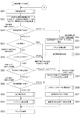
(1)電源投入時に電源投入処理(図6A〜図16)を実行可能に構成され、遊技動作を中心的に制御する制御手段(主制御部20)と、
遊技機本体に開閉可能に配置された前扉の開放状態を検出可能な扉開放検出手段(扉開放センサ61)と、
設定スイッチ(設定キースイッチ94)と、
RAMクリアスイッチ(98)と、を備え、
遊技者に対する有利度が異なる複数種類の設定値のうちからいずれかの設定値に設定可能に構成された遊技機であって、
前記電源投入処理は、
前記設定値を変更可能な設定変更状態に制御する設定変更制御処理(図6AのS023、図10)と、
現在の設定値を確認可能な設定確認状態に制御する設定確認制御処理(図6BのS027、図13)と、
バックアップから復帰させるためのバックアップ復帰処理(図6BのS028、図14)と、
前記設定スイッチのオン/オフ状態を示す設定スイッチ信号、前記扉開放検出手段の扉開放/扉閉鎖状態を示す扉開放信号、および前記RAMクリアスイッチのオン/オフ状態を示すRAMクリアスイッチ信号を取得可能に構成された信号取得処理(図7のS067)と、
前記信号取得処理により取得された信号の状態を判定する判定処理(図6AのS014、図6BのS025、S026)と、を含み、
前記判定処理は、
前記設定スイッチ信号の状態、前記扉開放信号の状態、および前記RAMクリアスイッチ信号の状態に基づき、前記設定変更制御処理に移行するか否かを判定する設定変更移行判定処理(図6AのS014)と、
前記設定スイッチ信号の状態、前記扉開放信号の状態、および前記RAMクリアスイッチ信号の状態に基づき、前記設定確認制御処理に移行するか否かを判定する設定確認移行判定処理(図6BのS026)と、を含み、
前記設定確認移行判定処理により前記設定確認制御処理に移行しないと判定された場合、前記バックアップ復帰処理に移行するように構成した(図6BのS026:≠W(1,1,0))、
ことを特徴とする遊技機。
(2)前記設定変更移行判定処理は、
少なくとも前記扉開放信号の状態が扉閉鎖状態である場合、前記設定変更制御処理に移行しないと判定する(図30、図6AのS014)、
ことを特徴とする上記(1)に記載の遊技機。
(3)前記設定確認移行判定処理は、
少なくとも前記扉開放信号の状態が扉閉鎖状態である場合、前記設定確認制御処理に移行しないと判定する(図30、図6BのS026)、
ことを特徴とする上記(1)または(2)に記載の遊技機。
The above object of the present invention is achieved by the following means. The corresponding elements in the embodiments are shown in parentheses, but the present invention is not limited thereto.
(1) A control means (main control unit 20) that is configured to be able to execute the power-on process (FIGS. 6A to 16) when the power is turned on and that mainly controls the game operation.
Door open detection means (door open sensor 61) that can detect the open state of the front door that is openable and closable on the game machine body, and
Setting switch (setting key switch 94) and
Equipped with a RAM clear switch (98)
A gaming machine configured so that it can be set to one of a plurality of types of setting values having different advantages to the player.
The power-on process is
Setting change control processing (S023 in FIG. 6A, FIG. 10) for controlling the set value to a changeable setting change state, and
Setting confirmation control processing (S027 in FIG. 6B, FIG. 13) that controls the current setting value to a confirmable setting confirmation state, and
Backup restoration processing for restoring from backup (S028 in FIG. 6B, FIG. 14) and
Acquires a setting switch signal indicating an on / off state of the setting switch, a door opening signal indicating a door opening / closing state of the door opening detecting means, and a RAM clear switch signal indicating an on / off state of the RAM clear switch. Possible signal acquisition processing (S067 in FIG. 7) and
A determination process (S014 in FIG. 6A, S025, S026 in FIG. 6B) for determining the state of the signal acquired by the signal acquisition process is included.
The determination process is
Setting change transition determination process for determining whether or not to shift to the setting change control process based on the state of the setting switch signal, the state of the door open signal, and the state of the RAM clear switch signal (S014 of FIG. 6A). When,
Setting confirmation transition determination processing for determining whether or not to shift to the setting confirmation control processing based on the state of the setting switch signal, the state of the door opening signal, and the state of the RAM clear switch signal (S026 in FIG. 6B). And, including
When it is determined by the setting confirmation migration determination process that the process does not shift to the setting confirmation control process, the process is configured to shift to the backup restoration process (S026: ≠ W (1,1,0) in FIG. 6B).
A gaming machine characterized by that.
(2) The setting change transition determination process is performed.
If at least the state of the door open signal is the door closed state, it is determined that the process does not shift to the setting change control process (S014 in FIGS. 30 and 6A).
The gaming machine according to (1) above.
(3) The setting confirmation transition determination process is performed.
If at least the state of the door open signal is the door closed state, it is determined that the process does not shift to the setting confirmation control process (S026 in FIGS. 30 and 6B).
The gaming machine according to (1) or (2) above.
本発明によれば、設定機能に対する不正行為を効果的に防止することができる。 According to the present invention, fraudulent acts on the setting function can be effectively prevented.
以下、図面を参照しながら、本発明に係る遊技機の好ましい実施形態について詳細に説明する。なお、以下に述べる実施形態では、本発明に係る遊技機として、パチンコ遊技機を例にとって説明する。 Hereinafter, preferred embodiments of the gaming machine according to the present invention will be described in detail with reference to the drawings. In the embodiment described below, a pachinko gaming machine will be described as an example of the gaming machine according to the present invention.
[第1の実施形態]
<1.構成の概要:図1および図2>
図1および図2を参照して、本発明の一実施形態に係るパチンコ遊技機の構成の概要を説明する。図1は本発明の一実施形態に係るパチンコ遊技機の外観を示す正面側の斜視図を、図2は遊技盤の正面側を示した図である。
[First Embodiment]
<1. Outline of configuration: Fig. 1 and Fig. 2>
An outline of the configuration of the pachinko gaming machine according to the embodiment of the present invention will be described with reference to FIGS. 1 and 2. FIG. 1 is a front perspective view showing the appearance of the pachinko gaming machine according to the embodiment of the present invention, and FIG. 2 is a view showing the front side of the gaming board.
図1に示すパチンコ遊技機1(以下「遊技機1」と略す)は、木製の外枠4の前面に額縁状の前枠2を開閉可能に取り付け、前枠2の裏面に取り付けた遊技盤収納フレーム(図示せず)内に遊技盤3(図2参照)を装着し、この遊技盤3の表面に形成した遊技領域3aを前枠2の開口部に臨ませた構成を有する。この遊技領域3aの前側には、透明ガラスを支持したガラス扉6が設けられている。また遊技盤3の背面側には、遊技動作を制御するための各種制御基板(図3参照)が配設されている。
The
ガラス扉6の前側には扉ロック解除用のキーシリンダ(図示せず)が設けられており、このキーシリンダにキーを差し込んで一方側に操作すれば前枠2に対するガラス扉6のロック状態を、他方側に操作すれば外枠4に対する前枠2のロック状態をそれぞれ解除して前側に開放できるようになっている。
A key cylinder (not shown) for unlocking the door is provided on the front side of the
ガラス扉6の下側には、ヒンジ(図示せず)により前枠2に開閉自在に枢支された前面操作パネル7が配置されている。前面操作パネル7には、上受け皿ユニット8が設けられ、この上受け皿ユニット8には、排出された遊技球を貯留する上受け皿9が形成されている。
Below the
また上受け皿ユニット8には、上受け皿9に貯留された遊技球を遊技機1の下方に抜くための球抜きボタン14と、遊技球貸出装置(図示せず)に対して遊技球の払い出しを要求するための球貸しボタン11と、遊技球貸出装置に挿入した有価価値媒体の返却を要求するためのカード返却ボタン12とが設けられている。
Further, the
また上受け皿ユニット8には、遊技者が操作可能に構成された、押しボタン式の演出ボタン13(第1の操作手段)と、上下左右方向に操作可能な十字形の方向キー75(第2の操作手段)とが設けられている。演出ボタン13または方向キー75(上ボタン75a、右ボタン75b、下ボタン75c、左ボタン75d)は、いわゆる「遊技者参加型演出」等における所定の操作受付有効期間中に操作入力の受付が有効化され、この期間中に所定の操作(たとえば、1回押し、長押し、連打等)がなされると、その操作の前後で演出に変化をもたらすことができるようになっている。また、これらの操作手段は、後述の「客待ち待機演出中(デモ画面中)」における遊技に関する遊技設定画面(音量設定、光量設定、演出モード設定等が可能なメニュー画面)において、遊技者が好みの遊技設定を行う際にも利用される。なお、枠演出ボタン13は、その内部に内蔵ランプ(ボタンLED13b)が形成されており、操作受付有効期間になると、ボタンLED13bが所定色で点灯され、操作有効期間中であることが報知されるようになっている。
Further, the
また前面操作パネル7の右端部側には、発射装置32(図3参照)を作動させるための発射操作ハンドル15が設けられている。
Further, a launch operation handle 15 for operating the launch device 32 (see FIG. 3) is provided on the right end side of the
また前枠2の上部の両側と発射操作ハンドル15の上側とには、音響により音演出効果(効果音)を発揮するスピーカ46が設けられている。また、遊技機の適所、たとえば、ガラス扉6の前枠周縁に周方向や後述のセンター飾り体48の内部に、光の装飾により光演出効果を発揮する装飾ランプ45(フルカラーLED(光演出用LED))が複数設けられている。
Further,
(遊技盤:図2)
次に図2を参照して、遊技盤3の構成について説明する。遊技盤3には、図示のように、発射された遊技球を案内する球誘導レール5が盤面区画部材として環状に装着されており、この球誘導レール5に取り囲まれた略円形状の領域が遊技領域3a、四隅は非遊技領域となっている。
(Game board: Fig. 2)
Next, the configuration of the
この遊技領域3aの略中央部には、液晶表示装置(LCD)36が設けられている。この液晶表示装置36は、後述する演出制御部24の制御の下、たとえば3つ(左、中、右)の表示エリア(図柄変動表示領域)において、独立して数字やキャラクタや記号などによる複数種類の装飾図柄(たとえば、左図柄(左表示エリア対応)、中図柄(中表示エリア対応)、右図柄(右表示エリア対応))の変動表示動作(変動表示および停止表示)を含む、種々の演出を画像により表示する。
A liquid crystal display (LCD) 36 is provided in a substantially central portion of the
また遊技領域3a内には、液晶表示装置36の表示面の周りを遠巻きに囲繞する形でセンター飾り体48(流路振分手段)が設けられている。センター飾り体48は、周囲の遊技球から液晶表示装置36の表示面を保護するとともに、遊技盤3の前面側に沿って設けられ、遊技盤3に固定される前面装着板48aと、センター飾り体48の外周囲を形成し液晶表示装置36の表示画面を取り囲む鎧枠部48bとを一体に備えている。このセンター飾り体48の上面と球誘導レール5との間には遊技球が通過可能な遊動領域が形成され、センター飾り体48の右側へも遊技球が案内されるようになっている。発射装置32により遊技領域3aの上部側に打ち込まれた遊技球は、遊技球の打ち出しの強さまたはストローク長によって、鎧枠部48bの上部側で左右に振り分けられ、センター飾り体48の左側の左流下経路3bと右側の右流下経路3cとのいずれかを流下する。
Further, in the
また遊技盤3の右上縁付近(右上隅)の非遊技領域は各種機能表示部となっており、7セグメント表示器(ドット付)を上始動口34(第1の特別図柄用)と、下始動口35(第2の特別図柄用)に対応させて横に並べて構成される特別図柄表示装置38a(第1の特別図柄表示手段)と特別図柄表示装置38b(第2の特別図柄表示手段)とが設けられている。特別図柄表示装置38a、38bでは、「特別図柄」の変動表示動作(変動開始および変動停止を一セットする変動表示動作)による‘特別図柄変動表示ゲーム’が実行されるようになっている。そして上記の液晶表示装置36では、この特別図柄表示装置38a、38bによる特別図柄の変動表示と時間的に同調して、画像による装飾図柄を変動表示するもので、種々の予告演出(演出画像)とともに‘装飾図柄変動表示ゲーム’が実行されるようになっている。なお、特別図柄変動表示ゲーム、装飾図柄変動表示ゲームについての詳細は追って説明する。
In addition, the non-game area near the upper right edge (upper right corner) of the
また各種機能表示部には、特別図柄表示装置38a、38bの隣に、7セグメント表示器(ドット付)からなる複合表示装置(保留複合表示用LED表示器)38cが配設されている。複合と称したのは、特別図柄1、特別図柄2、普通図柄の各作動保留球数の表示、変動時間短縮機能作動中(時短中)と高確率状態中(高確中)の状態報知という、5つの表示機能を有する保留・時短・高確複合表示装置(以下「複合表示装置」と称する)であるからである。
Further, in the various function display units, a composite display device (LED display for holding composite display) 38c composed of a 7-segment display (with dots) is arranged next to the special
また各種機能表示部には、複合表示装置38cの隣りに、複数個(この実施形態では2個)のLEDを配置してなる普通図柄表示装置39a(普通図柄表示手段)が設けられている。この普通図柄表示装置39aでは、2個のLEDにより表現される普通図柄の変動表示動作により普通図柄変動表示ゲームが実行されるようになっている。たとえば、変動表示動作として、LEDによる普通図柄がシーソー的に交互に点灯と消灯を繰り返し、いずれかの側が点灯した状態で停止することで、普通図柄変動表示ゲームの当否が判明するようになっている。また、この普通図柄表示装置39aに隣接して右打ち表示装置39bが設けられている。この右打ち表示装置39bは、LEDの点灯・消灯状態の組合せにより、遊技球が右流下経路3cを通過するように狙いを定める「右打ち」が有利であるのか、遊技球が左流下経路3bを通過するように狙いを定める「左打ち」が有利であるのかを報知する。LEDが点灯した状態であれば、右打ち有利であることが報知される。また、右打ち表示装置39bに隣接して2個のLED(ラウンド表示LED)を配置してなるラウンド数表示装置39cが設けられている。このラウンド数表示装置39cは、2つのLEDの点灯(赤色、青色)・消灯状態の組合せにより、大当りに係る規定ラウンド数(最大ラウンド数)を報知する。
Further, the various function display units are provided with a normal
センター飾り体48の下方には、上始動口34(第1の特別図柄始動口:第1の始動手段)と、下始動口35(第2の特別図柄始動口:第2の始動手段)を備える普通変動入賞装置41とが上下に設けられ、それぞれの内部には、遊技球の通過を検出する検出センサ34a、35a(上始動口センサ34a、下始動口センサ35a:図3参照)が形成されている。
Below the
第1の特別図柄始動口である上始動口34は、特別図柄表示装置38a(第1の特別図柄表示装置)における第1の特別図柄(以下「特別図柄1」と称し、場合により「特図1」と略す)の変動表示動作の始動条件に係る入賞口であり、始動口を開放または拡大可能にする「始動口開閉手段」を有しない入賞率固定型の入賞装置として構成されている。本実施形態では、遊技領域3a内の遊技球落下方向変換部材(たとえば、遊技くぎ(図示せず)、風車44、センター飾り体48など)の作用により、上始動口34へは、左流下経路3bを流下してきた遊技球については入球(入賞)容易な構成であるのに対し、右流下経路3cを流下してきた遊技球については入球困難または入球不可能な構成となっている。
The
普通変動入賞装置41は、始動口開閉手段により始動口の遊技球の入賞率を変動可能な入賞率変動型の入賞装置として構成されている。本実施形態では、始動口開閉手段として左右一対の可動翼片(可動部材)47を備え、この可動翼片47が開閉動作を行うことで、第2の特別図柄始動口である下始動口35を開放または拡大可能となっている。
The ordinary variable winning
普通変動入賞装置41の下始動口35は、特別図柄表示装置38b(第2の特別図柄表示装置)における第2の特別図柄(以下「特別図柄2」と称し、場合により「特図2」と略す)の変動表示動作の始動条件に係る入賞口であり、この下始動口35の入賞領域は、可動翼片47の作動状態(作動または非作動)に応じて、入賞を容易とする開状態(入賞容易状態)と、その開状態よりも入賞を困難にし、または入賞を不可能にする閉状態(入賞困難状態)とに変換される。本実施形態では、可動翼片47が非作動の場合、下始動口35への入賞が不可能とする閉状態(入賞不可能状態)を保持している。
The
また普通変動入賞装置41の両側には、一般入賞口43が左側に3つ、右側に1つ、計4つ配設されており、それぞれの内部には、遊技球の通過を検出する一般入賞口センサ43a(図3参照)が形成されている。
Further, on both sides of the normal
また普通変動入賞装置41の右斜め上方、つまり右流下経路3cの中間部より上部側には、遊技球が通過可能な通過ゲート(特定通過領域)からなる普通図柄始動口37が設けられている。この普通図柄始動口37は、普通図柄表示装置39aにおける普通図柄の変動表示動作に係る入賞口であり、その内部には、通過する遊技球を検出する普通図柄始動口センサ37a(図3参照)が形成されている。
Further, an ordinary symbol start
右流下経路3c内の普通図柄始動口37から普通変動入賞装置41へかけての経路途中には、突没式の開放扉52bにより大入賞口50を開放または拡大可能に構成された特別変動入賞装置52(特別電動役物)が設けられており、その内部には大入賞口50に入球した遊技球を検出する大入賞口センサ52a(図3参照)が形成されている。
In the middle of the route from the normal
大入賞口50の周囲は、遊技盤3の表面から膨出した膨出部(装飾部材)55となっており、この膨出部55の上辺55aが右流下経路3cの下流案内部を形作っている。そして開放扉52bにより大入賞口50が閉鎖状態(大入賞口閉状態)であれば、この膨出部55の上辺55aと連続する面を形成することによって、右流下経路3cの下流案内部(上辺55a)の一部を形作るようになっている。また右流下経路3cの下流域には、膨出部55の上辺55aの上方の領域、正確には大入賞口50の上方の遊技領域において、遊技球の流下方向にほぼ平行に流路修正板51dが突設されており、流下する遊技球を大入賞口50の方向に寄せる働きをするようになっている。
The circumference of the large winning
大入賞口50への遊技球の入球過程は次のようになる。センター飾り体48の上面と球誘導レール5との間の遊動領域を通過した遊技球は、遊技盤3より突出していて遊技球のガイドとして機能する膨出部55の頂面(上辺)55a上に沿って流下して来る。そして、その遊技球が遊技盤3面から突出している流路修正板51dの右端に接触し、これにより、当該遊技球の流下方向は大入賞口50の方向(下方向)に修正される。このとき、突没式の開放扉52bにより大入賞口50が蓋をされている状態(大入賞口閉状態)であれば、この上を遊技球が転動して、さらに図示しない所定配列の遊技くぎにより、チューリップ式の普通変動入賞装置41(下始動口35)の方向に導かれる。このとき、下始動口35が入賞可能状態(始動口開状態)であれば、下始動口35に遊技球が入賞しうるが、開放扉52bが遊技盤面内に後退していて大入賞口50が開いている状態(大入賞口開状態)であれば、遊技球が大入賞口50内に導かれるようになっている。
The process of entering the game ball into the
本実施形態のパチンコ遊技機1では、遊技者が特別変動入賞装置52側に発射位置を狙い定めた場合(遊技球が右流下経路3cを通過するように狙いを定めた場合)、上始動口34側には遊技球が誘導され難い、または誘導されない構成となっている。したがって「大入賞口閉状態」であれば、普通変動入賞装置41の可動翼片47が作動しない限り、各始動口34、35への入賞が困難または不可能とされる。しかし可動翼片47は、後述の電サポ有り状態を伴う遊技状態になると、少なくとも通常状態よりも有利な開閉パターンで動作する。したがって、この電サポ有り状態の場合には、遊技球が左流下経路3bを通過するように狙いを定める「左打ち」ではなく、遊技球が右流下経路3cを通過するように狙いを定める「右打ち」が有利とされる。すなわち、「左打ち」か「右打ち」のいずれの打ち方をすれば遊技者にとり有利な状況となるかについては、遊技状態に応じて変化し、電サポ無し状態下(たとえば、通常状態や後述の潜確状態)では「左打ち」が、電サポ有り状態下(たとえば、時短状態や確変状態)では「右打ち」が有利とされる。
In the
上記各入賞手段については、遊技性に応じて、その個数、形状、形成位置などについては適宜変更することができる。また、各入賞手段が左流下経路3bおよび/または右流下経路3cのいずれを流下する遊技球が入賞可能であるかについても遊技性に応じて適宜変更することができる。
The number, shape, formation position, etc. of each of the above-mentioned winning means can be appropriately changed according to the playability. Further, which of the
本実施形態のパチンコ遊技機1においては、遊技領域3aに設けられた各種入賞口のうち各入賞口別に約束づけられた入賞球1個当りの賞球数(たとえば、上始動口34は3個、下始動口35は1個、大入賞口50は15個、一般入賞口43は6個、普通図柄始動口37は0個(賞球なし))が遊技球払出装置19から払い出されるようになっている。上記の各入賞口に入賞しなかった遊技球は、アウト口49を介して遊技領域3aから排出される。ここで「入賞」とは、入賞口がその内部に遊技球を取り込んだり、または入賞口が遊技球を内部に取り込む構造ではなく、通過型のゲートからなる入賞口(たとえば、普通図柄始動口37)である場合は、そのゲートを遊技球が通過したりすることをいい、実際には入賞口ごとに形成された各入賞検出スイッチにより遊技球が検出された場合、その入賞口に「入賞」が発生したものとして扱われる。この入賞に係る遊技球を「入賞球」とも称する。なお、入賞口に遊技球が入球すれば、その遊技球は入賞検出スイッチにより検出されることとなるため、本明細書中では特に断りのない限り、入賞検出スイッチに遊技球が検出されたか否かによらず、入賞口に遊技球が入球した場合を含めて「入賞」と称する場合がある。
In the
<可動体役物>
また遊技盤の領域内には遊技球の流下を妨害しない位置に複数の可動体役物が配設されている。本例ではセンター飾り体48内の右上側、つまり右流下経路3cを通る遊技球の流下を妨害しない位置に第1の可動体役物(時計型役物)80が配設され、その右斜め下側に第2の可動体役物(花型役物)90が配設されている。第1の可動体役物である時計型役物80は、ローマ文字「I」から「XII」の数字が付されて12の数字セクターに区画された数字表示部からなる時計盤部81と、この時計盤部81上を回動し、必要に応じて時分を示すことができる短針および長針からなる時計針82とを有し、全体として時計型役物80として構成されている。この時計型役物80は、時計針82がぐるぐる高速で回り、時計盤部81の数字セクターが所定の「色と個数」で発色し、遊技者に対し当りへの期待度を示す働きをする。また第2の可動体役物である花型役物90は、花心A1の周りに複数枚の花弁からなる花冠A2を配し、花心A1および花冠A2を上下方向(落下移動)または左右方向に移動可能(突出移動)に構成した第1可動体91と、その花冠A2の外側周囲に位置する萼B1を茎部B2の先端に取り付け、萼B1および茎部B2を上下方向(落下移動)可能に構成した第2可動体92とから構成される。第1可動体91と第2可動体92は、図示のように、液晶画面の片側近く(右側方)の実線位置を初期位置とし、両者が合体した状態で配置されている。この実施形態の場合、第1可動体91と第2可動体92は互いに独立に動作可能であり、また第1可動体91と第2可動体92とが合体しながら上下方向にも動作可能である。可動体役物は演出手段として機能し、その動作態様により、当りへの期待度を示唆するなどの可動体演出を実現する。
<Movable body accessory>
Further, in the area of the game board, a plurality of movable body accessories are arranged at positions that do not interfere with the flow of the game ball. In this example, the first movable body accessory (clock-shaped accessory) 80 is arranged on the upper right side of the
<2.制御装置:図3>
次に図3を参照して、本実施形態に係る遊技機1の遊技動作制御を司る制御装置について説明する。図3は、その制御装置の概要を示す制御ブロック図である。
<2. Control device: Fig. 3>
Next, with reference to FIG. 3, the control device that controls the game operation control of the
本実施形態に係る遊技機1の制御装置は、遊技動作全般に係る制御(遊技動作制御)を統括的に司る主制御基板(主制御手段)20(以下「主制御部20」と称する)と、主制御部20から演出制御コマンドを受けて、演出手段による演出の実行制御(現出制御)を統括的に司る演出制御基板(演出制御手段)24(以下「演出制御部24」と称する)と、遊技球払出装置19による賞球の払い出し制御を行う払出制御基板(払出制御手段)29と、外部電源(図示せず)から遊技機の各基板に対して必要な電源(バックアップ電源を含む)を生成し供給する電源基板(電源制御手段(図示せず))と、を中心に構成される。また演出制御部24には、画像表示装置としての液晶表示装置36が接続されている。なお、図3において電源供給ルートは省略してある。
The control device of the
(2−1.主制御部20)
主制御部20は、CPU201(主制御CPU)を内蔵したマイクロプロセッサを搭載するとともに、遊技動作制御手順を記述した制御プログラムの他、遊技動作制御に必要な種々のデータを格納するROM202(主制御ROM)と、ワークエリアやバッファメモリとして機能するRAM203(主制御RAM)とを搭載し、全体としてマイクロコンピュータ(Z80システム相当品)を構成している。
(2-1. Main control unit 20)
The
また図示はしていないが、主制御部20は、Z80システムに周期的割込みや一定周期のパルス出力作成機能(ビットレートジェネレータ)や時間計測の機能を付与するCTC、CPUに割込み信号を付与するタイマ割込み等の割込許可/割込禁止機能を発揮する割込みコントローラ回路、電源投入時や遮断時や電源異常などを検知してシステムリセット信号を出力してCPUをリセット可能なリセット回路、制御プログラムの動作異常を監視するウォッチドッグタイマ(WDT)回路、あらかじめ設定したアドレス範囲内でプログラムが正しく実行されているか否かを監視する指定エリア外走行禁止(IAT)回路、ハードウェア的に一定範囲の乱数を生成するためのカウンタ回路なども備えている。なお、少なくとも主制御部(払出制御基板)20と払出制御基板29とは、電源基板から受ける電圧降下信号を受けることによって、電源遮断に先立ち、必要なバックアップ処理の実行を開始し、電源遮断前の遊技動作を電源復帰後に再開できるようになっている(バックアップ機能)。この遊技機1では少なくとも数日は、各RAMの記憶内容が保持することが可能となっている。
Although not shown, the
上記カウンタ回路は、乱数を生成する乱数生成回路と、その乱数生成回路から所定のタイミングで乱数値をサンプリングするサンプリング回路とを含んで構成され、全体として16ビットカウンタとして働く。CPU201は、処理状態に応じて上記サンプリング回路に指示を送ることで、上記乱数生成回路が示している数値を内部抽選用乱数値(大当り判定用乱数(乱数の大きさ:65536))として取得し、その乱数値を大当り抽選に利用する。なお、内部抽選用乱数は、当り狙い打ち等のゴト行為を防ぐために、適宜なソフトウェア処理で生成しているソフト乱数値と、ハード乱数値とを加算したものを取得している。
The counter circuit includes a random number generation circuit that generates a random number and a sampling circuit that samples a random number value at a predetermined timing from the random number generation circuit, and acts as a 16-bit counter as a whole. By sending an instruction to the sampling circuit according to the processing state, the
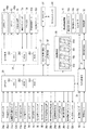
<メモリアドレスマップ:図29>
ここで本発明の理解を容易なものとするために、図29に、主制御部20が用いるメモリ空間(RAM203、ROM202)に関するアドレスマップの概要を示す。図29に示すメモリ空間は、16ビットアドレスでアクセスするメモリ空間と、8ビットアドレスでアクセスするI/O空間の2つの空間を中心に構成される。
<Memory address map: Fig. 29>
Here, in order to facilitate the understanding of the present invention, FIG. 29 shows an outline of an address map relating to the memory space (
主制御部20が用いるメモリ空間は、図示の通り、メモリアドレスマップとして、0000H番地〜FFFFH番地まで備えている。具体的には、0000H番地〜01FFH番地までがRAM203のメモリ空間(512バイト)、0200H番地〜0FFFH番地までがアクセスが禁止される未使用領域(以下、「アクセス禁止領域」と称する)、1000H番地〜1072H番地が内部機能レジスタ(主制御部20に搭載されている各機能を制御するためのレジスタ群)のメモリ空間、1073H番地〜7FFFH番地がアクセス禁止領域、8000H番地〜A7FFH番地がROM202のメモリ空間、A800H番地〜FFFFH番地がアクセス禁止領域に割り当てられている。
As shown in the figure, the memory space used by the
ROM202の領域は、図示のように、8000H番地〜A7FFH番地のメモリ空間(10240バイト)のうち、8000H番地〜A6FFH番地までが一連の遊技制御手順を記述した「プログラム/データ領域」、A700H番地〜A77FH番地までが‘ROMコメント格納領域’、A780H番地〜A79FH番地が「CALLV命令ベクタ領域」、A7A0H番地〜A7A7H番地までが「割込み処理ベクタ領域」、A7A8H番地〜A7FFHが「HWパラメータ領域」に割り当てられている。
As shown in the figure, the area of
ROM202の「プログラム/データ領域」は、図柄変動表示ゲームや当り遊技など、通常の遊技進行に関する遊技動作処理を実行するための「遊技制御プログラム(領域内プログラム)」や、後述のベース表示など、当該遊技進行に直接関連しない‘性能情報表示’に関する情報表示処理(ベース表示処理)を実行するための「情報表示制御プログラム(領域外プログラム)」や、プログラムに関する各種の固定データなどを格納する領域である。CPU201は、リセット後、8000H番地からプログラムの実行を開始するようになっている。なお、RAM203には、図示のように、領域内プログラムと領域外プログラムにそれぞれ対応するワーク領域(0000H番地〜00FFH番地の領域内RAM領域と、0100H番地〜01FFH番地の領域外RAM領域)が設けられている。
The "program / data area" of the
また「ROMコメント領域」は、プログラムタイトル、メーカー名、製品バージョンなどの任意のデータが設定可能な領域である。また「CALLV命令ベクタ領域」は、後述のCALLV命令のサブルーチンの上位アドレスを設定する領域であり(CALLV命令ベクタテーブル)、「割込み処理ベクタ領域」は、タイマ割込処理(メイン)の先頭アドレスを設定する領域(割込み処理ベクタテーブル)である。また「HWパラメータ領域」は、CPU内部機能をハードウェア的に設定するためのパラメータの設定可能領域である。HWパラメータ領域に設定されるパラメータには、たとえば、定期リセット設定、システムクロック設定、INT/NMI設定、プログラム/データ領域で使用するプログラムエンドアドレス(HPRGEND)、アクセス禁止領域のスタートアドレス(HRAMSTAT)およびエンドアドレス(HRAMEND)、セキュリティコード、メーカーコード、製品コードなどに関するデータが含まれる。なお、プログラムエンドアドレス(HPRGEND)で設定されたアドレスの次のアドレス以降のプログラム/データ領域(HPRGEND+1〜A6FFH番地の領域(プログラムやデータが格納されていない領域))へのアクセス、ROMコメント領域(A700H〜A77FH番地)へのアクセス、スタートアドレス(HRAMSTAT)からエンドアドレス(HRAMEND)の間の領域(アクセス禁止領域)へのアクセス、ROM領域への書き込み動作などの事象を検出した場合には、不正アクセスが発生したとみなして、CPUコアだけをリセットするイリーガルリセットが発生するようになっている。イリーガルリセットが発生した場合、エラー状態に制御され、遊技の進行が停止されるとともに、新たな設定値が設定されるまで(後述の設定変更管理処理(図6AのステップS023)が実行されるまで)、そのエラーが解除されないようになっている。 The "ROM comment area" is an area in which arbitrary data such as a program title, a manufacturer name, and a product version can be set. The "CALLV instruction vector area" is an area for setting the upper address of the subroutine of the CALLV instruction described later (CALLV instruction vector table), and the "interrupt processing vector area" is the start address of the timer interrupt processing (main). Area to set (interrupt processing vector table). The "HW parameter area" is a parameter settable area for setting CPU internal functions in terms of hardware. The parameters set in the HW parameter area include, for example, a periodic reset setting, a system clock setting, an INT / NMI setting, a program end address (HPRGEND) used in the program / data area, a start address (HRAMSTAT) in the access prohibited area, and the like. Data related to the end address (HRAMEND), security code, manufacturer code, product code, etc. are included. Access to the program / data area (HPRGEND + 1 to A6FFH area (area where programs and data are not stored)) after the address set by the program end address (HPRGEND), ROM comment area (ROM comment area) Illegal when an event such as access to (A700H to A77FH), access to the area (access prohibited area) between the start address (HRAMSTAT) and the end address (HRAMEND), and write operation to the ROM area is detected. It is assumed that an access has occurred, and an illegal reset that resets only the CPU core occurs. When an illegal reset occurs, it is controlled to an error state, the progress of the game is stopped, and until a new setting value is set (until the setting change management process described later (step S023 in FIG. 6A) is executed). ), The error is not cleared.
図3の説明に戻る。主制御部20には、上始動口34への入賞を検出する上始動口センサ34aと、下始動口35への入賞を検出する下始動口センサ35aと、普通図柄始動口37への遊技球の通過を検出する普通図柄始動口センサ37aと、大入賞口50への入賞を検出する大入賞口センサ52aと、一般入賞口43への入賞を検出する一般入賞口センサ43aと、アウト口49および各入賞口を通じて遊技機から排出される遊技球(いわゆる、アウト球)を検出するOUT監視スイッチ49aとが接続され、主制御部20はこれらからの検出信号を受信可能となっている。主制御部20は、各センサからの検出信号に基づき、いずれの入賞口に遊技球が入賞(入球)したのかを把握する。
Returning to the description of FIG. The
また主制御部20には、RAM203の所定領域を初期化するためのRAMクリアスイッチ98(たとえば、押しボタン式スイッチ)と、図示はしていないがパチンコ遊技機1に対する不正行為(電波エラー、磁気エラー、振動エラー等)を検出するための不正検出センサ(振動センサ、電波センサ、磁気センサ等)とが接続され、主制御部20はこれらからの検出信号を受信可能となっている。
Further, the
また主制御部20には、下始動口35の可動翼片47を開閉制御するための普通電動役物ソレノイド41cと、大入賞口50の開放扉52bを開閉制御するための大入賞口ソレノイド52cとが接続され、主制御部20はこれらを制御するための制御信号を送信可能となっている。
Further, the
また主制御部20には、特別図柄表示装置38aと、特別図柄表示装置38bとが接続され、主制御部20は、特別図柄1、2を表示制御するための制御信号を送信可能となっている。また主制御部20には、普通図柄表示装置39aが接続され、普通図柄を表示制御するための制御信号を送信可能となっている。
Further, the special
また主制御部20には、複合表示装置38cと、右打ち表示装置39bと、ラウンド数表示装置39cとが接続され、主制御部20は、これらに表示される各種情報を表示制御するための制御信号を送信可能となっている。
Further, the
また主制御部20には、枠用外部端子基板21が接続され、主制御部20は、この枠用外部端子基板21から所定の遊技情報(たとえば、当り遊技開始情報、始動口への入賞情報(特別図柄の変動開始情報)、賞球数情報、セキュリティ情報(たとえば、振動センサエラー、電波センサエラー、磁気センサエラー、RAMクリア、設定変更等の発生情報)を含む信号(外端信号)を遊技機の外部に出力可能となっている。枠用外部端子基板21は、遊技機外部に設けられた、いわゆるデータカウンタDTや、ホールコンピュータHCに接続可能に構成されており、枠用外部端子基板21から出力される信号(外端信号)が、データカウンタDTや、ホールコンピュータHCに送られる。なお、データカウンタDTは、接続されている遊技機に関する特定の遊技情報を報知する遊技情報報知装置であり、通常、遊技機の上部に設置される。また、ホールコンピュータHCは、枠用外部端子基板21から出力される外端信号に基づき、遊技機の遊技情報を監視・収集し、パチンコホールに設置された遊技機の稼働状況等を統括的に管理する遊技店専用の管理コンピュータである。
Further, a frame external
また主制御部20は、保安電子通信技術協会(保通協)で実施される型式試験(遊技機の認定及び型式の検定等に関する規則に基づく遊技機の型式に関する検定に係る試験)に対応して、遊技動作をリアルタイムに特定する型式試験信号を枠用外部端子基板21から出力可能となっている。なお、型式試験に適合した遊技機をパチンコホールに設置する際には、その適合した制御プログラムの変更は一切認められていない。このため、パチンコホールに設置後も型式試験信号が繰り返し出力処理されることになる(後述の試射試験信号端子管理処理(図25のステップS823)参照)。
In addition, the
また主制御部20には、払出制御基板(払出制御部)29が接続され、この払出制御基板29には、発射装置32を制御する発射制御基板(発射制御部)28と、遊技球の払い出しを行う遊技球払出装置(遊技球払出手段)19とが接続されている。主制御部20は、払出制御基板29に対し、払い出しに関する制御コマンド(賞球数を指定する払出制御コマンド)を送信可能となっている。この払出制御基板29の主な役割は、主制御部20からの払出制御コマンドの受信、払出制御コマンドに基づく遊技球払出装置19の賞球払い出し制御、主制御部20への払出状態信号の送信などである。主制御部20は、払出状態信号に基づき、遊技球払出装置19の機能が正常か否か(玉詰まりや賞球の払い出し不足などが生じたか否か)を監視している。
A payout control board (payout control unit) 29 is connected to the
また主制御部20には、払出制御基板(払出制御部)29が接続され、賞球の払い出しの必要がある場合には、払出制御基板29に対して、払い出しに関する制御コマンド(賞球数を指定する払出制御コマンド)を送信可能となっている。
Further, a payout control board (payout control unit) 29 is connected to the
この払出制御基板29には、発射装置32を制御する発射制御基板(発射制御部)28と、遊技球の払い出しを行う遊技球払出装置(遊技球払出手段)19とが接続されている。この払出制御基板29の主な役割は、主制御部20からの払出制御コマンドの受信、払出制御コマンドに基づく遊技球払出装置19の賞球払い出し制御、主制御部20への状態信号の送信などである。
The
遊技球払出装置19には、遊技球の供給不足を検出する補給切れ検出センサ19aや払い出される遊技球(賞球)を検出する球計数センサ19bが設けられており、払出制御基板29は、これらの各検出信号を受信可能となっている。また遊技球払出装置19には、遊技球を払い出すための球払出機構部(図示せず)を駆動する払出モータ19cが設けられており、払出制御基板29は、払出モータ19cを制御するための制御信号を送信可能となっている。
The game
また払出制御基板29には、上受け皿9が遊技球で満杯状態を検出する満杯検出センサ60(本実施形態では、上受け皿9に貯留される遊技球の貯留状態を検出する検出センサ)と、扉開放センサ61が接続されている。本実施形態に係る扉開放センサ61は、扉開放検出手段として機能し、前枠2および/または前面操作パネル7の開放状態を検出する検出センサであり、たとえば、前枠2が外枠4に対して前側に開放したときにON(開放状態検出)、閉鎖したときにOFF(閉鎖状態検出)となるように構成されている。
Further, the
払出制御基板29は、満杯検出センサ60、扉開放センサ61、補給切れ検出センサ19a、球計数センサ19bからの検出信号に基づいて、主制御部20に対して、各種の状態信号を送信可能となっている。この状態信号には、満杯状態を示す「球詰り信号」、前枠2・前面操作パネル7が開放されていることを示す「扉開放信号」、遊技球払出装置19からの遊技球の供給不足を示す「補給切れ信号」、賞球の払出不足や球計数センサ19bに異常が発生したこと示す「計数エラー信号」、払い出し動作が完了したことを示す「払出完了信号」などが含まれ、様々な状態信号を送信可能な構成となっている。主制御部20は、これら状態信号に基づいて、前枠2・前面操作パネル7の開放状態(扉開放エラー)や、遊技球払出装置19の払出動作が正常か否か(補給切れエラー)や、上受け皿9の満杯状態(球詰りエラー)等を監視する。なお上記では、扉開放センサ61からの検出信号(扉開放信号)は、払出制御基板29を介して主制御部20に入力されると説明したが、払出制御基板29を介さずに主制御部20に直接的に入力される構成でもよい。
The
また払出制御基板29には発射制御基板28が接続され、発射制御基板28に対し発射を許可する発射許可信号ESを送信可能になっている。発射制御基板28は、払出制御基板29からの発射許可信号ESが出力されていることに基づき、発射装置32に設けられた発射ソレノイドへの通電を制御し、発射操作ハンドル15の操作による遊技球の発射動作を実現している。具体的には、払出制御基板29から発射許可信号ESが出力されていること、発射操作ハンドル15に設けられたタッチセンサ(図示せず)により遊技者がハンドルに触れていることを検出されていること、発射操作ハンドル15に設けられた発射停止スイッチ(図示せず)が操作されていないことを条件に、遊技球の発射動作が許容される。したがって、発射許可信号ESが出力されていない場合には、発射操作ハンドル15を操作しても発射動作は実行されず、遊技球が発射されることはない。また、遊技球の打ち出しの強さは、発射操作ハンドル15の操作量に応じて変化可能となっている。なお、払出制御基板29が上記球詰りエラーを検出すると、主制御部20に球詰り信号を送信するとともに発射制御基板28に対する発射許可信号ESの出力を停止し、上受け皿9の満杯状態が解消されるまで打ち出し動作を停止する制御を行うようになっている。
Further, a
また主制御部20には、設定キースイッチ94、設定変更スイッチ95、設定変更完了スイッチ96が接続され、主制御部20はこれらスイッチからの検出信号を受信可能となっている。また主制御部20には、設定表示器97が接続され、主制御部20は、これを表示制御するための制御信号を送信可能となっている。
A setting
設定キースイッチ94は、電源投入時に遊技店の関係者(ホール店員)等が所持する設定鍵を挿入してON/OFF操作することにより、設定値の変更操作が可能な「設定変更許容状態」に切り替えるためのキースイッチである。また、設定変更スイッチ95は、設定変更許容状態において設定値を変更するための設定変更用スイッチである。また、設定変更完了スイッチ96は、選択した設定値を確定させる際に用いる設定確定用スイッチである。設定変更スイッチ95、設定変更完了スイッチ96は、いずれも操作者が操作可能なスイッチ(たとえば、押しボタン式スイッチなど)である。なお、設定キースイッチ94、設定変更スイッチ95、設定変更完了スイッチ96、およびRAMクリアスイッチ98については、不正行為防止の観点から、遊技機内部の適所に形成されており、前枠2を開放しない限り、外部からのON/OFF操作が不可能となっている。
The setting
また設定表示器97は、設定値に関する情報を表示するもので、設定表示手段として機能する。本実施形態の場合、1個の7セグメント表示器から構成されており、主制御部(主制御基板)20上に装着されている。なお、設定表示器97は、主制御基板に限らず、払出制御基板28、発射制御基板29、中継基板(各種表示装置やスイッチ類等と制御基板との接続を中継する中継用基板:図示せず)、または演出制御部(演出制御基板(液晶制御基板を含む))24など、遊技機内部の適所に設けることができる。
Further, the setting
(設定値について)
上記「設定値」とは、段階的に出玉率(所謂、機械割(PAYOUT率))に変化をもたらすものであり、本実施形態では、設定1〜6の6段階の設定値が設けられている。この「設定値」は、少なくとも大当り(後述の条件装置が作動することとなる当り種別)の抽選確率(当選確率)を設定1〜6の段階別(6段階)に規定するもので、設定値が高くなるほど、大当りの抽選確率(大当り当選確率)が高く設定され、遊技者に有利に作用するようになっている。たとえば、低確率時において、設定1で1/410、設定2で1/390、設定3で1/370、設定4で1/350、設定5で1/330、設定6で1/320などである。すなわち、設定値が高くなるほど、大当りに当選し易くなり(機械割が高くなる)、遊技者に有利に作用することになる。このように、設定値とは、主として、機械割に影響する事象を段階別に規定する値であり、大当りなどの特定事象の発生し易さに関連する等級についての値を意味する。斯様な「設定値」は、専ら、パチンコホール(遊技店)の営業戦略に基づき、ホール店員が設定変更スイッチ95を操作して、目的の設定値が決定される。
(About set value)
The above-mentioned "set value" gradually changes the ball output rate (so-called machine discount (PAYOUT rate)), and in the present embodiment, six levels of setting
なお、大当りを複数種類設けている場合には、設定値に応じて、1または複数種類の大当りの当選確率を変化させることができる。たとえば、大当り1〜4という4種類の大当りがある場合、設定値が相対的に高くなるほど、大当り1〜4のすべての当選確率を高くなるように構成してもよいし、一部の大当りである大当り1〜3の当選確率だけを高くなるように構成してもよいし(この場合、大当り4については全設定値で共通の当選確率となる)、特定の大当りのみ(たとえば、大当り1のみ)の当選確率だけを高くなるように構成してもよい(この場合、大当り2〜4については全設定値で共通の当選確率となる)。また、設定値が相対的に高くなるほど、大当り1〜4の合算当選確率を高くなるように構成してもよい。また、条件装置の作動契機とならない小当り種別の当選確率を、前述の大当りのケースと同様に、設定値に応じて変化させることができる。
When a plurality of types of jackpots are provided, the winning probability of one or a plurality of types of jackpots can be changed according to the set value. For example, when there are four types of
(設定値の変更操作について)
本実施形態では、電源投入時に、少なくとも設定キースイッチ94とRAMクリアスイッチ98とがON状態の場合に設定変更許容状態に制御され、それ以外のキー操作等にて、電源を投入した場合には、設定変更禁止状態に制御されるようになっている。この設定変更許容状態中において、設定変更スイッチ95をON操作すると、設定表示器97の現在の表示値が「1→2→3→4→5→6→1→2→3→・・・」のように1〜6の範囲で循環するように切り替え表示される。そして希望する設定値が表示された際に、設定変更完了スイッチ96をON操作すると(設定確定操作)、現在の表示値が今回の設定値として確定され、その設定値データがRAM203の所定領域(設定値格納領域)に格納(記憶)される。以後、確定された設定値の下で遊技が開始されることになる。そして、設定キースイッチ94が現在のON状態からOFF状態に操作すると、設定変更許容状態が終了される。主制御部20は、所定の操作手段の操作に基づいて、遊技者に対する有利度が異なる複数種類の設定値のうちから、いずれかの設定値を選択する設定値選択手段と、設定値選択手段により選択された設定値を設定する設定値設定手段としての機能部を備えている。
(About the operation to change the set value)
In the present embodiment, when the power is turned on, at least when the setting
また主制御部20は、処理状態に応じて、特別図柄変動表示ゲームに関する情報や、エラー情報などの各種遊技処理情報を、演出制御コマンドにより、演出制御部24に対して送信可能となっている。ただし、ゴト行為を防止するために、主制御部20は演出制御部24に対して信号を送信するのみで、演出制御部24からの信号を受信不可能な片方向通信の構成となっている。
Further, the
また主制御部20には、性能表示器99が接続され、主制御部20は、これを表示制御するための制御信号を送信可能となっている。
A
(性能表示器99に表示される遊技結果情報について)
性能表示器99は、所定期間(特定遊技期間)の遊技結果に係る情報(以下「性能情報」と称する)を表示(報知)する情報表示手段として機能し、複数個の7セグメントLEDからなる。本実施形態の性能表示器99は、表示部と回路部がユニット化された7セグメントLED(7セグ表示器99a〜99d)を4個横に並べ、これをたとえば、主制御基板20上に搭載して、4桁の数字を表示可能な表示器を構成する。詳細は後述するが、上記の「性能情報」とは、主に、パチンコホール店や関係各庁が確認・調査等のために利用する情報であり、たとえば、遊技くぎの不正調整やゴト行為などにより出玉性能に異常が生じているか否か等、遊技機本来の出玉性能(設計上の出玉性能)が正当に発揮されているか否かを調査するための情報、換言すれば「遊技実績に関する情報」である。したがって、性能情報自体は、予告演出などとは異なり、遊技者が遊技に興じる際に、その遊技進行自体には直接的に関係の無い情報である。このため性能表示器99は、遊技者に視認可能な箇所に設置するのではなく、遊技機内部の視認し易い箇所に設置される。具体的には、4個の7セグメントLEDで構成される性能表示器99の表示部を遊技機裏面から見やすい場所に、つまりシールや構造物等で隠れて見難くならないように、主制御部(主制御基板)20、払出制御基板28、発射制御基板29、上記中継基板、演出制御部(演出制御基板(液晶制御基板を含む))24などの基板上、あるいは、制御基板を保護する基板ケース上などに搭載される。また4個の7セグメントLEDは横に並べられて4桁の数字を表示可能となっており、各7セグメントLEDには、7セグメント数字の下にデシマルポイントDP(ドット)を有している。
(About the game result information displayed on the performance display 99)
The
上記性能情報には、具体的には、下記のような情報を採用することができる。
(1)特定状態中において入賞により払い出された総払出個数(特定中総賞球数:α個)を、当該特定状態中おける総アウト球数(特定中アウト個数:β個)で除した値(α/β)に基づく情報(特定比率情報)を、性能情報として採用することができる。斯様な特定比率情報は、遊技機が有する出玉性能を評価する指標として有用である。
(1−1)上記「総払出個数」とは、入賞口(上始動口34、下始動口35、一般入賞口43、大入賞口50)に入賞した際に払い出された遊技球(賞球)の合計値である。本実施形態の場合、上始動口34は3個、下始動口35は1個、大入賞口50は15個、一般入賞口43は6個である。総アウト球数とは、発射装置32から遊技領域3aに打ち込まれた遊技球数(OUT監視スイッチ49aにより検出される遊技球数)である。
(1−2)また「特定状態」として、いずれの状態を採用するかについては、取得したい性能情報に応じて適宜定めることができる。本実施形態であれば、通常状態、潜確状態、時短状態、確変状態、大当り遊技中、小当り遊技中などのうち、いずれの状態も採用することができる(各遊技状態についての詳細は後述する)。また、1つの状態だけを計測対象とするのではなく、複数種類の状態を計測対象としてもよい。たとえば、通常状態と潜確状態、通常状態と小当り遊技、当り遊技中を除くすべての遊技状態など、複数種類の状態を計測対象として適宜選択可能である。
(1−3)また、特定状態中の期間として、通常状態等の各遊技状態や当り遊技に着目するのではなく、大当り抽選確率に着目した期間を計測対象としてもよい。たとえば、大当り抽選確率が低確率状態および/または高確率状態の期間を計測対象としてもよい。なお、大当りによる当り遊技(大当り遊技中)は低確率状態に制御され、また小当りによる当り遊技(小当り遊技)中は、その当選時の遊技状態が継続される、つまり小当り遊技中は、小当り当選時の大当り抽選確率状態が継続される。このため、純粋な低確率状態の期間を計測したい場合には、大当り遊技中を除く期間を計測対象とすればよい。また、大当りおよび小当りの双方の当り遊技中を除いた低確率状態および/または高確率状態の期間を計測したい場合には、当り遊技を除く期間を計測対象とすればよい。なお、大当り種別、小当り種別、これらの当り遊技の動作態様などについての詳細は後述する。
(1−4)また「総払出個数」として、1または複数の特定の入賞口を計測対象から除外したものを総払出個数としてもよい(特定入賞口除外総払出個数)。たとえば、各入賞口のうち、大入賞口40、50を計測対象から除外したもの(この場合は、実質的に当り中を計測対象から除外したものが総払出個数となる)を総払出個数としてもよい。
(2)その他、総払出個数、特定入賞口除外総払出個数、総アウト球数のいずれかだけを計測し、その計測結果を性能情報としてもよい。
(3)また、役物比率(役物による総払出個数÷全入賞口の総払出個数)に関する情報を表示してもよい。これにより、総払出遊技球のうち、普通変動入賞装置41(下始動口35)や特別変動入賞装置52(大入賞口50)といった役物による払出の割合を性能情報とすることができる。
Specifically, the following information can be adopted as the performance information.
(1) The total number of payouts paid out by winning in the specific state (total number of prize balls in the specific state: α) is divided by the total number of out balls in the specific state (number of outs in the specific state: β). Information based on the value (α / β) (specific ratio information) can be adopted as performance information. Such specific ratio information is useful as an index for evaluating the ball ejection performance of the gaming machine.
(1-1) The above "total number of payouts" is a game ball (award) paid out when a prize is won in the winning openings (upper starting
(1-2) Further, which state is adopted as the "specific state" can be appropriately determined according to the performance information to be acquired. In the present embodiment, any of the normal state, the latent probability state, the time saving state, the probability variation state, the big hit game, the small hit game, and the like can be adopted (details of each game state will be described later). To do). Further, not only one state may be measured, but a plurality of types of states may be measured. For example, a plurality of types of states such as a normal state and a latent state, a normal state and a small hit game, and all game states except during a hit game can be appropriately selected as measurement targets.
(1-3) Further, as the period in the specific state, the period focusing on the jackpot lottery probability may be the measurement target instead of focusing on each game state such as the normal state or the winning game. For example, a period in which the jackpot lottery probability is in a low probability state and / or in a high probability state may be measured. The hit game by big hit (during the big hit game) is controlled to a low probability state, and during the hit game by small hit (small hit game), the game state at the time of winning is continued, that is, during the small hit game. , The big hit lottery probability state at the time of small hit winning is continued. Therefore, when it is desired to measure the period of the pure low probability state, the period other than during the big hit game may be the measurement target. Further, when it is desired to measure the period of the low probability state and / or the high probability state excluding the hit game of both the big hit and the small hit, the period excluding the hit game may be the measurement target. The details of the big hit type, the small hit type, the operation mode of these hit games, and the like will be described later.
(1-4) Further, as the "total number of payouts", the number of payouts excluding one or more specific winning openings from the measurement target may be used as the total number of payouts (total number of payouts excluded from specific winning openings). For example, among the winning openings, those excluding the large winning
(2) In addition, only any one of the total number of payouts, the total number of payouts excluding specific winning openings, and the total number of out balls may be measured, and the measurement result may be used as performance information.
(3) Further, information on the bonus ratio (total number of payouts by bonus / total number of payouts of all winning openings) may be displayed. As a result, the percentage of the total payout game balls paid out by the accessory such as the normal variable winning device 41 (lower starting port 35) and the special variable winning device 52 (large winning opening 50) can be used as the performance information.
上述した(1)〜(3)の情報のうち、1または複数を性能情報として採用することができる。また、表示対象として複数の性能情報を採用する場合、第1性能情報(後述のベース値)を第1性能表示器に表示し、第2性能情報(たとえば、役物比率情報)を別に設けた第2性能表示器に表示する、といったように性能情報ごとに対応した複数の性能表示器を設けてもよい。また複数の性能情報を1つの性能表示器99で表示する場合、一の性能情報と他の性能情報とを、所定時間間隔で切り替え表示するといった切り替え表示可能な構成としてもよいし、特定のスイッチのON/OFF操作により切り替え表示可能な構成としてもよい。また、性能情報として如何なる情報を採用するかは、適宜定めることができる。
Of the above-mentioned information (1) to (3), one or a plurality of the above-mentioned information can be adopted as the performance information. Further, when a plurality of performance information is adopted as the display target, the first performance information (base value described later) is displayed on the first performance display, and the second performance information (for example, accessory ratio information) is separately provided. A plurality of performance indicators corresponding to each performance information may be provided, such as displaying on the second performance indicator. Further, when displaying a plurality of performance information on one
本実施形態では、通常状態中の総払出個数(通常時払出個数)と、通常状態中の総アウト球数(通常時アウト個数)とをリアルタイムで計測し、通常時払出個数を通常時アウト個数で除した値に百を乗じた値(通常時払出個数÷通常時アウト個数×100で算出される値)を性能情報(ベース値とも称する)として採用し、これを性能表示器99により所定態様にて表示する(表示値は、小数点第1位を四捨五入した値を表示する)。したがって、通常時払出個数、通常時アウト個数、およびベース値の各データが、RAM203の該当領域(通常時払出個数格納領域、通常時アウト個数格納領域、特定比率情報格納領域)にそれぞれ記憶されるようになっている。ただし、単に永続的に計測してベース値(性能情報)を表示するのではなく、総アウト球数が所定の規定個数(たとえば、60000個)に達した場合、一旦、計測を終了し、その計測終了時点のベース値を、履歴情報として、RAM203の所定領域(性能表示格納領域)に格納する(今回のベース値を記憶する)。上記の計測終了契機となる「規定個数」とは、本実施形態の場合、通常時アウト個数ではなく、全遊技状態中(当り遊技中を含む)の総アウト球数(以下「全状態アウト個数」と称する)を採用している。この全状態アウト個数もリアルタイムに計測され、RAM203の該当領域(全状態アウト個数格納領域)に格納される。以下では、説明の便宜のために特に必要のない限り、ベース値算出に利用される各種データ(上記した通常時払出個数格納領域、通常時アウト個数格納領域、特定比率情報格納領域、全状態アウト個数格納領域など)の格納領域を纏めて「計測情報格納領域」と称する。
In the present embodiment, the total number of payouts in the normal state (number of payouts in the normal state) and the total number of out balls in the normal state (number of outs in the normal state) are measured in real time, and the number of payouts in the normal state is the number of outs in the normal state. A value obtained by multiplying the value divided by 3 by 100 (value calculated by multiplying the number of payouts at normal times by the number of outs at normal times x 100) is adopted as performance information (also referred to as a base value), and this is used as a predetermined mode by the
そして、履歴情報として、今回のベース値を記憶したあと、今回の計測で使用した計測情報格納領域をクリアし、次回の通常時払出個数、通常時アウト個数、ベース値および全状態アウト球数の計測を開始する。これにより、次回のベース値がリアルタイムに計測され記憶される。 Then, after storing the base value of this time as history information, the measurement information storage area used in this measurement is cleared, and the number of next normal payouts, the number of normal outs, the base value and the number of all state out balls Start measurement. As a result, the next base value is measured and stored in real time.
性能表示器99には、履歴情報としての前回のベース値と、現在リアルタイムで計測中のベース値とが、所定時間ごとに交互に切り替え表示されるようになっている(同時表示可能に構成してもよい)。本実施形態の場合、4個の7セグメントLEDのうち、正面左側半分の2つの7セグ表示器99a、99bを、リアルタイムで計測中のベース値(リアルタイムベース値:第1ベース値)であるか、それとも前回のベース値(履歴ベース値:第2ベース値)であるかを識別可能な識別情報(識別子)を表示する「識別表示部(識別セグ)」として機能させ、正面右側半分の2つの7セグ表示器99c、99dを、ベース値(数値)を表示する「ベース表示部(比率セグ)」として機能させるようになっている。ベース表示部に‘リアルタイムベース値’を表示する場合には、識別表示部にはたとえば「bL.」と表示し、ベース表示部に‘履歴ベース値’を表示する場合には、識別表示部にはたとえば「b6.」と表示する(識別子表示)。したがって、性能表示器99(7セグ表示器99a〜99d)の表示は、たとえば、リアルタイムベース値が31であれば「bL.31」と表示され、履歴ベース値が29であれば「b6.29」と表示される。また、ベース値は小数点第1位を四捨五入した上で数値表示部に表示するが、四捨五入後の値が3桁以上の場合には、ベース表示部にオーバーフローを示す「99.」を表示するようになっている。
On the
本実施形態では、性能表示器99の表示形態の一例として、複数種類のベース値(ここでは、リアルタイムベース値、履歴ベース値)の表示の切り替えを所定時間(たとえば5秒)毎に行うこととするが(周期的切替表示形態)、たとえば扉(前枠2)開放時等の所定期間(扉開放期間)のみ性能表示器99を作動させてもよい。また、所定のボタン操作やスイッチ操作などに基づいて、リアルタイムベース値と履歴ベース値とを切り替え表示可能な構成としてもよい。
In the present embodiment, as an example of the display form of the
なお、履歴ベース値は、前回のベース値に限らず、前々回やその前(3回前)などの特定の回数目のベース値を表示可能に構成してもよく、何回前までのベース値を表示するかについては適宜定めることができる。また性能表示器99に関し、少なくとも、リアルタイムベース値と、前回の履歴ベース値とを表示可能な構成であればよい。また、リアルタイムベース値とベース値の切り替えについても、自動的な切替表示形態(周期的切替表示形態)とするか、操作手段に基づく人為的な切替表示形態とするかについては、適宜定めることができる。
Note that the history base value is not limited to the previous base value, and may be configured so that the base value of a specific number of times such as two times before or before (three times before) can be displayed, and the base value up to how many times before. Can be appropriately determined as to whether or not to display. Further, regarding the
(2−2.演出制御部24)
演出制御部24は、CPU241(演出制御CPU)を内蔵したマイクロプロセッサを搭載するとともに、演出制御処理に要する演出データを格納したROM242(演出制御ROM)と、ワークエリアやバッファメモリとして機能するRAM243(演出制御RAM)とを搭載したマイクロコンピュータを中心に構成され、その他、音響制御部(音源LSI)、RTC機能部(Real Time Clock)、乱数用のカウンタ回路、割込みコントローラ回路、リセット回路、WDT回路などが設けられ、演出動作全般を制御する。また、RTC機能部は、時を刻む時計ICであり、現在の時刻(「現在が何時何分何秒である」)という実時間上の時間情報を提供する時計手段として働く。また、RTC機能部は、日付(月、日、曜日)に関する暦情報を提供する暦情報提供手段としても働く。なおRTC機能部は、二次電池を備え、電源基板から供給される電源電圧を二次電池に充電することで永続的に動作可能となっているため、パチンコ遊技機1の電源が切られている場合であっても、現在の日時を計時し続けている。RTC機能部は、内部の発信器の周波数のずれ等により、時間経過とともに計時する時刻にずれ(月差15秒程度)が生じうる。そこで、遊技機外部から時刻調整手段により提供される正確な時間情報に基づき、RTC機能部の時刻調整を行うことで、正確な時間情報を提供している。
(2-2. Production control unit 24)
The
演出制御部24の主な役割は、主制御部20からの演出制御コマンドの受信、演出制御コマンドに基づく演出の選択決定、演出手段である液晶表示装置36の画像表示制御、スピーカ46の音制御、装飾ランプ45や各種LED(ボタンLED13b、その他の演出用LED(図示せず))の発光制御、可動体役物(時計役物80、花型役物90)の動作制御などである。
The main roles of the
演出制御部24は、液晶表示装置36の表示制御を司る表示制御部(図示せず)を備えている。この表示制御部は、画像展開処理や画像の描画などの映像出力処理全般の制御を司るVDPと、VDPが画像展開処理を行う画像データ(演出画像データ)を格納した画像ROMと、VDPが展開した画像データを一時的に記憶するVRAM(Video RAM)と、VDPが表示制御を行うために必要な制御データを出力する液晶制御CPUと、液晶制御CPUの表示制御動作手順を記述したプログラムやその表示制御に必要な種々のデータを格納する液晶制御ROMと、ワークエリアやバッファメモリとして機能する液晶制御RAMと、を中心に構成されている。
The
また演出制御部24は、種々の演出(光演出や音演出や可動体役物による可動体演出)を現出させるために、装飾ランプ45や各種の演出用LEDを含む光表示装置45aに対する光表示制御部、スピーカ46を含む音響発生装置46aに対する音響制御部(音源LSI)、可動体役物(図示せず)を動作させる可動体役物モータ80cに対する駆動制御部(モータ駆動回路)などを備えている。演出制御部24は、これらの制御部に対し、演出手段に関する制御信号を送信可能となっている。
Further, the
また演出制御部24には、可動体役物の動作を監視する位置検出センサ82aが接続され、演出制御部24は、位置検出センサ82aからの検出情報に基づき、可動体役物の現在の動作位置(たとえば、原点位置からの移動量)を監視しながらその動作態様を制御する。また位置検出センサ82aからの検出情報に基づき、可動体役物の動作の不具合を監視し、不具合が生じれば、これをエラーとして報知する。
Further, the
また演出制御部24には、演出ボタン13の操作を検出する演出ボタンスイッチ13aと、方向キー75(75a〜75d)の操作を検出する方向キースイッチ(図示せず)とが接続され、演出制御部24は、これら演出ボタン13や方向キー75からの操作検出信号を受信可能となっている。
Further, the
演出制御部24は、主制御部20から送られてくる演出制御コマンドを受信した場合、そのコマンドに含まれる情報に基づき、あらかじめ用意された複数種類の演出パターンの中から抽選によりあるいは一意に決定し、必要なタイミングで各種の演出手段を制御して、目的の演出を現出させる。これにより、演出パターンに対応する液晶表示装置36による演出画像の表示、スピーカ46からの音の再生、装飾ランプ45(周囲LED45)やその他の演出用LEDの点灯点滅駆動が実現され、種々の演出パターン(装飾図柄変動表示動作や予告演出など)が時系列的に展開されることにより、広義の意味での「演出シナリオ」が実現される。また演出制御部24は、所定の操作受付有効期間中において、演出用ボタン(枠演出用ボタン13、方向キー75)スイッチからの操作検出信号に基づき、どのような操作が行われたかを識別可能な構成となっており、その操作状況(操作態様)に応じた演出を現出制御可能となっている。たとえば、押圧、長押し、連打、方向キー75の4方向操作などを識別して、演出手段に対して目的の演出を現出させる。
When the
なお演出制御コマンドは、1バイト長のモード(MODE)と、同じく1バイト長のイベント(EVENT)からなる2バイト構成により機能を定義し、MODEとEVENTの区別を行うために、MODEのBit7はON、EVENTのBit7をOFFとしている。これらの情報を有効なものとして送信する場合、モード(MODE)およびイベント(EVENT)の各々に対応してストローブ信号が出力される。すなわち、CPU201(主制御CPU)は、送信すべきコマンドがある場合、演出制御部24にコマンドを送信するためのモード(MODE)情報の設定および出力を行い、この設定から所定時間経過後に1回目のストローブ信号の送信を行う。さらに、このストローブ信号の送信から所定時間経過後にイベント(EVENT)情報の設定および出力を行い、この設定から所定時間経過後に2回目のストローブ信号の送信を行う。ストローブ信号は、CPU241(演出制御CPU)が確実にコマンドを受信可能とする所定期間、CPU201によりアクティブ状態に制御される。
Note that the effect control command defines the function by a 2-byte configuration consisting of a 1-byte length mode (MODE) and a 1-byte length event (EVENT), and in order to distinguish between MODE and EVENT, Bit7 of MODE is used. Bit7 of ON and EVENT is turned OFF. When this information is transmitted as valid, a strobe signal is output corresponding to each of the mode (MODE) and the event (EVENT). That is, when there is a command to be transmitted, the CPU 201 (main control CPU) sets and outputs mode (MODE) information for transmitting the command to the
また演出制御部24(CPU241)は、ストローブ信号の入力に基づいて割込を発生させてコマンド受信割込処理用の制御プログラムを実行し、この割込処理において演出制御コマンドが取得されるようになっている。またCPU241は、CPU201とは異なり、ストローブ信号の入力に基づいて割込が発生した場合には、他の割込に基づく割込処理(定期的に実行されるタイマ割込処理)の実行中であっても、当該処理に割り込んでコマンド受信割込処理を行い、他の割込が同時に発生してもコマンド受信割込処理を優先的に行うようになっている。
Further, the effect control unit 24 (CPU 241) generates an interrupt based on the input of the strobe signal, executes the control program for the command reception interrupt process, and acquires the effect control command in this interrupt process. It has become. Further, unlike the
<3.動作の概説>
次に、上記制御装置(図3)を用いた遊技機1に係る遊技動作について説明する。
<3. Overview of operation>
Next, a gaming operation related to the
(3−1.図柄変動表示ゲーム)
(3−1−1.特別図柄変動表示ゲーム、装飾図柄変動表示ゲーム)
本実施形態のパチンコ遊技機1では、所定の始動条件、具体的には、遊技球が上始動口34または下始動口35に遊技球が入球(入賞)したことに基づき、主制御部20において乱数抽選による「大当り抽選」が行なわれる。主制御部20は、その抽選結果に基づき、特別図柄表示装置38a、38bに特別図柄1、2を変動表示して特別図柄変動表示ゲームを開始させ、所定時間経過後に、その結果を特別図柄表示装置に導出表示して、これにより特別図柄変動表示ゲームを終了させる。
(3-1. Symbol variation display game)
(3-1-1. Special symbol variation display game, decorative symbol variation display game)
In the
ここで本実施形態では、上始動口34への入賞に基づく大当り抽選と、下始動口35への入賞に基づく大当り抽選とは別個独立して行われる。このため、上始動口34に関する大当り抽選結果は特別図柄表示装置38a側で、下始動口35に関する大当り抽選結果は特別図柄表示装置38b側で導出されるようになっている。具体的には、特別図柄表示装置38a側においては、上始動口34に遊技球が入球したことを条件に、特別図柄1を変動表示して第1の特別図柄変動表示ゲームが開始され、他方、特別図柄表示装置38b側においては、下始動口35に遊技球が入球したことを条件に、特別図柄2を変動表示して第2の特別図柄変動表示ゲームが開始されるようになっている。そして、特別図柄表示装置38a、または特別図柄表示装置38bにおける特別図柄変動表示ゲームが開始されると、所定の変動表示時間経過後に、大当り抽選結果が「大当り」の場合には所定の「大当り」態様で、それ以外の場合には所定の「ハズレ」態様で、変動表示中の特別図柄が停止表示され、これによりゲーム結果(大当り抽選結果)が導出されるようになっている。
Here, in the present embodiment, the big hit lottery based on the winning of the
なお本明細書中では、説明の便宜のために、特別図柄表示装置38a側の第1の特別図柄変動表示ゲームを「特別図柄変動表示ゲーム1」と称し、特別図柄表示装置38b側の第2の特別図柄変動表示ゲームを「特別図柄変動表示ゲーム2」と称する。また特に必要のない限り、「特別図柄1」と「特別図柄2」を単に「特別図柄」または「特図」と略し、また「特別図柄変動表示ゲーム1」と「特別図柄変動表示ゲーム2」を「特別図柄変動表示ゲーム」と称する場合がある。
In the present specification, for convenience of explanation, the first special symbol variation display game on the special
また上述の特別図柄変動表示ゲームが開始されると、これに伴って、液晶表示装置36に装飾図柄(演出的な遊技図柄)を変動表示して装飾図柄変動表示ゲームが開始され、これに付随して種々の演出が展開される。そして特別図柄変動表示ゲームが終了すると、装飾図柄変動表示ゲームも終了し、特別図柄表示装置には大当り抽選結果を示す所定の特別図柄が、そして液晶表示装置36には当該大当り抽選結果を反映した装飾図柄が導出表示されるようになっている。すなわち、装飾図柄の変動表示動作を含む演出的な装飾図柄変動表示ゲームにより、特別図柄変動表示ゲームの結果を反映表示するようになっている。
Further, when the above-mentioned special symbol variation display game is started, the decorative symbol (directing game symbol) is variablely displayed on the liquid
したがってたとえば、特別図柄変動表示ゲームの結果(大当り抽選の結果)が「大当り」である場合、装飾図柄変動表示ゲームではその結果を反映させた演出が展開される。そして特別図柄表示装置において、特別図柄が大当りを示す表示態様(たとえば、7セグが「7」の表示状態)で停止表示されると、液晶表示装置36には、「左」「中」「右」の各表示エリアにおいて、装飾図柄が「大当り」を反映させた表示態様(たとえば、「左」「中」「右」の各表示エリアにおいて、3個の装飾図柄が「7」「7」「7」の表示状態)で停止表示される。
Therefore, for example, when the result of the special symbol variation display game (result of the jackpot lottery) is "big hit", the decorative symbol variation display game develops an effect that reflects the result. Then, in the special symbol display device, when the special symbol is stopped and displayed in a display mode indicating a big hit (for example, the 7-segment is in the display state of "7"), the liquid
この「大当り」となった場合、具体的には、特別図柄変動表示ゲームが終了して、これに伴い装飾図柄変動表示ゲームが終了し、その結果として「大当り」の図柄態様が導出表示された後、特別変動入賞装置52の大入賞口ソレノイド52c(図3参照)が作動して開放扉52bが所定のパターンで開閉動作を行い、これにより大入賞口50が開閉され、通常遊技状態よりも遊技者に有利な特別遊技状態(大当り遊技)が発生する。この大当り遊技では、開放扉52bにより、大入賞口の開放時間が所定時間(最大開放時間:たとえば、29.8秒)経過するまでか、または大入賞口に入賞した遊技球数(大入賞口50への入賞球)が所定個数(最大入賞数:役物の1回の作動によりその入口が開き、または拡大した入賞口に対して許容される入賞球数の上限個数:たとえば、9個)に達するまで、その入賞領域が開放または拡大され、これらいずれかの条件を満した場合に大入賞口が閉鎖される、といった「ラウンド遊技」が、あらかじめ定められた規定ラウンド数(たとえば、最大16ラウンド)繰り返される。なお、大入賞口50が閉鎖される条件はこれに限らず、大入賞口の開放時間のみに基づくものであっても良いし、大入賞口に入賞した遊技球数のみに基づくものであっても良い。
In the case of this "big hit", specifically, the special symbol variation display game ends, and the decorative symbol variation display game ends accordingly, and as a result, the symbol mode of the "big hit" is derived and displayed. After that, the large winning
上記大当り遊技が開始すると、大当り開始インターバル時間を利用してオープニング演出が行われ、オープニング演出が終了した後、ラウンド遊技があらかじめ定められた規定ラウンド数を上限として複数回行われる。そして、規定ラウンド数が終了すると、大当り終了インターバル時間を利用してエンディング演出が行われる。これにより、大当り遊技が終了する。すなわち、大当り遊技は、大別すると、オープニング演出期間、最大ラウンド数を上限としたラウンド遊技実行期間、およびエンディング演出期間の各遊技期間から構成される。なお、ラウンド遊技中にはラウンド中演出、ラウンド遊技間にはラウンド間インターバル演出が現出される。 When the jackpot game starts, the opening effect is performed using the jackpot start interval time, and after the opening effect is completed, the round game is performed a plurality of times up to a predetermined number of predetermined rounds. Then, when the specified number of rounds is completed, the ending effect is performed using the jackpot end interval time. As a result, the jackpot game ends. That is, the jackpot game is roughly divided into each game period of the opening effect period, the round game execution period up to the maximum number of rounds, and the ending effect period. In addition, during the round game, the production during the round and the interval production between the rounds appear between the round games.
上記の装飾図柄変動表示ゲームの実行に必要な情報に関しては、まず主制御部20が、上始動口34または下始動口35に遊技球が入球(入賞)したことに基づき、具体的には、上始動口センサ34aまたは下始動口センサ35aにより遊技球が検出されて始動条件(特別図柄に関する始動条件)が成立したことを条件に、「大当り」、「小当り」、または「ハズレ」のいずれであるかを抽選する‘当落抽選’と、「大当り」であったならばその大当り種別を、「小当り」であったならばその小当り種別を、「ハズレ」であったならばそのハズレ種別を抽選する‘図柄抽選(当選種別抽選)’とを含む大当り抽選を行い(大当り、小当りまたはハズレが1種類の場合は、種別抽選を行う必要がないため、その抽選を省略してもよい)、その抽選結果情報に基づき、特別図柄の変動パターンや、最終的に停止表示させる特別図柄(特別停止図柄)を決定する。そして、処理状態を特定する演出制御コマンドとして、少なくとも特別図柄の変動パターン情報(たとえば、大当り抽選結果、特別図柄の変動時間に関する情報など)を含む「変動パターン指定コマンド」を演出制御部24側に送信する。これにより、装飾図柄変動表示ゲームに必要とされる基本情報が演出制御部24に送られる。なお本実施形態では、演出のバリエーションを豊富なものとするべく、特別停止図柄に関する情報(図柄抽選結果情報(当り種別に関する情報))を含む「装飾図柄指定コマンド」も演出制御部24に送信するようになっている。
Regarding the information necessary for executing the above-mentioned decorative symbol variation display game, first, the
上記特別図柄の変動パターン情報には、特定の予告演出(たとえば、後述の「リーチ演出」や「疑似連演出」など)の発生の有無を指定する情報を含むことができる。詳述するに、特別図柄の変動パターンは、大当り抽選結果に応じて、当りの場合の「当り変動パターン」と、ハズレの場合の「ハズレ変動パターン」に大別され、これら変動パターンには、たとえば、リーチ演出の発生を指定する‘リーチ変動パターン’、リーチ演出の発生を指定しない‘通常変動パターン’、疑似連演出とリーチ演出との発生を指定する‘疑似連有りリーチ変動パターン’、疑似連演出の発生を指定しリーチ演出の発生は指定しない‘疑似連有りリーチ無し変動パターン’など、複数種類の変動パターンが含まれる。なお、リーチ演出や疑似連演出の演出時間を確保する関係上、基本的には、リーチ変動パターンや疑似連有り変動パターンの方が、通常変動パターンよりも変動時間が長く定められている。なお本実施形態では、通常変動パターンとして、通常変動2s、通常変動8s、通常変動12s等(2s、8s、12s等は、変動時間(秒)を示す)の複数種類の通常変動パターンが定められているが、これらは、ハズレ時のみ選択される。 The variation pattern information of the special symbol may include information for designating whether or not a specific advance notice effect (for example, "reach effect" or "pseudo-continuous effect" described later) is generated. In detail, the fluctuation pattern of the special symbol is roughly classified into a "hit fluctuation pattern" in the case of a hit and a "loss fluctuation pattern" in the case of a loss according to the result of the big hit lottery. For example,'reach fluctuation pattern'that specifies the occurrence of reach effect,'normal fluctuation pattern' that does not specify the occurrence of reach effect,'pseudo-ream reach variation pattern' that specifies the occurrence of pseudo-ream effect and reach effect, pseudo Multiple types of fluctuation patterns are included, such as'pseudo-ream without reach fluctuation pattern', which specifies the occurrence of continuous production and does not specify the occurrence of reach production. It should be noted that, in order to secure the production time of the reach effect and the pseudo-continuous effect, basically, the reach variation pattern and the variation pattern with pseudo-ream are set to have a longer variation time than the normal variation pattern. In the present embodiment, as the normal fluctuation pattern, a plurality of types of normal fluctuation patterns of normal fluctuation 2s, normal fluctuation 8s, normal fluctuation 12s, etc. (2s, 8s, 12s, etc. indicate fluctuation time (seconds)) are defined. However, these are selected only when they are lost.
演出制御部24は、主制御部20から送られてくる演出制御コマンド(ここでは、変動パターン指定コマンドと装飾図柄指定コマンド)に含まれる情報に基づいて、装飾図柄変動表示ゲーム中に時系列的に展開させる演出内容(予告演出等の演出シナリオ)や、最終的に停止表示する装飾図柄(装飾停止図柄)を決定し、特別図柄の変動パターンに基づくタイムスケジュールに従い装飾図柄を変動表示して装飾図柄変動表示ゲームを実行させる。また演出シナリオに遊技者参加型演出が組み込まれている場合、演出用ボタンからの操作検出信号に基づき、操作状況に応じた演出を現出させる。これにより、特別図柄表示装置38a、38bによる特別図柄の変動表示と時間的に同調して、液晶表示装置36による装飾図柄が変動表示され、特別図柄変動表示ゲームの期間と装飾図柄変動表示ゲーム中の期間とが、実質的に同じ時間幅となる。また演出制御部24は、演出シナリオに対応するように、液晶表示装置36または光表示装置45aあるいは音響発生装置46aをそれぞれ制御し、装飾図柄変動表示ゲームにおける各種演出を展開させる。これにより、液晶表示装置36での画像の再生(画像演出)と、効果音の再生(音演出)と、装飾ランプ45やLEDなどの点灯点滅駆動(光演出)とが実現される。
The
このように特別図柄変動表示ゲームと装飾図柄変動表示ゲームとは不可分的な関係を有し、特別図柄変動表示ゲームの表示結果を反映したものが装飾図柄変動表示ゲームにおいて表現されることとしているので、この2つの図柄変動表示ゲームを等価的な図柄遊技と捉えても良い。本明細書中では特に必要のない限り、上記2つの図柄変動表示ゲームを単に「図柄変動表示ゲーム」と称する場合がある。 In this way, the special symbol variation display game and the decorative symbol variation display game have an inseparable relationship, and what reflects the display result of the special symbol variation display game is expressed in the decorative symbol variation display game. , These two symbol variation display games may be regarded as equivalent symbol games. Unless otherwise specified in the present specification, the above two symbol variation display games may be simply referred to as "symbol variation display games".
(3−1−2.普通図柄変動表示ゲーム)
またパチンコ遊技機1においては、普通図柄始動口37に遊技球が通過(入賞)したことに基づき、主制御部20において乱数抽選による「補助当り抽選」が行なわれる。この抽選結果に基づき、LEDにより表現される普通図柄を普通図柄表示装置39aに変動表示させて普通図柄変動表示ゲームを開始し、一定時間経過後に、その結果をLEDの点灯と非点灯の組合せにて停止表示するようになっている。たとえば、普通図柄変動表示ゲームの結果が「補助当り」であった場合、普通図柄表示装置39aの表示部を特定の点灯状態(たとえば、2個のLED39が全て点灯状態、または「○」と「×」を表現するLEDのうち「○」側のLEDが点灯状態)にて停止表示させる。
(3-1-2. Ordinary symbol variation display game)
Further, in the
この「補助当り」となった場合には、普通電動役物ソレノイド41c(図3参照)が作動し、これにより可動翼片47が逆「ハ」の字状に開いて下始動口35が開放または拡大されて遊技球が流入し易い状態(始動口開状態)となり、通常遊技状態よりも遊技者に有利な補助遊技状態(以下、「普電開放遊技」と称する)が発生する。この普電開放遊技では、普通変動入賞装置41の可動翼片47により、下始動口35の開放時間が所定時間(たとえば、0.2秒)経過するまでか、または下始動口35に入賞した遊技球数が所定個数(たとえば、4個)に達するまで、その入賞領域が開放または拡大され、これらいずれかの条件を満たした場合に下始動口35を閉鎖する、といった動作が所定回数(たとえば、最大2回)繰り返されるようになっている。
In the case of this "auxiliary hit", the normal
ここで本実施形態では、特別/装飾図柄変動表示ゲーム中、普通図柄変動表示ゲーム中、大当り遊技中、または普電開放遊技中などに、各始動口34〜35もしくは普通図柄始動口37に入賞が発生した場合、すなわち始動口センサ34a〜35aもしくは普通図柄始動口センサ37aからの検出信号の入力があり、対応する始動条件(図柄遊技開始条件)が成立した場合、これを変動表示ゲームの始動権利に係るデータとして、変動表示中にかかわるものを除き、所定の上限値である最大保留記憶数(たとえば、最大4個)まで保留記憶されるようになっている。この図柄変動表示動作に供されていない保留中の保留データまたはその保留データに係る遊技球を、「作動保留球」とも称する。この作動保留球の数を遊技者に明らかにするため、遊技機1の適所に設けた専用の保留表示器(図示せず)、または液晶表示装置36による画面中にアイコン画像として設けた保留表示器を点灯表示させる。
Here, in the present embodiment, each start
また本実施形態では、特別図柄1、特別図柄2、および普通図柄に関する作動保留球をそれぞれ最大4個までRAM203の該当記憶領域に保留記憶し、特別図柄または普通図柄の変動確定回数として保留する。なお、特別図柄1、特別図柄2、および普通図柄に関する各作動保留球数の最大記憶数(最大保留記憶数)は特に制限されない。また各図柄の最大保留記憶数の全部または一部が異なっていてもよく、その数は遊技性に応じて適宜定めることができる。なお以下では、特別図柄1、特別図柄2、および普通図柄の各作動保留球をそれぞれ、特図1作動保留球、特図2作動保留球、普図作動保留球とも称する。
Further, in the present embodiment, up to four operation-holding balls related to the
(3−2.遊技状態)
本実施形態に係るパチンコ遊技機1では、特別遊技状態である上記大当りの他、複数種類の遊技状態を発生可能に構成されている。本発明の理解を容易なものとするために、先ず、種々の遊技状態の発生に関連する機能(手段)について説明する。
(3-2. Game state)
The
本実施形態のパチンコ遊技機1は、主制御部20(CPU201)がその機能部を担う「確率変動機能(確変機能)」を備えている。これには特別図柄に係る確変機能(以下、「特別図柄確変機能」と称する)と普通図柄に係る確変機能(以下、「普通図柄確変機能」と称する)の2種類がある。
The
特別図柄確変機能は、大当り抽選確率を所定確率(通常確率)の低確率(たとえば、320分の1)から高確率(たとえば、32分の1)に変動させて、通常遊技状態よりも有利な「高確率状態(大当り高確率状態)」を発生させる機能である。また普通図柄確変機能は、補助当り抽選確率が所定確率(通常確率)である低確率(たとえば、200分の1)から高確率(たとえば、200分の199)に変動させて、通常遊技状態よりも有利な「補助当り確変状態」を発生させる機能である。 The special symbol probability change function changes the jackpot lottery probability from a low probability (for example, 1/320) of a predetermined probability (normal probability) to a high probability (for example, 1/32), which is more advantageous than the normal gaming state. It is a function to generate a "high probability state (big hit high probability state)". In addition, the normal symbol probability change function changes the lottery probability per auxiliary from a low probability (for example, 1/200), which is a predetermined probability (normal probability), to a high probability (for example, 199/200), and is more than a normal game state. Is also a function to generate an advantageous "probability change state per auxiliary".
また本実施形態のパチンコ遊技機1は、主制御部20がその機能部を担う「変動時間短縮機能(時短機能)」を備えている。これには特別図柄に係る時短機能(以下「特別図柄時短機能」と称する)と普通図柄に係る時短機能(以下「普通図柄時短機能」と称する)の2種類がある。
Further, the
特別図柄時短機能は、1回の特別図柄変動表示ゲームに要する平均的な時間(特別図柄が変動を開始してから停止表示される迄の平均時間)を短縮する「特別図柄時短状態」を発生させる機能である。この特別図柄時短機能が作動中の遊技状態(特別図柄時短状態)下では、1回の特別図柄変動表示ゲームにおける特別図柄の平均的な変動時間が短縮され、通常遊技状態よりも単位時間当りの大当り抽選回数が向上する抽選回数向上状態となる。また普通図柄時短機能は、1回の普通図柄変動表示ゲームに要する平均的な時間(普通図柄が変動を開始してから停止表示されるまでの平均的な時間)を短縮する「普通図柄時短状態」を発生させる機能である。普通図柄時短機能が作動中の遊技状態(普通図柄時短状態)下では、1回の普通図柄変動表示ゲームにおける普通図柄の平均的な変動時間が短縮され(たとえば、20秒から1秒に短縮される)、通常遊技状態よりも単位時間当りの補助当り抽選回数が向上する抽選回数向上状態となる。 The special symbol time reduction function generates a "special symbol time reduction state" that shortens the average time required for one special symbol fluctuation display game (the average time from when the special symbol starts to change to when it is stopped and displayed). It is a function to make it. Under the gaming state (special symbol time saving state) in which this special symbol time saving function is operating, the average fluctuation time of the special symbol in one special symbol variation display game is shortened, and the average fluctuation time per unit time is shorter than that in the normal gaming state. The number of big hit lottery is improved. The number of lottery lottery is improved. In addition, the normal symbol time saving function shortens the average time required for one normal symbol fluctuation display game (the average time from when the normal symbol starts to change to when it is stopped and displayed). Is a function to generate. Under the gaming state (normal symbol time saving state) in which the normal symbol time saving function is activated, the average fluctuation time of the normal symbol in one normal symbol variation display game is shortened (for example, from 20 seconds to 1 second). ), The number of lottery times is improved, in which the number of lottery per auxiliary per unit time is improved as compared with the normal game state.
また本実施形態のパチンコ遊技機1は、主制御部20がその機能部を担う「開放延長機能」を備えている。開放延長機能は、普通変動入賞装置41の可動翼片47の開動作期間(可動翼片47の開放時間および/または開放回数)を延長した「開放延長状態」を発生させる機能である。この開放延長状態は、いわゆる「電チューサポート状態」と称される。上記開放延長機能が作動中の遊技状態(開放延長状態)下では、可動翼片47の開動作期間(始動口開状態時間)が、たとえば0.2秒から1.7秒に延長され、またその開閉回数が、たとえば1回(開放延長機能が非作動中のとき)から2回(開放延長機能が作動中のとき)に延長されて、通常遊技状態よりも単位時間当りの可動翼片47の作動率が向上する作動率向上状態となる。
Further, the
以上のような各機能を1または複数種類作動させることにより、遊技機の内部的な遊技状態(内部遊技状態)に変化をもたらすことができる。以下では、説明の便宜上、特別図柄確変機能、特別図柄時短機能、普通図柄確変機能、普通図柄時短機能、および開放延長機能が作動する遊技状態を「確変状態」と称し、これらの機能のうちから特別図柄確変機能を除去した遊技状態を「時短状態」と称し、少なくとも特別図柄確変機能が作動し開放延長機能が作動しない遊技状態を「潜確状態(潜確)」と称する。また全機能が作動中でない(非作動)状態を「通常遊技状態(通常状態)」と称する。したがって、これらの遊技状態における大当り抽選確率に着目すれば、遊技状態が「時短状態」または「通常状態」である場合には大当り抽選確率が‘低確率’となり、遊技状態が「潜確状態」または「確変状態」の場合においては大当り抽選確率が‘高確率’となる。 By operating one or a plurality of types of each of the above functions, it is possible to change the internal gaming state (internal gaming state) of the gaming machine. In the following, for convenience of explanation, the gaming state in which the special symbol probability change function, the special symbol time saving function, the normal symbol probability change function, the normal symbol time reduction function, and the open extension function are activated is referred to as a "probability change state", and among these functions, The game state in which the special symbol probability change function is removed is referred to as a "time saving state", and the game state in which at least the special symbol probability change function is activated and the open extension function is not activated is referred to as a "latent state (latent probability)". Further, a state in which all functions are not in operation (non-operation) is referred to as a "normal game state (normal state)". Therefore, paying attention to the jackpot lottery probability in these gaming states, when the gaming state is "time saving state" or "normal state", the jackpot lottery probability becomes "low probability" and the gaming state is "latent state". Or, in the case of "probability change state", the jackpot lottery probability is "high probability".
また上記電チューサポート状態下(以下、「電サポ有り状態」と称する)では、普通変動入賞装置41の可動翼片47の作動率(開放時間や開放回数)が向上して下始動口35への入賞率が高まり、単位時間当りの入賞頻度が上昇することから、電チューサポート状態でない場合(以下、「電サポ無し状態」と称する)と比較して、遊技者にとって有利な遊技状態になる。この電チューサポート状態の有無に着目した場合、遊技状態が「通常遊技状態」または「潜確状態」の場合には‘電サポ無し状態’となり、遊技状態が「時短状態」または「確変状態」である場合には‘電サポ有り状態’となる。上記大当り抽選確率や電サポ状態の有無などの決定に関する各機能(特別図柄確変機能、特別図柄時短機能、普通図柄確変機能、普通図柄時短機能、および開放延長機能)の作動状況に着目した遊技状態を「内部遊技状態」とも称する。
Further, under the above-mentioned electric chew support state (hereinafter referred to as "state with electric support"), the operating rate (opening time and number of times of opening) of the
現在の遊技状態が如何なる遊技状態であるかについては、「遊技状態番号YJ」という識別子を用いて管理される。たとえば、YJが「00H」の場合は‘通常状態’、「01H」の場合は‘時短状態’、「02H」の場合は‘潜確状態’、「03H」の場合は‘確変状態’を指定する。また、遊技状態を定める上記各機能の作動状況については、主制御部20側において、これらの機能に対応したフラグのON/OFF状態により、その作動(5AH)/未作動(00H)が管理されるようになっている。
What kind of game state the current game state is is managed by using an identifier of "game state number YJ". For example, when YJ is "00H", specify "normal state", when "01H", specify "time saving state", when "02H", specify "latent state", and when "03H", specify "probability changing state". To do. Further, regarding the operation status of each of the above functions that determine the game state, the operation (5AH) / non-operation (00H) is managed on the
<4.当りについて>
次に図4を参照して、本実施形態に係るパチンコ遊技機の「当り」について説明する。
<4. About hit>
Next, with reference to FIG. 4, the “hit” of the pachinko gaming machine according to the present embodiment will be described.
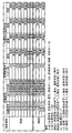
(4−1.当り種別と当り遊技について)
本実施形態のパチンコ遊技機1では、上記の特別図柄変動表示ゲームにて抽選される当りの種類、つまり大当り抽選対象となる当りの種別として、図示のように、大当り種別に属する「大当り1〜11」や、小当り種別に属する「小当り1」などの複数種類の当りが設けられている。上記「大当り」とは条件装置の作動契機となる当りであり、「小当り」とは条件装置の作動契機とならない「非大当り」種別に属する当りである。ここで「条件装置」とは、その作動が、ラウンド遊技を行うための役物連続作動装置(特別電動役物を連続作動させる装置)作動に必要な条件とされている装置で、特定の特別図柄の組合せが表示され、または遊技球が大入賞口内の特定の領域を通過した場合(役物連続作動装置が作動中に大入賞口に入賞したものを除く)に作動するものをいう。したがって、小当りの場合は、ラウンド遊技自体は実行されず、大当りによるラウンド遊技と同一または酷似する動作態様、あるいは、大当りによるラウンド遊技とは全く異なる動作態様で大入賞口の開閉動作が制御されるが(疑似的なラウンド遊技)、小当りも大当りと同様に、大入賞口の開閉動作を伴う特別遊技状態への移行契機(当り遊技の発生契機)となる当選種別であり、この点で、小当りは単なる「ハズレ」とは性質を異にする。
(4-1. About hit type and hit game)
In the
ここで図示の‘当りの内容’の欄の「16R」、「8R」、「4R」、「2R」などの表記は、それぞれ、大当りに係る規定ラウンド数(最大ラウンド数)を示す。また同欄の「長開放」の表記は、1回のラウンド遊技における大入賞口の最大開放時間が、大入賞口への入賞数が最大入賞数(9個)に達する可能性が見込める「長開放時間(たとえば、29.8秒)」に設定される大当りを示し、「短開放」とは大入賞口の最大開放時間が「長開放」よりも短い「短開放時間(たとえば、1.8秒)」に設定される大当りを示す。したがって、大当り遊技中の利益状態については、最大ラウンド数が相対的に多いほど高くなり、また短開放よりも長開放の方が高くなる。たとえば、大当り1(12R長開放確変大当り)であれば、最大ラウンド数が12R、各ラウンド遊技の大入賞口が長開放パターンで開閉動作される大当りであることを示す。 Here, the notations such as "16R", "8R", "4R", and "2R" in the "contents of hit" column in the figure indicate the specified number of rounds (maximum number of rounds) related to the jackpot, respectively. In addition, the notation of "long opening" in the same column means that the maximum opening time of the large winning opening in one round game is expected to reach the maximum number of winnings (9). Indicates a jackpot set to "opening time (for example, 29.8 seconds)", and "short opening" means "short opening time (for example, 1.8)" in which the maximum opening time of the big winning opening is shorter than "long opening". Indicates the jackpot set in "seconds)". Therefore, the profit status during the big hit game becomes higher as the maximum number of rounds is relatively larger, and the long opening is higher than the short opening. For example, if the jackpot is 1 (12R long open probability variation jackpot), it means that the maximum number of rounds is 12R, and the jackpot of each round game is a jackpot that is opened and closed in a long opening pattern.
また図4には、各大当りに当選した場合、その当選時の遊技状態に応じた大当り遊技終了後の遊技状態の移行先を示している。たとえば、大当り1(12R長開放確変大当り)は、その当選時の遊技状態がいずれの遊技状態であっても「確変状態(高確率、電サポ有り)」に移行され、大当り7(2R短開放潜確大当り)は、その当選時の遊技状態が通常状態の場合には「潜確状態(高確率、電サポ無し)」に移行され、潜確・時短・確変状態の場合にはいずれも「確変状態に」移行される。また、大当り2、4、6、9、11は、いずいれも時短状態(低確率、電サポ有り)への移行契機となる大当りであり、大当り2、4、9は「時短A(時短回数100回)」に移行され、大当り6、11は「時短B(時短回数50回)」に移行される。また、大当り中は大入賞口が開閉される当り遊技(大当り遊技)が発生するが、上記各機能については全ての機能が非作動とされ、基本的には、上記通常状態と同じ遊技状態下に置かれる。なお、他の大当りについては、図4に示す通りである。
Further, FIG. 4 shows the transition destination of the game state after the end of the big hit game according to the game state at the time of winning when each big hit is won. For example, jackpot 1 (12R long open probability variation jackpot) is shifted to "probability variation state (high probability, with electric support)" regardless of the gaming state at the time of winning, and jackpot 7 (2R short opening). The latent probability jackpot) is shifted to the "latent probability state (high probability, no electric support)" when the game state at the time of winning is the normal state, and in the case of the latent probability, time reduction, and probability change state, " It shifts to the probabilistic state. In addition, the
本実施形態に係る「潜確状態」、「確変状態」、「時短状態」については、特別図柄変動表示ゲーム(特別図柄の変動回数)の実行回数が、所定の規定回数(特別図柄変動表示ゲーム1および2(特別図柄1および2の変動回数)の合計実行回数)終了するまで継続され、その規定回数内で大当り(小当りを除く)に当選することなく特別図柄変動表示ゲームが終了すると、次ゲームから通常状態(通常遊技状態)に移行されるようになっている。本実施形態の場合、潜確状態または確変状態は、所定の規定回数(ST規定回数:ここでは、65536回)が設定される(回数切り確変タイプ(ST機タイプ))。また、時短状態も、所定の規定回数(時短回数:時短Aの場合は100回、時短Bの場合は50回)が設定される。なお、潜確状態または確変状態ついては上記ST規定回数を定めるのではなく、次回大当りが当選するまで高確率状態を継続させる「一般確変機タイプ」としてもよい。また時短回数については、適宜な回数を設定することができる。また潜確状態または確変状態への移行については、大当り遊技中に、大入賞口内の特定領域に遊技球が入球(通過)したことをその移行条件とすることができる(V確変機タイプ)。
Regarding the "latent state", "probability change state", and "time saving state" according to the present embodiment, the number of times the special symbol variation display game (number of changes of the special symbol) is executed is a predetermined number of times (special symbol variation display game). It continues until the end of 1 and 2 (total number of executions of
ただし、小当りに当選した場合は、その小当り当選時の内部遊技状態がそのまま継続され、小当り当選に起因した内部遊技状態の移行制御は行われない。したがって、小当り当選時の遊技状態とその小当り遊技後の遊技状態とは、いずれも同じ遊技状態となる。たとえば、確変状態中に小当り1に当選した場合、その当り遊技中および当り遊技後も確変状態が継続される。この点、遊技状態の移行制御が行われる上述の大当りとは性質を異にする。このような小当りの性質を利用して、たとえば、小当り1による当り遊技と、特定の大当り(ここでは、大当り7(2R短開放潜確大当り))による当り遊技の大入賞口の動作態様を実質的に同一とし、また当り中の演出も実質的に同一とし、さらに、これら当り遊技後に同一の演出モード(後述のCZ演出モード)に移行させれば、今回当選した当り種別を秘匿することができる。
However, when a small hit is won, the internal gaming state at the time of the small hit is continued as it is, and the transition control of the internal gaming state due to the small hit is not performed. Therefore, the game state at the time of winning the small hit and the game state after the small hit game are both the same game state. For example, if a
本実施形態では、通常状態中において、「小当り1」と「大当り7」に当選した場合とで、所定期間(たとえば、特別図柄の変動回数4回終了するまで)、同じCZモード(CZ演出モード)に移行させる。これにより、今回当選した大当りが、大当り7であるのか小当り1であるのかが秘匿される。つまり、大当り抽選確率状態が秘匿され、CZ演出モード中において高確率状態の期待感を高めることができる。なお、小当り1の当選を契機に移行されるCZ演出モードの実体は、内部遊技状態が‘通常状態’の「CZ(CZ(通常))」であり、大当り7の当選を契機に移行されるCZ演出モードの実体は、内部遊技状態が‘潜確状態’の「CZ(CZ(潜確))」である。
In the present embodiment, in the normal state, the same CZ mode (CZ effect) is used for a predetermined period (for example, until the number of fluctuations of the special symbol is completed 4 times) when the "
なお、図示はしていないが、大当りおよび小当りではない「ハズレ」種別として、図柄抽選(当選種別抽選)確率がそれぞれ異なる複数種類のハズレ(たとえば、ハズレA、B、C)が設けられている。また、小当りは特図1側に1種類の小当り1が設けられているが、本発明はこれに限らず、1または複数種類の小当りを特図1側および/または特図2側に設けてもよい。また、大当りおよび小当りの種類については、遊技性に応じて適宜定めることができる。また、当選時の遊技状態によらず、通常状態に移行させる「通常大当り」を設けてもよい。
Although not shown, a plurality of types of losses (for example, losses A, B, C) having different symbol lottery (winning type lottery) probabilities are provided as "loss" types that are not big hits and small hits. There is. Further, as for the small hit, one type of
<5.演出について>
(5−1.演出モード)
次に、演出モード(演出状態)について説明する。本実施形態のパチンコ遊技機1には、遊技状態に関連する演出をなす複数種類の演出モードが設けられており、遊技状態の移行に対応して、各演出モード間を移行制御可能に構成されている。演出モードには、「通常状態」の場合は「通常演出モード」、「CZ」の場合は「CZ演出モード」、「潜確状態」の場合は「潜確演出モード」、「確変状態」の場合は「確変演出モード」、「時短状態」の場合は「時短演出モード」といった各遊技状態に応じた複数種類の演出モードが設けられている。なお、時短演出モードは、時短Aと時短Bとで共通の時短演出モードを設けてもよいし、異なる演出モードであってもよい。
<5. About production>
(5-1. Production mode)
Next, the effect mode (effect state) will be described. The
演出制御部24(CPU241)は、複数種類の演出モード間を移行制御する機能部(演出状態移行制御手段)を有する。演出制御部24は、主制御部20(CPU201)から送られてくる特定の演出制御コマンド、具体的には、現在の遊技状態を指定したり、遊技状態が移行される旨を指定したりする演出制御コマンドに基づいて、主制御部20側の遊技状態と整合性を保つ形で、複数種類の演出モード間を移行制御可能に構成されている。斯様な特定の演出制御コマンドには、変動パターン指定コマンド、遊技状態指定コマンド、客待ち中コマンド、当り中に送信される所定のコマンド(大当り開始を指定する大当り開始コマンドや、大当り終了を指定する大当り終了コマンド)などがある。また演出制御部24は、遊技状態に関連した演出モードを管理する機能部(演出状態管理手段)を有し、現在の演出モードを管理する。
The effect control unit 24 (CPU 241) has a function unit (effect state transition control means) for transition control between a plurality of types of effect modes. The
(5−2.各演出モード下の演出)
また各演出モードでは、遊技者がどのような遊技状態に対応した演出モード下に滞在しているのかを把握できるように、各演出モードのそれぞれにおいて、バックグラウンドとしての背景表示が、異なる背景画像演出が現出されるようになっている。また上記した「背景演出」を変化させて遊技状態を示唆するものに限らず、各演出モードに対応した異なる絵柄の装飾図柄を利用したり、音演出や光演出などにより遊技状態を示唆することもできる。また各演出モードは1種類に限らず、複数種類設けることができる。
(5-2. Production under each production mode)
Further, in each production mode, the background display as the background is different in each production mode so that the player can grasp what kind of game state the player is staying in in the production mode. The production has come to appear. In addition to changing the above-mentioned "background effect" to suggest the game state, it is possible to use decorative patterns with different patterns corresponding to each effect mode, or to suggest the game state by sound effect or light effect. You can also. Further, each effect mode is not limited to one type, and a plurality of types can be provided.
(5−3.予告演出)
次に、予告演出について説明する。演出制御部24は、主制御部20からの演出制御コマンドの内容、具体的には、少なくとも変動パターン指定コマンドに含まれる変動パターン情報に基づき、現在の演出モードと大当り抽選結果とに関連した様々な「予告演出」を現出制御可能に構成されている。このような予告演出は、当り種別に当選したか否かの当選期待度を示唆(予告)し、遊技者の当り種別への当選期待感を煽るための「煽り演出」として働く。予告演出として代表的なものは、「リーチ演出(リーチ変動パターンに係る演出態様)」の他、「疑似連演出」や「遊技者参加型演出」や「先読み予告演出」などがあり、種々の予告演出によりゲーム内容を盛り上げるようになっている。演出制御部24は、これら予告演出を実行(現出)制御可能な予告演出制御手段を含む。
(5-3. Notice production)
Next, the advance notice production will be described. The
「リーチ演出」とは、リーチ状態を伴う演出態様をいい、具体的には、リーチ状態を経由してゲーム結果を導出表示しうる演出態様をいう。リーチ演出には、当選期待度に関連付けられた複数種類のリーチ演出が含まれる。たとえば、ノーマルリーチ(Nリーチ)が出現した場合に比べて、当選期待度が相対的に高まるものがある。このようなリーチ演出を‘スーパーリーチ(SPリーチ)’という。この「SPリーチ」の多くは、遊技者の当選期待感を煽るべく、Nリーチよりも相対的に長い演出時間(変動時間)を持つ。本実施形態のNリーチには「Nリーチ1〜2」などの複数種類のNリーチを含み、またSPリーチには「弱SPリーチ、中SPリーチ、強SPリーチ」などの複数種類のSPリーチが含まれる。なお、同種のリーチ間の当選期待度の関係については、「Nリーチ1<Nリーチ2」、「弱SPリーチ<中SPリーチ<強SPリーチ」という関係を持たせている。なお、実際の大当り当選期待度は、他の予告演出が伴うか否かに応じて変化する。このため、たとえば、弱SPリーチが出現した場合であっても、大当り当選期待度の高い予告演出が絡めば、中SPリーチと同等もしくはそれ以上の当選期待度となりうる。 The “reach effect” refers to an effect mode accompanied by a reach state, and specifically, an effect mode in which a game result can be derived and displayed via the reach state. The reach effect includes a plurality of types of reach effect associated with the winning expectation. For example, there are cases where the winning expectation is relatively higher than when normal reach (N reach) appears. Such a reach production is called "super reach (SP reach)". Most of these "SP reach" have a relatively longer production time (variable time) than the N reach in order to fuel the player's expectation of winning. The N reach of the present embodiment includes a plurality of types of N reach such as "N reach 1 and 2", and the SP reach includes a plurality of types of SP reach such as "weak SP reach, medium SP reach, and strong SP reach". Is included. Regarding the relationship of the winning expectation between the same type of reach, there is a relationship of "N reach 1 <N reach 2" and "weak SP reach <medium SP reach <strong SP reach". The actual expectation of winning a big hit changes depending on whether or not other notice effects are involved. For this reason, for example, even when a weak SP reach appears, the winning expectation level can be equal to or higher than that of the medium SP reach if a notice effect with a high expectation for a big hit is involved.
「疑似連演出」とは、装飾図柄の疑似的な連続変動表示状態(疑似変動)を伴う演出態様をいう。この「疑似変動」とは、装飾図柄変動表示ゲーム中において、装飾図柄の一部または全部を一旦仮停止状態とし(仮停止状態中はリーチ状態であってもよいし、非リーチ状態であってもよい)、その仮停止状態から装飾図柄の再変動表示動作を実行する、といった表示動作を1回または複数回繰り返す変動表示態様をいう。この点、複数回の図柄変動表示ゲームに跨って展開されうるような後述の「先読み予告演出」とは異なる。斯様な「疑似連」は、基本的には、疑似変動回数が多くなるほど当り当選期待度が高まるようにその発生率が定められており、たとえば、疑似変動回数が相対的に多いほど、当選期待度の高い予告演出(SPリーチ等)の発生期待度が高まるようになっている。 The "pseudo-continuous production" refers to a production mode accompanied by a pseudo continuous fluctuation display state (pseudo-variation) of a decorative pattern. This "pseudo-variation" means that a part or all of the decorative symbol is temporarily stopped in the decorative symbol variation display game (during the temporary stop state, it may be in the reach state or the non-reach state). A variable display mode in which a display operation such as executing a re-variable display operation of a decorative symbol from the temporarily stopped state is repeated once or a plurality of times. In this respect, it is different from the "look-ahead notice effect" described later, which can be developed over a plurality of symbol variation display games. Basically, the rate of occurrence of such "pseudo-ream" is set so that the higher the number of pseudo-variations, the higher the expectation of winning. For example, the more the number of pseudo-variations, the more the winning. Expectations for the occurrence of highly expected notice effects (SP reach, etc.) are increasing.
「遊技者参加型演出」とは、いわゆる「ボタン予告演出」に属する演出態様であり、遊技者が演出ボタン13(操作手段)に対して所定の操作(たとえば、押圧、長押し、連打等の操作)に基づき、演出の内容が変化し得る予告演出態様である。遊技者参加型演出では、所定のボタン有効期間中になると、演出ボタン13に対して所定の操作を指示する操作指示演出が現出され、ボタン有効期間中に演出ボタン13が操作されたことに基づき、現出中の演出態様が他の演出態様(操作時演出)に変化し(たとえば、キャラクタ表示が変化する、特殊な効果音や光演出が発生する等)、操作前後の演出態様(演出内容)に応じて、当選期待度を予告する。
The "player participation type production" is a production mode belonging to the so-called "button notice production", in which the player performs a predetermined operation (for example, pressing, long pressing, repeated hitting, etc.) on the production button 13 (operation means). This is a notice production mode in which the content of the production can be changed based on the operation). In the player participation type effect, an operation instruction effect for instructing the
「先読み予告演出」とは、未だ図柄変動表示ゲームの実行(特別図柄の変動表示動作)には供されていない作動保留球(未消化の作動保留球)について、主に、保留表示態様や先に実行される図柄変動表示ゲームの背景演出等を利用して、当該作動保留球に関する当選期待度を事前に報知しうる演出態様である。 The "look-ahead notice effect" is mainly for the hold display mode and the destination of the operation hold ball (undigested operation hold ball) that has not yet been used for the execution of the symbol change display game (special symbol change display operation). This is an effect mode in which the winning expectation degree regarding the operation holding ball can be notified in advance by using the background effect of the symbol variation display game executed in.
図5を用いて、上記先読み予告演出を含め、本実施形態に係る液晶表示装置の画面表示について説明する。図5は、本実施形態に係る液晶表示装置36の画面表示の説明に供する説明図である。
The screen display of the liquid crystal display device according to the present embodiment will be described with reference to FIG. 5, including the pre-reading notice effect. FIG. 5 is an explanatory diagram provided for explaining the screen display of the liquid
液晶表示装置36の画面内の一部に(図示では、装飾図柄の表示エリアの下方)、特別柄1作動保留球の個数を表示する保留表示領域76と、特図2作動保留球の個数を表示する保留表示領域77とが設けられており、作動保留球の有無に関して、その旨を点灯状態(作動保留球あり:図示の「○(白丸印)」)あるいは消灯状態(作動保留球なし:図示の破線の丸印)にて、現在の作動保留球数に関する情報が報知される。
In a part of the screen of the liquid crystal display device 36 (in the figure, below the display area of the decorative symbol), a
この作動保留球の有無に関する表示(以下「保留表示」と称する)は、その発生順(入賞順)に順次表示され、各保留表示領域76、77において、一番左側の作動保留球が、当該保留表示内の全作動保留球のうち時間軸上で一番先に生じた(つまり最も古い)作動保留球として表示される。本実施形態では、図示のように、液晶表示装置36の画面内の一部に、最大保留記憶数と同数(4個)だけ設けた保留アイコン(アイコン画像)からなる保留表示部a1〜d1(特図図柄1側に対応)、a2〜d2(特図図柄2側に対応)が設けられている。また、保留表示領域76、77の左側には、現に特別図柄変動表示ゲームに供されている作動保留球を示すための変動中表示領域78が設けられている。この実施形態の場合、変動中表示領域78は、受座Jのアイコン上に、現在ゲームに供されているゲーム実行中保留Kのアイコンが載る形の画像が現れるように構成されている。すなわち、特別図柄1または特別図柄2の変動表示が開始される際に、保留表示領域76、77に表示されていた最も古い保留a1またはa2のアイコン(アイコン画像)が、ゲーム実行中保留Kのアイコンとして、変動中表示領域78おける受座Jのアイコン上に移動し、その状態が所定の表示時間にわたり維持される。
The display regarding the presence or absence of the operation holding ball (hereinafter referred to as "hold display") is sequentially displayed in the order of occurrence (winning order), and in each of the
作動保留球が発生した場合、演出制御コマンドとして、大当り抽選結果に関連する先読み判定情報と、先読み判定時の作動保留球数(今回発生した作動保留球を含む現存の作動保留球数)とを特定可能な「保留加算コマンド」が演出制御部24に対して送信される(後述の図21のステップS323参照)。 When an operation-holding ball is generated, as an effect control command, the look-ahead determination information related to the jackpot lottery result and the number of operation-holding balls at the time of the look-ahead judgment (the number of existing operation-holding balls including the operation-holding ball generated this time) are input. A identifiable "hold addition command" is transmitted to the effect control unit 24 (see step S323 in FIG. 21 described later).
上記先読み判定情報とは、具体的には、主制御部20において、作動保留球が図柄変動表示ゲームに供される際に実行される大当り抽選結果(変動開始時の大当り抽選結果)にや、変動開始時の変動パターンを先読み判定した際に得られる先読み変動パターンに関する遊技情報をいう。したがって、この先読み判定情報には、少なくとも変動開始時の当落抽選結果の先読み判定結果(先読み当落結果)情報が含まれ、その他、図柄抽選結果の先読み判定結果(先読み図柄結果)情報や、変動開始時の変動パターンに関する先読み判定結果(先読み変動パターン)情報を含ませることができる。如何なる情報を含む保留加算コマンドを演出制御部24に送るかについては、報知する予告内容をどのようなものにするかに応じて適宜定めることができる。なお、作動保留球発生時の先読み判定により得られる「先読み変動パターン」は、必ずしも作動保留球が変動表示動作に供されるときに得られる「変動開始時の変動パターン」そのものではある必要はない。たとえば、変動開始時に「Nリーチ1」を指定する変動パターンのケースであれば、先読み変動パターンにより指定される内容は「Nリーチ1」というリーチの種類そのものではなく、その骨子である「Nリーチ種(Nリーチ1またはNリーチ2)」である旨を指定してもよい。
Specifically, the pre-reading determination information includes the jackpot lottery result (big hit lottery result at the start of fluctuation) executed when the operation holding ball is provided to the symbol variation display game in the
演出制御部24が保留加算コマンドを受信すると、これに含まれる先読み判定情報に基づき、上記保留表示に関連する表示制御処理の一環として、「先読み予告演出」に関する演出制御処理を行う。具体的には、保留加算コマンドに含まれる情報に基づいて、先読み予告演出の実行可否を抽選する先読み予告抽選を行い、これに当選した場合、先読み予告の演出シナリオが決定され、そのシナリオに従い、当選期待度に応じた先読み予告演出を現出させる。上記先読み予告抽選の当選確率は、「ハズレ」よりも「大当り」の方が、また当選期待度が相対的に高いリーチ種別の場合の方が高確率となっている。よって、先読み予告演出が発生するか否かにより、当り種別への当選期待度が示される。
When the
この実施形態では、先読み予告抽選に当選した場合に、保留表示部a1〜d1、a2〜d2の保留アイコンのうちで、その先読み予告対象となった保留アイコンが、たとえば、通常の保留表示(通常保留表示態様)の白色から、予告表示の青色、緑色、赤色、虹色などの特殊な保留色や色彩の保留表示(特別保留表示態様)に変化するといった「保留表示変化系」の先読み予告演出(保留変化予告)が行われる。図5では、ハッチングされた保留表示部b1の作動保留球が、特別保留表示に変化した例を示している。ここで、保留アイコンの青色、緑色、赤色、虹色の表示は、この色の順に、当選期待度が高いことを意味しており、特に虹色の保留アイコンの表示は、大当り確定(当確)表示となるプレミアム的な保留アイコン(当確保留予告)となっているしたがって、この保留表示部が作動保留数を表示する保留表示手段として働く。しかし、先読み予告演出を実行する場合は、保留表示部a1〜d1、a2〜d2のうちの該当する一の保留表示部の保留表示態様を所定の先読み予告表示態様(特別保留表示態様)に変更し、これにより先読み予告演出を現出させる手段として働く。 In this embodiment, when the look-ahead notice lottery is won, among the hold icons of the hold display units a1 to d1 and a2 to d2, the hold icon targeted for the look-ahead notice is, for example, a normal hold display (normally). Pre-reading notice effect of "hold display change system" such as changing from white of hold display mode) to special hold color such as blue, green, red, rainbow color of notice display and hold display of color (special hold display mode) (Pending change notice) will be held. FIG. 5 shows an example in which the hatched hold display unit b1 has changed to a special hold display. Here, the display of the blue, green, red, and rainbow colors of the hold icon means that the winning expectation is high in the order of this color, and in particular, the display of the rainbow-colored hold icon is a big hit confirmation (correct). Since it is a premium hold icon (notice of reservation) to be displayed, this hold display unit functions as a hold display means for displaying the number of operation holds. However, when executing the look-ahead notice effect, the hold display mode of one of the hold display units a1 to d1 and a2 to d2 is changed to a predetermined look-ahead notice display mode (special hold display mode). However, this works as a means to bring out the look-ahead notice effect.
現存する作動保留球は、図柄変動表示ゲームの実行を契機に順次消化される。このとき、作動保留球が1つ消化したことを表現するべく、現存する作動保留球に対応した保留表示部の表示位置を繰り上げ移行し(順次左側にシフト)、その表示個数が減じられるといった表示制御(シフト表示)が行われるが、上記した特別保留表示は、この間も保留表示の表示位置を変えながら連続的に表示され続ける。またゲーム実行中保留Kが受座J上に載る際には、基本的には、保留表示領域76、77での保留表示態様と同じ表示態様が維持され、今回の図柄変動表示ゲームに係る作動保留球を対象とした先読み予告表示態様が当該ゲーム中においても遊技者に報知される。
The existing operation hold balls are sequentially digested when the symbol variation display game is executed. At this time, in order to express that one operation-holding ball has been digested, the display position of the hold display unit corresponding to the existing operation-holding ball is moved forward (shifted to the left side in sequence), and the number of the display is reduced. Although control (shift display) is performed, the above-mentioned special hold display continues to be displayed continuously while changing the display position of the hold display during this period. Further, when the hold K during game execution is placed on the seat J, basically, the same display mode as the hold display mode in the
また図5に示す液晶画面内の右下隅には、装飾図柄や予告演出などのメイン演出とは別のサブ的な演出(サブ演出)の表示領域として、特別図柄や普通図柄の変動表示動作に関するサブ表示領域75を設けてあり、小さい6つの升目により示されている。なお図示では、説明の便宜のために、サブ表示領域75を誇張して示してある。
Further, in the lower right corner of the liquid crystal screen shown in FIG. 5, as a display area for a sub-effect (sub-effect) different from the main effect such as a decorative symbol or a notice effect, a variable display operation of a special symbol or a normal symbol is related. A
このサブ表示領域75に係る6つの升目のうち、上段と中段は特別図柄に係る表示領域であり、下段は普通図柄に関する表示領域である。具体的には、上段の左升目は特図1作動保留球数を表示する第1保留個数表示領域であり、上段の右升目は特図1が変動表示中であるか否かを表示する第1変動有無表示領域となっており、また中段の左升目は特図2作動保留球数を表示する第2保留個数表示領域、中段の右升目は特図2が変動表示中であるか否かを表示する第2変動有無表示領域となっている。本実施形態では、第1保留個数表示領域および第2保留個数表示領域では保留個数をアラビア数字で示し、第1変動有無表示領域および第2変動有無表示領域では、図示はしていないが、図柄変動中である場合には「⇔」が点滅表示され、図柄が停止中である場合には「×」「△」「○」のいずれかが表示される。この「×」「△」「○」の表示は、「×」はハズレ図柄、「△」は小当り図柄、「○」は大当り図柄での停止状態を示す。したがって、これら「×」「△」「○」のいずれかが表示されている場合は、特別図柄が非変動状態(停止表示状態)である。また上記下段の左升目は、普図作動保留球数を表示する第3保留個数表示領域であり、下段の右升目は普図が変動表示中であるか否かを表示する第3変動有無表示領域となっている。第3保留個数表示領域では普図作動保留球数をアラビア数字で示し、第3変動有無表示領域では、図示はしていないが、図柄変動中である場合には「赤丸」と「青丸」とが交互に表示され、図柄が停止中である場合には「○(白丸)」「●(黒丸)」のいずれかが表示される。「○」はハズレ図柄、「●」は普図当り図柄での停止状態を示す。図示では、特図1作動保留球数「3」個、特図1が非変動状態(ハズレ図柄で停止)、特図2作動保留球数「0」個、特図2が非変動状態(ハズレ図柄で停止)、普図作動保留球数「1」個、普図が非変動状態(当り図柄で停止)の例を示している。
Of the six squares related to the
上記第1変動有無表示領域と第2変動有無表示領域にて表示される画像は、特図1と特図2の変動表示中か否かを示すことから、3つの装飾図柄とは別の4つ目の図柄として、特図1または特図2の「第4図柄」と称する。また第3変動有無表示領域にて表示される演出画像は、普通図柄表示装置39aによる普通図柄の変動表示と時間的に同調して画像による普通装飾図柄を変動表示するもので、第3変動有無表示領域は、普通装飾図柄変動表示ゲームの表示領域となっている。
Since the images displayed in the first fluctuation presence / absence display area and the second fluctuation presence / absence display area indicate whether or not the fluctuation display of the special figures 1 and 2 is in progress, 4 different from the three decorative symbols As the second symbol, it is referred to as the "fourth symbol" of the special figure 1 or the special figure 2. Further, the effect image displayed in the third variation presence / absence display area is a variation display of the ordinary decorative symbol by the image in time with the variation display of the ordinary symbol by the ordinary
(5−4.演出手段)
遊技機1における各種の演出は、遊技機に配設された演出手段により現出される。斯様な演出手段は、視覚、聴覚、触覚など、人間の知覚に訴えることにより演出効果を発揮し得る刺激伝達手段であれば良く、装飾ランプ45やLED装置などの光発生手段(光演出手段)、スピーカ46などの音響発生装置(音演出手段)、液晶表示装置36などの演出表示装置(表示手段)、操作者の体に接触圧を伝える加圧装置、遊技者の体に風圧を与える風圧装置、ないし、その動作により視覚的演出効果を発揮する可動体役物などは、その代表例である。ここで演出表示装置は、画像表示装置と同じく視覚に訴える表示装置であるが、画像によらないもの(たとえば、7セグメント表示器)も含む点で画像表示装置と異なる。画像表示装置と称する場合は主として画像表示により演出を現出するタイプを指し、7セグメント表示器のように画像以外により演出を現出するものは、上記演出表示装置の概念の中に含まれる。
(5-4. Directing means)
Various effects in the
<主制御部側の処理:図6A〜図36>
次に図6A〜図36を参照して、本実施形態の主制御部20側における遊技動作処理について説明する。主制御部20側の処理は、無限ループ状のメイン処理(主制御側メイン処理:図6Aおよび図6B)と、CTCからの定時割込みで起動されるタイマ割込処理(主制御側タイマ割込処理:図17)とを含んで構成される。
<Processing on the main control unit side: FIGS. 6A to 36>
Next, with reference to FIGS. 6A to 36, the game operation processing on the
<6.主制御側メイン処理:図6Aおよび図6B>
図6Aおよび図6Bを参照して、主制御部20側のメイン処理(主制御側メイン処理)について説明する。
<6. Main control side main processing: FIG. 6A and FIG. 6B>
The main process on the
図6Aおよび図6Bは、主制御側メイン処理の詳細を示すフローチャートである。以下では、主制御側メイン処理の説明に際し、本発明と関係の深い処理について、図31Aおよび図31Bに示すソースコード(場有により「プログラム」とも称する場合がある)を参照しながら説明する。ただし図31Aおよび図31Bは、主制御側メイン処理のソースコードの一部をメモリ上の記憶順序に沿って記載したものを例示したものであり、また、そのソースコードの記載欄の右側の矢印は、設定キースイッチ94、扉開放センサ61、RAMクリアスイッチ98(設定キースイッチ信号、扉開放信号、RAMクリアスイッチ信号)の入力状態(ON/OFF状態)の組合せに応じて実行される各種の処理ルート(後述の「設定変更処理ルート」、「RAMクリア処理ルート」、「設定確認処理ルート」、「バックアップ復帰処理ルート」、「再電源投入待ち処理(RAMエラー処理)ルート」)について、その処理ルートで実行される処理内容とその処理の実行順序とを、ソースコードに対応して示したものである。なお、いずれの処理ルートも、後述のステップS011〜ステップS014の処理が共通して実行され、その後、設定キースイッチ94、扉開放センサ61、RAMクリアスイッチ98のON/OFF状態の組合せに応じて、処理が分岐(条件分岐)されるようになっている。
6A and 6B are flowcharts showing the details of the main processing on the main control side. In the following description of the main processing on the main control side, processing closely related to the present invention will be described with reference to the source code shown in FIGS. 31A and 31B (which may also be referred to as a “program” depending on the situation). However, FIGS. 31A and 31B exemplify a part of the source code of the main processing on the main control side described in the storage order in the memory, and the arrow on the right side of the description column of the source code. Is executed according to the combination of the input state (ON / OFF state) of the setting
主制御側メイン処理の開始契機には、停電状態や電源異常などからの復旧時におけるシステムリセットが生起した場合や、制御プログラムが暴走したことにより、ウォッチドッグタイマ(WDT)機能が発揮されてCPUが強制的にリセット(WDTリセット)された場合などがある。いずれの場合でも、主制御側メイン処理が開始されると、主制御部20(CPU201)は、まず、電源投入時処理の一環として、遊技動作開始に必要な初期設定処理を実行する(ステップS011)。 When the main control side starts the main process, the watchdog timer (WDT) function is exerted and the CPU is activated when a system reset occurs when recovering from a power failure or power failure, or when the control program runs out of control. May be forcibly reset (WDT reset). In any case, when the main control side main process is started, the main control unit 20 (CPU201) first executes the initial setting process necessary for starting the game operation as a part of the power-on process (step S011). ).
(7.初期設定処理:図7)
先ず、図7および図31Aの初期設定処理の欄(SPa1〜SPa26)を参照して、上記ステップS011の初期設定処理について説明する。図7は、初期設定処理の詳細を示すフローチャートである。
(7. Initial setting process: Fig. 7)
First, the initial setting process of step S011 will be described with reference to the columns (SPa1 to SPA26) of the initial setting process of FIGS. 7 and 31A. FIG. 7 is a flowchart showing the details of the initial setting process.
図7において、システムリセットやWDTリセットが発生すると、CPU201は、起動時の初期設定として、まず自らを割込み禁止状態に設定する(ステップS051、SPa1)。
In FIG. 7, when a system reset or a WDT reset occurs, the
次いで、スタックポインタSPの設定を行う(ステップS052)。ここでは、スタックポインタSPに00FFHをセット(設定)する(SPa2)。これにより、RAM203内のアドレス00FEH番地以下が領域内プログラム用のスタック領域、01FEH番地以下が領域外プログラム用のスタック領域として設定される(図29参照)。
Next, the stack pointer SP is set (step S052). Here, 00FFH is set (set) in the stack pointer SP (SPa2). As a result, the address 00FEH or less in the
次いで、後述する第1電源異常チェック処理(_VDDCHK)でのスタック使用に備えて、RAMのプロテクトおよび禁止領域を無効にする(ステップS053、SPa3)。RAMプロテクトとは、誤作動や誤操作などによるRAMに対する書き換え防止機能である。RAMプロテクトの動作は、次のようになる。電源復旧時等のシステムリセットやWDTリセットが発生した後はRAMのプロテクトが有効(RAMプロテクト状態)となっている。RAMのプロテクトが有効に設定されている場合にはRAMからデータを読み出すことができるが、RAMにデータを書き込むことができない。したがってRAMにデータを書き込む場合には、RAMのプロテクトを無効に設定する必要がある。本実施形態では、RAMプロテクトレジスタ(RAMPT)の値に応じて、RAMプロテクトとRAMアクセス禁止領域の有効/無効が制御される。具体的には、RAMPTが00Hの場合には「RAMアクセス禁止領域無効、RAMプロテクト無効」に制御され、RAMPTが01Hの場合には「RAMアクセス禁止領域無効、RAMプロテクト有効」に制御され、RAMPTが80Hの場合には「RAMアクセス禁止領域有効、RAMプロテクトが無効」に制御される。また、RAMPTが81Hの場合に「RAMアクセス禁止領域有効、RAMプロテクト有効」に設定される。したがってここでは、RAMPTに00Hが設定される(SPa3)なお、システムリセットやWDTリセットが発生した場合には、RAMプロテクト状態に設定され(RAMPT=81H)、CTCやWDTは初期化される。ただし、システムリセットやWDTリセットが行われた場合でもRAMの記憶内容は変化しない。 Next, the protected and prohibited areas of the RAM are invalidated in preparation for the use of the stack in the first power supply abnormality check process (_ VDDCHK) described later (step S053, SPA3). RAM protection is a function for preventing rewriting of RAM due to malfunction or erroneous operation. The operation of RAM protection is as follows. RAM protection is effective (RAM protection state) after a system reset or WDT reset occurs when the power is restored. Data can be read from the RAM when RAM protection is enabled, but data cannot be written to the RAM. Therefore, when writing data to RAM, it is necessary to disable RAM protection. In the present embodiment, the validity / invalidity of the RAM protect and the RAM access prohibited area is controlled according to the value of the RAM protect register (RAMPT). Specifically, when the RAMPT is 00H, it is controlled to "RAM access prohibited area invalid, RAM protect invalid", and when the RAMPT is 01H, it is controlled to "RAM access prohibited area invalid, RAM protect enabled", and RAMPT When is 80H, it is controlled to "RAM access prohibited area is valid, RAM protection is invalid". Further, when the RAM PT is 81H, it is set to "RAM access prohibited area valid, RAM protect valid". Therefore, here, 00H is set in the RAMPT (SPa3). When a system reset or a WDT reset occurs, the RAMPT is set to the RAM protected state (RAMPT = 81H), and the CTC and WDT are initialized. However, even if the system reset or WDT reset is performed, the stored contents of the RAM do not change.
次いで、電源投入時の各種設定処理を実行する(ステップS054)。ここでは、設定変更中(たとえば、後述のステップS023の設定変更管理処理中)に電源のOFF/ONが行われた可能性を考慮して、まず、WAレジスタペア同士の排他的論理和(XOR)を求めた後(WA=0000H)(SPa4)、WAレジスタペアの値がゼロであることを利用して、枠用外部端子基板21のセキュリティ信号(外部出力用不正検出信号)出力用の情報端子に対応する外部端子ポート2(P_GAIBU2)をゼロクリアし、また設定表示器97に対するダイナミック点灯データおよび発射制御信号(払出制御基板28による発射許可信号ES)のON/OFFの設定等に利用されるLEDコモンポート(P_LEDCMN)とLEDコモンバッファ(W_LEDCMN)とを、それぞれゼロクリアする(SPa5〜SPa7)。これにより、セキュリティ信号用出力ポートが一旦クリアされるとともに、設定表示器97が消灯状態に設定される。また、発射制御信号がOFF状態に設定され、不用意な発射制御信号が出力されてしまうことを防止する。
Next, various setting processes at the time of turning on the power are executed (step S054). Here, in consideration of the possibility that the power is turned off / on during the setting change (for example, the setting change management process in step S023 described later), first, the exclusive OR (XOR) between the WA register pairs is taken into consideration. ) Is obtained (WA = 0000H) (SPa4), and the information for outputting the security signal (illegal detection signal for external output) of the external
次いで、第1電源異常チェック処理(_VDDCHK)を実行する(ステップS055)。ここでは、CALLV命令により、サブルーチンの第1電源異常チェック処理(_VDDCHK)を呼び出し実行する(SPa8)。この‘CALLV’命令とは、CALL命令の一種であるが、通常のCALL命令とは異なり、ROM202のCALL命令ベクタ領域のベクタテーブル(CALLV命令ベクタテーブル)にあらかじめ定義されたサブルーチンを実行させる命令となっている。詳述するに、通常のCALL命令(CALL mn)では、上位アドレスと下位アドレスとにより指定されるアドレス(mn番地)から始まるサブルーチンを実行する命令であるのに対し、CALLV命令では、アドレスの一部を構成する上位アドレスが特定値としてベクタテーブルに定められているため、下位アドレスのみを指定することで、サブルーチンのアドレスが特定可能となっており、CALL命令よりも少ないデータ量でサブルーチンを呼び出して実行することができる(CALLV命令は1バイト、通常のCALL命令は3バイト)、という特殊なCALL命令となっている。このため、CALLV命令は、使用頻度の高いサブルーチンを実行する場合に好適である。 Next, the first power supply abnormality check process (_ VDDCHK) is executed (step S055). Here, the first power supply abnormality check process (_ VDDCHK) of the subroutine is called and executed by the CALLV instruction (SPa8). This'CALLV'instruction is a kind of CALL instruction, but unlike a normal CALL instruction, it is an instruction to execute a subroutine defined in advance in the vector table (CALLV instruction vector table) of the CALL instruction vector area of ROM202. It has become. In detail, the normal CALL instruction (CALL mn) is an instruction that executes a subroutine starting from the address (mn address) specified by the upper address and the lower address, whereas the CALLV instruction is one of the addresses. Since the upper address that composes the part is defined in the vector table as a specific value, the address of the subroutine can be specified by specifying only the lower address, and the subroutine is called with a smaller amount of data than the CALL instruction. It is a special CALL instruction that can be executed (CALLV instruction is 1 byte, normal CALL instruction is 3 bytes). Therefore, the CALLV instruction is suitable for executing a frequently used subroutine.
(8.第1電源異常チェック処理:図8)
図8を参照して、上記第1電源異常チェック処理(_VDDCHK)について説明する。図8は第1電源異常チェック処理の詳細を示すフローチャートである。
(8. First power supply abnormality check process: Fig. 8)
The first power supply abnormality check process (_ VDDCHK) will be described with reference to FIG. FIG. 8 is a flowchart showing the details of the first power supply abnormality check process.
この第1電源異常チェック処理では、CPU201は、まずWDTをクリアし(ステップS701)、次いで、外部信号入力レジスタ(PINSTS)から、電断を示す電源異常信号の入力情報を取得する(ステップS702)。この外部信号入力レジスタ(PINSTS)の第0ビット〜第7ビット(b0〜b7)は、図示のように、第0ビット(b0)が上始動口センサ信号(上始動口センサ34a)のON/OFF状態を、第1ビット(b1)が下始動口センサ信号(下始動口センサ35a)のON/OFF状態を、第2ビット(b2)が電源異常信号(電圧降下信号)のON/OFF状態を示し、第3ビット(b3)〜第7ビット(b7)は、それぞれ未使用となっている。
In this first power supply abnormality check process, the
ステップS702において取得した電源異常信号がON状態(b2=1)である場合(ステップS703:YES)、図6Aに示す主制御部メイン処理の最初の処理(ステップS011)に移行し、電源投入時等と同じく、ステップS011以降の処理を順次実行する。しかし、取得した電源異常信号がON状態でない場合(ステップS703:NO)、正常動作であるとして、この第1電源異常チェック処理を抜けて、図7の内部機能レジスタ初期設定処理(ステップS056)に移行する。 When the power supply abnormality signal acquired in step S702 is in the ON state (b2 = 1) (step S703: YES), the process proceeds to the first process (step S011) of the main control unit main process shown in FIG. 6A, and when the power is turned on. And so on, the processes after step S011 are sequentially executed. However, when the acquired power supply abnormality signal is not in the ON state (step S703: NO), it is assumed that the operation is normal, and the first power supply abnormality check process is exited, and the internal function register initial setting process (step S056) of FIG. 7 is performed. Transition.
再び図7に戻り、電源異常信号がON状態でない場合には、内部機能レジスタ初期設定処理を実行する(ステップS056、SPa9〜SPa13)ここでは、マイクロコンピュータの各部を含めてCPUの内部機能レジスタ値に関する初期設定処理を行う。図31Aに示すD_REGINI1には、CPU内部の各種内部機能レジスタ値に関する初期値が定義されており、SPa9〜SPa13により、たとえば、RAMプロテクトレジスタの他、CTC、WDT、送受信用シリアルポート、割込みモード(割込みモード2に設定)、割込み優先順位、内部ハード乱数および内部ソフト乱数等に関する内部機能レジスタが初期値に設定されるようになっている。 Returning to FIG. 7 again, if the power supply abnormality signal is not in the ON state, the internal function register initial setting process is executed (step S056, Spa9 to Spa13). Here, the internal function register value of the CPU including each part of the microcomputer is executed. Perform the initial setting process for. In D_REGINI1 shown in FIG. 31A, initial values related to various internal function register values inside the CPU are defined, and according to SPA9 to Spa13, for example, in addition to the RAM protect register, CTC, WDT, serial port for transmission / reception, interrupt mode ( (Set to interrupt mode 2), interrupt priority, internal hard random number, internal soft random number, and other internal function registers are set to initial values.
次いで、サブ制御基板(演出制御部24)の起動待ち時間を管理する処理として、ステップS057〜S062の処理を実行する。具体的には、まず上述の起動待ち時間の設定処理として、Bレジスタにループ回数(たとえば、240)をセットし(ステップS057、SPa14)、WAレジスタペアに起動待ち用カウント値(たとえば、13880)をセットする(ステップS058、SPa15)。そして、起動待ち時間の減算処理として、WAレジスタペアの値をデクリメントし(ステップS059、SPa16)、WAレジスタペアの値がゼロになるまで待ち(ステップS060:NO、SPa17)、WAレジスタペアの値がゼロになったならば(ステップS060:YES、SPa17)、図8の第1電源異常チェック処理を実行し(ステップS061、SPa18)、ループ回数(Bレジスタの値)がゼロになるまで(ステップS063:NO、SPa19)、ステップS059〜S062の処理を繰り返す。これにより、CPU201は、サブ制御基板が正常起動するまで、後続の処理の実行を待機させる。なお上記ステップS059〜S063の一連の処理により確保される起動待ち時間は、SPa10〜SPa15の各命令サイクル数、起動待ち用カウント値、ループ回数、CPU動作周波数を考慮して、約2000ms程度に設定される。このように起動待ち時間をカウントする理由は、電源復帰時等においては、制御負担を避けるため、遊技開始可能条件が整うまでは不用意なタイマ割込処理(図17)は実行しないことが好ましいからである。詳細は後述するが、このタイマ割込処理では、スイッチ類ON/OFF状態を監視する入力管理処理、LEDの表示制御を行うLED管理処理、図柄変動表示ゲームに関する制御処理、当り遊技に関する制御処理など、通常の遊技進行に係る各種処理が実行されるようになっている。
Next, as a process of managing the start-up waiting time of the sub control board (effect control unit 24), the processes of steps S057 to S062 are executed. Specifically, first, as the above-mentioned start waiting time setting process, the loop count (for example, 240) is set in the B register (step S057, SPA14), and the start wait count value (for example, 13880) is set in the WA register pair. Is set (step S058, Spa15). Then, as the subtraction process of the start waiting time, the value of the WA register pair is decremented (step S059, Spa16), the value of the WA register pair becomes zero (step S060: NO, Spa17), and the value of the WA register pair is decremented. When becomes zero (step S060: YES, Spa17), the first power supply abnormality check process of FIG. 8 is executed (step S061, Spa18) until the number of loops (value of the B register) becomes zero (step). S063: NO, Spa19), the processing of steps S059 to S062 is repeated. As a result, the
そこで本実施形態の場合、この段階では、主制御側タイマ割込処理が起動させていない(タイマ割込処理は、後述のステップS036で起動される)。したがって、タイマ割込処理によるタイマ値のカウントができないため、各命令サイクル数、起動待ち用カウント値、ループ回数、CPU動作周波数等を利用した起動待ち時間を設定するという工夫がなされている。 Therefore, in the case of the present embodiment, the timer interrupt process on the main control side is not activated at this stage (the timer interrupt process is activated in step S036 described later). Therefore, since the timer value cannot be counted by the timer interrupt process, a device is devised to set the startup waiting time using the number of instruction cycles, the count value for starting, the number of loops, the CPU operating frequency, and the like.
上記起動待ち時間が経過したならば(ステップS063:YES(B=0))、待機画面表示コマンドデータ(BA01H)を取得し(ステップS064、SPa20)、その取得したコマンドデータを、図9に示すコマンド送信処理(ステップS070)により演出制御部24に送信する(ステップS065、SPa21)。このステップS065のコマンド送信処理は、図31AのSPa21に示す通り、図9に示す通り、CALLV命令で呼び出されて実行されるサブルーチン(_CMDOUT)となっており、たとえば、所定のレジスタペア(たとえば、DEレジスタ)にセットされた2バイト長の演出制御コマンドデータを、演出制御部24側に送信する処理となっている(SPa20〜SPa21、ステップS070)。なお、このコマンド送信処理(_CMDOUT)は、コマンドデータの送信が必要となる種々の処理で共通して利用されるサブルーチンである。本実施形態では、演出コマンドの送信が必要な場合、コマンドデータを取得した後に、図9のコマンド送信処理(_CMDOUT)をCALLV命令で呼び出し実行するようになっている。これにより、様々なタイミングにおいて演出制御コマンドを送信する際のコマンド送信制御処理を簡易化し、以って制御負担を軽減することができるようになっている。
If the start waiting time has elapsed (step S063: YES (B = 0)), the standby screen display command data (BA01H) is acquired (step S064, SPA20), and the acquired command data is shown in FIG. It is transmitted to the
演出制御部24が待機画面表示コマンドを受けると、演出手段を利用して、電源投入時待機演出を現出させる。たとえば、液晶表示装置36に「Please Wait」など演出画像を表示させる。
When the
次いで、図8の第1電源異常チェック処理を実行するとともに(ステップS066、SPa22)、払出制御基板29からの「電源投入時信号及び払出通信確認信号(以下「電源投入時信号」略す)」が送られてくるのを待つ(ステップS067〜S069、SPa23〜SPa26)。この電源投入時信号は、払出制御基板29が正常に立ち上がった場合に出力される信号であり、上記電源投入時信号のON/OFF情報は、後述の入力ポート1(P_INPT1)から取得される。CPU201は、払出制御基板29が正常起動するまで、初期設定処理を終了せずに待機し、これにより、何らかのトラブルによって払出制御基板29が正常に機能していない場合には、ステップS066〜S069の処理を繰り返すだけで遊技動作は開始されない。そして、上記電源投入時信号がONになったならば(ステップS069:ON)、初期設定処理を抜けて、図6Aの主制御側メイン処理に戻り、ステップS013の分岐判定用情報取得処理を実行する。
Next, the first power supply abnormality check process of FIG. 8 is executed (step S066, SPA22), and the “power-on signal and payout communication confirmation signal (hereinafter,“ power-on signal ”)” from the
上述のステップS066〜S069の処理の流れを図31Aに示すソースコード(図示のSYSTEM_50)に従い詳述すれば、下記の処理内容となる。 If the processing flow of steps S066 to S069 described above is described in detail according to the source code (SYSTEM_50 shown) shown in FIG. 31A, the processing content is as follows.
図31AのSYSTEM_50において、CPU201は、まずCALLV命令により、サブルーチンの第1電源異常チェック処理(_VDDCHK:図8)を呼び出して実行し、電源異常信号がONであるか否かをチェックする(SPa22)。
In SYSTEM_50 of FIG. 31A, the
次いで、入力ポート1(P_INPT1)の8ビットデータ(入力情報)をAレジスタに読み込み(SPa23)、その読み込んだデータをWレジスタに転送(COPY)する(SPa24)。このSPa23〜SPa24は、ステップS067の処理の「入力ポート1データ取得処理」に相当するものであり、本処理で取得した入力ポート1の情報(Wレジスタにセットされた入力ポート1(P_INPT1)の入力情報)は、後述の図6Aに示す「分岐判定用情報取得処理(ステップS013)」においても利用される。
Next, the 8-bit data (input information) of the input port 1 (P_INPT1) is read into the A register (SPa23), and the read data is transferred (COPY) to the W register (SPa24). These Spa23 to Spa24 correspond to the "
この入力ポート1(P_INPT1)の第0ビット〜第7ビット(b0〜b7)は、図示のように、第0ビット(b0)が設定キースイッチ信号(設定キースイッチ94)のON/OFF状態を、第1ビット(b1)が補給切れ信号のON/OFF状態を、第2ビット(b2)が球数エラー信号のON/OFF状態を、第3ビット(b3)が断線検出信号1を、第4ビット(b4)が断線検出信号2のON/OFF信号を、第5ビット(b5)が扉開放信号(扉開放センサ61)のON/OFF状態(扉(たとえば、前枠2)の開放/閉鎖状態)を、第6ビット(b6)がRAMクリア信号(RAMクリアスイッチ98)のON/OFF状態を、第7ビット(b7)が電源投入時信号のON/OFF状態を示す。
As shown in the figure, the 0th bit (b0 to b7) of the input port 1 (P_INPT1) has the 0th bit (b0) indicating the ON / OFF state of the setting key switch signal (setting key switch 94). , The first bit (b1) indicates the ON / OFF state of the supply shortage signal, the second bit (b2) indicates the ON / OFF state of the ball count error signal, and the third bit (b3) indicates the
上記「RAMクリア信号」は、RAMの所定領域を初期設定するか否かを決定する信号であって、通常、ホール店員が操作するRAMクリアスイッチ98のON/OFF状態(ON操作/OFF操作)に対応した値を有している。また「設定キースイッチ信号」とは、設定値を変更可能な設定変更モードに移行するか否かを決定する信号の一つであって、通常、ホール店員が操作する設定キースイッチ94のON/OFF状態(ON操作/OFF操作)に対応した値を有している。このため、RAMクリア信号や設定キースイッチ信号の取得タイミングが遅れると、ホール店員がスイッチから手を離すことで、ON操作を見逃すことになるが、本実施形態では、そのような事態を回避するために、電源復旧時に速やかにこれら信号を取得するようになっている。また「断線検出信号」とは、基板同士又は基板と各種センサを接続する配線(ハーネス)が断線またはショートしたときに検知された場合に生起するエラー信号である。たとえば、主制御部20(主基板)と払出制御基板29との配線が断線したり、主制御部20と上始動口センサ34aとの配線が断線したりすると、信号の送信や受信ができなくなるため、断線検出信号についても速やかに取得するようになっている。各ビット値については、ON状態を示す場合には「1」となり、OFF状態を示す場合には「0」となる。
The above-mentioned "RAM clear signal" is a signal for determining whether or not to initialize a predetermined area of RAM, and is usually an ON / OFF state (ON operation / OFF operation) of the RAM
SPa23〜SPa24を終えると、次いで、Aレジスタの第7ビット(b7)の値、すなわち、入力ポート1(P_INPT1)の電源投入時信号のON/OFFデータをキャリーフラグCFにセットし(SPa25)、キャリーフラグCFが1でない場合(CF≠1)、すなわち電源投入時信号がONでなければ(b7≠1)、SYSTEM_50の先頭アドレスにジャンプ、つまり、処理状態がステップS066の第1電源異常チェック処理(_VDDCHK)に戻り、キャリーフラグCFが1(CF=1)、すなわち電源投入時信号がON(b7=1)となるまで、ステップS066〜S069の処理を繰り返し実行する(SPa26)。そして、電源投入時信号がONとなったならば、この初期設定処理を抜けて、図6Aの主制御側メイン処理に戻り、次いで、ステップS013の分岐判定用情報取得処理を実行する。 After finishing Spa23 to Spa24, the value of the 7th bit (b7) of the A register, that is, the ON / OFF data of the power-on signal of the input port 1 (P_INPT1) is set in the carry flag CF (SPa25). If the carry flag CF is not 1 (CF ≠ 1), that is, if the power-on signal is not ON (b7 ≠ 1), the jump is made to the start address of SYSTEM_50, that is, the first power supply abnormality check process in step S066. Returning to (_ VDDCHK), the processes of steps S066 to S069 are repeatedly executed until the carry flag CF is 1 (CF = 1), that is, the power-on signal is ON (b7 = 1) (SPa26). Then, when the power-on signal is turned ON, the initial setting process is exited, the process returns to the main control side main process of FIG. 6A, and then the branch determination information acquisition process of step S013 is executed.
図6Aおよび図6Bの説明に戻り、上記した初期設定処理(ステップS011)を終えると、図6Aの分岐判定用情報取得処理を実行する(ステップS013)。この分岐判定用情報取得処理では、Wレジスタの値、すなわち、図7の初期設定処理中の入力ポート1データ取得処理(ステップS067)でWレジスタに転送された入力ポート1(P_INPT1)の8ビットデータと、マスクデータ「01100001B」の論理積(AND)をとり、設定キースイッチ信号に対応する第0ビット、扉開放信号に対応する第5ビット、およびRAMクリア信号に対応する第6ビット以外のビットをマスクする(SPb1)。これにより、現在の設定キースイッチ信号、扉開放信号およびRAMクリア信号のON/OFF状態(信号の状態(入力状態))が、Wレジスタに取得される。たとえば、マスク後のWレジスタのビットパターンが、「01100001B(第0ビット、第5ビット、第6ビットがON)」であれば、設定キースイッチ信号、扉開放信号およびRAMクリア信号がそれぞれON状態であることを示し、「00000001B(第0ビットがON)」であれば、扉開放信号およびRAMクリア信号がOFF状態であり、設定キースイッチ信号だけがON状態であることを示す。
Returning to the description of FIGS. 6A and 6B, when the above-mentioned initial setting process (step S011) is completed, the branch determination information acquisition process of FIG. 6A is executed (step S013). In this branch determination information acquisition process, the value of the W register, that is, the 8 bits of the input port 1 (P_INPT1) transferred to the W register in the
本実施形態では、設定キースイッチ信号(設定キースイッチ94)、扉開放信号(扉開放センサ61)、およびRAMクリア信号(RAMクリアスイッチ98)の3つの信号のON/OFF状態の組合せ、すなわち、ステップS013(SPb1)のマスク処理により得られたWレジスタの値(第0ビット、第5ビット、第6ビットの値の組合せ)に応じて、実行される処理内容(処理ルート)が異なるようになっている。 In the present embodiment, a combination of three signals, a setting key switch signal (setting key switch 94), a door opening signal (door opening sensor 61), and a RAM clear signal (RAM clear switch 98), that is, a combination of ON / OFF states, that is, The processing content (processing route) to be executed differs depending on the value of the W register (combination of the values of the 0th bit, the 5th bit, and the 6th bit) obtained by the mask processing in step S013 (SPb1). It has become.
(条件分岐による移行先の処理内容について:図30)
本発明の理解を容易なものとするために、先ず図30を参照して、上述したWレジスタの値(第0ビット、第5ビット、第6ビットの値の組合せ)に応じて実行される処理ルートの概要について説明しておく。図30に、設定キースイッチ信号、扉開放信号およびRAMクリア信号のON/OFF状態の組合せ(Wレジスタの第0ビット、第5ビット、第6ビットの値の組合せ)に応じて、実行される処理ルート(移行先処理ルート)を示す。
(About the processing content of the migration destination by conditional branching: Fig. 30)
In order to facilitate the understanding of the present invention, it is first executed according to the value of the W register (combination of the values of the 0th bit, the 5th bit, and the 6th bit) described above with reference to FIG. The outline of the processing route will be explained. FIG. 30 shows the execution according to the combination of the ON / OFF states of the setting key switch signal, the door opening signal, and the RAM clear signal (combination of the values of the 0th bit, the 5th bit, and the 6th bit of the W register). Indicates the processing route (migration destination processing route).
図30に示す通り、設定キースイッチ信号、扉開放信号およびRAMクリア信号の3つの信号の入力状態を示すON/OFF状態の組合せは計8種類あり、これらの信号のON/OFF状態の組合せ、すなわち、分岐判定用情報取得処理(ステップS013)にて得られたWレジスタの値に応じて、下記の(イ)〜(ニ)のいずれかの処理ルートに分岐(移行)されるようになっている。なお以下では、説明の便宜のために、Wレジスタの(第0ビット、第5ビット、第6ビット)の値の組合せを‘W(x、y、z)’(ただし「x、y、z」の各値は0または1)と表記する。 As shown in FIG. 30, there are a total of eight types of ON / OFF state combinations indicating the input states of the three signals of the setting key switch signal, the door opening signal, and the RAM clear signal. That is, it is branched (shifted) to any of the following processing routes (a) to (d) according to the value of the W register obtained in the branch determination information acquisition process (step S013). ing. In the following, for convenience of explanation, the combination of the values of the W register (0th bit, 5th bit, 6th bit) is set to'W (x, y, z)'(however, "x, y, z". Each value of "" is written as 0 or 1).
<(イ)設定変更処理ルート(設定変更モード)>
設定キースイッチ信号、扉開放信号およびRAMクリア信号の3つの信号の入力状態がいずれもON状態である場合(W(x、y、z)=W(1、1、1)の場合)、CPU201は、設定変更モード移行条件が成立したとして、処理状態を「設定変更処理ルート(ステップS021〜S024、S030〜S032)」に移行させる。この設定変更処理ルートは、設定変更可能状態に制御する‘設定変更管理処理(ステップS023)’およびRAMの所定領域をクリアする‘領域内RAMクリア処理(ステップS031)’などが実行される処理ルートとなっており、たとえば、ホール関係者等が「設定変更操作」を行った場合に移行される。なお詳細は後述するが、設定変更処理ルートに移行された場合、RAM203のワーク領域(記憶領域)のうち、少なくとも性能表示器99の表示制御に関する記憶領域(計測情報格納領域)を除く領域(領域外RAMを除く、領域内RAMの全領域)がクリア(リセット)されるようになっている。
<(B) Setting change processing route (setting change mode)>
When the input states of the three signals of the setting key switch signal, the door open signal, and the RAM clear signal are all ON states (when W (x, y, z) = W (1, 1, 1)), CPU201 Shifts the processing state to the "setting change processing route (steps S021 to S024, S030 to S032)" on the assumption that the setting change mode transition condition is satisfied. This setting change processing route is a processing route in which'setting change management process (step S023)'that controls the setting changeable state and'intra-area RAM clear process (step S031)' that clears a predetermined area of RAM are executed. For example, it is transferred when a person related to the hall or the like performs a "setting change operation". Although details will be described later, when the route is shifted to the setting change processing route, the area (area) of the work area (storage area) of the
本実施形態では、設定変更処理ルートに移行されない場合、Wレジスタの値に応じて、以下に述べる「RAMクリア処理ルート」、「設定確認処理ルート」、「バックアップ復帰処理ルート」のいずれかの処理ルートに移行される。 In the present embodiment, when the process is not transferred to the setting change processing route, one of the following "RAM clear processing route", "setting confirmation processing route", and "backup restoration processing route" is processed according to the value of the W register. Migrated to root.
<(ロ)RAMクリア処理ルート(RAMクリアモード)>
設定キースイッチ信号および扉開放信号の少なくとも一方の信号がOFF状態であり、かつRAMクリア信号がON状態である場合(W(x、y、z)=W(1、0、1)、W(0、1、1)、W(0、0、1)のいずれかの場合)、CPU201は、RAMクリアモード移行条件が成立したとして、処理状態を「RAMクリア処理ルート(ステップS029〜S032)」に移行させる。このRAMクリア処理ルートは、後述の設定変更管理処理(ステップS023)が実行されることなく、領域内RAMクリア処理(ステップS031)が実行される処理ルートとなっており、たとえば、ホール関係者等が「設定変更操作」を行うことなく、「RAMクリア操作」によりRAMの特定領域をクリアする場合に移行される。なお詳細は後述するが、上記「特定領域」とは、RAM203の記憶領域のうち、少なくとも、上記設定値格納領域と領域外RAM領域とを除く記憶領域となっている。したがって、RAMクリア処理ルートが実行される場合は、上記設定変更処理ルートが実行される場合よりも、RAMクリアの範囲が限定的となる。
<(B) RAM clear processing route (RAM clear mode)>
When at least one of the setting key switch signal and the door open signal is in the OFF state and the RAM clear signal is in the ON state (W (x, y, z) = W (1, 0, 1), W ( 0, 1, 1), W (0, 0, 1)), CPU201 assumes that the RAM clear mode transition condition is satisfied, and sets the processing state to "RAM clear processing route (steps S029 to S032)". Migrate to. This RAM clear processing route is a processing route in which the intra-area RAM clear processing (step S031) is executed without executing the setting change management process (step S023) described later. Is shifted to the case where a specific area of RAM is cleared by "RAM clear operation" without performing "setting change operation". Although details will be described later, the "specific area" is a storage area of the
<(ハ)設定確認処理ルート(設定確認モード)>
設定キースイッチ信号および扉開放信号がON状態であり、かつRAMクリア信号がOFF状態の場合(W(x、y、z)=W(1、1、0)の場合)、CPU201は、設定確認モード移行条件が成立したとして、処理状態を「設定確認処理ルート(ステップS027〜S028)」に移行させる。この設定確認処理ルートは、設定変更管理処理(ステップS023)および領域内RAMクリア処理(ステップS031)が実行されることなく、現在の設定値を確認可能な設定確認状態に制御する‘設定確認処理(ステップS027)’およびバックアップデータを復帰する‘バックアップ復帰処理(ステップS028)’などが実行される処理ルートとなっており、たとえば、ホール関係者等が「設定確認操作」により、現在の設定値を確認する場合に移行される。
<(C) Setting confirmation processing route (setting confirmation mode)>
When the setting key switch signal and the door open signal are in the ON state and the RAM clear signal is in the OFF state (when W (x, y, z) = W (1, 1, 0)), the
<(ニ)バックアップ復帰処理ルート(バックアップ復帰モード)>
設定キースイッチ信号および扉開放信号の少なくとも一方の信号がOFF状態であり、かつRAMクリア信号がOFF状態の場合(W(x、y、z)=W(1、0、0)、W(0、1、0)、W(0、0、0)のいずれかの場合)、CPU201は、バックアップ復帰モード移行条件が成立したとして、処理状態を「バックアップ復帰処理ルート(ステップS028)」に移行させる。このバックアップ復帰処理ルートは、設定変更管理処理(ステップS023)、領域内RAMクリア処理(ステップS031)、および設定確認処理(ステップS027)のいずれも実行されることなく、バックアップ復帰処理(ステップS028)が実行される処理ルートとなっており、たとえば、ホール関係者等が、設定変更操作、RAMクリア操作および設定確認操作のいずれの操作も行うことなく、電源を復帰させた場合に移行される。
<(D) Backup recovery processing route (backup recovery mode)>
When at least one of the setting key switch signal and the door open signal is in the OFF state and the RAM clear signal is in the OFF state (W (x, y, z) = W (1, 0, 0), W (0) , 1, 0), W (0, 0, 0)), the
<(ヘ)電源再投入待ち処理ルート(RAMエラーモード)>
上記したように上記(イ)の「設定変更処理ルート」に移行されない場合には、上記(ロ)〜(ニ)の「RAMクリア処理ルート」「設定確認処理ルート」「バックアップ復帰処理ルート」のいずれかの処理ルートに移行されることになるが、本実施形態では、これらの処理に先立って、RAM203の内容に異常(RAMエラー)が生じているか否かを判定する「RAMエラー判定処理(ステップS015〜S016)」が実行されるようになっている。このRAMエラー判定処理にて、RAMエラーが生じていると判定された場合には、RAMエラーモード(電源再投入待ち処理モード)移行条件が成立したとして、処理状態が「電源再投入待ち処理ルート(ステップS017〜S020)」に移行される。電源再投入待ち処理ルートに移行された場合、所定のエラー処理として、たとえば、遊技処理の進行が強制的に停止されるようになっている。
<(F) Power supply wait processing route (RAM error mode)>
If the process is not transferred to the "setting change processing route" in (a) above as described above, the "RAM clear processing route", "setting confirmation processing route", and "backup restoration processing route" in (b) to (d) above It will be shifted to any processing route, but in the present embodiment, prior to these processes, "RAM error determination process (RAM error determination process) for determining whether or not an abnormality (RAM error) has occurred in the contents of RAM 203 (RAM error determination process). Steps S015 to S016) "are to be executed. When it is determined in this RAM error determination process that a RAM error has occurred, it is assumed that the RAM error mode (power re-on wait processing mode) transition condition is satisfied, and the processing state is "power re-on wait processing route". (Steps S017 to S020) ”. When the route is shifted to the power re-on wait processing route, for example, the progress of the game processing is forcibly stopped as a predetermined error processing.
電源再投入待ち処理ルートは、上述したように、RAMの内容に異常が生じた場合に移行される処理ルートであるが、上記設定変更処理ルートに移行される場合には、RAMエラー判定処理が実行されず、したがって、電源再投入待ち処理ルートにも移行されない。詳細は後述するが、設定変更処理ルートに移行した場合、後述する設定変更管理処理(ステップS023)や領域内RAMクリア処理(ステップS031)により、領域内RAMの全領域(設定値格納領域を含む通常の遊技に係るワーク領域)が実質的に初期化(クリア)されるようになっている。すなわち「設定変更処理ルート」に移行される場合は、たとえRAMのデータが破損等していたとしても、その破損データが初期化されることになる。このため、設定変更を行った際には、その後、RAMエラーが生じることがなく、態々、RAMエラー判定処理を実行して、RAMの内容に異常が生じているか否かをチェックする必要がない。このような理由から、設定変更処理ルートに移行される場合には、RAMエラー判定処理が実行されないようにし、無闇にRAMの内容をチェックしないようにして、制御負担を軽減させている。 As described above, the power re-on wait processing route is a processing route that is migrated when an abnormality occurs in the RAM contents, but when it is migrated to the above setting change processing route, the RAM error determination processing is performed. It is not executed and therefore is not migrated to the power cycle wait processing route. Details will be described later, but when the route is shifted to the setting change processing route, the entire area of the RAM in the area (including the setting value storage area) is performed by the setting change management process (step S023) and the RAM clear processing in the area (step S031) described later. The work area related to a normal game) is substantially initialized (cleared). That is, when shifting to the "setting change processing route", even if the RAM data is damaged, the damaged data is initialized. Therefore, when the setting is changed, a RAM error does not occur after that, and it is not necessary to execute the RAM error determination process and check whether or not an abnormality has occurred in the RAM contents. .. For this reason, when shifting to the setting change processing route, the RAM error determination process is prevented from being executed, and the contents of the RAM are not checked indiscriminately to reduce the control load.
一方、領域内RAMの特定領域がクリアされる「RAMクリア処理ルート」や、RAMクリア処理自体が実行されない「設定確認処理ルート」や「バックアップ復帰処理ルート」に移行される場合には、RAMのデータが破損していたとしても、それがクリアされずに残存してしまう可能性がある。その結果、処理が暴走したり、バックアップデータから復帰できないという不具合が生じうる。そこで、設定変更処理ルート以外の処理ルートに移行される場合には、その処理の実行に先立って、RAMの内容を事前にチェックし、異常がある場合には、RAMエラーが生じたとして、電源再投入待ち処理ルートに移行させるようになっている。これにより、設定変更処理ルート以外の処理ルートに移行された場合にも、データ破損等に起因した不具合を防止することができる。なお、RAMエラーが生じた場合、電源を再投入し、設定変更処理ルートによるRAMクリアが実行されない限り、RAMエラーが解除されないようになっている(後述の図6A、図8等参照)。 On the other hand, when shifting to the "RAM clear processing route" that clears a specific area of the RAM in the area, or the "setting confirmation processing route" or "backup recovery processing route" that does not execute the RAM clear processing itself, the RAM Even if the data is corrupted, it may remain uncleared. As a result, there may be a problem that the processing runs out of control or the backup data cannot be restored. Therefore, when migrating to a processing route other than the setting change processing route, the contents of the RAM are checked in advance prior to the execution of the processing, and if there is an abnormality, it is assumed that a RAM error has occurred and the power supply is supplied. It is designed to shift to the re-input waiting processing route. As a result, even when the process route is shifted to a processing route other than the setting change processing route, it is possible to prevent a problem caused by data corruption or the like. When a RAM error occurs, the RAM error is not cleared unless the power is turned on again and the RAM is cleared by the setting change processing route (see FIGS. 6A and 8 described later).
図6Aの説明に戻り、上記分岐判定用情報取得処理(ステップS013)を実行した後、処理状態を‘設定変更処理ルート(設定変更処理モード)’に移行させるか否かを判定する(設定変更分岐判定処理:ステップS014)。 Returning to the description of FIG. 6A, after executing the branch determination information acquisition process (step S013), it is determined whether or not to shift the processing state to the'setting change processing route (setting change processing mode)'(setting change). Branch determination process: Step S014).
この設定変更分岐判定処理では、CP命令により、第1オペランドのWレジスタの値と、第2オペランドで指定する8ビットデータ‘01100001B’とを比較してこれらの差を算出し(SPb2)、その比較結果(減算結果)がゼロであるか否か、すなわち、設定キースイッチ信号、RAMクリア信号、および扉開放信号がすべてON状態であるか否かに応じて処理を分岐させる(SPb3)。なお、SPb2による演算結果がゼロの場合には、Wレジスタのビットパターンが‘01100001B’と同一値、すなわち、設定キースイッチ信号、RAMクリア信号、および扉開放信号がすべてON状態のW(1、1、1)の組合せとなる(W(x、y、z)=W(1、1、1))。一方、SPb2による比較結果がゼロでない場合には、それ以外の組合せとなる。(W(x、y、z)≠W(1、1、1))。 In this setting change branch determination process, the value of the W register of the first operand is compared with the 8-bit data '01100001B' specified by the second operand by the CP instruction, and the difference between them is calculated (SPb2). The process is branched according to whether or not the comparison result (subtraction result) is zero, that is, whether or not the setting key switch signal, the RAM clear signal, and the door open signal are all in the ON state (SPb3). When the calculation result by SPb2 is zero, the bit pattern of the W register is the same value as '01100001B', that is, the setting key switch signal, the RAM clear signal, and the door open signal are all ON states W (1, It is a combination of 1, 1) (W (x, y, z) = W (1, 1, 1)). On the other hand, if the comparison result by SPb2 is not zero, the combination is other than that. (W (x, y, z) ≠ W (1, 1, 1)).
詳しくは、SPb2よる比較結果がゼロ、すなわち「W(x、y、z)=W(1、1、1)」である場合には、ゼロフラグZFに1がセットされ、比較結果がゼロでない、すなわち「W(x、y、z)≠W(1、1、1)」である場合には、ゼロフラグZFに0がセットされる。そして、SPb3のJR命令(「JR NZ,SYSTEM_300」)により、ゼロフラグZFが1である場合(ZF=1)、すなわち、W(1、1、1)である場合には、設定変更モード移行条件が成立したとして、処理状態を設定変更処理ルートに移行させ(後続のプログラム‘SPc1’を実行)、ゼロフラグZFが1でない場合(ZF=0)、すなわち、W(1、1、1)でない場合には、設定変更モード移行条件が成立していないとして、処理状態を後述のRAMエラー判定処理(ステップS015の判定処理)に移行させる(SYSTEM_300にジャンプする)。このように本実施形態では、設定変更処理ルートに移行される場合には、RAMエラー判定処理(ステップS015、S016)が実行されないようになっている。 Specifically, when the comparison result by SPb2 is zero, that is, "W (x, y, z) = W (1, 1, 1)", 1 is set in the zero flag ZF, and the comparison result is not zero. That is, when "W (x, y, z) ≠ W (1, 1, 1)", 0 is set in the zero flag ZF. Then, when the zero flag ZF is 1 (ZF = 1), that is, W (1, 1, 1) by the JR instruction of SPb3 (“JR NZ, SYSTEM_300”), the setting change mode transition condition Is established, the processing state is shifted to the setting change processing route (subsequent program'SPc1'is executed), and the zero flag ZF is not 1 (ZF = 0), that is, it is not W (1, 1, 1). (Jump to SYSTEM_300), assuming that the setting change mode transition condition is not satisfied, the processing state is shifted to the RAM error determination processing (determination processing in step S015) described later. As described above, in the present embodiment, the RAM error determination processing (steps S015 and S016) is not executed when the route is shifted to the setting change processing route.
なお、SPb3では、ジャンプ命令として、16ビット絶対ジャンプの「JP命令」ではなく、8ビット相対ジャンプの「JR命令」を採用している。JP命令では、ジャンプ先のアドレスを絶対アドレス(16ビット(2バイト))で指定するのに対し、JR命令では、ジャンプ先のアドレスを相対アドレス(8ビット(1バイト))で指定するため、JR命令の方が1バイト分プログラム容量を削減できるという利点がある。ただし、JR命令は、ジャンプ先の指定可能な範囲がプログラムカウンタ(PCレジスタ)の場所から−128〜+127バイトの範囲となるため、絶対ジャンプのJP命令によりもその範囲が制限される。本実施形態では、プログラム容量を削減の観点から、図31Aおよび図31Bに示すソースコードで使用しているジャンプ命令はすべてJR命令を使用し、少ないメモリ容量を最大限に生かす工夫がなされている。 In SPb3, as a jump instruction, an 8-bit relative jump "JR instruction" is adopted instead of a 16-bit absolute jump "JP instruction". In the JP instruction, the jump destination address is specified as an absolute address (16 bits (2 bytes)), whereas in the JR instruction, the jump destination address is specified as a relative address (8 bits (1 byte)). The JR instruction has the advantage that the program capacity can be reduced by one byte. However, since the range in which the jump destination can be specified for the JR instruction is in the range of -128 to +127 bytes from the location of the program counter (PC register), the range is also limited by the JP instruction for absolute jump. In this embodiment, from the viewpoint of reducing the program capacity, JR instructions are used for all the jump instructions used in the source code shown in FIGS. 31A and 31B, and a device is devised to maximize the small memory capacity. ..
(イ.設定変更処理ルート(設定変更モード):S014→S021〜S024→S030〜S032)
図6A〜図6B、図10、図31A〜図31Bを参照して、上記設定変更処理ルートの処理内容について説明する。なお、図31Aおよび図31Bに示すソースコードにおいて、この設定変更処理ルートによる処理の実行順序を「設定変更時」の欄に係る太矢印と数字とで示してある。以下では、重複記載を避けるために、設定変更処理ルートのうち、ステップS021〜S024、ステップS030〜S032の処理を中心に説明する。
(B. Setting change processing route (setting change mode): S014 → S021 to S024 → S030 to S032)
The processing contents of the setting change processing route will be described with reference to FIGS. 6A to 6B, FIGS. 10 and 31A to 31B. In the source code shown in FIGS. 31A and 31B, the execution order of the processing by the setting change processing route is indicated by a thick arrow and a number related to the “when setting change” column. In the following, in order to avoid duplicate description, the processing of steps S021 to S024 and steps S030 to S032 will be mainly described among the setting change processing routes.
設定変更処理ルートに移行すると、まず、設定変更中コマンドデータ(BA5AH)を取得し(ステップS021、SPc1)、取得したコマンドデータを、上記コマンド送信処理(_CMDOUT)により演出制御部24に送信する(ステップS022、SPc2)。演出制御部24が設定変更中コマンドを受けると、演出手段を用いて、設定値変更中であること報知する「設定変更中演出」を実行する。たとえば、装飾ランプ45を青色全点灯させ、スピーカ16から「設定変更中です♪」の警報音を出力させ、液晶表示装置36に「設定変更中です」の演出画像を表示させる。なお、演出制御部24は、後述の設定完了コマンド(BA09H)の受信したことを契機に、実行中の設定変更中演出を終了させるようになっている。
When shifting to the setting change processing route, first, the command data (BA5AH) during the setting change is acquired (steps S021, SPc1), and the acquired command data is transmitted to the
次いで、設定変更管理処理(M_SETTI)を実行する(ステップS023)。ここでは、サブルーチンの設定変更管理処理(M_SETTEI)を呼び出して実行する(SPc3)。 Next, the setting change management process (M_SETTI) is executed (step S023). Here, the subroutine setting change management process (M_SETTEI) is called and executed (SPc3).
(10.設定変更管理処理:図10)
上記ステップS023の設定変更管理処理(M_SETTEI)について説明する。図10は、設定変更管理処理の詳細を示すフローチャートである。
(10. Setting change management process: Fig. 10)
The setting change management process (M_SETTEI) in step S023 will be described. FIG. 10 is a flowchart showing the details of the setting change management process.
図10において、CPU201は、まずバックアップフラグBFをクリアする(ステップS901)。
In FIG. 10, the
次いで、入力データ作成処理を実行する(ステップS902)。この入力データ作成処理では、RAMクリアスイッチ98、設定変更スイッチ95、設定キースイッチ96などの入力情報を取得するもので、たとえば、主制御側タイマ割込処理の入力管理処理(図17のS083)を呼び出し実行されるようになっている。
Next, the input data creation process is executed (step S902). In this input data creation process, input information such as the RAM
次いで、領域内RAMの設定値格納領域(W_SETTEI)に格納されている設定値Nc(設定値データ)が異常値(00H〜05H以外の値)であるか否かを判定する(ステップS903)。本実施形態では、設定変更処理ルートが実行される場合、電源再投入待ち処理ルート(ステップS017〜S020:RAMエラー処理)が実行されない。そこで、設定変更操作前に設定値Ncを事前にチェックし、異常が生じている場合には、設定値格納領域をクリアするようになっている(ステップS904)。以下に、ステップS903〜S904の処理内容について詳述する。 Next, it is determined whether or not the set value Nc (set value data) stored in the set value storage area (W_SETTEI) of the RAM in the area is an abnormal value (value other than 00H to 05H) (step S903). In the present embodiment, when the setting change processing route is executed, the power restart waiting processing route (steps S017 to S020: RAM error processing) is not executed. Therefore, the set value Nc is checked in advance before the setting change operation, and if an abnormality occurs, the set value storage area is cleared (step S904). The processing contents of steps S903 to S904 will be described in detail below.
正常な遊技動作であれば、設定値格納領域には、設定1〜6に対応して‘00H〜05H(正常値)’のいずれかの設定値データ(設定値Nc)が格納されているはずである。しかし、何らかの不具合により設定値データが破損して、設定1〜6のいずれにも対応しない値が設定されている場合もありうる。したがって、設定値Ncが00H〜05Hの範囲内にない場合、設定値Ncに何らかの不具合が生じたと判断することができる。
If it is a normal game operation, the set value storage area should store any set value data (set value Nc) of '00H to 05H (normal value)' corresponding to the
そこで本実施形態では、ステップS903の処理において、設定値Ncが00H〜05Hの範囲内にあるか否かを判定する。具体的には、設定値NcをCレジスタに取得した後、CP命令により、Cレジスタの値(設定値Nc)と06Hとを比較してこれらの差を求め、その比較結果(減算結果)が「設定値Nc<06H(減算結果が負)」の場合には(ステップS903:YES)、設定値Ncが正常範囲内の値であるとして、後述のステップS905にジャンプし、一方「設定値Nc≧06H(減算結果が負でない)」の場合には(ステップS903:NO)、設定値Ncが異常値であるとして、設定値格納領域に、初期値の00H(設定1)をセットする(設定値Nc←00H)。なお、設定値の初期値は、設定1(00H)に限らず、設定2〜設定6(01H〜05H)のいずれの値であってもよい。 Therefore, in the present embodiment, in the process of step S903, it is determined whether or not the set value Nc is within the range of 00H to 05H. Specifically, after acquiring the set value Nc in the C register, the value of the C register (set value Nc) and 06H are compared with each other by the CP instruction to obtain the difference between them, and the comparison result (subtraction result) is obtained. When "set value Nc <06H (subtraction result is negative)" (step S903: YES), it is assumed that the set value Nc is within the normal range, and the process jumps to step S905 described later, while "set value Nc". In the case of "≧ 06H (subtraction result is not negative)" (step S903: NO), it is assumed that the set value Nc is an abnormal value, and the initial value 00H (setting 1) is set in the set value storage area (setting). Value Nc ← 00H). The initial value of the set value is not limited to the setting 1 (00H), and may be any value of the setting 2 to the setting 6 (01H to 05H).
ステップS905の処理に進むと、図8に示す第1電源異常チェック処理(_VDDCHK)を実行する(ステップS905)。 Proceeding to the process of step S905, the first power supply abnormality check process (_ VDDCHK) shown in FIG. 8 is executed (step S905).
次いで、設定変更中(設定変更操作中)であることを示すセキュリティ信号(設定変更中信号および/または扉開放状態中信号)を枠用外部端子基板21から出力し(ステップS906)、続いて、チャタリング防止待ち時間(たとえば、0.12ms程度)をセットする(ステップS907)。そして、チャタリング防止待ち時間が経過するのを待つ(ステップS908、ステップS909:NO)。本実施形態では、設定完了変更スイッチ96がOFFになるまで(後述のステップS916:YES)、ステップS905〜S916の処理が高速で繰り返され、その度に設定変更操作があったか否か、つまり、設定変更スイッチ95がOFF→ONに変化したか否かが判定されるが、ステップS907〜S909によるチャタリング防止待ち時間を設けることにより、設定変更スイッチ95のチャタリングによる誤検出を防止することができる。
Next, a security signal (setting changing signal and / or door open state signal) indicating that the setting is being changed (setting changing operation) is output from the frame external terminal board 21 (step S906), and then, The chattering prevention waiting time (for example, about 0.12 ms) is set (step S907). Then, it waits for the chattering prevention waiting time to elapse (step S908, step S909: NO). In the present embodiment, the processing of steps S905 to S916 is repeated at high speed until the setting
チャタリング防止待ち時間が0になったならば(ステップS909:YES)、上記入力データ作成処理を実行し(ステップS910)、設定変更スイッチ95がON状態であるか否か、つまり、設定変更操作の有無を判定する(ステップS911)。本実施形態では、設定変更スイッチ95のONエッジを検出した場合に設定変更操作が行われたものと判定するようになっている。なお本実施形態では、設定変更スイッチ95の入力情報を取得する入力データ作成処理を、ステップS911の直前のステップS910だけでなく、設定変更管理処理開始時のステップS902でも実行するようになっている。これは、設定変更スイッチ95が押下されたままの状態で設定変更処理が開始された場合に、いきなり設定変更スイッチ95のONエッジが立ってしまったとしても、それをステップS910で空検出することにより、ステップS911の判定処理に影響を与えないようにするためである。
When the chattering prevention waiting time becomes 0 (step S909: YES), the above input data creation process is executed (step S910), and whether or not the setting
設定変更スイッチ95がON状態でない場合(ステップS911:NO)、設定変更操作がなかったとして、ステップS915の処理に進む。一方、設定変更スイッチ95がON状態である場合(ステップS911:YES)、設定変更操作があったとして、現在の設定値Ncを変更(更新)する(ステップS912)。設定変更中(設定変更操作中)の設定値については、既に説明したように、設定変更スイッチ95を操作するごとに、設定1〜6の範囲で循環するように切り替わるようになっている。
If the setting
そして、ステップS912の処理を終えると、再度、現在の設定値Ncが正常値であるか否かを判定し(ステップS913)、正常値でない場合には(ステップS913:NO)、設定値Ncに設定1に対応する00H(設定1)を設定する(設定値Nc←00H)(ステップS914)。 Then, when the process of step S912 is completed, it is determined again whether or not the current set value Nc is a normal value (step S913), and if it is not a normal value (step S913: NO), the set value Nc is set. Set 00H (setting 1) corresponding to setting 1 (setting value Nc ← 00H) (step S914).
次いで、現在の設定値Ncに基づいて、設定表示器97に表示する設定表示用データを作成し、出力する(ステップS915)。これにより、設定表示器97には、設定変更中における現在の設定値が表示される。ただし、ここで表示される設定値は、設定値が確定される前の「暫定的な設定値」である。
Next, based on the current set value Nc, the setting display data to be displayed on the setting
ステップS915の処理を終えると、設定変更完了スイッチ96がON状態であるか否か、つまり、設定変更操作(設定変更期間)が完了したか否かを判定する(ステップS916)。設定変更完了スイッチ96がON状態でない場合(ステップS916:NO)、設定変更操作が完了していないとして(設定変更操作終了条件未成立)、ステップS905の処理に進み、以後、設定変更完了スイッチ96がON状態となるまで(設定変更操作終了条件が成立するまで)、ステップS905〜S916の処理を繰り返し実行する。
When the process of step S915 is completed, it is determined whether or not the setting
設定変更完了スイッチ96がON状態となったならば(ステップS916:YES)、設定値が確定されたとして、現在の設定値Nc(Cレジスタの設定作業値)をRAM203の設定値格納領域に格納する(ステップS917)。
If the setting
次いで、設定値確定表示処理を実行する(ステップS918)。この設定値確定表示処理では、現在の設定表示用データをクリアするとともに、設定確定LEDの点灯表示用データを出力する。本実施形態の設定確定LEDは、7セグメントLEDである設定表示器97のDP部(デシマルポイント)がその機能を担い、設定変更完了スイッチ96がON状態になると、表示中の設定値が消えて、DP部のみが点灯し、設定値が確定されたことが報知される(設定確定表示)。なお本実施形態では、設定確定時にDP部のみを点灯させる表示態様について説明したが本発明はこれに限らず、設定値が確定したことを識別可能な表示態様であれば、特に限定されない。たとえば、「7」や「8」など、6段階設定に存在しない設定値表示を採用してもよいし、アルファベットなどを採用してもよい。ただし、設定値が確定したことを識別可能な表示態様であることが好ましい。
Next, the set value confirmation display process is executed (step S918). In this setting value confirmation display process, the current setting display data is cleared and the setting confirmation LED lighting display data is output. The setting confirmation LED of the present embodiment has the function of the DP section (decimal point) of the setting
なお、設定値確定表示の表示態様は、DP部のみを点灯させる態様に限らず、次の(甲)または(乙)の表示態様とすることができる。
(甲)確定した設定値とともにDP部を所定時間表示(点灯)させる。たとえば、設定値6であれば「6.」などを、1秒間表示する。
(乙)設定表示用データを直ちにクリアするのではなく、最終的に確定した設定値を所定時間表示した後、DP部を点灯させる(単に、所定時間設定値を表示するだけで、DP部は点灯させなくてもよい)。
上記(甲)(乙)の構成の場合、上記ステップS918で説明した‘確定した設定値表示を消してDP部のみが点灯させる’という構成と比べ、確定した設定値が所定時間表示されるので、操作者(たとえば、ホール関係者)が確定した設定値をしっかりと確認することができるという利点がある。
The display mode of the set value confirmation display is not limited to the mode of lighting only the DP unit, and may be the following display mode of (A) or (B).
(A) Display (lights up) the DP section for a predetermined time together with the confirmed set value. For example, if the set value is 6, "6." or the like is displayed for 1 second.
(B) Instead of clearing the setting display data immediately, after displaying the finally confirmed set value for a predetermined time, turn on the DP section (simply display the predetermined time set value, and the DP section will display it. It does not have to be lit).
In the case of the above (A) and (B) configurations, the fixed set value is displayed for a predetermined time as compared with the configuration of'turning off the confirmed set value display and turning on only the DP unit' described in step S918. , There is an advantage that the operator (for example, a person involved in the hall) can firmly confirm the fixed set value.
次いで、セキュリティ信号(設定変更中信号)の出力を停止するとともに(ステップS920)、設定完了コマンドデータ(BA09H)を取得し(ステップS921)、その取得したコマンドデータを、コマンド送信処理(_CMDOUT)により演出制御部24に送信する(ステップS922)。演出制御部24が設定完了コマンドを受けると、実行中の設定変更中演出を終了させて、設定変更が終了した旨(設定値が確定した旨)を報知する「設定変更完了演出」を、所定期間(所定時間:たとえば、10秒)実行する。たとえば、装飾ランプ45を赤色全点灯させ、スピーカ16から「設定が変更されました♪」などの音声(設定変更完了音)を出力させ、液晶表示装置36に「設定が変更されました」の演出画像(設定変更完了画面)を表示させる。
Next, the output of the security signal (setting changing signal) is stopped (step S920), the setting completion command data (BA09H) is acquired (step S921), and the acquired command data is transmitted by the command transmission process (_CMDOUT). It is transmitted to the effect control unit 24 (step S922). When the
なお、本実施形態では、設定変更管理処理(ステップS023)が終了した後、後述の領域内RAMクリア処理(ステップS031)によりRAMの内容がクリアされるため、このRAMクリアが実行された旨を報知することが好ましい。そこで、設定変更完了演出に付随する形で、RAMクリアが実行された旨を報知可能な構成としてもよい(設定変更時RAMクリア報知演出)。たとえば、液晶表示装置36に「設定が変更されました」の表示と「RAMクリアされました」の表示を同時に(重複的に)表示することができる。また、設定変更完了演出が終了した後に、RAMクリアを報知するための専用の演出(RAMクリア報知演出)を実行可能な構成としてもよい。このRAMクリア報知演出としては、たとえば、所定時間(たとえば、10秒)、装飾ランプ45を赤色全点灯させ、スピーカ16からのRAMクリア時の警報音を出力する。また液晶表示装置36には、通常状態時の背景画面(通常演出モード(通常状態)に対応する背景画像)を表示するとともに(低確画面表示)、装飾図柄については、RAMクリア時用の装飾図柄の組合せ(たとえば「731」:RAMクリア時装飾図柄)を表示することができる(第1電源投入時表示態様)。この場合、液晶表示装置36の表示状態については、装飾ランプ45やスピーカ16によるRAMクリア報知が終了した後も、その表示状態(第1電源投入時表示態様)を維持し、遊技が開始されずに所定時間(たとえば、180秒)が経過した場合に、客待ちモード(後述の「客待ち待機演出(客待ちデモ画面)」)に移行させることができる。またこれに限らず、設定変更完了演出を実行せずに、上記RAMクリア報知演出を実行してもよい。
In the present embodiment, after the setting change management process (step S023) is completed, the contents of the RAM are cleared by the in-area RAM clear process (step S031) described later, so that the RAM clear is executed. It is preferable to notify. Therefore, a configuration capable of notifying that the RAM clear has been executed may be configured to accompany the setting change completion effect (RAM clear notification effect when the setting is changed). For example, the liquid
そして、設定キースイッチ94がOFF状態になるまで待ち(ステップS923:NO)、設定キースイッチ94のOFF状態が確認されたならば(ステップS923:YES)、設定表示器97の表示(ここでは、設定確定LED(DP部))を消灯させ、設定変更管理処理を抜ける。これにより、一連の設定変更操作が終了したことになる。なお本実施形態では、設定変更完了演出は、設定キースイッチ94がOFF状態であるか否かにかかわらず、所定時間、現出されるようになっている。その後は、図6Aの主制御側メイン処理に戻り、後述のステップS024の処理に進む。
Then, wait until the setting
なお、本実施形態では、制御負担を軽減するために、少なくとも遊技開始可能状態が整うまで(後述のステップS036のCTC設定処理が実行されるまで(図17の主制御側タイマ割込処理が開始される前)か、または、少なくともステップS040〜S045のループ処理が実行されるまで)、扉開放センサ61がON状態(前枠2が開放状態)であっても「扉開放エラー」に係るエラー報知(扉開放エラー報知)が実行されないようになっている。ただし、セキュリティの観点から、扉開放センサ61がON状態の場合には、扉開放状態であることを示す情報がセキュリティ信号により、ホールコンピュータHCに送信されるようになっている。
In this embodiment, in order to reduce the control load, at least until the game start ready state is set (until the CTC setting process of step S036 described later is executed (the main control side timer interrupt process of FIG. 17 starts). Error related to "door opening error" even if the
(Ψ:扉開放エラーを報知する場合)
勿論、遊技開始可能状態が整う以前であっても「扉開放エラー報知」を実行可能に構成してもよい。たとえば、装飾ランプ45を赤色全点滅、スピーカ16から「扉が開いています♪」の扉開放警報音を出力し、液晶表示装置36に「扉が開いています」の演出画像を表示させる。ところで、設定変更を行う際には、通常、前枠2を開放してから、設定変更操作(設定キースイッチ94、RAMクリアスイッチ98等をON操作)を行うことになるが、扉開放エラーを報知可能に構成している場合には、設定変更操作の開始から終了まで、扉開放エラーが生じていることになる。したがって、扉開放エラー報知と、設定変更中演出または設定変更完了演出のいずれを優先的に報知するかという問題が生じるが、処理状態を明確に報知すべく、扉開放エラー報知よりも、設定変更中演出や設定変更完了演出の報知優先順位を高く定めることが好ましい。具体的には、設定変更開始時(設定変更中コマンドを受信した場合)に扉開放エラー報知から設定変更中演出に切り替えて、設定変更完了演出が終了した後に(設定完了コマンドを受信した場合)、扉開放エラー報知に切り替えるように構成する。これにより、設定変更中であることや、新たな設定値が選択され決定されたこと(同一設定値に打ちかえることを含む)を明確に報知することができる。また、上記したRAMクリア報知演出や設定変更時RAMクリア報知演出を実行する場合も、処理状態を明確に報知すべく、扉開放エラー報知よりもRAMクリア報知演出等の報知優先順位を高く定めることが好ましい。
(Ψ: When notifying a door opening error)
Of course, the "door opening error notification" may be configured to be executable even before the game start ready state is set. For example, the
なお、「報知優先順位を高く定める」とは、たとえば、(戊)一の演出を他の演出よりも全面的に優先して実行する場合の他、(己)重複的(同時的に)に実行する場合も含む概念である。ただし、重複的に実行する場合には、報知優先順位が高い方の演出を強調的に報知するなどの報知優先順位に従った演出態様(報知態様)とする(後述の設定確認における「Ω:扉開放エラーを報知する場合」も同様)。たとえば、設定変更中演出(報知優先度高)と扉開放エラー報知(報知優先度低)との関係で言えば、前者の(戊)の場合は、扉開放エラー報知は中断して、設定変更中演出を実行する形態を指す。後者の(己)の場合は、設定変更中演出に付随する形で扉開放エラーを報知する形態を指し、たとえば、装飾ランプ45とスピーカ16による演出は設定変更中演出の演出態様、液晶表示装置36には「設定変更中です」の文字を大きく表示し「扉が開いています」をそれよりも小さく表示するなど、報知優先順位が高い方を強調する演出態様を指す。
It should be noted that "setting a high notification priority" means, for example, that (戊) one production is executed with full priority over other productions, and (self) overlaps (simultaneously). It is a concept that includes the case of execution. However, in the case of duplicate execution, the production mode (notification mode) is set according to the notification priority, such as emphasizing the production having the higher notification priority (“Ω::” in the setting confirmation described later. The same applies to "when notifying a door opening error"). For example, in terms of the relationship between the setting changing effect (notification priority high) and the door opening error notification (notification priority low), in the former case (戊), the door opening error notification is interrupted and the setting is changed. Refers to the form of performing a medium production. In the latter case (self), it refers to a form in which a door opening error is notified in a form accompanying the setting changing effect. For example, the effect by the
(変形例1−1)
なお本実施形態では、設定変更用スイッチとして、専用の設定変更スイッチ95を設けた例について説明したが、本発明はこれに限られない。設定変更スイッチ95に替えて、RAMクリアスイッチ98を設定変更用スイッチとして機能させてもよい。この場合、設定変更スイッチ95を設けることなく、RAMクリアスイッチ98の操作により設定変更操作が可能である。
(Modification 1-1)
In the present embodiment, an example in which a dedicated
(変形例1−2)
また本実施形態では、設定変更完了用スイッチとして、専用の設定変更完了スイッチ96を設けているが、本発明はこれに限られない。設定変更完了スイッチ96に替えて、設定キースイッチ94を設定変更完了用スイッチとして機能させてもよい。この場合、別途、設定変更完了スイッチ96を設けることなく、設定キースイッチ94の操作により、設定変更終了操作が可能である。本変形例の場合、ステップS916の処理の設定変更完了スイッチ96のON/OFFの判定処理は、設定キースイッチ94のON/OFFの判定処理となる。また、ステップS923の判定処理は、不要になり(図示の破線部の処理を削除すればよい)、制御負担の軽減に繋がる。
(Modification 1-2)
Further, in the present embodiment, a dedicated setting
(変形例1−3)
また、他のセンサ・スイッチ類、たとえば、遊技球を検出するセンサ(たとえば、センサ34a、35a、52a、43a、または49a等)を、設定変更完了スイッチとして機能させてもよい。この場合、ステップS916の判定処理において、遊技球を入賞口に手入れする等して、当該センサが遊技球を検出したこと(ON状態)を以って、設定値が確定されたと判定すればよい。なお、上記した「変形例1−1」〜「変形例1−3」のうち、一の変形例または複数の変形例の組合せを採用することができる。
(Modification 1-3)
Further, other sensor switches, for example, a sensor for detecting a game ball (for example,
以上により、設定変更管理処理を終えると、図6AのステップS024の処理に進み、設定変更時コマンド送信アドレステーブル(D_MKCADR2A)のアドレスを取得し(ステップS024)、次いで、送信コマンドテーブル選択処理(_MKCADR)を実行する(ステップS030)。このステップS024、S030の処理により、設定変更終了後に係る演出制御コマンド(図36の「設定変更」の欄参照)が送信される。 As described above, when the setting change management process is completed, the process proceeds to step S024 of FIG. 6A, the address of the command transmission address table (D_MKCADR2A) at the time of setting change is acquired (step S024), and then the transmission command table selection process (_MKCADR) is completed. ) Is executed (step S030). By the processing of steps S024 and S030, the effect control command (see the column of "setting change" in FIG. 36) is transmitted after the setting change is completed.
上記「ステップS024、S030」の処理の内容について、図31Aのソースコードに従い詳細に説明すれば、次のようになる。 The contents of the processing of the above "steps S024 and S030" will be described in detail according to the source code of FIG. 31A as follows.
設定変更時コマンド送信アドレステーブル(D_MKCADR2A)の先頭アドレスをHLレジスタペアにセットした後(SPd1)、SYSTEM_250にジャンプし(SPd2)、CALLV命令により、送信コマンドテーブル選択処理(_MKCADR)を呼び出し実行する(SPf2)。以下に、設定変更時コマンド送信アドレステーブル、送信コマンドテーブル選択処理について詳細に説明する。 Command at the time of setting change After setting the start address of the transmission address table (D_MKKADR2A) in the HL register pair (SPd1), jump to SYSTEM_250 (SPd2), and then call and execute the transmission command table selection process (_MKKADR) by the CALLV command (_MKKADR). SPf2). The command transmission address table and transmission command table selection process at the time of setting change will be described in detail below.
(33A.設定変更時コマンド送信アドレステーブル(D_MKCADR2A):図33A(A))
図33Aを参照して、上記設定変更時コマンド送信アドレステーブルについて説明する。図33A(A)に、設定変更時コマンド送信アドレステーブルを示す。
(33A. Command transmission address table at the time of setting change (D_MKCADR2A): FIG. 33A (A))
The command transmission address table at the time of changing the above settings will be described with reference to FIG. 33A. FIG. 33A (A) shows a command transmission address table at the time of setting change.
本実施形態に係る設定変更時コマンド送信アドレステーブルには、設定変更時に送信される演出制御コマンドデータを作成するためデータとして、ループ数(指定対象となるテーブル数)データと、コマンド作成テーブルの先頭アドレスが定められている。本実施形態の場合、指定対象となるテーブルは、同図(B)に示す「スペック指定コマンド作成テーブル(D_SPEC)」と、同図(C)に示す「客待ち中コマンド作成テーブル(D_BA04)」の2種類であるので、ループ数は2である。 In the command transmission address table at the time of setting change according to the present embodiment, the loop number (number of tables to be specified) data and the head of the command creation table are used as data for creating the effect control command data transmitted at the time of setting change. The address is fixed. In the case of the present embodiment, the tables to be designated are the "spec specification command creation table (D_SPEC)" shown in the figure (B) and the "customer waiting command creation table (D_BA04)" shown in the figure (C). Since there are two types, the number of loops is 2.
(コマンド作成テーブル:図33A(B)(C))
次に、スペック指定コマンド指定コマンド作成テーブル(D_SPEC)、「客待ち中コマンド作成テーブル(D_BA04)について説明する。
(Command creation table: Fig. 33A (B) (C))
Next, the spec specification command specification command creation table (D_SPEC) and the "customer waiting command creation table (D_BA04) will be described.
上記「スペック指定コマンド作成テーブル(D_SPEC)」と、上記「客待ち中コマンド作成テーブル(D_BA04)」とには、図示のように、加算値データ(ここでは、00H)と、送信すべきコマンドデータとが定められている。 As shown in the figure, the above-mentioned "spec specification command creation table (D_SPEC)" and the above-mentioned "customer waiting command creation table (D_BA04)" include addition value data (here, 00H) and command data to be transmitted. Is stipulated.
この「加算値データ」とは、基準となるコマンドデータ(基準コマンドデータ)に変更を加える場合に利用されるオフセットデータである。したがって、加算値データが00Hである場合には、基準コマンドデータが実際に送信されるコマンドデータとして取得され、加算値が00Hでない場合には(たとえば、01Hの場合)、基準コマンドデータに加算値を加えたコマンドデータ(この例では、基準コマンドデータ+01H)が実際に送信されるコマンドデータとして取得される。 This "addition value data" is offset data used when making changes to the reference command data (reference command data). Therefore, when the added value data is 00H, the reference command data is acquired as the command data actually transmitted, and when the added value is not 00H (for example, in the case of 01H), the added value is added to the reference command data. The command data (in this example, the reference command data + 01H) to which is added is acquired as the command data actually transmitted.
(11.送信コマンドテーブル選択処理:図11)
続いて図11を参照して、ステップS030の送信コマンドテーブル選択処理(_MKCADR)について説明する。図11は、送信コマンドテーブル選択処理を示すフローチャートである。
(11. Send command table selection process: Fig. 11)
Subsequently, with reference to FIG. 11, the transmission command table selection process (_MKCADR) in step S030 will be described. FIG. 11 is a flowchart showing a transmission command table selection process.
図11において、CPU201は、まず、ステップS024(SPd1)で取得した図33A(A)の「設定変更時コマンド送信アドレステーブル」を参照して、ループ数を設定する(ステップS071)。
In FIG. 11, the
次いで、設定変更時コマンド送信アドレステーブルを参照して、コマンド作成テーブルを選択する(ステップS072)。ここでは、2回のループにて、図33A(B)のスペック指定コマンド作成テーブルと、図33A(C)の客待中コマンド作成テーブルとが順次選択される。そして、図12に示す第1コマンドデータ作成処理を実行する。 Next, the command creation table is selected with reference to the command transmission address table at the time of setting change (step S072). Here, the spec specification command creation table shown in FIG. 33A (B) and the waiting command creation table shown in FIG. 33A (C) are sequentially selected in the two loops. Then, the first command data creation process shown in FIG. 12 is executed.
(12.第1コマンドデータ作成処理:図12)
図12に、上記ステップS073の第1コマンドデータ作成処理のフローチャートを示す。第1コマンドデータ作成処理では、図12に示すように、まず、ステップS072で選択したコマンド作成テーブルを参照して、送信すべきコマンドデータを取得し(ステップS076)、続いて、サブルーチンのコマンド送信処理(_CMDOUT)を呼び出して実行し、取得したコマンドデータを演出制御部24に送信する(ステップS077)。ここでは、2回のループにて、スペック指定コマンド作成テーブルに基づく‘F611H(スペック指定コマンドデータ)’と、客待ち中コマンド作成テーブルに基づく‘BA04H(客待ち中コマンドデータ)’とが取得され、これらのコマンドデータが順次、演出制御部24に送信されることになる。すなわち、設定変更操作が完了する前には、設定変更中コマンド(BA5AH)が、設定変更操作が完了した後には、設定完了コマンド(BA09H)、スペック指定コマンド(F611H)、客待ち中コマンド(BA04H)がこの順で、演出制御部24に対して送信されることになる(図36の「設定変更」の記載参照)。
(12. First command data creation process: Fig. 12)
FIG. 12 shows a flowchart of the first command data creation process in step S073. In the first command data creation process, as shown in FIG. 12, first, the command data to be transmitted is acquired by referring to the command creation table selected in step S072 (step S076), and then the command transmission of the subroutine is performed. The process (_CMDOUT) is called and executed, and the acquired command data is transmitted to the effect control unit 24 (step S077). Here, in two loops,'F611H (spec specification command data)' based on the spec specification command creation table and'BA04H (customer waiting command data)' based on the customer waiting command creation table are acquired. , These command data will be sequentially transmitted to the
上記図12の第1コマンドデータ作成処理(ステップS073)を実行した後は、ループ数をデクリメントし(ステップS074)、ループ数がゼロになるまで、ステップS072〜S075の処理を繰り返す。そして、ループ数がゼロになったならば(ステップS075:=0)、この送信コマンドテーブル選択処理を抜ける。 After executing the first command data creation process (step S073) of FIG. 12, the number of loops is decremented (step S074), and the processes of steps S072 to S075 are repeated until the number of loops becomes zero. Then, when the number of loops becomes zero (step S075: = 0), the transmission command table selection process is exited.
なお、図11の送信コマンドテーブル選択処理(_MKCADR)は、後述のRAMクリア処理ルート(ステップS029〜S032)が実行される際にも共通利用される。このRAMクリア処理ルートが実行される場合には、設定変更処理ルートで選択される図33Aに示す「設定変更時コマンド送信アドレステーブル」ではなく、後述の「RAMクリア時コマンド送信アドレステーブル(D_MKCADR2)」が選択される(図6BのステップS029、図33B参照)。そして、送信コマンドテーブル選択処理(_MKCADR)が実行され(ステップS030)、目的の演出制御コマンドが送信されるようになっている。 The transmission command table selection process (_MKCADR) of FIG. 11 is also commonly used when the RAM clear processing route (steps S029 to S032) described later is executed. When this RAM clear processing route is executed, it is not the "command transmission address table at the time of setting change" shown in FIG. 33A selected in the setting change processing route, but the "command transmission address table at the time of RAM clear (D_MKCADR2)" described later. Is selected (see step S029 in FIG. 6B, FIG. 33B). Then, the transmission command table selection process (_MKCADR) is executed (step S030), and the target effect control command is transmitted.
演出制御部24が上記客待ち中コマンドを受信した場合、所定の実行条件に基づき、パチンコ遊技機1における遊技の進行の説明やその紹介(デモンストレーション)のための「客待ち待機演出(客待ちデモ画面)」を現出させる。具体的には、客待ち中コマンドを受信した後、遊技が開始されずに、つまり作動保留球が発生せずに(保留加算コマンドを受信することなく)、所定時間(たとえば、180秒)が経過した場合、客待ち待機演出を現出させる。
When the
なお、上述したように、設定変更操作が完了した後には、主制御部20から演出制御部24に対して、設定完了コマンド(ステップS921)に続いて、上記客待ち中コマンドが送信されることになるが、演出制御部24は、少なくとも設定変更完了演出が終了するまでは、客待ち待機演出(客待ちデモ画面等)を実行しないようになっている。なお、設定変更完了演出終了後、上記したRAMクリア報知演出を実行し、RAMクリア報知演出終了後に、客待ち待機演出を実行してもよい。この設定変更完了演出後に客待ち待機演出を現出させる場合には、客待ち中コマンドの受信後に上記180秒経過を待って実行してもよいし、直ちに(180秒経過を待たずに)実行してもよい。
As described above, after the setting change operation is completed, the
また、客待ち待機演出(デモ画面表示)の開始後、所定の条件を満たすと「節電モード」に移行されるようになっている。本実施形態の場合、節電モードには、たとえば、客待ち待機演出の開始後、作動保留球が発生せず、かつメニュー画面(遊技設定画面)に切り替わることなく、所定時間(たとえば、120秒)が経過したことを、その移行条件(節電モード移行条件)とすることができる。演出制御部24は、節電モード移行条件を満たした場合、客待ち待機演出を終了して節電モードに移行させるとともに、節電モード専用の演出(節電モード中演出)を現出させる。たとえば、液晶表示装置36に節電用画面(たとえば、液晶画面に「節電中です」の文字表示)を表示させ、装飾ランプ45やその他の演出用LEDの一部またはすべてを消灯させるように制御する(節電制御)。
In addition, after the customer waiting standby effect (demo screen display) is started, if a predetermined condition is satisfied, the mode is shifted to the "power saving mode". In the case of the present embodiment, in the power saving mode, for example, after the start of the customer waiting standby effect, the operation hold ball does not occur and the menu screen (game setting screen) is not switched to, for a predetermined time (for example, 120 seconds). Can be used as the transition condition (power saving mode transition condition). When the power saving mode transition condition is satisfied, the
ところで本実施形態では、遊技中でない場合(図柄変動表示ゲーム中でなく、作動保留球がゼロである場合(客待ち待機演出中に移行してない場合を含む))や、デモ画面表示中に、演出ボタン13や方向キー75の操作を検出した場合、音量や光量などを遊技の設定が可能な「メニュー画面(遊技設定演出)」に切り替え表示可能に構成となっているが、このメニュー画面への切り替え可能なタイミング、すなわち、デモ画面中のボタン操作有効期間(メニュー画面切り替え操作有効期間)については、その旨を遊技者に報知することが好ましい。そこで本実施形態では、ボタンLED13bを節電対象から除き、メニュー画面切り替え操作有効期間中は、このボタンLED13bを、通常の報知態様(たとえば、白色)とは異なる報知態様(たとえば橙色)で点灯または点滅させ、メニュー画面への切り替え操作が可能な期間であることを報知するようになっている。
By the way, in the present embodiment, when the game is not in progress (including the case where the operation holding ball is zero (including the case where the operation is not shifted during the customer waiting standby production), not in the symbol variation display game), or during the demo screen display. , When the operation of the
(領域内RAMクリア処理:ステップS031)
図6Bの説明に戻り、上記した送信コマンドテーブル選択処理(ステップS030)を終えると、次いで、領域内RAMクリア処理を実行する(ステップS031、SPg1〜SPg3)。この領域内RAMクリア処理では、通常の遊技処理(図柄変動表示ゲームに係る処理、当り遊技に係る処理等)で使用するデータを格納するための領域内RAM領域のうち、少なくとも設定値格納領域を除く全領域(通常データ格納領域)を初期化(クリア)して遊技機の動作状態を初期状態に戻す。したがって、領域内RAMクリア処理が実行されても、ベース値(性能表示)に関する処理等に利用される領域外RAM(図30参照)はクリアされない。
(RAM clear processing in area: step S031)
Returning to the description of FIG. 6B, when the transmission command table selection process (step S030) described above is completed, the in-region RAM clear process is then executed (steps S031, SPg1 to SPg3). In this area RAM clear processing, at least the set value storage area of the area RAM area for storing the data used in the normal game processing (processing related to the symbol variation display game, processing related to the winning game, etc.) is set. Initializes (clears) all areas (normal data storage area) except for, and returns the operating state of the game machine to the initial state. Therefore, even if the in-area RAM clear processing is executed, the out-of-area RAM (see FIG. 30) used for processing related to the base value (performance display) is not cleared.
本実施形態では、性能表示に関する処理のプログラムや記憶領域は、CPU201が通常の遊技進行の際にアクセスする領域(領域内メモリ(第1メモリ領域))とは異なる領域(領域外メモリ(第2メモリ領域))に規定されている。具体的には、主制御部20は、処理状態に応じて、‘通常の遊技進行’に係る遊技処理(たとえば、性能表示器99の表示に関する処理以外の処理)で用いられる遊技データを記憶可能な第1RAM領域(領域内RAM)と、処理状態に応じて、当該遊技進行に直接関連のない‘性能情報表示(ベース表示)’に関する情報表示処理(図6BのステップS034、S043、図17のステップS102等)で用いられる性能情報データを記憶可能な第2RAM領域(領域外RAM)とを含むRAM203と、上記通常の遊技処理を実行するための遊技制御プログラムを記憶する第1ROM領域(領域内ROM)と、上記情報表示処理を実行するための情報表示制御プログラムを記憶する第2ROM領域(領域外ROM)とを含むROM202と、遊技制御プログラムおよび情報表示制御プログラムに基づいて遊技制御動作を実行するCPU201と、を有して構成される。ここでは、クリア対象を領域内メモリに係るRAM領域(領域内RAM)だけとしている。なお、領域内RAMのデータであっても設定値格納領域(設定値データ)はクリア対象とされない。設定値データについての初期化・その変更等については、既に説明した図10に示す設定変更管理処理(図6AのステップS023)にて実行されるようになっている。
In the present embodiment, the program and storage area for processing related to performance display are different from the area (intra-area memory (first memory area)) accessed by the
上述した「通常データ格納領域」には、主として、後述の各種乱数更新処理(ステップS041)と、主制御部側タイマ割込処理(図17)で利用される各種のフラグや動作タイマやカウンタなど、これら遊技進行用データのそれぞれに対応する記憶領域が定められている。遊技進行用データとして代表的なものには、下記のようなデータがある。以下に、代表的な遊技進行用データとして、その一部を例示する。 The above-mentioned "normal data storage area" includes various flags, operation timers, counters, etc. used mainly in the various random number update processes (step S041) described later and the timer interrupt process on the main control unit side (FIG. 17). , A storage area corresponding to each of these game progress data is defined. The following data are typical data for game progress. The following is a partial example of typical game progress data.
(A)遊技状態を指定するための各種機能に係るフラグ(開放延長機能の作動状態を指定する「普電役物開放延長状態フラグ」、普通図柄時短機能の作動状態を指定する「普通図柄時短状態フラグ」、普通図柄確変機能の作動状態を指定する「普通図柄確変状態フラグ」、特別図柄時短機能の作動状態を指定する「特別図柄時短状態フラグ」、特別図柄確変機能の作動状態を指定する「特別図柄確変状態フラグ」:遊技状態指定フラグ)
(B)特別図柄時短機能の作動回数をカウントする「特別図柄時短回数カウンタ」、特別図柄確変機能の作動回数をカウントする「特別図柄確変回数カウンタ」、
(C)「大当り抽選や補助当り抽選に係る各種データ(大当り判定フラグ、小当り判定フラグ、普通図柄当り判定フラグ、特別図柄判定データ、普通図柄判定データ、特別停止図柄番号、普通停止図柄番号、各抽選に利用される各種乱数等)」
(D)「特別図柄や普通図柄の変動表示動作状態に係るパラメータ(変動中フラグ、特別図柄動作ステータス、普通図柄動作ステータス、特別図柄動作確認データ、等)」、「現在の遊技状態を特定可能な遊技状態データ(遊技状態番号YJ)」、「作動保留球数(特図1作動保留球数、特図2作動保留球数、普図作動保留球数)」、
(E)「当り遊技の実行に係る各種データ(現在のラウンド数(特別電動役物作動回数)、規定ラウンド数、大入賞口入賞数、条件装置作動フラグ、小当り中フラグ、役物連続作動装置作動フラグ、特別電動役物動作ステータス、ラウンド表示LED番号等)」、「普電開放遊技の実行に係る各種データ(普通電動役物動作ステータス、普通電動役物作動中フラグ等)」
(F)「遊技進行を管理する各種動作タイマ(ベース値表示に関するタイマは除く)」、「入賞球数をカウントする入賞カウンタ」、
(G)「スイッチ・センサ類に係るON/OFFデータ(ベース値表示に係る入賞口等のセンサのON/OFFデータは除く)」、
(H)「各種のエラーフラグ」、「バックアップフラグBF」などである。
いずれにしても領域内RAMクリア処理(ステップS031)が実行されると、設定値格納領域や領域外RAMを除く、通常データ格納領域のすべてのデータが初期状態に設定される。
(A) Flags related to various functions for specifying the game state ("Public accessory open extension state flag" for specifying the operating state of the opening extension function, "Normal symbol time saving" for specifying the operating state of the normal symbol time saving function "Status flag", "Normal symbol probability change state flag" that specifies the operating state of the normal symbol probability change function, "Special symbol time reduction state flag" that specifies the operating state of the special symbol time saving function, and specifies the operating state of the special symbol probability change function. "Special symbol probability change state flag": game state specification flag)
(B) "Special symbol time reduction counter" that counts the number of operations of the special symbol time reduction function, "Special symbol probability variation counter" that counts the number of operations of the special symbol probability change function,
(C) "Various data related to big hit lottery and auxiliary hit lottery (big hit judgment flag, small hit judgment flag, normal symbol hit judgment flag, special symbol judgment data, normal symbol judgment data, special stop symbol number, normal stop symbol number, Various random numbers used for each lottery, etc.) "
(D) "Parameters related to the variable display operation state of special symbols and normal symbols (changing flag, special symbol operation status, normal symbol operation status, special symbol operation confirmation data, etc.)", "The current game state can be specified. Game status data (game status number YJ) ”,“ Number of operating holding balls (Special Figure 1 number of operating holding balls, Special Figure 2 number of operating holding balls, normal number of operating holding balls) ”,
(E) "Various data related to the execution of the winning game (current number of rounds (number of special electric accessory operations), specified number of rounds, number of large winning openings, conditional device operation flag, small hit medium flag, accessory continuous operation" Device operation flag, special electric accessory operation status, round display LED number, etc.) "," Various data related to the execution of the general electric accessory opening game (ordinary electric accessory operation status, ordinary electric accessory operation flag, etc.) "
(F) "Various operation timers that manage the progress of the game (excluding timers related to the base value display)", "Winning counter that counts the number of winning balls",
(G) "ON / OFF data related to switches and sensors (excluding ON / OFF data of sensors such as winning openings related to base value display)",
(H) “Various error flags”, “backup flag BF”, and the like.
In any case, when the in-area RAM clear process (step S031) is executed, all the data in the normal data storage area is set to the initial state except for the set value storage area and the out-of-area RAM.
本実施形態では、図29のアドレスマップに示すように、RAM203における0〜255バイトまでが領域内RAMとして規定され、256〜511バイトまでが領域外RAMとして規定されている。また本実施形態の場合、領域内RAMの先頭アドレス(0000H番地)が設定値格納領域として1バイト分確保されている。また、領域内RAMのうち、設定値格納領域および通常データ格納領域以外の所定領域が、サブルーチンをコールした際の戻りアドレスを退避させるスタック領域として使用される。具体的には、図31AのSPg3に示す‘ゼロセット処理(_ZEROSET2)’をCALLV命令により呼び出し際の戻りアドレスを退避(PUSH)するためのスタック領域として2バイトが使用される。なお、前述のゼロセット処理(_ZEROSET2)とは、指定されたアドレスのデータをゼロクリアするための処理である。
In the present embodiment, as shown in the address map of FIG. 29, 0 to 255 bytes in the
したがって、領域内RAMのクリア対象領域を、設定値格納領域と、前述の戻りアドレス用のスタック領域として使用される領域分の合計3バイト分を除く必要がある。そこで、領域内RAMクリア処理では、まず、HLレジスタペアに、クリア対象領域の開始アドレスとして、設定値格納領域(W_SETTEI)の次のアドレスをHLレジスタペアにセットし(SPg1)、データをクリア処理するためのゼロセット処理(_ZEROSET2)の処理回数として、253をBレジスタにセットする(SPg2)。そして、CALLV命令により、サブルーチンのゼロセット処理(_ZEROSET2)を呼び出し実行する(SPg3)。これにより、領域内RAMの設定値格納領域と戻り番地退避用のスタック領域とを除く領域(253バイト分)がゼロクリアされる。 Therefore, it is necessary to exclude the set value storage area and the area used as the stack area for the return address, which is a total of 3 bytes, from the area to be cleared of the RAM in the area. Therefore, in the in-area RAM clear processing, first, the next address of the set value storage area (W_SETTEI) is set in the HL register pair as the start address of the area to be cleared (SPg1), and the data is cleared. 253 is set in the B register (SPg2) as the number of processing times of the zero set processing (_ZEROSET2) to be performed. Then, the zero set process (_ZEROSET2) of the subroutine is called and executed by the CALLV instruction (SPg3). As a result, the area (253 bytes) excluding the set value storage area of the RAM in the area and the stack area for saving the return address is cleared to zero.
なお詳細は後述するが、領域外RAM、すなわち、性能情報に係るRAM領域(計測情報格納領域、性能表示格納領域等)については、領域内RAMクリア処理によるクリア対象とはせずに、主制御側タイマ割込処理中の性能表示モニタ処理(図17のステップS102)にて、領域外RAMの内容がチェックされ、その内容に異常がある場合にRAMクリア処理(領域外RAMクリア処理)が実行されるようになっている(図17のステップS102、図25のステップS824等参照)。これにより、たとえば、当り遊技中や確変状態中で営業時間が終了して、遊技状態を通常状態(初期化)するために、あるいは設定値を変更するために、RAMクリア操作や設定変更操作を行った場合であっても、ベース値に関するデータについてはクリアされずに通常データ格納領域だけがクリアされる。したがって、RAMクリア操作や設定変更操作に左右されずに、電断を跨いで引き継ぐことが可能となっている。 Although details will be described later, the out-of-area RAM, that is, the RAM area related to performance information (measurement information storage area, performance display storage area, etc.) is not targeted for clearing by the in-area RAM clear processing, but is mainly controlled. In the performance display monitor process (step S102 in FIG. 17) during the side timer interrupt process, the contents of the out-of-area RAM are checked, and if there is an abnormality in the contents, the RAM clear process (out-of-area RAM clear process) is executed. (See step S102 in FIG. 17, step S824 in FIG. 25, etc.). As a result, for example, the RAM clear operation or the setting change operation is performed in order to end the business hours during the winning game or the probability change state and to change the game state to the normal state (initialization) or to change the set value. Even if this is done, only the normal data storage area is cleared without clearing the data related to the base value. Therefore, it is possible to take over across a power failure without being affected by the RAM clear operation or the setting change operation.
図6Bの説明に戻り、ステップS031の領域内RAMクリア処理を終えると、次いで、領域内RAM(通常データ格納領域)の特定のデータに対して、RAMクリア時における初期値を設定する(電源投入時初期データ設定処理:ステップS032、SPg4〜SPg6)。この電源投入時初期データ設定処理では、不図示の作業領域初期設定テーブル(D_INSET)の先頭アドレスをHLレジスタペアにセットし(SPg4)、CALLV命令により、指定されるワークエリアに特定データを設定するための‘データセット処理(_DTSET)’を呼び出し実行する(SPg5)。 Returning to the description of FIG. 6B, when the intra-regional RAM clearing process in step S031 is completed, then, the initial value at the time of RAM clearing is set for the specific data of the intra-regional RAM (normal data storage area) (power on). Time initial data setting process: Step S032, SPg4 to SPg6). In this power-on initial data setting process, the start address of the work area initial setting table (D_INSET) (not shown) is set in the HL register pair (SPg4), and specific data is set in the designated work area by the CALLV instruction. To call and execute'data set processing (_DTSET)'for (SPg5).
上記「作業領域初期設定テーブル(D_INSET)」には、領域内RAMの特定のアドレスを指定するデータと、そのアドレスが指定する格納領域にセットするRAMクリア時の初期データとが定められており、上記の「データセット処理(_DTSET)」を実行することにより、指定先の格納領域に対して、初期データがセットされるようになっている。 In the above-mentioned "work area initial setting table (D_INSET)", data that specifies a specific address of the RAM in the area and initial data at the time of clearing the RAM set in the storage area specified by the address are defined. By executing the above "data set processing (_DTSET)", the initial data is set in the storage area of the designated destination.
本実施形態では、指定先の格納領域として、エラー報知タイマ(W_SGTMER)、特図1停止図柄番号(W_T1STPNO)、および特図2停止図柄番号(W_T2STPNO)が指定され、エラー報知タイマ(W_SGTMER)には30000msがセットされ、特図1停止図柄番号(W_T1STPNO)と特図2停止図柄番号(W_T2STPNO)とには、それぞれ同一の特別停止図柄番号200(特定のハズレ図柄データ:たとえば、ハズレA対応停止図柄データ)がセットされるようになっている。ここでのエラー報知タイマは、RAMクリアが実行されたことを示すRAMクリア信号(セキュリティ信号の一つ(設定変更中のセキュリティ信号と共通のセキュリティ信号であってもよい))の出力時間であり、このRAMクリア信号は、枠用外部端子基板21を通じて、ホールコンピュータHCに出力される。なお本実施形態では、初期データとして、特図1停止図柄番号と特図2停止図柄番号とに同一の特別停止図柄番号をセットしているが、それぞれ異なるハズレ図柄データをセットしてもよい。また、ハズレ図柄データ以外でもよく、たとえば、遊技中には表示することがない特定図柄(RAMクリア時専用図柄)に対応するデータをセットするようにしてもよい。また、非点灯(消灯)のデータ(消灯データ)を設定するようにしてもよい。また、普通図柄に関するデータ(普通停止図柄番号(W_FSTPNO))についても特別図柄と同様に、ハズレの図柄データや非点灯のデータ等をセットしてもよい。
In the present embodiment, the error notification timer (W_SGTMER), the special figure 1 stop symbol number (W_T1STPNO), and the special figure 2 stop symbol number (W_T2STPNO) are designated as the storage area of the designated destination, and the error notification timer (W_SGTMER) is used. 30000 ms is set, and the special figure 1 stop symbol number (W_T1STPNO) and the special figure 2 stop symbol number (W_T2STPNO) have the same special stop symbol number 200 (specific loss symbol data: for example, stop corresponding to loss A). Design data) is set. The error notification timer here is the output time of a RAM clear signal (one of the security signals (which may be a security signal common to the security signal whose settings are being changed)) indicating that RAM clear has been executed. The RAM clear signal is output to the hall computer HC through the frame external
そして、SPg5のデータセット処理(_DTSET)を終えると、後述のステップS033(SYSTEM_850)にジャンプする(SPg6)。これにより、設定変更処理ルートを終えて、処理状態は、合流ポイントのステップS033の処理に移行されることになる。 Then, when the data set processing (_DTSET) of SPg5 is completed, the process jumps to step S033 (SYSTEM_850) described later (SPg6). As a result, the setting change processing route is completed, and the processing state is shifted to the processing of step S033 of the merging point.
なお、設定変更分岐判定処理(ステップS014)において、設定変更移行モード移行条件が成立していると判定されるためには、前枠2を開放した後、設定キースイッチ94とRAMクリアスイッチ98の双方をONにしたまま、電源を投入することを要する。これは、前枠2を開放して、遊技機内部の電源スイッチ(不図示)をONした後、設定キースイッチ94またはRAMクリアスイッチ98をON操作した場合は、電源投入からそのON操作までに、通常、数秒程度の時間を要する。しかしそのON操作するまでの間に、図7の初期設定処理中のステップS067の処理が実行されて入力ポート1(P_INPT1)の入力情報が取得されてしまうので、少なくとも扉開放信号についてはON状態が検出されるが、設定キースイッチ信号やRAMクリアスイッチ信号についてはOFF状態が検出されてしまう。つまり、設定変更分岐判定処理が実行されるときには、W(1、1、1)以外の組合せが取得され、設定変更分岐判定処理において、設定変更移行モード移行条件が成立していないとして、設定変更処理ルートが実行されないからである。この場合は、図示の通り、ステップS015以降の処理が実行される処理ルートを辿ることになり、以後、設定変更操作が禁止状態に制御される。この場合には、一旦電源を落とした後、設定キースイッチ94およびRAMクリアスイッチ98をON操作したまま、電源を再投入すればよい。なお、設定変更移行モード移行条件が成立したと判断された場合は、その後、設定キースイッチ94およびRAMクリアスイッチ98をOFF状態としても設定変更操作の許容状態は維持される。ただし、設定変更完了スイッチ96に替えて設定キースイッチ94を設定変更完了スイッチに利用する形態の場合には、既に説明したように、設定変更移行モード移行条件成立後、設定キースイッチ94をOFF状態にすると、設定変更期間(設定変更操作)が終了される。
In the setting change branch determination process (step S014), in order to determine that the setting change transition mode transition condition is satisfied, after opening the
次に、RAMクリア処理ルート(RAMクリアモード)、設定確認処理ルート(設定確認モード)、およびバックアップ復帰処理ルート(バックアップ復帰モード)の各処理ルートについて順次説明していく。本発明の理解を容易なものとするために、まず、これらの処理ルートに先立って実行される「RAMエラー判定処理(ステップS015〜S016)」ついて、詳細に説明する。 Next, each processing route of the RAM clear processing route (RAM clear mode), the setting confirmation processing route (setting confirmation mode), and the backup restoration processing route (backup restoration mode) will be sequentially described. In order to facilitate the understanding of the present invention, first, "RAM error determination processing (steps S015 to S016)" executed prior to these processing routes will be described in detail.
(RAMエラー判定処理:ステップS015〜S016)
既に説明したように、図6AのステップS014の判定結果が、W(1、1、1)以外の組合せである場合、設定変更モード移行条件が成立していないとして、処理状態を、ステップS015〜ステップS016の「RAMエラー判定処理」に移行させる(SPb3:ゼロフラグZF=1の場合、SYSTEM_300にジャンプ)。
(RAM error determination process: steps S015 to S016)
As described above, when the determination result in step S014 of FIG. 6A is a combination other than W (1, 1, 1), it is assumed that the setting change mode transition condition is not satisfied, and the processing state is set to steps S015 to S015. The process proceeds to the "RAM error determination process" in step S016 (SPb3: jumps to SYSTEM_300 when the zero flag ZF = 1).
このRAMエラー判定処理は、処理状態を、ステップS017〜S020の‘電源再投入待ち処理ルート(RAMエラーモード)’に移行するか否かを判定する処理である。RAMエラー判定処理では、まず、RAM異常であるか否かを判定するが(ステップS015)、ここで判定対象となるRAM領域のデータは、設定値格納領域(W_SETTEI)の設定値データである。既に説明したように、設定値については、設定1〜6の6段階の設定値が規定されており、正常であれば、設定値格納領域(W_SETTEI)には、6段階の設定値に対応する00H〜05Hのうち、いずれかの値が格納されているはずである。しかし、ノイズ等の何かしらの不具合により、00H〜05H以外の異常値が格納されている場合もありうる。
This RAM error determination process is a process for determining whether or not to shift the processing state to the'power re-on wait processing route (RAM error mode)'in steps S017 to S020. In the RAM error determination process, first, it is determined whether or not the RAM is abnormal (step S015), but the data of the RAM area to be determined here is the set value data of the set value storage area (W_SETTEI). As described above, the setting values are defined in 6 stages of
そこで本処理では、CP命令により、設定値格納領域(W_SETTEI)の設定値データと06Hとを比較してこれらの差を算出し(SPh1)、その比較結果が負である場合には(「設定値Nc<06H」の場合)、設定値Ncが正常範囲内の値であるとして、ステップS016の判定処理に進み(SPh2:キャリーフラグCF=1の場合、SPh3の処理を実行)、一方、その比較結果が負でない場合には(設定値Nc≧06Hの場合)、設定値Ncが異常値であるとして、電源再投入待ち処理に係るステップS017〜S020の電源再投入待ち処理ルートに移行する(SPh2:キャリーフラグCF≠1の場合、SYSTEM_400にジャンプ)。なお、上記電源再投入待ち処理ルートについての詳細は後述する。 Therefore, in this process, the CP instruction is used to compare the set value data in the set value storage area (W_SETTEI) with 06H to calculate the difference between them (SPh1), and if the comparison result is negative (“setting”). (When the value Nc <06H "), assuming that the set value Nc is a value within the normal range, the process proceeds to the determination process of step S016 (SPh2: when the carry flag CF = 1, the process of SPh3 is executed), while that. If the comparison result is not negative (when the set value Nc ≧ 06H), it is assumed that the set value Nc is an abnormal value, and the process proceeds to the power re-turning wait processing route in steps S017 to S020 related to the power re-turning wait processing ( SPh2: If the carry flag CF ≠ 1, jump to SYSTEM_400). The details of the power re-on wait processing route will be described later.
ステップS015の判定処理において、RAM異常でないと判定した場合には(ステップS015:NO)、続いて、バックアップフラグBFが正常値(5AH)であるか否かを判定する(ステップS016、SPh3〜SPh4)。このバックアップフラグBFは、後述する第2電源異常チェック処理(図17のステップS081)の処理にて、正常にバックアップ処理が実行された場合に「5AH(正常値)」が領域内RAMのバックアップフラグ格納領域(W_BACKFLG)に設定される。したがって、正常時であれば、バックアップフラグBFが5AHのはずである。しかし何らかの不具合が生じてバックアップフラグBFが正常値でない場合もありうる。そこで本処理では、CP命令により、バックアップフラグBF(W_BACKFLG)の値と、5AH(正常値)とを比較してこれらの差を算出し(SPh3)、その比較結果がゼロである場合には(BF=5AH)、バックアップフラグBFが正常値であるとして、ステップS025の判定処理に進み(SPh4:ゼロフラグZF=1の場合、SYSTEM_600にジャンプ)、一方、その比較結果がゼロでない場合には(BF≠5AH)、バックアップフラグBFが異常値であるとして、後述の電源再投入待ち処理ルートに移行する(SPh4:ゼロフラグZF=0の場合、次のアドレスのSYSTEM_400のSPi1を実行)。 In the determination process of step S015, when it is determined that the RAM is not abnormal (step S015: NO), it is subsequently determined whether or not the backup flag BF is a normal value (5AH) (step S016, SPh3 to SPh4). ). This backup flag BF is set to "5AH (normal value)" as the backup flag of the RAM in the area when the backup process is normally executed in the process of the second power supply abnormality check process (step S081 in FIG. 17) described later. It is set in the storage area (W_BACKFLG). Therefore, under normal conditions, the backup flag BF should be 5AH. However, there may be a case where the backup flag BF is not a normal value due to some trouble. Therefore, in this process, the value of the backup flag BF (W_BACKFLG) is compared with 5AH (normal value) by the CP instruction to calculate the difference between them (SPh3), and when the comparison result is zero (SPh3). BF = 5AH), assuming that the backup flag BF is a normal value, the process proceeds to the determination process in step S025 (SPh4: when the zero flag ZF = 1, jumps to SYSTEM_600), while the comparison result is not zero (BF). ≠ 5AH), assuming that the backup flag BF is an abnormal value, the process shifts to the power re-on wait processing route described later (SPh4: When the zero flag ZF = 0, SPi1 of SYSTEM_400 at the next address is executed).
RAM異常ではなく、バックアップフラグBFも正常値(5AH)である場合、図6Bに示すRAMクリア分岐判定処理に移行する(ステップS025、図31BのSYSTEM_600)。このRAMクリア分岐判定処理は、処理状態を‘RAMクリア処理ルート(RAMクリアモード)’に移行させるか否かを判定する処理である。 If the backup flag BF is also a normal value (5AH) and the RAM is not abnormal, the process proceeds to the RAM clear branch determination process shown in FIG. 6B (step S025, SYSTEM_600 in FIG. 31B). This RAM clear branch determination process is a process of determining whether or not to shift the processing state to the'RAM clear processing route (RAM clear mode)'.
ここで、RAMクリア分岐判定処理が実行されるのは、Wレジスタの値がW(1、1、1)以外の組合せ、具体的には、図30に示す通り、設定キースイッチ信号(第0ビット)、扉開放信号(第5ビット)、RAMクリア信号(第6ビット)のうち、少なくともいずれか1つがOFF状態の場合(ステップS014の判定結果がNOの場合)である。これらのうち、RAMクリア処理ルート移行条件が成立するためには、少なくともRAMクリア信号がON状態であること、すなわち、第6ビットが1であればよい。 Here, the RAM clear branch determination process is executed in a combination in which the value of the W register is other than W (1, 1, 1), specifically, as shown in FIG. 30, the setting key switch signal (0th). This is the case where at least one of the bit), the door opening signal (fifth bit), and the RAM clear signal (sixth bit) is in the OFF state (when the determination result in step S014 is NO). Of these, in order for the RAM clear processing route transition condition to be satisfied, it is sufficient that at least the RAM clear signal is in the ON state, that is, the sixth bit is 1.
そこでRAMクリア分岐判定処理では、Wレジスタの第6ビットが1であるか否かを判定する。まず、Wレジスタの第6ビットの値をキャリーフラグCFにセットし(SPj1)、次いで、SPj2のJR命令により、キャリーフラグCFが1であれば(CF=1)、RAMクリア処理ルート移行条件が成立したとして、RAMクリア処理ルートの先頭の処理、すなわち、ステップS029に対応する図31Aに示す‘SYSTEM_200’にジャンプする。しかし、キャリーフラグCFが1でなければ(CF≠1)、RAMクリア処理ルート移行条件が成立していないとして、次の処理であるステップS026の設定確認分岐判定処理、すなわち、図31Bに示すSYSTEM_600のSPk1の処理を実行する。なお、設定確認分岐判定処理(ステップS026)についての詳細については、後述する。 Therefore, in the RAM clear branch determination process, it is determined whether or not the sixth bit of the W register is 1. First, the value of the 6th bit of the W register is set in the carry flag CF (SPj1), and then, if the carry flag CF is 1 (CF = 1) by the JR instruction of SPj2, the RAM clear processing route transition condition is set. Assuming that it is established, the process jumps to the first process of the RAM clear processing route, that is,'SYSTEM_200' shown in FIG. 31A corresponding to step S029. However, if the carry flag CF is not 1 (CF ≠ 1), it is assumed that the RAM clear processing route transition condition is not satisfied, and the setting confirmation branch determination process in step S026, which is the next process, that is, SYSTEM_600 shown in FIG. 31B SPk1 processing is executed. The details of the setting confirmation branch determination process (step S026) will be described later.
(ロ.RAMクリア処理ルート(RAMクリアモード):S025→S029〜S032)
上記RAMクリア処理ルートの処理内容について説明する。なお、図31Aおよび図31Bに示すソースコードにおいて、このRAMクリア処理ルートによる処理の実行順序を「RAMクリア時」の欄に係る太矢印と数字とで示してある。以下では、重複記載を避けるために、RAMクリア処理ルートのうち、ステップS029〜S032の処理を中心に説明する。
(B. RAM clear processing route (RAM clear mode): S025 → S029 to S032)
The processing content of the RAM clear processing route will be described. In the source code shown in FIGS. 31A and 31B, the execution order of the processing by the RAM clear processing route is indicated by a thick arrow and a number related to the "RAM clearing time" column. In the following, in order to avoid duplicate description, the processing of steps S029 to S032 will be mainly described among the RAM clear processing routes.
RAMクリア処理ルートに移行すると、まず、図33BのRAMクリア時コマンド送信アドレステーブル(D_MKCADR2)のアドレスを取得し(ステップS029、SPe2)、次いで、図11の送信コマンドテーブル選択処理(_MKCADR)を実行する(ステップS030、SYSTEM_250のSPf2)。このステップS029のアドレス取得処理と、既に説明した、ステップS024のアドレス取得処理とは、取得するアドレステーブルが異なるだけで、処理内容は実質的に同じである(SPd1、SPe2参照)。 When shifting to the RAM clear processing route, first, the address of the RAM clearing command transmission address table (D_MKCADR2) in FIG. 33B is acquired (steps S029, SPe2), and then the transmission command table selection process (_MKCADR) in FIG. 11 is executed. (Step S030, SPf2 of SYSTEM_250). The address acquisition process of step S029 and the address acquisition process of step S024 already described are substantially the same except for the address table to be acquired (see SPd1 and SPe2).
(33B.RAMクリア時コマンド送信アドレステーブル(D_MKCADR2):図33B)
図33Bに、上述のRAMクリア時コマンド送信アドレステーブルを示す。このRAMクリア時コマンド送信アドレステーブルの基本構成は、図33Aに示す設定変更時コマンド送信アドレステーブルと同じであるので、その詳細は適宜省略しながら説明する。
(33B. Command transmission address table when clearing RAM (D_MKCADR2): FIG. 33B)
FIG. 33B shows the above-mentioned RAM clearing command transmission address table. Since the basic configuration of the RAM clear command transmission address table is the same as that of the setting change command transmission address table shown in FIG. 33A, the details thereof will be described by omitting them as appropriate.
上記RAMクリア時コマンド送信アドレステーブルが参照される場合には、図33B(B)〜(D)に示す通り、
(B)「RAMクリアコマンド作成テーブル(D_BA02)」、
(C)「スペック指定コマンド作成テーブル(D_SPEC)」、
(D)「客待ち中コマンド作成テーブル(D_BA04)」、
の3種類のコマンド作成テーブルが順次選択され(ループ数は3)、これらコマンド作成テーブルに定められているコマンドデータが、3回のループにて、順次、演出制御部24に送信される(図11の送信コマンドテーブル選択処理参照)。すなわち、RAMクリア処理ルートでは、演出制御部24に対して、RAMクリアコマンド(BA02H)、スペック指定コマンド(F611H)、客待ち中コマンド(BA04H)の3種類のコマンドがこの順で送信されることになる(図36の「RAMクリア」の記載欄参照)。
When the command transmission address table at the time of RAM clear is referred to, as shown in FIGS. 33B (B) to 33B (D),
(B) "RAM clear command creation table (D_BA02)",
(C) "Spec specification command creation table (D_SPEC)",
(D) "Customer waiting command creation table (D_BA04)",
The three types of command creation tables are sequentially selected (the number of loops is 3), and the command data defined in these command creation tables is sequentially transmitted to the
なお、演出制御部24が上記RAMクリアコマンド(BA02H)を受けると、演出モードを初期状態の「通常演出モード」に設定し、演出状態を初期状態に戻すとともに、演出手段を用いて、RAMクリアに対応したエラー報知(RAMクリア報知演出)を、所定時間(たとえば、10秒)実行する。たとえば、装飾ランプ45を赤色全点灯させ、スピーカ16からのRAMクリア時の警報音を出力させ、液晶表示装置36に「RAMクリア中です」等の演出画像を表示させる。また、ステップS029では、RAMクリアコマンドを送信するとともに、客待ち中コマンドを送信しているが、このタイミングでは客待ち待機演出を実行せず、RAMクリア報知を所定時間(たとえば、30秒)実行した後に、客待ち待機演出を実行する。たとえば、警報音をフェードアウトするとともに、液晶表示装置36に客待ちデモ画面等を表示する。本実施形態では、RAMクリア報知演出(RAMクリア報知)が最優先で実行されるようになっている。
When the
上記送信コマンドテーブル選択処理(ステップS030)を終えると、既に説明した設定変更処理ルートと同じく、領域内RAMクリア処理(ステップS031、SPg1〜SPg3)、電源投入時初期データ設定処理(ステップS032、SPg4〜SPg6)を実行する。これにより、RAMクリア処理ルートを終えて、処理状態は、合流ポイントのステップS033(SYSTEM_850)の処理に移行されることになる。 When the transmission command table selection process (step S030) is completed, the area RAM clear process (step S031, SPg1 to SPg3) and the initial data setting process at power-on (step S032, SPg4) are completed in the same manner as the setting change process route described above. ~ SPg6) is executed. As a result, the RAM clear processing route is completed, and the processing state is shifted to the processing of step S033 (SYSTEM_850) at the merging point.
なお、本実施形態に係る領域内RAMクリア処理(ステップS031)において、領域内RAMのうち設定値格納領域(W_SETTEI)は初期化されない。したがって、RAMクリア処理ルートが実行される場合には、電源遮断時の設定値が変更されることなく、その他の遊技データ(通常データ格納領域に係るデータ)だけがクリアされる。たとえば、設定値は前回の電源遮断時の同一値のままであるが、遊技状態や保留データ等は初期化された状態(通常状態、かつ保留データ無し等の初期状態)で遊技が開始されることとなる。これにより、たとえば、前日の営業から設定値だけを引き継ぎたい場合は、態々、作業工程の多い設定変更操作をしなくとも、RAMクリアスイッチ98のON/OFF操作という簡易操作でクリア作業が済む、という利点がある。
In the intra-regional RAM clearing process (step S031) according to the present embodiment, the set value storage area (W_SETTEI) of the intra-regional RAM is not initialized. Therefore, when the RAM clear processing route is executed, only other game data (data related to the normal data storage area) is cleared without changing the set value when the power is cut off. For example, the set value remains the same as when the power was turned off last time, but the game is started in the initialized state (normal state and initial state such as no hold data). It will be. As a result, for example, when only the set value is to be inherited from the business on the previous day, the clearing work can be completed by a simple operation of ON / OFF operation of the RAM
図6BのRAMクリア分岐判定処理(ステップS025)の説明に戻る。RAMクリア分岐判定処理にて、RAMクリア処理ルート移行条件が成立していない場合、すなわち、図31BのSPj1で得られたWレジスタの第6ビットの値が0である場合(キャリーフラグCF≠1)、ステップS026の設定確認分岐判定処理、すなわち、図31BのSPk1の処理を実行する。 Returning to the description of the RAM clear branch determination process (step S025) of FIG. 6B. When the RAM clear processing route transition condition is not satisfied in the RAM clear branch determination processing, that is, when the value of the 6th bit of the W register obtained by SPj1 in FIG. 31B is 0 (carry flag CF ≠ 1). ), The setting confirmation branch determination process in step S026, that is, the process of SPk1 in FIG. 31B is executed.
この設定確認分岐判定処理は、処理状態を‘設定確認処理ルート(設定確認モード)’に移行させるか、‘バックアップ復帰処理ルート(バックアップ復帰モード)’に移行させるかを判定する処理である。具体的には、Wレジスタの値がW(1、1、0)の組合せ、つまり、設定キースイッチ信号(第0ビット)と扉開放信号(第5ビット)とがON状態であるか否かを判定する(ステップS026)。Wレジスタの値がW(1、1、0)の組合せである場合には(ステップS026:YES)、設定確認モード移行条件が成立したとして、ステップS027の「設定確認処理」を実行し、それ以外であれば(ステップS026:NO)、設定確認モード移行条件が成立せずにバックアップ復帰モード移行条件が成立したとして、後述のステップS028の「バックアップ復帰処理」を実行する。 This setting confirmation branch determination process is a process of determining whether to shift the processing state to the'setting confirmation processing route (setting confirmation mode)'or the'backup restoration processing route (backup restoration mode)'. Specifically, whether or not the W register value is a combination of W (1, 1, 0), that is, the setting key switch signal (0th bit) and the door opening signal (5th bit) are in the ON state. Is determined (step S026). When the value of the W register is a combination of W (1, 1, 0) (step S026: YES), it is assumed that the setting confirmation mode transition condition is satisfied, and the "setting confirmation process" of step S027 is executed. If it is other than (step S026: NO), it is assumed that the setting confirmation mode transition condition is not satisfied and the backup recovery mode transition condition is satisfied, and the “backup recovery process” of step S028 described later is executed.
上記設定確認分岐判定処理を図31Bに示すソースコードに従い説明すれば、CP命令により、第1オペランドのWレジスタの値と、第2オペランドで指定する8ビットデータ‘00100001B’とを比較してこれらの差を算出し、その比較結果(減算結果)がゼロである場合、すなわち、W(1、1、0)である場合には、ゼロフラグZFに1をセットし、ゼロでない場合、すなわち、W(1、1、0)でない場合には、ゼロフラグZFに0をセットする(SPk1)。そして、SPk2のJR命令により、ゼロフラグZFが1であれば、設定確認モード移行条件が成立したとして、次の処理であるSYSTEM_650(SPm1〜SPm20)のプロラグム、すなわち、ステップS027の設定確認処理を実行する。しかし、ゼロフラグZFが1でなければ(ゼロフラグZF=0)、設定確認モード移行条件が成立していない、換言すれば、バックアップ復帰モード移行条件が成立したとして、処理状態を後述のバックアップ復帰処理(ステップS028)に移行させる(SYSTEM_800にジャンプ)。 If the setting confirmation branch determination process is described according to the source code shown in FIG. 31B, the value of the W register of the first operand is compared with the 8-bit data '00100001B' specified by the second operand by the CP instruction. If the comparison result (subtraction result) is zero, that is, W (1, 1, 0), the zero flag ZF is set to 1, and if it is not zero, that is, W. If it is not (1, 1, 0), 0 is set in the zero flag ZF (SPk1). Then, if the zero flag ZF is 1 by the JR instruction of SPk2, assuming that the setting confirmation mode transition condition is satisfied, the prolagum of SYSTEM_650 (SPm1 to SPm20), that is, the setting confirmation process of step S027, is executed. To do. However, if the zero flag ZF is not 1 (zero flag ZF = 0), the setting confirmation mode transition condition is not satisfied, in other words, it is assumed that the backup return mode transition condition is satisfied, and the processing state is changed to the backup restoration process described later ( Move to step S028) (jump to SYSTEM_800).
(ハ.設定確認処理ルート(設定確認モード):S026→S027)
図6B、図13、図31A〜図31Bを参照して、ステップS027の設定確認処理について説明する。図13は、設定確認処理の詳細を示すフローチャートである。なお、図31Aおよび図31Bに示すソースコードにおいて、この設定確認処理ルートによる処理の実行順序を「設定確認時」の欄に係る太矢印と数字とで示してある。以下では、重複記載を避けるために、設定確認処理ルートのうち、ステップS027の設定確認処理を中心に説明する。
(C. Setting confirmation processing route (setting confirmation mode): S026 → S027)
The setting confirmation process in step S027 will be described with reference to FIGS. 6B, 13 and 31A to 31B. FIG. 13 is a flowchart showing the details of the setting confirmation process. In the source code shown in FIGS. 31A and 31B, the execution order of the processing by the setting confirmation processing route is indicated by a thick arrow and a number related to the “at the time of setting confirmation” column. In the following, in order to avoid duplicate description, the setting confirmation process of step S027 will be mainly described among the setting confirmation processing routes.
図13において、CPU201は、まず、設定確認中コマンドデータ(E021H)を、DEレジスタペアにセットし(ステップS930、SPm1)、その取得したコマンドデータを、コマンド送信処理(_CMDOUT)により演出制御部24に送信する(ステップS931、SPm2)。演出制御部24が設定確認中コマンドを受けると、演出手段を利用して、設定確認中演出を実行する。たとえば、液晶表示装置36に「設定確認中です」など演出画像を表示する。
In FIG. 13, the
(Ω:扉開放エラーを報知する場合)
ところで、設定値を確認する際には、設定変更時と同様に、まず前枠2を開放してから設定キースイッチ94をON操作することになるが、扉開放エラーを報知可能に構成している場合は、扉開放エラー報知が、設定確認中演出よりも先行して発生することになる。一方、設定確認を終了する場合は、逆に、設定キースイッチ94をOFF操作してから前枠2を閉めることになるが、この間(前枠2を閉めるまで)も扉開放エラーが発生する。すなわち、設定値の確認開始からその確認が終了するまでは、いずれにしても扉開放エラーが生じていることになる。扉開放エラーを報知可能に構成している場合は、設定値の確認開始からその確認が終了するまで扉開放エラーが生じていることになる。したがって、扉開放エラー報知と設定確認中演出のいずれを優先報知するかという問題が生じるが、処理状態を明確に報知すべく、既に説明した設定変更中演出や設定変更完了演出と同事象のように、扉開放エラー報知よりも設定確認中演出の報知優先順位を高く定めることが好ましい。具体的には、設定確認開始時(設定確認中コマンドを受信した場合)に扉開放エラー報知から設定確認中演出に切り替え、設定確認が終了した後に(設定確認終了コマンドを受信した場合)、扉開放エラー報知に切り替えるように構成する。これにより、設定確認中であることを明確に報知することができる。たとえば、液晶表示装置36に、「設定確認中です」と「扉開放エラー中」等の表示を同時的に表示することができる。ただしこの場合であっても、設定確認中であることを優先報知すべく、「設定確認中です」の表示を「扉開放エラー中」の表示よりも強調表示することが好ましい。
(Ω: When notifying a door opening error)
By the way, when confirming the set value, as in the case of changing the setting, the
次いで、設定値格納領域(W_SETTEI)から設定値データをCレジスタに取得する(ステップS932、SPm3)。 Next, the set value data is acquired from the set value storage area (W_SETTEI) in the C register (step S932, SPm3).
次いで、CALLV命令により、サブルーチンの第1電源異常チェック処理(_VDDCHK)を呼び出し実行する(ステップS933、SPm4)。 Next, the first power supply abnormality check process (_ VDDCHK) of the subroutine is called and executed by the CALLV instruction (step S933, SPm4).
次いで、設定キースイッチ信号(設定キースイッチ94)がON状態であるか否かを判定する(ステップS934〜S936、SPm5〜SPm7)。具体的には、入力ポート1(P_INPT1)のデータをAレジスタに転送し(SPm5)、Aレジスタに転送された入力ポート1(P_INPT1)の8ビットデータと、マスクデータ「00000001B」の論理積(AND)をとり、設定キースイッチ信号に対応する第0ビット以外のビットをマスクする(SPm6)。これにより、現在の設定キースイッチ信号のON/OFF状態が、Aレジスタに取得される。 Next, it is determined whether or not the setting key switch signal (setting key switch 94) is in the ON state (steps S934 to S936, SPm5 to SPm7). Specifically, the data of the input port 1 (P_INPT1) is transferred to the A register (SPm5), and the 8-bit data of the input port 1 (P_INPT1) transferred to the A register and the logical product of the mask data "00000001B" ( AND) is taken and the bits other than the 0th bit corresponding to the setting key switch signal are masked (SPm6). As a result, the ON / OFF state of the current setting key switch signal is acquired in the A register.
設定キースイッチ信号がON状態であれば、上述のSPm6のマスク処理に得られたAレジスタの値が「00000001B」となり、ゼロフラグZFに0がセットされる(ZF=0)。この場合、SPm7のJR命令により、SPm8に移行し、Aレジスタに、第2オペランドで指定する8ビットデータ‘00000010B’をセットする(SPm8)。次いで、外部端子ポート2(P_GAIBU2)に対して、Aレジスタの「00000010B」を出力する(SPm9)。外部端子ポート2(P_GAIBU2)は、たとえば、第0ビットが設定変更中信号、第1ビットがセキュリティ信号(たとえば、設定確認中信号)出力用の情報端子となっている。したがって、SPm9により、枠用外部端子基板21からセキュリティ信号がホールコンピュータHCに出力されることになる(ステップS937参照)。
When the setting key switch signal is in the ON state, the value of the A register obtained in the above-mentioned mask processing of SPm6 becomes "00000001B", and 0 is set in the zero flag ZF (ZF = 0). In this case, the JR instruction of SPm7 shifts to SPm8, and the 8-bit data '000000010B' specified by the second operand is set in the A register (SPm8). Next, the A register "00000010B" is output to the external terminal port 2 (P_GAIBU2) (SPm9). In the external terminal port 2 (P_GAIBU2), for example, the 0th bit is an information terminal for outputting a setting changing signal, and the 1st bit is an information terminal for outputting a security signal (for example, a setting checking signal). Therefore, the SPm9 outputs a security signal from the frame external
次いで、設定確認中に、設定表示器97に表示する設定表示用データを作成し(ステップS938)、そのデータを出力制御し、現在の設定値Ncを設定表示器97に表示する(ステップS939)。
Next, during the setting confirmation, the setting display data to be displayed on the setting
上記ステップS938〜S939の処理について、図32(A)を用いて、ソースコードに沿って説明する。図32(A)に、図31Bに示すソースコードから、ステップS932,S938〜S939の処理に対応するソースコード(SPm3,SPm10〜SPm14)をピックアップしたものを示す。 The processing of steps S938 to S939 will be described with reference to FIG. 32 (A) along with the source code. FIG. 32A shows a source code (SPm3, SPm10 to SPm14) corresponding to the processes of steps S923 and S938 to S939 picked up from the source code shown in FIG. 31B.
図32(A)を参照して、CPU201は、まず図32(B)に示す設定表示データテーブル(D_7SEGDATA)の先頭アドレスをHLレジスタペアにセットする(SPm10)。この設定表示データテーブルには、図32(B)に示すように、設定1〜6に対応する7セグ用の表示パターンデータが定められている。
With reference to FIG. 32 (A), the
次いで、Cレジスタに格納されている設定値データ、つまり、SPm3(ステップS932参照)で取得した設定値データをAレジスタに転送する(SPm11)。次いで、上述のHLレジスタペアの値(設定表示データテーブルの先頭アドレス)とAレジスタの値(設定値データ)とを加算した値(HL+A)により指定されるアドレスの内容を、Wレジスタにセットする(SPm12)。すなわち、設定表示データテーブルの先頭アドレス(1のLED表示パターン)が基準アドレスであり、Aレジスタの設定値データ(設定1〜6に対応する00H〜05Hのいずれかの値)が基準アドレスに対するオフセット値として作用する。たとえば、現在の設定値が3であれば、Aレジスタ(オフセット値)が02Hであるので、設定表示データテーブルの先頭アドレスに02Hを加算して得られたアドレスが指定するLEDデータ「01001111B(‘3’のLED表示パターン)」がWレジスタにセットされる。そして、設定表示器97表示用のダイナミック点灯コモンC3をON状態に設定するためのビットデータ‘00010000B(b4−b7:ダイナミック点灯コモン0〜3)’をAレジスタにセットする(SPm13)。
Next, the set value data stored in the C register, that is, the set value data acquired in SPm3 (see step S932) is transferred to the A register (SPm11). Next, the content of the address specified by the value (HL + A) obtained by adding the value of the above-mentioned HL register pair (starting address of the setting display data table) and the value of the A register (setting value data) is set in the W register. (SPm12). That is, the start address (LED display pattern of 1) of the setting display data table is the reference address, and the setting value data of the A register (any value of 00H to 05H corresponding to
次いで、WレジスタのLED表示パターンデータをダイナミック点灯データ用のLEDデータポート(P_LED)に出力し、Aレジスタのダイナミック点灯コモンデータをLEDコモンポート(P_LEDCMN)に出力する(ステップS939、SPm14)。なお、SPm14に示すニモニック「OUTW (p)、WA」のオペレーションは「(p+1、p)←WA」(‘p’は、I/Oポートアドレスを示す)となっている。 Next, the LED display pattern data of the W register is output to the LED data port (P_LED) for the dynamic lighting data, and the dynamic lighting common data of the A register is output to the LED common port (P_LEDCMN) (step S939, SPm14). The operation of the mnemonic "OUTW (p), WA" shown in SPm14 is "(p + 1, p) ← WA" ('p' indicates the I / O port address).
上記のSPm10〜SPm14により、現在の設定値Ncが設定表示器97に表示されることになる。なお、設定確認中の設定表示には、設定確定LED(DP部)は点灯や点滅表をさせないことが好ましい。これは、設定確認中の設定表示は、既に確定された設定値を表示するものであり、設定確認中においてもDP部を点灯させると、設定変更操作により設定値が確定時の表示であるのか、設定確認中の表示であるのか、表示上の混同が生じる恐れがあるからである。
With the above SPm10 to SPm14, the current set value Nc is displayed on the setting
そして、SPm14を終えると、SYSTEM_700にジャンプし(SPm15)、以後、設定キースイッチ信号(設定キースイッチ94)のOFF状態が確認されるまで(ステップS936の判定がNOとなるまで)、SPm4〜SPm15(ステップS933〜S939の処理)を繰り返し実行する。すなわち、設定確認(設定確認期間)が終了するまで、ステップS933〜S939の処理を繰り返し実行し、設定表示器97に現在の設定値を表示し続ける(設定確認表示)。 Then, when SPm14 is finished, it jumps to SYSTEM_700 (SPm15), and thereafter, until the OFF state of the setting key switch signal (setting key switch 94) is confirmed (until the determination in step S936 becomes NO), SPm4 to SPm15. (Processing of steps S933 to S939) is repeatedly executed. That is, the processes of steps S933 to S939 are repeatedly executed until the setting confirmation (setting confirmation period) is completed, and the current setting value is continuously displayed on the setting display 97 (setting confirmation display).
ステップS936の説明に戻り、設定キースイッチ94がOFF状態となった場合には(ステップS936:NO)、上述のSPm6のマスク処理に得られたAレジスタの値が「00000000B」となり、ゼロフラグZFに1がセットされる(ZF=1)。この場合、設定確認が終了したとして、SYSTEM_750にジャンプし(SPm7)、ステップS940〜S943の設定確認終了処理を実行する。
Returning to the explanation of step S936, when the setting
ここでは、設定確認終了処理として、まず、WAレジスタペア同士の排他的論理和(XOR)を求めてWAレジスタペアの値を0000Hに更新した後、その更新値を用いて、LEDコモンポート(P_LEDCMN)と、外部端子ポート2(P_GAIBU2)とをゼロクリアする(SPm16〜SPm18)。これにより、設定表示器97による設定確認表示が終了(消灯)されるとともに、セキュリティ信号が停止される(ステップS940、S941)。本実施形態では、設定確認後(設定キースイッチ信号(設定キースイッチ94)のOFF状態の確認後)、直ちに設定値の表示を終了させているが、これは、設定確認の場合、設定変更のように、設定値そのものが変更されることがなく、設定変更後のように最終的な設定値(確定した設定値)を報知する必要性に乏しいからである。そこで、設定確認が終了した場合には(設定キースイッチ信号(設定キースイッチ94)OFF状態の確認後)、設定変更後のように設定値を所定時間表示する処理(図10のステップS918)を行うことなく、直ちに設定値の表示を終了させるようになっている(ステップS936:NO→S940)。これにより、プログラム容量の削減、制御負担の軽減に寄与することができる。
Here, as the setting confirmation end process, first, the exclusive OR (XOR) between the WA register pairs is obtained, the value of the WA register pair is updated to 0000H, and then the updated value is used to use the LED common port (P_LEDCMN). ) And the external terminal port 2 (P_GAIBU2) are cleared to zero (SPm16 to SPm18). As a result, the setting confirmation display by the setting
次いで、Eレジスタをインクリメントする(SPm19)。このSPm19が実行されるときは、Eレジスタには、SPm1(ステップS930)にて取得した設定確認中コマンドデータ(E021H)の下位バイトの値「21H」がセットされているので、SPm19のINC命令により、Eレジスタの値が「22H」に更新されることになる。これにより、DEレジスタペアには、Dレジスタの値が「E0H(SPm1参照)」、Eレジスタの値が「22H」である「E022H」、すなわち、‘設定確認終了コマンド’データが取得される(ステップS942、SPm1、SPm19)。そして、このコマンドデータを上記コマンド送信処理(_CMDOUT)により、演出制御部24に送信し(ステップS943、SPm20)、これにより、一連の設定確認期間が終了したことになる。演出制御部24が設定確認終了コマンドを受けると、設定確認中演出を終了させる。これにより、一連の設定確認期間が終了したことになる。なお、演出制御部24が確認終了コマンドを受信した場合、単に、実行中の設定確認中演出を終了させるだけでもよいが、演出手段を利用して、「設定確認終了演出」を所定期間(所定時間:たとえば、5秒)行ってもよい。たとえば、装飾ランプ45を黄色全点灯させ、スピーカ16から「設定確認が終了しました♪」などの音声(設定確認完了音)を出力させ、液晶表示装置36に「設定確認が終了しました」等の演出画像(設定確認完了画面)を表示させることができる。
Then, the E register is incremented (SPm19). When this SPm19 is executed, the value "21H" of the lower byte of the setting checking command data (E021H) acquired in SPm1 (step S930) is set in the E register, so that the INC instruction of SPm19 is executed. As a result, the value of the E register is updated to "22H". As a result, "E022H" in which the value of the D register is "E0H (see SPm1)" and the value of the E register is "22H", that is, the'setting confirmation end command'data is acquired in the DE register pair ( Step S942, SPm1, SPm19). Then, this command data is transmitted to the
以上の設定確認処理を終えると、処理状態は、次に述べる「バックアップ復帰処理」に移行する(ステップS028)。 When the above setting confirmation process is completed, the process state shifts to the "backup restoration process" described below (step S028).
(ニ.バックアップ復帰処理ルート(バックアップ復帰モード):バックアップ復帰処理(ステップS028)実行ルート)
次に図6B、図14、図31A〜図31Bを参照して、上記バックアップ復帰処理ルートの処理内容について説明する。図14は、バックアップ復帰処理を示すフローチャートである。なお、図31Aおよび図31Bに示すソースコードにおいて、このバックアップ復帰処理ルートによる処理の実行順序を「バックアップ時」の欄に係る太矢印と数字とで示してある。以下では、重複記載を避けるため、バックアップ復帰処理ルートのうち、ステップS028のバックアップ復帰処理を中心に説明する。
(D. Backup restoration processing route (backup restoration mode): Backup restoration processing (step S028) execution route)
Next, the processing contents of the backup restoration processing route will be described with reference to FIGS. 6B, 14 and 31A to 31B. FIG. 14 is a flowchart showing a backup restoration process. In the source code shown in FIGS. 31A and 31B, the execution order of the processing by the backup restoration processing route is indicated by a thick arrow and a number related to the “at the time of backup” column. In the following, in order to avoid duplicate description, the backup restoration process of step S028 will be mainly described among the backup restoration processing routes.
ステップS028のバックアップ復帰処理が実行される処理ルートには、既に説明したように、
(I)ステップS027の設定確認処理を経て、このバックアップ復帰処理が実行されるルートと、(II)設定変更処理ルートに係る設定変更管理処理(ステップS023)、RAMクリア処理ルートに係る領域内RAMクリア処理(ステップS031)、および設定確認処理ルートに係る設定確認処理(ステップS027)のいずれもが実行することなく、バックアップ復帰処理が単独で実行される処理ルートと、が存在するが、ここでのバックアップ復帰処理ルートとは、後者の単独でバックアップ復帰処理が実行される処理ルートを意味する。したがって、バックアップ復帰処理ルートは、図30に示すように、W(x、y、z)が、W(1、0、0)、W(0、1、0)、W(0、0、0)のいずれかの場合に実行される。
As described above, the processing route in which the backup restoration process of step S028 is executed is as described above.
(I) The route through which the backup restoration process is executed after the setting confirmation process in step S027, (II) the setting change management process related to the setting change processing route (step S023), and the RAM in the area related to the RAM clear processing route. There is a processing route in which the backup restoration processing is executed independently without executing either the clear processing (step S031) and the setting confirmation processing (step S027) related to the setting confirmation processing route. The backup restoration processing route of is the processing route in which the backup restoration processing is executed independently in the latter case. Therefore, as shown in FIG. 30, in the backup restoration processing route, W (x, y, z) is W (1, 0, 0), W (0, 1, 0), W (0, 0, 0). ) Is executed in any case.
図31Bにおいて、CPU201は、まず、バックアップ復帰時に係る演出制御コマンドを送信するための「バックアップ復帰時コマンド処理(M_MKINFO)」を呼び出し実行する(SPn1)。このバックアップ復帰時コマンド処理(M_MKINFO)は、SPn1〜SPn4を含んで構成され、これらプログラムにより、図14のステップS951〜S957の処理を実現する。
In FIG. 31B, the
図14を参照しながら、SPn1の「バックアップ復帰時コマンド処理(M_MKINFO)」について説明する。バックアップ復帰時コマンド処理(M_MKINFO)は、図14に示すステップS951〜S956の処理を中心に構成される。 With reference to FIG. 14, the “command processing at the time of backup restoration (M_MKINFO)” of SPn1 will be described. The backup return command process (M_MKINFO) is mainly composed of the processes of steps S951 to S956 shown in FIG.
図14において、CPU201は、まず、図33Cに示すバックアップ復帰時コマンド送信アドレステーブル(D_MKCADR1)のアドレスを取得し(ステップS951)、次いで、既に説明した図11の送信コマンドテーブル選択処理(_MKCADR)を実行する(ステップS952)。このステップS951〜S952の処理と、既に説明した、図6BのステップS029〜S030の処理内容とは、取得するコマンド送信アドレステーブルが異なるだけで、実質的に同じである。
In FIG. 14, the
(33C.バックアップ復帰時コマンド送信アドレステーブル(D_MKCADR1):図33C)
図33Cに、上述のバックアップ復帰時コマンド送信アドレステーブルを示す。このバックアップ復帰時コマンド送信アドレステーブルの基本構成は、既に説明した図33Aの設定変更時コマンド送信アドレステーブルや、図33BのRAMクリア時コマンド送信アドレステーブルと同じであるので、その詳細は適宜省略しながら説明する。
(33C. Command transmission address table at backup recovery (D_MKCADR1): FIG. 33C)
FIG. 33C shows the above-mentioned backup return command transmission address table. The basic configuration of this backup return command transmission address table is the same as the command transmission address table at the time of setting change in FIG. 33A and the command transmission address table at the time of RAM clear in FIG. 33B, so the details thereof are omitted as appropriate. I will explain while.
上記送信コマンドテーブル選択処理(_MKCADR)において、バックアップ復帰時コマンド送信アドレステーブルが参照される場合には、図33C(A)に示す通り、
図33C(B)の「停電復帰表示コマンド作成テーブル(D_BA03)」、
図33C(C)の「特図1保留数指定コマンド作成テーブル(D_B0C0M)」、
図33C(D)の「特図2保留数指定コマンド作成テーブル(D_B1C0M)」、
の3種類のコマンド作成テーブルがこの順で選択され(ループ数は3)、これらコマンド作成テーブルに定められているコマンドデータが、3回のループにて、順次、演出制御部24に送信される(図11の送信コマンドテーブル選択処理参照)。すなわち、バックアップ復帰処理ルートでは、演出制御部24に対して、まず、停電復帰表示コマンド(BA03H)、特図1保留数指定コマンド(B0xxH)、特図2保留数指定コマンド(B1xxH)の3種類のコマンドがこの順で送信されることになる(図36の「バックアップ復帰」の記載欄参照)。
When the command transmission address table at the time of backup restoration is referred to in the transmission command table selection process (_MKCADR), as shown in FIG. 33C (A),
“Power failure recovery display command creation table (D_BA03)” in FIG. 33C (B),
"Special Figure 1 Hold Number Designation Command Creation Table (D_B0C0M)" in FIG. 33C (C),
"Special Figure 2 Hold Number Designation Command Creation Table (D_B1C0M)" in FIG. 33C (D),
The three types of command creation tables are selected in this order (the number of loops is 3), and the command data defined in these command creation tables is sequentially transmitted to the
ここで、停電復帰表示コマンドについては、図33C(B)に示す通り、加算値データが0であるので、コマンドデータとして、基準コマンドデータのBA03Hが送信される。しかし、特図1保留数指定コマンドと、特図2保留数指定コマンドについては、図33C(C)(D)に示す通り、加算値データが‘W_T1GONUM’、‘W_T2GONUM’の値に応じて、基準コマンドデータのB001H、B101Hが変化する。これについて、以下に詳述する。 Here, as for the power failure recovery display command, as shown in FIG. 33C (B), since the added value data is 0, BA03H of the reference command data is transmitted as the command data. However, with respect to the special figure 1 hold number designation command and the special figure 2 hold number designation command, as shown in FIGS. 33C (C) and 33C (D), the added value data depends on the values of'W_T1GONUM'and'W_T2GONUM'. B001H and B101H of the reference command data change. This will be described in detail below.
図33C(C)の特図1保留数指定コマンド作成テーブルの‘W_T1GONUM’は、領域内RAMの特図1保留数データ格納領域であり、図33C(D)の特図2保留数指定コマンド作成テーブルの‘W_T2GONUM’は、領域内RAMの特図2作動保留球数データ格納領域である。したがって、‘W_T1GONUM’と、‘W_T2GONUM’は、現存する作動保留球(0個〜4個(最大保留記憶数))の個数に応じて、その値が変動する。 'W_T1GONUM' in the special figure 1 hold number designation command creation table of FIG. 33C (C) is the special figure 1 hold number data storage area of the RAM in the area, and the special figure 2 hold number designation command creation of FIG. 33C (D). 'W_T2GONUM' in the table is a special figure 2 operation reserved ball number data storage area of the RAM in the area. Therefore, the values of ‘W_T1GONUM’ and ‘W_T2GONUM’ fluctuate according to the number of existing operation holding balls (0 to 4 (maximum number of holding storages)).
このため、特図1作動保留球指定コマンド作成テーブルが参照される場合には、電断時(バックアップ時)の特図1作動保留球数0〜4個に対応する00H〜04Hのいずれかの値が加算値データとして取得され、特図2作動保留球指定コマンド作成テーブルが参照される場合には、同様にして、特図2作動保留球数0〜4個に対応する00H〜04Hのいずれかの値が加算値データとして取得される。よって、特図1保留数指定コマンドは、B001H〜B005Hのいずれかとなり、また、特図2保留数指定コマンドは、B101H〜B105Hのいずれかとなり、この加算後のコマンドデータが演出制御部24に送信される。これにより、演出制御部24に対して電断時の作動保留球数が正しく通知され、演出制御部24は、特図1作動保留球指定コマンドと特図2作動保留球指定コマンドとに基づいて、図5に示す保留表示領域76の保留表示部a1〜d1と、保留表示領域77の保留表示部a2〜d2とに対して、作動保留球数に対応する保留アイコンを点灯表示させることができる。
Therefore, when the special figure 1 operation hold ball designation command creation table is referred to, any one of 00H to 04H corresponding to the number of special figure 1
また、演出制御部24が停電復帰表示コマンド(BA03H)を受けると、演出手段を利用して、復旧が完了した旨を報知する「復旧完了演出」を現出させる。たとえば、液晶表示装置36に「停電から復帰しました 遊技を再開してください」などの演出画像を所定時間表示する。
Further, when the
そして、ステップS952の送信コマンドテーブル選択処理を終えると、次いで、第2コマンドデータ作成処理を実行する(ステップS953)。 Then, when the transmission command table selection process in step S952 is completed, the second command data creation process is then executed (step S953).
(15.第2コマンドデータ作成処理:図15)
図15に、第2コマンドデータ作成処理のフローチャートを示す。この第2コマンドデータ作成処理では、図15に示すように、まず、スペック指定コマンドデータ(F611H)を取得し(ステップS961)、取得したコマンドデータを、コマンド送信処理(_CMDOUT)により演出制御部24に送信する(ステップS962)。
(15. Second command data creation process: FIG. 15)
FIG. 15 shows a flowchart of the second command data creation process. In this second command data creation process, as shown in FIG. 15, first, the spec designation command data (F611H) is acquired (step S961), and the acquired command data is subjected to the command transmission process (_CMDOUT) to produce the
次いで、復帰時遊技状態指定コマンドデータ(FAxxH〜FExxH)を取得し(ステップS963)、取得したコマンドデータを、コマンド送信処理(_CMDOUT)により演出制御部24に送信する(ステップS964)。なお、復帰時遊技状態指定コマンド(FAxxH〜FExxH)は、たとえば、バックアップ時の遊技状態番号YJを指定するコマンドであり、通常状態(低確率・電サポ無し)の場合は「FA01H」、確変状態(高確率・電サポ有り)の場合は「FB01H」、時短状態(低確率・電サポ有り)の場合は「FC01H」、潜確状態(高確率・電サポ無し)の場合は「FD01H」が送信される。演出制御部20は、この復帰時遊技状態指定コマンドデータに基づき遊技状態を把握して、液晶表示装置36に対して、その遊技状態に対応する演出モードの背景画像を表示させ、また装飾図柄については、バックアップ復帰時用の装飾図柄の組合せ(たとえば「315」:復帰時用装飾図柄)を表示させる(第2電源投入時表示態様)。バックアップ復帰後は、正常に遊技動作が開始されるため、バックアップ復帰後の処理状態に応じて、主制御部20から送られてくる演出制御コマンド(たとえば、客待ち中コマンド、保留加算コマンド、変動パターン指定コマンド、当り遊技中に係るコマンドなど)に応じた演出制御処理が実行されることになる。なお、上述の第2電源投入時表示態様を、RAMクリア時の第1電源投入時表示態様と同じ表示態様とし、バックアップ復帰後の最初の図柄変動表示ゲームが開始されるまで、その表示態様を維持してもよい。そして、ゲームが開始されずに180秒経過したならば、客待ち待機演出を実行してもよい。
Next, the game state designation command data (FAxxH to FExxH) at the time of return is acquired (step S963), and the acquired command data is transmitted to the
図14の説明に戻り、ステップS953の第2コマンドデータ作成処理を終えると、次いで、特別図柄(特図1、2の双方)が非変動中であるか否かを判定する(ステップS954)。 Returning to the description of FIG. 14, when the second command data creation process of step S953 is completed, it is then determined whether or not the special symbol (both of special figures 1 and 2) is non-variable (step S954).
非変動中であるか否かを判定については、領域内RAMの特別図柄動作ステータス格納領域(W_TJOBST)の特別図柄動作ステータスを取得し、取得したステータス値が非変動中であることを指定するステータス値であるか否かを判定する。この「特別図柄動作ステータス」とは、特別図柄の挙動を示すステータス値であり、このステータス値は処理状態(特別図柄の変動表示動作の処理状態)に応じて変更され、特別図柄動作ステータス格納領域(W_TJOBST)に格納される。特別図柄動作ステータスには、特別図柄の挙動が次回変動のための待機状態である旨を指定する「待機中(01H)」、特別図柄の挙動が変動(変動表示)中である旨を指定する「変動中(02H)」、特別図柄の変動が終了して停止(確定)表示中(特別図柄確認時間中)である旨を指定する「確認中(03H)」、特別図柄が待機中であり、かつ保留記憶無しの状態となった旨を指定する「客待ち(00H)」が含まれる(後述の図17の特別図柄管理処理等参照)。特別図柄が非変動中である場合には、特別図柄動作ステータスが、待機中の01Hか、または客待ち中の00Hとなるが、本判定処理においては、客待ち中指定の「00H」であるか否かを判定する。 To determine whether or not it is non-variable, the status that acquires the special symbol operation status of the special symbol operation status storage area (W_TJOBST) of the RAM in the area and specifies that the acquired status value is non-variable. Determine if it is a value. This "special symbol operation status" is a status value indicating the behavior of the special symbol, and this status value is changed according to the processing status (processing status of the variable display operation of the special symbol), and the special symbol operation status storage area. It is stored in (W_TJOBST). For the special symbol operation status, specify "waiting (01H)" that specifies that the behavior of the special symbol is in the standby state for the next fluctuation, and that the behavior of the special symbol is fluctuating (variation display). "Fluctuating (02H)", "Confirming (03H)" to specify that the special symbol has stopped (confirmed) and is being displayed (during the special symbol confirmation time), and the special symbol is waiting. In addition, "waiting for customers (00H)" for designating that there is no hold memory is included (see the special symbol management process of FIG. 17 described later). When the special symbol is not changing, the special symbol operation status is 01H waiting for customers or 00H waiting for customers, but in this determination process, it is "00H" specified for waiting for customers. Judge whether or not.
ステップS954の判定処理の説明に戻り、特別図柄が非変動中である場合、つまり特別図柄動作ステータスが客待ち中指定の「00H」である場合(ステップS954:YES)、客待ち中コマンドデータ(BA04H)を取得し(ステップS955)、その取得したコマンドデータを、コマンド送信処理(_CMDOUT)により演出制御部24に送信する(ステップS956)。
Returning to the explanation of the determination process in step S954, when the special symbol is not changing, that is, when the special symbol operation status is "00H" specified for waiting for customers (step S954: YES), the command data for waiting for customers (step S954: YES) BA04H) is acquired (step S955), and the acquired command data is transmitted to the
以上のように、バックアップ復帰時には、ステップS951〜S953の処理により、まず、BA03H(停電復帰表示コマンド)、B0xxH(第1特別保留個数指定コマンド:‘xx=01H〜05H’)、B1xxH(第2特別保留個数指定コマンド:‘xx=01H〜05H’)、F611H(スペックコマンド)、FAxxH〜FExxH(復帰時遊技状態指定コマンド)がこの順で順次送信され、特別図柄が変動中でなければ、BA04H(客待ち中コマンド)が追加的に送信されるようになっている(図36の「バックアップ復帰」の記載欄参照)。 As described above, at the time of backup recovery, first, BA03H (power failure recovery display command), B0xxH (first special hold quantity designation command:'xx = 01H to 05H'), B1xxH (second) by the processing of steps S951 to S953. Special hold quantity specification command:'xx = 01H to 05H'), F611H (spec command), FAXxH to FexoH (return game state specification command) are transmitted in this order, and if the special symbol is not changing, BA04H (Customer waiting command) is additionally transmitted (see the description column of "Return to backup" in FIG. 36).
なお、客待ち待機演出中(メニュー画面、節電モード中を含む)、特別図柄変動中、確定表示中(特別図柄確認時間中)、当り中に電断が発生した場合のバックアップ復帰時の演出動作は、下記のようになる。 In addition, during the customer waiting standby production (including the menu screen and power saving mode), during the special symbol fluctuation, during the confirmation display (during the special symbol confirmation time), and the production operation when the backup is restored when a power failure occurs during hitting. Is as follows.
(A)客待ち中に電断した場合(客待ち中コマンド送信あり)
「停電から復帰しました 遊技を再開してください」を所定時間表示し、電断時の演出モード(遊技状態番号YJに関連する演出モード)に対応する背景表示・復帰時用装飾図柄「315」を表示する(第2電源投入時表示態様)。この表示状態から、遊技が開始されずに180秒経過した場合、客待ち待機演出を実行する。
(B)特別図柄変動中に電断した場合(客待ち中コマンド送信なし)
「停電から復帰しました 遊技を再開してください」を表示したまま、その後、特別図柄の変動終了時を契機に送信される「変動停止コマンド(BF01H)」の受信を契機に、電断時の遊技状態に応じた背景表示・装飾図柄「315」を表示する(ハズレ時も当り時も同様)。
(C)特別図柄の確定表示中に電断した場合(客待ち中コマンド送信なし)
確定表示後に当りの場合は、「停電から復帰しました 遊技を再開してください」を表示し、その後、当り中に送信されてくるコマンド(大当り開始コマンド、小当り開始コマンド等)に応じた当り中演出(オープニング演出等)を実行する。この場合、当り時の装飾図柄情報については、バックアップ復帰時に送信されないため、表示はしない。
確定表示後にハズレの場合であって作動保留球がある場合は、「停電から復帰しました 遊技を再開してください」を表示し、その作動保留球に係る図柄変動表示ゲーム中は、電断時の遊技状態に応じた背景表示・装飾図柄「315」を表示する。なお、確定表示後にハズレの場合であって作動保留球がない場合は、上記(A)の場合と同じである。
(D)大当り開始インターバル中(オープニング演出期間中)に電断が生じた場合(客待ち中コマンド送信なし) 「停電から復帰しました 遊技を再開してください」を表示し、大当り開始インターバル後に送信されてくるコマンド(たとえば、1Rラウンド開始時に送信されてくるラウンド開始コマンド)に応じた演出を実行する。
(E)ラウンド遊技中に電断が生じた場合(客待ち中コマンド送信なし)
「停電から復帰しました 遊技を再開してください」を表示し、次のラウンド開始時に送信されてくるラウンド開始コマンドに応じた演出を実行する。
(F)大当り終了インターバル中(エンディング演出期間中)に電断が生じた場合(客待ち中コマンド送信なし)
大当り遊技終了後に作動保留球がある場合は、変動開始時に送信されるコマンド(たとえば、変動パターン指定コマンドなど(後述の図22の特別図柄変動開始処理参照))に含まれる情報に基づく演出を実行する。大当り遊技終了後に作動保留球がない場合は、上記(A)の場合と同じである。
(G)小当り遊技中に電断が生じた場合(客待ち中コマンド送信なし)
小当り遊技中は、「停電から復帰しました 遊技を再開してください」を表示したままとする。また、小当り遊技中は、その当選時の遊技状態と同一の遊技状態のままであり、またラウンド遊技が実行されない。このため、小当り終了インターバル後に作動保留球がある場合には、遊技状態に応じた演出モード下での演出を開始し、作動保留球がない場合には、上記(A)の場合と同じとなる。
(A) When the power is cut off while waiting for a customer (command is sent while waiting for a customer)
"Recovered from power failure, please restart the game" is displayed for a predetermined time, and the background display / decorative design "315" corresponding to the effect mode at the time of power failure (effect mode related to the game status number YJ) Is displayed (display mode when the second power is turned on). If 180 seconds have passed without starting the game from this display state, the customer waiting standby effect is executed.
(B) When the power is cut off while the special symbol is changing (no command is sent while waiting for customers)
While displaying "Resume from power failure, please restart the game", after that, when the "Fluctuation stop command (BF01H)" sent at the end of the fluctuation of the special symbol is received, the power is cut off. The background display / decorative pattern "315" is displayed according to the game state (same for loss and hit).
(C) When the power is cut off while the special symbol is confirmed and displayed (no command is sent while waiting for customers)
If there is a hit after the confirmation display, "Recovered from power failure, please restart the game" is displayed, and then the hit according to the command (big hit start command, small hit start command, etc.) sent during the hit. Perform a medium production (opening production, etc.). In this case, the decorative symbol information at the time of hit is not displayed because it is not transmitted when the backup is restored.
If there is a lost ball after the confirmation display and there is an operation hold ball, "Recovered from power failure, please restart the game" is displayed, and during the game, the symbol change display related to the operation hold ball is turned off. The background display / decorative pattern "315" is displayed according to the game state of. In addition, in the case of loss after the confirmation display and there is no operation holding ball, it is the same as the case of (A) above.
(D) If a power failure occurs during the jackpot start interval (during the opening production period) (no command is sent while waiting for customers) "Recovered from power failure, please restart the game" is displayed and sent after the jackpot start interval. The effect corresponding to the incoming command (for example, the round start command transmitted at the start of the 1R round) is executed.
(E) When a power failure occurs during a round game (no command is sent while waiting for customers)
"Recovered from power failure, please restart the game" is displayed, and the effect is executed according to the round start command sent at the start of the next round.
(F) When a power failure occurs during the jackpot end interval (during the ending production period) (no command is sent while waiting for customers)
If there is an operation pending ball after the jackpot game ends, an effect based on the information included in the command sent at the start of the fluctuation (for example, the fluctuation pattern specification command (see the special symbol fluctuation start processing in FIG. 22 described later)) is executed. To do. If there is no operation holding ball after the jackpot game is completed, the same as in the case of (A) above.
(G) When a power failure occurs during a small hit game (no command is sent while waiting for customers)
During the small hit game, the message "Recovered from power failure, please restart the game" remains displayed. Further, during the small hit game, the game state remains the same as the game state at the time of winning, and the round game is not executed. Therefore, if there is an operation holding ball after the small hit end interval, the effect under the effect mode according to the game state is started, and if there is no operation hold ball, the same as in the case of (A) above. Become.
図14の説明に戻り、ステップS956のコマンド送信処理を終えると、続いて、バックアップ復帰時RAMクリア処理を実行する(ステップS957、SYSTEM_800(SPn2〜SPn4))。一方、特別図柄が非変動中でない場合、つまり特別図柄動作ステータスが客待ち中指定の「00H」でない場合(ステップS954:NO)、特別図柄が、変動中や次変動開始待ちの待機状態中であるとして、客待ち中コマンドは送信せずに、バックアップ復帰時RAMクリア処理を実行する(ステップS957)。 Returning to the description of FIG. 14, when the command transmission process of step S956 is completed, the RAM clear process at the time of backup restoration is subsequently executed (step S957, SYSTEM_800 (SPn2 to SPn4)). On the other hand, when the special symbol is not in a non-variable state, that is, when the special symbol operation status is not "00H" specified as waiting for a customer (step S954: NO), the special symbol is in a changing state or in a waiting state waiting for the next change start. If there is, the RAM clear process is executed when the backup is restored without transmitting the customer waiting command (step S957).
バックアップ復帰時RAMクリア処理では、バックアップ復帰時において、領域内RAMの特定領域をクリアする。本実施形態では、図示はしていないが、領域内RAMの先頭アドレス(0000H番地)が設定値格納領域(W_SETTEI)、0001H番地がバックアップフラグBFの格納領域(W_BACKFLG)、そして、0002H番地〜特定の番地(たとえば、0021H番地)までが、バックアップ復帰時にクリアすべきエラー関連の特定のデータ格納領域となっている。たとえば、0002H番地〜0021H番地は、W_PWRCNT(後述の図18に示す電源異常確認カウンタ)〜W_SWFTMR3(入賞口エラー検出タイマ3)が割り当てられており、この範囲には、電波エラー、磁気エラー、振動エラーに関する検出タイマやエラー報知タイマ、大入賞口排出エラーに関する排出エラーフラグや排出確認カウンタなどを含む格納領域が定められている。 In the backup recovery RAM clear process, a specific area of the RAM in the area is cleared at the time of backup recovery. In the present embodiment, although not shown, the start address (0000H address) of the RAM in the area is the set value storage area (W_SETTEI), the 0001H address is the backup flag BF storage area (W_BACKFLG), and the address 0002H to specific. Address (for example, address 0021H) is a specific error-related data storage area that should be cleared when the backup is restored. For example, W_PWRCNT (power supply abnormality confirmation counter shown in FIG. 18 described later) to W_SWFTMR3 (winning opening error detection timer 3) are assigned to addresses 0002H to 0021H, and radio error, magnetic error, and vibration are assigned to this range. A storage area is defined that includes an error detection timer, an error notification timer, a discharge error flag related to a large winning opening discharge error, a discharge confirmation counter, and the like.
バックアップ復帰時RAMクリア処理では、図31BのSYSTEM_800のSPn2〜SPn4に示すように、まず、W_BACKFLG(バックアップフラグBFの格納領域)のアドレスをHLレジスタペアにセットし(SPn2)、次いで、既に説明した「ゼロセット処理(_ZEROSET2)」における処理回数として、‘W_SWFTMR3(入賞口エラー検出タイマ3)のアドレス−W_BACKFLGのアドレス+1’をBレジスタにセットし(SPn3)、ゼロセット処理(_ZEROSET2)を呼び出して実行する(SPn4)。これにより、バックアップフラグBFの格納領域〜上記エラー関連の特定の格納領域(ここでは、W_SWFTMR3)までがゼロクリアされる。 In the RAM clear process at the time of backup recovery, as shown in SPn2 to SPn4 of SYSTEM_800 in FIG. 31B, the address of W_BACKFLG (storage area of backup flag BF) is first set in the HL register pair (SPn2), and then it has already been described. As the number of processes in the "zero set process (_ZEROSET2)", set the address of'W_SWFTMR3 (winning opening error detection timer 3) -W_BACKFLG address + 1'to the B register (SPn3), and call the zero set process (_ZEROSET2). Execute (SPn4). As a result, the storage area of the backup flag BF to the specific storage area related to the error (here, W_SWFTMR3) are cleared to zero.
このように本実施形態では、バックアップ復帰時において、特定のエラー関連のワーク領域だけを初期化することにより、電断前のエラー情報(電波エラー情報等)を持ち越さないようになっている。これにより、特定のエラーに関しては、単に電源を再投入するだけで、つまりバックアップ復帰処理を実行されるだけで解消することができるようになっている。ただし、設定値データやバックアップフラグBFに異常がある場合には、ステップS015〜S016のRAMエラー判定処理により、後述の電源再投入待ち処理(ステップS017〜ステップS020)が実行され、電源を再投入して設定変更操作が実行されない限り、そのエラーを解除することができないようになっている。 As described above, in the present embodiment, when the backup is restored, only the work area related to a specific error is initialized so that the error information (radio wave error information, etc.) before the power failure is not carried over. As a result, a specific error can be resolved by simply turning the power on again, that is, by executing the backup restoration process. However, if there is an abnormality in the set value data or the backup flag BF, the RAM error determination process in steps S015 to S016 executes the power re-on wait process (steps S017 to S020) described later, and the power is re-turned. The error cannot be cleared unless the setting change operation is executed.
以上により、バックアップ復帰時RAMクリア処理を終えると、処理状態は、合流ポイントのステップS033の処理に移行されることになる。 As described above, when the RAM clear processing at the time of backup restoration is completed, the processing state is shifted to the processing of step S033 at the merging point.
(ホ.電源再投入待ち処理ルート(RAMエラーモード:ステップS017〜S020)
次に図6A〜図6B、図31A〜図31Bを参照して、上記電源再投入待ち処理ルートの処理内容について説明する。なお、図31Aおよび図31Bに示すソースコードにおいて、このRAMエラー処理ルートによる処理の実行順序を「RAM異常時」の欄に係る太矢印と数字とで示してある。以下では、重複記載を避けるために、ステップS017〜S020の処理を中心に説明する。
(E. Power supply re-on wait processing route (RAM error mode: steps S017 to S020)
Next, with reference to FIGS. 6A to 6B and FIGS. 31A to 31B, the processing contents of the power re-on wait processing route will be described. In the source code shown in FIGS. 31A and 31B, the execution order of the processing by the RAM error processing route is indicated by a thick arrow and a number related to the “RAM error” column. Hereinafter, in order to avoid duplicate description, the processing of steps S017 to S020 will be mainly described.
電源再投入待ち処理ルートに移行するケースは、既に説明したように、「ステップS015の判定処理においてRAM異常であると判定された場合か、またはステップS016の判定処理において、バックアップフラグBFが正常値(5AH)でないと判定された場合である。 As described above, the case of shifting to the power re-on wait processing route is "when it is determined that the RAM is abnormal in the determination process of step S015, or the backup flag BF is a normal value in the determination process of step S016. This is the case when it is determined that the value is not (5AH).
電源再投入待ち処理ルートでは、まず、電源再投入コマンドデータ(BA07H)をDEレジスタに取得し(ステップS017、SPi1)、その取得したコマンドデータを、コマンド送信処理(_CMDOUT)により演出制御部24に送信する(ステップS018、SPi2)。演出制御部24が電源再投入コマンドを受けると、RAMエラー報知(電源再投入指示演出)として、液晶表示装置36に「RAMエラー 電源を再投入して設定値を1に決定してください」等の演出画像を表示し、装飾ランプ45等の演出用LEDを全消灯し、スピーカ46を消音状態にする。
In the power re-turning wait processing route, first, the power re-turning command data (BA07H) is acquired in the DE register (step S017, SPI1), and the acquired command data is sent to the
次いで、バックアップフラグBF(W_BACKFLG)をゼロクリアし(ステップS019、SPi3)、図8の第1電源異常チェック処理(_VDDCHK)を呼び出して実行する(ステップS020、SPi4)。 Next, the backup flag BF (W_BACKFLG) is cleared to zero (steps S019, SPI3), and the first power supply abnormality check process (_ VDDCHK) of FIG. 8 is called and executed (steps S020, SPI4).
だたし、図8の第1電源異常チェック処理を実行した後は、この第1電源異常チェック処理を無限に繰り返す電源再投入待ち状態下に置かれるようになっている(SPi5参照)。つまり、RAM203の記憶内容に異常(RAMエラー)が発生した場合には、WDTクリア処理(ステップS701)と電源異常確認処理(ステップS702〜S703)とを無限に繰り返す電源再投入待ち状態下に置かれる。したがって、電源投入時にRAMエラーが発生した場合には、以後、遊技進行に係る処理が進行せず、電源が再投入されるまで(本実施形態の場合、ステップS023の設定変更管理処理が実行されるまで)遊技動作が停止することになる(遊技停止処理)。なお、RAMエラーが発生した場合には、電源異常信号が確認されるまでWDTクリア処理を実行し、無限ループ処理を繰返しているタイミングで、WDTリセットが生起しないようになっている。そのため仮に、設定値データやバックアップデータが破損状態のままであれば、そのまま電源を再投入しても、破損したデータが残存したままであり、電源投入の際に、設定変更処理ルートが実行されない限り、すなわち、電源再投入時において、W(1、1、1)に設定されない限り、再度、電源再投入待ち処理(ステップS017〜S020)が実行されることになる。したがって、一度RAMエラーが生じると、単に電源を再投入してもRAMエラーが解消されず、ステップS023の設定変更管理処理が実行され、設定値格納領域を含むワークエリアがクリアされない限り、RAMエラーが解消されないようになっている。このため、ステップS017にて上記電源再投入コマンドを送信し、これを受けた演出制御部24がRAMエラー報知(電源再投入指示演出)として、液晶表示装置36に「RAMエラー 電源を再投入して設定値を1に決定してください」等の演出画像を表示して、RAMエラーの解消をホール店員等に促すようになっている。
However, after the first power supply abnormality check process of FIG. 8 is executed, the first power supply abnormality check process is repeated indefinitely under the power supply re-on wait state (see SPi5). That is, when an abnormality (RAM error) occurs in the stored contents of the
(∀:設定値に関する不正行為防止について)
ところで、設定キースイッチ94やRAMクリアスイッチ98は、遊技機内部に設けられているため、これらスイッチを操作する際には、常に前枠2(扉)を開放しなければならない。したがって、設定変更操作や設定確認操作が‘正規操作’の場合には、扉開放信号(扉開放センサ61)は、常にON状態のはずである。換言すれば、扉開放信号がOFF状態、つまり前枠2(扉)が閉鎖状態であるにもかかわらず、設定キースイッチ信号(設定キースイッチ94)やRAMクリア信号(RAMクリアスイッチ98)がON状態である場合には、‘不正操作(ゴト行為)’であると考えられる。特に、設定値の高低は、パチンコホールの利益や遊技者の利益に大きな影響を及ぼす遊技ファクターであることから、設定値に関連する事項の監視は厳重に行うことが必要である。そこで本実施形態では、少なくとも設定変更に係る「設定変更モード」への移行には、「扉開放状態であること(扉開放信号ON)」を条件としている図30の「移行先処理ルート」の欄の‘設定変更’の欄参照)。
(∀: Prevention of fraudulent activity related to set values)
By the way, since the setting
また、現在の設定値は、原則として、遊技者に対して秘匿状態とされているものであり、設定値が遊技者に知られてしまうと、パチンコホールの利益に重大な影響を及ぼしたり、遊技者間で遊技台の取り合いになる等のトラブルが生じうる。たとえば、遊技者が設定1などの低設定であることを悟られれば、その遊技機にて遊技を行う可能性は極めて少なくなり、ホールの評判や遊技機の稼働率に重大な影響を及ぼしてしまう。また、設定6等の高設定であることが遊技者に悟られれば、遊技者間で遊技台の取り合いが発生し、大きなトラブルに発展し兼ねない。そこで本実施形態では、「設定変更モード」への移行だけでなく、「設定確認モード」への移行に対しても「扉開放状態であること(扉開放信号ON)」を条件としている(図30の「移行先処理ルート」の欄の‘設定確認’の欄参照)。すなわち、扉(前枠2)が閉鎖された状態であれば(扉開放信号OFF)、設定変更モードにも設定確認モードにも移行されず、したがって、設定変更も設定確認もできないようになっている。これにより、扉を閉鎖したまま不正器具を利用して、密かに設定変更や設定確認を狙うような巧妙なゴト行為をも無力化し、不正行為の防止効果を高めている。 In addition, the current set value is, in principle, kept secret from the player, and if the set value is known to the player, it may have a significant effect on the profit of the pachinko hall. Trouble such as a game table conflict between players may occur. For example, if a player realizes that the setting is low, such as setting 1, the possibility of playing a game on that gaming machine is extremely low, which has a significant impact on the reputation of the hall and the operating rate of the gaming machine. It ends up. Further, if the player realizes that the setting is as high as 6, the game table may be in conflict with each other, which may lead to a big trouble. Therefore, in the present embodiment, not only the transition to the "setting change mode" but also the transition to the "setting confirmation mode" is conditioned on "the door is in the open state (door open signal ON)" (Fig.). Refer to the "Setting confirmation" column in the "Migration destination processing route" column of 30). That is, if the door (front frame 2) is closed (door open signal OFF), neither the setting change mode nor the setting confirmation mode is entered, and therefore the setting cannot be changed or the setting can be confirmed. There is. As a result, even clever goto acts such as secretly aiming to change settings or confirm settings by using fraudulent equipment with the door closed are disabled, and the effect of preventing fraudulent activities is enhanced.
一方、RAMクリアやバックアップ復帰については、設定変更等に関係するものではなく、パチンコホールや遊技者の利益に与える影響度合いが小さいものと考えられる。そこで、RAMクリアモードまたはバックアップ復帰モードへの移行には、扉開放信号のON/OFF状態は条件としていない。ただし、RAMクリアが実行された場合は、遊技状態が初期状態(通常状態)に戻り、これに伴い演出モードが初期化されたり、その他、遊技に関連する履歴や遊技設定が変更されたりするなど、遊技進行に影響を与えうる操作といえる。この点を考慮して、RAMクリアモードへの移行においても「扉開放状態であること(扉開放信号ON)」を条件としてもよい。この場合、RAMクリアモードへの移行条件を「設定キースイッチ信号OFF、扉開放信号ON、およびRAMクリアON(W(x、y、z)=W(0、1、1))」のみとすればよく、バックアップ復帰モードへの移行のみが、扉開放信号のON/OFF状態を条件としない実施形態となる。 On the other hand, RAM clearing and backup restoration are not related to setting changes, etc., and it is considered that the degree of influence on the interests of pachinko halls and players is small. Therefore, the ON / OFF state of the door open signal is not a condition for the transition to the RAM clear mode or the backup return mode. However, when RAM clear is executed, the game state returns to the initial state (normal state), the production mode is initialized accordingly, and other history and game settings related to the game are changed. , It can be said that it is an operation that can affect the progress of the game. In consideration of this point, "the door is open (door open signal ON)" may be a condition in the transition to the RAM clear mode. In this case, the transition condition to the RAM clear mode is only "setting key switch signal OFF, door open signal ON, and RAM clear ON (W (x, y, z) = W (0, 1, 1))". Only the transition to the backup return mode is an embodiment that does not require the ON / OFF state of the door opening signal.
また本実施形態では、上記ステップS014、S025、S026の分岐判定処理に係る判定情報である‘設定キースイッチ信号、扉開放信号、RAMクリア信号’の3つの信号を特定の入力ポート(入力ポート1(P_INPT1))に入力されるように構成し、これら信号の状態(ON/OFF状態)を一括して取得すること(図7のステップS067、図31AのSPa23〜SPa24参照)や、分岐判定処理にてこれら信号の状態を一緒くた(一遍に)に判定(同時判定)すること(図6AのステップS014、図31AのSPb1〜SPb3、図6BのステップS026、図31BのSPk1〜SPk2参照)などを実現している。これにより、プログラム容量を削減するとともに、分岐判定処理が簡易化されて制御負担を軽減することができる。 Further, in the present embodiment, three signals of'setting key switch signal, door opening signal, and RAM clear signal', which are determination information related to the branch determination processing in steps S014, S025, and S026, are input to a specific input port (input port 1). (P_INPT1))) to collectively acquire the states (ON / OFF states) of these signals (see step S067 in FIG. 7 and SPa23 to SPa24 in FIG. 31A) and branch determination processing. (See steps S014 in FIG. 6A, SPb1 to SPb3 in FIG. 31A, steps S026 in FIG. 6B, and SPk1 to SPk2 in FIG. 31B) to determine (simultaneously determine) the states of these signals together (uniformly). It has been realized. As a result, the program capacity can be reduced, and the branch determination process can be simplified to reduce the control load.
また本実施形態では、RAMクリア処理ルートへの移行について、扉開放信号の状態を移行条件としていないため(扉開放信号の信号の状態は無関係)、設定キースイッチ信号とRAMクリア信号の2つの信号の状態を判定する必要があるが、ステップS014の設定変更分岐判定処理にて、スイッチ信号の状態がW(1、1、1)以外であること、すなわち、W(x、y、z)の8種類の組合せのうち、残りの7種類の組合せであることが事前に判明しているので(ステップS014の判定結果がNO)、その移行の可否については、少なくともRAMクリア信号のON/OFF状態を判定するだけでよい(Wレジスタの第6ビットの値だけを判定すればよい)。また、バックアップ復帰処理ルートへの移行についても、扉開放信号の状態は移行条件としていないため(扉開放信号の信号の状態とは無関係)、設定キースイッチ信号とRAMクリア信号の2つの信号の状態を判定する必要があるが、事前に、ステップS014の設定変更分岐判定処理と、ステップS025のRAMクリア分岐判定処理とが実行され、ステップS026の設定変更分岐判定処理の段階において、W(x、y、z)がW(1、1、0)であるか否かを判定するだけでよい。これらの点によっても、判定処理が簡易になり制御負担を軽減させることができる。 Further, in the present embodiment, since the state of the door open signal is not set as the transition condition for the transition to the RAM clear processing route (the state of the door open signal is irrelevant), two signals, the setting key switch signal and the RAM clear signal, are used. However, in the setting change branch determination process in step S014, the state of the switch signal is other than W (1, 1, 1), that is, W (x, y, z). Since it is known in advance that the remaining 7 types of combinations are out of the 8 types of combinations (the determination result in step S014 is NO), at least the RAM clear signal ON / OFF state is determined as to whether or not the transition is possible. It is only necessary to determine (only the value of the 6th bit of the W register needs to be determined). Also, regarding the transition to the backup restoration processing route, the status of the door open signal is not a transition condition (regardless of the status of the door open signal), so the status of the two signals, the setting key switch signal and the RAM clear signal. However, in advance, the setting change branch determination process of step S014 and the RAM clear branch determination process of step S025 are executed, and at the stage of the setting change branch determination process of step S026, W (x, It is only necessary to determine whether or not y, z) is W (1, 1, 0). These points also simplify the determination process and reduce the control load.
その他、RTC機能を利用して、電源が投入された後、営業時間内(たとえば、9時〜23時の間)に電源の再投入操作、設定確認操作、設定変更操作、およびRAMクリア操作のうちの少なくともいずれか一つの事象を検出した場合、これを不正行為として検出する不正検出手段を設けることができる。この場合、その不正検出に係るセキュリティ信号を遊技機外部に出力する出力手段および/または不正報知手段(たとえば、所定の警報音や警報光を所定時間発報する報知手段)などを設けることができる。これにより、不正行為防止効果を、より一層向上させることができる。なお、上述の電源の再投入操作、設定確認操作、設定変更操作、およびRAMクリア操作のすべてを検出可能に構成しなくてもよく、これらの1または複数の事象を検出可能な構成であってもよい。 In addition, using the RTC function, after the power is turned on, during business hours (for example, between 9:00 and 23:00), the power is turned on again, the setting is confirmed, the setting is changed, and the RAM is cleared. When at least one of the events is detected, a fraud detection means for detecting this as a fraudulent act can be provided. In this case, an output means for outputting the security signal related to the fraud detection to the outside of the gaming machine and / or a fraud notification means (for example, a notification means for issuing a predetermined alarm sound or alarm light for a predetermined time) can be provided. .. Thereby, the fraud prevention effect can be further improved. It should be noted that it is not necessary to configure all of the above-mentioned power-on operation, setting confirmation operation, setting change operation, and RAM clear operation to be detectable, and one or a plurality of these events can be detected. May be good.
<36.各処理ルートにおいて送信される演出制御コマンドのまとめ:図36>
図36は、以上に説明した「設定変更」「RAMクリア」「設定確認」「バックアップ復帰」「再電源投入待ち(RAMエラー)」の各処理ルートにおいて送信される演出制御コマンドの種別とその送信順序とを示した説明図である。
<36. Summary of production control commands transmitted in each processing route: Fig. 36>
FIG. 36 shows the types of effect control commands transmitted in each of the processing routes of “setting change”, “RAM clear”, “setting confirmation”, “backup recovery”, and “waiting for power-on again (RAM error)” described above, and their transmission. It is explanatory drawing which showed the order.
図36において、枠内がグレーに色付けされたコマンド種別は、各処理ルートにおける個別のコマンド種別、枠内が白色のコマンド種別は、共通して送信されうるコマンド種別として示してある。本実施形態では、図36に示す通り、設定変更処理ルートの「設定変更中コマンド(BA5AH)と設定完了コマンド(BA09H)」、RAMクリア処理ルートの「RAMクリアコマンド(BA02H)」、設定確認処理ルートの「設定確認中コマンド(E021H)と設定確認終了コマンド(E022H)」、電源投入待ち処理ルートの「電源再投入待ちコマンド(BA07H)」は、その処理ルート独自で送信されるコマンド種別となっている。 In FIG. 36, the command type in which the inside of the frame is colored in gray is shown as an individual command type in each processing route, and the command type in which the inside of the frame is white is shown as a command type that can be transmitted in common. In the present embodiment, as shown in FIG. 36, the setting change processing route "setting changing command (BA5AH) and setting completion command (BA09H)", the RAM clear processing route "RAM clear command (BA02H)", and the setting confirmation process The route "setting confirmation command (E022H) and setting confirmation end command (E022H)" and the power-on wait processing route "power restart wait command (BA07H)" are the command types sent independently by the processing route. ing.
また、「停電復帰表示コマンド(BA03H)、保留数指定コマンド(B0xxH、B1xxH)、および復帰時遊技状態指定コマンド(FAxxH〜FExxH)」は、設定確認処理ルートおよびバックアップ復帰処理ルートで共通して送信されるコマンド種別であり、また、「スペック指定コマンド(F611H)と客待ち中コマンド(BA04H)」は、再電源投入待ち処理ルート以外の処理ルートで共通して送信されるコマンド種別となっている。ただし、設定確認処理ルートおよびバックアップ復帰処理ルートに係る客待ち中コマンド(BA04H)については、非変動中に限り送信されるようになっている。 In addition, the "power failure recovery display command (BA03H), hold number designation command (B0xxH, B1xxH), and recovery game state designation command (FAxxH to FxxxH)" are commonly transmitted in the setting confirmation processing route and the backup recovery processing route. The "spec specification command (F611H) and customer waiting command (BA04H)" are command types that are commonly transmitted by processing routes other than the power-on waiting processing route. .. However, the customer waiting command (BA04H) related to the setting confirmation processing route and the backup restoration processing route is transmitted only during non-variation.
以上のように、設定キースイッチ94、RAMクリアスイッチ98、および扉開放センサ61のON/OFF状態の組合せに応じた処理を終えた後は、合流ポイントであるステップS033の処理に進む。
As described above, after completing the processing according to the combination of the ON / OFF state of the setting
図6Bを参照して、ステップS033に進むと、全レジスタの内容を退避し、領域外プログラムの動作確認タイマ設定処理(図16)を実行して、退避していた全レジスタの内容を復帰する(ステップS033〜S035)。ステップS033〜S035の処理は、性能表示器99に関する電源投入時の初期設定処理として働く。
With reference to FIG. 6B, when the process proceeds to step S033, the contents of all the registers are saved, the operation check timer setting process (FIG. 16) of the program outside the region is executed, and the contents of all the saved registers are restored. (Steps S033 to S035). The processes of steps S033 to S035 act as initial setting processes when the power is turned on for the
(16.動作確認タイマ設定処理:図16)
図16を参照して、上記動作確認タイマ設定処理(ステップS034)の処理について説明する。図16は、動作確認タイマ設定処理の詳細を示すフローチャートである。
(16. Operation check timer setting process: Fig. 16)
The process of the operation confirmation timer setting process (step S034) will be described with reference to FIG. FIG. 16 is a flowchart showing details of the operation confirmation timer setting process.
この動作確認タイマ設定処理では、性能表示器99が正常に動作しているか否かの確認動作を実行させるのための必要な初期設定を行う。
In this operation confirmation timer setting process, necessary initial settings are made for executing the confirmation operation as to whether or not the
本実施形態に係る確認動作では、4個の7セグ表示器99a〜99dの表示態様を、所定時間(たとえば、5秒間)、全点灯と全消灯とを周期的に繰り返す「全点滅表示(動作確認表示)」態様に制御する。これにより、セグメント欠け等の不具合をチェックすることができるようになっている。なお、動作確認表示処理は、後述の主制御側タイマ割込処理中の性能表示モニタ処理で行われる(後述の図17のステップS102、図25のステップS833参照)。
In the confirmation operation according to the present embodiment, the display modes of the four 7-
図16において、CPU201は、まずスタックポインタを退避し(ステップS881)、次いで、性能表示器99の動作確認時間をカウントする動作確認タイマに初期値(たとえば、5000ms)を設定し(ステップS882)、性能表示器99の点滅周期をカウントする点滅用タイマをゼロクリアする(点滅用タイマ←0)(ステップS883)。そして、スタックポインタを復帰させ(ステップS884)、動作確認タイマ設定処理を抜ける。なお、上記動作確認タイマや点滅用タイマなど、性能表示器99の表示制御に係るデータのワーク領域は、領域外RAMに定められている。
In FIG. 16, the
ところで本実施形態では、合流ポイント後にて、領域外プロラグムによる動作確認タイマ設定処理を呼び出して実行するが、仮に、合流ポイントよりも前段階、たとえば、設定変更処理ルートや設定確認処理ルート中などに実行してしまうと、領域内プロラグムに係る処理と領域外プロラグムに係る処理とが混在して処理が複雑化してしまう。また、プログラムを実行する際に、領域内プロラグムと領域外プロラグムとの間をジャンプ等しなければならず、CALL命令よりもデータ量が少ないJR命令が効果的に使用できない可能性がある。また、タイマ割込処理(図17)が起動した後に、動作確認タイマ設定処理を実行すると、後述の性能表示モニタ処理(ステップS102)が実行されてしまう関係で、動作確認表示がうまく機能しない場合もありうる。斯様な事情を考慮し、動作確認タイマ設定処理は、少なくとも合流ポイント以降に実行することが好ましく、具体的には、合流ポイントからタイマ割込処理が起動する前に(ステップS036よりも前に)の処理において実行することが好ましい。本実施形態では、図6Bに示す通り、設定変更処理ルート等の各処理ルート終えた後、タイマ割込処理の起動に関するステップS036の実行前に、動作確認タイマ設定処理を行うようになっている。 By the way, in the present embodiment, after the merging point, the operation confirmation timer setting process by the out-of-area program is called and executed, but if it is before the merging point, for example, during the setting change processing route or the setting confirmation processing route. If it is executed, the processing related to the intra-regional timer and the processing related to the out-of-region timer are mixed and the processing becomes complicated. Further, when executing the program, it is necessary to jump between the intra-regional prolagum and the out-of-region prolagum, and there is a possibility that the JR instruction, which has a smaller amount of data than the CALL instruction, cannot be effectively used. Further, if the operation check timer setting process is executed after the timer interrupt process (FIG. 17) is started, the performance display monitor process (step S102) described later is executed, and the operation check display does not function well. There can also be. In consideration of such circumstances, it is preferable to execute the operation confirmation timer setting process at least after the merging point, and specifically, before the timer interrupt processing is started from the merging point (before step S036). ) Is preferably executed. In the present embodiment, as shown in FIG. 6B, the operation confirmation timer setting process is performed after each processing route such as the setting change processing route is completed and before the execution of step S036 regarding the activation of the timer interrupt processing. ..
ステップS033〜S035の動作確認に係る処理を終えると、次いで、4ms毎に定期的にタイマ割込みを発生させるためのCTCの設定処理を実行する(ステップS036)。以後、割込コントローラへの割込要求信号が定期的に出力され、図17に示す主制御側タイマ割込処理(4ms割込み処理)が実行される。 After completing the process related to the operation check in steps S033 to S035, the CTC setting process for generating the timer interrupt periodically every 4 ms is then executed (step S036). After that, the interrupt request signal to the interrupt controller is periodically output, and the main control side timer interrupt process (4 ms interrupt process) shown in FIG. 17 is executed.
次いで、遊技開始可能状態が整ったとして、発射装置32の発射動作を許可する発射制御信号(発射許可信号ES)をOFF状態(発射禁止状態)からON状態(発射許可状態)に設定する(ステップS037)。これにより、発射制御信号が払出制御基板29に出力される。払出制御基板29は、発射制御信号を受信すると、発射許可状態であると判断し、発射許可信号ESを発射制御基板28に出力し、発射装置32による発射動作を許容する(発射動作禁止状態から発射動作許容状態に移行する)。以後、発射操作ハンドル15による遊技球の発射が可能になる。本実施形態では、図6Aおよび図6Bに示す通り、CTCの設定処理(ステップS036)が実行される前は、発射制御信号をOFF状態に制御する(図7のステップS054参照)。したがって、少なくとも設定変更、設定確認、領域内RAMクリア、およびバックアップ復帰処理ルートの各処理を終えるまでは、発射動作が禁止される。これにより、設定変更中や設定確認中などにおいて、不用意な発射動作が実行されてしまうことを防止することができる。
Next, assuming that the game startable state is ready, the launch control signal (launch permission signal ES) that permits the launch operation of the
なお本実施形態では、主制御部20からの発射制御信号を払出制御基板29が受けて、発射制御基板28による発射動作を許容する構成、換言すれば、主制御部20が払出制御基板29を通じて間接的に発射制御基板28を制御する構成となっている。しかし本発明はこれに限らず、上記発射制御信号を直接的に発射制御基板28に対して出力し、発射動作を許容する構成としてもよい。
In the present embodiment, the
次いで、遊技開始コマンドデータ(BA77H)を取得し、既に説明したコマンド送信処理(_CMDOUT)により、その取得したコマンドデータを演出制御部24に送信する(ステップS038、S039)。演出制御部24が遊技開始コマンドを受けると、時計型役物80や花型役物90などの可動体役物に関する初期動作(イニシャライズ動作)を実行する。ただしイニシャライズ動作中は、液晶表示装置36の画像表示態様、装飾ランプ45の発光態様、スピーカ46からの音出力については変化しない。イニシャライズ動作は、専ら、可動体役物に関する電源投入時の動作チェックの役割を担う。なお、前枠2(扉)の開閉動作が行われる可能性のある状態下において、イニシャライズ動作を実行してしまうと、扉の開閉動作時の衝撃が可動体役物に伝播して、イニシャライズ動作が正常に実行されない恐れがある。したがって、イニシャライズ動作の実行条件として、扉閉鎖(扉開放信号OFF状態)を条件とすることが好ましい。しかし単に、扉閉鎖を条件とするだけでは、設定確認中や設定変更中などに、一時的に扉を開閉した場合にもイニシャライズ動作が実行されてしまうため、扉の開閉動作時による衝撃によりイニシャライズ動作が正常に実行されないという問題点は、完全には解決できないままとなってしまう。したがって、扉閉鎖を条件とする場合には、主制御部20から、上記遊技開始コマンドと、扉閉鎖を通知するコマンド(専用のコマンドでもよいし、扉開放エラー解除コマンドでもよい)とを送信可能な構成とし、少なくともこの2種類のコマンドを演出制御部24が受信した場合に、イニシャライズ動作を実行制御することが好ましい。
Next, the game start command data (BA77H) is acquired, and the acquired command data is transmitted to the
そして、一連の電源投入時処理(ステップS011〜S039:遊技開始前処理)を終えると、通常の遊技進行に係る遊技処理のステップS040〜S045の無限ループ処理を実行する。これにより、以後、遊技の進行が可能な状態(遊技開始可能状態)に制御されることになる。 Then, when a series of power-on processing (steps S011 to S039: game start pre-processing) is completed, the infinite loop processing of the game processing steps S040 to S045 related to the normal game progress is executed. As a result, after that, the game is controlled to a state in which the progress of the game is possible (a state in which the game can be started).
(通常の遊技進行に係る遊技処理:S040〜S045のループ処理)
ステップS039の処理を終えると、ステップS040〜S045のループ処理に入る。ここでは、まずCPUを割込み禁止状態に設定した状態で(ステップS040)、各種乱数更新処理を実行する(ステップS041)。この各種乱数更新処理では、特別図柄変動表示ゲームや普通図柄変動表示ゲームに使用される各種のソフトウェア乱数(インクリメント処理によって所定数値範囲を循環している乱数)を更新する。たとえば、図柄抽選に利用される特別図柄判定用乱数や、補助当り抽選に係る乱数(補助当りの当落抽選に利用される補助当り判定用乱数、補助当りの図柄抽選に利用される普通図柄判定用乱数)の初期値(スタート値)変更のために使用する乱数(特別図柄判定用初期値乱数、補助当り判定用初期値乱数等)や、変動パターンの選択に利用される変動パターン用乱数などを更新する。
(Game processing related to normal game progress: Loop processing of S040 to S045)
When the process of step S039 is completed, the loop process of steps S040 to S045 is started. Here, first, various random number update processes are executed (step S041) with the CPU set to the interrupt disabled state (step S040). In this various random number update process, various software random numbers (random numbers circulating in a predetermined numerical range by increment processing) used in the special symbol variation display game and the normal symbol variation display game are updated. For example, a special symbol judgment random number used for a symbol lottery, a random number related to an auxiliary hit lottery (auxiliary hit judgment random number used for a winning lottery per auxiliary, and a normal symbol judgment used for a symbol lottery per auxiliary). Random numbers used to change the initial value (start value) of random numbers (random numbers) (initial value random numbers for special symbol judgment, initial value random numbers for auxiliary hit judgment, etc.), random numbers for fluctuation patterns used for selecting fluctuation patterns, etc. Update.
上記各種乱数更新処理(ステップS041)を終えると、次いで、全レジスタをスタック領域に退避し(ステップS042)、領域外プログラムの性能表示モニタ集計除算処理を実行した後(ステップS043)、全レジスタを復帰させる(ステップS044)。 After completing the various random number update processes (step S041), all the registers are then saved in the stack area (step S042), the performance display monitor aggregation division process of the program outside the area is executed (step S043), and then all the registers are moved. Return (step S044).
ステップS040の性能表示モニタ集計除算処理は、性能表示器99に表示するためのベース値の算出処理を実行するもので、性能表示に関する処理のプログラムや記憶領域は、既に説明したように、CPU201が通常の遊技進行の際にアクセスする「領域内メモリ(第1メモリ領域)」とは異なる「領域外メモリ(第2メモリ領域)」に規定されている。そこでCPU201は、まず領域内側のスタックポインタSPの内容を領域外RAMのSP退避バッファにセットし、領域外RAMのスタックポインタSPの設定(設定値=01FFh)を行う。
The performance display monitor aggregation division process in step S040 executes a base value calculation process for displaying on the
次いで、領域外RAMチェック処理(後述の図25のステップS824参照)を実行した後、性能表示モニタ処理(後述の図17のステップS102参照)で得られた、各入賞口に係るセンサ(上始動口センサ34a、下始動口センサ35a、大入賞口センサ52a、一般入賞口センサ43a、OUT監視スイッチ49a)の入力データに基づき、各入賞口への入賞の有無、遊技球の排出の有無などをチェックする。そして、ベース値に算出に必要なカウント処理(球数加算処理)を実行する。
Next, after executing the out-of-area RAM check process (see step S824 in FIG. 25 described later), the sensor (upper start) related to each winning opening obtained in the performance display monitor process (see step S102 in FIG. 17 described later). Based on the input data of the
球数加算処理では、現在の遊技状態が通常状態である場合と、そうでない場合とで処理が異なる。具体的には、現在の遊技状態が通常状態である場合において、いずれかの入賞口に入賞を確認した場合、通常時払出個数に対して入賞があった入賞口の賞球数を加算し(通常状態中賞球加算処理)、通常時アウト個数および全状態アウト個数を1加算して(アウト球数加算処理)、現在のカウント値をそれぞれ更新する。しかし入賞が確認されず、OUT監視スイッチ49aへの入力が確認された場合には、通常時アウト個数および全状態アウト個数だけに1加算し、これらのカウント値を更新する(通常状態中アウト球数加算処理)。詳細は後述するが、現在の遊技状態が通常状態であるか否かは、領域外RAMの‘通常状態判定フラグ(R_TUJFG)’がON状態(5AH)であるか否かで判断される(図25の性能表示モニタ処理中のステップS827〜S829参照)。
In the ball number addition process, the process differs depending on whether the current game state is the normal state or not. Specifically, when the current game state is the normal state and the winning is confirmed in one of the winning openings, the number of winning balls of the winning opening that has won is added to the number of payouts at the normal time ( (Normal state middle prize ball addition process), the number of outs in the normal state and the number of outs in all states are added by 1 (out ball number addition process), and the current count values are updated respectively. However, if the winning is not confirmed and the input to the
一方、現在の遊技状態が通常状態ではない場合には(確変状態、時短状態、潜確状態のいずれかである場合)、いずれかの入賞口に入賞を確認しても通常時払出個数には賞球数を加算せずに、全状態アウト個数だけを+1加算し、また入賞が確認されず、OUT監視スイッチ49aへの入力が確認された場合にも全状態アウト個数だけに1加算する(非通常状態中アウト球数加算処理)。
On the other hand, if the current gaming state is not the normal state (if it is in the probability change state, the time saving state, or the latent state), even if the winning is confirmed in any of the winning openings, the number of payouts in the normal time Without adding the number of prize balls, only the number of outs in all states is added by +1. Also, if the winning is not confirmed and the input to the
そして、更新後の通常時払出個数と通常時アウト個数、すなわち、最新の通常時払出個数と通常時アウト個数とに基づき、ベース値を算出し、その値を領域外RAMの計測情報格納領域に格納する。 Then, the base value is calculated based on the updated normal payout number and normal out number, that is, the latest normal payout number and normal out number, and the value is stored in the measurement information storage area of the out-of-area RAM. Store.
なお、現在の遊技状態が通常状態であるか否かの判定に関し、領域内RAMの遊技状態に関する各種フラグのON/OFF状態をチェックして判定してもよい。具体的には、条件装置の作動の有無を指定する「条件装置作動フラグ(W_JKFLG)」、特別図柄時短状態であるか否かを指定する「特別図柄時短状態フラグ(W_TJTFLG)」、および高確率状態(大当り高確率状態)であるか否かを指定する「特別図柄確変状態フラグ(W_THIFLGDS)」のON(5AH)/OFF(00H)をチェックし、これらのフラグ値の組合せに応じて、現在の遊技状態を判断してもよい。たとえば、条件装置作動フラグがOFFである場合において、特別図柄時短状態フラグと特別図柄確変状態フラグとがいずれもONであれば確変状態、特別図柄時短状態フラグがONであり特別図柄確変状態フラグがOFFであれば時短状態、特別図柄時短状態フラグがOFFであり特別図柄確変状態フラグがONであれば潜確状態、特別図柄時短状態フラグと特別図柄確変状態フラグとがいずれもOFFであれば通常状態、また、条件装置作動フラグがONである場合には大当り中であると判定することができる。また、領域内RAMで管理される遊技状態番号YJを直接取得して、YJの値により現在の遊技状態を判断してもよい。 Regarding the determination of whether or not the current gaming state is the normal state, the ON / OFF state of various flags related to the gaming state of the RAM in the area may be checked for determination. Specifically, the "condition device operation flag (W_JKFLG)" that specifies whether or not the condition device is activated, the "special symbol time reduction state flag (W_TJTFLG)" that specifies whether or not the special symbol is in the time saving state, and the high probability. Check ON (5AH) / OFF (00H) of the "special symbol probability change state flag (W_THIFLGDS)" that specifies whether or not it is a state (big hit high probability state), and according to the combination of these flag values, the current You may judge the game state of. For example, when the condition device operation flag is OFF, if both the special symbol time saving state flag and the special symbol probability change state flag are ON, the probability change state and the special symbol time reduction state flag are ON and the special symbol probability change state flag is set. If it is OFF, the time saving state, the special symbol time saving state flag is OFF, and if the special symbol probability change state flag is ON, the latent probability state, if both the special symbol time saving state flag and the special symbol probability change state flag are OFF, it is normal. When the state and the condition device operation flag are ON, it can be determined that a big hit is in progress. Further, the game state number YJ managed by the in-area RAM may be directly acquired, and the current game state may be determined from the value of YJ.
なお「大当り遊技中」は、基本的には通常状態と同じ「低確・電サポ無し」であるが、通常状態とは別個の遊技状態であるので、ベース値を計測する上で、大入賞口50の賞球数については計数対象から除外される(大入賞口センサ52aの検出情報は計測対象外)。一方、小当り遊技中は、その当選時の遊技状態に応じて、計数対象に含まれる場合がある。これについて詳述する。
In addition, "during big hit game" is basically the same "low accuracy, no electric support" as in the normal state, but since it is a game state different from the normal state, it is a big prize in measuring the base value. The number of prize balls in the
小当りに当選した場合、当選に起因した内部的な遊技状態の移行制御は実行されず、小当り遊技中の遊技状態は、その当選時の遊技状態がそのまま継続される。すなわち、通常状態中に小当りに当選した場合には、その小当り遊技中も通常状態が継続される。この点を考慮し、本実施形態では、小当り遊技中の遊技状態が通常状態である場合には、大入賞口センサ52aの検出情報は計測対象から除外せずに、その賞球数をベース値の計数対象としてカウントする。なお、大当り遊技中であるか小当り遊技中であるかについては、条件装置の作動の有無で判定すればよい。具体的には、条件装置作動フラグ(W_JKFLG)のON/OFF状態をチェックし、条件装置作動フラグがONである場合には、大当り遊技中であると判断して大入賞口センサ52aの検出情報をベース値の計数対象から除外すればよい。
When the small hit is won, the internal transition control of the gaming state due to the winning is not executed, and the gaming state during the small hit game is continued as it is at the time of the winning. That is, if a small hit is won during the normal state, the normal state is continued even during the small hit game. In consideration of this point, in the present embodiment, when the gaming state during the small hit game is the normal state, the detection information of the large winning
また、初回電源投入時または領域外RAMのオールクリア時から、全状態アウト個数が所定個数(たとえば、299個)に達するまでは、テスト区間として、全状態アウト個数だけをカウントし、ベース値等は計測しない。これは、パチンコホールに遊技機を初めて設置した際、動作テストを行うことを考慮したものである。たとえば、始動口に遊技球を手入れして動作を確認したり、試し打ちをしたりすることがあり、このような動作テストによる賞球やアウト球を計測対象から排除する必要がある。したがって、初回(1回目)の計測は、上記テスト区間終了後から開始する。 In addition, from the time when the power is turned on for the first time or when the out-of-area RAM is all cleared, until the total number of out-of-areas reaches a predetermined number (for example, 299), only the number of out-of-areas is counted as a test section, and the base value, etc. Does not measure. This is in consideration of performing an operation test when the gaming machine is installed in the pachinko hall for the first time. For example, a game ball may be maintained at the starting port to check the operation or a trial hit may be made, and it is necessary to exclude the prize ball or the out ball from such an operation test from the measurement target. Therefore, the first measurement (first measurement) starts after the end of the test section.
また初回(1回目)の計測を開始してから上記全状態アウト個数が所定の規定個数(ここでは60000個)に達した場合、この時点のベース値(初回のベース値)をRAM203の性能表示格納領域に格納し、2回目の計測のために、現在の通常時払出個数、通常時アウト個数および全状態アウト個数をそれぞれゼロクリアする(計測データ初期化処理)。すなわち、規定個数の60000個がカウントされる毎に、今回のベース値を記憶し、次回のベース値の計測のために、計測中の通常時払出個数、通常時アウト個数および全状態アウト個数をゼロクリアする。
If the total number of out-of-state data reaches a predetermined specified number (60,000 in this case) after the first (first) measurement is started, the base value (first base value) at this point is displayed as the performance of the
なお、ベース値の算出は、一回のループ処理(ステップS040〜S045)で完了するわけではなく、複数回のループが実行されることにより、ベース値が求められるようになっている。すなわち、ベース値算出プログラムを一回のループ処理で全て実行してしまうと、一度のメインループにかかる時間が長くなってしまい、ループ期間が無闇に遅延してしまう。ループ処理においては、各種乱数値を更新するための乱数更新処理(ステップS041)も実行しているため、狙い打ちなどのゴト行為を防止するためにも周期期間の遅延は極力避けることが重要である。そこで本実施形態では、一回のループ処理で実行するベース値算出に関する算出や表示に関する処理が少なくなるように、処理を複数回分割して行うように構成してある。たとえば、1回目のループ処理では、球数加算処理やその結果を格納(更新)する等の処理を行い、2回目のループ処理でリアルタイムベース値の算出・表示に必要な処理を行い、三回目のループ処理で、規定個数の60000個に達した場合の履歴ベース値を表示するために必要な処理を行うなどである。一回のループ処理でベース値の算出や表示に関する処理を実行しない構成であれば、どのような処理をどのようなタイミングで分割実行(何回目のループ処理で実行させるか等)するかは、適宜定めることができる。分割実行する場合、たとえば、ループ処理1回目→2回目→最終回目のように、計3回のループにてベース値に関する処理が完了する場合には、次回のループ処理にて、どのような処理を行うかというパラメータ(カウンタ)を記憶しておかなくてはならない。そのためのパラメータについて、電源投入時に電断時の回数目から再実行してもよいが、電源投入時には必ず初回(1回目)の処理から実行されるように初期設定してもよい。 The calculation of the base value is not completed by one loop processing (steps S040 to S045), but the base value is obtained by executing the loop a plurality of times. That is, if the base value calculation program is all executed in one loop process, the time required for one main loop becomes long, and the loop period is unnecessarily delayed. In the loop processing, the random number update processing (step S041) for updating various random number values is also executed, so it is important to avoid the delay of the cycle period as much as possible in order to prevent the goto action such as aiming. .. Therefore, in the present embodiment, the processing is divided into a plurality of times so that the processing related to the calculation and the display related to the base value calculation executed in one loop processing is reduced. For example, in the first loop processing, processing such as adding the number of balls and storing (updating) the result is performed, and in the second loop processing, the processing necessary for calculating and displaying the real-time base value is performed, and the third time. In the loop processing of, the processing necessary for displaying the history base value when the specified number of 60,000 is reached is performed. If the configuration does not execute the process related to the calculation and display of the base value in one loop process, what kind of process is divided and executed at what timing (how many times the loop process is executed, etc.) is determined. It can be determined as appropriate. In the case of division execution, for example, when the processing related to the base value is completed in a total of 3 loops such as the first loop processing → the second time → the final time, what kind of processing is performed in the next loop processing. It is necessary to memorize the parameter (counter) of whether to perform. The parameters for that purpose may be re-executed from the number of times when the power is turned on when the power is turned on, but may be initially set so that the parameters are always executed from the first (first) process when the power is turned on.
(性能表示器99の表示態様の具体例)
性能表示器99の表示態様の具体例を説明する。たとえば、全状態アウト個数が60000個に達した時、今回のベース値が‘35’であるケースでは、リアルタイムベース値を表示する場合には4桁の文字情報(識別表示部(識別セグ)+ベース表示部(比率セグ))として「bL.00」が表示され(上述の計測データ初期化処理によるゼロクリアのため、ここではベース値は0になる)、履歴ベース値を表示する場合には「b6.35」が点灯表示されることになる。
(Specific example of display mode of performance display 99)
A specific example of the display mode of the
(テスト区間中)
なお、上記テスト区間中では、現在の計測がテスト区間であることを報知すべく、リアルタイムベース値を表示する場合には、識別表示部に「bL.」を点滅表示し、ベース表示部に「−−」を点灯表示する。また、履歴ベース値を表示する場合には、識別表示部に「b6.」を点滅表示し、ベース表示部に「−−」を点灯表示する。
(During the test section)
In the above test section, when displaying the real-time base value in order to notify that the current measurement is the test section, "bL." Is blinked on the identification display unit and "bL." Is displayed on the base display unit. --- "is lit and displayed. When displaying the history base value, "b6." Is blinked on the identification display unit and "---" is lit on the base display unit.
(初回計測時:N=1)
なお、初回の計測時は、履歴ベース値が保存されていないため、リアルタイムベース値を表示する場合には「bL.**」(‘**’は現在計測中のベース値)が表示され、履歴ベース値を表示する場合には「b6.−−」が表示される。ただし、識別表示部「b6.」は、初回の計測時であることを報知すべく、点滅表示されるようになっている。
(At the time of initial measurement: N = 1)
At the time of the first measurement, the history base value is not saved, so when displaying the real-time base value, "bL. **"('**' is the base value currently being measured) is displayed. When displaying the history base value, "b6 .--" is displayed. However, the identification display unit "b6." Is blinking to notify that it is the first measurement.
(次回以降計測時:N≧2)
また、次回以降(N≧2)の計測については、次回計測のためゼロクリア後から全状態アウト個数が所定個数(たとえば、6000個)に達するまでは、リアルタイムベース値にバラツキのある計測区間であるとして、リアルタイムベース値を表示する場合には、識別表示部に「bL.」を点滅表示し、ベース表示部にはそのままリアルタイムベース値を点灯表示する。履歴ベース値を表示する場合には「b6.**」(‘**’は前回のベース値)が表示される。ただし初回(N=1)の場合は、履歴ベース値が保存されていないため、履歴ベース値を表示する場合には、「b6.−−」を表示するが、識別表示部の「b6.」は点滅表示させるようになっている。
(When measuring from the next time onward: N ≧ 2)
In addition, for the measurement after the next time (N ≧ 2), the real-time base value varies from the time when the zero is cleared until the number of all state outs reaches a predetermined number (for example, 6000) for the next measurement. When displaying the real-time base value, "bL." Is blinked on the identification display unit, and the real-time base value is lit and displayed on the base display unit as it is. When displaying the history base value, "b6. **"('**' is the previous base value) is displayed. However, in the case of the first time (N = 1), since the history base value is not saved, when displaying the history base value, "b6 .--" is displayed, but "b6." In the identification display unit is displayed. Is designed to blink.
そして、上記性能表示モニタ集計除算処理を終えて、全レジスタを復帰させた後(ステップS044)、割込み許可状態に設定して(ステップS045)、ステップS040の処理に戻り、以後、ステップS040〜S045の処理を繰り返す(メインループ処理)。CPU201は、間欠的に実行されるタイマ割込処理を行っている間を除いて、各種乱数更新処理と性能表示モニタ集計除算処理とを繰り返し実行するようになっている。
Then, after finishing the performance display monitor aggregation division processing and restoring all the registers (step S044), the interrupt enabled state is set (step S045), and the process returns to the process of step S040, and thereafter, steps S040 to S045. Repeat the process of (main loop process). The
<17.主制御側タイマ割込処理:図17>
次に図17を参照して、主制御側のタイマ割込処理について説明する。図17は、主制御側タイマ割込処理を示すフローチャートである。この主制御側タイマ割込処理は、CTCからの一定時間(4ms程度)ごとの割込みで起動され、主制御側メイン処理実行中に割り込んで実行される。
<17. Main control side timer interrupt process: Fig. 17>
Next, the timer interrupt process on the main control side will be described with reference to FIG. FIG. 17 is a flowchart showing a timer interrupt process on the main control side. This main control side timer interrupt process is started by an interrupt from the CTC at regular time intervals (about 4 ms), and is interrupted and executed during the execution of the main control side main process.
図17において、CPU201は、タイマ割込みが生じると、レジスタの内容を保存することなく、直ちに第2電源異常チェック処理を実行する(ステップS081)。この電源異常チェック処理では、図18に示すように、電源基板から供給されている電源レベルを監視し、電断などの電源異常が生じた場合のバックアップ処理などが行われる。したがって、第2電源異常チェック処理は、電源遮断後もRAM(ここでは、領域内RAM)の記憶内容を保持するバックアップ手段として働く。なお、第2電源異常チェック処理の詳細は、図18にて後述する。
In FIG. 17, when a timer interrupt occurs, the
次いで、タイマ管理処理を実行する(ステップS082)。遊技機1の遊技動作制御に用いる各種タイマ(たとえば、上記エラー報知タイマや後述の特別図柄役物動作タイマなど)のタイマ値はここで更新される。 Next, the timer management process is executed (step S082). The timer values of various timers used for controlling the game operation of the game machine 1 (for example, the error notification timer described above, the special symbol accessory operation timer described later, and the like) are updated here.
次いで、入力管理処理を実行する(ステップS083)。遊技機1に設けられた各種のセンサやスイッチ類の検出情報や払出制御基板29からの状態信号の入力情報(ON/OFF信号に関する情報、立ち上がり状態(ONエッジ、OFFエッジ)に関する情報など)に基づき、入力データ作成したり、入賞カウンタを更新したりする。
Next, the input management process is executed (step S083). For detection information of various sensors and switches provided in the
次いで、設定異常チェック処理を実行する(ステップS084)。設定異常チェック処理では、設定値データ(W_SETTEI)が正常であるか否かを判定し、判定結果に基づき、設定値に係るエラー処理を実行する。なお、設定異常チェック処理の詳細は、図19にて後述する。 Next, the setting abnormality check process is executed (step S084). In the setting abnormality check process, it is determined whether or not the set value data (W_SETTEI) is normal, and error processing related to the set value is executed based on the determination result. The details of the setting abnormality check process will be described later with reference to FIG.
次いで、タイマ割込内乱数管理処理を実行する(ステップS085)。タイマ割込内乱数管理処理では、各変動表示ゲームに係る乱数を定期的に更新する。具体的には、乱数カウンタのカウント値をランダムなものとするために、特別図柄判定用乱数や補助当り判定用乱数などに対し、乱数の更新(割込み毎に+1加算)と、乱数カウンタが一周するごとに、乱数カウンタのスタート値の変更処理を実行する。なお内部抽選用乱数(大当り判定用乱数)は、上記乱数生成回路で生成されるので、ここでは更新されることはない。 Next, the random number management process in the timer interrupt is executed (step S085). In the random number management process in the timer interrupt, the random number related to each variable display game is updated periodically. Specifically, in order to make the count value of the random number counter random, the random number is updated (+1 is added for each interrupt) for the special symbol judgment random number and the auxiliary hit judgment random number, and the random number counter goes around. Each time, the process of changing the start value of the random number counter is executed. Since the internal lottery random number (big hit determination random number) is generated by the above random number generation circuit, it is not updated here.
次いで、エラー管理処理を実行する(ステップS089)。このエラー管理処理では、各種のスイッチやセンサ類に係る検出情報や、払出制御基板29からの状態信号などに基づき、遊技動作にエラー(異常)が生じたか否かを監視し、エラーが生じた場合には、演出制御部24に対し、エラー種別に応じたエラーコマンド(エラー種別情報を含むコマンド)やエラー解除コマンド(エラーが解除された場合に送信)を送信したり、必要に応じて、遊技動作の強制停止処理などを実行する。
Next, the error management process is executed (step S089). In this error management process, based on the detection information related to various switches and sensors, the status signal from the
次いで、賞球管理処理を実行する(ステップS090)。この賞球管理処理では、上記入賞カウンタの確認を行い、入賞がある場合には、賞球数を指定する払出制御コマンドを払出制御基板29に送信する。払出制御基板29は、払出制御コマンドを受信した場合、これに含まれる賞球数情報に基づき、遊技球払出装置19を制御して、指定された賞球数分の払い出し動作を実行させる。
Next, the prize ball management process is executed (step S090). In this prize ball management process, the winning counter is confirmed, and if there is a winning, a payout control command for specifying the number of prize balls is transmitted to the
次いで、普通図柄管理処理を実行する(ステップS091)。この普通図柄管理処理では、普通図柄変動表示ゲーム(普通図柄の変動表示動作)に関して必要な処理を実行する。ここでは、普通図柄始動口センサ37aに遊技球が検出されたか否かを監視し、遊技球が検出された場合には補助当り抽選に必要な所定の遊技情報(補助当り判定用乱数など)を取得し(普図乱数取得処理)、その遊技情報を保留データ(普図作動保留球)として、最大保留記憶数(ここでは、4個)まで保留記憶する(普図保留記憶処理)。そして、所定の変動表示開始条件が成立した場合、普図作動保留球に基づく補助当り抽選を行い、その補助当り抽選結果に基づく普通図柄の変動パターンの選択および普通図柄の停止表示態様(普通停止図柄)を決定する。またここでは、普通図柄を変動表示動作させるために、変動中であれば変動表示用のLED表示用データを作成し、変動中でなければ、停止表示用のLED表示用データを作成する(普通図柄表示データ更新処理)。 Next, the normal symbol management process is executed (step S091). In this normal symbol management process, necessary processing is executed for the normal symbol variation display game (normal symbol variation display operation). Here, whether or not a game ball is detected by the normal symbol start port sensor 37a is monitored, and if the game ball is detected, predetermined game information (random number for determining auxiliary hit, etc.) required for the auxiliary hit lottery is input. Acquire (Public figure random number acquisition process), and hold and store the game information as hold data (Public figure operation hold ball) up to the maximum number of hold storage numbers (4 in this case) (Public figure hold storage process). Then, when a predetermined variation display start condition is satisfied, an auxiliary hit lottery based on the normal symbol operation holding ball is performed, a variation pattern of the normal symbol is selected based on the auxiliary hit lottery result, and a stop display mode of the normal symbol (normal stop). Design) is decided. Further, here, in order to operate the normal symbol in a fluctuating display operation, the LED display data for the fluctuating display is created if it is fluctuating, and the LED display data for the stop display is created if it is not fluctuating (normally). Design display data update processing).
次いで、普通電動役物管理処理を実行する(ステップS092)。この普通電動役物管理処理では、普電開放遊技の実行に必要な処理を実行する。ここでは、補助当り抽選の抽選結果が当りの場合に、普通電動役物ソレノイド41cに対するソレノイド制御用データの設定処理を実行する。ここで設定されたソレノイド制御用データに基づき、後述のステップS100のソレノイド管理処理にて、普通電動役物ソレノイド41cに対して励磁信号が出力され、これにより、可動翼片47の開閉動作パターンが制御される。
Next, the normal electric accessory management process is executed (step S092). In this ordinary electric accessory management process, the process necessary for executing the Fuden open game is executed. Here, when the lottery result of the auxiliary hit lottery is a win, the solenoid control data setting process for the ordinary electric
次いで、特別図柄管理処理を実行する(ステップS093)。この特別図柄管理処理では、主に、特別図柄変動表示ゲーム(特別図柄の変動表示動作)に関して必要な処理を実行する。この特別図柄管理処理の詳細は、図20にて後述する。 Next, the special symbol management process is executed (step S093). In this special symbol management process, necessary processing is mainly executed for the special symbol variation display game (variation display operation of the special symbol). Details of this special symbol management process will be described later with reference to FIG.
次いで、特別電動役物管理処理を実行する(ステップS095)。この特別電動役物管理処理では、当り遊技を実行制御するために必要な処理を実行する。この特別図柄管理処理の詳細は、図24にて後述する。 Next, the special electric accessory management process is executed (step S095). In this special electric accessory management process, the process necessary for executing and controlling the winning game is executed. Details of this special symbol management process will be described later in FIG. 24.
次いで、右打ち報知情報管理処理を実行する(ステップS097)。この右打ち報知情報管理処理では、「右打ち有利」な遊技状態(本実施形態の場合、当り遊技中、時短状態、確変状態)下である場合には、右打ち表示装置39bを点灯させるためのLEDデータを作成し、「左打ち有利」な遊技状態下(通常状態)である場合には、右打ち表示装置39bを消灯させるためのLEDデータを作成する。
Next, the right-handed notification information management process is executed (step S097). In this right-handed notification information management process, the right-
次いで、LED管理処理を実行する(ステップS098)。このLED管理処理では、普通図柄表示装置39a、特別図柄表示装置38a、38b、複合表示装置38c、右打ち表示装置39bなどのLED表示装置に対する制御信号(ダイナミック点灯データ)の出力制御を実行する。上述した普通図柄管理処理(ステップS091)や特別図柄管理処理(ステップS093)、右打ち報知情報管理処理(ステップS097)などで作成されたLED表示用データに基づく制御信号は、このLED管理処理で出力される。
Next, the LED management process is executed (step S098). In this LED management process, output control of control signals (dynamic lighting data) for LED display devices such as a normal
次いで、外部端子管理処理を実行する(ステップS099)。この外部端子管理処理では、枠用外部端子基板21を通して、各種の外端信号を作成して、データカウンタDTやホールコンピュータHCなどの外部装置に対して出力制御を実行する。
Next, the external terminal management process is executed (step S099). In this external terminal management process, various outer end signals are created through the frame external
次いで、ソレノイド管理処理を実行する(ステップS100)。このソレノイド管理処理では、普通電動役物管理処理(ステップS092)や特別電動役物管理処理(ステップS094)で設定されたソレノイド制御データに基づき、普通電動役物ソレノイド41cや大入賞口ソレノイド52cに対して励磁信号の出力制御を実行する。これにより、可動翼片47や大入賞口50の開閉動作を実現する。
Next, the solenoid management process is executed (step S100). In this solenoid management process, the solenoid control data set in the ordinary electric accessory management process (step S092) and the special electric accessory management process (step S094) is applied to the ordinary electric
次いで、領域外プログラムの性能表示モニタ処理を実行するために、全レジスタを退避して、性能表示モニタ処理を実行した後、全レジスタを復帰する(ステップS101〜103)。性能表示モニタ処理では、性能表示器99の表示制御に関して必要な処理を実行する。なお、性能表示モニタ処理の詳細は、図25にて後述する。
Next, in order to execute the performance display monitor process of the program outside the region, all the registers are saved, the performance display monitor process is executed, and then all the registers are restored (steps S101 to 103). In the performance display monitor processing, necessary processing is executed regarding the display control of the
次いで、WDTのカウント値をクリアする(ステップS104)。これにより、WDTがリセットされ、カウント値が初期値に戻される。 Next, the count value of the WDT is cleared (step S104). As a result, the WDT is reset and the count value is returned to the initial value.
以上のステップS081〜ステップS104の処理を終えた後、割込み許可状態に設定する(ステップS104)。これにより、タイマ割込処理を終了して、割込み前の上記主制御側メイン処理に戻り、次のタイマ割込みが発生するまで主制御側メイン処理を実行する。 After completing the processes of steps S081 to S104 above, the interrupt enabled state is set (step S104). As a result, the timer interrupt process is terminated, the process returns to the main control side main process before the interrupt, and the main control side main process is executed until the next timer interrupt occurs.
<18.第2電源異常チェック処理:図18>
次に図18を参照して、図17中の第2電源異常チェック処理(ステップS081)について説明する。図18は、第2電源異常チェック処理を示すフローチャートである。
<18. Second power supply abnormality check process: Fig. 18>
Next, with reference to FIG. 18, the second power supply abnormality check process (step S081) in FIG. 17 will be described. FIG. 18 is a flowchart showing a second power supply abnormality check process.
図18において、CPU201は、まず外部信号入力レジスタ(PINSTS)から、電断を示す電源異常信号の入力情報を取得する(ステップS711)。そして、電源異常信号のレベルが2回連続して一致するか否かを判定し(ステップS712)、一致するまでステップS711〜S712の処理を繰り返す。電源異常信号のレベルが一致した場合(ステップS712:YES)、電源異常信号が異常レベルか否かを判定する(ステップS713)。
In FIG. 18, the
電源異常信号が異常レベルでない場合(ステップS713:NO)、バックアップフラグBFをクリアするとともに(ステップS723)、電源異常確認カウンタの値をクリアし(ステップS724)、第2電源異常チェック処理を抜ける。 When the power supply abnormality signal is not at an abnormal level (step S713: NO), the backup flag BF is cleared (step S723), the value of the power supply abnormality confirmation counter is cleared (step S724), and the second power supply abnormality check process is exited.
一方、電源異常信号が異常レベルである場合(ステップS713:YES)、電源異常確認カウンタの値に1加算し(ステップS714)、加算後の電源異常確認カウンタの値が上限値Yに達したか否かを判定する(ステップS715)。これは、外部信号入力レジスタ(PINSTS)からの取得データが、ノイズなどの影響でビット化けしている可能性があることを考慮したものであり、取得データが連続して異常レベルを維持して上限値Y(たとえば、Y=2)に達した場合に、交流電源が現に遮断されたと判定する。 On the other hand, when the power supply abnormality signal is at an abnormal level (step S713: YES), when 1 is added to the value of the power supply abnormality confirmation counter (step S714), has the value of the power supply abnormality confirmation counter after the addition reached the upper limit value Y? It is determined whether or not (step S715). This takes into consideration that the data acquired from the external signal input register (PINSTS) may be garbled due to the influence of noise or the like, and the acquired data continuously maintains an abnormal level. When the upper limit value Y (for example, Y = 2) is reached, it is determined that the AC power supply is actually cut off.
電源異常確認カウンタの値が上限値Yに達している場合(ステップS715:YES)、電源異常が発生したとして、バックアップ処理を実行する。具体的には、電源異常確認カウンタをクリアし(ステップS716)、発射制御信号をOFF状態に設定し(ステップS717)、バックアップフラグBFをON状態(5AH)に設定する(ステップS718)。なお、バックアップフラグBFをON状態に設定するとともに、チェックサム値を算出するためのチェックサム演算を実行し、その演算結果をRAM203の所定領域(SUM記憶領域)に格納する構成としてもよい。ここで、チェックサム演算とは、RAM203のワーク領域を対象とする8ビット加算演算である。電遮時にSUM記憶領域に記憶されたチェックサム値は、RAM203の他のデータと共に、バックアップ電源によって維持される。このバックアップ時にチェックサムを記憶する実施形態とする場合、既に説明したRAMエラー判定処理(図6AのステップS015〜S016参照)の一部に、またはステップS015〜S016に替えて、「チェックサム判定処理」を設けることができる。この場合、チェックサム判定処理において、電源復旧時におけるチェックサムを算出し、その算出したチェックサム値と、電断時に記SUM記憶領域に記憶されたチェックサム値と比較し、比較結果が一致しない場合には、ステップS017〜S020の電源再投入待ち処理(RAMエラー処理)を実行し、比較結果が一致した場合には、処理を進めていく構成とすればよい。
When the value of the power supply abnormality confirmation counter reaches the upper limit value Y (step S715: YES), it is assumed that a power supply abnormality has occurred, and the backup process is executed. Specifically, the power supply abnormality confirmation counter is cleared (step S716), the firing control signal is set to the OFF state (step S717), and the backup flag BF is set to the ON state (5AH) (step S718). The backup flag BF may be set to the ON state, a checksum operation for calculating the checksum value may be executed, and the operation result may be stored in a predetermined area (SUM storage area) of the
なお、既に説明した設定変更管理中(図6AのステップS023)に電断が生じた場合、主制御側タイマ割込処理が起動前(図6BのステップS036の実行前)であるので、この第2電源異常チェック処理が実行されずバックアップ処理ができない。この場合において、設定変更管理中のステップS901でバックアップフラグBFがゼロクリアされた後に電断が生じた場合には、次回の電源復旧時には、RAMエラーが生じたと判定され(図6AのステップS016の判定結果がNO(BF≠5AH))、電源再投入待ち処理ルート(図6AのステップS017〜S020)に移行し、電源再投入待ち状態下に制御されることになる。 If a power failure occurs during the setting change management described above (step S023 in FIG. 6A), the timer interrupt process on the main control side is before the activation (before the execution of step S036 in FIG. 6B). 2 The power supply error check process is not executed and the backup process cannot be performed. In this case, if a power failure occurs after the backup flag BF is cleared to zero in step S901 during setting change management, it is determined that a RAM error has occurred at the next power restoration (determination in step S016 of FIG. 6A). The result is NO (BF ≠ 5AH)), the process shifts to the power supply re-on wait processing route (steps S017 to S020 in FIG. 6A), and the control is performed under the power re-on wait state.
図18の説明に戻り、ステップS718の処理を終えると、次いで、電源断コマンドデータ(BA33H)取得して、コマンド送信処理(_CMDOUT)により、その取得したコマンドデータを演出制御部24に送信する(ステップS719)。電源断コマンド(BA33H)は、電源異常が発生したことを指定する演出制御コマンドである。この電源断コマンドは、各16ビット長の電断Aコマンドと電断Bコマンドとで構成されており、この順番で、8ビット毎に連続的に送信される。このような構成を採るのは、ノイズなどの影響で、電断状況が他の制御部に誤って通知されることを防止するためである。
Returning to the description of FIG. 18, when the process of step S718 is completed, the power off command data (BA33H) is then acquired, and the acquired command data is transmitted to the
次いで、RAMプロテクトレジスタ(RAMPT)に01Hセットし、‘RAMアクセス禁止領域無効、RAMプロテクト有効’として、以降の処理においてRAMへのデータ書込みを禁止する(ステップS720)。そして、すべての出力ポートの出力データをクリアする(ステップS721)。これにより、電圧降下に伴い、RAMの不正アドレスの読み出しなどが実行されてRAMが異常に書き換えられてしまうことを防止し、同種の電源異常チェック処理を主制御部20より遅れて開始する払出制御基板29に対して、不合理なデータ送信を防止することができる。
Next, 01H is set in the RAM protect register (RAMPT), and data writing to the RAM is prohibited in the subsequent processing as'RAM access prohibited area invalid, RAM protect enabled'(step S720). Then, the output data of all the output ports is cleared (step S721). As a result, it is prevented that the RAM is abnormally rewritten due to the reading of the invalid address of the RAM due to the voltage drop, and the same type of power supply abnormality check process is started later than the
そして、CTCに対する設定処理によって割込み信号の生成を禁止するとともに、CPUを割込み禁止に設定して(ステップS722)、無限ループ処理を繰り返しつつ電源電圧が降下してCPUが非作動状態になるのを待つ。 Then, the generation of the interrupt signal is prohibited by the setting process for the CTC, the CPU is set to the interrupt disabled (step S722), the power supply voltage drops while repeating the infinite loop process, and the CPU becomes inactive. wait.
<19.設定異常チェック処理:図19>
次に図19を参照して、図17中の設定異常チェック処理(ステップS084)について説明する。図19は、設定異常チェック処理を示すフローチャートである。
<19. Setting error check process: Fig. 19>
Next, with reference to FIG. 19, the setting abnormality check process (step S084) in FIG. 17 will be described. FIG. 19 is a flowchart showing a setting abnormality check process.
図19において、CPU201は、まず設定エラーフラグがON状態(=5AH)、ずなわち、RAMエラー(設定異常エラー)であるか否かを判定する(ステップS731)。設定エラーフラグがON状態である場合(ステップS731:=5AH)、何もせずに、設定異常チェック処理を抜ける。一方、設定エラーフラグがON状態でない場合(ステップS732:≠5AH)、領域内RAMの設定値格納領域(W_SETTEI)から設定値Ncを取得し、その値が正常値(設定値1〜6に対応する00H〜05Hのいずれかの値)であるか否かを判定する(ステップS732)。この判定処理は、図10の設定変更管理処理中のステップS903、S913の判定処理の内容と共通の処理である。
In FIG. 19, the
取得した設定値Ncが00H〜05Hのいずれの値でもない場合(ステップS732:NO)、設定値データに異常が発生したとして、設定エラーフラグをON状態(5AH)に設定する(ステップS733)。そして、設定値異常コマンドデータ(0E33H)を取得し(ステップS734)、コマンド送信処理(_CMDOUT)により、取得したコマンドデータを演出制御部24に送信して(ステップS735)、設定異常チェック処理を抜ける。なお、演出制御部24が設定値異常コマンドを受けると、演出手段を利用して、設定異常エラー報知(RAMエラー報知)を実行する。たとえば、装飾ランプ45を赤色全点灯させ、液晶表示装置36に「RAM異常です 係員を呼んでください」等の表示を行う。
When the acquired set value Nc is neither a value of 00H to 05H (step S732: NO), it is assumed that an abnormality has occurred in the set value data, and the setting error flag is set to the ON state (5AH) (step S733). Then, the set value abnormality command data (0E33H) is acquired (step S734), and the acquired command data is transmitted to the effect control unit 24 (step S735) by the command transmission process (_CMDOUT) to exit the setting abnormality check process. .. When the
<20.特別図柄管理処理:図20>
次に、図17中の特別図柄管理処理(ステップS093)について説明する。図20は、特別図柄管理処理の詳細を示すフローチャートである。
<20. Special symbol management process: Fig. 20>
Next, the special symbol management process (step S093) in FIG. 17 will be described. FIG. 20 is a flowchart showing the details of the special symbol management process.
図20において、CPU201は、まず特別図柄1側(上始動口34側)に関する「特図1始動口チェック処理」を行い(ステップS301)、続いて、特別図柄2側(下始動口35側)に関する「特図2始動口チェック処理」を実行する(ステップS302)。なお、特図1始動口チェック処理と、特図2始動口チェック処理の詳細は、図21で後述する。
In FIG. 20, the
ステップS301〜S302の始動口チェック処理を終えると、小当り中フラグの状態を判定する(ステップS303)。この「小当り中フラグ」とは、小当り遊技中であるか否かを指定するためのフラグで、当該フラグがON状態(=5AH)である場合には小当り遊技中である旨を示し、当該フラグがOFF状態(=00H)である場合には小当り遊技中ではない旨を示す。 When the start port check processing in steps S301 to S302 is completed, the state of the small hit medium flag is determined (step S303). This "small hit medium flag" is a flag for designating whether or not the small hit game is in progress, and when the flag is in the ON state (= 5AH), it indicates that the small hit game is in progress. , When the flag is in the OFF state (= 00H), it indicates that the small hit game is not in progress.
上記小当り中フラグがOFF状態(=00H)の場合(ステップS303:≠5AH)、次いで、条件装置作動フラグの状態を判定する(ステップS304)。この「条件装置作動フラグ」とは、大当り遊技中であるか否かを指定するためのフラグで、当該フラグがON状態(=5AH)である場合には大当り遊技中である旨を示し、当該フラグがOFF状態(=00H)である場合には大当り遊技中ではない旨を示す。 When the small hit middle flag is in the OFF state (= 00H) (step S303: ≠ 5AH), then the state of the condition device operation flag is determined (step S304). This "condition device operation flag" is a flag for designating whether or not the jackpot game is in progress, and when the flag is in the ON state (= 5AH), it indicates that the jackpot game is in progress. When the flag is in the OFF state (= 00H), it indicates that the jackpot game is not in progress.
上記条件装置作動フラグがOFF状態(=00H)の場合(ステップS304:≠5AH)、すなわち、小当り遊技中でもなく大当り遊技中でもない場合(ステップS303:≠5AH、かつステップS304:≠5AH)、特別図柄動作ステータス(00H〜03H)に応じて、特別図柄の変動表示動作に関する処理を実行する(ステップS305:特別図柄動作ステータス分岐処理)。一方、小当り遊技中(ステップS303:=5AH)、または大当り遊技中である場合には(ステップS304:=5AH)、ステップS306〜S308の特別図柄の変動表示動作に関する処理を行わずに、そのままステップS309の特別図柄表示データ更新処理に進む。したがって、小当り遊技中または大当り遊技中のいずれかである場合には、特別図柄の変動表示動作は行われない。つまり、当り遊技中は、特別図柄の停止表示態様が、小当り図柄または大当り図柄で確定表示されたまま保持される。 When the condition device operation flag is in the OFF state (= 00H) (step S304: ≠ 5AH), that is, when neither the small hit game nor the big hit game is performed (step S303: ≠ 5AH and step S304: ≠ 5AH), special The process related to the variable display operation of the special symbol is executed according to the symbol operation status (00H to 03H) (step S305: special symbol operation status branching process). On the other hand, during the small hit game (step S303: = 5AH) or during the big hit game (step S304: = 5AH), the process related to the variation display operation of the special symbol in steps S306 to S308 is not performed as it is. The process proceeds to the special symbol display data update process in step S309. Therefore, when either the small hit game or the big hit game is in progress, the variable display operation of the special symbol is not performed. That is, during the hit game, the stop display mode of the special symbol is held as being fixedly displayed as the small hit symbol or the large hit symbol.
ステップS305の特別図柄動作ステータス分岐処理では、上記特別図柄動作ステータスが「待機中(00H、01H)」「変動中(02H)」「確認中(03H)」のいずれのステータス値であるかに応じて、それぞれに対応する、ステップS306〜S308の処理を実行する。これらの処理により、特別図柄の変動開始および変動停止を一セットする変動表示動作が実現されることになる。なお本発明と関連の深い、特別図柄変動開始処理(ステップS306)と特別図柄確認時間中処理(ステップS308)についての詳細は、それぞれ図22、図23A〜図23Bにて後述する。 In the special symbol operation status branch processing in step S305, it depends on which of the status values "waiting (00H, 01H)", "changing (02H)", and "confirming (03H)" the special symbol operation status is. Then, the processes of steps S306 to S308 corresponding to each are executed. By these processes, the fluctuation display operation that sets the fluctuation start and fluctuation stop of the special symbol is realized. Details of the special symbol variation start processing (step S306) and the special symbol confirmation time processing (step S308), which are closely related to the present invention, will be described later in FIGS. 22 and 23A to 23B, respectively.
上記ステップS306〜S308のいずれかの処理を終えると、後述のステップS309の特別図柄表示データ更新処理を行う。この特別図柄表示データ更新処理では、特別図柄が変動中であるか否かを判定し、変動中であれば、所定時間毎に点滅を繰り返す特別図柄のデータ(変動中の7セグ点滅表示用データ)を作成し、特別図柄が変動中でなければ、停止表示用のデータ(停止表示中の7セグ点滅表示用データ)を作成する。ここで作成した特別図柄の表示データは、図17のLED管理処理(ステップS098)で出力され、特別図柄表示装置38a、38b上における特別図柄の変動表示および停止表示が実現される。特別図柄表示データ更新処理を終えると、特別図柄管理処理を抜けて、図17のステップS095の特別電動役物管理処理を実行する。
When any of the processes of steps S306 to S308 is completed, the special symbol display data update process of step S309 described later is performed. In this special symbol display data update process, it is determined whether or not the special symbol is fluctuating, and if it is fluctuating, the data of the special symbol that repeats blinking at predetermined time intervals (data for 7-segment blinking display during fluctuation). ), And if the special symbol is not changing, the data for stop display (data for 7-segment blinking display during stop display) is created. The display data of the special symbol created here is output by the LED management process (step S098) of FIG. 17, and the variation display and the stop display of the special symbol on the special
(21.特図1始動口チェック処理:図21)
図21を参照して、特図1始動口チェック処理(図20のステップS301)について説明する。図21は、特図1始動口チェック処理の詳細を示すフローチャートである。この特図1始動口チェック処理は、所定の始動条件の成立に基づいて実行される入賞時処理としての役割を果たし、主に、上始動口34に遊技球が入賞したときの保留記憶に関する処理や、先読み予告演出(保留加算コマンド)に関する処理を中心に構成される。なお、特図1始動口チェック処理と特図2始動口チェック処理とは、その処理内容が、特図1側に関するものであるか、それとも特図2側に関するものであるかの違いだけで、実質的には、同じ処理内容である。したがって、ここでは、重複記載を避けるために、特図1始動口チェック処理を中心に説明する。
(21. Special figure 1 start port check process: FIG. 21)
A special figure 1 start port check process (step S301 in FIG. 20) will be described with reference to FIG. 21. FIG. 21 is a flowchart showing details of the
図21において、CPU201は、まず上始動口34において入賞(入賞球)を検出したか否かを判定する(ステップS311)。
In FIG. 21, the
上始動口34(特図1始動口)の入賞を検出した場合(ステップS311:YES)、特図1作動保留球数が4以上であるか否か判定する(ステップS312)。すなわち、特図1作動保留球数が最大保留記憶数(ここでは、4個)未満であるか否かを判定する。なお、上始動口34の入賞検出がなかった場合は(ステップS311:NO)、何もしないで特図1始動口チェック処理を抜ける。
When the winning of the upper starting port 34 (
特図1作動保留球数が4以上である場合、つまり、最大保留記憶数を超えるオーバー入賞が発生した場合(ステップS312:YES)、オーバー入賞を指定するオーバー入賞コマンド(特図1の場合はB006H、特図2の場合はB106H)を演出制御部24に送信する(ステップS324)。一方、特図1作動保留球数が4以上でない場合、つまり4未満の場合は(ステップS312:NO)、特図1作動保留球数に1加算(+1)して(ステップS313)、ステップS314の処理に進む。 Special figure 1 When the number of pending balls is 4 or more, that is, when an over-winning exceeding the maximum number of reserved balls occurs (step S312: YES), an over-winning command for designating the over-winning (in the case of special figure 1). B006H, B106H in the case of special drawing 2) is transmitted to the effect control unit 24 (step S324). On the other hand, when the number of balls held in special figure 1 is not 4 or more, that is, less than 4 (step S312: NO), 1 is added (+1) to the number of balls held in special figure 1 (step S313), and step S314 is performed. Proceed to the process of.
ステップS314の処理に進むと、今回発生した特図1作動保留球に係る特別図柄変動表示ゲーム1に利用される各種乱数を取得する(ステップS314)。具体的には、各種の乱数カウンタから大当り判定用乱数、特別図柄判定用乱数、変動パターン用乱数の現在値を取得し、その取得した乱数値を領域内RAMの保留記憶エリアに格納する。この保留記憶エリアは、図柄変動表示ゲームに係る所定の遊技情報を作動保留球(保留データ)として記憶する領域であり、この保留記憶エリアには、保留データとしての上記の各種乱数値が特別図柄1の変動表示動作に供されるまで(特別図柄変動表示ゲーム1実行時まで)、始動条件の成立順(入賞順)に保留記憶されていく。なお上記保留記憶エリアには、特別図柄1側と特別図柄2側とに対応した保留記憶エリア(特別図柄1に対応する特図1保留記憶エリア(第1の保留記憶エリア)と、特別図柄2に対応する特図2保留記憶エリア(第2の保留記憶エリア))とが設けられている。これら保留記憶エリアには、保留1記憶エリア〜保留n記憶エリア(nは最大作動保留球数:本実施形態では、n=4)が設けられており、それぞれ最大作動保留球数分の保留データを格納可能となっている(保留記憶順番は、保留1記憶エリア、保留2記憶エリア、・・・、保留n−1記憶エリア、保留n記憶エリアの順に格納されるようになっている)。
Proceeding to the process of step S314, various random numbers used in the special symbol
なお上記各種乱数のうち、特別図柄判定用乱数、変動パターン用乱数は、それぞれに対応したソフトウェア的に乱数を生成する乱数カウンタから抽出される。これら乱数カウンタの乱数値は、領域内RAMの各々に対応したカウント値記憶領域において、間欠的に生じる割込み処理と割込み処理の間に実行されるメイン処理とにおいて乱数的に更新されているので、その値がそのまま取得されるようになっている。他方、大当り判定用乱数値は、ハードウェア的に乱数を生成する乱数生成回路(大当り判定用乱数値をカウントするための大当り判定用乱数カウンタ:図示せず)から抽出される。この乱数生成回路は、上始動口センサ34aまたは下始動口センサ35aから遊技球の検出信号が入力されると、このタイミングにおけるカウント値をラッチして、そのカウント値がマイクロコンピュータに入力されるようになっている。このカウント値は、大当り判定用乱数値として、保留記憶エリアと別個に設けられた領域内RAMの大当り判定用乱数値用の記憶領域(特別電動役物作動判定用乱数ラッチバッファ)に格納され、CPU201は、必要なタイミングで、その特別電動役物作動判定用乱数ラッチバッファに格納された大当り判定用乱数値を読み出し利用する。
Of the above-mentioned various random numbers, the special symbol determination random number and the fluctuation pattern random number are extracted from the random number counters that generate random numbers by software corresponding to each. Since the random number values of these random number counters are updated randomly in the count value storage area corresponding to each of the RAMs in the area in the interrupt processing that occurs intermittently and the main processing that is executed between the interrupt processing. The value is acquired as it is. On the other hand, the jackpot determination random number value is extracted from a random number generation circuit that generates random numbers in hardware (a jackpot determination random number counter for counting the jackpot determination random number value: not shown). When the detection signal of the game ball is input from the upper
次いで、保留加算コマンド(詳細は後述する)を作成するための入賞コマンドデータ(保留加算コマンドの下位バイト側(EVENT)に相当するデータ)として、先読み判定を禁止する先読み禁止データ(EVENT:「9FH」)を取得し(ステップS315)、「特図1先読み禁止条件」が成立しているか否かを判定する(ステップS316)。上記「特図1先読み禁止条件」とは、特図1作動保留球を対象とした先読み判定を禁止(先読み予告を禁止)するための条件である。本実施形態では、特図1作動保留球よりも特図2作動保留球が高確率で発生しうる「電サポ有り状態下(たとえば、時短状態や確変状態)」の場合を‘特図1先読み禁止中’とし、逆に、特図2作動保留球よりも特図1作動保留球が高確率で発生しうる「電サポ無し状態下(たとえば、通常状態や潜確状態)」の場合を‘特図2先読み禁止中’としている。ステップS316の判定処理では、現在の遊技状態が電サポ有り状態を伴う遊技状態の場合には、特図1先読み禁止条件成立として、その判定結果が‘YES’となる。 Next, as the winning command data (data corresponding to the lower byte side (EVENT) of the hold addition command) for creating the hold addition command (details will be described later), the look-ahead prohibition data (EVENT: "9FH") that prohibits the look-ahead determination is prohibited. ”) Is acquired (step S315), and it is determined whether or not the“ special figure 1 look-ahead prohibition condition ”is satisfied (step S316). The above-mentioned "special figure 1 look-ahead prohibition condition" is a condition for prohibiting the look-ahead determination (prohibiting the look-ahead notice) for the special figure 1 operation holding ball. In the present embodiment, the case of "under the state with electric support (for example, the time saving state or the probability change state)" in which the special figure 2 operation holding ball can occur with a higher probability than the special figure 1 operation holding ball is described as "special figure 1 look-ahead". "Prohibited", and conversely, "Under the state without electric support (for example, normal state or latent state)" where the special figure 1 operation hold ball can occur with a higher probability than the special figure 2 operation hold ball. Special figure 2 Pre-reading is prohibited. In the determination process of step S316, when the current gaming state is a gaming state accompanied by an electric support state, the special figure 1 look-ahead prohibition condition is satisfied, and the determination result is “YES”.
上記特図1先読み禁止条件が成立している場合(ステップS316:YES)、先読み判定に関する処理(ステップS317〜S321)をスキップし、後述のステップS322の処理に進む。この場合、今回の特図1作動保留球を対象とした先読み判定が実行されず、先読み禁止データ(EVENT:「9FH」)を持つ保留加算コマンドが作成されることになる(後述のステップS322参照)。これにより、先読み予告演出の実行が禁止される(今回の作動保留球を対象とする先読み予告演出が実行されない)。 When the above-mentioned special figure 1 pre-reading prohibition condition is satisfied (step S316: YES), the process related to the pre-reading determination (steps S317 to S321) is skipped, and the process proceeds to the process of step S322 described later. In this case, the look-ahead determination for the operation hold ball of this special figure 1 is not executed, and the hold addition command having the look-ahead prohibition data (EVENT: "9FH") is created (see step S322 described later). ). As a result, the execution of the look-ahead notice effect is prohibited (the look-ahead notice effect for the current operation hold ball is not executed).
特図1先読み禁止条件が成立していない場合(ステップS316:NO)、次いで、設定エラーフラグがON状態(5AH)であるか否かを判定する(ステップS317)。設定エラーフラグがON状態である場合(ステップS317:=5AH)、すなわちRAMエラー(設定異常エラー)が生じている場合には、先読み判定に関する処理(ステップS317〜S321)をスキップし、後述のステップS322の処理に進む。この場合も今回の特図1作動保留球を対象とした先読み判定が実行されず、先読み禁止データ(EVENT:「9FH」)を持つ保留加算コマンドが作成され、先読み予告演出も実行されない。換言すれば、上記先読み禁止データ(9FH)は、先読み判定に関する処理(ステップS318〜S321)を実行していない旨を指定するデータといえる。 Special Figure 1 When the pre-reading prohibition condition is not satisfied (step S316: NO), then it is determined whether or not the setting error flag is in the ON state (5AH) (step S317). When the setting error flag is in the ON state (step S317: = 5AH), that is, when a RAM error (setting error error) has occurred, the process related to the look-ahead determination (steps S317 to S321) is skipped, and the step described later is performed. Proceed to the process of S322. In this case as well, the look-ahead determination for the special figure 1 operation hold ball is not executed, the hold addition command having the look-ahead prohibition data (EVENT: "9FH") is created, and the look-ahead notice effect is not executed either. In other words, the read-ahead prohibition data (9FH) can be said to be data that specifies that the processes related to the look-ahead determination (steps S318 to S321) are not executed.
設定エラーフラグがON状態でない場合(ステップS317:≠5AH)、設定値コマンドを送信して、乱数判定処理(入賞時大当り乱数判定処理)を実行する(ステップS318)。上記「設定値コマンド」は、現在の設定値を特定可能な情報が含まれ演出制御部24側にて、当該設定値に基づく予告演出(たとえば、後述の設定示唆演出)を現出制御する際に利用される。また上記乱数判定処理は、‘先読み判定’処理の一環として行われるものであり、ここでは、今回の作動保留球が変動表示動作に供される際に実行される「変動開始時の当落抽選(後述の図22のステップS410参照)」を事前に判定する‘先読み当落判定’を行う。
When the setting error flag is not in the ON state (step S317: ≠ 5AH), the set value command is transmitted and the random number determination process (winning jackpot random number determination process) is executed (step S318). The above-mentioned "setting value command" includes information that can specify the current setting value, and when the
上記乱数判定処理では、まず、当り乱数判定テーブル(図示せず)を取得し、特別電動役物作動判定用乱数ラッチバッファの大当り判定用乱数値を取得する。そして、取得した大当り判定用乱数値と当り乱数判定テーブルとに基づき、今回の作動保留球を対象とした当落抽選(先読み当落判定)を実行し、その抽選結果(先読み当落結果)を取得する。 In the above random number determination process, first, a hit random number determination table (not shown) is acquired, and a large hit determination random number value of the special electric accessory operation determination random number latch buffer is acquired. Then, based on the acquired random number value for jackpot determination and the winning random number determination table, the winning lottery (pre-reading winning determination) for the operation pending ball this time is executed, and the lottery result (pre-reading winning result) is acquired.
上記当り乱数判定テーブルには、特図1作動保留球(特別図柄変動表示ゲーム1)に係る「特図1用当り乱数判定テーブル(図示せず)」と、特図2作動保留球(特別図柄変動表示ゲーム2)に係る「特図2用当り乱数判定テーブル(図示せず)」とが含まれ、特図1始動口チェック処理中においては「特図1用当り乱数判定テーブル」が、特図2始動口チェック処理中においては「特図2用当り乱数判定テーブル」が参照される。この当り乱数判定テーブルは、後述の「特別電動役物作動判定用乱数判定処理(図22のステップS410)」において、当落抽選を行う際にも利用される。 The hit random number determination table includes the "Random number determination table for special figure 1 (not shown)" related to the special figure 1 operation hold ball (special symbol variation display game 1) and the special figure 2 operation hold ball (special symbol). The "Random number judgment table for special figure 2 (not shown)" related to the variable display game 2) is included, and the "Random number judgment table for special figure 1" is special during the special figure 1 start port check process. FIG. 2 “Random number determination table for special figure 2” is referred to during the start port check process. This hit random number determination table is also used when performing a winning lottery in the "random number determination process for determining the operation of a special electric accessory (step S410 in FIG. 22)" described later.
これらの当り乱数判定テーブルには、大当り抽選確率状態(高確率状態(高確)と低確率状態(低確))別に、当落種別(大当りか、小当りか、ハズレかの別)を決定するための判定領域(判定値)と、大当り判定用乱数値(大当り判定用乱数の大きさ:65536)とが関連付けて定められており、具体的には、大当り判定用乱数値がいずれの判定値に属するか否かにより、当落種別が決定されるようになっている。したがって、取得した大当り判定用乱数値が同じ判定値に属する場合であっても、現在の大当り抽選確率(条件装置の作動確率)が、高確率であるか低確率であるかにより、一方では「大当り」、他方では「ハズレ」といったように当落種別が異なる場合がある。 In these hit random number judgment tables, the winning type (big hit, small hit, or loss) is determined for each big hit lottery probability state (high probability state (high probability) and low probability state (low probability)). The judgment area (judgment value) for this purpose and the random number value for big hit judgment (size of random number for big hit judgment: 65536) are defined in association with each other. Specifically, the random number value for big hit judgment is any judgment value. The winning type is determined depending on whether or not it belongs to. Therefore, even if the acquired random numbers for jackpot determination belong to the same determination value, depending on whether the current jackpot lottery probability (operational probability of the conditional device) is high or low, on the other hand, " The winning type may be different, such as "big hit" and "missing" on the other hand.
本実施形態の場合、上記当り乱数判定テーブルには、設定値(設定1〜6)ごとに対応した当り判定テーブル(設定1〜6に応じて、少なくとも大当りの抽選確率がそれぞれ異なるテーブル)が設けられている。また本実施形態の場合、低確率時の大当り抽選確率に対する高確率時の大当り抽選確率の割合は(確率変動割合:高確率/低確率)、各設定値において同一であり、その割合は10を超えない値に設定されている。たとえば、設定6「低確率時1/320、高確率時1/32」、設定5「低確率時1/330、高確率時1/33」、・・・、設定2「低確率時1/390、高確率時1/39」、設定1「低確率時1/410、高確率1/41」で、大当りに当選するようになっている。
In the case of the present embodiment, the hit random number judgment table is provided with a hit judgment table corresponding to each set value (
なお、上記確率変動割合は、各設定値においてそれぞれ異なる割合であってもよいし、一部において異なる割合であってもよい。また、設定値(設定1〜6)ごとに対応した当り判定テーブルを設けるのではなく、各設定値の一部で共通の当り判定テーブルを設けてもよい。たとえば、設定1〜2で共通の「低設定用当り乱数判定テーブル」、設定3は「設定3用当り乱数判定テーブル」、設定4は「設定4用当り乱数判定テーブル」、設定5〜6で共通の「高設定用当り乱数判定テーブル」を設けることができる。この場合、一部の設定値(この例では、設定1と設定2、設定5と設定6)で共通の当り乱数判定テーブルが参照され、当該設定同士で利益度合(出玉率)が同一性能にすることができる。この場合、実質的な設定を「3段階」とすることができる。なお、共通の当り乱数判定テーブルが参照される場合であっても、各当り種別の図柄選択率を設定値ごとに異なる確率にすれば、本来の6段階設定とすることができる。このように、一部の設定値で当り乱数判定テーブルを兼用することで、本実施形態のような6段階設定の機種であっても、実質的な設定を6段階よりも少なくすることができる。
In addition, the said probability fluctuation ratio may be a different ratio in each set value, or may be a different ratio in a part. Further, instead of providing a hit determination table corresponding to each set value (
上記したステップS318の乱数判定処理を終えると、次いで、特別停止図柄データ作成処理を実行する(ステップS319)。この特別停止図柄データ作成処理は、‘先読み判定’処理の一環として行われるものであり、ここでは、今回の作動保留球が変動表示動作に供される際に実行される「変動開始時の図柄抽選(後述の図22のステップS411参照)」を事前に判定する‘先読み図柄判定’を行う。 After completing the random number determination process in step S318 described above, the special stop symbol data creation process is then executed (step S319). This special stop symbol data creation process is performed as a part of the'look-ahead determination'process, and here, the "symbol at the start of fluctuation" executed when the operation holding ball is subjected to the fluctuation display operation. A'look-ahead symbol determination'for determining the lottery (see step S411 in FIG. 22 to be described later) in advance is performed.
上記特別停止図柄データ作成処理では、ステップS318で得られた先読み当落結果と、今回の処理対象の特別図柄種別(特図1、特図2の別)とに応じた「図柄テーブル(図示せず)」を選択する。そして、ステップS314で得られた特別図柄判定用乱数値を取得して、選択した図柄テーブルと、取得した特別図柄判定用乱数値とに基づき、今回の作動保留球を対象とした図柄抽選(先読み図柄判定)を実行し、その抽選結果(先読み図柄結果)を取得する。 In the above-mentioned special stop symbol data creation process, the "symbol table (not shown) according to the pre-reading winning result obtained in step S318 and the special symbol type (special figure 1 and special figure 2) to be processed this time. ) ”Is selected. Then, the special symbol determination random value obtained in step S314 is acquired, and based on the selected symbol table and the acquired special symbol determination random value, the symbol lottery (look-ahead) for the current operation pending ball is performed. Execute the symbol determination) and acquire the lottery result (look-ahead symbol result).
上記「図柄テーブル」には、大当り種別、小当り種別、ハズレ種別を決定するための「大当り図柄テーブル」、「小当り図柄テーブル」、「ハズレ図柄テーブル」が含まれ、各図柄テーブルが特別図柄種別に対応して設けられている。これらの図柄テーブルは、後述の特別停止図柄作成処理(図22のステップS411)において、変動開始時の図柄抽選を行う際にも利用される。 The above "design table" includes a "big hit symbol table", a "small hit symbol table", and a "missing symbol table" for determining a jackpot type, a small hit type, and a loss type, and each symbol table is a special symbol. It is provided according to the type. These symbol tables are also used when performing a symbol lottery at the start of fluctuation in the special stop symbol creation process (step S411 in FIG. 22) described later.
図柄テーブルには、当り種別(図柄種別)を決定するための判定領域(判定値)と、特別図柄判定用乱数値(特別図柄判定用乱数値の大きさ:200)とが関連付けて定められており、具体的には、特別図柄判定用乱数値がいずれの判定値に属するか否かにより、所定の図柄選択率に従い、当選種別が決定される。本実施形態では、その抽選結果を示すデータとして、特別図柄判定データおよび特別停止図柄番号が取得される。 In the symbol table, a determination area (judgment value) for determining a hit type (symbol type) and a random value for special symbol determination (size of random value for special symbol determination: 200) are defined in association with each other. Specifically, the winning type is determined according to a predetermined symbol selection rate depending on which determination value the special symbol determination random value belongs to. In the present embodiment, the special symbol determination data and the special stop symbol number are acquired as the data indicating the lottery result.
「特別図柄判定データ」とは、当選種別(当選の種類:大当り種別、小当り種別、およびハズレ種別)を識別するデータであり、具体的には、図4に示す大当り1〜11、小当り1、図示しないハズレA〜Cのいずれに当選したのかを識別するためのデータである。この特別図柄判定データは、当選種別情報が必要とされる処理(たとえば、後述の図22のステップS412の遊技状態移行準備処理、ステップS413の特別図柄変動パターン作成処理、大当り遊技の実行制御に関する処理(図24の特別電動役物管理処理)などにおいて利用されるデータである。また上記の「特別停止図柄番号」とは、特別図柄表示装置に停止表示する特別停止図柄態様を指定するデータであり、主制御部20側において特別図柄の停止図柄種を特定する際に利用される。
The "special symbol determination data" is data that identifies the winning type (winning type: big hit type, small hit type, and loss type). Specifically, the
なお、抽選対象となる当選種別が1種類しか存在しない場合には、図柄テーブルを設けなくてもよい。たとえば、ハズレの種類がハズレAの1種類である場合、ハズレ図柄テーブルを設けずに(図柄抽選を行うことなく)、当落結果がハズレであれば、当選種別として、ハズレAを決定すればよい。なお、本実施形態の場合、特図2側の大当り抽選対象から「小当り」は除外されているので(小当り当選無し)、特図2用の小当り図柄テーブルを設けられていないが、図柄選択率が0%となる小当り図柄テーブルを設けてもよい。 If there is only one winning type to be drawn, the symbol table may not be provided. For example, if the type of loss is one type of loss A, and if the winning result is a loss without providing a loss symbol table (without performing a symbol lottery), the loss A may be determined as the winning type. .. In the case of this embodiment, since "small hit" is excluded from the big hit lottery target on the special figure 2 side (no small hit win), the small hit symbol table for special figure 2 is not provided. A small hit symbol table may be provided in which the symbol selection rate is 0%.
また図4に示す通り、特図1側よりも特図2側の方が、相対的に高い利益を付与する大当り種別の選択率が高く、遊技者にとって有利な図柄抽選となっている。これにより、特別図柄変動表示ゲーム1よりも特別図柄変動表示ゲーム2の抽選を受ける方が遊技者にとって有利なゲーム展開とされる。特に、電サポ有り状態下では、下始動口35側の入賞確率が飛躍的に向上して特別図柄変動表示ゲーム2の実行機会も増えるため、電サポ有り状態中は、高ベース遊技状態であるだけでなく、図柄抽選の観点からも遊技者にとって有利な遊技状態とされる。
Further, as shown in FIG. 4, the special figure 2 side has a higher selection rate of the jackpot type that gives a relatively high profit than the special figure 1 side, and the symbol lottery is advantageous for the player. As a result, it is considered that it is more advantageous for the player to receive the lottery of the special symbol
なお、全設定で共通の図柄テーブルを定めてもよいが、設定に応じた図柄テーブルを定めてもよい。この場合、次のように構成することができる。
(A)各設定の一部または全部において、1または複数の当選種別の図柄選択率が異なる。たとえば、図4に示す大当り1〜4の図柄抽選率について、設定1の場合には「7%、4%、35%、13%」とし、設定6の場合には「15%、5%、30%、12%」とすることができる。
(B)各設定の全部または一部において、確変突入率(確変および/または潜確への移行契機となる大当りの図柄選択率)が異なる。本実施形態では、図4に示すように、確変突入率が65%(潜確および確変大当りの割合が65%、時短大当りの割合が35%)となっているが、たとえば、設定1の場合は確変突入率を60%、設定6の場合は確変突入率を65%とすることができる。また時短突入率(時短への移行契機となる大当りの図柄選択率)についても同様である。
いずれにしても、設定が高くなるに従い、出玉性能が遊技者にとって有利となるように定めればよい。
A common symbol table may be defined for all settings, but a symbol table may be defined according to the settings. In this case, it can be configured as follows.
(A) The symbol selection rate of one or more winning types is different in a part or all of each setting. For example, regarding the symbol lottery rate of
(B) The probability variation inrush rate (the jackpot symbol selection rate that triggers the transition to probability variation and / or latency) is different in all or part of each setting. In the present embodiment, as shown in FIG. 4, the probability variation inrush rate is 65% (the rate of latent probability and probability variation jackpot is 65%, and the rate of time saving jackpot is 35%). For example, in the case of setting 1. Can set the probability variation inrush rate to 60%, and in the case of setting 6, the probability variation inrush rate can be set to 65%. The same applies to the time reduction rush rate (the jackpot symbol selection rate that triggers the transition to time reduction).
In any case, the higher the setting, the more advantageous the ball ejection performance may be for the player.
上記したステップS319の特別停止図柄データ作成処理を終えると、次いで、始動口入賞時乱数判定処理を実行する(ステップS320)。この始動口入賞時乱数判定処理も‘先読み判定’処理の一環として行われるものであり、ここでは、今回の作動保留球が変動表示動作に供される際に実行される「変動開始時の変動パターン抽選(後述の図22のステップS413参照)」を事前に判定する‘先読み変動パターン判定’を行う。 After completing the special stop symbol data creation process in step S319 described above, the start opening winning random number determination process is then executed (step S320). This start port winning random number determination process is also performed as part of the'look-ahead determination'process, and here, the "variation at the start of fluctuation" that is executed when the operation hold ball is subjected to the variation display operation. A'look-ahead variation pattern determination'for determining "pattern lottery (see step S413 in FIG. 22 to be described later)" is performed in advance.
上記始動口入賞時乱数判定処理に入ると、ステップS318の乱数判定処理で得られた当落抽選結果と、ステップS319の特別停止図柄データ作成処理で得られた先読み図柄判定の結果と、ステップS314の処理で取得された‘変動パターン用乱数’とを利用し、今回の作動保留球に係る変動開始時の変動パターン、つまり今回の作動保留球が変動表示動作に供されるときに実行される「特別図柄変動パターン作成処理(後述の図22のS413参照)」の結果を先読み判定する。そして、その先読み判定結果に基づいて、保留加算コマンドの作成に利用される入賞コマンドデータ1(2バイト目(EVENT):下位バイト)の作成処理を行う。これにより、入賞コマンドデータ1について、ステップS315で設定された先読み禁止データ「9FH」が、この始動口入賞時乱数判定処理によって、先読み変動パターン(保留球数情報は除く)の内容を指定するデータ値に更新されることになる。本実施形態に係る先読み変動パターンの指定内容には、通常変動種別、Nリーチハズレ、弱SPリーチハズレ、中SPリーチハズレ、強SPリーチハズレ、Nリーチ大当り、弱SPリーチ大当り、中SPリーチ大当り、強SPリーチ大当り、および2R潜確・小当り指定などがあり、先読み変動パターンに係る当選期待度は、この順で高くなり、当選期待度が高い先読み変動パターンほど、先読み予告抽選による当選確率が相対的に高くなるようになっている。本実施形態の場合、既に説明したように、先読み変動パターンにより指定される内容は、たとえば「Nリーチ1」というリーチの種類そのものではなく、その骨子である「Nリーチ種(Nリーチ1またはNリーチ2)」である旨を指定するようになっている。
When the start opening winning random number determination process is entered, the winning lottery result obtained in the random number determination process in step S318, the look-ahead symbol determination result obtained in the special stop symbol data creation process in step S319, and the look-ahead symbol determination result in step S314 are entered. Using the'random number for fluctuation pattern'acquired in the process, the fluctuation pattern at the start of fluctuation related to the current operation hold ball, that is, the "variation display operation" executed when the current operation hold ball is subjected to the fluctuation display operation. The result of the special symbol variation pattern creation process (see S413 in FIG. 22 described later) ”is pre-read and determined. Then, based on the read-ahead determination result, the winning command data 1 (second byte (EVENT): lower byte) used for creating the hold addition command is created. As a result, for the winning
なお本実施形態では、ステップS318の乱数判定処理で得られた先読み当落判定データは、後続のステップS319の特別停止図柄データ作成処理で直ちに利用され、以後、このデータが必要とされることがなく、特別停止図柄データ作成処理で得られた先読み図柄判定データは、後続のステップS320の始動口入賞時乱数判定処理で直ちに利用され、以後、このデータが必要とされることがなく、また始動口入賞時乱数判定処理で得られた先読み変動パターン情報(入賞コマンド1のデータ)は、保留加算コマンドの作成に利用されるだけで、以後、このデータが必要とされることはない。そこで本実施形態では、ステップS318〜S0323の一連の先読み判定処理で得られる各種データについては、レジスタに取り込んだままで、一々RAMに格納しないようになっている。これにより、ROMやRAMのメモリ容量を削減し、制御負担を軽減させることができる。 In the present embodiment, the look-ahead winning determination data obtained in the random number determination process in step S318 is immediately used in the special stop symbol data creation process in the subsequent step S319, and this data is not required thereafter. , The look-ahead symbol determination data obtained in the special stop symbol data creation process is immediately used in the random number determination process at the time of winning the start opening in the subsequent step S320, and this data is not required thereafter, and the start opening is not required. The look-ahead fluctuation pattern information (data of the winning command 1) obtained by the random number determination process at the time of winning is only used for creating the hold addition command, and this data is not required thereafter. Therefore, in the present embodiment, various data obtained by the series of look-ahead determination processes of steps S318 to S0323 are kept in the register and are not stored in the RAM one by one. As a result, the memory capacity of the ROM or RAM can be reduced, and the control load can be reduced.
以上のステップS318〜S321の一連の先読み判定処理を終えると、続いて、先読み変動パターンを指定する下位バイト(EVENT)側の入賞コマンドデータ1と、現在の作動保留球数および特別図柄種別に基づく上位バイト側の入賞コマンドデータ2(MODE)とに基づいて、「保留加算コマンド」を作成し(ステップS322)、これをRAM203に格納することなく、演出制御部24に送信して(ステップS323)、特図1始動口チェック処理を抜ける。
After completing a series of look-ahead determination processes in steps S318 to S321 above, the winning
上記賞コマンドデータ2(MODE)については、特図1始動口チェック処理が実行される場合には、特図1作動保留球1個〜4個に応じて「B6H〜B9H」のいずれかの値が設定され、特図2始動口チェック処理が実行される場合には、特図2作動保留球1個〜4個に応じて「BBH〜BEH」のいずれかの値が設定される。したがって、この保留加算コマンドには、先読み判定に関する一連の処理(ステップS318〜S320)において得られた先読み判定結果情報、具体的には、先読み変動パターンを特定しうる情報が含まれる。
Regarding the award command data 2 (MODE), when the special figure 1 start port check process is executed, any value of "B6H to B9H" is obtained according to the special figure 1
ただし、先読み禁止条件である場合や設定値データに異常が発生した場合は、ステップS315で取得された先読み禁止データ(9FH)がそのまま維持され、先読み禁止データを持つ保留加算コマンド「**9FH(‘**’は、B6H〜B9H、BBH〜BEHのいずれかの値)」が作成され、演出制御部24に送信されることになる(ステップS315の判定結果がNO、S316の判定結果がNOの処理ルート参照)。 However, if the read-ahead prohibition condition is met or an abnormality occurs in the set value data, the look-ahead prohibition data (9FH) acquired in step S315 is maintained as it is, and the hold addition command "** 9FH (* 9FH) having the look-ahead prohibition data is maintained. "**" is a value of any of B6H to B9H and BBH to BEH) "is created and transmitted to the effect control unit 24 (the determination result in step S315 is NO, and the determination result in S316 is NO". See the processing route of).
上記保留加算コマンドが主制御部20から送信されると、これを受けた演出制御部24は、その保留加算コマンドに含まれる情報が、先読み禁止指定以外であれば、先読み予告演出の実行可否に関する抽選(先読み予告抽選)を行い、その抽選結果により実行可と決定された場合(先読み予告抽選に当選した場合)、先読み予告(保留変化予告)の演出シナリオ(以下「保留予告シナリオ」と称する)を作成し、そのシナリオに基づいて、今回の作動保留球を対象とする先読み予告演出を現出させる。保留予告シナリオには、種々の保留変化予告を実現するための複数種類の演出シナリオが用意されており、その代表例として、ここでは、新たな作動保留球4個目とし、その作動保留球が保留表示部d1の保留アイコンとして表示された場合に選択される演出シナリオ例を説明し、作動保留球1〜3個の場合についての説明は重複記載を避けるために省略する。
When the hold addition command is transmitted from the
ここでは、保留予告シナリオとして、入賞時の保留変化(保留色の変化)だけでなく、シフト表示を契機に保留表示が変化する先読み予告、たとえば、今回の作動保留球が3番目の作動保留球であり、入賞時の保留アイコンが「白色(通常保留色)」で表示された場合、シフト表示していく度に保留表示態様が「白色保留(入賞時)→青色保留(1回目のシフト表示)→赤色保留(2回目のシフト表示)」と変化していく、といった保留変化予告を採用した例(シナリオ1〜8)について説明する。
Here, as a hold notice scenario, not only the hold change (change in hold color) at the time of winning, but also the look-ahead notice that the hold display changes with the shift display, for example, the current operation hold ball is the third operation hold ball. When the hold icon at the time of winning is displayed in "white (normal hold color)", the hold display mode is "white hold (at the time of winning) → blue hold (first shift display) every time the shift display is performed. ) → Red hold (second shift display) ”, an example of adopting a hold change notice (
(1)シナリオ1の「白→白→白→白」(保留表示部d1(入賞時)→保留表示部c1→保留表示部b1→保留表示部a1に表示される際の保留表示態様)の演出シナリオは、保留変化が発生せずに、通常色の白色保留として表示され続けるものであり、先読み予告抽選に非当選の場合や、当選期待度が低い先読み変動パターンほど高確率で選択される。
(2)シナリオ2「白→白→青→青」、シナリオ3の「白→白→緑→赤」の演出シナリオは、入賞時には当選期待度が相対的に低い保留表示態様で表示されるが、シフト表示を契機に保留変化予告が段階的に発展しうる「ステップアップ型保留予告」であり、最終的には、入賞時の保留表示態様よりも当選期待度が相対的に高い保留表示態様で表示される。このようなステップアップ型保留予告は、入賞時の保留がたとえ「白」であっても、最終変化先の保留表示態様がどのような表示態様になるかを遊技者に期待させる点で、演出効果の高い保留変化予告といえる。
(3)シナリオ4の「青→青→黄→SP(青)」、シナリオ5の「青→青→黄→SP(赤)」は、上述のシナリオ2〜3の演出シナリオと同じく上記「ステップアップ型保留予告」に属するものであるが、上述のシナリオ2〜3の演出シナリオと大きく異なる点は、保留色の変化だけでなく「SP(青)」「SP(赤)」といった特殊な保留アイコン(たとえば、所定の保留色に着色された保留アイコンに文字情報が付随した特殊保留表示態様)に変化される点である。この実施形態の場合、この「SP(青)」または「SP(赤)」の保留表示態様は、先読み変動パターン種別が‘SPリーチ種別’の場合に限り選択され、SPリーチに係る作動保留球であることを確定的に報知する「SPリーチ確定保留」となっている。つまり、この「SPリーチ確定保留」は、リーチ種別の中でも当選期待度が相対的に高いSPリーチの発生を予告する保留表示態様である。また当選期待度の関係は、保留色の当選期待度の関係と同様に「SP(青)<SP(赤)」の関係となっている。すなわち、弱、中、強の各SPリーチのいずれかを指定する先読み変動パターンの場合、SP(青)が出現するシナリオ4の選択率は「弱>中>強」の関係であり、SP(赤)が出現するシナリオ5の選択率は「弱<中<強」の関係となっている。
(4)シナリオ6の「SP→SP→SP→SP」の演出シナリオは、入賞時の保留アイコンは、SPリーチ確定保留の一態様であるが、このシナリオ6の場合、特殊柄の保留アイコンに「SP」の文字情報が付随した特別なSPリーチ確定保留(特殊SPリーチ確定保留)が表示される。この特殊SPリーチ確定保留は、上記「SP(青)」および「SP(赤)」よりも当選期待度が相対的に高いSPリーチ確定保留としての位置付けとなっている。
(5)シナリオ7の「SP→SP→SP→虹」の演出シナリオは、シナリオ6の演出シナリオと類似するものであるが、シナリオ6がシナリオ7の演出シナリオと異なる点は、作動保留球が消化される前段階において、大当り当選確定(当確)を報知する「虹色保留」に変化される点である。したがって、シナリオ7は、大当り時の先読み変動パターンに限り選択される。
(6)シナリオ8の「青→青→黄→‘設定+保留色緑’」は、保留色により当選期待度を示唆し、「設定」の保留アイコン(アイテム画像やキャラクタ)により内部的な設定値を示唆する、といった保留変化予告の本来有する性格に、後述する設定関連演出をも有する特別な保留変化予告(設定関連先読み予告演出)である。
(1) "White->white->white->white" of scenario 1 (hold display unit d1 (at the time of winning)-> hold display unit c1-> hold display unit b1-> hold display mode when displayed on hold display unit a1) The production scenario continues to be displayed as a normal color white hold without a hold change, and if the look-ahead notice lottery is not won or the look-ahead fluctuation pattern with a low expectation of winning is selected with a high probability. ..
(2) The production scenarios of
(3) “Blue → blue → yellow → SP (blue)” in
(4) In the production scenario of "SP->SP->SP->SP" in
(5) The production scenario of "SP->SP->SP->rainbow" in
(6) In
いずれのシナリオが選択されるかは、先読み変動パターンの内容に応じて、所定の選択率を以って選択される。なお詳細は後述するが、シナリオ1〜8の全てまたは一部において、設定1〜6ごとにその出現率を異ならせることができる。
Which scenario is selected is selected with a predetermined selection rate according to the content of the look-ahead fluctuation pattern. Although details will be described later, in all or part of
また演出制御部24は、保留加算コマンドに含まれる情報が先読み禁止指定であれば、先読み予告抽選を実行せずに、あるいは、先読み予告抽選を強制的にハズレとして、先読み予告実行不可と決定する。これにより、先読み予告演出の発生を禁止するようになっている。本実施形態では、設定異常エラーが生じているか否かによらず、保留加算コマンドを送信する一方、設定異常エラーの場合に先読み禁止指定の保留加算コマンドを送信する構成となっているが、その理由は下記の通りである。
Further, if the information included in the hold addition command is designated as pre-reading prohibition, the
本実施形態の場合、設定異常エラーが生じても遊技動作を強制的に停止制御(たとえば、図柄変動表示動作の禁止や発射動作を停止する等の遊技続行不可に制御する)することはしない。その理由として、第1に、設定異常エラーの解消は、既に説明したように、設定変更操作を行うことにより解消されるが(ステップS023の設定変更管理処理等参照)、営業中の設定変更操作は、法的要請の観点から射幸心煽る事項として禁止事項に該当する可能性が高い。第2に、設定異常エラーが生じた際に、直ちに遊技動作処理を強制的に停止させてしまうと、遊技者に対して遊技機への不信感を与えてしまうからである。たとえば、仕掛中の図柄変動表示ゲームが正常動作時に実行されたものである場合や、大当り遊技中の場合などに、偶々、設定異常エラーが発生して、直ちに遊技ができない状態に制御してしまうと、遊技者が本来得られるべき利益が消失してしまい、遊技者の不信感を招来する。このような事情を考慮し、本実施形態では、設定異常エラーが発生した場合、そのエラー報知を行うに止めて、図柄変動表示ゲームや当り遊技等の遊技進行自体は、条件付きであるが、そのまま進行させるようになっている。ここでいう「条件付きであるが」と表現したのは、本実施形態では、設定異常エラーが発生すると、先読み予告を禁止したり、図柄変動表示ゲームの結果を強制的にハズレに制御したりするためである(図21の始動口チェック処理中のステップS317、後述の図22の特別図柄変動開始処理中のステップS409参照)。このように「条件付き」で遊技をそのまま進行させる理由は、設定異常エラーが生じた際に、エラー報知を行うに止めて他に何ら対策をしないと、不具合に起因して、演出制御処理に影響を及ぼしたり、大当り抽選が正しく実行されない恐れがあるからである。 In the case of the present embodiment, even if a setting abnormality error occurs, the game operation is not forcibly stopped and controlled (for example, the game is not controlled so that the game cannot be continued, such as prohibiting the symbol variation display operation or stopping the firing operation). The first reason is that the resolution of the setting abnormality error is resolved by performing the setting change operation as described above (see the setting change management process in step S023), but the setting change operation during business hours. Is likely to fall under the prohibition as a matter that inspires gambling from the viewpoint of legal request. Secondly, if the game operation process is forcibly stopped immediately when a setting abnormality error occurs, the player feels distrust of the game machine. For example, when the symbol variation display game in process is executed during normal operation, or when a big hit game is in progress, a setting error error occurs by chance and the game is controlled so that the game cannot be played immediately. Then, the profit that the player should originally obtain disappears, which causes distrust of the player. In consideration of such circumstances, in the present embodiment, when a setting abnormality error occurs, the game progress itself such as a symbol variation display game or a winning game is conditional, in addition to notifying the error. It is designed to proceed as it is. The expression "conditionally" here means that, in the present embodiment, when a setting abnormality error occurs, pre-reading notice is prohibited, or the result of the symbol variation display game is forcibly controlled to be lost. (See step S317 during the start port check process of FIG. 21 and step S409 during the special symbol variation start process of FIG. 22 described later). The reason why the game proceeds as it is "conditionally" in this way is that when a setting abnormality error occurs, if you do not stop at the error notification and take no other measures, due to the defect, the production control process This is because there is a risk that it will affect the game and the jackpot lottery will not be executed correctly.
<22.特別図柄変動開始処理:図22>
次に、図20中の特別図柄変動開始処理(ステップS306)について説明する。図22は、特別図柄変動開始処理の詳細を示すフローチャートである。
<22. Special symbol change start processing: Fig. 22>
Next, the special symbol variation start processing (step S306) in FIG. 20 will be described. FIG. 22 is a flowchart showing the details of the special symbol variation start processing.
図22において、CPU201は、まず特図2作動保留球数がゼロか否かを判定し(ステップS401)、特図2作動保留球数がゼロでない場合には(ステップS401:NO)は、特図2作動保留球数対象とした変動開始時の処理(ステップS403〜S416)を実行する。一方、特図2作動保留球数がゼロの場合には(ステップS401:YES)、続いて特図1作動保留球数がゼロか否かを判定し(ステップS402)、特図1作動保留球数がゼロでない場合には(ステップS402:NO)は、特図1作動保留球数を対象とした変動開始時の処理(ステップS403〜S416)を実行する。このステップS401とS402の処理により、特図1作動保留球と特図2作動保留球のどちらを優先的に変動表示動作に供するか(どちらの作動保留球を消化していくか)の「優先変動順位」が定まる。本実施形態では、特図1作動保留球と特図2作動保留球の双方に作動保留球が存在する場合、特図2作動保留球を優先的に消化させるようになっている。
In FIG. 22, the
なお、特図2作動保留球数と特図1作動保留球数の双方の作動保留球数がゼロである場合(ステップS401:YES、かつステップS402:YES)、「作動保留球なし」の状態となる。この「作動保留球なし」の状態は、特別図柄が待機中であり、かつ保留記憶無しの状態となった場合であり、この状態に突入したことを演出制御部24側に知らせて、液晶表示装置36に対し、客待ち待機用のデモ画面表示に切り替え制御させる。そこで、「作動保留球なし」になった場合は、ステップS417に進み、特別図柄動作ステータスが上記「作動保留球なし」の状態を示す「待機中(00H)」であるか否かを判定する(ステップS417)。
When the number of operation-holding balls in both the special figure 2 operation-holding ball number and the special figure 1 operation-holding ball number is zero (step S401: YES and step S402: YES), the state of "no operation-holding ball". It becomes. This "no operation hold ball" state is a case where a special symbol is waiting and there is no hold memory, and the
ステップS417の判定処理を通過したとき、つまり上記「作動保留球なし」の状態となったとき、このときの特別図柄動作ステータスが「待機中(01H)」であった場合には(ステップS417:NO:後述の図23Aの特別図柄確認時間中処理中のステップS472参照)、特別図柄動作ステータスを「待機中(00H)」に切り替える(特別図柄動作ステータスに00Hを格納:ステップS418)。そして、演出制御コマンドとして、客待ち中コマンド(BA04)を演出制御部24に送信して(ステップS419)、特別図柄変動開始処理を抜ける。既に説明したように、演出制御部24は、客待ち中コマンドを受信して遊技が開始されずに180秒経過した場合、客待ち待機演出を現出される。
When the determination process of step S417 is passed, that is, when the above-mentioned "no operation holding ball" state is reached, and the special symbol operation status at this time is "waiting (01H)" (step S417: NO: Refer to step S472 during the special symbol confirmation time processing in FIG. 23A, which will be described later), and switch the special symbol operation status to "waiting (00H)" (store 00H in the special symbol operation status: step S418). Then, as an effect control command, a customer waiting command (BA04) is transmitted to the effect control unit 24 (step S419), and the special symbol change start process is exited. As described above, the
特図1作動保留球数または特図2作動保留球数がゼロでない場合(ステップS401:NOまたはS402:NO)、ステップS403〜S416を順次実行していく。なお、以下に説明するステップS403〜S416の処理については、上記のステップS401の判定で‘NO’であった場合は特図2作動保留球を対象とした処理、上記のステップS402の判定で‘NO’であった場合は特図1作動保留球を対象とした処理となるが、処理の仕方は同じである。したがって重複記載を避けるため、特に必要が無い限り、どちらの作動保留球を対象とした処理であるかを区別せずに説明していく。 If the number of balls on hold in FIG. 1 or the number of balls on hold in FIG. 2 is not zero (steps S401: NO or S402: NO), steps S403 to S416 are sequentially executed. Regarding the processes of steps S403 to S416 described below, if the determination in step S401 is'NO', the process for the special figure 2 operation holding ball is performed, and in the determination in step S402 above,' If it is NO', the processing is performed for the special figure 1 operation holding ball, but the processing method is the same. Therefore, in order to avoid duplicate description, unless there is a particular need, the process will be described without distinguishing which operation holding ball is the target.
ステップS403に進むと、今回の変動表示動作に供する特図側の作動保留球数を1減算し(ステップS403)、減算後の作動保留球数情報を含む「保留減算コマンド」を演出制御部24に送信する(ステップS404)。 Proceeding to step S403, the number of operation-holding balls on the special drawing side to be used for the current fluctuation display operation is subtracted by 1 (step S403), and a "holding subtraction command" including information on the number of operation-holding balls after the subtraction is issued by the effect control unit 24 (Step S404).
次いで、特別図柄作動確認データを格納する(ステップS405)。この特別図柄作動確認データは、今回の変動開始側の特別図柄種別を指定する情報であり、特図1が変動開始側であるならば「00H」を、特図2が変動開始側であるならば「01H」を特別図柄作動確認データに格納する。 Next, the special symbol operation confirmation data is stored (step S405). This special symbol operation confirmation data is information for designating the special symbol type of the fluctuation start side this time, and is "00H" if the special figure 1 is the fluctuation start side, and if the special figure 2 is the fluctuation start side. For example, "01H" is stored in the special symbol operation confirmation data.
次いで、RAM203の保留記憶エリアに格納されている保留データをシフトして(ステップS406)、保留4記憶エリアをゼロクリアする(ステップS407)。このステップS406〜S407の処理では、保留記憶数n=1に対応する保留記憶エリア(保留1記憶エリア)に格納されている保留データ(大当り判定用乱数、特別図柄判定用乱数、および変動パターン用乱数)を読み出し、領域内RAMの判定用乱数記憶エリアに格納するとともに、保留n記憶エリア(n=2、3、4)に対応する保留記憶エリアに格納されている保留データを、それぞれ‘n−1’に対応する保留記憶エリアに格納し(ステップS406)、保留4記憶エリアをクリアして空き領域を設ける(ステップS407)。これにより、特別図柄変動表示ゲームの開始順番は、作動保留球数n(n=1、2、3、4)の順番と一致し、始動口入賞時に取得された作動保留球がいずれの保留記憶エリアに対応するものであるかが特定されるとともに、新たな作動保留球の保留記憶が可能になる。
Next, the hold data stored in the hold storage area of the
次いで、遊技状態情報送信処理を実行する(ステップS408)。遊技状態情報送信処理では、状態コマンドを演出制御部24に送信する。この状態コマンドには、少なくとも現在の遊技状態を特定可能な遊技状態情報を含み、本実施形態では、特別図柄時短回数カウンタ情報(残り時短回数情報)も含まれる。状態コマンドに含まれる情報は、演出制御部24において、演出モードの移行制御や、時短状態の残り時短回数を表示する残余時短回数表示演出などに利用される。
Next, the game state information transmission process is executed (step S408). In the game state information transmission process, a state command is transmitted to the
次いで、設定エラーフラグがON状態(5AH)であるか否かを判定する(ステップS409)。設定エラーフラグがON状態でない場合(ステップS409:≠5AH)、設定値コマンドを演出制御部24に送信し、次いで、特別電動役物作動判定用乱数判定処理を実行する(ステップS410)。この特別電動役物作動判定用乱数判定処理では、大当り判定用乱数値を利用し、今回の変動表示動作に供される作動保留球を対象とした‘変動開始時の当落抽選’を実行する。特別電動役物作動判定用乱数判定処理の処理手順は、既に説明したステップS318の乱数判定処理と実質的に同じ処理手順であるので、重複記載を避けるために適宜省略して説明する。
Next, it is determined whether or not the setting error flag is in the ON state (5AH) (step S409). When the setting error flag is not in the ON state (step S409: ≠ 5AH), the setting value command is transmitted to the
ここではまず、特別図柄作動確認データに基づき、今回の処理対象側の当り乱数判定テーブル(たとえば特図1側が処理対象であれば、特図1用の当り乱数テーブル)を取得する。次いで、判定用乱数記憶エリアに格納された大当り判定用乱数値を取得し、大当り判定用乱数値と当り乱数判定テーブルとに基づく当落抽選を実行する。そして、その抽選結果が「大当り」当選であれば大当り判定フラグを「5AH」に設定し、「小当り」当選であれば小当り判定フラグを「5AH」に設定し、「大当り」および「小当り」のいずれにも当選しなかった場合には、今回の当落判定結果は‘ハズレ’となり、大当り判定フラグと小当り判定フラグはともに「00H」が設定される。 Here, first, based on the special symbol operation confirmation data, the hit random number determination table on the processing target side this time (for example, if the special figure 1 side is the processing target, the hit random number table for the special figure 1) is acquired. Next, the jackpot determination random number value stored in the determination random number storage area is acquired, and the winning lottery based on the jackpot determination random number value and the winning random number determination table is executed. Then, if the lottery result is "big hit", the big hit judgment flag is set to "5AH", and if the lottery result is "small hit", the small hit judgment flag is set to "5AH", and "big hit" and "small hit" are set. If none of the "hits" is won, the winning judgment result this time is "missing", and "00H" is set for both the big hit judgment flag and the small hit judgment flag.
ステップS411の特別停止図柄作成処理では、ステップS410の特別電役物作動判定用乱数判定処理の当落抽選結果と特別図柄判定用乱数値を利用し、今回の特別図柄変動表示ゲームに係る「図柄抽選」を実行する。特別停止図柄作成処理の基本的な処理手順は、既に説明したステップS319の特別停止図柄データ作成処理と実質的に同じであるので、重複記載を避けるために適宜省略して説明する。 In the special stop symbol creation process of step S411, the winning lottery result of the random number determination process for determining the operation of the special electric object and the random number value for special symbol determination in step S410 are used, and the "symbol lottery" related to this special symbol variation display game is used. Is executed. Since the basic processing procedure of the special stop symbol creation process is substantially the same as the special stop symbol data creation process of step S319 described above, the description will be omitted as appropriate to avoid duplicate description.
ここではまず、特別図柄作動確認データと、特別電役物作動判定用乱数判定処理の当落抽選結果とに応じた図柄テーブル(大当り図柄テーブル、小当り図柄テーブル、ハズレ図柄テーブルのいずれか)を選択する。たとえば、特別図柄作動確認データが00H、大当り判定フラグが5AHである場合、すなわち、今回の変動開始側が‘特図1側’であり、当落抽選結果が‘大当り’である場合には、特図1用大当り図柄テーブルが選択される。そして、判定用乱数記憶エリアに格納された特別図柄判定用乱数値を取得し、上記選択した図柄テーブルと特別図柄判定用乱数値とに基づき、今回の特別図柄変動表示ゲームに係る「図柄抽選」を実行し、その抽選結果である特別図柄判定データおよび特別停止図柄番号を、領域内RAMの対応領域にそれぞれ格納する。 Here, first, a symbol table (either a big hit symbol table, a small hit symbol table, or a lost symbol table) is selected according to the special symbol operation confirmation data and the winning lottery result of the random number determination process for determining the operation of the special electric accessory. To do. For example, when the special symbol operation confirmation data is 00H and the jackpot judgment flag is 5AH, that is, when the fluctuation start side of this time is'special figure 1 side'and the winning lottery result is'big hit', the special figure The jackpot symbol table for 1 is selected. Then, the special symbol determination random number value stored in the determination random number storage area is acquired, and based on the above-selected symbol table and the special symbol determination random number value, the "symbol lottery" related to this special symbol variation display game. Is executed, and the special symbol determination data and the special stop symbol number, which are the lottery results, are stored in the corresponding areas of the RAM in the area.
ステップS411の特別停止図柄作成処理を終えると、遊技状態移行準備処理を実行する(ステップS412)。この遊技状態移行準備処理では、大当りに当選した場合、現在の遊技状態と特別図柄判定データ(大当り種別)とに基づき、その大当り遊技後の遊技状態(図4参照)を指定するために必要な各種データを領域内RAMの対応領域(移行状態バッファ)にそれぞれ格納する。ここで設定されたデータは、後述の大当り終了処理(図24のステップS509)で利用される。 When the special stop symbol creation process in step S411 is completed, the game state transition preparation process is executed (step S412). In this game state transition preparation process, when a big hit is won, it is necessary to specify the game state (see FIG. 4) after the big hit game based on the current game state and the special symbol determination data (big hit type). Various data are stored in the corresponding area (transition state buffer) of the RAM in the area. The data set here is used in the jackpot end process (step S509 in FIG. 24), which will be described later.
ステップS412の遊技状態移行準備処理を終えると、次いで、特別図柄変動パターン作成処理を実行する(ステップS413)。特別図柄変動パターン作成処理では、現在の遊技状態と、特別停止図柄作成処理の図柄抽選結果(特別図柄判定データ)とに応じた変動パターン振分テーブル(図示せず)を取得する。変動パターン振分テーブルには、1または複数種類の変動パターンが、設定値Nc、作動保留球数(今回変動表示動作に供される作動保留球を除く、現存する作動保留球数)、図柄抽選結果、および変動パターン用乱数値(乱数値の大きさ:10000)に関連付けて定められており、変動パターン用乱数を利用した抽選を実行により、変動開始時の変動パターンを決定する。本実施形態では、設定1〜6に対応する変動パターン振分テーブルが定められている。したがって、変動パターンの選択条件(作動保留球数、図柄抽選結果、変動パターン用乱数値など)が同一であっても、設定値に応じて選択される変動パターンが異なる場合がある。また、同一の変動パターンであっても、その選択率が設定値に応じて異なる場合がある。たとえば、作動保留球数3、ハズレCの場合の強リーチの選択率が、設定1の場合は「290/10000」であるが、設定6の場合は「580/10000」等である。また本実施形態では、高設定域(設定5〜6)だけに選択されうる‘特殊変動パターン’が設けられている。この特殊変動パターンに対応する予告演出(特殊演出)が現出された場合、現在の設定値が高設定域であることが確定的に報知される(後述の設定示唆演出の一態様)。
After completing the game state transition preparation process in step S412, the special symbol variation pattern creation process is then executed (step S413). In the special symbol variation pattern creation process, a variation pattern distribution table (not shown) according to the current game state and the symbol lottery result (special symbol determination data) of the special stop symbol creation process is acquired. In the variation pattern distribution table, one or more types of variation patterns are set value Nc, the number of operation hold balls (excluding the operation hold ball used for the variation display operation this time, the existing number of operation hold balls), and the symbol lottery. It is determined in association with the result and the random number value for the fluctuation pattern (magnitude of the random number value: 10000), and the fluctuation pattern at the start of the fluctuation is determined by executing a lottery using the random number for the fluctuation pattern. In the present embodiment, the fluctuation pattern distribution table corresponding to the
このようにして決定された変動パターンに関する情報には、主に、当り・ハズレの別の当落抽選結果(本実施形態の場合、詳細な図柄抽選結果情報は、装飾図柄指定コマンドに含まれる)、現在の遊技状態、変動時間、特定の予告演出の実行指定情報(リーチ演出の有無、リーチ演出種別(Nリーチ種別やSPリーチ種別)、疑似連の有無、疑似連回数などの指定情報)、設定値を含むことができる。主制御部20は、その内容を特定可能とする「変動パターン指定コマンド」を作成し、これを演出制御部24に送信する。変動パターン指定コマンドに含まれる情報は、今回の図柄変動表示ゲーム中の種々の予告演出を決定する際に利用される。また、変動パターンに対応した特別図柄の変動時間を領域内RAMのタイマ管理領域である「特別図柄役物動作タイマ」に設定する。
The information on the fluctuation pattern determined in this way mainly includes different winning / losing lottery results (in the case of this embodiment, detailed symbol lottery result information is included in the decorative symbol designation command). Current game status, fluctuation time, execution designation information of a specific advance notice effect (presence / absence of reach effect, reach effect type (N reach type or SP reach type), presence / absence of pseudo-ream, designation information such as number of pseudo-reams), setting Can contain values. The
次いで、今回の変動開始側に対応する変動中フラグをON状態(5AH)に設定する(ステップS414)。上記「変動中フラグ」とは特別図柄1、2のどちらが変動中であるかを示すフラグで、当該フラグがON状態(=5AH)である場合には特別図柄が変動中である旨を示し、当該フラグがOFF状態(=00H)である場合には特別図柄が停止中である旨を示す。本実施形態では、特図1対応の「特別図柄1変動中フラグ」と、特図2対応の「特別図柄2変動中フラグ」を扱う。ここでは特図1側が処理対象(変動開始側)として説明しているので、特別図柄1変動中フラグをONにする。
Next, the changing flag corresponding to the current fluctuation start side is set to the ON state (5AH) (step S414). The above-mentioned "changing flag" is a flag indicating which of the
次いで、ステップS411の特別停止図柄作成処理で得られた図柄抽選結果に対応する装飾図柄指定コマンドを取得し、これを演出制御部24に送信する(ステップS415)。装飾図柄指定コマンドは、変動側の特別図柄種別を指定する上位バイト(MODE)と、当選種別を指定する下位バイト(EVENT)の2バイトで構成される。したがって、装飾図柄指定コマンドには、変動側の特別図柄種別と当選種別(図柄抽選結果)とに関する情報が含まれる。装飾図柄指定コマンドは、主として、リーチ状態を形成する際の装飾図柄の組合せ(リーチ図柄を構成要素となる図柄種)や、最終的に停止表示させる装飾図柄(装飾停止図柄)の組合せや、図柄変動表示ゲームにおいて当選種別に対応する予告演出などを決定する際に利用される。演出制御部24は、変動パターン指定コマンド、装飾図柄指定コマンドを受信すると、これらのコマンドに含まれる情報に基づいて、今回の図柄変動表示ゲームの演出を現出制御するようになっている。
Next, a decorative symbol designation command corresponding to the symbol lottery result obtained in the special stop symbol creation process in step S411 is acquired and transmitted to the effect control unit 24 (step S415). The decorative symbol specification command is composed of two bytes, a high-order byte (MODE) that specifies the special symbol type on the variable side and a low-order byte (EVENT) that specifies the winning type. Therefore, the decorative symbol designation command includes information on the special symbol type on the variable side and the winning type (symbol lottery result). The decorative symbol designation command is mainly a combination of decorative symbols when forming a reach state (a symbol type whose component is a reach symbol), a combination of decorative symbols (decorative stop symbols) that are finally stopped and displayed, and symbols. It is used when determining the advance notice effect corresponding to the winning type in the variable display game. When the
そして、変動開始時設定処理として、特別図柄動作ステータス「変動中(02H)」に切り替え(特別図柄動作ステータスに02Hを格納)、判定用乱数記憶エリアに00Hを格納する(ゼロクリアする)(ステップS416)。 Then, as the setting process at the start of fluctuation, the special symbol operation status is switched to "changing (02H)" (02H is stored in the special symbol operation status), and 00H is stored in the random number storage area for determination (zero clear) (step S416). ).
以上により、この特別図柄変動開始処理を抜けると、図20の特別図柄表示データ更新処理(ステップS309)を行い、かくして特別図柄の変動表示が開始されることになる。これにより、特別図柄管理処理(ステップS093)を抜けて、図17の特別電動役物管理処理(ステップS095)に進む。 As described above, when the special symbol variation start processing is exited, the special symbol display data update process (step S309) of FIG. 20 is performed, and thus the variation display of the special symbol is started. As a result, the process goes through the special symbol management process (step S093) and proceeds to the special electric accessory management process (step S095) of FIG.
(設定値に関連する演出態様について)
演出制御部24は、設定値コマンドから現在の設定値を把握し、これを管理可能に構成されている。本実施形態では、設定値コマンドに含まれる情報と、保留加算コマンド、変動パターン指定コマンド、装飾図柄指定コマンドなどに含まれる情報とに基づき、図柄変動表示ゲーム中における予告演出や、作動保留球の発生時における先読み予告や、当り遊技中の当り中演出などの様々なタイミングにおいて、現在の設定値(内部的な設定値)に関連する演出(設定関連演出)を現出可能に構成されている。これにより、演出上から、内部的な設定値を推測する推測要素を遊技者に与えることができる。特に設定値は、遊技者の利益に大きく影響する重要要素の一つであり、遊技者が遊技をする上で、多大な関心を寄せる事項の一つであるといえる。したがって、設定値の推測要素を遊技者に与えることは、遊技興趣を高める上で重要な要素であり、また、設定に関連する演出を実現することで、演出のバリエーションを多彩なものとすることができる。
(About the production mode related to the set value)
The
上記「設定関連演出」には、下記(a)〜(d)のような演出態様を含むことができる。
(a)内部的な設定値を示唆または確定的に報知しうる設定示唆演出を現出可能に構成することができる。斯様な設定示唆演出として、たとえば、下記(ア)〜(ミ)のような演出態様とすることができる。
(ア)低設定域(設定1〜3)を示唆する「低設定示唆演出」、
(サ)高設定域(設定4〜6)を示唆する「高設定示唆演出」、
(キ)偶数設定(設定2、4、6)を示唆する「偶数設定示唆演出」、
(ユ)奇数設定(設定1、3、5)を示唆する「奇数設定示唆演出」、
(メ)特定の設定値を確定的に報知する「設定値確定演出」。たとえば、最高設定値の「設定6」を確定的に報知する「設定6確定演出」、
(ミ)特定範囲の設定値を示唆する「特定範囲示唆演出」。たとえば、設定3〜5(α≦設定値≦β)、設定4以上(α≦設定値)など。 これらの演出態様としては、たとえば、特定のアイテム画像やキャラクタ画像を表示する、特定の音演出(たとえば、爆発音)や特定の光演出(たとえば、閃光演出)を現出するなどが挙げられる。斯様な設定示唆演出は、主に、リーチ演出や疑似連、遊技者参加型演出、先読み予告演出、特定の当り遊技中の当り中演出(たとえば、オープニング演出、ラウンド中演出、ラウンド間インターバル中演出、エンディング演出など)、特定の遊技状態中の背景演出等の各種の予告演出に付随して現出することができる。なお、上記(ア)〜(ミ)で説明した各種の設定示唆演出の出現率については、設定示唆の内容に応じて適宜定めることができる。たとえば、設定1〜6の順で高確率としたり、設定1〜3と設定4〜5と設定6とでそれぞれ異なる出現率としたり、設定1〜3は同一出現率で設定4〜6はそれぞれ異なる出現率としたりすることができる。つまり、設定示唆演出が出現した場合、その内容の期待度を適宜定めることができる。具体的には、設定6であっても低設定示唆演出が出現しうるが、低設定示唆演出よりも高設定示唆演出が高い割合で出現すれば、内部的な設定値が高設定域である期待度が高まることになる。この点は、予告演出により当選期待度が示される事象と同様である(次に述べる(b)(c)(d)についても同様)。
ただし、設定を確定的に報知する設定値確定演出の場合は、その演出が出現した時点で設定が判明するため、当該設定に対する期待度は100%となる(次に述べる(b)(c)(d)についても同様)。
The above-mentioned "setting-related effect" can include the following effect modes (a) to (d).
(A) It is possible to configure a setting suggestion effect that can suggest or deterministically notify an internal set value so that it can appear. As such a setting suggestion effect, for example, the following production modes (a) to (mi) can be used.
(A) "Low setting suggestion effect" that suggests a low setting range (
(S) "High setting suggestion effect" that suggests high setting range (
(G) "Even-numbered setting suggestion effect" that suggests even-numbered settings (
(Y) "Odd number setting suggestion effect" that suggests odd number settings (
(M) "Set value confirmation effect" that deterministically notifies a specific set value. For example, "setting 6 final production" that deterministically notifies the maximum setting value "setting 6",
(M) "Specific range suggestion effect" that suggests the set value of a specific range. For example, setting 3 to 5 (α ≤ set value ≤ β), setting 4 or more (α ≤ set value), and the like. Examples of these effect modes include displaying a specific item image or character image, displaying a specific sound effect (for example, an explosion sound), or displaying a specific light effect (for example, a flash effect). Such setting suggestion effects are mainly reach effects, pseudo-reams, player participation type effects, look-ahead advance notice effects, and hit effects during a specific hit game (for example, opening effects, round effects, and inter-round intervals). It can appear along with various advance notice effects such as (effects, ending effects, etc.) and background effects during a specific gaming state. The appearance rates of the various setting suggestion effects described in (a) to (mi) above can be appropriately determined according to the content of the setting suggestion. For example, the probability is set to be high in the order of
However, in the case of a set value fixed effect that deterministically notifies the setting, since the setting is known when the effect appears, the degree of expectation for the setting is 100% ((b) (c) described below). The same applies to (d)).
(b)また本実施形態では、設定値に応じた変動パターン振分テーブルを設け、設定値に応じた変動パターン選択することが可能となっている。これにより、全設定または一部の設定において、特定の変動パターンの選択率を異ならせたり、一部の設定でのみ選択可能な変動パターンなどを定めることができる。したがって、1または複数種類の特定の予告演出の出現率を異なる確率とすることができ(たとえば、第1の設定と第2の設定とで、強SPリーチの出現率が異なる等)、同じ予告演出が出現した場合であっても、その出現率の違いにより、設定推測要素が生まれる。また、既に説明した「特殊演出」が出現すれば、特定範囲の設定(高設定域)である旨を確定的に報知することもできる。このような設定関連演出は、既存の演出を利用することで、当選期待度を報知するだけでなく、上記(a)の設定示唆演出の働きを併せ持つ演出態様といえる。 (B) Further, in the present embodiment, a fluctuation pattern distribution table according to the set value is provided, and it is possible to select the fluctuation pattern according to the set value. As a result, it is possible to make the selection rate of a specific fluctuation pattern different in all settings or some settings, or to determine a fluctuation pattern that can be selected only in some settings. Therefore, the appearance rates of one or more specific notice effects can be different probabilities (for example, the appearance rate of strong SP reach differs between the first setting and the second setting), and the same notice Even when a production appears, a setting guessing factor is created due to the difference in the appearance rate. Further, if the "special effect" already described appears, it is possible to definitively notify that the setting is in a specific range (high setting range). By using an existing effect, such a setting-related effect can be said to be an effect mode that not only notifies the degree of expectation of winning but also has the function of the setting suggestion effect of the above (a).
(c)また装飾図柄を利用した設定関連演出を現出させることができる。たとえば、全設定または一部の設定において、特定の装飾停止図柄態様(たとえば、「2」「2」「4」など)の出現率を異なる確率とすることができる。たとえば、ハズレ時に「2」「2」「4」のバラケ目の出現率が設定1で1%、設定6で5%とすることができる。なお、特定の装飾停止図柄態様としては、当り対応の装飾停止図柄態様であってもよいし、ハズレ対応の装飾停止図柄態様であってもよい。この装飾図柄を利用した態様も、上記(b)と同じく、既存の演出を利用して設定推測要素を与えることができる。特に、ハズレ対応の装飾停止図柄態様を採用した場合、ハズレである場合でも、装飾停止図柄を観察して設定を推測する面白味を与えることができる。 (C) In addition, it is possible to make a setting-related effect using a decorative pattern appear. For example, in all or some settings, the appearance rates of specific decoration stop symbol modes (for example, "2", "2", "4", etc.) can be set to different probabilities. For example, the appearance rate of "2", "2", and "4" at the time of loss can be set to 1% at setting 1 and 5% at setting 6. The specific decorative stop symbol mode may be a decorative stop symbol mode corresponding to hitting, or a decorative stop symbol mode corresponding to loss. In the mode using this decorative pattern, as in the above (b), a setting estimation element can be given by using an existing effect. In particular, when the decorative stop symbol mode corresponding to the loss is adopted, it is possible to give the fun of observing the decorative stop symbol and guessing the setting even if the decorative stop symbol is lost.
(d)また、先読み予告演出(本実施形態では、保留変化予告)を利用した設定関連演出を現出させることができる。たとえば、既に説明した「設定関連先読み予告演出」のように、保留表示(保留アイコン)を設定示唆用の保留表示に変化させて、上記(a)の設定示唆演出と同様の機能を発揮することができる。またこれに限らず、全設定または一部の設定において、1または複数種類の特定の保留変化予告の出現率を異なる確率とすることができる。たとえば、既に説明した保留変化予告のシナリオ1〜8を採用した実施形態を代表的に説明すれば、全設定または一部の設定において、当該シナリオ1〜8のうち少なくともいずれか一つ出現率を異ならせることができる。たとえば、「Nリーチハズレ」を指定内容とする先読み変動パターンの場合のシナリオ2の選択率を、全設定ごとに異なる選択率としてもよいし、一部の設定で異なる選択率としてもよい。また、上記「特殊変動パターン」を指定内容とする先読み変動パターンの場合に、「白→白→白→高設」等の特殊シナリオを実行することで、特定範囲の設定(高設定域)である旨を確定的に報知することもできる。この先読み予告演出を利用した態様も、上記(b)(c)と同じく、既存の演出を利用して設定推測要素を与えることができる。
(D) In addition, a setting-related effect using the look-ahead notice effect (in the present embodiment, the hold change notice) can be displayed. For example, as in the "setting-related look-ahead notice effect" described above, the hold display (hold icon) is changed to the hold display for setting suggestion, and the same function as the setting suggestion effect in (a) above is exhibited. Can be done. Further, not limited to this, in all settings or some settings, the appearance rate of one or a plurality of types of specific pending change notices can be set to different probabilities. For example, if the embodiment in which the
なお、上記(b)(c)(d)において、如何なる出現率を設定して、如何なる設定推測要素(たとえば、上記(a)で述べた設定示唆演出(低設定示唆演出〜特定範囲示唆演出)の少なくともいずれか1つと同様の設定推測要素)を与えるかは適宜定めることができる。また、上記(a)〜(d)の設定関連演出は、電源投入後や大当り遊技終了後(特定の大当りによる大当り終了後であってもよい)において、図柄変動表示ゲームが所定回数(たとえば、128ゲーム)に達した場合に現出させたり、特定のゲーム数範囲内(たとえば、128ゲーム〜150ゲーム間)にてその出現率を高確率としたりすることができる。 In the above (b), (c), and (d), what kind of appearance rate is set and what kind of setting guessing element (for example, the setting suggestion effect (low setting suggestion effect-specific range suggestion effect) described in the above (a)). It can be appropriately determined whether or not the same setting inference element as at least one of the above is given. Further, in the setting-related effects of (a) to (d) above, after the power is turned on or after the big hit game is finished (may be after the big hit by a specific big hit is finished), the symbol variation display game is played a predetermined number of times (for example,). It can be made to appear when it reaches 128 games), or its appearance rate can be made high probability within a specific number of games range (for example, between 128 games and 150 games).
(設定異常エラーが生じたケースについて:S409→S411の処理ルート)
上記ステップS409の判定処理の説明に戻り、ステップS409において、設定エラーフラグがON状態(5AH)であると判定された場合、すなわち、設定異常エラーが発生したと判定された場合の処理内容について説明する。
(About the case where a setting error occurs: Processing route from S409 to S411)
Returning to the description of the determination process in step S409, the processing content when it is determined in step S409 that the setting error flag is in the ON state (5AH), that is, when it is determined that a setting error error has occurred will be described. To do.
本実施形態では、ステップS409の判定処理において、設定エラーフラグがON状態であると判定された場合、上記特別電動役物作動判定用乱数判定処理(当落抽選)は実行せずに、ステップS411の特別停止図柄作成処理に進むようになっている。すなわち、設定異常エラーが発生した場合、変動開始時の当落抽選を実行しない。この場合、今回の当落抽選結果は、常に「ハズレ」となる。これは、前回の図柄変動表示ゲームで、大当りまたは小当りに当選した場合には、当り当選を示す大当り判定フラグ、小当り判定フラグは、図柄変動表示ゲームの終了時にクリア(00H)されるようになっている(後述の図23AのステップS475、S477参照)。したがって、今回の図柄変動表示ゲームにおいて、ステップS410の当落抽選処理が実行されない場合には、当落抽選結果は必ず「ハズレ」となる。 In the present embodiment, when it is determined in the determination process of step S409 that the setting error flag is in the ON state, the random number determination process for determining the operation of the special electric accessory (winning lottery) is not executed, and step S411 is performed. It is designed to proceed to the special stop symbol creation process. That is, when a setting abnormality error occurs, the winning lottery at the start of fluctuation is not executed. In this case, the winning lottery result will always be "missing". This means that if a big hit or a small hit is won in the previous symbol variation display game, the big hit determination flag and the small hit determination flag indicating the winning will be cleared (00H) at the end of the symbol variation display game. (See steps S475 and S477 in FIG. 23A described later). Therefore, in the current symbol variation display game, if the winning lottery process of step S410 is not executed, the winning lottery result is always "missing".
よって、ステップS411の特別停止図柄作成処理では、上記当落抽選結果が「ハズレ」であることに基づき、図柄抽選が実行される。ここで、設定異常エラーの場合にも、通常通りに、ハズレ図柄テーブルを用いてハズレ種別(本実施形態の場合、ハズレA〜Cのいずれか)を決定してもよいが、エラー専用のハズレDを設け、設定異常エラー時には、このハズレDを決定してもよい(通常時には選択されない‘ハズレD’を設ける)。この場合、設定異常エラー時には、図柄抽選結果として、ハズレDに対応する特別図柄判定データと特別停止図柄番号とが決定されることになり、特別図柄表示装置38a、38bには、正常動作時には表示されることのない特別停止図柄が停止表示される。なお、エラー専用のハズレDを特図1と特図2とで兼用するのではなく、それぞれに対応するエラー専用のハズレ(たとえば、特図1対応のハズレD1、特図2対応のハズレD2)を設けてもよい。また、エラー専用のハズレを設けない場合には、通常時に選択されるハズレA〜Cのうち、特定のハズレ(たとえば、ハズレA)だけを選択する構成としてもよい。
Therefore, in the special stop symbol creation process in step S411, the symbol lottery is executed based on the winning lottery result being "missing". Here, even in the case of a setting abnormality error, the loss type (in the case of this embodiment, any of the losses A to C) may be determined using the loss symbol table as usual, but the error-specific loss D may be provided, and this loss D may be determined in the event of a setting abnormality error (a'loss D'that is not normally selected is provided). In this case, when a setting abnormality error occurs, the special symbol determination data corresponding to the loss D and the special stop symbol number are determined as the symbol lottery result, and are displayed on the special
(設定異常エラー時の変動パターンの選択について)
次いで、特別図柄変動パターン作成処理を実行する(ステップS411)。設定異常エラー中は、既に説明したように、常に「ハズレ」が決定される。換言すれば、実質的に強制的にハズレ(強制ハズレ)となるケースである。この場合、強制ハズレとなることを考慮し、設定異常エラー時に限り選択される「設定エラー用の変動パターン振分テーブル(設定異常用変動パターン振分テーブル)」を設けてもよく、たとえば、特別図柄種別に応じた設定エラー用の変動パターン振分テーブル(特図1用、特図2用)を設けることができる。ここで、設定異常エラー中は、強制ハズレとされるため、設定エラー用の変動パターン振分テーブルにおいては、煽り度合いが低い予告演出を指定する変動パターンが高確率で選択されるようなテーブル構成、すなわち、煽り度合いが高い予告演出(高期待度予告演出等)を指定する変動パターンが選択されないようにすることが好ましい。この点を考慮して、たとえば、下記(ワ)〜(ソ)に示す変動パターンを選択可能なテーブル構成とすることができる。なお下記の(ワ)〜(ソ)において「通常変動パターン」と称する場合、リーチも疑似連も指定しない、単なる、通常変動を指定する変動パターン(ここでは、ハズレ通常変動パターン)を指す。
(About selection of fluctuation pattern at the time of setting error)
Next, the special symbol variation pattern creation process is executed (step S411). During the setting error, "loss" is always determined as described above. In other words, it is a case where the loss is substantially forced (forced loss). In this case, in consideration of forced loss, a "variation pattern distribution table for setting error (variation pattern distribution table for setting error)" that is selected only when a setting error occurs may be provided, for example, special. A variable pattern distribution table (for special figure 1 and special figure 2) for setting errors according to the symbol type can be provided. Here, since the setting error is forced to be lost during the setting error, the table configuration is such that the fluctuation pattern that specifies the notice effect with a low degree of fanning is selected with high probability in the fluctuation pattern distribution table for the setting error. That is, it is preferable not to select a variation pattern that specifies a notice effect having a high degree of fanning (high expectation notice effect, etc.). In consideration of this point, for example, the variation patterns shown in the following (W) to (S) can be selected as a table configuration. In the following (W) to (S), when the term "normal fluctuation pattern" is used, it refers to a fluctuation pattern that does not specify reach or pseudo-ream, but simply specifies normal fluctuation (here, lost normal fluctuation pattern).
構成(ワ):少なくともリーチ変動パターンを選択しない。
構成(カ):少なくともリーチ変動パターンおよび疑似連有り変動パターンを選択しない。換言すれば、通常変動パターンだけを選択する。
構成(ヨ):少なくとも特定のリーチを指定するリーチ変動パターンを選択しない。特定のリーチとしては、たとえば、当選期待度が相対的に高いSPリーチや、SPリーチのうち、当選期待度が相対的に高い‘強SPリーチ’(弱SPリーチ以外のSPリーチ(中SPリーチと強SPリーチ)でもよい)などである。仮に、「少なくともSPリーチ指定のリーチ変動パターンを選択しない」場合であれば、Nリーチ指定、疑似連有り指定、通常変動の変動パターンなどを選択することができる。
構成(タ):複数種類の通常変動パターンのうちからいずれかを選択する。
この構成(タ)の場合、たとえば、正常動作時に選択可能な複数種類の通常変動パターン(本実施形態の場合、通常変動2s、通常変動8s、および通常変動12s)のうちからいずれかを選択可能に構成することができる。なお、設定異常エラー時のみに選択される複数種類の設定異常エラー時専用の通常変動パターン(以下、「エラー用通常変動パターン」と略す)を設け、これらのうちからいずれかを選択してもよい。
構成(ソ):特定の通常変動パターンのみを選択する。
この構成(ソ)において、特定の通常変動パターンには特に制限はない。たとえば、変動時間が最長の通常変動パターン(たとえば、通常変動12s)を選択してもよいし、変動時間が最短の通常変動パターン(たとえば、通常変動2s)を選択してもよいし、その他の通常変動パターン(たとえば、通常変動8s)を選択してもよい。なお、設定異常エラー中は強制ハズレとされ、遊技者が不利益を被ることを考慮すれば、作動保留球の消化時間を遅延させることが好ましい。すなわち、変動時間が最長の通常変動パターン(通常変動12s)のみを選択する構成が好適である。また、エラー用通常変動パターン(たとえば、通常変動5s)を設け、設定異常エラー時には、この変動パターンを選択するように構成してもよい。
Configuration (W): At least no reach variation pattern is selected.
Configuration (f): At least the reach fluctuation pattern and the fluctuation pattern with pseudo-ream are not selected. In other words, usually only the variation pattern is selected.
Configuration (Yo): Do not select a reach variation pattern that specifies at least a specific reach. Specific reach includes, for example, SP reach with a relatively high expectation of winning, and'strong SP reach'with a relatively high expectation of winning among SP reach (SP reach other than weak SP reach (medium SP reach). And strong SP reach) may be). If "at least the reach fluctuation pattern of SP reach designation is not selected", N reach designation, pseudo-ream designation, normal fluctuation fluctuation pattern, and the like can be selected.
Configuration (ta): Select one from a plurality of types of normal fluctuation patterns.
In the case of this configuration (ta), for example, one of a plurality of types of normal fluctuation patterns (normal fluctuation 2s, normal fluctuation 8s, and normal fluctuation 12s in the case of the present embodiment) that can be selected during normal operation can be selected. Can be configured in. It should be noted that even if a plurality of types of normal fluctuation patterns dedicated to setting abnormality errors (hereinafter abbreviated as "normal fluctuation patterns for errors") that are selected only when a setting abnormality error occurs are provided and one of these is selected. Good.
Configuration (S): Select only a specific normal fluctuation pattern.
In this configuration (S), there is no particular limitation on the specific normal fluctuation pattern. For example, a normal fluctuation pattern having the longest fluctuation time (for example, normal fluctuation 12s) may be selected, a normal fluctuation pattern having the shortest fluctuation time (for example, normal fluctuation 2s) may be selected, or other normal fluctuation patterns may be selected. A normal variation pattern (eg, normal variation 8s) may be selected. It should be noted that it is preferable to delay the digestion time of the operation-holding ball in consideration of the fact that the player is forced to lose the ball during the setting abnormality error and suffers a disadvantage. That is, it is preferable to select only the normal fluctuation pattern (normal fluctuation 12s) having the longest fluctuation time. Further, a normal fluctuation pattern for error (for example, normal fluctuation 5s) may be provided, and this fluctuation pattern may be selected when a setting abnormality error occurs.
なお上述の構成(タ)の場合、作動保留球数に応じて、複数種類の通常変動パターンのうちからいずれかを選択してもよい。また、構成(ソ)の場合は、特定の通常変動パターンのみを選択する構成であるから、作動保留球数によらず、特定の通常変動パターンのみが選択されることになる。また本実施形態では、ハズレA〜Cの複数種類のハズレ種別が設けられているが、少なくとも1つのハズレにおいて構成(タ)(ソ)に述べた通常変動パターンが選択される構成としてもよい。好ましくは、いずれのハズレにおいても構成(タ)(ソ)に述べた通常変動パターンが選択される構成である。また、上述した設定異常エラー時に限り選択されるエラー専用のハズレD(またはハズレD1、ハズレD2)を設けた場合、当該ハズレが選択された場合に、設定異常用変動パターン振分テーブルを参照する構成とすることができる。 In the case of the above configuration (ta), one of a plurality of types of normal fluctuation patterns may be selected according to the number of balls on hold. Further, in the case of the configuration (S), since only a specific normal fluctuation pattern is selected, only a specific normal fluctuation pattern is selected regardless of the number of pending balls. Further, in the present embodiment, a plurality of types of loss A to C are provided, but the normal fluctuation pattern described in the configuration (ta) (so) may be selected for at least one loss. Preferably, the normal fluctuation pattern described in the configurations (ta) and (so) is selected for any loss. In addition, when a loss D (or loss D1 or loss D2) dedicated to an error that is selected only when the above-mentioned setting abnormality error is provided, when the loss is selected, the setting abnormality variation pattern distribution table is referred to. It can be configured.
(装飾図柄等の変動表示演出、図柄変動中の予告演出について)
また、設定異常エラー中に選択された変動パターン指定コマンドに、‘設定異常エラー’であることを特定可能な情報(設定異常エラー情報)を含ませることが好ましい。演出制御部24は、設定異常エラー情報を含む変動パターン指定コマンドを受信することにより、今回送られてきた変動パターン指定コマンドが設定異常エラー中に選択された変動パターンであることを把握し、これにより、設定異常エラー中専用の装飾図柄変動表示ゲームに係る演出制御を実行することができる。なお、演出制御部24は、「設定値異常コマンド(図19の設定異常チェック処理中のステップS734参照)」を受信することにより、設定異常エラーが発生したことを把握することができるが、このコマンドは、専ら、設定異常エラー報知に利用されるコマンドであるため、設定異常エラー中専用の装飾図柄変動表示ゲームを実行するには、別途、設定異常エラー情報を含む変動パターン指定コマンドを送信する構成とすることが好ましい。
(Regarding the effect of changing the decorative design, etc., and the effect of the notice during the change of the design)
Further, it is preferable that the fluctuation pattern specification command selected during the setting abnormality error includes information (setting abnormality error information) that can be identified as a'setting abnormality error'. By receiving the variation pattern specification command including the setting abnormality error information, the
上記の設定異常エラー中専用の装飾図柄変動表示ゲームとして、たとえば、下記(ウ)〜(ヤ)のような演出制御系の構成とすることができる。なお、いずれの場合も特別図柄変動表示ゲーム(特図の変動時間)が終了すると、装飾図柄変動表示ゲームも終了される。
演出(ウ):設定異常エラー中は、予告演出自体を現出させない。たとえば、画像表示演出として、当選期待度に関係しない背景画像表示(演出モードに対応した通常の背景画像、またはエラー用背景画像)と装飾図柄の変動表示だけを行う。
演出(ヰ):装飾図柄の変動表示を行わない。この場合、特別図柄の変動表示動作は実行されているが、装飾図柄は停止したままの状態となる。
演出(ノ):設定異常エラー中専用の変動表示(RAMエラー中変動表示)を行う。たとえば、通常の変動表示を開始せずに、装飾図柄を上下に搖動させる「揺れ変動(仮停止状態)」を行う。この場合、特定の図柄の組合せ(たとえば、「2」「4」「0」等のハズレ対応装飾図柄)のまま揺れ変動を行ってもよい。
演出(オ):通常の変動表示を行うが、停止表示した際には、特定の図柄の組合せ(たとえば、「2」「4」「0」等のハズレ対応装飾図柄)で停止表示させる、あるいは、通常の変動表示を行った後、特定の図柄の組合せで揺れ変動(仮停止状態)を所定時間行い、その後、停止表示させる。
演出(ク):通常の装飾図柄から設定異常エラー中専用の装飾図柄に変更する。たとえば、通常の装飾図柄は1〜9の数字を表示した図柄であるが、設定異常エラー中専用の装飾図柄は、たとえば、左・中・右図柄を、「エ」「ラ」「−」等の文字を表示した特殊図柄に変更する。この場合、装飾停止図柄に特別な意味を持たせた図柄とすることが好適である。上述の演出(ウ)〜(ク)において、装飾図柄が停止または仮停止した際に、「エ」「ラ」「−」という態様が表示されれば、遊技者や周囲の店員等に対して速やかに、RAMエラーが生じている旨を報知することができる。
演出(ヤ):少なくとも音演出を消音状態または遊技設定上の最低の音量とする。この場合、遊技者に違和感を与え、設定異常エラーであることをいち早く知らせる上で効果的である。また画像表示演出に係る光量を遊技設定上の最低の光量としてもよい。
なお、上述の演出(ウ)〜(ヤ)において、少なくとも変動パターン指定コマンドに、設定異常エラー情報を含ませた例を説明したが、装飾図柄指定コマンドにも設定異常エラー情報を含ませてもよい。
As a decorative symbol variation display game dedicated to the above setting abnormality error, for example, the following (c) to (ya) can be configured as an effect control system. In either case, when the special symbol variation display game (variation time of the special symbol) ends, the decorative symbol variation display game also ends.
Direction (c): The notice effect itself is not displayed during the setting error. For example, as the image display effect, only the background image display (normal background image corresponding to the effect mode or the background image for error) and the variable display of the decorative pattern are performed regardless of the winning expectation.
Direction (ヰ): The decorative pattern is not displayed in a variable manner. In this case, the variable display operation of the special symbol is executed, but the decorative symbol remains stopped.
Effect (No): Performs a dedicated fluctuation display (variation display during RAM error) during a setting error error. For example, "sway fluctuation (temporary stop state)" is performed in which the decorative pattern is swung up and down without starting the normal fluctuation display. In this case, the shaking may be changed with a specific combination of symbols (for example, a decorative symbol corresponding to loss such as "2", "4", "0").
Direction (e): Normal variable display is performed, but when stop display is performed, stop display is performed with a specific combination of symbols (for example, a decorative symbol corresponding to loss such as "2", "4", "0"), or , After performing the normal fluctuation display, the shaking fluctuation (temporary stop state) is performed for a predetermined time with a specific combination of symbols, and then the stop display is performed.
Direction (H): Change from a normal decorative design to a special decorative design during a setting error. For example, a normal decorative symbol is a
Production (Ya): At least the sound production is set to the mute state or the lowest volume in the game setting. In this case, it is effective in giving a sense of discomfort to the player and promptly notifying that the setting error has occurred. Further, the amount of light related to the image display effect may be the minimum amount of light in the game setting.
In addition, in the above-mentioned effects (c) to (ya), at least an example in which the fluctuation pattern specification command includes the setting abnormality error information has been described, but the decorative symbol specification command may also include the setting abnormality error information. Good.
(設定異常エラーが生じた場合の変形例)
上記実施形態では、設定異常エラーが生じた場合、当落抽選(ステップS410)をスキップする処理としたが、当落抽選だけでなく図柄抽選(ステップS411)、変動パターン抽選(ステップS413)を含めたステップS411〜S413をスキップして、何もせずに処理を抜ける構成としてもよい。換言すれば、図柄変動表示ゲームを開始させることなく、特別図柄管理処理を抜ける。この場合、演出制御部24に対して変動パターン指定コマンドや装飾図柄指定コマンドが作成されないため、RAMエラーが発生したとして、遊技実行不能状態に制御することが好ましい。たとえば、RAMエラーが発生した場合には、遊技進行が停止したこと(特別図柄変動表示ゲームが非実行であること)を明示的に報知するべく、少なくとも特別図柄表示装置38a、38bに送信するデータ(出力ポート)をクリアする。また、このRAMエラー中は、図柄変動表示ゲームに係る処理として、少なくとも「普通図柄管理処理(ステップS091)〜特別電動役物管理処理(ステップS095)」の処理を実行しないことが好ましいが、大当り遊技中の場合は、正常動作時に発生したものと考えられるため、設定異常エラー中でも特別電動役物管理処理は実行可能に構成してもよい。なお、ステップS411〜S413の処理をスキップした場合であっても遊技実行不能状態に制御することなく、強制ハズレとして、強制的に通常パターン(たとえば、設定異常エラー時専用の通常変動パターンなど)を選択するようにし、これに基づく変動パターン指定コマンドや装飾図柄指定コマンドを送信し、遊技処理を進行させてもよい。また、性能表示モニタ処理(ステップS102)は、領域外メモリ側に属する処理であるので、設定異常エラーが発生しても処理を実行可能または実行不可のいずれの構成としてもよい。
(Modification example when a setting error occurs)
In the above embodiment, when a setting abnormality error occurs, the winning lottery (step S410) is skipped, but the step including not only the winning lottery but also the symbol lottery (step S411) and the variable pattern lottery (step S413). S411 to S413 may be skipped and the process may be exited without doing anything. In other words, the special symbol management process is exited without starting the symbol variation display game. In this case, since the variation pattern designation command and the decorative symbol designation command are not created for the
<A.特別図柄変動中処理>
次に、特別図柄変動中処理(ステップS307)について説明する。
<A. Processing during special symbol change >
Next, the process during special symbol change (step S307) will be described.
特別図柄変動中処理において、CPU201は、まず特別図柄役物動作タイマにセットされた特別図柄の変動時間Tが経過したか否かを判定する。変動時間Tが経過していないならば(変動時間T≠0)、特別図柄が変動中であるので、何もしないでこの特別図柄変動中処理を抜ける。特別図柄の変動時間Tが経過したならば(変動時間T=0)、演出制御コマンドとして、特別図柄の変動が終了したことを示す「変動停止コマンド(BF01H)」を演出制御部24に送信する。演出制御部24は、変動停止コマンドを受信すると、特別図柄の変動時間経過して特別図柄変動表示ゲームが終了したことを把握し、変動表示中の装飾図柄を停止表示(確定表示)させる。これにより、特別図柄変動表示ゲームの終了とともに、装飾図柄変動表示ゲームも終了される。
In the special symbol changing process, the
次いで、特別図柄の変動停止時の設定処理として、領域内RAMの該当領域に、特別図柄確定信号出力時間(たとえば、100ms)、確定表示時間(たとえば、500ms)を格納し、特別図柄動作ステータスを「確認中(03H)」に切り替え(特別図柄動作ステータスに03Hを格納)、特別図柄変動中フラグにOFF状態を格納する。そして、特別図柄の変動停止時の設定処理を終えると、特別図柄変動中処理を抜ける。上記「特別図柄確定信号出力時間」とは、枠用外部端子基板21からホールコンピュータHCに対し、特別図柄が確定表示された旨を報知する特別図柄確定信号の出力時間を確保するための余裕時間である。また「確定表示時間」とは、特別図柄の変動表示が終了して特別図柄の停止表示した際、その停止表示を保持する時間(停止表示時間)である。
Next, as a setting process when the fluctuation of the special symbol is stopped, the special symbol confirmation signal output time (for example, 100 ms) and the confirmation display time (for example, 500 ms) are stored in the corresponding area of the RAM in the area, and the special symbol operation status is set. Switch to "Confirming (03H)" (03H is stored in the special symbol operation status), and the OFF state is stored in the special symbol changing flag. Then, when the setting process at the time of stopping the change of the special symbol is completed, the process during the change of the special symbol is exited. The above-mentioned "special symbol confirmation signal output time" is a margin time for securing the output time of the special symbol confirmation signal for notifying the hall computer HC from the frame external
以上の特別図柄変動中処理を抜けると、図20の特別図柄表示データ更新処理(ステップS309)を行い、特別図柄管理処理を抜けて、図17のステップS095の特別電動役物管理処理に進む。 When the above special symbol changing process is exited, the special symbol display data update process (step S309) of FIG. 20 is performed, the special symbol management process is exited, and the process proceeds to the special electric accessory management process of step S095 of FIG.
<23.特別図柄確認時間中処理(変動停止時処理):図23Aおよび図23B>
次に、特別図柄確認時間中処理(ステップS308)について説明する。図23Aおよび図23Bは、図20の特別図柄確認時間中処理(ステップS308)の詳細を示すフローチャートである。
<23. Special symbol confirmation time processing (processing when fluctuation stops): Fig. 23A and Fig. 23B>
Next, the processing during the special symbol confirmation time (step S308) will be described. 23A and 23B are flowcharts showing the details of the special symbol confirmation time processing (step S308) of FIG.
図23Aおよび図23Bにおいて、CPU201は、まず特別図柄役物動作タイマがゼロであるか否かを判定する(ステップS471)。ここでの特別図柄役物動作タイマには、「確定表示時間」が設定されている(上記特別図柄変動中処理のステップS307参照)。上記特別図柄役物動作タイマがゼロになるまでの間は(ステップS471:NO)、何もしないでこの特別図柄確認時間中処理を抜ける。
In FIGS. 23A and 23B, the
特別図柄役物動作タイマがゼロになったならば(ステップS471:YES)、今回の特別図柄変動表示ゲームが終了したとして、特別図柄動作ステータスを「待機中(01H)」に切り替え(特別図柄動作ステータスに01Hを格納)(ステップS472)、現在の遊技状態に応じた遊技状態番号YJ(00H〜03Hのいずれかの値)を遊技状態判定領域(W_YJTPTN)に格納する(ステップS473)。 When the special symbol operation timer becomes zero (step S471: YES), it is assumed that the special symbol variation display game has ended, and the special symbol operation status is switched to "waiting (01H)" (special symbol operation). 01H is stored in the status) (step S472), and the game state number YJ (value of any of 00H to 03H) corresponding to the current game state is stored in the game state determination area (W_YJTPTN) (step S473).
次いで、大当り判定フラグを取得し、大当り判定フラグの状態を判定する(ステップS474)。 Next, the jackpot determination flag is acquired, and the state of the jackpot determination flag is determined (step S474).
(大当り判定フラグがON状態の場合)
上記ステップS474の判定で、大当り判定フラグがON状態(=5AH)の場合(ステップS474:=5AH)、大当り図柄停止時の各種設定処理を行う(ステップS475)。ここでは、図示の通り、大当り判定フラグに00H(OFF状態)を格納し、大当りに当選したとして条件装置作動フラグをONにし(5AHを格納し)、その他、大当り遊技中を低確率、電サポ状態無しの状態に設定する。
(When the jackpot judgment flag is ON)
In the determination in step S474, when the jackpot determination flag is in the ON state (= 5AH) (step S474: = 5AH), various setting processes are performed when the jackpot symbol is stopped (step S475). Here, as shown in the figure, 00H (OFF state) is stored in the jackpot judgment flag, the condition device operation flag is turned ON (5AH is stored) assuming that the jackpot is won, and other, low probability during the jackpot game, electric support. Set to the state without state.
(大当り判定フラグがOFF状態の場合)
上記ステップS474の判定で、大当り判定フラグがOFF状態(=00H)の場合(ステップS474:≠5AH)、次いで、小当り判定フラグを取得し、小当り判定フラグの状態を判定する(ステップS476)。小当り判定フラグがOFF状態(=00H)の場合(ステップS476:≠5AH)、すなわち、大当りでもなく小当りでもない「ハズレ」の場合には、ステップS478の処理に進む。
(When the jackpot judgment flag is OFF)
In the determination of step S474, when the big hit determination flag is in the OFF state (= 00H) (step S474: ≠ 5AH), then the small hit determination flag is acquired and the state of the small hit determination flag is determined (step S476). .. When the small hit determination flag is in the OFF state (= 00H) (step S476: ≠ 5AH), that is, in the case of "loss" which is neither a big hit nor a small hit, the process proceeds to step S478.
一方、小当り判定フラグがON状態(=5AH)の場合(ステップS476:=5AH)、小当り図柄停止時の各種設定処理を行う(ステップS477)。ここでは、小当り図柄停止時の各種設定処理(小当り遊技開始前処理)として、小当り判定フラグに00H(OFF状態)を格納し、小当り中フラグに5AH(ON状態)を格納する。上記小当り図柄停止時の各種設定処理を終えると、ステップS478の処理に進む。 On the other hand, when the small hit determination flag is in the ON state (= 5AH) (step S476: = 5AH), various setting processes are performed when the small hit symbol is stopped (step S477). Here, 00H (OFF state) is stored in the small hit determination flag, and 5AH (ON state) is stored in the small hit medium flag as various setting processes (process before starting the small hit game) when the small hit symbol is stopped. When the various setting processes at the time of stopping the small hit symbol are completed, the process proceeds to step S478.
ステップS478の処理に進むと、特別図柄時短回数カウンタ(残り時短回数)がゼロであるか否かを判定する(ステップS478)。特別図柄時短回数カウンタがゼロである場合(ステップS478:YES)、ステップS483の処理に進む。 Proceeding to the process of step S478, it is determined whether or not the special symbol time reduction counter (remaining time reduction counter) is zero (step S478). If the special symbol time reduction counter is zero (step S478: YES), the process proceeds to step S483.
一方、特別図柄時短回数カウンタがゼロでない場合(ステップS478:NO)、今回の変動回数の消化分として、特別図柄時短回数カウンタを1減算し(ステップS479)、減算後の特別図柄時短回数カウンタがゼロであるか否かを判定する(ステップS480)。 On the other hand, when the special symbol time reduction counter is not zero (step S478: NO), the special symbol time reduction counter is subtracted by 1 (step S479) as the digestion of the fluctuation number this time, and the special symbol time reduction counter after the subtraction is set. It is determined whether or not it is zero (step S480).
減算後の特別図柄時短回数カウンタがゼロでない場合(ステップS480:NO)、特別図柄時短状態の終了回数に達していないので、何もしないでステップS483の処理に進む。一方、減算後の特別図柄時短回数カウンタがゼロの場合(ステップS480:YES)、特別図柄時短状態の終了回数に達したとして、時短終了時の設定処理を行う(ステップS481)。ここでは、時短終了時の設定処理として、電チューサポート機能をOFF状態に設定し、電サポ無し状態への移行、つまり、時短状態から通常状態への移行設定処理を実行する。これにより、次回の特別図柄変動表示ゲームでは、「通常状態」に基づく特別図柄の変動パターンが選択される。このステップS481処理は、所定の条件の成立に基づき、変動パターンの選択条件(変動パターン選択モード)を切替制御するための変動パターン選択条件切替手段として働く(後述のステップS486、S491)も同様)。 If the special symbol time reduction counter after subtraction is not zero (step S480: NO), the number of end times of the special symbol time reduction state has not been reached, so the process proceeds to step S483 without doing anything. On the other hand, when the special symbol time reduction counter after subtraction is zero (step S480: YES), it is assumed that the end number of the special symbol time reduction state has been reached, and the setting process at the end of the time reduction is performed (step S481). Here, as the setting process at the end of the time saving, the electric chew support function is set to the OFF state, and the transition to the state without electric support, that is, the transition setting process from the time saving state to the normal state is executed. As a result, in the next special symbol variation display game, the variation pattern of the special symbol based on the "normal state" is selected. This step S481 process works as a variation pattern selection condition switching means for switching and controlling the variation pattern selection condition (variation pattern selection mode) based on the establishment of a predetermined condition (the same applies to steps S486 and S491 described later). ..
ステップS481の時短終了時の設定処理を終えると、次いで、遊技状態情報送信処理を実行する(ステップS482)。ここでは、状態コマンドを演出制御部24に送信する。ここでの状態コマンドに含まれる情報は、時短状態が終了した旨を情報が含まれる。この状態コマンドにより演出制御部24は、今回のゲームで時短状態が終了した旨を把握し、次回のゲームから通常状態に移行される旨を把握する。これにより、演出制御部24は、次回のゲーム(装飾図柄変動表示ゲーム)を開始する際、「通常演出モード」用の背景画像(背景演出)に切り替え制御し、また通常状態中における発射位置として、左流下経路3bを狙う旨を指示する「発射位置誘導演出(左打ち報知演出)」を現出させるための演出制御処理を実行し、次ゲームから通常演出モード下での演出制御処理を実行する。なお演出制御部24は、今回のゲームで時短状態が終了した旨を把握することができるので、今回のゲーム終了時に「通常演出モード」に切り替え制御してもよい。たとえば、今回のゲームで通常演出モード用の背景画像(背景演出)に切り替えてもよい(後述のステップS487も同様)。
After completing the setting process at the end of the time reduction in step S481, the game state information transmission process is then executed (step S482). Here, the state command is transmitted to the
次いで、特別図柄確変回数カウンタ(残りST回数)がゼロであるか否かを判定する(ステップS483)。特別図柄確変回数カウンタがゼロである場合(ステップS483:YES)、ステップS488の処理に進む。一方、特別図柄確変回数カウンタがゼロでない場合(ステップS483:NO)、今回の特別図柄の変動回数消化分として、特別図柄確変回数カウンタを1減算し(ステップS484)、その減算後の特別図柄確変回数カウンタがゼロであるか否かを判定する(ステップS485)。 Next, it is determined whether or not the special symbol probability variation counter (remaining ST count) is zero (step S483). If the special symbol probability variation counter is zero (step S483: YES), the process proceeds to step S488. On the other hand, when the special symbol probability variation counter is not zero (step S483: NO), the special symbol probability variation counter is subtracted by 1 (step S484) as the number of fluctuations of the special symbol this time, and the special symbol probability variation after the subtraction is performed. It is determined whether or not the number of times counter is zero (step S485).
減算後の特別図柄確変回数カウンタがゼロでない場合(ステップS485:NO)、ST規定回数に達していないので、何もせずにステップS488の処理に進む。 If the special symbol probability variation counter after subtraction is not zero (step S485: NO), the ST specified number of times has not been reached, so the process proceeds to step S488 without doing anything.
減算後の特別図柄確変回数カウンタがゼロの場合(ステップS485:YES)、特別図柄の変動回数がST規定回数(本実施形態では、65535回)に達したとして、確変終了時の設定処理を実行する(ステップS486)。ここでは、確変終了時の設定処理として、図示の通り、確変状態に関する機能をOFF状態に設定する。これにより、次回の特別図柄変動表示ゲームでは、「通常状態」に基づく特別図柄の変動パターンが選択される。なお、潜確状態の場合も確変状態の処理と同様に、ステップS483〜S485にてST規定回数が監視され、この確変終了時の設定処理において潜確状態の終了タイミングが管理されている。 When the special symbol probability variation counter after subtraction is zero (step S485: YES), it is assumed that the number of fluctuations of the special symbol has reached the ST specified number (65535 in this embodiment), and the setting process at the end of probability variation is executed. (Step S486). Here, as a setting process at the end of the probability change, as shown in the figure, the function related to the probability change state is set to the OFF state. As a result, in the next special symbol variation display game, the variation pattern of the special symbol based on the "normal state" is selected. In the case of the latent state as well, the ST specified number of times is monitored in steps S483 to S485, and the end timing of the latent state is managed in the setting process at the end of the probability change.
上記ステップS486の確変終了時の設定処理を終えると、次いで、遊技状態情報送信処理を実行する(ステップS487)。ここでは、上記ステップS482と同じく、状態コマンドを演出制御部24に送信するが、ここでの状態コマンドに含まれる情報は、確変状態が終了した旨を情報が含まれ、この状態コマンドにより演出制御部24は、今回のゲームで確変状態が終了した旨を把握し、次回のゲームから通常状態に移行される旨を把握する。これにより、演出制御部24は、次回のゲームを開始する際、「通常演出モード」用の背景画像(背景演出)に切り替え制御し、次ゲームから通常演出モード下での演出制御処理を実行する。なお演出制御部24は、今回のゲームで確変状態が終了した旨を把握することができるので、今回のゲーム終了時に「通常演出モード」に切り替え制御してもよい。
After completing the setting process at the end of the probability change in step S486, the game state information transmission process is then executed (step S487). Here, as in step S482, the state command is transmitted to the
ステップS487の遊技状態情報送信処理を終えると。次いで、特別図柄変動回数カウンタがゼロであるか否か、つまり遊技状態移行規定回数(本実施形態では、残余CZ回数)がゼロであるか否かを判定する(ステップS488)。本実施形態では、主制御部20がCZモードへの移行制御を管理するCZ管理手段を有し、ここでは、残余CZ回数を監視する。また本実施形態では、既に説明したように、内部遊技状態の「通常状態」には‘「CZ」および「通常状態」’が、また内部遊技状態の「潜確状態」には‘「潜確状態」および「CZ」’を扱っている。つまり、潜確状態と通常状態とは、共通の「CZ」を有する。そこで、CZ」期間中は,それぞれ異なる内部遊技状態でありながらも、内部遊技状態によらずに同一の変動パターン振分テーブル(CZ用変動パターン振分テーブル)選択可能に構成されている。このCZ用変動パターン振分テーブルを選択するか否かは、所定の識別子(変動パターン振分指定番号(Tcode))により管理される。本実施形態に係る「CZ(通常)」と「CZ(潜確)」の双方では、同じ変動パターンが選択されて、同じ演出を発生させることができるようなっている。これにより「CZ」期間中では、演出上において、大当り抽選確率の秘匿状態を実現している。
When the game status information transmission process of step S487 is completed. Next, it is determined whether or not the special symbol change number counter is zero, that is, whether or not the game state transition specified number of times (in the present embodiment, the remaining CZ number of times) is zero (step S488). In the present embodiment, the
特別図柄変動回数カウンタがゼロである場合(ステップS488:YES)、何もしないでこの特別図柄確認時間中処理を抜ける。一方、特別図柄変動回数カウンタがゼロでない場合(ステップS488:NO)、今回の変動回数の消化分として、特別図柄変動回数カウンタを1減算し(ステップS489)、その減算後の特別図柄変動回数カウンタがゼロであるか否かを判定する(ステップS490)。 When the special symbol change count counter is zero (step S488: YES), the process is exited during the special symbol confirmation time without doing anything. On the other hand, when the special symbol variation counter is not zero (step S488: NO), the special symbol variation counter is subtracted by 1 (step S489) as the digestion of the current variation, and the special symbol variation counter after the subtraction is subtracted. Is zero (step S490).
減算後の特別図柄変動回数カウンタがゼロでない場合(ステップS490:NO)、CZモードが終了していないとして、何もしないでこの特別図柄確認時間中処理を抜ける。 If the special symbol change count counter after subtraction is not zero (step S490: NO), it is assumed that the CZ mode has not ended, and the process is exited during this special symbol confirmation time without doing anything.
減算後の特別図柄変動回数カウンタがゼロの場合(ステップS489:YES)、CZモードが終了したとして、遊技状態の移行設定処理を実行する(ステップS491)。ここでは、残余CZ回数が終了した後の遊技状態の移行設定処理を実行する。本実施形態では、主制御部20がCZモードを管理するCZ管理手段を有し、CZ終了時の大当り抽選確率状態が低確率か高確率かに応じて、移行先の遊技状態を指定する。具体的には、現在のCZ(通常)であれば、通常状態に移行させ、CZ(潜確)であれば、潜確状態に移行させる。これにより、次回の特別図柄変動表示ゲームでは、「通常状態」または「潜確状態」に基づく特別図柄の変動パターンが選択される。
When the special symbol change count counter after subtraction is zero (step S489: YES), it is assumed that the CZ mode has ended, and the game state transition setting process is executed (step S491). Here, the transition setting process of the game state after the remaining number of CZs is completed is executed. In the present embodiment, the
次いで、遊技状態情報送信処理を実行する(ステップS492)。ここでは、上記ステップS482と同じく、状態コマンドを演出制御部24に送信するが、ここでの状態コマンドに含まれる情報は、CZが終了した旨を情報が含まれ、この状態コマンドにより演出制御部24は、次ゲームから「通常状態」または「潜確状態」となる旨を把握する。これにより、演出制御部24は、次回の図柄変動表示ゲームを開始する際、「通常演出モード」用の背景画像(背景演出)または「潜確演出モード」用の背景画像に切り替え制御し、当該演出モード下での演出制御処理を実行する。なお演出制御部24は、今回のゲームでCZモードが終了した旨を把握することができるので、今回のゲーム終了時に演出モードを切り替えてもよい。ただし、CZモードは、遊技状態(潜確、通常)を秘匿して、潜確期待感を煽る遊技モードであるため、その期待感を持続させるべく、今回のゲームで直ちに背景画像を切り替えることはせずに、次回ゲームにて切り替ることが好ましい。
Next, the game state information transmission process is executed (step S492). Here, as in step S482, the state command is transmitted to the
以上により、この特別図柄変動開始処理を抜けると、図20の特別図柄表示データ更新処理(ステップS309)を行い、特別図柄管理処理(ステップS093)を抜けて、図17の特別電動役物管理処理(ステップS095)に進む。 As described above, when the special symbol change start process is exited, the special symbol display data update process (step S309) of FIG. 20 is performed, the special symbol management process (step S093) is exited, and the special electric accessory management process of FIG. 17 is performed. (Step S095).
<24.特別電動役物管理処理:図24>
次に、図17中の特別電動役物管理処理(ステップS095)について説明する。図24は、ステップS095の特別電動役物管理処理の詳細を示すフローチャートである。
<24. Special electric accessory management process: Fig. 24>
Next, the special electric accessory management process (step S095) in FIG. 17 will be described. FIG. 24 is a flowchart showing the details of the special electric accessory management process in step S095.
図24において、CPU201は、まず小当り中フラグの状態を判定する(ステップS501)。上記小当り中フラグがON状態の場合(ステップS501:=5AH)、小当り処理を行い(ステップS504)、この特別電動役物管理処理を抜ける。この小当り処理では、小当り遊技に係る特別変動入賞装置52(大入賞口50の開閉制御)の一連の動作を制御するための小当り遊技制御処理や、小当り遊技開始時の小当り開始コマンドの送信や小当り遊技終了時小の当り終了コマンドの送信を含むコマンド送信処理、小当り遊技終了後のCZモードへの移行処理などを行う。
In FIG. 24, the
上記小当り中フラグがOFF状態の場合(ステップS501:≠5AH)、次いで、条件装置作動フラグの状態を判定する(ステップS502)。条件装置作動フラグがOFF状態の場合(ステップS502:≠5AH)、この場合は、小当り遊技中ではなく(ステップS501:≠5AH)、大当り遊技中でもないので、何もしないでこの特別電動役物管理処理を抜ける。 When the small hit medium flag is in the OFF state (step S501: ≠ 5AH), then the state of the condition device operation flag is determined (step S502). When the condition device operation flag is in the OFF state (step S502: ≠ 5AH), in this case, the small hit game is not in progress (step S501: ≠ 5AH), and the big hit game is not in progress. Exit the management process.
条件装置作動フラグがON状態の場合(ステップS502:=5AH)、特別電動役物動作ステータス(00H〜04H)に応じた処理を行う(ステップS503:特別電動役物ステータス分岐処理)。なお「特別電動役物動作ステータス」とは、特別変動入賞装置52の挙動を示すステータス値であり、このステータス値は処理状態に応じて変更され、領域内RAMの特別電動役物動作ステータス格納領域に格納される。特別電動役物動作ステータスには、大当り遊技開始前の待機状態である旨を指定する「開始処理中(00H)」、ラウンド遊技開始前の待機状態である旨を指定する「作動開始処理中(01H)」、ラウンド遊技が実行中である旨を指定する「作動中(02H)」、次回のラウンド遊技を継続させるか否かの判定中である旨を指定する「継続判定中(03H)」、大当り遊技終了時の終了処理中である旨を指定する「大当り終了処理中(04H)」が含まれる。
When the condition device operation flag is ON (step S502: = 5AH), processing is performed according to the special electric accessory operation status (00H to 04H) (step S503: special electric accessory status branch processing). The "special electric accessory operation status" is a status value indicating the behavior of the special variable winning
ステップS503の特別電動役物動作ステータス分岐処理では、特別電動役物動作ステータス値が「開始処理中(00H)」「作動開始処理中(01H)」「作動中(02H)」「継続判定中(03H)」「大当り終了処理中(04H)」のいずれかのステータス値であるかに応じて、それぞれに対応する、ステップS505〜S509の処理を実行する。これらの処理により、各種当りに対応する当り遊技が実現されることになる。 In the special electric accessory operation status branching process in step S503, the special electric accessory operation status values are "start processing (00H)", "operation start processing (01H)", "operating (02H)", and "continuation determination (continuation determination). The processing of steps S505 to S509 corresponding to each of the status values of "03H)" and "Big hit end processing (04H)" is executed. By these processes, a hit game corresponding to various hits is realized.
<大当り遊技制御処理(ステップS505〜S509)>
(9−1.大当り開始処理)
大当り開始処理(ステップS505)について説明する。大当り遊技開始時には、特別電動役物動作ステータスが、初期値の「開始処理中(00H)」に設定されている。したがって、大当りとなった場合には、まず最初に、この大当り開始処理が行われる。
<Big hit game control process (steps S505 to S509)>
(9-1. Big hit start processing)
The jackpot start process (step S505) will be described. At the start of the jackpot game, the special electric accessory operation status is set to the initial value of "start processing (00H)". Therefore, in the case of a big hit, first of all, this big hit start process is performed.
ここではまず、大当り遊技を開始する際に必要な大当り遊技開始時の設定処理として、領域内RAMの役物連続作動装置作動フラグに5AH(ON状態)を格納し、これにより特別電動役物の連続作動(ラウンド遊技)を許容状態に制御する。そして特別電動役物動作ステータスを「作動開始処理中(01H)」に切り替え(特別電動役物動作ステータスに01Hを格納)、ラウンド遊技の連続実行回数を管理するための連続回数カウンタに1R目を指定する01Hを格納する。次いで、大当り開始設定テーブル(図示せず)参照し、特別図柄判定データ(大当り種別)に応じて、領域内RAMの該当領域に、今回の大当りに対応する「最大ラウンド数(規定ラウンド数)」、「ラウンド表示LED番号(ラウンド数表示装置39c用表示データ)」を格納し、また特別図柄役物動作タイマに「開始インターバル時間」を格納する。「開始インターバル時間」とは、特別図柄の確定表示時間が経過して大当りが確定した後(図23AのステップS471参照)、特別変動入賞装置52が作動するまでのインターバル区間であって、オープニング演出区間を定めた時間幅を指す。
Here, first, as a setting process at the start of the big hit game required when starting the big hit game, 5 AH (ON state) is stored in the accessory continuous operation device operation flag of the RAM in the area, thereby special electric accessory. Control continuous operation (round game) to an acceptable state. Then, the operation status of the special electric accessory is switched to "operation start processing (01H)" (01H is stored in the operation status of the special electric accessory), and the 1st R is set to the continuous number counter for managing the number of continuous executions of the round game. Stores the specified 01H. Next, referring to the jackpot start setting table (not shown), the "maximum number of rounds (specified number of rounds)" corresponding to this jackpot is applied to the corresponding area of the RAM in the area according to the special symbol determination data (big hit type). , "Round display LED number (display data for round
次いで、「大当り開始コマンド」を演出制御部24に送信し、この大当り開始処理を抜ける。なお「大当り開始コマンド」には、オープニング演出の開始を指示する役割の他、今回の大当り種別とその大当り当選時の遊技状態とを特定可能な情報が含まれ、演出制御部24において、大当り遊技中に展開される一連の当り演出(大当り種別ごとに対応するオープニング演出、ラウンド中演出、ラウンド終了演出、およびエンディング演出など)を決定する際にも利用される。かくして、大当り遊技が開始される。
Next, a "big hit start command" is transmitted to the
(9−2.特別電動役物作動開始処理)
次に、特別電動役物作動開始処理(ステップS506)について説明する。
(9-2. Special electric accessory operation start processing)
Next, the operation start processing of the special electric accessory (step S506) will be described.
ここではまず、特別図柄役物動作タイマがゼロであるか否かを判定する。ここでの特別図柄役物動作タイマには、ラウンド開始前インターバル時間が設定されている。このインターバル時間としては、初回のラウンド(1R目)では、上記大当り開始処理(ステップS505)で設定された「開始インターバル時間」が監視されるが、2R目以降で本処理(ステップS506)を通過するときは、「開放前インターバル時間(次回ラウンド遊技が開始されるまでのインターバル時間)」が監視される。この特別図柄役物動作タイマがゼロになるまでの間は、今回のラウンド遊技が終了していないので、何もしないでこの特別電動役物作動開始処理を抜ける。 Here, first, it is determined whether or not the special symbol accessory operation timer is zero. In the special symbol accessory operation timer here, the interval time before the start of the round is set. As this interval time, in the first round (1st round), the "start interval time" set in the jackpot start processing (step S505) is monitored, but the main processing (step S506) is passed after the 2nd round. When doing so, the "interval time before opening (interval time until the next round game is started)" is monitored. Until this special symbol accessory operation timer reaches zero, this round game has not ended, so the special electric accessory operation start process is exited without doing anything.
一方、特別図柄役物動作タイマがゼロ、つまり開放前インターバル時間(1R目の場合は、開始インターバル時間)が経過したならば、特別図柄判定データ(大当り種別)と現在のラウンド数とに応じた大入賞口50の開閉動作パターンを設定する(大入賞口開閉動作設定処理)。ここでは、大入賞口開閉動作時間(最大開放時間)を特別図柄役物動作タイマに格納し、大入賞口ソレノイド52cを制御するためのソレノイド用制御データ(ラウンド数に対応して実行される大入賞口開閉動作パターン用データ)を設定する。また大入賞口開放開始動作に伴い、大入賞口開放コマンドを演出制御部24に送信する。この「大入賞口開放コマンド」は、ラウンド遊技開始情報や現在のラウンド数情報を含み、演出制御部24において、ラウンド数に対応するラウンド中演出を現出させる際に利用される。そして、特別電動役物動作ステータスを「作動中(02H)」に切り替えて(特別電動役物動作ステータスに02Hを格納)、この特別電動役物管理処理を抜ける。これにより、大入賞口50が上記大入賞口開閉動作時間を上限に開放され、今回のラウンド遊技が開始される。
On the other hand, if the special symbol accessory operation timer is zero, that is, when the pre-opening interval time (in the case of the 1st round, the start interval time) has elapsed, the special symbol judgment data (big hit type) and the current number of rounds are matched. The opening / closing operation pattern of the large winning
(9−3.特別電動役物作動中処理)
次に、特別電動役物作動中処理(ステップS507)について説明する。
(9-3. Processing during operation of special electric accessory)
Next, the process during operation of the special electric accessory (step S507) will be described.
ここではまず、大入賞口50への入賞球数が最大入賞数に達したか否かを監視し、最大入賞数に達した場合には特別図柄役物動作タイマをクリアする。これにより、上記特別電動役物作動開始処理(ステップS506)で設定されたタイマ値が強制的にゼロになり、最大入賞数に達したことをもって開放中の大入賞口50が閉鎖される。なお、特別図柄役物動作タイマがゼロになるまでの間、つまり、大入賞口開放動作時間(最大開放時間)が経過するか、または最大入賞数に達するまでの間は、何もしないで、そのまま特別電動役物作動中処理を抜ける。
Here, first, it is monitored whether or not the number of winning balls to the large winning
特別図柄役物動作タイマがゼロになったならば、今回のラウンド遊技が終了したとして、特別電動役物動作ステータスを「継続判定中(03H)」に切り替え(特別電動役物動作ステータスに03Hを格納)、特別図柄役物動作タイマに残存球排出時間(1980ms)を格納する。上記「残存球排出時間」とは、大入賞口が閉鎖された後、大入賞口内部の残存球を排出するための余裕時間を指す。また大入賞口閉鎖(ラウンド遊技終了)に伴い、ラウンド間インターバルコマンドを演出制御部24に送信し、特別電動役物作動中処理を抜ける。この「ラウンド間インターバルコマンド」は、ラウンド遊技終了情報や現在のラウンド数情報を含み、演出制御部24において、次回ラウンドまでのラウンド間のインターバル演出(ラウンド間インターバル演出)を現出させる際に利用される。特別電動役物作動中処理を抜ける。
When the special symbol accessory operation timer reaches zero, it is assumed that this round game has ended, and the special electric accessory operation status is switched to "Continuing judgment (03H)" (03H is set to the special electric accessory operation status). Storage), the remaining ball discharge time (1980 ms) is stored in the special symbol accessory operation timer. The above-mentioned "remaining ball discharge time" refers to a margin time for discharging the remaining balls inside the large winning opening after the large winning opening is closed. In addition, when the big winning opening is closed (round game is completed), an interval command between rounds is transmitted to the
(9−4.特別電動役物作動継続判定処理)
次に、特別電動役物作動継続判定処理(ステップS508)について説明する。
(9-4. Special electric accessory operation continuation judgment processing)
Next, the special electric accessory operation continuation determination process (step S508) will be described.
ここではまず、特別図柄役物動作タイマがゼロであるか否かを判定する。ここでの特別図柄役物動作タイマには、大入賞口閉鎖後の残存球排出時間(1980ms)が設定されているので(ステップS507参照)、この残存球排出時間が経過したか否かが判定される。上記特別図柄役物動作タイマがゼロになるまでの間は、何もしないでこの特別電動役物作動継続判定処理を抜ける。 Here, first, it is determined whether or not the special symbol accessory operation timer is zero. Since the remaining ball discharge time (1980 ms) after the big winning opening is closed is set in the special symbol accessory operation timer here (see step S507), it is determined whether or not the remaining ball discharge time has elapsed. Will be done. Until the special symbol accessory operation timer reaches zero, the special electric accessory operation continuation determination process is exited without doing anything.
一方、特別図柄役物動作タイマがゼロ(残存球排出時間経過)になったならば、連続回数カウンタを取得して現在のラウンド数が規定ラウンド数(最大ラウンド数)に達したか否かを判定する。最大ラウンド数に達していない場合には、ラウンド遊技継続時の処理として、連続回数カウンタに1加算(+1)し、「開放前インターバル時間」を特別図柄役物動作タイマに格納し、特別電動役物動作ステータスを「作動開始処理中(01H)」に切り替える(特別電動役物動作ステータスに01Hを格納)。一方、現在のラウンド数が最大ラウンド数に達した場合には、規定ラウンド数終了時の各種設定処理として、「終了インターバル時間」を特別図柄役物動作タイマに格納し、特別電動役物動作ステータスを「終了処理中(04H)」に切り替える(特別電動役物動作ステータスに04Hを格納)。なお、上記の「終了インターバル時間」とは、最終ラウンドのラウンド遊技が終了して残存球排出時間が経過した後、大当り遊技が終了するまでのインターバル区間であって、エンディング演出区間を定めた時間幅を指す。 On the other hand, when the special symbol accessory operation timer reaches zero (the remaining ball discharge time has elapsed), the continuous number counter is acquired to check whether the current number of rounds has reached the specified number of rounds (maximum number of rounds). judge. If the maximum number of rounds has not been reached, 1 is added (+1) to the continuous number counter as processing when the round game is continued, and the "interval time before opening" is stored in the special symbol accessory operation timer, and the special electric combination is performed. The object operation status is switched to "operation start processing (01H)" (01H is stored in the special electric accessory operation status). On the other hand, when the current number of rounds reaches the maximum number of rounds, the "end interval time" is stored in the special symbol accessory operation timer as various setting processes at the end of the specified number of rounds, and the special electric accessory operation status. Is switched to "End processing (04H)" (04H is stored in the special electric accessory operation status). The above "end interval time" is an interval section from the end of the round game of the final round to the end of the jackpot game after the remaining ball discharge time has elapsed, and is the time for which the ending effect section is determined. Refers to the width.
そして、エンディング演出の開始を指示する「大当り終了コマンド」を演出制御部24に送信し、この特別電動役物作動継続判定処理を抜ける。この「大当り終了コマンド」には、今回の大当り種別とその当選時の遊技状態とに関する情報、つまり大当り遊技終了後の遊技状態を特定可能な情報が含まれ、演出制御部24において、大当り遊技後の演出モードを決定する際にも利用される。これにより、規定ラウンド数目のラウンド遊技が終了される。
Then, a "big hit end command" instructing the start of the ending effect is transmitted to the
(9−5.大当り終了処理)
次に、大当り終了処理(S509)について説明する。
(9-5. Big hit end processing)
Next, the jackpot end processing (S509) will be described.
ここではまず、特別図柄役物動作タイマがゼロであるか否かを判定する。ここでの特別図柄役物動作タイマには、上記終了インターバル時間が設定されているので、ここでは、この終了インターバル時間が経過したか否かが判定される。特別図柄役物動作タイマがゼロになるまでの間は、何もしないでこの大当り終了処理を抜ける。 Here, first, it is determined whether or not the special symbol accessory operation timer is zero. Since the end interval time is set in the special symbol accessory operation timer here, it is determined here whether or not the end interval time has elapsed. Until the special symbol accessory operation timer reaches zero, the jackpot end process is exited without doing anything.
一方、特別図柄役物動作タイマがゼロ(終了インターバル時間経過)になったならば、大当り終了時の各種設定処理として、大当り遊技後の遊技状態を指定するための移行設定処理を実行する。ここでは、既に説明した遊技状態移行準備処理(図22のステップS412)で設定した移行状態バッファの各々の値を、遊技状態を指定するための各種機能に対応するフラグ領域やカウンタにそれぞれ設定する。これにより、遊技状態を指定するための各種機能に係るフラグがONまたはOFFに設定され、大当り遊技後の遊技状態が特定される。たとえば、大当り遊技後、確変状態に移行する場合には、普電役物開放延長状態フラグON、普通図柄時短状態フラグON、普通図柄確変状態フラグON、特別図柄時短状態フラグON、特別図柄確変状態フラグON、特別図柄確変回数カウンタに65536が設定される。 On the other hand, when the special symbol accessory operation timer reaches zero (the end interval time has elapsed), a transition setting process for designating the game state after the big hit game is executed as various setting processes at the end of the big hit. Here, each value of the transition state buffer set in the game state transition preparation process (step S412 in FIG. 22) already described is set in the flag area and the counter corresponding to various functions for specifying the game state. .. As a result, the flags related to various functions for designating the game state are set to ON or OFF, and the game state after the big hit game is specified. For example, when shifting to the probability change state after the big hit game, the general electric accessory open extension state flag is ON, the normal symbol time reduction state flag is ON, the normal symbol probability change state flag is ON, the special symbol time reduction state flag is ON, and the special symbol probability change state is ON. The flag is turned on, and 65536 is set in the special symbol probability variation counter.
次いで、大当り終了時の各種設定処理を行う。ここでは、大当り遊技制御処理中に利用した各種のデータ(ステップS505〜S509で利用した各種フラグやカウンタ)をそれぞれクリアし、遊技状態報知LEDデータ(複合表示装置38cによる状態報知データ)を更新し、特別電動役物動作ステータスを「開始処理中(00H)」に切り替える(特別電動役物動作ステータスに00Hを格納)。
Next, various setting processes at the end of the big hit are performed. Here, various data (various flags and counters used in steps S505 to S509) used during the jackpot game control process are cleared, and the game status notification LED data (status notification data by the
上記大当り終了処理を終えると、大当り遊技に関する一連の制御処理が終了し、今回の大当り遊技が終了される。 When the above jackpot end process is completed, a series of control processes related to the jackpot game is completed, and the current jackpot game is terminated.
<25.性能表示モニタ処理:図25>
次に、図17中の性能表示モニタ処理(ステップS102)について説明する。図25は、性能表示モニタ処理の詳細を示すフローチャートである。
<25. Performance display monitor processing: Fig. 25>
Next, the performance display monitor process (step S102) in FIG. 17 will be described. FIG. 25 is a flowchart showing the details of the performance display monitor processing.
本実施形態では、性能表示に関する処理の動作プログラムや記憶領域は、領域外メモリ(第2メモリ領域)に規定されている。そこでCPU201は、まず領域内側のスタックポインタSPの内容を領域外RAMのSP退避バッファにセットし(ステップS821)、領域外RAMのスタックポインタSPの設定を行う(ステップS822)。
In the present embodiment, the operation program and the storage area of the processing related to the performance display are defined in the out-of-area memory (second memory area). Therefore, the
次いで、試射試験装置に対する試験信号の出力処理に関する試射試験信号端子管理処理を実行する(ステップS823)。本実施形態の遊技機1は、第三者の試験機関(風俗営業等の規制及び業務の適正化等に関する法律第20条第5項の規定に基づく指定試験機関)が適正な遊技機であるか否かを判断するための型式試験に対応して、遊技機の制御状態を特定可能な「型式試験信号」を枠用外部端子基板21から出力可能に構成されている。この型式試験信号は、データカウンタDTやホールコンピュータHC用の信号としては利用することができない信号であり、外端信号とは異なる。
Next, the test firing test signal terminal management process relating to the output processing of the test signal to the test firing test apparatus is executed (step S823). The
この試射試験信号端子管理処理では、型式試験に必要な遊技情報(試験用情報)を、領域外RAMに設けた1バイト長の外部出力バッファ(試射試験装置情報端子ポート1〜5に対応)に取得して、その情報(たとえば、フラグのON/OFF情報)を8ビットの出力ポート(試射試験装置情報端子ポート1〜5)に供給し、各種の試験用情報を型式試験信号として外部出力するようになっている。本実施形態では、遊技処理を進行する上で生成されるフラグやカウンタ値等をRAM203から取得し、これらの情報を試射試験装置情報端子(試射試験装置情報端子ポート1〜10)から出力可能となっている。
In this test firing test signal terminal management process, the game information (test information) required for the type test is stored in a 1-byte length external output buffer (corresponding to the test firing test device
次いで、領域外RAMの性能表示に係る記憶データに破損等があるか否かをチェックする領域外RAMチェック処理を実行する(ステップS824)。この領域外RAMチェック処理についての詳細は、図26にて後述する。 Next, an out-of-area RAM check process for checking whether or not the stored data related to the performance display of the out-of-area RAM is damaged is executed (step S824). Details of this out-of-area RAM check process will be described later with reference to FIG.
次いで、領域外用LED管理処理を実行する(ステップS825)。領域外用LED管理処理では、後述のステップS831で作成される表示データに基づき、性能表示器99に対して制御信号(ダイナミック点灯データ)の出力制御を実行する。ここでは、前回の割込み時にステップS831で設定された識別表示部用出力バッファ、ベース表示部用出力バッファにセットされたデータを性能表示器99の各7セグ表示器99a〜99dに出力し、識別表示部およびデータ表示部の表示制御を行う。識別表示部用出力バッファは識別表示部、ベース表示部用出力バッファはベース表示部の各表示パターンデータを格納するためのもので、これらは領域外RAMに設けられている。なお、この領域外用LED管理処理は、後述する表示更新処理(ステップS831)の後に実行してもよい。また、性能表示器99に対して制御信号の出力は、タイマ割込処理のLED管理処理(図17のステップS098)を利用してもよい。
Next, the area-external LED management process is executed (step S825). In the out-of-area LED management process, the output control of the control signal (dynamic lighting data) is executed for the
(動作確認表示に関する処理:ステップS826→S833の処理ルート)
次いで、動作確認タイマがゼロであるか否か、すなわち、電源投入時に設定された動作確認時間の5000msが経過したか否かを判定する(ステップS826)。動作確認タイマがゼロでない場合(ステップS826:≠0)、電源投入時の動作確認表示(全点滅)を行うための「動作確認処理」を実行する(ステップS833)。なお、上記動作確認タイマは、電源投入時における処理の一環である動作確認タイマ設定処理(図6BのステップS034)において設定されるため、動作確認中に電断した場合、その後の電断復帰時には、電断時の状態から動作確認表示(全点滅)が再開されるのではなく、電源復帰時に動作確認タイマが初期設定され(5000ms再設定)、再度、動作確認時間5000msが経過するまで動作確認表示が行われることになる。この動作確認処理についての詳細は、図27にて後述する。
(Processing related to operation confirmation display: Processing route of steps S826 → S833)
Next, it is determined whether or not the operation confirmation timer is zero, that is, whether or not 5000 ms of the operation confirmation time set at the time of turning on the power has elapsed (step S826). When the operation confirmation timer is not zero (step S826: ≠ 0), the "operation confirmation process" for displaying the operation confirmation display (all blinking) at the time of turning on the power is executed (step S833). Since the operation confirmation timer is set in the operation confirmation timer setting process (step S034 in FIG. 6B), which is a part of the process at the time of turning on the power, if the power is cut off during the operation check, when the power is restored after that. , The operation confirmation display (blinking all) is not restarted from the state at the time of power failure, but the operation confirmation timer is initially set (5000 ms reset) when the power is restored, and the operation check is performed again until the operation check time 5000 ms elapses. The display will be made. Details of this operation confirmation process will be described later with reference to FIG. 27.
(通常表示に関する処理:ステップS826→S827の処理ルート)
一方、動作確認タイマがゼロである場合(ステップS826:=0)、動作確認表示が終了したとして、性能表示器99に対して性能情報を表示させるための通常表示処理(ステップS828〜S831)を行っていく。
(Processing related to normal display: Processing route of steps S826 → S827)
On the other hand, when the operation confirmation timer is zero (step S826: = 0), it is assumed that the operation confirmation display is completed, and the normal display process (steps S828 to S831) for displaying the performance information on the
まず、通常状態判定フラグに00Hを設定する(ステップS827)。この通常状態判定フラグとは、性能情報(本実施形態の場合、ベース値)を計測するための「計測対象区間」であるか否かを指定するためのフラグである。本実施形態の場合、当該フラグがON状態(=5AH)である場合には計測対象区間(通常状態中)である旨を示し、当該フラグがOFF状態(=00H)である場合には計測非対象区間(通常状態中以外の遊技状態)である旨を示す。 First, 00H is set in the normal state determination flag (step S827). This normal state determination flag is a flag for designating whether or not it is a "measurement target section" for measuring performance information (base value in the case of this embodiment). In the case of the present embodiment, when the flag is in the ON state (= 5AH), it indicates that the measurement target section (in the normal state), and when the flag is in the OFF state (= 00H), the measurement is not performed. Indicates that the target section (game state other than the normal state).
次いで、現在の遊技状態が通常状態であるか否かを判定し(ステップS828)、通常状態である場合には(ステップS828:YES)、通常状態判定フラグ((R_TUJFG)にON状態(5AH)に設定し(ステップS829)、これにより、計測対象区間である旨を指定する。しかし通常状態でない場合には(ステップS828:NO)、何もせずに、すなわち、通常状態判定フラグをOFF状態(00H)のまま、ステップS830の処理に進む。したがって、この場合は、通常状態判定フラグがOFF状態に維持されて、現在の遊技状態が計測非対象区間である旨が指定されることとなる。 Next, it is determined whether or not the current gaming state is the normal state (step S828), and if it is the normal state (step S828: YES), the normal state determination flag ((R_TUJFG)) is set to the ON state (5AH). (Step S829), thereby designating the measurement target section. However, if it is not in the normal state (step S828: NO), nothing is done, that is, the normal state determination flag is set to the OFF state (step S829). The process proceeds to step S830 as it is (00H). Therefore, in this case, the normal state determination flag is maintained in the OFF state, and it is specified that the current gaming state is the measurement non-target section.
ところで、領域内RAMで管理される現在の遊技状態情報(たとえば、遊技状態番号YJ)と同一のデータを管理する記憶領域を領域外RAMに設けて、領域外RAMにおいても、現在の遊技状態情報(遊技状態番号YJ)を管理可能な構成とし、上述のステップS828において、その領域外RAMの遊技状態情報(遊技状態番号YJ)を取得して、現在の遊技状態が通常状態であるか否かを判定する構成とすることもできる。しかしこのような構成とした場合、遊技状態情報が領域内RAMで管理されているにもかかわらず、重複した同一データを領域外RAMで管理していることになり、無闇に領域外メモリを圧迫して制御負担が増して、結果的に、RAM203全体のメモリ領域の圧迫に繋がる。特に、本実施形態に係る遊技機では、領域外メモリに係る処理(性能表示に関する処理、試射試験に関する処理)を実行する際に、領域内RAMにアクセスすることは禁止されておらず、また法的要請によりRAMの容量等が厳しく制限されているため、少しでも使用量を低減させることが好ましい。そこで本実施形態では、領域外RAMにおいて、現在の遊技状態情報(遊技状態番号YJ)を管理する格納領域を設けることなく、領域内RAM側の遊技状態番号YJを直接的に取得することで、通常状態であるか否かの判定処理を行うようになっている。
By the way, a storage area for managing the same data as the current game state information (for example, game state number YJ) managed by the in-area RAM is provided in the out-of-area RAM, and the current game state information is also provided in the out-of-area RAM. (Game state number YJ) can be managed, and in step S828 described above, the game state information (game state number YJ) of the RAM outside the area is acquired, and whether or not the current game state is the normal state. It can also be configured to determine. However, with such a configuration, even though the game state information is managed by the in-area RAM, the same duplicated data is managed by the out-of-area RAM, which unnecessarily presses the out-of-area memory. As a result, the control load increases, and as a result, the memory area of the
次いで、スイッチ入力データ設定処理を実行する(ステップS830)。スイッチ入力データ設定処理では、ステップS083で取得されるスイッチ入力データに基づき、性能表示に関する各入賞口に対する入賞の有無に関する入力データを作成し設定する(ステップS830)。ここで作成されたデータは、既に説明した、主制御側メイン処理中の性能表示モニタ集計除算処理(図6BのステップS043)にて、通常時払出個数、通常時アウト個数、ベース値、全状態アウト個数のカウントに利用される。 Next, the switch input data setting process is executed (step S830). In the switch input data setting process, based on the switch input data acquired in step S083, input data regarding the presence or absence of winning for each winning opening related to the performance display is created and set (step S830). The data created here is the normal payout number, normal out number, base value, and all states in the performance display monitor aggregation division process (step S043 in FIG. 6B) during the main control side main process, which has already been described. It is used to count the number of outs.
次いで、メイン処理側(無限ループ処理内)の上記性能表示モニタ集計除算処理(ステップS043)得られたベース値に基づき、性能表示器99に表示させるためのLED用表示データを作成し設定するための「表示データ更新処理」を実行する(ステップS831)。ここで作成されたデータは、次回割込み時における上記領域外用LED管理処理(ステップS825)にて出力処理される。なお、表示データ更新処理についての詳細は、図28にて後述する。そして、退避していたスタックポインタSPの内容を復帰させて、この性能表示モニタ処理を抜ける(ステップS832)。これにより性能表示器99の性能情報の表示、具体的には、現在のベース値(リアルタイムベース値)と前回の履歴情報(履歴ベース値)のリアルタイム表示を実現している。
Next, in order to create and set the display data for the LED to be displayed on the
上記した図25の性能表示モニタ処理は、上記情報表示制御プログラムに基づいて、情報表示手段(性能表示器99)に関する制御を行う情報表示制御手段として機能する。
本実施形態に係る遊技機1では、RAM203の領域内RAMに、現在の遊技状態を特定可能な遊技状態データ(遊技状態番号YJ)を記憶可能な遊技情報記憶領域(W_YJTPTN)が設けられている一方、RAM203の領域外RAMに、特定の遊技状態(たとえば、通常状態)であることを示す特定データを記憶可能な特定情報記憶領域(R_TUJFG)が設けられている(ステップS829)。上記情報表示制御手段は、領域内RAMの遊技情報記憶領域(W_YJTPTN)に記憶されている遊技状態データ(遊技状態番号YJ)に基づいて、現在の遊技状態が特定の遊技状態(通常状態)であるか否かを判定する判定手段(ステップS828)と、上記判定手段により特定の遊技状態であると判定された場合、上記特定情報記憶領域(R_TUJFG)に上記特定データを記憶する特定情報記憶手段(ステップS829)と、上記特定データに基づいて、遊技実績に関する特定情報(ベース値)を算出する算出手段(図6BのS043、S830)と、上記算出手段により算出された上記特定情報に関する情報(ベース値)を、情報表示手段(性能表示器99)に表示制御するための表示制御手段(図6BのS043、図25のS825、S831)と、を含んで構成される。
The performance display monitor process of FIG. 25 described above functions as an information display control means that controls the information display means (performance display 99) based on the information display control program.
In the
<26.領域外RAMチェック処理:図26>
次に、図25中の領域外RAMチェック処理(ステップS824)について説明する。図26(A)は、本実施形態に係る領域外RAMチェック処理の詳細を示すフローチャートであり、同図(B)は、領域外RAMチェック処理の変形例を示すフローチャートである。この領域外RAMチェック処理は、図25の性能表示モニタ処理中だけでなく、図6Bの性能表示モニタ集計除算処理中(ステップS043)にも実行される処理(共通処理)となっている。
<26. Out-of-area RAM check processing: FIG. 26>
Next, the out-of-area RAM check process (step S824) in FIG. 25 will be described. FIG. 26 (A) is a flowchart showing the details of the out-of-area RAM check process according to the present embodiment, and FIG. 26 (B) is a flowchart showing a modified example of the out-of-area RAM check process. This out-of-area RAM check process is a process (common process) that is executed not only during the performance display monitor process of FIG. 25 but also during the performance display monitor aggregation division process (step S043) of FIG. 6B.
この領域外RAMチェック処理では、性能表示に関する処理が正しく実行されているか否かのチェック(ステップS841)、性能表示に係るRAM領域のデータに異常(データ破損等)が生じているか否かのチェックを行い(ステップS842)、異常がある場合には、計測データをクリアするデータ初期化処理を実行する(ステップS843)。 In this out-of-area RAM check process, a check is made to see if the process related to the performance display is correctly executed (step S841), and a check is made to see if the data in the RAM area related to the performance display is abnormal (data corruption, etc.). (Step S842), and if there is an abnormality, a data initialization process for clearing the measurement data is executed (step S843).
図26において、CPU201は、まず、チェックデータが初期値の正常値(AA55H)であるか否かを判定する(ステップS841)。このチェックデータとは、全状態アウト個数Rと通常時アウト個数Sとを比較判定する処理(アウト球数確認処理:図示せず)において監視されるデータであり、たとえば、全状態アウト個数Rよりも通常時アウト個数Sが多い場合に(R<S)、計数異常が生じたとして、チェックデータに、その旨を示す「00H」が設定される。チェックデータが正常値(AA55H)でない場合(ステップS841:NO)、ステップS843に進み、後述のデータ初期化処理を実行する。
In FIG. 26, the
一方、チェックデータが正常値である場合(ステップS841:YES)、続いて、計数データに異常が発生したか否かを判定する(ステップS842)。計数データに異常が発生した場合とは、たとえば、スイッチ入力データが異常値を示している場合や、性能情報に関する演算処理が正しく実行されていない場合などである。演算処理が正しく実行されていないケースとしては、たとえば、性能情報の算出に係るセンサを対象とした演算処理(球数加算処理)が、正しく行われていない場合が挙げられる。本実施形態の計数対象となるセンサとは、上始動口センサ34a、下始動口センサ35a、一般入賞口センサ43a、大入賞口センサ52a、OUT監視スイッチ49aの5種類のセンサである。したがって、これらのすべてのセンサを対象とした「球数加算処理」、具体的には、賞球数加算処理(図示せず)とアウト球数加算処理(図示せず)とが正しく実行されたか否かが判定される。
On the other hand, when the check data is a normal value (step S841: YES), it is subsequently determined whether or not an abnormality has occurred in the count data (step S842). An abnormality occurs in the count data, for example, when the switch input data shows an abnormal value, or when the arithmetic processing related to the performance information is not executed correctly. As a case where the arithmetic processing is not correctly executed, for example, there is a case where the arithmetic processing (ball number addition processing) for the sensor related to the calculation of the performance information is not correctly executed. The sensors to be counted in the present embodiment are five types of sensors: an upper
球数加算処理は、既に説明したように、図6Bに示すメイン処理中の性能表示モニタ集計除算処理(ステップS043)にて実行される。この球数加算処理では、まず、上始動口センサ34a、下始動口センサ35a、一般入賞口センサ43a、大入賞口センサ52aの4つのセンサを対象に、入賞の有無を順番にチェックしていき、入賞を確認した場合にはその賞球数を加算していく「賞球数加算処理」を行い、当該処理を終える毎に、処理回数をカウントする「センサ検出回数カウンタ」に1加算していく(センサ検出回数カウンタ+1)。具体的には、まず、1番目の計数対象センサの上始動口センサ34aの入賞の有無をチェックし、入賞を確認した場合には上始動口の賞球数を加算し(第1賞球数加算処理)、今回の加算処理を終えると、センサ検出回数カウンタに1加算して、そのカウンタ値を「01H」に更新する。続いて、2番目の計数対象センサの下始動口センサ35aの入賞の有無をチェックし、入賞を確認した場合には下始動口の賞球数を加算し(第2賞球数加算処理)、今回の加算処理を終えると、センサ検出回数カウンタに1加算して、そのカウンタ値を「02H」に更新する。以下同様にして、3番目、4番目の計数対象センサである、一般入賞口センサ43a、大入賞口センサ52aを対象とした賞球数加算処理(第3、第4賞球数加算処理)を順番に行っていき、加算処理を終えるごとに、センサ検出回数カウンタに1加算して、カウンタ値を更新していく。したがって、4番目の大入賞口センサ52aを対象とした第4賞球数加算処理を終えた後は、センサ検出回数カウンタは「04H」に更新されることになる。そして最後に、OUT監視スイッチ49aを対象としたアウト球数加算処理を行い、このアウト球数加算処理を終えたときに、センサ検出回数カウンタをゼロクリア(00H)する。このように、第1〜第4賞球数加算処理と、アウト球数加算処理とを1サイクルとして、これを割込みごとに実行する。
As described above, the ball number addition process is executed in the performance display monitor aggregation division process (step S043) during the main process shown in FIG. 6B. In this ball number addition process, first, the presence or absence of a prize is checked in order for four sensors of the upper
したがって、センサ検出回数カウンタがとり得る値の範囲は「00H」〜「04H」であり、球数加算処理(最後のアウト球数加算処理)を正しく終えたときは、センサ検出回数カウンタに「00H」が設定されているはずである。しかし何かしらの不具合により、この値が「00H」〜「04H」以外の値となった場合や、1番目の計数対象センサの上始動口センサ34aに対する賞球数加算処理を開始する際に「00H」以外である場合などは、演算処理が正しく実行されていない、すなわち、異常により計数データに正当性がないと判断できる。そこで、ステップS842の処理では、計数データが正当である場合には(ステップS842:範囲内)、正常動作であるとして、ステップS843のデータ初期化処理をスキップし、この領域外RAMチェック処理を抜ける。
Therefore, the range of values that the sensor detection count counter can take is "00H" to "04H", and when the ball number addition process (final out ball number addition process) is completed correctly, the sensor detection count counter is set to "00H". Should be set. However, if this value becomes a value other than "00H" to "04H" due to some trouble, or when starting the prize ball number addition process for the upper
一方、計数データが正当でない場合(ステップS842:範囲外)、異常が発生したとして、データ初期化処理を実行する(ステップS843)。データ初期化処理では、チェックデータに初期値(正常値)である「AA55H」を設定し、性能表示に係る領域外RAM領域(性能表示格納領域、計測情報格納領域等)をクリアし、現在表示中の表示データをクリアする。ただし、性能表示に係るRAM領域のうち、計測情報格納領域だけをクリアしてもよい。その理由は、性能表示格納領域に保存されているデータには、通常、前回のベース値データが保存されているが(今回が初回計測時の場合は、テスト区間用の特定値が保存(データ無しを指定する値が保存)、このデータは、前回正しく処理された結果が保存されていると考えられるからである。また、動作確認タイマもクリアしてもよい。なお異常と判断されて、データ初期化処理が実行されても、性能表示器99にエラー表示をするだけで、遊技停止や新たなベース値を計測しない等の特別なエラー処理は実行せずに、新たなベース値を算出するための後続処理(図25のステップS824〜S829)を進める。
On the other hand, if the count data is not valid (step S842: out of range), it is assumed that an abnormality has occurred and the data initialization process is executed (step S843). In the data initialization process, the initial value (normal value) "AA55H" is set in the check data, the RAM area outside the area related to the performance display (performance display storage area, measurement information storage area, etc.) is cleared, and the current display is performed. Clear the display data inside. However, of the RAM area related to the performance display, only the measurement information storage area may be cleared. The reason is that the data saved in the performance display storage area usually stores the previous base value data (when this time is the first measurement, the specific value for the test section is saved (data). (The value that specifies none is saved), because it is considered that the result of the previous correct processing is saved. Also, the operation check timer may be cleared. Even if the data initialization process is executed, a new base value is calculated by simply displaying an error on the
なお、ステップS843のデータ初期化処理が実行された場合、所定期間(たとえば、10分)にわたってエラー報知(ベース値カウントエラー報知)を実行する構成としてもよい。この場合、性能表示器99をエラー専用の表示態様で表示することができる。また、エラー表示中であっても、新たなベース値の計測(通常時払出個数、通常時アウト個数、全状態アウト個数のカウント、ベース値の算出)を行うことができる。上記エラー表示期間は、所定時間であってもよいし、所定の遊技期間、たとえば、通常時払出個数、通常時アウト個数、または全状態アウト個数が所定個数(エラー解除個数:たとえば、100個)に達するまでの期間や、新たな通常状態が到来するまでの期間(新たな計測対象区間が到来するまでの期間)であってもよい。勿論、エラー表示期間中に新たな計測は開始せず、エラー表示が終了後に新たな計測を開始する構成としてもよい。また、上述したベース値カウントエラー報知の解消条件を電源再投入としてもよい。
When the data initialization process of step S843 is executed, the error notification (base value count error notification) may be executed for a predetermined period (for example, 10 minutes). In this case, the
以上のように本実施形態では、性能表示に係るRAM領域は、性能表示モニタ集計除算処理(図6BのステップS043)および性能表示モニタ処理(図17のステップS102)においてチェックされ、不具合がある場合には、少なくとも性能情報を算出するために必要な計測データを記憶した領域外RAM領域(計測情報格納領域)を初期化した後、初期状態から計測を開始させる。また、性能表示に係る領域外RAM領域は、電源投入時におけるRAMチェック対象、つまり図6AのステップS023、図6BのステップS031のRAM初期化処理の対象ではない。したがって仮に、領域内RAMの内容に不具合が生じても、性能表示に関するデータが一緒くたには初期化(クリア)されることがなく、通常の遊技進行に係るデータだけが独立して初期化される。よって、性能表示に係るRAM領域の記憶内容にさえ不具合がなければ、バックアップ機能が正常に動作し、遊技機が通常通りに動作する限り、数日であっても数年であっても永続的にそのデータが保持することができ、長期にわたる性能情報の保持と性能情報表示とが可能となる。 As described above, in the present embodiment, the RAM area related to the performance display is checked in the performance display monitor aggregation / division process (step S043 in FIG. 6B) and the performance display monitor process (step S102 in FIG. 17), and there is a problem. At least, after initializing the out-of-area RAM area (measurement information storage area) that stores the measurement data necessary for calculating the performance information, the measurement is started from the initial state. Further, the out-of-area RAM area related to the performance display is not the target of the RAM check at the time of turning on the power, that is, the target of the RAM initialization processing of step S023 in FIG. 6A and step S031 in FIG. 6B. Therefore, even if a problem occurs in the contents of the RAM in the area, the data related to the performance display will not be initialized (cleared) together, and only the data related to the normal game progress will be initialized independently. .. Therefore, as long as the backup function operates normally and the gaming machine operates normally as long as there is no problem with the stored contents of the RAM area related to the performance display, it will be permanent for several days or years. The data can be retained, and performance information can be retained and displayed for a long period of time.
(領域外RAMチェック処理の変形例:図26(B))
図26(B)の領域外RAMチェック処理は、次のような構成とすることができる。
(Modification example of out-of-area RAM check processing: FIG. 26 (B))
The out-of-area RAM check process of FIG. 26B can have the following configuration.
図26(B)は、図26(A)の領域外RAMチェック処理の構成に、ステップS843のデータ初期化処理に、動作確認タイマをゼロクリアする処理と、ステップS844の動作確認タイマに5000msを設定する処理とを追加したものである。他の処理内容は、図26(A)と同一内容である。 26 (B) shows the configuration of the out-of-area RAM check process of FIG. 26 (A), the data initialization process of step S843, the process of clearing the operation confirmation timer to zero, and the operation confirmation timer of step S844 of 5000 ms. This is the addition of the processing to be performed. Other processing contents are the same as those in FIG. 26 (A).
図26(B)の構成では、図示の通り、データ等の不具合によりステップS841の判定結果がNO、ステップS842の判定結果が範囲外と判定された場合、ステップS843のデータ初期化処理として、チェックデータ、性能表示に係るRAM領域(性能表示格納領域、計測情報格納領域等)をクリアし、現在表示中の表示データをクリアし、さらに、動作確認タイマをクリアする。そして、動作確認タイマに5000msを再セットする(ステップS844)。なお、データ初期化処理にて動作確認タイマがクリアされた場合、ステップS844で、通常の5000msではなく、異なるタイマ値(たとえば、10000ms)を再セットしてもよい。したがって、本変形例では、領域外RAMの内容に異常が生じた場合、RAMの初期化後に、再度、動作確認表示が所定時間実行されることになる。この点、電断復帰時にしか動作確認表示が実行されない図26(A)の構成とは異なる。なお、本変形例において動作確認タイマを再セットしない場合には、データ初期化処理が実行されると動作確認表示中である場合はその表示が強制終了することになる。その後、性能表示器99には、通常通り、リアルタイムベース値や履歴ベース値が表示される。
In the configuration of FIG. 26B, as shown in the figure, when the determination result in step S841 is determined to be NO and the determination result in step S842 is determined to be out of range due to a defect in data or the like, a check is performed as the data initialization process in step S843. The RAM area (performance display storage area, measurement information storage area, etc.) related to data and performance display is cleared, the display data currently being displayed is cleared, and the operation confirmation timer is cleared. Then, 5000 ms is reset to the operation confirmation timer (step S844). If the operation confirmation timer is cleared by the data initialization process, a different timer value (for example, 10000 ms) may be reset in step S844 instead of the usual 5000 ms. Therefore, in this modification, if an abnormality occurs in the contents of the out-of-area RAM, the operation confirmation display is executed again for a predetermined time after the RAM is initialized. This point is different from the configuration of FIG. 26 (A) in which the operation confirmation display is executed only when the power is restored. If the operation confirmation timer is not reset in this modification, the display will be forcibly terminated when the operation confirmation display is being executed when the data initialization process is executed. After that, the
<27.動作確認処理:図27>
次に、図25中の動作確認処理(ステップS833)について説明する。図27は、動作確認処理の詳細を示すフローチャートである。
<27. Operation check processing: Fig. 27>
Next, the operation confirmation process (step S833) in FIG. 25 will be described. FIG. 27 is a flowchart showing the details of the operation confirmation process.
図27において、CPU201は、まず、動作確認タイマを1減算するとともに、点灯用タイマに1加算する(ステップS851、S852)。
In FIG. 27, the
次いで、点滅切替タイミングが到来したか否かを判定する(ステップS853)。本実施形態では、動作確認表示中は消灯期間と点灯期間とが、たとえば300msの所定周期で繰り返される。この点滅切替タイミングは、点灯用タイマにより管理される。本実施形態では、4msの割込み毎に点灯用タイマが1加算される。切替タイミングが300ms周期であれば、点灯用タイマの値が「75」であるか否かで点滅切替タイミングが到来したと判定することができる。点滅切替タイミングが到来していない場合には(ステップS853:NO)何もせずに、つまり現在の点灯または消灯状態を維持したまま動作確認処理を抜ける。 Next, it is determined whether or not the blinking switching timing has arrived (step S853). In the present embodiment, during the operation confirmation display, the extinguishing period and the lighting period are repeated at a predetermined cycle of, for example, 300 ms. This blinking switching timing is managed by the lighting timer. In the present embodiment, the lighting timer is incremented by 1 for each interrupt of 4 ms. If the switching timing has a cycle of 300 ms, it can be determined that the blinking switching timing has arrived depending on whether or not the value of the lighting timer is "75". If the blinking switching timing has not arrived (step S853: NO), the operation confirmation process is exited without doing anything, that is, while maintaining the current lighting or extinguishing state.
一方、点滅切替タイミングが到来した場合(ステップS853:YES)、点灯用タイマをクリアし(ステップS854)、更新周期カウンタを更新する(ステップS855)。更新周期カウンタは、点灯であるか点滅であるかを決定するためのカウンタとして利用される。たとえば、更新周期カウンタが0〜255の範囲をインクリメント処理により循環する8ビットカウンタである場合、更新周期カウンタの値の最下位ビットが‘0’である場合には点灯制御し、‘1’である場合には消灯制御をする、といった点滅制御を行うことができる。なおこれに限らず、点灯点滅制御は、周知の制御方法を利用してもよい。 On the other hand, when the blinking switching timing arrives (step S853: YES), the lighting timer is cleared (step S854), and the update cycle counter is updated (step S855). The update cycle counter is used as a counter for determining whether the counter is lit or blinking. For example, when the update cycle counter is an 8-bit counter that circulates in the range of 0 to 255 by increment processing, if the least significant bit of the value of the update cycle counter is '0', lighting control is performed, and at '1' In some cases, blinking control such as turning off control can be performed. Not limited to this, a well-known control method may be used for the lighting / blinking control.
次いで、更新周期カウンタを参照して、その値が「0」であるか「1」であるかを判定する(ステップS856)。本実施形態の場合、動作確認表示開始時は、更新周期カウンタはゼロ、性能表示器99は全点灯に制御されるようになっている。したがって、最初に本処理を通過する場合は、上記ステップS856の処理にて更新周期カウンタの値が「1」に更新されるため、ステップS857の処理に進み(ステップS856:=1)、識別表示部用出力バッファとベース表示部用出力バッファとに、それぞれ消灯データ、すなわち「0000H」をセットする(ステップS857、S858)。これらの消灯データは、データテーブル等を参照することなく各出力バッファに直接書き込まれる。これにより、点灯期間が終了し消灯期間が生起する。
Next, with reference to the update cycle counter, it is determined whether the value is "0" or "1" (step S856). In the case of the present embodiment, at the start of the operation confirmation display, the update cycle counter is controlled to zero, and the
他方、次回の点滅切替タイミングが到来して(ステップS853:YES)、更新周期カウンタが「0」である場合(ステップS856:=0)、ステップS859の処理に進み、識別表示部用出力バッファとベース表示部用出力バッファとに、それぞれ点灯データ、すなわち「FFFFH」をセットする(ステップS859、S860)。これらの点灯データもデータテーブル等を参照することなく各出力バッファに直接書き込まれる。これにより、点灯期間が終了し消灯期間が生起する。これにより、消灯期間が終了し点灯期間が生起する。本実施形態では、動作確認表示をするに際し、たとえば、通常時の表示制御に用いる図34に示すようなLEDデータテーブルを参照することなく、単に各出力バッファに所定のデータ値をセットするだけであるので、簡易な処理で動作確認表示(全点滅)を実現することができる。 On the other hand, when the next blinking switching timing arrives (step S853: YES) and the update cycle counter is "0" (step S856: = 0), the process proceeds to step S859, and the output buffer for the identification display unit is used. Lighting data, that is, "FFFFH" is set in the output buffer for the base display unit, respectively (steps S859 and S860). These lighting data are also written directly to each output buffer without referring to the data table or the like. As a result, the lighting period ends and the extinguishing period occurs. As a result, the extinguishing period ends and the lighting period occurs. In the present embodiment, when the operation check display is performed, for example, a predetermined data value is simply set in each output buffer without referring to the LED data table as shown in FIG. 34 used for the display control in the normal state. Therefore, it is possible to realize an operation confirmation display (all blinking) by a simple process.
以上の動作確認処理により、性能表示器99が全点灯と全消灯とを繰り返す全点滅(動作確認表示)が所定時間(5000ms間)行われ、目視により性能表示器99の動作チェックが可能である。仮に性能表示器99が正常な動作確認表示を行わない場合、たとえば、断線等により7セグ表示器の一部が消灯しっぱなしの場合等は、部品交換等の適切な処置を行えばよい。
By the above operation check process, the
なお、動作確認処理中も、性能表示モニタ集計除算処理(図6BのS043)は実行され、少なくともベース値の算出に必要なカウント処理(球数加算処理など)は行われる。これにより、動作確認中の入賞球やアウト球についても、動作確認表示後に表示されるベース値に正確に反映させることが可能となっている。ただし動作確認表示中はベース値が表示されないため、動作確認中の性能表示モニタ集計除算処理(ステップS043)では少なくともカウント処理を行えばよいが、動作確認表示中の5000ms間はベース値の算出までは行うように構成してもよい。また、動作確認処理中に、性能表示器99に異常が生じたか否かを判定する判定処理を設け、異常が生じた場合には、専用のエラーコマンド(動作確認表示エラーコマンド)を演出制御部24に送信する処理を設けてもよい。演出制御部24が動作確認表示エラーコマンドを受けた場合、演出手段を利用して、性能表示器99に異常が生じた旨を報知することができる。たとえば、警報音とともに、液晶表示装置36に「性能表示器99に異常が生じています」等の演出画像を表示する。これにより、たとえば、目視では確認し辛いデシマルポイントDP等の不具合を見逃す恐れが無い。
Even during the operation check process, the performance display monitor total division process (S043 in FIG. 6B) is executed, and at least the count process (ball number addition process, etc.) necessary for calculating the base value is performed. As a result, it is possible to accurately reflect the winning ball and the out ball during the operation confirmation in the base value displayed after the operation confirmation display. However, since the base value is not displayed during the operation check display, at least the count process may be performed in the performance display monitor total division process (step S043) during the operation check display, but the base value is calculated during the 5000 ms period during the operation check display. May be configured to do so. Further, during the operation confirmation process, a determination process for determining whether or not an abnormality has occurred in the
また本実施形態では、合流ポイント(ステップS033)以降の処理において、性能表示器99の動作確認が実行されるため、動作確認中は、設定表示器97による設定表示(設定確認または設定変更に係る設定表示)が実行されることがない(図6B参照)。すなわち、設定確認中または設定変更中は、動作確認表示が実行されることがなく、ベース表示も実行されることはない。これにより、性能表示器99と設定表示器97の重複表示期間が生起することがなく、重複表示により確認動作が複雑化してしまうことを防止することができるようになっている。
Further, in the present embodiment, since the operation check of the
<28.表示データ更新処理:図28>
次に、図25中の表示データ更新処理(ステップS831)について説明する。図28は、表示データ更新処理の詳細を示すフローチャートである。
<28. Display data update process: Fig. 28>
Next, the display data update process (step S831) in FIG. 25 will be described. FIG. 28 is a flowchart showing the details of the display data update process.
図28において、CPU201は、まず、ベース値の表示期間として、テスト区間であるのか、初回(N=1)の計測区間であるのか、その後の計測区間(N≧2)であるのか、リアルタイムベース値表示区間であるのか、履歴ベース値表示区間であるのかなど、複数の表示区間のいずれかに応じて、図34(a)に示す「識別表示部LEDデータテーブル」から識別表示部表示パターンデータを取得し(ステップS871)、識別表示部用出力バッファにセットする(ステップS872)。本実施形態では、リアルタイムベース値を表示する‘第1ベース値出力期間’と、履歴ベース値を表示する‘第2ベース値出力期間’の2種類のベース値出力期間を設け、それらを5000ms毎に切り替えるようになっている。また、識別表示部LEDデータテーブルには、図34(a)に示すように、リアルタイムベース値を示す「bL.」の識別表示に対応する表示パターンデータ(上位「01111100B」(‘b’表示の7セグ用)、下位「10111000B」(‘L’表示の7セグ用)と、履歴ベース値を示す「b6.」の識別表示部の表示に対応する表示パターンデータ(上位「01111100B」(‘b’表示の7セグ用)、下位「11111101B」(‘6.’表示の7セグ用))とが記憶されている。
In FIG. 28, the
また、その時点のベース値(リアルタイム計測中のベース値)に応じて、10進数値LEDデータテーブルからベース表示部用表示パターンデータを取得し(ステップS873)、ベース表示部用出力バッファにセットする(ステップS874)。10進数値LEDデータテーブルには、図34(b)に示すように、0〜9の10種類の数値に対応する各1バイト長の表示パターンデータが記憶されている。たとえば、上記リアルタイムベース値を表示する第1ベース値出力期間であって、その時点の第1ベース値が「35」であれば、10進数値LEDデータテーブルから10の位の表示データとして「3」に対応する‘01001111B’を取得し、1の位の表示データとして「5」に対応する‘01101101B’とを取得し、ベース表示部用出力バッファにセットする。
Further, according to the base value at that time (base value during real-time measurement), the display pattern data for the base display unit is acquired from the decimal value LED data table (step S873) and set in the output buffer for the base display unit. (Step S874). As shown in FIG. 34 (b), the decimal value LED data table stores display pattern data having a length of 1 byte each corresponding to 10 types of
以上の表示更新処理により、全点滅(動作確認)を終了した後の性能表示器99には、リアルタイムベース値と前回の履歴ベース値とが周期的(たとえば、5000ms毎)に切替表示するという性能表示態様を実現することができる。
By the above display update process, the
(電源投入後における性能表示器99の表示態様の具体例:図35)
図35は、RAM初期化(RAMクリア)時、設定変更時、RAM異常時(設定値データ異常時、バックアップフラグ異常時)、設定確認時、バックアップ復帰時の場合における、各種の期間中の性能表示器99の表示態様を示したものである。ただし、図35は、性能表示器99の4個の7セグ表示器99a〜99dのうちの1個(たとえば、7セグ表示器99a(設定/性能表示兼用7セグ))を、設定表示器97として機能させる構成とした場合の表示態様を例示する。
(Specific example of the display mode of the
FIG. 35 shows the performance during various periods at the time of RAM initialization (RAM clear), setting change, RAM abnormality (setting value data abnormality, backup flag abnormality), setting confirmation, and backup restoration. It shows the display mode of the
本実施形態では、RAMエラー時(図6AのステップS015、S016の判定結果がNOの場合)を除き、既に説明した「設定変更処理ルート」、「RAMクリア処理ルート」、「設定確認処理ルート」、「バックアップ復帰処理ルート」を終えた後主制御部側タイマ割込処理(図17)が起動して動作確認期間が開始され、性能表示器99による5秒間の全点滅(確認表示)が行われた後、ベース値の表示が行われるようになっている(図6BのステップS033〜S036、S043、図25のステップS825、S831、S833等)。したがって、図35に示すように、RAMクリア時における「RAMクリア中です」等のRAMクリア報知演出中、設定変更時における「設定変更中です」等の設定変更中演出中(設定変更操作期間中)、RAM異常時における「RAMエラー 電源を再投入して設定値を変更してください」等の電源再投入指示演出中(電源再投入待ち期間中)については、動作確認期間の開始前であるため、性能表示器99の表示は、全消灯または非表示状態となる。ただし、設定確認中演出中(設定確認期間中)、設定変更中演出中(設定変更操作期間中)については、性能表示器99の4個の7セグメントLEDのうち1つが設定表示器97として機能するため、設定値情報が表示される(図示の「設定値表示」の表記の欄参照)。RAMエラー時の場合には、電源再投入待ち状態下に置かれ(図6AのステップS017〜S20)、電源が再投入されるまで遊技動作が停止するため(割込み処理が起動せず、性能表示モニタ集計除算処理(ステップS043)も実行されない)、性能表示器99には全消灯(非表示)のままとなる(図示の電源再投入表示の欄参照)。
In the present embodiment, except when a RAM error occurs (when the determination results in steps S015 and S016 of FIG. 6A are NO), the "setting change processing route", "RAM clear processing route", and "setting confirmation processing route" already described have been described. After the "backup recovery processing route" is completed, the timer interrupt processing (Fig. 17) on the main control unit side is activated, the operation confirmation period is started, and the
なお、RAMクリア時、設定変更時、設定確認時、バックアップ復帰時のいずれの場合についても、各処理後の客待ち待機演出中(客待ち表示中)に、動作確認表示に係る5秒間の全点滅が終了した場合には、その後、ベース値の表示を開始する。また設定変更時には、設定変更操作の終了を契機に5秒間の全点滅が開始するため、「設定が変更されました」等の設定変更完了演出が5秒以上継続する場合には、その設定変更完了演出中に5秒間の全点滅が終了し、ベース値の表示を開始する。したがってこの場合は、設定変更完了演出とベース値表示との重複表示期間が生じることになる。他の演出、たとえば、バックアップ復帰時の「停電から復帰しました 遊技を再開してください」を表示する復旧完了演出等(図示せず)も同様に、5秒以上継続する場合には、その復旧完了演出中に5秒間の全点滅が終了し、ベース値の表示を開始する。 In addition, when the RAM is cleared, when the setting is changed, when the setting is confirmed, or when the backup is restored, the entire 5 seconds related to the operation confirmation display during the customer waiting standby effect (during the customer waiting display) after each process. When the blinking stops, the display of the base value is started after that. Also, when the setting is changed, all blinking starts for 5 seconds when the setting change operation is completed. Therefore, if the setting change completion effect such as "setting has been changed" continues for 5 seconds or more, the setting change. During the completion effect, all blinking for 5 seconds ends, and the display of the base value is started. Therefore, in this case, there will be an overlapping display period between the setting change completion effect and the base value display. Similarly, if other effects such as a restoration completion effect (not shown) that displays "Recovered from power failure, please restart the game" when the backup is restored are continued for 5 seconds or more, the restoration is performed. During the completion effect, all blinking for 5 seconds ends, and the display of the base value is started.
ただし、RAMクリア時に係るRAMエラー報知は他の報知演出よりも最優先で実行され、そのRAMエラー報知実行中に主制御部20から演出制御コマンドが送信された場合であっても、RAMエラー報知が終了しない限り(RAMクリア報知タイマの30秒経過後)、他の演出は実行されない。また、RAMクリア報知タイマ(図6BのステップS030参照)が経過しなければ、それ以上処理が進まない構成である場合には、RAMエラー報知中は全消灯(非表示)のままである。しかしRAMクリア報知タイマが単にRAMエラー報知時間をカウントするだけで後続の処理を進める構成であれば、RAMエラー報知の開始から5秒間は全点滅し、その後はベース値の表示が開始されることになる。
However, the RAM error notification related to the RAM clear is executed with the highest priority over other notification effects, and even if the effect control command is transmitted from the
[第2の実施形態:図37、図38]
次に、上記した第1の実施形態に係る設定確認処理(図6BのステップS027)の変形例(第2の実施形態)について説明する。図37に、第2の実施形態に係る設定確認処理の詳細を示すフローチャートを示す。また図38に、第2の実施形態(変形例)に係る設定確認処理のソースコードの他、第1の実施形態(実施例1)に係る設定確認処理のソースコードを比較例として示す。また図38には、本実施形態の理解を容易なものとするために、ニモニックに対応する語長(バイト数)と、図13のステップ番号を付してある。
[Second embodiment: FIG. 37, FIG. 38]
Next, a modified example (second embodiment) of the setting confirmation process (step S027 in FIG. 6B) according to the first embodiment described above will be described. FIG. 37 shows a flowchart showing details of the setting confirmation process according to the second embodiment. Further, FIG. 38 shows the source code of the setting confirmation process according to the first embodiment (Example 1) as a comparative example in addition to the source code of the setting confirmation process according to the second embodiment (variation example). Further, in FIG. 38, in order to facilitate the understanding of the present embodiment, the word length (number of bytes) corresponding to the mnemonic and the step number of FIG. 13 are attached.
この第2の実施形態は、端的に言えば、設定確認処理において、現在の設定値を特定可能な設定確認中コマンドを作成し送信する形態である。この点、第1の実施形態のように、現在の設定値情報を含まない設定確認中コマンドを送信する形態とは異なる。以下、この第2の実施形態について詳細に説明する。なお、図37、図38において、第1の実施形態と同じ構成要素(同符号を付す)についての説明は、特に必要のない限り重複記載を避けるために省略し、第1の実施形態と異なる点を中心に説明する。 In short, this second embodiment is a form in which a setting confirmation command capable of specifying the current setting value is created and transmitted in the setting confirmation process. In this respect, it is different from the first embodiment in which the setting confirmation command that does not include the current setting value information is transmitted. Hereinafter, this second embodiment will be described in detail. In FIGS. 37 and 38, the description of the same components (with the same reference numerals) as those in the first embodiment is omitted in order to avoid duplicate description unless otherwise required, and is different from the first embodiment. The explanation will focus on the points.
図37および図38を参照して、CPU201は、まず領域内RAMの設定値格納領域(W_SETTEI)の設定値データをWレジスタにセットする(Sk1)。これにより、現在の設定値Ncが取得される(ステップS932)。
With reference to FIGS. 37 and 38, the
次いで、設定確認中に、設定表示器97に表示する設定表示用データを作成し(ステップS938)、そのデータを出力制御し、現在の設定値Ncを設定表示器97に表示する(ステップS939)。ここで本実施形態は、性能表示器99(7セグ表示器99a〜99d)については、第1の実施形態と同じくダイナミック点灯方式により駆動制御を行うが、設定表示器97についてはスタティック点灯方式により駆動制御を採用している。
Next, during the setting confirmation, the setting display data to be displayed on the setting
このステップS938〜S939の処理を図38(B)に示すプログラムに従い説明すれば、ここではまず、図32(B)の「設定表示データテーブル(D_7SEGDATA)」の先頭アドレスをHLレジスタペアにセットする(Sk2)。次いで、そのHLレジスタの値に、Wレジスタの値を加算した値(HL+W)により指定されるアドレスの内容を、Aレジスタにセットする(Sk3)。たとえば、現在の設定値が3であれば、Wレジスタの値(オフセット値)が‘02H’であるので、設定表示データテーブルの先頭アドレスに、02Hを加算して得られたアドレスが指定する「01001111B(‘3’のLED表示パターン)」(図32(B)参照)を、Aレジスタにセットする。このSk2〜Sk3は、ステップS938の処理に相当する。なお、本実施形態に係る設定表示用データの作成方法(Sk2〜Sk3)については、第1の実施形態における設定表示用データの作成方法(SPm10〜SPm13)と、基本的には同じである。 If the processing of steps S938 to S939 is described according to the program shown in FIG. 38 (B), first, the start address of the “setting display data table (D_7SEGDATA)” in FIG. (Sk2). Next, the content of the address specified by the value (HL + W) obtained by adding the value of the W register to the value of the HL register is set in the A register (Sk3). For example, if the current setting value is 3, the W register value (offset value) is '02H', so the address obtained by adding 02H to the start address of the setting display data table is specified. 01001111B ('3' LED display pattern) ”(see FIG. 32 (B)) is set in the A register. These Sk2 to Sk3 correspond to the process of step S938. The setting display data creation method (Sk2 to Sk3) according to the present embodiment is basically the same as the setting display data creation method (SPm10 to SPm13) in the first embodiment.
そして、Sk3で取得したAレジスタの値を、設定表示器97用のLEDデータポート3(P_LED3)に出力する(Sk4、ステップS939)。これにより、現在の設定値が設定表示器97に表示されることになる。
Then, the value of the A register acquired in Sk3 is output to the LED data port 3 (P_LED3) for the setting display 97 (Sk4, step S939). As a result, the current set value is displayed on the setting
図37の説明に戻り、ステップS939の処理を終えた後、現在の設定値に応じた設定確認中コマンドを作成する(ステップS930A)。ここではまず、基準コマンドデータ「E020H」をDEレジスタペアにセットし(Sk5)、Eレジスタの値(20H)とWレジスタの値(現在の設定データ)の8ビット加算演算を行ってEレジスタの値を更新し、これにより、現在の設定値に応じたコマンドデータを得る(Sk6)。そして、演算後のDEレジスタペアの値をコマンド送信処理(_CMDOUT)により演出制御部24に送信する(Sk7、ステップS931)。このSk5〜Sk7を端的に言えば、現在の設定値Nc(設定値データ)に対応する設定確認中コマンドデータを取得し(ステップS930A、Sk5〜Sk6)、その取得したコマンドデータを演出制御部24に送信する、という処理内容である(ステップS931、Sk7)。
Returning to the description of FIG. 37, after finishing the process of step S939, a setting checking command corresponding to the current set value is created (step S930A). Here, first, the reference command data "E020H" is set in the DE register pair (Sk5), and the 8-bit addition operation of the E register value (20H) and the W register value (current setting data) is performed to obtain the E register. The value is updated, and thus the command data corresponding to the current set value is obtained (Sk6). Then, the value of the DE register pair after the calculation is transmitted to the
既に説明したように、設定値データは、設定値1〜6を特定するデータとして‘00H〜05H’の値が定められており、これら設定値データに対応して、コマンドデータ‘E020H(設定1)〜E025H(設定6)’が定められている。したがって、基準となるコマンドデータ、すなわち、設定1に対応する設定確認中コマンドデータ「E020H」に、現在の設定値データを加算すれば、現在の設定値Nc(設定値データ)に対応する「設定確認中コマンドデータ」を得ることができる。これにより、本実施形態に係る設定確認中コマンドには、現在の設定値を特定可能な情報(設定値情報)が含まれ、このコマンドを演出制御部24に送信することで、演出制御部24は、現在の設定値を把握し、設定値に関連した設定確認中演出を現出することができる。たとえば、設定確認期間中に、演出手段を利用して、現在の設定値を報知することができる。この点、現在の設定値情報を含まない設定確認中コマンドを送信する第1の実施形態とは大きく異なる。
As described above, the set value data has values of '00H to 05H' as data for specifying the set values 1 to 6, and the command data' E020H (setting 1) corresponds to these set value data. ) ~ E025H (setting 6)'is defined. Therefore, if the current setting value data is added to the reference command data, that is, the setting checking command data "E020H" corresponding to the
次いで、外部端子ポート2(P_GAIBU2)に対して、Aレジスタの「00000010B」を出力する(ステップS937、Sk8)。これにより、枠用外部端子基板21から設定確認中信号がホールコンピュータHCに出力される。
Next, the A register "00000010B" is output to the external terminal port 2 (P_GAIBU2) (step S937, Sk8). As a result, the setting confirmation signal is output from the frame external
次いで、CALLV命令により、図8の第1電源異常チェック処理(_VDDCHK)を呼び出し実行する(ステップS933、Sk9)。 Next, the first power supply abnormality check process (_ VDDCHK) of FIG. 8 is called and executed by the CALLV instruction (steps S933 and Sk9).
次いで、設定キースイッチ信号(設定キースイッチ94)がON状態であるか否かを判定する(ステップS934〜S936、Sk10〜Sk11)。具体的には、入力ポート1(P_INPT1)の8ビットデータ(図6A参照)をAレジスタに読み込み(Sk10)、マスクデータ「00000001B」の論理積(AND)をとり、設定キースイッチ信号に対応する第0ビット以外のビットをマスクする(Sk11)。このSk10〜Sk11は、既に説明した第1の実施形態に係るSPm5〜SPm7と同様の内容であり、設定キースイッチ信号がON状態の場合にはAレジスタの値が‘00000001B’となり、設定キースイッチ信号がOFF状態の場合にはAレジスタの値が‘00000000B’となる。 Next, it is determined whether or not the setting key switch signal (setting key switch 94) is in the ON state (steps S934 to S936, Sk10 to Sk11). Specifically, the 8-bit data (see FIG. 6A) of the input port 1 (P_INPT1) is read into the A register (Sk10), the logical product (AND) of the mask data "00000001B" is taken, and it corresponds to the setting key switch signal. It masks bits other than the 0th bit (Sk11). The Sk10 to Sk11 have the same contents as the SPm5 to SPm7 according to the first embodiment described above, and when the setting key switch signal is in the ON state, the value of the A register becomes '00000001B' and the setting key switch. When the signal is in the OFF state, the value of the A register becomes '00000000B'.
ここで、Sk12の特殊ジャンプ命令の‘JRS’命令について説明しておく。本実施形態では、JR命令の一種として、1バイト長のJRS命令を定義している。この‘JRS’命令とは、ジャンプステータスフラグJFに従い、−16〜+15の範囲の5ビット相対ジャンプ機能を有する。このJRS命令は−16〜+15の範囲の5ビット相対ジャンプ可能なジャンプ命令であるが、JR命令は−128〜+127の範囲の8ビット相対ジャンプ可能なジャンプ命令となっている。また、バイト長については、JRS命令が‘命令3ビット、5ビット相対ジャンプの計1バイト’であるのに対し、JR命令は、命令‘1バイト、8ビット相対ジャンプの計2バイト’である。したがって、相対アドレスが−16〜+15の範囲内にジャンプする場合、JRS命令を用いることでプログラム容量を1バイト削減することができる。またジャンプステータスフラグJFは、キャリーフラグCF、ゼロフラグZFと関連した値をとるようになっており、具体的には、LD命令、IN命令、OUT命令、AND命令、OR命令、XOR命令等の場合にはゼロフラグZFと同じ値をとり、ADD命令、CP命令等の場合にはキャリーフラグCFと同じ値をとる。
Here, the ‘JRS’ instruction of the Sk12 special jump instruction will be described. In this embodiment, a 1-byte length JR instruction is defined as a type of JR instruction. This'JRS'instruction has a 5-bit relative jump function in the range of -16 to +15 according to the jump status flag JF. This JR instruction is a jump instruction capable of 5-bit relative jump in the range of -16 to +15, while the JR instruction is a jump instruction capable of 8-bit relative jump in the range of -128 to +127. Regarding the byte length, the
Sk12の場合、AND命令による論理演算結果に応じて処理が分岐することになるので、ニモニック「JRS F,Label」(ここでは、Label=SYSTEM_700)のオペレーションは「ZF=JF=0のとき、PC←Label」で定義される。 In the case of Sk12, the processing branches according to the logical operation result by the AND instruction, so the operation of the mnemonic "JRS F, Label" (here, Label = SYSTEM_700) is "PC when ZF = JF = 0". ← Label ”.
したがって、Sk11による演算(論理積)によりAレジスタの値が‘00000001B(設定キースイッチ信号がON状態)’であれば、ゼロフラグZFに0が、ジャンプステータスフラグJFに0がセットされ(ZF=JF=0:FAULT)、Sk12のJRS命令により、SYSTEM_700にジャンプする。すなわち、設定キースイッチ信号がON状態である場合(ステップS936:YES)、ステップS933の第1電源異常チェック処理(_VDDCHK)にジャンプし、設定キースイッチ信号がOFF状態になるまで、ステップS933〜S936の処理を繰り返し実行する。 Therefore, if the value of the A register is '00000001B (setting key switch signal is ON state)' by the operation (logical product) by Sk11, 0 is set in the zero flag ZF and 0 is set in the jump status flag JF (ZF = JF). = 0: FAULT), jump to SYSTEM_700 by the JRS command of Sk12. That is, when the setting key switch signal is in the ON state (step S936: YES), the process jumps to the first power supply abnormality check process (_ VDDCHK) in step S933, and steps S933 to S936 until the setting key switch signal is in the OFF state. Repeat the process of.
一方、Sk11による演算(論理積)によりAレジスタの値が‘00000000B(設定キースイッチ信号がOFF状態)’であれば、ゼロフラグZFに1が、ジャンプステータスフラグJFに1がセットされ(ZF=JF≠0:TRUE)、Sk12のJRS命令により、SYSTEM_700にジャンプせず、次に続く、Sk13が実行され、Aレジスタの値(A=‘00000000B’)をLEDデータポート3(P_LED3)にセットするとともに、外部端子ポート2(P_GAIBU2)にセットし、それぞれをゼロクリアする(Sk13、Sk14)。すなわち、設定キースイッチ信号がOFF状態になったならば(ステップS936:NO)、設定表示器97による設定確認表示が終了(消灯)されるとともに、設定確認中信号が停止される(ステップS940、S941)。
On the other hand, if the value of the A register is '0000000000B (setting key switch signal is OFF state)' by the operation (logical product) by Sk11, 1 is set in the zero flag ZF and 1 is set in the jump status flag JF (ZF = JF). ≠ 0: TRUE), the JRS instruction of Sk12 does not jump to SYSTEM_700, the next Sk13 is executed, and the value of the A register (A = '0000000000B') is set in the LED data port 3 (P_LED3). , Set to the external terminal port 2 (P_GAIBU2) and clear each to zero (Sk13, Sk14). That is, when the setting key switch signal is turned off (step S936: NO), the setting confirmation display by the setting
次いで、Eレジスタに「27H」をセットする(Sk15)。これにより、DEレジスタペアの値を「E027H」に更新し、設定確認終了コマンドデータを得る(ステップS942、Dレジスタの値についてはSk5参照)。なお本実施形態の場合、設定確認終了コマンドが「E022H」ではなく「E027H」となっているが、これは、設定確認中コマンドがE020H(設定1)〜E025H(設定6)をとるため、便宜上、「E027H」としたものである。そして、この「E027H(設定確認終了コマンドデータ)
」をコマンド送信処理(_CMDOUT)により演出制御部24に送信する(Sk16、ステップS943)。演出制御部24が設定確認終了コマンドを受けると、設定確認中演出を終了させる。これにより、一連の設定確認期間が終了したことになる。
Next, "27H" is set in the E register (Sk15). As a result, the value of the DE register pair is updated to "E027H", and the setting confirmation end command data is obtained (see Step S942 and Sk5 for the value of the D register). In the case of this embodiment, the setting confirmation end command is not "E022H" but "E027H", but this is because the setting confirmation command takes E020H (setting 1) to E025H (setting 6) for convenience. , "E027H". And this "E027H (setting confirmation end command data)
Is transmitted to the
以上に説明した第2の実施形態では、設定1〜6に対応して、それぞれ異なる設定確認中コマンド(E020H(設定1)〜E025H(設定6))を作成して送信する形態となっており、演出制御部24に対して、現在の設定値を通知できる点で有用である。具体的には、演出制御部24において、現在の設定値に応じた演出を現出する際に利用することができる。
In the second embodiment described above, different setting checking commands (E020H (setting 1) to E025H (setting 6)) are created and transmitted corresponding to the
また、第2の実施形態を第1の実施形態と同じように、全設定共通の設定確認中コマンドを作成し送信する形態とするならば、第2の実施形態に係るSk6の「ADD E,W」命令を削除し、またSk15の「LD E,022H」命令を、第1の実施形態に係るSPm19の「INC E」命令に変更することで実現できる。この場合、「Sk6の削除による2バイト削減+‘Sk15(3バイト)からSPm19(2バイト)に変更による1バイト削減」の3バイト分のプログラム容量を削減することができる。 Further, if the second embodiment is the same as the first embodiment in that a command during setting confirmation common to all settings is created and transmitted, Sk6 "ADDE," according to the second embodiment is used. This can be achieved by deleting the "W" command and changing the Sk15 "LDE, 022H" command to the SPm19 "INCE" command according to the first embodiment. In this case, it is possible to reduce the program capacity for 3 bytes of "2 bytes reduction by deleting Sk6 + 1 byte reduction by changing from Sk15 (3 bytes) to SPm19 (2 bytes)".
(第2の実施形態の変形例1)
なお、第2の実施形態では、現在の設定値を特定可能な設定確認中コマンドを送信する構成について説明したが、1または複数の他のコマンド(RAMエラー時に係る「電源再投入コマンド」や、遊技開始後にも利用される「客待ち中コマンド」などを除く)も同様に、現在の設定値を特定可能なコマンド(以下、「設定情報コマンド」と略す)として、送信する構成としてもよいが、当然のことながら、不具合が生じないケースを除き、一のコマンドデータと他のコマンドデータとが重複しないコマンドデータが作成されるように、コマンドデータを定めることは勿論である。
(
In the second embodiment, the configuration of transmitting the command under setting confirmation that can specify the current setting value has been described, but one or a plurality of other commands (“power-on command” related to a RAM error, power-on command” Similarly, the "waiting for customers command" that is used even after the start of the game) may be transmitted as a command that can specify the current setting value (hereinafter abbreviated as "setting information command"). As a matter of course, the command data is defined so that the command data in which one command data and the other command data do not overlap is created except in the case where a problem does not occur.
他のコマンドを設定情報コマンドとして機能させる場合について説明する。ここでは、重複記載を避けるために、代表的に、設定変更中コマンド(BA5AH)を例にとり説明する。なおここでは、説明を簡便にするため、コマンドの基準コマンドデータ(設定1対応のコマンドデータ)を「BA5AH」とし、BA5AH〜BA5FHが設定1〜6に対応するコマンドデータとして定められているものとして説明する。
The case where another command functions as a setting information command will be described. Here, in order to avoid duplicate description, a command during setting change (BA5AH) will be described as an example. Here, for the sake of simplicity, it is assumed that the reference command data (command data corresponding to setting 1) of the command is defined as "BA5AH", and BA5AH to BA5FH are defined as command data corresponding to
設定変更中コマンドの場合には、図6AのステップS021〜S022の処理に対応する処理内容を、ステップS932およびステップS930A〜S931に相当する処理に変更すればよい。具体的には、
(1)現在の設定値を取得する(Sk1、ステップS932参照)。
(2)次いで、設定1対応の基準コマンドデータ(BA5AH)を取得する(Sk5参照)。
(3)その基準コマンドデータ(BA5AH)に対して現在の設定値(00H〜05Hのいずれかの値)を加算して、設定値に応じた設定変更中コマンドデータ(BA5AH(設定1)〜BA5FH(設定6)のいずれか)を得る(Sk6参照)。
(4)そのコマンドデータをコマンド送信処理(_CMDOUT)により演出制御部24に送信する(Sk7参照)。演出制御部24は、設定値情報を含む設定変更中コマンドを受信した場合は、設定変更中である旨および設定変更前の設定値を把握することができるので、設定変更中演出として、たとえば、液晶表示装置36に「設定変更中です」の文字情報とともに「前回の設定値は、設定3です」などの文字情報を同時的に表示することができる。
In the case of the setting changing command, the processing content corresponding to the processing of steps S021 to S022 in FIG. 6A may be changed to the processing corresponding to steps S932 and S930A to S931. In particular,
(1) Acquire the current set value (see Sk1, step S932).
(2) Next, the reference command data (BA5AH) corresponding to setting 1 is acquired (see Sk5).
(3) The current set value (any value of 00H to 05H) is added to the reference command data (BA5AH), and the setting changing command data (BA5AH (setting 1) to BA5FH) according to the set value is added. (Any of setting 6)) is obtained (see Sk6).
(4) The command data is transmitted to the
(第2の実施形態の変形例2)
また、設定変更管理処理中(図6AのステップS023)において、設定変更操作が行われる毎に、その変更操作後の設定値(設定確定前の暫定的な設定値)に応じたコマンド(以下、「変更操作時コマンド」と称する)を送信可能に構成とすることができる。斯様なコマンドも、設定値情報を含む点で、設定情報コマンドの一態様と言える。
(
Further, during the setting change management process (step S023 in FIG. 6A), each time the setting change operation is performed, a command (hereinafter, a provisional setting value before the setting is confirmed) corresponding to the setting value after the change operation is performed. It can be configured to be able to send (referred to as a "change operation command"). Such a command can also be said to be an aspect of the setting information command in that it includes the setting value information.
斯様な変更操作時コマンドは、設定変更スイッチ95の操作後に変更操作時コマンドを送信すればよいので、好ましい実施形態としては、設定変更操作確認後(ステップS911:YES)に設定データの異常チェックを終えた後(図10のステップS914の処理の後)〜設定変更操作が完了するまで(ステップS916の処理の前)に、変更操作時コマンドを作成し送信する構成である。変更操作時コマンドを作成する処理内容については、基本的には、第2の実施形態に係る設定確認コマンドや上述の変形例1の処理内容と同じである。具体的には、たとえば、以下のような処理内容である。ここでは説明を簡便にするため、変更操作時コマンドの基準コマンドデータ(設定1対応のコマンドデータ)を「BC20H」とし、BC20H〜BC25Hが設定1〜6に対応するコマンドデータとして定められているものとして説明する。
Such a change operation command may be sent after the setting
(1)ステップS914の処理を終えた後、設定値を取得する(Sk1参照)。つまり、設定変更操作後の暫定的な設定値(設定確定前の設定値)を取得する。
(2)次いで、設定1対応の基準コマンドデータ(BC20H)を取得する(Sk5参照)。
(3)その基準コマンドデータ(BC20H)に対して現在の設定値(00H〜05Hのいずれかの値)を加算して、設定値に応じたコマンドデータ(BC20H(設定1)〜BC25H(設定6)のいずれか)を得る(Sk6参照)。
(4)そのコマンドデータをコマンド送信処理(_CMDOUT)により演出制御部24に送信する(Sk7参照)。その後、現在の設定値に基づいて、設定表示器97に表示する設定表示用データを作成し出力する(ステップS915)。これにより、変更操作時コマンドが演出制御部24に送信されるとともに、設定表示器97には、設定変更中における暫定的な設定値が表示されることになる。
(1) After finishing the process of step S914, the set value is acquired (see Sk1). That is, the provisional setting value after the setting change operation (setting value before the setting is confirmed) is acquired.
(2) Next, the reference command data (BC20H) corresponding to setting 1 is acquired (see Sk5).
(3) The current set value (any value of 00H to 05H) is added to the reference command data (BC20H), and the command data (BC20H (setting 1) to BC25H (setting 6) according to the set value is added. )) (See Sk6).
(4) The command data is transmitted to the
本変形例では、設定変更操作が行われる毎に、その変更操作後の暫定的な設定値(設定確定前の設定値)を特定可能なコマンド(変更操作時コマンド)を送信することができる。演出制御部24は、この変更操作時コマンドに含まれる情報により、暫定的な設定値を把握し(暫定設定値管理手段)、その暫定的な設定値に関連する演出を現出することができるようになる。たとえば、設定変更中において、液晶表示装置36に「設定変更中です」などの設定変更期間であることを報知するとともに、「現在の設定値は、設定3です」などの暫定的な設定値情報を重複的(同時的)に表示することができる。
In this modification, every time a setting change operation is performed, a command (command at the time of change operation) that can specify a provisional setting value (setting value before setting confirmation) after the change operation can be transmitted. The
(第2の実施形態の変形例3)
また、設定完了コマンド(BA09H)についても、変更操作終了後の設定値(確定後の設定値)に応じたコマンドデータを作成し(たとえば、BA30H(設定1)〜BA35H(設定6))、設定情報コマンドとしての機能を持たせてもよい(変形例3)。この場合、演出制御部24は、確定後の設定値に関連する演出を現出することができるようになる。たとえば、設定変更操作完了後に、液晶表示装置36に「設定値を設定3に確定しました」などの文字情報を表示することができる。
(
Also, for the setting completion command (BA09H), command data corresponding to the set value (set value after confirmation) after the change operation is completed is created (for example, BA30H (setting 1) to BA35H (setting 6)) and set. It may have a function as an information command (modification example 3). In this case, the
なお、演出制御部24は、変更操作時コマンドを受信するごとに、暫定的な設定値を把握することができるが、その後に新たな変更操作時コマンドを受信することなく、設定完了コマンド(BA09H)を受信したときは、設定が確定されたと判定可能に構成してもよい。この場合、確定後の設定情報を含む設定完了コマンド(上述の変形例3参照)を送信する必要はなく、第1の実施形態と同じ設定完了コマンド(BA09H)を送信する構成であればよい(図10のステップS920〜S922参照)。
The
また上記した第2の実施形態(変形例2は除く)では、設定値に関連する演出等に利用するコマンド(設定値コマンド)として、1または複数種類の既存のコマンドに設定情報を含ませて、これを演出制御部24に送信する構成について説明した。ここで、「既存のコマンド」とは、また、図36に示す電源投入時の処理で送信される種々のコマンドの他、変動パターン指定コマンド、装飾図柄指定コマンド、当り遊技中に送信されるコマンド(大当り開始コマンド、大入賞口開放コマンド、ラウンド間インターバルコマンド、大当り終了コマンド、小当り開始コマンド、小当り終了コマンド)などが含まれる。しかし本発明はこれに限らず、個別の設定情報コマンド(具体的には、既に説明した「設定値コマンド」が相当する)を設け、これを適切なタイミングで送信可能な構成としてもよい。たとえば、上述の既存のコマンドの送信タイミングの前後に個別の設定情報コマンドを送信することができる(たとえば、図6AのステップS021−S022、図10のステップS921−S922、図13のステップS930−S931、図13のステップS942−943等参照)。
Further, in the second embodiment described above (excluding the modification 2), the setting information is included in one or a plurality of types of existing commands as commands (setting value commands) used for effects related to the setting values. , The configuration for transmitting this to the
[第3の実施形態:図39、図40]
次に、本発明に係る第3の実施形態について説明する。図36を参照して、上記した第1の実施形態では、「設定変更処理ルート」では、設定変更中コマンド(BA5AH)、設定完了コマンド(BA09H)、スペック指定コマンド(F611H)、客待ち中コマンド(BA04H)が送信され、「RAMクリア処理ルート」では、RAMクリアコマンド(BA02H)、スペック指定コマンド(F611H)、客待ち中コマンド(BA04H)が順次送信される。
[Third Embodiment: FIG. 39, FIG. 40]
Next, a third embodiment according to the present invention will be described. With reference to FIG. 36, in the first embodiment described above, in the “setting change processing route”, the setting changing command (BA5AH), the setting completion command (BA09H), the spec specification command (F611H), and the customer waiting command (BA04H) is transmitted, and in the "RAM clear processing route", the RAM clear command (BA02H), the spec designation command (F611H), and the customer waiting command (BA04H) are sequentially transmitted.
ここで、設定変更処理ルートは、RAMクリア処理ルートと共通の領域内RAMクリア処理(ステップS031)を実行するが、RAMクリアコマンド(BA02H)が送信されない構成となっている。したがって、設定変更処理ルートでは、RAMクリアコマンドに基づくRAMクリア報知演出が独自に現出されることはなく、現出されるとしても、たとえば、設定完了コマンドに基づく設定変更完了演出に付随する形態で現出される。 Here, the setting change processing route executes the in-area RAM clear processing (step S031) common to the RAM clear processing route, but the RAM clear command (BA02H) is not transmitted. Therefore, in the setting change processing route, the RAM clear notification effect based on the RAM clear command does not appear independently, and even if it appears, for example, a form accompanying the setting change completion effect based on the setting completion command. Appears in.
そこで、設定変更処理ルートがRAMクリア処理ルートと共通の領域内RAMクリア処理を実行する点に着目し、設定変更処理ルートにおいてもRAMクリアコマンドを送信する構成とし(図36の破線囲み部参照)、これにより、設定変更処理ルートとRAMクリア処理ルートとで、「RAMクリアコマンド、スペック指定コマンド、客待ち中コマンド」を共通して送信する構成(第3の実施形態)とすることができる。これについて、図39、図40を用いて説明する。 Therefore, paying attention to the fact that the setting change processing route executes the RAM clear processing in the common area with the RAM clear processing route, the RAM clear command is also transmitted in the setting change processing route (see the broken line box in FIG. 36). As a result, the setting change processing route and the RAM clear processing route can be configured to transmit the "RAM clear command, the spec specification command, and the customer waiting command" in common (third embodiment). This will be described with reference to FIGS. 39 and 40.
図39、図40に、本発明に係る第3の実施形態の主制御部側メイン処理のフローチャートと、そのソースコードを示す。を示す。図39は、第1の実施形態に係る主制御部側メイン処理のフローチャートを変更した例を示し、図40は、第1の実施形態に係る主制御部側メイン処理のソースコードを変更した例を示す。なお、図39、図40において、第1の実施形態と同じ構成要素(同符号を付す)についての説明は、特に必要のない限り重複記載を避けるために省略し、第1の実施形態と異なる点を中心に説明する。以下、第3の実施形態について、詳細に説明する。 39 and 40 show a flowchart of the main processing on the main control unit side according to the third embodiment of the present invention and its source code. Is shown. FIG. 39 shows an example in which the flowchart of the main control unit side main process according to the first embodiment is changed, and FIG. 40 shows an example in which the source code of the main control unit side main process according to the first embodiment is changed. Is shown. In addition, in FIGS. 39 and 40, the description of the same components (with the same reference numerals) as those in the first embodiment is omitted in order to avoid duplicate description unless otherwise required, and is different from the first embodiment. The explanation will focus on the points. Hereinafter, the third embodiment will be described in detail.
図39を参照して、本実施形態が第1の実施形態(図6A〜図6B)と異なる点は、設定変更処理ルートを辿る場合、ステップS023の変更管理処理を終えた後に、ステップS029のRAMクリア時送信アドレステーブル選択処理を実行する点である。したがって、ソースコードは、図40に示す通り、図31Aに示す第1の実施形態のSPd1(ステップS024の設定変更時コマンド送信アドレステーブル(D_MKCADR2A)の取得:語長3)、SPd2(ステップS030の送信コマンドテーブル選択処理にジャンプ:語長2)が不要になり、図6Aに示すソースコードの例では、合計5バイト程度の削減となる。また、設定変更時コマンド送信アドレステーブル(D_MKCADR2A)も不要となるので、当該テーブル分のメモリ容量の削減にも繋がる。 With reference to FIG. 39, the present embodiment is different from the first embodiment (FIGS. 6A to 6B) in the case of following the setting change processing route, after the change management process of step S023 is completed, in step S029. The point is that the transmission address table selection process is executed when the RAM is cleared. Therefore, as shown in FIG. 40, the source code includes SPd1 (acquisition of the command transmission address table (D_MKCADR2A) at the time of setting change in step S024: word length 3) and SPd2 (step S030) of the first embodiment shown in FIG. 31A. Jumping to the transmission command table selection process: Word length 2) is no longer necessary, and in the example of the source code shown in FIG. 6A, the total reduction is about 5 bytes. Further, since the command transmission address table (D_MKCADR2A) at the time of setting change is not required, the memory capacity for the table can be reduced.
ただし本実施形態の場合、ステップS023の設定変更管理処理中にて「設定完了コマンド」(図10のステップS921〜S922参照)が送信された直後に、RAMクリアコマンドが送信されるため(ステップS029〜S030参照)、設定完了コマンドに基づく設定変更完了演出と、RAMクリアコマンドに基づくRAMクリア報知演出とのいずれの演出を行うのかという問題が生じる。そこで、下記(α)〜(δ)に示す演出制御を実行可能に構成することが好ましい。
構成(α):設定完了コマンドを受信した後、RAMクリアコマンドを受信した場合(たとえば、2つのコマンドを連続的に受信した場合)、RAMクリア報知演出を実行する(RAMクリア報知演出制御)。この場合、設定変更処理ルートとRAMクリア処理ルートとで、共通のRAMクリア報知演出が現出されることになる。したがって、設定変更完了演出自体を用意する必要が無い。
構成(β):設定完了コマンドを受信した後、RAMクリアコマンドを受信した場合に「設定変更完了演出」または既に説明した「設定変更時RAMクリア報知演出」を実行する(設定変更時RAMクリア報知演出制御)。この構成の場合、設定変更処理ルートとRAMクリア処理ルートとで、異なる報知演出を現出することができる点で有用である。すなわち、RAMクリア報知演出側を、単にRAMクリアが実行された旨を報知する演出として機能させ、設定変更完了演出側または設定変更時RAMクリア報知演出側を、設定変更およびRAMクリアが実行された旨を報知する演出として機能させることができる。本構成例の場合には、第1の実施形態における「設定変更完了演出」と「RAMクリア報知演出」との関係を持つ演出系を、第1実施形態よりもプログラム容量を削減した上で実現することができる。
構成(γ):設定完了コマンド自体を送信しない構成とし、RAMクリアコマンドを受信した場合にRAMクリア報知演出を実行する。この場合、設定完了コマンドに係る処理(図10のステップS921〜S922)を削除すればよい。またこの構成の場合、設定変更期間中は、設定変更中コマンドに基づく設定変更中演出が現出され、RAMクリアコマンドを受信した場合に、実行中の設定変更中演出を終了させて、RAMクリア報知演出を実行するように演出動作を制御すればよい。
構成(δ):設定完了コマンドを受信した場合に設定変更完了演出を実行し、その後にRAMクリアコマンドを受信してもRAMクリア報知演出を実行しない(設定変更時RAMクリアコマンド無効制御)。この構成(δ)は、演出的には、上記の構成(β)と同じ内容であるが、設定変更完了演出の開始タイミングが異なる。具体的には、構成(β)の場合はRAMクリアコマンド受信が実行契機となり、構成(δ)の場合は、設定完了コマンド受信が演出実行契機となる。
However, in the case of the present embodiment, the RAM clear command is transmitted immediately after the "setting completion command" (see steps S921 to S922 in FIG. 10) is transmitted during the setting change management process in step S023 (step S029). (Refer to S030), there arises a problem of whether to perform the setting change completion effect based on the setting completion command or the RAM clear notification effect based on the RAM clear command. Therefore, it is preferable to configure the effect control shown in the following (α) to (δ) to be executable.
Configuration (α): When a RAM clear command is received after receiving the setting completion command (for example, when two commands are continuously received), the RAM clear notification effect is executed (RAM clear notification effect control). In this case, a common RAM clear notification effect appears in the setting change processing route and the RAM clear processing route. Therefore, it is not necessary to prepare the setting change completion effect itself.
Configuration (β): After receiving the setting completion command, when the RAM clear command is received, the "setting change completion effect" or the "RAM clear notification effect at the time of setting change" described above is executed (RAM clear notification effect at the time of setting change). Production control). This configuration is useful in that different notification effects can be displayed for the setting change processing route and the RAM clear processing route. That is, the RAM clear notification effect side is made to function simply as an effect of notifying that the RAM clear has been executed, and the setting change completion effect side or the RAM clear notification effect side at the time of setting change is executed to change the setting and clear the RAM. It can function as an effect to notify the effect. In the case of this configuration example, an effect system having a relationship between the "setting change completion effect" and the "RAM clear notification effect" in the first embodiment is realized after reducing the program capacity as compared with the first embodiment. can do.
Configuration (γ): The configuration completes the setting completion command itself is not transmitted, and the RAM clear notification effect is executed when the RAM clear command is received. In this case, the process related to the setting completion command (steps S921 to S922 in FIG. 10) may be deleted. In the case of this configuration, during the setting change period, the setting changing effect based on the setting changing command appears, and when the RAM clear command is received, the executing setting changing effect is terminated and the RAM is cleared. The effect operation may be controlled so as to execute the notification effect.
Configuration (δ): The setting change completion effect is executed when the setting completion command is received, and the RAM clear notification effect is not executed even if the RAM clear command is received after that (RAM clear command invalid control when the setting is changed). This configuration (δ) has the same contents as the above configuration (β) in terms of effect, but the start timing of the setting change completion effect is different. Specifically, in the case of the configuration (β), the RAM clear command reception is the execution trigger, and in the configuration (δ), the setting completion command reception is the production execution trigger.
[第4の実施形態]
第1の実施形態では、合流ポイント後のステップS038(図6B参照)にて送信される「遊技開始コマンド(BA77H)」を演出制御部24に送信し、これを演出制御部24が受信した場合に、可動体役物に関する初期動作(イニシャライズ動作)を実行する構成について説明した。しかし本発明はこれに限らず、次のように構成することができる(第4の実施形態)。
[Fourth Embodiment]
In the first embodiment, when the "game start command (BA77H)" transmitted in step S038 (see FIG. 6B) after the merging point is transmitted to the
第1の実施形態では、合流ポイント後に、イニシャライズ動作の実行コマンド用の「遊技開始コマンド(BA77H)」が送信されるため、「設定変更」「RAMクリア」「設定確認」「バックアップ復帰」「再電源投入待ち(RAMエラー)」の各処理ルートが終了した後に、イニシャライズ動作が実行されることになる。しかし、各処理ルートの少なくともいずれか1つの処理ルートにおいて、イニシャライズ動作を実行可能に構成してもよい。 In the first embodiment, since the "game start command (BA77H)" for the execution command of the initialization operation is transmitted after the merging point, "setting change", "RAM clear", "setting confirmation", "backup recovery", and "re-start" The initialization operation is executed after each processing route of "waiting for power-on (RAM error)" is completed. However, the initialization operation may be configured to be executable in at least one of the processing routes.
たとえば、イニシャライズ動作の実行コマンド(遊技開始コマンド)を選択可能なコマンド送信アドレステーブルを設け、遊技開始コマンドを所定のタイミングで送信してもよい。具体的には、図41に示すようなコマンド送信アドレステーブルを設ける。 For example, a command transmission address table in which an execution command for the initialization operation (game start command) can be selected may be provided, and the game start command may be transmitted at a predetermined timing. Specifically, a command transmission address table as shown in FIG. 41 is provided.
図41に、本実施形態に係るコマンド送信アドレステーブルの一例を示す。図41は、代表的に、図33BのRAMクリア時コマンド送信アドレステーブルに、遊技開始コマンドを送信対象に含めたコマンド送信アドレステーブルとなっている。この図41に示すRAMクリア時コマンド送信アドレステーブルを用いることにより、RAMクリア時(領域内RAMクリア処理実行時)に、遊技開始コマンドが送信され、可動体役物に関するイニシャライズ動作を実行させることができる。 FIG. 41 shows an example of the command transmission address table according to the present embodiment. FIG. 41 is typically a command transmission address table in which the game start command is included in the transmission target in the RAM clearing command transmission address table of FIG. 33B. By using the RAM clearing command transmission address table shown in FIG. 41, a game start command is transmitted at the time of RAM clearing (when the RAM clearing process in the area is executed), and the initialization operation related to the movable object can be executed. it can.
なお、図33BのRAMクリア時コマンド送信アドレステーブルに限らず、図33Aの設定変更時コマンド送信アドレステーブル、図33Cのバックアップ復帰時コマンド送信アドレステーブルにおいても同様に、遊技開始コマンドを送信対象に含めたコマンド送信アドレステーブルとすることができる。 In addition to the RAM clear command transmission address table of FIG. 33B, the game start command is also included in the transmission target in the command transmission address table when the setting is changed in FIG. 33A and the command transmission address table when the backup is restored in FIG. 33C. It can be a command transmission address table.
また図示はしていないが、たとえば「設定変更中コマンド」とともに「遊技開始コマンド」を送信する‘設定変更開始時コマンド送信アドレステーブル(D_MKCADR3A)’を設け、設定変更操作期間中(図6AのステップS023等)において、遊技開始コマンドを送信する構成としてもよい。この場合、ステップS021−S022の処理内容を、たとえば、ステップS029−S030の処理内容と同じように、上記「設定変更開始時コマンド送信アドレステーブル(D_MKCADR3A)のアドレス取得処理」と「送信コマンドテーブル選択処理(_MKCADR)」に変更することで実現可能である。また図示はしていないが、たとえば「設定確認中コマンド」または「設定確認終了コマンド」とともに「遊技開始コマンド」を送信する‘設定確認時コマンド送信アドレステーブル(D_MKCADR4A)’を設け、設定確認処理中(図6BのステップS027)において、遊技開始コマンドを送信する構成としてもよい。この場合、ステップS930−S931またはS942−S943の処理内容を、「設定確認時コマンド送信アドレステーブルのアドレス取得処理」と「送信コマンドテーブル選択処理(_MKCADR)」に変更することで実現可能である。 Although not shown, for example, a'setting change start command transmission address table (D_MKCADR3A)'that sends a "game start command" together with a "setting changing command" is provided during the setting change operation period (step in FIG. 6A). In (S023, etc.), the game start command may be transmitted. In this case, the processing contents of steps S022-S022 are the same as the processing contents of steps S029-S030, for example, the above-mentioned "address acquisition processing of command transmission address table (D_MKCADR3A) at the start of setting change" and "transmission command table selection". It can be realized by changing to "processing (_MKCADR)". Although not shown, for example, a'setting confirmation command transmission address table (D_MKCADR4A)'that sends a "game start command" together with a "setting confirmation command" or a "setting confirmation end command" is provided, and the setting confirmation process is in progress. In (step S027 of FIG. 6B), the game start command may be transmitted. In this case, it can be realized by changing the processing contents of steps S930-S931 or S942-S943 to "address acquisition processing of command transmission address table at the time of setting confirmation" and "transmission command table selection processing (_MKCADR)".
本実施形態によれば、各処理ルートの少なくともいずれか1つの処理ルートにおいて、イニシャライズ動作を実行することができる。つまり、イニシャライズ動作の実行タイミングを、1または複数のタイミングとすることができる。この点、合流ポイント後の1つのタイミングでイニシャライズ動作しか実行できない第1の実施形態とは大きく異なる。本実施形態は、特に、比較的時間を要する処理、たとえば、設定変更操作期間(設定変更処理ルート中)に、イニシャライズ動作を実行することができるので、遊技開始可能までの時間を短縮させることができる。 According to the present embodiment, the initialization operation can be executed in at least one processing route of each processing route. That is, the execution timing of the initialization operation can be set to one or a plurality of timings. This point is significantly different from the first embodiment in which only the initialization operation can be executed at one timing after the merging point. In this embodiment, in particular, the initialization operation can be executed during a process that requires a relatively long time, for example, during the setting change operation period (during the setting change processing route), so that the time until the game can be started can be shortened. it can.
[第5の実施形態]
設定変更中演出、設定変更完了演出、RAMクリア報知演出、設定確認中演出、設定確認終了演出、電源再投入指示演出、および復旧完了演出の少なくとも1つの演出において、可動体役物(本実施形態の場合、時計型役物80および/または花型役物90)による可動体演出を利用した演出態様としてもよい(ただし、第4の実施形態のように、いずれかの演出中にイニシャライズ動作を行う場合には、その動作期間を除く)。また上述の設定変更中演出〜復旧完了演出のうち、少なくとも2つの演出において可動体演出を実行する場合は、可動体役物の動作パターンがそれぞれ異なる可動体演出を実行することが好ましい。特に、不正行為防止の観点から、「設定変更中演出」および/または「設定変更完了演出」の場合は、可動体演出を実行することが好ましい。
[Fifth Embodiment]
In at least one of the setting changing effect, the setting change completion effect, the RAM clear notification effect, the setting confirmation effect, the setting confirmation end effect, the power restart instruction effect, and the restoration completion effect, the movable body accessory (the present embodiment). In the case of, the effect mode using the movable body effect by the clock-
[第6の実施形態]
上記第1の実施形態では、性能表示器99に係る動作確認(全点滅)を電源投入時に所定時間(5秒間)実行するとして説明したが本発明はこれに限られない。たとえば、下記のように構成することができる。
[Sixth Embodiment]
In the first embodiment described above, it has been described that the operation check (all blinking) related to the
構成(ε):電源投入時に動作確認が終了した後、特定のスイッチに対して所定の操作を行うことにより、再度、動作確認を実行させることができる。特定のスイッチは特に制限はないが、たとえば、RAMクリアスイッチ98を所定回数押すなどである。
構成(ζ):性能表示器99に係る動作確認中であっても、図柄(特別図柄および/または普通図柄:以下、この第6の実施形態において同じ意)の変動表示を開始可能に構成してもよい。この場合、最初の図柄の変動表示が開始するまでは、性能表示器99の動作確認を継続させることができる。確認表示の終了条件として、最初の図柄の変動表示が開始した場合や、アウト監視スイッチ49aが入球を検出した場合とすることができる。
構成(η):動作確認中に遊技機に関するエラーを検出した場合、当該動作確認を終了させてもよい。ただし、すべてのエラーを動作確認の終了条件とするのではなく、遊技進行や遊技機に対する被害の深刻度が高いエラー種別の場合には動作確認を終了させる一方、当該深刻度が低いエラー種別の場合には動作確認を終了させなくてもよい。上記深刻度が高いエラー種別としては、たとえば、RAMエラー、不正行為関連エラー(電波エラー、磁気エラー、振動エラー、入賞口に対する不正入賞エラー)、扉開放エラー、抽選に用いる為の乱数に係る乱数回路エラー(主基板エラー)などであり、深刻度が低いエラー種別としては、たとえば、払出不足エラー、可動体役物エラー、音声LSIエラー、補給切れエラー、球詰りエラーなどである。なお、扉開放エラーは深刻度が高いエラー種別に属するエラーであるが、動作確認には、前枠2を開放して性能表示器99の表示を視認することになるため、扉開放エラーは除かれる。本構成では、エラー種別に関して深刻度に基づくエラー優先順位が定められており、順位が高い順に、たとえば、RAMエラー(RAMクリアエラーを含む)、大入賞口不正入賞エラー、磁気エラー、電波エラー、振動エラー、扉開放エラー。主基板エラー、払出不足エラー、可動体役物エラー、補給切れエラー、球詰りエラーと定めることができる。
Configuration (ε): After the operation check is completed when the power is turned on, the operation check can be executed again by performing a predetermined operation on a specific switch. The specific switch is not particularly limited, but for example, the RAM
Configuration (ζ): The variable display of the symbol (special symbol and / or normal symbol: hereinafter, the same meaning in the sixth embodiment) can be started even while the operation of the
Configuration (η): If an error related to the gaming machine is detected during the operation check, the operation check may be terminated. However, instead of setting all errors as the end conditions for the operation check, if the error type has a high severity of game progress or damage to the gaming machine, the operation check will be terminated, while the error type with a low severity will be terminated. In that case, it is not necessary to end the operation check. Examples of the above-mentioned highly serious error types include RAM error, fraud-related error (radio error, magnetic error, vibration error, fraudulent winning error for winning opening), door opening error, and random number related to random numbers for use in lottery. Examples of error types having a low severity such as a circuit error (main board error) include a payout shortage error, a movable body accessory error, a voice LSI error, a supply shortage error, and a ball jam error. The door opening error is an error that belongs to a high-severity error type, but the door opening error is excluded because the
[第7の実施形態]
また、性能表示器99に係る動作確認に関する制御形態について、下記のような構成(構成(θ)〜(ν))とすることができる。
[7th Embodiment]
Further, the control mode related to the operation check related to the
構成(θ):性能表示器99に係る動作確認中であっても、ベース値の計数を実行することができる。この場合、動作確認中に、ベース値の更新があった場合であっても、あらかじめ設定された動作確認時間が終了するまでは、動作確認(全点滅)を継続させ、その更新内容は表示させないようにすることができる。しかしこれに限らず、動作確認時間が終了していない場合にベース値の更新があった場合、動作確認を強制的に終了させ、そのベース値の表示を開始させることができる。
構成(ι):性能表示器99に係る動作確認中に、可動体役物に関するイニシャライズ動作を実行させることができる。具体的には、「イニシャライズ動作開始タイミングT1≦動作確認期間Tx」とすることができる。
構成(κ):少なくとも動作確認が終了するまでに、イニシャライズ動作を終了させる。具体的には、「イニシャライズ動作終了タイミングT2≦動作確認期間Ty」とすることができる。この場合、動作確認が終了するまでに、イニシャライズ動作を終了させる構成であれば、動作確認期間中の所定のタイミングでイニシャライズ動作を開始させてもよいし、動作確認期間前の所定のタイミングでイニシャライズ動作を開始させてもよい。また、複数種類の可動体役物を設けている場合、動作確認が終了するまでに、その複数種類の可動体役物の少なくとも1つの可動体役物に係るイニシャライズ動作を終了させてもよい。近年では遊技興趣を向上させるために、可動体役物には、小型のものから大型ものまで様々な役物が設けられており、複数部材が合体する合体型役物など、動作パターンも多岐にわたる。これらの可動体役物は、その動作態様や可動範囲等に応じて、イニシャライズ動作時間がそれぞれ異なる。このため、動作確認期間利用して、イニシャライズ動作を行う構成とすることが、遊技開始可能状態が整うまでの時間を有効に活用できる点で好ましいからである。勿論、性能表示器99に係る動作確認と可動体役物に係るイニシャライズ動作とを独立して実行した場合には、性能表示器99に係る動作確認が終了した後に、イニシャライズ動作を開始する構成としてもよい。
構成(λ):性能表示器99に係る動作確認中に、演出手段を利用して、動作確認中である旨を報知可能に構成してもよい。ここでの演出手段としては、特に制限はなく、1または複数種類の演出手段を利用することができる。たとえば、光演出、音演出、画像表示演出、可動体演出、および接触圧演出(振動装置、加圧装置、風圧装置による演出)の少なくともいずれか1つの演出を利用して、動作確認中である旨を報知可能に構成してもよい。本構成では、ホール関係者等、遊技機の前側から動作確認中であることを確認することができる。
構成(μ):性能表示器99に係るプログラムやデータは、領域外RAMに設けると説明したが、動作確認タイマについては、領域内RAM側に設けてもよい。これにより、電源投入時の処理にて、動作確認タイマを設定する場合に(図6BのステップS034)、領域外RAMにアクセスする必要がなくなるので、電源投入時のプログラム容量を削減することができる。また、領域内RAMに動作確認タイマを設けた場合は、図17の主制御タイマ割込処理中のタイマ管理処理(ステップS082)にて、動作確認タイマのカウント処理(図27のステップS851に相当する処理)を実行し、同割込処理中の性能表示モニタ処理(ステップS102)においては、動作確認タイマ値を参照するのみで、カウント処理は実行しない構成とすることができる。
構成(ν):性能表示器99の表示を点滅表示させるためのタイマ等(本実施形態の場合、点灯用タイマ(点灯時間300msと消灯時間300msの切替タイミングをカウントするカウンタ)や点灯点滅データの設定周期に関する更新周期カウンタ(図27の動作確認処理を参照):以下「点滅周期カウンタ」と総称する)の値に関し、電源投入時において、動作確認タイマと同様に、初期値を設定するように構成することが好ましい(たとえば、点滅周期カウンタをゼロクリアした後に、動作確認表示を実行する)。これにより、電源投入時の動作確認において、毎回共通の点滅周期や点灯点滅状態により動作確認を実行することが可能となる。また、点滅周期カウンタに初期値を設定するタイミングについては、動作確認タイマと同様に、電源投入時の処理にて(遊技開始可能状態が整うまでに)実行してもよい。好ましくは、主制御側タイマ割込処理(図17)を開始した後、性能表示モニタ処理(ステップS102)にて動作確認の表示制御が実行される直前に設定する。たとえば、ステップS034の動作確認タイマ設定処理中や、ステップS033〜S036の処理の間にて設定することが好ましい。また、性能表示モニタ処理(ステップS102)にて動作確認の表示制御が実行前であれば、タイマ割込処理の起動に関するCTCの設定処理(ステップS036)〜S040の間の処理にて設定してもよい。またその他の設定タイミングとしては、性能表示モニタ処理中の動作確認処理(図27のステップS833)の実行前(ステップS826の判定結果が‘≠0’と判定された後)、あるいは、動作確認処理中のステップS851の処理の前において、動作確認タイマが初期値(5000msの初期値)であることを条件に、点滅周期カウンタに初期値を設定してもよい。
ここで、仮に性能表示器99の7セグ表示器99a〜99dのうち、設定値の表示用セグを兼用している場合には、設定変更後(設定完了スイッチ96または設定キースイッチ94がOFF操作された後)、設定値表示が終了し、その後に動作確認が実行されることとなる。そのため、たとえば、動作確認を点灯状態から開始されるようにしてしまうと、「設定値表示⇒‘動作確認(点灯)⇔動作確認(消灯)’」の順番で表示が行われてしまう(設定値点灯状態終了後、直ちに動作確認表示が点灯状態から開始される)。このため、表示内容が忙しなくなり、視認性が低下するという問題を招来する。そこで、動作確認を毎回消灯状態から開始されるように、点滅周期カウンタ値を設定するように構成することが好ましい。これにより、「設定値表示⇒‘動作確認(消灯)⇔動作確認(点灯)’」の順番で表示を行う構成とすることができる。すなわち、設定値の表示と動作確認の点灯表示との間に、一拍の消灯期間を設けることができる。これにより、表示内容が忙しなく行われることを回避し、動作確認時の視認性や利便性を向上させることができる。このように、電源投入時の動作確認を実行させる際に、一旦、性能表示に関する所定の処理をリセットまたは、適宜の初期設定処理を行う構成とすれば、電源投入時から性能表示器99の表示内容を毎回共通の表示内容(ベース値は除く)とすることが可能となり、動作確認関する視認性や利便性を向上させることができる。
Configuration (θ): The base value can be counted even while the operation of the
Configuration (ι): During the operation check related to the
Configuration (κ): The initialization operation is completed at least by the time the operation check is completed. Specifically, "initialization operation end timing T2 ≤ operation confirmation period Ty" can be set. In this case, if the configuration is such that the initialization operation is completed before the operation check is completed, the initialization operation may be started at a predetermined timing during the operation check period, or the initialization operation may be started at a predetermined timing before the operation check period. The operation may be started. Further, when a plurality of types of movable body accessories are provided, the initialization operation related to at least one of the plurality of types of movable body accessories may be completed by the time the operation check is completed. In recent years, in order to improve the entertainment of the game, various accessories from small to large are provided in the movable accessory, and there are a wide variety of movement patterns such as a combined accessory in which multiple members are united. .. These movable body accessories have different initialization operation times depending on the operation mode, the movable range, and the like. For this reason, it is preferable to use the operation confirmation period to perform the initialization operation because the time until the game startable state is set can be effectively utilized. Of course, when the operation check related to the
Configuration (λ): During the operation confirmation of the
Configuration (μ): Although it has been described that the program and data related to the
Configuration (ν): A timer or the like for blinking the display of the performance indicator 99 (in the case of this embodiment, a timer for lighting (a counter that counts the switching timing between the lighting time of 300 ms and the extinguishing time of 300 ms)) and lighting / blinking data. Update cycle counter related to the set cycle (see the operation check process in FIG. 27): Regarding the value of the "blinking cycle counter" below), when the power is turned on, the initial value is set in the same way as the operation check timer. It is preferable to configure it (for example, after clearing the blinking cycle counter to zero, the operation confirmation display is executed). As a result, in the operation check when the power is turned on, it is possible to execute the operation check according to the common blinking cycle and the lighting blinking state every time. Further, the timing for setting the initial value in the blinking cycle counter may be executed by the process at the time of turning on the power (until the game start ready state is set), as in the operation confirmation timer. Preferably, after starting the main control side timer interrupt process (FIG. 17), the setting is made immediately before the operation check display control is executed in the performance display monitor process (step S102). For example, it is preferable to set it during the operation confirmation timer setting process in step S034 or between the processes in steps S033 to S036. If the operation confirmation display control is not executed in the performance display monitor process (step S102), it is set in the process between CTC setting process (step S030) and S040 related to the activation of the timer interrupt process. May be good. Other setting timings include before the execution of the operation check process (step S833 in FIG. 27) during the performance display monitor process (after the determination result in step S826 is determined to be'≠ 0'), or the operation check process. Before the process of step S851 in the middle, the initial value may be set in the blinking cycle counter on condition that the operation confirmation timer is the initial value (initial value of 5000 ms).
Here, if, among the 7-
[第8の実施形態]
また、設定完了コマンドまたは設定確認終了コマンドを送信する場合(図10のステップS922、図13のステップS943のコマンド送信処理)、下記のような構成(構成(ξ)〜(ρ))としてもよい。
[8th Embodiment]
Further, when transmitting the setting completion command or the setting confirmation end command (command transmission processing in step S922 in FIG. 10 and step S943 in FIG. 13), the following configuration (configuration (ξ) to (ρ)) may be used. ..
構成(ξ):コマンド送信処理(ステップS922、S943)の後に、待機時間(たとえば、10秒)を設定し、この待機時間が経過するまで、後続の処理を進めないようにしてもよい(待機時間管理処理)。上記待機時間は、設定確認終了演出または設定変更完了演出の演出時間幅として利用される。これにより、たとえば、液晶表示装置36にて「設定変更が完了しました」等の表示が行われている際に、主制御部20から他のコマンド(たとえば、客待ち中コマンドやRAMクリアコマンドや停電復帰表示コマンドなど)が送信されて、実行中の演出が突然に終了されたり、他の演出が突然に開始されたりすることがなく、十分な演出時間を確保することができる。
構成(ο):上記待機時間中に可動体のイニシャライズ動作を実行してもよい。
構成(π):設定確認終了演出または設定変更完了演出に付随して、あるいは替えて「扉を閉めてください」等の演出画像表示を行い(遊技開始準備演出)、遊技の開始に備えるように促す指示演出を現出させてもよい。
構成(ρ):上記待機時間中に性能表示器99に係る動作確認を実行してもよい。設定確認終了後には設定値表示が終了されるが(図13のステップS940参照)、設定変更操作終了後には設定確定時表示が実行されるようになっている(図10のステップS918参照)。この点に着目し、ベース表示と設定表示とを兼用する構成の場合には、上記待機時間中に性能表示器99に係る動作確認を直ちに実行してしまうと、設定確定時表示と動作確認表示とが重複してしまうという問題が生じる。この場合、設定確定時表示自体を実行しない構成も考えられるが、出来る限り、設定確定時表示を行うことが好ましい。そこで、待機時間(たとえば、10秒)の前半期間(たとえば、待機時間開始〜5秒まで)を設定確定時表示の表示時間幅に、後半期間(5秒〜待機時間終了まで)を動作確認表示の表示時間幅に割り当てるようにする。これより、重複表示に関する問題を解決することができ、また、早期に動作確認を終了させることができるようになる。なお、待機時間は、設定確定時表示と動作確認表示の双方の機能が十分に発揮できる時間幅とすることが好ましい。一方、性能表示器99を兼用していない場合(第1の実施形態の場合)、待機時間中は、それぞれ独立に表示動作を実行することができるため、重複表示に関する問題は生じない。しかし、設定確定時表示期間と動作確認表示期間とが重複する場合、視認対象となる表示物が増えて複雑化し、確認動作が煩わしくなるという問題が生じうる。そこで、待機時間中は、設定確定時表示だけを実行し、動作確認表示を実行しない構成とすることができる。
Configuration (ξ): A waiting time (for example, 10 seconds) may be set after the command transmission processing (steps S922 and S943) so that the subsequent processing cannot proceed until the waiting time elapses (waiting). Time management process). The above-mentioned waiting time is used as an effect time width of the setting confirmation end effect or the setting change completion effect. As a result, for example, when a display such as "setting change is completed" is being performed on the liquid
Configuration (ο): The movable body may be initialized during the waiting time.
Configuration (π): To prepare for the start of the game by displaying an effect image such as "Please close the door" (game start preparation effect) along with or instead of the setting confirmation end effect or the setting change completion effect. You may make an instruction effect to urge you to appear.
Configuration (ρ): The operation check related to the
[第9の実施形態]
既に説明したように、設定変更時にはRAMクリアされた状態で、バックアップ復帰時には電断時の状態が復帰した状態で、それぞれ遊技が開始されることになる。すなわち、設定変更時とバックアップ復帰時とでは、遊技機1の状態(たとえば、特別図柄表示装置38a、38b、普通図柄表示装置39a、右打ち表示装置39b、複合表示装置38cなどの表示態様)が異なる可能性が高い。たとえば、上記第1の実施形態の場合、設定変更時は、特別停止図柄番号に特定のハズレ(たとえば、ハズレA)の停止図柄データがセットされるため(図6Bの電源投入時初期データ設定処理(ステップS032)参照)、特別図柄表示装置38a、38bには、ハズレA対応の特別図柄が表示された状態で、待機状態(客待ち中状態)となっている。したがって、仮に、前日の遊技の際、特別図柄表示装置38aにハズレC対応の特別図柄が停止表示されたままでパチンコ店が閉店を迎えたのにもかかわらず、本日の開店時には、特別図柄表示装置38aに別の図柄(たとえば、ハズレA対応の特別図柄)が停止表示されていたならば、その遊技機は、少なくとも前日の据え置きではなく、設定変更操作あるいはRAMクリア操作をされた可能性が高いと推測することができる。このような事象を利用して、遊技上級者であれば、前日の閉店直前にパチンコ店を視察し、パチンコ店の開店直後の店内の遊技機の状態を観察することで、設定変更の有無を推測して、前日の視察結果に基づき、高設定の可能性のある遊技機を選別して遊技に興じるという技術介入要素が生まれ、遊技者間の不平等を招来するという問題がある。よって、設定変更時(RAMクリア時)にその痕跡を出来るだけ残さないようにすることが好ましい。
[9th Embodiment]
As described above, the game is started in the state where the RAM is cleared when the setting is changed and in the state where the state at the time of power failure is restored when the backup is restored. That is, the state of the gaming machine 1 (for example, the display modes of the special
そこで、バックアップ復帰時において、特別図柄が非変動中である場合(図14のステップS954)、特別図柄表示装置38a、38bの特別図柄の停止表示態様(特別停止図柄)が、設定変更時および/またはRAMクリア時(RAMクリア処理ルートによるRMAクリア)と同一の停止表示態様となるように、特図1停止図柄番号(W_T1STPNO)と特図2停止図柄番号(W_T2STPNO)に特定のデータを設定するように構成することができる。具体的には、特別図柄が非変動中である場合(図14のステップS954の判定結果がYESの場合)、上記電源投入時初期データ設定処理(ステップS032)で設定される初期データと同一のデータを設定する処理(バックアップ復帰時初期データ設定処理)を設ける。なお、初期データとは、既に説明したように、たとえば、特定のハズレ図柄データ、その他の特定データ(RAMクリア時専用図柄)、消灯データなどである。
Therefore, when the special symbol is not changing at the time of backup restoration (step S954 in FIG. 14), the stop display mode (special stop symbol) of the special symbols of the special
このような構成とすることで、特別図柄表示装置の特別停止図柄がバックアップ復帰時と設定変更時(RAMクリア時)とで同一の表示態様となり、これにより、設定変更時(RAMクリア時)の痕跡を消すことができるので、上述のような技術介入要素を封じ込めることができる。なお、「特別図柄が非変動中である場合」という条件を付しているのは、仮に特別図柄が変動中であった場合には、その遊技結果を強制的に書き換えてしまうことになるからである。詳述するに、特別図柄が変動中(特別図柄変動表示ゲーム中)であった場合にも上述のバックアップ復帰時初期データ設定処理を実行してしまうと、仮に、その変動が当り変動であった場合に、当りがハズレに強制的に書き換えられてしまい遊技結果の正当性が没却される、という不具合が生じてしまう。このように、「RAMクリアの有無によらずに遊技結果を変更(書き換え)する」という構成は、遊技者に不当な不利益を与える可能性が多分にあり、法的要請の観点からも遊技機として市場に提供可能な基準を満たしていないからである。 With such a configuration, the special stop symbol of the special symbol display device has the same display mode when the backup is restored and when the setting is changed (when the RAM is cleared), and thereby when the setting is changed (when the RAM is cleared). Since the traces can be erased, the above-mentioned technical intervention elements can be contained. The condition "when the special symbol is not changing" is added because if the special symbol is changing, the game result will be forcibly rewritten. Is. In detail, even if the special symbol is changing (during the special symbol fluctuation display game), if the above-mentioned initial data setting process at the time of backup restoration is executed, the fluctuation is assumed to be a hit fluctuation. In that case, the hit is forcibly rewritten as a loss, and the legitimacy of the game result is lost. In this way, the configuration of "changing (rewriting) the game result regardless of whether or not the RAM is cleared" may give an unreasonable disadvantage to the player, and the game is also from the viewpoint of legal request. This is because it does not meet the standards that can be provided to the market as an opportunity.
なお、上記では特別図柄に着目した構成について説明したが、普通図柄についても同様に、バックアップ復帰時と設定変更時とで同じデータを設定することが好ましい。これにより、設定変更時の痕跡をさらに消すことができる。なお、普通図柄についても、特別図柄動作ステータスと同様の機能を持つ普通図柄動作ステータスが設けられており、この普通図柄動作ステータスを判定して、普通図柄が非変動中でない場合に、設定変更時に設定される初期データと同じデータを普通停止図柄番号(W_FSTPNO)に設定すればよい(上記バックアップ復帰時初期データ設定処理と同様の処理を、普通図柄を対象として行う)。また、右打ち表示装置39b、複合表示装置38cについても同様の処理を行うことが好ましい。ただし、電断時が電サポ有り状態であった場合や、変動時間短縮機能作動中(時短中)と高確率状態中(高確中)であった場合には、バックアップ復帰時のデータをそのまま復帰し、設定変更時と矛盾が生じないようにする。
Although the configuration focusing on the special symbol has been described above, it is preferable to set the same data for the normal symbol when the backup is restored and when the setting is changed. As a result, the trace when the setting is changed can be further erased. The normal symbol also has a normal symbol operation status that has the same function as the special symbol operation status. When the normal symbol operation status is judged and the normal symbol is not in a non-variable state, when the setting is changed. The same data as the initial data to be set may be set to the normal stop symbol number (W_FSTPNO) (the same process as the initial data setting process at the time of backup restoration is performed for the normal symbol). Further, it is preferable to perform the same processing on the right-
なお、本実施形態の変形例として、次のような構成としてもよい。たとえば、設定値格納領域と同じように、RAMクリア除外対象領域として、特別図柄に関するワーク領域(特図1停止図柄番号(W_T1STPNO)と特図2停止図柄番号(W_T2STPNO)とを定める。ただし、領域内RAMクリア処理(図6BのステップS031)を実行する際に、特別図柄が非変動中であるか否かに応じて、当該ワーク領域をクリアするか否かの条件を定める。具体的には、特別図柄が非変動中の場合には、当該特別図柄に関するワーク領域をクリアせず、特別図柄が非変動中でない場合には、当該特別図柄に関するワーク領域をクリアするように構成することができる。また普通図柄も対象とする場合には、普通図柄に関するワーク領域(普通停止図柄番号(W_FSTPNO))をRAMクリア除外対象領域として定め、普通図柄が非変動中の場合には、当該普通図柄に関するワーク領域をクリアせず、普通図柄が非変動中でない場合には、当該特別図柄に関するワーク領域をクリアするように構成することができる。これにより、設定変更時および/またはRAMクリア時のいずれの場合も、電断前と同じ表示状態で復帰させることができるので設定変更の有無の判別を困難なものとすることができる。 As a modification of this embodiment, the following configuration may be used. For example, similarly to the set value storage area, the work area (special figure 1 stop symbol number (W_T1STPNO) and special figure 2 stop symbol number (W_T2STPNO)) related to the special symbol is defined as the RAM clear exclusion target area. When the inner RAM clear process (step S031 in FIG. 6B) is executed, the condition of whether or not to clear the work area is determined according to whether or not the special symbol is not changing. , When the special symbol is non-variable, the work area related to the special symbol is not cleared, and when the special symbol is not non-variable, the work area related to the special symbol can be cleared. When the normal symbol is also targeted, the work area related to the normal symbol (normal stop symbol number (W_FSTPNO)) is defined as the RAM clear exclusion target area, and when the normal symbol is non-variable, the normal symbol is related. If the work area is not cleared and the normal symbol is not in a non-variable state, it can be configured to clear the work area related to the special symbol. Thereby, either when the setting is changed and / or when the RAM is cleared. In this case as well, it is possible to restore the display state in the same state as before the power failure, so that it is difficult to determine whether or not the setting has been changed.
以上では、主制御部20により制御される表示装置について説明したが、演出制御部24により制御される表示装置(装飾ランプ45や液晶表示装置36)の表示についても同様に、バックアップ復帰時と設定変更時とで同じ表示態様とすることができる。具体的には、既に説明した第1電源投入時表示態様と第2電源投入時表示態様と同じ表示態様とする。また、図5に示す普通装飾図柄、第4図柄、その他の表示物(太陽や山背景)についても、バックアップ復帰時と設定変更時とで同じ演出表示態様とすることが好ましい。
In the above, the display device controlled by the
なお上記では、設定変更の有無の判別が極力できないようにする形態について説明したが、あえて設定変更の推測要素を残し、設定変更の有無を判別し易く構成することで、遊技の興趣を高めるように構成してもよい。たとえば、RAMクリアにより、変動パターン振分指定番号(Tcode)をクリアしないようにする。この場合、前日の閉店時にCZ中に遊技が終了したケースであれば、開店時に、所定回数(本実施形態では、最大4回)の図柄変動表示ゲームを実行することにより、CZが終了して変動パターンがダイナミックに変化しうる、すなわち、演出的な変化が生じうる。これにより、設定変更の有無の推測要素を生じさせることができる。また、変動パターン振分指定番号(Tcode)をクリアしない場合、変動パターン振分指定番号(Tcode)がCZを指定するものであれば、バックアップ復帰時と設定変更時とで、同じCZ演出モード下の表示態様(背景画像)とすることが好ましい。この場合、開店時の液晶画面を見ただけでは、設定変更の有無が判別できず、少なくとも図柄変動表示ゲームを実行する必要があるので、遊技機の稼働率の低下を防止することができる。本実施形態のCZは4回転で終了してしまう遊技モードであるが、数十回転〜50回転程度の比較的長い遊技期間で終了するものであってもよい。また、特別図柄についてバックアップ復帰時と設定変更時とで同じデータを設定し、普通図柄については、バックアップ復帰時と設定変更時とで異なるデータを設定してもよい(バックアップ復帰時は電断時のデータを、設定変更時は初期値を設定する)。 In the above, the form that makes it impossible to determine the presence or absence of the setting change has been described, but the game is enhanced by intentionally leaving the guessing element of the setting change and configuring it so that the presence or absence of the setting change can be easily determined. It may be configured as. For example, by clearing the RAM, the fluctuation pattern distribution designation number (Tcode) is not cleared. In this case, if the game is completed during the CZ when the store is closed the day before, the CZ is completed by executing the symbol variation display game a predetermined number of times (up to 4 times in this embodiment) at the time of opening the store. The fluctuation pattern can change dynamically, that is, a dramatic change can occur. As a result, it is possible to generate an inferring element as to whether or not the setting has been changed. If the variable pattern distribution designation number (Tcode) is not cleared and the variable pattern distribution designation number (Tcode) specifies CZ, the same CZ effect mode is used when the backup is restored and when the setting is changed. It is preferable to use the display mode (background image) of. In this case, it is not possible to determine whether or not the setting has been changed just by looking at the liquid crystal screen at the time of opening the store, and at least it is necessary to execute the symbol variation display game, so that it is possible to prevent a decrease in the operating rate of the gaming machine. The CZ of the present embodiment is a game mode that ends in 4 rotations, but may end in a relatively long game period of about several tens of rotations to 50 rotations. In addition, the same data may be set for the special symbol when the backup is restored and when the setting is changed, and for the normal symbol, different data may be set when the backup is restored and when the setting is changed (when the backup is restored, the power is cut off). Data is set to the initial value when the setting is changed).
以上のように、RAMクリア処理によりいずれのワーク領域をクリアするかについては、設定変更の有無の推測要素をどの程度与えるかなどの遊技性の観点や、セキュリティの観点などを考慮して、適宜決定することができる。 As described above, which work area is cleared by the RAM clearing process is appropriately determined in consideration of game playability such as how much a guessing factor for the presence or absence of setting change is given, and security. Can be decided.
[第10の実施形態]
上記第1の実施形態では、設定変更中演出、設定変更完了演出、RAMクリア報知演出、設定確認中演出、設定確認終了演出、電源再投入指示演出、および復旧完了演出などを演出手段により実行するとして説明したが本発明はこれに限られない。主制御部20により制御される各種の表示装置(図3に示す符号38a,38b,39a、39b,38c,97,99などの表示装置が該当する:以下、「主制御側表示装置」と略す)の少なくともいずれか1つを利用して、上述の設定変更中演出〜復旧完了演出に関連する内容、すなわち、設定変更中である旨、設定変更が完了した旨、RAMクリアがされた旨、設定確認中である旨、設定確認が終了した旨、電源を再投入する旨、復旧が完了した旨(バックアップ復帰が完了した旨)などの電源投入時の処理に関連する報知(以下、「電源投入時報知」と略す)に利用することができる。本実施形態では、設定変更中や設定確認中などは、タイマ割込み処理を未だ開始していない状態(遊技禁止状態)、つまり未だ遊技可能状態が整っておらず、発射動作が不可能であったり、始動口への入賞が無効であったり、図柄変動表示ゲームに係る処理を実行しない状態になっている。したがって、この状態では、主制御部20により制御される各種表示装置(主制御側表示装置)についても、通常の遊技中における表示を行うことができない。そこで、この遊技禁止状態の期間を利用して、電源投入時報知を実行に構成することができる。なお、設定変更中した旨〜復旧が完了した旨の各種の電源投入時報知のうち、いずれの電源投入時報知を、いずれの主制御側表示装置を用いて行うかについては、適宜選択することができる。ただし、主制御側表示装置を電源投入時報知に利用する際、その表示装置が他の報知に利用されている場合は除く趣旨である。たとえば、設定表示器97は、設定変更中や設定確認中や設定完了中において設定表示に利用されるため、電源投入時報知自体には利用することができない。この場合には、設定表示器97を除く他の表示装置を利用することができる。
[10th Embodiment]
In the first embodiment, the setting changing effect, the setting change completion effect, the RAM clear notification effect, the setting confirmation effect, the setting confirmation end effect, the power re-on instruction effect, the restoration completion effect, and the like are executed by the effect means. However, the present invention is not limited to this. Various display devices controlled by the main control unit 20 (corresponding to display devices such as
上記の電源投入時報知に関し、より多くの主制御側表示装置を利用すれば、多くのLED群により視認性を向上させることができる。また、特定単数の主制御側表示装置を利用して報知する場合、その表示装置が故障していた場合などは報知不可能となるが、全部の主制御側表示装置を使用して報知する場合にはその心配はない。しかし故障することは稀なケースであることを考慮し、複数の主制御側表示装置のうち、いずれか1つの表示装置を利用してもよく、この場合、複数の主制御側表示装置を用いて報知する場合に比し発光制御のためのプログラム容量を少なくすることができるという利点がある。 With respect to the above-mentioned power-on notification, if more main control side display devices are used, visibility can be improved by a large number of LED groups. In addition, when a specific single main control side display device is used for notification, or when the display device is out of order, notification is not possible, but when notification is performed using all main control side display devices. Don't worry about that. However, considering that failure is a rare case, any one of a plurality of main control side display devices may be used. In this case, a plurality of main control side display devices are used. There is an advantage that the program capacity for light emission control can be reduced as compared with the case of notifying.
電源投入時報知態様については、どのような発光態様であっても、通常の遊技中に関する報知であるとホール関係者が誤認してしまう可能性は低いため、その報知態様について特に制限されず、適宜、所定の発光態様(点灯/消灯/点滅など(有彩色で発光可能のLEDを採用している場合には、所定色で点灯/点滅などを行ってもよい))にて電源投入時報知をすることができる。好ましくは、遊技中の発光態様以外の態様で報知する。本実施形態の場合、いわゆる「同時変動機」ではないため、特別図柄表示装置38a,38bが同時に変動表示動作を行うことはない。そこで、電源投入時報知態様として、特別図柄表示装置38a,38bを同時に点滅/点灯させることにより、電源投入時報知を実行することが好適である。また、複数の電源投入時報知を実行する場合(たとえば、設定変更中である旨と設定確認中である旨)、すべて共通の報知態様であってもよいが、識別性の観点からは、複数の電源投入時報知の全部または一部が異なる報知態様であることが好ましい。また、処理状態の識別性向上のために、電源投入時報知と、演出手段による報知(演出)の両方を用いて報知することが好ましい。なお、発光態様としての点灯、点滅などは、視覚的にそのように認識されるものをいうものとする。ダイナミック点灯方式により、主制御側表示装置を制御する場合、点灯状態であっても実際には高速の点滅状態であるが、これは点灯状態とする。点滅状態とは、視覚的に点灯状態(高速の点滅)と消灯状態(消灯)とを所定間隔で繰り返す場合をいう。
As for the power-on notification mode, there is no particular limitation on the notification mode because it is unlikely that the hall personnel will mistakenly recognize that the notification is related to a normal game regardless of the light emitting mode. Notification when the power is turned on in a predetermined light emission mode (lighting / extinguishing / blinking, etc. (If an LED capable of emitting light in a chromatic color is used, lighting / blinking may be performed in a predetermined color)). Can be done. Preferably, the notification is performed in a mode other than the light emitting mode during the game. In the case of this embodiment, since it is not a so-called "simultaneous variable machine", the special
また、遊技中に主制御側表示装置を制御する場合にはダイナミック点灯方式とし、設定変更中や設定確認中などの電源投入時報知において主制御側表示装置を制御する場合にはスタティック点灯方式としてもよい。たとえば、遊技中は、4msのタイマ割込処理の発生を許可しているため、その割込処理を利用して、割込み毎に、各主制御側表示装置のいずれの表示装置に点灯に関するデータを送信するかを決定するコモンデータを切り替えることができ、これにより、割込み毎に所定間隔で点灯/消灯を繰り返して行うダイナミック点灯制御を行うことが容易である一方、設定変更中や設定確認中は遊技開始可能状態となる前であり、この期間では未だ4msのタイマ割込み処理の発生を許可していないため、同様の処理を実行しようとした場合にはそれを実現するために必要なプログラム容量が増えてしまう。その点、電源投入時報知による主制御側表示装置の制御をスタティック点灯方式とすれば、主制御側表示装置のうち、いずれかの表示装置に対して点灯用データを送信するだけでいいので、ダイナミック点灯制御の場合よりも圧倒的にプログラム容量を少なくすることができる。このように、通常の遊技中の報知と電源投入時報知とで、主制御側表示装置の点灯制御方式を異ならせてもよい。 In addition, when controlling the main control side display device during the game, the dynamic lighting method is used, and when controlling the main control side display device during power-on notification such as when the setting is being changed or the setting is being confirmed, the static lighting method is used. May be good. For example, since the timer interrupt processing of 4 ms is allowed to occur during the game, the data related to lighting is sent to any display device of each main control side display device for each interrupt by using the interrupt processing. It is possible to switch the common data that determines whether to transmit, which makes it easy to perform dynamic lighting control that repeats lighting / extinguishing at predetermined intervals for each interrupt, while changing settings or checking settings. It is before the game can be started, and the timer interrupt processing of 4ms is not allowed to occur during this period. Therefore, if the same processing is to be executed, the program capacity required to realize it is sufficient. It will increase. In that respect, if the control of the main control side display device by the power-on notification is a static lighting method, it is only necessary to transmit the lighting data to one of the main control side display devices. The program capacity can be overwhelmingly reduced as compared with the case of dynamic lighting control. As described above, the lighting control method of the main control side display device may be different between the notification during the normal game and the notification when the power is turned on.
また、性能表示器99を構成する複数の7セグ表示器99a〜99dの一部を設定表示器97として使用する場合、設定表示器97として使用するときはスタティック点灯制御(第1表示制御)とし、遊技開始後に性能表示器99として使用するときはダイナミック点灯制御(第2表示制御)とすることもできる。しかしながら、7セグ表示器99a〜99dがダイナミック点灯制御のみを想定したスペックの場合、スタティック点灯制御を行うことで問題が生じる可能性がある。
Further, when a part of a plurality of 7-
たとえば、性能表示器99用の7セグの絶対最大定格として、順方向電流の最大値が15mA/seg(スタティック)、ピーク順方向電流の最大値が60mA/seg(duty1/5 pluse width 1ms)(ダイナミック)に規定されている場合に、ベース値を表示するだけであればダイナミック点灯制御のみを考慮すればよいので、ピーク順方向電流の最大値が60mA/seg(duty1/5 pluse width 1ms)を超えない範囲の電流値を設定すればよいが、設定表示手段215として使用する際にスタティック点灯制御を行う場合には、ピーク順方向電流の最大値が60mA/seg(duty1/5 pluse width 1ms)および順方向電流の最大値である15mA/segを超えない電流値に設定しなくてはいけない。ここで、仮に15mA/segを超えない電流値とした場合には、ダイナミック点灯制御を行う際の1回の点灯時の輝度が低下してしまい、ベース値を表示する際の点灯表示がチラついてしまう恐れがある。
For example, as the absolute maximum rating of 7 segments for the
そこで、たとえばピーク順方向電流の最大値が60mA/seg(duty1/5 pluse width 1ms)を超えず、順方向電流の最大値である15mA/segを超える範囲の電流値に設定することで、ダイナミック点灯制御時の点灯表示にチラつきが発生しにくいように構成することができる。この場合、順方向電流の最大値である15mA/segを超える範囲の電流値に設定されているので、電源投入時報知(たとえば、設定変更中や設定確認中など)にスタティック点灯制御を行う際に、単純に点灯データのみの送信を繰り返すように点灯制御を行うと、当然ながら順方向電流の最大値を超えてしまうことになるが、点灯データと消灯データとを所定間隔で交互に送信する(点灯データを所定時間連続的に送った後、消灯データを所定時間連続的に送ることを繰り返す)ことで、順方向電流の最大値である15mA/segを超える範囲の電流値に設定されているにもかかわらず、最大値を超えないように点灯制御を行うことが可能になる。このように、スタティック点灯制御を用いた疑似的なダイナミック点灯制御を実現するようにしてもよい。すなわち、ベース値を表示する際のダイナミック点灯制御時には、点灯させる7セグメントを指定するためのコモンデータを切り替えることにより、点灯/消灯を繰り返すように点灯制御させる一方、設定値を表示する際に、同様にコモンデータの切り替えを行うとその分制御プログラムが増大してしまうため、コモンデータは切り替えずに、点灯データと消灯データとを所定間隔で交互に送信するような制御を行う。この場合、所定間隔毎に送信するデータを切り替えるだけでいいので、コモンデータを切り替えるよりもはるかに少ないプログラムで点灯制御を実現させることが可能である。以上のように、制御方法を工夫することで、7セグの絶対最大定格を超えないように、スタティック点灯制御とダイナミック点灯制御の両方を実現することが可能である。
Therefore, for example, the maximum value of the peak forward current does not exceed 60 mA / seg (
また、このような点灯制御を行うのではなく、順方向電流の最大値が60mA/seg(スタティック)、ピーク順方向電流の最大値が60mA/seg(duty1/5 pluse width 1ms)(ダイナミック)として規定されるような高品質の7セグを使用することも考えられる。この場合には、絶対最大定格の値が前述の7セグよりも優れている分、当然部品単価は高くなる。仮に複数のベース値表示用の7セグ表示器99a〜99dの全てについて高品質の7セグを使用した場合にはコストがかかってしまう。そこで、複数のベース値表示用の7セグ表示器99a〜99dのうち、設定値を表示する7セグ(たとえば、7セグ表示器99a)については、絶対最大定格の値が優れた7セグを使用し、それ以外のベース値表示用の7セグ表示器99b〜99dについては絶対最大定格の値が低い7セグを使用するようにしてもよい。これにより、必要最低限のコストに抑えることができるとともに、設定変更中や設定確認中に、スタティック点灯制御を用いた疑似的なダイナミック点灯制御を行う必要がないので、プログラム容量を削減することができる。
Further, instead of performing such lighting control, the maximum value of the forward current is 60 mA / seg (static), and the maximum value of the peak forward current is 60 mA / seg (
また、設定値を表示する7セグについては、絶対最大定格の値が優れた7セグを使用することとしたが、ピーク順方向電流の最大値および順方向電流の最大値が同値又はそれ以上/それ以下の近似値である7セグを使用するようにすればよい。また、それ以外のベース値表示用7セグの絶対最大定格として規定されたもののうち、少なくとも順方向電流の最大値と比較して、設定値表示用7セグの順方向電流の最大値の方が大に設定されているものを使用するようにしてもよい。さらに加えて、設定値表示兼用以外のベース値表示用7セグの絶対最大定格として規定されたもののうち、少なくともピーク順方向電流の最大値と比較して、設定値表示用7セグのピーク順方向電流の最大値が同値またはそれ以上/それ以下の近似値に設定されているものを使用するとよい。このように、設定値表示用7セグの方が、ベース値表示用7セグよりも順方向電流の絶対最大定格が優れていることに加えて、ピーク順方向電流の絶対最大定格については、同値またはそれ以上/それ以下の近似値に設定されているものを使用することで、電源投入時報知中のスタティック点灯制御と、遊技中のベース値表示におけるダイナミック点灯制御とを共通の7セグを使って行わなければいけない場合であっても、容易に実現することが可能となる。勿論、複数のベース値表示用7セグ(設定表示用7セグを含む)の全てに高スペックの7セグを使用してもよい。 For the 7-segment display that displays the set value, it was decided to use the 7-segment display, which has an excellent absolute maximum rating, but the maximum value of the peak forward current and the maximum value of the forward current are the same or higher. It suffices to use 7-segment which is an approximate value less than that. In addition, among the other specified as the absolute maximum rating of the 7-segment for base value display, the maximum value of the forward current of the 7-segment for setting value display is at least compared with the maximum value of the forward current. You may try to use the one that is set to a large value. In addition, among those specified as the absolute maximum rating of the 7-segment for base value display other than the set value display, the peak forward direction of the 7-segment for setting value display is compared with at least the maximum value of the peak forward current. It is preferable to use the one in which the maximum value of the current is set to an approximate value of the same value or more / less than that. In this way, the 7-segment display for set value is superior to the 7-segment display for base value in the absolute maximum rating of the forward current, and the absolute maximum rating of the peak forward current is the same. By using the one that is set to an approximate value of more than or less than that, the static lighting control during power-on notification and the dynamic lighting control in the base value display during the game are used in common 7-segment display. Even if it has to be done, it can be easily realized. Of course, high-spec 7-segments may be used for all of the plurality of 7-segments for displaying the base value (including the 7-segments for setting display).
[第11の実施形態]
枠用外部端子基板21から出力するセキュリティ信号に関し、下記の構成(σ)〜(ψ)とすることができる。
[11th Embodiment]
The security signals output from the frame external
構成(σ):上記第1の実施形態では、設定変更管理中(図6AのステップS023)において、セキュリティ信号を出力しているが(図10のステップS906参照)、設定変更操作終了後、タイマ割込処理の外部端子出力処理(図17のステップS099)にて、当該セキュリティ信号の出力処理と停止処理とを行うように構成してもよい。なお、セキュリティ信号の出力時間は、適宜定めることができる。 Configuration (σ): In the first embodiment, a security signal is output during setting change management (step S023 in FIG. 6A) (see step S906 in FIG. 10), but after the setting change operation is completed, a timer is output. The external terminal output process of the interrupt process (step S099 in FIG. 17) may be configured to perform the output process and the stop process of the security signal. The output time of the security signal can be appropriately determined.
構成(τ):また第1の実施形態では、設定変更管理処理中にセキュリティ信号の出力・停止処理を行っているが(ステップS906、S920参照)、設定変更管理処理中にセキュリティ信号を停止せずに、タイマ割込処理の外部端子出力処理(ステップS099)にて、当該セキュリティ信号を停止してもよい。この場合、設定変更操作完了直後にセキュリティ信号を停止する第1の実施形態とは異なり、設定変更操作が完了した後の所定時間(たとえば、30秒)、出力を継続させることができる。なお、設定変更管理中に限らず、設定確認処理中(ステップS027)に係るセキュリティ信号に関しても同様の構成とすることができる。 Configuration (τ): Further, in the first embodiment, the security signal is output / stopped during the setting change management process (see steps S906 and S920), but the security signal is stopped during the setting change management process. Instead, the security signal may be stopped in the external terminal output process (step S099) of the timer interrupt process. In this case, unlike the first embodiment in which the security signal is stopped immediately after the setting change operation is completed, the output can be continued for a predetermined time (for example, 30 seconds) after the setting change operation is completed. It should be noted that the same configuration can be applied not only to the security signal during the setting change management but also during the setting confirmation process (step S027).
構成(υ):また、設定変更管理処理中にセキュリティ信号を停止せずに、電源投入時初期データ設定処理(ステップS032)を終えた後に、当該セキュリティ信号を停止してもよい。この構成(υ)の場合、次のような利点がある。第1の実施形態では、電源投入時初期データ設定処理(ステップS032)において、新たなセキュリティ信号を30000ms間出力するための出力処理(既に説明した、エラー報知タイマに30000msをセットし、セキュリティ信号をONにする処理)を行い、設定変更管理処理〜電源投入時初期データ設定処理(ステップS023〜S032)の間に、セキュリティを間欠的に出力する構成となっている。これに対しこの構成(υ)の場合は、設定変更管理中に出力したセキュリティ信号を電源投入時初期データ設定処理の終了時まで出力し続けるため、電源投入時初期データ設定処理の終了後に、セキュリティ信号を停止する処理(セキュリティ信号OFF)だけを設ければよく、第1の実施形態のような新たなセキュリティ信号の出力処理が不要である。そのため、メモリ容量の削減や制御負担を軽減することができる。なお、当該セキュリティ信号の停止(OFF)タイミングは、上記電源投入時初期データ設定処理の直後でなくてもよく、電源投入時初期データ設定処理の終了後の適宜なタイミングで停止させてもよい。たとえば、設定変更操作終了時に(設定変更完了スイッチOFF時)、適宜な出力時間(たとえば、31000ms)を設定し、当該出力時間経過後にセキュリティ信号の出力を停止させるように構成すればよい。なお、この出力時間は、その後に起動される図17のタイマ割込で監視し、上述の構成(τ)と同様に、タイマ割込処理の外部端子出力処理(ステップS099)にて、当該セキュリティ信号の停止処理を行うことができる。 Configuration (υ): Further, the security signal may be stopped after the initial data setting process at power-on (step S032) is completed without stopping the security signal during the setting change management process. This configuration (υ) has the following advantages. In the first embodiment, in the initial data setting process at power-on (step S032), an output process for outputting a new security signal for 30,000 ms (the error notification timer described above is set to 30,000 ms, and the security signal is transmitted. The process of turning it on) is performed, and the security is intermittently output between the setting change management process and the initial data setting process at power-on (steps S023 to S032). On the other hand, in the case of this configuration (υ), the security signal output during the setting change management is continuously output until the end of the initial data setting process at power-on, so security is provided after the initial data setting process at power-on is completed. Only the process of stopping the signal (security signal OFF) needs to be provided, and the output process of a new security signal as in the first embodiment is unnecessary. Therefore, the memory capacity can be reduced and the control load can be reduced. The stop (OFF) timing of the security signal does not have to be immediately after the power-on initial data setting process, and may be stopped at an appropriate timing after the power-on initial data setting process is completed. For example, an appropriate output time (for example, 31000 ms) may be set at the end of the setting change operation (when the setting change completion switch is OFF), and the output of the security signal may be stopped after the output time has elapsed. This output time is monitored by the timer interrupt of FIG. 17 that is started after that, and the security is controlled by the external terminal output process (step S099) of the timer interrupt process in the same manner as the above configuration (τ). Signal stop processing can be performed.
構成(φ):また設定変更管理処理中にセキュリティ信号を停止せずに、後続の領域内RAMクリア処理(ステップS031)の直後に当該セキュリティ信号の停止処理を行ってもよい。この場合、領域内RAMクリア処理が終了するまでセキュリティ信号を維持することができる。すなわち、少なくとも「設定変更管理処理+領域内RAMクリア処理」の実行が終了するまでセキュリティ信号の出力を担保することが可能となる。また、設定変更管理処理が終了した場合に、セキュリティ信号の出力を一旦停止し、その後、領域内RAMクリア処理を実行した場合に、再度セキュリティ信号を所定時間(たとえば、50ms)出力するように構成してもよい。この場合、設定変更管理処理中にて出力するセキュリティ信号と、領域内RAMクリア処理にて出力するセキュリティ信号とが同一のセキュリティ信号であってもよいし、異なる種別のセキュリティ信号であってもよい。 Configuration (φ): Further, the security signal may be stopped immediately after the subsequent in-region RAM clearing process (step S031) without stopping the security signal during the setting change management process. In this case, the security signal can be maintained until the in-area RAM clearing process is completed. That is, it is possible to guarantee the output of the security signal at least until the execution of the "setting change management process + in-area RAM clear process" is completed. Further, when the setting change management process is completed, the output of the security signal is temporarily stopped, and then when the in-area RAM clear process is executed, the security signal is output again for a predetermined time (for example, 50 ms). You may. In this case, the security signal output during the setting change management process and the security signal output during the in-area RAM clear process may be the same security signal or may be different types of security signals. ..
構成(χ):また、図6AのステップS015〜S016のRAMエラー判定処理において、RAMの内容に異常が生じていると判定された場合には、処理の進行を停止する停止状態に制御されるが(図6AステップS017〜S020参照)、この際に、RAMエラーを示すセキュリティ信号を出力するように構成してもよい。なお、この際に出力されるセキュリティ信号は、設定変更中や設定確認中に送信するセキュリティ信号と同じセキュリティ信号であってもよいし、異なるセキュリティ信号であってもよい。
構成(ψ):また、RAMエラーが発生した場合、設定表示器97(設定/性能表示兼用7セグでもよい)にて、RAMエラーの発生を示すRAMエラー表示を実行可能に構成してもよい。このRAMエラー表示態様については、設定表示やベース表示との混同を防止するため、設定表示やベース表示で使用される表示態様以外の表示態様(点灯、点滅のいずれでもよい)であることが好ましい。また、エラー表示は、各主制御側表示装置の少なくとも1つで行うことができるが、設定異常エラーの可能性があるため、設定表示器97で行うことが好ましい。また、設定/性能表示兼用7セグ(たとえば、7セグ表示器99a)を設けている場合には、「設定表示器97」および/または「設定/性能表示兼用7セグ」で行うことができる。
Configuration (χ): Further, when it is determined in the RAM error determination process of steps S015 to S016 of FIG. 6A that an abnormality has occurred in the contents of the RAM, the process is controlled to a stopped state in which the progress of the process is stopped. (See steps S017 to S020 of FIG. 6A), at this time, it may be configured to output a security signal indicating a RAM error. The security signal output at this time may be the same security signal as the security signal transmitted during setting change or setting confirmation, or may be a different security signal.
Configuration (ψ): Further, when a RAM error occurs, the setting display 97 (7-segment setting / performance display may be used) may be configured to execute a RAM error display indicating the occurrence of the RAM error. .. In order to prevent confusion with the setting display and the base display, the RAM error display mode is preferably a display mode other than the display mode used in the setting display and the base display (either lighting or blinking). .. Further, although the error display can be performed by at least one of the main control side display devices, it is preferable to display the error by the setting
[第12の実施形態]
また上記した各実施形態において、遊技に関する履歴情報を液晶表示装置36により表示可能に構成することができる。これについて、図42〜図43を参照して説明する。図42〜図43は、履歴情報表示に係る液晶表示装置36の画面表示の一例を示したものであり、図42は、履歴情報のリスト(一覧表)の表示例を、図43は、履歴情報の表示例を示したものである。
[Twelfth Embodiment]
Further, in each of the above-described embodiments, the history information related to the game can be configured to be displayable by the liquid
本実施形態では、電源投入時処理(図6A〜図6B)の特定期間において、遊技に関連する履歴情報を演出的に表示する「遊技履歴モード」を実行制御可能に構成されている。具体的には、演出制御部24は、設定変更中(設定変更中コマンド受信〜設定完了コマンド受信までの期間)か、または設定確認中(設定確認中コマンド受信〜設定確認終了コマンド受信までの期間)において、ユーザー(たとえば、ホール関係者)からの‘メニュー表示要求操作(たとえば、演出ボタン13を長押し操作する)’の有無を監視し、メニュー表示要求操作があった場合には、通常の設定変更中または設定確認中の表示から、図42に示す「履歴一覧選択画面100」に切り替え表示する。この履歴一覧選択画面100は、複数の選択肢(選択項目)を表示するメニュー画面である。
In the present embodiment, the "game history mode" that displays the history information related to the game in a dramatic manner during the specific period of the power-on processing (FIGS. 6A to 6B) can be executed and controlled. Specifically, the
図42を参照して、履歴一覧選択画面100には、図示のように、選択肢としての8種類の履歴情報(履歴情報についての詳細は後述する)に対応するメニュー項目画像102a〜102hが碁盤目状に表示され、その下側には、メニュー画面における操作方法を説明するための文字情報(選択、決定)とともに、十字キー75を模した十字キー画像104と演出ボタン13を模したボタン画像106とが横並びに表示されている。また、メニュー項目画像102a〜102hには、「設定履歴一覧」や「エラー履歴一覧」など、メニュー項目の内容が分かり易いように、履歴情報の名称が表記されている。
With reference to FIG. 42, on the history
履歴一覧選択画面100の表示中は、メニュー項目選択状態中に制御され、上下左右の四方向に操作しうる十字キー75(75a〜75d)により、選択項目画像102a〜102hの8つのメニュー項目から1つの項目を選択可能となっている。このメニュー項目選択状態中は、十字キー75の操作に応じて、選択対象とするメニュー項目が切り替わり、現在選択中の選択項目画像の背景色が変化して、いずれのメニュー項目が選択中であるかがユーザーに報知される。図42の例では、選択項目画像102a(設定履歴一覧)が現在選択中である例を示してある。なお、履歴一覧選択画面100に切り替え表示された直後は、初期の選択項目として、選択項目画像102aが選択中として表示される。そして演出ボタン13が押下されると、選択中のメニュー項目が表示対象として確定され、そのメニュー項目に対応する履歴情報が一覧表示されるようになっている。
While the history
履歴情報は、たとえば、図43に示すような態様で表示される。図示には、メニュー項目として、設定履歴一覧102a、エラー履歴情報102b、大当り履歴情報102cを決定した場合の各履歴情報の一覧表示を代表的に示してある。以下、重複記載を避けるために、図43に示す3つの履歴情報を代表例にとり、本実施形態に係る履歴情報の表示画面について詳細に説明する。
The history information is displayed, for example, in the manner shown in FIG. 43. In the figure, as menu items, a list display of each history information when the setting
まず図43(A)を参照して、メニュー項目「設定履歴一覧102a」が決定された場合について説明する。
First, a case where the menu item “setting
履歴一覧選択画面100においてメニュー項目「設定履歴一覧102a」が決定されると、履歴一覧選択画面100から設定履歴確認画面110へと切り替え表示され、図示のように、設定変更の有無および設定確認の有無に関する履歴情報(以下、「設定変更確認履歴情報」と称する)が一覧表示される(一覧表112)。なお、1つの履歴表示画面には、最大10個の履歴情報が時系列的に一覧表示可能となっており、その一覧表112内には、履歴番号が表示され、最も近時に発生した事象から順(履歴番号が小さいほど最新)に履歴情報が表示されるようになっている。また、履歴表示画面の下部の表示領域には、メニュー画面における操作方法を説明するための文字情報(ページ切替、戻る)とともに、十字キー75を模した十字キー画像114と演出ボタン13を模したボタン画像116とが横並びに表示され、その中央には履歴表示画面の現在の頁数を示す項数画像118が表示されるようになっている(本例では、5項中、1項目を示す)。本実施形態の場合、5つの履歴表示画面(1〜5頁分)が用意されており、最大50個の履歴情報が表示可能となっている。履歴表示画面1〜5の切り替えは、十字キー75の左右方向操作により切り替え可能となっている。また、履歴表示画面の表示中に、演出ボタン13を押下すると、履歴一覧選択画面100に戻ることができるようになっている。また履歴情報が無い場合には、たとえば「−−−−」と表示される(図43、後述の図44の番号9、10の欄参照)。なお、上述した履歴表示画面の構成は、他の履歴情報についても同様の構成となっている。また図示はしていないが、演出制御部24は、履歴情報をクリア(リセット)するリセット手段を備えている。リセット手段は、履歴情報をメニュー項目別にクリア、一覧表内の番号別にクリア、およびすべての履歴情報を一括してクリアするという3つの機能のうち少なくとも1つの機能を備えることができる。
When the menu item "setting
上記「設定変更確認履歴情報」には、設定変更操作の有無に関する履歴情報として、「設定変更操作があった旨、そのときに確定された設定値情報、およびその確定日時情報を関連付けた情報(設定変更履歴情報)」と、設定確認の有無の履歴情報として、「設定確認があった旨、そのときに確認された設定値情報、およびその確認日時情報を関連付けた情報(設定確認履歴情報)」とが含まれる。これらの履歴情報は、図示の通り、「設定変更 設定○ 時刻情報(西暦/月/日/時分)」、「設定確認 設定○ 時刻情報(西暦/月/日/時分)」の形式で表示される。たとえば、番号1の「設定確認 設定4 2017/10/4 00:45」の表示あれば「2017年10月4日午前0時45分に設定4であることを確認した」の意である。なお、設定変更履歴情報は、設定確認履歴情報よりも重要度が高いため、強調表示態様により表示するようになっている。本例では、設定確認履歴情報を通常の書式で表示し、設定変更履歴情報を太字で表示した例を示してある。また日曜日または祝日の場合には、背景色が通常とは異なる色で強調表示されるようになっている(番号3、番号4参照)。設定変更や設定確認の操作をいつ行ったか、あるいは、ゴト行為による設定変更操作や設定確認操作の有無を容易に確認することができる。
In the above "setting change confirmation history information", as history information regarding the presence or absence of a setting change operation, "information indicating that a setting change operation has been performed, setting value information confirmed at that time, and information associated with the confirmed date and time information ( "Setting change history information)" and "setting confirmation information, setting value information confirmed at that time, and information related to the confirmation date and time information (setting confirmation history information)" "Is included. As shown in the figure, these historical information are in the format of "setting change setting ○ time information (year / month / day / hour / minute)" and "setting confirmation setting ○ time information (year / month / day / hour / minute)". Is displayed. For example, if the
設定変更操作や設定確認操作があったか否かについては、主制御部20側から送られてくる「設定変更中コマンド」、「設定完了コマンド」、「設定確認中コマンド」、「設定確認終了コマンド」などにより(これらコマンドについては、第2の実施形態で述べたように、設定値情報を含むコマンドとして扱う)、演出制御部24側がその事象を把握し、履歴情報として管理する。すなわち、設定変更履歴情報について、「設定確定時」の履歴であれば設定完了コマンドを利用し、「設定変更操作開始時」の履歴であれば設定変更中コマンドを利用すればよく、設定確認履歴情報について、「設定確認開始時」の履歴であれば設定確認中コマンドを利用し、「設定確認終了時」の履歴であれば設定確認終了コマンドを利用すればよい。
Regarding whether or not there was a setting change operation or setting confirmation operation, the "setting changing command", "setting completion command", "setting checking command", and "setting confirmation end command" sent from the
本実施形態に係る演出制御部24(CPU241)は、設定完了コマンドを受信した場合には、設定完了コマンドに含まれる情報とRTC機能部が管理する日時情報とに基づいて、設定変更履歴情報を作成しRAM243の所定領域(履歴情報格納領域)に記憶し、設定確認終了コマンドを受信した場合には、設定確認終了コマンドに含まれる情報とRTC機能部が管理する日時情報とに基づいて、設定確認履歴情報を作成しRAM243の所定領域(履歴情報格納領域)に記憶する。そして、CPU241は、履歴一覧選択画面100において、ユーザーによる履歴表示要求操作により、選択項目画像102aが選択されると、その項目に対応する履歴情報(設定変更確認履歴情報)をRAM243から読み出して液晶表示装置36を表示制御し、設定履歴確認画面110を表示させる。斯様にして、履歴情報の一覧表示を実現している。なお、選択項目画像102b〜102hのいずれかが選択決定された場合についても同様の表示制御が行われる。
When the effect control unit 24 (CPU 241) according to the present embodiment receives the setting completion command, the effect control unit 24 (CPU 241) outputs the setting change history information based on the information included in the setting completion command and the date and time information managed by the RTC function unit. When the command is created and stored in a predetermined area (history information storage area) of the
次に図43(B)を参照して、メニュー項目「エラー履歴一覧102b」が決定された場合について説明する。なお、図43(B)の説明に際し、図43(A)で説明した内容と実質的に同じ内容については重複記載を避けるために省略する。
Next, a case where the menu item “
履歴一覧選択画面100においてメニュー項目「エラー履歴一覧102b」が決定されると、履歴一覧選択画面100からエラー履歴確認画面120へと切り替え表示され、図示のように、遊技機1において発生したエラーに関する履歴情報(以下、「エラー履歴情報」と称する)が一覧表示される(一覧表122)。このエラー履歴情報には、「エラー種別情報とその発生日時情報とを関連付けた情報」が含まれ、本実施形態では、主制御部20側が監視する‘メインエラー’の発生履歴情報と演出制御部24が監視する‘サブエラー’の発生履歴情報とが含まれる。上記エラー履歴情報は、図示の通り、「エラー種別 発生時刻情報(西暦/月/日/時分)」の形式で表示される。
When the menu item "
エラー履歴確認画面120において、一覧表122内の背景が白色の履歴表示は、遊技進行や遊技機に対する被害の深刻度が低いエラー種別を示し、背景が黒色に反転表示された履歴表示は(強調履歴表示)、当該深刻度が高いエラー種別を示している。これにより、深刻度が高いエラーの発生状況を分かり易くしている。深刻度の高低については、たとえば、第6の実施形態で説明したように、たとえば、深刻度が高いエラー種別には、RAMエラー(RAMクリアエラーを含む)、大入賞口不正入賞エラー、磁気エラー、電波エラー、振動エラー、扉開放エラー。主基板エラーなどが含まれ、深刻度が低いエラー種別には、払出不足エラー、可動体役物エラー、補給切れエラー、球詰りエラーなどが含まれる。なお、性能表示器99の設置は法的要請の意味合いが強いことから、性能表示器99に関する「性能表示エラー」は、深刻度が高いエラー種別に属するものとしている。
On the error
演出制御部24は、主制御部20側から送られてくる「エラーコマンド」によりメインエラーの発生を把握し、サブエラーについては演出制御部24自身が有するエラー監視手段によりその発生を把握し、エラー履歴情報として管理する。演出制御部24は、エラーコマンドを受信した場合、エラーコマンドに含まれる情報(エラー種別情報)と、RTC機能部が管理する日時情報とに基づいて、エラー履歴情報を作成して履歴情報格納領域に記憶し、ユーザーによる履歴表示要求操作に基づき、エラー履歴確認画面120を表示する。なお、エラー履歴情報として、深刻度が高いエラー種別の発生のみを履歴情報としてもよい。
The
次に図43(C)を参照して、メニュー項目「大当り履歴一覧102c」が決定された場合について説明する。なお、図43(C)の説明に際し、図43(A)(B)で説明した内容と実質的に同じ内容については重複記載を避けるために省略する。
Next, a case where the menu item “big
履歴一覧選択画面100においてメニュー項目「大当り履歴一覧102c」が決定されると、履歴一覧選択画面100から大当り履歴確認画面130へと切り替え表示され、図示のように、当り遊技の発生に関する履歴情報(以下、「大当り履歴情報」と称する)が一覧表示される(一覧表132)。この大当り履歴情報には、「大当り種別情報、電源投入時からの回転数、および発生日時情報を関連付けた情報」が含まれ、本実施形態では、大当りだけでなく、小当りに関する履歴情報が含まれる。上記大当り履歴情報は、図示の通り、「当り種別 回転数情報 その発生時刻情報(西暦/月/日/時分)」の形式で表示される。
When the menu item "big
大当り履歴確認画面130において、一覧表132内の背景が白色の履歴表示は、利益状態が相対的に低い当り種別(たとえば、時短大当りや小当りなど)を示し、背景が黒色に反転表示された履歴表示は、利益状態が相対的に高い当り種別(たとえば、確変大当り、潜確大当りなど)を示している。
On the jackpot
演出制御部24は、「大当り開始コマンド」や「小当り開始コマンド」により当り遊技の発生とその当り種別を把握し、大当り履歴情報として管理する。なお、電源投入時からの回転数については、変動パターン指定コマンドや変動停止コマンドに基づいて回転数をカウントすることにより把握される。演出制御部24は、当り遊技が発生した場合、大当り履歴情報を作成して履歴情報格納領域に記憶し、ユーザーによる履歴表示要求操作により、大当り履歴確認画面130を表示する。なお、大当り履歴情報として、1または複数の特定の当り種別(たとえば、確変大当りや、確変大当りと潜確大当りの2種類)を履歴情報としてもよい。
The
以上、代表的な履歴情報について説明したが、他の履歴情報として、差球履歴情報、回転数履歴情報、ベース履歴情報、稼働率情報などを表示可能に構成することができる。 Although the typical history information has been described above, as other history information, the difference ball history information, the rotation speed history information, the base history information, the operation rate information, and the like can be configured to be displayable.
「差球履歴情報」とは、一日の営業時間内(電源投入時〜電源遮断時)における差球情報であり、具体的には、総アウト球(アウト球)から総賞球数(セーフ球)を減算した球数情報である。アウト球については、OUT監視スイッチ49aによる検出情報を、セーフ球については、賞球数情報を演出制御部24に送信し、演出制御部24側が差球を算出して電断時に履歴情報として記憶し、「差球履歴一覧102d」が選択された際に、差球履歴情報を一覧表示するように構成すればよい。なお、差球のカウント期間は、電源投入時〜電源遮断時に限らず、RTCを利用して定刻にカウントを開始、終了してもよい(後述の回転数履歴情報、ベース履歴、稼働率情報のカウント期間についても同様)。
The "difference ball history information" is the difference ball information during the business hours of the day (when the power is turned on to when the power is turned off). Specifically, the total number of out balls (out balls) to the total number of prize balls (safe) It is the number of sphere information obtained by subtracting the sphere). For out balls, the detection information by the
「回転数履歴情報」とは、一日の営業時間内(電源投入時〜電源遮断時)における総回転数情報である。回転数のカウントについては、演出制御部24が変動停止コマンドを受信した回数をカウントし、そのカウント回数を履歴情報として記憶して、「回転数履歴一覧102e」が選択された際に、回転数履歴情報を一覧表示するように構成すればよい。
"Rotation speed history information" is total rotation speed information during business hours of the day (when the power is turned on to when the power is turned off). Regarding the rotation speed count, the
「ベース履歴情報」とは、性能表示器99に表示される前回のベース値(履歴ベース値)に関する情報である。履歴ベース値については、主制御部20で管理されているため、履歴ベース値が更新されるごとに、そのときの履歴ベース値を演出制御部24に送信するようにし、演出制御部24は、新たな履歴ベース値を履歴情報として記憶して、「ベース履歴一覧102f」が選択された際に、ベース履歴情報を一覧表示するように構成すればよい。なお本実施形態のベース値は、通常状態時における出玉率を意味するが、100からベース値を減算したB%(ビーパーセント)情報(通常状態時の吸込率)や、電サポ有り時(確変状態時および時短状態時)における出球率(電サポ有り時の総賞球数÷電サポ有り時の総アウト球数)×100)情報を履歴情報として表示可能に構成してもよい。
The "base history information" is information regarding the previous base value (history base value) displayed on the
「稼働率履歴情報」とは、遊技機が営業時間内でどの程度稼働していたかに関する情報であり、具体的には、「‘1日の営業時間内(電源投入時〜電源遮断時)での実際のアウト球数’÷‘理論上の最大アウト球数’×100」で算出される値である(表示値は、小数点第1位を四捨五入した値等、適宜の値を表示する)。この稼働率を履歴情報として記憶し、「稼働率履歴一覧102g」が選択された際に、稼働率履歴情報を一覧表示するように構成すればよい。なお、理論上の最大アウト球数とは、一般的には、営業時間が13時間、発射装置32の性能(毎分100発)とした場合、78000発が理論上の最大アウト球数として用いられる。
"Operating rate history information" is information on how much the gaming machine has been operating during business hours. Specifically, "during the business hours of the day (when the power is turned on to when the power is turned off)" It is a value calculated by "the actual number of out-balls'÷'theoretical maximum number of out-balls' x 100" (the displayed value is an appropriate value such as a value rounded to the first decimal place). This operating rate may be stored as history information, and when the "operating
以上に説明した履歴情報は、遊技機1の遊技動作状況や種々の処理状態から得られる遊技情報であるが、本実施形態はこれに限られない。たとえば、ユーザー自身が操作手段(方向キー75や演出ボタン13)を利用して任意の情報(たとえば、修理履歴(遊技部品の修理履歴や交換履歴など)を入力可能に構成してもよく、その入力された情報を「ユーザーコメント履歴(特別履歴)」として記憶して、その履歴情報を一覧表示可能に構成してもよい。履歴情報の入力方法としては、たとえば、50音一覧画面(漢字変換機能付き)・漢数字一覧画面を表示して、その文字群から任意の文字を操作手段により選択決定させる等の広く知られた入力処理方法を採用することができる。図42の「ユーザーコメント履歴一覧102h」は、ユーザーにより入力された履歴情報を、メニュー項目として選択可能に表示した例である。
The history information described above is game information obtained from the game operation status of the
なお、上記した各種の履歴情報のすべてに日時情報を付加しなくてもよく、いずれの履歴情報に日時情報を付加するかは、適宜定めることができる。また、履歴情報の最大蓄積数は、50個でもよいし。20個でも100個でもよく、その数は適宜定めることができる。また上記した履歴情報の種別に限らず、特定リーチ発生履歴情報(たとえば、強SPリーチ発生履歴)、どのような演出で大当りしたのかに関する履歴情報(当選時のリーチ種別、そのときの大当り種別に関する履歴)などであってもよい。また履歴情報の種類は少なくとも1種類あればよく、その種類数は特に制限されない。 It is not necessary to add the date and time information to all of the various history information described above, and it can be appropriately determined which history information to add the date and time information to. Further, the maximum number of accumulated history information may be 50. The number may be 20 or 100, and the number can be appropriately determined. In addition to the types of history information described above, specific reach occurrence history information (for example, strong SP reach occurrence history), history information regarding what kind of production was a big hit (reach type at the time of winning, big hit type at that time) History) and so on. Further, the type of history information may be at least one type, and the number of types is not particularly limited.
[第13の実施形態]
上記第12の実施形態では、所定の事象と日時情報とを関連付けた履歴情報を表示する例について説明したが、日時情報だけでなく、他の時間情報を関連付けて表示してもよい。たとえば、所定の事象が発生したときからの経過時間を履歴情報として一覧表示してもよい。
[13th Embodiment]
In the twelfth embodiment described above, an example of displaying history information in which a predetermined event is associated with date and time information has been described, but not only date and time information but also other time information may be associated and displayed. For example, the elapsed time from the occurrence of a predetermined event may be listed as history information.
図44は、先述した図43(A)の日時情報に替えて「前回からの通電経過時間」と関連付けた情報を履歴情報として一覧表示した例を示したものである。本実施形態で述べる「前回からの通電経過時間」とは、今回の設定変更操作が行われた時点を基点(ゼロ)として、次回の設定変更操作が行われるまでの電源ON時間(電源OFFの場合はカウントしない)を意味する。なお、通電経過時間としてカウントできる最大値は999時間59分(999:59)となっている。
FIG. 44 shows an example in which information associated with the “elapsed time of energization from the previous time” is listed as history information instead of the date and time information of FIG. 43 (A) described above. The "elapsed time of energization from the previous time" described in this embodiment is the power ON time (power OFF) until the next setting change operation is performed, starting from the time when the current setting change operation is performed (zero). If not counted). The maximum value that can be counted as the elapsed energization time is 999
図44の表示例について説明する。ここでは「設定変更操作が行われた時点」を「設定完了コマンドを受信した時点」として扱う。また「設定確認」については、第12の実施形態と同じく、設定確認終了コマンドを受信した時点を履歴情報として記憶するものとして扱う。本例の場合、番号9、10は履歴情報が記憶されていない旨の表示であるので、最古の履歴情報は番号8の欄に対応する内容となる。
番号8は「設定変更 設定1 999:59」の表示であるので、‘前回の設定変更時からの電源ON時間が少なくとも999時間59分後に設定1に確定(変更)したこと’
を意味し、
番号7は「設定確認 設定1 00:02」の表示であるので‘前回の設定変更時(ここでは、番号8の設定1確定時)から電源ON時間2分後に設定1であることを確認したこと’を意味する。
番号6は「設定変更 設定6 17:12」の表示であるので‘前回の設定変更時(ここでは、番号8の設定1確定時)から電源ON時間17時間12分後に設定6に確定(変更)したこと’を意味し、また、
番号5は「設定確認 設定6 00:03」の表示であるので‘前回の設定変更時(ここでは、番号6の設定6確定時)から電源ON時間3分後に設定6であることを確認したこと’を意味する。番号1〜4についても同様であるので、その説明は省略する。
A display example of FIG. 44 will be described. Here, "the time when the setting change operation is performed" is treated as "the time when the setting completion command is received". Further, regarding the "setting confirmation", as in the twelfth embodiment, the time when the setting confirmation end command is received is treated as being stored as history information. In the case of this example, since the
Since the
Means,
Since the
Since the
Since the
このように、前回からの通電経過時間と関連付けて情報を設定変更確認履歴情報として一覧表示することで、設定変更操作をどの程度の期間行っていないか、ゴト行為による設定変更や設定確認の操作の有無などを容易に確認することができる。 In this way, by displaying the information in a list as the setting change confirmation history information in association with the elapsed time of energization from the previous time, how long the setting change operation has not been performed, the setting change and setting confirmation operation by the goto act. It is possible to easily confirm the presence or absence of.
以上に説明した全ての実施形態(各実施形態で説明した構成、変形例のすべてを含む)の1または複数を組合せた構成としてもよく、各実施形態において記載した内容は個別の実施形態のみに限定されるものではない。 It may be a configuration in which one or a plurality of all the embodiments described above (including all of the configurations and modifications described in each embodiment) are combined, and the contents described in each embodiment are limited to individual embodiments. It is not limited.
以上に説明した各実施形態では、遊技媒体として遊技球を利用したパチンコ遊技機について説明したが、本発明の目的を達成できる遊技機であれば特に制限されない。たとえば、遊技媒体として遊技メダルを利用する遊技機や、電磁気的記録を利用した遊技媒体を利用した遊技機(いわゆる「封入式遊技機(管理式遊技機)」などの遊技機)や、回胴式遊技機などであってもよい。 In each of the above-described embodiments, a pachinko gaming machine using a gaming ball as a gaming medium has been described, but the pachinko gaming machine is not particularly limited as long as it can achieve the object of the present invention. For example, a gaming machine that uses a gaming medal as a gaming medium, a gaming machine that uses a gaming medium that uses electromagnetic recording (a gaming machine such as a so-called "enclosed gaming machine (managed gaming machine)"), or a pachinko machine. It may be a pachinko / pachislot machine.
本発明は、遊技機に有用である。 The present invention is useful for gaming machines.
1 遊技機、
2 前枠(扉)、
3 遊技盤、
3a 遊技領域、
6 ガラス扉、
9 上受け皿、
15 発射操作ハンドル、
19 遊技球払出装置、
20 主制御部(主制御基板)、
24 演出制御部(演出制御基板、液晶制御基板)
28 発射制御基板、
29 払出制御基板、
32 発射装置、
34、34a 上始動口、上始動口センサ
35、35a 下始動口、下始動口センサ、
36 液晶表示装置、
37、37a 普通図柄始動口、普通図柄始動口センサ、
38a、38b 特別図柄表示装置、
39a 普通図柄表示装置、
50、52a 大入賞口、大入賞口センサ
41、41c 普通変動入賞装置、普通電動役物ソレノイド、
52、52c 特別変動入賞装置、大入賞口ソレノイド、
43、43a 一般入賞口、一般入賞口センサ、
45 装飾ランプ、
46 スピーカ、
47 可動翼片、
49 アウト口、
60 満杯検出センサ、
61 扉開放センサ、
94 設定キースイッチ、
95 設定変更スイッチ、
96 設定変更完了スイッチ、
97 設定表示器、
98 RAMクリアスイッチ、
99 性能表示器、
201 主制御CPU、
202 主制御ROM、
203 主制御RAM、
241 演出制御CPU、
242 演出制御ROM、
243 演出制御RAM。
1 Pachinko machine,
2 Front frame (door),
3 game board,
3a Game area,
6 glass door,
9 Upper saucer,
15 Launch operation handle,
19 Game ball payout device,
20 Main control unit (main control board),
24 Production control unit (Production control board, LCD control board)
28 Launch control board,
29 Payout control board,
32 launcher,
34, 34a Upper start port, upper
36 Liquid crystal display device,
37, 37a Normal symbol start port, normal symbol start port sensor,
38a, 38b special symbol display device,
39a Ordinary symbol display device,
50, 52a Large winning opening, large winning
52, 52c Special variable winning device, large winning opening solenoid,
43, 43a General winning opening, general winning opening sensor,
45 decorative lamps,
46 speakers,
47 Movable wing pieces,
49 out mouth,
60 full detection sensor,
61 Door open sensor,
94 setting key switch,
95 setting change switch,
96 Setting change completion switch,
97 Setting indicator,
98 RAM clear switch,
99 Performance indicator,
201 Main control CPU,
202 main control ROM,
203 Main control RAM,
241 production control CPU,
242 production control ROM,
243 Production control RAM.
Claims (1)
遊技機本体に開閉可能に配置された前扉の開放状態を検出可能な扉開放検出手段と、
設定スイッチと、
RAMクリアスイッチと、を備え、
前記抽選処理で当選する確率に関する設定値を設定可能に構成された遊技機であって、
前記電源投入処理は、
所定の開始条件を満たす場合に前記設定値の設定が可能な設定可能期間を開始し、所定の終了条件を満たす場合に当該設定可能期間を終了するとともに設定した前記設定値を確定させるように制御する設定値設定制御処理と、
現在の設定値を確認可能な設定確認状態に制御する設定確認制御処理と、
バックアップから復帰させるためのバックアップ復帰処理と、
前記設定スイッチのオン/オフ状態を示す設定スイッチ信号、前記扉開放検出手段の扉開放/扉閉鎖状態を示す扉開放信号、および前記RAMクリアスイッチのオン/オフ状態を示すRAMクリアスイッチ信号を取得可能に構成された信号取得処理と、
前記信号取得処理により取得された信号の状態を判定する判定処理と、を含み、
前記判定処理は、
前記設定スイッチ信号の状態、前記扉開放信号の状態、および前記RAMクリアスイッチ信号の状態に基づき、前記設定値設定制御処理に移行するか否かを判定する設定値設定移行判定処理と、
前記設定スイッチ信号の状態、前記扉開放信号の状態、および前記RAMクリアスイッチ信号の状態に基づき、前記設定確認制御処理に移行するか否かを判定する設定確認移行判定処理と、を含み、
前記設定確認移行判定処理により前記設定確認制御処理に移行しないと判定された場合、前記バックアップ復帰処理に移行するように構成され、
所定の表示パターンデータに基づいて表示制御され、遊技実績に基づいて算出される所定情報を表示可能な情報表示手段と、
前記情報表示手段に関する制御を行う情報表示制御手段と、
前記情報表示手段に表示可能な複数種類の表示パターンデータが格納されたデータテーブルと、を備え、
前記情報表示制御手段は、
電源投入後、確認表示を所定時間、前記情報表示手段に表示させる確認表示処理と、前記確認表示を所定時間実行した後、前記所定情報を前記情報表示手段に表示させる所定情報表示処理とを実行可能であり、
前記所定情報表示処理では前記所定情報に対応する表示パターンデータを用いて前記情報表示手段を表示制御し、前記確認表示処理では前記確認表示に対応する表示パターンデータを用いて前記情報表示手段を表示制御し、
前記所定情報表示処理と前記確認表示処理とのうち、前記所定情報表示処理の場合にのみ、前記データテーブルから前記表示パターンデータを取得するように構成された、
ことを特徴とする遊技機。
A control means configured to be able to execute the power-on process when the power is turned on, to execute the lottery process based on a predetermined start condition, and to control the special gaming state when the lottery process is won.
Door open detection means that can detect the open state of the front door that is openable and closable on the game machine body,
With the setting switch
Equipped with a RAM clear switch,
A gaming machine configured to be able to set a set value related to the probability of winning in the lottery process.
The power-on process is
Control to start the settable period in which the set value can be set when a predetermined start condition is satisfied, end the settable period when the predetermined end condition is satisfied, and determine the set value. Setting value setting control processing and
Setting confirmation control processing that controls the current setting value to a confirmable setting confirmation state,
Backup recovery processing to recover from backup and
Acquires a setting switch signal indicating an on / off state of the setting switch, a door opening signal indicating a door opening / closing state of the door opening detecting means, and a RAM clear switch signal indicating an on / off state of the RAM clear switch. Possible signal acquisition processing and
Includes a determination process for determining the state of the signal acquired by the signal acquisition process.
The determination process is
Based on the state of the setting switch signal, the state of the door opening signal, and the state of the RAM clear switch signal, the set value setting transition determination process for determining whether or not to shift to the set value setting control process,
The setting confirmation transition determination process for determining whether or not to shift to the setting confirmation control process based on the state of the setting switch signal, the state of the door open signal, and the state of the RAM clear switch signal is included.
When it is determined by the setting confirmation migration determination process that the process does not shift to the setting confirmation control process, the process is configured to shift to the backup restoration process.
Information display means capable of displaying predetermined information that is display-controlled based on predetermined display pattern data and calculated based on game performance, and
An information display control means that controls the information display means and
A data table in which a plurality of types of display pattern data that can be displayed on the information display means are stored, and the like.
The information display control means
After the power is turned on, a confirmation display process for displaying the confirmation display on the information display means for a predetermined time and a predetermined information display process for displaying the predetermined information on the information display means after executing the confirmation display for a predetermined time are executed. It is possible and
In the predetermined information display process, the information display means is displayed and controlled using the display pattern data corresponding to the predetermined information, and in the confirmation display process, the information display means is displayed using the display pattern data corresponding to the confirmation display. Control and
Of the predetermined information display process and the confirmation display process, the display pattern data is configured to be acquired from the data table only in the case of the predetermined information display process.
A gaming machine characterized by that.
Priority Applications (1)
| Application Number | Priority Date | Filing Date | Title |
|---|---|---|---|
| JP2017241260A JP6890530B2 (en) | 2017-12-17 | 2017-12-17 | Pachinko machine |
Applications Claiming Priority (1)
| Application Number | Priority Date | Filing Date | Title |
|---|---|---|---|
| JP2017241260A JP6890530B2 (en) | 2017-12-17 | 2017-12-17 | Pachinko machine |
Related Child Applications (1)
| Application Number | Title | Priority Date | Filing Date |
|---|---|---|---|
| JP2020210862A Division JP7234194B2 (en) | 2020-12-19 | 2020-12-19 | game machine |
Publications (3)
| Publication Number | Publication Date |
|---|---|
| JP2019107149A JP2019107149A (en) | 2019-07-04 |
| JP2019107149A5 JP2019107149A5 (en) | 2020-03-26 |
| JP6890530B2 true JP6890530B2 (en) | 2021-06-18 |
Family
ID=67178206
Family Applications (1)
| Application Number | Title | Priority Date | Filing Date |
|---|---|---|---|
| JP2017241260A Active JP6890530B2 (en) | 2017-12-17 | 2017-12-17 | Pachinko machine |
Country Status (1)
| Country | Link |
|---|---|
| JP (1) | JP6890530B2 (en) |
Families Citing this family (7)
| Publication number | Priority date | Publication date | Assignee | Title |
|---|---|---|---|---|
| JP7249639B2 (en) * | 2019-09-06 | 2023-03-31 | 株式会社ユニバーサルエンターテインメント | game machine |
| JP7184352B2 (en) * | 2019-09-06 | 2022-12-06 | 株式会社ユニバーサルエンターテインメント | game machine |
| JP7249638B2 (en) * | 2019-09-06 | 2023-03-31 | 株式会社ユニバーサルエンターテインメント | game machine |
| JP7184347B2 (en) * | 2019-09-06 | 2022-12-06 | 株式会社ユニバーサルエンターテインメント | game machine |
| JP7281187B2 (en) * | 2019-09-06 | 2023-05-25 | 株式会社ユニバーサルエンターテインメント | game machine |
| JP7249641B2 (en) * | 2019-09-06 | 2023-03-31 | 株式会社ユニバーサルエンターテインメント | game machine |
| JP7127093B2 (en) * | 2020-09-18 | 2022-08-29 | 株式会社大一商会 | game machine |
Family Cites Families (3)
| Publication number | Priority date | Publication date | Assignee | Title |
|---|---|---|---|---|
| JP6555306B2 (en) * | 2017-08-12 | 2019-08-07 | 株式会社三洋物産 | Game machine |
| JP6805113B2 (en) * | 2017-11-16 | 2020-12-23 | 株式会社ニューギン | Game machine |
| JP6664365B2 (en) * | 2017-11-21 | 2020-03-13 | 株式会社三共 | Gaming machine |
-
2017
- 2017-12-17 JP JP2017241260A patent/JP6890530B2/en active Active
Also Published As
| Publication number | Publication date |
|---|---|
| JP2019107149A (en) | 2019-07-04 |
Similar Documents
| Publication | Publication Date | Title |
|---|---|---|
| JP6890529B2 (en) | Pachinko machine | |
| JP6890531B2 (en) | Pachinko machine | |
| JP6890532B2 (en) | Pachinko machine | |
| JP6890530B2 (en) | Pachinko machine | |
| JP6656288B2 (en) | Gaming machine | |
| JP6899190B2 (en) | Pachinko machine | |
| JP6642945B2 (en) | Gaming machine | |
| JP6626867B2 (en) | Gaming machine | |
| JP6646911B2 (en) | Gaming machine | |
| JP7032211B2 (en) | Pachinko machine | |
| JP2021045624A (en) | Game machine | |
| JP6543312B2 (en) | Gaming machine | |
| JP6744953B2 (en) | Amusement machine | |
| JP6650191B2 (en) | Gaming machine | |
| JP2019058434A (en) | Game machine | |
| JP2020073062A (en) | Game machine | |
| JP6899193B2 (en) | Pachinko machine | |
| JP2021041283A (en) | Game machine | |
| JP6689807B2 (en) | Amusement machine | |
| JP6899191B2 (en) | Pachinko machine | |
| JP2021126579A (en) | Game machine | |
| JP2021126577A (en) | Game machine | |
| JP2021126578A (en) | Game machine | |
| JP6964149B2 (en) | Pachinko machine | |
| JP2021041282A (en) | Game machine |
Legal Events
| Date | Code | Title | Description |
|---|---|---|---|
| A521 | Request for written amendment filed |
Free format text: JAPANESE INTERMEDIATE CODE: A523 Effective date: 20200211 |
|
| A621 | Written request for application examination |
Free format text: JAPANESE INTERMEDIATE CODE: A621 Effective date: 20200211 |
|
| A131 | Notification of reasons for refusal |
Free format text: JAPANESE INTERMEDIATE CODE: A131 Effective date: 20201020 |
|
| A977 | Report on retrieval |
Free format text: JAPANESE INTERMEDIATE CODE: A971007 Effective date: 20201021 |
|
| A521 | Request for written amendment filed |
Free format text: JAPANESE INTERMEDIATE CODE: A523 Effective date: 20201221 |
|
| TRDD | Decision of grant or rejection written | ||
| A01 | Written decision to grant a patent or to grant a registration (utility model) |
Free format text: JAPANESE INTERMEDIATE CODE: A01 Effective date: 20210518 |
|
| A61 | First payment of annual fees (during grant procedure) |
Free format text: JAPANESE INTERMEDIATE CODE: A61 Effective date: 20210525 |
|
| R150 | Certificate of patent or registration of utility model |
Ref document number: 6890530 Country of ref document: JP Free format text: JAPANESE INTERMEDIATE CODE: R150 |
|
| R250 | Receipt of annual fees |
Free format text: JAPANESE INTERMEDIATE CODE: R250 |