JP6889868B2 - Elevator door device - Google Patents
Elevator door device Download PDFInfo
- Publication number
- JP6889868B2 JP6889868B2 JP2018193605A JP2018193605A JP6889868B2 JP 6889868 B2 JP6889868 B2 JP 6889868B2 JP 2018193605 A JP2018193605 A JP 2018193605A JP 2018193605 A JP2018193605 A JP 2018193605A JP 6889868 B2 JP6889868 B2 JP 6889868B2
- Authority
- JP
- Japan
- Prior art keywords
- door
- bolt
- hanger
- door hanger
- connecting member
- Prior art date
- Legal status (The legal status is an assumption and is not a legal conclusion. Google has not performed a legal analysis and makes no representation as to the accuracy of the status listed.)
- Active
Links
- 230000002265 prevention Effects 0.000 claims description 52
- 238000006073 displacement reaction Methods 0.000 description 16
- 230000002093 peripheral effect Effects 0.000 description 13
- 230000000149 penetrating effect Effects 0.000 description 5
- 230000007423 decrease Effects 0.000 description 2
- 238000013459 approach Methods 0.000 description 1
- 238000010586 diagram Methods 0.000 description 1
- 230000013011 mating Effects 0.000 description 1
- 238000012986 modification Methods 0.000 description 1
- 230000004048 modification Effects 0.000 description 1
- 230000035515 penetration Effects 0.000 description 1
- 230000003449 preventive effect Effects 0.000 description 1
Images


Landscapes
- Elevator Door Apparatuses (AREA)
Description
本発明は、ドア及び該ドアを吊り下げるドアハンガー備えるエレベータ用ドア装置に関する。 The present invention relates to a door and an elevator door device including a door hanger that suspends the door.
従来から、かごや乗場の出入口を開閉するドアと、出入口の上方においてドアを吊り下げた状態で該出入口の幅方向に延びるレール上を往復動するドアハンガーと、を備えたエレベータ用ドア装置が知られている(特許文献1参照)。 Conventionally, an elevator door device equipped with a door that opens and closes the doorway of a car or a landing, and a door hanger that reciprocates on a rail extending in the width direction of the doorway with the door suspended above the doorway has been known. (See Patent Document 1).
このようなエレベータ用ドア装置において、ドアとドアハンガーとの接続部の構成によっては、例えばドアの下部に衝撃が加わった場合に、ドアハンガーに対するドアの位置がずれる場合が懸念される。 In such an elevator door device, depending on the configuration of the connection portion between the door and the door hanger, there is a concern that the position of the door with respect to the door hanger may shift when an impact is applied to the lower part of the door, for example.
そこで、本発明は、ドアハンガーに対してドアがずれ難いエレベータ用ドア装置を提供することを課題とする。 Therefore, an object of the present invention is to provide an elevator door device in which the door does not easily shift with respect to the door hanger.
本発明のエレベータ用ドア装置は、
かご又は乗場の出入口を開閉するドアと、
前記出入口の上方において前記ドアを吊り下げた状態で該出入口の幅方向に往復動可能なドアハンガーと、
第一ボルトと該第一ボルトに螺合する第一ナットとを含み且つ前記ドアと前記ドアハンガーとの接続部位において該ドアと該ドアハンガーとを連結する第一固定部材と、
前記ドアハンガーに対する前記ドアの位置ずれを抑えるズレ防止部材と、
第二ボルトと該第二ボルトに螺合する第二ナットとを含み且つ前記ズレ防止部材を固定する第二固定部材と、を備え、
前記ドアと前記ドアハンガーとは、前記接続部位において互いに対向した状態で当接し、且つ前記第一ボルトが挿通される貫通孔が互いに重なる位置に形成された当接面をそれぞれ有し、
前記ドア及び前記ドアハンガーのうちの一方の部材は、直線状に延びて前記当接面の端縁を構成し且つ前記ズレ防止部材が当接する端部を有し、
前記ドア及び前記ドアハンガーのうちの他方の部材は、前記当接面と隣接し且つ該当接面と面一に広がる隣接面に、前記端部の延びる方向に対して傾斜方向に延び且つ前記ズレ防止部材を貫通した状態の前記第二ボルトが挿通される長穴を有する。
The elevator door device of the present invention
Doors that open and close the entrance and exit of the car or landing,
A door hanger that can reciprocate in the width direction of the doorway while the door is suspended above the doorway.
A first fixing member including a first bolt and a first nut screwed into the first bolt and connecting the door and the door hanger at a connection portion between the door and the door hanger.
A misalignment prevention member that suppresses the misalignment of the door with respect to the door hanger,
A second fixing member including a second bolt and a second nut screwed into the second bolt and fixing the slip prevention member.
The door and the door hanger each have an abutting surface formed at a position where the through holes through which the first bolt is inserted are in contact with each other in a state of facing each other at the connecting portion.
One member of the door and the door hanger extends linearly to form an edge of the contact surface and has an end to which the slip prevention member abuts.
The other member of the door and the door hanger extends in an inclined direction with respect to the extending direction of the end portion and is displaced from the adjacent surface adjacent to the contact surface and extending flush with the contact surface. It has an elongated hole through which the second bolt penetrates the preventive member.
かかる構成によれば、ズレ防止部材が長穴の前記端部に近づく側に十分に寄せられた状態で他方の部材に固定されていることで、ドアとドアハンガーとの各当接面の貫通孔周縁部が、該貫通孔に挿通されている第一ボルトにそれぞれ当接しているため、当接面に沿った方向の力がドアに加わっても、ドアがドアハンガーに対してずれ難い(相対移動し難い)。詳しくは、以下の通りである。 According to such a configuration, the slip prevention member is fixed to the other member in a state of being sufficiently brought close to the end of the elongated hole, so that the contact surface between the door and the door hanger penetrates. Since the peripheral edge of the hole is in contact with the first bolt inserted through the through hole, the door is unlikely to shift with respect to the door hanger even if a force in the direction along the contact surface is applied to the door ( Relative movement is difficult). The details are as follows.
ドアとドアハンガーとの各当接面の貫通孔は、組み立て時等において第一ボルトを挿通し易いように第一ボルトの径よりも大きい。即ち、第一ボルトと、該第一ボルトが挿通される各当接面の貫通孔周縁部との間には、僅かな隙間がそれぞれ形成されている(例えば、図5の符号β参照)。このため、当接面に沿った方向の力がドアに加わると、前記隙間の分だけドアとドアハンガーとがそれぞれずれ易い(当接面に沿った方向に相対移動し易い)。 The through holes on the contact surfaces of the door and the door hanger are larger than the diameter of the first bolt so that the first bolt can be easily inserted during assembly or the like. That is, a slight gap is formed between the first bolt and the peripheral edge of the through hole of each contact surface through which the first bolt is inserted (see, for example, reference numeral β in FIG. 5). Therefore, when a force in the direction along the contact surface is applied to the door, the door and the door hanger are likely to be displaced by the amount of the gap (the relative movement is likely to occur in the direction along the contact surface).
しかし、上記構成によれば、前記一方の部材の前記端部の延びる方向に対して傾斜方向に延びる長穴にズレ防止部材を貫通する第二ボルトが挿通されているため、ズレ防止部材が長穴の前記端部に近づく側に十分に寄せられることで、前記一方の部材の前記端部がズレ防止部材に押されてドアとドアハンガーとが相対移動し、これにより、各当接面の貫通孔周縁部が第一ボルト(詳しくは、第一ボルトの径方向の反対側の各位置)にそれぞれ当接した状態となっている(例えば、図6参照)。このため、当接面に沿った方向の力がドアに加わっても、ドアがドアハンガーに対してずれ難い(相対移動し難い)。 However, according to the above configuration, since the second bolt penetrating the slip prevention member is inserted into the elongated hole extending in the inclined direction with respect to the extension direction of the end portion of the one member, the slip prevention member is long. By sufficiently approaching the end of the hole toward the end, the end of the one member is pushed by the slip prevention member and the door and the door hanger move relative to each other, thereby causing the contact surface of each of the holes. The peripheral edge of the through hole is in contact with the first bolt (specifically, each position on the opposite side in the radial direction of the first bolt) (see, for example, FIG. 6). Therefore, even if a force in the direction along the contact surface is applied to the door, the door does not easily shift with respect to the door hanger (it is difficult to move relative to the door).
また、前記エレベータ用ドア装置では、
前記長穴の延びる方向の前記端部の延びる方向に対する角度は、45°未満であることが好ましい。
Further, in the elevator door device,
The angle of the elongated hole with respect to the extending direction of the end portion is preferably less than 45 °.
かかる構成によれば、ズレ防止部材が前記一方の部材の前記端部に押されたときの該ズレ防止部材に加わる長穴の延びる方向の力(力の成分)が抑えられるため、ズレ防止部材が前記一方の部材の前記端部に押されても長穴の前記端部から離れる側にずれ難く、これにより、当接面に沿った方向の力がドアに加わっても各当接面の貫通孔周縁部が第一ボルトにそれぞれ当接した状態が維持され、その結果、ドアがドアハンガーに対してずれ難い。 According to such a configuration, when the displacement prevention member is pushed against the end portion of the one member, the force (force component) in the extending direction of the elongated hole applied to the displacement prevention member is suppressed, so that the displacement prevention member Is not easily displaced away from the end of the slot even when pushed by the end of the one member, so that even if a force in the direction along the abutment surface is applied to the door, the abutment surface of each abutment surface. The peripheral edge of the through hole is maintained in contact with the first bolt, and as a result, the door is not easily displaced with respect to the door hanger.
前記エレベータ用ドア装置では、
前記第二固定部材は、前記第二ボルトが挿通された状態で前記長穴に差し込まれているゴム製の筒状部材を有してもよい。
In the elevator door device,
The second fixing member may have a rubber tubular member that is inserted into the elongated hole with the second bolt inserted.
かかる構成によれば、ズレ防止部材(第二ボルト)が長穴に対して該長穴の延びる方向にずれようとしたときに、筒状部材がゴム製であることで、筒状部材と長穴周縁部との間の摩擦が大きく、又は第二ボルトと長穴周縁部との間に該筒状部材が咬み込まれるため、ズレ防止部材が前記一方の部材の前記端部に押されてもずれ難く、これにより、当接面に沿った方向の力がドアに加わっても各当接面の貫通孔周縁部が第一ボルトにそれぞれ当接した状態が維持され、その結果、ドアがドアハンガーに対してずれ難い。 According to such a configuration, when the displacement prevention member (second bolt) tries to shift with respect to the elongated hole in the extending direction of the elongated hole, the tubular member is made of rubber, so that the tubular member and the length are longer. Since the friction between the hole peripheral portion is large or the tubular member is bitten between the second bolt and the elongated hole peripheral portion, the displacement prevention member is pushed by the end portion of the one member. It is hard to slip, which keeps the perimeter of the through hole on each contact surface in contact with the first bolt even when a force in the direction along the contact surface is applied to the door, resulting in the door Hard to slip against the door hanger.
また、本発明のエレベータ用ドア装置は、
かご又は乗場の出入口を開閉するドアと、
前記出入口の上方において前記ドアを吊り下げた状態で該出入口の幅方向に往復動可能なドアハンガーと、
前記ドアと前記ドアハンガーとの間に配置されて該ドアと該ドアハンガーとを接続する接続部材と、
第三ボルトと該第三ボルトに螺合する第三ナットとを含み且つ前記接続部材と前記ドアハンガーとの接続部位において該接続部材と該ドアハンガーとを連結する第三固定部材と、
前記ドアハンガーに対する前記接続部材の位置ずれを抑えるズレ防止部材と、
第四ボルトと該第四ボルトに螺合する第四ナットとを含み且つ前記ズレ防止部材を固定する第四固定部材と、を備え、
前記接続部材と前記ドアハンガーとは、前記接続部位において互いに対向した状態で当接し、且つ前記第三ボルトが挿通される貫通孔が互いに重なる位置に形成された当接面をそれぞれ有し、
前記接続部材及び前記ドアハンガーのうちの一方の部材は、直線状に延びて前記当接面の端縁を構成し且つ前記ズレ防止部材が当接する端部を有し、
前記接続部材及び前記ドアハンガーのうちの他方の部材は、前記当接面と隣接し且つ該当接面と面一に広がる隣接面に、前記端部の延びる方向に対して傾斜方向に延び且つ前記ズレ防止部材を貫通した状態の前記第四ボルトが挿通される長穴を有する。
Further, the elevator door device of the present invention is
Doors that open and close the entrance and exit of the car or landing,
A door hanger that can reciprocate in the width direction of the doorway while the door is suspended above the doorway.
A connecting member arranged between the door and the door hanger and connecting the door and the door hanger,
A third fixing member including a third bolt and a third nut screwed into the third bolt and connecting the connecting member and the door hanger at a connection portion between the connecting member and the door hanger.
A misalignment prevention member that suppresses misalignment of the connection member with respect to the door hanger,
A fourth fixing member including a fourth bolt and a fourth nut screwed into the fourth bolt and fixing the slip prevention member.
The connecting member and the door hanger each have an abutting surface formed at a position where the through holes through which the third bolt is inserted are in contact with each other in a state of facing each other at the connecting portion.
One of the connecting member and the door hanger extends linearly to form an edge of the contact surface and has an end to which the slip prevention member abuts.
The other member of the connecting member and the door hanger extends in an inclined direction with respect to the extending direction of the end portion on an adjacent surface adjacent to the contact surface and extending flush with the contact surface. It has an elongated hole through which the fourth bolt in a state of penetrating the slip prevention member is inserted.
かかる構成によれば、ズレ防止部材が長穴の前記端部に近づく側に十分に寄せられた状態で他方の部材に固定されていることで、接続部材とドアハンガーとの各当接面の貫通孔周縁部が、該貫通孔に挿通されている第三ボルトにそれぞれ当接しているため、当接面に沿った方向の力がドアに加わっても、接続部がドアハンガーに対してずれ難い。これにより、ドアがドアハンガーに対してずれ難くなる。 According to such a configuration, the slip prevention member is fixed to the other member in a state of being sufficiently brought close to the end of the elongated hole, so that the contact surface between the connecting member and the door hanger Since the peripheral edge of the through hole is in contact with the third bolt inserted through the through hole, the connection portion is displaced with respect to the door hanger even if a force in the direction along the contact surface is applied to the door. hard. This makes it difficult for the door to shift with respect to the door hanger.
以上より、本発明によれば、ドアハンガーに対してドアがずれ難いエレベータ用ドア装置を提供することができる。 From the above, according to the present invention, it is possible to provide an elevator door device in which the door does not easily shift with respect to the door hanger.
以下、本発明の一実施形態について、図1〜図6を参照しつつ説明する。 Hereinafter, an embodiment of the present invention will be described with reference to FIGS. 1 to 6.
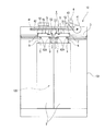
本実施形態に係るエレベータ用ドア装置(以下、単に「ドア装置」とも称する。)は、図1に示すような、建物内を複数の階層に跨って上下方向に延びる昇降路11と、昇降路11内を昇降するかご12と、を備えるエレベータ10において、かご12の出入口120を開閉する。このかご12は、出入口120を有するかご本体121と、かご本体121に配置されて出入口120を開閉するドア装置1と、を有する。
The elevator door device (hereinafter, also simply referred to as “door device”) according to the present embodiment includes a
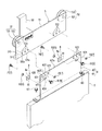
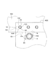
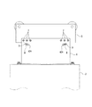
ドア装置1は、図2及び図3にも示すように、かご12の出入口120を開閉するドア2と、出入口120の上方においてドア2を吊り下げた状態で該出入口120の幅方向(図2における左右方向:以下、「開閉方向」とも称する。)に往復動可能なドアハンガー5と、ドア2とドアハンガー5との間に配置されてドア2とドアハンガー5とを接続する接続部材6と、ドアハンガー5と接続部材6とを連結する第一の固定部材(第三固定部材)7と、ドアハンガー5に対する接続部材6の位置ずれを抑えるズレ防止部材8と、ズレ防止部材8を固定する第二の固定部材(第四固定部材)9と、を備える。また、ドア装置1は、ドアハンガー5を案内するガイドレール3と、ドア2を開閉方向に移動させる駆動装置4と、を備える。
As shown in FIGS. 2 and 3, the door device 1 has a
本実施形態のドア装置1は、いわゆるセンターオープン式のドア装置であり、複数(本実施形態の例では、二つ)のドア2と、ドア2の数に対応する数(本実施形態の例では、二つ)のドアハンガー5と、を有する。また、本実施形態のドア装置1において、第一の固定部材7は、第一のボルト(第三ボルト)71と、該第一のボルト71と螺合する第一のナット(第三ナット)72と、を含み、第二の固定部材9は、第二のボルト(第四ボルト)91と、該第二のボルト91と螺合する第二のナット(第四ナット)92と、を含む。本実施形態の第一のボルト71は、例えば、M8ボルト(呼び径が8mmのボルト)である。また、第二のボルト91は、例えば、M10ボルト(呼び径が10mmのボルト)である。
The door device 1 of the present embodiment is a so-called center-open type door device, and has a plurality of (two in the example of the present embodiment)
ガイドレール3は、かご本体121の出入口120の上方において開閉方向に延び、ドアハンガー5を案内する。本実施形態のガイドレール3は、二つのドアハンガー5のそれぞれを案内する。
The guide rail 3 extends in the opening / closing direction above the entrance /
駆動装置4は、かご本体121に配置され、ドアハンガー5を直接又は間接に駆動する。この駆動装置4は、ガイドレール3の上方位置において開閉方向に間隔をあけて配置される一対のプーリー41と、一対のプーリー41に架け渡された無端環状のベルト体42と、一対のプーリー41のうちの一方のプーリー41を回転駆動するモータ43と、を有する。
The drive device 4 is arranged in the
二つのドアハンガー5のそれぞれは、本体51と、本体51に取り付けられてガイドレール3に案内される被ガイド部52と、本体51と駆動装置4のベルト体42とを連結する連結部材53と、を有する。
Each of the two
本体51は、接続部材6との接続位置において該接続部材6が当接するハンガー側当接面(当接面)510を有する。本体51の下端(端部)511aは、直線状に延びてハンガー側当接面510の下端縁(端縁)510aを構成する。本実施形態の本体51では、少なくとも下端511aを含む部位(下端側部位)511が、上下方向及び開閉方向を含む面方向に沿った板状であり、該下端側部位511がその表面にハンガー側当接面510を含んでいる。この本体51の下端511aは、開閉方向に延びている。
The
ハンガー側当接面510には、第一のボルト71が挿通される貫通孔512が形成されている。即ち、本体51は、貫通孔512を有する。本実施形態のハンガー側当接面510は、本体51の下端511aに沿って複数(本実施形態の例では、六つ)の貫通孔512を有する。具体的に、本実施形態のハンガー側当接面510には、開閉方向に間隔をあけて配置される三つの貫通孔512の組が開閉方向の両側のそれぞれに形成されている。これら複数の貫通孔512のそれぞれの内径は、第一のボルト71の呼び径より大きい。即ち、各貫通孔512は、第一のボルト71に対して、いわゆるばか穴である。
A through
被ガイド部52は、いわゆる回転ローラであり、本体51から延びる支軸部521と、支軸部521を回転中心にして回転可能なローラ体522と、を有する。支軸部521は、本体51に固定され、出入口120における乗客の出入り方向に延びる。また、ローラ体522は、外周上に溝を有し、該溝にガイドレール3が嵌まり込む。また、ドアハンガー5は、ガイドレール3を挟んで被ガイド部52と反対側に、ドア2(ドアハンガー5)が上方に移動してガイドレール3から脱落しないための複数のアップスラストローラも有する(不図示)。
The guided
連結部材53の下端部は、本体51に接続され、連結部材53の上端部は、駆動装置4のベルト体42に接続される。二つのドアハンガー5のうちの一方(図2における右側)のドアハンガー5の連結部材53は、一対のプーリー41に架け渡された無端環状のベルト体42における上側に位置する部位に接続される。また、二つのドアハンガー5のうちの他方(図2における左側)のドアハンガー5の連結部材53は、一対のプーリー41に架け渡された無端環状のベルト体42における下側に位置する部位に接続されている。
The lower end of the connecting
接続部材6は、図4にも示すように、ドア2に固定される固定部61と、固定部61から上方に延びる延設部62と、を有する。
As shown in FIG. 4, the connecting
固定部61は、ボルト等の締結部材63によってドア2の上端に固定される(図3参照)。これにより、接続部材6がドア2に対して固定される、即ち、接続部材6とドア2とが接続される。本実施形態の固定部61は、延設部62の下端において、水平面に沿って広がる板状の部位である。
The fixing
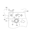
延設部62は、ドアハンガー5(詳しくは、本体51)との接続部位においてハンガー側当接面510と対向した状態で当接する接続部材側当接面(当接面)620を有する。本実施形態の延設部62は、上下方向及び開閉方向を含む面方向に沿った矩形板状の部位である。この延設部62は、上端621aを含む部位(上端側部位)621の表面に接続部材側当接面620を含む。また、延設部62は、上端側部位621の表面に接続部材側当接面620と隣接し且つ該接続部材側当接面620と面一に広がる隣接面622も含む。本実施形態の隣接面622は、接続部材側当接面(ドアハンガー5の本体51におけるハンガー側当接面510と重なる面)620の下側において該接続部材側当接面620と隣接する。
The
接続部材側当接面620には、第一のボルト71が挿通される貫通孔623が形成されている。即ち、延設部62は、貫通孔623を有する。本実施形態の接続部材側当接面620は、延設部62の上端621aに沿ってハンガー側当接面510の貫通孔512の数と対応する数(本実施形態の例では、六つ)の貫通孔623を有する。これら複数の貫通孔623のそれぞれは、接続部材側当接面620において、ハンガー側当接面510の対応する貫通孔512と互いに重なる位置に配置されている。具体的に、本実施形態の接続部材側当接面620には、開閉方向に間隔をあけて配置される三つの貫通孔623の組が開閉方向の両側のそれぞれに形成されている。これら複数の貫通孔623の内径は、ハンガー側当接面510に形成されている貫通孔512の内径と同様に、第一のボルト71の呼び径より大きい。即ち、各貫通孔623は、第一のボルト71に対して、いわゆるばか穴である。
A through
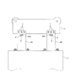
隣接面622、又は該隣接面622と接続部材側当接面620とに跨る位置には、第二のボルト91が挿通される長穴624が形成されている。即ち、延設部62は、隣接面622、又は該隣接面622と接続部材側当接面620とに跨る位置に、第二のボルト91が挿通される長穴624を有する。本実施形態の延設部62は、隣接面622に長穴624を有する。
An
長穴624は、開閉方向に間隔をあけて配置される一対の貫通孔623の下方位置に配置されている。この長穴624は、ズレ防止部材8を貫通した第二のボルト91が挿通された状態において、該ズレ防止部材8の上端8aがドアハンガー5の下端511aに当接する位置に設けられている。また、長穴624は、一対の貫通孔623の下方位置で且つ開閉方向における一対の貫通孔623の中央位置に配置されている。この長穴624の短径(延びている方向と直交する方向の内径)は、第二のボルト91の呼び径より大きい。本実施形態の延設部62では、一対の貫通孔623が、二つ(二対)配置されているため、延設部62は、二つの長穴624を有する。
The
二つの長穴624のそれぞれは、ドアハンガー5(本体51)の下端511aの延びる方向に対して傾斜方向に延びる。二つの長穴624のうちの戸開側(図3の右側)の長穴624は、戸開側に進むにつれて先下がりとなる傾斜方向に延びている。また、二つの長穴624のうちの戸閉側(図3の左側)の長穴624は、戸閉側に進むにつれて先下がりとなる傾斜方向に延びている。即ち、二つの長穴624は、下方に向かうに従って互いの間隔が広くなっている、いわゆる「八」の字状である。ドア2の下端部に力が加わった場合、ドアハンガー5と接続部材6の相対的なずれ方向は、主に回転方向と考えられる。二つの長穴624が「八」の字状に配置されていれば、長穴624の長径方向と、回転方向にかかる力の方向とが、相異することになるため、例えば「逆八」の字状に配置される場合と比較して、ドアハンガー5と接続部材6が相対的にずれ難くなる。
Each of the two
ドアハンガー5の下端511aの延びる方向(本実施形態の例では、開閉方向)に対する各長穴624の延びる方向の角度αは、それぞれ45°未満である(図4参照)。本実施形態の角度αは、例えば、15°である。
The angle α of each
この接続部材6は、複数の貫通孔623とドアハンガー5の複数の貫通孔512とがそれぞれ重なった状態で、接続部材6の貫通孔623と、該貫通孔623に対応するドアハンガー5の貫通孔512とのそれぞれに、第一のボルト71が挿通され、これら挿通された状態の第一のボルト71に第一のナット72がそれぞれ螺合されることによって、ドアハンガー5に固定されている。
The connecting
ズレ防止部材8は、ドアハンガー5の下端511aに当接した状態で第二の固定部材9によって接続部材6に固定されている。このズレ防止部材8では、上端8aが開閉方向に延びている。本実施形態のズレ防止部材8は、板状部材、より詳しくは、矩形の板状部材である。また、ズレ防止部材8は、第二のボルト91が挿通される貫通孔81を有する。
The
このズレ防止部材8は、貫通孔81と接続部材6の長穴624とが重なった状態で該貫通孔81と該長穴624とに第二のボルト91が挿通され、この挿通された状態の第二のボルト91に第二のナット92が螺合されることによって、接続部材6に固定されている。このとき、ズレ防止部材8は、ドアハンガー5の下端511aに対して傾斜方向に延びる長穴624の前記下端511aに近づく側(図3における水平方向の内側)に十分に寄せられた位置において固定されている。
In the
本実施形態の接続部材6では、二つの長穴624のそれぞれと対応する位置にズレ防止部材8が固定されている。即ち、本実施形態のドア装置1では、一つの接続部材6に二つのズレ防止部材8が固定されている。
In the connecting
以上のドア装置1によれば、ズレ防止部材8が長穴624におけるドアハンガー5の下端511aに近づく側に十分に寄せられた状態で接続部材6に固定されていることで、接続部材6とドアハンガー5との各当接面(ハンガー側当接面510、接続部材側当接面620)の貫通孔512、623の周縁部(貫通孔周縁部)5120、6230が、該貫通孔512、623に挿通されている第一のボルト71にそれぞれ当接している(図6参照)。このため、当接面510、620に沿った方向の力がドア2に加わっても、接続部材6がドアハンガー5に対してずれ難い。これにより、ドア2がドアハンガー5に対してずれ難くなる。詳しくは、以下の通りである。
According to the door device 1 described above, the
本実施形態のドア装置1において、ドアハンガー5と接続部材6との各当接面510、620の貫通孔512、623は、組み立て時等において第一のボルト71を挿通し易いように、第一のボルト71の径(呼び径)よりも大きい。このため、互いの貫通孔512、623が重なるようにドアハンガー5と接続部材6とを配置し、第一の固定部材7(第一のボルト71及び第一のナット72)によって連結しただけでは、第一のボルト71と、各当接面510、620の貫通孔周縁部5120、6230との間には、僅かな隙間βがそれぞれ形成される(例えば、図5の符号β参照)。この状態では、各当接面510、620に沿った方向の力がドア2に加わると、前記隙間βの分だけドアハンガー5と接続部材6とがそれぞれずれ易い(各当接面510、620に沿った方向に相対移動し易い)。尚、図5においては、隙間βを誇張して表している。
In the door device 1 of the present embodiment, the through
しかし、本実施形態のドア装置1によれば、ドアハンガー5の下端511aの延びる方向(開閉方向)に対して傾斜方向に延びる長穴624にズレ防止部材8を貫通する第二のボルト91が挿通されているため、ズレ防止部材8が長穴624の前記下端511aに近づく側(図5における右側:矢印γ参照)に十分に寄せられることで、ドアハンガー5の下端511aがズレ防止部材8の上端8aに押されてドアハンガー5と接続部材6とが上下方向に相対移動する。具体的には、接続部材6がドアハンガー5の下端511aに対して下方に移動する。これにより、各当接面510、620の貫通孔周縁部5120、6230が第一のボルト71(詳しくは、第一のボルト71の径方向の反対側の各位置)にそれぞれ当接した状態となる(図6参照)。このため、各当接面510、620に沿った方向の力がドア2に加わっても、接続部材6がドアハンガー5に対してずれ難い(相対移動し難い)。即ち、ドアハンガー5と接続部材6との前記隙間βの分のずれがそれぞれ生じ難い。
However, according to the door device 1 of the present embodiment, the
また、本実施形態のドア装置1では、長穴624の延びる方向の開閉方向(ドアハンガー5の下端511aの延びる方向)に対する角度は、45°未満である。このため、ズレ防止部材8がドアハンガー5の下端511aに押されたときの該ズレ防止部材8に加わる長穴624の延びる方向の力(力の成分)が抑えられ、これにより、ズレ防止部材8がドアハンガー5の下端511aに押されても長穴624の前記下端511aから離れる側(図6における左側)にずれ難い。その結果、各当接面510、520に沿った方向の力がドア2に加わっても各当接面510、620の貫通孔周縁部5120、6230が第一のボルト71にそれぞれ当接した状態(図6参照)が維持され、ドア2がドアハンガー5に対してずれ難い。
Further, in the door device 1 of the present embodiment, the angle of the
尚、本発明のエレベータ用ドア装置は、上記実施形態に限定されるものではなく、本発明の要旨を逸脱しない範囲内において種々変更を加え得ることは勿論である。例えば、ある実施形態の構成に他の実施形態の構成を追加することができ、また、ある実施形態の構成の一部を他の実施形態の構成に置き換えることができる。さらに、ある実施形態の構成の一部を削除することができる。 The elevator door device of the present invention is not limited to the above embodiment, and it goes without saying that various modifications can be made without departing from the gist of the present invention. For example, the configuration of one embodiment can be added to the configuration of another embodiment, and a part of the configuration of one embodiment can be replaced with the configuration of another embodiment. In addition, some of the configurations of certain embodiments can be deleted.
上記実施形態のドア装置1は、かご12に設けられているが、この構成に限定されない。ドア装置1は、エレベータ10の乗場に設けられてもよい。
The door device 1 of the above embodiment is provided in the
上記実施形態のドア装置1では、接続部材6(延設部62)が長穴624を有し、上端8aをドアハンガー5の下端511aに当接させた状態でズレ防止部材8が接続部材6に第二の固定部材9によって固定されているが、この構成に限定されない。例えば、ドアハンガー5が長穴624を有し、下端を接続部材6(延設部62)の上端に当接させた状態でズレ防止部材8がドアハンガー5に第二の固定部材9によって固定される構成でもよい。即ち、ドアハンガー5と接続部材6との接続部位における各構成が相手側の部材にそれぞれ設けられる構成でもよい。
In the door device 1 of the above embodiment, the connecting member 6 (extended portion 62) has an
上記実施形態のドア装置1では、ドア2とドアハンガー5とが接続部材6を介して接続されているが、この構成に限定されない。ドア2とドアハンガー5とが接続されていてもよい。この場合、例えば、接続部材6の延設部62に相当する部位をドア2に設け、該ドア2に当接面620と貫通孔623と長穴624とが設けられ、上端8aをドアハンガー5の下端511aに当接させた状態でズレ防止部材8が第二の固定部材9によってドア2(延設部62に相当する部位)に固定されてもよい。また、ドアハンガー5に長穴624が設けられ、下端をドア2の上端に当接させた状態でズレ防止部材8が第二の固定部材9によってドアハンガー5に固定されてもよい。
In the door device 1 of the above embodiment, the
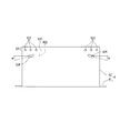
上記実施形態のドア装置1では、二つの長穴が接続部材において「八」の字状に配置されているが、この構成に限定されない。例えば、二つの長穴624が、図7に示すように、各長穴624の延びる方向が同じ(平行)になるように配置されてもよく、図8に示すように、逆「八」の字状に(即ち、上方側ほど互いの間隔が広がるように)配置されてもよい。
In the door device 1 of the above embodiment, two elongated holes are arranged in a "eight" shape in the connecting member, but the present invention is not limited to this configuration. For example, two slotted
また、上記実施形態のドア装置1では、一つの部材(上記実施形態の例では接続部材6であるが、ドアハンガー5やドア2等でもよい。)に設けられる長穴624の数は、二つであるが、この構成に限定されない。一つの部材に設けられる長穴624の数は、一つでもよく、三つ以上でもよい。
Further, in the door device 1 of the above embodiment, the number of
また、上記実施形態のドア装置1では、ドア2とドアハンガー5との間に一つの接続部材6が配置されているが、この構成に限定されない。図9に示すように、ドア2とドアハンガー5との間に複数(図9に示す例では二つ)の接続部材6Aが配置されてもよい。この場合、各接続部材6Aに上記実施形態の接続部位の構成(ドアハンガー5と接続部材6との接続部位の構成:例えば、ズレ防止部材8を貫通した状態の第二のボルト91が長穴624に挿通等されている構成)が採用されてもよく、複数の接続部材6Aのうちの一部の接続部材6Aに上記実施形態の接続部位の構成が採用されてもよい。即ち、複数の接続部材6Aのうちの少なくとも一つに、上記実施形態の接続部位の構成が採用されていればよい。
Further, in the door device 1 of the above embodiment, one connecting
また、上記実施形態のドア装置1では、長穴624は、ドアハンガー5の下端511aの延びる方向に対して傾斜する方向に真っ直ぐに延びているが、この構成に限定されない。例えば、長穴624は、屈曲や湾曲(図10参照)等していてもよい。この場合、長穴624において、ズレ防止部材8が当接する端部(上記実施形態の例では、ドアハンガー5の下端511a)に近い側(図10における右側)の該端部の延びる方向に対する角度が小さい方が、ドア2に各当接面510、620に沿った方向の力が加わったときにズレ防止部材8がずれ難くなるため好ましい。
Further, in the door device 1 of the above embodiment, the
1…エレベータ用ドア装置、2…ドア、3…ガイドレール、4…駆動装置、41…プーリー、42…ベルト体、43…モータ、5…ドアハンガー、51…本体、510…ハンガー側当接面(当接面)、511…下端側部位、511a…下端、512…貫通孔、5120…貫通孔周縁部、52…被ガイド部、521…支軸部、522…ローラ体、53…連結部材、6、6A…接続部材、61…固定部、62…延設部、620…接続部材側当接面(当接面)、621…上端側部位、621a…上端、622…隣接面、623…貫通孔、624…長穴、63…締結部材、7…第一の固定部材(第三固定部材)、71…第一のボルト(第三ボルト)、72…第一のナット(第三ナット)、8…ズレ防止部材、8a…上端、81…貫通孔、9…第二の固定部材(第四固定部材)、91…第二のボルト(第四ボルト)、92…第二のナット(第四ナット)、10…エレベータ、11…昇降路、12…かご、120…出入口、121…かご本体、α…角度、β…隙間
1 ... Elevator door device, 2 ... Door, 3 ... Guide rail, 4 ... Drive device, 41 ... Pulley, 42 ... Belt body, 43 ... Motor, 5 ... Door hanger, 51 ... Main body, 510 ... Hanger side contact surface (Abutment surface) 511 ... Lower
Claims (4)
前記出入口の上方において前記ドアを吊り下げた状態で該出入口の幅方向に往復動可能なドアハンガーと、
第一ボルトと該第一ボルトに螺合する第一ナットとを含み且つ前記ドアと前記ドアハンガーとの接続部位において該ドアと該ドアハンガーとを連結する第一固定部材と、
前記ドアハンガーに対する前記ドアの位置ずれを抑えるズレ防止部材と、
第二ボルトと該第二ボルトに螺合する第二ナットとを含み且つ前記ズレ防止部材を固定する第二固定部材と、を備え、
前記ドアと前記ドアハンガーとは、前記接続部位において互いに対向した状態で当接し、且つ前記第一ボルトが挿通される貫通孔が互いに重なる位置に形成された当接面をそれぞれ有し、
前記ドア及び前記ドアハンガーのうちの一方の部材は、直線状に延びて前記当接面の端縁を構成し且つ前記ズレ防止部材が当接する端部を有し、
前記ドア及び前記ドアハンガーのうちの他方の部材は、前記当接面と隣接し且つ該当接面と面一に広がる隣接面に、前記端部の延びる方向に対して傾斜方向に延びる長穴を有し、
前記ドアと前記ドアハンガーとの当接方向において、前記隣接面と前記ズレ防止部材とが対向した状態で前記第二ボルトが前記長穴に挿通されると共に前記ズレ防止部材を貫通している、エレベータ用ドア装置。 Doors that open and close the entrance and exit of the car or landing,
A door hanger that can reciprocate in the width direction of the doorway while the door is suspended above the doorway.
A first fixing member including a first bolt and a first nut screwed into the first bolt and connecting the door and the door hanger at a connection portion between the door and the door hanger.
A misalignment prevention member that suppresses the misalignment of the door with respect to the door hanger,
A second fixing member including a second bolt and a second nut screwed into the second bolt and fixing the slip prevention member.
The door and the door hanger each have an abutting surface formed at a position where the through holes through which the first bolt is inserted are in contact with each other in a state of facing each other at the connecting portion.
One member of the door and the door hanger extends linearly to form an edge of the contact surface and has an end to which the slip prevention member abuts.
The other member of said door and said door hanger, said contact surface and the adjacent surface adjacent to and extending abutting surface flush with, extended building slot in the inclined direction with respect to the direction of extension of said end portion have a,
In the contact direction between the door and the door hanger, the second bolt is inserted into the elongated hole and penetrates the slip prevention member in a state where the adjacent surface and the slip prevention member face each other . Elevator door device.
前記出入口の上方において前記ドアを吊り下げた状態で該出入口の幅方向に往復動可能なドアハンガーと、
前記ドアと前記ドアハンガーとの間に配置されて該ドアと該ドアハンガーとを接続する接続部材と、
第三ボルトと該第三ボルトに螺合する第三ナットとを含み且つ前記接続部材と前記ドアハンガーとの接続部位において該接続部材と該ドアハンガーとを連結する第三固定部材と、
前記ドアハンガーに対する前記接続部材の位置ずれを抑えるズレ防止部材と、
第四ボルトと該第四ボルトに螺合する第四ナットとを含み且つ前記ズレ防止部材を固定する第四固定部材と、を備え、
前記接続部材と前記ドアハンガーとは、前記接続部位において互いに対向した状態で当接し、且つ前記第三ボルトが挿通される貫通孔が互いに重なる位置に形成された当接面をそれぞれ有し、
前記接続部材及び前記ドアハンガーのうちの一方の部材は、直線状に延びて前記当接面の端縁を構成し且つ前記ズレ防止部材が当接する端部を有し、
前記接続部材及び前記ドアハンガーのうちの他方の部材は、前記当接面と隣接し且つ該当接面と面一に広がる隣接面に、前記端部の延びる方向に対して傾斜方向に延びる長穴を有し、
前記接続部材と前記ドアハンガーとの当接方向において、前記隣接面と前記ズレ防止部材とが対向した状態で前記第四ボルトが前記長穴に挿通されると共に前記ズレ防止部材を貫通している、エレベータ用ドア装置。 Doors that open and close the entrance and exit of the car or landing,
A door hanger that can reciprocate in the width direction of the doorway while the door is suspended above the doorway.
A connecting member arranged between the door and the door hanger and connecting the door and the door hanger,
A third fixing member including a third bolt and a third nut screwed into the third bolt and connecting the connecting member and the door hanger at a connection portion between the connecting member and the door hanger.
A misalignment prevention member that suppresses misalignment of the connection member with respect to the door hanger,
A fourth fixing member including a fourth bolt and a fourth nut screwed into the fourth bolt and fixing the slip prevention member.
The connecting member and the door hanger each have an abutting surface formed at a position where the through holes through which the third bolt is inserted are in contact with each other in a state of facing each other at the connecting portion.
One of the connecting member and the door hanger extends linearly to form an edge of the contact surface and has an end to which the slip prevention member abuts.
The connecting member and the other member of said door hanger, said contact surface and the adjacent surface adjacent to and extending abutting surface flush with, extended building length inclined to the direction of extension of said end portion It has a hole,
In the contact direction between the connecting member and the door hanger, the fourth bolt is inserted into the elongated hole and penetrates the slip prevention member in a state where the adjacent surface and the slip prevention member face each other. , Elevator door device.
Priority Applications (1)
| Application Number | Priority Date | Filing Date | Title |
|---|---|---|---|
| JP2018193605A JP6889868B2 (en) | 2018-10-12 | 2018-10-12 | Elevator door device |
Applications Claiming Priority (1)
| Application Number | Priority Date | Filing Date | Title |
|---|---|---|---|
| JP2018193605A JP6889868B2 (en) | 2018-10-12 | 2018-10-12 | Elevator door device |
Publications (2)
| Publication Number | Publication Date |
|---|---|
| JP2020059597A JP2020059597A (en) | 2020-04-16 |
| JP6889868B2 true JP6889868B2 (en) | 2021-06-18 |
Family
ID=70220717
Family Applications (1)
| Application Number | Title | Priority Date | Filing Date |
|---|---|---|---|
| JP2018193605A Active JP6889868B2 (en) | 2018-10-12 | 2018-10-12 | Elevator door device |
Country Status (1)
| Country | Link |
|---|---|
| JP (1) | JP6889868B2 (en) |
Families Citing this family (1)
| Publication number | Priority date | Publication date | Assignee | Title |
|---|---|---|---|---|
| JP7566203B2 (en) * | 2022-03-14 | 2024-10-11 | 三菱電機株式会社 | Elevator car door device |
Family Cites Families (4)
| Publication number | Priority date | Publication date | Assignee | Title |
|---|---|---|---|---|
| JPS571260U (en) * | 1980-06-02 | 1982-01-06 | ||
| JPS58156861U (en) * | 1982-04-12 | 1983-10-19 | 三菱電機株式会社 | elevator door device |
| JPH08245142A (en) * | 1995-03-09 | 1996-09-24 | Toshiba Corp | Elevator doorway equipment |
| US6845849B2 (en) * | 2003-01-21 | 2005-01-25 | Thyssen Elevator Capital Corp | Height adjustment clip for an elevator door |
-
2018
- 2018-10-12 JP JP2018193605A patent/JP6889868B2/en active Active
Also Published As
| Publication number | Publication date |
|---|---|
| JP2020059597A (en) | 2020-04-16 |
Similar Documents
| Publication | Publication Date | Title |
|---|---|---|
| JPWO2008114344A1 (en) | Elevator doorway equipment | |
| JP6889868B2 (en) | Elevator door device | |
| KR100829964B1 (en) | Deflection structure of sliding swing door | |
| KR102473813B1 (en) | Two way interlocking sliding door rail gate structure for safety | |
| JP6827653B1 (en) | Elevator door device | |
| JP2011148623A (en) | Elevator door | |
| RU2437823C2 (en) | Elevator door | |
| WO2012008043A1 (en) | Elevator door assembly | |
| JP2012218897A (en) | Elevator | |
| KR101774542B1 (en) | Sliding door unit | |
| JP2020059598A (en) | Door device for elevator | |
| JP2013001482A (en) | Door device for elevator, and sill groove blocking device for elevator | |
| JP6001141B1 (en) | Elevator hall door device | |
| JPH08143256A (en) | Elevator | |
| JP2012066914A (en) | Fixture for regulating movement of door for elevator | |
| JP5285456B2 (en) | Door device | |
| JP2016210563A (en) | Door opening travel preventing device for elevator | |
| CN109562918B (en) | elevator door device | |
| CN101068743A (en) | Door device for elevator | |
| KR20110038878A (en) | Clutch assembly for elevator door opening and closing | |
| JP2011144007A (en) | Door device of elevator | |
| EP1467052B1 (en) | Guide system | |
| JPWO2012150624A1 (en) | Elevator door opening and closing device | |
| JP5319712B2 (en) | Elevator door opening prevention device | |
| JP4614720B2 (en) | Elevator hall |
Legal Events
| Date | Code | Title | Description |
|---|---|---|---|
| A621 | Written request for application examination |
Free format text: JAPANESE INTERMEDIATE CODE: A621 Effective date: 20191126 |
|
| A977 | Report on retrieval |
Free format text: JAPANESE INTERMEDIATE CODE: A971007 Effective date: 20200929 |
|
| A131 | Notification of reasons for refusal |
Free format text: JAPANESE INTERMEDIATE CODE: A131 Effective date: 20201030 |
|
| A521 | Request for written amendment filed |
Free format text: JAPANESE INTERMEDIATE CODE: A523 Effective date: 20201106 |
|
| TRDD | Decision of grant or rejection written | ||
| A01 | Written decision to grant a patent or to grant a registration (utility model) |
Free format text: JAPANESE INTERMEDIATE CODE: A01 Effective date: 20210423 |
|
| A61 | First payment of annual fees (during grant procedure) |
Free format text: JAPANESE INTERMEDIATE CODE: A61 Effective date: 20210506 |
|
| R150 | Certificate of patent or registration of utility model |
Ref document number: 6889868 Country of ref document: JP Free format text: JAPANESE INTERMEDIATE CODE: R150 |
|
| R250 | Receipt of annual fees |
Free format text: JAPANESE INTERMEDIATE CODE: R250 |
|
| R250 | Receipt of annual fees |
Free format text: JAPANESE INTERMEDIATE CODE: R250 |