JP6889864B2 - クローラ取付機構 - Google Patents
クローラ取付機構 Download PDFInfo
- Publication number
- JP6889864B2 JP6889864B2 JP2017179181A JP2017179181A JP6889864B2 JP 6889864 B2 JP6889864 B2 JP 6889864B2 JP 2017179181 A JP2017179181 A JP 2017179181A JP 2017179181 A JP2017179181 A JP 2017179181A JP 6889864 B2 JP6889864 B2 JP 6889864B2
- Authority
- JP
- Japan
- Prior art keywords
- drive wheel
- mounting
- crawler
- wheel
- centering jig
- Prior art date
- Legal status (The legal status is an assumption and is not a legal conclusion. Google has not performed a legal analysis and makes no representation as to the accuracy of the status listed.)
- Active
Links
- 230000004323 axial length Effects 0.000 claims description 14
- 230000002093 peripheral effect Effects 0.000 claims description 12
- 238000003780 insertion Methods 0.000 description 5
- 230000037431 insertion Effects 0.000 description 5
- 238000010586 diagram Methods 0.000 description 2
- 238000005096 rolling process Methods 0.000 description 2
- 125000006850 spacer group Chemical group 0.000 description 2
- 229910000831 Steel Inorganic materials 0.000 description 1
- 239000000463 material Substances 0.000 description 1
- 238000000034 method Methods 0.000 description 1
- NJPPVKZQTLUDBO-UHFFFAOYSA-N novaluron Chemical compound C1=C(Cl)C(OC(F)(F)C(OC(F)(F)F)F)=CC=C1NC(=O)NC(=O)C1=C(F)C=CC=C1F NJPPVKZQTLUDBO-UHFFFAOYSA-N 0.000 description 1
- 239000010959 steel Substances 0.000 description 1
- 238000003466 welding Methods 0.000 description 1
Images
Landscapes
- Automobile Manufacture Line, Endless Track Vehicle, Trailer (AREA)
Description
Claims (3)
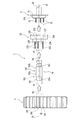
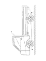
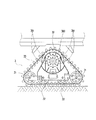
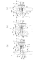
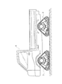
- 回転軸心回りに回転可能な駆動輪と、回転軸心回りに回転可能な従動輪と、前記駆動輪および従動輪に巻掛けられる無端状の履帯とを備えたクローラを、車両のハブホイールに取付けるためのクローラ取付機構であって、
軸心方向一方側が前記ハブホイールに取付けられた状態で軸心方向他方側に前記駆動輪が取付けられる駆動輪取付体と、
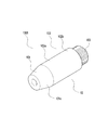
該駆動輪取付体に装着された状態で前記駆動輪のボス孔に挿通可能な芯出し治具とを備え、
前記駆動輪取付体は、前記駆動輪に形成されたボルト孔に挿通する取付ボルトを備え、該取付ボルトは、前記駆動輪取付体の回転軸心に沿い、且つ該回転軸心の周囲周方向に間隔をおいて複数本設けられ、
前記芯出し治具は、前記駆動輪取付体の軸心方向に沿う軸状に形成され、その基端部が前記駆動輪取付体の回転軸心上で、且つ前記駆動輪取付体の軸心方向他方側に取付けられ、該芯出し治具の軸方向長さは、前記駆動輪取付体に対する前記取付ボルトの突出量を超えるよう設定されたことを特徴とするクローラ取付機構。 - 前記芯出し治具の先端側であって前記取付ボルトに対して突出した前記芯出し治具の突出部分の外周面は、先端に向けて小径となる傾斜面とされ、前記芯出し治具の、前記先端側に対する基端側の外周面は、軸心方向に亘って前記ボス孔と略同一径とされた請求項1に記載のクローラ取付機構。
- 前記駆動輪取付体は、軸心方向他方側の中心部に軸心方向外方に向かって突設され前記ボス孔に挿入される環状のボス部を有し、該ボス部の外径は、前記芯出し治具の基端側の外径と略同一に設定された請求項1または請求項2に記載のクローラ取付機構。
Priority Applications (1)
| Application Number | Priority Date | Filing Date | Title |
|---|---|---|---|
| JP2017179181A JP6889864B2 (ja) | 2017-09-19 | 2017-09-19 | クローラ取付機構 |
Applications Claiming Priority (1)
| Application Number | Priority Date | Filing Date | Title |
|---|---|---|---|
| JP2017179181A JP6889864B2 (ja) | 2017-09-19 | 2017-09-19 | クローラ取付機構 |
Publications (2)
| Publication Number | Publication Date |
|---|---|
| JP2019051913A JP2019051913A (ja) | 2019-04-04 |
| JP6889864B2 true JP6889864B2 (ja) | 2021-06-18 |
Family
ID=66014118
Family Applications (1)
| Application Number | Title | Priority Date | Filing Date |
|---|---|---|---|
| JP2017179181A Active JP6889864B2 (ja) | 2017-09-19 | 2017-09-19 | クローラ取付機構 |
Country Status (1)
| Country | Link |
|---|---|
| JP (1) | JP6889864B2 (ja) |
-
2017
- 2017-09-19 JP JP2017179181A patent/JP6889864B2/ja active Active
Also Published As
| Publication number | Publication date |
|---|---|
| JP2019051913A (ja) | 2019-04-04 |
Similar Documents
| Publication | Publication Date | Title |
|---|---|---|
| US9676231B2 (en) | Aircraft wheel rim with removable flange | |
| JPH09202107A (ja) | 自転車用ハブ | |
| US11511818B2 (en) | Track drive | |
| US20120228926A1 (en) | Track assembly wheel | |
| US9915290B2 (en) | Tool attachment for power-driven winding of winch straps | |
| JP2004523707A (ja) | 自動車両用ハブ/軸受アセンブリの取付け方法 | |
| US20190232716A1 (en) | Systems and methods for attaching a plate to a vehicle | |
| US9044999B2 (en) | Method and apparatus for mounting and demounting large wheels | |
| US9272571B2 (en) | Drive wheel assembly for self-propelled irrigation system | |
| US20160023513A1 (en) | Trailer axle repair kit having spare spindle and flange axle assembly | |
| JP2019051913A (ja) | クローラ取付機構 | |
| EP0991870B1 (en) | Adjustable bearing spacer | |
| JP7178958B2 (ja) | トラックフレーム着脱用治具 | |
| KR101543957B1 (ko) | 휠 교체형 궤도차 차륜 | |
| US9662933B2 (en) | Quick change wheel assembly for a machine | |
| CN222806947U (zh) | 一种用于凸轮盘轴承的拆装工装 | |
| US9757981B2 (en) | Broken axle recovery apparatus | |
| KR20090064623A (ko) | 무한궤도용 분리형 휠 및 무한궤도 탈부착 방법 | |
| US9211949B2 (en) | Aircraft wheel with a universal drive dog | |
| JP3903156B2 (ja) | ハブユニット | |
| KR20170029616A (ko) | 차량 구속 장치 | |
| CN106312399B (zh) | 一种自动焊接车的焊接导轨夹持装置 | |
| CN206122970U (zh) | 一种自动焊接车的焊接导轨夹持装置 | |
| JPS6325922Y2 (ja) | ||
| CN214729200U (zh) | 一种履带链装配件 |
Legal Events
| Date | Code | Title | Description |
|---|---|---|---|
| A621 | Written request for application examination |
Free format text: JAPANESE INTERMEDIATE CODE: A621 Effective date: 20200702 |
|
| A977 | Report on retrieval |
Free format text: JAPANESE INTERMEDIATE CODE: A971007 Effective date: 20210419 |
|
| TRDD | Decision of grant or rejection written | ||
| A01 | Written decision to grant a patent or to grant a registration (utility model) |
Free format text: JAPANESE INTERMEDIATE CODE: A01 Effective date: 20210423 |
|
| A61 | First payment of annual fees (during grant procedure) |
Free format text: JAPANESE INTERMEDIATE CODE: A61 Effective date: 20210506 |
|
| R150 | Certificate of patent or registration of utility model |
Ref document number: 6889864 Country of ref document: JP Free format text: JAPANESE INTERMEDIATE CODE: R150 |