JP6889864B2 - Crawler mounting mechanism - Google Patents
Crawler mounting mechanism Download PDFInfo
- Publication number
- JP6889864B2 JP6889864B2 JP2017179181A JP2017179181A JP6889864B2 JP 6889864 B2 JP6889864 B2 JP 6889864B2 JP 2017179181 A JP2017179181 A JP 2017179181A JP 2017179181 A JP2017179181 A JP 2017179181A JP 6889864 B2 JP6889864 B2 JP 6889864B2
- Authority
- JP
- Japan
- Prior art keywords
- drive wheel
- mounting
- crawler
- wheel
- centering jig
- Prior art date
- Legal status (The legal status is an assumption and is not a legal conclusion. Google has not performed a legal analysis and makes no representation as to the accuracy of the status listed.)
- Active
Links
- 230000004323 axial length Effects 0.000 claims description 14
- 230000002093 peripheral effect Effects 0.000 claims description 12
- 238000003780 insertion Methods 0.000 description 5
- 230000037431 insertion Effects 0.000 description 5
- 238000010586 diagram Methods 0.000 description 2
- 238000005096 rolling process Methods 0.000 description 2
- 125000006850 spacer group Chemical group 0.000 description 2
- 229910000831 Steel Inorganic materials 0.000 description 1
- 239000000463 material Substances 0.000 description 1
- 238000000034 method Methods 0.000 description 1
- NJPPVKZQTLUDBO-UHFFFAOYSA-N novaluron Chemical compound C1=C(Cl)C(OC(F)(F)C(OC(F)(F)F)F)=CC=C1NC(=O)NC(=O)C1=C(F)C=CC=C1F NJPPVKZQTLUDBO-UHFFFAOYSA-N 0.000 description 1
- 239000010959 steel Substances 0.000 description 1
- 238000003466 welding Methods 0.000 description 1
Images
Landscapes
- Automobile Manufacture Line, Endless Track Vehicle, Trailer (AREA)
Description
本発明は、車両の駆動輪をクローラに交換するためのクローラ取付機構に関する。 The present invention relates to a crawler mounting mechanism for replacing a vehicle drive wheel with a crawler.
例えば、作業者や作業具を作業現場まで運搬するのに一般車両が用いられる場合、滑り易い雪道や険しい山道を走行可能とするために、予め作業者により車両の駆動輪がクローラに交換される場合がある。クローラは下記特許文献1に示すように、車両の駆動軸に取付けられる駆動輪と、転輪(従動輪)と、駆動輪および転輪に巻掛けられる無端状の履帯とを備える。 For example, when a general vehicle is used to transport a worker or work tool to a work site, the drive wheel of the vehicle is replaced with a crawler in advance by the worker in order to enable traveling on slippery snowy roads or steep mountain roads. May occur. As shown in Patent Document 1 below, the crawler includes a drive wheel attached to a drive shaft of a vehicle, a rolling wheel (driven wheel), and an endless track wrapped around the driving wheel and the rolling wheel.
ところで、下記特許文献2に、航空機におけるホイール交換機が記載されている。特許文献2のホイール交換機は、交換しようとするホイール組立品を吊持し、所定の方向へ移動させる装置である。すなわちこのホイール交換機は、航空機の脚柱をジャッキによりジャッキアップさせた状態で、車軸に設けられた砲弾型の補助機具とホイール組立品のハブの中心に設けられたインナーレースとを位置合わせしたうえで、ホイール組立品を車軸に取付けるよう移動させる。
By the way, the following
しかしながら、一般車両を滑り易い雪道や険しい山道を走行可能とすべく車両の駆動輪をクローラに交換するのに、上記特許文献2に記載されているような、空港やドックにおいて用いられる大がかりなホイール交換機を準備することは、実質的に不可能である。
However, it is a large-scale use at airports and docks as described in
そこで本発明は、特別な交換機等を用いることなく、車両の駆動輪を容易にクローラに交換し得るクローラ取付機構の提供を目的とする。 Therefore, an object of the present invention is to provide a crawler mounting mechanism capable of easily exchanging a driving wheel of a vehicle with a crawler without using a special exchange or the like.
本発明のクローラ取付機構は、回転軸心回りに回転可能な駆動輪と、回転軸心回りに回転可能な従動輪と、前記駆動輪および従動輪に巻掛けられる無端状の履帯とを備えたクローラを、車両のハブホイールに取付けるためのクローラ取付機構であって、軸心方向一方側が前記ハブホイールに取付けられた状態で軸心方向他方側に前記駆動輪が取付けられる駆動輪取付体と、該駆動輪取付体に装着された状態で前記駆動輪のボス孔に挿通可能な芯出し治具とを備え、前記駆動輪取付体は、前記駆動輪に形成されたボルト孔に挿通する取付ボルトを備え、該取付ボルトは、前記駆動輪取付体の回転軸心に沿い、且つ該回転軸心の周囲周方向に間隔をおいて複数本設けられ、前記芯出し治具は、前記駆動輪取付体の軸心方向に沿う軸状に形成され、その基端部が前記駆動輪取付体の回転軸心上で、且つ前記駆動輪取付体の軸心方向他方側に取付けられ、該芯出し治具の軸方向長さは、前記駆動輪取付体に対する前記取付ボルトの突出量を超えるよう設定されたことを特徴とする。 The crawler mounting mechanism of the present invention includes a drive wheel that can rotate around the center of the rotating shaft, a driven wheel that can rotate around the center of the rotating shaft, and an endless cuff band that is wound around the drive wheel and the driven wheel. A drive wheel mounting mechanism for mounting a crawler on a hub wheel of a vehicle, wherein the drive wheel is mounted on the other side in the axial direction while one side in the axial direction is mounted on the hub wheel. A centering jig that can be inserted into the boss hole of the drive wheel while mounted on the drive wheel mounting body is provided, and the drive wheel mounting body is a mounting bolt that is inserted into a bolt hole formed in the drive wheel. A plurality of mounting bolts are provided along the rotation axis of the drive wheel mounting body and at intervals in the circumferential direction around the rotation axis, and the centering jig is used for mounting the drive wheel. It is formed in an axial shape along the axial direction of the body, and its base end is attached on the rotation axis of the drive wheel mount and on the other side of the drive wheel mount in the axial direction. The axial length of the tool is set so as to exceed the protrusion amount of the mounting bolt with respect to the drive wheel mounting body.
上記構成を備えた本発明のクローラ取付機構によれば、作業者が、車両の駆動輪をハブホイールから取外した後、該ハブホイールに駆動輪取付体の一方側を取付けるとともに、該駆動輪取付体の他方側に芯出し治具を取付ける。芯出し治具の軸方向長さは、駆動輪取付体の回転軸心の周囲周方向に間隔をおいて複数本設けられた取付ボルトの駆動輪取付体に対する突出量を超えるよう設定されているため、この芯出し治具の突出部分をクローラ取付時のガイドとして利用できる。具体的に、クローラの駆動輪のボス孔の周壁面を摺らせるようにして駆動輪を芯出し治具の軸心方向に沿って軸心方向一方側に移動させれば、芯出し治具がボス孔に嵌合され、取付ボルトがクローラのボルト孔に嵌合され、クローラのうちの駆動輪が車両のハブホイールに対して容易に取付けられる。 According to the crawler mounting mechanism of the present invention having the above configuration, after the operator removes the drive wheel of the vehicle from the hub wheel, one side of the drive wheel mounting body is mounted on the hub wheel, and the driving wheel mounting is performed. Attach the centering jig to the other side of the body. The axial length of the centering jig is set so as to exceed the amount of protrusion of a plurality of mounting bolts provided at intervals in the circumferential direction around the rotation axis of the drive wheel mount with respect to the drive wheel mount. Therefore, the protruding portion of the centering jig can be used as a guide when mounting the crawler. Specifically, if the drive wheel is moved to one side in the axial direction along the axial direction of the centering jig by sliding the peripheral wall surface of the boss hole of the drive wheel of the crawler, the centering jig Is fitted into the boss hole, the mounting bolt is fitted into the bolt hole of the crawler, and the drive wheels of the crawler are easily mounted on the hub wheel of the vehicle.
本発明のクローラ取付機構では、前記芯出し治具の先端側であって前記取付ボルトに対して突出した芯出し治具の突出部分の外周面は、先端に向けて小径となる傾斜面とされ、前記芯出し治具の、前記先端側に対する基端側の外周面は、軸心方向に亘って前記ボス孔と略同一径とされた構成を採用することができる。 In the crawler mounting mechanism of the present invention, the outer peripheral surface of the protruding portion of the centering jig that is on the tip end side of the centering jig and protrudes with respect to the mounting bolt is an inclined surface having a small diameter toward the tip. The outer peripheral surface of the centering jig on the base end side with respect to the tip end side may have a structure having substantially the same diameter as the boss hole in the axial direction.
上記構成のクローラ取付機構によれば、作業者が、クローラの駆動輪のボス孔の周壁面を、芯出し治具の先端側に傾斜面に摺らせるようにして、駆動輪を芯出し治具の軸心方向に沿うよう移動させて芯出し治具の基端側まで移動させると、基端側は軸心方向に亘ってボス孔と略同一径であるから、駆動輪を芯出し治具回りに回動させるだけで、取付ボルトに対するボルト孔の位置合わせを行える。 According to the crawler mounting mechanism having the above configuration, the operator slides the peripheral wall surface of the boss hole of the drive wheel of the crawler on the inclined surface toward the tip side of the centering jig to center the drive wheel. When the tool is moved along the axial direction and moved to the base end side of the centering jig, the base end side has substantially the same diameter as the boss hole over the axis direction, so the drive wheel is centered and cured. The bolt holes can be aligned with the mounting bolts simply by rotating them around the jig.
本発明のクローラ取付機構では、前記駆動輪取付体は、軸心方向他方側の中心部に軸心方向外方に向かって突設され前記ボス孔に挿入される環状のボス部を有し、該ボス部の外径は、前記芯出し治具の基端側の外径と略同一に設定された構成を採用することができる。 In the crawler mounting mechanism of the present invention, the drive wheel mounting body has an annular boss portion that protrudes outward in the axial direction from the center portion on the other side in the axial direction and is inserted into the boss hole. It is possible to adopt a configuration in which the outer diameter of the boss portion is set to be substantially the same as the outer diameter on the base end side of the centering jig.
上記構成を備えたクローラ取付機構は、ハブホイールに駆動輪を装着した後、ハブホイールから芯出し治具を取外しても、駆動輪取付体の環状のボスを駆動輪のボス孔に挿入しているため、ハブホイールの回転中心と駆動輪の回転中心とを位置ずれさせることがない。 The crawler mounting mechanism having the above configuration inserts the annular boss of the drive wheel mount into the boss hole of the drive wheel even if the centering jig is removed from the hub wheel after mounting the drive wheel on the hub wheel. Therefore, the center of rotation of the hub wheel and the center of rotation of the drive wheels are not misaligned.
本発明のクローラ取付機構によれば、特別な交換機等を用いることなく、車両の駆動輪を容易にクローラに交換することができる。 According to the crawler mounting mechanism of the present invention, the drive wheels of the vehicle can be easily replaced with crawlers without using a special exchange or the like.
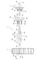
以下、本発明の一実施形態に係るクローラ取付機構を、図面を参照しつつ説明する。図1に示すように、本実施形態に係るクローラ取付機構1は、車両のハブユニット2にクローラ3を装着する際に使用される。このため、説明の便宜上、はじめに車両のハブユニット2およびクローラ3についてその概略を説明する。
Hereinafter, the crawler mounting mechanism according to the embodiment of the present invention will be described with reference to the drawings. As shown in FIG. 1, the crawler mounting mechanism 1 according to the present embodiment is used when the
車両のハブユニット2は、図1に示すように、車軸20に取付けられるハブホイール21と、ハブホイール21の中心周りに、周方向に間隔を置いて配置されたタイヤホイール(図示せず)を取付けるための複数のハブボルト22と、ハブホイール21の一面に取付けられた後述のクローラ3の駆動輪30を取付けるための駆動輪取付体(スペーサとも称する)23とを備える。
As shown in FIG. 1, the
ハブホイール21は、ハブボルト22を固定するためのフランジ部210を備えている。ハブボルト22は、本実施形態では、ハブホイール21の中心周りに、周方向に等間隔に5本配置されている。
The
駆動輪取付体23は、円板状に形成された本体23aと、本体23aの前面中心部(軸心方向他方側の中心)に突設された環状のボス部230とを備えている。本体23aは、軸心方向一方側がハブホイール21に取付けられる。本体23aには、ボス部230の中心周りに、各ハブボルト22が挿通される挿通孔231が形成されている。挿通孔231と挿通孔231との間には、クローラ3を取付けるための取付ボルト233が5本配置されている。各取付ボルト233は、本体23aに対し溶接によって固着されたボルト、または本体23aに対し着脱可能に取付けられたボルトである。取付ボルト233は、駆動輪取付体の回転軸心に沿い、且つ該回転軸心の周囲周方向に間隔を置いて複数設けられ、後述のクローラ3の駆動輪30のボルト孔301に挿入される。本体23aの後面には、フランジ部210が嵌合される凹部232が形成されている。ボス部230の中心には、後述する芯出し治具10を挿入させる挿入孔234が形成され、その内面には、芯出し治具10を接続するための雌ねじが形成されている。
The drive
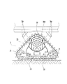
クローラ3は、図3および図5(a)に示すように、回転軸線O2に沿って形成されたボス孔300、および該ボス孔300周りの周方向に等間隔に形成されたボルト孔301を有する駆動輪30と、該駆動輪30の下方に位置ずれして配置された一対の従動輪31,31と、一対の従動輪31,31の間に配置された複数の補助輪32と、無端状の履帯33とを備え、履帯33は、駆動輪30、一対の従動輪31,31、各補助輪32に巻掛けられている。履帯33は、駆動輪30、一対の従動輪31,31、各補助輪32に巻掛けられて三角形状となっている。本実施形態では、三角クローラを使用する。
As shown in FIGS. 3 and 5A, the
本実施形態では、ボルト孔301は、10個形成されているが、駆動輪取付体23の取付ボルト233の本数(5本)に合わせて、10個のうち5個を使用する。使用する5個のボルト孔301の間隔は、取付ボルト233の間隔と同一である。
In the present embodiment, 10
図1に示すように、本発明のクローラ取付機構1は、前述の駆動輪取付体23と、取付ボルト233と、芯出し治具10とを備える。
As shown in FIG. 1, the crawler mounting mechanism 1 of the present invention includes the above-mentioned drive
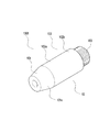
図1および図4に示すように、芯出し治具10は、駆動輪取付体23の軸心方向に沿う軸状に形成された本体部100と、該本体部100の軸線の延長線上に、該軸線に沿うように延出された接続部103とを備える。図5(a)に示すように、芯出し治具10は、鋼材により中空の軸状に形成されている。芯出し治具10の軸方向の長さは、本体部100の軸方向の長さと接続部103の軸方向の長さとを加えた長さL1で、駆動輪取付体23に対する取付ボルト233の突出量L2を超えて突出する長さに設定されている。
As shown in FIGS. 1 and 4, the
本体部100は、ハブホイール21においてその回転軸線O1に沿って取付けられる。本体部100は、円錐台状に形成された先端側部101と、円柱状に形成された基端側部102とを備える。図1に示すように、基端側部102の外周面は、軸心方向に亘って駆動輪30のボス孔300と略同一径とされ、且つ駆動輪取付体23のボス部230の外周面と略同一径とされている。
The
先端側部101は、芯出し治具10をハブホイール21に取付けた状態において、取付ボルト233に対して突出する突出部分である。先端側部101の外周面は、先端に向けて小径となる傾斜面(テーパー面)101aとされる。先端側部101の最小径部101bの径は、駆動輪30のボス孔300の径R2よりも小さく設定され、先端側部101の軸方向の長さは、後述の基端側部102の前部102aの軸方向の長さよりも短く設定されている。先端側部101は、駆動輪30を基端側部102の前部102aにスムーズに移動できるよう構成されている。
The
基端側部102は、先端側部101に連設される前部102aと、該前部102aに連設される後部102bとを備える。前部102aの軸方向の長さL4は、図5(a)に示すように、駆動輪30のボス孔300の軸方向の長さと略同じに設定されている。この長さL4は、本体部100の軸方向の長さと接続部103の軸方向の長さとを加えた長さL1から、取付ボルト233の突出量L2と、先端側部101の軸方向の長さL3とを差引いた長さに設定されている。
The base
基端側部102の後部102bは、図5(c)に示すように、取付ボルト233の突出量と同じ軸方向の長さL2を有している。この軸方向の長さL2は、駆動輪取付体23のボス部230を駆動輪30のボス孔300に挿入し、取付ボルト233をボルト孔301に嵌合させることができる長さとなっている。
As shown in FIG. 5C, the
接続部103は、図1および図3に示すように、本体部100の基端部の端面に軸線方向に沿って突設された環状体であり、該環状体は、本体部100の外径R1よりも小径で、その外周面には、ねじ溝が形成されて雄ねじ103aとなっている。該雄ねじ103aは、駆動輪取付体23のボス部230に螺合する。
As shown in FIGS. 1 and 3, the connecting
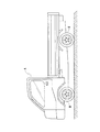
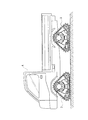
上記構成を備えたクローラ取付機構1を用いて車両の駆動輪をクローラに交換する方法について説明する。まず、作業者は、図示しないジャッキを用いて、図2に示す車両Aをジャッキアップさせ、ハブホイール21から車両Aの駆動輪Bを取外す。この際、駆動輪取付体23は、ハブホイール21に取付けた状態にしておく。
A method of exchanging a driving wheel of a vehicle with a crawler by using the crawler mounting mechanism 1 having the above configuration will be described. First, the operator jacks up the vehicle A shown in FIG. 2 using a jack (not shown), and removes the drive wheel B of the vehicle A from the
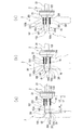
つぎに、作業者は、図5(a)に示すように、駆動輪取付体23のボス部230に芯出し治具10の接続部103を螺合させて取付ける。このようにすると、芯出し治具10の基端側部102は、駆動輪取付体23の軸心方向他方側に、駆動輪取付体23の回転軸心上に取り付けられる。駆動輪取付体23の回転軸線とハブホイール21の回転軸線O1とが同一直線上にあるので、芯出し治具10の軸線は、ハブホイール21の回転軸線O1と同一線上に位置するとともに、取付ボルト233の軸線に対し平行に位置する。
Next, as shown in FIG. 5A, the operator screwes the connecting
つぎに、作業者は、駆動輪取付体23に芯出し治具10を装着した状態で、芯出し治具10の突出した部分にクローラ3の駆動輪30のボス孔300に挿通する。具体的に、作業者は、図5(a)に示すように、複数人でクローラ3を持上げて、持上げたクローラ3の駆動輪30のボス孔300の開口周縁部の内壁面の上側部を、芯出し治具10の先端側部101の傾斜面101aの上側部に預ける。
Next, the operator inserts the centering
つぎに、作業者は、図5(b)に示すように、複数人でクローラ3の駆動輪30のボス孔300の開口周縁部の内壁面の上側部を傾斜面101aの上側部に摺らせるようにして、駆動輪30を芯出し治具10の軸線方向に沿ってハブホイール21側に移動させ、芯出し治具10の基端側部102の前部102a上に位置させる。
Next, as shown in FIG. 5B, a plurality of workers slide the upper portion of the inner wall surface of the opening peripheral portion of the
つぎに、作業者は、芯出し治具10の基端側部102の前部102a上で、ハブホイール21と駆動輪30とを対向させる。この際、ハブホイール21の回転軸線O1と芯出し治具10の軸線とが同一直線上に位置することから、ハブホイール21の回転軸線O1とクローラ3の駆動輪30の回転軸線O2とが同一直線上に位置し、駆動輪30の各ボルト孔301と、各取付ボルト233とが同一径の円周上に位置する。
Next, the operator makes the
つぎに、作業者は、芯出し治具10の基端側部102の前部102a上で、クローラ3の履帯33を把持し履帯33を介して駆動輪30を回転させ、駆動輪30の各ボルト孔301と、各取付ボルト233との位置合わせを行う。作業者は、芯出し治具10回りに駆動輪30を回動させるだけで、取付ボルト233に対するボルト孔301の位置合わせが容易に行える。
Next, the operator grips the
取付ボルト233とボルト孔301との位置合わせ作業終了後、作業者は、図5(c)に示すように、芯出し治具10の軸心方向に沿ってクローラ3の駆動輪30を、芯出し治具10の基端部側(ハブホイール21側)の後部102bに移動させ、取付ボルト233をボルト孔301に挿入させるとともに、駆動輪取付体23の環状のボス部230を駆動輪30のボス孔300に嵌合させる。この際、芯出し治具10の基端側部102の外径R1とボス孔300の径R2とが略同一径であるから、駆動輪30をハブホイール21側にスムーズに移動させることができる。
After completing the alignment work between the mounting
つぎに、作業者は、対角に位置する取付ボルト233の先端部にナットを順次螺合させて締め付け、ハブホイール21に駆動輪30を取付ける。具体的に、駆動輪30とハブホイール21との間に駆動輪取付体23を挟持し、駆動輪30の内面を、駆動輪取付体23の外面に外嵌して取付ける。
Next, the operator sequentially screws and tightens nuts at the tips of the mounting
ハブホイール21に駆動輪30を取付けた後、作業者は、芯出し治具10を回転させ、駆動輪取付体23のボス部230の雌ねじから、芯出し治具10の接続部103の雄ねじを取外し、駆動輪30のボス孔300から芯出し治具10を取外す。この際、駆動輪取付体23のボス部230が駆動輪30のボス孔300に挿入されているため、ハブホイール21の回転軸線O1と駆動輪30の回転軸線O2とが位置ずれすることがない。
After attaching the
このように、本実施形態では、大がかりなホイール交換機を準備することなく、ハブホイール21にクローラ3の駆動輪30を容易に取付けることができる。すなわち、駆動輪取付体23のボス部230に、ハブホイール21に対して取付ボルト233の突出量L2を超えるよう突出する軸状の芯出し治具10を取付け、芯出し治具10上においてクローラ3の駆動輪30の回転軸線O2と、車両Aのハブホイール21の回転軸線O1との芯出し作業を行えるようにしたので、車両Aの駆動輪Bを容易にクローラ3に交換することができる。
As described above, in the present embodiment, the
本発明のクローラ取付機構1は、上記実施形態に限定されない。上記実施形態では、三角クローラの駆動輪30をハブホイール21に装着する場合を例示した。しかしながら、クローラ取付機構1は、駆動輪30および従動輪31を横一列に配置したクローラにも適用することが考えられる。
The crawler mounting mechanism 1 of the present invention is not limited to the above embodiment. In the above embodiment, the case where the
上記実施形態では、芯出し治具10の先端側を円錐台状とする場合を例示した。しかしながら、芯出し治具10は、全体を円柱状に形成することが考えられる。この場合、クローラ3の駆動輪30のボス孔300に、芯出し治具10が挿入できるように、目視によって位置合わせし、クローラ3の駆動輪30をハブホイール21側に軸方向に沿って移動させ、クローラ3の駆動輪30のボス孔300に、駆動輪取付体23のボス部230を挿入し、クローラ3のボルト孔301に取付ボルト233を嵌合させる。
In the above embodiment, a case where the tip side of the centering
上記各実施形態では、車両の駆動形式は具体的に例示しなかった。しかしながら、クローラ取付機構1は、4輪駆動、前輪駆動のいずれにも適用することが考えられる。特に図6に示すように、前後左右の4輪をクローラ3に交換する場合、作業に要する時間を大幅に短縮できる。
In each of the above embodiments, the drive type of the vehicle is not specifically exemplified. However, it is conceivable that the crawler mounting mechanism 1 can be applied to both four-wheel drive and front-wheel drive. In particular, as shown in FIG. 6, when the front, rear, left and right four wheels are replaced with
1…クローラ取付機構、10…芯出し治具、100…本体部、101…先端側部、101a…傾斜面、102…基端側部、102a…前部、102b…後部、103…接続部、2…ハブユニット、20…車軸、21…ハブホイール、22…ハブボルト、23…駆動輪取付体(スペーサ)、230…ボス部、231…挿通孔、233…取付ボルト、3…クローラ、30…駆動輪、300…ボス孔、301…ボルト孔、31…従動輪、32…補助輪、33…履帯 1 ... Crawler mounting mechanism, 10 ... Centering jig, 100 ... Main body, 101 ... Tip side, 101a ... Inclined surface, 102 ... Base end side, 102a ... Front, 102b ... Rear, 103 ... Connection, 2 ... Hub unit, 20 ... Axle, 21 ... Hub wheel, 22 ... Hub bolt, 23 ... Drive wheel mounting body (spacer), 230 ... Boss part, 231 ... Insertion hole, 233 ... Mounting bolt, 3 ... Crawler, 30 ... Drive Wheels, 300 ... Boss holes, 301 ... Bolt holes, 31 ... Driving wheels, 32 ... Auxiliary wheels, 33 ... Tracks
Claims (3)
軸心方向一方側が前記ハブホイールに取付けられた状態で軸心方向他方側に前記駆動輪が取付けられる駆動輪取付体と、
該駆動輪取付体に装着された状態で前記駆動輪のボス孔に挿通可能な芯出し治具とを備え、
前記駆動輪取付体は、前記駆動輪に形成されたボルト孔に挿通する取付ボルトを備え、該取付ボルトは、前記駆動輪取付体の回転軸心に沿い、且つ該回転軸心の周囲周方向に間隔をおいて複数本設けられ、
前記芯出し治具は、前記駆動輪取付体の軸心方向に沿う軸状に形成され、その基端部が前記駆動輪取付体の回転軸心上で、且つ前記駆動輪取付体の軸心方向他方側に取付けられ、該芯出し治具の軸方向長さは、前記駆動輪取付体に対する前記取付ボルトの突出量を超えるよう設定されたことを特徴とするクローラ取付機構。 A crawler equipped with a drive wheel that can rotate around the center of rotation, a driven wheel that can rotate around the center of rotation, and an endless track that is wound around the drive wheel and the driven wheel is attached to the hub wheel of the vehicle. It is a crawler mounting mechanism for mounting,
A drive wheel attachment body to which the drive wheels are attached to the other side in the axial direction while one side in the axial direction is attached to the hub wheel.
A centering jig that can be inserted into the boss hole of the drive wheel while mounted on the drive wheel mounting body is provided.
The drive wheel mounting body includes mounting bolts that are inserted into bolt holes formed in the driving wheels, and the mounting bolts are along the rotation axis of the drive wheel mounting body and in the circumferential direction of the rotation axis. Multiple bolts are provided at intervals,
The centering jig is formed in an axial shape along the axial direction of the drive wheel mounting body, and its base end portion is on the rotation axis of the driving wheel mounting body and is the axial center of the driving wheel mounting body. A crawler mounting mechanism mounted on the other side in the direction, wherein the axial length of the centering jig is set to exceed the protrusion amount of the mounting bolt with respect to the drive wheel mounting body.
Priority Applications (1)
| Application Number | Priority Date | Filing Date | Title |
|---|---|---|---|
| JP2017179181A JP6889864B2 (en) | 2017-09-19 | 2017-09-19 | Crawler mounting mechanism |
Applications Claiming Priority (1)
| Application Number | Priority Date | Filing Date | Title |
|---|---|---|---|
| JP2017179181A JP6889864B2 (en) | 2017-09-19 | 2017-09-19 | Crawler mounting mechanism |
Publications (2)
| Publication Number | Publication Date |
|---|---|
| JP2019051913A JP2019051913A (en) | 2019-04-04 |
| JP6889864B2 true JP6889864B2 (en) | 2021-06-18 |
Family
ID=66014118
Family Applications (1)
| Application Number | Title | Priority Date | Filing Date |
|---|---|---|---|
| JP2017179181A Active JP6889864B2 (en) | 2017-09-19 | 2017-09-19 | Crawler mounting mechanism |
Country Status (1)
| Country | Link |
|---|---|
| JP (1) | JP6889864B2 (en) |
-
2017
- 2017-09-19 JP JP2017179181A patent/JP6889864B2/en active Active
Also Published As
| Publication number | Publication date |
|---|---|
| JP2019051913A (en) | 2019-04-04 |
Similar Documents
| Publication | Publication Date | Title |
|---|---|---|
| US9676231B2 (en) | Aircraft wheel rim with removable flange | |
| JPH09202107A (en) | Bicycle hub | |
| US11511818B2 (en) | Track drive | |
| US20120228926A1 (en) | Track assembly wheel | |
| US9915290B2 (en) | Tool attachment for power-driven winding of winch straps | |
| JP2004523707A (en) | How to install a hub / bearing assembly for a motor vehicle | |
| US20190232716A1 (en) | Systems and methods for attaching a plate to a vehicle | |
| US9044999B2 (en) | Method and apparatus for mounting and demounting large wheels | |
| US9272571B2 (en) | Drive wheel assembly for self-propelled irrigation system | |
| US20160023513A1 (en) | Trailer axle repair kit having spare spindle and flange axle assembly | |
| JP2019051913A (en) | Crawler installing mechanism | |
| EP0991870B1 (en) | Adjustable bearing spacer | |
| JP7178958B2 (en) | Jig for attaching/detaching track frame | |
| KR101543957B1 (en) | An exchangeable wheel for a tracked vehicle | |
| US9662933B2 (en) | Quick change wheel assembly for a machine | |
| CN222806947U (en) | A disassembly and assembly tool for cam disc bearing | |
| US9757981B2 (en) | Broken axle recovery apparatus | |
| KR20090064623A (en) | Caterpillar split wheel and caterpillar removal method | |
| US9211949B2 (en) | Aircraft wheel with a universal drive dog | |
| JP3903156B2 (en) | Hub unit | |
| KR20170029616A (en) | Vehicle restraint device | |
| CN106312399B (en) | Welding guide rail clamping device of automatic welding vehicle | |
| CN206122970U (en) | A welding guide rail clamping device for an automatic welding vehicle | |
| JPS6325922Y2 (en) | ||
| CN214729200U (en) | Assembly part of crawler chain |
Legal Events
| Date | Code | Title | Description |
|---|---|---|---|
| A621 | Written request for application examination |
Free format text: JAPANESE INTERMEDIATE CODE: A621 Effective date: 20200702 |
|
| A977 | Report on retrieval |
Free format text: JAPANESE INTERMEDIATE CODE: A971007 Effective date: 20210419 |
|
| TRDD | Decision of grant or rejection written | ||
| A01 | Written decision to grant a patent or to grant a registration (utility model) |
Free format text: JAPANESE INTERMEDIATE CODE: A01 Effective date: 20210423 |
|
| A61 | First payment of annual fees (during grant procedure) |
Free format text: JAPANESE INTERMEDIATE CODE: A61 Effective date: 20210506 |
|
| R150 | Certificate of patent or registration of utility model |
Ref document number: 6889864 Country of ref document: JP Free format text: JAPANESE INTERMEDIATE CODE: R150 |