JP6889820B2 - Indwelling needle assembly - Google Patents
Indwelling needle assembly Download PDFInfo
- Publication number
- JP6889820B2 JP6889820B2 JP2017142274A JP2017142274A JP6889820B2 JP 6889820 B2 JP6889820 B2 JP 6889820B2 JP 2017142274 A JP2017142274 A JP 2017142274A JP 2017142274 A JP2017142274 A JP 2017142274A JP 6889820 B2 JP6889820 B2 JP 6889820B2
- Authority
- JP
- Japan
- Prior art keywords
- outer needle
- slit
- tip
- connecting member
- opening
- Prior art date
- Legal status (The legal status is an assumption and is not a legal conclusion. Google has not performed a legal analysis and makes no representation as to the accuracy of the status listed.)
- Active
Links
Images


Classifications
-
- A—HUMAN NECESSITIES
- A61—MEDICAL OR VETERINARY SCIENCE; HYGIENE
- A61M—DEVICES FOR INTRODUCING MEDIA INTO, OR ONTO, THE BODY; DEVICES FOR TRANSDUCING BODY MEDIA OR FOR TAKING MEDIA FROM THE BODY; DEVICES FOR PRODUCING OR ENDING SLEEP OR STUPOR
- A61M25/00—Catheters; Hollow probes
-
- A—HUMAN NECESSITIES
- A61—MEDICAL OR VETERINARY SCIENCE; HYGIENE
- A61M—DEVICES FOR INTRODUCING MEDIA INTO, OR ONTO, THE BODY; DEVICES FOR TRANSDUCING BODY MEDIA OR FOR TAKING MEDIA FROM THE BODY; DEVICES FOR PRODUCING OR ENDING SLEEP OR STUPOR
- A61M39/00—Tubes, tube connectors, tube couplings, valves, access sites or the like, specially adapted for medical use
- A61M39/02—Access sites
- A61M39/04—Access sites having pierceable self-sealing members
-
- A—HUMAN NECESSITIES
- A61—MEDICAL OR VETERINARY SCIENCE; HYGIENE
- A61M—DEVICES FOR INTRODUCING MEDIA INTO, OR ONTO, THE BODY; DEVICES FOR TRANSDUCING BODY MEDIA OR FOR TAKING MEDIA FROM THE BODY; DEVICES FOR PRODUCING OR ENDING SLEEP OR STUPOR
- A61M39/00—Tubes, tube connectors, tube couplings, valves, access sites or the like, specially adapted for medical use
- A61M39/02—Access sites
- A61M39/06—Haemostasis valves, i.e. gaskets sealing around a needle, catheter or the like, closing on removal thereof
-
- A—HUMAN NECESSITIES
- A61—MEDICAL OR VETERINARY SCIENCE; HYGIENE
- A61M—DEVICES FOR INTRODUCING MEDIA INTO, OR ONTO, THE BODY; DEVICES FOR TRANSDUCING BODY MEDIA OR FOR TAKING MEDIA FROM THE BODY; DEVICES FOR PRODUCING OR ENDING SLEEP OR STUPOR
- A61M39/00—Tubes, tube connectors, tube couplings, valves, access sites or the like, specially adapted for medical use
- A61M39/22—Valves or arrangement of valves
- A61M39/26—Valves closing automatically on disconnecting the line and opening on reconnection thereof
-
- A—HUMAN NECESSITIES
- A61—MEDICAL OR VETERINARY SCIENCE; HYGIENE
- A61M—DEVICES FOR INTRODUCING MEDIA INTO, OR ONTO, THE BODY; DEVICES FOR TRANSDUCING BODY MEDIA OR FOR TAKING MEDIA FROM THE BODY; DEVICES FOR PRODUCING OR ENDING SLEEP OR STUPOR
- A61M5/00—Devices for bringing media into the body in a subcutaneous, intra-vascular or intramuscular way; Accessories therefor, e.g. filling or cleaning devices, arm-rests
- A61M5/14—Infusion devices, e.g. infusing by gravity; Blood infusion; Accessories therefor
- A61M5/158—Needles for infusions; Accessories therefor, e.g. for inserting infusion needles, or for holding them on the body
Landscapes
- Health & Medical Sciences (AREA)
- Heart & Thoracic Surgery (AREA)
- Life Sciences & Earth Sciences (AREA)
- Animal Behavior & Ethology (AREA)
- Anesthesiology (AREA)
- Biomedical Technology (AREA)
- Hematology (AREA)
- Engineering & Computer Science (AREA)
- General Health & Medical Sciences (AREA)
- Public Health (AREA)
- Veterinary Medicine (AREA)
- Pulmonology (AREA)
- Biophysics (AREA)
- Vascular Medicine (AREA)
- Infusion, Injection, And Reservoir Apparatuses (AREA)
- Media Introduction/Drainage Providing Device (AREA)
Description
本発明は、留置針組立体に関する。 The present invention relates to an indwelling needle assembly.
従来、外針を先端部で支持し後端部にルアー端子を接続可能なルアーテーパー部を備える外針基と、該外針基の内部に配設された通気性止血弁と、該止血弁を開閉する接続部材とを備える留置針組立体が知られている(例えば、特許文献1参照)。 Conventionally, an outer needle group having a luer taper portion that supports an outer needle at the tip portion and a luer terminal can be connected to the rear end portion, a breathable hemostatic valve disposed inside the outer needle base, and the hemostatic valve. An indwelling needle assembly including a connecting member for opening and closing is known (see, for example, Patent Document 1).
前記留置針組立体において、前記止血弁は中空有底筒状体からなり該中空有底筒状体の底部に開閉自在のスリットを備えている。一方、前記接続部材は、前記外針基の内部の先端部に一体的に形成された前記止血弁のスリットに向かって先細の中空筒状体からなり、前記スリットに挿入されて前記止血弁を開弁する。 In the indwelling needle assembly, the hemostatic valve is made of a hollow bottomed tubular body and has a slit that can be opened and closed at the bottom of the hollow bottomed tubular body. On the other hand, the connecting member is composed of a hollow tubular body that is integrally formed at the tip of the inside of the outer needle base and is tapered toward the slit of the hemostatic valve, and is inserted into the slit to provide the hemostatic valve. Open the valve.
前記留置針組立体は、後端部から内針を前記止血弁の内部を介して前記外針の内部に挿入し、該内針の鋭利な先端部を該外針の先端部から突出させた状態で静脈の血管に穿刺する。このとき、前記内針は前記止血弁と前記接続部材との間で前記外針基内に開口する開口部を備えており、血管に穿刺すると、該開口部から前記外針基の内部に血液が流出する。そこで、前記外針基を透明又は半透明の材料で構成しておき、前記開口部から流出した血液を視認することにより前記内針が血管に穿刺されたことを確認することができる。 In the indwelling needle assembly, the inner needle is inserted from the rear end portion into the inside of the outer needle via the inside of the hemostatic valve, and the sharp tip portion of the inner needle is projected from the tip portion of the outer needle. In the state, puncture the blood vessel of the vein. At this time, the inner needle has an opening that opens in the outer needle base between the hemostatic valve and the connecting member, and when the blood vessel is punctured, blood enters the inside of the outer needle base from the opening. Leaks out. Therefore, the outer needle group is made of a transparent or translucent material, and the blood flowing out from the opening can be visually recognized to confirm that the inner needle has been punctured into the blood vessel.
前記内針が血管に穿刺されたならば、前記外針を該内針に沿って前進させ、血管に穿刺する。そして、前記外針が血管に穿刺された状態で前記内針を抜去することにより、該外針が血管に穿刺された状態で留置されることになる。 If the inner needle is punctured into a blood vessel, the outer needle is advanced along the inner needle to puncture the blood vessel. Then, by removing the inner needle while the outer needle is punctured in the blood vessel, the outer needle is indwelled in the state of being punctured in the blood vessel.
前記留置針組立体では、前記外針が血管に穿刺された状態で、輸液装置等の先端に設けられたルアー端子が後端部に挿入されると、前記止血弁が該ルアー端子により押動されることにより前記接続部材が該止血弁のスリットに挿入され、該止血弁を開弁させる。この結果、前記輸液装置から供給される薬液等が前記外針を介して血管内に送られる。 In the indwelling needle assembly, when the lure terminal provided at the tip of the infusion device or the like is inserted into the rear end portion in a state where the outer needle is punctured into a blood vessel, the hemostatic valve is pushed by the lure terminal. By doing so, the connecting member is inserted into the slit of the hemostatic valve, and the hemostatic valve is opened. As a result, the drug solution or the like supplied from the infusion device is sent into the blood vessel via the outer needle.
ところが、前記外針基の内部に流出した血液がそのまま滞留すると、細菌の繁殖源となったり、血栓源となったりするという問題がある。 However, if the blood that has flowed out inside the outer needle group stays as it is, there is a problem that it becomes a breeding source of bacteria or a thrombus source.
前記問題を解決するために、前記接続部材を前記止血弁の後端部側に配置し、該接続部材が前記ルアー端子により先端部側に押動されて前記スリットに挿入されるようにする一方、該接続部材の先端部の側面に開口部を備える留置針組立体が提案されている(例えば、特許文献2参照)。 In order to solve the problem, the connecting member is arranged on the rear end side of the hemostatic valve so that the connecting member is pushed toward the tip side by the luer terminal and inserted into the slit. , An indwelling needle assembly having an opening on the side surface of the tip of the connecting member has been proposed (see, for example, Patent Document 2).
前記特許文献2に記載された留置針組立体によれば、前記輸液装置から供給される薬液等を前記開口部から流出させることにより前記外針基の内部に滞留する血液を洗い流して血管に流入させることができるとされている。
According to the indwelling needle assembly described in
しかしながら、前記特許文献2に記載の留置針組立体では、止血弁のスリットの先端側に突出した接続部材先端部の側面に設けられた開口部から前記薬液等が流出されるので、外針基の内部で該接続部材先端部の該開口部から遠い領域に滞留する血液の排出に時間がかかったり、排出が不完全になったりすることがあるという不都合がある。
However, in the indwelling needle assembly described in
本発明は、かかる不都合を解消して、外針基の内部に滞留する血液を短時間で完全に排出することができる留置針組立体を提供することを目的とする。 An object of the present invention is to provide an indwelling needle assembly capable of eliminating such inconvenience and completely draining blood retained inside the outer needle group in a short time.
かかる目的を達成するために、本発明の留置針組立体は、中空筒状体からなり血管に穿刺された状態で留置される外針と、中空筒状体からなり該外針を先端部で支持する一方、後端部にルアー端子を接続可能なルアーテーパー部を備え内部を透視可能な外針基と、該外針基の軸方向に直交する面に開閉自在のスリットを備える止血弁と、該外針基の内周面と該止血弁の外周面との間隙を封止し、気体を通過させる一方、液体を遮断する通気フィルターと、中空筒状体からなり該外針基の内部の先端部に配置され、該止血弁が該ルアー端子により先端方向に押動されたときに後端部が該スリットに挿入されて該スリットの前後を連通させる接続部材とを備える留置針組立体であって、該接続部材は、該外針基の内部の先端部に嵌合される嵌合部と、該嵌合部の後端側に連接されて該スリットに挿入される該嵌合部より小径の挿入部と、少なくとも該嵌合部の後端面に開口し中空筒状の内部に連通する第1の開口部と、軸に対して該第1の開口部と対称となる側で該挿入部の側面に開口し中空筒状の内部に連通する第2の開口部とを備えることを特徴とする。 In order to achieve such an object, the indwelling needle assembly of the present invention is composed of an outer needle composed of a hollow tubular body and indwelled in a state of being punctured by a blood vessel, and the outer needle composed of a hollow tubular body at the tip. While supporting, an outer needle group having a luer taper portion to which a luer terminal can be connected at the rear end and being able to see through the inside, and a hemostatic valve having a slit that can be opened and closed on a surface orthogonal to the axial direction of the outer needle group. The inside of the outer needle group is composed of a ventilation filter that seals the gap between the inner peripheral surface of the outer needle group and the outer peripheral surface of the hemostatic valve to allow gas to pass through while blocking liquid, and a hollow tubular body. An indwelling needle assembly provided at the tip of the bleeding valve, the rear end of which is inserted into the slit to communicate with the front and back of the slit when the hemostatic valve is pushed toward the tip by the luer terminal. The connecting member is a fitting portion fitted to the inner tip portion of the outer needle base, and the fitting portion connected to the rear end side of the fitting portion and inserted into the slit. A smaller diameter insertion portion, a first opening that opens at least at the rear end surface of the fitting portion and communicates with the inside of the hollow tubular shape, and a side that is symmetrical to the first opening with respect to the axis. A second opening that opens on the side surface of the insertion portion and communicates with the inside of the hollow tubular shape is provided.
本発明の留置針組立体では、前記従来の留置針組立体と同様に、後端部から内針を前記止血弁の内部を介して前記外針の内部に挿入し、該内針の鋭利な先端部を静脈の血管に穿刺し、該内針の開口部から前記外針基の内部に血液を流出させる。このとき、前記外針基の内部には空気が存在しているが、本発明の留置針組立体では、前記止血弁に前記通気フィルターが外嵌されているので、該空気は該通気フィルターを介して排気され、前記外針基の内部が前記血液で円滑に満たされる。またこのとき、前記外針基は内部を透視可能とされているので、前記開口部から流出した血液を視認することにより前記内針が血管に穿刺されたことを確認することができる。 In the indwelling needle assembly of the present invention, similarly to the conventional indwelling needle assembly, the inner needle is inserted from the rear end into the inside of the outer needle through the inside of the hemostatic valve, and the inner needle is sharp. The tip is punctured into a blood vessel of a vein, and blood is allowed to flow out from the opening of the inner needle into the inside of the outer needle group. At this time, air is present inside the outer needle group, but in the indwelling needle assembly of the present invention, since the ventilation filter is externally fitted to the hemostatic valve, the air can use the ventilation filter. The inside of the outer needle base is smoothly filled with the blood. Further, at this time, since the outer needle group is capable of seeing through the inside, it can be confirmed that the inner needle has been punctured into the blood vessel by visually recognizing the blood flowing out from the opening.
前記内針が血管に穿刺されたならば、前記外針を該内針に沿って前進させて血管に穿刺し、前記内針を抜去することにより、該外針が血管に穿刺された状態で留置することができる。 When the inner needle is punctured into a blood vessel, the outer needle is advanced along the inner needle to puncture the blood vessel, and the inner needle is removed to allow the outer needle to be punctured into the blood vessel. Can be detained.
次に、前記外針が血管に穿刺された状態で、輸液装置等の先端に設けられたルアー端子が前記留置針組立体の後端部に挿入されると、前記止血弁が該ルアー端子により押動されることにより前記接続部材の挿入部が該止血弁のスリットに挿入されて該止血弁を開弁させ、該スリットの前後を連通させる。この結果、前記輸液装置から供給される薬液等が前記外針を介して血管内に送られる。 Next, when the lure terminal provided at the tip of the infusion device or the like is inserted into the rear end of the indwelling needle assembly while the outer needle is punctured in the blood vessel, the hemostatic valve is caused by the lure terminal. By being pushed, the insertion portion of the connecting member is inserted into the slit of the hemostatic valve to open the hemostatic valve, and the front and back of the slit are communicated with each other. As a result, the drug solution or the like supplied from the infusion device is sent into the blood vessel via the outer needle.
このとき、本発明の留置針組立体では、前記輸液装置から供給される薬液等は、前記接続部材の中空筒状の部分を介して前記外針に流入するが、該薬液等の一部は該接続部材の第2の開口部から前記外針基の内部に流出し、該接続部材の挿入部の周囲を通って前記外針基内部に満たされた血液を第1の開口部を通じて外針まで押し流す。従って、本発明の留置針組立体によれば、前記外針基の内部に滞留する血液を短時間で完全に排出し、第1の開口部から前記外針を介して血管内に戻すことができる。 At this time, in the indwelling needle assembly of the present invention, the chemical solution or the like supplied from the infusion device flows into the outer needle through the hollow tubular portion of the connecting member, but a part of the chemical solution or the like flows into the outer needle. Blood that flows out from the second opening of the connecting member into the outer needle base, passes around the insertion portion of the connecting member, and fills the inside of the outer needle base is passed through the first opening to the outer needle. Flush to. Therefore, according to the indwelling needle assembly of the present invention, the blood staying inside the outer needle group can be completely discharged in a short time and returned to the inside of the blood vessel through the outer needle through the first opening. it can.
ところで、前記止血弁のスリットは、該止血弁を形成する中空有底筒状体の底部の中央に形成されていることが望ましいが、加工精度により中央から外れて形成されることがあると、前記接続部材を該スリットに挿入することが難しくなることがある。 By the way, it is desirable that the slit of the hemostatic valve is formed in the center of the bottom of the hollow bottomed tubular body forming the hemostatic valve, but it may be formed off the center depending on the processing accuracy. It may be difficult to insert the connecting member into the slit.
そこで、本発明の留置針組立体では、前記接続部材の前記嵌合部は、前記外針基の内部の先端部に遊嵌されていることが好ましい。前記接続部材は、前記嵌合部が前記外針基の内部の先端部に遊嵌されていることにより、前記挿入部を該外針基の軸に対して任意の角度で傾斜させることができる。 Therefore, in the indwelling needle assembly of the present invention, it is preferable that the fitting portion of the connecting member is loosely fitted to the tip portion inside the outer needle base. Since the fitting portion is loosely fitted to the inner tip portion of the outer needle base, the connecting member can incline the insertion portion at an arbitrary angle with respect to the axis of the outer needle base. ..
この結果、本発明の留置針組立体では、前記外針基の軸に対して傾斜した前記挿入部が前記止血弁のスリットを指向したときに、該挿入部を該スリットに挿入することができ、該スリットが中空有底筒状体の底部の中央から外れて形成されている場合にも対応することができる。 As a result, in the indwelling needle assembly of the present invention, when the insertion portion inclined with respect to the axis of the outer needle base points to the slit of the hemostatic valve, the insertion portion can be inserted into the slit. It is also possible to cope with the case where the slit is formed off the center of the bottom portion of the hollow bottomed tubular body.
次に、添付の図面を参照しながら本発明の実施の形態についてさらに詳しく説明する。 Next, embodiments of the present invention will be described in more detail with reference to the accompanying drawings.
図1に示すように、本実施形態の留置針組立体1は、中空筒状体からなる外針2と、外針2を先端部で支持する外針基3と、外針基3内に配設される止血弁4と、外針基3内の外針2と止血弁4との間に配設される接続部材5とを備える。
As shown in FIG. 1, the indwelling needle assembly 1 of the present embodiment has an
外針基3は透明又は半透明の樹脂からなる中空筒状体であり、先端部に形成された外針2を支持する小径の支持部31と、支持部31から後端部に向かって次第に拡径する拡径部32と、拡径部32の後端部に連接する第1の直胴部33と、直胴部33の後端部に連接する周状凸部34と周状凸部34の後端部に連接する第2の直胴部35と、直胴部35の後端部に連接し直胴部35から後端部に向かって次第に拡径するルアーテーパー部36とを備えている。
The
止血弁4は、軟質樹脂からなる中空有底筒状体であり、外針基3の軸方向に直交する面を形成する底部41と、底部41から後端部方向に延びる胴部42と、胴部42の後端部に形成されたフランジ部43とを備え、胴部42に円筒状の通気フィルター44が外嵌されている。通気フィルター44は疎水性樹脂からなり、外針基3の内周面と止血弁4の胴部42の外周面との間隙を封止し、空気等の気体を通過させる一方、血液等の液体の通過を遮断することができる。
The
止血弁4は、底部41を先端側に向けて外針基3の第2の直胴部35からルアーテーパー部36にかけて配設されており、通気フィルター44を介して、第2の直胴部35の内周面に沿って摺動自在とされている。また、止血弁4は、底部41のほぼ中央に開閉自在のスリット45を備え、フランジ部43の外周面はルアーテーパー部36の内周面との間に間隙を備えている。
The
接続部材5は、硬質樹脂からなる中空筒状体であり、外針基3の内部の拡径部32と周状凸部34との間に収容されている。接続部材5は、図2に拡大して示すように、外針基3の内部の先端部に位置する拡径部32に遊嵌される嵌合部51と、嵌合部51の後端側に連接されてスリット45に挿入される挿入部52とを備える。挿入部52は嵌合部51よりも小径であり、後端部に向かって次第に縮径するように形成されている。また、接続部材5は、嵌合部51と挿入部52とを貫通する貫通孔53を備え、嵌合部51の後端面から側面にかけて開口し貫通孔53に連通する第1の開口部54と、軸に対して第1の開口部54と対称となる側で挿入部52の側面に開口し貫通孔53に連通する第2の開口部55とを備えている。さらに接続部材5は、挿入部52の軸に対して第2の開口部55と対称となる側に平坦部56を備えている。尚、第1の開口部54は、少なくとも嵌合部51の後端面に開口し、貫通孔53に連通していればよい。
The connecting
次に、本実施形態の留置針組立体1の作動について説明する。 Next, the operation of the indwelling needle assembly 1 of the present embodiment will be described.
留置針組立体1を使用するときには、まず図1に示す状態で、図示しない内針を、ルアーテーパー部36の後端部から止血弁4、接続部材5の内部を介して外針2の内部に挿入し、該内針の鋭利な先端部を外針3の先端部から突出させた状態で静脈の血管に穿刺する。このとき、前記内針は止血弁4と接続部材5との間で外針基3の第2の直胴部35に開口する開口部を備えており、血管に穿刺すると、該開口部から第2の直胴部35の内部に血液が流出する。
When using the indwelling needle assembly 1, first, in the state shown in FIG. 1, an inner needle (not shown) is inserted from the rear end of the
このとき、第2の直胴部35の内部には空気が存在しているが、該空気は止血弁4の胴部42に外嵌されている通気フィルター44を介して、フランジ部43の外周面とルアーテーパー部36の内周面との間の間隙から排気される。従って、第2の直胴部35の内部が前記血液で円滑に満たされる。
At this time, air is present inside the second
またこのとき、外針基3は透明又は半透明の樹脂からなるので、外部から第2の直胴部35の内部を透視することができ、第2の直胴部35の内部の血液を視認することにより前記内針が血管に穿刺されたことを確認することができる。
Further, at this time, since the
次に、前記内針が血管に穿刺されたならば、外針3を該内針に沿って前進させ、血管に穿刺する。そして、外針3が血管に穿刺された状態で前記内針を抜去することにより、外針3が血管に穿刺された状態で留置することができる。
Next, when the inner needle is punctured into a blood vessel, the
次に、留置針組立体1では、図3に示すように、輸液装置等の先端に設けられたルアー端子6をルアーテーパー部36に挿入し、止血弁4がルアー端子6により先端側に押動される。このようにすると、接続部材5の挿入部52が止血弁4の底部41に形成されたスリット45に挿入されて止血弁4を開弁させる。この結果、接続部材5によりスリット45の前後が連通されることとなり、前記輸液装置から供給される薬液等が止血弁4、接続部材5の内部から外針2を介して血管内に送られる。
Next, in the indwelling needle assembly 1, as shown in FIG. 3, the
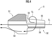
このとき、図4に示すように、前記薬液等の主流S1は、接続部材5の貫通孔53を通って外針2の内部に流入するが、接続部材5は挿入部52の側面に第2の開口部55を備えるので、該薬液等の一部が第2の開口部55から流出し支流S2が形成される。接続部材5の挿入部52がスリット45に挿入されることにより、第2の開口部55はスリット45の前後に跨る状態となっているので、前記薬液等の支流S2はスリット45の先端面に沿って流出する。前記薬液等の支流S2は、第2の開口部55から流出した後、挿入部52の外周にそって周方向に流れ、軸に対して第2の開口部55と対称となる側に形成されている平坦部56から、軸に対して第2の開口部55と対称となる側に形成されて嵌合部51の後端面に開口している第1の開口部54に流入する。第1の開口部54は貫通孔53に連通しているので、第1の開口部54に流入した支流S2は第1の開口部54から貫通孔53に流入し、主流S2に合流する。
At this time, as shown in FIG. 4, the main flow S 1 of the liquid medicine or the like is flows into the
この結果、外針基3の内部で挿入部52の周囲に滞留している血液を支流S2により押し流し、挿入部52の周囲から外針2の内部に流入させることができ、該血液を短時間で完全に外針基3の内部から排出することができる。
As a result, sweeping away the blood that is accumulated on the periphery of the
また、止血弁4のスリット45は、加工精度により底部41の中央から外れて形成されることがある。しかし、本実施形態の留置針組立体1では、図1に示すように、接続部材5の嵌合部51は外針基3の拡径部32に対して遊嵌されており、嵌合部51の外周面と、拡径部32及び第1の直胴部33の内周面との間には間隙がある。
Further, the
そこで、図5に示すように、接続部材5は、外針基3の軸Oに対して任意の角度で傾斜することができ、スリット45が止血弁4の底部41の中央から外れて形成されているときには、外針基3の軸Oに対して傾斜した挿入部52がスリット45を指向したときに、挿入部52をスリット45に挿入することができる。
Therefore, as shown in FIG. 5, the connecting
1…留置針組立体、 2…外針、 3…外針基、 4…止血弁、 5…接続部材、 6…ルアー端子、 36…ルアーテーパー部、 44…通気フィルター、 45…スリット、 51…嵌合部、 52…挿入部、 54…第1の開口部、 55…第2の開口部。 1 ... indwelling needle assembly, 2 ... outer needle, 3 ... outer needle base, 4 ... hemostatic valve, 5 ... connection member, 6 ... luer terminal, 36 ... luer taper part, 44 ... ventilation filter, 45 ... slit, 51 ... Fitting part, 52 ... Inserting part, 54 ... First opening, 55 ... Second opening.
Claims (2)
中空筒状体からなり該外針を先端部で支持する一方、後端部にルアー端子を接続可能なルアーテーパー部を備え内部を透視可能な外針基と、
該外針基の軸方向に直交する面に開閉自在のスリットを備える止血弁と、
該外針基の内周面と該止血弁の外周面との間隙を封止し、気体を通過させる一方、液体を遮断する通気フィルターと、
中空筒状体からなり該外針基の内部の先端部に配置され、該止血弁が該ルアー端子により先端方向に押動されたときに後端部が該スリットに挿入されて該スリットの前後を連通させる接続部材とを備える留置針組立体であって、
該接続部材は、該外針基の内部の先端部に嵌合される嵌合部と、該嵌合部の後端側に連接されて該スリットに挿入される該嵌合部より小径の挿入部と、少なくとも該嵌合部の後端面に開口し中空筒状の内部に連通する第1の開口部と、軸に対して該第1の開口部と対称となる側で該挿入部の側面に開口し中空筒状の内部に連通する第2の開口部とを備えることを特徴とする留置針組立体。 An external needle that consists of a hollow tubular body and is placed in a state of being punctured into a blood vessel,
An outer needle base made of a hollow tubular body, which supports the outer needle at the tip, and has a luer taper portion at the rear end to which a luer terminal can be connected so that the inside can be seen through.
A hemostatic valve having a slit that can be opened and closed on a surface orthogonal to the axial direction of the outer needle base.
A ventilation filter that seals the gap between the inner peripheral surface of the outer needle base and the outer peripheral surface of the hemostatic valve to allow gas to pass through while blocking liquid.
It is composed of a hollow tubular body and is arranged at the tip inside the outer needle base, and when the hemostatic valve is pushed toward the tip by the luer terminal, the rear end is inserted into the slit and the front and back of the slit. An indwelling needle assembly comprising a connecting member for communicating with each other.
The connecting member has a fitting portion fitted to the inner tip portion of the outer needle base and an insertion portion having a diameter smaller than that of the fitting portion connected to the rear end side of the fitting portion and inserted into the slit. A portion, a first opening that opens at least at the rear end surface of the fitting portion and communicates with the inside of the hollow tubular shape, and a side surface of the insertion portion on a side that is symmetrical to the first opening with respect to the axis. An indwelling needle assembly comprising a second opening that opens into a hollow cylinder and communicates with the inside.
Priority Applications (3)
| Application Number | Priority Date | Filing Date | Title |
|---|---|---|---|
| JP2017142274A JP6889820B2 (en) | 2017-07-21 | 2017-07-21 | Indwelling needle assembly |
| PCT/JP2018/023127 WO2019017129A1 (en) | 2017-07-21 | 2018-06-18 | Indwelling needle assembly |
| TW107122233A TWI761543B (en) | 2017-07-21 | 2018-06-28 | Indwelling needle assembly |
Applications Claiming Priority (1)
| Application Number | Priority Date | Filing Date | Title |
|---|---|---|---|
| JP2017142274A JP6889820B2 (en) | 2017-07-21 | 2017-07-21 | Indwelling needle assembly |
Publications (2)
| Publication Number | Publication Date |
|---|---|
| JP2019022544A JP2019022544A (en) | 2019-02-14 |
| JP6889820B2 true JP6889820B2 (en) | 2021-06-18 |
Family
ID=65015258
Family Applications (1)
| Application Number | Title | Priority Date | Filing Date |
|---|---|---|---|
| JP2017142274A Active JP6889820B2 (en) | 2017-07-21 | 2017-07-21 | Indwelling needle assembly |
Country Status (3)
| Country | Link |
|---|---|
| JP (1) | JP6889820B2 (en) |
| TW (1) | TWI761543B (en) |
| WO (1) | WO2019017129A1 (en) |
Families Citing this family (3)
| Publication number | Priority date | Publication date | Assignee | Title |
|---|---|---|---|---|
| JP7091593B2 (en) * | 2018-07-25 | 2022-06-28 | 株式会社トップ | Indwelling needle assembly |
| JPWO2021215437A1 (en) * | 2020-04-21 | 2021-10-28 | ||
| CN113893413A (en) * | 2021-08-31 | 2022-01-07 | 苏州鑫康道医疗科技有限公司 | Remaining needle with blood blocking and acupuncture preventing functions |
Family Cites Families (11)
| Publication number | Priority date | Publication date | Assignee | Title |
|---|---|---|---|---|
| JPH061080B2 (en) * | 1989-09-04 | 1994-01-05 | 喜義 春日井 | Vane pump |
| JP4996015B2 (en) * | 2001-03-12 | 2012-08-08 | メディキット株式会社 | Indwelling catheter |
| JP2008043445A (en) * | 2006-08-11 | 2008-02-28 | Medikit Kk | Catheter, hollow needle and dwelling needle assembly |
| BRPI0920464B8 (en) * | 2008-10-03 | 2021-06-22 | Nipro Corp | needle tip protector and permanent needle mount |
| US8361038B2 (en) * | 2009-02-11 | 2013-01-29 | Becton, Dickinson And Company | Systems and methods for providing a flow control valve for a medical device |
| US8679063B2 (en) * | 2009-02-11 | 2014-03-25 | Becton, Dickinson And Company | Systems and methods for providing a catheter assembly |
| JP5651597B2 (en) * | 2009-10-16 | 2015-01-14 | テルモ株式会社 | Indwelling needle and indwelling needle assembly |
| US9381320B2 (en) * | 2013-03-18 | 2016-07-05 | Becton, Dickinson And Company | Multiple-use intravenous catheter assembly septum and septum actuator |
| JP6295059B2 (en) * | 2013-10-24 | 2018-03-14 | 株式会社トップ | Indwelling needle |
| WO2015133279A1 (en) * | 2014-03-05 | 2015-09-11 | テルモ株式会社 | Catheter assembly |
| JP7091593B2 (en) * | 2018-07-25 | 2022-06-28 | 株式会社トップ | Indwelling needle assembly |
-
2017
- 2017-07-21 JP JP2017142274A patent/JP6889820B2/en active Active
-
2018
- 2018-06-18 WO PCT/JP2018/023127 patent/WO2019017129A1/en not_active Ceased
- 2018-06-28 TW TW107122233A patent/TWI761543B/en active
Also Published As
| Publication number | Publication date |
|---|---|
| JP2019022544A (en) | 2019-02-14 |
| TWI761543B (en) | 2022-04-21 |
| WO2019017129A1 (en) | 2019-01-24 |
| TW201907974A (en) | 2019-03-01 |
Similar Documents
| Publication | Publication Date | Title |
|---|---|---|
| US5242411A (en) | Piercing needle having hydrophobic filter vent | |
| KR920007267B1 (en) | Flash chamber | |
| CA1125616A (en) | Intravascular catheter | |
| JP6889820B2 (en) | Indwelling needle assembly | |
| JP2008043445A (en) | Catheter, hollow needle and dwelling needle assembly | |
| GB1566564A (en) | Apparatus for withdraving and replacing fluid within a body vessel | |
| CN102711895A (en) | Placement needle and placement needle assembly | |
| JP2016067455A (en) | Indwelling needle for extracorporeal circulation | |
| JP7091593B2 (en) | Indwelling needle assembly | |
| JP6591065B2 (en) | Filter syringe | |
| JP2012071052A (en) | Indwelling needle and method for manufacturing the indwelling needle | |
| JP4264886B2 (en) | Balloon catheter | |
| JP2000116791A (en) | Indwelling canula assembly and valve plug | |
| JP6638066B2 (en) | Syringe | |
| JP2004248987A (en) | Guide-wire inserting tool | |
| JPS5832774A (en) | Staying needle | |
| JP6787626B2 (en) | Needle assembly with flashback chamber for collecting blood or other liquid samples | |
| US20220023598A1 (en) | Integrated Catheter-Placement Devices and Methods for Mitigating Blood Egress | |
| JP2009232916A (en) | Catheter indwelling appliance | |
| JPWO2015133279A1 (en) | Catheter assembly | |
| JP7000666B2 (en) | Indwelling needle | |
| JP7053978B2 (en) | Indwelling needle | |
| JPWO2015098590A1 (en) | Indwelling needle assembly | |
| JP2010264024A (en) | Blood sampling catheter | |
| JP6978658B2 (en) | Indwelling needle |
Legal Events
| Date | Code | Title | Description |
|---|---|---|---|
| A621 | Written request for application examination |
Free format text: JAPANESE INTERMEDIATE CODE: A621 Effective date: 20200630 |
|
| TRDD | Decision of grant or rejection written | ||
| A01 | Written decision to grant a patent or to grant a registration (utility model) |
Free format text: JAPANESE INTERMEDIATE CODE: A01 Effective date: 20210316 |
|
| A61 | First payment of annual fees (during grant procedure) |
Free format text: JAPANESE INTERMEDIATE CODE: A61 Effective date: 20210405 |
|
| R150 | Certificate of patent or registration of utility model |
Ref document number: 6889820 Country of ref document: JP Free format text: JAPANESE INTERMEDIATE CODE: R150 |
|
| R250 | Receipt of annual fees |
Free format text: JAPANESE INTERMEDIATE CODE: R250 |
|
| R250 | Receipt of annual fees |
Free format text: JAPANESE INTERMEDIATE CODE: R250 |