JP6889819B2 - Small intestine indwelling tube insertion aid - Google Patents
Small intestine indwelling tube insertion aid Download PDFInfo
- Publication number
- JP6889819B2 JP6889819B2 JP2016240748A JP2016240748A JP6889819B2 JP 6889819 B2 JP6889819 B2 JP 6889819B2 JP 2016240748 A JP2016240748 A JP 2016240748A JP 2016240748 A JP2016240748 A JP 2016240748A JP 6889819 B2 JP6889819 B2 JP 6889819B2
- Authority
- JP
- Japan
- Prior art keywords
- tip
- small intestine
- tube
- rod
- indwelling tube
- Prior art date
- Legal status (The legal status is an assumption and is not a legal conclusion. Google has not performed a legal analysis and makes no representation as to the accuracy of the status listed.)
- Active
Links
Images

Landscapes
- Medical Preparation Storing Or Oral Administration Devices (AREA)
- Media Introduction/Drainage Providing Device (AREA)
Description
本発明は、小腸留置チューブを胃に挿入する際に用いられる挿入補助具に関する。 The present invention relates to an insertion aid used when inserting a small intestinal indwelling tube into the stomach.
近年、食物を経口摂取できない患者のために、患者の腹部に体外から胃内に貫通した胃瘻を穿設し、胃瘻に胃瘻チューブを挿入して胃内に直接栄養物を供給することが行われている。前記胃瘻チューブとして、例えば、チューブ本体と、チューブ本体の先端に設けられて胃の内壁に係止される可撓性のバンパー部と、チューブ本体の基端部に設けられて体表に係止される体表係止部とを備えるものが知られている。 In recent years, for patients who cannot take food orally, a gastrostomy that penetrates into the stomach from outside the body is made in the patient's abdomen, and a gastrostomy tube is inserted into the gastrostomy to supply nutrients directly into the stomach. Is being done. The gastrostomy tube includes, for example, a tube body, a flexible bumper portion provided at the tip of the tube body and locked to the inner wall of the stomach, and a base end portion of the tube body, which are provided on the body surface. Those provided with a body surface locking portion to be stopped are known.
また、このような前記胃瘻チューブを胃瘻に挿入する際に用いられる、棒状の挿入補助具が知られている(例えば、特許文献1参照)。 Further, a rod-shaped insertion assisting tool used when inserting such a gastrostomy tube into a gastrostomy is known (see, for example, Patent Document 1).
前記棒状の挿入補助具を用いて、前記胃瘻チューブを胃瘻に挿入する際には、まず前記挿入補助具をチューブ本体内に挿入する。そして、チューブ本体の先端の内壁に、チューブ本体の軸線に向かって内側に突出する係止部を設けておき、該係止部に前記バンパー部の先端を係合させる。そこから、さらに押し込むことによりバンパー部をその軸線に沿って先端方向に向かって細長く変形させ、この状態で前記胃瘻チューブを胃瘻に挿入する。次いで、胃瘻に挿入されたバンパー部が胃内に達したら、挿入補助具をチューブ本体から抜き去ることにより、バンパー部を原状に復帰させて胃の内壁に係止することができる。 When inserting the gastrostomy tube into the gastrostomy using the rod-shaped insertion assisting tool, the insertion assisting tool is first inserted into the tube body. Then, a locking portion that projects inward toward the axis of the tube body is provided on the inner wall of the tip of the tube body, and the tip of the bumper portion is engaged with the locking portion. From there, the bumper portion is further deformed along its axis toward the tip, and the gastrostomy tube is inserted into the gastrostomy in this state. Then, when the bumper portion inserted into the gastrostomy reaches the stomach, the insertion aid can be removed from the tube body to restore the bumper portion to its original state and lock it to the inner wall of the stomach.
一方、十二指腸から続く小腸の一部、例えば空腸に直接薬剤、栄養等を投与するために、小腸留置チューブが用いられている。前記小腸留置チューブは、前記胃瘻チューブにおいて、前記チューブ本体を前記バンパー部の先にさらに延長した形状を備えている。 On the other hand, a small intestine indwelling tube is used to directly administer a drug, nutrition, or the like to a part of the small intestine extending from the duodenum, for example, the jejunum. The small intestine indwelling tube has a shape in which the tube body is further extended to the tip of the bumper portion in the gastrostomy tube.
前記小腸留置チューブは、基本的な形状が前記胃瘻チューブと共通しているので、前記胃瘻チューブと同様の挿入補助具によって胃瘻に挿入することが考えられる。ところが、前記小腸留置チューブに前記挿入補助具の先端が係止される係止部を形成すると、挿入補助具を抜き去った後、チューブ本体内を介して薬剤、栄養等を投与する際に、該係止部により薬剤、栄養等の流れが妨げられるという問題がある。 Since the small intestine indwelling tube has the same basic shape as the gastrostomy tube, it is conceivable that the small intestine indwelling tube is inserted into the gastrostomy by an insertion assisting tool similar to the gastrostomy tube. However, when a locking portion for locking the tip of the insertion aid is formed in the small intestine indwelling tube, when the drug, nutrition, etc. are administered through the tube body after the insertion aid is removed, There is a problem that the locking portion obstructs the flow of drugs, nutrients, and the like.
本発明は、かかる不都合を解消して、係止部を有さない小腸留置チューブを容易に胃瘻に挿入することができる小腸留置チューブの挿入補助具を提供することを目的とする。 An object of the present invention is to provide an insertion aid for a small intestine indwelling tube capable of easily inserting a small intestine indwelling tube having no locking portion into a gastrostomy by eliminating such inconvenience.
かかる目的を達成するために、本発明の小腸留置チューブの挿入補助具は、体表側から胃瘻を介して小腸に留置されるチューブ本体と、該チューブ本体の外周面の途中に設けられて胃の内壁に係止される可撓性のバンパー部とを備える小腸留置チューブを胃瘻に挿入する際に用いられる小腸留置チューブの挿入補助具であって、把持部と、該把持部の先端に設けられ前記チューブ本体に挿入される挿入部とを備え、該挿入部は、該チューブ本体に挿入されたときに、少なくとも該挿入部の先端部が前記バンパー部まで達する長さに形成されるとともに、該先端部の外周に外方に向かって変形自在であって、変形したときに該チューブ本体の内壁に圧接する圧接部を備えることを特徴とする。 In order to achieve such an object, the small intestine indwelling tube insertion assisting tool of the present invention is provided in the middle of the tube main body to be indwelled in the small intestine from the body surface side via a gastrostomy and the outer peripheral surface of the tube body. A small intestine indwelling tube insertion aid used when inserting a small intestine indwelling tube into a gastrostomy with a flexible bumper that is locked to the inner wall of the stomach. The insertion portion is provided and includes an insertion portion to be inserted into the tube body, and the insertion portion is formed to have a length at which at least the tip portion of the insertion portion reaches the bumper portion when inserted into the tube body. The outer periphery of the tip portion is provided with a pressure contact portion that is deformable outward and presses against the inner wall of the tube body when deformed.
本発明の小腸留置チューブの挿入補助具(以下、挿入補助具と略記する)は、前記チューブ本体と、前記バンパー部とを備える小腸留置チューブを胃瘻に挿入する際に用いられる。 The small intestine indwelling tube insertion assisting tool of the present invention (hereinafter, abbreviated as insertion assisting tool) is used when inserting the small intestine indwelling tube including the tube body and the bumper portion into a gastrostomy.
本発明の挿入補助具は、前記把持部の先端に設けられた前記挿入部の先端部の外周に、外方に向かって変形自在の圧接部を備えている。そこで、本発明の挿入補助具は、前記挿入部を前記小腸留置チューブの前記チューブ本体に挿入し、その先端部が少なくとも前記バンパー部を超える部分まで達したときに、前記圧接部を外方に向かって変形させることにより該圧接部を該チューブ本体の内壁に圧接させる。 The insertion assisting tool of the present invention is provided with a pressure contact portion that can be deformed outward on the outer periphery of the tip portion of the insertion portion provided at the tip of the grip portion. Therefore, the insertion assisting tool of the present invention inserts the insertion portion into the tube body of the small intestine indwelling tube, and when the tip portion reaches at least a portion exceeding the bumper portion, the pressure contact portion is moved outward. The pressure contact portion is pressed against the inner wall of the tube body by deforming toward the tube body.
そして、チューブ本体を先端から胃瘻に挿入していき、前記圧接部で前記チューブ本体の内壁に圧接させた状態で、本発明の挿入補助具によって小腸留置チューブを押し込むことにより、可撓性を有するバンパー部をその軸線に沿って基端方向に向かって細長く変形させることができる。従って、本発明の挿入補助具によれば、係止部を有さない小腸留置チューブであっても容易に胃瘻に挿入することができる。 Then, the tube body is inserted into the gastrostomy from the tip, and the small intestine indwelling tube is pushed by the insertion assisting tool of the present invention in a state where the tube body is pressed against the inner wall of the tube body at the pressure contact portion to increase the flexibility. The bumper portion to be held can be elongated and elongated toward the proximal end along the axis thereof. Therefore, according to the insertion aid of the present invention, even a small intestinal indwelling tube having no locking portion can be easily inserted into the gastrostomy.
以上のとおり、本発明の挿入補助具によれば、前記バンパー部を細長く変形させて前記小腸留置チューブを胃瘻に挿入し、該バンパー部が胃内に達することにより、バンパー部を原状に復帰させて胃の内壁に係止することができる。その後、本発明の挿入補助具は、前記圧接部の変形を原状に復帰させ前記チューブ本体の内壁に対する圧接を解除することにより該チューブ本体から抜き去ることができる。 As described above, according to the insertion assisting tool of the present invention, the bumper portion is elongated and deformed, the small intestine indwelling tube is inserted into the gastrostomy, and the bumper portion reaches the stomach to restore the bumper portion to its original state. It can be locked to the inner wall of the stomach. After that, the insertion assisting tool of the present invention can be removed from the tube body by restoring the deformation of the pressure contact portion to the original state and releasing the pressure contact with the inner wall of the tube body.
本発明の挿入補助具において、前記挿入部は中空筒状に形成されるとともに、該挿入部の内部を進退自在なロッドを備え、前記圧接部は、弾性体からなり、前記挿入部の該圧接部より先端側が前記ロッドの先端部に固定され、該ロッドが該挿入部の内部を相対的に後退したときに外方に向かって変形するよう構成することができる。 In the insertion assisting tool of the present invention, the insertion portion is formed in a hollow tubular shape and includes a rod that can move forward and backward inside the insertion portion. The pressure contact portion is made of an elastic body, and the pressure contact portion of the insertion portion is the pressure contact portion. The tip side of the portion is fixed to the tip portion of the rod, and the rod can be configured to deform outward when the inside of the insertion portion is relatively retracted.
前記構成によれば、前記挿入部を前記小腸留置チューブの前記チューブ本体に挿入し、その先端部が少なくとも前記バンパー部まで達したときに、前記挿入部に対して前記ロッドを後退させる。このようにすると、前記ロッドの先端は、挿入部の先端部に固定されているので、該挿入部の先端部が基端部に近づけられる方向、即ち、挿入部の長さが短くなる方向につぶされる圧力がかかる。この結果、圧接部は弾性体からなるので、外方に向かって変形されてチューブ本体の内壁を圧接する。 According to the configuration, the insertion portion is inserted into the tube body of the small intestine indwelling tube, and when the tip portion reaches at least the bumper portion, the rod is retracted with respect to the insertion portion. In this way, since the tip of the rod is fixed to the tip of the insertion portion, the tip of the insertion portion is brought closer to the base end portion, that is, the length of the insertion portion is shortened. There is pressure to be crushed. As a result, since the pressure-welded portion is made of an elastic body, it is deformed outward to press-contact the inner wall of the tube body.
また、前記構成によれば、前記挿入部に対して前記ロッドを前進させると、前記圧接部はそれ自体の弾性により原状に復帰するので、前記チューブ本体の内壁に対する圧接を解除することができる。 Further, according to the above configuration, when the rod is advanced with respect to the insertion portion, the pressure contact portion returns to its original state due to its own elasticity, so that the pressure contact with the inner wall of the tube body can be released.
さらに、上記構成を備える挿入補助具において、前記圧接部は、前記挿入部の先端に軸方向に沿って設けられた複数のスリットによって分割されていて前記ロッドが該挿入部の内部を相対的に後退したときに外方に向かって夫々屈曲する複数の板状部からなるよう構成することができる。 Further, in the insertion assisting tool having the above configuration, the pressure contact portion is divided by a plurality of slits provided along the axial direction at the tip of the insertion portion, and the rod is relatively inside the insertion portion. It can be configured to consist of a plurality of plate-shaped portions that bend outward when retracted.
前記構成によれば、前記挿入部の先端に軸方向に沿って複数のスリットを設けることにより、前記挿入部の先端部を分割することで、複数の板状部が形成される。そして、この各板状部は弾性体からなるので、ロッドが挿入部の内部を相対的に後退すると、外方に向かって夫々屈曲してチューブ本体の内壁を圧接する。 According to the above configuration, a plurality of plate-shaped portions are formed by providing a plurality of slits at the tip of the insertion portion along the axial direction and dividing the tip portion of the insertion portion. Since each of these plate-shaped portions is made of an elastic body, when the rod retracts relatively inside the insertion portion, it bends outward and presses against the inner wall of the tube body.
次に、添付の図面を参照しながら本発明の実施の形態についてさらに詳しく説明する。 Next, embodiments of the present invention will be described in more detail with reference to the accompanying drawings.
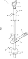
図1に示す本実施形態のオブチュレーター(挿入補助具)1は、小腸留置チューブ10を図示しない胃瘻に挿入する際に用いられる。まず、本実施形態のオブチュレーター(挿入補助具)1が用いられる小腸留置チューブ10について説明する。
The obturator (insertion aid) 1 of the present embodiment shown in FIG. 1 is used when the small
図1に示すように、小腸留置チューブ10は、チューブ本体11と、チューブ本体11の外周面の途中に設けられた可撓性を有するシリコーンゴム製のバンパー部12と、チューブ本体11の基端に径方向外方に延設された体表係止部13とからなる。チューブ本体11はバンパー部12の前後で同一の内径を備えている。また、体表係止部13にはチューブ本体11に連通するポート14を閉塞する栓体15が連設されている。
As shown in FIG. 1, the small
小腸留置チューブ10において、バンパー部12は、先端方向に向かってドーム状に拡径するドーム壁部16と、チューブ本体11に固定された環状の固定部17とを備えている。ドーム壁部16は、平面視円形状に形成されており、その中央部に形成された挿通孔18には、チューブ本体11が挿通されている。挿通孔18は、その内径がチューブ本体11の外径よりも大きく形成されており、これにより、ドーム壁部16はチューブ本体11の長手方向への移動が許容されている。
In the small
また、ドーム壁部16と固定部17とは、周方向に所定間隔を存して設けられた複数(本実施形態では4つ)の連結部19により連結されている。各連結部19は湾曲する帯状に形成されており、ドーム壁部16と固定部17とを一体に連結している。ドーム壁部16と連結部19とは同じ肉厚で形成されているが、その形状の違いにより連結部19がドーム壁部16よりも撓みやすくなっている。
Further, the
次に、本実施形態のオブチュレーター(挿入補助具)1について説明する。図1及び図2に示すように、オブチュレーター1は、円筒状の把持部2と、把持部2の内部に進退自在に挿入される円筒状の押出部3と備える。押出部3の先端には、把持部2の先端から突出する円筒状の挿入部4が連設されている。なお、本実施形態では、押出部3及び挿入部4は円筒状に形成されているが、本発明はこれに限られず、角筒状など筒状であればよい。
Next, the obturator (insertion assisting tool) 1 of the present embodiment will be described. As shown in FIGS. 1 and 2, the
押出部3及び挿入部4の内部にはロッド5が進退自在に挿通されている。このロッド5は、把持部2の内部に固定されている。これにより、把持部2の内部を押出部3及び挿入部4が進退すると、ロッド5が押出部3及び挿入部4の内部を相対的に進退する。
A
以上の把持部2、押出部3、挿入部4及びロッド5の中心軸は一致しているため、以下、基端から先端に向かう方向を単に軸方向という。
Since the central axes of the
把持部2は、合成樹脂製の中空円筒状からなり、把持部2の軸心を境に左右対称に指掛け部21,21が設けられている。
The
把持部2の外径はポート14の内径以上に形成されている。また、把持部2の先端側には、外径がポート14の内径以下の小径部22が段差部23を介して設けられている。
The outer diameter of the
把持部2の内部は、軸方向に押出部3が進退自在な第1内部通路24となっている。
The inside of the
第1内部通路24の先端は、前記小径部22によって塞がれている。小径部22は、把持部2の軸心に沿って貫通孔25が設けられている。貫通孔25は、挿入部4の外径以上かつ押出部3の外径未満に形成されている。これにより、把持部2の先端から、挿入部4の突出は許容され、押出部3の突出は制限されている。
The tip of the first
第1内部通路24の中央部には、一対の柱部26,26が設けられている。軸方向と指掛け部21,21を結ぶ線とに直交する方向を上下方向と定義すると、柱部26,26は、ロッド5を挟んだ状態で、第1内部通路24の上下面を結び、軸方向に延びている。ロッド5はこの柱部26,26に挟まれた状態で固定されている。
A pair of
なお、柱部26は、ロッド5を支持できればよいため、第1内部通路24の上面から下面まで達しなくても、一方面から軸心を超える程度の高さを持っていればよい。また、柱部26の個数に限定はなく、1つの柱部にロッド5を固定してもよく、上面及び下面から夫々2つずつ、合計4つの柱部26を設けてロッド5を挟持してもよい。
Since the
以上の把持部2は、本実施形態では、射出成形によって、上下2つのパーツからなり、組立可能になっている。
In the present embodiment, the above-mentioned
押出部3は、合成樹脂製の中空円筒状からなり、基端には操作部31が設けられている。操作部31は、正面視でO字状に形成されている。操作部31を軸方向に操作することにより、押出部3及び挿入部4は、前記第1内部通路24内を進退する。
The extruded
押出部3の内部は、軸方向にロッド5が相対的に進退自在な第2内部通路32となっている。第2内部通路32のうち、柱部26,26に対応する位置には、上下方向に貫通して軸方向に延びる溝部33が設けられている。溝部33の幅(図2の上下方向)は、柱部26,26の幅以上に形成されている。これにより、操作部31を操作した際、溝部33の内部において柱部26,26の相対的な進退が許容される。
The inside of the extruded
押出部3の先端には孔部34が設けられており、この孔部34に挿入部4の基端が差し込まれて支持されている。
A
挿入部4は、合成樹脂製の中空円筒状の弾性部材からなり、その外径はチューブ本体11の内径未満であるためチューブ本体11に挿入可能である。
The
挿入部4の内部は、前記第2内部通路32とは連通されて、軸方向にロッド5が相対的に進退自在な第3内部通路41となっている。
The inside of the
挿入部4の先端部には、複数(本実施形態では4つ)のスリット42が形成されている。これにより、該先端部は、円筒が分割されて形成された瓦状(本発明の板状部に相当)の圧接部43が複数(本実施形態では4つ)形成されている。
A plurality of slits 42 (four in the present embodiment) are formed at the tip of the
挿入部4は、同じ肉厚の円筒状に形成されているが、スリット42で分割されて細くなっている形状の相違によって、圧接部43は他の領域より撓みやすくなっている。なお、本実施形態では、挿入部4全体を弾性部材によって形成したが、本発明はこれに限られるものではなく、圧接部43が弾性変形可能であればよい。
The
挿入部4は、小腸留置チューブ10のチューブ本体11に挿入したとき、少なくとも圧接部43がバンパー部12の基端を超える位置、より好ましくは圧接部43が少なくとも固定部17まで達する長さを備えるよう形成されている。
The
ロッド5の先端には、挿入部4の先端開口の内径より大径の大径部51が設けられ、挿入部4の先端に掛止されている。なお、大径部51を設けることなく、ロッド5の先端と挿入部4の先端とを接着等により固定することもできる。
A
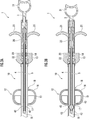
次に、図3A及び図3Bを参照して、本実施形態のオブチュレーター1を小腸留置チューブ10に装着する際のオブチュレーター1の作動について説明する。
Next, the operation of the
まず、把持部2を把持して、小腸留置チューブ10の体表係止部13に形成されたポート14から、挿入部4をチューブ本体11内に挿入していく。これにより、小径部22まではポート14の内部まで挿入され、把持部2の段差部23はポート14の端部に接して、オブチュレーター1のさらなる挿入が制限される。
First, the
このとき、挿入部4は前述した所定の長さを有するため、圧接部43は、チューブ本体11内において、固定部17に対応する位置または固定部17より先端側に配置される。
At this time, since the
次に、把持部2の指掛け部21,21に指を掛け、操作部31を先端側に押し込む。これにより、把持部2と把持部2に固定されたロッド5とに対して、押出部3及び挿入部4が前進しようとする。しかしながら、挿入部4は、ロッド5の大径部51によって掛止されているので、挿入部4は相対的に軸方向の両側から軸が短くなる方向に圧せられた状態になる。このとき、挿入部4は前述のとおり弾性変形可能であるため、分割により幅狭になっている圧接部43は、図3Bに示すように、外方に向けて弾性的に変形される。本実施形態では、圧接部43の先端、中央部及び基端に周方向に沿って夫々折目線が設けられているため、圧接部43は断面視V字状に屈曲される。
Next, a finger is hung on the finger hooks 21 and 21 of the
この結果、圧接部43がチューブ本体11の内壁に圧接され、オブチュレーター1が小腸留置チューブ10に装着される。
As a result, the
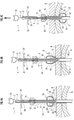
次に、図4A乃至図4Cを参照して、オブチュレーター1を用いて小腸留置チューブ10を胃瘻に挿入する方法について説明する。
Next, a method of inserting the small
オブチュレーター1を用いて小腸留置チューブ10を胃瘻に挿入するときには、まず、図4Aに示すように、オブチュレーター1を装着した小腸留置チューブ10のチューブ本体11の先端側を胃瘻Gに挿入し、バンパー部12を胃瘻Gの体表B側の開口部に当接する。
When inserting the small
次に、図4Bに示すように、オブチュレーター1によりチューブ本体11を胃壁S側に押圧すると、シリコーンゴムからなり可撓性を有するバンパー部12が体表Bに押されて挿通孔18がチューブ本体11に沿って上方に移動し、バンパー部12が細長く変形する。そこで、オブチュレーター1によりさらにチューブ本体11を胃壁S側に押圧することにより、細長く変形されたバンパー部12が胃瘻Gから胃壁S内、すなわち胃内に押入される。
Next, as shown in FIG. 4B, when the
このとき、挿入部4の圧接部43は、チューブ本体11内において、バンパー部12の先端側に配される固定部17より先端側を圧接しているため、バンパー部12を体表Bに押しつけたときに確実に細長く変形させることができる。
At this time, since the
次に、バンパー部12は胃壁S内に押入されると、それ自体の弾性により原状に復帰し、胃壁Sの内壁に係止され、小腸留置チューブ10の胃瘻Gへの挿入が完了する。
Next, when the
そこで、図4Cに示すように、操作部31を基端側に引っ張り押出部3及び挿入部4を後退させ、圧接部43を原状に復帰させ、これにより、チューブ本体11の内壁に対する圧接を解除する。そして、オブチュレーター1を図4Cに矢示するようにチューブ本体11から抜き去る。
Therefore, as shown in FIG. 4C, the
尚、本実施形態のオブチュレーター1は、小腸留置チューブ10に対するだけではなく、胃瘻チューブを胃瘻に挿入する際にも用いることができる。
The
1…オブチュレーター(挿入補助具)、 2…把持部、 4…挿入部、 5…ロッド、 6…花弁状部(圧接部)、 10…小腸留置チューブ、 11…チューブ本体、 12…バンパー部、 42…スリット、 43…圧接部43。
1 ... Obturator (insertion aid), 2 ... Grip part, 4 ... Insert part, 5 ... Rod, 6 ... Petal part (pressure welding part), 10 ... Small intestine indwelling tube, 11 ... Tube body, 12 ... Bumper part , 42 ... Slit, 43 ...
Claims (3)
筒状の把持部と、前記把持部の内部に進退自在に挿入される筒状の押出部と、前記押出部の先端に連設され前記把持部の先端から突出する筒状の挿入部と、前記把持部の内部に固定され、前記押出部及び前記挿入部の内部を進退自在に挿通されたロッドと、を備え、
前記押出部の基端には、前記把持部の基端から突出され、軸方向先端側に押し込む操作をすることにより、前記把持部の内部を前記押出部及び前記挿入部が前進することで前記押出部及び前記挿入部の内部を前記ロッドが相対的に後退し、かつ、軸方向基端側に引っ張る操作をすることにより前記把持部の内部を前記押出部及び前記挿入部が後退することで前記押出部及び前記挿入部の内部を前記ロッドが相対的に前進する操作部が設けられ、
前記挿入部は、前記チューブ本体に挿入されたときに、少なくとも前記挿入部の先端部が前記バンパー部まで達する長さに形成されるとともに、前記先端部の外周に外方に向かって変形自在であって、変形したときに前記チューブ本体の内壁に圧接する圧接部を備え、
前記圧接部は、弾性体からなり、前記挿入部の前記圧接部より先端側が前記ロッドの先端部に固定され、前記ロッドが前記押出部及び前記挿入部の内部を相対的に後退したときに外方に向かって変形することを特徴とする小腸留置チューブの挿入補助具。 A small intestine indwelling tube including a tube body that is placed in the small intestine from the body surface side via a gastrostomy and a flexible bumper portion that is provided in the middle of the outer peripheral surface of the tube body and is locked to the inner wall of the stomach. It is an insertion aid for the small intestine indwelling tube used when inserting into a gastrostomy.
A tubular grip portion, a tubular extruded portion that is freely inserted into the grip portion, and a tubular insert portion that is connected to the tip of the extruded portion and protrudes from the tip of the grip portion. A rod fixed to the inside of the grip portion and inserted into the extrusion portion and the inside of the insertion portion so as to be able to move forward and backward is provided.
The extruded portion and the inserted portion advance inside the gripped portion by projecting from the proximal end of the gripped portion and pushing the extruded portion toward the tip end side in the axial direction. The rod retracts relatively inside the extrusion portion and the insertion portion, and the extrusion portion and the insertion portion retract the inside of the grip portion by pulling the rod toward the axial base end side. An operation portion is provided in which the rod relatively advances inside the extrusion portion and the insertion portion.
The insertion portion is formed to have a length at which at least the tip portion of the insertion portion reaches the bumper portion when inserted into the tube body, and is freely deformable outward on the outer periphery of the tip portion. It is provided with a pressure contact portion that presses against the inner wall of the tube body when deformed.
The pressure-welding portion is made of an elastic body, and the tip end side of the insertion portion from the pressure-welding portion is fixed to the tip portion of the rod. A small intestinal indwelling tube insertion aid characterized by deforming toward the direction.
前記把持部には、その内部に該把持部の内周面から軸方向に直交する方向に向かって延びて前記ロッドを支持する柱部が設けられ、The grip portion is provided with a pillar portion that extends from the inner peripheral surface of the grip portion in a direction orthogonal to the axial direction to support the rod.
前記押出部には、軸方向に直交する方向に該押出部を貫通する溝部が設けられ、The extruded portion is provided with a groove portion penetrating the extruded portion in a direction orthogonal to the axial direction.
前記溝部は、前記押出部の前記柱部に対応する位置に設けられることでその内部に前記柱部を収納し、前記操作部を操作したときに溝部の内部において柱部の相対的な進退が許容されるように、軸方向に所定の長さ延設されていることを特徴とする小腸留置チューブの挿入補助具。The groove portion is provided at a position corresponding to the pillar portion of the extrusion portion, so that the pillar portion is housed inside the groove portion, and when the operation portion is operated, the relative advance / retreat of the pillar portion is performed inside the groove portion. An insertion aid for a small intestinal indwelling tube, characterized in that it extends a predetermined length in the axial direction so as to be tolerated.
前記圧接部は、前記挿入部の先端に軸方向に沿って設けられた複数のスリットによって分割されていて前記ロッドが該挿入部の内部を相対的に後退したときに外方に向かって夫々屈曲する複数の板状部からなることを特徴とする小腸留置チューブの挿入補助具。 In the insertion aid for the small intestine indwelling tube according to claim 1 or 2.
The pressure contact portion is divided by a plurality of slits provided along the axial direction at the tip of the insertion portion, and each rod bends outward when the rod retracts relatively inside the insertion portion. A small intestinal indwelling tube insertion aid characterized by being composed of a plurality of plate-shaped parts.
Priority Applications (1)
| Application Number | Priority Date | Filing Date | Title |
|---|---|---|---|
| JP2016240748A JP6889819B2 (en) | 2016-12-12 | 2016-12-12 | Small intestine indwelling tube insertion aid |
Applications Claiming Priority (1)
| Application Number | Priority Date | Filing Date | Title |
|---|---|---|---|
| JP2016240748A JP6889819B2 (en) | 2016-12-12 | 2016-12-12 | Small intestine indwelling tube insertion aid |
Publications (2)
| Publication Number | Publication Date |
|---|---|
| JP2018094037A JP2018094037A (en) | 2018-06-21 |
| JP6889819B2 true JP6889819B2 (en) | 2021-06-18 |
Family
ID=62631841
Family Applications (1)
| Application Number | Title | Priority Date | Filing Date |
|---|---|---|---|
| JP2016240748A Active JP6889819B2 (en) | 2016-12-12 | 2016-12-12 | Small intestine indwelling tube insertion aid |
Country Status (1)
| Country | Link |
|---|---|
| JP (1) | JP6889819B2 (en) |
Families Citing this family (1)
| Publication number | Priority date | Publication date | Assignee | Title |
|---|---|---|---|---|
| CN114010919B (en) * | 2021-11-17 | 2023-09-19 | 中国人民解放军陆军特色医学中心 | Full small intestine decompression tube for improving pleuroperitoneal cavity compliance and gas exchange efficiency |
Family Cites Families (5)
| Publication number | Priority date | Publication date | Assignee | Title |
|---|---|---|---|---|
| US4758219A (en) * | 1985-05-17 | 1988-07-19 | Microvasive, Inc. | Enteral feeding device |
| JP4239163B2 (en) * | 2003-01-08 | 2009-03-18 | 日本シャーウッド株式会社 | Gastrostomy tube |
| JP5018522B2 (en) * | 2008-02-06 | 2012-09-05 | 住友ベークライト株式会社 | Method for preparing insertion of indwelling catheter kit for fistula and indwelling catheter kit for fistula |
| US8523818B2 (en) * | 2009-01-19 | 2013-09-03 | Kimberly-Clark Worldwide, Inc. | Enteral feeding assembly with obturator |
| JP2014236891A (en) * | 2013-06-10 | 2014-12-18 | コニカミノルタ株式会社 | Catheter |
-
2016
- 2016-12-12 JP JP2016240748A patent/JP6889819B2/en active Active
Also Published As
| Publication number | Publication date |
|---|---|
| JP2018094037A (en) | 2018-06-21 |
Similar Documents
| Publication | Publication Date | Title |
|---|---|---|
| US8523818B2 (en) | Enteral feeding assembly with obturator | |
| CA2182104C (en) | Gastrostomy tube with improved internal retaining member | |
| CA2812720C (en) | Configurable percutaneous endoscopic gastrostomy tube | |
| JP4772042B2 (en) | Retaining device for medical components | |
| US8192419B2 (en) | Catheter assembly including internal bolster | |
| JP4782012B2 (en) | Medical catheter assembly including multi-piece connector | |
| JP6908040B2 (en) | Connector cap and connector with cap | |
| CN103182101A (en) | Body fluid drainage system | |
| JP6889819B2 (en) | Small intestine indwelling tube insertion aid | |
| JP2009273608A (en) | Fistula catheter and fistula catheter set | |
| JP6094262B2 (en) | Gastrostomy catheter | |
| JP6402880B2 (en) | Double female connector | |
| JP6704257B2 (en) | Insertion aid for small intestine indwelling tube | |
| EP3429548B1 (en) | Enteral feeding device connector | |
| JP5762017B2 (en) | Fistula catheter | |
| CN103041494B (en) | catheter | |
| JP6334948B2 (en) | Button type gastrostomy tube | |
| JP5576447B2 (en) | catheter | |
| JP2013143998A (en) | Medical tube connector | |
| JP6410529B2 (en) | Transgastric jejunum tube | |
| JP6680519B2 (en) | Gastrostomy tube |
Legal Events
| Date | Code | Title | Description |
|---|---|---|---|
| A621 | Written request for application examination |
Free format text: JAPANESE INTERMEDIATE CODE: A621 Effective date: 20191113 |
|
| A977 | Report on retrieval |
Free format text: JAPANESE INTERMEDIATE CODE: A971007 Effective date: 20200918 |
|
| A131 | Notification of reasons for refusal |
Free format text: JAPANESE INTERMEDIATE CODE: A131 Effective date: 20200929 |
|
| A521 | Request for written amendment filed |
Free format text: JAPANESE INTERMEDIATE CODE: A523 Effective date: 20201130 |
|
| TRDD | Decision of grant or rejection written | ||
| A01 | Written decision to grant a patent or to grant a registration (utility model) |
Free format text: JAPANESE INTERMEDIATE CODE: A01 Effective date: 20210323 |
|
| A61 | First payment of annual fees (during grant procedure) |
Free format text: JAPANESE INTERMEDIATE CODE: A61 Effective date: 20210405 |
|
| R150 | Certificate of patent or registration of utility model |
Ref document number: 6889819 Country of ref document: JP Free format text: JAPANESE INTERMEDIATE CODE: R150 |
|
| R250 | Receipt of annual fees |
Free format text: JAPANESE INTERMEDIATE CODE: R250 |
|
| R250 | Receipt of annual fees |
Free format text: JAPANESE INTERMEDIATE CODE: R250 |