JP6908040B2 - Connector cap and connector with cap - Google Patents
Connector cap and connector with cap Download PDFInfo
- Publication number
- JP6908040B2 JP6908040B2 JP2018525262A JP2018525262A JP6908040B2 JP 6908040 B2 JP6908040 B2 JP 6908040B2 JP 2018525262 A JP2018525262 A JP 2018525262A JP 2018525262 A JP2018525262 A JP 2018525262A JP 6908040 B2 JP6908040 B2 JP 6908040B2
- Authority
- JP
- Japan
- Prior art keywords
- connector
- cap
- protrusion
- outer cylinder
- female screw
- Prior art date
- Legal status (The legal status is an assumption and is not a legal conclusion. Google has not performed a legal analysis and makes no representation as to the accuracy of the status listed.)
- Active
Links
Images


Classifications
-
- A—HUMAN NECESSITIES
- A61—MEDICAL OR VETERINARY SCIENCE; HYGIENE
- A61M—DEVICES FOR INTRODUCING MEDIA INTO, OR ONTO, THE BODY; DEVICES FOR TRANSDUCING BODY MEDIA OR FOR TAKING MEDIA FROM THE BODY; DEVICES FOR PRODUCING OR ENDING SLEEP OR STUPOR
- A61M39/00—Tubes, tube connectors, tube couplings, valves, access sites or the like, specially adapted for medical use
- A61M39/02—Access sites
-
- A—HUMAN NECESSITIES
- A61—MEDICAL OR VETERINARY SCIENCE; HYGIENE
- A61J—CONTAINERS SPECIALLY ADAPTED FOR MEDICAL OR PHARMACEUTICAL PURPOSES; DEVICES OR METHODS SPECIALLY ADAPTED FOR BRINGING PHARMACEUTICAL PRODUCTS INTO PARTICULAR PHYSICAL OR ADMINISTERING FORMS; DEVICES FOR ADMINISTERING FOOD OR MEDICINES ORALLY; BABY COMFORTERS; DEVICES FOR RECEIVING SPITTLE
- A61J15/00—Feeding-tubes for therapeutic purposes
- A61J15/0026—Parts, details or accessories for feeding-tubes
-
- A—HUMAN NECESSITIES
- A61—MEDICAL OR VETERINARY SCIENCE; HYGIENE
- A61M—DEVICES FOR INTRODUCING MEDIA INTO, OR ONTO, THE BODY; DEVICES FOR TRANSDUCING BODY MEDIA OR FOR TAKING MEDIA FROM THE BODY; DEVICES FOR PRODUCING OR ENDING SLEEP OR STUPOR
- A61M39/00—Tubes, tube connectors, tube couplings, valves, access sites or the like, specially adapted for medical use
- A61M39/10—Tube connectors; Tube couplings
- A61M39/1011—Locking means for securing connection; Additional tamper safeties
-
- A—HUMAN NECESSITIES
- A61—MEDICAL OR VETERINARY SCIENCE; HYGIENE
- A61M—DEVICES FOR INTRODUCING MEDIA INTO, OR ONTO, THE BODY; DEVICES FOR TRANSDUCING BODY MEDIA OR FOR TAKING MEDIA FROM THE BODY; DEVICES FOR PRODUCING OR ENDING SLEEP OR STUPOR
- A61M39/00—Tubes, tube connectors, tube couplings, valves, access sites or the like, specially adapted for medical use
- A61M39/20—Closure caps or plugs for connectors or open ends of tubes
Landscapes
- Health & Medical Sciences (AREA)
- Heart & Thoracic Surgery (AREA)
- Life Sciences & Earth Sciences (AREA)
- Veterinary Medicine (AREA)
- Public Health (AREA)
- General Health & Medical Sciences (AREA)
- Animal Behavior & Ethology (AREA)
- Engineering & Computer Science (AREA)
- Hematology (AREA)
- Biomedical Technology (AREA)
- Anesthesiology (AREA)
- Pulmonology (AREA)
- Infusion, Injection, And Reservoir Apparatuses (AREA)
- External Artificial Organs (AREA)
- Catching Or Destruction (AREA)
Description
本発明は、コネクタに着脱可能なキャップに関する。また、本発明は、着脱可能なキャップを備えたコネクタに関する。 The present invention relates to a cap that can be attached to and detached from a connector. The present invention also relates to a connector having a removable cap.
医療の分野では、液状物を流すための流路が用いられる。例えば、経腸栄養法では、食事を口から摂れなくなった患者に、カテーテルを介して、栄養剤、流動食(一般に「経腸栄養剤」と呼ばれる)、又は薬剤などの液状物が投与される。カテーテルは、体外から消化管(例えば胃)内に挿入した状態で患者に留置される。カテーテルとしては、患者の鼻から挿入する経鼻カテーテルや、患者の腹に形成された胃ろうに挿入するPEG(Percutaneous Endoscopic Gastrostomy)カテーテル等が知られている。患者に液状物を投与する際には、液状物を貯留した容器と、患者に留置されたカテーテル(経鼻カテーテル、PEGカテーテルなど)とが柔軟なチューブ等を介して接続される。異なる部材を接続するために、オスコネクタとメスコネクタとからなる接続具が用いられる。 In the medical field, channels for flowing liquids are used. For example, in enteral nutrition, a liquid substance such as a nutritional supplement, a liquid diet (generally referred to as "enteral nutritional supplement"), or a drug is administered to a patient who cannot eat food by mouth via a catheter. .. The catheter is placed in the patient with it inserted into the gastrointestinal tract (eg, stomach) from outside the body. As the catheter, a nasal catheter inserted through the nose of a patient, a PEG (Percutaneous Endoscopic Gastrostomy) catheter inserted into a gastrostomy formed in the abdomen of a patient, and the like are known. When the liquid substance is administered to the patient, the container in which the liquid substance is stored and the catheter (nasal catheter, PEG catheter, etc.) indwelled in the patient are connected via a flexible tube or the like. In order to connect different members, a connector consisting of a male connector and a female connector is used.
従来の一般的な接続具は、先細のテーパ面を有するオスコネクタと、当該オスコネクタが挿入される、中空の筒状形状を有するメスコネクタとを含む(例えば特許文献1参照)。このようなオスコネクタとメスコネクタとの接続方式は、一般に「スリップ接続」と呼ばれる。 Conventional general connectors include a male connector having a tapered tapered surface and a female connector having a hollow tubular shape into which the male connector is inserted (see, for example, Patent Document 1). Such a connection method between the male connector and the female connector is generally called "slip connection".
スリップ接続では、オスコネクタとメスコネクタとの接続状態は、両者の間に発生する摩擦力によって維持される。スリップ接続は一般に接続強度が低く、引張り力や流路内の圧力上昇によって、オスコネクタとメスコネクタとが意図せずに分離してしまうことがある。 In the slip connection, the connection state between the male connector and the female connector is maintained by the frictional force generated between them. The slip connection generally has a low connection strength, and the male connector and the female connector may be unintentionally separated due to a tensile force or an increase in pressure in the flow path.
オスコネクタとメスコネクタとの接続強度を向上させる方法として、互いに螺合する螺合構造(即ち、雄ネジと雌ネジ)をオスコネクタ及びメスコネクタに設けることが考えられる。 As a method of improving the connection strength between the male connector and the female connector, it is conceivable to provide the male connector and the female connector with a screw structure (that is, a male screw and a female screw) that are screwed together.
ところで、経腸栄養法では、カテーテル内の流路を清潔に保つために、液状物の投与を行わないときには、患者に留置されるカテーテルの上流側端に設けられたコネクタ(以下「患者側コネクタ」という)に、その開口を塞ぐようにキャップを装着することが一般的である(例えば特許文献2参照)。患者側コネクタに、接続強度を向上させるために雌ネジを設けた場合、患者側コネクタの構成に応じてキャップの構成を変更することが望まれる。 By the way, in enteral nutrition, in order to keep the flow path in the catheter clean, a connector provided at the upstream end of the catheter indwelled in the patient when the liquid substance is not administered (hereinafter, "patient side connector"). ”), It is common to attach a cap so as to close the opening (see, for example, Patent Document 2). When the patient-side connector is provided with a female screw in order to improve the connection strength, it is desirable to change the cap configuration according to the configuration of the patient-side connector.
更に、患者側コネクタにキャップを装着した状態で胃の内圧が上昇すると、キャップは患者側コネクタから分離されるような圧力を受ける。このような場合にもキャップが患者側コネクタから脱落しないように、キャップの患者側コネクタに対する装着強度は高いことが望まれる。また、キャップが装着された患者側コネクタが患者の体や顔の下敷きになった場合に患者が痛みを感じないように、キャップはなるべく小さいことが望まれる。 Furthermore, when the internal pressure of the stomach rises with the cap attached to the patient-side connector, the cap receives a pressure that separates it from the patient-side connector. Even in such a case, it is desired that the cap has a high mounting strength with respect to the patient-side connector so that the cap does not fall off from the patient-side connector. It is also desirable that the cap be as small as possible so that the patient does not feel pain when the patient-side connector to which the cap is attached lays under the patient's body or face.
本発明の第1の目的は、雌ネジを備えたコネクタに着脱可能なキャップであって、コネクタから外れにくく且つ小型のキャップを提供することにある。本発明の第2の目的は、そのようなキャップを備えたコネクタを提供することにある。 A first object of the present invention is to provide a cap that can be attached to and detached from a connector having a female screw, which is hard to come off from the connector and is small in size. A second object of the present invention is to provide a connector with such a cap.
本発明のコネクタ用キャップは、円筒形状を有する外筒の内周面に設けられた雌ネジを備えるコネクタに着脱可能である。前記キャップは、前記外筒の開口を塞ぐことができるように構成された天板と、前記天板に設けられ且つ前記外筒に挿入することができるように構成されたリブと、前記リブの側面から突出した突起とを備える。前記突起は、前記雌ネジに係合することができるように、前記天板から離間して設けられている。 The connector cap of the present invention can be attached to and detached from a connector having a female screw provided on the inner peripheral surface of an outer cylinder having a cylindrical shape. The cap includes a top plate configured to close the opening of the outer cylinder, a rib provided on the top plate and configured to be inserted into the outer cylinder, and the rib. It has a protrusion protruding from the side surface. The protrusion is provided apart from the top plate so that it can be engaged with the female screw.
本発明のキャップ付きコネクタは、本発明の上記のキャップと前記コネクタとを備える。 The capped connector of the present invention includes the above-mentioned cap and the above-mentioned connector of the present invention.
本発明のキャップは、コネクタの外筒に挿入される筒状部の外周面に、コネクタの雌ネジに係合することができる突起を備える。このため、キャップは、コネクタから外れにくく、且つ、キャップを小型化することができる。更に、キャップをコネクタに装着する際に突起が雌ネジと係合する時にクリック感が生じるので、作業者はキャップをコネクタに常に適切に装着することができる。また、天板はコネクタの外筒の開口を塞ぐので、外筒の内周面に設けられた雌ネジを清潔に保つことができる。 The cap of the present invention includes a protrusion on the outer peripheral surface of the tubular portion inserted into the outer cylinder of the connector so that it can engage with the female screw of the connector. Therefore, the cap does not easily come off from the connector, and the cap can be miniaturized. Further, when the cap is attached to the connector, a click feeling is generated when the protrusion engages with the female screw, so that the operator can always properly attach the cap to the connector. Further, since the top plate closes the opening of the outer cylinder of the connector, the female screw provided on the inner peripheral surface of the outer cylinder can be kept clean.
本発明の前記キャップにおいて、前記リブは、円筒形状を有する筒状部であってもよい。この場合、前記突起は、前記筒状部の外周面に設けられていてもよい。筒状部が円筒形状を有することは、筒状部の機械的強度の向上に有利である。従って、このような筒状部に突起が設けられていることは、キャップをコネクタに装着したときに、突起を雌ネジに確実に係合させるのに有利である。 In the cap of the present invention, the rib may be a cylindrical portion having a cylindrical shape. In this case, the protrusion may be provided on the outer peripheral surface of the tubular portion. Having a cylindrical portion having a cylindrical shape is advantageous for improving the mechanical strength of the tubular portion. Therefore, the provision of the protrusion on such a tubular portion is advantageous for surely engaging the protrusion with the female screw when the cap is attached to the connector.
前記コネクタは、前記外筒に取り囲まれるように前記外筒と同軸に設けられたオス部材を備えていてもよい。前記オス部材の長手方向に沿って前記オス部材を貫通する流路が、前記オス部材の先端において開口していてもよい。この場合、前記筒状部は、前記キャップを前記コネクタに装着したとき、前記筒状部の内周面と前記オス部材の外周面との間に液密なシールが形成されるように構成されていてもよい。かかる構成は、流路の封止性の向上と、キャップのコネクタに対する装着強度の向上に有利である。更に、突起と雌ネジとの係合深さが増大されるので、キャップのコネクタに対する装着強度を更に向上させるのに有利である。 The connector may include a male member coaxially provided with the outer cylinder so as to be surrounded by the outer cylinder. A flow path penetrating the male member along the longitudinal direction of the male member may be open at the tip of the male member. In this case, the tubular portion is configured so that when the cap is attached to the connector, a liquid-tight seal is formed between the inner peripheral surface of the tubular portion and the outer peripheral surface of the male member. You may be. Such a configuration is advantageous in improving the sealing property of the flow path and improving the mounting strength of the cap to the connector. Further, since the engagement depth between the protrusion and the female screw is increased, it is advantageous to further improve the mounting strength of the cap to the connector.
前記コネクタは、前記外筒に取り囲まれるように前記外筒と同軸に設けられたオス部材を備えていてもよい。前記オス部材の長手方向に沿って前記オス部材を貫通する流路が、前記オス部材の先端において開口していてもよい。この場合、前記キャップは、前記流路の開口に嵌入するように構成された栓体を更に備えてもよい。かかる構成は、キャップのコネクタに対する装着強度の向上に有利である。また、栓体が流路に嵌入することにより、キャップは、コネクタに対して水平方向(オス部材の長手方向に垂直な平面に平行な方向)に位置決めされる。これは、突起を雌ネジに確実に係合させるのに有利である。 The connector may include a male member coaxially provided with the outer cylinder so as to be surrounded by the outer cylinder. A flow path penetrating the male member along the longitudinal direction of the male member may be open at the tip of the male member. In this case, the cap may further include a plug configured to fit into the opening of the flow path. Such a configuration is advantageous for improving the mounting strength of the cap with respect to the connector. Further, when the plug body is fitted into the flow path, the cap is positioned in the horizontal direction (the direction parallel to the plane perpendicular to the longitudinal direction of the male member) with respect to the connector. This is advantageous for ensuring that the protrusion engages the female thread.
前記栓体は、前記栓体が前記流路の開口に嵌入したとき、前記栓体の外周面と前記流路を規定する内周面との間に液密なシールが形成されるように構成されていてもよい。かかる構成は、胃の内圧上昇によりオス部材の流路の圧力が上昇したときに、キャップがコネクタから脱落する可能性を低減するのに有利である。また、栓体がオス部材に対して、流路から抜け出る向きにわずかに位置ズレしても、液密なシールを形成し続けるのに有利である。 The plug body is configured so that when the plug body is fitted into the opening of the flow path, a liquid-tight seal is formed between the outer peripheral surface of the plug body and the inner peripheral surface defining the flow path. It may have been done. Such a configuration is advantageous in reducing the possibility that the cap will fall out of the connector when the pressure in the flow path of the male member increases due to the increase in the internal pressure of the stomach. Further, even if the plug body is slightly displaced from the male member in the direction of exiting the flow path, it is advantageous to continue to form a liquid-tight seal.
本発明の前記キャップを前記コネクタに装着したとき、前記突起は前記雌ネジを構成するネジ山から離間するように構成されていてもよい。かかる構成によれば、キャップをコネクタに長期間にわたって装着し続けても、突起がネジ山によって永久変形されることがない。このため、突起の作用が長期にわたって衰えることなく奏される。 When the cap of the present invention is attached to the connector, the protrusion may be configured to be separated from the threads constituting the female screw. According to this configuration, the protrusions are not permanently deformed by the threads even if the cap is continuously attached to the connector for a long period of time. Therefore, the action of the protrusions is played for a long period of time without deterioration.
前記キャップは、前記コネクタより軟質の材料からなることが好ましい。これは、キャップのコネクタ本体部に対する着脱を容易にし、且つ、繰り返しの着脱に対する耐久性を向上するのに有利である。 The cap is preferably made of a material softer than the connector. This is advantageous in facilitating the attachment / detachment of the cap to the connector main body and improving the durability against repeated attachment / detachment.
前記キャップは、前記コネクタの中心軸周りに前記キャップが回転するのを制限する回転制限機構を更に備えてもよい。これにより、コネクタに対するキャップの着脱を繰り返しても、コネクタの雌ネジのネジ山に対する突起の位置を常に一定にすることができる。 The cap may further include a rotation limiting mechanism that limits the rotation of the cap around the central axis of the connector. As a result, even if the cap is repeatedly attached to and detached from the connector, the position of the protrusion of the female screw of the connector with respect to the thread can always be kept constant.
前記キャップは、前記天板の外周端縁から突出した操作タブを更に備えてもよい。この場合、前記操作タブは前記リブに対して前記突起と同じ側に配置されていてもよい。これは、キャップをコネクタから取り外す際に力が加えられる操作タブの近くに突起が配置されるので、キャップの取り外し作業を容易にするのに有利である。 The cap may further include an operation tab protruding from the outer peripheral edge of the top plate. In this case, the operation tab may be arranged on the same side as the protrusion with respect to the rib. This is advantageous in facilitating the cap removal operation because the protrusions are located near the operation tabs to which force is applied when removing the cap from the connector.
前記キャップは、前記キャップを前記コネクタに接続するためのバンドを更に備えてもよい。これは、キャップの紛失を防止するのに有利である。また、コネクタの非使用時に、キャップをコネクタに装着し忘れるのを防止するのに有利である。 The cap may further include a band for connecting the cap to the connector. This is advantageous in preventing the cap from being lost. It is also advantageous to prevent the cap from being forgotten to be attached to the connector when the connector is not in use.
前記バンドの前記キャップとは反対側端に、環状のリングが設けられていてもよい。この場合、前記リングの内周面には、内径が前記リングの厚さ方向において変化するように傾斜した傾斜面が設けられていてもよい。かかる構成は、リングにコネクタを挿入するのを容易にする。 An annular ring may be provided at the end of the band opposite to the cap. In this case, the inner peripheral surface of the ring may be provided with an inclined surface that is inclined so that the inner diameter changes in the thickness direction of the ring. Such a configuration facilitates insertion of the connector into the ring.
前記コネクタは、ISO80369−3に準拠したオスコネクタであってもよい。本発明のキャップを当該オスコネクタに適用することにより、本発明の効果が顕著に発現される。 The connector may be a male connector conforming to ISO80369-3. By applying the cap of the present invention to the male connector, the effect of the present invention is remarkably exhibited.
以下に、本発明を好適な実施形態を示しながら詳細に説明する。但し、本発明は以下の実施形態に限定されないことはいうまでもない。以下の説明において参照する各図は、説明の便宜上、本発明の実施形態を構成する主要部材を簡略化して示したものである。従って、本発明は以下の各図に示されていない任意の部材を備え得る。また、本発明の範囲内において、以下の各図に示された各部材を変更または省略し得る。各実施形態の説明において引用する図面において、先行する実施形態で引用した図面に示された部材に対応する部材には、当該先行する実施形態の図面と同じ符号が付してある。そのような部材については、重複する説明が省略されており、先行する実施形態の説明を適宜参酌すべきである。 Hereinafter, the present invention will be described in detail with reference to suitable embodiments. However, it goes without saying that the present invention is not limited to the following embodiments. For convenience of explanation, each figure referred to in the following description is a simplified representation of the main members constituting the embodiment of the present invention. Therefore, the present invention may include any member not shown in each of the following figures. Further, within the scope of the present invention, each member shown in each of the following figures may be changed or omitted. In the drawings cited in the description of each embodiment, the members corresponding to the members shown in the drawings cited in the preceding embodiments are designated by the same reference numerals as those in the preceding embodiments. Overlapping description of such members has been omitted, and description of the preceding embodiments should be taken into account as appropriate.
(実施形態1)
経鼻カテーテルの上流端に設けられるコネクタを例に説明する。(Embodiment 1)
A connector provided at the upstream end of the nasal catheter will be described as an example.
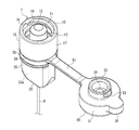
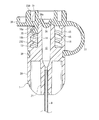
図1Aは本発明の実施形態1に係るキャップ30付きコネクタ(オスコネクタ)1の上方から見た斜視図である。図1Bはキャップ30付きコネクタ1の断面斜視図である。図1Bにおいて、一点鎖線1aは、コネクタ1の中心軸である。コネクタ1は、一方の側に、延長チューブや注入器が接続されるコネクタ本体部10を備え、他方の側に、患者に挿入される経鼻カテーテル9の上流端が接続される基端部20を備える。本発明では、コネクタ1において、コネクタ本体部10の側を「先端側」または「上側」といい、基端部20の側を「基端側」または「下側」という。コネクタ本体部10と基端部20とを結ぶ方向(即ち、中心軸1aに沿った方向)を「上下方向」といい、中心軸1aに垂直な平面に平行な方向を「水平方向」という。中心軸1aに直交する方向を「半径方向」、中心軸1a回りに回転する方向を「周方向」という。但し、「上側」、「下側」、「上下方向」、及び「水平方向」は、コネクタ1の使用時の向きを意味するものではない。
FIG. 1A is a perspective view of the connector (male connector) 1 with a
図1Bに示されているように、コネクタ本体部10は、中心軸1aと同軸のオス部材11及び外筒15を有する。オス部材11は棒状の部材である。流路12が、オス部材11の長手方向に沿ってオス部材11を貫通している。オス部材11の外周面13は、先端に近づくにしたがって外径が小さくなるテーパ面(いわゆるオステーパ面)である。外筒15は中空の円筒形状を有し、オス部材11を取り囲んでいる。外筒15の内周面(オス部材10に対向する面)には雌ネジ16が設けられている。オス部材11と外筒15(特にその雌ネジ16のネジ山)とは半径方向に離間し、両者の間に隙間18が存在している。外筒15の外周面17は、上下方向において外径が一定である円筒面である。コネクタ本体部10は、国際標準化することが検討されている、栄養系の医療機器に関する国際規格ISO80369−3のオスコネクタに準拠していてもよい。
As shown in FIG. 1B, the connector
基端部20は、オス部材11と同軸に設けられた筒状の接続管21を備える。貫通孔22が、中心軸1aに沿って接続管21を貫通している。貫通孔22は、オス部材11の流路12と連通している。貫通孔22内に、経鼻カテーテル9が挿入され固定されている。カテーテル9の接続管21への固定方法は任意であり、例えば接着法を用いることができる。カテーテル9は、制限はなく、例えば公知の任意の経鼻カテーテルに用いられる柔軟なカテーテル(チューブ)を用いうる。
The
接続管21を把持部25が取り囲んでいる。把持部25の外面の水平方向に平行な面に沿った断面形状は長方形である。図1Aに示されているように、把持部25は、当該長方形の長辺を含む平坦な2つの把持面25a(図1Aでは、1つの把持面25aのみが見えている)を有する。作業者は、把持面25aを把持することよりコネクタ1に回転力を加えやすい。
The
基端部20の構成は、本実施形態1に限定されない。但し、カテーテル9をオス部材11の流路12と連通するように固定することができる構成を備えていることが好ましい。把持部25の構成は任意に変更することができる。例えば接続管21に把持面25aが直接設けられていてもよい。あるいは、把持部25及び把持面25aを省略してもよい。
The configuration of the
キャップ30は、バンド37を介してコネクタ1に接続されている。このため、キャップ30を紛失するのを防止できる。また、コネクタ1の非使用時に、キャップ30をコネクタ1の先端に装着する(後述する図3A及び図3B参照)のを忘れる可能性も低い。
The
キャップ30は、円形の天板31を有する。天板31の外径は、キャップ30をコネクタ1の先端に装着したとき(後述する図3A及び図3B参照)、天板31が外筒15の上方に向いた開口を塞ぐことができるように設定される。具体的には、天板31の外径は、外筒15に設けられた雌ネジ16の谷径より大きい。一般には、天板31の外径は、外筒15の外径と略同一か、これよりわずかに大きいことが好ましい。天板31の外周端縁にバンド37が接続されている。バンド37は、半径方向に沿って真っ直ぐに延びる帯状の薄平板である。天板31の外周端縁のうち、バンド37とは反対側の位置から操作タブ36が突出している。
The
天板31の一方の面(図1Aにおいて上方を向いた面)から、円筒形状を有する筒状部(リブ)32が上方に向かって突出している。筒状部32の外周面から突起33が突出している。突起33は、筒状部32に対して操作タブ36と同じ側に配置されている。図1Bに示されているように、突起33は天板31からわずかに離間している。上方から見たとき、中心軸1aに対して、バンド37、天板31、突起33、操作タブ36が半径方向に沿った一直線上に配置される。
A cylindrical portion (rib) 32 having a cylindrical shape projects upward from one surface of the top plate 31 (the surface facing upward in FIG. 1A). The
筒状部32で囲まれた領域内に、栓体34が設けられている。栓体34は、円形の平面視形状を有し、上方に向かって突出している。栓体34は、天板31の近傍に、シール面34aを有する。シール面34aは、外径が一定である円筒面、または、天板31から上方に向かって離間するにしたがって外径が小さくなるオステーパ面(即ち円錐面)である。天板31、筒状部32、栓体34は、同心状に配置されている。筒状部32は、栓体34を取り囲み、且つ、栓体34から離間している。
A
図1A及び図1Bに示すように、コネクタ1の外筒15の先端側(上側)の開口が露出された状態を、本発明では「開状態」という。
As shown in FIGS. 1A and 1B, the state in which the opening on the tip end side (upper side) of the
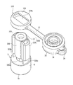
図2は、キャップ30付きコネクタ1の分解斜視図である。バンド37のキャップ30とは反対側端に、円環状のリング38が設けられている。リング38の外周面は、コネクタ1の外筒15と略同一径の円筒面である。リング38の内周面は円筒面であるが、等角度間隔で4つの凹部(切り欠き)38aが設けられている。キャップ30、バンド37、及びリング38は一体化されてキャップ装置39を構成する。
FIG. 2 is an exploded perspective view of the
コネクタ1の外周面であって、コネクタ本体部10と基端部20との間の位置に、周方向に連続する溝28が設けられている。溝28内に、半径方向に沿って外向きに突出する4つの凸部28a(図2では、2つの凸部28aのみが見えている)が中心軸1aに対して等角度間隔で設けられている。
A
図1A及び図1Bに示されているように、リング38が溝28内に嵌入するように、キャップ装置39はコネクタ1に装着される。溝28内の凸部28aがリング38の凹部38aに嵌合する。キャップ30はバンド37を介してリング38に接続されている。このため、キャップ30を含むキャップ装置39は、コネクタ1に対して周方向に回転することができない。即ち、リング38の凹部38a及びバンド37は、キャップ30がコネクタ1の中心軸1a周りに回転するのを制限する「回転制限機構」を構成する。なお、回転制限機構の構成は、本実施形態1に限定されない。例えば、凹部38a及び凸部28aの数や配置は、本実施形態1に限定されず、任意に変更しうる。凹部38a及び凸部28aに代えて、互いに嵌合し合う任意の形状(例えば、多角柱面)を、リング38の内周面及び溝28内に設けてもよい(例えば、後述する実施形態3参照)。回転制限機構は、キャップ30の中心軸1a回りの回転を実質的に制限できればよい。例えば、バンド37が変形することによるキャップ30の周方向の変位は許容される。
As shown in FIGS. 1A and 1B, the
コネクタ1の材料は、制限はないが、外力によって実質的に変形しない程度の機械的強度(剛性)を有する硬い材料(硬質材料)であることが好ましい。例えば、ポリカーボネート(PC)、アクリロニトリル−ブタジエン−スチレン共重合体(ABS)、硬質ポリ塩化ビニル、ポリアセタール(POM)、ポリスチレン、ポリアミド、ポリエチレン、ポリプロピレン(PP)等の樹脂材料を用いることができ、中でもポリカーボネート(PC)、アクリロニトリル−ブタジエン−スチレン共重合体(ABS)、硬質ポリ塩化ビニルが好ましい。コネクタ1は、上記の樹脂材料を用いて、射出成形法等により全体を一部品として一体的に製造することができる。
The material of the
キャップ装置39の材料は、制限はないが、キャップ30のコネクタ本体部10に対する着脱を容易にし、更に、繰り返しの着脱を可能にするために、変形が可能な柔軟性と耐久性を有していることが好ましい。特に、キャップ装置39は、コネクタ1よりも軟質の材料からなることが好ましい。具体的には、ポリプロピレン(PP)、ポリエチレン(PE)等の樹脂材料を用いることができる。あるいは、イソプレンゴム、シリコーンゴム、ブチルゴム等のゴムや、スチレン系エラストマー、オレフィン系エラストマー、ポリウレタン系エラストマー、塩化ビニル系エラストマー等の熱可塑性エラストマーのような、ゴム弾性を有する軟質の材料(いわゆるエラストマー)を用いることができる。キャップ装置39は、上記の材料を用いて、例えば射出成形法等により全体を一部品として一体的に製造することができる。
The material of the
コネクタ1とキャップ装置39とを一体化させる方法は任意である。例えば、コネクタ1及びキャップ装置39を別々に製造し、リング38内にコネクタ1(即ち、コネクタ本体部10または基端部20)を挿入して組み立てることができる(挿入法)。挿入法では、コネクタ本体部10(または基端部20)がリング38を通過する際に、リング38は拡径するように周方向に伸ばされる。従って、キャップ装置39が上述した軟質の材料からなることは、挿入法によりコネクタ1にキャップ装置39を装着するのに有利である。あるいは、二色成形法によりコネクタ1とキャップ装置39とを一体化させてもよい。具体的には、一次金型にてコネクタ1を成形し、二次金型にてキャップ装置39を成形し且つこれをコネクタ1に一体化させることができる。二色成形法は、キャップ装置39の材料が、挿入法では組み立てることが困難な比較的高強度の材料である場合にも使用しうる。
The method of integrating the
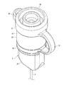
キャップ30は、図3A及び図3Bに示すように、コネクタ1の先端に装着することができる。即ち、天板31の筒状部32が設けられた側の面がオス部材11に対向するようにキャップ30とコネクタ本体部10とを上下方向に対向させて、キャップ30をコネクタ1に向かって押し込む。図3A及び図3Bに示すように、外筒15の先端側(上側)の開口がキャップ30の天板31で塞がれる。この状態を、本発明では「閉状態」という。バンド37は略円弧状に湾曲している。湾曲したバンド37及び操作タブ36は、外筒15の外周面よりも半径方向の外側に向かって互いに反対向きに突出している。
The
カテーテル9は、鼻を経由して、その末端(図示せず)が胃に達するように患者に挿入されている。カテーテル9の上流側端にコネクタ1が取り付けられている。この状態で、カテーテル9及びコネクタ1は患者に留置され続ける。経腸栄養法を行う場合には、キャップ30をコネクタ1の先端から取り外し、コネクタ1を開状態とする(図1A及び図1B参照)。そして、コネクタ本体部10にメスコネクタ(容器側コネクタ)を接続し、液状物を患者に投与する。メスコネクタは、例えば、液状物を貯留した容器に接続されたチューブの下流側端に、または液状物を貯留した注入器(例えばシリンジ)の口部に、設けられている。メスコネクタは、好ましくは雌ネジ16に螺合する雄ネジ(または突起)を有する。メスコネクタは、ISO80369−3に準拠していてもよい。経腸栄養法を終了すると、コネクタ本体部10からメスコネクタを分離し、代わりにキャップ30をコネクタ本体部10の先端に装着し、コネクタ1を閉状態にする(図3A及び図3B参照)。このように、キャップ30は、コネクタ1の先端に対して繰り返し着脱することができる。
The
図3Bに示されているように、閉状態では、キャップ30の筒状部32が、外筒15とオス部材11との間の隙間18に嵌入し、また、キャップ30の栓体34がオス部材11の流路12に嵌入している。更に、キャップ30の天板31が外筒15の上端に当接している。このため、オス部材11の流路12や外筒15とオス部材11との間の隙間18が、キャップ30で塞がれる。経腸栄養法を行わないコネクタ1の非使用時にコネクタ1を閉状態にすることにより、流路12及び隙間18を清潔に保つことができる。
As shown in FIG. 3B, in the closed state, the
図3Bに示されているように、キャップ30の筒状部32から突出した突起33が、外筒15に設けられた雌ネジ16の上下方向に隣り合うネジ山16a,16b間の隙間に嵌入している。突起33が天板31から上下方向に離間しているので、天板31が外筒15の先端に当接した状態で、突起33をネジ山16a,16b間に嵌入させることができる。突起33の先端は、ネジ山16a,16bの先端よりも半径方向の外側に位置している。即ち、突起33は雌ネジ16(特にそのネジ山16a)に係合している。
As shown in FIG. 3B, the
図1A及び図1Bに示した開状態から図3A及び図3Bに示す閉状態へ至る過程で、突起33は雌ネジ16のネジ山16aを乗り越える必要がある。突起33はネジ山16aを乗り越える際に変形し、ネジ山16aを乗り越えた直後に直ちに元の形状に復帰する。作業者がキャップ30をコネクタ1に向かって押し込む力は、突起33がネジ山16aを乗り越える際に急激に増加し、ネジ山16aを乗り越えた直後に急激に減小する。作業者は、このような力の変化をクリック感として感じ取り、これにより、キャップ30がコネクタ1の先端に適切に装着されたと認識する。従って、キャップ30をコネクタ1に常に適切に装着することができる。筒状部32は円筒形状を有するので、比較的大きな強度を有する。このような筒状部32に突起33が設けられているので、キャップ30をコネクタ1に装着したときに、突起33は雌ネジ16のネジ山16aを確実に乗り越えることができる。
In the process from the open state shown in FIGS. 1A and 1B to the closed state shown in FIGS. 3A and 3B, the
キャップ30をコネクタ1を装着した後は、図3Bに示されているように、突起33は雌ネジ16のネジ山16aに係合する。キャップ30をコネクタ1から取り外すためには、突起33はネジ山16aを乗り越える必要があり、この際、突起33を変形させなければならない。キャップ30をコネクタ1から取り外すためには大きな力が必要である。このため、キャップ30がコネクタ1から意図せずに脱落する可能性は低い。雌ネジ16に係合する突起33はキャップ30のコネクタ1に対する装着強度を向上させるのに有利である。上述したように、患者の胃の内圧が上昇することにより流路12の圧力が上昇することがある。閉状態のコネクタ1を患者に留置した状態で流路12の圧力が上昇しても、キャップ30がコネクタ1から抜け出る可能性は低い。また、操作タブ36や天板31等に誤って上向きに力が加えられても、キャップ30がコネクタ1から意図せずに外れる可能性は低い。
After attaching the
本実施形態1とは異なり、突起33を用いないで、キャップ30のコネクタ1に対する装着強度を向上させることは可能である。
Unlike the first embodiment, it is possible to improve the mounting strength of the
例えば、筒状部32の上下方向寸法を大きくして、筒状部32とオス部材11(または外筒15)との嵌合深さを増大させた場合にも、キャップ30の装着強度を向上させることは可能である。しかしながら、筒状部32の上下方向寸法を大きくした場合、キャップ30をコネクタ1に着脱する際にキャップ30をコネクタ1に対して上下方向に長距離移動させる必要がある。これは、キャップ30の着脱の作業性を低下させる。また、バンド37を長くする必要があるので、キャップ30をコネクタ1に装着した状態でのバンド37の半径方向に沿った突出量(図3A及び図3B参照)が増大する。その結果、キャップ30が装着されたコネクタ1が患者の体や顔の下敷きになった場合に、大きく突出したバンド37によって患者が痛みを感じる可能性が高い。
For example, even when the vertical dimension of the
あるいは、天板31の外周端縁に、筒状部32と同じ側に向かって突出する円筒状のリブを設け、キャップ30をコネクタ1に装着したとき、外筒15の先端部分が当該円筒状リブに嵌入するように構成することができる。この場合、例えば、円筒状リブの内周面と外筒15の外周面とに、互いに係合し合う係合構造(例えば、凸部と、当該凸部が嵌入する凹部)を設けることができる。この構成も、突起33を用いないで、キャップ30のコネクタ1に対する装着強度を向上させることは可能である。しかしながら、この構成では、キャップ30(特に天板31)の外径を大きくする必要がある。その結果、キャップ30が装着されたコネクタ1が患者の体や顔の下敷きになった場合に、半径方向に大きく突出した天板31によって患者が痛みを感じる可能性が高い。
Alternatively, when a cylindrical rib projecting toward the same side as the
上記の説明から分かるように、本実施形態1のように、雌ネジ16に係合する突起33をキャップ30に設けた構成は、キャップ30のコネクタ1に対する装着強度を確保しながら、キャップ30の着脱の作業性を向上させ、且つ、キャップ30を小型化するのに有利である。コネクタ1に設けられた雌ネジ16を利用するので、キャップ30の装着強度を向上させるために、コネクタ1の構成を変更する必要がない。
As can be seen from the above description, in the configuration in which the
図3Bに示されているように、キャップ30をコネクタ1を装着したとき、好ましくは、突起33は、雌ネジ16のネジ山16a,16bから上下方向に離間している。突起33は、雌ネジ16から力を受けることはなく、変形することもない。従って、コネクタ1が閉状態で長期間にわたって患者に留置されても、突起33が雌ネジ16に接触することによって永久変形してしまうという事態を回避できる。これは、突起33による上記の作用を長期にわたって衰えることなく奏させるのに有利である。
As shown in FIG. 3B, when the
本実施形態1では、リング38の内周面に設けられた凹部38aが、コネクタ1の溝28内に設けられた凸部28aに嵌合し(図2参照)、且つ、キャップ30はバンド37を介してリング38に接続されているので、コネクタ1に対するキャップ30の中心軸1a回りの回転方向の位置は経時的に変化せず、実質的に一定である。このため、コネクタ1に対するキャップ30の着脱を繰り返すなど、キャップ30に様々な外力が作用しても、常に、突起33を、雌ネジ16の上下方向に隣り合うネジ山16a、16b間に、これらから上下方向に離間して嵌入させることができる。
In the first embodiment, the
好ましくは、筒状部32の内径は、オス部材11の外周面13の外径よりわずかに小さく設定される。これにより、筒状部32内にオス部材11が挿入されると、筒状部32がわずかに拡径するように変形される。筒状部32の内周面とオス部材11の外周面13とは面接触し、両者間に液密なシールが形成される。これは、流路12の封止性の向上と、キャップ30のコネクタ1に対する装着強度の向上に有利である。更に、筒状部32が拡径されることによって、突起33は雌ネジ16の溝により深く挿入される。これは、突起33と雌ネジ16との係合深さを増大させるので、キャップ30のコネクタ1に対する装着強度の向上に有利である。
Preferably, the inner diameter of the
本実施形態1では、キャップ30をコネクタ1に装着したとき、筒状部32と外筒15に設けられた雌ネジ16とは半径方向に離間している。但し、本発明ではこれは必須ではない。例えば、キャップ30をコネクタ1に装着したとき、筒状部32と外筒15に設けられた雌ネジ16とが半径方向に当接してもよい。これは、キャップ30のコネクタ1に対する装着強度の更なる向上に有利でありうる。
In the first embodiment, when the
図3A及び図3Bに示した閉状態においてキャップ30をコネクタ1から取り外すためには、操作タブ36を上方に持ち上げればよい。突起33は筒状部32に対して操作タブ36と同じ側に設けられているので(図1A及び図2参照)、操作タブ36と突起33とは接近している。このため、操作タブ36を持ち上げると、突起33も上方に移動させることができるので、キャップ30の取り外し作業が容易である。
In order to remove the
栓体34が、オス部材11の流路12の先端側の開口に嵌入している。これは、キャップ30のコネクタ1に対する装着強度の向上に有利である。好ましくは、栓体34は、流路12を液密に封止する。栓体34で流路12を封止することは、胃の内圧上昇により流路12の圧力が上昇したときに、キャップ30がコネクタ1から脱落する可能性を低減するのに有利である。その理由は、以下のとおりである。
The
本実施形態1とは異なり、栓体34を用いないで、流路12を封止することは可能である。例えば、栓体34を省略して、筒状部32の内周面とオス部材11の外周面13との間に形成されるシールによって、流路12を間接的に封止することができる。
Unlike the first embodiment, it is possible to seal the
流路12の圧力が上昇したときにキャップ30が受ける上向きの力は、圧力が作用する面積に比例する。流路12を栓体34で封止する本実施形態1の構成は、栓体34を用いずに筒状部32とオス部材11との間のシールで封止する構成に比べて、圧力が作用する面積が小さいので、流路12の圧力が上昇したときにキャップ30が受ける力は小さい。このため、本実施形態1では、流路12の圧力上昇時にキャップ30がコネクタ1から脱落するのを防止するのに有利となる。
The upward force received by the
更に、本実施形態1では、栓体34の外周面を構成するシール面34aが、オス部材11の流路12を規定する内周面(特に流路12の先端側開口近傍の内周面)に嵌合し、両者間に液密なシールが形成される。即ち、シール面34aと流路12を規定する内周面とが、略半径方向に密着してシールを形成する。この構成では、栓体34がオス部材11に対して中心軸1a方向にわずかに位置ズレしても、液密なシールを形成し続けることが可能である。例えば、キャップ30をコネクタ1に装着したときのキャップ30のコネクタ1への押し込み深さがわずかに浅い場合や、流路12の圧力上昇によってキャップ30がコネクタ1から上方にわずかに浮き上がった場合でも、流路12を封止し続けることができる。このため、本実施形態1は、胃の内容物の逆流等の防止に有利である。
Further, in the first embodiment, the
本実施形態1では、キャップ30は、オス部材11の流路12を封止するのみならず、その天板31が、外筒15の先端側の開口をも塞ぐ。このため、外筒15とオス部材11との間の隙間18を清潔に保つことができる。オス部材11の外周面13と外筒15の雌ネジ16との間の間隔は非常に狭いので、例えば綿棒等を挿入して隙間18を清掃することは困難である。隙間18の衛生状態が悪いと、隙間18内で菌が繁殖し、当該菌が流路12を通じて患者の体内に侵入する可能性がある。本実施形態1のキャップ30は、外筒15の先端側の開口を塞ぐので、コネクタ1が患者に長期間にわたって留置されても、隙間18を清潔に保つことができ、菌が患者に侵入して重症な合併症を引き起こす事態の発生を防止することができる。
In the first embodiment, the
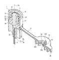
(実施形態2)
図4Aは本発明の実施形態2に係るキャップ230付きコネクタ(オスコネクタ)1の上方から見た斜視図である。図4Bはキャップ230付きコネクタ1の断面斜視図である。本実施形態2は、雌ネジ16に係合する突起33が設けられるリブの形状に関して実施形態1と異なる。以下、実施形態1と異なる点を中心に、本実施形態2を説明する。(Embodiment 2)
FIG. 4A is a perspective view of the connector (male connector) 1 with a
本実施形態2では、突起33は、天板31の面(図4Aにおいて上方を向いた面)から突出した略板状のリブ232の側面に設けられている。上方から見たとき、リブ232は、略円弧に沿っている。即ち、リブ232は、円筒形状の一部をなす。この円筒形状は、実施形態1の筒状部32を構成する円筒形状と同じである。
In the second embodiment, the
図5は、コネクタ1の先端にキャップ230を装着した状態を示した断面図である。リブ232が、外筒15とオス部材11との間の隙間18に嵌入し、また、突起33が雌ネジ16に係合している。
FIG. 5 is a cross-sectional view showing a state in which the
栓体34が、オス部材11の流路12の先端側の開口に嵌入している。このため、キャップ230が、コネクタ1に対して水平方向に位置決めされる。これは、突起33を雌ネジ16に確実に係合させるのに有利である。また、リブ232の、突起33とは反対側の面(栓体34側の面)が、オス部材11の外周面13に当接している。これも、突起33を雌ネジ16に確実に係合させるのに有利である。
The
本実施形態2は、上記を除いて実施形態1と同じである。実施形態1の説明が本実施形態2に適宜適用されうる。 The second embodiment is the same as the first embodiment except for the above. The description of the first embodiment may be appropriately applied to the second embodiment.
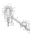
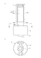
(実施形態3)
図6Aは、本発明の実施形態3に係るキャップ30付きコネクタ(オスコネクタ)3の接続管21側から見た斜視図である。図6Bは、キャップ30付きコネクタ3の断面図である。図7は、キャップ30付きコネクタ3の分解斜視図である。図8Aはコネクタ3の側面図、図8Bは図8Aの8B−8B線を含む面に沿ったコネクタ3の矢視断面図である。図9は、キャップ30を含む、本発明の実施形態3に係るキャップ装置339の斜視図である。(Embodiment 3)
FIG. 6A is a perspective view of the connector (male connector) 3 with a
図7及び図9に最もよく示されているように、本実施形態3のキャップ装置339のリング338には略長方形の貫通孔338aが形成されている。貫通孔338aの内径は、リング338の厚さ方向に一定ではない。図9に示されているように、筒状部32が形成された面と同じ側の面に向かって内径が大きくなるように傾斜した傾斜面338bが、貫通孔338aの内周面に形成されている。
As best shown in FIGS. 7 and 9, a substantially rectangular through
図7に示されているように、基端部320は、略円筒形状の接続管21を備える。接続管21の外周面に、一対の把持片326が半径方向に突出するように設けられている。各把持片326の水平方向に沿った断面形状は、中空の略「U」字形状である。一対の把持片326とその間の接続管21とが、コネクタ3の把持部325を構成する。把持部325は、実施形態1の把持部25と同様に、作業者が把持部325を把持してコネクタ3に回転力を加えるのを容易にする。把持片326の構成は、本実施形態3に限定されない。例えば、把持片326が中実の略四角柱体であってもよく、あるいは、接続管21から半径方向に沿って延びた薄い板状物であってもよい。
As shown in FIG. 7, the
接続管21及び把持片326の半径方向の外側を向いた面の、コネクタ本体部10に隣接する位置に、溝328a及び溝328bが設けられている。溝328a,328bは、水平方向に沿っている。図8Bは溝328a,328bを通る面に沿ったコネクタ3の断面図である。図8Bに示すコネクタ3の断面形状は、リング338に設けられた貫通孔338a(図7参照)を規定する略長方形の端縁に内接するように構成されている。
キャップ装置339は、図7に示すようにリング338に基端部320を挿入することにより、コネクタ3に装着される。接続管21及び把持片326が貫通孔338aに挿入される際に、貫通孔338aの内周面に形成された傾斜面338b(図9参照)が、貫通孔338aの内径が拡大するようにリング338を変形させる。従って、リング338に対するコネクタ3(特に基端部320)の挿入が容易である。貫通孔338aの端縁が溝328a,328bに到達すると、リング338は変形前の状態に復帰し、図6A及び図6Bに示すように貫通孔338aの端縁が溝328a,328bに嵌入する。
The
溝328a,328bでのコネクタ3の断面形状がリング338の略長方形の貫通孔338aに嵌合する。このため、コネクタ3に対するリング338の回転が制限される。リング338に設けられた貫通孔338a、及び、リング338とキャップ30とをつなぐバンド37が、キャップ30がコネクタ3の中心軸周りに回転するのを制限する「回転制限機構」を構成する。
The cross-sectional shape of the
本実施形態3は、上記を除いて実施形態1と同じである。実施形態1の説明が本実施形態3に適宜適用されうる。リング338に設けられた傾斜面338bと同様に、内径が厚さ方向において変化するように傾斜した傾斜面を、実施形態1のリング38の内周面に設けて、挿入法によるキャップ30付きコネクタ1の組立を容易にしてもよい。
The third embodiment is the same as the first embodiment except for the above. The description of the first embodiment may be appropriately applied to the third embodiment. Similar to the
本実施形態3の上記の構成を、実施形態2に適用することができる。 The above configuration of the third embodiment can be applied to the second embodiment.
上記の実施形態1〜3は例示に過ぎない。本発明は、上記の実施形態1〜3に限定されず、適宜変更することができる。
The
雌ネジ16に係合する突起33が設けられるリブが、実施形態1,3では円筒形状を有する筒状部32であり、実施形態2では円筒形状の一部をなすリブ232であったが、本発明はこれに限定されない。リブは、キャップをコネクタに装着したとき、コネクタの外筒15内に挿入することができるように構成される限り、任意の形状を有していてもよい。例えば、リブは、平板状、柱状(または棒状)等の任意の形状を有していてもよい。リブは、天板31の一方の面から略垂直に立設される。天板31に複数のリブが設けられていてもよい。例えば、複数のリブが、外筒15と同心の円上に離散的に配置されていてもよい。
The rib provided with the
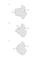
キャップに設けられる突起33の形状は任意である。キャップ(または栓体34)の中心軸を含む面に沿った突起33の断面形状は、図10Aに示すような台形、図10Bに示すような三角形、図10Cに示すような半円形などのいずれであってもよく、あるいは、これら以外の任意の形状であってもよい。突起33の長さ(キャップの中心軸回りに回転する方向に沿った寸法)も任意である。突起33が、雌ネジ16の溝と合致する螺旋に沿って延びていていもよい。
The shape of the
突起33の数は、1つに限定されず、2つ以上であってもよい。2つ以上の突起33のリブ32,230上の位置は任意である。2つ以上の突起33の上下方向位置及び周方向位置のうちの一方が一致していてもよい。キャップに複数のリブが設けられる場合、複数のリブの全てに1つ以上の突起33が設けられていてもよいし、複数のリブのうちの一部のリブのみに1つ以上の突起33が設けられていてもよい。
The number of
キャップ装置39,339をコネクタに固定するための構成は、リング38,338に限定されない。例えば、リング38,338に代えて、バンド37の先端に略「T」字形状(または略「Y」字形状)を有する固定部を設けてもよい。この固定部は、コネクタに嵌入または埋設される。この構成でも、上記の実施形態と同様に、キャップ装置を、キャップが周方向に回転するのを制限しながらコネクタに固定することができる。
The configuration for fixing the
キャップがコネクタに対して回転するのを制限する回転制限機構を省略してもよい。例えば、実施形態1において凹部38a及び凸部28aの一方または両方を省略し、リング38が、コネクタ1に対して中心軸1a周りに自由に回転可能に溝28に嵌入されていてもよい。この場合、突起33が雌ネジ16の溝内を移動するようにキャップをコネクタに対して回転させることによって、キャップのコネクタ1に対する着脱作業を行うこともできる。この構成は、突起33を雌ネジ16により深く係合させることができるので、キャップのコネクタ1に対する装着強度を向上させるに有利でありうる。また、バンド37を短くするのに有利でありうる。
The rotation limiting mechanism that limits the rotation of the cap with respect to the connector may be omitted. For example, in the first embodiment, one or both of the
上記の実施形態1〜3では、キャップをコネクタの先端に装着したとき、バンド37は円弧状に湾曲したが、バンド37の構成はこれに限定されない。例えば、バンド37、バンド37とキャップとの境界部、バンド37とリング38,338との境界部のうちの少なくとも一つに、自由に回動可能なヒンジが設けられていてもよい。キャップをコネクタに着脱するとき、ヒンジ以外ではバンド37は実質的に変形しない。この構成は、コネクタが閉状態でのバンド37の半径方向に沿った突出量を少なくするのに有利でありうる。
In the above-described first to third embodiments, when the cap is attached to the tip of the connector, the
本発明では、バンド37を省略し、キャップがコネクタから分離された部品であってもよい。
In the present invention, the
操作タブ36の形状や数、位置等は、上記の実施形態1〜3に限定されず、任意に変更しうる。操作タブ36が、天板31から筒状部32とは反対側に向かって突出していてもよい。あるいは、操作タブ36を省略してもよい。例えば、天板31が外筒15から半径方向に突出するように、キャップの天板31の外径を、コネクタの外筒15の外径よりわずかに大きくすれば、操作タブ36がなくてもキャップをコネクタから取り外すことが可能である。
The shape, number, position, etc. of the
上記の実施形態1〜3では、コネクタが経鼻カテーテル9の上流端に設けられる場合を説明したが、コネクタは、経鼻カテーテル以外の経腸栄養法で用いられる任意のカテーテル(例えば、PEGカテーテル)の上流端に設けることができる。また、経腸栄養法以外の、例えば静脈栄養法に用いられるチューブに設けることもできる。
In the
上記の実施形態ではコネクタ本体部10は、ISO80369−3に準拠したオスコネクタであったが、本発明はこれに限定されない。本発明のキャップは、雌ネジが設けられた外筒を有する任意のコネクタに適用できる。コネクタはオス部材11を備えていなくてもよい。コネクタがメスコネクタであってもよい。
In the above embodiment, the connector
本発明のキャップは、制限はないが、カテーテルやチューブの一端に設けられるコネクタ用のキャップとして利用することができる。当該コネクタの利用分野は制限はなく、食品や化学の分野で利用されるものであってもよいが、医療分野、更には経腸栄養法で使用されるものであることが好ましい。特に、本発明は、経鼻カテーテルやPEGカテーテルのように患者の体内に挿入されたカテーテルの上流側端に固定され、当該カテーテルとともに長期間にわたって患者に留置され続けるコネクタ用のキャップとして利用されることが好ましい。 The cap of the present invention is not limited, but can be used as a cap for a connector provided at one end of a catheter or a tube. The field of use of the connector is not limited and may be used in the fields of food and chemistry, but it is preferably used in the medical field and further in the enteral nutrition method. In particular, the present invention is used as a cap for a connector that is fixed to the upstream end of a catheter inserted into a patient's body, such as a nasal catheter or a PEG catheter, and is kept in the patient for a long period of time together with the catheter. Is preferable.
1,3 コネクタ
11 オス部材
12 オス部材の流路
13 オス部材の外周面
15 外筒
16 雌ネジ
16a,16b 雌ネジのネジ山
30 キャップ
31 天板
32 筒状部(リブ)
33 突起
34 栓体
34a シール面(栓体の外周面)
36 操作タブ
37 バンド(回転制限機構)
38,338 リング
38a 凹部(回転制限機構)
230 キャップ
232 リブ
338a 貫通孔(回転制限機構)
338b 傾斜面1,3
33
36
38,338
338b slope
Claims (24)
前記外筒の開口を塞ぐことができるように構成された天板と、
前記天板に設けられ且つ前記外筒に挿入することができるように構成されたリブと、
前記リブの側面から突出した突起とを備え、
前記突起は、前記雌ネジに係合することができるように、前記天板から離間して設けられており、
前記キャップを前記コネクタに装着したとき、前記突起は、前記雌ネジの先端から一つ目のネジ山と二つ目のネジ山との間の隙間に嵌入することを特徴とするコネクタ用キャップ。 A connector cap that can be attached to and detached from a connector having a female screw provided on the inner peripheral surface of an outer cylinder having a cylindrical shape.
A top plate configured to close the opening of the outer cylinder,
Ribs provided on the top plate and configured to be inserted into the outer cylinder,
With a protrusion protruding from the side surface of the rib,
The protrusion is provided apart from the top plate so that it can be engaged with the female screw .
When the cap is attached to the connector, the protrusion is fitted into a gap between the first thread and the second thread from the tip of the female screw .
前記リングの内周面には、内径が前記リングの厚さ方向において変化するように傾斜した傾斜面が設けられている請求項4に記載のコネクタ用キャップ。The connector cap according to claim 4, wherein an inclined surface is provided on the inner peripheral surface of the ring so that the inner diameter changes in the thickness direction of the ring.
前記外筒の開口を塞ぐことができるように構成された天板と、
前記天板に設けられ且つ前記外筒に挿入することができるように構成されたリブと、
前記リブの側面から突出した突起とを備え、
前記突起は、前記雌ネジに係合することができるように、前記天板から離間して設けられており、
前記キャップを前記コネクタに装着したとき、前記突起は前記雌ネジを構成するネジ山から離間することを特徴とするコネクタ用キャップ。 A connector cap that can be attached to and detached from a connector having a female screw provided on the inner peripheral surface of an outer cylinder having a cylindrical shape.
A top plate configured to close the opening of the outer cylinder,
Ribs provided on the top plate and configured to be inserted into the outer cylinder,
With a protrusion protruding from the side surface of the rib,
The protrusion is provided apart from the top plate so that it can be engaged with the female screw.
When mounting the cap on the connector, said protrusions connector cap, characterized in that spaced from threads constituting the female screw.
前記リングの内周面には、内径が前記リングの厚さ方向において変化するように傾斜した傾斜面が設けられている請求項8に記載のコネクタ用キャップ。The connector cap according to claim 8, wherein the inner peripheral surface of the ring is provided with an inclined surface whose inner diameter is inclined so as to change in the thickness direction of the ring.
前記外筒の開口を塞ぐことができるように構成された天板と、
前記天板に設けられ且つ前記外筒に挿入することができるように構成されたリブと、
前記リブの側面から突出した突起とを備え、
前記突起は、前記雌ネジに係合することができるように、前記天板から離間して設けられており、
前記キャップは、前記コネクタの中心軸周りに前記キャップが回転するのを制限する回転制限機構を更に備えることを特徴とするコネクタ用キャップ。 A connector cap that can be attached to and detached from a connector having a female screw provided on the inner peripheral surface of an outer cylinder having a cylindrical shape.
A top plate configured to close the opening of the outer cylinder,
Ribs provided on the top plate and configured to be inserted into the outer cylinder,
With a protrusion protruding from the side surface of the rib,
The protrusion is provided apart from the top plate so that it can be engaged with the female screw.
The cap is a connector cap, further comprising a rotation limiting mechanism that limits the rotation of the cap around the central axis of the connector.
前記リングの内周面には、内径が前記リングの厚さ方向において変化するように傾斜した傾斜面が設けられている請求項12に記載のコネクタ用キャップ。The connector cap according to claim 12, wherein an inclined surface is provided on the inner peripheral surface of the ring so that the inner diameter changes in the thickness direction of the ring.
前記外筒の開口を塞ぐことができるように構成された天板と、
前記天板に設けられ且つ前記外筒に挿入することができるように構成されたリブと、
前記リブの側面から突出した突起とを備え、
前記突起は、前記雌ネジに係合することができるように、前記天板から離間して設けられており、
前記キャップは、前記キャップを前記コネクタに接続するためのバンドを更に備え、
前記バンドの前記キャップとは反対側端に、環状のリングが設けられており、
前記リングの内周面には、内径が前記リングの厚さ方向において変化するように傾斜した傾斜面が設けられていることを特徴とするコネクタ用キャップ。 A connector cap that can be attached to and detached from a connector having a female screw provided on the inner peripheral surface of an outer cylinder having a cylindrical shape.
A top plate configured to close the opening of the outer cylinder,
Ribs provided on the top plate and configured to be inserted into the outer cylinder,
With a protrusion protruding from the side surface of the rib,
The protrusion is provided apart from the top plate so that it can be engaged with the female screw.
The cap further comprises a band for connecting the cap to the connector.
An annular ring is provided at the end of the band opposite to the cap.
A connector cap characterized in that the inner peripheral surface of the ring is provided with an inclined surface whose inner diameter changes in the thickness direction of the ring.
前記オス部材の長手方向に沿って前記オス部材を貫通する流路が、前記オス部材の先端において開口しており、
前記筒状部は、前記キャップを前記コネクタに装着したとき、前記筒状部の内周面と前記オス部材の外周面との間に液密なシールが形成されるように構成されている請求項17に記載のコネクタ用キャップ。 The connector includes a male member coaxially provided with the outer cylinder so as to be surrounded by the outer cylinder.
A flow path penetrating the male member along the longitudinal direction of the male member is open at the tip of the male member.
The tubular portion is configured so that when the cap is attached to the connector, a liquid-tight seal is formed between the inner peripheral surface of the tubular portion and the outer peripheral surface of the male member. Item 17. The connector cap according to item 17.
前記オス部材の長手方向に沿って前記オス部材を貫通する流路が、前記オス部材の先端において開口しており、
前記キャップは、前記流路の開口に嵌入するように構成された栓体を更に備える請求項1〜18のいずれか一項に記載のコネクタ用キャップ。 The connector includes a male member coaxially provided with the outer cylinder so as to be surrounded by the outer cylinder.
A flow path penetrating the male member along the longitudinal direction of the male member is open at the tip of the male member.
The connector cap according to any one of claims 1 to 18 , further comprising a plug body configured to fit into the opening of the flow path.
前記操作タブは前記リブに対して前記突起と同じ側に配置されている請求項1〜21のいずれか一項に記載のコネクタ用キャップ。 Further provided with an operation tab protruding from the outer peripheral edge of the top plate,
The connector cap according to any one of claims 1 to 21 , wherein the operation tab is arranged on the same side as the protrusion with respect to the rib.
Applications Claiming Priority (3)
| Application Number | Priority Date | Filing Date | Title |
|---|---|---|---|
| JP2016128968 | 2016-06-29 | ||
| JP2016128968 | 2016-06-29 | ||
| PCT/JP2017/023953 WO2018003923A1 (en) | 2016-06-29 | 2017-06-29 | Cap for connector, and connector with cap |
Publications (2)
| Publication Number | Publication Date |
|---|---|
| JPWO2018003923A1 JPWO2018003923A1 (en) | 2019-04-25 |
| JP6908040B2 true JP6908040B2 (en) | 2021-07-21 |
Family
ID=60787295
Family Applications (1)
| Application Number | Title | Priority Date | Filing Date |
|---|---|---|---|
| JP2018525262A Active JP6908040B2 (en) | 2016-06-29 | 2017-06-29 | Connector cap and connector with cap |
Country Status (4)
| Country | Link |
|---|---|
| JP (1) | JP6908040B2 (en) |
| KR (1) | KR102349983B1 (en) |
| CN (2) | CN109328087B (en) |
| WO (1) | WO2018003923A1 (en) |
Families Citing this family (12)
| Publication number | Priority date | Publication date | Assignee | Title |
|---|---|---|---|---|
| JP7818351B2 (en) * | 2018-10-17 | 2026-02-20 | ニプロ株式会社 | Female Connector |
| JP7155050B2 (en) * | 2019-03-11 | 2022-10-18 | テルモ株式会社 | Pedestal and protective cap assembly |
| JP7114512B2 (en) * | 2019-03-11 | 2022-08-08 | テルモ株式会社 | Pedestal and protective cap assembly |
| CN111282075A (en) * | 2019-07-22 | 2020-06-16 | 首都儿科研究所 | Infusion connects protective cap |
| JP7508819B2 (en) * | 2020-03-19 | 2024-07-02 | ニプロ株式会社 | Male connector for enteral nutrition |
| CA3198353A1 (en) | 2020-10-09 | 2022-04-14 | Icu Medical, Inc. | Fluid transfer device and method of use for same |
| WO2022085594A1 (en) * | 2020-10-22 | 2022-04-28 | 株式会社ジェイ・エム・エス | Cover for male connector |
| JP7724123B2 (en) * | 2020-10-22 | 2025-08-15 | 株式会社ジェイ・エム・エス | Male connector cover |
| JP2022146557A (en) * | 2021-03-22 | 2022-10-05 | 株式会社トップ | cap |
| DE102022101151A1 (en) | 2022-01-19 | 2023-07-20 | B. Braun Melsungen Aktiengesellschaft | Cap for an enteral conduction set connector and conduction set with a cap |
| JP2025136041A (en) * | 2024-03-06 | 2025-09-19 | 株式会社ジェイ・エム・エス | Medical Catheters |
| JP2025140532A (en) * | 2024-03-14 | 2025-09-29 | 日機装株式会社 | Cap, connector and device |
Family Cites Families (11)
| Publication number | Priority date | Publication date | Assignee | Title |
|---|---|---|---|---|
| HUP0104076A3 (en) * | 1998-10-06 | 2004-04-28 | Arno Sa | Safety system to prevent the functioning of a blender or food processor if the top its cup is not in place |
| JP2006149576A (en) * | 2004-11-26 | 2006-06-15 | Hakko Co Ltd | Medical connector |
| WO2008152871A1 (en) | 2007-06-08 | 2008-12-18 | Jms Co., Ltd. | Female connector and connector |
| JP5304073B2 (en) | 2008-07-17 | 2013-10-02 | ニプロ株式会社 | Medical connector |
| EP2545956A1 (en) * | 2011-07-15 | 2013-01-16 | Becton Dickinson France | Drug delivery device and adaptor |
| JP6164807B2 (en) * | 2012-07-30 | 2017-07-19 | 株式会社トップ | Connector cover |
| WO2014132293A1 (en) * | 2013-02-28 | 2014-09-04 | テルモ株式会社 | Cap |
| JP6151614B2 (en) * | 2013-09-12 | 2017-06-21 | 日機装株式会社 | Connector with medical cap |
| DE102014103508B4 (en) * | 2014-03-14 | 2019-04-18 | Fresenius Medical Care Deutschland Gmbh | Tensioned valve for medical functional device, and medical functional device |
| WO2016089869A1 (en) * | 2014-12-02 | 2016-06-09 | Covidien Lp | Adapter assembly for enteral feeding and method of making |
| CN204319409U (en) * | 2014-12-19 | 2015-05-13 | 江西科伦医疗器械制造有限公司 | A kind of for only liquid transfusion device pipeline emptying |
-
2017
- 2017-06-29 CN CN201780039699.4A patent/CN109328087B/en active Active
- 2017-06-29 JP JP2018525262A patent/JP6908040B2/en active Active
- 2017-06-29 WO PCT/JP2017/023953 patent/WO2018003923A1/en not_active Ceased
- 2017-06-29 CN CN202210385923.8A patent/CN114732736B/en active Active
- 2017-06-29 KR KR1020187036576A patent/KR102349983B1/en active Active
Also Published As
| Publication number | Publication date |
|---|---|
| CN109328087B (en) | 2022-09-20 |
| CN109328087A (en) | 2019-02-12 |
| CN114732736A (en) | 2022-07-12 |
| KR20190022530A (en) | 2019-03-06 |
| JPWO2018003923A1 (en) | 2019-04-25 |
| WO2018003923A1 (en) | 2018-01-04 |
| KR102349983B1 (en) | 2022-01-11 |
| CN114732736B (en) | 2025-04-08 |
Similar Documents
| Publication | Publication Date | Title |
|---|---|---|
| JP6908040B2 (en) | Connector cap and connector with cap | |
| EP3248640B1 (en) | Medical liquid-collection injector | |
| JP2015051092A (en) | Double male connector | |
| JP6919794B2 (en) | Female connector | |
| JP2016158656A (en) | Connector with cap | |
| JP4621029B2 (en) | connector | |
| WO2016035788A1 (en) | Adapter for semi-solid nutritional supplement | |
| KR102507582B1 (en) | Medical Infusion Tip, Infusion Nozzle, and Injector Set | |
| JP7077016B2 (en) | cap | |
| JP5691648B2 (en) | Female connector | |
| JP2018027177A (en) | Male connector disassembling tool and male connector | |
| JP6878788B2 (en) | Cover for male connector | |
| JP6268877B2 (en) | Medical connector | |
| WO2017104689A1 (en) | Female connector | |
| HK40073417A (en) | Cap for connector, and connector with cap | |
| JP6369092B2 (en) | Catheter connector | |
| JP2015051094A (en) | Double female connector | |
| HK40073417B (en) | Cap for connector, and connector with cap | |
| JP2012232019A (en) | Female connector, and connector | |
| JP2010126250A (en) | Female connector, and connecting device | |
| JP2019076480A (en) | Connector | |
| EP4212143B1 (en) | Connector assembly for medical injection device | |
| EP4212142A1 (en) | Vial adaptor providing audible feedback and connector assembly for medical injection device including vial adaptor | |
| JP2022068838A (en) | Cover for male connector | |
| JP2012152418A (en) | Female connector and connecting implement |
Legal Events
| Date | Code | Title | Description |
|---|---|---|---|
| A621 | Written request for application examination |
Free format text: JAPANESE INTERMEDIATE CODE: A621 Effective date: 20200420 |
|
| A131 | Notification of reasons for refusal |
Free format text: JAPANESE INTERMEDIATE CODE: A131 Effective date: 20210105 |
|
| A521 | Request for written amendment filed |
Free format text: JAPANESE INTERMEDIATE CODE: A523 Effective date: 20210219 |
|
| TRDD | Decision of grant or rejection written | ||
| A01 | Written decision to grant a patent or to grant a registration (utility model) |
Free format text: JAPANESE INTERMEDIATE CODE: A01 Effective date: 20210601 |
|
| A61 | First payment of annual fees (during grant procedure) |
Free format text: JAPANESE INTERMEDIATE CODE: A61 Effective date: 20210614 |
|
| R150 | Certificate of patent or registration of utility model |
Ref document number: 6908040 Country of ref document: JP Free format text: JAPANESE INTERMEDIATE CODE: R150 |
|
| R250 | Receipt of annual fees |
Free format text: JAPANESE INTERMEDIATE CODE: R250 |
|
| R250 | Receipt of annual fees |
Free format text: JAPANESE INTERMEDIATE CODE: R250 |