JP6889618B2 - Heat exchanger - Google Patents
Heat exchanger Download PDFInfo
- Publication number
- JP6889618B2 JP6889618B2 JP2017110324A JP2017110324A JP6889618B2 JP 6889618 B2 JP6889618 B2 JP 6889618B2 JP 2017110324 A JP2017110324 A JP 2017110324A JP 2017110324 A JP2017110324 A JP 2017110324A JP 6889618 B2 JP6889618 B2 JP 6889618B2
- Authority
- JP
- Japan
- Prior art keywords
- header
- primary
- flow path
- end side
- merging
- Prior art date
- Legal status (The legal status is an assumption and is not a legal conclusion. Google has not performed a legal analysis and makes no representation as to the accuracy of the status listed.)
- Active
Links
- 238000003780 insertion Methods 0.000 claims description 32
- 230000037431 insertion Effects 0.000 claims description 32
- 238000004891 communication Methods 0.000 claims description 20
- 230000001105 regulatory effect Effects 0.000 claims description 8
- 230000000149 penetrating effect Effects 0.000 claims description 5
- 238000007789 sealing Methods 0.000 claims 2
- 239000003507 refrigerant Substances 0.000 description 98
- 239000012267 brine Substances 0.000 description 57
- HPALAKNZSZLMCH-UHFFFAOYSA-M sodium;chloride;hydrate Chemical compound O.[Na+].[Cl-] HPALAKNZSZLMCH-UHFFFAOYSA-M 0.000 description 57
- 101000793686 Homo sapiens Azurocidin Proteins 0.000 description 15
- 238000010586 diagram Methods 0.000 description 12
- CURLTUGMZLYLDI-UHFFFAOYSA-N Carbon dioxide Chemical compound O=C=O CURLTUGMZLYLDI-UHFFFAOYSA-N 0.000 description 6
- 238000012986 modification Methods 0.000 description 4
- 230000004048 modification Effects 0.000 description 4
- 229910002092 carbon dioxide Inorganic materials 0.000 description 3
- 239000001569 carbon dioxide Substances 0.000 description 3
- 238000005192 partition Methods 0.000 description 2
- XLYOFNOQVPJJNP-UHFFFAOYSA-N water Substances O XLYOFNOQVPJJNP-UHFFFAOYSA-N 0.000 description 2
- XAGFODPZIPBFFR-UHFFFAOYSA-N aluminium Chemical compound [Al] XAGFODPZIPBFFR-UHFFFAOYSA-N 0.000 description 1
- 229910052782 aluminium Inorganic materials 0.000 description 1
- 238000005219 brazing Methods 0.000 description 1
- 238000013461 design Methods 0.000 description 1
- 230000000694 effects Effects 0.000 description 1
- 238000000034 method Methods 0.000 description 1
Images


Classifications
-
- F—MECHANICAL ENGINEERING; LIGHTING; HEATING; WEAPONS; BLASTING
- F28—HEAT EXCHANGE IN GENERAL
- F28D—HEAT-EXCHANGE APPARATUS, NOT PROVIDED FOR IN ANOTHER SUBCLASS, IN WHICH THE HEAT-EXCHANGE MEDIA DO NOT COME INTO DIRECT CONTACT
- F28D7/00—Heat-exchange apparatus having stationary tubular conduit assemblies for both heat-exchange media, the media being in contact with different sides of a conduit wall
-
- F—MECHANICAL ENGINEERING; LIGHTING; HEATING; WEAPONS; BLASTING
- F28—HEAT EXCHANGE IN GENERAL
- F28D—HEAT-EXCHANGE APPARATUS, NOT PROVIDED FOR IN ANOTHER SUBCLASS, IN WHICH THE HEAT-EXCHANGE MEDIA DO NOT COME INTO DIRECT CONTACT
- F28D9/00—Heat-exchange apparatus having stationary plate-like or laminated conduit assemblies for both heat-exchange media, the media being in contact with different sides of a conduit wall
- F28D9/02—Heat-exchange apparatus having stationary plate-like or laminated conduit assemblies for both heat-exchange media, the media being in contact with different sides of a conduit wall the heat-exchange media travelling at an angle to one another
-
- F—MECHANICAL ENGINEERING; LIGHTING; HEATING; WEAPONS; BLASTING
- F28—HEAT EXCHANGE IN GENERAL
- F28F—DETAILS OF HEAT-EXCHANGE AND HEAT-TRANSFER APPARATUS, OF GENERAL APPLICATION
- F28F9/00—Casings; Header boxes; Auxiliary supports for elements; Auxiliary members within casings
- F28F9/02—Header boxes; End plates
Landscapes
- Engineering & Computer Science (AREA)
- Physics & Mathematics (AREA)
- Thermal Sciences (AREA)
- Mechanical Engineering (AREA)
- General Engineering & Computer Science (AREA)
- Heat-Exchange Devices With Radiators And Conduit Assemblies (AREA)
Description
本発明は、熱交換器に関するものである。 The present invention relates to a heat exchanger.
特許文献1に示されるように、冷媒と水との間で熱交換を行なう熱交換器として、冷媒を案内するプレートと水を案内するプレートとが交互に積層されているものがある。各プレートに冷媒を分流させるヘッダ、及び合流させるヘッダは、夫々、一つの配管によって形成されている。 As shown in Patent Document 1, as a heat exchanger that exchanges heat between a refrigerant and water, there is one in which plates for guiding the refrigerant and plates for guiding water are alternately laminated. The header for dividing the refrigerant into each plate and the header for merging the refrigerant are each formed by one pipe.
一つの配管によって分流又は合流を行なう場合、ヘッダが大型化してしまう。
本発明の課題は、大型化を抑制することである。
When splitting or merging with one pipe, the header becomes large.
An object of the present invention is to suppress an increase in size.
本発明の一態様に係る熱交換器は、
板状の外形であり、面方向に沿って形成された複数の連通孔に第一の熱媒体が案内される複数の第一のプレート体と、
板状の外形であり、面方向に沿って内部に形成された流路に第二の熱媒体が案内される複数の第二のプレート体と、を備え、
第一のプレート体と第二のプレート体とが交互に積層され、第一の熱媒体と第二の熱媒体との間で熱交換を行なう熱交換器であって、
連通孔を通過する前に第一の熱媒体を複数段階に分けて分流させ、且つ連通孔を通過した後に第一の熱媒体を複数段階に分けて合流させる。
The heat exchanger according to one aspect of the present invention is
A plurality of first plate bodies having a plate-like outer shape and in which the first heat medium is guided to a plurality of communication holes formed along the plane direction.
It has a plate-like outer shape, and includes a plurality of second plate bodies in which a second heat medium is guided to a flow path formed inside along the plane direction.
A heat exchanger in which a first plate body and a second plate body are alternately laminated to exchange heat between a first heat medium and a second heat medium.
The first heat medium is divided into a plurality of stages before passing through the communication hole, and the first heat medium is divided into a plurality of stages and merged after passing through the communication hole.
本発明によれば、複数段階に分けて分流と合流を行なうため、一つの配管によって分流又は合流を行なう場合よりも、大型化を抑制することができる。 According to the present invention, since the splitting and merging are performed in a plurality of stages, it is possible to suppress the increase in size as compared with the case where the splitting or merging is performed by one pipe.
以下、本発明の実施形態を図面に基づいて説明する。なお、各図面は模式的なものであって、現実のものとは異なる場合がある。また、以下の実施形態は、本発明の技術的思想を具体化するための装置や方法を例示するものであり、構成を下記のものに特定するものでない。すなわち、本発明の技術的思想は、特許請求の範囲に記載された技術的範囲内において、種々の変更を加えることができる。 Hereinafter, embodiments of the present invention will be described with reference to the drawings. It should be noted that each drawing is a schematic one and may differ from the actual one. In addition, the following embodiments exemplify devices and methods for embodying the technical idea of the present invention, and do not specify the configuration to the following. That is, the technical idea of the present invention can be modified in various ways within the technical scope described in the claims.
《構成》
以下の説明では、互いに直交する三方向を、便宜的に、縦方向、横方向、及び高さ方向とする。
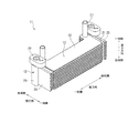
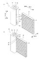
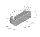
図1は、熱交換器の外観を示す図である。
アルミ製の熱交換器11は、二酸化炭素等の冷媒(第一の熱媒体)と、ブライン(第二の熱媒体)との間で熱交換を行なうプレート式であり、冷媒を案内する冷媒案内部12と、ブラインを案内するブライン案内部13と、を備える。
"Constitution"
In the following description, the three directions orthogonal to each other are, for convenience, the vertical direction, the horizontal direction, and the height direction.
FIG. 1 is a diagram showing the appearance of the heat exchanger.
The aluminum heat exchanger 11 is a plate type that exchanges heat between a refrigerant such as carbon dioxide (first heat medium) and brine (second heat medium), and is a refrigerant guide that guides the refrigerant. A
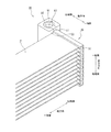
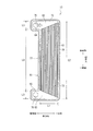
図2は、冷媒案内部の外観を示す図である。
ここでは、ブライン案内部13を省略した状態の冷媒案内部12を示す。
冷媒案内部12は、複数の冷媒チューブ21(第一のプレート体)と、入口フランジ22と、一次分流ヘッダ23と、二次分流ヘッダ24と、一次合流ヘッダ25と、二次合流ヘッダ26と、出口フランジ27と、を備える。冷媒チューブ21の数は、ここでは10枚である。
FIG. 2 is a diagram showing the appearance of the refrigerant guide unit.
Here, the
The
入口フランジ22は、一次分流ヘッダ23における高さ方向の一端側に接続され、冷媒を導入する。一次分流ヘッダ23は、二次分流ヘッダ24における横方向の他端側に接続され、冷媒を一段階目として一次分流させる。二次分流ヘッダ24は、冷媒チューブ21における縦方向の一端側に接続され、冷媒を二段階目として二次分流させる。一次合流ヘッダ25は、冷媒チューブ21における縦方向の他端側に接続され、冷媒を一段階目として一次合流させる。二次合流ヘッダ26は、一次合流ヘッダ25における横方向の他端側に接続され、冷媒を二段階目として二次合流させる。出口フランジ27は、二次合流ヘッダ26における高さ方向の一端側に接続され、冷媒を排出する。
The
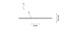
図3は、冷媒チューブの断面図である。
冷媒チューブ21は、縦方向及び横方向を面方向とし、高さ方向を厚み方向とする板状の外形であり、面方向に沿って形成された多数の連通孔31に冷媒が案内される。連通孔31は、断面が円形であり、冷媒チューブ21を縦方向に貫通し、横方向に間隔を空けて並べて形成されている。連通孔31の数は、ここでは34個である。
FIG. 3 is a cross-sectional view of the refrigerant tube.
The
図4は、一次合流ヘッダの構成図である。
ここでは、一次合流ヘッダ25を例に説明するが、二次分流ヘッダ24についても同様である。
図中の(a)は一次合流ヘッダ25の組み立て前の状態を示し、図中の(b)は一次合流ヘッダ25の組み立て後の状態を示す。
一次合流ヘッダ25は、横方向及び高さ方向を面方向とし、縦方向を厚み方向とする板状の外形であり、流路35(第一の流路)と、差込口36(第一の差込口)と、キャップ37(第一のキャップ)と、を備える。これら流路35、差込口36、及びキャップ37の数は、夫々、冷媒チューブ21の数と同じである。
流路35は、断面が円形であり、一次合流ヘッダ25を横方向に貫通し、高さ方向に間隔を空けて並べて形成されている。
FIG. 4 is a block diagram of the primary confluence header.
Here, the
(A) in the figure shows a state before assembling the
The
The
差込口36は、一次合流ヘッダ25における縦方向の内側を向いた端面38から各流路35の中心へと横方向の全体にわたって連通し、冷媒チューブ21における縦方向の端部を差し込み可能な隙間である。すなわち、差込口36における高さ方向の隙間寸法は、冷媒チューブ21における高さ方向の寸法と等しい。端面38は、横方向及び高さ方向を面方向としている。
キャップ37は、流路35及び差込口36の双方における横方向の一端側を封止する部品である。各キャップ37は、一次合流ヘッダ25における横方向の一端側から嵌め込まれ、ろう付けされる。
The
The
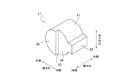
図5は、キャップの外観図である。
キャップ37は、流路35に嵌り込む円柱部41と、差込口36に嵌り込む角柱部42と、を備える。すなわち、円柱部41の直径は、流路35の直径と等しく、角柱部42における高さ方向の寸法は、差込口36における高さ方向の隙間寸法と等しい。キャップ37における横方向の内側には、縦方向の外側に位置する端面43と、縦方向の内側に位置する端面44(規制部)と、が形成されている。端面43は、縦方向及び高さ方向を面方向とし、円柱部41における縦方向の外側半分に相当する。端面44は、縦方向及び高さ方向を面方向とし、円柱部41における縦方向の内側半分と角柱部42とに相当する。端面44は、段差面45(規制部)を介して端面43よりも横方向の外側に配置されている。
FIG. 5 is an external view of the cap.
The
図6は、冷媒チューブとキャップとの位置関係を示す図である。
ここでは、差込口36に対して冷媒チューブ21における縦方向の端部を差し込んだ状態を示している。このとき、冷媒チューブ21における縦方向の端面のうち、横方向の外側が、キャップ37の段差面45に当接することで、冷媒チューブ21における縦方向の位置が規制される。また、冷媒チューブ21における横方向の一端面のうち、縦方向の外側が、キャップ37の端面44に当接することで、冷媒チューブ21における横方向の位置が規制される。
FIG. 6 is a diagram showing the positional relationship between the refrigerant tube and the cap.
Here, a state in which the end portion of the
図7は、二次合流ヘッダの構成図である。
ここでは、二次合流ヘッダ26を例に説明するが、一次分流ヘッダ23についても同様である。
図中の(a)は二次合流ヘッダ26の組み立て前の状態を示し、図中の(b)は二次合流ヘッダ26の組み立て後の状態を示す。
二次合流ヘッダ26は、高さ方向に延びる角柱状の外形であり、流路51(第二の流路)と、差込口52(第二の差込口)と、接続キャップ53と、キャップ54(第二のキャップ)と、を備える。
FIG. 7 is a block diagram of the secondary merging header.
Here, the
(A) in the figure shows a state before assembling the
The
流路51は、断面が円形であり、二次合流ヘッダ26を高さ方向に貫通している。
差込口52は、二次合流ヘッダ26における横方向の内側を向いた端面55から流路51の中心へと高さ方向の全体にわたって連通し、一次合流ヘッダ25における横方向の他端部を差し込み可能な隙間である。すなわち、差込口52における縦方向の隙間寸法は、一次合流ヘッダ25における縦方向の寸法と等しい。端面55は、縦方向及び高さ方向を面方向としている。
The
The
接続キャップ53は、流路51及び差込口52の双方における高さ方向の一端側に嵌め込まれ、出口フランジ27に接続される部品である。接続キャップ53は、流路51に嵌り込む環状板部56と、差込口52に嵌り込む角板部57と、を備える。すなわち、環状板部56における外側の直径は、流路51の直径と等しく、角板部57における縦方向の寸法は、差込口52における縦方向の隙間寸法と等しい。接続キャップ53は、二次合流ヘッダ26における高さ方向の一端側から嵌め込まれ、ろう付けされる。
The
キャップ54は、流路51及び差込口52の双方における高さ方向の他端側を封止する部品である。キャップ54は、流路51に嵌り込む円板部58と、差込口52に嵌り込む角板部59と、を備える。すなわち、円板部58の直径は、流路51の直径と等しく、角板部59における縦方向の寸法は、差込口52における縦方向の隙間寸法と等しい。キャップ54は、二次合流ヘッダ26における高さ方向の他端側から嵌め込まれ、ろう付けされる。
The
図8は、二次合流ヘッダに対する一次合流ヘッダの組み付けを示す図である。
図中の(a)は組み付け前の状態を示し、図中の(b)は組み付け後の状態を示す。
二次合流ヘッダ26の差込口52に対して、一次合流ヘッダ25における横方向の他端部が差し込まれ、ろう付けされる。
FIG. 8 is a diagram showing the assembly of the primary merging header with respect to the secondary merging header.
(A) in the figure shows the state before assembling, and (b) in the figure shows the state after assembling.
The other end of the
図9は、冷媒チューブの組み付けを示す図である。
一次合流ヘッダ25の各差込口36に対して、夫々、冷媒チューブ21における縦方向の他端部が差し込まれ、ろう付けされる。このとき、二次合流ヘッダ26における横方向の内側を向いた端面55は、冷媒チューブ21における横方向の他端面のうち、縦方向の外側と当接することで、冷媒チューブ21における横方向の位置及び角度が規制される。
キャップ37の端面44から二次合流ヘッダ26の端面55までの距離は、冷媒チューブ21における横方向の長さに等しい。また、分流側に配置されたキャップ37の段差面45から、合流側に配置されたキャップ37の段差面45までの距離は、冷媒チューブ21における縦方向の長さに等しい。
FIG. 9 is a diagram showing the assembly of the refrigerant tube.
The other end of the
The distance from the
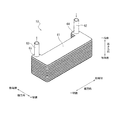
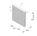
図10は、ブライン案内部の外観を示す図である。
ここでは、冷媒案内部12を省略した状態のブライン案内部13を示す。
ブライン案内部13は、複数のブラインチューブ61(第二のプレート体)と、入口パイプ62と、出口パイプ63と、を備える。冷媒チューブ21とブラインチューブ61とは交互に積層され、且つ冷媒チューブ21がブラインチューブ61によって挟まれるようにするため、ブラインチューブ61の数は、ここでは11枚となる。
FIG. 10 is a diagram showing the appearance of the brine guide portion.
Here, the
The
ブラインチューブ61は、縦方向及び横方向を面方向とし、高さ方向を厚み方向とする板状の外形であり、面方向に沿って内部に形成された流路にブラインが案内される。ブラインチューブ61における縦方向の他端側には、横方向の他端側に突出した突出部64が形成され、ブラインチューブ61における縦方向の一端側には、横方向の他端側に突出した突出部65が形成されている。突出部64には、高さ方向に延びる入口パイプ62が接続され、入口パイプ62はブラインを導入する。突出部65には、高さ方向に延びる出口パイプ63が接続され、出口パイプ63はブラインを排出する。
The
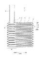
図11は、ブライン案内部の断面図である。
ここでは、出口パイプ63の側を例に説明するが、入口パイプ62の側についても同様である。
各ブラインチューブ61は、アッパプレート71とロアプレート72とを接合した中空構造とされ、内部には波形のインナーフィン73が収容されている。
各ブラインチューブ61において、アッパプレート71の突出部65には、アッパ接続口74が形成され、ロアプレート72の突出部65には、ロア接続口75が形成されている。但し、最下層のブラインチューブ61については、ロア接続口75は形成されていない。アッパ接続口74、ロア接続口75は、全て同軸上に配置されている。最上層のアッパ接続口74には、出口パイプ63が接続され、ろう付けされる。各ロア接続口75は、夫々、一つ下層のアッパ接続口74に接続され、ろう付けされる。
FIG. 11 is a cross-sectional view of the brine guide portion.
Here, the side of the
Each
In each
インナーフィン73は、縦方向及び横方向を面方向とし、高さ方向を厚み方向とする波板からなり、インナーフィン73における高さ方向の外側寸法は、ブラインチューブ61における高さ方向の内側寸法に等しい。すなわち、インナーフィン73における各山の頂点がアッパプレート71の天井面に接すると共に、インナーフィン73における各谷の頂点がロアプレート72の床面に接することで、縦方向に連通し、横方向に並んだ複数の流路81が形成される。
The
図12は、ブラインチューブの内部を示す斜視図である。
ここでは、アッパプレート71を省略した最上層のブラインチューブ61を示す。
インナーフィン73は、高さ方向から見て、横方向における一端側の底辺76と、他端側の底辺77とが平行な台形であり、底辺76の両端にある二つの内角が互いに等しく、且つ底辺77の両端にある二つの内角も互いに等しい。インナーフィン73は、ロアプレート72の床面に置かれ、ろう付けされる。
FIG. 12 is a perspective view showing the inside of the brine tube.
Here, the uppermost
The
図13は、ブラインチューブの内部を示す平面図である。
インナーフィン73における横方向の長さは、ロアプレート72における横方向の内側寸法L1と同等であるため、横方向の位置が規制される。インナーフィン73における底辺76の長さは、ロアプレート72における縦方向の内側寸法L2と同等であるため、縦方向の位置が規制される。またインナーフィン73における底辺77の長さは、ロアプレート72における縦方向の内側寸法L2から、突出部64及び突出部65における縦方向の内側寸法(L3×2)を引いた寸法L4(=L2−(L3×2))と同等である。
FIG. 13 is a plan view showing the inside of the brine tube.
Since the lateral length of the
各ブラインチューブ61の内部のうち、入口側の突出部64からインナーフィン73に至るまでの領域を導入流路82とし、インナーフィン73から出口側の突出部65に至るまでの領域を排出流路83とする。高さ方向から見て、インナーフィン73が台形にされていることで、導入流路82は、横方向の一端側に向かうほど縦方向の寸法が狭くなり、排出流路83は、横方向の他端側に向かうほど縦方向の寸法が広くなる。
Of the inside of each
次に、冷媒、及びブラインの流れについて説明する。
入口フランジ22から導入された冷媒は、一次分流ヘッダ23の流路51を通り、最初の分流として二次分流ヘッダ24の各流路35へと振り分けられる。このとき、冷媒は、高さ方向の一端側から他端側へ向かう流れから、横方向の他端側から一端側へ向かう流れへと直角に方向転換される。一次分流された冷媒は、二次分流ヘッダ24の流路35を通り、次なる分流として冷媒チューブ21の各連通孔31へと振り分けられる。このとき、冷媒は、横方向の他端側から一端側へ向かう流れから、縦方向の一端側から他端側へ向かう流れへと直角に方向転換される。
Next, the flow of the refrigerant and the brine will be described.
The refrigerant introduced from the
二次分流された冷媒は、冷媒チューブ21の連通孔31を通り、最初の合流として一次合流ヘッダ25でまとめられる。このとき、冷媒は、縦方向の一端側から他端側へ向かう流れから、横方向の一端側から他端側へ向かう流れへと直角に方向転換される。一次合流された冷媒は、一次合流ヘッダ25の流路35を通り、次なる合流として二次合流ヘッダ26の流路51でまとめられ、出口フランジ27から排出される。このとき、冷媒は、横方向の一端側から他端側へ向かう流れから、高さ方向の他端側から一端側へ向かう流れへと方向転換される。
The secondary diverted refrigerant passes through the
入口パイプ62から導入されたブラインは、アッパプレート71のアッパ接続口74やロアプレート72のロア接続口75を通り、最初の分流として各ブラインチューブ61の導入流路82へと振り分けられる。このとき、ブラインは、高さ方向の一端側から他端側へ向かう流れから、横方向の他端側から一端側へ向かう流れへと直角に方向転換される。分流されたブラインは、導入流路82を通り、次なる分流としてインナーフィン73の各流路81へと振り分けられる。このとき、ブラインは、横方向の他端側から一端側へ向かう流れから、縦方向の他端側から一端側へ向かう流れへと直角に方向転換される。
The brine introduced from the
分流されたブラインは、インナーフィン73の流路81を通り、最初の合流として排出流路83でまとめられる。このとき、ブラインは、縦方向の他端側から一端側へ向かう流れから、横方向の一端側から他端側へ向かう流れへと直角に方向転換される。合流されたブラインは、排出流路83を通り、次なる合流としてアッパプレート71のアッパ接続口74やロアプレート72のロア接続口75でまとめられ、出口パイプ63から排出される。このとき、ブラインは、横方向の一端側から他端側へ向かう流れから、高さ方向の他端側から一端側へ向かう流れへと方向転換される。
上記のように、冷媒チューブ21に冷媒が案内され、且つブラインチューブ61にブラインが案内されるときに、冷媒とブラインとの間で熱交換が行なわれる。冷媒チューブ21における冷媒の案内方向と、ブラインチューブ61におけるブラインの案内方向と、は反対である。
The separated brine passes through the
As described above, when the refrigerant is guided to the
《作用》
次に、実施形態の主要な作用効果について説明する。
冷媒チューブ21に冷媒を分流させるヘッダ、及び合流させるヘッダを、夫々、一つの配管によって形成すると、各ヘッダが大型化してしまい、特に二酸化炭素等の冷媒は高圧で使用されるため、耐圧仕様にするほど大型化してしまう。
そこで、冷媒チューブ21の連通孔31を通過する前に冷媒を複数段階に分けて分流させ、且つ連通孔31を通過した後に冷媒を複数段階に分けて合流させる。まず一次分流ヘッダ23が、冷媒を冷媒チューブ21の夫々に分流させ、次に二次分流ヘッダ24が、冷媒を連通孔31の夫々に分流させる。次に一次合流ヘッダ25が、冷媒の夫々を冷媒チューブ21ごとに合流させ、次に二次合流ヘッダ26が、冷媒の夫々を一つに合流させる。
《Action》
Next, the main action and effect of the embodiment will be described.
If a header for splitting the refrigerant and a header for merging the refrigerant are formed in the
Therefore, the refrigerant is divided into a plurality of stages before passing through the
このように、複数段階に分けて分流と合流を行なうため、一つの配管によって分流又は合流を行なう場合よりも、大型化を抑制することができる。また、一次分流ヘッダ23及び二次分流ヘッダ24を別体で構成し、一次合流ヘッダ25及び二次合流ヘッダ26を別体で構成しているので、耐圧仕様であっても小型化を図りやすい。
また、一次分流ヘッダ23及び二次分流ヘッダ24で、冷媒を分流させる際には、冷媒の流れを略直角に方向転換させ、一次合流ヘッダ25及び二次合流ヘッダ26で、冷媒を合流させる際には、冷媒の流れを略直角に方向転換させている。このように、略直角に方向転換させながら冷媒の分流又は合流を行なうので、省スペース化を図ることができる。
In this way, since the splitting and merging are performed in a plurality of stages, it is possible to suppress the increase in size as compared with the case where the splitting or merging is performed by one pipe. Further, since the
Further, when the refrigerant is diverted in the
また、一次合流ヘッダ25(又は二次分流ヘッダ24)には、横方向に貫通した流路35と、端面38から流路35へと連通した差込口36とを形成し、流路35及び差込口36の双方にキャップ37を嵌め込んでいる。そして、差込口36に冷媒チューブ21を差し込むことで、一次合流(又は二次分流)のための構造が実現される。このように、コンパクトな構造によって、冷媒を合流(又は分流)することができる。
キャップ37には、冷媒チューブ21と当接する端面44及び段差面45が形成されている。これにより、冷媒チューブ21における縦方向の位置、及び横方向の位置が規制されるので、容易に位置決めを行なうことができるので、組み付け時の作業性に優れる。
Further, in the primary confluence header 25 (or the secondary diversion header 24), a
The
また、二次合流ヘッダ26(又は一次分流ヘッダ23)には、高さ方向に貫通した流路51と、端面55から流路51へと連通した差込口52とを形成し、流路51及び差込口52の双方に、接続キャップ53及びキャップ54を嵌め込んでいる。そして、差込口52に一次合流ヘッダ25を差し込むことで、二次合流(又は一次分流)のための構造が実現される。このように、コンパクトな構造によって冷媒を合流(又は分流)することができる。
また、二次合流ヘッダ26(又は一次分流ヘッダ23)の端面55は、冷媒チューブ21と当接する。これにより、冷媒チューブ21における横方向の位置、及び角度が規制され、容易に位置決めを行なうことができるので、組み付け時の作業性に優れる。
Further, the secondary merging header 26 (or the primary diversion header 23) is formed with a
Further, the
また、冷媒チューブ21とブラインチューブ61とを個別に積層しているので、冷媒とブラインとを隔てる隔壁が二重になる。一枚の隔壁を共有しているような構造では、内部漏れが生じると、高圧の冷媒がブラインの流路に侵入することもあったが、こうした問題を抑制できる。仮に、冷媒チューブ21から冷媒が漏れたとしても、ブラインチューブ61へ侵入することなく、目視で確認できるため速やかに発見することができる。
また、冷媒チューブ21の連通孔31、一次合流ヘッダ25(又は二次分流ヘッダ24)の流路35、二次合流ヘッダ26(又は一次分流ヘッダ23)の流路51は、断面が円形にされているので、内圧に対する耐久性を高めることができる。
また、一次分流ヘッダ23及び二次合流ヘッダ26の互いを、横方向における同一側に配置している。これにより、互いを横方向において異なる側に配置する場合と比較して、熱交換器11における横方向の寸法が増大することを抑制できるので、搭載性が向上する。
Further, since the
Further, the
Further, the primary branching
また、ブラインチューブ61に内蔵されたインナーフィン73は、高さ方向から見て、横方向における一端側の底辺76と、他端側の底辺77とが平行な台形である。インナーフィン73における横方向の長さは、ロアプレート72における横方向の内側寸法L1と同等であり、且つ底辺76の長さは、ロアプレート72における縦方向の内側寸法L2と同等である。これにより、ロアプレート72にインナーフィン73を載せるときに、横方向の位置、及び縦方向の位置が規制され、容易に位置決めを行なうことができるので、組み付け時の作業性に優れる。
Further, the
また、高さ方向から見て、インナーフィン73が台形にされていることで、導入流路82は、横方向の一端側に向かうほど縦方向の寸法が狭くされている。導入流路82のブラインは、横方向の流速をもっているため、導入流路82における縦方向の寸法が一定であると、横方向の一端側へと向かいやすくなる。そのため、インナーフィン73によって形成された多数の流路81のうち、横方向の一端側へ多く流れやすくなり、不均一な流れになってしまう。そこで、導入流路82において、横方向の一端側に向かうほど縦方向の寸法が狭くすることで、横方向の一端側へ多く流れることを抑制する。これにより、各流路81に流れるブラインの均等化を図ることができる。
Further, since the
また、突出部64及び突出部65を、横方向において一次分流ヘッダ23及び二次合流ヘッダ26と同一の側に配置している。これにより、横方向において一次分流ヘッダ23及び二次合流ヘッダ26と反対側に配置する場合と比較して、熱交換器11における横方向の寸法が増大することを抑制できるので、搭載性が向上する。さらに、突出部64及び突出部65の互いを、横方向における同一側に配置している。これにより、互いを横方向において異なる側に配置する場合と比較して、熱交換器11における横方向の寸法が増大することを抑制できるので、搭載性が向上する。
Further, the projecting
《変形例》
実施形態では、二次分流ヘッダ24及び一次合流ヘッダ25が、夫々、一つの板状の部材によって形成されているが、これに限定されるものではない。
図14は、一次合流ヘッダの変形例を示す図である。
ここでは、一次合流ヘッダ25を、各層ごとに、つまり冷媒チューブ21ごとに個別に形成し、これらを高さ方向に積層し、ろう付けによって一体化している。これにより、冷媒チューブ21やブラインチューブ61の積層数に増減要求があっても、容易に対応することができるので、設計の自由度が向上する。
<< Modification example >>
In the embodiment, the
FIG. 14 is a diagram showing a modified example of the primary confluence header.
Here, the
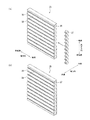
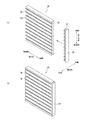
実施形態では、二次分流ヘッダ24及び一次合流ヘッダ25において、各層に一つずつキャップ37を嵌め込んでいるが、これに限定されるものではない。
図15は、一次合流ヘッダの変形例を示す図である。
図中の(a)は一次合流ヘッダ25の組み立て前の状態を示し、図中の(b)は一次合流ヘッダ25の組み立て後の状態を示す。
ここでは、高さ方向に沿って並んだ複数のキャップ37を一体化する連結プレート39(連結部材)を備えており、各キャップ37を予め一つの連結プレート39に固定しておくことで、全てのキャップ37を同時に嵌め込めるようにしている。これにより、組み付けの作業性が向上する。
実施形態では、冷媒チューブ21及びブラインチューブ61を寝かせた状態で高さ方向に配列しているが、これに限定されるものではない。例えば、冷媒チューブ21及びブラインチューブ61を立たせた状態で縦方向や横方向に配列してもよい。
実施形態では、二酸化炭素等の冷媒を第一の熱媒体として使用し、ブラインを第二の熱媒体として使用しているが、これに限定されるものではなく、他の如何なる熱媒体にも適応できる。
In the embodiment, in the
FIG. 15 is a diagram showing a modified example of the primary confluence header.
(A) in the figure shows a state before assembling the
Here, a connecting plate 39 (connecting member) for integrating a plurality of
In the embodiment, the
In the embodiment, a refrigerant such as carbon dioxide is used as the first heat medium and brine is used as the second heat medium, but the present invention is not limited to this, and is applicable to any other heat medium. it can.
以上、限られた数の実施形態を参照しながら説明したが、権利範囲はそれらに限定されるものではなく、上記の開示に基づく実施形態の改変は、当業者にとって自明のことである。 Although the above description has been made with reference to a limited number of embodiments, the scope of rights is not limited thereto, and modifications of the embodiments based on the above disclosure are obvious to those skilled in the art.
11 熱交換器
21 冷媒チューブ(第一のプレート体)
23 一次分流ヘッダ
24 二次分流ヘッダ
25 一次合流ヘッダ
26 二次合流ヘッダ
31 連通孔
35 流路(第一の流路)
36 差込口(第一の差込口)
37 キャップ(第一のキャップ)
39 連結プレート(連結部材)
44 端面(規制部)
45 段差面(規制部)
51 流路(第二の流路)
52 差込口(第二の差込口)
53 接続キャップ
54 キャップ(第二のキャップ)
61 ブラインチューブ(第二のプレート体)
11
23
36 outlet (first outlet)
37 cap (first cap)
39 Connecting plate (connecting member)
44 End face (Regulatory part)
45 Step surface (regulatory part)
51 flow path (second flow path)
52 outlet (second outlet)
53
61 Brine tube (second plate body)
Claims (7)
板状の外形であり、面方向に沿って内部に形成された流路に第二の熱媒体が案内される複数の第二のプレート体と、を備え、
前記第一のプレート体と前記第二のプレート体とが交互に積層され、前記第一の熱媒体と前記第二の熱媒体との間で熱交換を行なう熱交換器であって、
前記連通孔を通過する前に前記第一の熱媒体を複数段階に分けて分流させ、且つ前記連通孔を通過した後に前記第一の熱媒体を複数段階に分けて合流させ、
入口から案内された前記第一の熱媒体を分流させる一次分流ヘッダと、
前記一次分流ヘッダから案内された前記第一の熱媒体を、前記連通孔の夫々に分流させる二次分流ヘッダと、
前記連通孔から案内された前記第一の熱媒体の夫々を、前記第一のプレート体ごとに合流させる一次合流ヘッダと、
前記一次合流ヘッダから案内された前記第一の熱媒体の夫々を、一つに合流させて出口に案内する二次合流ヘッダと、を備え、
前記面方向のうち、互いに直交する方向を、縦方向及び横方向とし、前記面方向に直角な方向を、高さ方向とし、
前記一次分流ヘッダは、前記高さ方向に延び、前記二次分流ヘッダにおける前記横方向の他端側に配置され、
前記二次合流ヘッダは、前記高さ方向に延び、前記一次合流ヘッダにおける前記横方向の他端側に配置され、
前記一次分流ヘッダ、及び前記二次合流ヘッダの夫々は、
前記高さ方向に沿って貫通した第二の流路と、
前記横方向の内側を向いた端面から前記第二の流路へと前記高さ方向の全体にわたって連通し、前記二次分流ヘッダ又は前記一次合流ヘッダにおける前記横方向の他端部を差し込み可能な第二の差込口と、
前記第二の流路及び前記第二の差込口の双方における前記高さ方向の一端側を封止し、前記入口又は前記出口に接続される接続キャップと、
前記第二の流路及び前記第二の差込口の双方における前記高さ方向の他端側を封止する第二のキャップと、を備えることを特徴とする熱交換器。 A plurality of first plate bodies having a plate-like outer shape and in which the first heat medium is guided to a plurality of communication holes formed along the plane direction.
It has a plate-like outer shape, and includes a plurality of second plate bodies in which a second heat medium is guided to a flow path formed inside along the plane direction.
A heat exchanger in which the first plate body and the second plate body are alternately laminated to exchange heat between the first heat medium and the second heat medium.
Before passing through the communication hole, the first heat medium is divided into a plurality of stages and split, and after passing through the communication hole, the first heat medium is divided into a plurality of stages and merged .
A primary diversion header that diverts the first heat medium guided from the inlet, and
A secondary diversion header that diverts the first heat medium guided from the primary diversion header into each of the communication holes, and a secondary diversion header.
A primary merging header for merging each of the first heat media guided from the communication hole for each of the first plate bodies,
A secondary merging header that merges each of the first heat media guided from the primary merging header into one and guides the first heat medium to the outlet is provided.
Of the surface directions, the directions orthogonal to each other are defined as the vertical direction and the horizontal direction, and the direction perpendicular to the surface direction is defined as the height direction.
The primary diversion header extends in the height direction and is arranged on the other end side of the secondary diversion header in the lateral direction.
The secondary merging header extends in the height direction and is arranged on the other end side of the primary merging header in the lateral direction.
The primary divergence header and the secondary merging header, respectively,
A second flow path penetrating along the height direction,
It communicates from the inwardly facing end face in the lateral direction to the second flow path over the entire height direction, and the other end portion in the lateral direction of the secondary diversion header or the primary confluence header can be inserted. The second outlet and
A connection cap that seals one end side in the height direction in both the second flow path and the second insertion port and is connected to the inlet or the outlet.
A heat exchanger comprising: a second cap for sealing the other end side in the height direction in both the second flow path and the second insertion port.
前記一次合流ヘッダ、及び前記二次合流ヘッダは、前記第一の熱媒体を合流させる際に、前記第一の熱媒体の流れを略直角に方向転換させることを特徴とする請求項1に記載の熱交換器。 The primary diversion header and the secondary diversion header divert the flow of the first heat medium at a substantially right angle when the first heat medium is split.
The primary confluent header, and the secondary merge header, when for combining the first heat medium, according to claim 1, characterized in that at a substantially right angle to divert the flow of the first heat medium Heat exchanger.
前記連通孔は、前記第一のプレート体を前記縦方向に貫通し、前記横方向に間隔を空けて並べて形成され、
前記二次分流ヘッダ、及び前記一次合流ヘッダは、夫々、前記横方向に延び、前記第一のプレート体における前記縦方向の両端側に配置され、
前記二次分流ヘッダ、及び前記一次合流ヘッダの夫々は、
前記横方向に沿って貫通した第一の流路と、
前記縦方向の内側を向いた端面から前記第一の流路へと前記横方向の全体にわたって連通し、前記第一のプレート体における前記縦方向の端部を差し込み可能な第一の差込口と、
前記第一の流路及び前記第一の差込口の双方における前記横方向の一端側を封止する第一のキャップと、を備えることを特徴とする請求項1又は2に記載の熱交換器。 Of the surface directions, the directions orthogonal to each other are defined as the vertical direction and the horizontal direction.
The communication holes are formed by penetrating the first plate body in the vertical direction and arranging them side by side at intervals in the horizontal direction.
The secondary diversion header and the primary confluence header, respectively, extend in the lateral direction and are arranged on both ends in the vertical direction of the first plate body.
Each of the secondary diversion header and the primary confluence header
The first flow path penetrating along the lateral direction and
A first insertion port that communicates from the inwardly facing end surface in the vertical direction to the first flow path over the entire horizontal direction and into which the vertical end portion of the first plate body can be inserted. When,
The heat exchange according to claim 1 or 2 , further comprising a first cap for sealing one end side in the lateral direction in both the first flow path and the first insertion port. vessel.
前記横方向の内側を向いた端面が、前記第一のプレート体における前記横方向の他端面のうち、前記縦方向の端側と当接することで、前記二次分流ヘッダ又は前記一次合流ヘッダにおける前記横方向の位置及び角度を規制することを特徴とする請求項1〜4の何れか一項に記載の熱交換器。 The primary divergence header and the secondary merging header, respectively,
The end face facing inward in the horizontal direction abuts on the end side in the vertical direction of the other end face in the horizontal direction of the first plate body, thereby causing the secondary divergence header or the primary merging header. The heat exchanger according to any one of claims 1 to 4, wherein the position and angle in the lateral direction are regulated.
前記二次分流ヘッダ、及び前記一次合流ヘッダの夫々は、
前記高さ方向に沿って並んだ複数の前記第一のキャップを一体化する連結部材を備えることを特徴とする請求項3又は4に記載の熱交換器。 The direction perpendicular to the surface direction is defined as the height direction.
Each of the secondary diversion header and the primary confluence header
The heat exchanger according to claim 3 or 4 , further comprising a connecting member that integrates a plurality of the first caps arranged along the height direction.
Priority Applications (2)
| Application Number | Priority Date | Filing Date | Title |
|---|---|---|---|
| JP2017110324A JP6889618B2 (en) | 2017-06-02 | 2017-06-02 | Heat exchanger |
| PCT/JP2018/019007 WO2018221230A1 (en) | 2017-06-02 | 2018-05-17 | Heat exchanger |
Applications Claiming Priority (1)
| Application Number | Priority Date | Filing Date | Title |
|---|---|---|---|
| JP2017110324A JP6889618B2 (en) | 2017-06-02 | 2017-06-02 | Heat exchanger |
Publications (2)
| Publication Number | Publication Date |
|---|---|
| JP2018204861A JP2018204861A (en) | 2018-12-27 |
| JP6889618B2 true JP6889618B2 (en) | 2021-06-18 |
Family
ID=64455132
Family Applications (1)
| Application Number | Title | Priority Date | Filing Date |
|---|---|---|---|
| JP2017110324A Active JP6889618B2 (en) | 2017-06-02 | 2017-06-02 | Heat exchanger |
Country Status (2)
| Country | Link |
|---|---|
| JP (1) | JP6889618B2 (en) |
| WO (1) | WO2018221230A1 (en) |
Families Citing this family (4)
| Publication number | Priority date | Publication date | Assignee | Title |
|---|---|---|---|---|
| WO2021172331A1 (en) * | 2020-02-27 | 2021-09-02 | 三菱重工業株式会社 | Heat exchange core, heat exchanger, and method for manufacturing heat exchange core |
| JP7505894B2 (en) * | 2020-02-27 | 2024-06-25 | 三菱重工業株式会社 | Heat exchange core, heat exchanger, maintenance method for heat exchanger, and manufacturing method for heat exchange core |
| JP7437971B2 (en) * | 2020-02-27 | 2024-02-26 | 三菱重工業株式会社 | Method of manufacturing heat exchange core |
| CN114665188B (en) * | 2022-03-30 | 2023-11-21 | 宁德时代新能源科技股份有限公司 | Water cooling plate assembly, water cooling system, battery, box body of battery and power utilization device |
Family Cites Families (3)
| Publication number | Priority date | Publication date | Assignee | Title |
|---|---|---|---|---|
| JP2004101144A (en) * | 2002-09-12 | 2004-04-02 | Denso Corp | Internal heat exchanger for vapor compression type refrigerator |
| JP5287949B2 (en) * | 2011-07-28 | 2013-09-11 | ダイキン工業株式会社 | Heat exchanger |
| US9551540B2 (en) * | 2011-11-22 | 2017-01-24 | Daikin Industries, Ltd. | Heat exchanger |
-
2017
- 2017-06-02 JP JP2017110324A patent/JP6889618B2/en active Active
-
2018
- 2018-05-17 WO PCT/JP2018/019007 patent/WO2018221230A1/en not_active Ceased
Also Published As
| Publication number | Publication date |
|---|---|
| JP2018204861A (en) | 2018-12-27 |
| WO2018221230A1 (en) | 2018-12-06 |
Similar Documents
| Publication | Publication Date | Title |
|---|---|---|
| JP6889618B2 (en) | Heat exchanger | |
| KR101815405B1 (en) | Heat exchanger and production method for heat exchanger | |
| KR101918869B1 (en) | Heat transfer plate and plate heat exchanger | |
| KR102243230B1 (en) | Heat transfer plate and plate heat exchanger | |
| WO2015113496A1 (en) | Board-type heat exchanger | |
| FI124763B (en) | Plate heat exchanger and method for constructing multiple passages in a plate heat exchanger | |
| US9927184B2 (en) | Heat exchanger | |
| KR102217703B1 (en) | Heat exchange plate for plate-type heat exchanger and plate-type heat exchanger provided with said heat exchange plate | |
| JP7045195B2 (en) | Heat exchanger | |
| JP6578964B2 (en) | Laminate heat exchanger | |
| US20190033016A1 (en) | Heat Exchanger | |
| JP2006010130A (en) | Multi-fluid heat exchanger | |
| JP2006183969A (en) | Heat-exchange core of stacked oil cooler | |
| KR102755747B1 (en) | Plate heat exchanger device | |
| CN111765786A (en) | Heat Exchangers and Heat Exchanger Assemblies | |
| JP6938960B2 (en) | Micro flow path heat exchanger | |
| CN104677149A (en) | Oil Cooler | |
| KR20170029768A (en) | Heat exchanger of double-sided flow path type | |
| JP2005233454A (en) | Heat exchanger | |
| JP2023068941A (en) | Heat exchanger and heat exchanger manufacturing method | |
| US20140196869A1 (en) | Plate heat exchanger with tension ties | |
| KR102582442B1 (en) | Printed circuit type heat exchanger | |
| JP6281422B2 (en) | Laminate heat exchanger | |
| WO2025022993A1 (en) | Heat exchanger | |
| JP6894200B2 (en) | Heat sink for electrical equipment |
Legal Events
| Date | Code | Title | Description |
|---|---|---|---|
| RD04 | Notification of resignation of power of attorney |
Free format text: JAPANESE INTERMEDIATE CODE: A7424 Effective date: 20190411 |
|
| A621 | Written request for application examination |
Free format text: JAPANESE INTERMEDIATE CODE: A621 Effective date: 20200528 |
|
| A131 | Notification of reasons for refusal |
Free format text: JAPANESE INTERMEDIATE CODE: A131 Effective date: 20210309 |
|
| A521 | Request for written amendment filed |
Free format text: JAPANESE INTERMEDIATE CODE: A523 Effective date: 20210419 |
|
| TRDD | Decision of grant or rejection written | ||
| A01 | Written decision to grant a patent or to grant a registration (utility model) |
Free format text: JAPANESE INTERMEDIATE CODE: A01 Effective date: 20210511 |
|
| A61 | First payment of annual fees (during grant procedure) |
Free format text: JAPANESE INTERMEDIATE CODE: A61 Effective date: 20210521 |
|
| R150 | Certificate of patent or registration of utility model |
Ref document number: 6889618 Country of ref document: JP Free format text: JAPANESE INTERMEDIATE CODE: R150 |
|
| S533 | Written request for registration of change of name |
Free format text: JAPANESE INTERMEDIATE CODE: R313533 |
|
| R350 | Written notification of registration of transfer |
Free format text: JAPANESE INTERMEDIATE CODE: R350 |