以下、本発明の好ましい実施形態について図面を参照して説明する。まず、図1〜図15を用いて、本発明に係る遊技機の一例であるスロットマシン1の構成について説明する。ここで、図1はスロットマシン1の正面図であり、図2はスロットマシン1の機能の概略を示すブロック図であり、図3はこのスロットマシン1における制御システムを示すブロック図であり、図4はリールの外周面の図柄配列の一例を示す説明図であり、図5は役と図柄の組み合わせを示す説明図であり、図6は特定図柄を示す説明図であり、図7は各遊技状態に対して設定された役抽選テーブルのうち再遊技役の当選確率を示す説明図であり、図8は各遊技状態に対して設定された役抽選テーブルのうち入賞役の当選確率を示す説明図であり、図9は各遊技状態に対して設定された役抽選テーブルのうち特別役の当選確率を示す説明図であり、図10は役に割り当てられたストップボタン33a〜33cの押し順のうち押し順ベルの押し順を示す説明図であり、図11は役に割り当てられたストップボタン33a〜33cの押し順のうち押し順リプレイの押し順を示す説明図であり、図12はこのスロットマシン1における遊技状態及び内部遊技状態の遷移を示す説明図であり、図13は獲得枚数表示器72を説明するための説明図であり、図14は当選役と指示番号との関係のうち指示番号を説明するための説明図であり、図15は当選役と指示番号との関係のうち表示内容を説明するための説明図である。
Hereinafter, preferred embodiments of the present invention will be described with reference to the drawings. First, the configuration of the slot machine 1 which is an example of the gaming machine according to the present invention will be described with reference to FIGS. 1 to 15. Here, FIG. 1 is a front view of the slot machine 1, FIG. 2 is a block diagram showing an outline of the functions of the slot machine 1, and FIG. 3 is a block diagram showing a control system in the slot machine 1. 4 is an explanatory diagram showing an example of a symbol arrangement on the outer peripheral surface of the reel, FIG. 5 is an explanatory diagram showing a combination of a combination and a symbol, FIG. 6 is an explanatory diagram showing a specific symbol, and FIG. 7 is an explanatory diagram showing each game. It is explanatory drawing which shows the winning probability of the re-game combination in the combination lottery table set for a state, and FIG. 8 is the explanation which shows the winning probability of the winning combination in the combination lottery table set for each game state. 9 is an explanatory diagram showing the winning probability of a special combination in the combination lottery table set for each game state, and FIG. 10 is an explanatory diagram showing the order in which the stop buttons 33a to 33c assigned to the combination are pressed. The push order is an explanatory diagram showing the push order of the bell, FIG. 11 is an explanatory diagram showing the push order of the push order replay among the push orders of the stop buttons 33a to 33c assigned to the combination, and FIG. 12 is an explanatory diagram showing the push order of this slot. It is explanatory drawing which shows the transition of the game state and the internal game state in a machine 1, FIG. 13 is an explanatory view for explaining the acquired number display 72, and FIG. 14 is an instruction among the relationship between a winning combination and an instruction number. It is explanatory drawing for demonstrating the number, and FIG.
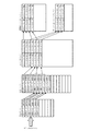
このスロットマシン1は、図1に示すように、3個のリール21a〜21cに表示されている図柄のうち、所定の図柄の組み合わせを所定のライン上に揃えることにより、所定の枚数の遊技メダルを獲得する遊技を提供するものであり、図2に示すように、リール21a〜21cにより図柄を表示する図柄表示手段20と、遊技者の操作を受け付ける操作手段30と、遊技の制御を行う主制御手段100と、遊技に対する演出を行う演出手段40と、この演出手段40を制御する副制御手段200と、から構成されている。
As shown in FIG. 1, the slot machine 1 arranges a predetermined number of game medals by aligning a predetermined combination of symbols among the symbols displayed on the three reels 21a to 21c on a predetermined line. As shown in FIG. 2, a symbol display means 20 for displaying a symbol by reels 21a to 21c, an operation means 30 for receiving an operation of a player, and a main player for controlling the game are provided. It is composed of a control means 100, an effect means 40 for producing an effect on a game, and a sub-control means 200 for controlling the effect means 40.
(主制御手段100)
主制御手段100は、スロットマシン1における遊技の進行や演出等を含む全体を統括制御する手段であり、役の抽選を行うことで当選役を決定する当選役決定手段110、図柄表示手段20の駆動(回転及び停止)制御を行うリール制御手段120、図柄表示手段20が停止したときの図柄の判定を行う入賞判定手段130、入賞時の遊技メダルの払い出し等を制御する払出制御手段140、出玉率に関する設定値を設定する設定値設定手段150、遊技の進行や状態を制御する遊技状態制御手段160、フリーズ演出の実行制御を行うフリーズ制御手段170、操作手段30を構成するストップボタン33a〜33cの押し順を判定する操作順序判定手段175、遊技に関する情報を外部集中端子板80を介して外部機器(例えば、スロットマシン1を管理するホールコンピュータや各々のスロットマシン1の状態を表示する表示装置等)に出力する外部信号送信手段180、主制御手段100から副制御手段200に制御コマンドを送信する制御コマンド送信手段185、及び、第2乱数発生手段190を有して構成されている。この主制御手段100は、図3に示すように、演算等を行うメインCPU(中央演算処理装置)102と、役の抽選や演出(例えば、フリーズ演出等)の抽選等を行うための乱数値を発生させる乱数発生器103と、メインCPU102が各種制御を行うときに、取り込んだデータ等を一時的に記憶しておくRAM104と、遊技の進行等に必要なプログラムを記憶しておくROM105と、副制御手段200と通信を行うI/F回路106と、が主制御基板101上に取り付けられて構成されており、これらはバス107で接続されてデータの送受信が可能に構成されている。この主制御手段100において、メインCPU102は、ROM105に記録された遊技用制御プログラムをRAM104に展開して実行し、遊技の制御を行うように構成されている。なお、メインCPU102には、プログラムの実行で用いる数値等を記憶するレジスタを有しており、以下の説明では、このレジスタを用いた処理について説明するが、これらの処理は一例であって、メインCPU102のレジスタとRAM104とは適宜使用することができる。
(Main control means 100)
The main control means 100 is a means for comprehensively controlling the entire game including the progress and production of the game in the slot machine 1, and the winning combination determining means 110 and the symbol display means 20 for determining the winning combination by drawing a combination. Reel control means 120 for driving (rotation and stop) control, winning determination means 130 for determining a symbol when the symbol display means 20 is stopped, payout control means 140 for controlling payout of game medals at the time of winning, etc. Set value setting means 150 for setting a set value related to a ball rate, a game state control means 160 for controlling the progress and state of a game, a freeze control means 170 for controlling execution of a freeze effect, and stop buttons 33a constituting the operation means 30. Operation order determining means 175 for determining the pressing order of 33c, display of information about the game via an external centralized terminal board 80 to display the status of an external device (for example, a hall computer that manages the slot machine 1 or each slot machine 1). It includes an external signal transmitting means 180 that outputs to a device, etc.), a control command transmitting means 185 that transmits a control command from the main control means 100 to the sub control means 200, and a second random number generating means 190. As shown in FIG. 3, the main control means 100 has a main CPU (central processing unit) 102 that performs calculations and the like, and a random number value for performing lottery of combinations and effects (for example, freeze effects). A random number generator 103 that generates a random number generator 103, a RAM 104 that temporarily stores the captured data and the like when the main CPU 102 performs various controls, and a ROM 105 that stores a program necessary for the progress of the game. An I / F circuit 106 that communicates with the sub-control means 200 is mounted on the main control board 101, and these are connected by a bus 107 so that data can be transmitted and received. In the main control means 100, the main CPU 102 is configured to expand and execute the game control program recorded in the ROM 105 in the RAM 104 to control the game. The main CPU 102 has a register for storing numerical values and the like used in executing a program. In the following description, processing using this register will be described, but these processings are an example and are main. The registers of the CPU 102 and the RAM 104 can be used as appropriate.
この主制御手段100の出力側(図2中、右側)には、図柄表示手段20が電気的に接続されている。この図柄表示手段20は、円筒外周面に沿って多種の図柄が描かれた回転可能な3個のリール21(左リール21a、中リール21b、右リール21c)、リール駆動手段22(左リール駆動手段22a、中リール駆動手段22b、右リール駆動手段22c)、及び、リール位置検出手段23(左リール位置検出手段23a、中リール位置検出手段23b、右リール位置検出手段23c)を有して構成されている。そして、3個のリール21a〜21cが、スロットマシン1の前扉3に形成されたリール表示窓11から、上下に連続する3図柄が見えるように配置されている。よって、これらの左リール21a、中リール21b及び右リール21cは、スロットマシン1のリール表示窓11からは、合計9個の図柄(図1に示す図柄90〜98)が見えるように配置されている。
The symbol display means 20 is electrically connected to the output side (right side in FIG. 2) of the main control means 100. The symbol display means 20 includes three rotatable reels 21 (left reel 21a, middle reel 21b, right reel 21c) and reel driving means 22 (left reel drive) on which various symbols are drawn along the outer peripheral surface of the cylinder. Means 22a, middle reel driving means 22b, right reel driving means 22c), and reel position detecting means 23 (left reel position detecting means 23a, middle reel position detecting means 23b, right reel position detecting means 23c). Has been done. The three reels 21a to 21c are arranged so that three consecutive symbols can be seen from the reel display window 11 formed on the front door 3 of the slot machine 1. Therefore, the left reel 21a, the middle reel 21b, and the right reel 21c are arranged so that a total of nine symbols (designs 90 to 98 shown in FIG. 1) can be seen from the reel display window 11 of the slot machine 1. There is.
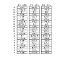
リール21a〜21cの各々には、例えば、図4に示すように0番から19番までの20個の図柄が表示されており、番号が増加する順で変動表示される。なお、この図4に示す図柄及びその配置は一例である。また、図2に示すように、リール駆動手段22(22a〜22c)は、ステッピングモータ等で構成され、リール21(21a〜21c)の各々の回転中心部に連結され、その作動は主制御手段100のリール制御手段120により制御される。さらに、リール位置検出手段23a〜23cは、有効ライン上に表示されている図柄を判定するときに各々のリール21a〜21cの停止位置を決定するためのものであり、このリール位置検出手段23a〜23cによる検出値は主制御手段100により読み出されリール制御手段120や入賞判定手段130により処理される。ここで、各々のリール駆動手段22(22a〜22c)の上方には、リールセンサが配置されている。このリールセンサは、リール21(21a〜21c)の基準となる位置を検知するものであり、リール21(21a〜21c)とリール駆動手段22(22a〜22c)とを連結する部分に取り付けられた被検知部材(インデックス)がこのリールセンサの前を通過したときに、リールセンサでインデックスを検出するように構成されている。これにより、リール21(21a〜21c)が一回転するごとに、それぞれの被検知部材がリールセンサにより検知され、基準となる位置を特定することができ、この基準となる位置に基づいて各々のリール21a〜21cの停止位置を決定することができる。なお、リールセンサとしては、フォトセンサ、磁気センサ、タッチセンサ等を用いることができる。
For example, as shown in FIG. 4, 20 symbols from No. 0 to No. 19 are displayed on each of the reels 21a to 21c, and are displayed in a variable manner in the order in which the numbers increase. The symbols shown in FIG. 4 and their arrangement are examples. Further, as shown in FIG. 2, the reel driving means 22 (22a to 22c) is composed of a stepping motor or the like and is connected to each rotation center portion of the reel 21 (21a to 21c), and its operation is the main control means. It is controlled by the reel control means 120 of 100. Further, the reel position detecting means 23a to 23c are for determining the stop position of each reel 21a to 21c when determining the symbol displayed on the effective line, and the reel position detecting means 23a to 23c The value detected by 23c is read out by the main control means 100 and processed by the reel control means 120 and the winning determination means 130. Here, a reel sensor is arranged above each reel driving means 22 (22a to 22c). This reel sensor detects a reference position of the reels 21 (21a to 21c), and is attached to a portion connecting the reels 21 (21a to 21c) and the reel driving means 22 (22a to 22c). When the detected member (index) passes in front of the reel sensor, the reel sensor is configured to detect the index. As a result, each time the reels 21 (21a to 21c) make one rotation, each member to be detected is detected by the reel sensor, and a reference position can be specified, and each member can be specified based on the reference position. The stop position of the reels 21a to 21c can be determined. As the reel sensor, a photo sensor, a magnetic sensor, a touch sensor, or the like can be used.
また、リール表示窓11から見える9つの図柄のそれぞれの後方に、9個のバックランプ44が配置されている。このバックランプ44を点灯することにより、各図柄を強調表示することができる。あるいは、全てのバックランプ44を点灯し、強調したいライン上のバックランプ44の照度を高くし、強調したくないその他のバックランプ44の照度を低くしてもよい。このように、リール21(21a〜21c)は、複数の図柄が表示された複数の表示領域(リール表示窓11から見える合計9つの図柄の領域)を変動表示させる変動表示手段としての機能を有し、また、バックランプ44は、この変動表示手段の表示領域に対する演出を行う表示領域演出手段としての機能を有している。また、後述する入賞役−A1のようにストップボタン33a〜33cの押し順が割り当てられている役に対してその押し順を演出として報知するときに、後述する無効ライン上にあるバックランプ44を点滅させたり、ストップボタン33a〜33cの停止操作毎に複数ある無効ライン上のバックランプ44を、1ラインずつ消灯させたりするように構成してもよい。
Further, nine back lamps 44 are arranged behind each of the nine symbols that can be seen from the reel display window 11. By turning on the back lamp 44, each symbol can be highlighted. Alternatively, all the back lamps 44 may be turned on to increase the illuminance of the back lamps 44 on the line to be emphasized, and decrease the illuminance of the other back lamps 44 that are not desired to be emphasized. As described above, the reels 21 (21a to 21c) have a function as a variable display means for variablely displaying a plurality of display areas (areas of a total of nine symbols visible from the reel display window 11) on which a plurality of symbols are displayed. Further, the back lamp 44 has a function as a display area effect means for producing an effect on the display area of the variable display means. Further, when the winning combination-A1 described later is notified to the combination to which the pressing order of the stop buttons 33a to 33c is assigned as an effect, the back lamp 44 on the invalid line described later is displayed. It may be configured to blink or to turn off a plurality of back lamps 44 on invalid lines one by one for each stop operation of the stop buttons 33a to 33c.
また、主制御手段100の入力側(図2中、左側)には、操作手段30が電気的に接続されており、この操作手段30はベットボタン31(1ベットボタン31a及びMAXベットボタン31b)、スタートレバー32、ストップボタン33(左ストップボタン33a、中ストップボタン33b、右ストップボタン33c)、清算ボタン34、電源スイッチ35、設定変更キースイッチ36、及び、リセット/設定スイッチ37を有している。
Further, an operating means 30 is electrically connected to the input side (left side in FIG. 2) of the main control means 100, and the operating means 30 is a bet button 31 (1 bet button 31a and MAX bet button 31b). , Start lever 32, stop button 33 (left stop button 33a, middle stop button 33b, right stop button 33c), clearing button 34, power switch 35, setting change key switch 36, and reset / setting switch 37. There is.
スタートレバー32は、図柄表示手段20として設けられたリール21a〜21cを始動させるときに操作するレバーであって、始動手段としての機能を有している。また、ストップボタン33(33a〜33c)は、回転しているリール21a〜21cの各々を停止させるときに遊技者が操作するボタンであって、停止手段としての機能を有している。また、ベットボタン31は、遊技者が貯留メダル(後述する「クレジット」)をスロットマシン1に投入する(ベットする)ときに操作するスイッチであって、その操作によって後述する図柄組み合わせラインが有効化される。なお、図1に示すメダル投入口51は、ベットボタン31と同様に、図柄組み合わせラインを有効化するために遊技メダルを投入する部分であり、このメダル投入口51からの遊技メダルの投入は、ベットボタン31の操作に含まれるものである。なお、1回の単位遊技にベット可能な枚数を超えて遊技メダルが投入された場合には、所定の枚数の範囲内でこのスロットマシン1の内部(遊技媒体貯留手段141)に電子的な情報として貯留される(例えば、RAM104に記憶される)ように構成されている(以下、単に「貯留」と呼ぶ)。また、清算ボタン34は、スロットマシン1の内部に貯留された遊技メダル及びベットされている遊技メダルを払い出すためのボタンである。また、電源スイッチ35は、このスロットマシン1の電源をオン・オフするためのスイッチである。また、設定変更キースイッチ36およびリセット/設定スイッチ37は、後述する設定値設定手段150で設定値を変更するとき等に用いられる。
The start lever 32 is a lever that is operated when starting the reels 21a to 21c provided as the symbol display means 20, and has a function as a starting means. Further, the stop buttons 33 (33a to 33c) are buttons operated by the player when stopping each of the rotating reels 21a to 21c, and have a function as a stop means. Further, the bet button 31 is a switch operated when the player inserts (bets) a stored medal (“credit” described later) into the slot machine 1, and the operation activates the symbol combination line described later. Will be done. The medal insertion slot 51 shown in FIG. 1 is a portion for inserting a game medal in order to activate the symbol combination line, similarly to the bet button 31, and the insertion of the game medal from the medal insertion slot 51 is It is included in the operation of the bet button 31. When a game medal is inserted in excess of the number of bets that can be bet on one unit game, electronic information is electronically stored inside the slot machine 1 (game medium storage means 141) within a predetermined number of cards. It is configured to be stored as (for example, stored in the RAM 104) (hereinafter, simply referred to as "storage"). The clearing button 34 is a button for paying out the game medals stored in the slot machine 1 and the bet game medals. Further, the power switch 35 is a switch for turning on / off the power of the slot machine 1. Further, the setting change key switch 36 and the reset / setting switch 37 are used when the setting value is changed by the setting value setting means 150 described later.
また、この主制御手段100の入力側には、メダル投入口51から投入された遊技メダルを検出するための2つのセンサ(第1投入センサ61及び第2投入センサ62)、遊技メダルを払い出す装置であるホッパー装置から払い出された遊技メダルを検出する払出センサ71、前扉3の開閉を検出するドアスイッチ91、並びに、設定変更キースイッチ36等が格納されたエリアのドアの開閉を検出する設定ドアスイッチ92が接続されている。第1及び第2投入センサ61,62並びに払出センサ71の検出結果は払出制御手段140で処理され、ドアスイッチ91及び設定変更キースイッチ36の検出結果は設定値設定手段150で処理される。なお、メダル投入口51からホッパー装置に連通する流路に対し、上流側に第1投入センサ61が配置され、下流側に第2投入センサ62が配置されている。また、この流路を遊技メダルが流下する過程で、第1及び第2投入センサ61,62が同時に遊技メダルを検出するタイミングがあるように配置されている。
Further, on the input side of the main control means 100, two sensors (first insertion sensor 61 and second insertion sensor 62) for detecting the game medal inserted from the medal insertion slot 51, and the game medal are paid out. Detects the opening and closing of the door in the area where the payout sensor 71 that detects the game medal paid out from the hopper device, the door switch 91 that detects the opening and closing of the front door 3, and the setting change key switch 36 and the like are stored. Setting The door switch 92 is connected. The detection results of the first and second input sensors 61 and 62 and the payout sensor 71 are processed by the payout control means 140, and the detection results of the door switch 91 and the setting change key switch 36 are processed by the set value setting means 150. The first insertion sensor 61 is arranged on the upstream side and the second insertion sensor 62 is arranged on the downstream side with respect to the flow path communicating from the medal insertion port 51 to the hopper device. Further, in the process of the game medals flowing down the flow path, the first and second insertion sensors 61 and 62 are arranged so that there is a timing to detect the game medals at the same time.
また、この主制御手段100の出力側には、メダル投入口51から投入された遊技メダルの流路を決定するセレクタに設けられたブロッカ60、ホッパーモータ70、獲得枚数表示器72及び外部集中端子板80が接続されている。ここで、ブロッカ60は、遊技メダルを受け付けない期間にメダル投入口51から投入されたメダルを返却用の流路に導く機能を有している。また、ホッパーモータ70は、ホッパー装置から遊技メダルを払い出すときに作動する。これらのブロッカ60及びホッパーモータ70の動作は、払出制御手段140により制御される。
Further, on the output side of the main control means 100, a blocker 60, a hopper motor 70, an acquired number display 72, and an external centralized terminal provided in a selector for determining the flow path of game medals inserted from the medal insertion port 51 are provided. The plate 80 is connected. Here, the blocker 60 has a function of guiding the medals inserted from the medal insertion slot 51 to the return flow path during the period when the game medals are not accepted. Further, the hopper motor 70 operates when paying out a game medal from the hopper device. The operations of the blocker 60 and the hopper motor 70 are controlled by the payout control means 140.
(当選役決定手段110)
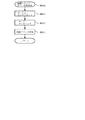
当選役決定手段110は、図3に示す乱数発生器103(以降の説明では、この乱数発生器103を「第1乱数発生手段」とも呼ぶ)から第1の乱数値を取得し、この乱数発生器103とは異なる第2乱数発生手段190から第2の乱数値を取得して、これらの第1の乱数値及び第2の乱数値を演算により処理して第3の乱数値を生成し、この第3の乱数値と、複数の役の各々の当選確率が乱数値の取り得る範囲に対応して定義された役抽選テーブルとにより役に当選したか否かを判定するように構成されている(以下、役抽選テーブルに設定された役毎の当選確率のデータを「確率データ」と呼ぶ)。この当選役決定手段110による当選役の決定方法については後述する。ここで、本実施形態に係るスロットマシン1の役としては、図5に示すように、特別役、入賞役、及び、再遊技役が設けられている。この当選役決定手段110は、何らかの役に当選したときは、後述するフラグ情報記憶手段111に対して当選した役のフラグをオンにする。このように、当選役決定手段110は、当選役を決定し、変動表示手段の表示領域を変動表示させるときに、少なくともその変動表示内容(停止図柄)を決定する役決定手段及び抽選手段としての機能を有している。
(Winning combination determination means 110)
The winning combination determining means 110 acquires a first random number value from the random number generator 103 shown in FIG. 3 (in the following description, the random number generator 103 is also referred to as a “first random number generating means”), and generates the random number. A second random number value is obtained from the second random number generating means 190 different from the device 103, and the first random number value and the second random number value are processed by an operation to generate a third random number value. It is configured to determine whether or not a winning combination has been won by the third random number value and the winning combination lottery table defined corresponding to the range in which the random number values can be won for each of the plurality of winning combinations. (Hereinafter, the winning probability data for each winning combination set in the winning combination lottery table is referred to as "probability data"). The method of determining the winning combination by the winning combination determining means 110 will be described later. Here, as the roles of the slot machine 1 according to the present embodiment, as shown in FIG. 5, a special combination, a winning combination, and a replay combination are provided. When a winning combination is won, the winning combination determining means 110 turns on the flag of the winning combination with respect to the flag information storage means 111 described later. In this way, the winning combination determining means 110 serves as a combination determining means and a lottery means for determining at least the variable display content (stop symbol) when the winning combination is determined and the display area of the variable display means is variablely displayed. It has a function.
ここで、特別役とは、その役に対応する図柄の組み合わせが後述する有効ライン上に停止表示される(入賞する)と、遊技メダルは払い出されないが、特別遊技状態に移行されるという役であり、本実施形態においては、BB(ビックボーナス)としてBB1、BB2、BB3が設けられている。このBBは特別遊技の1つであるBB遊技(いわゆる、第一種特別役物に係る役物連続作動装置が作動する遊技)に移行させる役である。例えば、本実施形態に係るスロットマシン1においては、遊技メダルが3枚ベットされて遊技が行われた場合には、図5に示す特別役(BB1〜BB3)の図柄の組み合わせが有効ライン上に停止表示される(入賞する)と、BB遊技に移行するように構成されている。ここで、BB遊技は、後述するRB遊技を、遊技メダルの払出枚数が所定枚数(例えば、BB1は300枚、BB2は300枚、BB3は450枚)を超えるまで繰り返し行うことができる遊技である。
Here, the special role is a role in which when the combination of symbols corresponding to the role is stopped and displayed (winning) on the effective line described later, the game medal is not paid out, but the game is shifted to the special game state. Therefore, in the present embodiment, BB1, BB2, and BB3 are provided as BBs (big bonuses). This BB is a role of shifting to a BB game (a game in which a so-called first-class special accessory continuous operating device is operated), which is one of the special games. For example, in the slot machine 1 according to the present embodiment, when three game medals are bet and the game is played, the combination of the symbols of the special roles (BB1 to BB3) shown in FIG. 5 is on the effective line. When it is stopped and displayed (winning), it is configured to shift to the BB game. Here, the BB game is a game in which the RB game described later can be repeated until the number of game medals paid out exceeds a predetermined number (for example, 300 for BB1, 300 for BB2, 450 for BB3). ..
なお、特別役はこのBBに限定されることはなく、MB(ミドルボーナス)、RB(レギュラーボーナス)、SB(シングルボーナス)、CB(チャレンジボーナス)等を設けることもできる。MBは特別遊技の1つであるMB遊技(いわゆる、第二種特別役物に係る役物連続作動装置が作動する遊技)に移行させる役である。このMB遊技は、抽選結果に関わらず全ての小役が当選した状態となり、遊技メダルの払出枚数が所定枚数(例えば、30枚)を超えるまで繰り返し行うことができる遊技である。また、このMB遊技においては、後述するリール制御手段120は、3つのリール21a〜21cのうちの少なくとも1つのリールに対して、ストップボタン33(33a〜33c)が押されたときから、1コマ分以内で、そのリール21a〜21cの回転を停止させるよう定められている。このとき、MB遊技においてベットされる遊技メダルの枚数を、MB遊技以外のときとは異なる枚数(例えば2枚)にするように構成することも可能である。また、RBは特別遊技の他の1つであるRB遊技(いわゆる、第一種特別役物に係る条件作動装置が作動する遊技)に移行させる役である。このRB遊技は、所定小役が高確率で当選するボーナスゲームを2回行うか、2回入賞するまで繰り返し行うことができる遊技である。また、SBの図柄の組み合わせが有効ライン上に揃うと、所定小役が高確率で当選するボーナスゲームを1遊技行うSB遊技が行われるが、このSBは遊技状態を制御するための役として用いられることもある。また、CBの図柄の組み合わせが有効ライン上に揃うと、抽選結果に関わらず全ての入賞役が当選した状態となり、1遊技の結果が得られた場合に終了する。このCB遊技において、後述するリール制御手段120は、3つのリール21a〜21cのうちの少なくとも1つのリールに対して、ストップボタン33(33a〜33c)が押されたときから1コマ分以内で、そのリール21a〜21cの回転を停止させるように定められている。
The special role is not limited to this BB, and MB (middle bonus), RB (regular bonus), SB (single bonus), CB (challenge bonus), etc. can be provided. MB is a role of shifting to one of the special games, the MB game (so-called game in which the character continuous operation device related to the second type special accessory is operated). This MB game is a game in which all small wins are won regardless of the lottery result, and can be repeated until the number of game medals paid out exceeds a predetermined number (for example, 30). Further, in this MB game, the reel control means 120, which will be described later, has one frame since the stop button 33 (33a to 33c) is pressed on at least one of the three reels 21a to 21c. It is stipulated that the rotation of the reels 21a to 21c is stopped within a minute. At this time, it is also possible to configure the number of game medals bet in the MB game to be different from the number (for example, two) bet in the game other than the MB game. Further, the RB is a role of shifting to the RB game (a game in which the condition operating device related to the so-called first-class special accessory is operated), which is one of the special games. This RB game is a game in which a bonus game in which a predetermined small winning combination is won with a high probability is played twice or can be repeatedly played until a prize is won twice. In addition, when the combination of SB symbols is aligned on the effective line, an SB game is performed in which one bonus game in which a predetermined small winning combination is won with a high probability is performed, and this SB is used as a role for controlling the gaming state. It may be done. In addition, when the combinations of CB symbols are aligned on the effective line, all the winning combinations are won regardless of the lottery result, and the game ends when the result of one game is obtained. In this CB game, the reel control means 120, which will be described later, is within one frame from the time when the stop button 33 (33a to 33c) is pressed for at least one of the three reels 21a to 21c. It is defined to stop the rotation of the reels 21a to 21c.
また、入賞役とは、その図柄の組み合わせが有効ライン上に停止表示されると、予め定められた枚数の遊技メダルが払い出される役であり、図5に示すように、入賞役の種類に応じて、その役に対応する図柄の組み合わせ及び払い出される遊技メダルの枚数が設定されている。この本実施形態に係るスロットマシン1においては、入賞役として入賞役01〜48が設定されている。また、再遊技役(リプレイ)とは、この再遊技役の図柄の組み合わせが有効ライン上に停止表示された遊技で、投入したメダル枚数を維持して再度遊技が行えるようにした役である。本実施形態に係るスロットマシン1においては、図5に示すように再遊技役01〜11が設定されている。なお、再遊技役の図柄の組み合わせが有効ライン上に停止表示された次の遊技においても、メダル投入口51からの遊技メダルの投入は可能である。
Further, the winning combination is a combination in which a predetermined number of game medals are paid out when the combination of the symbols is stopped and displayed on the valid line, and as shown in FIG. 5, depending on the type of winning combination. Therefore, the combination of symbols corresponding to the combination and the number of game medals to be paid out are set. In the slot machine 1 according to this embodiment, winning combinations 01 to 48 are set as winning combinations. Further, the replay combination is a game in which the combination of the symbols of the replay combination is stopped and displayed on the effective line, and the number of medals inserted is maintained so that the game can be played again. In the slot machine 1 according to the present embodiment, the replay combinations 01 to 11 are set as shown in FIG. In the next game in which the combination of symbols of the re-game combination is stopped and displayed on the effective line, the game medal can be inserted from the medal insertion slot 51.
この当選役決定手段110は、図2に示すように、抽選結果等を記憶するフラグ情報記憶手段111、及び、当選役決定手段110で特別役に当選したときに、後述する有効ライン上に対応する図柄の組み合わせが停止表示されるまで(入賞するまで)当選した状態を保持する特別役持ち越し手段112を有している。
As shown in FIG. 2, the winning combination determining means 110 corresponds to the flag information storing means 111 for storing the lottery result and the like, and when the winning combination determining means 110 wins a special combination, it corresponds to the effective line described later. It has a special role carry-over means 112 that holds the winning state until the combination of symbols to be played is stopped and displayed (until a prize is won).
(フラグ情報記憶手段111)
フラグ情報記憶手段111は、当選役決定手段110によって何らかの役に当選したとき(後述するように、当選した役の条件装置検索番号が条件装置番号バッファに設定されたとき)に、当選した役の種類及びそのフラグをオンにして記憶する。なお、特別役を有するスロットマシンにおいては、フラグ情報記憶手段111に記憶されている情報が消去されるタイミング(当選フラグがオフとなるタイミング)は、特別役とそれ以外の役とで異なっている。すなわち、特別役の場合、フラグ情報記憶手段111に記憶されている情報は、特別役の図柄の組み合わせが有効ライン上に停止表示されたことを条件として消去され、特別役の図柄の組み合わせが有効ライン上に停止表示されなければ次遊技以降、当該図柄の組み合わせが有効ライン上に停止表示されるまで持ち越されるのに対し、それ以外の役の場合には、その役に対する図柄の組み合わせが有効ライン上に停止表示されるか否かに関わらず、当該遊技の終了の際に消去され、次遊技まで持ち越されることはない。なお、MB遊技を有するスロットマシン1においては、MB遊技中は、当選役決定手段110の抽選結果に拘わらず、特別役を除く全ての払い出しを有する役の当選フラグをオンすることができる。但し、抽選結果で再遊技役(リプレイ)が当選したときは、その再遊技役のフラグをオンにするように構成してもよい。このように、フラグ情報記憶手段111は、当選役決定手段110で決定された役を記憶する決定役記憶手段としての機能を有している。
(Flag information storage means 111)
When the flag information storage means 111 wins a winning combination by the winning combination determining means 110 (as will be described later, when the conditional device search number of the winning combination is set in the conditional device number buffer), the winning combination Turn on the type and its flag and memorize it. In the slot machine having a special role, the timing at which the information stored in the flag information storage means 111 is deleted (the timing at which the winning flag is turned off) differs between the special role and the other roles. .. That is, in the case of a special combination, the information stored in the flag information storage means 111 is deleted on condition that the combination of the symbols of the special combination is stopped and displayed on the valid line, and the combination of the symbols of the special combination is valid. If it is not stopped and displayed on the line, it will be carried over from the next game until the combination of the symbols is stopped and displayed on the valid line, but in the case of other combinations, the combination of symbols for that combination is the valid line. Regardless of whether or not it is stopped and displayed above, it will be deleted at the end of the game and will not be carried over to the next game. In the slot machine 1 having the MB game, during the MB game, regardless of the lottery result of the winning combination determining means 110, the winning flag of the combination having all payouts except the special combination can be turned on. However, when the replay is won in the lottery result, the flag of the replay may be turned on. As described above, the flag information storage means 111 has a function as a determination combination storage means for storing the combination determined by the winning combination determination unit 110.
(特別役持ち越し手段112)
特別役持ち越し手段112は、当選役決定手段110により特別役に当選し、フラグ情報記憶手段111に、この特別役に対するフラグが立てられると、当選した特別役の図柄の組み合わせが有効ライン上に停止表示されるまで、その当選役を持ち越し(フラグが立てられた状態を維持し)、特別役の図柄の組み合わせが有効ライン上に停止表示されると特別役の持ち越しを終了する(フラグが下げられる)。なお、特別役のうちSB及びCBは、当選した遊技で図柄を停止表示させることができないと、フラグは下げられる(次遊技に持ち越すことはできない)。また、特別役を持ち越し中(後述する内部中遊技状態であるRT4遊技状態にあるとき)に、当選役決定手段110による役抽選の結果、入賞役が当選したときは、特別役と入賞役のフラグが立っている状態であり、停止態様によって当選フラグのうちのいずれかの図柄の組み合わせを有効ライン上に停止表示させることができる。
(Special role carry-over means 112)
When the special role carry-over means 112 is elected as a special role by the winning combination determining means 110 and the flag information storage means 111 is flagged for this special role, the combination of the symbols of the winning special role is stopped on the valid line. The winning combination is carried over (maintained in the flagged state) until it is displayed, and when the combination of special role symbols is stopped and displayed on the valid line, the carry-over of the special role is terminated (the flag is lowered). ). Of the special roles, SB and CB will be flagged if the symbol cannot be stopped and displayed in the winning game (the flag cannot be carried over to the next game). In addition, when the winning combination is won as a result of the combination lottery by the winning combination determining means 110 while the special role is being carried over (when the RT4 gaming state is in the internal medium gaming state described later), the special role and the winning combination are selected. The flag is set, and the combination of any of the winning flags can be stopped and displayed on the valid line depending on the stop mode.
(リール制御手段120)
リール制御手段120は、操作手段30のスタートレバー32及びストップボタン33a〜33cが操作されたタイミングに応じて、リール21a〜21cの回転の開始及び停止の制御を行う。より具体的には、リール制御手段120は、スタートレバー32が操作されると、リール21a〜21cを回転させ、その後、ストップボタン33a〜33cが操作される毎に、後述する遊技状態制御手段160で管理されている遊技状態、当選役決定手段110による抽選の結果、並びに、ストップボタン33(左ストップボタン33a、中ストップボタン33b、右ストップボタン33c)が操作されたタイミングに基づいて、当該操作がされたストップボタン33a〜33cに対応するリール21a〜21cの停止位置を決定すると共に、リール駆動手段(ステッピングモータ)22a〜22cの駆動を制御して、その決定した位置でリール21a〜21cの各々を停止させる。このように、リール制御手段120は、複数の図柄が表示された表示領域を変動表示させる変動表示手段としてのリール21a〜21cを、停止手段であるストップボタン33a〜33cの操作に応じて停止させる変動表示制御手段の機能を有している。
(Reel control means 120)
The reel control means 120 controls the start and stop of rotation of the reels 21a to 21c according to the timing when the start lever 32 and the stop buttons 33a to 33c of the operation means 30 are operated. More specifically, the reel control means 120 rotates the reels 21a to 21c when the start lever 32 is operated, and then every time the stop buttons 33a to 33c are operated, the gaming state control means 160 described later is performed. Based on the game state managed in, the result of the lottery by the winning combination determining means 110, and the timing at which the stop buttons 33 (left stop button 33a, middle stop button 33b, right stop button 33c) are operated. The stop positions of the reels 21a to 21c corresponding to the stopped buttons 33a to 33c are determined, and the driving of the reel driving means (stepping motors) 22a to 22c is controlled, and the reels 21a to 21c are moved at the determined positions. Stop each. In this way, the reel control means 120 stops the reels 21a to 21c as the variable display means for variablely displaying the display area on which a plurality of symbols are displayed in response to the operation of the stop buttons 33a to 33c which are the stop means. It has the function of a variable display control means.
ここで、スロットマシン1のリール表示窓11に表示されているリール21a〜21cには、図柄組み合わせラインが設けられている。この「図柄組み合わせライン」とは、リール21a〜21cの停止時における図柄の並びラインであって、図柄の組み合わせを形成させるラインである。例えば、本実施形態では、図1に示すように、リール表示窓11に表示される3×3の9個の図柄停止位置90〜98に対して、それぞれのリール21a〜21cから1個ずつの図柄停止位置を選択してそれらを結ぶラインとして構成される。
Here, the reels 21a to 21c displayed on the reel display window 11 of the slot machine 1 are provided with a symbol combination line. The "symbol combination line" is a line for arranging symbols when the reels 21a to 21c are stopped, and is a line for forming a combination of symbols. For example, in the present embodiment, as shown in FIG. 1, one from each reel 21a to 21c is used for nine 3 × 3 symbol stop positions 90 to 98 displayed on the reel display window 11. It is configured as a line connecting the symbol stop positions by selecting them.
さらに、これらの図柄組み合わせラインの中から、有効ラインと無効ラインとが設定される。「有効ライン」とは、本実施形態では、いずれかの役に対応する図柄の組み合わせがそのライン上に停止表示されたときに、入賞と判定されその役に応じた利益が遊技者に付与されるラインである。一方、「無効ライン」とは、図柄組み合わせラインのうち、有効ラインとして設定されないラインであって、いずれかの役に対応する図柄の組み合わせがそのライン上に停止表示された場合であっても、その役に応じた利益の付与(遊技メダルの払い出し等)を行わないラインである。すなわち、無効ラインは、そもそも図柄の組み合わせの成立対象となっていないラインである。これらの有効ライン及び無効ラインは、遊技者によって投入された遊技メダルの枚数に応じて設定されるように構成することもできるし、予め決めておくこともできる。なお、本実施形態に係るスロットマシン1では、図1に示すように、左リール21aの中段の図柄停止位置91、中リール21bの中段の図柄停止位置94、及び、右リール21cの中段の図柄停止位置97を結ぶラインLが有効ラインとして設定されている。なお、この図柄組み合わせラインの構成は一例であって、本発明がこの構成に限定されることはない。
Further, a valid line and an invalid line are set from these symbol combination lines. In the present embodiment, the "effective line" means that when a combination of symbols corresponding to any of the combinations is stopped and displayed on the line, it is determined that the player has won a prize and a profit corresponding to the combination is given to the player. Line. On the other hand, the "invalid line" is a line that is not set as a valid line among the symbol combination lines, and even if the combination of symbols corresponding to any of the combinations is stopped and displayed on the line. It is a line that does not give profits (such as paying out game medals) according to the role. That is, the invalid line is a line that is not the target of establishing the combination of symbols in the first place. These valid lines and invalid lines can be configured to be set according to the number of game medals inserted by the player, or can be determined in advance. In the slot machine 1 according to the present embodiment, as shown in FIG. 1, the symbol stop position 91 in the middle of the left reel 21a, the symbol stop position 94 in the middle of the middle reel 21b, and the symbol in the middle of the right reel 21c. The line L connecting the stop positions 97 is set as an effective line. The configuration of this symbol combination line is an example, and the present invention is not limited to this configuration.
上述したリール駆動手段22a〜22cの各々を構成するステッピングモータは、特に図示していないが、主制御手段100から供給される駆動パルスにより励磁する4相のコイル(固定子)を有している。そして、4相のコイルのうち、同時に2つの相が励磁した状態となる2相励磁と、4相のコイルのうちの1つの相が励磁した状態となる1相励磁とが交互に繰り返される1−2相励磁により、ローター(回転子)が回転するように構成されている。また、このステッピングモータにはリール21a〜21cの制御用に所定のステップ数が定められており、リール21a〜21cの各図柄に対してステップ数を割り当てることで、1図柄単位での停止を制御するように構成されている。
Although not particularly shown, the stepping motors constituting each of the reel driving means 22a to 22c described above have a four-phase coil (stator) excited by a driving pulse supplied from the main control means 100. .. Then, two-phase excitation in which two of the four-phase coils are excited at the same time and one-phase excitation in which one of the four-phase coils is excited are alternately repeated. The rotor is configured to rotate by two-phase excitation. Further, the stepping motor has a predetermined number of steps for controlling the reels 21a to 21c, and by assigning the number of steps to each symbol of the reels 21a to 21c, the stop in one symbol unit is controlled. It is configured to do.
ここで、本実施形態に係るスロットマシン1が有するステッピングモータ(リール駆動手段22a〜22c)におけるステップ数の割り当てについて説明する。このステッピングモータは、全ステップ数として例えば336ステップ(=21×16)が設定され、かつ、定速状態の回転速度が80rpmとなっている。また、このスロットマシン1では、ストップボタン33a〜33cが操作された時点から所定の時間Ts(例えば、190ms)以内に、かつ、当該時点から最大5個の図柄の範囲内で、リール21a〜21cの回転を停止させるように構成されている。
Here, the allocation of the number of steps in the stepping motors (reel driving means 22a to 22c) included in the slot machine 1 according to the present embodiment will be described. In this stepping motor, for example, 336 steps (= 21 × 16) are set as the total number of steps, and the rotation speed in the constant speed state is 80 rpm. Further, in the slot machine 1, the reels 21a to 21c are within a predetermined time Ts (for example, 190 ms) from the time when the stop buttons 33a to 33c are operated, and within the range of a maximum of five symbols from that time. It is configured to stop the rotation of.
例えば、リール21a〜21cとして、周囲に21個の図柄が配置されたリールを使用する場合には、各図柄に対して、均等に16ステップを割り当てることができる。そして、上述したように、ステッピングモータの回転速度は80rpmであることから、1ステップ当たりの制御時間は2.23msとなる。すると、ストップボタン33a〜33cの各々が操作された時点から最大で5図柄先で停止させるとすると、5図柄分のステップ数は80ステップ(=16×5)であるため、ストップボタン33a〜33cが操作されてから対応するリール21a〜21cが停止するまでの時間は、178.4ms(=2.23×80)となる。なお、ストップボタン33a〜33cの操作タイミングによっては、1ステップ分、遅れて停止の処理が行われる可能性があるが、これを考慮しても、ストップボタン33a〜33cが操作されてから対応するリール21a〜21cが停止するまでの時間は、最大で180.63ms(=178.4+2.23)となり、190ms以内に収めることができる。
For example, when reels 21a to 21c in which 21 symbols are arranged around each reel are used, 16 steps can be evenly assigned to each symbol. As described above, since the rotation speed of the stepping motor is 80 rpm, the control time per step is 2.23 ms. Then, assuming that each of the stop buttons 33a to 33c is stopped at a maximum of 5 symbols from the time when each of them is operated, the number of steps for the 5 symbols is 80 steps (= 16 × 5), so the stop buttons 33a to 33c The time from the operation of the reels 21a to 21c until the corresponding reels 21a to 21c are stopped is 178.4 ms (= 2.23 × 80). Depending on the operation timing of the stop buttons 33a to 33c, the stop processing may be delayed by one step, but even if this is taken into consideration, it corresponds after the stop buttons 33a to 33c are operated. The maximum time required for the reels 21a to 21c to stop is 180.63 ms (= 178.4 + 2.23), which can be kept within 190 ms.
しかし、本実施形態に係るスロットマシン1のリール21a〜21cには、上述したように、周囲に20個の図柄が表示されており、各図柄に対して均等にステップ数を割り当てることができない。また、21個の場合よりも図柄の数が1個減ることにより、割り当てられるステップ数が多くなる図柄が必要となるため、ステップ数の割り当てが偏ると、ストップボタン33a〜33cが操作された時点から最大で5図柄先で停止させようとした場合、190ms以内に停止させることができなくなるおそれがある。そのため、本実施形態に係るスロットマシン1では、全ステップ数として設定されている336ステップを20で除算したときの商M(すなわち16)及び余りP(すなわち16)に基づき、20個の図柄のうち、連続する5個の図柄の範囲のいずれにもM+1ステップ(すなわち、17ステップ)を割り当てたP/4個(すなわち、4個)の図柄と、Mステップ(すなわち、16ステップ)を割り当てた(20−P)/4個(すなわち、1個)の図柄とが含まれるように構成している。具体的には、17ステップ、17ステップ、17ステップ、16ステップ、17ステップという並びを4回繰り返すように、リール21a〜21cの各図柄に対してステップ数を割り当てている。
However, as described above, 20 symbols are displayed around the reels 21a to 21c of the slot machine 1 according to the present embodiment, and the number of steps cannot be evenly assigned to each symbol. In addition, since the number of symbols is reduced by one compared to the case of 21, a symbol that increases the number of assigned steps is required. Therefore, if the allocation of the number of steps is biased, the time when the stop buttons 33a to 33c are operated. If you try to stop at a maximum of 5 symbols, you may not be able to stop within 190 ms. Therefore, in the slot machine 1 according to the present embodiment, there are 20 symbols based on the quotient M (that is, 16) and the remainder P (that is, 16) when the 336 steps set as the total number of steps are divided by 20. Of these, P / 4 (ie, 4) symbols to which M + 1 steps (that is, 17 steps) were assigned to any of the range of 5 consecutive symbols and M steps (that is, 16 steps) were assigned. It is configured to include (20-P) / 4 (that is, 1) symbols. Specifically, the number of steps is assigned to each symbol of the reels 21a to 21c so that the sequence of 17 steps, 17 steps, 17 steps, 16 steps, and 17 steps is repeated four times.
このように各リール21a〜21cにステップ数を割り当てることにより、20個の図柄のうち、いずれの連続する5個の範囲においても17ステップが割り当てられた4個と16ステップが割り当てられた1個が含まれることとなるため、5個の図柄の範囲におけるステップ数の合計は84ステップ(=17×4+16)となり、停止時間を190ms以内に収めることができる。
By allocating the number of steps to each reel 21a to 21c in this way, 4 out of 20 symbols to which 17 steps are assigned and 1 to which 16 steps are assigned in any of 5 consecutive ranges. Is included, the total number of steps in the range of 5 symbols is 84 steps (= 17 × 4 + 16), and the stop time can be kept within 190 ms.
また、上述したように、当選役決定手段110で決定される役に特別役が含まれるスロットマシン1のリール制御手段120は、特別役に当選し、特別役持ち越し手段112によりその特別役が持ち越されている遊技において、入賞役や再遊技役に当選しているときは、これらの役を優先して有効ライン上に停止させるようにリール21a〜21cの作動を制御するように構成することができる。具体的には、再遊技役が当選しているときは他の当選役に優先して必ずこの再遊技役の図柄の組み合わせが有効ライン上に停止表示される。また、入賞役については、特別役に優先して図柄の組み合わせが有効ライン上に停止表示するように構成することができる。なお、このようなリール21a〜21cを停止させる際の制御は、後述するようにリール制御用の停止テーブルを用いて行われる。
Further, as described above, the reel control means 120 of the slot machine 1 in which the special combination is included in the combination determined by the winning combination determining means 110 is elected as a special combination, and the special combination is carried over by the special combination carry-over means 112. In the games that have been played, when a winning combination or a re-game combination is won, the operation of the reels 21a to 21c may be controlled so as to give priority to these combinations and stop them on the effective line. it can. Specifically, when the re-game combination is won, the combination of the symbols of the re-game combination is always stopped and displayed on the effective line in preference to the other winning combinations. Further, the winning combination can be configured so that the combination of symbols is stopped and displayed on the effective line in preference to the special combination. It should be noted that such control when stopping the reels 21a to 21c is performed using a stop table for reel control as described later.
また、リール制御手段120は、前の遊技と次の遊技との間隔が所定の時間(最小遊技時間)T0以上になるようにリール21a〜21cの作動を制御するように構成されている。すなわち、スタートレバー32が操作されてリール21a〜21cが回転を開始したときから最小遊技時間T0が経過した後に次の遊技が開始されたとき(スタートレバー32が操作されたとき)は、そのスタートレバー32の操作に応じてリール21a〜21cの回転を開始させる。しかし、最小遊技時間T0が経過する時刻より前の時刻においてスタートレバー32が操作されたときは、リール制御手段120は、スタートレバー32が操作された時点ではリール21a〜21cの回転は開始させず、最小遊技時間T0が経過した時点においてリール21a〜21cの回転を開始させる。なお、この最小遊技時間T0としては、例えば、4.1秒が設定される。
Further, the reel control means 120 is configured to control the operation of the reels 21a to 21c so that the interval between the previous game and the next game is T0 or more for a predetermined time (minimum game time). That is, when the next game is started after the minimum game time T0 has elapsed from the time when the start lever 32 is operated and the reels 21a to 21c start rotating (when the start lever 32 is operated), the start is started. The rotation of the reels 21a to 21c is started according to the operation of the lever 32. However, when the start lever 32 is operated at a time before the time when the minimum game time T0 elapses, the reel control means 120 does not start the rotation of the reels 21a to 21c when the start lever 32 is operated. , The rotation of the reels 21a to 21c is started when the minimum game time T0 has elapsed. As the minimum game time T0, for example, 4.1 seconds is set.
ここで、本実施形態に係るスロットマシン1において、入賞役は、上述したように入賞役01〜48の48個の役から構成されている。この入賞役01〜48は、図5に示すようにそれぞれの図柄の組み合わせが異なるように構成されている。なお、図5において、左中右の各リールに停止する図柄をこの順でカギ括弧(「」)でくくって表示しており、一つのカギ括弧内でスラッシュ(/)で区切られた図柄は、それぞれの図柄が当該役を構成していることを示している。例えば、図5において、入賞役01の図柄の組み合わせは「リプレイ」−「ベル1/ベル2」−「リプレイ」と表記されているが、これは、「リプレイ」−「ベル1」−「リプレイ」(左リール21aの中段に「リプレイ」の図柄が停止表示され、中リール21bの中段に「ベル1」の図柄が停止表示され、右リール21cの中段に「リプレイ」の図柄が停止表示されている状態)と、「リプレイ」−「ベル2」−「リプレイ」(左リール21aの中段に「リプレイ」の図柄が停止表示され、中リール21bの中段に「ベル2」の図柄が停止表示され、右リール21cの中段に「リプレイ」の図柄が停止表示されている状態)と、を含むことを示している。この入賞役01のように、本実施形態に係るスロットマシン1は、それぞれの役に対して複数の図柄の組み合わせが対応付けられている場合がある。この場合、何れかの図柄の組み合わせが有効ライン上に停止表示されると、当該役に入賞したものと判断される。なお、入賞役44及び入賞役45の右リール21cの図柄として示す「any」は、この右リール21cに配置された図柄のいずれでもよいことを示している。
Here, in the slot machine 1 according to the present embodiment, the winning combination is composed of 48 combinations of winning combinations 01 to 48 as described above. As shown in FIG. 5, the winning combinations 01 to 48 are configured so that the combination of the respective symbols is different. In FIG. 5, the symbols that stop on each of the left, middle, and right reels are enclosed in brackets ("") in this order, and the symbols separated by slashes (/) within one bracket are displayed. , Indicates that each symbol constitutes the role. For example, in FIG. 5, the combination of the symbols of the winning combination 01 is described as "replay"-"bell 1 / bell 2"-"replay", which is "replay"-"bell 1"-"replay". (The "Replay" symbol is stopped and displayed in the middle of the left reel 21a, the "Bell 1" symbol is stopped and displayed in the middle of the middle reel 21b, and the "Replay" symbol is stopped and displayed in the middle of the right reel 21c. (While) and "Replay"-"Bell 2"-"Replay" (the "Replay" symbol is stopped and displayed in the middle of the left reel 21a, and the "Bell 2" symbol is stopped and displayed in the middle of the middle reel 21b. (A state in which the "replay" symbol is stopped and displayed in the middle of the right reel 21c) and. Like the winning combination 01, the slot machine 1 according to the present embodiment may have a combination of a plurality of symbols associated with each combination. In this case, if any combination of symbols is stopped and displayed on the valid line, it is determined that the winning combination has been won. In addition, "any" shown as a symbol of the right reel 21c of the winning combination 44 and the winning combination 45 indicates that any of the symbols arranged on the right reel 21c may be used.
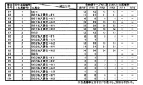
また、この入賞役01〜48に対しては、図8に示すように、これらの入賞役01〜48を組み合わせた(重複当選されるように構成された)58個の当選役が割り当てられている(入賞役−A1〜入賞役−I)。この図8において、当選役の括弧内は、当選役である入賞役に割り当てられた入賞役01〜48を示し、例えば、当選役として入賞役−A1が決定されたときは、入賞役01、入賞役03、入賞役07、入賞役08、入賞役09、入賞役10、入賞役23及び入賞役29が重複して当選することを示している。また、入賞役−Iは、上述したBB遊技が実行されているときに当選する役であり、入賞役01〜48の全てが当選する役である。このように、本実施形態においては、入賞役を含む当選役においては、上述したように入賞役が重複当選する構成と、入賞役−F2、入賞役−H1、H2のように、いずれかの入賞役が単独当選する構成と、を有している。
Further, as shown in FIG. 8, 58 winning combinations (configured to be duplicated) in which these winning combinations 01 to 48 are combined are assigned to the winning combinations 01 to 48. Yes (winning combination-A1-winning combination-I). In FIG. 8, the winning combination in parentheses indicates the winning combination 01 to 48 assigned to the winning combination. For example, when the winning combination-A1 is determined as the winning combination, the winning combination 01, It indicates that the winning combination 03, the winning combination 07, the winning combination 08, the winning combination 09, the winning combination 10, the winning combination 23, and the winning combination 29 are duplicated. Further, the winning combination-I is a combination of winning when the above-mentioned BB game is being executed, and all of the winning combinations 01 to 48 are winning. As described above, in the present embodiment, in the winning combination including the winning combination, the winning combination is duplicated as described above, and any one of the winning combination-F2, the winning combination-H1, and H2. It has a structure in which the winning combination is won independently.
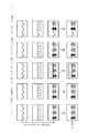
そして、図10に示すように、これらの当選役のうち、入賞役−A1〜A12、入賞役−B1〜B12、入賞役C1〜C12、及び、入賞役D1〜D12に対して、ストップボタン33a〜33cの押し順が割り当てられている。以下、これらの押し順が割り当てられた入賞役を「押し順ベル」と呼ぶ。これらの押し順ベルにおいて、ストップボタン33a〜33cの操作タイミングに関わらず、必ず入賞役の図柄の組み合わせが有効ライン上に停止表示される押し順(図10において「○」が示されている押し順)を「正解押し順」と呼ぶ。この図10(a)において、たとえば「左中右」は、第1停止として左ストップボタン33aが操作され、第2停止として中ストップボタン33bが操作され、第3停止として右ストップボタン33cが操作される場合を示している。ここで、3つのストップボタン33a〜33cに対する押し順は6通りあるが、本実施形態に係るスロットマシン1においては、第1停止として左ストップボタン33a又は中ストップボタン33bを操作する押し順(左中右、左右中、中左右、中右左の4通りの押し順)に対して正解押し順が割り当ている。なお、図10の○又は△の符号に付随して示されている括弧内の数字は、停止表示される入賞役を示している。例えば、図10における入賞役−A1において左中右の順でストップボタン33a〜33cが操作されたときは、入賞役01の図柄の組み合わせが有効ライン上に停止表示されることを示している。
Then, as shown in FIG. 10, among these winning combinations, the stop buttons 33a are used for the winning combinations-A1 to A12, the winning combinations-B1 to B12, the winning combinations C1 to C12, and the winning combinations D1 to D12. The push order of ~ 33c is assigned. Hereinafter, the winning combination to which these push orders are assigned will be referred to as a "push order bell". In these push order bells, regardless of the operation timing of the stop buttons 33a to 33c, the combination of the winning combination symbols is always displayed as a stop on the valid line. The order) is called the "correct answer pressing order". In FIG. 10A, for example, in "left middle right", the left stop button 33a is operated as the first stop, the middle stop button 33b is operated as the second stop, and the right stop button 33c is operated as the third stop. It shows the case where it is done. Here, there are six push orders for the three stop buttons 33a to 33c, but in the slot machine 1 according to the present embodiment, the push order for operating the left stop button 33a or the middle stop button 33b as the first stop (left). The correct push order is assigned to the four push orders (middle right, left and right middle, middle left and right, middle right and left). In addition, the number in parentheses shown by the reference numeral of ◯ or Δ in FIG. 10 indicates a winning combination that is stopped and displayed. For example, when the stop buttons 33a to 33c are operated in the order of left, middle, and right in the winning combination-A1 in FIG. 10, it is shown that the combination of the symbols of the winning combination 01 is stopped and displayed on the effective line.
上述したように、リール制御手段120は、ストップボタン33a〜33cの各々が操作されると、対応するリール21a〜21cを、その操作がされたときに、リール表示窓11の中段に相当する位置にある図柄を含めて5図柄以内に停止させるリール制御を行うように構成されている。図4に示すように、本実施形態に係るスロットマシン1では、左リール21a及び右リール21cの何れにおいても、「リプレイ」の図柄は、互いの間隔が5図柄以内になるように配置されている(中リール21bも同様である)。また、中リール21bは、5図柄以内に「ベル1」、「ベル2」の図柄のいずれかが配置されている。すなわち、中ストップボタン33bがどのようなタイミングで操作されても中リール21bの有効ライン上に「ベル1」、「ベル2」の図柄のいずれかを引き込んで停止表示させることができる。したがって、図10に示す入賞役−A1に当選したときに、ストップボタン33a〜33cが「左中右」の順で操作されたときは、ストップボタン33a〜33cがどのようなタイミングで操作されても有効ライン上に左から順に「リプレイ」−「ベル1/ベル2」−「リプレイ」の図柄を引き込んで停止表示させることができる。したがって、これらのリール21a〜21cの各々がどのような回転位置にあったとしても、入賞役−A1の当選に対してストップボタン33a〜33cに対して正解押し順で操作がされると、リール制御手段120は、有効ライン上に、入賞役01を構成する複数の図柄の組み合わせの何れかを有効ライン上に停止表示させることができる。
As described above, when each of the stop buttons 33a to 33c is operated, the reel control means 120 moves the corresponding reels 21a to 21c to a position corresponding to the middle stage of the reel display window 11. It is configured to perform reel control to stop within 5 symbols including the symbols in. As shown in FIG. 4, in the slot machine 1 according to the present embodiment, in both the left reel 21a and the right reel 21c, the symbols of "replay" are arranged so that the distance between them is within 5 symbols. (The same applies to the middle reel 21b). Further, in the middle reel 21b, any of the symbols "bell 1" and "bell 2" is arranged within 5 symbols. That is, no matter what timing the middle stop button 33b is operated, either the "bell 1" or "bell 2" symbol can be pulled into the effective line of the middle reel 21b to display the stop. Therefore, when the winning combination-A1 shown in FIG. 10 is won and the stop buttons 33a to 33c are operated in the order of "left middle right", the stop buttons 33a to 33c are operated at what timing. You can also pull in the "Replay"-"Bell 1 / Bell 2"-"Replay" symbols on the effective line in order from the left to stop and display them. Therefore, no matter what rotation position each of these reels 21a to 21c is in, if the stop buttons 33a to 33c are operated in the correct pressing order for winning the winning combination-A1, the reels are operated. The control means 120 can stop and display any combination of a plurality of symbols constituting the winning combination 01 on the effective line.
なお、正解押し順以外の押し順(以下、「不正解押し順」と呼ぶ)でストップボタン33a〜33cが操作されたときは、上述したリール制御に基づいて、当選役に含まれる入賞役の図柄の組み合わせを有効ライン上に引き込むことができるときはこの図柄の組み合わせを停止表示させ、引き込むことができないときは後述する特定図柄の組み合わせが停止表示される(図10において「△」が示されている押し順)。
When the stop buttons 33a to 33c are operated in a pressing order other than the correct pressing order (hereinafter referred to as "incorrect answer pressing order"), the winning combination included in the winning combination is based on the reel control described above. When the combination of symbols can be drawn on the effective line, this combination of symbols is stopped and displayed, and when it cannot be drawn, the combination of specific symbols described later is stopped and displayed (“Δ” is shown in FIG. 10). Pushing order).
さらに、第1停止として右ストップボタン33cを操作する押し順(右左中及び右中左の2通り)については、図10に示すように、右リール21cに対して「赤7」、「青7」、「黒バー」、「白ブランク」のいずれかの図柄が割り当てられている。例えば、入賞役−A1〜A3に対しては「赤7」の図柄が割り当てられており、これらの役が当選した遊技において、回転している右リール21cに対して、第1停止として右ストップボタン33cが操作されたときは、上述したリール制御に基づいて「赤7」の図柄を有効ライン上に引き込むことができるときは、この図柄を有効ライン上に停止表示させるように構成されている。図4から明らかなように、右リール21cにおいては、5図柄毎に「赤7」、「青7」、「黒バー」、「白ブランク」が配置されている。従って、遊技者は、当選役に割り当てられた図柄を狙って右ストップボタン33cを操作することで(いわゆる「目押し」を行うことで)、有効ライン上にこれらの図柄を停止表示させることができる。具体的には、割り当てられた図柄(例えば「赤7」)が有効ラインを通過する前の5つの図柄のいずれかが有効ライン上にあるときに右ストップボタン33cを操作するとその割り当てられた図柄が有効ライン上に引き込まれるように構成されている(割り当てられた図柄を「目押しで狙う色又は図柄」と呼ぶ)。
Further, as for the pressing order (two ways of right / left middle and right middle left) for operating the right stop button 33c as the first stop, as shown in FIG. 10, “red 7” and “blue 7” with respect to the right reel 21c. , "Black bar", or "white blank" is assigned. For example, the winning combination-A1 to A3 are assigned the symbol "Red 7", and in the game in which these combinations are won, the rotating right reel 21c is stopped right as the first stop. When the button 33c is operated, when the symbol of "Red 7" can be drawn onto the effective line based on the reel control described above, this symbol is configured to be stopped and displayed on the effective line. .. As is clear from FIG. 4, in the right reel 21c, "red 7", "blue 7", "black bar", and "white blank" are arranged for every five symbols. Therefore, the player can stop and display these symbols on the effective line by operating the right stop button 33c (by performing so-called "pressing") aiming at the symbols assigned to the winning combination. it can. Specifically, when the right stop button 33c is operated when any of the five symbols before the assigned symbol (for example, "Red 7") crosses the effective line is on the effective line, the assigned symbol Is configured to be drawn onto the effective line (the assigned symbol is called the "color or symbol aimed at by pressing").
なお、図5及び図8から明らかなように、第1停止の右ストップボタン33cの操作に対して割り当てられた図柄(「赤7」、「青7」、「黒バー」、「白ブランク」のいずれかの図柄)が右リール21cの有効ライン上に停止表示されたときは、残りのリール(左リール21a及び中リール21c)に対しては、各々に対応するストップボタン(左ストップボタン33a及び中ストップボタン33b)の操作タイミングに関わらず、当選役に対する入賞役の図柄の組み合わせを有効ライン上に停止表示可能に構成されているため、右ルール21cの有効ライン上に割り当てられた図柄が停止したときは、入賞役の図柄の組み合わせが必ず有効ライン上に停止表示される(図10の「/」の左側の「○」)。また、第1停止における右ストップボタン33cの操作において、割り当てられた図柄を有効ライン上に停止表示させることができなかったときは、その操作タイミングに応じて入賞役又は特定図柄の図柄の組み合わせが有効ライン上に停止表示される(図10の「/」の右側「△」)。
As is clear from FIGS. 5 and 8, the symbols assigned to the operation of the right stop button 33c of the first stop ("red 7", "blue 7", "black bar", "white blank"". When one of the symbols) is stopped and displayed on the effective line of the right reel 21c, the remaining reels (left reel 21a and middle reel 21c) have corresponding stop buttons (left stop button 33a). And regardless of the operation timing of the middle stop button 33b), the combination of the winning combination symbols for the winning combination can be stopped and displayed on the effective line, so the symbols assigned on the effective line of the right rule 21c are displayed. When stopped, the combination of winning combination symbols is always displayed as stopped on the valid line (“○” on the left side of “/” in FIG. 10). In addition, when the assigned symbol cannot be stopped and displayed on the effective line in the operation of the right stop button 33c in the first stop, a winning combination or a combination of symbols of a specific symbol is displayed according to the operation timing. It is stopped and displayed on the valid line (“△” on the right side of “/” in FIG. 10).
このように、本実施形態に係るスロットマシン1において、「押し順ベル」に当選したときに、第1停止として左ストップボタン33a又は中ストップボタン33bが操作されたときは、ストップボタン33a〜33cが正解押し順で操作されるか、第1停止として右ストップボタン33cがその当選役に割り当てられた図柄(「赤7」、「青7」、「黒バー」又は「白ブランク」)を引き込めるタイミングで操作されたときは、必ず入賞役の図柄の組み合わせが有効ライン上に停止表示され、それ以外の操作がされたときは、その操作タイミングに応じて入賞役の図柄の組み合わせ又は特定図柄の組み合わせが有効ライン上に停止表示されるように構成されている。特定図柄の組み合わせを図6に示す。本実施形態に係るスロットマシン1においては、この特定図柄の組み合わせが有効ライン上に停止表示されると、後述するように、遊技状態が移行するように構成されている。
As described above, in the slot machine 1 according to the present embodiment, when the left stop button 33a or the middle stop button 33b is operated as the first stop when the "push order bell" is won, the stop buttons 33a to 33c are operated. Is operated in the correct pressing order, or the right stop button 33c draws the symbol ("red 7", "blue 7", "black bar" or "white blank") assigned to the winning combination as the first stop. When the operation is performed at the timing when it can be inserted, the combination of the winning combination symbols is always displayed as a stop on the valid line, and when any other operation is performed, the winning combination symbol combination or the specific symbol is displayed according to the operation timing. The combination of is configured to be stopped and displayed on the valid line. The combination of specific symbols is shown in FIG. In the slot machine 1 according to the present embodiment, when the combination of the specific symbols is stopped and displayed on the effective line, the gaming state is configured to shift as described later.
以下に、押し順ベルが当選したときのリール制御手段120による停止制御の例として、入賞役−A1が当選役である場合について、ストップボタン33a〜33cの押し順毎に説明する。なお、図8に示すように入賞役−A1に対しては、入賞役01、入賞役03、入賞役07−10、入賞役23及び入賞役29が重複当選し、その正解押し順は図10(a)に示すように「左中右」である。
Hereinafter, as an example of stop control by the reel control means 120 when the push order bell is won, the case where the winning combination-A1 is the winning combination will be described for each pressing order of the stop buttons 33a to 33c. As shown in FIG. 8, for the winning combination-A1, the winning combination 01, the winning combination 03, the winning combination 07-10, the winning combination 23, and the winning combination 29 are duplicated, and the correct answer pressing order is shown in FIG. As shown in (a), it is "left middle right".
−左中右の順でストップボタン33a〜33cを操作した場合−
当選役として入賞役−A1が決定されたときに、左中右の順でストップボタン33a〜33cが操作される、すなわち、第1停止として左ストップボタン33aが操作され、第2停止として中ストップボタン33bが操作され、第3停止とし右ストップボタン33cが操作されると、各々のストップボタン33a〜33cの操作において、リール制御手段120は有効ライン上に入賞役01の図柄の組み合わせを停止表示させ10枚の遊技メダルの払い出しを行う(図10の「○」)。具体的には、第1停止である左ストップボタン33aの操作時に、左リール21aの中段に「リプレイ」の図柄を停止表示させ、第2停止である中ストップボタン33bの操作タイミングに応じて、中リール21bの中段に「ベル1」又は「ベル2」の図柄を停止表示させ、第3停止である右ストップボタン33cの操作時に、右リール21cの中段に「リプレイ」の図柄を停止表示させる。なお、図4から明らかなように、有効ライン(中段)上に入賞役01の図柄の組み合わせが停止表示されると、リール表示窓11内の右下がりのライン上に「ベル1」又は「ベル2」の図柄が並んで表示されることになる。
-When the stop buttons 33a to 33c are operated in the order of left, middle and right-
When the winning combination-A1 is determined as the winning combination, the stop buttons 33a to 33c are operated in the order of left, middle, and right, that is, the left stop button 33a is operated as the first stop, and the middle stop is operated as the second stop. When the button 33b is operated and the right stop button 33c is operated as the third stop, the reel control means 120 stops and displays the combination of the symbols of the winning combination 01 on the effective line in each of the stop buttons 33a to 33c. Let them pay out 10 game medals (“○” in FIG. 10). Specifically, when the left stop button 33a, which is the first stop, is operated, the "replay" symbol is stopped and displayed in the middle of the left reel 21a, and the symbol of "replay" is stopped and displayed according to the operation timing of the middle stop button 33b, which is the second stop. The symbol of "Bell 1" or "Bell 2" is stopped and displayed in the middle of the middle reel 21b, and the symbol of "Replay" is stopped and displayed in the middle of the right reel 21c when the right stop button 33c, which is the third stop, is operated. .. As is clear from FIG. 4, when the combination of the symbols of the winning combination 01 is stopped and displayed on the effective line (middle row), "bell 1" or "bell 1" or "bell" is displayed on the downward-sloping line in the reel display window 11. The symbols of "2" will be displayed side by side.
−左右中の順でストップボタン33a〜33cを操作した場合−
上述したように、第1停止として左ストップボタン33aが操作されると、リール制御手段120は、左リール21aの中段に「リプレイ」の図柄を停止表示させる。また、第2停止として右ストップボタン33cが操作されると、操作タイミングに応じて、「赤7」、「青7」、「黒バー」、「白ブランク」のいずれかの図柄を右リール21cの中段に停止表示させる。なお、上述したように、これらの図柄は右リール21cにおいて5図柄毎に配置されているため、リール制御手段120は、右ストップボタン33cの操作タイミングに関わらず、いずれかの図柄を有効ライン上に引き込んで停止表示させることができる。そして、第3停止として中ストップボタン33bが操作されると、中リール21bの中段(有効ライン上)に「赤7」の図柄を引き込むことができるときはこの図柄を停止表示させ、引き込むことができないときは、中リール21bの中段に「スイカ」の図柄を停止表示させる。図4から明らかなように、中リール21bにおいて、「スイカ」の図柄は5図柄毎に配置されているため、リール制御手段120は、中ストップボタン33bの操作タイミングに関わらず、有効ライン上に引き込んで停止表示させることができる。
-When the stop buttons 33a to 33c are operated in the order of left and right-
As described above, when the left stop button 33a is operated as the first stop, the reel control means 120 causes the left reel 21a to stop and display the "replay" symbol in the middle stage. When the right stop button 33c is operated as the second stop, any of the symbols "red 7", "blue 7", "black bar", and "white blank" is set on the right reel 21c according to the operation timing. Stop display in the middle row. As described above, since these symbols are arranged every 5 symbols on the right reel 21c, the reel control means 120 puts one of the symbols on the effective line regardless of the operation timing of the right stop button 33c. It can be pulled into and stopped. Then, when the middle stop button 33b is operated as the third stop, when the symbol of "Red 7" can be pulled into the middle stage (on the effective line) of the middle reel 21b, this symbol can be stopped and displayed and pulled in. If this is not possible, the "watermelon" symbol is stopped and displayed in the middle of the middle reel 21b. As is clear from FIG. 4, in the middle reel 21b, the symbols of the "watermelon" are arranged every five symbols, so that the reel control means 120 is on the effective line regardless of the operation timing of the middle stop button 33b. It can be pulled in and stopped.
このように、左右中の順でストップボタン33a〜33cが操作されたときは、第3停止である中ストップボタン33bの操作タイミングに応じて、入賞役07〜10のいずれかの図柄の組み合わせが停止表示されて10枚の遊技メダルが払い出されるか、又は、特定図柄のうち図6に示す特図01の図柄の組み合わせが停止表示される(図10の「△」)。ここで、上述したリール制御によると、中リール21bにおいて、図4に示す8番〜12番の図柄(20個の図柄のうちの5個の図柄)が有効ライン上にあるときに中ストップボタン33bが操作されると「赤7」の図柄を有効ライン上に引き込んで停止表示させることができる。したがって、本実施形態に係るスロットマシン1において、左右中の順でストップボタン33a〜33cが操作されたときに、入賞役07〜10のいずれかの図柄の組み合わせが有効ライン上に停止表示される確率は1/4であり、特定図柄(特図01)の図柄の組み合わせが停止表示される確率は3/4である。
In this way, when the stop buttons 33a to 33c are operated in the order of left, right, and middle, any combination of the symbols of the winning medals 07 to 10 is combined according to the operation timing of the middle stop button 33b, which is the third stop. The stop display is displayed and 10 game medals are paid out, or the combination of the special figure 01 symbols shown in FIG. 6 among the specific symbols is stopped and displayed (“Δ” in FIG. 10). Here, according to the reel control described above, in the middle reel 21b, when the symbols 8 to 12 (5 symbols out of 20 symbols) shown in FIG. 4 are on the effective line, the middle stop button is displayed. When 33b is operated, the symbol of "Red 7" can be pulled onto the effective line to stop and display it. Therefore, in the slot machine 1 according to the present embodiment, when the stop buttons 33a to 33c are operated in the order of left and right, the combination of any of the winning combinations 07 to 10 is stopped and displayed on the valid line. The probability is 1/4, and the probability that the combination of symbols of the specific symbol (special figure 01) is stopped and displayed is 3/4.
−中左右の順でストップボタン33a〜33cを操作した場合−
第1停止である中ストップボタン33bの操作時に、リール制御手段120は、中リール21bの中段(有効ライン上)に「スイカ」の図柄を停止表示させる。上述したように、リール制御手段120は、中リール21bに対して「スイカ」の図柄を、中ストップボタン33bの操作タイミングに関わらず、有効ライン上に引き込んで停止表示させることができる。また、第2停止である左ストップボタン33aの操作時に、左リール21aの中段(有効ライン上)に「赤7」の図柄を引き込むことができるときはこの図柄を停止表示させ、引き込むことができないときは、「リプレイ」の図柄を有効ライン上に停止表示させる。
-When the stop buttons 33a to 33c are operated in the order of middle left and right-
When the middle stop button 33b, which is the first stop, is operated, the reel control means 120 causes the middle reel 21b to stop and display the "watermelon" symbol on the middle stage (on the effective line). As described above, the reel control means 120 can draw the "watermelon" symbol on the middle reel 21b onto the effective line regardless of the operation timing of the middle stop button 33b to display the stop display. If the symbol "Red 7" can be pulled into the middle stage (on the effective line) of the left reel 21a when the left stop button 33a, which is the second stop, is operated, this symbol is stopped and displayed, and cannot be pulled. When, the "Replay" symbol is stopped and displayed on the effective line.
そして、第3停止である右ストップボタン33cの操作時に、左リール21aの中段に「赤7」が停止表示され、中リール21bの中段に「スイカ」が停止表示されているときは、右リール21cの中段(有効ライン上)に「赤7」又は「青7」の図柄を引き込むことができるときは、これらの図柄のいずれかを停止表示させ、引き込むことができないときは「ベル1」の図柄を停止表示させる。また、第3停止である右ストップボタン33cの操作時に、左リール21aの中段に「リプレイ」の図柄が停止表示され、中リール21bの中段に「スイカ」の図柄が停止表示されているときは、右リール21cの中段に「赤7」、「青7」、「黒バー」、「白ブランク」のいずれかの図柄を停止表示させる。
When the right stop button 33c, which is the third stop, is operated, "Red 7" is stopped and displayed in the middle of the left reel 21a, and "Watermelon" is stopped and displayed in the middle of the middle reel 21b. When the "Red 7" or "Blue 7" symbol can be pulled in to the middle of 21c (on the effective line), one of these symbols is stopped and displayed, and when it cannot be pulled in, "Bell 1" Stop and display the design. When the right stop button 33c, which is the third stop, is operated, the "replay" symbol is stopped and displayed in the middle of the left reel 21a, and the "watermelon" symbol is stopped and displayed in the middle of the middle reel 21b. , One of the symbols "Red 7", "Blue 7", "Black bar", and "White blank" is stopped and displayed in the middle of the right reel 21c.
このように、中左右の順でストップボタン33a〜33cが操作されたときは、第2停止である左ストップボタン33aの操作タイミング及び第3停止である右ストップボタン33cの操作タイミングに応じて、入賞役29の図柄の組み合わせが停止表示されて10枚の遊技メダルが払い出されるか、又は、特定図柄のうち、図6に示す特図01又は特図05の図柄の組み合わせが停止表示される(図10の「△」)。ここで、上述したリール制御によると、左リール21aにおいて、図4に示す3番〜7番の図柄(20個の図柄のうちの5個の図柄)が有効ライン上にあるときに左ストップボタン33aが操作されると「赤7」の図柄を有効ライン上に引き込んで停止表示させることができる。また、右リール21cにおいて、図4に示す8番〜17番の図柄(20個の図柄のうちの10個の図柄)が有効ライン上にあるときに右ストップボタン33cが操作されると「赤7」又は「青7」の図柄を有効ライン上に引き込んで停止表示させることができる。したがって、本実施形態に係るスロットマシン1において、中左右の順でストップボタン33a〜33cが操作されたときに入賞役29の図柄の組み合わせが有効ライン上に停止表示される確率は1/8(=1/4×1/2)であり、特定図柄(特図01又は特図05)の図柄の組み合わせが停止表示される確率は7/8である。
In this way, when the stop buttons 33a to 33c are operated in the order of middle, left, and right, the operation timing of the left stop button 33a, which is the second stop, and the operation timing of the right stop button 33c, which is the third stop, are adjusted. The combination of the symbols of the winning combination 29 is stopped and displayed, and 10 game medals are paid out, or among the specific symbols, the combination of the symbols 01 or 05 shown in FIG. 6 is stopped and displayed ( “Δ” in FIG. 10). Here, according to the reel control described above, on the left reel 21a, when the symbols 3 to 7 (5 symbols out of 20 symbols) shown in FIG. 4 are on the effective line, the left stop button is pressed. When 33a is operated, the symbol of "Red 7" can be pulled onto the effective line to stop and display it. Further, in the right reel 21c, when the right stop button 33c is operated when the symbols 8 to 17 (10 symbols out of 20 symbols) shown in FIG. 4 are on the effective line, "red". The symbol of "7" or "blue 7" can be drawn onto the effective line to stop and display it. Therefore, in the slot machine 1 according to the present embodiment, when the stop buttons 33a to 33c are operated in the order of middle left and right, the probability that the combination of the symbols of the winning combination 29 is stopped and displayed on the effective line is 1/8 ( = 1/4 x 1/2), and the probability that the combination of the symbols of the specific symbol (special figure 01 or special figure 05) is stopped and displayed is 7/8.
−中右左の順でストップボタン33a〜33cを操作した場合−
中左右で操作されたときの停止制御で説明したように、第1停止である中ストップボタン33bの操作時に、リール制御手段120は、中リール21bの中段(有効ライン上)に入賞役29を構成する図柄である「スイカ」を停止表示させる。
-When the stop buttons 33a to 33c are operated in the order of middle right and left-
As described in the stop control when operated in the middle left and right, when the middle stop button 33b, which is the first stop, is operated, the reel control means 120 puts a winning combination 29 in the middle stage (on the effective line) of the middle reel 21b. Stop and display the constituent "watermelon".
次に、第2停止である右ストップボタン33cの操作時点で、中リール21bの中段に「スイカ」の図柄が停止表示されているため、右リール21cの中段に「赤7」又は「青7」の図柄を停止表示させると、入賞役29の図柄の組み合わせを有効ライン上に揃えることができる。したがって、リール制御手段120は、右ストップボタン33cが操作されたときに、「赤7」又は「青7」の図柄を引き込むことができるときはこれらの図柄の何れかを停止表示させ、何れの図柄も引き込むことができないときは、「ベル1」の図柄を停止表示させる。
Next, since the "watermelon" symbol is stopped and displayed in the middle of the middle reel 21b at the time of operating the right stop button 33c, which is the second stop, "red 7" or "blue 7" is displayed in the middle of the right reel 21c. When the symbol of "" is stopped and displayed, the combination of the symbols of the winning combination 29 can be aligned on the effective line. Therefore, when the right stop button 33c is operated, the reel control means 120 stops and displays any of the symbols "red 7" or "blue 7" when it can be pulled in. If the symbol cannot be pulled in, the symbol of "Bell 1" is stopped and displayed.
そして、第3停止である左ストップボタン33aの操作時に、中リール21bの中段に「スイカ」の図柄が停止表示され、右リール21cの中段に「赤7」又は「青7」の図柄が停止表示されているときは、左リール21aの中段(有効ライン上)に「赤7」の図柄を引き込むことができるときは、この図柄を停止表示させ、引き込むことができないときは「リプレイ」の図柄を停止表示させる。また、第3停止である左ストップボタン33aの操作時に、中リール21bの中段に「スイカ」の図柄が停止表示され、右リール21cの中段に「ベル1」の図柄が停止表示されているときは、左リール21aの中段に「赤7」、「青7」、「黒バー」、「白ブランク」のいずれかの図柄を停止表示させる。
Then, when the left stop button 33a, which is the third stop, is operated, the "watermelon" symbol is stopped and displayed in the middle row of the middle reel 21b, and the "red 7" or "blue 7" symbol is stopped in the middle row of the right reel 21c. When it is displayed, if the symbol of "Red 7" can be pulled in to the middle stage (on the effective line) of the left reel 21a, this symbol is stopped and displayed, and if it cannot be pulled in, the symbol of "Replay" is displayed. Is stopped and displayed. Further, when the left stop button 33a, which is the third stop, is operated, the symbol of "watermelon" is stopped and displayed in the middle of the middle reel 21b, and the symbol of "bell 1" is stopped and displayed in the middle of the right reel 21c. Stops and displays any of the symbols "red 7", "blue 7", "black bar", and "white blank" in the middle of the left reel 21a.
このように、中右左の順でストップボタン33a〜33cが操作されたときは、第2停止である右ストップボタン33cの操作タイミング及び第3停止である左ストップボタン33aの操作タイミングに応じて、入賞役29の図柄の組み合わせが停止表示されて10枚の遊技メダルが払い出されるか、又は、特定図柄のうち、図6に示す特図01又は特図05の図柄の組み合わせが停止表示される(図10の「△」)。この場合も、中左右の操作において説明したように、本実施形態に係るスロットマシン1において、中右左の順でストップボタン33a〜33cが操作されたときに入賞役29の図柄の組み合わせが有効ライン上に停止表示される確率は1/8(=1/2×1/4)であり、特定図柄(特図01又は特図05)の図柄の組み合わせが停止表示される確率は7/8である。
In this way, when the stop buttons 33a to 33c are operated in the order of middle right and left, the operation timing of the right stop button 33c, which is the second stop, and the operation timing of the left stop button 33a, which is the third stop, are adjusted. The combination of the symbols of the winning combination 29 is stopped and displayed, and 10 game medals are paid out, or among the specific symbols, the combination of the symbols 01 or 05 shown in FIG. 6 is stopped and displayed ( “Δ” in FIG. 10). Also in this case, as described in the operation of the middle left and right, in the slot machine 1 according to the present embodiment, when the stop buttons 33a to 33c are operated in the order of the middle right and left, the combination of the symbols of the winning combination 29 is an effective line. The probability that the symbol is stopped and displayed on the top is 1/8 (= 1/2 x 1/4), and the probability that the combination of the symbols of the specific symbol (special figure 01 or special figure 05) is stopped and displayed is 7/8. is there.
−右左中の順でストップボタン33a〜33cを操作した場合−
第1停止である右ストップボタン33cの操作時に、リール制御手段120は、右リール21cの中段(有効ライン上)に「赤7」の図柄を引き込むことができるときはこの図柄を停止表示させ、引き込むことができないときは、「ベル2」又は「ベル3」の図柄の何れかを停止表示させる。
-When the stop buttons 33a to 33c are operated in the order of right, left, and middle-
When the right stop button 33c, which is the first stop, is operated, the reel control means 120 stops and displays the symbol "Red 7" when the symbol "Red 7" can be pulled into the middle stage (on the effective line) of the right reel 21c. If it cannot be pulled in, either the "bell 2" or "bell 3" symbol is stopped and displayed.
次に、第1停止で右リール21cの中段に「赤7」の図柄が停止表示されているときは、第2停止である左ストップボタン33aの操作時に左リール21aの中段(有効ライン上)に「スイカ」の図柄を停止表示させ、第3停止である中ストップボタン33bの操作時に中リール21bの中段(有効ライン上)に「ベル1」又は「ベル2」の図柄を停止表示させる。図4から明らかなように、左リール21aにおける「スイカ」の図柄も、中リール21bにおける「ベル1」又は「ベル2」の図柄も、左ストップボタン33a及び中ストップボタン33bの操作タイミングに関わらず、有効ライン上に引き込んで停止表示させることができる。
Next, when the symbol "Red 7" is stopped and displayed in the middle of the right reel 21c at the first stop, the middle of the left reel 21a (on the effective line) when the left stop button 33a, which is the second stop, is operated. The symbol of "watermelon" is stopped and displayed, and the symbol of "bell 1" or "bell 2" is stopped and displayed in the middle stage (on the effective line) of the middle reel 21b when the middle stop button 33b, which is the third stop, is operated. As is clear from FIG. 4, both the "watermelon" symbol on the left reel 21a and the "bell 1" or "bell 2" symbol on the middle reel 21b are related to the operation timing of the left stop button 33a and the middle stop button 33b. Instead, it can be pulled onto the effective line to display a stop.
一方、第1停止で右リール21cの中段に「ベル2」又は「ベル3」の図柄が停止表示されているときは、第2停止である左ストップボタン33aの操作時に左リール21aの中段に「ベル1」の図柄を引き込むことができるときはこの図柄を停止表示させ、引き込むことができないときは、「リプレイ」の図柄を停止表示させる。さらに、第3停止である中ストップボタン33bの操作時に、左リール21aの中段に「ベル1」の図柄、右リール21cの中段に「ベル2」又は「ベル3」の図柄が停止表示されているときは、中リール21bの中段に、「ベル1」の図柄を引き込めるときはこの図柄を停止表示させ、引き込むことができないときは「リプレイ」の図柄を停止表示させる。また、第3停止である中ストップボタン33bの操作時に、左リール21aの中段に「リプレイ」の図柄、右リール21cの中段に「ベル2」又は「ベル3」の図柄が停止表示されているときは、中リール21bの中段に「ベル1」又は「ベル2」のいずれかの図柄を停止表示させる。図4から明らかなように、中リール21bにおける「リプレイ」の図柄、並びに「ベル1」又は「ベル2」のいずれかの図柄は、中ストップボタン33bの操作タイミングに関わらず有効ライン上に引き込んで停止表示させることができる。
On the other hand, when the symbol of "Bell 2" or "Bell 3" is stopped and displayed in the middle of the right reel 21c at the first stop, it is in the middle of the left reel 21a when the left stop button 33a, which is the second stop, is operated. When the symbol of "Bell 1" can be pulled in, this symbol is stopped and displayed, and when it cannot be pulled in, the symbol of "Replay" is stopped and displayed. Further, when the middle stop button 33b, which is the third stop, is operated, the symbol of "Bell 1" is displayed in the middle of the left reel 21a, and the symbol of "Bell 2" or "Bell 3" is displayed in the middle of the right reel 21c. When it is, the symbol of "Bell 1" is stopped and displayed in the middle of the middle reel 21b when the symbol of "Bell 1" is retracted, and the symbol of "Replay" is stopped and displayed when the symbol of "Bell 1" cannot be retracted. Further, when the middle stop button 33b, which is the third stop, is operated, the "replay" symbol is displayed in the middle of the left reel 21a, and the "bell 2" or "bell 3" symbol is stopped and displayed in the middle of the right reel 21c. At this time, the symbol of either "Bell 1" or "Bell 2" is stopped and displayed in the middle of the middle reel 21b. As is clear from FIG. 4, the symbol of "replay" on the middle reel 21b and the symbol of either "bell 1" or "bell 2" are pulled onto the effective line regardless of the operation timing of the middle stop button 33b. It can be stopped and displayed with.
このように、右左中の順でストップボタン33a〜33cが操作されたときは、右リール21cの中段(有効ライン上)に「赤7」の図柄を引き込むことができるときはこの図柄を停止表示させ、第2停止及び第3停止(左ストップボタン33a、中ストップボタン33bの順で操作したとき)において、左リール21aの中段に「スイカ」の図柄を停止表示させ、中リール21bの中段に「ベル1」又は「ベル2」の図柄を停止表示させることで、入賞役03の図柄の組み合わせが停止表示され、10枚の遊技メダルが払い出される(図10の「赤:○」)。一方、第1停止である右ストップボタン33cの操作時に右リール21cの中段に「赤7」の図柄を引き込むことができないときは、右リール21cの中段に「ベル2」又は「ベル3」の図柄が停止表示され、第2停止及び第3停止におけるストップボタン(左ストップボタン33a及び中ストップボタン33bの順)の操作タイミングに応じて、入賞役23の図柄の組み合わせが停止表示されて10枚の遊技メダルが払い出されるか、又は、特定図柄のうち、図6に示す特図04又は特図06の図柄の組み合わせが停止表示される(図10の「△」)。
In this way, when the stop buttons 33a to 33c are operated in the order of right, left, and middle, when the symbol of "Red 7" can be pulled into the middle stage (on the effective line) of the right reel 21c, this symbol is stopped and displayed. In the second stop and the third stop (when the left stop button 33a and the middle stop button 33b are operated in this order), the "watermelon" symbol is stopped and displayed in the middle of the left reel 21a, and the middle reel 21b is in the middle. By stopping and displaying the symbols of "Bell 1" or "Bell 2", the combination of the symbols of the winning combination 03 is stopped and displayed, and 10 game medals are paid out ("Red: ○" in FIG. 10). On the other hand, if the symbol "Red 7" cannot be pulled into the middle stage of the right reel 21c when the right stop button 33c, which is the first stop, is operated, "Bell 2" or "Bell 3" is displayed in the middle stage of the right reel 21c. The symbols are stopped and displayed, and the combination of the symbols of the winning combination 23 is stopped and displayed 10 sheets according to the operation timing of the stop buttons (in the order of the left stop button 33a and the middle stop button 33b) in the second stop and the third stop. The game medal is paid out, or the combination of the symbols of Special Figure 04 or Special Figure 06 shown in FIG. 6 among the specific symbols is stopped and displayed (“Δ” in FIG. 10).
図4から明らかなように、右リール21cにおいて、8番〜12番の図柄(20個の図柄のうちの5個の図柄)が有効ライン上にあるときに右ストップボタン33cが操作されると「赤7」の図柄を有効ライン上に引き込んで停止表示させることができる。したがって、本実施形態に係るスロットマシン1において、第1停止として右ストップボタン33cが操作されたときに入賞役03の図柄の組み合わせが有効ライン上に停止表示される確率は1/4(=5/20)である。また、右リール21cにおいて、「赤7」の図柄を引き込むことができず、「ベル2」又は「ベル3」の図柄が停止表示される確率は3/4であり、左リール21aの中段、及び、中リール21bの中段に「ベル1」の図柄が停止表示される確率は、図4から明らかなように、それぞれ1/2であるため、入賞役23の図柄の組み合わせが有効ライン上に停止表示される確率は3/16(=3/4×1/2×1/2)であり、さらに、特定図柄(特図04又は06)の図柄の組み合わせが停止表示される確率は9/16(=1−1/4−3/16)である。
As is clear from FIG. 4, when the right stop button 33c is operated on the right reel 21c when the 8th to 12th symbols (5 symbols out of 20 symbols) are on the effective line. The symbol of "Red 7" can be drawn onto the effective line to stop and display it. Therefore, in the slot machine 1 according to the present embodiment, when the right stop button 33c is operated as the first stop, the probability that the combination of the symbols of the winning combination 03 is stopped and displayed on the effective line is 1/4 (= 5). / 20). Further, in the right reel 21c, the symbol of "red 7" cannot be pulled in, and the probability that the symbol of "bell 2" or "bell 3" is stopped and displayed is 3/4, and the middle stage of the left reel 21a, And, as is clear from FIG. 4, the probability that the symbol of "Bell 1" is stopped and displayed in the middle of the middle reel 21b is 1/2, so that the combination of the symbols of the winning combination 23 is on the effective line. The probability of stop display is 3/16 (= 3/4 x 1/2 x 1/2), and the probability of stop display of a combination of symbols of a specific symbol (special figure 04 or 06) is 9 /. 16 (= 1-1 / 4-3 / 16).
−右中左の順でストップボタン33a〜33cを操作した場合−
上述したように、第1停止である右ストップボタン33cの操作時に、リール制御手段120は、右リール21cの中段(有効ライン上)に「赤7」の図柄を引き込むことができるときはこの図柄を停止表示させ、引き込むことができないときは、「ベル2」又は「ベル3」の図柄の何れかを停止表示させる。
-When the stop buttons 33a to 33c are operated in the order of right, middle and left-
As described above, when the right stop button 33c, which is the first stop, is operated, the reel control means 120 can pull the symbol of "Red 7" into the middle stage (on the effective line) of the right reel 21c. Is stopped and displayed, and if it cannot be retracted, either the "bell 2" or "bell 3" symbol is stopped and displayed.
また、第1停止で右リール21cの中段に「赤7」の図柄が停止表示されているときは、第2停止である中ストップボタン33bの操作時に、中リール21bの中段(有効ライン上)に「ベル1」又は「ベル2」の図柄を停止表示させ、第3停止である左ストップボタン33aの操作時に、左リール21aの中段に「スイカ」の図柄を停止表示させる。
When the symbol "Red 7" is stopped and displayed in the middle of the right reel 21c at the first stop, the middle of the middle reel 21b (on the effective line) when the middle stop button 33b, which is the second stop, is operated. The symbol of "bell 1" or "bell 2" is stopped and displayed, and when the left stop button 33a, which is the third stop, is operated, the symbol of "watermelon" is stopped and displayed in the middle of the left reel 21a.
一方、第1停止で右リール21cの中段に「ベル2」又は「ベル3」の図柄が停止表示されているときは、第2停止である中ストップボタン33bの操作時に中リール21bの中段に「ベル1」の図柄を引き込むことができるときはこの図柄を停止表示させ、引き込むことができないときは、「リプレイ」の図柄を停止表示させる。さらに、第3停止である左ストップボタン33aの操作時に、中リール21bの中段に「ベル1」の図柄、右リール21cの中段に「ベル2」又は「ベル3」の図柄が停止表示されているときは、左リール21aの中段に、「ベル1」の図柄を引き込めるときはこの図柄を停止表示させ、引き込むことができないときは「リプレイ」の図柄を停止表示させる。また、第3停止である左ストップボタン33aの操作時に、中リール21bの中段に「リプレイ」の図柄、右リール21cの中段に「ベル2」又は「ベル3」の図柄が停止しているときは、左リール21aの中段に「ベル1」、「ベル2」又は「ベル3」のいずれかの図柄を停止表示させる。図4から明らかなように、中リール21bにおける「リプレイ」の図柄は中ストップボタン33bの操作タイミングに関わらず有効ライン上に引き込んで停止表示させることができる。また、左リール21aにおける「ベル1」、「ベル2」又は「ベル3」のいずれかの図柄も左ストップボタン33aの操作タイミングに関わらず有効ライン上に引き込んで停止表示させることができる。
On the other hand, when the symbol "Bell 2" or "Bell 3" is stopped and displayed in the middle of the right reel 21c at the first stop, the middle stop button 33b, which is the second stop, is displayed in the middle of the middle reel 21b. When the symbol of "Bell 1" can be pulled in, this symbol is stopped and displayed, and when it cannot be pulled in, the symbol of "Replay" is stopped and displayed. Further, when the left stop button 33a, which is the third stop, is operated, the symbol of "bell 1" is displayed in the middle of the middle reel 21b, and the symbol of "bell 2" or "bell 3" is displayed in the middle of the right reel 21c. When it is, the symbol of "Bell 1" is stopped and displayed in the middle of the left reel 21a when the symbol of "Bell 1" is retracted, and the symbol of "Replay" is stopped and displayed when the symbol of "Bell 1" cannot be retracted. When the left stop button 33a, which is the third stop, is operated, the "replay" symbol is stopped in the middle of the middle reel 21b, and the "bell 2" or "bell 3" symbol is stopped in the middle of the right reel 21c. Stops and displays any of the symbols "bell 1", "bell 2", or "bell 3" in the middle of the left reel 21a. As is clear from FIG. 4, the "replay" symbol on the middle reel 21b can be pulled onto the effective line and stopped displayed regardless of the operation timing of the middle stop button 33b. Further, any of the symbols "bell 1", "bell 2" or "bell 3" on the left reel 21a can be pulled onto the effective line and stopped displayed regardless of the operation timing of the left stop button 33a.
このように、右中左の順でストップボタン33a〜33cが操作されたときは、右リール21cの中段(有効ライン上)に「赤7」の図柄を引き込むことができるときはこの図柄を停止表示させ、第2停止及び第3停止(中ストップボタン33a、左ストップボタン33aの順で操作したとき)の操作タイミングに関わらず、中リール21bの中段に「ベル1」又は「ベル2」の図柄を停止表示させ、左リール21aの中段に「スイカ」の図柄を停止表示させることで、入賞役03の図柄の組み合わせが停止表示され、10枚の遊技メダルが払い出される(図10の「赤:○」)。一方、第1停止である右ストップボタン33cの操作時に右リール21cの中段に「赤7」の図柄を引き込むことができないときは、右リール21cの中段に「ベル2」又は「ベル3」の図柄が停止表示され、第2停止及び第3停止におけるストップボタン(中ストップボタン33b及び左ストップボタン33aの順)の操作タイミングに応じて、入賞役23の図柄の組み合わせが停止表示されて10枚の遊技メダルが払い出されるか、又は、特定図柄のうち、図6に示す特図04又は特図06の図柄の組み合わせが停止表示される(図10の「△」)。
In this way, when the stop buttons 33a to 33c are operated in the order of right, middle, and left, this symbol is stopped when the symbol of "Red 7" can be pulled into the middle stage (on the effective line) of the right reel 21c. It is displayed, and regardless of the operation timing of the second stop and the third stop (when the middle stop button 33a and the left stop button 33a are operated in this order), "Bell 1" or "Bell 2" is displayed in the middle of the middle reel 21b. By stopping and displaying the symbol and displaying the "watermelon" symbol in the middle of the left reel 21a, the combination of the symbols of the winning combination 03 is stopped and displayed, and 10 game medals are paid out ("red" in FIG. 10). : ○ "). On the other hand, if the symbol "Red 7" cannot be pulled into the middle of the right reel 21c when the right stop button 33c, which is the first stop, is operated, "Bell 2" or "Bell 3" is placed in the middle of the right reel 21c. The symbols are stopped and displayed, and the combination of the symbols of the winning combination 23 is stopped and displayed 10 sheets according to the operation timing of the stop buttons (in the order of the middle stop button 33b and the left stop button 33a) in the second stop and the third stop. The game medal is paid out, or the combination of the symbols of Special Figure 04 or Special Figure 06 shown in FIG. 6 among the specific symbols is stopped and displayed (“Δ” in FIG. 10).
そして、右左中のときと同様に、右中左の順でストップボタン33a〜33cが操作されたときの入賞役03の図柄の組み合わせが有効ライン上に停止表示される確率は1/4であり、また、入賞役23の図柄の組み合わせが有効ライン上に停止表示される確率は3/16であり、さらに、特定図柄(特図04又は06)の図柄の組み合わせが停止表示される確率は9/16である。
Then, as in the case of right, middle, and left, the probability that the combination of the symbols of the winning combination 03 when the stop buttons 33a to 33c are operated in the order of right, middle, and left is stopped and displayed on the effective line is 1/4. Further, the probability that the combination of the symbols of the winning combination 23 is stopped and displayed on the valid line is 3/16, and the probability that the combination of the symbols of the specific symbol (special figure 04 or 06) is stopped and displayed is 9 / 16.
ここでは、押し順ベルの例として入賞役−A1に当選した場合について説明したが、入賞役−A2〜A12、入賞役−B1〜B12、入賞役−C1〜C12、入賞役−D1〜D12についても、第1停止として左ストップボタン33a又は中ストップボタン33bが操作されたときは、その押し順が図10に示す正解押し順で(「○」で示される押し順)であるときは入賞役の図柄の組み合わせが有効ライン上に停止表示されて10枚の遊技メダルが払い出され、それ以外の押し順(「△」で示される押し順)であるときは、第1停止の操作が正解押し順で、第2の停止の操作が不正解押し順のときは1/4の確率で入賞役の図柄の組み合わせが有効ライン上に停止表示されて10枚の遊技メダルが払い出され、第1停止の操作が不正解押し順のとき(この場合は第2停止も不正解押し順となる)は1/8の確率で入賞役の図柄の組み合わせが有効ライン上に停止表示されて10枚の遊技メダルが払い出される。
Here, the case where the winning combination-A1 is won as an example of the push order bell has been described, but the winning combination-A2 to A12, the winning combination-B1 to B12, the winning combination-C1 to C12, and the winning combination-D1 to D12. However, when the left stop button 33a or the middle stop button 33b is operated as the first stop, if the pressing order is the correct pressing order shown in FIG. 10 (the pressing order indicated by "○"), the winning combination When the combination of symbols of is displayed as a stop on the valid line, 10 game medals are paid out, and the push order is other than that (the push order indicated by "△"), the operation of the first stop is correct. In the push order, if the second stop operation is in the wrong push order, there is a 1/4 chance that the combination of the winning combination symbols will be stopped and displayed on the valid line, and 10 game medals will be paid out. When the operation of 1 stop is in the incorrect release order (in this case, the 2nd stop is also in the incorrect release order), there is a 1/8 probability that the combination of the winning combination symbols will be stopped and displayed on the valid line, and 10 cards will be displayed. Game medals will be paid out.
一方、第1停止として右ストップボタン33cが操作されたときは、右リール21cの有効ライン上に図10に示す図柄を停止表示させることができたときは、第2停止及び第3停止の操作タイミングに関わらず入賞役の図柄の組み合わせが有効ライン上に停止表示されて10枚の遊技メダルが払い出される(すなわち、1/4の確率で入賞役の図柄の組み合わせが停止表示される)。また、右リール21cの有効ライン上に割り当てられた図柄を停止表示させることができないときは(その確率は3/4である)、上述したように、左ストップボタン33a及び中ストップボタン33bの操作タイミングに応じて入賞役の図柄の組み合わせが停止表示される場合と、特定図柄が停止表示される場合がある。
On the other hand, when the right stop button 33c is operated as the first stop, when the symbol shown in FIG. 10 can be stopped and displayed on the effective line of the right reel 21c, the second stop and the third stop operations are performed. Regardless of the timing, the combination of winning combination symbols is stopped and displayed on the valid line, and 10 game medals are paid out (that is, the combination of winning combination symbols is stopped and displayed with a probability of 1/4). When the symbol assigned on the effective line of the right reel 21c cannot be stopped and displayed (the probability is 3/4), the operation of the left stop button 33a and the middle stop button 33b is performed as described above. Depending on the timing, the combination of the winning combination symbols may be stopped and displayed, or the specific symbol may be stopped and displayed.
ここで、図10に示すように、押し順ベルの当選に対して第1停止として右ストップボタン33cを操作し、割り当てられた図柄を停止表示させることができなかったときに、入賞する可能性のある役は、入賞役23〜28である。図4及び図5を併せて参照すると、例えば、上述した入賞役−A1に割り当てられた入賞役23は、左リール21a及び中リール21bに「ベル1」の図柄を停止表示させることができる確率はそれぞれ1/2であるから、右リール21bに「赤7」の図柄を停止表示させることができなかったとき(上述したように、「ベル2」又は「ベル3」の図柄が停止表示されているとき)に、入賞役23の図柄の組み合わせを停止表示させることができる確率は1/4(=1/2×1/2)である。入賞役26の確率も1/4である。また、入賞役−A3の当選に対して第1停止として右ストップボタン33cが操作された場合に割り当てられた入賞役24は、左リール21aに「ベル2」を停止表示させることができる確率が1/4であり、中リール21bに「ベル1」を停止表示させることができる確率が1/2であるから、右リール21cの有効ライン上に「ベル2」又は「ベル3」が停止しているときに、入賞役24の図柄の組み合わせを停止表示させることができる確率は1/8(=1/4×1/2)である。入賞役25、入賞役27、入賞役28の確率も1/8である。
Here, as shown in FIG. 10, there is a possibility of winning a prize when the right stop button 33c is operated as the first stop for winning the push order bell and the assigned symbol cannot be stopped and displayed. The winning roles are 23 to 28. With reference to FIGS. 4 and 5, for example, the winning combination 23 assigned to the winning combination-A1 described above has a probability that the left reel 21a and the middle reel 21b can stop and display the symbol of "bell 1". Each is 1/2, so when the right reel 21b cannot stop and display the "Red 7" symbol (as described above, the "Bell 2" or "Bell 3" symbol is stopped and displayed. The probability that the combination of the symbols of the winning combination 23 can be stopped and displayed is 1/4 (= 1/2 × 1/2). The probability of winning the winning combination 26 is also 1/4. In addition, the winning combination 24 assigned when the right stop button 33c is operated as the first stop for the winning combination-A3 has a probability that the left reel 21a can stop and display "Bell 2". Since it is 1/4 and the probability that "Bell 1" can be stopped and displayed on the middle reel 21b is 1/2, "Bell 2" or "Bell 3" stops on the effective line of the right reel 21c. At that time, the probability that the combination of the symbols of the winning combination 24 can be stopped and displayed is 1/8 (= 1/4 × 1/2). The probability of the winning combination 25, the winning combination 27, and the winning combination 28 is also 1/8.
図10に示す押し順ベルは、全部で48の当選役が規定されているが、第1停止として右ストップボタン33cが操作されたときに、1/4の確率で図柄の組み合わせが停止表示される入賞役(入賞役23,入賞役26)が割り当てられている当選役は16通りあり、1/8の確率で図柄の組み合わせが停止表示される入賞役(入賞役24、入賞役25、入賞役27、入賞役28)が割り当てられている当選役は32通りある。したがって、右リール21cの中段に図10で割り当てられた図柄が停止表示されなかったときに、入賞役の図柄の組み合わせが停止表示される確率は、1/6(=1/4×16/48+1/8×32/48)である。
The push order bell shown in FIG. 10 defines 48 winning combinations in total, but when the right stop button 33c is operated as the first stop, the combination of symbols is stopped and displayed with a probability of 1/4. There are 16 winning combinations to which the winning combination (23 winning combination, 26 winning combination) is assigned, and there is a 1/8 chance that the combination of symbols will be stopped and displayed (24 winning combination, 25 winning combination, winning combination). There are 32 winning combinations to which the combination 27 and the winning combination 28) are assigned. Therefore, when the symbol assigned in FIG. 10 is not stopped and displayed in the middle of the right reel 21c, the probability that the combination of the symbols of the winning combination is stopped and displayed is 1/6 (= 1/4 × 16/48 + 1). / 8 × 32/48).
以上より、第1停止として右ストップボタン33cが操作されたときは、目押しが成功する(右リール21cの中段に、図10に示す図柄が停止表示し、入賞役の図柄の組み合わせが有効ライン上に停止表示され、10枚の遊技メダルが払い出される)確率は1/4であり、目押しが失敗して入賞役の図柄の組み合わせが停止表示され、10枚の遊技メダルが払い出される確率は1/8(=3/4×1/6)である。
From the above, when the right stop button 33c is operated as the first stop, the pressing is successful (the symbol shown in FIG. 10 is stopped and displayed in the middle of the right reel 21c, and the combination of the winning combination symbols is an effective line. The probability that 10 game medals will be paid out with a stop display on the top is 1/4, and the probability that the combination of the winning combination of the winning combination will be stopped and the 10 game medals will be paid out is 1/4. It is 1/8 (= 3/4 × 1/6).
−押し順ベル当選時のストップボタンの操作順序と払出枚数の関係について−
上述したように、本実施形態に係るスロットマシン1では、所定のベル役である押し順ベル(以下、「操作対応役」とも呼ぶ)の当選時に、第1停止として特定のリール(このリールを「第1リール」と呼び、上述した例では左リール21a又は中リール21bが相当する)に対する停止操作を行い、さらに、第2停止の対象であるリールが所定のリールであること(すなわち、上述した正解押し順(当選した操作対応役に割り当てられた所定の押し順)であること)に基づき、入賞役(ここでは「入賞役A」とする)の図柄の組み合わせ(これを「第1の図柄組合せ」と呼ぶ)を有効ライン上に停止表示可能に構成されている。ここで、スロットマシン1における正解押し順は左中右、左右中、中左右、中右左の4通りある。また、第1停止として上記特定のリールとは異なるリール(このリールを「第2リール」と呼び、上述した例では右リール21cが相当する)に対して、所定のタイミングで停止操作を行うと(図10(a)で割り当てられた図柄を右リール21cの有効ライン上に引き込めるタイミングで右ストップボタン33cが操作されると)、残りのリールに対する停止タイミング及び操作順序によらず、上記入賞役Aとは異なる入賞役(「入賞役D」とする)の図柄の組み合わせ(これを「第4の図柄組合せ」と呼ぶ)を有効ライン上に停止表示可能に構成されている。ここで、スロットマシン1における所定のタイミングは、赤(赤7)、青(青7)、黒(黒バー)、白(白ブランク)の4通りある。このとき、入賞役Aと入賞役Dに対して払い出される遊技メダルの枚数(払出枚数)は同一に設定されている(上述したように、いずれも10枚の遊技メダルが払い出される)。このように構成することにより、押し順ベルの当選に対しては、ストップボタン33a〜33cを押し順で操作しても、目押しで操作しても、所定の順序又はタイミングで操作することにより、入賞役の図柄の組み合わせを有効ライン上に停止表示させることができ、同じ枚数の遊技メダルが払い出されるため、遊技者が遊技方法を選択することができる。
-Relationship between the operation order of the stop button when the push order bell is won and the number of payouts-
As described above, in the slot machine 1 according to the present embodiment, when the push order bell (hereinafter, also referred to as “operation corresponding combination”), which is a predetermined bell combination, is won, a specific reel (this reel is used as the first stop) as the first stop. It is called a "first reel", and a stop operation is performed on the left reel 21a or the middle reel 21b in the above-mentioned example, and the reel to be the second stop is a predetermined reel (that is, the above-mentioned). Based on the correct push order (the predetermined push order assigned to the winning operation-corresponding combination), the combination of the symbols of the winning combination (here, "winning combination A") (this is the "first" (Called a symbol combination) is configured to be able to stop and display on the effective line. Here, in the slot machine 1, there are four ways of pressing the correct answer: left middle right, left and right middle, middle left and right, and middle right left. Further, as the first stop, when a stop operation is performed at a predetermined timing on a reel different from the above specific reel (this reel is called a "second reel" and corresponds to the right reel 21c in the above example). (When the right stop button 33c is operated at the timing when the symbol assigned in FIG. 10A is pulled onto the effective line of the right reel 21c), the above prize is won regardless of the stop timing and the operation order for the remaining reels. A combination of symbols (referred to as a "fourth symbol combination") of a winning combination (referred to as "winning combination D") different from the combination A can be stopped and displayed on the effective line. Here, there are four predetermined timings in the slot machine 1: red (red 7), blue (blue 7), black (black bar), and white (white blank). At this time, the number of game medals to be paid out to the winning combination A and the winning combination D (the number of payouts) is set to be the same (as described above, 10 game medals are paid out in each case). With this configuration, when the push order bell is won, the stop buttons 33a to 33c can be operated in the push order or by pressing the medals in a predetermined order or timing. , The combination of the winning combination symbols can be stopped and displayed on the effective line, and the same number of game medals are paid out, so that the player can select the game method.
また、第1停止で上述した特定のリールに対する停止操作をしたが、第2停止で上述した所定のリールに対する停止操作をしなかったとき(すなわち、第2停止で上述した正解押し順とは異なる押し順で操作したとき)は、ストップボタン33a〜33cに対する操作タイミングによっては入賞役(「入賞役B」と呼ぶ)の図柄の組み合わせ(「第2の図柄組合せ」と呼ぶ)が有効ライン上に停止表示可能となる。例えば、入賞役−A1が当選している遊技において、その正解押し順は左中右であるので、左右中の順で操作した場合である。本実施形態に係るスロットマシン1では、押し順は第1停止として左ストップボタン33a又は中ストップボタン33bを操作する4つの押し順に割り当てられているため、この場合の押し順は4つの押し順のうちの1つが相当する。また、第1停止で上述した特定のリールに対する停止操作をしなかったとき(すなわち、第1停止で上述した正解押し順とは異なる押し順で操作したとき)は、ストップボタン33a〜33cに対する操作タイミングによっては入賞役(「入賞役C」と呼ぶ)の図柄の組み合わせ(「第3の図柄組合せ」と呼ぶ)が有効ライン上に停止表示可能となる。例えば、入賞役−A1が当選している場合は、右左中又は右中左の順で操作した場合であり、4つの押し順のうちの2つが相当する。また、第1停止において第2リールに対して所定のタイミングとは異なるタイミングで停止操作がされたときは、残りのリールに対する操作タイミングによっては入賞役(「入賞役E]と呼ぶ)の図柄の組み合わせ(「第5の図柄組合せ」と呼ぶ)が有効ライン上に停止表示可能となる。このとき、入賞役B、入賞役C及び入賞役Eに対して払い出される遊技メダルの枚数(払出枚数)は同一に設定されている(上述したように、いずれも10枚の遊技メダルが払い出される)。
Further, when the stop operation for the specific reel described above is performed in the first stop but the stop operation for the predetermined reel described above is not performed in the second stop (that is, the correct answer pressing order described above is different in the second stop). (When operated in the order of pressing), depending on the operation timing for the stop buttons 33a to 33c, the combination of symbols of the winning combination (called "winning combination B") (called "second symbol combination") is on the effective line. Stop display is possible. For example, in the game in which the winning combination-A1 is won, the correct answer pressing order is left, middle, and right, so that the operation is performed in the order of left, right, and middle. In the slot machine 1 according to the present embodiment, the push order is assigned to four push orders for operating the left stop button 33a or the middle stop button 33b as the first stop. Therefore, the push order in this case is four push orders. One of them corresponds. Further, when the stop operation for the specific reel described above is not performed in the first stop (that is, when the operation is performed in a push order different from the correct push order described above in the first stop), the operation for the stop buttons 33a to 33c is performed. Depending on the timing, the combination of symbols (referred to as "third symbol combination") of the winning combination (referred to as "winning combination C") can be stopped and displayed on the effective line. For example, when the winning combination-A1 is won, it means that the operation is performed in the order of right / left middle or right middle left, and two of the four pushing orders correspond to each other. Further, when the stop operation is performed on the second reel at a timing different from the predetermined timing in the first stop, the symbol of the winning combination (referred to as "winning combination E]) depends on the operation timing for the remaining reels. The combination (referred to as the "fifth symbol combination") can be stopped and displayed on the effective line. At this time, the number of game medals to be paid out to the winning combination B, the winning combination C, and the winning combination E (the number of payouts) is set to be the same (as described above, 10 game medals are all paid out). ).
また、本実施形態に係るスロットマシン1において、押し順ベルは、上述したように、入賞役−A1〜A12、入賞役−B1〜B12、入賞役−C1〜C12、入賞役−D1〜D12の合計48個の役で構成されている。これらの押し順ベルから任意の一つが当選した場合において、第1停止として左ストップボタン33a又は中ストップボタン33aが操作されるとき、すなわち、押し順で操作がされる場合において、遊技者が4つの押し順の内の1つの押し順を任意に選んだときに入賞役の図柄の組み合わせが有効ライン上に停止表示される確率(以下、「取得率」と呼ぶ)を考える。まず、第1停止において左ストップボタン33a又は中ストップボタン33bが操作されたときの押し順の組み合わせが4通りであることから、正解押し順(例えば、入賞役−A1のときの左中右)は1/4であり、この正解押し順でストップボタン33a?33cが操作されたときは必ず入賞役の
図柄の組み合わせが揃うので、取得率は1/4(=1/4×1)となる。また、第1停止が正解押し順で第2停止が不正解押し順のときの押し順(例えば、入賞役−A1のときの左右中)は1/4であり、このときは1/4の確率で入賞役の図柄の組み合わせが有効ライン上に揃うので、取得率は1/16(=1/4×1/4)となる。さらに、第1停止及び第2停止が不正解押し順のときの押し順(例えば、入賞役−A1のときの中左右及び中右左)は2/4であり、このときは1/8の確率で入賞役の図柄の組み合わせが有効ライン上に揃うので、取得率は1/16(=2/4×1/8)となる。この取得率は、上述した48個の押し順ベルで同一である。したがって、押し順ベルの当選に対して第1停止として左ストップボタン33a又は中ストップボタン33bが操作されたときの合計の取得率は3/8(=1/4+1/16+1/16)となる。
Further, in the slot machine 1 according to the present embodiment, as described above, the push order bells are the winning combination-A1 to A12, the winning combination-B1 to B12, the winning combination-C1 to C12, and the winning combination-D1 to D12. It consists of a total of 48 roles. When any one of these push order bells is won, when the left stop button 33a or the middle stop button 33a is operated as the first stop, that is, when the push order is operated, the player 4 Consider the probability (hereinafter referred to as "acquisition rate") that the combination of winning combination symbols is stopped and displayed on the effective line when one of the push orders is arbitrarily selected. First, since there are four combinations of pressing order when the left stop button 33a or the middle stop button 33b is operated in the first stop, the correct pressing order (for example, left middle right when winning combination-A1). Is 1/4, and when the stop buttons 33a to 33c are operated in this correct answer pressing order, the combination of the winning combination symbols is always aligned, so the acquisition rate is 1/4 (= 1/4 x 1). .. Further, when the first stop is the correct push order and the second stop is the incorrect push order, the push order (for example, the middle left and right when the winning combination-A1) is 1/4, and in this case, 1/4. Since the combinations of the winning combination symbols are aligned on the effective line with probability, the acquisition rate is 1/16 (= 1/4 × 1/4). Furthermore, the push order when the first stop and the second stop are incorrect push orders (for example, middle left / right and middle right / left when the winning combination-A1) is 2/4, and in this case, the probability is 1/8. Since the combinations of the winning combination symbols are aligned on the effective line, the acquisition rate is 1/16 (= 2/4 x 1/8). This acquisition rate is the same for the 48 push order bells described above. Therefore, the total acquisition rate when the left stop button 33a or the middle stop button 33b is operated as the first stop for the winning of the push order bell is 3/8 (= 1/4 + 1/16 + 1/16).
一方、48個の押し順ベルの中から任意の一つが当選した場合において、第1停止として右ストップボタン33cが操作されるとき、すなわち、目押しで操作がされる場合において、遊技者が右リール21cに割り当てられた4つの色(又は図柄)のうちの1の色(又は図柄)を任意に選んで停止操作を行ったときに入賞役の図柄の組み合わせが有効ライン上に停止表示される確率(上述した「取得率」)は、上述したように、目押しに成功したときが1/4であり、目押しに失敗したときが1/8であるから、押し順ベルの当選に対して第1停止として右ストップボタン33cが操作されたときの合計の取得率は3/8(=1/4+1/8)となる。
On the other hand, when any one of the 48 push order bells is won, the player is right when the right stop button 33c is operated as the first stop, that is, when the right stop button 33c is operated by pushing the eyes. When one of the four colors (or symbols) assigned to the reel 21c is arbitrarily selected and the stop operation is performed, the combination of the winning combination symbols is stopped and displayed on the valid line. As mentioned above, the probability (the above-mentioned "acquisition rate") is 1/4 when the push is successful and 1/8 when the push is unsuccessful. The total acquisition rate when the right stop button 33c is operated as the first stop is 3/8 (= 1/4 + 1/8).
このように、本実施形態に係るスロットマシン1では、操作対応役である押し順ベルの当選に対して押し順で操作しても目押しで操作してもその取得率は3/8と同一である。
As described above, in the slot machine 1 according to the present embodiment, the acquisition rate is the same as 3/8 regardless of whether the operation is performed in the push order or by the push order for the winning of the push order bell which is the operation corresponding combination. Is.
なお、押し順ベルの当選に対して、遊技者が常に同じ操作順序でストップボタン33a〜33cを操作する場合(例えば、常に左中右の順で操作する場合)も、その取得率は3/8となる。具体的には、図10に示すように、左中右と操作することにより、必ず上述した入賞役Aの図柄の組み合わせが停止表示される押し順ベルは48個のうち12個(入賞役−A1〜A12)であるので、その取得率は1/4(=12/48×1)となる。また、左中右の順で操作したときに、第2停止が正解押し順でない場合に上述した入賞役Bの図柄の組み合わせが停止表示される確率は1/4であり、押し順ベルは48個のうち12個(入賞役−B1〜B12)であるので、その取得率は1/16(=12/48×1/4)となる。さらに、左中右の順で操作したときに、第1停止が正解押し順でない場合に上述した入賞役Cの図柄の組み合わせが停止表示される確率は1/8であり、押し順ベルは48個のうち24個(入賞役−C1〜C12、及び、入賞役−D1〜D12)であるので、その取得率は1/16(=24/48×1/8)となる。これらの取得率は、左右中、中左右、中右左の場合も同じである。したがって、遊技者が常に同じ押し順でストップボタン33a〜33cを操作する場合の取得率は、3/8(=1/4+1/16+1/16)となる。
Even when the player always operates the stop buttons 33a to 33c in the same operation order for the winning of the push order bell (for example, when the player always operates in the order of left, middle, and right), the acquisition rate is 3 /. It becomes 8. Specifically, as shown in FIG. 10, by operating left, middle, and right, the combination of the symbols of the winning combination A described above is always stopped and displayed. 12 out of 48 push order bells (winning combination- Since it is A1 to A12), the acquisition rate is 1/4 (= 12/48 × 1). In addition, when the operation is performed in the order of left, middle, and right, the probability that the combination of the symbols of the winning combination B described above is stopped and displayed when the second stop is not the correct push order is 1/4, and the push order bell is 48. Since 12 of the pieces (winning combination-B1 to B12), the acquisition rate is 1/16 (= 12/48 x 1/4). Furthermore, when operating in the order of left, middle, and right, the probability that the combination of the symbols of the winning combination C described above is stopped and displayed when the first stop is not the correct push order is 1/8, and the push order bell is 48. Since there are 24 of them (winning combination-C1 to C12 and winning combination-D1 to D12), the acquisition rate is 1/16 (= 24/48 x 1/8). These acquisition rates are the same for left / right middle, middle left / right, and middle right / left. Therefore, when the player always operates the stop buttons 33a to 33c in the same pressing order, the acquisition rate is 3/8 (= 1/4 + 1/16 + 1/16).
また、押し順ベルの当選に対して、遊技者が第1停止として常に右ストップボタン33cを操作し、かつ、常に同じタイミングで(常に同じ色(又は図柄)を狙って)操作する場合(常に、右リール21cの赤7の図柄を目押しする場合)も、その取得率は3/8となる。具体的には、図10に示すように、第1停止で右ストップボタン33cを操作するときに、必ず上述した入賞役Dの図柄の組み合わせが停止表示される色(図柄)は「赤(赤7)」であり、この操作タイミングが割り当てられている押し順ベルは、48個のうち12個(入賞役−A1〜A3、入賞役−B1〜B3、入賞役−C1〜C3、入賞役−D1〜D3)であるので、その取得率は1/4(=12/48)となる。また、第1停止で右リール21aの有効ライン上に赤7の図柄を引き込むことができるタイミングで右ストップボタン33cを操作したとしても入賞役Dの図柄の組み合わせが停止表示されない押し順ベルは、48個のうち36個(入賞役−A4〜A12、入賞役−B4〜B12、入賞役−C4〜C12、入賞役−D4〜D12)であり、そのときに入賞役Eの図柄の組み合わせが停止表示させることができる確率は、上述したように1/6であるため、その取得率は1/8(=36/48×1/6)となる。この取得率は、右リール21cに対して青(青7)、黒(黒バー)、白(白ブランク)を常に狙って目押しした場合も同じである。したがって、遊技者が常に同じ色(又は図柄)を狙って目押しする場合の取得率は3/8(=1/4+1/8)となる。
In addition, when the player always operates the right stop button 33c as the first stop for winning the push order bell, and always operates at the same timing (always aiming at the same color (or symbol)) (always). , When the red 7 symbol on the right reel 21c is pressed), the acquisition rate is 3/8. Specifically, as shown in FIG. 10, when the right stop button 33c is operated at the first stop, the color (design) in which the combination of the symbols of the winning combination D described above is always stopped and displayed is "red (red). 7) ”, and 12 out of 48 push order bells to which this operation timing is assigned (winning combination-A1 to A3, winning combination-B1 to B3, winning combination-C1 to C3, winning combination- Since it is D1 to D3), the acquisition rate is 1/4 (= 12/48). Further, even if the right stop button 33c is operated at the timing when the symbol of red 7 can be pulled on the effective line of the right reel 21a at the first stop, the combination of the symbols of the winning combination D is not stopped and displayed. 36 out of 48 (winning combination-A4 to A12, winning combination-B4 to B12, winning combination-C4 to C12, winning combination-D4 to D12), at which time the combination of the symbols of the winning combination E stops. Since the probability of being able to be displayed is 1/6 as described above, the acquisition rate is 1/8 (= 36/48 × 1/6). This acquisition rate is the same even when the right reel 21c is constantly aimed at blue (blue 7), black (black bar), and white (white blank). Therefore, the acquisition rate is 3/8 (= 1/4 + 1/8) when the player always aims at the same color (or pattern).
このような本実施形態に係るスロットマシン1における遊技方法(押し順又は目押し)と払い出される遊技メダルの枚数の関係は、次式(1)、(2)で表すことができる。なお、当選した押し順ベルに対して押し順で操作したときに、ストップボタン33a〜33cの操作タイミングに依らず必ず入賞役Aの図柄の組み合わせ(第1の図柄組合せ)が有効ライン上に停止表示される押し順を「正解押し順」と呼び、また、目押しで操作したときに、第2停止及び第3停止(左ストップボタン33a又は中ストップボタン33b)の操作順序及び操作タイミングに依らず必ず入賞役Cの図柄の組み合わせ(第3の図柄組合せ)が有効ライン上に停止表示される、右ストップボタン33cにおいて狙う色又は図柄に対する停止操作を「所定のタイミング」と呼ぶ。
The relationship between the game method (push order or push) in the slot machine 1 according to the present embodiment and the number of game medals to be paid out can be expressed by the following equations (1) and (2). When the winning push order bell is operated in the push order, the combination of the symbols of the winning combination A (the first symbol combination) always stops on the effective line regardless of the operation timing of the stop buttons 33a to 33c. The displayed pressing order is called the "correct pressing order", and it depends on the operation order and operation timing of the second stop and the third stop (left stop button 33a or middle stop button 33b) when the operation is performed by pressing the button. The stop operation for the target color or symbol with the right stop button 33c, in which the combination of symbols of the winning combination C (third symbol combination) is always displayed as a stop on the effective line, is called "predetermined timing".
A/S+B×T = C/P+Q×D (1)
1/S+T = 1/P+Q (2)
但し、
S:操作対応役に対応付けられた押し順の選択数
T:ストップボタン33a〜33cが正解押し順で操作されなかった場合に第2の図柄組合せ又は第3の図柄組合せが停止表示される確率の平均値
P:操作対応役に対して割り当てられた、第2リールに対して選択可能な所定のタイミングの選択数
Q:第2リールが所定のタイミングと異なるタイミングで操作された場合に第5の図柄組合せが停止表示される確率の平均値
A:第1停止操作で第1リールに対する停止操作がされた場合に第1の図柄組合せが停止表示されたときの遊技媒体の払出枚数
B:第1停止操作で第2リールに対する停止操作がされた場合に第4の図柄組合せが停止表示されたときの遊技媒体の払出枚数
C:第1停止操作で第1リールに対する停止操作がされた場合に第2の図柄組合せ又は第3の図柄組合せが停止表示されたときの遊技媒体の払出枚数
D:第1停止操作で第2リールに対する停止操作がされた場合に第5の図柄組合せが停止表示されたときの遊技媒体の払出枚数
A / S + B × T = C / P + Q × D (1)
1 / S + T = 1 / P + Q (2)
However,
S: Number of push order selections associated with operation-corresponding combinations T: Probability that the second symbol combination or the third symbol combination is stopped and displayed when the stop buttons 33a to 33c are not operated in the correct push order. P: Number of selections of predetermined timings that can be selected for the second reel assigned to the operation-corresponding combination Q: Fifth when the second reel is operated at a timing different from the predetermined timing Average value of the probability that the symbol combination of is stopped and displayed A: The number of game media to be paid out when the first symbol combination is stopped and displayed when the stop operation is performed on the first reel in the first stop operation B: No. Number of game media to be paid out when the fourth symbol combination is stopped and displayed when the stop operation is performed on the second reel in the first stop operation C: When the stop operation is performed on the first reel in the first stop operation Number of game media to be paid out when the second symbol combination or the third symbol combination is stopped and displayed D: When the second reel is stopped by the first stop operation, the fifth symbol combination is stopped and displayed. Number of game media paid out at the time
上述したように、「S」は左中右、左右中、中左右、中右左の「4」となり、「T」は「1/8」となり、「P」は赤、青、黒、白の「4」となり、「Q」は「1/8」となるり、「A」、「B」、「C」、「D」はいずれも「10」となることから、上記式(1)の左辺はA/S+B×T=10/4+10×1/8=3.75となり、また、右辺はC/P+Q×D=10/4+10×1/8=3.75となり、本実施形態に係るスロットマシン1において条件式(1)は成立している。また、上記式(2)の左辺は1/S+T=1/4+1/8=0.375となり、また、右辺は1/P+Q=1/4+1/8=0.375となり、本実施形態に係るスロットマシン1において条件式(2)は成立している。このように、本実施形態に係るスロットマシン1においては、遊技方法として押し順を選択しても目押しを選択しても入賞役の図柄の組み合わせを有効ライン上に停止表示可能であり、どの遊技方法を選択しても有利度・利益に差が発生しない。
As mentioned above, "S" is left middle right, left and right middle, middle left and right, middle right left "4", "T" is "1/8", and "P" is red, blue, black, white. Since it becomes "4", "Q" becomes "1/8", and "A", "B", "C", and "D" all become "10", the above equation (1) The left side is A / S + B × T = 10/4 + 10 × 1/8 = 3.75, and the right side is C / P + Q × D = 10/4 + 10 × 1/8 = 3.75. The conditional expression (1) is satisfied in the machine 1. Further, the left side of the above equation (2) is 1 / S + T = 1/4 + 1/8 = 0.375, and the right side is 1 / P + Q = 1/4 + 1/8 = 0.375, which is the slot according to the present embodiment. The conditional expression (2) is satisfied in the machine 1. As described above, in the slot machine 1 according to the present embodiment, the combination of the winning combination symbols can be stopped and displayed on the effective line regardless of whether the pressing order is selected or the pressing is selected as the game method. There is no difference in advantage / profit even if the game method is selected.
なお、図10に示すように、本実施形態に係るスロットマシン1では、入賞役の図柄の組み合わせにバリエーションを持たせる(遊技者にインパクトを与える)ために、押し順ベルの当選に対して正解押し順で操作されたときは入賞役01又は入賞役02の図柄の組み合わせが有効ライン上に停止表示され、目押しに成功したときは入賞役03、入賞役04、入賞役05又は入賞役06の図柄の組み合わせが停止表示されるように構成しているが、正解押し順のときに停止表示される入賞役、及び、目押しに正解したときに停止表示される入賞役のそれぞれを同一となるように構成してもよいし、正解押し順及び目押しに成功したときに停止表示される入賞役が全て同一となるように構成してもよい。
As shown in FIG. 10, in the slot machine 1 according to the present embodiment, in order to give variation to the combination of the symbols of the winning combination (impact the player), the correct answer is to win the push order bell. When operated in the order of pushing, the combination of the symbols of the winning combination 01 or the winning combination 02 is stopped and displayed on the valid line, and when the pressing is successful, the winning combination 03, the winning combination 04, the winning combination 05 or the winning combination 06 The combination of symbols is configured to be stopped and displayed, but the winning combination that is stopped and displayed when the correct answer is pressed and the winning combination that is stopped and displayed when the correct answer is answered are the same. It may be configured so that all the winning combinations that are stopped and displayed when the correct answer pressing order and the pressing are successful are the same.
また、本実施形態に係るスロットマシン1では、上述したように、遊技方法として押し順を選択したときも、目押しを選択したときも、入賞役の図柄の組み合わせを有効ライン上に停止表示させることができないときは、必ず、特定図柄(特図01〜特図07のいずれか)が有効ライン上に停止表示されるように構成されている。上述したように、押し順を選択したときも、目押しを選択したときも、入賞役の取得率は3/8であるから、特定図柄が停止表示される確率も、押し順を選択しても目押しを選択しても5/8(=1−3/8)となり、同じ確率となる。換言すると、第1停止で左リール21aに対する停止操作をしたときの特定図柄が停止表示される(非入賞となる)確率αと、第1停止で中リール21bに対する停止操作をしたときの特定図柄が停止表示される(非入賞となる)確率βと、第1停止で右リール21cに対する停止操作をしたときの特定図柄が停止表示される(非入賞となる)確率γとは同一である(α=β=γ)。この特定図柄が有効ライン上に停止表示されると、後述するように遊技状態が変化するが、その確率は、遊技方法として押し順を選択しても目押しも選択しても同じであることから、どちらの遊技方法を選択しても、有利度・利益に差が発生しない。
Further, in the slot machine 1 according to the present embodiment, as described above, the combination of the winning combination symbols is stopped and displayed on the effective line regardless of whether the pressing order is selected or the pressing is selected as the game method. When it is not possible, the specific symbol (any of the special figure 01 to the special figure 07) is configured to be stopped and displayed on the effective line. As described above, the winning combination acquisition rate is 3/8 regardless of whether the push order is selected or the push order is selected. Therefore, the probability that the specific symbol is stopped and displayed is also selected by selecting the push order. Even if you select the push, the probability is 5/8 (= 1-3 / 8), which is the same probability. In other words, the probability α that the specific symbol is stopped and displayed (non-winning) when the stop operation is performed on the left reel 21a at the first stop, and the specific symbol when the stop operation is performed on the middle reel 21b at the first stop. Is the same as the probability β that the display is stopped (non-winning) and the probability γ that the specific symbol is stopped and displayed (non-winning) when the stop operation is performed on the right reel 21c at the first stop (non-winning). α = β = γ). When this specific symbol is stopped and displayed on the effective line, the game state changes as described later, but the probability is the same regardless of whether the push order is selected or the push order is selected as the game method. Therefore, no matter which game method is selected, there is no difference in advantage / profit.
また、本実施形態に係るスロットマシン1において、操作対応役である押し順ベルに当選したときに、主制御手段100は、獲得枚数表示器72により、正解押し順と目押しで狙う色又は図柄の両方の情報(この情報を「特定情報」と呼ぶ)を報知し、副制御手段200は、正解押し順と目押しで狙う色又は図柄のうち、予め選択された遊技方法の情報を報知するように構成されている。すなわち、副制御手段200においては、遊技者の好みや演出の状況によって報知内容(2つの遊技方法のうち、どちらの遊技方法に関する情報を報知するか)を切り替えることが可能である。このとき、主制御手段100で報知される特定情報は、獲得枚数表示器72を構成する上位桁及び下位桁のいずれか一方で正解押し順を報知し、他方で目押しで狙う色又は図柄を報知するように構成されている。そのため、獲得枚数表示器72における特定情報の表示態様(組み合わせ)が簡素化されることにより、遊技者はこの獲得枚数表示器72を見ることにより必要な情報の把握を容易に行うことができる。
Further, in the slot machine 1 according to the present embodiment, when the push order bell, which is the operation corresponding combination, is won, the main control means 100 uses the acquired number display 72 to display the correct answer push order and the target color or pattern. Both of the information (this information is referred to as "specific information") is notified, and the sub-control means 200 notifies the information of the game method selected in advance from the colors or symbols aimed at by the correct answer pressing order and the eye pressing. It is configured as follows. That is, in the sub-control means 200, it is possible to switch the notification content (which of the two game methods the information about which game method is to be notified) depending on the player's preference and the situation of the effect. At this time, the specific information notified by the main control means 100 notifies the correct answer pressing order on either one of the upper digit and the lower digit constituting the acquired number display 72, and on the other hand, the color or pattern aimed at by pressing is displayed. It is configured to notify you. Therefore, by simplifying the display mode (combination) of the specific information on the acquired number display 72, the player can easily grasp the necessary information by looking at the acquired number display 72.
−その他の入賞役について−
また、入賞役−E1及び入賞役−E2は、ストップボタン33a〜33cの操作順序及び操作タイミングに関わらず、ベルの図柄(ベル1、ベル2、ベル3の図柄のいずれか)が一直線上に揃い(有効ライン上に限らず、斜めのライン等に揃う場合もある)、10枚の遊技メダルが払い出される役であり、いわゆる「共通ベル」の役割を有している。また、入賞役−F1及び入賞役−F2は、スイカの図柄が揃う場合がある役であり、入賞役−F1はいわゆる「スイカ」の役割を有し、入賞役−F2はいわゆる「強スイカ」の役割を有する。また、入賞役−G1、入賞役−G2及び入賞役−G3はチェリーの図柄が表示される役であり、入賞役−G1はいわゆる「弱チェリー」の役割を有し、入賞役−G2はいわゆる「強チェリー」の役割を有し、入賞役−G3は「中段チェリー」の役割を有する。また、入賞役−H1及び入賞役−H2は、いわゆる「チャンス目」の役割を有している。
-About other prize-winning roles-
Further, in the winning combination-E1 and the winning combination-E2, the bell symbols (any of the bell 1, bell 2, and bell 3 symbols) are aligned regardless of the operation order and operation timing of the stop buttons 33a to 33c. Alignment (not limited to the effective line, but also on diagonal lines, etc.), 10 game medals are paid out, and it has the role of a so-called "common bell". In addition, the winning combination-F1 and the winning combination-F2 are roles in which the watermelon patterns may be aligned, the winning combination-F1 has the role of a so-called "watermelon", and the winning combination-F2 is a so-called "strong watermelon". Has the role of. In addition, the winning combination-G1, the winning combination-G2, and the winning combination-G3 are roles in which the cherry pattern is displayed, the winning combination-G1 has a so-called "weak cherry" role, and the winning combination-G2 is a so-called "weak cherry". It has the role of "strong cherry", and the winning role-G3 has the role of "middle cherry". In addition, the winning combination-H1 and the winning combination-H2 have a so-called "chance eye" role.
−再遊技役について−
また、当選役である再遊技役(リプレイ)は、図7に示すように、再遊技役−A、再遊技役−B1〜B6、再遊技役−C1〜C6、再遊技役−D1〜D6、再遊技役−E、再遊技役−F、及び、再遊技役−Gから構成されており、これらの再遊技役は、図5に示す再遊技役01〜11を組み合わせて構成されている(図7のかっこ内に示す番号の意味は、入賞役のときと同じである)。なお、これらの再遊技役は、図4に示すリール21a〜21cの図柄の配置、及び、図5に示す再遊技役01〜11に割り当てられた図柄の組み合わせから明らかなように、ストップボタン33a〜33cがどのタイミングで操作されても、これらの再遊技役01〜11の各々において、割り当てられた図柄の組み合わせの何れかが有効ライン上に停止表示されるように構成されている。
-About the replay role-
Further, as shown in FIG. 7, the replaying combinations that are the winning combinations are the replaying combination-A, the replaying combination-B1 to B6, the replaying combination-C1 to C6, and the replaying combination-D1 to D6. , Re-game combination-E, re-game combination-F, and re-game combination-G, and these re-game combinations are composed of a combination of re-game combinations 01 to 11 shown in FIG. (The meaning of the numbers shown in parentheses in FIG. 7 is the same as that of the winning combination). As is clear from the arrangement of the symbols of the reels 21a to 21c shown in FIG. 4 and the combination of the symbols assigned to the replay combinations 01 to 11 shown in FIG. 5, these re-game combinations are the stop buttons 33a. Regardless of the timing at which ~ 33c is operated, in each of these replays 01 to 11, any of the assigned symbol combinations is stopped and displayed on the effective line.
ここで、再遊技役−Aは、ストップボタン33a〜33cの操作順序及び操作タイミングに関わらず再遊技役01の図柄の組み合わせが有効ライン上に停止表示される役である。すなわち、リール表示窓11内の中段に「リプレイ」−「リプレイ」−「リプレイ」の図柄が揃うことになり、いわゆる「通常リプレイ」として用いることができる。
Here, the re-game combination-A is a combination in which the combination of symbols of the re-game combination 01 is stopped and displayed on the effective line regardless of the operation order and operation timing of the stop buttons 33a to 33c. That is, the symbols of "replay"-"replay"-"replay" are aligned in the middle of the reel display window 11, and can be used as a so-called "normal replay".
また、再遊技役−B1〜B6、再遊技役−C1〜C6及び再遊技役−D1〜D6には、図11に示すように、ストップボタン33a〜33cの押し順が割り当てられている(以下、これらの再遊技役を「押し順リプレイ」と呼ぶ)。具体的には、再遊技役−B1〜B6は、6つの押し順のうちの1つに再遊技役03の図柄の組み合わせが停止表示されるリール制御が割り当てられ、残りの5つの押し順に再遊技役01又は再遊技役02の図柄の組み合わせが停止表示されるリール制御が割り当てられている。また、再遊技役−C1〜C6は、6つの押し順のうちの1つに再遊技役04の図柄の組み合わせが停止表示されるリール制御が割り当てられ、残りの5つの押し順に再遊技役05又は再遊技役06の図柄の組み合わせが停止表示されるリール制御が割り当てられている。また、再遊技役−D1〜D6は、6つの押し順のうちの1つに再遊技役01又は再遊技役02の図柄の組み合わせが停止表示されるリール制御が割り当てられ、残りの5つの押し順に再遊技役05又は再遊技役06の図柄の組み合わせが停止表示されるリール制御が割り当てられている。ここで、再遊技役02の図柄の組み合わせが有効ライン上に停止表示されると、右上がりのライン上にリプレイの図柄が揃うように構成されている。なお、図7に示すように、再遊技役−B1〜B6はRT1遊技状態のときに当選し、再遊技役−C1〜C6はRT2遊技状態のときに当選し、再遊技役−D1〜D6はRT2遊技状態及びRT3遊技状態のときに当選する。また、これらの再遊技役の当選により停止表示される再遊技役03、再遊技役04、再遊技役05及び再遊技役06の図柄の組み合わせは、後述するように遊技状態移行の契機となる。
Further, as shown in FIG. 11, the re-gaming combination-B1 to B6, the re-gaming combination-C1 to C6, and the re-gaming combination-D1 to D6 are assigned the pressing order of the stop buttons 33a to 33c (hereinafter,). , These replays are called "push order replays"). Specifically, the re-game combination-B1 to B6 are assigned a reel control in which the combination of the symbols of the re-game combination 03 is stopped and displayed in one of the six push orders, and the re-game combination-B1 to B6 is replayed in the remaining five push orders. A reel control is assigned to stop and display the combination of symbols of the game combination 01 or the re-game combination 02. Further, the re-game combination-C1 to C6 is assigned a reel control in which the combination of the symbols of the re-game combination 04 is stopped and displayed in one of the six push orders, and the re-game combination 05 is assigned to the remaining five push orders. Alternatively, reel control is assigned to stop and display the combination of symbols of the replay combination 06. Further, the re-game combination-D1 to D6 is assigned a reel control in which the combination of the symbols of the re-game combination 01 or the re-game combination 02 is stopped and displayed in one of the six push orders, and the remaining five pushes are performed. Reel control is assigned in which the combination of symbols of the re-game combination 05 or the re-game combination 06 is stopped and displayed in order. Here, when the combination of the symbols of the replay combination 02 is stopped and displayed on the effective line, the symbols of the replay are aligned on the upward-sloping line. As shown in FIG. 7, the re-gaming combinations-B1 to B6 are won in the RT1 gaming state, the re-gaming combinations-C1 to C6 are won in the RT2 gaming state, and the re-gaming combinations-D1 to D6. Is elected in the RT2 game state and the RT3 game state. In addition, the combination of the symbols of the re-game combination 03, the re-game combination 04, the re-game combination 05, and the re-game combination 06, which are stopped and displayed when the re-game combination is won, triggers a transition to the game state as described later. ..
再遊技役−Eは、RT3遊技状態、すなわち、後述するAT遊技、及び、RT4遊技状態である内部中遊技状態で当選する役であり、再遊技役07の図柄の組み合わせが停止表示される。また、再遊技役−Fは、RT3遊技状態及びRT5遊技状態(特別遊技状態)のときに当選する役であり、ストップボタン33a〜33cの操作タイミングによっては再遊技役08の図柄の組み合わせ(「白ブランク」−「白ブランク」−「白ブランク」)が有効ライン上に停止表示されるように構成されており、例えば、この図柄の組み合わせが停止表示されることにより、AT遊技の確定報知等が行われる。また、再遊技役−Gは白ブランクの図柄は揃わないが、AT遊技等が確定するかも知れないということを遊技者に示唆する(煽る)ために用いられる。
The re-game combination-E is a combination that is won in the RT3 game state, that is, the AT game described later and the internal middle game state that is the RT4 game state, and the combination of the symbols of the re-game combination 07 is stopped and displayed. Further, the re-game combination-F is a combination of winning combinations in the RT3 game state and the RT5 game state (special game state), and depending on the operation timing of the stop buttons 33a to 33c, the combination of the symbols of the re-game combination 08 ("" "White blank"-"white blank"-"white blank") is configured to be stopped and displayed on the effective line. Is done. In addition, the re-game combination-G is used to suggest (incite) to the player that the AT game or the like may be confirmed, although the white blank patterns are not aligned.
なお、このようなスロットマシン1においては、特別役が当選するときに、再遊技役01や入賞役01が重複して当選するように構成してもよい。例えば、特別役と入賞役01又は再遊技役01が重複当選する構成の場合は、特別役が当選した遊技では、入賞役01又は再遊技役01の図柄の組み合わせが有効ライン上に優先して揃うため、当該遊技で特別役の図柄の組み合わせが揃うことはない。これに限らず、特別役は単独当選をしてもよく、非内部中遊技状態から内部中遊技状態へ移行したときは、特別役が入賞する(特別役の図柄の組み合わせが有効ライン上に停止する)のを困難にするために、再遊技役の当選領域を多くすることもできる(例えば、非内部中遊技状態のときはハズレの頻度を高くし、内部中遊技状態のときは、ハズレの領域を再遊技役の領域にすることで、特別役の入賞を困難にすることができる)。また、2枚の遊技メダルをベットした遊技(2枚賭けの遊技)で当選することができる特別役(これを「特別役1」とする)を設け、この特別役1は、3枚の遊技メダルをベットした遊技(3枚賭けの遊技)ではその図柄の組み合わせを有効ライン上に停止させることができないようにすることで、3枚賭けの遊技では特別役1に入賞しないようにする(特別役1が当選した状態の内部中遊技状態を継続させる)ように構成することもできる。この場合、3枚賭けの遊技で当選することができる特別役(これを「特別役2」とする)を設けてもよい。この場合、特別役2は、3枚賭けの遊技ではその図柄の組み合わせを有効ライン上に停止させることができるが、2枚賭けの遊技では停止させることができないようにしてもよい。なお、本実施形態に係るスロットマシン1では、図9に示すように、特別役BB1、特別役BB2及び特別役BB3が単独で当選する場合と、入賞役−F1、入賞役−G1、入賞役−G2、入賞役−H1及び入賞役−H2の何れかと特別役BB1が同時に当選する場合、入賞役−F1、入賞役−G1、入賞役−G2、入賞役−H1及び入賞役−H2の何れかと特別役BB2が同時に当選する場合、並びに、入賞役−F1、入賞役−F2、入賞役−G1、入賞役−G2、入賞役−G3、入賞役−H1及び入賞役−H2の何れかと特別役BB3が同時に当選する場合とが設けられている。そのため、入賞役−F1、入賞役−F2、入賞役−G1、入賞役−G2、入賞役−G3、入賞役−H1及び入賞役−H2の何れかが当選してその図柄の組み合わせが有効ライン上に停止表示されることにより、遊技者に対して特別役に当選したこと(もしくはその可能性があること)を示唆することができる。これらの入賞役と特別役とが重複当選する当選役においては、後述する条件装置番号(当選番号)は、特別役と同じ番号が割り当てられている。
In such a slot machine 1, when a special combination is won, the replay combination 01 and the winning combination 01 may be duplicated and won. For example, in the case where the special combination and the winning combination 01 or the replaying combination 01 are elected in duplicate, in the game in which the special combination is won, the combination of the symbols of the winning combination 01 or the replaying combination 01 has priority on the effective line. Because they are aligned, the combination of special role symbols will not be aligned in the game. Not limited to this, the special role may be elected independently, and when the state shifts from the non-internal medium game state to the internal medium game state, the special role wins (the combination of the special role symbols stops on the valid line). In order to make it difficult to play, it is possible to increase the winning area of the re-game combination (for example, increase the frequency of loss in the non-internal medium-game state, and increase the loss in the internal medium-game state). By making the area the area of the replay role, it can be difficult to win the special role). In addition, a special role (this is referred to as "special role 1") that can be won in a game in which two game medals are bet (a game in which two cards are bet) is provided, and this special role 1 is a three-card game. In the game where medals are bet (three-card bet game), the combination of the symbols cannot be stopped on the effective line, so that the special role 1 is not won in the three-card bet game (special). It is also possible to continue the internal gaming state in which the winning combination 1 is won). In this case, a special role (this is referred to as "special role 2") that can be won in a three-card betting game may be provided. In this case, the special role 2 may stop the combination of the symbols on the effective line in the three-card betting game, but may not stop it in the two-card betting game. In the slot machine 1 according to the present embodiment, as shown in FIG. 9, there are cases where the special role BB1, the special role BB2, and the special role BB3 are independently won, and the winning combination-F1, the winning combination-G1, and the winning combination. If any of -G2, winning combination-H1 and winning combination-H2 and special role BB1 are won at the same time, either winning combination-F1, winning combination-G1, winning combination-G2, winning combination-H1 or winning combination-H2 When the special role BB2 is won at the same time, and one of the winning role-F1, the winning role-F2, the winning role-G1, the winning role-G2, the winning role-G3, the winning role-H1 and the winning role-H2 is special. There is a case where the winning combination BB3 is won at the same time. Therefore, any of the winning combination-F1, the winning combination-F2, the winning combination-G1, the winning combination-G2, the winning combination-G3, the winning combination-H1 and the winning combination-H2 is won, and the combination of the symbols is an effective line. The stop display above can indicate to the player that he has won (or may have) a special role. In the winning combination in which the winning combination and the special combination are duplicated, the same number as the special combination is assigned to the condition device number (winning number) described later.
ここで、リール制御手段120によるリール21a〜21cの停止制御の方法について説明する。このリール制御手段120は、上述したリール21a〜21cの制御を行うために、図2に示すように、回転開始制御手段121、停止テーブル記憶手段122、停止位置データ作成手段123、回転位置検出手段124及び回転停止制御手段125を有している。
Here, a method of stopping control of the reels 21a to 21c by the reel control means 120 will be described. As shown in FIG. 2, the reel control means 120 has a rotation start control means 121, a stop table storage means 122, a stop position data creation means 123, and a rotation position detection means in order to control the reels 21a to 21c described above. It has 124 and a rotation stop control means 125.
(回転開始制御手段121)
回転開始制御手段121は、リール21a〜21cの回転の開始に関する制御を行うためのものであり、具体的には、スタートレバー32の操作に基づいて出力されるスタート信号が入力されることで、各々のリール21a〜21cに設けられているステッピングモータ(リール駆動手段22a〜22c)に回転開始信号を出力し、これらのステッピングモータを起動させることにより、全てのリール21a〜21cの回転を開始させるように構成されている。また、回転開始制御手段121は、スタートレバー32が操作されると、予め定められた所定の加速度で全てのリール21a〜21cを回転させ、全てのリール21a〜21cの回転速度が所定の速度に達すると、この所定の速度で定速回転を行わせるように構成されている。
(Rotation start control means 121)
The rotation start control means 121 is for controlling the start of rotation of the reels 21a to 21c. Specifically, by inputting a start signal output based on the operation of the start lever 32, the rotation start control means 121 is used. A rotation start signal is output to the stepping motors (reel driving means 22a to 22c) provided on the respective reels 21a to 21c, and the rotation of all the reels 21a to 21c is started by activating these stepping motors. It is configured as follows. Further, when the start lever 32 is operated, the rotation start control means 121 rotates all the reels 21a to 21c at a predetermined acceleration, and the rotation speeds of all the reels 21a to 21c become a predetermined speed. When it reaches, it is configured to rotate at a constant speed at this predetermined speed.
(停止テーブル記憶手段122)
停止テーブル記憶手段122は、リール21a〜21cを停止させるための情報である停止順序選択テーブル及び停止テーブルを記憶している。停止テーブルは、リール21a〜21cの各々において、ストップボタン33a〜33cが操作されたときにリール表示窓11の中段に相当する位置にある図柄の番号(0〜19番)に対して、どの図柄を下段に相当する位置に停止させるかについて規定されているテーブルであり、それぞれにテーブル番号が割り当てられている。なお、停止テーブルは、受付操作がされた図柄番号に対して、何コマ滑らせて停止するかを定義するテーブル構成とすることもできる。このようなスベリコマ数による停止テーブルは、本実施形態に係るスロットマシン1のリール21a〜21bのいずれにも使用することもできるし、リール21a〜21bのうち、一部のルールに対しては、停止図柄の図柄番号を規定した停止テーブルを使用し、残りのリールに対してはスベリコマ数で定義した停止テーブルを使用するというように、使い分けることもできる。
(Stop table storage means 122)
The stop table storage means 122 stores a stop order selection table and a stop table, which are information for stopping the reels 21a to 21c. In each of the reels 21a to 21c, the stop table has a symbol number (0 to 19) at a position corresponding to the middle stage of the reel display window 11 when the stop buttons 33a to 33c are operated. It is a table that specifies whether to stop at the position corresponding to the lower row, and a table number is assigned to each. The stop table may have a table configuration that defines how many frames are slid to stop with respect to the symbol number for which the reception operation has been performed. Such a stop table based on the number of sliding frames can be used for any of the reels 21a to 21b of the slot machine 1 according to the present embodiment, and for some rules of the reels 21a to 21b, It is also possible to use a stop table in which the symbol number of the stop symbol is specified, and use a stop table defined by the number of sliding frames for the remaining reels.
(停止位置データ作成手段123)
停止位置データ作成手段123は、当選役決定手段110による抽選の結果に基づき、ストップボタン33a〜33cが操作された場合にリール21a〜21cを停止させる停止位置を決定するために、上述した停止順序選択テーブルに基づいて停止テーブルから何れかのテーブルを選択して停止位置データを作成する。この停止位置データ作成手段123は、スタートレバー32が操作されて、3個のリール21a〜21cが全て定速回転状態となると、第1停止のストップボタンが操作されるまでの間に、3個のリール21a〜21cのそれぞれについて、停止順序選択テーブルに基づいて、停止テーブルを選択して停止位置データを作成する。また、第1停止のストップボタン(ストップボタン33a〜33cのいずれか)が操作された後は、この第1停止から遅くとも第2停止のストップボタンが操作されるまで(すなわち、第2停止のストップブタンの操作を受け付けた時点まで)の間に、第1停止のストップボタンが操作された時点でストップボタンの操作が未だ行われていない残りの2個のリール(すなわち、第1停止のストップボタンが操作された時点で回転中の2個のリール)のそれぞれについて、停止順序選択テーブルに基づいて、停止テーブルを選択して停止位置データを作成する。また同様に、第2停止のストップボタンが操作された後は、第2停止のストップボタンが操作されてから遅くとも第3停止のストップボタンが操作されるまで(すなわち、第3停止のストップボタンの操作を受け付けた時点まで)の間に、第2停止のストップボタンが操作された時点でストップボタンの操作が未だ行われていない残りの1個のリール(すなわち、第2停止のストップボタンが操作された時点で回転中の1個のリール)について、停止順序選択テーブルに基づいて、停止テーブルを選択して停止位置データを作成する。
(Stop position data creation means 123)
The stop position data creating means 123 determines the stop position for stopping the reels 21a to 21c when the stop buttons 33a to 33c are operated, based on the result of the lottery by the winning combination determining means 110, in order to determine the stop order described above. Create stop position data by selecting one of the stop tables based on the selection table. When the start lever 32 is operated and all the three reels 21a to 21c are in the constant speed rotation state, the stop position data creating means 123 has three reels until the stop button for the first stop is operated. For each of the reels 21a to 21c of the above, the stop table is selected and the stop position data is created based on the stop order selection table. Further, after the stop button of the first stop (any of the stop buttons 33a to 33c) is operated, from the first stop to the operation of the stop button of the second stop at the latest (that is, the stop of the second stop). The remaining two reels (that is, the stop button for the first stop) that have not yet been operated at the time when the stop button for the first stop is operated during the time when the operation of the butane is accepted). For each of the two reels that are rotating at the time when is operated), the stop table is selected and the stop position data is created based on the stop order selection table. Similarly, after the stop button of the second stop is operated, from the operation of the stop button of the second stop to the operation of the stop button of the third stop at the latest (that is, the stop button of the third stop). During the operation (until the time when the operation is accepted), the remaining one reel (that is, the stop button of the second stop) that has not yet been operated at the time when the stop button of the second stop is operated is operated. For one reel that is rotating at the time of this, the stop table is selected based on the stop order selection table, and the stop position data is created.
例えば、スタートレバー32が操作された後、左リール21aに対応する左ストップボタン33a、中リール21bに対応する中ストップボタン33b、右リール21cに対応する右ストップボタン33cという順番で(すなわち、入賞役−A1に対する正解押し順で)、ストップボタン33a〜33cの操作が行われるものとする。この場合には、停止位置データ作成手段123は、スタートレバー32が操作され、3つ全てのリール21a〜21cの回転速度が定速となると、全てのリール21a〜21cについて停止テーブルを選択して停止位置データを作成する。そして、第1停止として左ストップボタン33aが操作されると、第2停止である中ストップボタン33bが操作されるまでの間に、回転中の左リール21a及び右リール21cについて停止位置データを選択して停止位置データを作成しなおす。さらに、第2停止として中ストップボタン33bが操作されると、第3停止である右ストップボタン33cが操作されるまでの間に、回転中の右リール21cについて停止位置データを選択して停止位置データを作成しなおす。なお、例えば第3停止に対する停止位置データの作成において、右リール21cに対して選択される停止テーブルが既に第2停止に対して選択されて停止位置データが作成されているときは、再度の作成の必要はなく、第2停止のための停止位置データをそのまま第3停止で利用することができる(もちろん、再度作成し直してもよい)。
For example, after the start lever 32 is operated, the left stop button 33a corresponding to the left reel 21a, the middle stop button 33b corresponding to the middle reel 21b, and the right stop button 33c corresponding to the right reel 21c are in that order (that is, winning a prize). It is assumed that the stop buttons 33a to 33c are operated in the order of pressing the correct answer for the combination-A1). In this case, when the start lever 32 is operated and the rotation speeds of all three reels 21a to 21c become constant, the stop position data creating means 123 selects a stop table for all reels 21a to 21c. Create stop position data. Then, when the left stop button 33a is operated as the first stop, stop position data is selected for the rotating left reel 21a and right reel 21c until the middle stop button 33b, which is the second stop, is operated. And recreate the stop position data. Further, when the middle stop button 33b is operated as the second stop, the stop position data is selected for the rotating right reel 21c and the stop position is stopped until the right stop button 33c, which is the third stop, is operated. Recreate the data. For example, in the creation of the stop position data for the third stop, if the stop table selected for the right reel 21c has already been selected for the second stop and the stop position data has been created, the stop position data is created again. The stop position data for the second stop can be used as it is in the third stop (of course, it may be recreated).
また、停止位置データ作成手段123は、スタートレバー32が操作されたときは、3つ全てのリール21a〜21の回転速度が定速となったときではなく、3つ全てのリール21a〜21cの回転速度が定速となるまでの間や、リール21a〜21cが回転を開始するまでの間に、全てのリール21a〜21cについて、停止テーブルを選択して停止位置データを作成するように構成してもよい。また、停止位置データ作成手段123は、ストップボタン33a〜33cのうち、前回のストップボタンの操作後、次のストップボタンが操作される時点までの間に、停止テーブルを選択しなおすのではなく、前回のストップボタンの操作後、次のストップボタンの操作が可能となる時点(すなわち、次のストップボタンの操作を受付可能な状態となる時点)までの間に、停止テーブルを選択して停止位置データを作成しなおすように構成してもよい。
Further, when the start lever 32 is operated, the stop position data creating means 123 does not when the rotation speeds of all three reels 21a to 21 become constant, but when the start lever 32 is operated, the stop position data creating means 123 of all three reels 21a to 21c It is configured to select a stop table and create stop position data for all reels 21a to 21c until the rotation speed becomes a constant speed or until the reels 21a to 21c start to rotate. You may. Further, the stop position data creating means 123 does not reselect the stop table among the stop buttons 33a to 33c between the time when the previous stop button is operated and the time when the next stop button is operated. Select the stop table and stop position between the time when the next stop button can be operated after the previous stop button operation (that is, the time when the next stop button operation can be accepted). It may be configured to recreate the data.
ここで、本実施形態に係るスロットマシン1では、スタートレバー32が操作されてから第1停止のストップボタンが操作されるまで、及び、ストップボタン33a〜33cのうち、いずれか一つのストップボタンが操作されてから次のストップボタンが操作されるまでに、リール21a〜21cのうち、回転中の全てのリールについての停止テーブルを選択して停止位置データを作成できるようにすべく、スタートレバー32及びストップボタン33a〜33cが操作された後に、所定時間の間、次のストップボタンの操作を受付不可とする受付不可期間を設けている。また、本実施形態に係るスロットマシン1では、スタートレバー32が操作されてから3つ全てのリール21a〜21cの回転速度が定速となるまでの時間は、これらのリール21a〜21cについての停止データを選択して停止位置データを作成するために十分なものとなっている。
Here, in the slot machine 1 according to the present embodiment, the stop button of any one of the stop buttons 33a to 33c is operated from the operation of the start lever 32 to the operation of the stop button of the first stop. Start lever 32 so that stop position data can be created by selecting a stop table for all rotating reels from the reels 21a to 21c between the time the operation is performed and the time the next stop button is operated. And, after the stop buttons 33a to 33c are operated, a non-acceptance period is provided during which the operation of the next stop button cannot be accepted for a predetermined time. Further, in the slot machine 1 according to the present embodiment, the time from when the start lever 32 is operated until the rotation speeds of all three reels 21a to 21c become constant is stopped for these reels 21a to 21c. It is sufficient to select data and create stop position data.
(回転位置検出手段124)
回転位置検出手段124は、ストップボタン33a〜33cが操作された時点におけるリール21a〜21cの位置を検出するためのものである。具体的には、回転位置検出手段124は、特に図示していないが、ステッピングモータ(リール駆動手段22a〜22c)から出力されるパルス信号をカウントするためのカウント手段、及び、このカウント手段によるパルス信号のカウント値をリセットするためのリセット手段などを備えている。より具体的には、各リール21a〜21cが回転を開始し、全てのリール21a〜21cが所定の速度で定速回転するようになった後、リールセンサ(図示しておらず)により被検知部材(インデックス)の通過が検知されたことを契機として、カウント手段が、ステッピングモータから出力されるパルス信号のカウントを開始する。そして、ストップボタン33a〜33cが操作された時点におけるカウント値に基づいて、被検知部材(インデックス)の回転角度を算出し、これによりストップボタン33a〜33cが操作された時点におけるリール21a〜21cの位置を検出することとなる。また、カウント手段によるパルス信号のカウント値は、リールセンサにより被検知部材(インデックス)の通過が検知される都度、リセット手段によりリセットされ、この時点から新たにパルス信号のカウントが行われるものとなっている。
(Rotation position detecting means 124)
The rotation position detecting means 124 is for detecting the position of the reels 21a to 21c at the time when the stop buttons 33a to 33c are operated. Specifically, although not particularly shown, the rotation position detecting means 124 is a counting means for counting pulse signals output from stepping motors (reel driving means 22a to 22c), and a pulse by the counting means. It is equipped with a reset means for resetting the count value of the signal. More specifically, after each reel 21a to 21c starts to rotate and all the reels 21a to 21c rotate at a constant speed at a predetermined speed, the reel sensor (not shown) detects the detection. When the passage of the member (index) is detected, the counting means starts counting the pulse signal output from the stepping motor. Then, the rotation angle of the detected member (index) is calculated based on the count value at the time when the stop buttons 33a to 33c are operated, and thereby the reels 21a to 21c at the time when the stop buttons 33a to 33c are operated. The position will be detected. Further, the count value of the pulse signal by the counting means is reset by the reset means each time the reel sensor detects the passage of the detected member (index), and the pulse signal is newly counted from this point. ing.
(回転停止制御手段125)
回転停止制御手段125は、ストップボタン33a〜33cの操作に基づき、停止位置データ作成手段123aにより作成された停止位置データにおいて当該ストップボタン33a〜33cが操作された時点のリール21a〜21cの位置に対応して定められた停止位置で、これらのリール21a〜21cを停止させるためのものである。すなわち、ストップボタン33a〜33cが操作されると、このストップボタン33a〜33cが操作された時点のリール21a〜21cの位置に対応して、停止位置データにおいて定められている停止位置で、リール21a〜21cは停止することとなる。
(Rotation stop control means 125)
The rotation stop control means 125 is set to the position of the reels 21a to 21c at the time when the stop buttons 33a to 33c are operated in the stop position data created by the stop position data creation means 123a based on the operation of the stop buttons 33a to 33c. The purpose is to stop these reels 21a to 21c at the correspondingly determined stop positions. That is, when the stop buttons 33a to 33c are operated, the reels 21a are at the stop positions defined in the stop position data corresponding to the positions of the reels 21a to 21c at the time when the stop buttons 33a to 33c are operated. ~ 21c will be stopped.
なお、図7〜図9には、後述する各遊技状態における役の当選確率(役抽選テーブルの構成)も示している。ここで、図7〜図9に示す数値は置数(分母を65536としたときの分子の値)を示しており、また、各役に示される「−」は、その遊技状態では当該役の抽選は行われないことを示している。また、どの役にも当選しない確率(いわゆる「ハズレ」の場合の確率)は、特別役、入賞役及び再遊技役の当選確率の合計を1から引いた値である(置数の場合は、65536から特別役、入賞役及び再遊技役の置数の合計値を引いた値)。なお、「ハズレ」は設けなくてもよい(抽選により、何れかの役に必ず当選するように構成してもよい)。また、役抽選の結果がハズレのときは、リール制御手段120は、図5に示す図柄の組み合わせのいずれにも該当しない図柄の組み合わせ(ハズレ目)を有効ライン上に停止表示させるように構成されている。
It should be noted that FIGS. 7 to 9 also show the winning probability of the winning combination (configuration of the winning combination lottery table) in each gaming state described later. Here, the numerical values shown in FIGS. 7 to 9 indicate the numerator (the value of the numerator when the denominator is 65536), and the "-" shown in each combination indicates the combination in the gaming state. It indicates that the lottery will not be held. In addition, the probability of not winning any combination (probability in the case of so-called "loss") is a value obtained by subtracting the total of the winning probabilities of the special combination, the winning combination, and the replaying combination from 1 (in the case of a number, in the case of a number). The value obtained by subtracting the total number of special, winning, and replaying roles from 65536). In addition, it is not necessary to provide "loss" (a lottery may be configured so that any role is always won). Further, when the result of the winning combination lottery is lost, the reel control means 120 is configured to stop and display a combination of symbols (loss eyes) that does not correspond to any of the combinations of symbols shown in FIG. 5 on the effective line. ing.
−リーチ目について−
本発明に係るスロットマシン1は、内部中遊技状態(RT4遊技状態)において所定の条件を満たしたとき(例えば、内部柱遊技状態(RT4遊技状態)において、何れの役にも当選しなかった遊技で、かつ、当選している特別役の図柄の組み合わせを有効ライン上に引き込んで停止表示させることができなかったときに)、あらかじめ決められた図柄をリール表示窓11内に停止表示させるように構成されている。このとき表示される図柄は、いわゆる「リーチ目」と呼ばれており、このリーチ目が表示されることにより、特別役に当選していることを遊技者に示唆することができる。なお、第1停止において左リール21aに停止表示される図柄(例えば、図4における左リール21aの18番の青7、17番のスイカ、16番のスイカが停止表示されたときの図柄)をリーチ目としてもよいし、第2停止で中リール21bに停止表示される図柄をリーチ目としてもよいし、第1停止及び第2停止、又は第1停止から第3停止で停止表示される図柄をリーチ目としてもよいし、所定の図柄をV字状や逆V字状に停止表示させることでリーチ目としてもよい。
-About reach-
The slot machine 1 according to the present invention does not win any combination when a predetermined condition is satisfied in the internal medium gaming state (RT4 gaming state) (for example, the internal pillar gaming state (RT4 gaming state)). And, when the combination of the winning special role symbols cannot be drawn onto the effective line and stopped and displayed), the predetermined symbols are stopped and displayed in the reel display window 11. It is configured. The symbol displayed at this time is a so-called "reach eye", and by displaying this reach eye, it is possible to suggest to the player that the special role has been won. It should be noted that the symbol displayed on the left reel 21a at the first stop (for example, the symbol when the 18th blue 7th and 17th watermelons and the 16th watermelon of the left reel 21a in FIG. 4 are stopped and displayed) is displayed. It may be a reach eye, or a symbol that is stopped and displayed on the middle reel 21b at the second stop may be a reach eye, or a symbol that is stopped and displayed at the first stop and the second stop, or from the first stop to the third stop. May be a reach eye, or a predetermined symbol may be stopped and displayed in a V shape or an inverted V shape to be a reach eye.
(入賞判定手段130)
入賞判定手段130は、リール21a〜21cの全てが停止したときに、上述した有効ライン上に役の図柄の組み合わせが並んでいるか否かを判定し、並んでいるものがあれば当該遊技でその役が成立した(入賞した)、又は、遊技状態が移行する特定図柄が停止したと判定する。このとき、入賞判定手段130は、リール位置検出手段23a〜23cを用いて、例えばステッピングモータの停止時の角度やステップ数等を検知することにより、有効ライン上に位置する図柄を判定し、これに基づいて、役の成立(入賞)の有無を判定する。なお、リール21a〜21cを停止させる際の制御にテーブルを用いている場合には、リール21a〜21cが実際に停止してから入賞判定手段130が図柄の組み合わせを判定するのではなく、リール制御手段120により上述したようなテーブルを用いてリール21a〜21cの停止位置が定められたときに、有効ライン上に停止する図柄の組み合わせを判定するようにしてもよい。
(Prize Judgment Means 130)
When all of the reels 21a to 21c are stopped, the winning determination means 130 determines whether or not a combination of winning symbols is lined up on the above-mentioned effective line, and if there is one lined up, the game is performed. It is determined that the winning combination has been established (winning) or that the specific symbol to which the gaming state shifts has stopped. At this time, the winning determination means 130 uses the reel position detection means 23a to 23c to detect, for example, the angle at which the stepping motor is stopped, the number of steps, and the like to determine the symbol located on the effective line. Based on, it is determined whether or not the winning combination is established (winning). When the table is used for the control when the reels 21a to 21c are stopped, the winning determination means 130 does not determine the combination of symbols after the reels 21a to 21c actually stop, but the reel control. When the stop positions of the reels 21a to 21c are determined by the means 120 using the table as described above, the combination of symbols to be stopped on the effective line may be determined.
(払出制御手段140)
払出制御手段140は、入賞判定手段130による判定の結果、成立(入賞)している役(本実施形態に係るスロットマシン1においては入賞役)に応じた遊技メダルの払い出
しを行う。すなわち、この払出制御手段140は、リール21a〜21cの所定の図柄の組み合わせが停止表示されたことに基づいて遊技者に利益を付与する利益付与手段としての機能を有している。ここで、本実施形態に係るスロットマシン1においては、払出制御手段140に設けられた遊技媒体貯留手段141により、内部に所定の枚数(例えば50枚)の遊技メダルを電子情報として貯留することができる(このスロットマシン1の内部に貯留されている遊技メダルを「クレジット」と呼ぶ)。メダル投入口51から最大のベット数(本実施の形態では3枚)を超える遊技メダルが投入されるか、若しくは、遊技メダルが払い出される役に入賞すると、払出制御手段140は、その遊技メダルを遊技媒体貯留手段141に記憶(内部に貯留)する。なお、貯留されている遊技メダル(クレジット)の枚数が所定の枚数(上述の場合50枚)を超えると、払出制御手段140は、超えた枚数の遊技メダルの払い出しを、ホッパーモータ70を作動させてホッパー装置に行わせるように構成されている。また、払出制御手段140は、清算ボタン34が操作されると、ベットされている遊技メダル及び貯留されている遊技メダル(クレジット)の払い出しを、ホッパー装置に行わせるように構成されている。このとき、ベットされている遊技メダル及び遊技媒体貯留手段141の貯留数は0になる。この遊技媒体貯留手段141に貯留されているクレジット数は、このスロットマシン1の前面(前扉3)の所定の位置(例えば、前扉3の上端部)に表示される(貯留されているクレジット数を表示する部分を「クレジット表示部」と呼ぶ)。
(Payout control means 140)
The payout control means 140 pays out the game medals according to the winning combination (the winning combination in the slot machine 1 according to the present embodiment) as a result of the determination by the winning determination means 130. That is, the payout control means 140 has a function as a profit-giving means for giving a profit to the player based on the stop display of the combination of the predetermined symbols of the reels 21a to 21c. Here, in the slot machine 1 according to the present embodiment, a predetermined number (for example, 50) of game medals can be stored as electronic information inside by the game medium storage means 141 provided in the payout control means 140. Yes (the game medals stored inside the slot machine 1 are called "credits"). When a game medal exceeding the maximum number of bets (three in this embodiment) is inserted from the medal slot 51, or a winning combination is won in which the game medal is paid out, the payout control means 140 issues the game medal. It is stored (stored inside) in the game medium storage means 141. When the number of stored game medals (credits) exceeds a predetermined number (50 in the above case), the payout control means 140 operates the hopper motor 70 to pay out the excess number of game medals. It is configured to be done by a hopper device. Further, the payout control means 140 is configured to cause the hopper device to pay out the bet game medal and the stored game medal (credit) when the clearing button 34 is operated. At this time, the number of stored game medals and game medium storage means 141 bet becomes 0. The number of credits stored in the game medium storage means 141 is displayed (stored credits) at a predetermined position (for example, the upper end of the front door 3) on the front surface (front door 3) of the slot machine 1. The part that displays the number is called the "credit display part").
(設定値設定手段150)
設定値設定手段150は、設定変更キースイッチ36の操作により、本実施形態に係るスロットマシン1における役の抽選や払い出しに関する設定等を行うものである。このスロットマシン1においては、電源スイッチ35がオフにされている状態で設定変更キースイッチ36をオンにしたまま電源スイッチ35をオンして電源を投入し、所定の操作を行って設定値を更新又は入力し、スタートレバー32を操作した後、設定変更キースイッチ36をオフすると、この設定値が設定値記憶手段151に記憶されるように構成されている。例えば、1〜6までの6段階の設定値を設定することができ、当選役決定手段110は、当該設定値に応じて役の当選確率を変化させ、これにより、払い出される遊技メダルの出玉率(払出し率)を変化させるように構成されている。したがって、図7?図9に示
す当選確率は一例である(例えば、設定値が1のときの値である)。また、設定値の変更が行われると遊技に関する情報のうちの一部(後述する遊技状態など)は保持される一方、他の情報(後述する内部遊技状態など)は初期化されるように構成することもできる。また、特別役を有するスロットマシンにおいては、特別遊技状態(RT5遊技状態)にあるときは、上記操作を行っても設定値の変更ができないように構成することもできる。さらに、内部中遊技状態(RT4遊技状態)においても設定値の変更ができないように構成してもよい。また、フリーズが実行されているときは設定変更できないように構成してもよい。
(Set value setting means 150)
The set value setting means 150 sets the lottery and payout of the winning combination in the slot machine 1 according to the present embodiment by operating the setting change key switch 36. In this slot machine 1, the power switch 35 is turned on while the setting change key switch 36 is turned on while the power switch 35 is turned off to turn on the power, and a predetermined operation is performed to update the set value. Alternatively, when the setting change key switch 36 is turned off after inputting and operating the start lever 32, this set value is stored in the set value storage means 151. For example, it is possible to set a set value of 6 stages from 1 to 6, and the winning combination determining means 110 changes the winning probability of the combination according to the set value, thereby paying out the game medal. It is configured to change the rate (payout rate). Therefore, the winning probabilities shown in FIGS. 7 to 9 are examples (for example, the values when the set value is 1). In addition, when the set value is changed, some of the information related to the game (such as the game state described later) is retained, while other information (such as the internal game state described later) is initialized. You can also do it. Further, the slot machine having a special role can be configured so that the set value cannot be changed even if the above operation is performed when the slot machine is in the special gaming state (RT5 gaming state). Further, the set value may not be changed even in the internal middle game state (RT4 game state). In addition, it may be configured so that the setting cannot be changed while the freeze is being executed.
(遊技状態制御手段160)
遊技状態制御手段160は、このスロットマシン1における遊技状態及び内部遊技状態を制御するものであり、RT遊技状態制御手段161及び内部遊技状態制御手段162を有して構成される。
(Game state control means 160)
The game state control means 160 controls the game state and the internal game state in the slot machine 1, and includes the RT game state control means 161 and the internal game state control means 162.
(RT遊技状態制御手段161)
まず、遊技状態の移行に関して説明する。図12(a)に示すように、工場出荷時のような初期状態において、RT遊技状態制御手段161により、このスロットマシン1の遊技状態は、非RT遊技状態(通常遊技状態)になる。設定値が変更されたときに遊技状態を初期化する仕様の場合、このスロットマシン1の電源が投入されて設定値が変更されたとき(「RAMクリア」とも呼ばれる)も、非RT遊技状態(通常遊技状態)になる。
(RT game state control means 161)
First, the transition of the gaming state will be described. As shown in FIG. 12A, in the initial state such as at the time of shipment from the factory, the game state of the slot machine 1 is changed to the non-RT game state (normal game state) by the RT game state control means 161. In the case of the specification that initializes the game state when the set value is changed, the non-RT game state (also called "RAM clear") is also when the power of the slot machine 1 is turned on and the set value is changed (also called "RAM clear"). It becomes a normal game state).
また、非RT遊技状態において、上述した入賞役−A1〜A12、入賞役−B1〜B12、入賞役−C1〜C12並びに入賞役−D1〜D12の何れか(上述した押し順ベル)に当選し、有効ライン上に特定図柄(図6に示す特定図柄(特図01〜特図07の何れか)が停止表示されると、RT遊技状態制御手段161により、このスロットマシン1の遊技状態は、RT1遊技状態に移行する。上述したように、押し順ベルに当選した遊技において、第1停止として左ストップボタン33a又は中ストップボタン33bを操作しても、右ストップボタン33cを操作しても、入賞役の図柄の組合せが有効ライン上に停止表示される確率(取得率)は3/8(=0.375)である。したがって、この押し順ベルの当選に対してその正解押し順又は操作タイミング(目押しする色又は図柄)が報知されないと、5/8(=0.625)の確率で特定図柄が有効ライン上に停止表示されてRT1遊技状態に移行することになる。
Further, in the non-RT gaming state, one of the above-mentioned winning combination-A1 to A12, winning combination-B1 to B12, winning combination-C1 to C12, and winning combination-D1 to D12 (the above-mentioned push order bell) is won. When the specific symbol (specific symbol shown in FIG. 6 (any of the special figures 01 to 07)) is stopped and displayed on the effective line, the RT game state control means 161 changes the game state of the slot machine 1. It shifts to the RT1 game state. As described above, in the game in which the push order bell is won, whether the left stop button 33a or the middle stop button 33b is operated as the first stop or the right stop button 33c is operated, the game shifts to the RT1 game state. The probability (acquisition rate) that the combination of the winning combination symbols is stopped and displayed on the valid line is 3/8 (= 0.375). Therefore, the correct push order or operation for winning this push order bell. If the timing (color or symbol to be pressed) is not notified, the specific symbol is stopped and displayed on the effective line with a probability of 5/8 (= 0.625), and the state shifts to the RT1 gaming state.
また、RT1遊技状態にあるときに、再遊技役−B1〜B6の何れかに当選し、再遊技役03の図柄の組み合わせが有効ライン上に停止表示されると、RT遊技状態制御手段161により、このスロットマシン1の遊技状態は、RT2遊技状態に移行する。図7に示すように、再遊技役−B1〜B6は、遊技状態がRT1遊技状態にあるときに当選する役であり、図11に示すように、再遊技役−B1〜B6の当選に対して、「03」で示す押し順でストップボタン33a〜33cが操作されると、再遊技役03の図柄の組み合わせが有効ライン上に停止表示される。すなわち、再遊技役−B1〜B6の当選に対して再遊技役03の図柄の組み合わせが停止表示される押し順を報知するかしないかにより、再遊技役03の図柄の組合せが停止表示される確率が異なるように構成されている。また、この再遊技役−B1〜B6の当選に対して「01/02」で示す押し順でストップボタン33a〜33cが操作されると、再遊技役01又は再遊技役02の図柄の組合せが有効ライン上に停止表示され、このスロットマシン1の遊技状態は、RT1遊技状態を維持する。
Further, when the player is in the RT1 game state, one of the re-game combination-B1 to B6 is won, and the combination of the symbols of the re-game combination 03 is stopped and displayed on the effective line, the RT game state control means 161 determines. , The gaming state of this slot machine 1 shifts to the RT2 gaming state. As shown in FIG. 7, the re-gaming combination-B1 to B6 is a winning combination when the gaming state is the RT1 gaming state, and as shown in FIG. 11, the re-gaming combination-B1 to B6 is won. Then, when the stop buttons 33a to 33c are operated in the pressing order indicated by "03", the combination of the symbols of the replay combination 03 is stopped and displayed on the effective line. That is, the combination of the symbols of the re-game combination 03 is stopped and displayed depending on whether or not the push order in which the combination of the symbols of the re-game combination 03 is stopped is notified to the winning of the re-game combination −B1 to B6. It is configured so that the probabilities are different. Further, when the stop buttons 33a to 33c are operated in the pressing order indicated by "01/02" for the winning of the re-game combination-B1 to B6, the combination of the symbols of the re-game combination 01 or the re-game combination 02 is generated. A stop display is displayed on the effective line, and the gaming state of the slot machine 1 maintains the RT1 gaming state.
また、RT2遊技状態にあるときに、再遊技役−C1〜C6の何れかに当選し、再遊技役04の図柄の組み合わせが有効ライン上に停止表示されると、RT遊技状態制御手段161により、このスロットマシン1の遊技状態は、RT3遊技状態に移行する。図7に示すように、再遊技役−C1〜C6は、遊技状態がRT2遊技状態にあるときに当選する役であり、図11に示すように、再遊技役−C1〜C6の当選に対して、「04」で示す押し順でストップボタン33a〜33cが操作されると、再遊技役04の図柄の組み合わせが有効ライン上に停止表示される。一方、この再遊技役−C1〜C6の当選に対して再遊技役05又は再遊技役06の図柄の組み合わせが有効ライン上に停止表示されると、RT遊技状態制御手段161により、このスロットマシン1の遊技状態はRT1遊技状態に移行する。そのため、再遊技役−C1〜C6の当選に対して、図11に「05/06」で示す押し順でストップボタン33a〜33cが操作されると、再遊技役05又は再遊技役06の図柄の組合せが有効ライン上に停止表示され、このスロットマシン1の遊技状態は、RT1遊技状態に移行するように構成されている。
Further, when the player is in the RT2 game state, one of the re-game combination-C1 to C6 is won, and the combination of the symbols of the re-game combination 04 is stopped and displayed on the effective line, the RT game state control means 161 determines. , The gaming state of this slot machine 1 shifts to the RT3 gaming state. As shown in FIG. 7, the re-gaming combination-C1 to C6 is a winning combination when the gaming state is the RT2 gaming state, and as shown in FIG. 11, the re-gaming combination-C1 to C6 is won. Then, when the stop buttons 33a to 33c are operated in the pressing order indicated by "04", the combination of the symbols of the replay combination 04 is stopped and displayed on the effective line. On the other hand, when the combination of the symbols of the re-game combination 05 or the re-game combination 06 is stopped and displayed on the effective line for the winning of the re-game combination-C1 to C6, the slot machine is displayed by the RT game state control means 161. The gaming state of 1 shifts to the RT1 gaming state. Therefore, when the stop buttons 33a to 33c are operated in the pressing order shown by "05/06" in FIG. 11 for the winning of the re-game combination-C1 to C6, the symbol of the re-game combination 05 or the re-game combination 06 is operated. The combination of is stopped and displayed on the valid line, and the gaming state of the slot machine 1 is configured to shift to the RT1 gaming state.
また、RT2遊技状態及びRT3遊技状態にあるときに、再遊技役−D1〜D6の何れかに当選し、再遊技役01又は再遊技役02の図柄の組み合わせが有効ライン上に停止表示されると、RT遊技状態制御手段161により、このスロットマシン1の遊技状態は現在の遊技状態を維持し、再遊技役05又は再遊技役06の図柄の組み合わせが有効ライン上に停止表示されると、RT遊技状態制御手段161により、このスロットマシン1の遊技状態は、RT1遊技状態に移行する。そのため、再遊技役−D1〜D6の当選に対して、図11に「01/02」で示す押し順でストップボタン33a〜33cが操作されると、再遊技役01又は再遊技役02の図柄の組み合わせが有効ライン上に停止表示され、このスロットマシン1の遊技状態は現在の遊技状態(RT2遊技状態又はRT3遊技状態)を維持し、図11に「05/06」で示す押し順でストップボタン33a〜33cが操作されると、再遊技役05又は再遊技役06の図柄の組合せが有効ライン上に停止表示され、このスロットマシン1の遊技状態は、RT1遊技状態に移行するように構成されている。
Further, when in the RT2 gaming state and the RT3 gaming state, one of the re-gaming combination-D1 to D6 is won, and the combination of the symbols of the re-gaming combination 01 or the re-gaming combination 02 is stopped and displayed on the effective line. When the RT game state control means 161 maintains the current game state of the slot machine 1 and the combination of symbols of the re-game combination 05 or the re-game combination 06 is stopped and displayed on the effective line, The RT game state control means 161 shifts the game state of the slot machine 1 to the RT1 game state. Therefore, when the stop buttons 33a to 33c are operated in the pressing order shown by "01/02" in FIG. 11 for the winning of the re-game combination-D1 to D6, the symbol of the re-game combination 01 or the re-game combination 02 is operated. The combination of is stopped and displayed on the valid line, the gaming state of this slot machine 1 maintains the current gaming state (RT2 gaming state or RT3 gaming state), and stops in the push order shown by "05/06" in FIG. When the buttons 33a to 33c are operated, the combination of the symbols of the re-gaming combination 05 or the re-gaming combination 06 is stopped and displayed on the effective line, and the gaming state of the slot machine 1 is configured to shift to the RT1 gaming state. Has been done.
なお、本実施形態に係るスロットマシン1においては、上述した押し順ベルが当選したときに、10枚の遊技メダルを払い出す入賞役の図柄の組み合わせが有効ライン上に停止表示される押し順を報知するAT遊技を備えており、AT遊技は、主にRT3遊技状態で実行される(後述するように、本実施形態に係るスロットマシン1では、AT遊技(内部遊技状態3)への移行条件が成立し、再遊技役−C1〜C6の当選に対して、再遊技役04の図柄の組み合わせが停止表示される押し順が報知されているにも拘わらず、遊技者がこの押し順でストップボタン33a〜33cを操作しなかったとき(すなわち、RT3遊技状態に移行せず、RT2遊技状態が継続するとき)も、内部遊技状態3に移行してAT遊技が開始されるように構成されている)。ここで、AT遊技とは、遊技者にとって有利な押し順若しくは目押しで狙う色又は図柄を報知する遊技である。例えば、上述した押し順ベル(たとえば、入賞役−A1〜A12、入賞役−B1〜B12、入賞役−C1〜C12並びに入賞役−D1〜D12)のように、ストップボタン33a〜33cのうち、左ストップボタン33a又は中ストップボタン33bを第1停止として操作するときの正解押し順(入賞役の図柄の組み合わせが有効ライン上に停止表示される押し順)、または、右ストップボタン33cを第1停止として操作するときの所定のタイミング(右リール21cにおいて目押しで狙うことにより入賞役の図柄の組み合わせが有効ライン上に停止表示される色又は図柄)を、後述するように、主制御手段100により獲得枚数表示器72を用いて、また、演出制御手段301により画像表示装置41等を用いて遊技者に報知する(「アシストする」または「ナビする」と呼ぶ)ことで、入賞役−A1〜A12等の押し順ベルに対する入賞役の図柄の組み合わせを有効ライン上に揃えることができる(結果として10枚の遊技メダルが払い出される)という遊技を提供する。なお、上述したように、AT遊技を実行するときは、上述した再遊技役の当選時にRT2遊技状態及びRT3遊技状態に移行するための押し順またはこの遊技状態を維持する押し順を報知することで、RT3遊技状態でAT遊技を実行させるように構成されている。
In the slot machine 1 according to the present embodiment, when the above-mentioned push order bell is won, the push order in which the combination of the winning combination symbols that pay out 10 game medals is stopped and displayed on the valid line is displayed. The AT game for notifying is provided, and the AT game is mainly executed in the RT3 game state (as will be described later, in the slot machine 1 according to the present embodiment, the transition condition to the AT game (internal game state 3) is provided. Is established, and the player stops in this push order even though the push order in which the combination of the symbols of the re-game combination 04 is stopped and displayed is notified to the winning of the re-game combination-C1 to C6. Even when the buttons 33a to 33c are not operated (that is, when the RT3 gaming state is not entered and the RT2 gaming state continues), the internal gaming state 3 is entered and the AT game is started. There is). Here, the AT game is a game that notifies a player of a target color or pattern in a push order or a push order that is advantageous to the player. For example, among the stop buttons 33a to 33c, such as the push order bells described above (for example, winning combination-A1 to A12, winning combination-B1 to B12, winning combination-C1 to C12, and winning combination-D1 to D12). The correct pressing order when operating the left stop button 33a or the middle stop button 33b as the first stop (the pressing order in which the combination of the winning combination symbols is stopped and displayed on the valid line), or the right stop button 33c is the first. As will be described later, the main control means 100 determines a predetermined timing (a color or a symbol in which the combination of symbols of the winning combination is stopped and displayed on the effective line by aiming at the right reel 21c by pressing the button) when operating as a stop. By notifying the player using the acquired number display 72 and the image display device 41 or the like by the effect control means 301 (referred to as "assisting" or "navigating"), the winning combination-A1 -Provides a game in which a combination of winning combination symbols for push order bells such as A12 can be aligned on the effective line (as a result, 10 game medals are paid out). As described above, when the AT game is executed, the push order for shifting to the RT2 game state and the RT3 game state or the push order for maintaining this game state is notified when the above-mentioned re-game combination is won. So, it is configured to execute the AT game in the RT3 game state.
なお、RT2遊技状態及びRT3遊技状態において、再遊技役−C1〜C6、または再遊技役−D1〜D6の何れかに当選し、再遊技役05又は再遊技役06の図柄の組み合わせが有効ライン上に停止表示される押し順でストップボタン33a〜33cが操作された場合、有効ライン上に再遊技役05又は再遊技役06の図柄の組み合わせが停止表示され、その結果、RT遊技状態制御手段161により、このスロットマシン1の遊技状態は、RT1遊技状態に移行する。また、入賞役−A1〜A12、入賞役−B1〜B12、入賞役−C1〜C12並びに入賞役−D1〜D12の何れかに当選し、正解押し順で操作されない、又は、目押しに成功しないときに特定図柄が有効ライン上に停止表示された場合にも、RT遊技状態制御手段161により、このスロットマシン1の遊技状態は、RT1遊技状態に移行する。したがって、RT1遊技状態で遊技が実行されているときに、押し順が報知されないにも拘わらず、上記再遊技役(押し順リプレイ)に当選して遊技状態を上げる押し順でストップボタン33a〜33cが操作されたとしても、RT2遊技状態又はRT3遊技状態では、押し順を報知しなければ、上述した再遊技役−C1〜C6、再遊技役−D1〜D6又は入賞役−A1〜A12、入賞役−B1〜B12、入賞役−C1〜C12、入賞役−D1〜D12の当選に対してRT1遊技状態に移行する図柄の組み合わせが停止表示される押し順又はタイミングでストップボタン33a〜33cが操作される可能性が高く、基本的にはRT1遊技状態で遊技が実行されることになる。同様に、RT3遊技状態でAT遊技が終了したときも、上記再遊技役又は入賞役(押し順リプレイ又は押し順ベル)の当選に対して押し順の報知を行わなければ、遊技状態はRT1遊技状態に移行することになる。そのため、上述したAT遊技における「有利な押し順」には、AT遊技が実行されているときに、RT3遊技状態からRT1遊技状態に移行してしまったとき(押し順ベルの当選に対してストップボタン33a〜33cが正解押し順で操作されなかったり目押しに成功しなかったりしたために特定図柄が停止表示された場合や、再遊技役−C1〜C6、再遊技役−D1〜D6の当選に対して再遊技役04、01又は02の図柄の組み合せが停止表示される押し順が報知されたにも拘わらずこの押し順でストップボタン33a〜33cが操作されず、再遊技役05又は再遊技役06の図柄の組み合わせが有効ライン上に停止表示された場合)に、RT3遊技状態に移行させるための押し順の報知も含まれる。なお、目押しをするための情報としては、例えば、「赤を狙え」等が報知するように構成してもよい。
In the RT2 game state and the RT3 game state, either the re-game combination-C1 to C6 or the re-game combination-D1 to D6 is won, and the combination of the symbols of the re-game combination 05 or the re-game combination 06 is an effective line. When the stop buttons 33a to 33c are operated in the push order displayed as a stop on the upper side, the combination of the symbols of the re-game combination 05 or the re-game combination 06 is stopped and displayed on the effective line, and as a result, the RT game state control means According to 161 the gaming state of the slot machine 1 shifts to the RT1 gaming state. In addition, one of the winning combination-A1 to A12, the winning combination-B1 to B12, the winning combination-C1 to C12, and the winning combination-D1 to D12 is won, and the correct answer is not operated or the pressing is not successful. Even when the specific symbol is stopped and displayed on the effective line, the RT game state control means 161 shifts the game state of the slot machine 1 to the RT1 game state. Therefore, when the game is being executed in the RT1 game state, the stop buttons 33a to 33c are pushed in the push order to raise the game state by winning the replay combination (push order replay) even though the push order is not notified. Even if is operated, in the RT2 game state or the RT3 game state, if the push order is not notified, the above-mentioned re-game combination-C1 to C6, re-game combination-D1 to D6 or winning combination-A1 to A12, winning The combination of symbols that shift to the RT1 game state is stopped for the winning of the combination-B1 to B12, the winning combination-C1 to C12, and the winning combination-D1 to D12. The stop buttons 33a to 33c are operated in the pressing order or timing. There is a high possibility that the game will be played, and basically the game will be executed in the RT1 game state. Similarly, even when the AT game ends in the RT3 game state, the game state is the RT1 game unless the push order is notified to the winning of the re-game combination or the winning combination (push order replay or push order bell). It will shift to the state. Therefore, the "advantageous push order" in the above-mentioned AT game includes when the AT game is being executed and the state shifts from the RT3 game state to the RT1 game state (stops for winning the push order bell). When a specific symbol is stopped and displayed because the buttons 33a to 33c are not operated in the correct pressing order or the pressing is not successful, or the re-gaming combination-C1 to C6 and the re-gaming combination-D1 to D6 are won. On the other hand, although the push order in which the combination of the symbols of the re-game combination 04, 01 or 02 is stopped and displayed is notified, the stop buttons 33a to 33c are not operated in this push order, and the re-game combination 05 or the re-game When the combination of symbols of the combination 06 is stopped and displayed on the effective line), the notification of the push order for shifting to the RT3 gaming state is also included. In addition, as the information for pressing the eyes, for example, "Aim for red" or the like may be configured to notify.
ここで、上述した非RT遊技状態、RT1遊技状態、RT2遊技状態及びRT3遊技状態は非内部中遊技状態でもあり、「非内部中」とは、工場集荷後に初めて電源が投入されたときやRAMクリア時のように特別役に当選していない状態のことを指す。
Here, the above-mentioned non-RT gaming state, RT1 gaming state, RT2 gaming state, and RT3 gaming state are also non-internal medium gaming states, and "non-internal medium" means when the power is turned on for the first time after factory pickup or RAM. It refers to the state in which the special role has not been won as in the case of clearing.
また非RT遊技状態、RT1遊技状態、RT2遊技状態及びRT3遊技状態において、当選役決定手段110により特別役(BB1〜BB3)に当選し、その遊技においてリール21a〜21cの有効ライン上に特別役に割り当てられた図柄の組み合わせ以外の図柄の組み合わせが停止表示されたこと、すなわち、特別役の当選に対して当該遊技で特別遊技へ移行しないことが決定すると、遊技状態制御手段160は、RT遊技状態制御手段161により、このスロットマシン1の遊技状態は、内部中遊技状態であるRT4遊技状態に移行し、特別役に割り当てられた図柄の組み合わせが停止表示されると、特別遊技状態であるRT5遊技状態に移行する。ここで、「内部中」とは、特別役に当選はしているが、有効ライン上にこの特別役に対応する図柄の組み合わせを揃えていない状態のことである。このように、内部中遊技状態であるRT4遊技状態に移行すると、特別役持ち越し手段112により、当選した特別役の図柄の組み合わせが有効ライン上に停止表示されるまで当選役が持ち越される(すなわち、内部中遊技状態であるRT4遊技状態が継続される)。なお、内部中に移行するタイミングとしては、当選役決定手段110により特別役に当選したことに基づいて移行してもよい。この通常の遊技状態(非RT遊技状態、RT1,RT2,RT3遊技状態、及び、RT4遊技状態(内部中遊技状態)では、後述するAT遊技が実行されなければ、基本的にはベットする遊技メダルの枚数の方が当該遊技で獲得できる期待枚数より多くなる。
Further, in the non-RT gaming state, the RT1 gaming state, the RT2 gaming state, and the RT3 gaming state, the winning combination determining means 110 wins a special combination (BB1 to BB3), and in that game, a special combination is placed on the effective line of the reels 21a to 21c. When it is determined that the combination of symbols other than the combination of symbols assigned to is stopped and displayed, that is, the winning of the special role does not shift to the special game in the game, the game state control means 160 sets the RT game. The state control means 161 shifts the gaming state of the slot machine 1 to the RT4 gaming state, which is the internal middle gaming state, and when the combination of symbols assigned to the special combination is stopped and displayed, the RT5, which is the special gaming state. It shifts to the game state. Here, "internal middle" is a state in which a special role has been won, but a combination of symbols corresponding to this special role is not arranged on the effective line. In this way, when the state shifts to the RT4 gaming state, which is the internal medium gaming state, the winning combination is carried over by the special combination carry-over means 112 until the combination of the winning special combination symbols is stopped and displayed on the valid line (that is,). The RT4 gaming state, which is the internal medium gaming state, is continued). It should be noted that the timing of shifting to the inside may be based on the fact that the winning combination determining means 110 has won the special combination. In this normal gaming state (non-RT gaming state, RT1, RT2, RT3 gaming state, and RT4 gaming state (internal medium gaming state), if the AT game described later is not executed, basically a betting medal The number of medals is larger than the expected number of medals that can be obtained in the game.
また、RT4遊技状態において、当選した特別役(BB1、BB2、BB3)に対応する図柄の組み合わせを有効ライン上に停止表示させると、RT遊技状態制御手段161により、このスロットマシン1の遊技状態は、RT5(特別)遊技状態に移行する。このRT5遊技状態では、所定の終了条件を満たすまで遊技者にとって有利な遊技(特別遊技)が実行される。ここで、所定の終了条件とは、上述したように、そのRT5遊技状態において、遊技者に対して所定の枚数以上の遊技メダルが払い出された場合(例えば、BB1及びBB2は300枚、BB3は450枚を超える枚数が払い出された場合)である。そして、このRT5遊技状態において所定の終了条件が満たされると、RT遊技状態制御手段161により、このスロットマシン1の遊技状態は、非RT遊技状態に移行する。
Further, in the RT4 game state, when the combination of symbols corresponding to the winning special combination (BB1, BB2, BB3) is stopped and displayed on the effective line, the game state of the slot machine 1 is changed by the RT game state control means 161. , RT5 (special) shifts to the gaming state. In this RT5 gaming state, a game (special game) advantageous to the player is executed until a predetermined end condition is satisfied. Here, the predetermined end condition is, as described above, when a predetermined number or more of game medals are paid out to the player in the RT5 game state (for example, 300 BB1 and BB2, BB3). Is when more than 450 medals are paid out). Then, when the predetermined end condition is satisfied in the RT5 gaming state, the gaming state of the slot machine 1 is shifted to the non-RT gaming state by the RT gaming state control means 161.
なお、何れの遊技状態においても、入賞役に当選して対応する図柄の組み合わせを有効ライン上に停止表示させる(入賞する)と払出制御手段140により所定の枚数の遊技メダルが払い出され(若しくは貯留され)、再遊技役(リプレイ)に当選して対応する図柄の組み合わせを有効ライン上に停止表示させると再遊技が実行されるように構成されている。また、以上の遊技状態の説明は一例であり、本発明がこの遊技状態の遷移に限定されることはない。例えば、有効ライン上に当選役の図柄の組み合わせが停止表示されることにより遊技状態を移行させるように構成してもよいし、有効ラインに当選役とは異なる遊技状態移行図柄(遊技メダルの払い出しや再遊技の付与の対象とならない図柄の組み合わせ)を停止表示させて、遊技状態を移行させてもよい。
In any game state, when the winning combination is won and the corresponding combination of symbols is stopped and displayed on the effective line (winning), a predetermined number of game medals are paid out (or by the payout control means 140). (Reserved), the replay is executed when the replay is won and the corresponding combination of symbols is stopped and displayed on the effective line. Further, the above description of the gaming state is an example, and the present invention is not limited to the transition of the gaming state. For example, the game state may be shifted by stopping and displaying the combination of the winning combination symbols on the valid line, or the gaming state transition symbol (game medal payout) different from the winning combination may be transferred to the valid line. Or a combination of symbols that are not subject to replay) may be stopped and displayed to shift the game state.
(内部遊技状態制御手段162)
次に、内部遊技状態の移行に関して説明する。本実施形態に係るスロットマシン1では、遊技状態の他に、払い出される遊技メダルの枚数に影響する演出状態(具体的にはAT遊技)を、内部遊技状態制御手段162で管理するように構成されている。従来の遊技機におけるAT遊技は、副制御手段200で管理していたが、副制御手段200を不正に改造する行為がなされたり、副制御手段200へ不正なコマンドを注入することで、強制的にAT遊技にされたりする可能性があった。また、AT遊技のような遊技メダルの枚数に影響するような遊技を実行するか否かは、主制御手段100により管理するように求められるようになった。そのため、主制御手段100において、図12(b)に示すような複数の内部遊技状態により管理するように構成されている。
(Internal game state control means 162)
Next, the transition of the internal gaming state will be described. In the slot machine 1 according to the present embodiment, in addition to the game state, the effect state (specifically, AT game) that affects the number of game medals to be paid out is managed by the internal game state control means 162. ing. AT games in conventional gaming machines are managed by the sub-control means 200, but they are forcibly modified by illegally modifying the sub-control means 200 or by injecting an illegal command into the sub-control means 200. There was a possibility that it would be an AT game. Further, whether or not to execute a game such as an AT game that affects the number of game medals is required to be managed by the main control means 100. Therefore, the main control means 100 is configured to be managed by a plurality of internal gaming states as shown in FIG. 12B.
まず、工場出荷時点のような通常時は、内部遊技状態制御手段162により、このスロットマシン1の内部遊技状態は、内部遊技状態0(通常)となる。そして、この内部遊技状態0において、後述するAT抽選に当選すると、内部遊技状態制御手段162によりATストックカウンタ(ATの権利数を管理するカウンタ)に1を加算し、このATストックカウンタの値が0でないことに基づいてAT前兆遊技数が決定されてAT前兆遊技数カウンタに設定し、ATストックカウンタから1を減算するとともに、このスロットマシン1の内部遊技状態は、内部遊技状態1(AT前兆)に移行する。このAT前兆遊技数は、本実施形態に係るスロットマシン1では抽選で決定されるが、予め決められた遊技数を設定するように構成してもよい。なお、本実施形態に係るスロットマシン1では、内部遊技状態0において、所定の条件を満たしたとき(例えば、当選役の中で、当選確率の低い役であるレア役に当選したとき)に、AT抽選が実行されるように構成されているが、遊技毎に抽選を行う(例えば、当選役等を考慮した確率の抽選を行う)ように構成してもよい。また、AT抽選は内部遊技状態0以外の内部遊技状態でも実行し、当選したときはATストックカウンタにストックするように構成してもよい。
First, in a normal time such as at the time of shipment from the factory, the internal gaming state of the slot machine 1 is set to the internal gaming state 0 (normal) by the internal gaming state control means 162. Then, in this internal game state 0, when the AT lottery described later is won, 1 is added to the AT stock counter (counter that manages the number of AT rights) by the internal game state control means 162, and the value of this AT stock counter is changed. The number of AT precursor games is determined based on the fact that it is not 0, and it is set in the AT precursor game counter, 1 is subtracted from the AT stock counter, and the internal gaming state of this slot machine 1 is the internal gaming state 1 (AT precursor 1). ). The number of AT precursor games is determined by lottery in the slot machine 1 according to the present embodiment, but it may be configured to set a predetermined number of games. In the slot machine 1 according to the present embodiment, when a predetermined condition is satisfied in the internal gaming state 0 (for example, when a rare winning combination having a low winning probability is won). Although it is configured to execute the AT lottery, it may be configured to perform a lottery for each game (for example, a lottery with a probability in consideration of a winning combination or the like). Further, the AT lottery may be executed even in an internal game state other than the internal game state 0, and may be configured to be stocked in the AT stock counter when the player wins.
内部遊技状態1は、AT遊技の前兆状態であり、この内部遊技状態1で上述したAT前兆遊技数の遊技が実行されると(遊技ごとにAT前兆遊技数カウンタの値から1減算した結果、このAT前兆遊技数カウンタの値が0になると)、内部遊技状態制御手段162により、このスロットマシン1の内部遊技状態が、内部遊技状態2(AT準備)に移行される。
The internal game state 1 is a precursor state of the AT game, and when the game of the AT precursor game number described above is executed in this internal game state 1 (as a result of subtracting 1 from the value of the AT precursor game counter for each game) When the value of the AT precursor game counter becomes 0), the internal game state control means 162 shifts the internal game state of the slot machine 1 to the internal game state 2 (AT preparation).
内部遊技状態2において、主制御手段100は、AT遊技を実行するために、上述した遊技状態を、RT1遊技状態からRT3遊技状態に移行させる。すなわち、この内部遊技状態2は、上述した押し順ベルや押し順リプレイの当選に対して後述するように、主制御手段100が獲得枚数表示器72により表示したり、副制御手段200(演出制御手段301)を介して画像表示装置42に表示したりすることにより、押し順ベル(入賞役−A1〜A12、入賞役−B1〜B12、入賞役−C1〜C12、入賞役−D1〜D12)に対してはその正解押し順や目押しで狙う色又は図柄を報知し、押し順リプレイ(再遊技役−B1〜B6、再遊技役−C1〜C6、再遊技役−D1〜D6)に対してはRT2遊技状態又はRT3遊技状態に移行させる押し順やその遊技状態を維持させる押し順を報知するAT遊技の準備状態である。但し、遊技状態が非RT遊技状態であるときは、RT1遊技状態に移行させるために、押し順ベルの当選に対してはその正解押し順が報知されない(上述したように、特定図柄が停止表示されるとRT1移行状態に移行するため)。なお、この内部遊技状態2においては、遊技状態の移行に関する押し順リプレイ及び押し順ベルの押し順だけを報知し、遊技状態の移行に関連しない押し順リプレイや押し順ベルがある場合は、その押し順は報知しないように構成してもよいし、これらの押し順も報知するように構成してもよい。そして、内部遊技状態制御手段162は、AT遊技に移行できる条件、すなわち、全てのリール21a〜21cが停止した後の現在の遊技状態がRT3遊技状態であれば、AT遊技数カウンタにAT遊技の遊技数を設定し、AT遊技が実行可能な状態である内部遊技状態3(AT)に移行させる。なお、本実施形態に係るスロットマシン1では、1回のAT遊技は所定の遊技数(例えば、50ゲーム)が設定されるが、AT抽選の当選時やATの実行開始時に抽選等を行ってAT遊技の遊技数を決定するように構成してもよい。
In the internal gaming state 2, the main control means 100 shifts the above-mentioned gaming state from the RT1 gaming state to the RT3 gaming state in order to execute the AT game. That is, the internal gaming state 2 is displayed by the main control means 100 by the acquired number display 72 or the sub control means 200 (effect control) as described later for winning the push order bell or push order replay described above. By displaying the image on the image display device 42 via the means 301), the push order bells (winning combination-A1 to A12, winning combination-B1 to B12, winning combination-C1 to C12, winning combination-D1 to D12). The correct answer is to notify the target color or pattern by pressing and pressing, and for the pressing order replay (replaying combination-B1 to B6, replaying combination-C1 to C6, replaying combination-D1 to D6). This is the preparation state of the AT game that notifies the push order for shifting to the RT2 game state or the RT3 game state and the push order for maintaining the game state. However, when the gaming state is the non-RT gaming state, the correct pressing order is not notified to the winning of the pushing order bell in order to shift to the RT1 gaming state (as described above, the specific symbol is stopped and displayed). If it is done, it will shift to the RT1 transition state). In this internal gaming state 2, only the push order replay related to the transition of the gaming state and the push order of the push order bell are notified, and if there is a push order replay or push order bell not related to the transition of the gaming state, the push order replay or the push order bell is notified. The push order may be configured not to be notified, or these push orders may also be notified. Then, if the condition that the internal game state control means 162 can shift to the AT game, that is, if the current game state after all the reels 21a to 21c are stopped is the RT3 game state, the AT game number counter is set to the AT game. The number of games is set, and the state shifts to the internal game state 3 (AT), which is a state in which AT games can be executed. In the slot machine 1 according to the present embodiment, a predetermined number of games (for example, 50 games) is set for one AT game, but a lottery or the like is performed when the AT lottery is won or when the AT execution is started. It may be configured to determine the number of AT games.
内部遊技状態3においては、上述した押し順リプレイ(再遊技役−D1〜D6(RT1遊技状態に移行してしまった場合は再遊技役−B1〜B6、再遊技役−C1〜C6))と押し順ベル(入賞役−A1〜A12、入賞役−B1〜B12、入賞役−C1〜C12、入賞役−D1〜D12)の当選に対して、その正解押し順や目押しで狙う色又は図柄を報知することにより、遊技者にAT遊技を提供することができる。また、内部遊技状態3で所定の遊技数の遊技が実行されると(AT遊技数カウンタの値が0になると)、内部遊技状態0に移行する。なお、ATがストックされている場合(ATストックカウンタの値が0でない場合)は、上述した処理により内部遊技状態1から内部遊技状態2を経由して内部遊技状態3に移行することにより再度AT遊技が実行される。
In the internal gaming state 3, the push order replay described above (re-gaming combination-D1 to D6 (re-gaming combination-B1 to B6, re-gaming combination-C1 to C6 if the transition to the RT1 gaming state)) For the winning of the push order bell (winning combination-A1 to A12, winning combination-B1 to B12, winning combination-C1 to C12, winning combination-D1 to D12), the correct answer is the correct pressing order or the color or pattern to aim for. By notifying the player, the AT game can be provided to the player. Further, when a predetermined number of games are executed in the internal game state 3 (when the value of the AT game number counter becomes 0), the game shifts to the internal game state 0. When the AT is stocked (when the value of the AT stock counter is not 0), the AT is again transferred from the internal gaming state 1 to the internal gaming state 3 via the internal gaming state 2 by the above-mentioned processing. The game is executed.
また、内部遊技状態0〜3において、上述した特別役(BB1〜BB3)に当選すると、内部遊技状態制御手段162は、現在の内部遊技状態を保持したまま(内部遊技状態1においてAT前兆遊技数の値を更新しているときはその更新を中止し)、特別遊技(特別役当選)の報知を実行するまでの間の前兆状態の遊技数としてBB前兆遊技数を決定し、この値をBB前兆遊技数カウンタに設定する。このとき、現在の内部遊技状態が1〜3であるときは、ATストックカウンタに1が加算される。上述したように、内部遊技状態0から内部遊技状態1に移行するときにATストックカウンタから1が減算されているが、未だAT遊技が終了していないため(特別遊技後に再度AT遊技を実行するため)である。
Further, when the above-mentioned special combination (BB1 to BB3) is won in the internal gaming states 0 to 3, the internal gaming state control means 162 keeps the current internal gaming state (the number of AT precursor games in the internal gaming state 1). When the value of is updated, the update is stopped), the number of BB precursor games is determined as the number of games in the precursor state until the notification of the special game (special role winning) is executed, and this value is set to BB. Set to the precursor game counter. At this time, when the current internal gaming state is 1 to 3, 1 is added to the AT stock counter. As described above, 1 is subtracted from the AT stock counter when shifting from the internal game state 0 to the internal game state 1, but since the AT game has not been completed yet (the AT game is executed again after the special game). Because).
ここで、遊技状態がRT4遊技状態(内部中)であり、かつ、BB前兆遊技数の値が0でないときを「BB前兆状態」と呼ぶ。なお、このBB前兆遊技数は、本実施形態に係るスロットマシン1では抽選で決定されるが、予め決められた遊技数を設定するように構成してもよい。このBB前兆状態において、演出制御手段301は、画像表示装置41に出力される画像等を用いて、連続演出などの特別役に当選したことを示唆する演出(期待感演出)を実行することができる。そして、内部遊技状態制御手段162は、BB前兆遊技数カウンタの値が0になるまで、遊技毎にこのBB前兆遊技数カウンタから1減算する処理を行う。なお、BB前兆状態であるときに(BB前兆遊技数カウンタの値が0でないときに)当選している特別役の図柄の組み合わせが有効ライン上に停止表示されてRT5遊技状態に移行したときは、内部遊技状態制御手段162は、このBB前兆遊技数カウンタの値を0に設定する。
Here, when the gaming state is the RT4 gaming state (inside) and the value of the number of BB precursor games is not 0, it is referred to as a "BB precursor state". The number of BB precursor games is determined by lottery in the slot machine 1 according to the present embodiment, but the number of games may be set in advance. In this BB precursor state, the effect control means 301 may execute an effect (expectation effect) suggesting that a special role such as a continuous effect has been won by using an image or the like output to the image display device 41. it can. Then, the internal game state control means 162 performs a process of subtracting 1 from the BB precursor game counter for each game until the value of the BB precursor game counter becomes 0. In addition, when the combination of the symbols of the winning special role is stopped and displayed on the valid line in the BB precursor state (when the value of the BB precursor game counter is not 0), the game shifts to the RT5 game state. , The internal game state control means 162 sets the value of the BB precursor game number counter to 0.
なお、AT前兆状態である内部遊技状態1において特別役に当選したときは、BB前兆遊技数を決定する際に、現在のAT前兆遊技数のカウント値(AT前兆遊技数カウンタの値)に基づいてBB前兆遊技数を決定するように構成してもよい。また、AT前兆遊技数をカウントするカウンタとBB前兆遊技数をカウントするカウンタとを共用し(例えば、BB前兆遊技数カウンタでAT前兆遊技数も管理する)、AT前兆遊技数のカウント中に(内部遊技状態1にあるときに)特別役に当選したときは、現在のカウンタ値をBB前兆遊技数として継続使用してもよいし、BB前兆状態に移行するときに再度遊技数を決定して設定するように構成してもよい。
When a special role is won in the internal game state 1 which is the AT precursor state, the current AT precursor game count value (AT precursor game counter value) is used when determining the BB precursor game number. It may be configured to determine the number of BB precursor games. In addition, a counter that counts the number of AT precursor games and a counter that counts the number of BB precursor games are shared (for example, the number of AT precursor games is also managed by the BB precursor game counter), and the number of AT precursor games is being counted (for example). When a special role is won (when in the internal game state 1), the current counter value may be continuously used as the number of BB precursor games, or the number of games is determined again when shifting to the BB precursor state. It may be configured to be set.
BB前兆遊技数カウンタの値が0であり、かつ、遊技状態がRT4遊技状態であるときを「BB準備状態」と呼ぶ。このBB準備状態は、RT4遊技状態(内部中遊技状態)において、当選している特別役の図柄の組み合わせが有効ライン上に停止表示されて特別遊技状態であるRT5遊技状態に移行するまでの間の状態である。このBB準備状態において、主制御手段100は、後述するように、押し順ベル(入賞役−A1〜A12、入賞役−B1〜B12、入賞役−C1〜C12、入賞役−D1〜D12)の当選した遊技において、獲得枚数表示器72により、その当選役に割り当てられた正解押し順及び目押しで狙う色又は図柄を報知する。また、演出制御手段301は、画像表示装置41等に出力する画像により、特別役に当選していること(ボーナス確定)を報知し、また、当選した押し順ベルの正解押し順及び目押しで狙う色又は図柄を報知するように構成されている。このとき、演出制御手段301は、予め選択された遊技方法(押し順か目押し)に関する情報(上述した特定情報)を報知するように構成してもよいし、両方の特定情報を報知するように構成してもよい。
When the value of the BB precursor game number counter is 0 and the game state is the RT4 game state, it is called a "BB preparation state". In this BB preparation state, in the RT4 game state (internal medium game state), until the combination of the symbols of the winning special combination is stopped and displayed on the valid line and the state shifts to the RT5 game state which is the special game state. It is in the state of. In this BB preparation state, the main control means 100 uses the push order bells (winning combination-A1 to A12, winning combination-B1 to B12, winning combination-C1 to C12, winning combination-D1 to D12) as described later. In the winning game, the acquired number display 72 notifies the correct answer pressing order assigned to the winning combination and the color or symbol aimed at by the pressing. In addition, the effect control means 301 notifies that the special role has been won (bonus confirmation) by the image output to the image display device 41 or the like, and also by the correct push order and the push order of the winning push order bell. It is configured to notify the target color or pattern. At this time, the effect control means 301 may be configured to notify information (specific information described above) regarding a game method (pushing order or pressing) selected in advance, or both specific information may be notified. It may be configured as.
また、上述したように、有効ライン上に当選している特別役の図柄の組み合わせが停止表示されると、遊技状態はRT5遊技状態に移行する。このように、BB前兆遊技数カウンタの値が0であり、かつ、RT5遊技状態であるときを「BB状態」と呼ぶ。このBB状態においても、主制御手段100は、押し順ベルに当選した遊技において、獲得枚数表示器72により、その当選役に割り当てられた正解押し順及び目押しで狙う色又は図柄を報知する。また、演出制御手段301は、画像表示装置41等に出力する画像により、特別遊技に対応した演出を実行するとともに、押し順ベルに当選した遊技では当該役に対応した正解押し順及び目押しで狙う色又は図柄(特定情報)を報知するように構成されている。なお、BB前兆状態、BB準備状態及びBB状態では内部遊技状態制御手段162は内部遊技状態の変更等を行わないが、主制御手段100も演出制御手段301も、遊技状態とBB前兆遊技数カウンタの値により、どの状態であるかを判断することができる。
Further, as described above, when the combination of the symbols of the winning special combination is stopped and displayed on the effective line, the gaming state shifts to the RT5 gaming state. In this way, when the value of the BB precursor game number counter is 0 and the RT5 game state is set, it is called a "BB state". Even in this BB state, in the game in which the push order bell is won, the main control means 100 notifies the correct answer push order assigned to the winning combination and the color or symbol aimed at by the push order by the acquired number display 72. Further, the effect control means 301 executes the effect corresponding to the special game by the image output to the image display device 41 or the like, and in the game in which the push order bell is won, the correct answer push order and the push order corresponding to the combination are used. It is configured to notify the target color or pattern (specific information). In the BB precursor state, the BB preparation state, and the BB state, the internal game state control means 162 does not change the internal game state, but neither the main control means 100 nor the effect control means 301 has the game state and the BB precursor game number counter. It is possible to determine which state is in the value of.
さらに、特別遊技が終了して遊技状態が非RT遊技状態に移行したときは、内部遊技状態制御手段162は、内部遊技状態を内部遊技状態0に移行させる。このように構成することにより、内部中遊技状態(RT4遊技状態)に移行する前の内部遊技状態が内部遊技状態0のときは特別遊技実行後は内部遊技状態0が継続し、内部遊技状態1〜内部遊技状態3のときは、ATストックカウンタの値が0でないことから、特別遊技終了後に内部遊技状態0、内部遊技状態1、内部遊技状態2を経由して内部遊技状態3に移行し、AT遊技が実行される。なお、上述した処理では、内部遊技状態0(通常)から内部遊技状態1(AT前兆)に移行するときに、ATストックカウンタから1を減算し、かつ、内部遊技状態が内部遊技状態1〜内部遊技状態3のときはATストックカウンタに1を加算しているが、特別遊技が終了したときに、特別遊技を実行する前の内部遊技状態が内部遊技状態1〜内部遊技状態3であるときは、ATストックカウンタに1加算するように構成してもよい。
Further, when the special game ends and the gaming state shifts to the non-RT gaming state, the internal gaming state control means 162 shifts the internal gaming state to the internal gaming state 0. With this configuration, when the internal gaming state before shifting to the internal medium gaming state (RT4 gaming state) is the internal gaming state 0, the internal gaming state 0 continues after the special game is executed, and the internal gaming state 1 In the case of the internal game state 3, since the value of the AT stock counter is not 0, the player shifts to the internal game state 3 via the internal game state 0, the internal game state 1, and the internal game state 2 after the special game ends. The AT game is executed. In the above-described processing, when shifting from the internal gaming state 0 (normal) to the internal gaming state 1 (AT precursor), 1 is subtracted from the AT stock counter, and the internal gaming state is the internal gaming state 1 to internal. When the game state is 3, 1 is added to the AT stock counter, but when the special game ends and the internal game state before executing the special game is the internal game state 1 to the internal game state 3, , The AT stock counter may be configured to add one.
なお、以上の説明では押し順ベルの当選に対して正解押し順と目押しで狙う色又は図柄の両方を報知するように構成した場合について説明したが、何れか一方のみを報知するように構成してもよい。また、AT遊技を実行しないように構成することも可能である。この場合、内部遊技状態を管理する(情報を記憶する)必要はない(上述したように、BB前兆遊技数カウンタの値と遊技状態で特別遊技の状態を管理することができる)。
In the above explanation, the case where both the correct answer pressing order and the target color or pattern are notified by pressing the correct answer for the winning of the pressing order bell has been described, but it is configured to notify only one of them. You may. It is also possible to configure the AT game so that it is not executed. In this case, it is not necessary to manage the internal game state (store information) (as described above, the state of the special game can be managed by the value of the BB precursor game number counter and the game state).
また、上記の説明では、内部中遊技状態2において、「全てのリール21a〜21cが停止した後の現在の遊技状態がRT3遊技状態であれば、内部遊技状態3に移行する」ように構成した場合について説明したが、「RT2遊技状態からRT3遊技状態に移行したことを契機として内部遊技状態3に移行する」ように構成することも可能である。ここで、内部遊技状態3を終了したときに、ATのストックがあれば(ATストックカウンタの値が0でなければ)内部遊技状態0、内部遊技状態1及び内部遊技状態2を経由してAT遊技が実行可能な状態である内部遊技状態3に移行する。この場合、前回のAT遊技におけるRT3遊技状態が継続している場合がある。そのため、内部遊技状態2において、RT2遊技状態からRT3遊技状態に移行したことを契機として内部遊技状態3に移行するように構成すると、既にRT3遊技状態にあるときは、遊技状態を、一旦RT1遊技状態に移行させて(例えば、押し順ベルに当選したときに正解押し順又は目押しで狙う色又は図柄を報知しないことにより)、再度、RT2遊技状態を経てRT3遊技状態に移行させなければならず、AT遊技が実行可能な状態である内部遊技状態3に移行するまでの期間が長くなることになる。
Further, in the above description, in the internal medium game state 2, "if the current game state after all reels 21a to 21c are stopped is the RT3 game state, the process shifts to the internal game state 3". Although the case has been described, it is also possible to configure the system so that "the transition from the RT2 gaming state to the RT3 gaming state triggers the transition to the internal gaming state 3". Here, when the internal game state 3 is finished, if there is AT stock (if the value of the AT stock counter is not 0), the AT goes through the internal game state 0, the internal game state 1, and the internal game state 2. It shifts to the internal game state 3 in which the game is feasible. In this case, the RT3 game state in the previous AT game may continue. Therefore, if the internal game state 2 is configured to shift to the internal game state 3 when the RT2 game state is changed to the RT3 game state, the game state is once changed to the RT1 game state when the RT3 game state is already present. It is necessary to shift to the state (for example, by not notifying the color or symbol aimed at by the correct push order or the push order when the push order bell is won), and then shift to the RT3 game state again through the RT2 game state. Instead, the period until the transition to the internal game state 3 in which the AT game is feasible will be long.
また、内部遊技状態2において、RT2遊技状態であるときに、遊技状態をRT3遊技状態に移行させる再遊技役−C1〜C6に当選したときは、RT3遊技状態に移行させるために、再遊技役04の図柄の組み合わせが停止表示される押し順が報知されるが、本実施形態に係るスロットマシン1では、遊技者がその報知を無視して異なる押し順でストップボタン33a〜33cを操作したときも、内部遊技状態2から内部遊技状態3に移行させるように構成している。或いは、内部遊技状態2において、遊技状態がRT2遊技状態に移行したときに、内部遊技状態3に移行させてAT遊技を開始するように構成してもよい。この場合、AT遊技における押し順報知として、RT2遊技状態において、遊技状態をRT3遊技状態に移行させる押し順を報知する(再遊技役−C1〜C6に当選したときに再遊技役04の図柄の組み合わせが停止表示される押し順を報知する)ことで、RT3遊技状態に移行させることができる。
Further, in the internal gaming state 2, when the re-gaming combination-C1 to C6 for shifting the gaming state to the RT3 gaming state is won in the RT2 gaming state, the re-gaming combination is used to shift to the RT3 gaming state. The push order in which the combination of the symbols of 04 is stopped and displayed is notified, but in the slot machine 1 according to the present embodiment, when the player ignores the notification and operates the stop buttons 33a to 33c in different push orders. Is also configured to shift from the internal gaming state 2 to the internal gaming state 3. Alternatively, in the internal gaming state 2, when the gaming state shifts to the RT2 gaming state, it may be configured to shift to the internal gaming state 3 and start the AT game. In this case, as the push order notification in the AT game, the push order for shifting the game state to the RT3 game state is notified in the RT2 game state (when the re-game combination-C1 to C6 is won, the symbol of the re-game combination 04 is notified. By notifying the push order in which the combination is stopped and displayed), it is possible to shift to the RT3 gaming state.
また、本実施形態に係るスロットマシン1では、AT遊技の抽選(AT抽選)を、主制御手段100により、スタートレバー32の操作を受け付けたときに実行しているが、全てのリール21a〜21cが停止した後の処理で実行するように構成してもよい。
Further, in the slot machine 1 according to the present embodiment, the lottery of the AT game (AT lottery) is executed when the operation of the start lever 32 is received by the main control means 100, but all the reels 21a to 21c are executed. It may be configured to be executed in the process after the stop.
以上のように、本実施形態に係るスロットマシン1では、AT遊技の実行は内部遊技状態で管理しているが、特別役の当選時や特別遊技の実行時は内部遊技状態は変化させず、遊技状態と特別役の当選状態を記憶する手段であるBB前兆遊技数カウンタの値でこの内部中遊技状態及び特別遊技の状態を管理している。すなわち、遊技状態がRT4遊技状態で、かつ、前兆遊技数カウンタの値が0でないときはBB前兆状態であると判断することができ、遊技状態がRT4遊技状態で、かつ、前兆遊技数カウンタの値が0であるときはBB準備状態であると判断することができ、遊技状態がRT5遊技状態であるときはBB状態であると判断することができる。そのためこれらの情報に基づいて、押し順ベル等の操作対応役に当選したときにその押し順や目押しで狙う色や図柄を報知するか否か(ナビ表示を行うか否か)を判断することができる。このように、特別遊技の実行を内部遊技状態で管理しないことにより、簡単な構成でメイン(主制御手段100側)の状態管理を行い、かつ、所望の状態においてナビ表示を行うことができる。また、この構成により、記憶する情報を少なくすることができるので、ROM103やRAM104のメモリ(資源)の使用量を少なくすることができる。
As described above, in the slot machine 1 according to the present embodiment, the execution of the AT game is managed in the internal game state, but the internal game state is not changed when the special role is won or the special game is executed. The internal middle game state and the special game state are managed by the value of the BB precursor game number counter, which is a means for storing the game state and the winning state of the special role. That is, when the gaming state is the RT4 gaming state and the value of the precursor game counter is not 0, it can be determined that the game state is the BB precursor state, and the gaming state is the RT4 gaming state and the precursor game counter. When the value is 0, it can be determined that the BB preparation state is in effect, and when the gaming state is the RT5 gaming state, it can be determined that the BB state is in the BB state. Therefore, based on this information, it is determined whether or not to notify the target color or pattern by the push order or the push order (whether or not to display the navigation) when the operation corresponding role such as the push order bell is won. be able to. In this way, by not managing the execution of the special game in the internal game state, the state management of the main (main control means 100 side) can be performed with a simple configuration, and the navigation display can be performed in a desired state. Further, with this configuration, the amount of information to be stored can be reduced, so that the amount of memory (resources) used in the ROM 103 and RAM 104 can be reduced.
(フリーズ制御手段170)
フリーズ制御手段170は、所定の条件を満たしたときに、遊技の進行を所定の期間において不能にする(一時停止状態にする)又は抽選結果を停止表示させる制御を遅延するフリーズ演出を行う。すなわち、このフリーズ制御手段170は、フリーズ演出を実行するための抽選を行う抽選手段としての機能を有している。
(Freeze control means 170)
When the predetermined condition is satisfied, the freeze control means 170 performs a freeze effect that disables the progress of the game (puts it in a paused state) for a predetermined period or delays the control of stopping and displaying the lottery result. That is, the freeze control means 170 has a function as a lottery means for performing a lottery for executing the freeze effect.
遊技の進行を所定期間一時停止状態にして遅延させる「フリーズ演出」としては、例えば、遊技媒体(遊技メダル)の受け付け、予めクレジットされた遊技媒体の賭け枚数を定めるためのベットボタン31の操作の受け付け、遊技を開始するためのスタートレバー32の操作の受け付け、又は、リール21a〜21cの停止操作の受け付け(ストップボタン33a〜33cの操作の受け付け)に関する機能を一時停止状態(操作受付不可状態)にすることが挙げられる。
As a "freeze effect" that delays the progress of the game by suspending it for a predetermined period, for example, the operation of the bet button 31 for accepting the game medium (game medal) and determining the number of bets on the pre-credited game medium. The function related to acceptance, acceptance of the operation of the start lever 32 for starting the game, or acceptance of the stop operation of the reels 21a to 21c (acceptance of the operation of the stop buttons 33a to 33c) is suspended (operation acceptance state). Can be mentioned.
また、フリーズ演出としては、前述した遊技の進行に関わる全ての機能に関して一時停止状態にしてもよいし、一部の機能に関してのみ一時停止状態にしてもよい。
Further, as the freeze effect, all the functions related to the progress of the game described above may be in the paused state, or only some of the functions may be in the paused state.
遊技の進行を一時停止状態にする態様としては、遊技者の操作に基づく制御処理(通過センサ(第1及び第2投入センサ61,62)による遊技媒体の投入検出処理、ベットボタン31の操作に基づいた賭け枚数設定処理、スタートレバー32の操作に基づいたリール回転処理または役抽選処理、ストップボタン33a〜33cの操作に基づいたリール停止処理)を行わないことが挙げられる。
As a mode for suspending the progress of the game, control processing based on the operation of the player (input detection processing of the game medium by the passing sensors (first and second input sensors 61, 62), operation of the bet button 31). It is possible not to perform the bet number setting process based on the bet number setting process, the reel rotation process or the winning combination lottery process based on the operation of the start lever 32, and the reel stop process based on the operation of the stop buttons 33a to 33c).
フリーズ演出によって遊技の進行を一時停止状態にしている期間中に遊技者の操作に基づいた入力信号が発せられたときは、入力信号に基づく制御処理を行わない、入力信号を受け付けない、入力信号の送信を所定期間が経過するまで遅延させるなどの処理を行うことで、フリーズ演出を行わない場合と比べ1回の遊技における終了タイミングが遅延することになる。
If an input signal based on the player's operation is emitted during the period in which the progress of the game is suspended by the freeze effect, the control process based on the input signal is not performed, the input signal is not accepted, or the input signal is not received. By performing processing such as delaying the transmission of the game until a predetermined period elapses, the end timing in one game is delayed as compared with the case where the freeze effect is not performed.
スタートレバー32の操作に基づいて行われるフリーズ演出に関しては、スタートレバー32が操作されたときに所定期間はリール21a〜21cの回転を行わずに所定期間の経過後にリール21a〜21cの回転を行う場合や、スタートレバー32が操作されたときに所定期間は役抽選とリール21a〜21cの回転を行わずに所定期間の経過後に役抽選とリール21a〜21cの回転を行う場合や、スタートレバー32が操作されたときに所定期間は役抽選を行うがリール21a〜21cの回転は行わずに所定期間の経過後にリール21a〜21cの回転を行う場合や、スタートレバー32が操作されて役抽選が行われた後に所定期間を設定し所定期間中はリール21a〜21cの回転や停止を行う場合が挙げられる。
Regarding the freeze effect performed based on the operation of the start lever 32, when the start lever 32 is operated, the reels 21a to 21c are not rotated for a predetermined period, but the reels 21a to 21c are rotated after the lapse of a predetermined period. In some cases, when the start lever 32 is operated, the winning combination lottery and the reels 21a to 21c are not rotated for a predetermined period, and after the predetermined period elapses, the winning combination lottery and the reels 21a to 21c are rotated. When is operated, the winning combination lottery is performed for a predetermined period, but the reels 21a to 21c are not rotated and the reels 21a to 21c are rotated after the predetermined period elapses, or the start lever 32 is operated to perform the winning combination lottery. After that, a predetermined period may be set, and the reels 21a to 21c may be rotated or stopped during the predetermined period.
ストップボタン33a〜33cの操作に基づいて行われるフリーズ演出に関しては、ストップボタン33a〜33cの操作の受け付けに基づいて行うフリーズ演出と、ストップボタン33a〜33cの操作の結果、特定の図柄がリール21a〜21c上に停止表示されたことに基づいて行うフリーズ演出と、において、フリーズ演出の制御処理が異なる。また、ストップボタン33a〜33cの押し順(操作態様)によって、フリーズ演出が発生するか否かを決定するように構成してもよい。
Regarding the freeze effect performed based on the operation of the stop buttons 33a to 33c, as a result of the freeze effect performed based on the acceptance of the operation of the stop buttons 33a to 33c and the operation of the stop buttons 33a to 33c, a specific symbol is the reel 21a. The control process of the freeze effect is different between the freeze effect performed based on the stop display on ~ 21c. Further, it may be configured to determine whether or not the freeze effect occurs depending on the pressing order (operation mode) of the stop buttons 33a to 33c.
ストップボタン33a〜33cの操作の受け付けに基づいて行うフリーズ演出の制御処理は、回転しているリール21a〜21cの停止制御処理を行わないことが挙げられる。これにより所定期間においては、遊技者が回転しているリール21a〜21cを停止できなくなるが、所定期間が経過したことによりストップボタン33a〜33cの操作の受付処理より後の停止制御処理を行うので、停止受け付けからリール停止までのタイミングを遅延させることができる。
The freeze effect control process performed based on the acceptance of the operation of the stop buttons 33a to 33c includes not performing the stop control process of the rotating reels 21a to 21c. As a result, the player cannot stop the rotating reels 21a to 21c in the predetermined period, but since the predetermined period elapses, the stop control process after the reception process of the operation of the stop buttons 33a to 33c is performed. , The timing from the stop acceptance to the reel stop can be delayed.
ストップボタン33a〜33cの操作の結果、特定の図柄がリール21a〜21c上に停止表示されたことに基づいて行うフリーズ演出の制御処理は、ストップボタン33a〜33cのうち、最後のストップボタン以外のストップボタンの操作で特定の図柄が有効ライン上に停止表示されたときは、次に停止するストップボタンの停止制御を行わず、最後のストップボタンの操作で特定の図柄がリール上に停止表示されたときは、次の遊技を開始するベットボタン31の操作に基づいた賭け枚数設定処理、通過センサによる遊技媒体の投入検出処理、または、再遊技役(リプレイ)の図柄の組み合わせが有効ライン上に停止したときに行う自動賭け枚数設定処理に基づく制御処理を行わないことが挙げられる。
The control process of the freeze effect performed based on the fact that a specific symbol is stopped and displayed on the reels 21a to 21c as a result of the operation of the stop buttons 33a to 33c is the stop button 33a to 33c other than the last stop button. When a specific symbol is stopped and displayed on the effective line by operating the stop button, the stop control of the stop button that stops next is not performed, and the specific symbol is stopped and displayed on the reel by the last stop button operation. In that case, the bet number setting process based on the operation of the bet button 31 that starts the next game, the input detection process of the game medium by the passing sensor, or the combination of the symbols of the replay combination is on the effective line. It is possible that the control process based on the automatic bet number setting process performed when the game is stopped is not performed.
フリーズ演出を行う所定期間は、遊技者の操作に基づく遊技進行制御を一時停止状態にさせるが、遊技の進行に関わらない遊技機動作は実行可能である。例えば、ストップボタン33a〜33cの操作に基づく停止制御処理は行わないが、リール21a〜21cの回転態様は任意に設定することができる。
During a predetermined period during which the freeze effect is performed, the game progress control based on the player's operation is suspended, but the game machine operation that is not related to the progress of the game can be executed. For example, the stop control process based on the operation of the stop buttons 33a to 33c is not performed, but the rotation mode of the reels 21a to 21c can be arbitrarily set.
所定期間におけるリール21a〜21cの回転態様として、リール21a〜21cを通常回転とは逆方向に回転すること、リール21a〜21cを所定図柄数だけ回転させて特定の図柄組合せを停止すること、複数のリール21a〜21cのうち所定のリールを停止状態にして他のリールを回転状態にすること、リール21a〜21cの回転速度を変化すること、または、遊技者の操作に起因してリール21a〜21cの動作を変化することが挙げられる。
As a mode of rotation of the reels 21a to 21c in a predetermined period, the reels 21a to 21c are rotated in the direction opposite to the normal rotation, the reels 21a to 21c are rotated by a predetermined number of symbols, and a specific symbol combination is stopped. Reels 21a to 21c of the above reels 21a to 21c are stopped and the other reels are rotated, the rotation speed of the reels 21a to 21c is changed, or the reels 21a to 21c are operated by the player. It is possible to change the operation of 21c.
フリーズ演出を行う所定期間は、所定の条件(遊技者の操作、抽選等)によって変化させることができる。ここで、所定の条件とは、遊技者による操作(スタートレバー32、ベットボタン31、ストップボタン33a〜33c、清算ボタン32)に基づく信号の検出や抽選による所定の結果が挙げられる。また、変化させることとは一時停止状態の期間を短くすることや長くすることが挙げられる。
The predetermined period for performing the freeze effect can be changed according to predetermined conditions (player's operation, lottery, etc.). Here, the predetermined conditions include a predetermined result by detecting a signal based on an operation by the player (start lever 32, bet button 31, stop buttons 33a to 33c, clearing button 32) and by lottery. In addition, changing means shortening or lengthening the period of the paused state.
一時停止状態の期間を短くする制御処理として、一時停止状態の期間を強制終了すること、または、一時停止状態の期間よりも短い期間に書き換えることが挙げられる。そして、一時停止状態の期間を長くする制御処理として、一時停止状態の期間の後に他の期間を追加すること、または、一時停止状態の期間よりも長い期間に書き換えることが挙げられる。また、フリーズ演出に基づく一時停止状態の期間は、最大時間が定められたものでなく、遊技者の操作に基づき一定の結果が得られるまで継続してもよい。
As a control process for shortening the period of the suspended state, there are examples of forcibly terminating the period of the suspended state or rewriting the period of the suspended state to a period shorter than the period of the suspended state. Then, as a control process for lengthening the period of the suspended state, adding another period after the period of the suspended state or rewriting to a period longer than the period of the suspended state can be mentioned. Further, the period of the paused state based on the freeze effect is not set to the maximum time, and may be continued until a certain result is obtained based on the operation of the player.
フリーズ演出を行う一時停止状態の期間は、ウエイト期間の経過後に設定してもよいし、ウエイト期間を含んで設定してもよい。ウエイト期間を含んだ場合は、ウエイト期間中にフリーズ演出が終了するか否かを判断して、終了する場合は、ウエイト期間後にフリーズ演出期間を設定する態様やフリーズ演出終了後に残りのウエイト期間を再開する態様が挙げられる。または、予めウエイト期間よりも長い期間のフリーズ演出期間を設けることで、このような判断処理を省略することも可能である。
The period of the paused state in which the freeze effect is performed may be set after the lapse of the weight period, or may be set including the weight period. If the weight period is included, it is determined whether or not the freeze effect ends during the weight period, and if it ends, the mode of setting the freeze effect period after the weight period or the remaining weight period after the freeze effect ends. A mode of resuming can be mentioned. Alternatively, such a determination process can be omitted by providing a freeze effect period longer than the weight period in advance.
フリーズ演出として、あたかも通常の遊技を進行しているかのような疑似遊技フリーズ演出を行うことが挙げられる(以降の説明では単に「疑似遊技」とも呼ぶ)。疑似遊技フリーズ演出は、スタートレバー32が操作されたことに基づいたスタートレバー受付処理からリール21a〜21cの回転開始処理までの間にフリーズ演出期間を定め、フリーズ演出期間中は、通常の遊技のようにスタートレバー32の操作に基づいてリール回転制御を行い、ストップボタン33a〜33cの操作に基づいてリール停止制御を行う。但し、スタートレバー32の操作に基づく役抽選処理やストップボタン33a〜33cの操作に基づく入賞判定処理または払出制御処理は行わない。
As a freeze effect, there is a pseudo-game freeze effect as if a normal game is in progress (also referred to simply as a "pseudo-game" in the following description). In the pseudo game freeze effect, a freeze effect period is set between the start lever reception process based on the operation of the start lever 32 and the rotation start process of the reels 21a to 21c, and during the freeze effect period, the normal game As described above, the reel rotation control is performed based on the operation of the start lever 32, and the reel stop control is performed based on the operation of the stop buttons 33a to 33c. However, the winning combination lottery process based on the operation of the start lever 32, the winning determination process based on the operation of the stop buttons 33a to 33c, or the payout control process is not performed.
疑似遊技フリーズ演出では、ストップボタン33a〜33cが操作されたタイミング、リール21a〜21cのうち、特定のリールが回転したタイミング、又は、全てのリールが停止したタイミングで上下に揺動する動き(揺れ変動)を行ってもよい。これにより、通常の遊技(以降の説明では「本遊技」と呼ぶ)であるか疑似遊技フリーズ演出であるかを示唆することができる。
In the pseudo game freeze effect, the movement (swaying) of swinging up and down at the timing when the stop buttons 33a to 33c are operated, the timing when a specific reel of the reels 21a to 21c is rotated, or the timing when all the reels are stopped. Fluctuation) may be performed. Thereby, it is possible to suggest whether it is a normal game (referred to as "main game" in the following description) or a pseudo game freeze effect.
なお、フリーズ演出は、所定の期間が経過すると終了するように構成されている。但し、所定の期間が経過する前に、所定の操作(スタートレバー32やストップボタン33a〜33cの操作)を行うと、フリーズ演出をキャンセルできるように構成することも可能である。また、所定の期間が経過する前に、さらに所定の期間だけフリーズ演出を実行するか否かを抽選で決定するように構成することも可能である。なお、フリーズ演出が終了した時点のリール21a〜21cの状態によっては、この状態からリール21a〜21cを回転開始させると、リール21a〜21cを停止させるための、ストップボタン33a〜33cの操作の補助となるおそれがあるため、全てのリール21a〜21cの回転開始時間をランダムに変化させる(すなわち、フリーズ演出後に、リール21a〜21cの回転開始順序がランダムに変化する)ように構成することができる。あるいは、フリーズ演出が実行されないときのリール21a〜21cの回転開始処理と、フリーズ演出が実行された後のリール21a〜21cの回転開始処理とを異なるように構成することも可能である。また、フリーズ演出でリール21a〜21cを回転及び停止させたときは、リール21a〜21cの図柄の位置を、フリーズ演出が実行される前の状態に戻し、そこから回転を開始するように構成することができる。
The freeze effect is configured to end when a predetermined period has elapsed. However, it is also possible to cancel the freeze effect by performing a predetermined operation (operation of the start lever 32 and the stop buttons 33a to 33c) before the predetermined period elapses. Further, it is also possible to configure the lottery to determine whether or not to execute the freeze effect for a predetermined period before the predetermined period elapses. Depending on the state of the reels 21a to 21c at the end of the freeze effect, when the reels 21a to 21c are started to rotate from this state, the operation of the stop buttons 33a to 33c for stopping the reels 21a to 21c is assisted. Therefore, the rotation start times of all the reels 21a to 21c can be randomly changed (that is, the rotation start order of the reels 21a to 21c changes randomly after the freeze effect). .. Alternatively, it is also possible to configure the rotation start processing of the reels 21a to 21c when the freeze effect is not executed and the rotation start processing of the reels 21a to 21c after the freeze effect is executed so as to be different. Further, when the reels 21a to 21c are rotated and stopped by the freeze effect, the positions of the symbols of the reels 21a to 21c are returned to the state before the freeze effect is executed, and the rotation is started from there. be able to.
(操作順序判定手段175)
操作順序判定手段175は、上述した押し順ベルや押し順リプレイが当選した遊技において、ストップボタン33a〜33cの操作順序(押し順)を取得し、当選役に割り当てられた押し順か否かを判定する手段である。この判定結果に基づいて、リール制御手段120によるリール21a〜21cの停止図柄の決定や、フリーズ状態の移行が行われる。
(Operation order determination means 175)
The operation order determining means 175 acquires the operation order (push order) of the stop buttons 33a to 33c in the game in which the push order bell or the push order replay is won, and determines whether or not the push order is the push order assigned to the winning combination. It is a means for judging. Based on this determination result, the reel control means 120 determines the stop symbols of the reels 21a to 21c and shifts the freeze state.
(外部信号送信手段180)
外部信号送信手段180は、主制御手段100に接続された外部集中端子板80を介して、遊技に関する情報を出力するものである。ここで、遊技に関する情報とは、スタートレバー32が操作されたときの情報、投入された遊技メダルや払い出された遊技メダルの情報、特定の図柄の組み合わせ(例えば「赤7−赤7−赤7」)が有効ライン上に表示されたときの情報等であって、これらの情報に基づいて遊技回数やボーナスゲームの開始を外部装置で表示する(若しくは管理する)ための情報である。例えば、スタートレバー32が操作されたときの情報により遊技回数を表示することができ、投入された遊技メダルと払い出された遊技メダルの差から差枚数を表示することができる。また、特定の図柄が有効ライン上に停止表示されたときの情報により、ボーナスの回数を表示することができる。具体的な処理については後述する。
(External signal transmitting means 180)
The external signal transmitting means 180 outputs information about the game via the external centralized terminal plate 80 connected to the main control means 100. Here, the game-related information includes information when the start lever 32 is operated, information on inserted game medals and paid-out game medals, and a combination of specific symbols (for example, "red 7-red 7-red"). 7 ”) is information when it is displayed on the valid line, and is information for displaying (or managing) the number of games played and the start of the bonus game on an external device based on this information. For example, the number of games can be displayed based on the information when the start lever 32 is operated, and the difference number can be displayed from the difference between the inserted game medals and the paid out game medals. In addition, the number of bonuses can be displayed based on the information when a specific symbol is stopped and displayed on the valid line. The specific processing will be described later.
(制御コマンド送信手段185)
制御コマンド送信手段185は、主制御手段100の情報を副制御手段200に伝達するための制御コマンドを送信するための手段である。副制御手段200は、後述するように、主制御手段100から送信された制御コマンドに基づいて、演出の態様や実行タイミングを決定するように構成されている。なお、副制御手段200による制御コマンドの取りこぼし等を防止するために、同じコマンドを2回送信するように構成してもよい。
(Control command transmission means 185)
The control command transmitting means 185 is a means for transmitting a control command for transmitting the information of the main control means 100 to the sub control means 200. As will be described later, the sub-control means 200 is configured to determine the mode and execution timing of the effect based on the control command transmitted from the main control means 100. In addition, in order to prevent the sub-control means 200 from missing the control command, the same command may be transmitted twice.
(第2乱数発生手段190)
主制御手段100は、この主制御手段100により発生する乱数値の更新が行われる第2乱数発生手段190を有している。この第2乱数発生手段190により発生する乱数値は2バイトの乱数値であって、ソフト乱数とも呼ばれる。この第2乱数発生手段190は、後述する割込処理S570が実行されるごとにソフト乱数更新処理S5570が実行されその値が更新されるように構成されている。また、このソフト乱数更新処理S5570は、遊技進行メイン処理S550により、遊技を開始してからスタートレバー32が操作されるまでの間と、リール21a〜21cが回転を開始してから全てのリールが停止するまでの間においても実行されるように構成されている。このように、割込処理S570だけでなく、遊技進行メイン処理S550内のループ処理においてソフト乱数を更新することにより、後述する遊技進行メイン処理S550内のソフト乱数の更新タイミング及び回数は、遊技者の操作の影響を受けて変化するため(1回の単位遊技でソフト乱数が更新される回数が遊技者の操作タイミング等で変化するため)、この第2乱数発生手段190で発生される乱数値(ソフト乱数)のランダム性を担保することができる。
(Second random number generating means 190)
The main control means 100 has a second random number generating means 190 in which the random number value generated by the main control means 100 is updated. The random number value generated by the second random number generating means 190 is a 2-byte random number value, and is also called a soft random number. The second random number generation means 190 is configured so that the soft random number update process S5570 is executed and the value is updated every time the interrupt process S570 described later is executed. Further, in this soft random number update process S5570, all reels are subjected to the game progress main process S550 from the start of the game until the start lever 32 is operated and after the reels 21a to 21c start rotating. It is configured to be executed even before it is stopped. In this way, by updating the soft random numbers not only in the interrupt process S570 but also in the loop process in the game progress main process S550, the update timing and the number of times of the soft random numbers in the game progress main process S550, which will be described later, are set by the player. Because it changes under the influence of the operation of (because the number of times the soft random number is updated in one unit game changes depending on the operation timing of the player, etc.), the random number value generated by the second random number generating means 190 The randomness of (soft random numbers) can be guaranteed.
(主制御手段100による押し順の報知)
上述したように、押し順ベル(入賞役−A1〜A12、入賞役−B1〜B12、入賞役−C1〜C12及び入賞役−D1〜D12)は、ストップボタン33a〜33cの押し順又は目押しで狙う色又は図柄により獲得できる遊技メダルの枚数が変化する。また、押し順ベルに加えて押し順リプレイ(再遊技役−B1〜B6、再遊技役C1〜C6及び再遊技役−D1〜D6)は、ストップボタン33a〜33cの押し順により、遊技状態が移行するため、結果として獲得できる遊技メダルの枚数に影響がある。したがって、これらの押し順については、その押し順を報知するときは、演出制御手段301を介して画像表示装置41で報知するだけでなく、主制御手段100でも報知するように構成されている(画像表示装置41が故障したときなど、主制御手段100のみでも遊技できるようにするため)。具体的には、本実施形態に係るスロットマシン1では、獲得した遊技メダルの枚数を表示するための獲得枚数表示器72に押し順を報知するように構成されている。ここで、本実施形態に係るスロットマシン1における獲得枚数表示器72は、例えば、図13(a)に示す7セグメントディスプレイで構成されており、図1には図示していないが、前扉3の前面側に配置されている。この7セグメントディスプレイは、7個のセグメント(発光体)で構成されており、少なくとも0〜9の数字を表示可能である。
(Notification of push order by main control means 100)
As described above, the push order bells (winning combination-A1 to A12, winning combination-B1 to B12, winning combination-C1 to C12 and winning combination-D1 to D12) are the pressing order or pressing of the stop buttons 33a to 33c. The number of game medals that can be obtained changes depending on the color or pattern you aim for. Further, in addition to the push order bell, the push order replay (re-game combination-B1 to B6, re-game combination C1 to C6 and re-game combination-D1 to D6) is changed to the game state by the push order of the stop buttons 33a to 33c. As a result, the number of game medals that can be obtained will be affected. Therefore, regarding these push orders, when the push order is notified, not only the image display device 41 notifies the push order via the effect control means 301, but also the main control means 100 is configured to notify the push order (the main control means 100 also notifies the push order). (To enable the game to be played only by the main control means 100, such as when the image display device 41 breaks down). Specifically, the slot machine 1 according to the present embodiment is configured to notify the pressing order to the acquired number display 72 for displaying the number of acquired game medals. Here, the acquired number display 72 in the slot machine 1 according to the present embodiment is composed of, for example, the 7-segment display shown in FIG. 13A, and although not shown in FIG. 1, the front door 3 It is located on the front side of. This 7-segment display is composed of 7 segments (light emitters) and can display a number of at least 0 to 9.
上述したように、本実施形態に係るスロットマシン1においては、上述した押し順ベルに対しては、左ストップボタン33a又は中ストップボタン33bを第1停止として操作する(左中右)、(左右中)、(中左右)、(中右左)の4つの押し順と、右ストップボタン33cを第1停止として操作するときに目押しで狙う「赤7(赤)」、「青7(青)」、「黒バー(黒)」、「白ブランク(白)」の4つの図柄(色)が割り当てられており、これらの組み合わせは16通りとなる。また、押し順リプレイに対しては、(左中右)、(左右中)、(中左右)、(中右左)、(右左中)、(右中左)の6個の押し順がある。したがって、本実施形態に係るスロットマシン1では、押し順又は目押しで狙う色又は図柄を報知可能な役に当選したときは、獲得枚数表示器72の二桁を用いて(本実施形態のスロットマシン1における獲得枚数表示器72は図13(b)に示すように、二桁の枚数が表示可能である)、上記の押し順を報知する(報知しない場合を含む)ように構成されている。具体的には、図15に示すように、獲得枚数表示器72の上位桁を用いて目押しで狙う色又は図柄を報知し、下位桁を用いて押し順を報知するように構成されている。本実施形態における表示例を図14及び図15に示す。まず、下位桁に表示される押し順は、(左中右)を「1」、(左右中)を「2」、(中左右)を「3」、(中右左)を「4」、(右左中)を「5」、(右中左)を「6」で表している。また、上位桁に表示される目押しで狙う押し順は、7セグメントディスプレイの水平方向に延びる3つのセグメント(a,d,gセグメント)を用いて、「赤7(赤)」はdセグメントとgセグメントを点灯し、「青7(青)」はaセグメントとgセグメントを点灯し、「黒バー(黒)」はdセグメントを点灯し、「白ブランク(白)」はaセグメントを点灯するように構成されている。なお、押し順リプレイの場合は目押しで狙う色又は図柄がないため、本実施形態では、aセグメント、gセグメント、dセグメントを点灯するように構成されている。
As described above, in the slot machine 1 according to the present embodiment, the left stop button 33a or the middle stop button 33b is operated as the first stop for the push order bell described above (left, middle, right), (left and right). "Red 7 (red)", "blue 7 (blue)", which are aimed at by pressing the four push orders of (middle), (middle left and right), and (middle right left) and when operating the right stop button 33c as the first stop. , "Black bar (black)", and "white blank (white)" are assigned four patterns (colors), and there are 16 combinations of these. For push order replay, there are six push orders: (left, middle, right), (left, right, middle), (middle, left, right), (middle, right, left), (right, left, middle), and (right, middle, left). Therefore, in the slot machine 1 according to the present embodiment, when a winning combination capable of notifying the target color or pattern by pressing order or pressing is won, the two digits of the acquired number display 72 are used (slot of the present embodiment). As shown in FIG. 13B, the acquired number display 72 in the machine 1 can display a two-digit number), and is configured to notify the above-mentioned pressing order (including the case where it is not notified). .. Specifically, as shown in FIG. 15, the upper digit of the acquired number display 72 is used to notify the target color or pattern by pressing, and the lower digit is used to notify the pressing order. .. Display examples in this embodiment are shown in FIGS. 14 and 15. First, the pressing order displayed in the lower digits is "1" for (left, middle, right), "2" for (left, right, middle), "3" for (middle, left, right), "4" for (middle, right, left), and ( (Right, left, middle) is represented by "5", and (right, middle, left) is represented by "6". In addition, the push order to be aimed at by the push order displayed in the upper digit is three segments (a, d, g segments) extending in the horizontal direction of the 7-segment display, and "red 7 (red)" is the d segment. "Blue 7 (blue)" lights the a segment and g segment, "black bar (black)" lights the d segment, and "white blank (white)" lights the a segment. It is configured as follows. In the case of push order replay, there is no color or pattern to be aimed at by pushing, so in the present embodiment, the a segment, g segment, and d segment are lit.
また、本実施形態に係るスロットマシン1では、押し順が割り当てられた役に対してその押し順を示す指示番号が割り当てられており、その指示番号により、獲得枚数表示器72及び後述する演出制御手段301で画像表示装置41に演出で表示される押し順を決定するように構成されている。図14に押し順が割り当てられた役の条件装置番号と指示番号との対応関係を示し、図15に指示番号と獲得枚数表示器72及び画像表示装置41への指示内容を示す。例えば、条件装置番号が「35」の入賞役−B1は、報知される押し順が「左右中」と「赤7(赤)」であるため、指示番号は「A5」となり、獲得枚数表示器72の上位桁には下側の2つの水平のセグメント(dセグメント及びgセグメント)が点灯し、下位桁には「2」と表示され、画像表示装置41には「1・3・2」又は「赤(赤7でもよい)」と表示される。また、条件装置番号が「2」の再遊技役−B1は、報知される押し順が「左中右」であるため(目押しで狙う色又は図柄はない)、指示番号は「A17」となり、獲得枚数表示器72の上位桁には3つの水平のセグメント(aセグメント、dセグメント、gセグメント)が点灯し、下位桁には「1」と表示され、画像表示装置41には「1・2・3」と表示される。
Further, in the slot machine 1 according to the present embodiment, an instruction number indicating the push order is assigned to the winning combination to which the push order is assigned, and the acquired number display 72 and the effect control described later are based on the instruction number. The means 301 is configured to determine the push order displayed on the image display device 41 as an effect. FIG. 14 shows the correspondence between the condition device number and the instruction number of the combination to which the push order is assigned, and FIG. 15 shows the instruction number and the instruction contents to the acquired number display 72 and the image display device 41. For example, in the winning combination-B1 whose condition device number is "35", the notification number is "A5" because the notified pressing order is "left and right middle" and "red 7 (red)", and the number of acquired sheets indicator. The lower two horizontal segments (d segment and g segment) are lit in the upper digit of 72, "2" is displayed in the lower digit, and "1.3.2" or "1.3.2" is displayed in the image display device 41. "Red (or red 7)" is displayed. Further, in the replaying combination-B1 having the condition device number "2", the notified pressing order is "left middle right" (there is no color or pattern aimed at by pressing), so the instruction number is "A17". , Three horizontal segments (a segment, d segment, g segment) are lit in the upper digit of the acquired number display 72, "1" is displayed in the lower digit, and "1. "2.3" is displayed.
なお、押し順を有しない役(例えば、再遊技役−A)に当選したとき、押し順を有するが、その押し順により獲得できる遊技メダルの枚数に影響がない役、及び、押し順を報知しない内部遊技状態のときは、指示番号が「A0」となる。また、図15において、指示番号が「A0」のときの獲得枚数表示器72の指示内容は「表示なし」になっているが、上位桁の3つの水平セグメントを点灯し、下位桁に「0」を表示するように構成してもよい。また、獲得枚数表示器71の上位桁に押し順に関する情報を表示し、下位桁に目押しで狙う色又は図柄の情報を表示するように構成してもよい。
When a winning combination that does not have a pushing order (for example, replaying combination-A) is won, a combination that has a pushing order but does not affect the number of game medals that can be obtained by the pushing order, and a pushing order are notified. In the internal gaming state, the instruction number is "A0". Further, in FIG. 15, when the instruction number is "A0", the instruction content of the acquired number display 72 is "no display", but the three horizontal segments of the upper digit are lit and the lower digit is "0". May be displayed. Further, the information on the pressing order may be displayed in the upper digit of the acquired number display 71, and the information of the color or the symbol to be targeted by pressing may be displayed in the lower digit.
以上のように、本実施形態に係るスロットマシン1では、獲得枚数表示器72の表示において、遊技者が、獲得枚数が表示されているのか、押し順に関する情報が表示されているのかを判別可能なように、指示番号により押し順に関する情報を表示するときは、図13(b)に示すように、上位桁の7セグメントディプレイに所定の記号(例えば、dセグメントとgセグメントを発光させた2本線)を表示するように構成されている。またこのとき、押し順ベルに対する押し順の情報か、押し順リプレイに対する押し順の情報かを判別可能なように、押し順ベルに対してはeセグメントを併せて点灯させ、押し順リプレイに対してはcセグメントを併せて点灯させるなど、上位桁に異なる記号を表示するように構成してもよい。なお、獲得枚数表示器72ではなく、専用の表示器を設けてもよいし、7セグメントディスプレイに限らず、その他の表示媒体を用いてもよい。例えば、複数のLED表示器を設け、その点灯パターンで上述した指示内容を表示してもよい。また、指示番号の代わりに、上述した当選番号(条件装置番号)を直接表示してもよいし、7セグメントディスプレイにより表示できる記号を用いて表示してもよい。また、ストップボタン33a〜33cの操作に応じて獲得枚数表示器72に表示する情報(数字または文字)が変化するように構成してもよい。具体的には、指示番号が「A1」のときは、スターレバー32が操作された時点で獲得枚数表示器72の下位桁に「1」を表示し、第1停止で左ストップボタン33aが操作されると「2」を表示し、第2停止で中ストップボタン33bが操作されると「3」を表示するように、左リール21a、中リール21b、右リール21cを「1」、「2」、「3」と対応付けて次に操作すべきリールを指示するように構成してもよい(第3停止で右ストップボタン33bが操作されると表示を消す)。
As described above, in the slot machine 1 according to the present embodiment, in the display of the acquired number display 72, the player can determine whether the acquired number is displayed or the information regarding the push order is displayed. As shown in FIG. 13 (b), when the information regarding the push order is displayed by the instruction number, a predetermined symbol (for example, the d segment and the g segment is made to emit light) is made to emit light on the 7-segment display of the upper digit. It is configured to display (two lines). At this time, the e-segment is also lit for the push order bell so that it can be determined whether the push order information is for the push order bell or the push order information for the push order replay. Alternatively, a different symbol may be displayed in the upper digit, such as lighting the c segment together. In addition, instead of the acquired number display 72, a dedicated display may be provided, and the display is not limited to the 7-segment display, and other display media may be used. For example, a plurality of LED indicators may be provided, and the above-mentioned instruction contents may be displayed by the lighting pattern thereof. Further, instead of the instruction number, the above-mentioned winning number (conditional device number) may be directly displayed, or may be displayed using a symbol that can be displayed by the 7-segment display. Further, the information (numbers or characters) displayed on the acquired number display 72 may be changed according to the operation of the stop buttons 33a to 33c. Specifically, when the instruction number is "A1", "1" is displayed in the lower digit of the acquired number display 72 when the star lever 32 is operated, and the left stop button 33a is operated at the first stop. When this is done, "2" is displayed, and when the middle stop button 33b is operated at the second stop, "3" is displayed. The left reel 21a, middle reel 21b, and right reel 21c are displayed as "1" and "2". , "3" may be associated with each other to indicate the reel to be operated next (the display is turned off when the right stop button 33b is operated at the third stop).
押し順及び目押しで狙う色又は図柄に関する情報の表示(指示表示)は、原則、スタートレバー32が操作されてから、リール21a〜21cが定速回転に達する(ストップボタン33a〜33cの操作受け付けが有効となる)までの間に行われることが好ましい。また、獲得枚数表示器72による指示表示が行われた後に、画像表示装置41による指示表示が行われることが好ましい。これにより、主制御手段100から誤った指示番号が送信された場合や、副制御手段200(演出制御手段301)が主制御手段100から受信した指示番号とは異なる指示番号に対応する指示を行った場合であっても、既に、獲得枚数表示器72による指示表示が行われているので、その指示表示が、主制御手段100と副制御手段200で異なっていることに気が付くとともに、このような場合であっても、獲得枚数表示器72による指示表示に従っていれば、遊技者が不利益を被ることを防止することができる。
In principle, when the start lever 32 is operated, the reels 21a to 21c reach a constant speed rotation (operation acceptance of the stop buttons 33a to 33c) for displaying information (instruction display) regarding the color or pattern to be aimed at by pressing order and pressing. It is preferable that this is done until (is effective). Further, it is preferable that the instruction display is performed by the image display device 41 after the instruction display is performed by the acquired number display device 72. As a result, when an erroneous instruction number is transmitted from the main control means 100, or when the sub control means 200 (effect control means 301) gives an instruction corresponding to an instruction number different from the instruction number received from the main control means 100. Even in such a case, since the instruction display by the acquired number indicator 72 has already been performed, it is noticed that the instruction display is different between the main control means 100 and the sub control means 200, and such an instruction display is made. Even in such a case, if the instruction display by the acquired number display 72 is followed, it is possible to prevent the player from suffering a disadvantage.
なお、指示表示は、リール演出(上述したフリーズ演出等)が終了してから、リール21a〜21cが定速回転に達するまでにその表示が行われるようにしてもよい。また、リール21a〜21cが回転を開始してから、リール21a〜21cが定速回転に達するまでに指示表示が行われるようにしてもよい。また、リール21a〜21cが定速回転に達したと同時に、指示表示が行われるようにしてもよい。なお、画像表示装置41による指示表示が行われた後に、獲得枚数表示器72による指示表示が行われてもよいし、獲得枚数表示器72による指示表示と画像表示装置41による指示表示とが同時に行われてもよい。また、本実施形態に係るスロットマシン1では、獲得枚数表示器72の指示表示を、入賞判定後にクリアするように構成している(クリア後に獲得枚数の表示を行っている)が、第3停止受付後、または全回胴停止後にクリアしてもよい。また、上記の説明では、指示表示は、スタートレバー32が操作されてから、リール21a〜21cが定速回転に達するまでの間としたが、前回の遊技のスタートレバー32が操作されてから、今回の遊技のスタートレバー32が操作されるまでの時間が、最小遊技時間未満であったときは、スタートレバー32が操作されてからであっても、すくに指示表示を行うのではなく、最小遊技時間が経過してから(次回の最小遊技時間をセットしてから)指示表示を行うようにしてもよい。このようにすることで、指示表示がなされているにも関わらず、なかなかストップボタン33a〜33cが操作できないといった煩わしさを解消することができる。
The instruction display may be displayed from the end of the reel effect (freeze effect described above, etc.) to the time when the reels 21a to 21c reach a constant speed rotation. Further, the instruction display may be performed after the reels 21a to 21c start rotating until the reels 21a to 21c reach a constant speed rotation. Further, the instruction display may be performed at the same time when the reels 21a to 21c reach the constant speed rotation. After the instruction is displayed by the image display device 41, the instruction display by the acquired number display device 72 may be performed, or the instruction display by the acquired number display device 72 and the instruction display by the image display device 41 are simultaneously performed. It may be done. Further, in the slot machine 1 according to the present embodiment, the instruction display of the acquired number display 72 is configured to be cleared after the winning determination (the acquired number is displayed after clearing), but the third stop. It may be cleared after the reception or after the whole body is stopped. Further, in the above description, the instruction display is from the time when the start lever 32 is operated until the reels 21a to 21c reach the constant speed rotation, but after the start lever 32 of the previous game is operated, When the time until the start lever 32 of this game is operated is less than the minimum game time, even after the start lever 32 is operated, the instruction is not displayed immediately but is the minimum. The instruction display may be performed after the game time has elapsed (after the next minimum game time is set). By doing so, it is possible to eliminate the troublesomeness that the stop buttons 33a to 33c cannot be easily operated even though the instruction is displayed.
獲得枚数表示器72による押し順及び目押しで狙う色又は図柄に関する情報の表示は、遊技者の操作により(ストップボタン33a〜33cの操作毎に)、表示内容を変更せず指示番号を表示し続けるが、画像表示装置41による表示は、遊技者の操作により、表示内容が変更される。具体的には、ストップボタン33a〜33cの受け付けが開始されるまでに画像表示装置41に上述した情報(例えば、「1・2・3」や「赤を狙え」)が表示され、ストップボタン33a〜33cが操作されるごとに、操作されたストップボタンに対する表示が変化する(そのストップボタンに対する数字が消えたり、暗い表示になったりする)。したがって、獲得枚数表示器72による表示は、遊技者が途中で操作順序を誤った場合であっても、最後のストップボタンの操作が受け付けられるまで指示番号を表示し続ける(表示を中断しない)が、画像表示装置41による表示は、押し順ナビを表示しなくなる(表示を中断する、若しくは、指示された押し順とは異なる順序で操作されたことや狙った色の図柄が停止しなかったことを表示する)。ここで、画像表示装置41に表示をしなくなるのは、他の演出(失敗演出)を行うことができるからである。もちろん、遊技者が途中で操作順序を誤った場合や狙った図柄を停止表示させることができなかった場合は、画像表示装置41による表示だけでなく、獲得枚数表示器72による表示も中断させてもよい。ただし、この場合は、画像表示装置41による表示を先に中断し、その後、獲得枚数表示器72による表示を中断させることが好ましい。このようにすることで、画像表示装置41だけの表示がなされているといった状況をなくすことができるからである。また、遊技者が途中で操作順序を誤った場合や狙った図柄を停止表示させることができなかった場合であっても、画像表示装置41による表示を中断しなくてもよい。
The information on the color or pattern to be aimed at by the pressing order and the pressing by the acquired number display 72 is displayed by the player's operation (for each operation of the stop buttons 33a to 33c), and the instruction number is displayed without changing the display contents. Continuing, the display content of the display by the image display device 41 is changed by the operation of the player. Specifically, the above-mentioned information (for example, "1 ・ 2 ・ 3" or “aim for red”) is displayed on the image display device 41 by the time the reception of the stop buttons 33a to 33c is started, and the stop button 33a is displayed. Every time ~ 33c is operated, the display for the operated stop button changes (the number for the stop button disappears or becomes dark). Therefore, the display by the acquired number display 72 continues to display the instruction number (the display is not interrupted) until the operation of the last stop button is accepted even if the player makes a mistake in the operation order in the middle. , The display by the image display device 41 does not display the push order navigation (the display is interrupted, or the operation is performed in a different order from the instructed push order, or the target color pattern does not stop. To display). Here, the reason why the image display device 41 is not displayed is that another effect (failure effect) can be performed. Of course, if the player makes a mistake in the operation order in the middle or cannot stop and display the target symbol, not only the display by the image display device 41 but also the display by the acquired number display 72 is interrupted. May be good. However, in this case, it is preferable to interrupt the display by the image display device 41 first, and then interrupt the display by the acquired number display device 72. By doing so, it is possible to eliminate the situation where only the image display device 41 is displayed. Further, even if the player makes a mistake in the operation order on the way or cannot stop and display the target symbol, the display by the image display device 41 may not be interrupted.
なお、上述したように、本実施形態に係るスロットマシン1における押し順ベルは、第1停止として左ストップボタン33a又は中ストップボタン33bを操作したときは、予め割り当てられた押し順で操作すると、それらのストップボタンの操作タイミングに関わらず入賞役の図柄の組み合わせが必ず有効ライン上に停止表示され、また、第1停止として右ストップボタン33cを操作したときは、予め割り当てられた図柄(色)を有効ライン上に停止表示させることができたときは、残りのストップボタンの操作順序及び操作タイミングに関わらず入賞役の図柄の組み合わせが必ず有効ライン上に停止表示されるように構成されている。すなわち、このスロットマシン1は、押し順ベルの当選に対して、押し順で操作する遊技(押し順モード)と目押しで操作する遊技(目押しモード)の2つを提供可能に構成されている。そのため、上述したように、これらの役が当選したときは主制御手段100により、獲得枚数表示器72に対して、正解押し順と目押しで狙う色又は図柄を同時に表示するように構成されている。
As described above, when the left stop button 33a or the middle stop button 33b is operated as the first stop, the push order bell in the slot machine 1 according to the present embodiment is operated in the push order assigned in advance. Regardless of the operation timing of those stop buttons, the combination of winning combination symbols is always displayed as a stop on the valid line, and when the right stop button 33c is operated as the first stop, the symbols (colors) assigned in advance. Is configured to be stopped and displayed on the valid line, regardless of the operation order and operation timing of the remaining stop buttons, the combination of the winning combination symbols is always displayed on the valid line. .. That is, the slot machine 1 is configured to be able to provide two games, a game operated in the push order (push order mode) and a game operated by the push order (push mode), for winning the push order bell. There is. Therefore, as described above, when these combinations are won, the main control means 100 is configured to simultaneously display the correct answer pressing order and the target color or symbol by pressing the correct answer on the acquired number display 72. There is.
上述したように、本実施形態に係るスロットマシン1において、押し順ベル又は押し順リプレイのアシストを行う状態は、主に、AT遊技中(内部遊技状態2及び内部遊技状態3)のときと、内部中遊技状態であるRT4遊技状態の一部及び特別遊技中であるRT5遊技状態(BB準備状態とBB状態)のときである。主制御手段100は、これらの状態を、内部遊技状態、遊技状態及びBB前兆遊技数カウンタの値で判断することができる。また、演出制御手段301も主制御手段100からこれらの情報を送信することによりアシストするか否かを判断することができる。
As described above, in the slot machine 1 according to the present embodiment, the states in which the push order bell or the push order replay is assisted are mainly during the AT game (internal game state 2 and internal game state 3). It is a part of the RT4 gaming state which is the internal middle gaming state and the RT5 gaming state (BB preparation state and BB state) which is in the special game. The main control means 100 can determine these states by the values of the internal gaming state, the gaming state, and the BB precursor game number counter. Further, the effect control means 301 can also determine whether or not to assist by transmitting such information from the main control means 100.
(主制御手段100から副制御手段200に対する当選役に関する情報の送信)
後述するように、本実施形態に係るスロットマシン1では、副制御手段200(演出制御手段301)による演出のために、当選役決定手段110で決定された当選役を主制御手段100から副制御手段200に送信することが望ましい。しかしながら、当選役を示す条件装置番号が特定できてしまうと、正解押し順も特定できてしまうため、条件装置番号を副制御手段200に送信する構成の場合、不正行為(例えば、主制御手段100から副制御手段200に送信される制御コマンドを模した不正な制御コマンドを注入する行為、条件装置番号を抽出し正解押し順を不正に特定する行為、副制御手段200の不正改造行為等)が行われた際に、主制御手段100では、AT遊技の抽選に当選していない(指示表示が発生可能な内部遊技状態(例えば、図12(b)に示す内部遊技状態2〜3)でない)にも関わらず、不正に正解押し順が特定されてしまう虞や、副制御手段200により勝手に画像表示装置41による表示が行われてしまう虞がある。そこで、本実施形態に係るスロットマシン1では、主制御手段100において、条件装置番号に対しマスク処理(正解押し順の情報を特定できないようにする処理)を行い、その情報(マスクされた条件装置番号を「演出グループ番号」と呼ぶ)を、条件装置番号の代わりに、副制御手段200へ送信するように構成している。このように構成することで、副制御手段200では、条件装置番号が送られてこなくても、マスク処理後の情報(演出グループ番号)に基づいて、演出を決定することができる。もちろん、必ずしも全ての条件装置番号においてマスク処理をしなければならないものではなく、以下の例外が認められてもよい。
(Transmission of information regarding the winning combination from the main control means 100 to the sub control means 200)
As will be described later, in the slot machine 1 according to the present embodiment, the winning combination determined by the winning combination determining means 110 is sub-controlled from the main control means 100 for the effect of the sub-control means 200 (effect control means 301). It is desirable to send to means 200. However, if the condition device number indicating the winning combination can be specified, the correct answer pressing order can also be specified. Therefore, in the case of the configuration in which the condition device number is transmitted to the sub control means 200, a fraudulent act (for example, the main control means 100) is performed. The act of injecting an illegal control command imitating the control command transmitted from the sub-control means 200, the act of extracting the conditional device number and illegally specifying the correct answer pressing order, the act of illegally modifying the sub-control means 200, etc.) When this is performed, the main control means 100 has not won the lottery for the AT game (it is not the internal game state in which the instruction display can be generated (for example, the internal game states 2 to 3 shown in FIG. 12B)). Nevertheless, there is a risk that the correct answer pressing order is illegally specified, and there is a risk that the sub-control means 200 will arbitrarily display the image on the image display device 41. Therefore, in the slot machine 1 according to the present embodiment, the main control means 100 performs mask processing (processing that makes it impossible to specify the information of the correct answer pressing order) on the condition device number, and the information (masked condition device). The number is referred to as an "effect group number") is configured to be transmitted to the sub-control means 200 instead of the conditional device number. With this configuration, the sub-control means 200 can determine the effect based on the information after the mask processing (effect group number) even if the condition device number is not sent. Of course, it is not always necessary to perform mask processing for all the conditional device numbers, and the following exceptions may be allowed.
(1)特別役(BB1〜BB3)の条件装置番号
(2)押し順によって出玉に影響のないリプレイ(例えば、遊技状態の移行に影響しない再遊技役)の条件装置番号
(3)押し順によって獲得枚数に差が生じない条件装置番号
(4)獲得枚数が少ない(例えば、規定数未満)条件装置番号
(5)(3)かつ(4)
(1) Conditional device number of special combination (BB1 to BB3) (2) Conditional device number of replay (for example, replaying combination that does not affect the transition of the gaming state) that does not affect the payout depending on the pushing order (3) Pushing order Conditional device number that does not cause a difference in the number of acquired sheets (4) Conditional device number with a small number of acquired sheets (for example, less than the specified number) (5) (3) and (4)
本実施形態に係るスロットマシン1では、AT遊技の抽選に当選している、当選していないに関係なく、条件装置番号にマスク処理をして副制御手段200に送信しているが、AT遊技の抽選に当選しているときなど(例えば、指示表示が発生可能な内部遊技状態)では条件装置番号を直接副制御手段200に送信し、AT遊技の抽選に当選していないときなど(例えば、指示表示が発生しない内部遊技状態)では条件装置番号にマスク処理をして副制御手段200に送信するように構成してもよい。
In the slot machine 1 according to the present embodiment, regardless of whether or not the lottery for the AT game has been won, the condition device number is masked and transmitted to the sub-control means 200. When the lottery is won (for example, an internal game state in which an instruction display can be generated), the condition device number is directly transmitted to the sub-control means 200, and when the lottery for the AT game is not won (for example). In the internal gaming state in which the instruction display does not occur), the condition device number may be masked and transmitted to the sub-control means 200.
ここで、条件装置番号のマスク処理について、図16及び図17を用いて説明する。ここで、図16はマスク処理の一例を説明するための説明図であり、図17はマスク処理の変形例を説明するための説明図である。本実施形態に係るスロットマシン1では、条件装置番号を、役の種類(再遊技役、入賞役の種類(ベル、スイカ)等)、演出の種類(同じ再遊技役でも、遊技状態の移行に関する役、弱チェリー、強チェリー等)、押し順による遊技への影響でグループ分けを行い(例えば、条件装置番号2〜7のように押し順によって出玉に影響がある再遊技役は1つのグループ、条件装置番号20〜22のように押し順によって出玉に影響ない再遊技役はそれぞれ別のグループに分ける)、図16に示すテーブルで管理している。そして、当選した条件装置番号の代わりに、このテーブルを用いて演出グループ番号を決定し、決定された演出グループ番号を副制御手段200に送信することで、如何なる条件装置番号に当選したか特定できないようにしている。その結果、正解の押し順を特定することができないようにしている。役の種類や、演出の種類は特定できるので、副制御手段200では、条件装置番号が送られてこなくても、当選役に応じた演出を決定することができる。例えば、この図16において、条件装置番号が2〜7の役(再遊技役−B1〜B6)に当選したときは、演出グループ番号として「2」が主制御手段100から副制御手段200に送信されるため、演出グループ番号が「2」であることを特定できても、当選している役や、その正解押し順については特定することができないが、再遊技役に応じた演出を決定することはできる。
Here, the mask processing of the condition device number will be described with reference to FIGS. 16 and 17. Here, FIG. 16 is an explanatory diagram for explaining an example of mask processing, and FIG. 17 is an explanatory diagram for explaining a modified example of mask processing. In the slot machine 1 according to the present embodiment, the condition device number is set to the type of combination (re-game combination, type of winning combination (bell, watermelon), etc.), type of production (even if the same re-game combination is used, the transition of the gaming state is related to Roles, weak cherries, strong cherries, etc.) are grouped according to the influence of the pushing order on the game (for example, one group of re-gaming roles such as condition device numbers 2 to 7 in which the pushing order affects the ball output. , The re-game combination that does not affect the ball output depending on the pushing order, such as the condition device numbers 20 to 22, is divided into different groups), and is managed by the table shown in FIG. Then, instead of the winning conditional device number, the effect group number is determined using this table, and the determined effect group number is transmitted to the sub-control means 200, so that it is not possible to specify what kind of conditional device number has been won. I am trying to do it. As a result, it is not possible to specify the order in which the correct answers are pushed. Since the type of combination and the type of effect can be specified, the sub-control means 200 can determine the effect according to the winning combination even if the condition device number is not sent. For example, in FIG. 16, when the combination of the condition device numbers 2 to 7 (replay combination-B1 to B6) is won, "2" is transmitted from the main control means 100 to the sub control means 200 as the effect group number. Therefore, even if it is possible to specify that the production group number is "2", it is not possible to specify the winning combination or the order in which the correct answer is pressed, but the production according to the replay role is determined. Can be done.
なお、条件装置番号を演出グループ番号に変換する代わりに、図17に示すように、条件装置番号を、上述したグループ分けを行い、当選した条件装置番号を、グループごとに共通の番号に書き換え、書き換え後の番号を副制御手段200送信することで、如何なる条件装置番号に当選したか特定できないようにすることも可能である。図17は、当選役に割り当てられた条件装置番号と重複しない番号を、上記グループに割り当てた場合を示している。例えば、条件装置番号が2〜7の役(再遊技役−B1〜B6)に当選した場合、条件装置番号が「103」に変換される。このように構成することで、正解押し順を特定することができないようにしている。
Instead of converting the conditional device number into the effect group number, as shown in FIG. 17, the conditional device number is divided into the above-mentioned groups, and the winning conditional device number is rewritten to a common number for each group. By transmitting the rewritten number to the sub-control means 200, it is possible to make it impossible to specify what kind of conditional device number has been won. FIG. 17 shows a case where a number that does not overlap with the conditional device number assigned to the winning combination is assigned to the above group. For example, when the combination of the condition device numbers 2 to 7 (re-game combination-B1 to B6) is won, the condition device number is converted to "103". By configuring in this way, it is not possible to specify the correct answer pressing order.
このようなマスク処理後の情報は、基本的に主制御手段100によって参照する必要がないため、副制御手段200へ送信する直前に、マスク処理を経てから送信することが好ましい。これにより、マスク処理後の情報を、副制御手段200へ送信するまで、記憶しておく領域を別途設けておく必要がなくなるためである。もちろん、送信するよりも前に、マスク処理をしておいてもよい。
Since it is basically unnecessary for the main control means 100 to refer to such information after the mask processing, it is preferable to perform the mask processing and then transmit the information immediately before transmitting the information to the sub control means 200. This is because it is not necessary to separately provide an area for storing the information after the mask processing until it is transmitted to the sub-control means 200. Of course, mask processing may be performed before transmission.
また、このようにマスク処理を行うと、副制御手段200において、演出グループ番号(又は、変換後の条件装置番号)からは正解押し順を判別することができないが、上述した指示番号が別途送信されるため、副制御手段200は、その指示番号から正解押し順を特定することができる。なお、本実施形態に係るスロットマシン1では、指示表示が発生可能な内部遊技状態(内部遊技状態2〜3並びにBB準備状態及びBB状態)であるときは、条件装置番号に対応する指示番号(A1〜A22)が副制御手段200に送信され、指示表示が発生しない内部遊技状態(内部遊技状態0〜1並びにBB前兆状態)であるときは、指示番号として「A0」が送信される。上述したように、本実施形態に係るスロットマシン1では、内部遊技状態、遊技状態及びBB前兆遊技数カウンタの値により指示表示が発生可能であるか否かを決定することができる。これにより、主制御手段100では、現在の内部遊技状態、遊技状態及びBB前兆遊技数カウンタの値を参照するだけで、指示番号の決定や、指示表示をすることができるとともに、副制御手段200でも、受信した内部遊技状態、遊技状態及びBB前兆遊技数カウンタの値や指示番号を参照するだけで、指示表示をすることができる。
Further, when the mask processing is performed in this way, the sub-control means 200 cannot determine the correct answer pressing order from the effect group number (or the condition device number after conversion), but the above-mentioned instruction number is separately transmitted. Therefore, the sub-control means 200 can specify the correct answer pressing order from the instruction number. In the slot machine 1 according to the present embodiment, when the instruction display is possible in the internal gaming state (internal gaming states 2 to 3 and the BB preparation state and the BB state), the instruction number corresponding to the conditional device number ( When A1 to A22) are transmitted to the sub-control means 200 and the instruction display is not generated in the internal gaming state (internal gaming states 0 to 1 and the BB precursor state), "A0" is transmitted as the instruction number. As described above, in the slot machine 1 according to the present embodiment, it is possible to determine whether or not the instruction display can be generated based on the internal gaming state, the gaming state, and the value of the BB precursor game number counter. As a result, the main control means 100 can determine the instruction number and display the instruction only by referring to the current internal game state, the game state, and the value of the BB precursor game number counter, and the sub control means 200. However, the instruction can be displayed only by referring to the received internal game state, game state, and the value or instruction number of the BB precursor game number counter.
また、上述した演出グループ番号又は変換後の条件装置番号と指示番号に加えて条件装置番号を副制御手段200に送信するように構成してもよい。この場合、指示表示が発生可能な状態のときは、条件装置番号をマスクし(例えば、「0」を設定し)、指示表示が発生しない状態のときや、指示表示が発生しない役(例えば、上述した再遊技役−D1〜D3等)のときは、マスクをしない状態の条件装置番号を送信するように構成してもよい。
Further, in addition to the above-mentioned effect group number or the converted conditional device number and instruction number, the conditional device number may be transmitted to the sub-control means 200. In this case, when the instruction display can be generated, the condition device number is masked (for example, "0" is set), and when the instruction display does not occur or the instruction display does not occur (for example,). In the case of the above-mentioned re-gaming combination-D1 to D3, etc.), the condition device number in the unmasked state may be transmitted.
ところで、上記の説明では、内部遊技状態、遊技状態及びBB前兆遊技数カウンタの値により、指示が発生可能な状態であるか否かを定義しておくことにしたが、このような状態ごとに定義しておくことなく、指示表示が発生可能か否かを判断する指標として、別途、押し順フラグというものを設けてもよい。押し順フラグがオンであるときは、指示表示が発生可能であることを示し(内部遊技状態2〜3、並びに、BB準備状態及びBB状態では常に押し順フラグがオンになり)、他方、押し順フラグがオフであるときは、指示表示が発生可能でないことを示す。このような押し順フラグを設けることにより、同じ状態であっても、指示が発生可能であるときと、指示が発生可能でないときとを設けることができる。例えば、基本的には、指示が発生しない内部遊技状態0(通常)においても、押し順当てゲームを行うことができる(押し順当てゲームでは、指示が発生可能である必要があるため、押し順当てゲームを実行する遊技のみ押し順フラグをオンにする)。また、上記の説明では、内部遊技状態2(AT準備)と内部遊技状態3(AT)を別の内部遊技状態として管理したが、これを1つの内部遊技状態にまとめるとともに、現在がAT遊技であるか否かを判断する指標として、ATフラグというものを設けてもよい。ATフラグがオンであるときは、AT遊技であることを示し、他方、ATフラグがオフであるときは、AT遊技ではない(AT準備中である)ことを示す。
By the way, in the above description, it is decided to define whether or not an instruction can be generated based on the internal game state, the game state, and the value of the BB precursor game number counter. Without defining it, a push order flag may be separately provided as an index for determining whether or not the instruction display can be generated. When the push order flag is on, it indicates that the instruction display can be generated (internal game states 2 to 3, and the push order flag is always on in the BB ready state and the BB state), while pushing. When the forward flag is off, it indicates that the instruction display cannot occur. By providing such a push order flag, it is possible to set a time when an instruction can be generated and a time when an instruction cannot be generated even in the same state. For example, basically, the push order hitting game can be played even in the internal game state 0 (normal) in which the instruction is not generated (in the push order hitting game, since it is necessary that the instruction can be generated, the push order hitting game is performed. Turn on the push order flag only for the game that executes the game). Further, in the above explanation, the internal gaming state 2 (AT preparation) and the internal gaming state 3 (AT) are managed as different internal gaming states, but these are combined into one internal gaming state, and the current AT game is used. An AT flag may be provided as an index for determining whether or not there is an AT flag. When the AT flag is on, it indicates that it is an AT game, while when the AT flag is off, it indicates that it is not an AT game (AT is being prepared).
本実施形態に係るスロットマシン1では、副制御手段200において、制御コマンドとして送信される演出グループ番号(又は、変換後の条件装置番号)、及び特別役(BB)の条件装置番号に基づいて、スタートレバー32の操作があったものと判断し(実際は、特別役の条件装置番号に基づいて判断しているが、演出グループ番号に基づいて判断してもよい)、スタートレバー32が操作されたときの処理を行うように構成されている。すなわち、副制御手段200によるスタートレバー32の操作時の処理において、画像表示装置41による指示表示を行うためには、スタートレバー32の操作がなされてから演出グループ番号、及び特別役の条件装置番号が送信されるよりも前に、指示番号が送信されていなくてはならない。また、上述したように、画像表示装置41による指示表示は、スタートレバー32の操作がなされてからリール21a〜21cが定速回転に達するまでに行われることが好ましい。また、主制御手段100により、獲得枚数表示器72による指示表示が行われた後に、指示番号、演出グループ番号、及び特別役の条件装置番号が送信されることが好ましい。獲得枚数表示器72による指示表示が行われる前に、画像表示装置41による指示表示が行われることがなければ、誤った指示番号が送られた場合であっても、既に獲得枚数表示器72による指示表示が行われているので、画像表示装置41による指示表示が誤ったものであることに気づくことができるからである。すると、指示番号、演出グループ番号、及び特別役の条件装置番号は、主制御手段100により、獲得枚数表示器72による指示表示が行われた後に、主制御手段100から、指示番号、演出グループ番号、特別役の条件装置番号の順で、リール21a〜21cが定速回転に達するまでに副制御手段200に送信されることが好ましい。リール21a〜21cが定速回転に達するまでに、確実に、画像表示装置41による指示表示を行うためには、リール21a〜21cの回転開始前に、指示番号、演出グループ番号、特別役の条件装置番号が、制御コマンドとして送信するためのバッファにセットされていることが好ましい。
In the slot machine 1 according to the present embodiment, in the sub-control means 200, based on the effect group number (or the condition device number after conversion) transmitted as a control command and the condition device number of the special combination (BB), It is determined that the start lever 32 has been operated (actually, the determination is made based on the condition device number of the special role, but the determination may be made based on the production group number), and the start lever 32 is operated. It is configured to process the time. That is, in the processing when the start lever 32 is operated by the sub-control means 200, in order to display the instruction by the image display device 41, the effect group number and the condition device number of the special combination are used after the start lever 32 is operated. The instruction number must be sent before the is sent. Further, as described above, it is preferable that the instruction display by the image display device 41 is performed from the operation of the start lever 32 to the time when the reels 21a to 21c reach the constant speed rotation. Further, it is preferable that the instruction number, the effect group number, and the condition device number of the special combination are transmitted after the instruction display by the acquired number display 72 is performed by the main control means 100. If the instruction display by the image display device 41 is not performed before the instruction display by the acquired number display device 72 is performed, even if an erroneous instruction number is sent, the acquired number display device 72 has already been used. This is because the instruction display is performed, so that it is possible to notice that the instruction display by the image display device 41 is incorrect. Then, the instruction number, the effect group number, and the condition device number of the special combination are the instruction number and the effect group number from the main control means 100 after the instruction is displayed by the acquired number display 72 by the main control means 100. It is preferable that the reels 21a to 21c are transmitted to the sub-control means 200 by the time the reels 21a to 21c reach a constant speed rotation in the order of the special role condition device numbers. In order to reliably display the instruction by the image display device 41 by the time the reels 21a to 21c reach the constant speed rotation, the instruction number, the effect group number, and the special combination condition are required before the reels 21a to 21c start rotating. It is preferable that the device number is set in the buffer for transmission as a control command.
なお、主制御手段100は、副制御手段200に指示番号を送信した後に、獲得枚数表示器72による指示表示を行い、その後に、画像表示装置41による指示表示が行われるように構成してもよい。また、主制御手段100が副制御手段200に指示番号を送信した後に、遊技者が正解押し順を把握しやすい画像表示装置41による指示表示を先に行い、その後に獲得枚数表示器72による指示表示を行うように構成してもよい。このように構成することで、遊技者は正解押し順を即時に把握できスムーズに遊技を進行することができる。また、主制御手段100が副制御手段200に指示番号を送信した後に、獲得枚数表示器72による指示表示と、画像表示装置41による指示表示とを同時に行うように構成してもよい。
The main control means 100 may be configured so that after transmitting the instruction number to the sub control means 200, the instruction display is performed by the acquired number display 72, and then the instruction display is performed by the image display device 41. Good. Further, after the main control means 100 transmits the instruction number to the sub control means 200, the instruction is first displayed by the image display device 41 which makes it easy for the player to grasp the correct answer pressing order, and then the instruction is given by the acquired number display 72. It may be configured to display. With this configuration, the player can immediately grasp the correct answer pressing order and smoothly proceed with the game. Further, after the main control means 100 transmits the instruction number to the sub control means 200, the instruction display by the acquired number display 72 and the instruction display by the image display device 41 may be simultaneously performed.
また、上述した押し順フラグを設ける場合は、押し順フラグも演出グループ番号、及び特別役の条件装置番号よりも前に副制御手段200に送信されている必要がある。スタートレバー32の操作時の処理において、画像表示装置41による指示表示を行うには、この時点で、押し順フラグがオンであるかオフであるかを判定する必要があるからである。
Further, when the push order flag described above is provided, the push order flag also needs to be transmitted to the sub-control means 200 before the effect group number and the condition device number of the special combination. This is because it is necessary to determine whether the push order flag is on or off at this point in order to display the instruction by the image display device 41 in the process at the time of operating the start lever 32.
また、本実施形態に係るスロットマシン1では、内部遊技状態を、スタートレバー32が操作されるよりも前(後述する遊技開始処理S551において)に、副制御手段200に送信するように構成している。このようにすることで、副制御手段200では、スタートレバー32が操作されるよりも前に、次遊技の内部遊技状態(次遊技から内部遊技状態が移行するのか等も)を把握することができ、スタートレバー32が操作される前に、次遊技の内部遊技状態における処理の準備を行うことができるようになる。
Further, the slot machine 1 according to the present embodiment is configured to transmit the internal game state to the sub-control means 200 before the start lever 32 is operated (in the game start process S551 described later). There is. By doing so, the sub-control means 200 can grasp the internal gaming state of the next game (whether the internal gaming state shifts from the next game, etc.) before the start lever 32 is operated. This makes it possible to prepare for processing in the internal gaming state of the next game before the start lever 32 is operated.
例えば、内部遊技状態1(前兆)から内部遊技状態2(AT準備)へ移行する場合は、画像表示装置41に確定画面を表示することになるが、副制御手段200は、スタートレバー32が操作されるよりも前に、次遊技から内部遊技状態2(AT準備)に移行することが把握できているので、画像表示装置41に確定画面を表示するための準備をすることができ、スタートレバー32が操作された後に(特別役の条件装置番号の受信に基づいて)、すみやかに、確定画面を表示することができる。その他にも、内部遊技状態2(AT準備)から内部遊技状態3(AT)へ移行する場合は、内部遊技状態3(AT)中に残り遊技数を表示することになるので、スタートレバー32が操作されるよりも前に、画像表示装置41に残り遊技数を表示するための準備をすることができ(例えば、画像制御基板400のビデオRAMに残りゲーム数を表示するための情報をセットする)、スタートレバー32が操作された後に、すみやかに、残り遊技数を表示することができる。
For example, when shifting from the internal gaming state 1 (precursor) to the internal gaming state 2 (AT preparation), the confirmation screen is displayed on the image display device 41, but the sub-control means 200 is operated by the start lever 32. Since it is known that the next game will shift to the internal game state 2 (AT preparation) before the image display device 41 is played, it is possible to prepare for displaying the confirmation screen on the image display device 41, and the start lever. After 32 is operated (based on the receipt of the special role condition device number), the confirmation screen can be displayed promptly. In addition, when shifting from the internal game state 2 (AT preparation) to the internal game state 3 (AT), the number of remaining games is displayed during the internal game state 3 (AT), so that the start lever 32 is set. Before being operated, the image display device 41 can be prepared to display the number of remaining games (for example, the video RAM of the image control board 400 is set with information for displaying the number of remaining games). ), The number of remaining games can be displayed promptly after the start lever 32 is operated.
また、上述したATフラグを設ける場合は、このATフラグもスタートレバー32が操作される前に、主制御手段100から副制御手段200に送信されている必要がある。
Further, when the above-mentioned AT flag is provided, this AT flag also needs to be transmitted from the main control means 100 to the sub control means 200 before the start lever 32 is operated.
(AT遊技の開始条件について)
上述したように、本実施形態に係るスロットマシン1では、基本的に、内部遊技状態2(AT準備)において、全てのストップボタン33a〜33cが停止した後の遊技状態が、RT3遊技状態であることで、内部遊技状態3(AT)に移行するように構成されている。但し、内部遊技状態3(AT)の開始条件を、RT3遊技状態であることのみにしてしまうと、内部遊技状態2(AT準備)において、押し順リプレイ(遊技状態を移行させるための再遊技役−C1〜C6)の押し順ナビは無視し、押し順ベルの押し順には従うことで、内部遊技状態3(AT)へ移行させず、内部遊技状態2(AT準備)を延命させようとする遊技者がでてくる可能性がある。特に、本実施形態のように特別役を有している場合には、内部遊技状態2(AT準備)を延命させ、特別役の当選を待とうとする遊技者が出てくる可能性が高い。そこで、遊技状態がRT3遊技状態ではなかったとしても、押し順ナビに従わない場合は、強制的に内部遊技状態3(AT)へ移行させるようにすることで、内部遊技状態2(AT準備)を延命できないようにしている。しかし、押し順ナビを無視したことを理由に、如何なる場合であっても、内部遊技状態3(AT)へ移行する構成とすると、偶発的に、押し順を誤ってしまった場合であっても、内部遊技状態3(AT)へ移行してしまうことになり、不正な意図をもっていないような遊技者であっても、不利な遊技状態で内部遊技状態3(AT)が開始してしまうといった課題もある。したがって、状況によっては下記のいずれかを採用することができる。
(About the start conditions of AT games)
As described above, in the slot machine 1 according to the present embodiment, basically, in the internal gaming state 2 (AT preparation), the gaming state after all the stop buttons 33a to 33c are stopped is the RT3 gaming state. As a result, it is configured to shift to the internal gaming state 3 (AT). However, if the start condition of the internal game state 3 (AT) is only the RT3 game state, in the internal game state 2 (AT preparation), the push order replay (replay combination for shifting the game state) -Ignoring the push order navigation of C1 to C6) and following the push order of the push order bell, the life of the internal game state 2 (AT preparation) is extended without shifting to the internal game state 3 (AT). There is a possibility that a player will come out. In particular, when the player has a special role as in the present embodiment, there is a high possibility that some players will extend the life of the internal game state 2 (AT preparation) and wait for the winning of the special role. Therefore, even if the game state is not the RT3 game state, if the push order navigation is not followed, the internal game state 2 (AT preparation) is forcibly shifted to the internal game state 3 (AT). I am trying not to extend my life. However, in any case, if the configuration is such that the player shifts to the internal game state 3 (AT) because the push order navigation is ignored, even if the push order is accidentally mistaken. , The problem is that the internal game state 3 (AT) is shifted to the internal game state 3 (AT), and even a player who does not have an unjust intention starts the internal game state 3 (AT) in an unfavorable game state. There is also. Therefore, one of the following can be adopted depending on the situation.
(1)指示番号が示す押し順に従わない場合には、如何なる場合であっても、内部遊技状態3(AT)へ移行させる仕様
この仕様では、偶発的に、押し順を誤ってしまった遊技者を救済することはできないが、主制御手段100による処理負担の軽減ができるため、上述したように、本実施形態に係るスロットマシン1では、基本的にこの仕様を採用している。押し順ベルによる指示番号と押し順リプレイ(遊技状態の移行に関連する再遊技役)による指示番号を区別する必要がないため、遊技者の操作した押し順が、今回の指示番号が示す押し順と一致するか否かの判定のみでよく、処理負担の軽減(容量の削減)ができる。
(1) Specifications to shift to the internal gaming state 3 (AT) in any case when the push order indicated by the instruction number is not followed. In this specification, the player who accidentally made a mistake in the push order. However, since the processing load of the main control means 100 can be reduced, the slot machine 1 according to the present embodiment basically adopts this specification as described above. Since it is not necessary to distinguish between the instruction number by the push order bell and the instruction number by the push order replay (replaying role related to the transition of the game state), the push order operated by the player is the push order indicated by this instruction number. It is only necessary to judge whether or not it matches with, and the processing load can be reduced (capacity reduction).
(2)押し順リプレイ(遊技状態の移行に関連する再遊技役)当選時の指示番号が示す押し順に従わない場合には、内部遊技状態3(AT)へ移行させる仕様
この仕様であれば、ある程度、偶発的に、押し順を誤ってしまった遊技者を救済することができる。なぜなら、押し順ベルの押し順を、意図的に無視する遊技者は少ないと考えられ、押し順ベルの場合の指示番号の無視は、操作を誤ってしまった可能性が高いので、そのような遊技者を救済することができるからである。ただし、このようにするためには、指示番号をそもそも、押し順ベルと押し順リプレイ(遊技状態の移行に関連する再遊技役)で異なるものにするか(本実施形態では、押し順ベルと押し順リプレイで、獲得枚数表示器71の上位桁の表示が異なる)、または遊技者の操作した押し順が、今回の指示番号が示す押し順と一致するか否かを判定した後に、今回が再遊技役の当選であったか(再遊技役の図柄の組み合わせが有効ライン上に表示されているかでもよい)の判定が必要であるため、主制御手段100による処理負担の増大(または、記憶容量の増大)が発生する。
(2) Push order replay (replaying role related to the transition of the gaming state) If the push order indicated by the instruction number at the time of winning is not followed, the specification shifts to the internal gaming state 3 (AT). To some extent, it is possible to rescue a player who accidentally makes a mistake in the push order. This is because it is considered that few players intentionally ignore the push order of the push order bell, and ignoring the instruction number in the case of the push order bell is likely to have made a mistake in the operation. This is because the player can be rescued. However, in order to do so, the instruction number should be different between the push order bell and the push order replay (replaying role related to the transition of the gaming state) (in the present embodiment, the push order bell and the push order bell). In the push order replay, the display of the upper digit of the acquired number display 71 is different), or after determining whether the push order operated by the player matches the push order indicated by the instruction number this time, this time Since it is necessary to determine whether or not the re-game combination has been won (whether the combination of symbols of the re-game combination is displayed on the effective line), the processing load by the main control means 100 increases (or the storage capacity). Increase) occurs.
(3)押し順リプレイ(遊技状態の移行に関連する再遊技役)当選時の指示番号が示す押し順に従わず、遊技状態が転落した場合には、内部遊技状態3(AT)へ移行させる仕様
この仕様であれば、かなりの偶発的な状態で押し順を誤ってしまった遊技者を救済することができる。なぜなら、押し順リプレイ(遊技状態の移行に関連する再遊技役)の押し順を無視しても、遊技状態が転落しなければよいので、押し順リプレイ(遊技状態の移行に関連する再遊技役)の押し順を誤ってしまった場合であっても救済される可能性があるからである。ただし、このようにするには、上記の(2)に加え、さらに遊技状態が転落したかの判定も必要となってくるので、主制御手段100による処理負担の増大(容量の増大)が発生する。本実施形態において、この仕様を採用するには、例えば、再遊技役02の図柄の組み合わせが有効ライン上に停止しても、RT1遊技状態に移行しないようにする必要がある。
(3) Push order replay (replaying role related to transition of game state) Specifications to shift to internal game state 3 (AT) when the game state falls without following the push order indicated by the instruction number at the time of winning. With this specification, it is possible to rescue a player who has made a mistake in the push order in a considerably accidental state. This is because even if the push order of the push order replay (replay role related to the transition of the game state) is ignored, the game state does not have to fall, so that the push order replay (replay role related to the transition of the game state) does not have to fall. This is because even if the pressing order of) is incorrect, it may be relieved. However, in order to do so, in addition to the above (2), it is also necessary to determine whether the gaming state has fallen, so that the processing load by the main control means 100 increases (increases in capacity). To do. In this embodiment, in order to adopt this specification, for example, it is necessary to prevent the player from shifting to the RT1 gaming state even if the combination of symbols of the replaying combination 02 stops on the effective line.
なお、遊技状態がRT3遊技状態へ移行したことで、内部遊技状態3(AT)へ移行することとしたが、RT3遊技状態へ移行させる図柄の組合せが表示可能な再遊技役に当選したことをもって、内部遊技状態3(AT)へ移行するようにしてもよい。また、内部遊技状態2(AT準備)において、押し順リプレイ(遊技状態を移行させるための再遊技役−C1〜C6)の押し順ナビに従わない遊技者に対しては、一定期間は押し順ナビを行わないようにするといったペナルティを科すように構成してもよい。
In addition, since the gaming state has shifted to the RT3 gaming state, it has been decided to shift to the internal gaming state 3 (AT). , The transition to the internal gaming state 3 (AT) may be made. In addition, in the internal game state 2 (AT preparation), for a player who does not follow the push order navigation of the push order replay (replay combination for shifting the game state-C1 to C6), the push order is pushed for a certain period of time. It may be configured to impose a penalty such as not performing navigation.
(AT遊技の上乗せ(ストック)抽選の契機について)
本実施形態に係るスロットマシン1では、AT遊技の権利(ストック)の上乗せ抽選の契機を、特定の遊技状態のときにのみに当選する条件装置番号の当選で行うように構成している。具体的には、図8に示すように、RT3遊技状態及びRT4遊技状態で当選する(言い換えると、非RT遊技状態、RT1遊技状態、RT2遊技状態では当選しない)条件装置番号が20(再遊技役−E)の当選時のみに、抽選するように構成している。このようにすることで、遊技者がAT遊技中に押し順ナビに従っていれば、RT3遊技状態を維持するので、AT遊技の権利(ストック)の上乗せ抽選を受けることができるが、遊技者が押し順ナビに従わないようにしていれば、遊技状態がRT1遊技状態やRT2遊技状態に転落していることがあるので、結果として、上乗せの契機である再遊技役−Eに当選せず、AT遊技の権利(ストック)の上乗せ抽選を受けることができない期間が発生する可能性がある。このようにすることで、押し順ナビに従わない遊技者に、ペナルティを課す(抽選を冷遇する)ことをせずに、一定期間の間だけAT遊技の権利(ストック)の上乗せ抽選を受けさせないようにすることができるようになる。ここでは、再遊技を上乗せ抽選の契機としたが、特定の入賞役でもよい。なお、AT遊技の権利(ストック)を付与する代わりに、AT遊技数などの特典を付与するように構成してもよい。
(About the opportunity of the additional (stock) lottery of AT games)
The slot machine 1 according to the present embodiment is configured to trigger an additional lottery for the AT game right (stock) by winning a conditional device number that is won only in a specific game state. Specifically, as shown in FIG. 8, the condition device number of winning in the RT3 gaming state and the RT4 gaming state (in other words, not winning in the non-RT gaming state, the RT1 gaming state, and the RT2 gaming state) is 20 (re-game). It is configured to draw lots only when the role-E) is won. By doing so, if the player follows the push order navigation during the AT game, the RT3 game state is maintained, so that the AT game right (stock) can be added to the lottery, but the player pushes. If you do not follow the forward navigation, the game state may have fallen to the RT1 game state or the RT2 game state, and as a result, you will not win the re-game role-E, which is an opportunity for addition, and AT There may be a period during which you cannot receive the additional lottery for the game right (stock). By doing so, the player who does not follow the push order navigation is not penalized (the lottery is treated coldly), and the AT game right (stock) is not added to the lottery for a certain period of time. You will be able to do so. Here, the re-game is added to trigger the lottery, but a specific winning combination may be used. In addition, instead of granting the right (stock) of AT games, it may be configured to grant benefits such as the number of AT games.
(外部集中端子基板80を介した外部への信号出力について)
上述したように、主制御手段100を構成する外部信号送信手段180は、現在の遊技に関する情報を外部集中端子基板80を介して外部に出力するように構成されている。この外部集中端子基板80は複数の信号を出力可能に構成されている。まず、内部遊技状態3(AT)が開始する条件を満たしたこと(例えば、上述したように、全てのリール21a〜21cが停止した後に、遊技状態がRT3遊技状態である場合や、RT3遊技状態に移行させるための押し順ナビに遊技者が従わなかった場合)に基づいて、第1の信号(例えば、BB信号)をオンにするようにしている(AT遊技の初当り時は、第2の信号(例えば、z信号)もオンにする)。また、内部遊技状態3(AT)の終了条件を満たしたときに、第1の信号(BB信号)をオフにするように構成している。
(Regarding signal output to the outside via the external centralized terminal board 80)
As described above, the external signal transmitting means 180 constituting the main control means 100 is configured to output information about the current game to the outside via the external centralized terminal board 80. The external centralized terminal board 80 is configured to be capable of outputting a plurality of signals. First, the condition for starting the internal gaming state 3 (AT) is satisfied (for example, as described above, after all the reels 21a to 21c are stopped, the gaming state is the RT3 gaming state, or the RT3 gaming state. The first signal (for example, the BB signal) is turned on based on the push order navigation for shifting to (when the player does not follow the push order navigation) (at the first hit of the AT game, the second signal). Signal (eg, z signal) is also turned on). Further, when the end condition of the internal gaming state 3 (AT) is satisfied, the first signal (BB signal) is turned off.
また、特別役(BB1〜BB3)が入賞したとき(特別遊技の開始が決定したとき)に、第2の信号(RB信号)をオンにし、特別遊技の終了条件を満たしたことにより、第2の信号(RB信号)をオフにするように構成している。
In addition, when the special role (BB1 to BB3) wins (when the start of the special game is decided), the second signal (RB signal) is turned on and the end condition of the special game is satisfied, so that the second signal is satisfied. The signal (RB signal) of is turned off.
また、第1の信号(BB信号)がオンであるときに、特別役(BB1〜BB3)に当選したときであっても、第1の信号(BB信号)をオフにせず、特別役(BB1〜BB3)が入賞したことによって第1の信号(BB信号)をオフにするとともに、第2の信号(RB信号)をオンにするようにしている。これは、特別役(BB1〜BB3)の当選により第1の信号(BB信号)をオフにしてしまうと、内部遊技状態3(AT)の終了条件を満たしていないにもかかわらず、第1の信号(BB信号)がオフになることで、結果、特別役(BB)が当選したことの報知につながるためである。
Further, even when the special combination (BB1 to BB3) is won when the first signal (BB signal) is on, the first signal (BB signal) is not turned off and the special combination (BB1) is not turned off. ~ BB3) wins a prize, so that the first signal (BB signal) is turned off and the second signal (RB signal) is turned on. This is because when the first signal (BB signal) is turned off by winning the special combination (BB1 to BB3), the first signal (BB signal) is not satisfied even though the end condition of the internal gaming state 3 (AT) is not satisfied. This is because turning off the signal (BB signal) leads to notification that the special role (BB) has been won as a result.
なお、主制御手段100で管理するボーナスランプにより、確定報知を行った後であれば、特別役(BB1〜BB3)が入賞する前であっても第1の信号(BB信号)をオフにしてもよい。但し、ボーナスランプを設けていない場合には、画像表示装置41で確定報知を行った後であっても、特別役(BB1〜BB3)が入賞する前であっても第1の信号(BB信号)をオフにしてはいけない。これは、画像表示装置41は、副制御手段200により管理されるものであり、主制御手段100で管理するボーナスランプとは異なるためである。
It should be noted that the first signal (BB signal) is turned off even before the special combination (BB1 to BB3) wins after the definite notification is given by the bonus lamp managed by the main control means 100. May be good. However, when the bonus lamp is not provided, the first signal (BB signal) is performed even after the final notification is given by the image display device 41 or before the special combination (BB1 to BB3) wins a prize. ) Should not be turned off. This is because the image display device 41 is managed by the sub control means 200, and is different from the bonus lamp managed by the main control means 100.
(設定変更時の処理について)
本実施形態に係るスロットマシン1では、AT遊技に関する情報(内部遊技状態等)は、設定変更時にクリアされる。また、遊技状態に関する情報は、非RT遊技状態へ戻したくない仕様であればクリアしないが、戻してもよい仕様であればクリアする。なお、非RT遊技状態からRT1遊技状態へ復帰するまでに、多くの遊技数が必要な場合は、遊技者に負担を強いることになるため、クリアしない方が好ましい。
(About processing when changing settings)
In the slot machine 1 according to the present embodiment, the information related to the AT game (internal game state, etc.) is cleared when the setting is changed. In addition, the information on the gaming state is not cleared if the specification does not want to return to the non-RT gaming state, but is cleared if the specification is acceptable. If a large number of games is required before returning from the non-RT game state to the RT1 game state, it will impose a burden on the player, so it is preferable not to clear the game.
(主制御手段100での処理)
次に、図18〜図38を合わせて用いて主制御手段100で実行される処理について説明する。ここで、図18はプログラム開始処理の流れを示すフローチャートであり、図19は設定変更処理の流れを示すフローチャートであり、図20は電源復帰処理の流れを示すフローチャートであり、図21は制御コマンドセット1処理及び制御コマンドセット2処理の流れを示すフローチャートであり、図22は遊技進行メイン処理の流れを示すフローチャートであり、図23は遊技メダル管理処理の流れを示すフローチャートであり、図24は遊技メダル投入チェック処理の前段の流れを示すフローチャートであり、図25は遊技メダル投入チェック処理の後段の流れを示すフローチャートであり、図26は貯留枚数1枚加算処理及び遊技メダル1枚加算処理の流れを示すフローチャートであり、図27は役抽選処理の流れを示すフローチャートであり、図28は抽選判定処理の流れを示すフローチャートであり、図29は内部遊技状態設定処理の流れを示すフローチャートであり、図30はリール回転開始前処理の流れを示すフローチャートであり、図31はリール停止管理処理の流れを示すフローチャートであり、図32は遊技終了チェック処理の前段の流れを示すフローチャートであり、図33は遊技終了チェック処理を構成する遊技状態遷移処理の前段の流れを示すフローチャートであり、図34は遊技終了チェック処理を構成する遊技状態遷移処理の後段の流れを示すフローチャートであり、図35は遊技終了チェック処理のうち、RT4遊技状態及びRT5遊技状態における処理の流れを示すフローチャートであり、図36は遊技終了チェック処理のうち、内部遊技状態0〜3における処理の流れを示すフローチャートであり、図37は割込処理及び電源断処理の流れを示すフローチャートであり、図38は制御コマンド送信処理及びソフト乱数更新処理の流れを示すフローチャートである。
(Processing by main control means 100)
Next, the processing executed by the main control means 100 will be described with reference to FIGS. 18 to 38. Here, FIG. 18 is a flowchart showing the flow of program start processing, FIG. 19 is a flowchart showing the flow of setting change processing, FIG. 20 is a flowchart showing the flow of power recovery processing, and FIG. 21 is a control command. FIG. 22 is a flowchart showing the flow of set 1 processing and control command set 2 processing, FIG. 22 is a flowchart showing the flow of game progress main processing, FIG. 23 is a flowchart showing the flow of game medal management processing, and FIG. 24 is a flowchart showing the flow of game medal management processing. FIG. 25 is a flowchart showing the flow of the first stage of the game medal insertion check process, FIG. 25 is a flowchart showing the flow of the second stage of the game medal insertion check process, and FIG. FIG. 27 is a flowchart showing the flow, FIG. 27 is a flowchart showing the flow of the winning combination lottery process, FIG. 28 is a flowchart showing the flow of the lottery determination process, and FIG. 29 is a flowchart showing the flow of the internal game state setting process. 30 is a flowchart showing the flow of the reel rotation start pre-processing, FIG. 31 is a flowchart showing the flow of the reel stop management processing, and FIG. 32 is a flowchart showing the flow of the first stage of the game end check processing. 33 is a flowchart showing the flow of the first stage of the game state transition process constituting the game end check process, and FIG. 34 is a flowchart showing the flow of the second stage of the game state transition process constituting the game end check process. FIG. 36 is a flowchart showing the flow of processing in the RT4 game state and the RT5 game state in the game end check process, and FIG. 36 is a flowchart showing the process flow in the internal game states 0 to 3 in the game end check process. FIG. 37 is a flowchart showing the flow of the interrupt process and the power off process, and FIG. 38 is a flowchart showing the flow of the control command transmission process and the soft random number update process.
本実施形態に係るスロットマシン1において、主制御手段100のメインCPU102で実行される遊技用制御プログラムとして、電源投入時に実行されるプログラム開始処理S500及びこのプログラム開始処理S500に続けて実行されるプログラムであって、単位遊技毎に繰り返し実行される遊技進行メイン処理S550と、所定の割込間隔で実行される割込処理S570とで構成されている。
In the slot machine 1 according to the present embodiment, as a game control program executed by the main CPU 102 of the main control means 100, a program start process S500 executed at power-on and a program executed following the program start process S500. It is composed of a game progress main process S550 that is repeatedly executed for each unit game and an interrupt process S570 that is executed at predetermined interrupt intervals.
−プログラム開始処理S500−
本実施形態に係るスロットマシン1の電源スイッチ35が操作されて電源が投入されると、主制御手段100のメインCPU102において、図18に示すプログラム開始処理S500が実行される。このプログラム開始処理S500において、主制御手段100は、まず、メインCPU102のレジスタを初期化し(ステップS501)、今回の電源投入の前の電源断において、後述する電源断処理S5400が正常に実行されたか否かを電源断処理フラグで確認する(ステップS502)。このステップS502において、電源断処理フラグが正常値である、すなわち、電源断処理S5400が正常に実行されたと判断すると、主制御手段100は、RAM104の全範囲に対してチェックサムを算出する(ステップS503,S504)。なお、ステップS502において電源断フラグが正常値でない(例えば設定されていない)ために電源断処理S5400が正常に実行されていないと判断したときは、このチェックサムを算出する処理は実行されず、電源断処理フラグに異常値を設定する。異常値を設定することで、電源断復帰データが異常であるとみなされる。そして、チェックサムを算出した結果を電源断復帰データとしてレジスタに記憶する(ステップS505)。すなわち、RAM104のいずれかの領域で異常が検出された情報、若しくは、RAM104の全ての範囲で正常である情報が電源断復帰データとして記憶される。
-Program start processing S500-
When the power switch 35 of the slot machine 1 according to the present embodiment is operated and the power is turned on, the program start process S500 shown in FIG. 18 is executed by the main CPU 102 of the main control means 100. In this program start processing S500, the main control means 100 first initializes the register of the main CPU 102 (step S501), and in the power off before the power is turned on this time, is the power off process S5400 described later normally executed? Whether or not it is confirmed by the power cutoff processing flag (step S502). In step S502, when it is determined that the power off processing flag is a normal value, that is, the power off processing S5400 is normally executed, the main control means 100 calculates a checksum for the entire range of the RAM 104 (step). S503, S504). If it is determined in step S502 that the power off processing S5400 is not normally executed because the power off flag is not a normal value (for example, it is not set), the process for calculating this checksum is not executed. Set an abnormal value for the power off processing flag. By setting an abnormal value, the power failure / recovery data is considered to be abnormal. Then, the result of calculating the checksum is stored in the register as power supply cutoff / recovery data (step S505). That is, the information in which an abnormality is detected in any area of the RAM 104 or the information that is normal in the entire range of the RAM 104 is stored as power supply cutoff / recovery data.
次に、主制御手段100は、入力ポート1のデータを読み出してレジスタに記憶する(ステップS506)。この入力ポート1は、1バイト(8ビット)の情報であって、ドアスイッチ91、設定ドアスイッチ92、設定変更キースイッチ35及びリセット/設定スイッチ37の開閉又はオン・オフ情報が予め決められたビットに設定されるように構成されている。すなわち、この入力ポート1の1バイトの情報を読み出すことにより、ドアの開閉又は設定変更キースイッチのオン・オフを検知することができる。主制御手段100は、この入力ポート1の情報のうち、指定スイッチ(ドアスイッチ91、設定ドアスイッチ92及び設定変更キースイッチ36の全て)がオンであるか否かを判断する(ステップS507)。そして、これらの全てのスイッチがオンであると判断すると、主制御手段100は、ステップS505でレジスタに記憶した電源断復帰データが異常であるか否かを判断し(ステップS508)、異常で無いと判断すると、設定変更不可フラグがオンであるか否かを判断する(ステップS509)。この設定変更不可フラグは、設定変更処理を不可とするためのフラグであって、本実施形態に係るスロットマシン1では、後述する役抽選処理S555から遊技終了チェック処理S561までの間はこの設定変更不可フラグがオンとなる。主制御手段100は、ステップS507で指定スイッチの全てがオンでないと判断したとき、及び、ステップS509で設定変更不可フラグがオンでないと判断したときは、電源断復帰データが正常か否かを判断し(ステップS510)、正常であると判断したときは電源復帰処理S532を実行し、正常でないと判断したときは、復帰不可能エラーの状態が継続する(ステップS511)。また、ステップS508で電源断復帰データが異常であると判断したとき、及び、ステップS509で設定変更不可フラグがオンであると判断したときは、設定変更処理S512を実行する。
Next, the main control means 100 reads the data of the input port 1 and stores it in the register (step S506). The input port 1 is 1-byte (8-bit) information, and open / close or on / off information of the door switch 91, the setting door switch 92, the setting change key switch 35, and the reset / setting switch 37 is predetermined. It is configured to be set to a bit. That is, by reading the 1-byte information of the input port 1, it is possible to detect the opening / closing of the door or the on / off of the setting change key switch. The main control means 100 determines whether or not the designated switches (all of the door switch 91, the setting door switch 92, and the setting change key switch 36) of the information of the input port 1 are turned on (step S507). Then, when it is determined that all of these switches are on, the main control means 100 determines whether or not the power supply cutoff / recovery data stored in the register in step S505 is abnormal (step S508), and is not abnormal. If it is determined, it is determined whether or not the setting change impossibility flag is on (step S509). This setting change impossibility flag is a flag for disabling the setting change processing, and in the slot machine 1 according to the present embodiment, this setting change is performed between the combination lottery process S555 described later and the game end check process S561. The disabled flag is turned on. When it is determined in step S507 that all of the designated switches are not on, and when it is determined in step S509 that the setting change impossibility flag is not on, the main control means 100 determines whether or not the power off / returning data is normal. (Step S510), when it is determined that the data is normal, the power recovery process S532 is executed, and when it is determined that the data is not normal, the state of the unrecoverable error continues (step S511). Further, when it is determined in step S508 that the power off / returning data is abnormal, and when it is determined in step S509 that the setting change impossibility flag is on, the setting change process S512 is executed.
−設定変更処理S512−
主制御手段100は、設定変更処理S512に移行したときは、図19に示すように、RAM104の初期化範囲として所定範囲をレジスタに記憶する(ステップS513)。この所定範囲は、電源断処理S5400が正常に実行されたと判断した場合の範囲であって、設定値データは含まれない(これらの値は初期化されない)。また、主制御手段100は上述した電源断復帰データが正常か否かを判断し(ステップS514)、正常でないと判断したときは、RAM104の初期化範囲として特定範囲をレジスタに記憶する(ステップ515)。電源断処理S5400が正常でないと判断したときは、設定値データも初期化の対象とする。そして、主制御手段100は、上述したステップS513又はステップS515で設定された範囲の初期化を行う(ステップS516,S517)。
-Setting change process S512-
When the main control means 100 shifts to the setting change process S512, as shown in FIG. 19, the main control means 100 stores a predetermined range in the register as the initialization range of the RAM 104 (step S513). This predetermined range is a range when it is determined that the power off processing S5400 has been normally executed, and the set value data is not included (these values are not initialized). Further, the main control means 100 determines whether or not the power-off / returning data described above is normal (step S514), and when it is determined that the data is not normal, stores a specific range as an initialization range of the RAM 104 in a register (step 515). ). When it is determined that the power cutoff process S5400 is not normal, the set value data is also subject to initialization. Then, the main control means 100 initializes the range set in step S513 or step S515 described above (steps S516 and S517).
次に主制御手段100は、割込の種類や、タイマ割込の周期等の割込処理の起動設定を行い(ステップS518)、「設定変更開始」を示すデータをレジスタに記憶し(ステップS519)、このレジスタの情報を制御コマンドとしてセットするために制御コマンドセット1処理S5000を実行する(ステップS520)。後述するように、この制御コマンドセット1処理S5000でセットされた制御コマンドは、割込処理S570により副制御手段200へ送信される(以降の説明においても同様である)。
Next, the main control means 100 sets the activation of the interrupt process such as the interrupt type and the timer interrupt cycle (step S518), and stores the data indicating "setting change start" in the register (step S519). ), The control command set 1 process S5000 is executed in order to set the information of this register as a control command (step S520). As will be described later, the control command set in the control command set 1 process S5000 is transmitted to the sub-control means 200 by the interrupt process S570 (the same applies to the following description).
また、主制御手段100は、RAM104に記憶された設定値が正常範囲(1〜6)であるか否かを判断し(ステップS521)、正常でないと判断したときは、設定値として「1」をRAM104に記憶する(ステップS522)。そして、主制御手段100は、設定変更処理中を示すランプを点灯させ(ステップS523)、リセット/設定スイッチ37の操作を検出したときに(ステップS524)設定値を更新する(ステップS525)という処理をスタートレバー32の操作を検知するまで繰り返す(ステップS526)。ここで、設定変更処理中のランプは、例えば7セグメントディスプレイで構成され現在の設定値が表示されるように構成することができる。主制御手段100は、スタートレバー32の操作を検出し、設定変更キースイッチ36がオフになったことを検出すると(ステップS527)、RAM104等の記憶領域の情報を設定する(ステップS528)。そして、設定変更処理中のランプを消灯し(ステップS529)、「設定変更終了」を示すデータをレジスタに記憶し(ステップS530)、このレジスタの情報を制御コマンドとしてセットするために制御コマンドセット1処理S5000を実行し(ステップS531)、遊技進行メイン処理S550を実行する。
Further, the main control means 100 determines whether or not the set value stored in the RAM 104 is within the normal range (1 to 6) (step S521), and when it is determined that the set value is not normal, "1" is set as the set value. Is stored in the RAM 104 (step S522). Then, the main control means 100 turns on the lamp indicating that the setting change process is in progress (step S523), and updates the set value (step S525) when the operation of the reset / setting switch 37 is detected (step S524). Is repeated until the operation of the start lever 32 is detected (step S526). Here, the lamp in the setting change process can be configured to be configured by, for example, a 7-segment display and the current set value is displayed. When the main control means 100 detects the operation of the start lever 32 and detects that the setting change key switch 36 is turned off (step S527), the main control means 100 sets the information of the storage area such as the RAM 104 (step S528). Then, the lamp during the setting change process is turned off (step S529), the data indicating "setting change completion" is stored in the register (step S530), and the control command set 1 is used to set the information of this register as a control command. The process S5000 is executed (step S531), and the game progress main process S550 is executed.
−電源復帰処理S532−
主制御手段100は、電源復帰処理S532に移行したときは、図20に示すように、RAM104に記憶された設定値が正常範囲(1〜6)であるか否かを判断し(ステップS533)、正常であると判断したときは、RAM104の未使用領域の初期化範囲をレジスタに記憶し(ステップS534)、この初期化範囲の初期化を行う(ステップS535,S536)。次に、主制御手段100は、電源断前の入力データから最新のデータに更新するために、入力ポート0〜2のデータを読込(ステップS537)、割込の種類や、タイマ割込の周期等の割込処理の起動設定を行い(ステップS538)、「電源断処理フラグ」を示すデータをRAM104からクリアし(ステップS539)、電源断がされたときに中断されたプログラムの実行位置に復帰する。なお、主制御手段100は、ステップS533で設定値が正常でないと判断したときは、復帰不可能エラーの状態が継続する(ステップS540)。また、入力ポート0は、1バイト(8ビット)の情報であって、各ビットに、清算ボタン34、1ベットボタン31a、MAXベットボタン31b、スタートレバー32、左ストップボタン33a、中ストップボタン33b及び右ストップボタン33cがオンになったときに1がセットされるように構成されている。また、入力ポート2も1バイト(8ビット)の情報であって、各ビットに、電源断を検知したとき、第1投入センサ61及び第2投入センサ62で遊技メダルを検知したとき、払出センサ71で遊技メダルを検知したとき、並びに、ホッパー装置の満杯を検知したときに1がセットされるように構成されている。
-Power recovery processing S532-
When the main control means 100 shifts to the power recovery process S532, as shown in FIG. 20, the main control means 100 determines whether or not the set value stored in the RAM 104 is within the normal range (1 to 6) (step S533). When it is determined to be normal, the initialization range of the unused area of the RAM 104 is stored in the register (step S534), and the initialization range is initialized (steps S535 and S536). Next, the main control means 100 reads the data of the input ports 0 to 2 (step S537) in order to update the input data before the power is turned off to the latest data, the interrupt type, and the timer interrupt cycle. (Step S538), clear the data indicating the "power off processing flag" from the RAM 104 (step S539), and return to the execution position of the interrupted program when the power is turned off. To do. When the main control means 100 determines in step S533 that the set value is not normal, the state of the unrecoverable error continues (step S540). Further, the input port 0 is 1 byte (8 bits) of information, and each bit has a clearing button 34, a 1-bet button 31a, a MAX bet button 31b, a start lever 32, a left stop button 33a, and a middle stop button 33b. And 1 is set when the right stop button 33c is turned on. Further, the input port 2 is also 1 byte (8 bits) of information, and when a power failure is detected in each bit, a game medal is detected by the first input sensor 61 and the second input sensor 62, the payout sensor is used. It is configured so that 1 is set when a game medal is detected by 71 and when a full hopper device is detected.
−制御コマンドセット1処理S5000・制御コマンドセット2処理S5010−
制御コマンドセット1処理S5000は、制御コマンドセット2処理S5010を呼び出して、レジスタに記憶された情報を制御コマンドとして制御コマンドバッファに記憶させるための処理である。なお、この処理で設定された制御コマンドは、後述する制御コマンド送信処理S5500で副制御手段200に送信される。ここで、本実施形態に係るスロットマシン1における制御コマンドは2バイトデータで構成され、上位1バイトを「第1制御コマンド」と呼び、下位1バイトを「第2制御コマンド」と呼ぶ。また、副制御手段200に送信するための制御コマンドを記憶しておく制御コマンドバッファは、RAM104に設けられ、32個の制御コマンドをバッファ可能に構成されている(データサイズは64バイト)。
-Control command set 1 process S5000 / Control command set 2 process S5010-
The control command set 1 process S5000 is a process for calling the control command set 2 process S5010 and storing the information stored in the register in the control command buffer as a control command. The control command set in this process is transmitted to the sub-control means 200 in the control command transmission process S5500 described later. Here, the control command in the slot machine 1 according to the present embodiment is composed of 2-byte data, the upper 1-byte is called a "first control command", and the lower 1-byte is called a "second control command". Further, a control command buffer for storing control commands to be transmitted to the sub-control means 200 is provided in the RAM 104, and 32 control commands can be buffered (data size is 64 bytes).
主制御手段100は、制御コマンドセット1処理S5000が呼び出されると、図21に示すように、まず、割込処理の実行を禁止し(ステップS5001)、制御コマンドセット2処理S5010を実行する(ステップS5002)。
When the control command set 1 process S5000 is called, the main control means 100 first prohibits the execution of the interrupt process (step S5001) and executes the control command set 2 process S5010 (step S5010). S5002).
この制御コマンドセット2処理S5010が呼び出されると、主制御手段100は、書込ポインタのアドレスをレジスタにセットし(ステップS5011)、このアドレスのデータ(書込ポインタの値)をレジスタにセットする(ステップS5012)。ここで、書込ポインタは、制御コマンドバッファにおいて、次の制御コマンドを書き込める位置を保持しており、制御コマンドバッファに1つの制御コマンドが書き込まれると、書込ポインタの値に1が加算される。なお、制御コマンドバッファは循環的に使用されるため、この制御コマンドバッファの最後の領域に制御コマンドが書き込まれると、書込ポインタは、制御コマンドバッファの先頭の領域の位置を記憶するように構成されている。同様に、後述する読込ポインタは、制御コマンドバッファに記憶された制御コマンドであって、未だ送信されていない制御コマンドうち、最初に記憶された位置を保持している。そして、制御コマンドバッファの先頭アドレスをレジスタにセットし(ステップS5013)、このレジスタの先頭アドレスの値に、レジスタにセットされた書込ポインタの値を2倍したものを加算することにより、制御コマンドを書き込むアドレス(以下「指定アドレス」と呼ぶ)を決定する(ステップS5014)。
When this control command set 2 process S5010 is called, the main control means 100 sets the address of the write pointer in the register (step S5011), and sets the data (value of the write pointer) at this address in the register (the value of the write pointer). Step S5012). Here, the write pointer holds a position in the control command buffer where the next control command can be written, and when one control command is written in the control command buffer, 1 is added to the value of the write pointer. .. Since the control command buffer is used cyclically, when a control command is written to the last area of this control command buffer, the write pointer is configured to store the position of the first area of the control command buffer. Has been done. Similarly, the read pointer, which will be described later, is a control command stored in the control command buffer, and holds the first stored position of the control commands that have not yet been transmitted. Then, the start address of the control command buffer is set in the register (step S5013), and the control command is added by adding the value of the start address of this register to the value of the write pointer set in the register. The address to write to (hereinafter referred to as "designated address") is determined (step S5014).
次に、主制御手段100は、レジスタに記憶されている指定アドレスの位置に記憶されているデータを読み出し、このデータが「0」でないか否かを判断する。すなわち、この指定アドレスのデータが「0」でないときは、制御コマンドバッファに32個のコマンドがバッファされていることになるため、主制御手段100は、指定アドレスのデータとして「0」が記憶されているか否かを判断することにより、制御コマンドバッファに記憶されている制御コマンド数が32よりも小さいか否かを判断する(ステップS5015)。このステップS5015で制御コマンドバッファにバッファされている制御コマンドの数が32より少ないと判断すると、主制御手段100は、制御コマンドバッファに書き込むデータが、RAM104に記憶されているデータを参照する必要があるデータか否かを判断し(ステップS5016)、RAM104に記憶されているデータを参照するときは、第2制御コマンドとして書き込むデータをRAM104から読み出してレジスタに記憶する(ステップS5017)。ここで、「データを参照する必要があるデータ」としては、規定数情報(再遊技時の自動投入枚数)、設定値情報、遊技状態の情報、内部遊技状態の情報等である。そして、制御コマンドセット1処理S5000が実行される直前の処理でレジスタに記憶されたデータを、第1制御コマンドを示すデータとしてRAM104の指定アドレスの位置に記憶し(ステップS5018)、レジスタに記憶されている指定アドレスに1を加算して、RAM104の第1制御コマンドを記憶した次のアドレスに、レジスタに記憶されている第2制御コマンドを示すデータを記憶し(ステップS5019)、書込ポインタに1を加算し(ステップS5020)、制御コマンドセット1処理に戻る。そして、主制御手段100は、割込を許可し(ステップS5003)、制御コマンドセット1処理S5000を終了して、この制御コマンドセット1処理S5000が呼び出された処理に戻る。
Next, the main control means 100 reads the data stored at the position of the designated address stored in the register, and determines whether or not this data is "0". That is, when the data at the designated address is not "0", 32 commands are buffered in the control command buffer, so that the main control means 100 stores "0" as the data at the designated address. By determining whether or not, it is determined whether or not the number of control commands stored in the control command buffer is smaller than 32 (step S5015). If it is determined in step S5015 that the number of control commands buffered in the control command buffer is less than 32, the main control means 100 needs to refer to the data stored in the RAM 104 for the data to be written in the control command buffer. When it is determined whether or not the data is certain (step S5016) and the data stored in the RAM 104 is referred to, the data to be written as the second control command is read from the RAM 104 and stored in the register (step S5017). Here, the "data for which it is necessary to refer to the data" includes specified number information (automatic input number at the time of re-game), set value information, game state information, internal game state information, and the like. Then, the data stored in the register in the process immediately before the control command set 1 process S5000 is executed is stored in the register as the data indicating the first control command at the position of the designated address of the RAM 104 (step S5018). 1 is added to the designated address, and the data indicating the second control command stored in the register is stored in the next address in which the first control command of the RAM 104 is stored (step S5019), and the write pointer is used. 1 is added (step S5020), and the process returns to the control command set 1 process. Then, the main control means 100 permits interruption (step S5003), terminates the control command set 1 process S5000, and returns to the process in which the control command set 1 process S5000 is called.
−遊技進行メイン処理S550−
本実施形態に係るスロットマシン1は、電源投入後に上述したプログラム開始処理S500、設定変更処理S512、電源復帰処理S532が実行されると、遊技の進行を制御する遊技進行メイン処理S550が遊技毎に繰り返し実行される。ここでは、1回の遊技の進行に沿ってこの遊技進行メイン処理S550を説明する。
-Game progress main process S550-
In the slot machine 1 according to the present embodiment, when the program start process S500, the setting change process S512, and the power return process S532 described above are executed after the power is turned on, the game progress main process S550 that controls the progress of the game is executed for each game. It is executed repeatedly. Here, the game progress main process S550 will be described along with the progress of one game.
主制御手段100は、遊技進行メイン処理S550に移行したときは、図22に示すように、まず、遊技開始処理を実行する(ステップS551)。この遊技開始処理S551では、前回の遊技での指示番号をクリアし、また、前回の遊技で有効ライン上に停止表示された図柄の組み合わせにより、今回の遊技が再遊技又は特別遊技(BB遊技)であると判断したときは、それぞれの遊技に対応する作動フラグをセットする。また、前回の遊技において、副制御手段200で実行される所定の演出が終了したときは、この所定の演出の終了に関する演出を副制御手段200で実行するために、所定の時間のウエイト(待機処理)を行う。また、各種遊技情報(設定値、遊技状態、内部遊技状態)を示す制御コマンドを制御コマンドバッファに書き込む(具体的には、上述した制御コマンドセット1処理S5000により実行される)。また、今回の遊技が再遊技であるときは、前回の遊技でベットされた遊技メダルを自動投入する処理を行う。さらに、セレクタのブロッカ60をオンにし、メダルの流路を形成する。但し、今回の遊技が再遊技であって、クレジット数が最大(50枚)であるときは、ブロッカ60をオンにしない。
When the main control means 100 shifts to the game progress main process S550, the main control means 100 first executes the game start process (step S551), as shown in FIG. 22. In this game start processing S551, the current game is a re-game or a special game (BB game) by clearing the instruction number in the previous game and by combining the symbols stopped and displayed on the valid line in the previous game. When it is determined that, the operation flag corresponding to each game is set. Further, in the previous game, when a predetermined effect executed by the sub-control means 200 is completed, a weight (standby) for a predetermined time is required to execute the effect related to the end of the predetermined effect by the sub-control means 200. Processing). Further, a control command indicating various game information (set value, game state, internal game state) is written in the control command buffer (specifically, executed by the control command set 1 process S5000 described above). In addition, when the current game is a re-game, a process of automatically inserting the game medals bet in the previous game is performed. Further, the blocker 60 of the selector is turned on to form a flow path of medals. However, when the game this time is a re-game and the number of credits is the maximum (50 cards), the blocker 60 is not turned on.
次に、主制御手段100は、メダル投入口51から投入されるかベットボタン31が操作されてベットされた遊技メダルの数と規定数が一致し(遊技メダル限界フラグがオンの状態)、且つ、スタートレバー32がオンされるまで、繰り返し遊技メダル管理処理S5030を実行する(ステップS552,S553)。なお、遊技メダル限界フラグは、遊技開始処理S551でクリアされる。また、このステップS553で遊技メダル限界フラグがオンで且つスタートレバー32がオンされたと判断すると、スタートレバー受付フラグがオフにされる。また、このスタートレバー受付フラグがオンとなっているときはスタートレバー32が操作可能であることを所定のランプで報知する。そして、主制御手段100は、ステップS553でベットされた遊技メダルの枚数と規定数が一致し、且つ、スタートレバー32がオンされたと判断すると、セレクタのブロッカ60をオフし(ステップS554)、役抽選処理S5080を実行して当選役を決定し(ステップS555)、続いて内部遊技状態設定処理S5120により当選役や内部遊技状態に基づいた処理を実行する(ステップS556)。そして、所定の条件を満たしたときは、リール回転開始前処理S5170を実行し(ステップS557)、続いてリール停止管理処理により本遊技を実行し(ステップS558)、全てのリール21a〜21cが停止すると、有効ライン上に停止表示されている図柄の組み合わせに基づいて何れかの役に対応する図柄の組み合わせが停止したか否かを判断し(ステップS559)、入賞役に当選しているときは、停止表示されている図柄の組み合わせの入賞役に割り当てられている枚数の遊技メダルの払出しを行い(ステップS560)、遊技終了チェック処理S5220を実行し(ステップS561)、一回の遊技を終了してステップS551に戻る。
Next, in the main control means 100, the number of game medals inserted from the medal insertion slot 51 or the bet button 31 is operated matches the specified number (the game medal limit flag is on), and , The game medal management process S5030 is repeatedly executed until the start lever 32 is turned on (steps S552 and S553). The game medal limit flag is cleared in the game start process S551. Further, when it is determined in step S553 that the game medal limit flag is on and the start lever 32 is turned on, the start lever reception flag is turned off. Further, when the start lever reception flag is on, a predetermined lamp notifies that the start lever 32 can be operated. Then, when the main control means 100 determines that the number of game medals bet in step S553 and the specified number match and the start lever 32 is turned on, the blocker 60 of the selector is turned off (step S554), and the combination The lottery process S5080 is executed to determine the winning combination (step S555), and then the internal game state setting process S5120 executes a process based on the winning combination and the internal game state (step S556). Then, when the predetermined condition is satisfied, the reel rotation start pre-processing S5170 is executed (step S557), and then the main game is executed by the reel stop management process (step S558), and all the reels 21a to 21c are stopped. Then, based on the combination of symbols displayed on the valid line, it is determined whether or not the combination of symbols corresponding to any of the winning combinations has stopped (step S559), and when the winning combination is won, , The number of game medals assigned to the winning combination of the combination of the symbols displayed as stopped is paid out (step S560), the game end check process S5220 is executed (step S561), and one game is completed. Then, the process returns to step S551.
−遊技メダル管理処理S5030−
遊技メダル管理処理S5030は、上述した遊技進行メイン処理S550において、遊技開始時の遊技メダルのベットを管理するものである。遊技メダル管理処理S5030が実行されると主制御手段100は、図23に示すように、ブロッカ60がオンであるか否かを判断し(ステップS5031)、ブロッカ60がオンのときは、さらに、第1投入センサ61又は第2投入センサ62がオンであるか否かを判断し(ステップS5032)、いずれかの投入センサがオンのときは遊技メダル投入チェック処理S5038を実行する。なお、図23〜図25においては、第1投入センサ61を「投入センサ1」と表記し、第2投入センサ62を「投入センサ2」と表記する。また、ステップS5031でブロッカ60がオンでないと判断したとき、及び、ステップS5032で2つの投入センサ61,62のいずれもがオンでないと判断したときは、主制御手段100は、ベットボタン31及び清算ボタン34の操作が受け付け可能であるか否かを判断し(ステップS5033)、さらに、これらのボタンの操作が受け付け可能であるときは、ベットボタン31又は清算ボタン34の操作受付を検出したか否かを判断する(ステップS5034)。そして、ステップS5034で操作受付を検出したときは、その操作受付が清算ボタン34に対する操作であるときは、遊技メダル清算処理を実行し(ステップS5036)、清算ボタン34に対する操作でないときはベットボタン31に対する操作であるため、遊技メダルの貯留投入処理を実行し(ステップS5037)、遊技メダル管理処理S5030を終了して遊技進行メインS550に戻る。なお、ステップS5033でベットボタン31及び清算ボタン34の操作受付が可能でないと判断したとき、及び、ステップS5034でベットボタン31又は清算ボタン34の操作受付を検出していないと判断したときは、そのまま遊技メダル管理処理S5030を終了する。
-Game medal management process S5030-
The game medal management process S5030 manages the bet of the game medal at the start of the game in the game progress main process S550 described above. When the game medal management process S5030 is executed, the main control means 100 determines whether or not the blocker 60 is on (step S5031), and when the blocker 60 is on, further It is determined whether or not the first insertion sensor 61 or the second insertion sensor 62 is on (step S5032), and when either of the insertion sensors is on, the game medal insertion check process S5038 is executed. In FIGS. 23 to 25, the first closing sensor 61 is referred to as “turning sensor 1”, and the second closing sensor 62 is referred to as “turning sensor 2”. Further, when it is determined in step S5031 that the blocker 60 is not on, and when it is determined in step S5032 that neither of the two input sensors 61 and 62 is on, the main control means 100 sets the bet button 31 and the clearing. Whether or not the operation of the button 34 can be accepted is determined (step S5033), and when the operation of these buttons is acceptable, whether or not the acceptance of the operation of the bet button 31 or the clearing button 34 is detected. (Step S5034). Then, when the operation reception is detected in step S5034, the game medal clearing process is executed when the operation reception is an operation for the clearing button 34 (step S5036), and the bet button 31 is not an operation for the clearing button 34. (Step S5037), the game medal management process S5030 is terminated, and the process returns to the game progress main S550. When it is determined in step S5033 that the operation acceptance of the bet button 31 and the clearing button 34 is not possible, and when it is determined in step S5034 that the operation acceptance of the bet button 31 or the clearing button 34 is not detected, it is as it is. The game medal management process S5030 is terminated.
一方、ステップS5032で、第1投入センサ61又は第2投入センサ62がオンになったことを検知すると、主制御手段100は、図24に示す遊技メダル投入チェック処理S5038を実行する。主制御手段100は、スタートレバー受付許可フラグをクリアし(ステップS5039)、第1投入センサ61がオンであるか否かを判断する(ステップS5040)。第1投入センサ61がオンでないときは、下流側の第2投入センサ62が先に遊技メダルを検出したことを意味しているため、主制御手段100は、図25に示すように、「遊技メダル不正通過エラー」を示すデータをレジスタに記憶し(ステップS5074)、このレジスタの内容に基づいてエラー表示処理を実行し(ステップS5076)、遊技メダル投入チェック処理S5038を終了する。
On the other hand, when it is detected in step S5032 that the first insertion sensor 61 or the second insertion sensor 62 is turned on, the main control means 100 executes the game medal insertion check process S5038 shown in FIG. 24. The main control means 100 clears the start lever acceptance permission flag (step S5039), and determines whether or not the first closing sensor 61 is on (step S5040). When the first throwing sensor 61 is not on, it means that the second throwing sensor 62 on the downstream side has detected the game medal first, so that the main control means 100 has "game" as shown in FIG. Data indicating "medal illegal passage error" is stored in a register (step S5074), an error display process is executed based on the contents of this register (step S5076), and the game medal insertion check process S5038 is terminated.
図24に戻り、主制御手段100は、ステップS5040で第1投入センサ61がオンであると判断すると、投入センサ1通過チェック時間をセットし(ステップS5041)、第1投入センサ61及び第2投入センサ62がオンであるか否かを判断する(ステップS5042)。そして、このステップS5042で第1及び第2投入センサ61,62がオンでないと判断すると、主制御手段100は、第1投入センサ61がオンであるか否かを判断する(ステップS5043)。このステップS5043で第1投入センサ61がオンでないときは、遊技メダルが流路を逆流していると考えられるため、図25に示すように、「遊技メダル不正通過エラー」を示すデータをレジスタに記憶し(ステップS5074)、このレジスタの内容に基づいてエラー表示処理を実行し(ステップS5076)、遊技メダル投入チェック処理S5038を終了する。また、図24に戻り、主制御手段100は、ステップS5043で第1投入センサ61がオンであると判断したときは、投入センサ1通過チェック時間を経過しているか否かを判断し(ステップS5044)、経過していないと判断したときはステップS5042に戻り、上述した処理を繰り返す。一方、ステップS5044で投入センサ1チェック時間を経過したと判断したときは、主制御手段100は、遊技メダルが第1投入センサ61で検出されている状態で滞留している(流路内で詰まっている)と判断し、図25に示すように、「遊技メダル滞留エラー」を示すデータをレジスタに記憶し(ステップS5075)、このレジスタの内容に基づいてエラー表示処理を実行し(ステップS5076)、遊技メダル投入チェック処理S5038を終了する。
Returning to FIG. 24, when the main control means 100 determines in step S5040 that the first closing sensor 61 is on, the closing sensor 1 passage check time is set (step S5041), and the first closing sensor 61 and the second closing sensor 61 are turned on. It is determined whether or not the sensor 62 is on (step S5042). Then, if it is determined in step S5042 that the first and second input sensors 61 and 62 are not on, the main control means 100 determines whether or not the first input sensor 61 is on (step S5043). When the first insertion sensor 61 is not turned on in step S5043, it is considered that the game medal is flowing backward in the flow path. Therefore, as shown in FIG. 25, the data indicating the “game medal illegal passage error” is stored in the register. It is stored (step S5074), an error display process is executed based on the contents of this register (step S5076), and the game medal insertion check process S5038 is terminated. Further, returning to FIG. 24, when the main control means 100 determines in step S5043 that the first closing sensor 61 is on, it determines whether or not the closing sensor 1 passage check time has elapsed (step S5044). ), When it is determined that the process has not elapsed, the process returns to step S5042, and the above-described processing is repeated. On the other hand, when it is determined in step S5044 that the insertion sensor 1 check time has elapsed, the main control means 100 stays in a state where the game medal is detected by the first insertion sensor 61 (clogged in the flow path). As shown in FIG. 25, the data indicating the "game medal retention error" is stored in the register (step S5075), and the error display process is executed based on the contents of this register (step S5076). , The game medal insertion check process S5038 is completed.
図24に戻り、ステップS5042で第1及び第2投入センサ61,62がオンであると判断すると、主制御手段100は、投入センサ2通過チェック時間をセットし(ステップS5045)、第1投入センサ61がオフで、且つ、第2投入センサ62がオンであるか否かを判断する(ステップS5046)。主制御手段100は、第1投入センサ61がオフで、且つ、第2投入センサ62がオンでないと判断すると、次に、第1及び第2投入センサ61,62がオンであるか否かを判断し(ステップS5047)、これらのセンサ61,62がオンでないと判断すると、図25に示すように、「遊技メダル不正通過エラー」を示すデータをレジスタに記憶し(ステップS5074)、このレジスタの内容に基づいてエラー表示処理を実行し(ステップS5076)、遊技メダル投入チェック処理S5038を終了する。また、図24に戻り、主制御手段100は、ステップS5047で、第1及び第2投入センサ61,62がオンであると判断したときは、投入センサ1通過チェック時間又は投入センサ2通過チェック時間を経過しているか否かを判断し(ステップS5048)、いずれの通過チェック時間も経過していないと判断したときはステップS5046に戻り、上述した処理を繰り返す。一方、ステップS5048で投入センサ1チェック時間又は投入センサ2チェック時間を経過したと判断したときは、主制御手段100は、遊技メダルが第1及び第2投入センサ61,62で検出されている状態で滞留している(流路内で詰まっている)と判断し、図25に示すように、「遊技メダル滞留エラー」を示すデータをレジスタに記憶し(ステップS5075)、このレジスタの内容に基づいてエラー表示処理を実行し(ステップS5076)、遊技メダル投入チェック処理S5038を終了する。
Returning to FIG. 24, when it is determined in step S5042 that the first and second closing sensors 61 and 62 are on, the main control means 100 sets the closing sensor 2 passage check time (step S5045), and the first closing sensor It is determined whether or not 61 is off and the second input sensor 62 is on (step S5046). When the main control means 100 determines that the first closing sensor 61 is off and the second closing sensor 62 is not on, then whether or not the first and second closing sensors 61 and 62 are turned on is determined. If it is determined (step S5047) and it is determined that these sensors 61 and 62 are not on, as shown in FIG. 25, data indicating "game medal illegal passage error" is stored in a register (step S5074), and the sensor of this register is stored. The error display process is executed based on the content (step S5076), and the game medal insertion check process S5038 is terminated. Further, returning to FIG. 24, when the main control means 100 determines in step S5047 that the first and second closing sensors 61 and 62 are on, the closing sensor 1 passing check time or the closing sensor 2 passing check time (Step S5048), and when it is determined that none of the passage check times has elapsed, the process returns to step S5046 and the above-described processing is repeated. On the other hand, when it is determined in step S5048 that the input sensor 1 check time or the input sensor 2 check time has elapsed, the main control means 100 is in a state where the game medals are detected by the first and second input sensors 61 and 62. As shown in FIG. 25, the data indicating the "game medal retention error" is stored in the register (step S5075), and based on the contents of this register. The error display process is executed (step S5076), and the game medal insertion check process S5038 is terminated.
図24に戻り、ステップS5046で第1投入センサ61がオフで、第2投入センサ62がオンであると判断すると、主制御手段100は、図25に示すように、第1及び第2投入センサ61,62がオフであるか否かを判断し(ステップS5049)、第1及び第2投入センサ61,62がオフでないと判断すると、第2投入センサ62がオンであるか否かを判断し(ステップS5050)、第2投入センサ62がオンでないときは、「遊技メダル不正通過エラー」を示すデータをレジスタに記憶し(ステップS5074)、このレジスタの内容に基づいてエラー表示処理を実行し(ステップS5076)、遊技メダル投入チェック処理S5038を終了する。一方、ステップS5050で第2投入センサ62がオンであると判断したときは、主制御手段100は、投入センサ2通過チェック時間を経過しているか否かを判断し(ステップS5051)、経過していないと判断したときはステップS5049に戻り、上述した処理を繰り返す。一方、ステップS5051で投入センサ2チェック時間を経過したと判断したときは、主制御手段100は、遊技メダルが第2投入センサ62で検出されている状態で滞留している(流路内で詰まっている)と判断し、「遊技メダル滞留エラー」を示すデータをレジスタに記憶し(ステップS5075)、このレジスタの内容に基づいてエラー表示処理を実行し(ステップS5076)、遊技メダル投入チェック処理S5038を終了する。
Returning to FIG. 24, when it is determined in step S5046 that the first closing sensor 61 is off and the second closing sensor 62 is on, the main control means 100 determines that the first closing sensor and the second closing sensor 62 are turned on, as shown in FIG. It is determined whether or not 61 and 62 are off (step S5049), and when it is determined that the first and second input sensors 61 and 62 are not off, it is determined whether or not the second input sensor 62 is on. (Step S5050), when the second input sensor 62 is not turned on, the data indicating "game medal illegal passage error" is stored in the register (step S5074), and the error display process is executed based on the contents of this register (step S5074). Step S5076), the game medal insertion check process S5038 is completed. On the other hand, when it is determined in step S5050 that the second closing sensor 62 is on, the main control means 100 determines whether or not the closing sensor 2 passage check time has elapsed (step S5051), and has passed. When it is determined that there is no such procedure, the process returns to step S5049, and the above-described processing is repeated. On the other hand, when it is determined in step S5051 that the insertion sensor 2 check time has elapsed, the main control means 100 stays in a state where the game medal is detected by the second insertion sensor 62 (clogged in the flow path). The data indicating the "game medal retention error" is stored in the register (step S5075), the error display process is executed based on the contents of this register (step S5076), and the game medal insertion check process S5038 is executed. To finish.
次に、主制御手段100は、ステップS5049で第1及び第2投入センサ61,62がオフであると判断すると、現在の遊技の規定数を取得し、また、現在の遊技において再遊技作動フラグがオンになっているか(再遊技が作動しているか)を確認し(ステップS5052)、貯留されている遊技メダルの枚数(クレジット数)を読み込む(ステップS5053)。そして、現時点でベットされている遊技メダルの枚数と貯留されている遊技メダルの枚数の合計値が、規定数に最大貯留数を加えた枚数より少ないか否かにより、次の遊技メダルも投入可能であるか否かを判断し(ステップS5054)、投入可能でないときはブロッカ60をオフにする(ステップS5055)。このブロッカ60のオフにより、以降に投入された遊技メダルは返却口へ戻されることになる。
Next, when the main control means 100 determines in step S5049 that the first and second input sensors 61 and 62 are off, the main control means 100 acquires a specified number of current games, and also obtains a replay operation flag in the current game. Is turned on (whether the re-game is operating) (step S5052), and the number of stored game medals (number of credits) is read (step S5053). Then, the next game medal can be inserted depending on whether the total value of the number of game medals bet and the number of stored game medals at the present time is less than the number obtained by adding the maximum number of stored game medals to the specified number. (Step S5054), and if it is not possible to turn on the blocker 60, the blocker 60 is turned off (step S5055). By turning off the blocker 60, the game medals inserted thereafter will be returned to the return slot.
更に、主制御手段100は、「1枚投入」を示すデータをレジスタに記憶し(ステップS5056)、このレジスタの情報を制御コマンドとしてセットするために制御コマンドセット1処理S5000を実行する(ステップS5057)。そして、主制御手段100は、遊技メダル限界フラグがオンであるか否かを判断し(ステップS5058)、この遊技メダル限界フラグがオンであるときは貯留枚数1枚加算処理S5059を実行し、オフであるときは遊技メダル1枚加算処理S5063を実行する。なお、遊技メダル限界フラグは、後述する遊技メダル1枚加算処理S5063でセットされる。
Further, the main control means 100 stores data indicating "insert one sheet" in a register (step S5056), and executes the control command set 1 process S5000 to set the information of this register as a control command (step S5057). ). Then, the main control means 100 determines whether or not the game medal limit flag is on (step S5058), and when the game medal limit flag is on, executes the stored number one card addition process S5059 and turns it off. If this is the case, the game medal 1-card addition process S5063 is executed. The game medal limit flag is set in the game medal 1-card addition process S5063, which will be described later.
貯留枚数1枚加算処理S5059は、上記の処理により投入が検出された遊技メダルを、クレジットとして遊技媒体貯留手段141に加算するための処理であり、主制御手段100は、図26に示すように、貯留されている遊技メダルの枚数をRAM104から読み込み(ステップS5060)、この貯留枚数に1を加算して更新し(ステップS5061)、更新された貯留枚数をRAM104に保存し(ステップS5062)、図25に示すように、スタートレバー受付許可フラグをオンにして(ステップS5077)、遊技メダル投入チェック処理S5038を終了する。
The storage number 1 sheet addition process S5059 is a process for adding the game medals whose insertion is detected by the above process to the game medium storage means 141 as credits, and the main control means 100 is as shown in FIG. , The number of stored game medals is read from the RAM 104 (step S5060), 1 is added to the stored number to update (step S5061), and the updated number of stored medals is stored in the RAM 104 (step S5062). As shown in FIG. 25, the start lever acceptance permission flag is turned on (step S5077), and the game medal insertion check process S5038 is completed.
遊技メダル1枚加算処理S5063は、上記の処理により投入が検出された遊技メダルを、ベットされる遊技メダルの枚数に加算するための処理であり、主制御手段100は、図26に示すように、ベットされている遊技メダルの枚数をRAM104から読み出し(ステップS5064),この遊技メダル枚数に1を加算して更新し(ステップS5065)、更新された遊技メダル枚数をRAM104に保存する(ステップS5066)。次に、主制御手段100は、前回遊技における入賞で獲得した遊技メダルの枚数の情報をクリアし(ステップS5067)、ベットされた遊技メダルの枚数を出力ポートに設定することによりこの投入枚数を表示するLEDを点灯させる(ステップS5068)。さらに、主制御手段100は、現在の遊技の規定数を確認し(ステップS5069)、また、現在ベットされている遊技メダルの枚数をRAM104から読み込み(ステップS5070)、ベットされている遊技メダルの枚数と規定数が一致するか否かを判断することにより、ベットできる遊技メダルの枚数が限界に達しているか否かを判断し(ステップS5071)、限界に達しているときは遊技メダル限界フラグをセットし(ステップS5072)、スタートレバー受付許可フラグをオンにし(ステップS5073)、図25に戻り遊技メダル投入チェック処理S5038を終了する。なお、ステップS5071で限界に達していないと判断したときはステップS5072及びステップS5073は実行されない。
The game medal 1-card addition process S5063 is a process for adding the game medals whose insertion is detected by the above process to the number of game medals to be bet, and the main control means 100 is as shown in FIG. , The number of bet game medals is read from the RAM 104 (step S5064), 1 is added to the number of game medals to update (step S5065), and the updated number of game medals is saved in the RAM 104 (step S5066). .. Next, the main control means 100 clears the information on the number of game medals acquired in the previous game winning (step S5067), and sets the number of bet game medals in the output port to display the number of inserted game medals. LED is turned on (step S5068). Further, the main control means 100 confirms the specified number of current games (step S5069), reads the number of currently bet game medals from the RAM 104 (step S5070), and reads the number of currently bet game medals from the RAM 104 (step S5070). By determining whether or not the specified number matches, it is determined whether or not the number of game medals that can be bet has reached the limit (step S5071), and when the limit is reached, the game medal limit flag is set. (Step S5072), the start lever acceptance permission flag is turned on (step S5073), and the process returns to FIG. 25 to end the game medal insertion check process S5038. If it is determined in step S5071 that the limit has not been reached, step S5072 and step S5073 are not executed.
−役抽選処理S5080−
役抽選処理S5080は、上述した遊技進行メイン処理S550において、当選役を決定する処理である。図27に示すように、役抽選処理S5080において、主制御手段100は、第1乱数発生手段である乱数発生器103の乱数値レジスタから乱数値(2バイト乱数)を取得して第1の乱数値とし(ステップS5081)、また、第2乱数発生手段190からソフト乱数(2バイト)を読み出して第2の乱数値とする(ステップS5082)。そして、第1の乱数値と第2の乱数値から演算で(例えば、加算処理により)第3の乱数値を生成して役抽選用乱数値とし(ステップS5083)、この役抽選用乱数値をレジスタにセットする(ステップS5084)。このように、第1乱数発生手段である乱数発生器103から取得した第1の乱数値と、第2乱数発生手段190から取得したソフト乱数である第2の乱数値とから演算により第3の乱数値を生成して役抽選に用いることにより、この役抽選で用いる乱数値のランダム性を高くし、当選する役に規則性がないようにすることができる。
-Role lottery process S5080-
The combination lottery process S5080 is a process for determining the winning combination in the above-mentioned game progress main process S550. As shown in FIG. 27, in the winning combination lottery process S5080, the main control means 100 acquires a random number value (2-byte random number) from the random number value register of the random number generator 103, which is the first random number generating means, and performs the first random number. It is set as a numerical value (step S5081), and a soft random number (2 bytes) is read from the second random number generating means 190 and used as a second random number value (step S5082). Then, a third random value is generated by calculation from the first random value and the second random value (for example, by addition processing) to obtain a winning combination lottery random value (step S5083), and the winning combination lottery random value is used. It is set in the register (step S5084). In this way, the third random number value obtained from the random number generator 103, which is the first random number generating means, and the second random number value, which is the soft random number obtained from the second random number generating means 190, are calculated to be the third. By generating a random number value and using it in the winning combination lottery, it is possible to increase the randomness of the random number value used in this winning combination lottery so that the winning combination has no regularity.
主制御手段100は、このようにして生成された役抽選用乱数値を用いて役の抽選を行うが、このとき、本実施形態に係るスロットマシン1では、再遊技役、入賞役、特別役の順で抽選を行う。但し、再遊技役の抽選はRT5遊技状態では実行されない。また、特別役の抽選は、RT4遊技状態(内部中遊技状態)及びRT5遊技状態(特別遊技状態)では実行されない。
The main control means 100 draws a winning combination using the winning combination lottery random value generated in this way. At this time, in the slot machine 1 according to the present embodiment, a replaying combination, a winning combination, and a special combination are performed. The lottery will be held in the order of. However, the lottery for the re-game combination is not executed in the RT5 game state. Further, the lottery for the special role is not executed in the RT4 gaming state (internal medium gaming state) and the RT5 gaming state (special gaming state).
まず、主制御手段100は、特別役の条件装置が作動しているか否か(役決定情報記憶領域の特別役が当選していることを示す特別役の条件装置フラグがセットされているか否か)を取得して、非内部中遊技状態であるか内部中遊技状態であるかを決定し(ステップS5085)、次に、特別遊技が作動しているか否か(遊技状態情報記憶領域の特別遊技中であることを示す特別遊技作動フラグがセットされているか否か)を判断することによりRT5遊技状態であるか否かを判断し(ステップS5086)、RT5遊技状態でないときは、非RT遊技状態、RT1遊技状態、RT2遊技状態、RT3遊技状態及びRT4遊技状態のいずれの遊技状態であるかに応じて再遊技役の条件装置内部抽選アドレステーブルをセットし(ステップS5087)、抽選判定処理S5100を実行する(ステップS5088)。ここで、条件装置内部抽選アドレステーブルとは、図7〜図9に示す条件装置番号(当選番号)を検索キーとし(以下、検索番号と呼ぶ)、この検索番号に対して当該検索番号に対応する役の確率データ(図7〜図9に示す置数)が役の種類毎(再遊技役、入賞役、特別役)に設定されているテーブルである。後述する抽選判定処理S5100で当選の判定を行う順に検索番号と確率データの組みが並んで記憶されている。なお、以降の説明では当選判定を行う役の全てを検索番号及び確率データの組として列挙している場合について説明するが、検索番号が連続し、同じ確率データを繰り返すときは、その繰り返すデータの検索番号、確率データ及び繰り返し数を記憶するように構成してもよい。例えば、図8に示す構成の場合、非RT遊技状態において検索番号(当選番号)が23〜34の入賞役−A1〜A12は、その置数(確率データ)が296であるため、「検索番号=23」、「確率データ=296」、「繰り返し回数=12」と表し、繰り返す毎に検索番号に1を加算するように構成することができる。このように構成すると、条件装置内部抽選アドレステーブルに使用するメモリ量を削減することができる。
First, the main control means 100 determines whether or not the condition device for the special combination is operating (whether or not the condition device flag for the special combination indicating that the special combination in the combination determination information storage area has been won is set. ) Is acquired to determine whether the game is in the non-internal medium-game state or the internal medium-game state (step S5085), and then whether or not the special game is operating (special game in the game state information storage area). It is determined whether or not it is in the RT5 gaming state by determining (whether or not the special game operation flag indicating that it is in the middle) is set (step S5086), and when it is not in the RT5 gaming state, it is in the non-RT gaming state. , RT1 game state, RT2 game state, RT3 game state and RT4 game state, the condition device internal lottery address table of the re-game combination is set (step S5087), and the lottery determination process S5100 is performed. Execute (step S5088). Here, in the condition device internal lottery address table, the condition device numbers (winning numbers) shown in FIGS. 7 to 9 are used as search keys (hereinafter referred to as search numbers), and the search numbers correspond to the search numbers. This is a table in which the probability data of the winning combination (numbers shown in FIGS. 7 to 9) is set for each type of combination (replaying combination, winning combination, special combination). The sets of the search number and the probability data are stored side by side in the order in which the winning determination is performed in the lottery determination process S5100 described later. In the following description, a case where all the winning combinations are listed as a set of search numbers and probability data will be described. However, when the search numbers are consecutive and the same probability data is repeated, the repeating data will be described. It may be configured to store the search number, the probability data and the number of repetitions. For example, in the case of the configuration shown in FIG. 8, in the non-RT gaming state, the winning combinations-A1 to A12 having the search numbers (winning numbers) of 23 to 34 have the number (probability data) of 296, so that the search numbers are "search numbers". It is expressed as "= 23", "probability data = 296", and "repetition count = 12", and can be configured to add 1 to the search number each time it is repeated. With this configuration, the amount of memory used for the condition device internal lottery address table can be reduced.
図28に示すように、抽選判定処理S5100において、主制御手段100は、再遊技役又は入賞役の抽選判定であるか否かを判断し(ステップS5101)、再遊技役又は入賞役の抽選判定であるときは、その条件装置内部抽選アドレステーブルの最初の検索番号をセットする(ステップS5102)。例えば、再遊技役の抽選判定であって、再遊技役の確率データが図7に示す順序に設定されている場合、検索番号として「1」が設定される。次に設定値別の確率データがあるか否かを判断し(ステップS5103)、設定値別の確率データがないときは、現在設定されている検索番号に基づいて設定値共通の確率データを取得し(ステップS5104)、設置値別の確率データがあるときは、設定値を取得し(ステップS5105)、この設定値と現在設定されている検索番号に基づいて設定値別の確率データを取得する(ステップS5106)。また、役抽選処理S5080のステップS5084でセットした役抽選用乱数値(第3の乱数値)を読み込み(ステップS5107)、この役抽選用乱数値から現在の検索番号の確率データを減算し(ステップS5108)、確率データが減算された役抽選用乱数値を保存する(ステップS5109)。そして、主制御手段100は、現在の役抽選用乱数値が0より小さいかを判断し(ステップS5110)、役抽選用乱数値が0以上のときは、検索番号に1を加算し(ステップS5111)、全ての検索番号について検索が終了したか否かを判断し(ステップS5112)、当否判定が終了していないときは、ステップS5107に戻り上記の処理を繰り返す。
As shown in FIG. 28, in the lottery determination process S5100, the main control means 100 determines whether or not the lottery determination is for a re-gaming combination or a winning combination (step S5101), and a lottery determination for the re-gaming combination or the winning combination. If, the first search number of the condition device internal lottery address table is set (step S5102). For example, in the lottery determination of the re-game combination, when the probability data of the re-game combination is set in the order shown in FIG. 7, "1" is set as the search number. Next, it is determined whether or not there is probability data for each set value (step S5103), and if there is no probability data for each set value, the probability data common to the set values is acquired based on the currently set search number. Then (step S5104), if there is probability data for each set value, the set value is acquired (step S5105), and the probability data for each set value is acquired based on this set value and the currently set search number. (Step S5106). Further, the winning combination lottery random value (third random number value) set in step S5084 of the winning combination lottery process S5080 is read (step S5107), and the probability data of the current search number is subtracted from the winning combination lottery random value (step S5107). S5108), the winning combination lottery random value from which the probability data has been subtracted is saved (step S5109). Then, the main control means 100 determines whether the current random number value for winning combination lottery is smaller than 0 (step S5110), and when the random number value for winning combination lottery is 0 or more, 1 is added to the search number (step S5111). ), It is determined whether or not the search is completed for all the search numbers (step S5112), and if the hit / fail determination is not completed, the process returns to step S5107 and the above process is repeated.
以上より、ステップS5110で役抽選用乱数が0より小さくなったときに、そのときの検索番号の役に当選したと判断し、ステップS5112において、条件装置内部抽選アドレステーブルの全ての検索番号の確率データを減算しても役抽選用乱数が0以上のときは検索番号をクリアする(検索番号=0)ことにより(ステップS5113)、現在の条件装置内部抽選アドレステーブルに含まれる役には当選していないと判断することができる。図7の場合、非RT遊技状態のときに、抽選判定手段S5100が呼び出された時点の役抽選用乱数値(第3の乱数値)が9200であった場合、検索番号(当選番号)が「1」の再遊技役−Aの確率データ(置数であって、図7においては8978)をこの役抽選用乱数から減算しても0より小さくならないため、再遊技役−Aには当選していないと判断される。また、役抽選用乱数(第3の乱数値)が50であった場合、検索番号(当選番号)が「1」の再遊技役−Aの確率データ(8978)を役抽選用乱数から減算すると0より小さくなるため、この再遊技役−Aに当選したと判断することができる。
From the above, when the random number for the combination lottery becomes smaller than 0 in step S511, it is determined that the combination of the search number at that time has been won, and in step S5112, the probabilities of all the search numbers in the lottery address table inside the condition device. Even if the data is subtracted, if the random number for the combination lottery is 0 or more, the search number is cleared (search number = 0) (step S5113), and the combination included in the current condition device internal lottery address table is won. It can be judged that it is not. In the case of FIG. 7, when the winning combination lottery random number value (third random number value) at the time when the lottery determination means S5100 is called in the non-RT gaming state, the search number (winning number) is " Even if the probability data of the re-game combination-A of "1" (which is a number, 8978 in FIG. 7) is subtracted from the random number for the combination lottery, it does not become smaller than 0, so the re-game combination-A is won. It is judged that it is not. Further, when the random number for the combination lottery (third random number value) is 50, the probability data (8978) of the replay combination-A having the search number (winning number) of "1" is subtracted from the random number for the combination lottery. Since it is smaller than 0, it can be determined that this replay combination-A has been won.
図27に戻り、ステップS5088の抽選判定処理の結果、再遊技役に当選したか否かを判断し(ステップS5089)、当選していると判断したときは、現在の検索番号を条件装置番号バッファに保存し(ステップS5097)、この役抽選処理S5080を終了する。一方、ステップS5089で再遊技役に当選していないと判断したときは、次に、現在の遊技状態(非RT遊技状態、RT1遊技状態、RT2遊技状態、RT3遊技状態及びRT4遊技状態)に応じて入賞役の条件装置内部抽選アドレステーブルをセットし(ステップS5090)、抽選判定処理S5100を実行する(ステップS5091)。上述の例で説明すると、ステップS5083で生成した役抽選用乱数値(第3の乱数値)が9200であった場合、再遊技役に対する抽選判定処理を実行した時点で役抽選用乱数値は222となっている(再遊技役の全ての確率データの合計値が8978であるため)。そのため、図8に示すように、非RT遊技状態における検索番号(当選番号)が「23」の入賞役−A1の確率データが296であるので、この入賞役−A1が当選したと判断される。主制御手段100は、ステップS5091の抽選判定の結果から入賞役に当選しているか否かを判断し(ステップS5092)、当選していないと判断したときは、特別役の条件装置が作動しているRT4遊技状態(内部中遊技状態)であるか否か、特別遊技が作動しているRT5遊技状態であるか否かを判断し(ステップS5093)、RT4遊技状態及びRT5遊技状態でないときは、特別役の条件装置検索番号を取得し(ステップS5094)、特別役の条件装置内部抽選アドレステーブルをセットし(ステップS5095)、抽選判定処理S5100を実行する(ステップS5096)。この処理でも、特別役に当選したときはその検索番号が設定され、特別役に当選していないとき(再遊技役、入賞役、特別役のいずれにも当選していなく、ハズレとなったとき)は、検索番号に0が設定されている。最後に、現在の条件装置検索番号を条件装置番号バッファに保存し(ステップS5097)、この役抽選処理S5080を終了する。
Returning to FIG. 27, as a result of the lottery determination process in step S5088, it is determined whether or not the player has won the re-game combination (step S5089), and when it is determined that the player has won, the current search number is used as the condition device number buffer. (Step S5097), and the combination lottery process S5080 is completed. On the other hand, when it is determined in step S5089 that the re-gaming combination has not been won, then, according to the current gaming state (non-RT gaming state, RT1 gaming state, RT2 gaming state, RT3 gaming state, and RT4 gaming state). The winning combination condition device internal lottery address table is set (step S5090), and the lottery determination process S5100 is executed (step S5091). Explaining with the above example, when the winning combination lottery random number value (third random number value) generated in step S5083 is 9200, the winning combination lottery random number value is 222 when the lottery determination process for the re-game combination is executed. (Because the total value of all probability data of the replay role is 8978). Therefore, as shown in FIG. 8, since the probability data of the winning combination-A1 having the search number (winning number) of "23" in the non-RT gaming state is 296, it is determined that the winning combination-A1 has been won. .. The main control means 100 determines whether or not the winning combination has been won based on the result of the lottery determination in step S5091 (step S5092), and when it is determined that the winning combination has not been won, the special combination condition device is activated. It is determined whether or not the player is in the RT4 game state (internally medium game state) and whether or not the special game is in the RT5 game state (step S5093). The special role condition device search number is acquired (step S5094), the special role condition device internal lottery address table is set (step S5095), and the lottery determination process S5100 is executed (step S5096). Even in this process, when the special role is won, the search number is set, and when the special role is not won (when none of the replaying role, the winning role, or the special role is won and the special role is lost. ) Is set to 0 in the search number. Finally, the current conditional device search number is stored in the conditional device number buffer (step S5097), and the winning combination lottery process S5080 is terminated.
ここで、図7〜図9に示すように、本実施形態に係るスロットマシン1では、再遊技役及び入賞役の条件装置番号と、特別役の条件装置番号とは独立している。したがって、特別役に当選したときは、役物当選番号にその特別役の条件装置番号が設定され、特別役に当選していないときは役物当選番号の値が「0」となる(例えば、BB1に当選したときは「1」、BB2に当選したときは「2」、BB3に当選したときは「3」となる)。
Here, as shown in FIGS. 7 to 9, in the slot machine 1 according to the present embodiment, the conditional device numbers of the re-game combination and the winning combination are independent of the conditional device numbers of the special combination. Therefore, when a special role is won, the condition device number of the special role is set in the character winning number, and when the special role is not won, the value of the character winning number is "0" (for example,). When BB1 is won, it is "1", when BB2 is won, it is "2", and when BB3 is won, it is "3").
このように、本実施形態に係るスロットマシン1では、役抽選のために生成した第3の乱数値(役抽選用乱数値)から、予め決められた順序で確率データ(当選判定データ)を減算していき、0より小さくなったときの確率データに対する役に当選したと判断するように構成されている。この構成によると、当選の判定を行いたい役(判定対象)毎に確率データを対応付けて条件装置内部抽選アドレステーブル(当選判定データ群)として記憶し、第3の乱数値からこの確率データを順に減算処理するだけで判定することができるので、抽選の判定処理を簡単に実現することができる。もちろん、第3の乱数値(役抽選用乱数値)に上記確率データを順番に加算していき、最大値(2バイトデータの場合は65535)を超えたときに当選していると判定することも可能である。しかしながら、加算により判定する場合、例えば、乱数値の範囲が0〜999の抽選を行う場合、第3の乱数値に所定の値(例えば、2バイトデータなら64537)を加算した上でさらに確率データを加算しなければならず、処理が複雑になってしまう。一方、上述した減算方式であれば、乱数値がどのような範囲であっても、抽選用の乱数値から確率データを順に減算することで判定することができる。
As described above, in the slot machine 1 according to the present embodiment, the probability data (winning determination data) is subtracted from the third random number value (random value for winning combination lottery) generated for the winning combination lottery in a predetermined order. It is configured to determine that the winning combination for the probability data when it becomes smaller than 0 is won. According to this configuration, the probability data is associated with each combination (judgment target) for which the winning judgment is to be performed and stored as a lottery address table (winning judgment data group) inside the condition device, and this probability data is stored from the third random number value. Since the determination can be made only by performing the subtraction processing in order, the lottery determination processing can be easily realized. Of course, the above probability data is added in order to the third random number value (random value for winning combination lottery), and when the maximum value (65535 in the case of 2-byte data) is exceeded, it is determined that the player has won. Is also possible. However, when determining by addition, for example, when a lottery with a random value range of 0 to 999 is performed, a predetermined value (for example, 64537 for 2-byte data) is added to the third random number value, and then the probability data is further calculated. Must be added, which complicates the process. On the other hand, in the above-mentioned subtractive method, regardless of the range of the random number value, it can be determined by sequentially subtracting the probability data from the random number value for lottery.
なお、以上の説明では、役の種類毎に、条件装置内部抽選アドレステーブルを設定する場合について説明したが、例えば、抽選の順序にしたがって、再遊技役、入賞役、特別役の順でまとめてテーブルを定義しておき、当選判定をする際に、判定に用いる範囲を指定するように構成してもよい。例えば、再遊技役が5個あり、その検索番号が1〜5とし、入賞役が5個あり、その検索番号が6〜10とし、特別役が1個あり、その検索番号が11として、この順で並んで定義されているとする。この場合、非RT遊技状態で再遊技役、入賞役、特別役の順で判定するときは、「検索番号が1から11個の確率データを使って判定する」と指定することで、再遊技役、入賞役、特別役の当選判定を行うことができる。一方、RT4遊技状態(内部中遊技状態)ときは、特別役の当選判定をしないので、「検索番号が1から10個の確率データを使って判定する」と指定することで、再遊技役と入賞役の判定を行うことができる。そのため、このようなデータ構造で条件装置内部抽選アドレステーブルを記憶すると、当選判定の処理をより簡単に実現することができる。
In the above description, the case where the lottery address table inside the condition device is set for each type of combination has been described. For example, the re-game combination, the winning combination, and the special combination are grouped in the order of the lottery. A table may be defined so that a range used for the judgment may be specified when the winning judgment is made. For example, there are 5 replaying roles, the search number is 1 to 5, there are 5 winning combinations, the search number is 6 to 10, there is 1 special role, and the search number is 11. It is assumed that they are defined side by side in order. In this case, when the judgment is made in the order of the re-game combination, the winning combination, and the special combination in the non-RT gaming state, the re-game is specified by specifying "determination using probability data having 1 to 11 search numbers". Winning judgments for roles, winning roles, and special roles can be made. On the other hand, in the RT4 game state (internal medium game state), the winning judgment of the special role is not performed. The winning combination can be determined. Therefore, if the lottery address table inside the condition device is stored in such a data structure, the winning determination process can be realized more easily.
−内部遊技状態設定処理S5120−
内部遊技状態設定処理S5120は、スタートレバー32が操作されたときの内部遊技状態毎の処理を実行するものである。この内部遊技状態毎の処理においては、AT抽選や押し順ベル、押し順リプレイに対する指示番号の決定が行われる。
-Internal game state setting process S5120-
The internal game state setting process S5120 executes the process for each internal game state when the start lever 32 is operated. In the processing for each internal game state, the AT lottery, the push order bell, and the instruction number for the push order replay are determined.
図29に示すように、主制御手段100は、内部遊技状態設定処理S5120を実行すると、まず、指示番号に初期値(押し順等を報知する必要のないときの指示番号である「A0」)を設定する(ステップS5121)。次に、現在の遊技状態がRT3遊技状態、RT4遊技状態及びRT5遊技状態の何れかであるか否かを判断する(ステップS5122)。そして、現在の遊技状態がRT3〜RT5遊技状態でないと判断すると、現在の内部遊技状態が「1」であるか否かが判断され(ステップS5123)、内部遊技状態が「1」であるときは、内部遊技状態設定処理S5120を終了する。一方、主制御手段100は、内部遊技状態が「1」でないときは、現在の内部遊技状態が「0」であるか否かを判断し(ステップS5124)、内部遊技状態が「0」であると判断したときは、当選役決定手段110で決定された役がレア役であるか否かを判断し(ステップS5125)、レア役でないときは、内部遊技状態設定処理S5120を終了する。また、主制御手段100は、ステップS5125でレア役に当選していると判断したときは、AT抽選を行い(ステップS5126)、AT抽選に当選したか否かを判断し(ステップS5127)、AT抽選に当選していないと判断したときは、内部遊技状態設定処理S5120を終了する。一方、ステップS5127でAT抽選に当選したと判断したときは、主制御手段100は、ATストックカウンタCSに1を加算し(ステップS5128)、内部遊技状態設定処理S5120を終了する。
As shown in FIG. 29, when the main control means 100 executes the internal game state setting process S5120, first, the initial value is set to the instruction number (“A0” which is an instruction number when it is not necessary to notify the push order or the like). Is set (step S5121). Next, it is determined whether or not the current gaming state is any of the RT3 gaming state, the RT4 gaming state, and the RT5 gaming state (step S5122). Then, when it is determined that the current gaming state is not the RT3 to RT5 gaming state, it is determined whether or not the current internal gaming state is "1" (step S5123), and when the internal gaming state is "1", it is determined. , The internal game state setting process S5120 is terminated. On the other hand, when the internal gaming state is not "1", the main control means 100 determines whether or not the current internal gaming state is "0" (step S5124), and the internal gaming state is "0". When it is determined, it is determined whether or not the winning combination determined by the winning combination determining means 110 is a rare combination (step S5125), and when it is not a rare combination, the internal game state setting process S5120 is terminated. When the main control means 100 determines that the rare role has been won in step S5125, the main control means 100 performs an AT lottery (step S5126), determines whether or not the AT lottery has been won (step S5127), and AT. When it is determined that the lottery has not been won, the internal game state setting process S5120 is terminated. On the other hand, when it is determined in step S5127 that the AT lottery has been won, the main control means 100 adds 1 to the AT stock counter CS (step S5128), and ends the internal game state setting process S5120.
また、主制御手段100は、ステップS5122で現在の遊技状態がRT3遊技状態、RT4遊技状態及びRT5遊技状態のいずれかであると判断したときは、現在の遊技状態がRT4遊技状態で、かつ、BB前兆遊技数カウンタCBの値が0より大きいか否かを判断する(ステップS5130)。このステップS5122は、上述したBB前兆状態であるか否かを判断するものである。そして、ステップS5122でBB前兆状態でないと判断したとき、すなわち、BB準備状態であるかBB状態であると判断したとき、及び、ステップS5124で内部遊技状態が「0」でない、すなわち、現在の内部遊技状態が「2」又は「3」であると判断したときは、押し順ベル及び押し順リプレイに関する特定情報(正解押し順又は目押しで狙う色又は図柄)を報知する状態であるため、図14に基づいて特定情報を報知する役に当選している場合は、その当選役に対応する番号を指示番号に設定する(ステップS5131)。例えば、再遊技役−B1であれば「A17」が設定され、入賞役−A1であれば「A1」が設定される。なお、ステップS5130で、少なくとも、現在の遊技状態がRT4遊技状態でなく、かつ、BB前兆遊技数カウンタCBの値が0より大きくない(0である)と判断したときはステップS5131の処理は実行されない(特定情報の報知は行われない)。
Further, when the main control means 100 determines in step S5122 that the current gaming state is any of the RT3 gaming state, the RT4 gaming state, and the RT5 gaming state, the current gaming state is the RT4 gaming state and It is determined whether or not the value of the BB precursor game number counter CB is greater than 0 (step S5130). This step S5122 determines whether or not it is in the above-mentioned BB precursor state. Then, when it is determined in step S5122 that it is not in the BB precursor state, that is, when it is determined that it is in the BB preparation state or in the BB state, and in step S5124, the internal gaming state is not "0", that is, the current internal state. When it is determined that the game state is "2" or "3", the specific information regarding the push order bell and the push order replay (the color or pattern aimed at by the correct push order or the push order) is notified. If the winning combination that notifies the specific information is won based on 14, the number corresponding to the winning combination is set as the instruction number (step S5131). For example, "A17" is set for the replay combination-B1, and "A1" is set for the winning combination-A1. In step S5130, at least when it is determined that the current gaming state is not the RT4 gaming state and the value of the BB precursor game number counter CB is not greater than 0 (0), the process of step S5131 is executed. Not done (specific information is not notified).
次に、主制御手段100は、現在の内部遊技状態が「3」であるか否かを判断し(ステップS5132)、内部遊技状態が「3」でないと判断したときは、内部遊技状態設定処理S5120を終了する。一方、ステップS5132で、現在の内部遊技状態が「3」であると判断すると、主制御手段100は、当選役がRT3遊技状態のときのみ当選する役(具体的には、上述したように、条件装置番号が20の再遊技役−E)であるか否かが判断され(ステップS5133)、この役でないときは内部遊技状態設定処理S5120を終了し、この役であるときは、AT抽選を行い(ステップS5134)、AT抽選に当選したか否かを判断し(ステップS5135)、AT抽選に当選していないときは、内部遊技状態設定処理S5120を終了する。また、ステップS5135でAT抽選に当選したと判断したときは、ATストックカウンタCSに1を加算し(ステップS5136)、内部遊技状態設定処理S5120を終了する。
Next, the main control means 100 determines whether or not the current internal gaming state is "3" (step S5132), and when it is determined that the internal gaming state is not "3", the internal gaming state setting process. Exit S5120. On the other hand, if it is determined in step S5132 that the current internal gaming state is "3", the main control means 100 wins only when the winning combination is in the RT3 gaming state (specifically, as described above). It is determined whether or not the condition device number is the re-game combination-E) of 20 (step S5133). (Step S5134), it is determined whether or not the AT lottery has been won (step S5135), and if the AT lottery has not been won, the internal game state setting process S5120 is terminated. When it is determined in step S5135 that the AT lottery has been won, 1 is added to the AT stock counter CS (step S5136), and the internal game state setting process S5120 is terminated.
このように、本実施形態に係るスロットマシン1では、内部遊技状態0のときはレア役に当選したときにAT抽選が行われ、内部遊技状態3のときは、RT3遊技状態で当選する役(例えば、RT1遊技状態及びRT2遊技状態で当選せず、RT3遊技状態で当選する再遊技役−E)に当選したときにAT抽選が行われるように構成されている。
As described above, in the slot machine 1 according to the present embodiment, when the internal gaming state is 0, the AT lottery is performed when the rare combination is won, and when the internal gaming state is 3, the winning combination is won in the RT3 gaming state ( For example, the AT lottery is performed when the re-game combination-E), which is won in the RT3 gaming state and is not won in the RT1 gaming state and the RT2 gaming state, is won.
−リール回転開始前処理S5170−
リール回転開始前処理S5170は、上述した内部遊技状態設定処理S5120で決定された指示番号や、当選役の条件装置番号がマスクされた演出グループ番号及び特別役に当選したときの役物当選番号を副制御手段200に送信する処理である。
-Reel rotation start pretreatment S5170-
The reel rotation start pre-processing S5170 sets the instruction number determined in the above-mentioned internal game state setting process S5120, the effect group number in which the condition device number of the winning combination is masked, and the winning combination number when the special combination is won. This is a process of transmitting to the sub-control means 200.
図30に示すように、主制御手段100は、リール回転開始前処理S5170を実行すると、内部遊技状態設定処理S5120で決定された指示番号に従って、図15に示す情報を獲得枚数表示器72に表示する(ステップS5171)。具体的には、図15に基づいて、指示番号に対応する番号をRAM104の所定の領域(或いは、メインCPU102の所定のレジスタでもよい)に記憶する。この所定の領域(又はレジスタ)に指示番号に対する番号が記憶されると、後述する割込処理S570により、この記憶されている番号が獲得枚数表示器72に出力されるように構成されている。また、主制御手段100は、指示番号をレジスタに記憶し(ステップS5172)、このレジスタの情報を制御コマンドとしてセットするために制御コマンドセット1処理S5000を実行する(ステップS5173)。また、上述したように、図16に示すテーブルを用いて条件装置番号に対してマスク処理を行って演出グループ番号を決定し(ステップS5174)、この演出グループ番号をレジスタに記憶し(ステップS5175)、このレジスタの情報を制御コマンドとしてセットするために制御コマンドセット1処理S5000を実行する(ステップS5176)。さらに、役物当選番号をレジスタに記憶し(ステップS5177)、このレジスタの情報を制御コマンドとしてセットするために制御コマンドセット1処理S5000を実行する(ステップS5178)。後述する割込処理S570で説明するように、指示番号に対応した情報の獲得枚数表示器72のへの表示(7セグ表示制御処理S575)は、指示番号の制御コマンドによる副制御手段200への送信(制御コマンド送信処理S580)よりも先に実行されるため、主制御手段100による指示番号の表示の方が副制御手段200による表示よりも優先して実行される。また、主制御手段100は、ATに関する情報をレジスタに記憶し(ステップS5179)、このレジスタの情報を制御コマンドとしてセットするために制御コマンドセット1処理S5000を実行する(ステップS5180)。ここで、「ATに関する情報」とは、上述したような内部遊技状態(例えば、内部遊技状態2ならばAT準備中であり、内部遊技状態3ならAT遊技中である)、AT前兆遊技の遊技数やその残り遊技数、AT遊技の遊技数やその残り遊技数、ATのストック抽選の結果や、そのストック数等が含まれ、それぞれの情報に対してレジスタへの記憶と、制御コマンドセット1処理が実行される。また、主制御手段100は、特別役(BB)に関する情報をレジスタに記憶し(ステップS5181)、このレジスタの情報を制御コマンドとしてセットするために制御コマンドセット1処理S5000を実行し(ステップS5182)、リール回転開始前処理S5170を終了する。ここで、特別役(BB)に関する情報とは、例えば、上述したBB前兆遊技数カウンタの値である。なお、この図30において制御コマンドして送信される情報は一例である。
As shown in FIG. 30, when the main control means 100 executes the reel rotation start pre-processing S5170, the information shown in FIG. 15 is displayed on the acquired number display 72 according to the instruction number determined in the internal game state setting process S5120. (Step S5171). Specifically, based on FIG. 15, the number corresponding to the instruction number is stored in a predetermined area of the RAM 104 (or a predetermined register of the main CPU 102 may be used). When a number for the instruction number is stored in the predetermined area (or register), the interrupt process S570 described later is configured to output the stored number to the acquired number display 72. Further, the main control means 100 stores the instruction number in a register (step S5172), and executes the control command set 1 process S5000 to set the information of this register as a control command (step S5173). Further, as described above, the effect group number is determined by performing mask processing on the condition device number using the table shown in FIG. 16 (step S5174), and the effect group number is stored in the register (step S5175). , The control command set 1 process S5000 is executed in order to set the information of this register as a control command (step S5176). Further, the accessory winning number is stored in the register (step S5177), and the control command set 1 process S5000 is executed in order to set the information of this register as a control command (step S5178). As will be described in the interrupt process S570 described later, the display of the information corresponding to the instruction number on the acquired number display 72 (7-segment display control process S575) is performed on the sub-control means 200 by the control command of the instruction number. Since it is executed before the transmission (control command transmission process S580), the display of the instruction number by the main control means 100 is executed with priority over the display by the sub control means 200. Further, the main control means 100 stores information about the AT in a register (step S5179), and executes the control command set 1 process S5000 to set the information in this register as a control command (step S5180). Here, the "information about AT" refers to the above-mentioned internal gaming state (for example, if the internal gaming state 2 is in preparation for AT, and if the internal gaming state 3 is in AT gaming), the game of the AT precursor game. The number and the number of remaining games, the number of AT games and the number of remaining games, the result of the AT stock lottery, the number of stocks, etc. are included, and each information is stored in the register and the control command set 1 The process is executed. Further, the main control means 100 stores information about the special combination (BB) in a register (step S5181), and executes the control command set 1 process S5000 to set the information in this register as a control command (step S5182). , Reel rotation start pre-processing S5170 is completed. Here, the information regarding the special role (BB) is, for example, the value of the above-mentioned BB precursor game number counter. The information transmitted by the control command in FIG. 30 is an example.
−リール停止管理処理S5190−
リール回転開始前処理S5170が終了すると、図31に示すように、主制御手段100は、前の遊技の開始(リール21a〜21cの回転開始)から最小遊技時間が経過しているかを監視し(ステップS5193)、最小遊技時間を経過しているときは、リールが回転開始待機状態であるという状態を副制御手段200に渡すために、「リール回転開始待機」を示すデータをレジスタにセットし(ステップS5194)、このレジスタの情報を制御コマンドとしてセットするために制御コマンドセット1処理S5000を実行し(ステップS5195)、リール21a〜21cを定速回転(80rpm/分)にするための情報をRAM104に記憶する(ステップS5196)。なお、リール21a〜21cの回転及び停止の制御(リール駆動制御)は、後述する割込処理S570で実行される。
-Reel stop management process S5190-
When the reel rotation start pre-processing S5170 is completed, as shown in FIG. 31, the main control means 100 monitors whether the minimum game time has elapsed from the start of the previous game (start of rotation of the reels 21a to 21c) (as shown in FIG. 31). Step S5913), when the minimum game time has elapsed, data indicating "reel rotation start standby" is set in the register in order to pass the state that the reel is in the rotation start standby state to the sub-control means 200 (step S5913). Step S5194), the control command set 1 process S5000 is executed to set the information of this register as a control command (step S5195), and the information for making the reels 21a to 21c rotate at a constant speed (80 rpm / min) is stored in the RAM 104. Is stored in (step S5196). The rotation and stop control of the reels 21a to 21c (reel drive control) is executed by the interrupt process S570 described later.
また、主制御手段100は、リールが定速で回転中か否かを判断し(ステップS5197)、定速中のときは不良検出カウンタ値が異常値であるか否かを判断し(ステップS5198)、異常値であるときは、例えばリール21a〜21cを回転させるステッピングモータが脱調等している可能性があるため、リール21a〜21cを定速回転にするための情報をRAM104に再度記憶する(ステップS5199)。さらに、主制御手段100は、リール21a〜21cの全てに対して、リールが定速で回転中かの確認が終了したか否かを判断し、確認が終了するまでステップS5197に戻って上記の処理を繰り返す(ステップS5200)。
Further, the main control means 100 determines whether or not the reel is rotating at a constant speed (step S5197), and when the reel is rotating at a constant speed, determines whether or not the defect detection counter value is an abnormal value (step S5198). ), If it is an abnormal value, for example, the stepping motor that rotates the reels 21a to 21c may be out of step, so the information for rotating the reels 21a to 21c at a constant speed is stored in the RAM 104 again. (Step S5199). Further, the main control means 100 determines whether or not the confirmation of whether the reels are rotating at a constant speed has been completed for all of the reels 21a to 21c, and returns to step S5197 until the confirmation is completed. The process is repeated (step S5200).
以上の処理が終了すると、リール21a〜21cが定速で回転している状態であるため、主制御手段100は、次に、リール制御手段120で説明した停止位置データ(停止可能位置)が作成済みか否かを判断し(ステップS5201)、作成されていない場合は、停止位置データ(停止可能位置)を作成する(ステップS5202)。さらに、主制御手段100は、ストップボタン33a〜33cの操作を受け付けたか否かを判断し(ステップS5203)、ストップボタン33a〜33cの受け付けを検知すると、上述した停止位置データに基づいて停止位置を決定し(ステップS5204)、「停止するリール及び滑りコマ数」を示すデータをレジスタにセットし(ステップS5205)、このレジスタの情報を制御コマンドとしてセットするために制御コマンドセット1処理S5000を実行する(ステップS5206)。そして、主制御手段100は、全てのリール21a〜21cが停止したか否かを判断し(ステップS5207)、停止していない場合はステップS5197に戻って上記の処理を繰り返し、停止しているときは、RAM104の所定の領域(又はレジスタ)に記憶した指示番号に対応する番号(押し順ベル又は押し順リプレイに対応した押し順及び目押しで狙う色又は図柄を示す数字)をクリアし(ステップS5208)、このリール停止管理処理S5190を終了する。この所定の領域に記憶された指示番号に対応する番号がクリアされると、後述する割込処理S570により、獲得枚数表示器72の表示が消去される。なお、このリール停止管理処理S5190の後に実行される入賞判定処理S559で入賞役の図柄の組み合わせが有効ライン上に停止していると判断されたときは、当該入賞役に対応する払出枚数が、このRAM104の所定の領域(又はレジスタ)に記憶され、これにより、割込処理S570によりこの払出枚数が獲得枚数表示器72に表示されることになる。なお、獲得枚数表示器72の表示が消去されるタイミングとしては、全てのリールが停止したことに基づいて行ったが、最後のリールの停止操作を受け付けたこと、最後のリールが停止したこと、全てのリールが停止し入賞判定処理の結果を受信したことに基づいて表示を消去してもよい。
When the above processing is completed, the reels 21a to 21c are in a state of rotating at a constant speed. Therefore, the main control means 100 next creates the stop position data (stoppable position) described in the reel control means 120. It is determined whether or not the data has been completed (step S5201), and if it has not been created, the stop position data (stoppable position) is created (step S5202). Further, the main control means 100 determines whether or not the operation of the stop buttons 33a to 33c has been accepted (step S5203), and when it detects the acceptance of the stop buttons 33a to 33c, the main control means 100 determines the stop position based on the above-mentioned stop position data. It is determined (step S5204), data indicating "reel to stop and number of sliding frames" is set in a register (step S5205), and control command set 1 process S5000 is executed to set the information of this register as a control command. (Step S5206). Then, the main control means 100 determines whether or not all the reels 21a to 21c have stopped (step S5207), and if not stopped, returns to step S5197 to repeat the above process and stops. Clears the number corresponding to the instruction number stored in the predetermined area (or register) of the RAM 104 (the push order bell or the push order corresponding to the push order replay and the number indicating the target color or symbol by the push order) (step). S5208), the reel stop management process S5190 is terminated. When the number corresponding to the instruction number stored in the predetermined area is cleared, the display of the acquired number display 72 is erased by the interrupt process S570 described later. When it is determined in the winning determination process S559 executed after the reel stop management process S5190 that the combination of the symbols of the winning combination is stopped on the valid line, the number of payouts corresponding to the winning combination is determined. It is stored in a predetermined area (or register) of the RAM 104, whereby the number of payouts is displayed on the acquired number display 72 by the interrupt process S570. The timing at which the display of the acquired number display 72 is erased was based on the fact that all reels were stopped, but the operation to stop the last reel was accepted, the last reel was stopped, and the like. The display may be erased based on the fact that all reels have stopped and the result of the winning determination process has been received.
−遊技終了チェック処理S5220−
遊技終了チェック処理S5220は、一回の遊技の最後に主制御手段100で実行される遊技の状態や演出の状態(内部遊技状態)を管理する処理である。この遊技終了チェック処理S5220が実行されると、主制御手段100は、図32に示すように、まず、遊技状態遷移処理を実行する(ステップS5221)。主制御手段100は、図33に示すように、現在の遊技状態が非RT遊技状態であるか否かを判断し(ステップS5222)、非RT遊技状態であると判断したときは、図34に示すように、有効ライン上に特定図柄(特図01〜07)が停止表示されているか否を判断する(ステップS5223)。上述したように、有効ライン上に特定図柄が停止表示されていると判断すると、主制御手段100は、遊技状態をRT1遊技状態に移行させ(ステップS5224)、遊技状態遷移処理S5221を終了する。一方、ステップS5223で有効ライン上に特定図柄が表示されていないと判断すると、主制御手段100は、役物当選番号が「0」でないか否か(役物当選番号に「1」、「2」、「3」のいずれかが設定されているか否か)、すなわち、特別役(BB1〜BB3)に当選したか否かを判断し(ステップS5228)、役物当選番号に「0」が設定されていると判断したときは遊技状態遷移処理S5221を終了する。また、ステップS5225で役物当選番号に「0」が設定されていない(役物設定番号に「1」、「2」、「3」のいずれかが設定されている)と判断したときは、主制御手段100は、特別役の図柄の組み合わせが有効ライン上に停止表示されているか否かを判断し(ステップS5226)、特別役の図柄の組み合わせが有効ライン上に停止表示されていないときは、遊技状態をRT4遊技状態(内部中遊技状態)に移行させ(ステップS5227)、特別役の図柄の組み合わせが有効ライン上に停止表示されているときは、遊技状態をRT5遊技状態に移行させ(ステップS5228)、遊技状態遷移処理S5221を終了する。
-Game end check process S5220-
The game end check process S5220 is a process for managing the state of the game and the state of the effect (internal game state) executed by the main control means 100 at the end of one game. When the game end check process S5220 is executed, the main control means 100 first executes the game state transition process (step S5221) as shown in FIG. 32. As shown in FIG. 33, the main control means 100 determines whether or not the current gaming state is a non-RT gaming state (step S5222), and when it is determined that the current gaming state is a non-RT gaming state, FIG. 34 shows. As shown, it is determined whether or not the specific symbol (special figures 01 to 07) is stopped and displayed on the effective line (step S5223). As described above, when it is determined that the specific symbol is stopped and displayed on the effective line, the main control means 100 shifts the gaming state to the RT1 gaming state (step S5224), and ends the gaming state transition process S5221. On the other hand, if it is determined in step S5223 that the specific symbol is not displayed on the effective line, the main control means 100 determines whether or not the accessory winning number is "0" (the accessory winning numbers are "1" and "2". (Whether or not any of "3" is set), that is, whether or not the special combination (BB1 to BB3) has been won (step S5228), and "0" is set as the accessory winning number. When it is determined that the game state has been changed, the game state transition process S5221 is terminated. Further, when it is determined in step S5225 that "0" is not set in the accessory winning number (any of "1", "2", and "3" is set in the accessory setting number), it is determined. The main control means 100 determines whether or not the combination of special combination symbols is stopped and displayed on the effective line (step S5226), and when the combination of special combination symbols is not stopped and displayed on the effective line, the main control means 100 determines whether or not the combination of special combination symbols is stopped and displayed. , The gaming state is shifted to the RT4 gaming state (internal medium gaming state) (step S5227), and when the combination of special role symbols is stopped and displayed on the valid line, the gaming state is shifted to the RT5 gaming state (step S5227). Step S5228), the game state transition process S5221 is terminated.
図33に戻り、主制御手段100は、ステップS5222で現在の遊技状態が非RT遊技状態でないと判断すると、現在の遊技状態がRT1遊技状態であるか否かを判断し(ステップS5230)、RT1遊技状態であると判断すると、有効ライン上に再遊技役03の図柄の組み合わせが停止表示されているかを判断し(ステップS5231)、再遊技役03の図柄の組み合わせが停止表示されていると判断すると、遊技状態をRT2遊技状態に移行させ(ステップS5232)、遊技状態遷移処理S5221を終了する。一方、ステップS5231で有効ライン上に再遊技役03の図柄の組み合わせが停止表示されていないと判断すると、主制御手段100は、図34に示すように、役物当選番号に「0」が設定されていないか否かを判断し(ステップS5225)、役物当選番号に「0」が設定されているときは遊技状態遷移処理S5221を終了する。また、ステップS5225で役物当選番号に「0」が設定されていないと判断したときは、主制御手段100は、特別役の図柄の組み合わせが有効ライン上に停止表示されているか否かを判断し(ステップS5226)、特別役の図柄の組み合わせが有効ライン上に停止表示されていないときは、遊技状態をRT4遊技状態(内部中遊技状態)に移行させ(ステップS5227)、特別役の図柄の組み合わせが有効ライン上に停止表示されているときは、遊技状態をRT5遊技状態に移行させ(ステップS5228)、遊技状態遷移処理S5221を終了する。
Returning to FIG. 33, when the main control means 100 determines in step S5222 that the current gaming state is not the non-RT gaming state, it determines whether or not the current gaming state is the RT1 gaming state (step S5230), and RT1 When it is determined that the game is in the game state, it is determined whether the combination of the symbols of the re-gaming combination 03 is stopped and displayed on the effective line (step S5231), and it is determined that the combination of the symbols of the re-gaming combination 03 is stopped and displayed. Then, the gaming state is shifted to the RT2 gaming state (step S5322), and the gaming state transition process S5221 is terminated. On the other hand, if it is determined in step S5231 that the combination of symbols of the replaying combination 03 is not stopped and displayed on the effective line, the main control means 100 sets "0" to the winning combination number as shown in FIG. 34. It is determined whether or not this has been done (step S5225), and when "0" is set for the winning number of the accessory, the game state transition process S5221 is terminated. Further, when it is determined in step S5225 that "0" is not set for the accessory winning number, the main control means 100 determines whether or not the combination of the symbols of the special combination is stopped and displayed on the effective line. (Step S5226), when the combination of the special role symbols is not stopped and displayed on the valid line, the gaming state is shifted to the RT4 gaming state (internal middle gaming state) (step S5227), and the special role symbol is displayed. When the combination is stopped and displayed on the valid line, the gaming state is shifted to the RT5 gaming state (step S5228), and the gaming state transition process S5221 is terminated.
図33に戻り、主制御手段100は、ステップS5230で現在の遊技状態がRT1遊技状態でないと判断すると、現在の遊技状態がRT2遊技状態であるか否かを判断し(ステップS5233)、RT2遊技状態であると判断すると、有効ライン上に再遊技役04の図柄の組み合わせが停止表示されているかを判断し(ステップS5234)、再遊技役04の図柄の組み合わせが停止表示されていると判断すると、遊技状態をRT3遊技状態に移行させ(ステップS5235)、遊技状態遷移処理S5221を終了する。また、ステップS5234で有効ライン上に再遊技役04の図柄の組み合わせが停止表示されていないと判断すると、主制御手段100は、有効ライン上に再遊技役05又は再遊技役06の図柄の組み合わせが停止表示されているかを判断し(ステップS5237)、再遊技役05又は再遊技役06の図柄の組み合わせが停止表示されていると判断したときは、遊技状態をRT1遊技状態に移行させて(ステップS5238)、遊技状態遷移処理S5221を終了する。一方、ステップS5237で再遊技役05又は再遊技役06の図柄の組み合わせが有効ライン上に停止表示されていないと判断すると、主制御手段100は、図34に示すように、有効ライン上に特定図柄が停止表示されているか否を判断する(ステップS5223)。そして、有効ライン上に特定図柄が停止表示されていると判断すると、主制御手段100は、遊技状態をRT1遊技状態に移行させ(ステップS5224)、遊技状態遷移処理S5221を終了する。一方、ステップS5223で有効ライン上に特定図柄が表示されていないと判断すると、主制御手段100は、役物当選番号に「0」が設定されていないか否かを判断し(ステップS5225)、役物当選番号に「0」が設定されているときは遊技状態遷移処理S5221を終了する。また、ステップS5225で役物当選番号に「0」が設定されていないと判断したときは、主制御手段100は、特別役の図柄の組み合わせが有効ライン上に停止表示されているか否かを判断し(ステップS5226)、特別役の図柄の組み合わせが有効ライン上に停止表示されていないときは、遊技状態をRT4遊技状態(内部中遊技状態)に移行させ(ステップS5227)、特別役の図柄の組み合わせが有効ライン上に停止表示されているときは、遊技状態をRT5遊技状態に移行させ(ステップS5228)、遊技状態遷移処理S5221を終了する。
Returning to FIG. 33, when the main control means 100 determines in step S5230 that the current gaming state is not the RT1 gaming state, it determines whether or not the current gaming state is the RT2 gaming state (step S5233), and RT2 gaming. If it is determined that the state is determined, it is determined whether the combination of the symbols of the re-game combination 04 is stopped and displayed on the effective line (step S5234), and it is determined that the combination of the symbols of the re-game combination 04 is stopped and displayed. , The gaming state is shifted to the RT3 gaming state (step S5235), and the gaming state transition process S5221 is terminated. Further, if it is determined in step S5234 that the combination of the symbols of the re-game combination 04 is not stopped and displayed on the effective line, the main control means 100 determines that the combination of the symbols of the re-game combination 05 or the re-game combination 06 is on the effective line. Is stopped and displayed (step S5237), and when it is determined that the combination of symbols of the re-gaming combination 05 or the re-gaming combination 06 is stopped and displayed, the gaming state is shifted to the RT1 gaming state (step S5237). Step S5238), the game state transition process S5221 is terminated. On the other hand, if it is determined in step S5237 that the combination of symbols of the replay combination 05 or the replay combination 06 is not stopped and displayed on the effective line, the main control means 100 is specified on the effective line as shown in FIG. 34. It is determined whether or not the symbol is stopped and displayed (step S5223). Then, when it is determined that the specific symbol is stopped and displayed on the effective line, the main control means 100 shifts the gaming state to the RT1 gaming state (step S5224), and ends the gaming state transition process S5221. On the other hand, if it is determined in step S5223 that the specific symbol is not displayed on the effective line, the main control means 100 determines whether or not "0" is set in the accessory winning number (step S5225). When "0" is set for the winning character winning number, the game state transition process S5221 is terminated. Further, when it is determined in step S5225 that "0" is not set for the accessory winning number, the main control means 100 determines whether or not the combination of the symbols of the special combination is stopped and displayed on the effective line. (Step S5226), when the combination of the special role symbols is not stopped and displayed on the valid line, the gaming state is shifted to the RT4 gaming state (internal middle gaming state) (step S5227), and the special role symbol is displayed. When the combination is stopped and displayed on the valid line, the gaming state is shifted to the RT5 gaming state (step S5228), and the gaming state transition process S5221 is terminated.
図33に戻り、主制御手段100は、ステップS5233で現在の遊技状態がRT2遊技状態でないと判断すると、現在の遊技状態がRT3遊技状態であるか否かを判断し(ステップS5236)、RT3遊技状態であると判断すると、主制御手段100は、有効ライン上に再遊技役05又は再遊技役06の図柄の組み合わせが停止表示されているかを判断し(ステップS5237)、再遊技役05又は再遊技役06の図柄の組み合わせが停止表示されていると判断したときは、遊技状態をRT1遊技状態に移行させて(ステップS5238)、遊技状態遷移処理S5221を終了する。一方、ステップS5237で再遊技役05又は再遊技役06の図柄の組み合わせが有効ライン上に停止表示されていないと判断すると、主制御手段100は、図34に示すように、有効ライン上に特定図柄が停止表示されているか否を判断する(ステップS5223)。そして、有効ライン上に特定図柄が停止表示されていると判断すると、主制御手段100は、遊技状態をRT1遊技状態に移行させ(ステップS5224)、遊技状態遷移処理S5221を終了する。一方、ステップS5223で有効ライン上に特定図柄が停止表示されていないと判断すると、主制御手段100は、役物当選番号に「0」が設定されていないか否かを判断し(ステップS5225)、役物当選番号に「0」が設定されているときは遊技状態遷移処理S5221を終了する。また、ステップS5225で役物当選番号に「0」が設定されていないと判断したときは、主制御手段100は、特別役の図柄の組み合わせが有効ライン上に停止表示されているか否かを判断し(ステップS5226)、特別役の図柄の組み合わせが有効ライン上に停止表示されていないときは、遊技状態をRT4遊技状態(内部中遊技状態)に移行させ(ステップS5227)、特別役の図柄の組み合わせが有効ライン上に停止表示されているときは、遊技状態をRT5遊技状態に移行させ(ステップS5228)、遊技状態遷移処理S5221を終了する。
Returning to FIG. 33, when the main control means 100 determines in step S5233 that the current gaming state is not the RT2 gaming state, it determines whether or not the current gaming state is the RT3 gaming state (step S5236), and determines whether the current gaming state is the RT3 gaming state (step S5236). If it is determined to be in the state, the main control means 100 determines whether the combination of the symbols of the re-gaming combination 05 or the re-gaming combination 06 is stopped and displayed on the effective line (step S5237), and the re-gaming combination 05 or the re-gaming combination 05 or the replaying combination When it is determined that the combination of the symbols of the game combination 06 is stopped and displayed, the game state is shifted to the RT1 game state (step S5238), and the game state transition process S5221 is terminated. On the other hand, if it is determined in step S5237 that the combination of symbols of the replay combination 05 or the replay combination 06 is not stopped and displayed on the effective line, the main control means 100 is specified on the effective line as shown in FIG. 34. It is determined whether or not the symbol is stopped and displayed (step S5223). Then, when it is determined that the specific symbol is stopped and displayed on the effective line, the main control means 100 shifts the gaming state to the RT1 gaming state (step S5224), and ends the gaming state transition process S5221. On the other hand, if it is determined in step S5223 that the specific symbol is not stopped and displayed on the effective line, the main control means 100 determines whether or not "0" is set in the accessory winning number (step S5225). , When "0" is set in the winning number of the accessory, the game state transition process S5221 is terminated. Further, when it is determined in step S5225 that "0" is not set for the accessory winning number, the main control means 100 determines whether or not the combination of the symbols of the special combination is stopped and displayed on the effective line. (Step S5226), when the combination of the special role symbols is not stopped and displayed on the valid line, the gaming state is shifted to the RT4 gaming state (internal middle gaming state) (step S5227), and the special role symbol is displayed. When the combination is stopped and displayed on the valid line, the gaming state is shifted to the RT5 gaming state (step S5228), and the gaming state transition process S5221 is terminated.
図33において、ステップS5236で現在の遊技状態がRT3遊技状態でないと判断すると、主制御手段100は、図34に示すように、現在の遊技状態がRT4遊技状態であるか否かを判断し(ステップS5240)、RT4遊技状態であると判断すると、有効ライン上に特別役(BB1〜BB3)の図柄の組み合わせが停止表示されているかを判断し(ステップS5241)、特別役の図柄の組み合わせが停止表示されているときは、遊技状態をRT5遊技状態に移行させて(ステップS5242)、遊技状態遷移処理S5221を終了し、特別役の図柄の組み合わせが停止表示されていないときは、そのまま遊技状態遷移処理S5221を終了する。
In FIG. 33, when it is determined in step S5236 that the current gaming state is not the RT3 gaming state, the main control means 100 determines whether or not the current gaming state is the RT4 gaming state (as shown in FIG. 34). Step S5240), if it is determined that the RT4 game state is in effect, it is determined whether the combination of the symbols of the special combination (BB1 to BB3) is stopped and displayed on the effective line (step S5241), and the combination of the symbols of the special combination is stopped. When it is displayed, the game state is shifted to the RT5 game state (step S5422), the game state transition process S5221 is ended, and when the combination of the special role symbols is not stopped and displayed, the game state transition is performed as it is. The process S5221 is terminated.
また、ステップS5240で現在の遊技状態がRT4遊技状態でないと判断すると、現在の遊技状態はRT5遊技状態であるため、RT5遊技状態に移行してからの遊技メダルの払出枚数の総数が、当選している特別役の種類に応じて設定されている所定の枚数(例えば、BB1及びBB2は300枚、BB3は450枚)を超えているか否かを判断し(ステップS5243)、超えていないときは遊技状態遷移処理S5221を終了し、超えているときは、遊技状態を非RT遊技状態に移行させるとともに、内部遊技状態を内部遊技状態0に移行させ(ステップS5244)、遊技状態遷移処理S5221を終了する。
Further, if it is determined in step S5240 that the current gaming state is not the RT4 gaming state, the current gaming state is the RT5 gaming state, so the total number of game medals paid out after the transition to the RT5 gaming state is won. It is determined whether or not the predetermined number of medals (for example, 300 for BB1 and BB2 and 450 for BB3) set according to the type of special winning combination is exceeded (step S5243), and if not, it is not exceeded. The game state transition process S5221 is ended, and when it exceeds, the game state is shifted to the non-RT game state, the internal game state is shifted to the internal game state 0 (step S5244), and the game state transition process S5221 is finished. To do.
図32に戻り、主制御手段100は、遊技状態遷移処理S5221が終了すると、現在の遊技状態(遊技状態遷移処理S5221の上述した処理により確定した遊技状態)がRT4遊技状態(内部中遊技状態)であるか否かを判断し(ステップS5250)、現在の遊技状態がRT4遊技状態であると判断したときは、図35に示すように、主制御手段100は、役物当選番号に「0」が設定されていないか否かを判断し(ステップS5251)、役物当選番号に「0」が設定されていないと判断したときは、現在の遊技でRT4遊技状態に移行したことを意味するため、BB前兆遊技数を抽選等で決定してBB前兆遊技数カウンタCBに設定する(ステップS5251)。さらに、主制御手段100は、現在の内部遊技状態が内部遊技状態1、内部遊技状態2及び内部遊技状態3のいずれかであるか否かを判断し(ステップS5253)、これらの内部遊技状態であるときはATストックカウンタCSの値に1を加算し(ステップS5254)、遊技終了チェック処理S5220を終了する。一方、内部遊技状態が内部遊技状態1、内部遊技状態2及び内部遊技状態3のいずれでもない、すなわち、内部遊技状態0であるときは、そのまま遊技終了チェック処理S5220を終了する。上述したように、内部遊技状態0から内部遊技状態1に移行するときに、ATストックカウンタCSの値から1を減算しているが、この時点ではまだAT遊技が実行されていないか、又は、実行されていたとしても終了していないため、このように、ATストックカウンタの値に1を加算することにより、特別遊技の終了後に再度AT遊技を実行することができる。
Returning to FIG. 32, when the game state transition process S5221 is completed, the main control means 100 changes the current game state (the game state determined by the above-described process of the game state transition process S5221) to the RT4 game state (internal middle game state). (Step S5250), and when it is determined that the current gaming state is the RT4 gaming state, as shown in FIG. 35, the main control means 100 has a character winning number of "0". Is not set (step S5251), and when it is determined that "0" is not set in the character winning number, it means that the current game has shifted to the RT4 game state. , The number of BB precursor games is determined by lottery or the like and set in the BB precursor game counter CB (step S5251). Further, the main control means 100 determines whether or not the current internal gaming state is any of the internal gaming state 1, the internal gaming state 2, and the internal gaming state 3 (step S5253), and in these internal gaming states. When there is, 1 is added to the value of the AT stock counter CS (step S5254), and the game end check process S5220 is ended. On the other hand, when the internal gaming state is neither the internal gaming state 1, the internal gaming state 2, or the internal gaming state 3, that is, the internal gaming state is 0, the game end check process S5220 is terminated as it is. As described above, when shifting from the internal game state 0 to the internal game state 1, 1 is subtracted from the value of the AT stock counter CS, but at this point, the AT game has not yet been executed, or the AT game has not been executed yet. Even if it has been executed, it has not ended. Therefore, by adding 1 to the value of the AT stock counter in this way, the AT game can be executed again after the end of the special game.
また、主制御手段100は、ステップS5251で役物当選番号に「0」が設定されていないと判断したときは、BB前兆遊技数カウンタCBの値が0より大きいか否かを判断し(ステップS5255)、BB前兆遊技数カウンタCBの値が0より大きいときは上述したBB前兆状態であるため、BB前兆遊技数カウンタCBの値から1を減算し(ステップS5256)、遊技終了チェック処理S5220を終了する。また、ステップS5255でBB前兆遊技数カウンタCBの値が0であると判断したときは、そのまま遊技終了チェック処理S5220を終了する。
Further, when the main control means 100 determines in step S5251 that "0" is not set in the accessory winning number, it determines whether or not the value of the BB precursor game number counter CB is greater than 0 (step). S5255), when the value of the BB precursor game counter CB is larger than 0, it is the above-mentioned BB precursor state, so 1 is subtracted from the value of the BB precursor game counter CB (step S5256), and the game end check process S5220 is performed. finish. Further, when it is determined in step S5255 that the value of the BB precursor game number counter CB is 0, the game end check process S5220 is terminated as it is.
図32に戻り、主制御手段100は、ステップS5250で現在の遊技状態がRT4遊技状態でないと判断したときは、現在の遊技状態がRT5遊技状態(特別遊技状態)であるか否かを判断し(ステップS5260)、RT5遊技状態であると判断したときは、図35に示すように、特別役の図柄の組み合わせが有効ライン上に停止表示されているか否かを判断し(ステップS5261)、特別役の図柄の組み合わせが有効ライン上に停止表示されていると判断し、現在の遊技でRT5遊技状態に移行したと判断したときは、さらに、BB前兆遊技数カウンタの値が0より大きいか否かを判断し(ステップS5262)、0より大きいと判断したときは、BB前兆遊技数カウンタの値に0を設定し(ステップS5263)、遊技終了チェック処理S5220を終了する。一方、主制御手段100は、ステップS5261で特別役の図柄の組み合わせが有効ライン上に停止表示されていないと判断したとき、及び、ステップS5262でBB前兆遊技数カウンタCBの値が0であると判断したときは、そのまま遊技終了チェック処理S5220を終了する。
Returning to FIG. 32, when the main control means 100 determines in step S5250 that the current gaming state is not the RT4 gaming state, the main control means 100 determines whether or not the current gaming state is the RT5 gaming state (special gaming state). (Step S5260), when it is determined that the RT5 game state is in effect, as shown in FIG. 35, it is determined whether or not the combination of special combination symbols is stopped and displayed on the effective line (step S5261), and the special combination is determined. When it is judged that the combination of the symbols of the winning combination is stopped and displayed on the valid line, and it is judged that the current game has shifted to the RT5 game state, whether or not the value of the BB precursor game number counter is larger than 0. If it is determined to be greater than 0 (step S5262), the value of the BB precursor game number counter is set to 0 (step S5263), and the game end check process S5220 is terminated. On the other hand, when the main control means 100 determines in step S5261 that the combination of special combination symbols is not stopped and displayed on the effective line, and in step S5262, the value of the BB precursor game number counter CB is 0. When the determination is made, the game end check process S5220 is terminated as it is.
図32に戻り、主制御手段100は、ステップS5260で現在の遊技状態がRT5遊技状態でないと判断したときは、現在の内部遊技状態が「0」であるか否かを判断し(ステップS5270)、現在の内部遊技状態が「0」であると判断したときは、図36に示すように、ATストックカウンタCSの値が0より大きいか、すなわち、AT遊技の権利を有しているか否かを判断し(ステップS5271)、0より大きいと判断したときは、ATストックカウンタCSの値から1を減算し(ステップS5272)、AT前兆遊技数を抽選等で決定してAT前兆遊技数カウンタCFに設定し(ステップS5273)、内部遊技状態を「1」に設定し(ステップS5274)、遊技終了チェック処理S5220を終了する。また、主制御手段100は、ステップS5271でATストックカウンタCSの値が0であると判断したときは、そのまま遊技終了チェック処理S5220を終了する。
Returning to FIG. 32, when the main control means 100 determines in step S5260 that the current gaming state is not the RT5 gaming state, it determines whether or not the current internal gaming state is “0” (step S5270). When it is determined that the current internal gaming state is "0", as shown in FIG. 36, whether the value of the AT stock counter CS is greater than 0, that is, whether or not the player has the right to AT gaming. (Step S5271), and if it is determined to be greater than 0, 1 is subtracted from the value of the AT stock counter CS (step S5272), the number of AT precursor games is determined by lottery, etc., and the AT precursor game counter CF (Step S5273), the internal game state is set to "1" (step S5274), and the game end check process S5220 is terminated. Further, when the main control means 100 determines in step S5271 that the value of the AT stock counter CS is 0, the main control means 100 ends the game end check process S5220 as it is.
図32に戻り、主制御手段100は、ステップS5270で現在の内部遊技状態が「0」でないと判断したときは、現在の内部遊技状態が「1」であるか否かを判断し(ステップS5280)、現在の内部遊技状態が「1」であるときは、図36に示すように、AT前兆遊技数カウンタCFの値が0より大きいかを判断し(ステップS5281)、0より大きいと判断したときは、このAT前兆遊技数カウンタCFから1を減算し(ステップS5282)、遊技終了チェック処理S5220を終了する。一方、ステップS5281でAT前兆遊技数カウンタCFの値が0であると判断したときは、内部遊技状態を「2」に設定し(ステップS5283)、遊技終了チェック処理S5220を終了する。
Returning to FIG. 32, when the main control means 100 determines in step S5270 that the current internal gaming state is not “0”, it determines whether or not the current internal gaming state is “1” (step S5280). ), When the current internal gaming state is "1", as shown in FIG. 36, it is determined whether the value of the AT precursor game counter CF is greater than 0 (step S5281), and it is determined that it is greater than 0. At that time, 1 is subtracted from the AT precursor game number counter CF (step S5282), and the game end check process S5220 is terminated. On the other hand, when it is determined in step S5281 that the value of the AT precursor game counter CF is 0, the internal game state is set to "2" (step S5283), and the game end check process S5220 is terminated.
図32に戻り、主制御手段100は、ステップS5280で現在の内部遊技状態が「1」でないと判断したときは、現在の内部遊技状態が「2」であるか否かを判断し(ステップS5290)、現在の内部遊技状態が「2」であると判断したときは、図36に示すように、現在の遊技状態がRT3遊技状態であるか判断する(ステップS5291)。このステップS5291において、現在の遊技状態がRT3遊技状態でないときは、現在の遊技において決定された指示番号(RT2遊技状態からRT3遊技状態に移行させるための再遊技役−C1〜C6の当選に対して、再遊技役04の図柄の組み合わせが有効ライン上に停止表示される押し順に対応する指示番号)に対応付けられた押し順(図11を参照)と遊技者がストップボタン33a〜33cを操作した順序が一致するか否かを判断し(ステップS5292)、現在の遊技状態がRT3遊技状態である、もしくは、指示番号と遊技者の操作が一致しないと判断したときは、内部遊技状態を「3」に設定し(ステップS5293)、1回のAT遊技の遊技数をカウントするAT遊技数カウンタCAに所定の遊技数、たとえば「50」を設定し(ステップS5294)、遊技終了チェック処理S5220を終了する。
Returning to FIG. 32, when the main control means 100 determines in step S5280 that the current internal gaming state is not "1", it determines whether or not the current internal gaming state is "2" (step S5290). ), When it is determined that the current internal gaming state is "2", as shown in FIG. 36, it is determined whether the current gaming state is the RT3 gaming state (step S5921). In step S5291, when the current gaming state is not the RT3 gaming state, the instruction number determined in the current game (for winning the re-gaming combination-C1 to C6 for shifting from the RT2 gaming state to the RT3 gaming state). Then, the player operates the stop buttons 33a to 33c with the push order (see FIG. 11) associated with the push order (instruction number corresponding to the push order in which the combination of symbols of the re-game combination 04 is stopped and displayed on the valid line). When it is determined whether or not the order is matched (step S5292) and it is determined that the current gaming state is the RT3 gaming state or the instruction number and the player's operation do not match, the internal gaming state is set to ". 3 ”(step S5293), a predetermined number of games, for example,“ 50 ”is set in the AT game number counter CA that counts the number of games of one AT game (step S5294), and the game end check process S5220 is performed. finish.
また、ステップS5290で現在の内部遊技状態が「2」でないと判断したときは、現在の内部遊技状態が「3」であるため、主制御手段100は、図36に示すように、AT遊技数カウンタCAの値が0より大きいか否かを判断し(ステップS5295)、0より大きいと判断したときは、このAT遊技数カウンタCAの値から1を減算し(ステップS5296)、遊技終了チェック処理S5220を終了する。また、主制御手段100は、ステップS5295でAT遊技数カウンタCAの値が0であると判断したときは、内部遊技状態に「0」を設定し(ステップS5297)、遊技終了チェック処理S5220を終了する。
Further, when it is determined in step S5290 that the current internal gaming state is not "2", the current internal gaming state is "3", so that the main control means 100 has the number of AT games as shown in FIG. It is determined whether or not the value of the counter CA is greater than 0 (step S5295), and when it is determined that the value is greater than 0, 1 is subtracted from the value of the AT game number counter CA (step S5296), and the game end check process is performed. End S5220. Further, when the main control means 100 determines in step S5295 that the value of the AT game number counter CA is 0, the main control means 100 sets "0" in the internal game state (step S5297), and ends the game end check process S5220. To do.
このように、本実施形態に係るスロットマシン1では、特別役に当選し遊技状態がRT4遊技状態又はRT5遊技状態に移行するときは、現在の内部遊技状態を維持し、当選した特別役の図柄の組み合わせが有効ライン上に停止表示されて特別遊技が実行された後、非RT遊技状態に戻るときに内部遊技状態0に移行するように構成されている。また、内部遊技状態1〜3の実行中に特別役に当選したときは、ATストックカウンタCSに1が加算されるため、特別遊技の終了後に、再度AT遊技が実行されることになる。なお、上述した図36に示すステップS5294において、AT遊技数カウンタCAに所定の遊技数(例えば50ゲーム)を設定する代わりに、現在のAT遊技数カウンタCAの値に所定の遊技数(50ゲーム)を加算する、すなわち、前回のAT遊技で残っているゲーム数に新たに所定の遊技数(50ゲーム)を加算するように構成してもよい。
As described above, in the slot machine 1 according to the present embodiment, when the special combination is won and the gaming state shifts to the RT4 gaming state or the RT5 gaming state, the current internal gaming state is maintained and the winning special role symbol is displayed. Is configured to shift to the internal gaming state 0 when returning to the non-RT gaming state after the combination of is stopped and displayed on the valid line and the special game is executed. Further, when a special combination is won during the execution of the internal game states 1 to 3, 1 is added to the AT stock counter CS, so that the AT game is executed again after the end of the special game. In step S5294 shown in FIG. 36 described above, instead of setting a predetermined number of games (for example, 50 games) in the AT game number counter CA, a predetermined number of games (50 games) is set in the value of the current AT game number counter CA. ) May be added, that is, a predetermined number of games (50 games) may be newly added to the number of games remaining in the previous AT game.
−割込処理S570−
主制御手段100のメインCPU102は、上述した遊技進行メイン処理S550を実行しているが、所定の割込間隔で、割込処理S570を実行するように構成されている。この割込処理S570は、制御用カウンタの更新、ソフト乱数の更新、入力ポートからのデータによる操作手段30等の操作の検出、リール21a〜21cの駆動制御、制御コマンドの副制御手段200への送信等を行う処理である。
-Interrupt processing S570-
The main CPU 102 of the main control means 100 executes the game progress main process S550 described above, but is configured to execute the interrupt process S570 at predetermined interrupt intervals. The interrupt process S570 updates the control counter, updates the soft random number, detects the operation of the operation means 30 and the like by the data from the input port, controls the drive of the reels 21a to 21c, and transfers the control command to the sub-control means 200. It is a process of transmitting and the like.
図37に示すように、この割込処理S570が実行されると、主制御手段100は、まず初期処理としてレジスタ値の退避及び重複割込の禁止を行う(ステップS571)。次に、電源断検出回路により電源電圧が所定値以下になったことに基づいて出力される信号が入力ポートに入力されるため、主制御手段100は、この入力ポートの状態により電源断を検知したか否かを判断し(ステップS572)、電源断を検出したときは後述する電源断処理S5400を実行する。一方、電源断を検知しないときは、制御用カウンタ値の更新を行う(ステップS573)。この制御用カウンタとは、揺れ変動カウンタや上述した割込カウンタ等である。また、主制御手段100は、タイマ計測を行う(ステップS574)。具体的には、最小遊技時間を計測カウンタやメダル滞留時間を計測するカウンタの減算処理を行う。また、主制御手段100は、7セグメントディスプレイの表示制御処理を実行する(ステップS575)。例えば、獲得枚数表示器72に対しては、上述したように、RAM104の所定の領域(又はレジスタ)に記憶された数値を読み出し、その数値を獲得枚数表示器72に出力させる。また、RAM104の所定の領域(又はレジスタ)がクリアされている(例えば、「0」が設定されている)ときは、獲得枚数表示器72を消灯するか「0」を表示させる。ここで、前扉3の開放やホッパーの異常等のエラーが発生したときに、そのエラーの内容をこの獲得枚数表示器72に表示する(例えば、「CE」や「HP」という文字を表示する)場合は、RAM104の所定の領域(又はレジスタ)に記憶されている情報を一時的に他の領域に退避し、エラーに関する情報をこの領域に記憶させてこの割込処理S570により獲得枚数表示器72に表示させる。また、エラーが解消したときは、一時的に退避させた情報(指示内容に対応する数字)をRAM104の所定の領域(又はレジスタ)に戻すことにより、割込処理S570で獲得枚数表示器72に表示させる。なお、本実施形態では詳細に説明していないが、スロットマシン1には、上述した獲得枚数表示器72に加えて、設定値、貯留枚数値を表示するための7セグメントディスプレイが設けられており、これらの発光パターンも制御される。また、主制御手段100は、入力ポート0〜2の情報を読み出す処理を行う(ステップS576)。この処理により、ベットボタン31、スタートレバー32、ストップボタン33a〜33c等の操作系、並びに、セレクタやホッパー装置のセンサ系の状態を、入力ポートから読み出したデータにより生成し、RAM104に記憶する。さらに、主制御手段100は、リール21a〜21cの各々に対して回転や停止等の作動の制御を行い(ステップS577,S578)、また、ポート出力処理を行う(ステップS579)。具体的には、リール21a〜21cを回転させるステッピングモータ(リール駆動手段22a〜22c)やホッパーモータ70、ブロッカ60を作動させるための励磁出力値を出力ポートに設定する。また、主制御手段100は、後述する制御コマンド送信処理S5500を実行して遊技進行メイン処理S550等でRAM104の制御コマンドバッファに記憶された制御コマンドを副制御手段200に送信する(ステップS580)。
As shown in FIG. 37, when the interrupt process S570 is executed, the main control means 100 first saves the register value and prohibits duplicate interrupts as an initial process (step S571). Next, since the signal output based on the power supply voltage falling below a predetermined value by the power supply disconnection detection circuit is input to the input port, the main control means 100 detects the power supply disconnection based on the state of the input port. It is determined whether or not the power is cut off (step S572), and when a power cutoff is detected, the power supply cutoff process S5400 described later is executed. On the other hand, when the power failure is not detected, the control counter value is updated (step S573). The control counter is a fluctuation fluctuation counter, the interrupt counter described above, or the like. Further, the main control means 100 performs timer measurement (step S574). Specifically, the subtraction process of the counter for measuring the minimum game time and the counter for measuring the medal residence time is performed. Further, the main control means 100 executes the display control process of the 7-segment display (step S575). For example, for the acquired number display 72, as described above, the numerical value stored in the predetermined area (or register) of the RAM 104 is read out, and the numerical value is output to the acquired number display 72. When the predetermined area (or register) of the RAM 104 is cleared (for example, "0" is set), the acquired number display 72 is turned off or "0" is displayed. Here, when an error such as opening of the front door 3 or an abnormality of the hopper occurs, the content of the error is displayed on the acquired number display 72 (for example, the characters "CE" and "HP" are displayed. ), The information stored in the predetermined area (or register) of the RAM 104 is temporarily saved in another area, the information related to the error is stored in this area, and the number of acquired sheets display is displayed by the interruption process S570. Display on 72. When the error is resolved, the temporarily saved information (number corresponding to the instruction content) is returned to the predetermined area (or register) of the RAM 104, and the interrupt process S570 displays the number of acquired sheets on the display 72. Display it. Although not described in detail in the present embodiment, the slot machine 1 is provided with a 7-segment display for displaying the set value and the stored number value in addition to the acquired number display 72 described above. , These emission patterns are also controlled. Further, the main control means 100 performs a process of reading the information of the input ports 0 to 2 (step S576). By this process, the states of the operation systems such as the bet button 31, the start lever 32, and the stop buttons 33a to 33c, and the states of the sensor system of the selector and the hopper device are generated from the data read from the input port and stored in the RAM 104. Further, the main control means 100 controls operations such as rotation and stop for each of the reels 21a to 21c (steps S577 and S578), and also performs port output processing (step S579). Specifically, the excitation output value for operating the stepping motors (reel driving means 22a to 22c) for rotating the reels 21a to 21c, the hopper motor 70, and the blocker 60 is set in the output port. Further, the main control means 100 executes the control command transmission process S5500 described later, and transmits the control command stored in the control command buffer of the RAM 104 to the sub control means 200 in the game progress main process S550 or the like (step S580).
さらに、主制御手段100は、RAM104に記憶されている外部信号1データ、及び、外部信号2データ(上述したBB信号及びRB信号を出力するためのデータ)をレジスタにセットし、これらの外部信号1、2データに基づいて外部信号出力する(ステップS581)。また、主制御手段100は、上述した第2乱数発生手段190のソフト乱数値を更新し、また、リール回転開始待機カウンタ値に乱数値の更新処理(減算)を行う(ステップS582)。最後に、ステップS571で退避させたレジスタ値を復帰させ、次回の割込許可をして(ステップS583)、一回の割込処理S570を終了する。
Further, the main control means 100 sets the external signal 1 data and the external signal 2 data (data for outputting the above-mentioned BB signal and RB signal) stored in the RAM 104 in the register, and these external signals. An external signal is output based on the 1st and 2nd data (step S581). Further, the main control means 100 updates the soft random number value of the second random number generating means 190 described above, and also updates (subtracts) the random number value to the reel rotation start standby counter value (step S582). Finally, the register value saved in step S571 is restored, the next interrupt is permitted (step S583), and one interrupt process S570 is terminated.
−電源断処理S5400−
電源断処理S5400が実行されると、主制御手段100は、図37に示すように、全出力ポートの出力をオフし(ステップS5401)、電源断処理が実行されたことを示すデータである電源断処理フラグをRAM104に記憶する(ステップS5402)。なお、電源断処理フラグには、この電源断処理S5400が実行されたときは、例えば「1」が設定される。そして、制御コマンドの読込ポインタ(詳細は後述する)の値を偶数に設定する(ステップS5403)。本実施形態に係るスロットマシン1では、制御コマンドを副制御手段200に送信するときに、同じコマンドを2回送信している。そのため、制御コマンドの1回目の送信をしたときに電源断が発生すると、電源断復帰後の制御コマンドの処理(設定処理及び送信処理)が複雑になるため、電源断発生時に再度1回目の送信から再開できるように、読込ポインタの値を偶数にしている(具体的には書込ポインタの値の最後のビットを0にする)。このように、本実施形態においては、最後のビットの値で1回目の送信であるか2回目の送信であるかを判断しているが、1回目の送信及び2回目の送信をフラグにより管理してもよい。例えば、1回目の送信が行われると送信済みフラグを設定し、2回目の送信が行われたときにこの送信済みフラグをクリアするようにしてもよい。また、電源断発生時には再度1回目の送信から再開できるように送信済みフラグをクリアする。
-Power off processing S5400-
When the power off processing S5400 is executed, the main control means 100 turns off the outputs of all the output ports (step S5401) as shown in FIG. 37, and the power supply is data indicating that the power off processing is executed. The disconnection processing flag is stored in the RAM 104 (step S5402). When the power cutoff process S5400 is executed, the power cutoff processing flag is set to, for example, "1". Then, the value of the read pointer (details will be described later) of the control command is set to an even number (step S5403). In the slot machine 1 according to the present embodiment, when the control command is transmitted to the sub-control means 200, the same command is transmitted twice. Therefore, if a power failure occurs when the control command is transmitted for the first time, the control command processing (setting processing and transmission processing) after the power is turned off and restored becomes complicated, so that the first transmission is performed again when the power is cut off. The value of the read pointer is set to an even number so that it can be restarted from (specifically, the last bit of the value of the write pointer is set to 0). As described above, in the present embodiment, the value of the last bit determines whether it is the first transmission or the second transmission, but the first transmission and the second transmission are managed by the flag. You may. For example, the transmitted flag may be set when the first transmission is performed, and the transmitted flag may be cleared when the second transmission is performed. Also, when the power is cut off, the transmitted flag is cleared so that the transmission can be resumed from the first transmission.
次に、主制御手段100は、RAM104の全範囲に対してチェックサムデータを算出し(ステップS5404,S5405)、このチェックサムデータをRAM104に記憶し(ステップS5406)、上述したリセットがされるまで待機する(ステップS5407)。電源電圧が低下してこの電源断処理S5400が実行された後に、電源電圧が復帰すると、主制御手段100に設けられた電源電圧監視装置からリセット信号が出力され、このスロットマシン1は再起動することになる。
Next, the main control means 100 calculates checksum data for the entire range of the RAM 104 (steps S5404 and S5405), stores the checksum data in the RAM 104 (step S5406), and until the above-mentioned reset is performed. Wait (step S5407). When the power supply voltage is restored after the power supply voltage is lowered and the power supply cutoff process S5400 is executed, a reset signal is output from the power supply voltage monitoring device provided in the main control means 100, and the slot machine 1 is restarted. It will be.
−制御コマンド送信処理S5500−
制御コマンド送信処理S5500は、割込処理S570で実行され、制御コマンドを副制御手段200に送信する処理を行う。図38に示すように、まず、主制御手段100は、制御コマンドバッファ(制御コマンドセット2処理S5010で制御コマンドが書き込まれる領域)の先頭アドレスをレジスタにセットし(ステップS5501)、さらに、読込ポインタのアドレスをレジスタにセットし(ステップS5502)、先頭アドレスがセットされているレジスタの値に、読込ポインタの値(読込ポインタのアドレスに格納されている値)を加算することにより、送信制御対象の制御コマンドが格納されている制御コマンドバッファのアドレスを決定する(ステップS5503)。なお、このステップS5503において、最下位ビットの値を0にする(2進数で、11111110と論理積を行う)。これにより、読込ポインタが偶数のときも、この偶数のときから1進めた奇数のときも、偶数のときと同じアドレスになる。すなわち、読込ポインタが偶数のときは制御コマンド送信の1回目の送信が行われ、奇数のときは同じデータに対して2回目の送信を行うことができる。なお、制御コマンドバッファの先頭アドレスも偶数であるものとする。そして、このアドレスに格納されている値が0であるか否かを判断することにより制御コマンドが格納されているか否かを判断し(ステップS5504)、制御コマンドが格納されていないときはこの制御コマンド送信処理S5500を終了する。
-Control command transmission process S5500-
The control command transmission process S5500 is executed by the interrupt process S570, and performs a process of transmitting a control command to the sub-control means 200. As shown in FIG. 38, first, the main control means 100 sets the start address of the control command buffer (the area where the control command is written in the control command set 2 process S5010) in the register (step S5501), and further, the read pointer. Is set in the register (step S5502), and the value of the read pointer (the value stored in the address of the read pointer) is added to the value of the register in which the start address is set to control the transmission. The address of the control command buffer in which the control command is stored is determined (step S5503). In step S5503, the value of the least significant bit is set to 0 (a binary number is logically producted with 11111110). As a result, the same address as when the read pointer is even and when the read pointer is an odd number advanced by 1 from the even number is obtained. That is, when the read pointer is an even number, the first transmission of the control command transmission is performed, and when the read pointer is an odd number, the second transmission can be performed for the same data. It is assumed that the start address of the control command buffer is also an even number. Then, it is determined whether or not the control command is stored by determining whether or not the value stored in this address is 0 (step S5504), and when the control command is not stored, this control is performed. The command transmission process S5500 is terminated.
一方、ステップS5504で制御コマンドが格納されていると判断したときは、副制御手段200に制御コマンドを送信するためのレジスタ(送信用レジスタ)のアドレスをレジスタにセットし(ステップS5505)、現在の制御コマンドバッファのアドレス(レジスタに設定されている値)にあるデータ(制御コマンドの上位1バイト)を読み出して、このデータを送信用レジスタのアドレス(レジスタに設定されている)に書き込み、また、制御コマンドバッファのアドレス(レジスタに設定されている値)に1を加算する(ステップS5506)。さらに、現在の制御コマンドバッファのアドレスにあるデータ(ステップS5506でアドレスが1進められているため、制御コマンドの下位1バイト)を読み出して、送信用レジスタのアドレスにこのデータを送信用レジスタのアドレスに書き込む(ステップS5507)。なお、送信用レジスタにデータが書き込まれると、そのデータが副制御手段200に送信される。
On the other hand, when it is determined in step S5504 that the control command is stored, the address of the register (transmission register) for transmitting the control command to the sub-control means 200 is set in the register (step S5505), and the current state is set. Reads the data (upper 1 byte of the control command) at the address of the control command buffer (value set in the register), writes this data to the address of the register for transmission (set in the register), and also 1 is added to the address (value set in the register) of the control command buffer (step S5506). Further, the data at the address of the current control command buffer (the lower 1 byte of the control command because the address is advanced by 1 in step S5506) is read, and this data is sent to the address of the transmission register as the address of the transmission register. (Step S5507). When data is written to the transmission register, the data is transmitted to the sub-control means 200.
さらに、主制御手段100は、読込ポインタの値が奇数であるか否かを判断することにより、制御コマンドの2回目の送信が行われた否かを判断し(ステップS5508)、2回目の送信が行われたときは当該制御コマンドが格納されている送信対象制御コマンドバッファの値を0に設定してクリアする(ステップS5509)。最後に(1回目の送信時も2回目の送信時も)、読込ポインタの値に1を加算して(ステップS5510)、制御コマンド送信処理S5500を終了する。
Further, the main control means 100 determines whether or not the second transmission of the control command has been performed by determining whether or not the value of the read pointer is an odd number (step S5508), and determines whether or not the second transmission of the control command has been performed. Is executed, the value of the transmission target control command buffer in which the control command is stored is set to 0 and cleared (step S5509). Finally (at the time of the first transmission and the second transmission), 1 is added to the value of the read pointer (step S5510), and the control command transmission process S5500 is terminated.
−ソフト乱数更新処理S5570−
図38を用いてソフト乱数更新処理S5570について説明する。上述したように、割込処理S570や、遊技進行メイン処理S550等からソフト乱数更新処理S5570が呼び出されると、第2乱数発生手段190からソフト乱数の現在値を取得し(ステップS5571)、この現在値に所定の加算値を加算する(ステップS5572)。ここで、加算値は素数であって、例えば10909が利用される。このような素数を加算して更新することにより、2バイトの乱数値であれば、各更新時には異なる値となり、且つ、65536回更新すると初期値に戻る。そして、RAM104に記憶されているソフト乱数の初期値を取得し(ステップS5573)、この初期値と加算値が加算された現在値とを比較する(ステップS5574)。初期値と現在値とが一致したときは、割込処理S570が実行される毎にカウントされる割込カウンタ値を取得し(ステップS5575)、この割込カウンタ値を第2乱数発生手段190の現在値として記憶し(ステップS5576)、また、割込カウンタ値を初期値として保存する(ステップS5577)。最後に現在値(ステップS5572において更新値が加算された現在値、又は、ステップS5576で割込カウンタ値が設定された現在値)をソフト乱数値として保存することで(ステップS5578)、第2乱数発生手段190の乱数値の更新を終了する。
-Soft random number update process S5570-
The soft random number update process S5570 will be described with reference to FIG. 38. As described above, when the soft random number update process S5570 is called from the interrupt process S570, the game progress main process S550, etc., the current value of the soft random number is acquired from the second random number generating means 190 (step S5571), and this present A predetermined addition value is added to the value (step S5572). Here, the added value is a prime number, for example, 10909 is used. By adding and updating such prime numbers, if it is a 2-byte random value, it will be a different value at each update, and it will return to the initial value after updating 65536 times. Then, the initial value of the soft random number stored in the RAM 104 is acquired (step S5573), and the initial value and the current value to which the added value is added are compared (step S5574). When the initial value and the current value match, the interrupt counter value counted each time the interrupt process S570 is executed is acquired (step S5575), and this interrupt counter value is used by the second random number generation means 190. It is stored as the current value (step S5576), and the interrupt counter value is saved as the initial value (step S5577). Finally, by saving the current value (the current value to which the updated value is added in step S5572 or the current value to which the interrupt counter value is set in step S5576) as a soft random number value (step S5578), the second random number The update of the random number value of the generating means 190 is completed.
なお、以上の説明において、「割り込み処理」とは、主制御手段100のメインCPU102において、現在行われている処理を中断し、別の処理を実行することを意味しており、割り込み方式は特に限定されない(例えば、ハードウェア割り込みやソフトウェア割り込みといった方式を採用することができる)。
In the above description, "interrupt processing" means that the main CPU 102 of the main control means 100 interrupts the processing currently being performed and executes another processing, and the interrupt method is particularly suitable. It is not limited (for example, a method such as hardware interrupt or software interrupt can be adopted).
(副制御手段200)
このようなスロットマシン1においては、遊技の結果に外部からの影響を加えることができないように、遊技を制御する主制御手段100とその遊技に対する演出を制御する副制御手段200とは分離して構成されている。ここで、副制御手段200は、副制御基板300及び画像制御基板400から構成される。そのため、主制御手段100は、副制御手段200で実行される演出を制御するために、上述の当選結果や遊技状態等の遊技に関する情報(制御状態)を含む制御コマンドを副制御手段200に送信するように構成されており、副制御手段200を構成する副制御基板300の演出制御手段301は、この制御コマンドを受信してその演出の態様を決定し、演出手段40を構成する画像表示装置41、各種演出用ランプ42、放音部(スピーカ)43、バックランプ44及びサブ操作スイッチ45により映像、光及び音響効果並びにリール表示窓11に表示される図柄を用いて演出を行うように構成されている。
(Sub-control means 200)
In such a slot machine 1, the main control means 100 that controls the game and the sub-control means 200 that controls the effect on the game are separated so that the result of the game cannot be influenced from the outside. It is configured. Here, the sub-control means 200 is composed of the sub-control board 300 and the image control board 400. Therefore, the main control means 100 transmits a control command including information (control state) related to the game such as the above-mentioned winning result and the game state to the sub control means 200 in order to control the effect executed by the sub control means 200. The effect control means 301 of the sub-control board 300 that constitutes the sub-control means 200 receives this control command, determines the mode of the effect, and constitutes the image display device 40. 41, various production lamps 42, sound emitting unit (speaker) 43, back lamp 44, and sub-operation switch 45 are configured to perform production using images, light and sound effects, and patterns displayed on the reel display window 11. Has been done.
この副制御手段200において副制御基板300と画像制御基板400とは、図3に示すように、バス210に接続されている。副制御基板300には、サブCPU310、乱数発生器320、RAM330、ROM340、及びI/F回路350が設けられており、これらはバス210に接続されている。一方、画像制御基板400には、サブサブCPU410、画像制御IC420及び音源IC460が設けられており、上述のバス210に接続されたサブサブCPU410により制御される。このサブサブCPU410は、画像制御基板400で実行されるプログラム等を記憶するROM495と、このプログラムの実行時にデータ等を記憶するRAM490を有している。さらに、画像制御IC420には、ビデオRAM430、画像ROM440及び表示回路450と、画像表示装置41とが接続されている。なお、画像制御IC420は、「GPU(Graphics Processing Unit)」とも呼ばれ、画像ROM440は「キャラクタROM」又は「CG−ROM」とも呼ばれる。また、音源IC460には音源ROM470及びアンプ480が接続され、アンプ480には上部及び下部スピーカ43(43a,43b)が接続されている。また、バス210には、上述した各種演出用ランプ42(42a,42b)、及び、バックランプ44も接続されてその点灯・消灯動作が副制御基板300により制御される。さらにバス210には、サブ操作スイッチ45が接続されている。このサブ操作スイッチ45は、副制御手段200の副制御基板300で実行される演出に対して遊技者からの指示を与えるものであり、例えば、ボタン及び方向キーから構成されている。このサブ操作スイッチ45は、例えば、図1に示すように、ストップボタン33a〜33cの上方に配置されている。
In the sub-control means 200, the sub-control board 300 and the image control board 400 are connected to the bus 210 as shown in FIG. The sub control board 300 is provided with a sub CPU 310, a random number generator 320, a RAM 330, a ROM 340, and an I / F circuit 350, which are connected to the bus 210. On the other hand, the image control board 400 is provided with a sub-sub CPU 410, an image control IC 420, and a sound source IC 460, and is controlled by the sub-sub CPU 410 connected to the bus 210 described above. The sub-sub CPU 410 has a ROM 495 that stores a program or the like executed on the image control board 400, and a RAM 490 that stores data or the like when the program is executed. Further, the video RAM 430, the image ROM 440, the display circuit 450, and the image display device 41 are connected to the image control IC 420. The image control IC 420 is also called a "GPU (Graphics Processing Unit)", and the image ROM 440 is also called a "character ROM" or a "CG-ROM". Further, a sound source ROM 470 and an amplifier 480 are connected to the sound source IC 460, and upper and lower speakers 43 (43a, 43b) are connected to the amplifier 480. Further, the above-mentioned various effect lamps 42 (42a, 42b) and the back lamp 44 are also connected to the bus 210, and the lighting / extinguishing operation thereof is controlled by the sub-control board 300. Further, a sub operation switch 45 is connected to the bus 210. The sub-operation switch 45 gives an instruction from the player to the effect executed on the sub-control board 300 of the sub-control means 200, and is composed of, for example, a button and a direction key. The sub-operation switch 45 is arranged above the stop buttons 33a to 33c, for example, as shown in FIG.
サブCPU310は、ROM340に記録された演出用制御プログラムをRAM330に展開して実行し、画像制御基板400に設けられたサブサブCPU410に対して演出コマンドを送信することにより、このサブサブCPU410により画像制御IC420及び音源IC460を制御して、画像表示装置41や放音部43(43a,43b)を用いて映像や音響効果による遊技の演出を行うように構成されている。なお、画像表示装置41に表示される映像は、画像制御IC420が、画像ROM440に記憶された画像情報をビデオRAM430に展開して実行することにより表示され、また、放音部43(43a,43b)から出力される音響効果(音楽、音声、効果音等)は、音源IC460が音源ROM470から取り出した音響情報に基づいて再生され、アンプ480を介して放音部43(43a,43b)から出力される。ここで、本実施形態に係るスロットマシン1では、画像表示装置41に表示される映像を用いた演出における放音部43を用いた音声の出力は、副制御基板300のサブCPU310から送信される演出コマンドに基づいて、画像制御基板400のサブサブCPU410により実行される。また、画像表示装置41を用いず、放音部43からの音の出力だけの演出(及びエラーの報知)も、サブCPU310から送信される演出コマンドによりサブサブCPU410で実行される。そのため、画像制御基板400に搭載される音源IC(サウンドチップ)460として、音を出力するチャネルを複数有するものを用いることにより、複数のチャネルに対して画像表示装置41を用いた演出の音声の出力(主に、画像制御基板400の制御による音の出力)と、画像表示装置41を用いない演出の音声の出力(主に、副制御基板300の制御による音の出力)とのそれぞれで使用するチャネルを割り当てることにより、副制御基板300と画像制御基板400とで使用チャネルが重ならないようにすることができる(例えば、16チャネルある音源IC460の場合に、1〜6チャネルを副制御基板300に割り当て、7〜16チャネルを画像制御基板400に割り当てる)。このように、副制御基板300は音出力指示手段としての機能を有し、画像制御基板400は音出力制御手段としての機能を有している。
The sub-CPU 310 expands the effect control program recorded in the ROM 340 into the RAM 330 and executes it, and transmits an effect command to the sub-sub CPU 410 provided on the image control board 400, whereby the sub-sub CPU 410 uses the image control IC 420. The sound source IC 460 is controlled, and the image display device 41 and the sound emitting units 43 (43a, 43b) are used to produce a game with video and sound effects. The video displayed on the image display device 41 is displayed by the image control IC 420 expanding the image information stored in the image ROM 440 into the video RAM 430 and executing the sound effect unit 43 (43a, 43b). ) Is reproduced based on the acoustic information extracted from the sound source ROM 470 by the sound source IC 460, and is output from the sound emitting unit 43 (43a, 43b) via the amplifier 480. Will be done. Here, in the slot machine 1 according to the present embodiment, the output of the sound using the sound emitting unit 43 in the production using the image displayed on the image display device 41 is transmitted from the sub CPU 310 of the sub control board 300. It is executed by the sub-sub CPU 410 of the image control board 400 based on the effect command. Further, the effect (and error notification) of only the sound output from the sound emitting unit 43 without using the image display device 41 is also executed by the sub-sub CPU 410 by the effect command transmitted from the sub CPU 310. Therefore, by using a sound source IC (sound chip) 460 mounted on the image control board 400 having a plurality of channels for outputting sound, the sound of the effect of using the image display device 41 for the plurality of channels can be obtained. Used for each of the output (mainly the sound output controlled by the image control board 400) and the sound output of the effect without using the image display device 41 (mainly the sound output controlled by the sub control board 300). By allocating the channels to be used, the channels used by the sub-control board 300 and the image control board 400 can be prevented from overlapping (for example, in the case of the sound source IC 460 having 16 channels, 1 to 6 channels are assigned to the sub-control board 300. And 7 to 16 channels are assigned to the image control board 400). As described above, the sub-control board 300 has a function as a sound output instruction means, and the image control board 400 has a function as a sound output control means.
なお、このサブCPU310で実行される演出は、上述したように、主制御手段100から送信される制御コマンドを、サブCPU310がI/F回路350を介して受信し、この制御コマンドに応じて決定・制御されるが、この演出の態様(パターン)の一部は、副制御基板300に設けられた乱数発生器320で発生された乱数値を用いて決定されるように構成されている。
As described above, the effect executed by the sub CPU 310 is determined by the sub CPU 310 receiving the control command transmitted from the main control means 100 via the I / F circuit 350 and according to the control command. Although it is controlled, a part of the mode (pattern) of this effect is configured to be determined by using the random number value generated by the random number generator 320 provided on the sub-control board 300.
図2に示すように、副制御基板300には、演出を実行する演出制御手段301、主制御手段100から送信された制御コマンドを受信する制御コマンド受信手段302及び画像制御基板400に対して演出コマンドの送受信を行う演出コマンド送受信手段303が設けられている。また、画像制御基板400には、画像及びサウンドの制御を行う画像/サウンド出力手段401、及び、副制御基板300との間で演出コマンドの送受信を行う演出コマンド送受信手段402が設けられている。なお、上述したように、主制御手段100は、同一の制御コマンドを2回送信するように構成されている。そのため、副制御基板300は、2個の同一の制御コマンドを受信したときにその制御コマンドを有効としてもよい(1個しか受信できないときは無効として破棄する)。この場合、主制御手段100から受信した制御コマンドの信頼性が向上する。また、いずれか一個の制御コマンドを受信できたときにその制御コマンドを有効としてもよい。あるいは、2個の制御コマンドの一部が欠損してもそれらの制御コマンドから1つの制御コマンドを再生することができるときは、その制御コマンドを有効として扱ってもよい。この場合、主制御手段100から送信される制御コマンドの取りこぼしを防止することができる。
As shown in FIG. 2, the sub-control board 300 has an effect on the effect control means 301 for executing the effect, the control command receiving means 302 for receiving the control command transmitted from the main control means 100, and the image control board 400. The effect command transmission / reception means 303 for transmitting / receiving commands is provided. Further, the image control board 400 is provided with an image / sound output means 401 that controls images and sounds, and an effect command transmission / reception means 402 that transmits / receives effect commands to / from the sub-control board 300. As described above, the main control means 100 is configured to transmit the same control command twice. Therefore, the sub-control board 300 may enable the control command when two identical control commands are received (when only one can be received, it is discarded as invalid). In this case, the reliability of the control command received from the main control means 100 is improved. Further, the control command may be enabled when any one of the control commands can be received. Alternatively, if one control command can be regenerated from those control commands even if a part of the two control commands is missing, the control command may be treated as valid. In this case, it is possible to prevent the control command transmitted from the main control means 100 from being missed.
(副制御基板300による画像制御基板400の制御の具体例)
それでは、副制御基板300による画像制御基板400の作動を制御するための具体例を図39〜図42を用いて説明する。ここで、図39は、パワーオンリセット時の画像制御基板400の処理のフローチャートであり、図40は、起動と暴走監視のタイムチャートであり、図41は、副制御基板300から画像制御基板400に対してデータを送信するときのフローチャートであり、図42は、演出コマンドの流れを説明するための説明図である。
(Specific example of control of the image control board 400 by the sub control board 300)
Then, a specific example for controlling the operation of the image control board 400 by the sub-control board 300 will be described with reference to FIGS. 39 to 42. Here, FIG. 39 is a flowchart of processing of the image control board 400 at the time of power-on reset, FIG. 40 is a time chart of start-up and runaway monitoring, and FIG. 41 is from the sub-control board 300 to the image control board 400. It is a flowchart when data is transmitted to, and FIG. 42 is an explanatory diagram for explaining the flow of an effect command.
−起動について−
電源投入時には、副制御基板300のサブCPU310は、画像制御基板400のサブサブCPU410に対してリセット信号を送信することにより、画像制御基板400のリセット(「パワーオンリセット」とも呼ぶ)を行う。このとき、画像制御基板400のサブサブCPU410は、画像制御IC420や音源IC460、その他周辺回路のリセットを行う。なお、リセット発生タイミングとしては、上述した電源投入時以外に、後述するシリアル通信での異常時や、画像制御基板400の正常動作を監視するための信号(以下、「暴走監視信号」と呼ぶ)の異常時、上述した設定変更が行われて副制御基板300が設定値の変更に関する制御コマンドを受信したとき、副制御基板300に異常が発生したとき等に行われる。また、リセット時は、画像制御基板400の各種ハードウェア設定及びRAM初期化処理が必ず実行され、如何なる場合でも、リセットにより確実に起動時の手続が実行されるように構成されている。具体的には、図39に示すように、画像制御基板400のサブサブCPU410は、副制御基板300からリセット信号を受信してパワーオンリセット処理を開始すると、割込設定処理(割込マスク)を行い(ステップS700)、この画像制御基板400の各種ハードウェアの設定処理を行う(ステップS701)。また、サブサブCPU410は、ビデオRAM430等のRAMの初期化処理(ステップS702)、及び画像制御IC420の初期化処理(ステップS703)を行い、シリアル通信を可能にし(ステップS704)、暴走監視信号の出力を開始し(ステップS705)、画像表示装置41に「画面準備中」の文字を表示する(ステップS706)。なお、ステップS700〜S706の実行順序は任意でよく、図42の順序に制限されることはない。但し、ステップS705の暴走監視信号の出力は、ステップS704のシリアル通信が可能になり、ステップS703の画像制御IC420の初期化が完了した時点(ブートが完了した時点)で開始する。そしてブートが完了すると、サブサブCPU410は、ビデオRAM430に対して常駐データを転送する処理を行う(ステップS707)。この常駐データ転送処理S707においては、常駐データの転送を開始し(ステップS708)、データ転送が終了したか否かを監視し(ステップS709)、常駐データの転送が終了したと判断すると、画像表示可能信号をオンにして(ステップS710)、この処理を終了する。ここで、サブサブCPU410は、常駐データの転送中は、副制御基板300から画像表示に関する演出コマンド(以下、「画像系コマンド」とも呼ぶ)が送信されても無視し、音の出力に関する演出コマンド(以下、「サウンド系コマンド」とも呼ぶ)は処理するように構成されている(基本的に、副制御基板300は、パワーオンリセット中には画像系コマンドは送信しない)。なお、ステップS706で表示された「画面準備中」は、副制御基板300から画像表示の指示の演出コマンド(画像系コマンド)を受信するまで表示が継続される。
-About startup-
When the power is turned on, the sub CPU 310 of the sub control board 300 resets the image control board 400 (also referred to as “power on reset”) by transmitting a reset signal to the sub sub CPU 410 of the image control board 400. At this time, the sub-sub CPU 410 of the image control board 400 resets the image control IC 420, the sound source IC 460, and other peripheral circuits. The reset occurrence timing is a signal for monitoring the abnormal operation in serial communication described later or the normal operation of the image control board 400 other than the above-mentioned power-on (hereinafter, referred to as "runaway monitoring signal"). This is performed when the above-mentioned setting change is performed and the sub-control board 300 receives a control command related to the change of the set value, or when an abnormality occurs in the sub-control board 300. Further, at the time of reset, various hardware settings and RAM initialization processing of the image control board 400 are always executed, and in any case, the reset is configured to surely execute the procedure at the time of startup. Specifically, as shown in FIG. 39, when the sub-sub CPU 410 of the image control board 400 receives a reset signal from the sub-control board 300 and starts the power-on reset process, the interrupt setting process (interrupt mask) is performed. This is performed (step S700), and various hardware setting processes for the image control board 400 are performed (step S701). Further, the sub-sub CPU 410 performs the initialization process of the RAM such as the video RAM 430 (step S702) and the initialization process of the image control IC 420 (step S703) to enable serial communication (step S704), and output the runaway monitoring signal. Is started (step S705), and the characters "screen is being prepared" are displayed on the image display device 41 (step S706). The execution order of steps S700 to S706 may be arbitrary and is not limited to the order shown in FIG. 42. However, the output of the runaway monitoring signal in step S705 starts when the serial communication in step S704 becomes possible and the initialization of the image control IC 420 in step S703 is completed (when the boot is completed). Then, when the boot is completed, the sub-sub CPU 410 performs a process of transferring resident data to the video RAM 430 (step S707). In the resident data transfer process S707, the transfer of the resident data is started (step S708), whether or not the data transfer is completed is monitored (step S709), and when it is determined that the transfer of the resident data is completed, an image is displayed. The possible signal is turned on (step S710), and this process ends. Here, the sub-sub CPU 410 ignores even if an effect command related to image display (hereinafter, also referred to as "image system command") is transmitted from the sub control board 300 during the transfer of resident data, and the effect command related to sound output (hereinafter, also referred to as "image system command"). Hereinafter, it is also referred to as a "sound command") is configured to process (basically, the sub-control board 300 does not transmit an image command during the power-on reset). The "screen preparation" displayed in step S706 continues to be displayed until an effect command (image system command) for instructing image display is received from the sub-control board 300.
−起動と暴走監視について−
次に、図40を用いて、図39に示したパワーオンリセット処理と暴走監視の関係を説明する。時刻t10において副制御基板300からリセット信号が出力され(リセット信号が高い電圧(H)から低い電圧(L)になり、さらに、高い電圧(H)に戻る)、画像制御基板400のサブサブCPU410がこのリセット信号を検出すると(時刻t11)、上述したパワーオンリセット処理がこの画像制御基板400で実行される。ここで、サブサブCPU410は、上述したブートが完了すると(時刻t12)、ステップS705で暴走監視信号の出力を開始する。この暴走監視信号は、画像表示装置41に対する画像の表示切り替え毎(1フレーム毎)に、高い電圧(H)と低い電圧(L)を切り替えるように構成されている。そして、サブサブCPU410は、ブートが完了すると常駐データの転送を開始し(時刻t13)、この常駐データの転送が完了すると(時刻t15)、画像表示可能信号を高い電圧(H)に切り替える(画像表示可能信号は、初期設定時は低い電圧(L)に設定されている)。
-About startup and runaway monitoring-
Next, the relationship between the power-on reset process and the runaway monitoring shown in FIG. 39 will be described with reference to FIG. 40. At time t10, a reset signal is output from the sub-control board 300 (the reset signal changes from a high voltage (H) to a low voltage (L) and then returns to a high voltage (H)), and the sub-sub CPU 410 of the image control board 400 When this reset signal is detected (time t11), the power-on reset process described above is executed on the image control board 400. Here, when the boot described above is completed (time t12), the sub-sub CPU 410 starts outputting the runaway monitoring signal in step S705. This runaway monitoring signal is configured to switch between a high voltage (H) and a low voltage (L) each time the image display is switched (every frame) to the image display device 41. Then, when the boot is completed, the sub-sub CPU 410 starts transferring the resident data (time t13), and when the transfer of the resident data is completed (time t15), the image displayable signal is switched to a high voltage (H) (image display). The possible signal is set to a low voltage (L) at the time of initial setting).
一方、副制御基板300のサブCPU310は、暴走監視信号の切り替わりを4回検出すると(時刻t14)、画像制御基板400の起動完了と判断する。但し、リセット信号の出力から所定の時間(例えば30秒)経過しても画像制御基板400の起動完了と判断できない場合は、サブCPU310は画像制御基板400の異常と判断して再度リセットを行うように構成されている(図40には図示せず)。なお、サブCPU310は、画像制御基板400の起動完了と判断すると、副制御基板300と画像制御基板400との間の演出コマンドの送信(シリアル通信)を許可するとともに、サウンド系コマンドの送信を許可する(すなわち、画像制御基板400の起動完了から、常駐データの転送終了までは、副制御基板300は、サウンド系のコマンドのみを画像制御基板400に送信するように構成されている)。
On the other hand, when the sub CPU 310 of the sub control board 300 detects the change of the runaway monitoring signal four times (time t14), it determines that the start of the image control board 400 is completed. However, if it cannot be determined that the start-up of the image control board 400 is completed even after a predetermined time (for example, 30 seconds) has elapsed from the output of the reset signal, the sub CPU 310 determines that the image control board 400 is abnormal and resets the image control board 400 again. (Not shown in FIG. 40). When the sub CPU 310 determines that the activation of the image control board 400 is completed, the sub CPU 310 permits transmission of an effect command (serial communication) between the sub control board 300 and the image control board 400, and also permits transmission of sound commands. (That is, from the completion of starting the image control board 400 to the end of transfer of resident data, the sub-control board 300 is configured to transmit only sound-related commands to the image control board 400).
次に、副制御基板300のサブCPU310は、暴走監視信号と画像表示可能信号との論理積の切り替わりを4回検出すると(時刻t16)、画像制御基板400における常駐データの転送終了と判断する。但し、画像制御基板400の起動完了から所定の時間(例えば70秒)経過しても常駐データの転送終了と判断できない場合は、サブCPU310は画像制御基板400の異常と判断して再度リセットを行うように構成されている(図40には図示せず)。また、サブCPU310は、常駐データの転送終了と判断すると(画像制御基板400の表示準備が完了したと判断すると)、画像系コマンドの送信を許可するとともに、画像制御基板400が正常に動作していることの監視(「WDT(Watch Dog Timer)監視」とも呼ぶ)を有効にする。
Next, when the sub CPU 310 of the sub control board 300 detects the change of the logical product of the runaway monitoring signal and the image displayable signal four times (time t16), it determines that the transfer of the resident data on the image control board 400 is completed. However, if it cannot be determined that the transfer of resident data is completed even after a predetermined time (for example, 70 seconds) has elapsed from the completion of starting the image control board 400, the sub CPU 310 determines that the image control board 400 is abnormal and resets the image control board 400 again. (Not shown in FIG. 40). Further, when the sub CPU 310 determines that the transfer of the resident data is completed (determines that the display preparation of the image control board 400 is completed), the sub CPU 310 permits the transmission of the image system command and the image control board 400 operates normally. Enables presence monitoring (also called "WDT (Watch Dog Timer) monitoring").
なお、副制御基板300のサブCPU310は、画像制御基板400の表示準備が完了したと判断した後は、常時、暴走監視信号と画像表示可能信号との論理積を監視することにより上述したWDT監視を行う。サブCPU310は、このWDT監視において所定の時間(例えば10秒以上)信号の切り替わりを検出しなかった場合は、画像制御基板400の異常と判断する(時刻t17から10秒が経過した時刻t18)。サブCPU310は、画像制御基板400の異常と判断した場合は、リセット信号を出力して画像制御基板400をリセットし、その後の状態に応じて適当な演出コマンドを画像制御基板400に送信して表示を復帰させる。また、以上の説明おけるリセット信号等の電圧の高低(H/L)は、逆でもよい。
After determining that the display preparation of the image control board 400 is completed, the sub CPU 310 of the sub control board 300 constantly monitors the logical product of the runaway monitoring signal and the image displayable signal to monitor the WDT described above. I do. If the sub CPU 310 does not detect signal switching for a predetermined time (for example, 10 seconds or more) in this WDT monitoring, it determines that the image control board 400 is abnormal (time t18 when 10 seconds have passed from time t17). When the sub CPU 310 determines that the image control board 400 is abnormal, it outputs a reset signal to reset the image control board 400, and transmits an appropriate effect command to the image control board 400 according to the subsequent state to display the image control board 400. Is restored. Further, the high and low (H / L) of the voltage such as the reset signal in the above description may be reversed.
−通信方式−
副制御基板300のサブCPU310から画像制御基板400のサブサブCPU410へ送信する演出コマンドは2バイト構成(チェックサムは1バイト)となっており、シリアル通信で行われる。ここで、通信フォーマットとしては、例えば、8ビットデータの調歩同期式(パリティ(偶数パリティ)有り、ストップビット=1ビット)が用いられ、所定の通信速度(例えば、38400ビット/秒)でデータが伝送される。具体的には図41に示すように、サブCPU310は、リトライ回数に0を設定し(ステップS720)、送信バッファに貯められたデータが1バイトずつサブサブCPU410に送信される(ステップS721)。なお、ここでは、送信バッファに貯められた複数の演出コマンド(合計でnバイトとする)がまとめて送信される場合について説明する。また、本実施形態においては、1バイトのデータの最上位ビット(MSB)で、データかチェックサムかを表しており、MSBが0のときはデータを示し、1のときはチェックサムを示す。そして、サブCPU310は、nバイトのデータ送信が完了すると(最後にチェックサムを送信すると)、サブサブCPU410から応答信号(ACK)の受信を待つための時間(受信待ち時間)を設定する(ステップS722)。
-Communication method-
The effect command transmitted from the sub CPU 310 of the sub control board 300 to the sub sub CPU 410 of the image control board 400 has a 2-byte configuration (checksum is 1 byte) and is performed by serial communication. Here, as the communication format, for example, an 8-bit data pace synchronization formula (with parity (even parity), stop bit = 1 bit) is used, and the data is stored at a predetermined communication speed (for example, 38400 bits / second). Be transmitted. Specifically, as shown in FIG. 41, the sub CPU 310 sets the number of retries to 0 (step S720), and the data stored in the transmission buffer is transmitted byte by byte to the sub sub CPU 410 (step S721). Here, a case will be described in which a plurality of effect commands (a total of n bytes) stored in the transmission buffer are collectively transmitted. Further, in the present embodiment, the most significant bit (MSB) of 1-byte data indicates whether the data is data or a checksum. When the MSB is 0, the data is indicated, and when the MSB is 1, the checksum is indicated. Then, when the n-byte data transmission is completed (when the checksum is finally transmitted), the sub CPU 310 sets a time (reception waiting time) for waiting for the reception of the response signal (ACK) from the sub sub CPU 410 (step S722). ).
図41には図示していないが、上述したデータを受信した画像制御基板400のサブサブCPU410は、所定の時間間隔(例えば1m秒)で実行される割込処理により、図42に示す受信キューからこのデータを取り出して、サブCPU310から送信されたデータに含まれるコマンド数とチェックサムを検査し、異常があるときは受信エラーの応答信号を送信する。一方、コマンド数とチェックサムが正常なときは、受信したコマンドを図42に示す受信バッファに保存して正常受信の応答信号として受信したチェックサムをサブCPU310に送信する。なお、データの取り出しを所定の時間間隔で実行される割込処理により行ったが、副制御基板300から送信された演出コマンドの受信を検出すると取り出す処理が実行されるように構成してもよい。あるいは、副制御基板300が演出コマンドを送信したことを検出して取り出す処理を実行するように構成してもよい。
Although not shown in FIG. 41, the sub-sub CPU 410 of the image control board 400 that has received the above-mentioned data is interrupted from the reception queue shown in FIG. 42 by an interrupt process executed at a predetermined time interval (for example, 1 ms). This data is taken out, the number of commands and the checksum included in the data transmitted from the sub CPU 310 are inspected, and if there is an abnormality, a reception error response signal is transmitted. On the other hand, when the number of commands and the checksum are normal, the received command is stored in the reception buffer shown in FIG. 42, and the checksum received as a response signal for normal reception is transmitted to the sub CPU 310. Although the data is fetched by the interrupt process executed at a predetermined time interval, the fetch process may be executed when the reception of the effect command transmitted from the sub-control board 300 is detected. .. Alternatively, it may be configured to execute a process of detecting that the sub-control board 300 has transmitted the effect command and taking it out.
そして、副制御基板300のサブCPU310は、受信待ち時間が所定の閾値を超えてタイムアウトしたか否かを判断し(ステップS723)、タイムアウトしていないときは、サブサブCPU410からの受信データがあるか否かを判断し(ステップS724)、受信データがあるときは正常受信の応答信号であるか否かを判断する(ステップS725)。サブサブCPU410からの応答信号が正常受信を示すものであるときは、送信完了を設定して(ステップS726)、このデータ送信処理を終了する。また、ステップS724で受信がないと判断したときは、ステップS723に戻る。また、ステップS723でタイムアウトしたと判断するか、ステップS725で正常受信を示す応答信号でないと判断したときは、リトライ回数に1を加算し(ステップS727)、現在のリトライ回数が所定の回数(例えば3回)を超えているか否かを判断する(ステップS728)。ここで、リトライ回数が3回以下のときは、復旧処理を行う(ステップS729)。具体的には、サブCPU310は、ダミーのチェックサムデータをサブサブCPU410に送信して上記タイムアウトが発生するまでの間にサブサブCPU410から応答信号を受信するか否かを監視し、応答信号を受信できたときは通信が回復したとして、再度上記手順にしたがってデータの送信を行う。一方、リトライ回数が3回を超えたときは、通信リセット要求を設定する(ステップS730)。
Then, the sub CPU 310 of the sub control board 300 determines whether or not the reception waiting time exceeds a predetermined threshold value and times out (step S723), and if not timed out, is there data received from the sub sub CPU 410? It is determined whether or not it is (step S724), and when there is received data, it is determined whether or not it is a response signal for normal reception (step S725). When the response signal from the sub-sub CPU 410 indicates normal reception, transmission completion is set (step S726), and this data transmission process is terminated. If it is determined in step S724 that there is no reception, the process returns to step S723. If it is determined in step S723 that the time-out has occurred, or if it is determined in step S725 that the response signal does not indicate normal reception, 1 is added to the number of retries (step S727), and the current number of retries is a predetermined number (for example). It is determined whether or not it exceeds (3 times) (step S728). Here, when the number of retries is 3 or less, the recovery process is performed (step S729). Specifically, the sub CPU 310 can transmit dummy checksum data to the sub sub CPU 410, monitor whether or not a response signal is received from the sub sub CPU 410 until the timeout occurs, and receive the response signal. In that case, assuming that the communication is restored, the data is transmitted again according to the above procedure. On the other hand, when the number of retries exceeds 3, a communication reset request is set (step S730).
なお、本実施形態に係るスロットマシン1において、1回の連続送信(チェックサムを送信するまで)における最大送信バイト数は、例えば、チェックサムを含んで15バイトに設定されている。したがって、複数の制御コマンドで1つの制御を行う場合(例えば、2つのコマンドを1つのコマンド群とすることにより、4バイトのデータで1つのコマンド群が構成される場合)、画像制御基板400のサブサブCPU410側のフレームを跨いでこのコマンド群が送信される場合がある。
In the slot machine 1 according to the present embodiment, the maximum number of transmission bytes in one continuous transmission (until the checksum is transmitted) is set to, for example, 15 bytes including the checksum. Therefore, when one control is performed by a plurality of control commands (for example, when two commands are regarded as one command group to form one command group with 4-byte data), the image control board 400 This command group may be transmitted across frames on the sub-sub CPU410 side.
また、本実施形態に係るスロットマシン1では、副制御基板300のサブCPU310から画像制御基板400のサブサブCPU410への演出コマンドの送信に加えて、画像制御基板400のサブサブCPU410から副制御基板300のサブCPU310への演出コマンドの送信も行われるが、通信方式は上述の通りである。但し、チェックサム等は行わないように構成してもよい。また、一度の通信で送受信できるデータサイズは、送受信されるデータ量に応じて、副制御基板300から画像制御基板400に送信する場合と、画像制御基板400から副制御基板300に送信する場合とで異なるように構成してもよい(例えば、本実施形態に係るスロットマシン1では、副制御基板300から画像制御基板400に送信するデータ量の方が大きいため、一度の通信で送受信できるデータサイズも、副制御基板300から画像制御基板400への送信の方が大きく構成されている。また、副制御基板300から役物制御基板360へのコマンドの送信も上述の方式により実現することができる。
Further, in the slot machine 1 according to the present embodiment, in addition to transmitting an effect command from the sub CPU 310 of the sub control board 300 to the sub sub CPU 410 of the image control board 400, the sub sub CPU 410 of the image control board 400 to the sub control board 300 The effect command is also transmitted to the sub CPU 310, and the communication method is as described above. However, it may be configured not to perform a checksum or the like. The data size that can be transmitted and received in one communication depends on the amount of data to be transmitted and received, depending on whether the data is transmitted from the sub-control board 300 to the image control board 400 or from the image control board 400 to the sub-control board 300. (For example, in the slot machine 1 according to the present embodiment, the amount of data transmitted from the sub-control board 300 to the image control board 400 is larger, so that the data size that can be transmitted and received in one communication is large. However, the transmission from the sub-control board 300 to the image control board 400 is configured to be larger. Further, the transmission of commands from the sub-control board 300 to the accessory control board 360 can also be realized by the above-mentioned method. ..
−演出コマンドの受信処理について−
上述したように、副制御基板300のサブCPU310から送信されたデータは、図42に示すように、一旦、画像制御基板400の受信キューに蓄えられた後、受信バッファに移動される。そして、最上位ビット(MSB)が0のデータを2バイトずつ組み立てて演出コマンドとしてコマンドバッファに記憶し、さらに、画像系コマンドは画像系コマンドバッファに記憶し、サウンド系コマンドはサウンド系コマンドバッファに記憶する(図42では、コマンド1,2,4,6が画像系コマンドで、コマンド3,5,7がサウンド系コマンドである場合を示している)。このように画像系コマンドとサウンド系コマンドをそれぞれ別のバッファに記憶することにより、画像系の処理落ち又はローディング待ち等で、サウンド(音)の出力も遅れてしまうことを回避することができる。
-Reception processing of production commands-
As described above, the data transmitted from the sub CPU 310 of the sub control board 300 is once stored in the receive queue of the image control board 400 and then moved to the receive buffer, as shown in FIG. 42. Then, data in which the most significant bit (MSB) is 0 is assembled by 2 bytes and stored in the command buffer as an effect command, image commands are stored in the image command buffer, and sound commands are stored in the sound command buffer. It is memorized (in FIG. 42, commands 1, 2, 4 and 6 are image commands, and commands 3, 5 and 7 are sound commands). By storing the image system command and the sound system command in separate buffers in this way, it is possible to prevent the sound (sound) output from being delayed due to the processing failure of the image system or the waiting for loading.
(副制御基板300による処理の制御)
このような副制御基板300における処理の制御について、図43を用いて具体的に説明する。なお、図43は、副制御基板300で実行されるサブメインループ処理の流れを示すフローチャートである。この副制御基板300のサブCPU310は、図43に示すサブメインループ処理を繰り返し実行するように構成されている(本実施形態では約16m秒毎にこの処理を繰り返すように構成されており、1回の処理を「フレーム」と呼んでいる)。なお、1m秒毎の割込で、画像制御基板400に対する演出コマンドの送信、及び、この送信に対して画像制御基板400から送信された応答信号の受信の処理を行うように構成されている。
(Processing control by the sub-control board 300)
The control of processing on the sub-control board 300 will be specifically described with reference to FIG. 43. FIG. 43 is a flowchart showing the flow of the sub-main loop processing executed on the sub-control board 300. The sub CPU 310 of the sub-control board 300 is configured to repeatedly execute the sub-main loop process shown in FIG. 43 (in the present embodiment, this process is repeated every 16 ms, 1). The processing of times is called "frame"). In addition, it is configured to transmit an effect command to the image control board 400 and to receive a response signal transmitted from the image control board 400 in response to this transmission by interrupting every 1 ms.
1フレームの処理が開始されると、副制御基板300のサブCPU310は、ランプ(演出用ランプ42、バックランプ44等)の点灯及び音を出力するための制御を行う(ステップS740)。また、液晶ユニット(画像表示装置41及びこれを制御するための画像制御IC420等)の監視(ステップS741)、アンプ(音源IC460やアンプ480)の状態の監視(ステップS742)、及び、バスコントローラ(バス210等)の監視(ステップS743)を行う。さらに、サブCPU310は、フレーム毎に実行すべき処理の実行を行う(ステップS744)。そして、現在実行しているフレームの残りの時間で、主制御手段100から送信された制御コマンドがコマンドバッファにあれば、このコマンドバッファから制御コマンドを1つ取り出し、当該制御コマンドに応じた処理(画像制御基板400への演出コマンドの送信等)や、画像制御基板400から送信された演出コマンドをコマンドバッファから取り出し、当該演出コマンドに応じた処理(ステップS745)、並びに、演出の抽選や決定、乱数の更新、画像制御基板400に送信する演出コマンドの設定などの残余時間処理(ステップS746)を実行し、16msが経過して1フレームが終了したと判断すると上述したステップS700に戻りこれらの処理を繰り返す(ステップS747)。
When the processing of one frame is started, the sub CPU 310 of the sub control board 300 controls to turn on the lamps (effect lamp 42, back lamp 44, etc.) and output sound (step S740). Further, monitoring of the liquid crystal unit (image display device 41 and image control IC 420 for controlling the image display device 41, etc.) (step S741), monitoring of the state of the amplifier (sound source IC 460, amplifier 480, etc.) (step S742), and bus controller (step S742). (Bus 210, etc.) is monitored (step S743). Further, the sub CPU 310 executes the process to be executed for each frame (step S744). Then, if there is a control command transmitted from the main control means 100 in the command buffer during the remaining time of the frame currently being executed, one control command is taken out from this command buffer and processing according to the control command ( (Transmission of production command to image control board 400, etc.), extraction of production command transmitted from image control board 400 from the command buffer, processing according to the production command (step S745), lottery and determination of production, When the remaining time processing (step S746) such as updating the random number and setting the effect command to be transmitted to the image control board 400 is executed and it is determined that one frame has been completed after 16 ms has elapsed, the process returns to step S700 described above and these processes are performed. Is repeated (step S747).
なお、以上の説明において、「割込処理」とは、副制御手段200を構成する副制御基板300のサブCPU310において、現在行われている処理を中断し、別の処理を実行することを意味しており、割込方式は特に限定されない(例えば、ハードウェア割込やソフトウェア割込といった方式を採用することができる)。
In the above description, the "interrupt process" means that the process currently being performed is interrupted and another process is executed in the sub CPU 310 of the sub control board 300 constituting the sub control means 200. The interrupt method is not particularly limited (for example, a method such as hardware interrupt or software interrupt can be adopted).
(副制御手段200における演出の実行制御について)
上述したように、副制御基板300は、主制御手段100から送信される制御コマンドに基づいて演出の実行制御を行う。このとき、画像制御基板400に対して演出コマンドを送信して、画像表示装置41の作動(画像の表示等)を制御する。以下に、副制御基板300と画像制御基板400との間で送受信される演出コマンドの構成について図44〜図46を用いて説明する。ここで、図44は演出コマンドの構成を示す説明図であり、図45は演出と5系コマンド、6系コマンド及び4系コマンドの関係を示す説明図であり、図46は0系コマンド、3系コマンド及び6系コマンドを示す説明図である。
(Regarding the execution control of the effect in the sub-control means 200)
As described above, the sub-control board 300 controls the execution of the effect based on the control command transmitted from the main control means 100. At this time, an effect command is transmitted to the image control board 400 to control the operation (image display, etc.) of the image display device 41. Hereinafter, the configuration of the effect command transmitted / received between the sub-control board 300 and the image control board 400 will be described with reference to FIGS. 44 to 46. Here, FIG. 44 is an explanatory diagram showing the configuration of the effect command, FIG. 45 is an explanatory diagram showing the relationship between the effect and the 5-series command, the 6-series command, and the 4-series command, and FIG. It is explanatory drawing which shows the system command and 6 system command.
−演出コマンドについて−
本実施形態に係るスロットマシン1では、図44(a)に示すように、演出コマンドを2バイト(16ビット)のデータ列で表している。ここで、14ビット〜12ビットの3バイトで分類番号を表し、コマンドの用途を分類している。図44(b)にはコマンドの分類番号の例として、上位の4ビットが「0」となる0系コマンド、「1」となる1系コマンド、「3」となる3系コマンド、「4」となる4系コマンド、「5」となる5系コマンド及び「6」となる6系コマンドを示している。例えば、0系コマンドは、「0x0***」と表される。なお、16進表現で表したコマンドは先頭に「0x」を付けて表す。また「*」は任意の数字(16進の場合、0〜9、A〜F)が入ることを示している。0系コマンドは、動作の通知及び制御をするための演出コマンドである(例えば、エラーや検査系のコマンド、及び、リールの回転・停止、ストップボタンの操作の通知のコマンドとして用いられる)。また、1系コマンドは上述したサウンド系の演出コマンドである。また、3系コマンドは、数値・カウント系の演出コマンドであって、特別遊技の残りゲーム数等を通知するコマンドとして用いられる。また、4系コマンドは演出の内容を通知するための演出コマンドであり、5系コマンドは通常演出の種別を通知するための演出コマンドであり、6系コマンドはAT・ボーナス中の演出の種別を通知するための演出コマンドである。なお、本実施形態に係るスロットマシン1では、後述するように、4系及び5系コマンド、又は、4系及び6系コマンドがセットで使われる。
-About production commands-
In the slot machine 1 according to the present embodiment, as shown in FIG. 44A, the effect command is represented by a 2-byte (16-bit) data string. Here, the classification number is represented by 3 bytes of 14 bits to 12 bits, and the usage of the command is classified. In FIG. 44 (b), as an example of the command classification number, a 0-series command in which the upper 4 bits are "0", a 1-series command in which "1" is set, a 3-series command in which "3" is set, and "4" are shown. The 4 system command that becomes "5", the 5 system command that becomes "5", and the 6 system command that becomes "6" are shown. For example, the 0 series command is represented as "0x0 ***". The command expressed in hexadecimal notation is represented by adding "0x" at the beginning. Further, "*" indicates that an arbitrary number (0 to 9, A to F in the case of hexadecimal) can be entered. The 0-series command is an effect command for notifying and controlling the operation (for example, it is used as an error or inspection command, and a command for notifying the rotation / stop of the reel and the operation of the stop button). The 1-series command is the sound-series production command described above. Further, the 3rd system command is a numerical / counting system production command, and is used as a command for notifying the number of remaining games of the special game. In addition, the 4-series command is a production command for notifying the content of the production, the 5-series command is a production command for notifying the type of the normal production, and the 6-series command indicates the type of the production in the AT / bonus. This is a production command for notifying. In the slot machine 1 according to the present embodiment, as will be described later, 4 system and 5 system commands or 4 system and 6 system commands are used as a set.
図45に、演出を特定するための演出番号と、4系並びに5系又は6系コマンドの対応の例を示す。このように、本実施形態に係るスロットマシン1では、一つの演出は、4系コマンドと5系コマンドの組み合わせ、若しくは、4系コマンドと6系コマンドの組み合わせで特定することができる。例えば、演出番号が「1」の演出は、5系コマンドとして「0x5001」、4系コマンドとして「0x4000」で特定することができ、画像制御基板400は、この5系コマンド及び4系コマンドを受信すると、スタートレバー32の操作時、及び、リール21a〜21cの回転時には画像表示装置41を使った演出は実行せず、第1停止時(3つのストップボタン33a〜33cのうち、最初行われる停止操作時)に、会話演出を実行し、第2停止時には第1停止時に実行した会話演出を継続し、第3停止時、全てのリール21a〜21cの停止時及び次遊技のためのベット時には画像表示装置41を使った演出をしないことを示している。また、演出番号が「1961」の演出は、5系コマンドとして「0x500A」、4系コマンドとして「0x4000」で特定することができ、画像制御装置400は、この5系コマンド及び4系コマンドを受信すると、スタートレバー32の操作時に演出1を実行し、第1停止時に演出2、第2停止時に演出3、第3停止時に演出4を実行し、全てのリール21a〜21cの停止時及び次遊技のためのベット時に演出5を実行することを示している。また、演出番号が「3653」の演出は、6系コマンドとして「0x6000」、4系コマンドとして「0x4000」で特定することができ、画像制御装置400は、この6系コマンド及び4系コマンドを受信すると、スタートレバー32の操作時に、ナビ画面を出力させ、第1停止時、第2停止時及び第3停止時の各々においてナビ画面の該当する情報を消去し、全てのリール21a〜21cの停止時及び次遊技のためのベット時にナビ成功演出を実行することを示している。
FIG. 45 shows an example of the correspondence between the effect number for specifying the effect and the 4 system and 5 system or 6 system commands. As described above, in the slot machine 1 according to the present embodiment, one effect can be specified by a combination of a 4-series command and a 5-series command, or a combination of a 4-series command and a 6-series command. For example, the effect whose effect number is "1" can be specified by "0x5001" as the 5 system command and "0x4000" as the 4 system command, and the image control board 400 receives the 5 system command and the 4 system command. Then, when the start lever 32 is operated and when the reels 21a to 21c are rotated, the effect using the image display device 41 is not executed, and the first stop (the first stop among the three stop buttons 33a to 33c) is performed. At the time of operation), the conversation effect is executed, at the time of the second stop, the conversation effect executed at the first stop is continued, at the time of the third stop, at the time of stopping all the reels 21a to 21c, and at the time of betting for the next game It is shown that the effect using the display device 41 is not performed. Further, the effect whose effect number is "1961" can be specified by "0x500A" as the 5 system command and "0x4000" as the 4 system command, and the image control device 400 receives the 5 system command and the 4 system command. Then, the effect 1 is executed when the start lever 32 is operated, the effect 2 is executed when the first stop is performed, the effect 3 is executed when the second stop is performed, and the effect 4 is executed when the third stop is performed. It is shown that the effect 5 is executed at the time of betting for. Further, the effect having the effect number "3653" can be specified by "0x6000" as the 6-series command and "0x4000" as the 4-series command, and the image control device 400 receives the 6-series command and the 4-series command. Then, when the start lever 32 is operated, the navigation screen is output, the corresponding information on the navigation screen is erased at each of the first stop, the second stop, and the third stop, and all the reels 21a to 21c are stopped. It indicates that the navigation success effect is executed at the time and at the time of betting for the next game.
なお、演出数が多いときは、上述したように、5系コマンド又は6系コマンドと4系コマンドとの組み合わせで実行する演出を判断することにより、これらの演出を効率良く管理することができるが、演出数が少ないときは、4系コマンドだけで実行する演出を決定するように構成することも可能である。あるいは、4系コマンド、5系コマンド、6系コマンドのそれぞれに演出を割り当てることも可能である。
When the number of effects is large, as described above, these effects can be efficiently managed by determining the effects to be executed by combining the 5-series command or the 6-series command and the 4-series command. When the number of effects is small, it is possible to configure the effect so as to determine the effect to be executed only by the 4 system command. Alternatively, it is also possible to assign an effect to each of the 4-series command, the 5-series command, and the 6-series command.
図46(a)、(b)に示すように、0系コマンドは、エラーを通知するコマンド(図46(a))と、主制御手段100で管理されているリール21a〜21cやストップボタン33a〜33cに対する動作や操作を通知するコマンド(図46(b))とを含んでいる。ここで、第1〜第3停止受付に関するコマンドのうち、「#」が示されている部分は、操作がされたリール(受付リール)が3つのリール21a〜21cのどれであるかを示す情報である。具体的には、左リール21aの場合は「0」が設定され、中リール21bの場合は「1」が設定され、右リール21cの場合は「2」が設定される。例えば、第1停止として左リール21aが操作された場合は「0x0501」となる。なお、「リール回転開始時のタイミング」とは、スタートレバー32の操作を受け付けた後、所定のウエイトが終了し、実際にリール21a〜21c回転を開始するときである。また、第1〜第3停止時のタイミングとは、ストップボタン33a〜33cの各々において停止操作を受け付けたときである。また、「全リール停止時のタイミング」とは、全てのリール21a〜21cが停止して励磁開放されており、且つ、ストップボタン33a〜33cが押されていない(放されている)ときである。
As shown in FIGS. 46 (a) and 46 (b), the 0-series commands include a command for notifying an error (FIG. 46 (a)), reels 21a to 21c managed by the main control means 100, and a stop button 33a. It includes a command (FIG. 46 (b)) for notifying an operation or operation with respect to ~ 33c. Here, among the commands related to the first to third stop reception, the part indicated by "#" is information indicating which of the three reels 21a to 21c is the operated reel (reception reel). Is. Specifically, "0" is set for the left reel 21a, "1" is set for the middle reel 21b, and "2" is set for the right reel 21c. For example, when the left reel 21a is operated as the first stop, it becomes "0x0501". The "timing at the start of reel rotation" is when the predetermined weight ends after the operation of the start lever 32 is accepted and the reels 21a to 21c actually start rotating. The timing at the time of the first to third stop is when the stop operation is accepted at each of the stop buttons 33a to 33c. Further, the "timing when all reels are stopped" is when all the reels 21a to 21c are stopped and excited and released, and the stop buttons 33a to 33c are not pressed (released). ..
また、3系コマンドは、数値を通知するためのコマンドである。例えば、図46(c)に示す「0x3200」は現在のゲーム数(例えば、特別遊技のゲーム数等)を通知するためのコマンドであり、「0x30**」及び「0x31**」という2つのコマンドと併せて送信されることにより、このゲーム数を通知することができる。なお、「0x30**」は、上記ゲーム数のうち下位の7ビットを通知し、「0x31**」は上位7ビットを通知するために用いられる。また、送信時は、「0x30**」、「0x31**」、「0x3200」の順で送信される。「0x3200」を他のコマンドに替えることにより、AT遊技の遊技数等を通知することができる。
The 3rd series command is a command for notifying a numerical value. For example, "0x3200" shown in FIG. 46 (c) is a command for notifying the current number of games (for example, the number of games of special games), and there are two commands, "0x30 **" and "0x31 **". The number of games can be notified by being transmitted together with the command. Note that "0x30 **" is used to notify the lower 7 bits of the number of games, and "0x31 **" is used to notify the upper 7 bits. At the time of transmission, "0x30 **", "0x31 **", and "0x3200" are transmitted in this order. By replacing "0x3200" with another command, it is possible to notify the number of AT games and the like.
また、6系コマンドは、サブ操作演出やBB確定演出を実行するためのコマンドである。例えば、図46(d)に示す「0x60F0」は操作ナビ(サブ操作スイッチ45の操作を促す演出)を実行するためのコマンドであり、「0x60F1」はサブ操作スイッチ45の受付時のタイミングを通知するためのコマンドであり、「0x60FF」は操作ナビを消去するためのコマンド(又は、サブ操作演出の実行を中止するためのコマンド)であり、「0x61FF」は押し順報知の中止を通知するためのコマンドであり、「0x6200」はBB確定演出を実行するためのコマンドである。なお、操作ナビを消去するためのコマンド(0x60FF)やBB確定演出を実行するためのコマンド(0x6200)は4系コマンドに割り当てることも可能である。
Further, the 6-series command is a command for executing a sub-operation effect and a BB final effect. For example, "0x60F0" shown in FIG. 46 (d) is a command for executing an operation navigation (effect for prompting the operation of the sub operation switch 45), and "0x60F1" notifies the timing at the time of reception of the sub operation switch 45. "0x60FF" is a command for erasing the operation navigation (or a command for stopping the execution of the sub-operation effect), and "0x61FF" is for notifying the cancellation of the push order notification. And "0x6200" is a command for executing the BB confirmation effect. The command for erasing the operation navigation (0x60FF) and the command for executing the BB confirmation effect (0x6200) can be assigned to the 4 system commands.
また、本実施形態に係るスロットマシン1では、演出(上述した例では、4系コマンド、5系コマンド、6系コマンドで決定される)の実行(切替も含む)タイミングを、コマンド分類番号に対応付けることにより、切替可能に構成されている。例えば、本実施形態に係るスロットマシン1では、リール21a〜21cの回転開始時、第1停止受付時、第2停止受付時、第3停止受付時、並びにリール21a〜21cの全リール回転停止時に、その状態を画像制御基板400に通知するために、副制御基板300から0系コマンドが送信される。
Further, in the slot machine 1 according to the present embodiment, the execution (including switching) timing of the effect (determined by the 4 system command, the 5 system command, and the 6 system command in the above example) is associated with the command classification number. By doing so, it is configured to be switchable. For example, in the slot machine 1 according to the present embodiment, when the rotation of the reels 21a to 21c is started, when the first stop is accepted, when the second stop is accepted, when the third stop is accepted, and when all the reels of the reels 21a to 21c are stopped. , A 0-series command is transmitted from the sub-control board 300 in order to notify the image control board 400 of the state.
なお、副制御基板300は、画像制御基板400に対して演出コマンドを送信する場合に、遊技の進行の中で発生する各契機(「ベット」、「スタートレバー操作(レバー操作)」、「回転開始」、「サブ操作スイッチ」、「第1停止」、「第2停止」、「第3停止」、「全停止」)において送信する演出コマンドを、スタートコマンドを送信した後に送信し、この演出コマンドが送信されると、エンドコマンドを送信するように構成されている(スタートコマンドとエンドコマンドを受信した画像制御基板400での処理は後述する)。
When the sub-control board 300 transmits an effect command to the image control board 400, each trigger (“bet”, “start lever operation (lever operation)”, “rotation” that occurs during the progress of the game The effect command to be transmitted at "start", "sub operation switch", "first stop", "second stop", "third stop", "all stop") is transmitted after the start command is transmitted, and this effect is transmitted. When a command is transmitted, it is configured to transmit an end command (processing on the image control board 400 that has received the start command and the end command will be described later).
(画像制御基板400の画像・音声の出力)
上述したように、画像制御基板400は、副制御基板300から送信される演出コマンドに基づいて、画像表示装置41に画像を表示させ、また、スピーカ43から音声や音楽・効果音等の出力を行うように構成されている。この画像制御基板400の処理について、図47〜図54を用いて説明する。ここで、図47はビデオRAM430の記憶領域の使用例であり、図48は画像データのデータ構造であり、図49は画像制御基板400のサブサブCPU410で実行されるサブサブループ処理の流れを示すフローチャートであり、図50はコマンド解析処理の前段のフローチャートであり、図51はコマンド解析処理の後段のフローチャートであり、図52は描画コマンドリスト作成処理のフローチャートであり、図53は画像制御IC420で実行される描画処理のフローチャートであり、図54は、画像ROM440に記憶されている画像の一例を示す説明図である。
(Image / audio output of image control board 400)
As described above, the image control board 400 causes the image display device 41 to display an image based on the effect command transmitted from the sub control board 300, and also outputs sound, music, sound effects, etc. from the speaker 43. It is configured to do. The processing of the image control board 400 will be described with reference to FIGS. 47 to 54. Here, FIG. 47 is an example of using the storage area of the video RAM 430, FIG. 48 is a data structure of image data, and FIG. 49 is a flowchart showing a flow of sub-sub loop processing executed by the sub-sub CPU 410 of the image control board 400. 50 is a flowchart of the first stage of the command analysis process, FIG. 51 is a flowchart of the second stage of the command analysis process, FIG. 52 is a flowchart of the drawing command list creation process, and FIG. 53 is execution by the image control IC 420. FIG. 54 is a flowchart of the drawing process to be performed, and FIG. 54 is an explanatory diagram showing an example of an image stored in the image ROM 440.
−サブサブループ処理S800−
この画像制御基板400において、サブサブCPU410で実行されるサブサブループ処理S800は、副制御基板300から送信される演出コマンドに基づいて、画像表示装置41に画像を表示するための描画コマンドリストを作成し、この描画コマンドリストを画像制御IC420に送信して描画の開始を命令する。そして、画像制御IC420で実行される描画処理が描画コマンドリストに基づいて表示する画像をビデオRAM430のフレームバッファに展開し(描画し)、展開(描画)が完了すると表示回路450が画像表示装置41にビデオRAM450のフレームバッファに展開(描画)された画像を出力するように構成されている。ここで、画像表示装置41に表示する1フレームの画像をビデオRAM450のフレームバッファに書き込む処理を「展開」又は「描画」と呼ぶ。なお、図47に示すビデオRAM450のデータ領域の構成は一例である。ここで、本実施形態に係るスロットマシン1においては、2つのフレームバッファ(符号430dで示すフレームバッファ0及び符号430eで示すフレームバッファ1)を有しており、一方のフレームバッファに画像制御IC420が画像を展開(描画)しているときに、他方のフレームバッファの内容を表示回路450が画像表示装置41に出力するように構成されている。なお、画像を展開(描画)するフレームバッファと、画像を出力するフレームバッファとを切り替えることを「スワップ」と呼ぶ。また、本実施形態では、ビデオRAM450に、フレームバッファに画像を展開(描画)するための展開領域として任意領域430aと一時領域430bを有している(未使用領域430cがあってもよい)。また、表示回路450は、所定の時間間隔毎に(例えば、1/60秒毎)にフレームバッファの内容を画像表示装置41に表示させ、スワップを行う処理を繰り返している。このフレームバッファから画像表示装置41への一回の表示を「フレーム」と呼ぶ。また、表示回路450は、1回のフレームの表示が完了毎に(1/60秒毎に)、後述するVブランク割込の信号をサブサブCPU410に出力するように構成されている。
-Sub-sub-loop processing S800-
In the image control board 400, the sub-sub-loop process S800 executed by the sub-sub CPU 410 creates a drawing command list for displaying an image on the image display device 41 based on the effect command transmitted from the sub-control board 300. , This drawing command list is transmitted to the image control IC 420 to instruct the start of drawing. Then, the drawing process executed by the image control IC 420 expands (draws) the image to be displayed based on the drawing command list in the frame buffer of the video RAM 430, and when the expansion (drawing) is completed, the display circuit 450 displays the image display device 41. It is configured to output the expanded (drawn) image to the frame buffer of the video RAM 450. Here, the process of writing a one-frame image to be displayed on the image display device 41 into the frame buffer of the video RAM 450 is called "expansion" or "drawing". The configuration of the data area of the video RAM 450 shown in FIG. 47 is an example. Here, the slot machine 1 according to the present embodiment has two frame buffers (frame buffer 0 indicated by reference numeral 430d and frame buffer 1 indicated by reference numeral 430e), and the image control IC 420 is included in one of the frame buffers. When the image is expanded (drawn), the display circuit 450 is configured to output the contents of the other frame buffer to the image display device 41. Switching between the frame buffer that expands (draws) an image and the frame buffer that outputs an image is called "swap". Further, in the present embodiment, the video RAM 450 has an arbitrary area 430a and a temporary area 430b as an expansion area for expanding (drawing) an image in the frame buffer (there may be an unused area 430c). Further, the display circuit 450 repeats the process of displaying the contents of the frame buffer on the image display device 41 at predetermined time intervals (for example, every 1/60 second) and performing swapping. One display from this frame buffer to the image display device 41 is called a "frame". Further, the display circuit 450 is configured to output a V blank interrupt signal, which will be described later, to the sub-sub CPU 410 every time the display of one frame is completed (every 1/60 second).
また、画像制御基板400で出力される画像や音声のデータは、図48に示す階層構造で管理されている。具体的には、上述した演出番号毎(言い換えると、5系又は6系コマンドと4系コマンドとで特定される演出毎)に複数の契機データが管理されている。この契機データは、演出を切り替える契機毎に管理されるデータであって、図45における「スタートレバー操作(レバー操作)」、「回転開始」、「サブ操作スイッチ」、「第1停止」、「第2停止」、「第3停止」、「全停止」という契機毎に管理されている。また、各々の契機データは、複数のシーンデータを有し、さらに、各々のシーンデータは複数のモーションデータを有している。このモーションデータは、各フレームで各画像データがどのような振る舞いをするのかをデータ化したものである。この画像や音声を管理するデータは、RAM490やROM495に格納され、画像表示装置41に表示される画像は画像ROM440に格納され、スピーカ43から出力される音声・音楽は音源ROM470に格納されている。
Further, the image and audio data output by the image control board 400 are managed in the hierarchical structure shown in FIG. 48. Specifically, a plurality of trigger data are managed for each of the above-mentioned effect numbers (in other words, for each effect specified by the 5 or 6 system command and the 4 system command). This trigger data is data managed for each trigger for switching the effect, and is "start lever operation (lever operation)", "rotation start", "sub operation switch", "first stop", "first stop" in FIG. 45. It is managed for each opportunity of "second stop", "third stop", and "all stop". Further, each trigger data has a plurality of scene data, and each scene data has a plurality of motion data. This motion data is a data of how each image data behaves in each frame. The data for managing the image and sound is stored in the RAM 490 and ROM 495, the image displayed on the image display device 41 is stored in the image ROM 440, and the sound and music output from the speaker 43 are stored in the sound source ROM 470. ..
画像制御基板400のサブサブCPU410は、図49に示すサブサブループ処理S800を繰り返し実行している。まず、サブサブCPU410は、既に作成済の描画コマンドリスト(後述するようにRAM490の所定の領域に記憶されている)とともに描画命令を画像制御IC420に送信する(ステップS801)。この描画命令を受信した画像制御IC420は、後述するように描画処理を実行する。そして、画像制御IC420が描画処理を実行しているのと並行して、サブサブCPU410は、コマンド解析処理S8000を実行する(ステップS802)。
The sub-sub CPU 410 of the image control board 400 repeatedly executes the sub-sub loop process S800 shown in FIG. 49. First, the sub-sub CPU 410 transmits a drawing command to the image control IC 420 together with a drawing command list already created (stored in a predetermined area of the RAM 490 as described later) (step S801). The image control IC 420 that has received this drawing command executes a drawing process as described later. Then, in parallel with the image control IC 420 executing the drawing process, the sub-sub CPU 410 executes the command analysis process S8000 (step S802).
このコマンド解析処理S8000においてサブサブCPU410は、図50に示すように、コマンドバッファから、このコマンドバッファに記憶された順に演出コマンドを取り出し(ステップS8001)、スタートフラグがオンであるか否かを判断する(ステップS8002)。このスタートフラグはサブサブCPU410のレジスタやRAM490に記憶されている。サブサブCPU410は、スタートフラグがオンでないと判断したときは、ステップS8001で取得した演出コマンドがスタートコマンドであるか否かを判断し、スタートコマンドであるときはスタートフラグをオンする(ステップS8003、S8004)。また、サブサブCPU410は、ステップS8002で、スタートフラグがオンであると判断したときは、ステップS8001で取得した演出コマンドがエンドコマンドであるか否かを判断し(ステップS8005)、エンドコマンドでないときは、その演出コマンドをRAM490等の保存領域に一時保存し(ステップS8006)、エンドコマンドであるときはスタートフラグをオフする(ステップS8007)。サブサブCPU410はバッファに蓄積された演出コマンドがなくなるまで、ステップS8001〜S8007の処理を繰り返す(ステップS8008)。
In this command analysis process S8000, as shown in FIG. 50, the sub-sub CPU 410 takes out the effect commands from the command buffer in the order stored in the command buffer (step S8001), and determines whether or not the start flag is on. (Step S8002). This start flag is stored in the register of the sub-sub CPU 410 or the RAM 490. When the sub-sub CPU410 determines that the start flag is not on, it determines whether or not the effect command acquired in step S8001 is a start command, and if it is a start command, it turns on the start flag (steps S8003, S8004). ). Further, when the sub-sub CPU410 determines in step S8002 that the start flag is on, the sub-sub CPU410 determines whether or not the effect command acquired in step S8001 is an end command (step S8005), and when it is not an end command, the sub-sub CPU410 determines. , The effect command is temporarily saved in a storage area such as RAM 490 (step S8006), and when it is an end command, the start flag is turned off (step S8007). The sub-sub CPU 410 repeats the processes of steps S8001 to S8007 until the effect commands stored in the buffer are exhausted (step S8008).
画像表示装置41に表示される画像は、複数の図形や背景、画像データで構成されており、演出コマンドにはそれぞれの描画を行うための制御情報も含まれている。また、フレームバッファに描画する処理と、フレームバッファから画像表示装置41に出力処理とは独立して実行されている。そのため、複数の演出コマンドにより描画される画像において、一部の演出コマンドによりフレームバッファに描画された時点でそのフレームバッファの画像が画像表示装置41に出力されてしまうと、ちらつき等が発生して遊技者に不快感等を与えてしまう場合がある。そのため、本実施例に係るスロットマシン1では、スタートコマンドとエンドコマンドを設け、このステップS8000によるコマンド解析処理をまとめて実行したい演出コマンド(1つ以上の演出コマンド)毎に、最初にスタートコマンドを配置し、最後にエンドコマンドを配置するように構成されている。スタートコマンドの受信からエンドコマンドの受信まではスタートフラグで管理される(スタートフラグがオンのときはスタートコマンドを受信した状態を示し、スタートフラグがオフのときはエンドコマンドを受信した状態を示す)。この構成により、フレーム跨ぎを防止し、一瞬でも意図しない画面が表示されてしまうことを防ぐことができる。上述したように、スタートコマンドとエンドコマンドに挟まれた演出コマンドは一時保存され、後述する処理によりまとめて解析処理が行われる。また、図46(c)を用いて説明したように、例えば、数値データが通知される場合には、データの下位7ビットを示す0x30**というコマンドと、データの上位7ビットを示す0x31**というコマンドと、この上位及び下位14ビットのデータが何のデータであるのかを指示する(この場合は現在のゲーム数であることを指示する)0x3200というコマンドで構成されており、0x30**、0x31**、0x3200の順で送信される。したがって、このように、複数のコマンドで一つの意味を持たせている場合も、スタートコマンドとエンドコマンドを前後に配置することにより、スタートコマンドが現れてからエンドコマンドが現れるまではバッファから取り出したコマンドを一時保存され、エンドコマンド受信時にまとめて解析される。
The image displayed on the image display device 41 is composed of a plurality of figures, backgrounds, and image data, and the effect command also includes control information for drawing each of them. Further, the process of drawing in the frame buffer and the process of outputting from the frame buffer to the image display device 41 are executed independently. Therefore, in an image drawn by a plurality of effect commands, if the image of the frame buffer is output to the image display device 41 when the image is drawn in the frame buffer by some effect commands, flicker or the like occurs. It may cause discomfort to the player. Therefore, in the slot machine 1 according to the present embodiment, a start command and an end command are provided, and a start command is first issued for each effect command (one or more effect commands) for which the command analysis process according to step S8000 is to be collectively executed. It is configured to place and finally place the end command. From the reception of the start command to the reception of the end command is managed by the start flag (when the start flag is on, it indicates that the start command has been received, and when the start flag is off, it indicates that the end command has been received). .. With this configuration, it is possible to prevent frame straddling and prevent an unintended screen from being displayed even for a moment. As described above, the effect command sandwiched between the start command and the end command is temporarily saved, and the analysis process is collectively performed by the process described later. Further, as described with reference to FIG. 46 (c), for example, when numerical data is notified, a command 0x30 ** indicating the lower 7 bits of the data and 0x31 * indicating the upper 7 bits of the data It consists of a command called * and a command called 0x3200 that indicates what data the upper and lower 14-bit data is (in this case, indicates that it is the current number of games), and is 0x30 **. , 0x31 **, 0x3200 in that order. Therefore, even if multiple commands have one meaning in this way, by arranging the start command and the end command before and after, they are taken out from the buffer from the start command to the end command. Commands are temporarily saved and analyzed together when an end command is received.
次に、図51に示すように、サブサブCPU410は、スタートフラグがオンであるか否かを判断し(ステップS8009)、スタートフラグがオンであるときは、上述したように解析処理を実行できないため(この時点でエンドコマンドがバッファに送信されていないため)、コマンド解析処理S8000を終了する。一方、ステップS8009でスタートフラグがオンでないと判断すると、サブサブCPU410は、一時保存されている演出コマンドを、この一時保存領域に記憶された順に取り出し(ステップS8010)、その演出コマンドの種類を判断し(ステップS8011)、判断した種類に応じた処理を実行する。まず、演出コマンドがシステムコマンド(0系コマンドのうちのエラー・検査系コマンド)であると判断したときは、当該コマンドに応じて実行される処理(例えば、ドアエラー表示のコマンド(0x012B)であるならば、「扉が開いています」という画面を表示する処理)を決定する(ステップS8012)。また、演出コマンドが、サウンドコマンド(1系コマンド)であると判断したときは、サウンド出力用の書込バッファに、当該サウンドコマンドに応じた命令(音源ICに対するコマンド)を記憶させる(ステップS8013)。また、演出コマンドが数値コマンド(3系コマンド)であると判断したときは、RAM490上の該当するデータを更新する(ステップS8014)。例えば、AT遊技のゲーム数であるならば、このAT遊技のゲーム数を管理しているRAM490上の領域のデータを更新する。また、演出コマンドが演出データをセットするためのコマンド(5系、6系、4系コマンド)であると判断したときは、ROM495から演出データを取得し、RAM490の所定の領域(例えば、再生予約バッファ)に一時的に記憶する(ステップS8015)。なお、図45に示すように、本実施形態では5系コマンドと4系コマンド、又は、6系コマンドと4系コマンドで1つの演出を規定しており、副制御基板300は5系コマンド、4系コマンドの順、または、6系コマンド、4系コマンドの順で送信するように構成されている。また、キーコマンドが契機コマンド(0系コマンドのうちのリールの回転・停止に関するコマンド)であると判断したときは、RAM490の所定の領域に記憶されている演出データから該当する契機の契機データを読み出してこの契機に対するシーンデータがあるか否かを判断し(ステップS8016)、シーンデータがあるときはROM495から該当するシーンデータを読み出してRAM490の所定の領域に記憶する(ステップS8017)。サブサブCPU410は、一時保存されている演出コマンドが一時保存領域からなくなるまで、上述したステップS8010〜S8017の処理を繰り返し(ステップS8018)、一時保存されている演出コマンドのすべてに対してこの解析処理が終了すると、コマンド解析処理S8000を終了する。
Next, as shown in FIG. 51, the sub-sub CPU 410 determines whether or not the start flag is on (step S8009), and when the start flag is on, the analysis process cannot be executed as described above. (Because the end command has not been sent to the buffer at this point), the command analysis process S8000 is terminated. On the other hand, if it is determined in step S8009 that the start flag is not on, the sub-sub CPU410 takes out the temporarily saved effect commands in the order stored in the temporary storage area (step S8010), and determines the type of the effect command. (Step S8011), the process according to the determined type is executed. First, when it is determined that the production command is a system command (error / inspection command among 0 series commands), it is a process executed in response to the command (for example, a door error display command (0x012B)). Then, the process of displaying the screen "The door is open") is determined (step S8012). When it is determined that the production command is a sound command (1 system command), the command corresponding to the sound command (command for the sound source IC) is stored in the write buffer for sound output (step S8013). .. Further, when it is determined that the effect command is a numerical command (3 system command), the corresponding data on the RAM 490 is updated (step S8014). For example, in the case of the number of AT games, the data in the area on the RAM 490 that manages the number of AT games is updated. Further, when it is determined that the effect command is a command for setting the effect data (5 system, 6 system, 4 system command), the effect data is acquired from the ROM 495 and a predetermined area of the RAM 490 (for example, playback reservation). It is temporarily stored in the buffer) (step S8015). As shown in FIG. 45, in the present embodiment, one effect is defined by the 5-series command and the 4-series command, or the 6-series command and the 4-series command, and the sub-control board 300 defines the 5-series command and the 4 series command. It is configured to send in the order of system commands, or in the order of 6 system commands and 4 system commands. When it is determined that the key command is a trigger command (a command related to reel rotation / stop among 0-series commands), the trigger data of the corresponding trigger is selected from the effect data stored in the predetermined area of the RAM 490. It is read out to determine whether or not there is scene data for this opportunity (step S8016), and if there is scene data, the corresponding scene data is read out from the ROM 495 and stored in a predetermined area of the RAM 490 (step S8017). The sub-sub CPU 410 repeats the process of steps S801 to S8017 described above until the temporarily saved effect command disappears from the temporary storage area (step S8018), and this analysis process is performed for all the temporarily stored effect commands. When finished, the command analysis process S8000 ends.
図49に戻り、サブサブCPU410は、ステップS802のコマンド解析処理S8000が終了すると、この解析結果に基づいて描画コマンドリスト作成処理S8020を実行する(ステップS803)。図52に示すように、サブサブCPU410は、RAM490の所定の領域からシーンデータを取得し、このシーンデータが保持しているモーションデータのフレーム情報を更新することによりモーションデータのフレームを進める。この処理をモーションインクリメントと呼ぶ(ステップS8021)。そして、上述した3系コマンド等として通知された数値データを読み出すユーザコールバックを実行し(ステップS8022)、モーションデータ及び数値データに基づいて、現在のフレームに対する画像表示(展開)の命令である描画コマンドを生成して、RAM490の所定の領域(例えば、描画リスト領域)に描画コマンドリストとして記憶し(ステップS8023)、描画コマンドリスト作成処理S8020を終了する。なお、本実施形態では、描画コマンドリストに記憶された順で、後述する描画処理は描画コマンドを実行するように構成されている。したがって、描画コマンドリストに対して最初に記憶されたコマンドを最も先頭のコマンドとして説明する。
Returning to FIG. 49, when the command analysis process S8000 in step S802 is completed, the sub-sub CPU 410 executes the drawing command list creation process S8020 based on the analysis result (step S803). As shown in FIG. 52, the sub-sub CPU 410 acquires scene data from a predetermined area of the RAM 490 and advances the frame of the motion data by updating the frame information of the motion data held by the scene data. This process is called motion increment (step S8021). Then, a user callback for reading the numerical data notified as the above-mentioned 3 system command or the like is executed (step S8022), and drawing which is an image display (expansion) command for the current frame based on the motion data and the numerical data. A command is generated, stored as a drawing command list in a predetermined area (for example, a drawing list area) of the RAM 490 (step S8023), and the drawing command list creation process S8020 is terminated. In this embodiment, the drawing process described later is configured to execute drawing commands in the order stored in the drawing command list. Therefore, the command stored first in the drawing command list will be described as the first command.
図49に戻り、サブサブCPU410は、サウンド定期処理を実行する(ステップS804)。具体的には、上述したコマンド解析処理S8000のステップS8013で書込バッファに記憶された命令を音源IC460のレジスタに書き込む処理を実行する。音源IC460のレジスタに命令が書き込まれると、その命令に従って、音声や音楽、効果音等がスピーカ43から出力される。また、サブサブCPU410は、画像制御IC420による描画処理が終了したか否かを判断し(ステップS805)、既に終了しているときはすぐにステップS806に進み、未だ終了していないときは終了するのを待ってステップS806に進む。画像制御IC420による描画の終了は、後述するように、画像制御IC420から送信される描画が終了したことを示す信号を受信することにより判断される。さらに、サブサブCPU410は、表示回路450からのVブランク割込を検出することにより、フレームにおける最初の書込位置に来るまでウエイトを行う(ステップS806)。なお、本実施形態に係るスロットマシン1では、2回のVブランク割込を検出すると、ステップS807に進むように構成されている。そして、サブサブCPU410は、上述した暴走監視信号を副制御基板300に送信し(ステップS807)、フレームバッファのスワップを実行する(ステップS808)。このスワップを実行することにより、上述したように、ステップS801による命令で画像制御IC420が描画を行ったフレームバッファ(フレームバッファ0または1の一方)から画像表示装置41に対する画像出力が実行され、且つ、次に実行されるステップS801により、前回の出力が行われたフレームバッファ(フレームバッファ0または1の他方)に次の描画(上述したステップS803で作成された描画コマンドリストによる描画)が行われることになる。
Returning to FIG. 49, the sub-sub CPU 410 executes sound periodic processing (step S804). Specifically, the process of writing the instruction stored in the write buffer to the register of the sound source IC 460 is executed in step S8013 of the command analysis process S8000 described above. When a command is written to the register of the sound source IC 460, voice, music, sound effects, etc. are output from the speaker 43 according to the command. Further, the sub-sub CPU 410 determines whether or not the drawing process by the image control IC 420 is completed (step S805), and immediately proceeds to step S806 if it has already been completed, and ends if it has not been completed yet. Waits for and proceeds to step S806. The end of drawing by the image control IC 420 is determined by receiving a signal indicating that the drawing transmitted from the image control IC 420 has been completed, as will be described later. Further, the sub-sub CPU 410 detects the V-blank interrupt from the display circuit 450 and waits until it reaches the first writing position in the frame (step S806). The slot machine 1 according to the present embodiment is configured to proceed to step S807 when two V-blank interrupts are detected. Then, the sub-sub CPU 410 transmits the above-mentioned runaway monitoring signal to the sub-control board 300 (step S807), and swaps the frame buffer (step S808). By executing this swap, as described above, the image output to the image display device 41 is executed from the frame buffer (one of the frame buffers 0 or 1) drawn by the image control IC 420 by the instruction in step S801, and the image is output to the image display device 41. In step S801 executed next, the next drawing (drawing by the drawing command list created in step S803 described above) is performed in the frame buffer (frame buffer 0 or the other of 1) from which the previous output was performed. It will be.
−描画処理S8030−
上述したサブサブループ処理S800のステップS801において、サブサブCPU410から描画開始命令が送信されると、画像制御IC420は、この描画開始命令とともに送信された描画コマンドリストに基づいてビデオRAM430に対して画像データの描画(展開)を行う。なお、サブサブCPU410から送信された描画コマンドリストは、画像制御IC420の所定の記憶領域、若しくは、ビデオRAM430の所定の領域に格納される。
-Drawing process S8030-
When a drawing start command is transmitted from the sub-sub CPU 410 in step S801 of the sub-sub-loop processing S800 described above, the image control IC 420 sends image data to the video RAM 430 based on the drawing command list transmitted together with the drawing start command. Draw (expand). The drawing command list transmitted from the sub-sub CPU 410 is stored in a predetermined storage area of the image control IC 420 or a predetermined area of the video RAM 430.
図53に示すように、画像制御IC420は、描画コマンドリストを先頭から1コマンドずつ取得し(ステップS8031)、取得したコマンドの種類に応じた処理を実行する(ステップS8032)。なお、本実施形態では、描画コマンドリストに格納されているコマンドは、主に、「転送」と「描画」で構成されており、基本的に「転送」と「描画」が一組となって構成されている(画像ROM440から転送されたデータ(画像)がフレームバッファに描画される)。しかしこのようなコマンドの構成は一例であって、これらのコマンド以外に、「設定」その他のコマンドが含まれる(詳細な説明は省略する)。
As shown in FIG. 53, the image control IC 420 acquires a drawing command list one command at a time from the beginning (step S8031), and executes processing according to the type of the acquired command (step S8032). In this embodiment, the commands stored in the drawing command list are mainly composed of "transfer" and "drawing", and basically "transfer" and "drawing" are paired. It is configured (data (image) transferred from the image ROM 440 is drawn in the frame buffer). However, the configuration of such commands is an example, and in addition to these commands, "setting" and other commands are included (detailed explanation is omitted).
ステップS8031で取得したコマンドが動画に対するデータ転送であったときは、当該コマンドに対応するデータ(画像)を画像ROM440から読み出し(ステップS8033)、この読み出された画像(動画)が圧縮されているか否かを判断し(ステップS8043)、圧縮されているときはデコード処理を行って復元する(ステップS8035)。そして、画像ROM440から読み出された画像(動画)、またはデコードされた画像(動画)をビデオRAM430の一時領域430bに記憶し(ステップS8041)、このコマンドに対する処理を終了してステップS8045に進む。この一時領域430bに記憶された画像は、次のコマンドである「描画」に対する処理により、フレームバッファ(430d又は430e)に描画される。
When the command acquired in step S8031 is data transfer to a moving image, the data (image) corresponding to the command is read from the image ROM 440 (step S8033), and is the read image (moving image) compressed? Whether or not it is determined (step S8043), and if it is compressed, decoding processing is performed to restore it (step S8035). Then, the image (moving image) read from the image ROM 440 or the decoded image (moving image) is stored in the temporary area 430b of the video RAM 430 (step S8041), the processing for this command is completed, and the process proceeds to step S8045. The image stored in the temporary area 430b is drawn in the frame buffer (430d or 430e) by the processing for the next command "drawing".
また、取得したコマンドが静止画に対するデータ転送であったときは、当該コマンドに対するデータ(静止画)を画像ROM440から読み出し(ステップS8037)、読み出された画像(静止画)のフォーマットに応じてデコード処理を行い(ステップS8038)、この画像(静止画)のフレームの種類を判定する(ステップS8039)。そして、フレームの種類がIフレームであるときは、デコードされたデータをビデオRAM430の一時領域430bに記憶し(ステップS8040)、PフレームであるときはビデオRAM430の任意領域430aに記憶し(ステップS8041)、このコマンドに対する処理を終了してステップS8045に進む。ここで、Iフレームは、その画像が1フレームの情報を示し、Pフレームは、現在表示されている画像からの差分情報を示している。したがって、次のコマンドである「描画」に対する処理において、Iフレームのときはそのまま一時領域430bからフレームバッファ(430d又は430e)に描画され、Pフレームのときは、現在一時領域430bに記憶されているIフレームの情報に対して、任意領域430aに記憶されたPフレームの情報で更新を行い、更新されたIフレームの情報をフレームバッファ(430d又は430e)に描画するように構成されている。
When the acquired command is data transfer for a still image, the data (still image) for the command is read from the image ROM 440 (step S8037) and decoded according to the format of the read image (still image). Processing is performed (step S8038), and the frame type of this image (still image) is determined (step S8039). When the frame type is I frame, the decoded data is stored in the temporary area 430b of the video RAM 430 (step S8040), and when the frame type is P frame, it is stored in the arbitrary area 430a of the video RAM 430 (step S8041). ), The process for this command is completed, and the process proceeds to step S8045. Here, the I frame shows the information of one frame of the image, and the P frame shows the difference information from the currently displayed image. Therefore, in the process for the next command "drawing", the I frame is drawn from the temporary area 430b to the frame buffer (430d or 430e) as it is, and the P frame is currently stored in the temporary area 430b. The I-frame information is updated with the P-frame information stored in the arbitrary area 430a, and the updated I-frame information is drawn in the frame buffer (430d or 430e).
また、取得したコマンドが描画パラメータの設定であったときは、画像制御IC420のレジスタにこのパラメータを設定し(ステップS8042)、このコマンドに対する処理を終了してステップS8045に進む。このパラメータにより、例えば、次のスプライト描画の処理が制御される。
If the acquired command is a drawing parameter setting, this parameter is set in the register of the image control IC 420 (step S8042), the processing for this command is completed, and the process proceeds to step S8045. This parameter controls, for example, the processing of the next sprite drawing.
さらに、取得したコマンドがスプライト描画であったときは、テクスチャを仮想描画空間である一時領域上で加工し(ステップS8043)、加工された画像や上述した静止画または動画を展開用領域である一時領域430bや任意領域430aから読み出し、ビデオRAM430のフレームバッファ(フレームバッファ0及びフレームバッファ1のうち、書込先として選択されているフレームバッファ(430d又は430e))へ描画し(ステップS8044)、このコマンドに対する処理を終了してステップS8045に進む。なお、表示回路450は、出力元として選択されているフレームバッファ(書込先として選択されていないフレームバッファ)の内容を画像表示装置41に出力するように構成されている。
Further, when the acquired command is sprite drawing, the texture is processed on the temporary area which is the virtual drawing space (step S8043), and the processed image or the above-mentioned still image or moving image is temporarily processed as the development area. It is read from the area 430b or the arbitrary area 430a and drawn in the frame buffer of the video RAM 430 (the frame buffer (430d or 430e) selected as the writing destination among the frame buffer 0 and the frame buffer 1) (step S8044). The process for the command is completed, and the process proceeds to step S8045. The display circuit 450 is configured to output the contents of the frame buffer (frame buffer not selected as the writing destination) selected as the output source to the image display device 41.
画像制御IC420は、現在読み出されているコマンドに対する上述したいずれかの処理が終了すると、描画コマンドリストにコマンドが残っているか否かを判断し(ステップS8045)、残っているときはステップS8031に戻り、次のコマンドを取り出して上述した処理を繰り返す。一方、ステップS8045で描画コマンドリストのコマンドが残っていないと判断したときは、サブサブCPU410に対して描画が終了したことを示す信号を送信し(ステップS8046)、描画処理S8030を終了する。サブサブCPU410は、この描画が終了したことを示す信号を受信したか否かを、上述したステップS805で判断する。
When any of the above-described processes for the command currently being read is completed, the image control IC 420 determines whether or not the command remains in the drawing command list (step S8045), and if so, proceeds to step S8031. Go back, retrieve the next command, and repeat the above process. On the other hand, when it is determined in step S8045 that no command in the drawing command list remains, a signal indicating that drawing is completed is transmitted to the sub-sub CPU 410 (step S8046), and the drawing process S8030 is terminated. The sub-sub CPU 410 determines in step S805 described above whether or not a signal indicating that the drawing has been completed has been received.
以上のようにしてビデオRAM430に描画された(展開された)画像は、所定の周期で(上述したように、例えば、1/60秒毎に)画像表示装置41に出力される。
The image drawn (developed) in the video RAM 430 as described above is output to the image display device 41 at a predetermined cycle (as described above, for example, every 1/60 second).
−描画コマンドリストと表示される画像との関係について−
以上説明したように、画像制御IC420は、サブサブCPU410から送信される描画コマンドリストに含まれるコマンドに基づいてビデオRAM430に画像を描画するように構成されている。このとき、フレームバッファに書き込まれる複数の画像があり、それらの一部又は全体が重なるときは、後からフレームバッファに書き込まれた画像が優先される(先に書き込まれた画像と後から書き込まれた画像が重なる場合、最後に書き込まれた画像が表示される)ように構成されている。したがって、サブサブCPU410で実行されるサブサブループ処理S800の描画コマンドリスト作成処理S803において、他の画像に優先させて表示させたい画像のコマンドは、描画コマンドリストの、他の画像のためのコマンドよりも後ろ(描画コマンドリスト内の、他の画像のためのコマンドよりも後に読み出されて処理される位置)に配置されるように構成することが必要である。
-Relationship between the drawing command list and the displayed image-
As described above, the image control IC 420 is configured to draw an image in the video RAM 430 based on the command included in the drawing command list transmitted from the sub-sub CPU 410. At this time, when there are a plurality of images written to the frame buffer and some or all of them overlap, the image written to the frame buffer later has priority (the image written earlier and the image written later). If the images overlap, the last written image is displayed). Therefore, in the drawing command list creation process S803 of the sub-sub-loop process S800 executed by the sub-sub CPU 410, the command of the image to be displayed with priority over the other image is higher than the command for the other image in the drawing command list. It needs to be configured to be placed behind (the position in the drawing command list that is read and processed after the commands for other images).
例えば、図54(b)に示すように、押し順を報知するための画像、ここでは、ストップボタン33a〜33cの操作順序を示す「1・2・3」からなる画像(以下、「押し順画像」と呼ぶ)と、図54(c)に示すように、この押し順画像を装飾する画像、ここでは「△・□・○」の画像(以下、「装飾画像」)とを、個別に画像ROM440に格納している場合を示す。図54(d)に示すように、押し順画像から「1」の画像を読み出し、装飾画像から「△」の画像を読み出して、これらを組み合わせて表示することもできるし、押し順画像から「2」の画像を読み出し、装飾画像から「○」の画像を読み出してこれらを組み合わせて表示することができる。このように、押し順画像と装飾画像を別々に格納することにより、押し順を報知するときの画像のバリエーションを増やすことができるとともに、画像ROM440におけるこれらの画像の記憶容量を少なくすることができる。ここで、このような押し順の報知においては、装飾画像よりも押し順画像が優先して表示されることが必要であるため、本実施形態では、描画コマンドリストにおいては、装飾画像を描画するコマンドの方が、押し順画像を描画するコマンドよりも前に配置される(描画コマンドリストの先頭側に装飾画像のコマンドが配置され、この装飾画像のコマンドよりも後ろに押し順画像のコマンドが配置される)ように構成されている。なお、このような画像の優先順位を考慮した描画コマンドリストの生成は、優先順位に従ってコマンドを生成して描画コマンドリストに追加するように構成してもよいし、優先順位を考慮せずに描画コマンドリストを生成し、その後、優先順位に従ってソートする(優先順位が低い方が先頭側に配置されるようにソートする)ように構成してもよい。また、図54(a)のように背景画像があるときは、この背景画像を描画するコマンドを、装飾画像や押し順画像よりも前(先頭側)に配置することで、図54(g)のように、押し順画像を優先して表示させることができる。
For example, as shown in FIG. 54 (b), an image for notifying the pressing order, here, an image consisting of "1, 2, 3" indicating the operation order of the stop buttons 33a to 33c (hereinafter, "pressing order"). (Referred to as "image") and, as shown in FIG. 54 (c), an image for decorating this push order image, here, an image of "△, □, ○" (hereinafter, "decorative image") is individually divided. The case where it is stored in the image ROM 440 is shown. As shown in FIG. 54 (d), the image of "1" can be read out from the push-order image, the image of "Δ" can be read out from the decorative image, and these can be combined and displayed. The image of "2" can be read out, the image of "○" can be read out from the decorative image, and these can be combined and displayed. By storing the push order image and the decorative image separately in this way, it is possible to increase the variation of the image when notifying the push order and to reduce the storage capacity of these images in the image ROM 440. .. Here, in such notification of the push order, it is necessary that the push order image is displayed with priority over the decorative image. Therefore, in the present embodiment, the decorative image is drawn in the drawing command list. The command is placed before the command to draw the push order image (the decorative image command is placed at the top of the drawing command list, and the push order image command is placed after this decorative image command. It is configured to be placed). Note that the generation of the drawing command list in consideration of the priority of such images may be configured to generate commands according to the priority and add them to the drawing command list, or draw without considering the priority. A command list may be generated and then sorted according to priority (the one with the lower priority is sorted so that it is placed at the top). Further, when there is a background image as shown in FIG. 54 (a), by arranging the command for drawing this background image in front of the decorative image and the push order image (first side), FIG. 54 (g) As shown in, the push order image can be displayed with priority.
ここで、押し順画像は、主制御手段100から送信される指示番号(押し順の情報)により決定される。また、装飾図柄は、押し順の情報以外の情報で決定される。例えば、演出グループ番号で判別される当選役の種類(ベルやリプレイ)に応じて決定することもできるし、現在実行されている演出のステージやモード、レベル、上乗せの可否、期待度等に応じて決定することもできる。なお、装飾画像は、上述したような「△・□・○」のような図形でだけでなく、色や動作態様(表示されているときの動き等)の属性情報も含まれる。
Here, the push order image is determined by the instruction number (push order information) transmitted from the main control means 100. In addition, the decorative pattern is determined by information other than the information on the push order. For example, it can be determined according to the type of winning combination (bell or replay) determined by the production group number, or according to the stage, mode, level, whether or not to add, the degree of expectation, etc. of the production currently being executed. Can also be decided. The decorative image includes not only figures such as "△, □, ○" as described above, but also attribute information of colors and operation modes (movement when displayed, etc.).
(副制御手段200による押し順若しくは目押しで狙う色又は図柄の報知)
図10及び図11を用いて説明したように、入賞役−A1〜A12、入賞役−B1〜B12、入賞役−C1?C12、入賞役−D1?D12、再遊技役−B1?B6、再遊技役−
C1〜C6、再遊技役−D1〜D6に当選したときは、主制御手段100で、これらの当選役から指示番号が決定され、この指示番号と演出グループ番号が制御コマンドとして副制御手段200に送信される。そして、副制御手段200は、この指示番号及び演出グループ番号に基づいて、画像表示装置41に表示する内容を決定して表示するように構成されている(図14?図16の画像表示装置の指示内容)。例えば、再遊技役−C1に当選
したときは、指示番号が「A17」であり、演出グループ番号が「3」であるので、「(1・2・3)」という表示が、画像表示装置41に出力される。なお、演出グループ番号から当選役が再遊技役なのか入賞役なのかを判別することができるので、画像表示装置41に指示内容を表示するときに、上述したように、当選役の種類により、その表示時の色を変更したり、装飾図柄を変更したりするように構成することも可能である。図14に示すように、本実施形態に係るスロットマシン1では、再遊技役と入賞役(押し順ベルと押し順リプレイ)の指示番号は異なるが、再遊技役と入賞役の指示番号が同じときは、演出グループ番号で、当該遊技で当選した役が再遊技役なのか入賞役なのかを判別することができるので、副制御手段200は、再遊技役のときは、指示内容の色を青で表示し(あるいは「○」の装飾図柄を選択し)、入賞役のときは、指示内容の色を黄で表示する(あるいは「△」の装飾図柄を選択する)ように構成することができる。これにより、副制御手段200による指示内容の表示では、当選している役の種類(例えば、再遊技役なのか入賞役なのか)も報知することができる。もちろん、本実施形態に係るスロットマシン1のように、主制御手段100で決定される指示番号は、同じ押し順でも押し順ベルと押し順リプレイとで異なる番号になるように設定してもよい。
(Notification of the target color or pattern by pressing order or pressing by the sub-control means 200)
As described with reference to FIGS. 10 and 11, the winning combination-A1 to A12, the winning combination-B1 to B12, the winning combination-C1 to C12, the winning combination-D1 to D12, the replaying combination-B1 to B6, and the replaying combination. Game role-
When C1 to C6 and re-game combination-D1 to D6 are won, the main control means 100 determines an instruction number from these winning combinations, and the instruction number and the effect group number are used as control commands in the sub-control means 200. Will be sent. Then, the sub-control means 200 is configured to determine and display the content to be displayed on the image display device 41 based on the instruction number and the effect group number (image display devices of FIGS. 14 to 16). Instruction content). For example, when the re-game combination-C1 is won, the instruction number is "A17" and the production group number is "3", so that the display "(1, 2, 3)" is displayed on the image display device 41. Is output to. Since it is possible to determine whether the winning combination is a replaying combination or a winning combination from the production group number, when displaying the instruction content on the image display device 41, as described above, depending on the type of winning combination. It is also possible to change the color at the time of display or change the decorative pattern. As shown in FIG. 14, in the slot machine 1 according to the present embodiment, the instruction numbers of the replaying combination and the winning combination (pushing order bell and pushing order replay) are different, but the instruction numbers of the replaying combination and the winning combination are the same. At that time, the production group number can be used to determine whether the winning combination in the game is a re-game combination or a winning combination. Therefore, when the sub-control means 200 is a re-game combination, the color of the instruction content is changed. It can be configured to be displayed in blue (or select the decorative symbol of "○"), and in the case of a winning combination, the color of the instruction content is displayed in yellow (or select the decorative symbol of "△"). it can. As a result, in the display of the instruction content by the sub-control means 200, it is possible to notify the type of the winning combination (for example, whether it is a replay combination or a winning combination). Of course, as in the slot machine 1 according to the present embodiment, the instruction number determined by the main control means 100 may be set to be different for the push order bell and the push order replay even in the same push order. ..
なお、上述したように、本実施形態に係るスロットマシン1において押し順ベルが当選し、AT遊技や特別遊技が実行されているときは、主制御手段100は、獲得枚数表示器72に、特定情報(正解押し順及び目押しで狙う色又は図柄の両方)を報知するように構成されている。一方、演出制御手段301は、遊技者に対して予め遊技方法(押し順モードか目押しモードか)を選択させ(例えば、全てのリールが停止してから、次の遊技のベットが行われるまでの間で、遊技者にサブ操作スイッチ45を操作させて選択させる)、押し順ベルが当選した遊技では、選択したモードによるアシスト表示を行うように構成されている。この場合、画像表示装置41に正解押し順と目押しで狙う色又は図柄の両方を表示し、選択されているモードの情報を選択されていない情報よりも大きく表示するように構成してもよい。また、押し順又は目押しに成功したときの特典の報知のタイミングは同じでもよいし、異なる(例えば、押し順の場合は第3停止後に報知し、目押しの場合は第1停止後に報知する)ように構成してもよい。ここで、「特典」とは、AT遊技の上乗せや特別役の当選の報知等である。
As described above, when the push order bell is won in the slot machine 1 according to the present embodiment and the AT game or the special game is being executed, the main control means 100 is specified by the acquired number display 72. It is configured to notify information (both the correct answer pressing order and the target color or pattern by pressing the button). On the other hand, the effect control means 301 causes the player to select a game method (push order mode or push mode) in advance (for example, after all reels are stopped until the next game is bet. In the game in which the player is made to operate the sub operation switch 45 to select the game) and the push order bell is won, the assist display in the selected mode is performed. In this case, the image display device 41 may be configured to display both the correct answer pressing order and the target color or pattern by pressing the button, and display the information of the selected mode larger than the information not selected. .. Further, the timing of notification of the privilege when the pressing order or the pressing is successful may be the same or different (for example, in the case of the pressing order, the notification is made after the third stop, and in the case of the pressing, the notification is made after the first stop. ) May be configured. Here, the "privilege" is an addition of an AT game, notification of winning a special role, or the like.
なお、特典の付与を示唆する演出として所定の連続演出が複数遊技に跨がって実行されているときは、モード(押し順モードか目押しモード)の変更ができないように制限してもよい。例えば、目押しを選択しているときは、押し順ベルが当選した遊技の第1停止で目押しに成功したか失敗したかが判別できるのでその時点で特典を報知することができる。一方、押し順の場合は、連続演出の最後の遊技(例えば、最後の遊技の第3停止後)に報知するように構成することができる。したがって、連続演出の途中で押し順モードから目押しモードに変更されると、最後の遊技で特典の報知ができなくなる。そのため、このような構成の場合は、目押しモードから押し順モードへの変更はいつでも可能であるが、押し順モードから目押しモードへは、連続演出中は変更できないように構成してもよい。
In addition, when a predetermined continuous effect is executed across a plurality of games as an effect suggesting the granting of benefits, the mode (push order mode or eye-push mode) may be restricted so as not to be changed. .. For example, when the push order is selected, it can be determined whether the push order bell succeeds or fails in the first stop of the winning game, so that the privilege can be notified at that time. On the other hand, in the case of the push order, it can be configured to notify the last game of the continuous effect (for example, after the third stop of the last game). Therefore, if the push order mode is changed to the push mode in the middle of the continuous production, the privilege cannot be notified in the last game. Therefore, in the case of such a configuration, it is possible to change from the push order mode to the push order mode at any time, but the push order mode to the push order mode may be configured so as not to be changed during the continuous production. ..
また、例えば、電源投入時や設定変更時は、常に押し順モードに設定されるように構成してもよい。押し順による操作の方が目押しによる操作よりも容易であるため、遊技者が選択する前の基本状態は押し順モードに設定することにより、遊技者に不利益を与えないようにすることができる。また、モードの選択は、AT遊技の開始時に遊技者に選択させるように構成してもよい。
Further, for example, when the power is turned on or the setting is changed, the push order mode may be set at all times. Since the operation by the push order is easier than the operation by the push order, it is possible to set the basic state before the player to select the push order mode so as not to give a disadvantage to the player. it can. Further, the mode selection may be configured so that the player selects the mode at the start of the AT game.
また、上述したように、本実施形態に係るスロットマシン1では押し順ベルに当選したときに、主制御手段100側で特定情報(正解押し順及び目押しで狙う色又は図柄)を獲得枚数表示器72に報知するときは、正解押し順及び目押しで狙う色又は図柄の両方を報知するように構成しいるが、遊技者に、押し順モード及び目押しモードの何れか一方を選択させ、主制御手段100がその選択に応じて、獲得枚数表示器72に対して、特定情報のうち、正解押し順と目押しで狙う色又は図柄の何れか一方を表示するように構成してもよい(例えば、遊技者に1ベットボタン31aを操作させて押し順モードか目押しモードを選択させる)。この場合、主制御手段100が獲得枚数表示器72に表示する遊技方法(押し順モードか目押しモード)に対応して、演出制御手段301が画像表示装置41に表示する遊技方法を決定するように構成してもよい。また、電源投入時や設定変更時は、常に押し順モードに設定されるように構成してもよい。
Further, as described above, in the slot machine 1 according to the present embodiment, when the push order bell is won, the main control means 100 side displays the number of acquired specific information (correct answer push order and the color or symbol aimed at by the push). When notifying the device 72, it is configured to notify both the correct answer pressing order and the target color or symbol by pressing the button, but the player is allowed to select either the pressing order mode or the pressing mode. Depending on the selection, the main control means 100 may be configured to display, among the specific information, either the correct answer pressing order or the target color or symbol by pressing the correct answer on the acquired number display 72. (For example, the player is made to operate the 1-bet button 31a to select the push order mode or the push mode). In this case, the effect control means 301 determines the game method to be displayed on the image display device 41 in accordance with the game method (push order mode or eye-push mode) displayed on the acquired number display device 72 by the main control means 100. It may be configured as. Further, when the power is turned on or the setting is changed, the push order mode may be set at all times.
(制御コマンド、演出コマンドと画像表示装置41に表示される画像の例)
それでは、押し順ベルや押し順リプレイに当選したときの、制御コマンド及び演出コマンドの送信と、それによって画像表示装置41に表示される画像の例を、図55〜図60を併せて用いて、遊技の流れに沿って説明する。ここで、図55は押し順を報知するときのスタートレバー32及びストップボタン33a〜33cの操作タイミングに対する制御コマンド及び演出コマンドの送信タイミングを示し、図56はこのときの画面の遷移を示し、図57は第1停止を失敗したときの制御コマンド及び演出コマンドの送信タイミングを示し、図58はこのときの画面の遷移を示し、図59は遊技の途中でドアが開放されたときの制御コマンド及び演出コマンドの送信タイミングを示し、図60はこのときの画面の遷移を示す。なお、以降の説明においては、上述した図54に示す背景画像、押し順画像及び装飾画像に加えて、図54(e)に示す押し順結果画像及び図54(f)に示すエラー画像を使って説明する。これらの画像も、画像ROM440に記憶されている。なお、図54に示す画像は一例であり、キャラクタの画像やコメントの画像等も表示可能である。このような画像の優先順位は、背景画像より高く、押し順画像や装飾画像より低く設定される。また、ここでは、サブ操作スイッチ45の操作はないものとする。なお、以降の説明では、遊技者が押し順での遊技を選択している場合について説明するが、目押しを選択している場合は、押し順が表示される代わりに目押しで狙う色又は図柄が表示されることとなる。
(Examples of control commands, effect commands, and images displayed on the image display device 41)
Then, when the push order bell or the push order replay is won, the transmission of the control command and the effect command and the example of the image displayed on the image display device 41 by the transmission are shown by using FIGS. 55 to 60 together. The explanation will be given along the flow of the game. Here, FIG. 55 shows the transmission timing of the control command and the effect command with respect to the operation timing of the start lever 32 and the stop buttons 33a to 33c when notifying the pressing order, and FIG. 56 shows the transition of the screen at this time. 57 shows the transmission timing of the control command and the effect command when the first stop fails, FIG. 58 shows the transition of the screen at this time, and FIG. 59 shows the control command and the control command when the door is opened in the middle of the game. The transmission timing of the effect command is shown, and FIG. 60 shows the transition of the screen at this time. In the following description, in addition to the background image, push order image, and decorative image shown in FIG. 54 described above, the push order result image shown in FIG. 54 (e) and the error image shown in FIG. 54 (f) are used. I will explain. These images are also stored in the image ROM 440. The image shown in FIG. 54 is an example, and a character image, a comment image, and the like can also be displayed. The priority of such an image is set higher than that of the background image and lower than that of the push-order image and the decorative image. Further, here, it is assumed that the sub operation switch 45 is not operated. In the following description, the case where the player selects the game in the push order will be described, but when the push order is selected, the color to be aimed at by the push order is displayed instead of the push order being displayed. The design will be displayed.
−正解押し順で操作された場合−
まず、図55及び図56を用いて押し順報知時の制御コマンド及び演出コマンドの送信タイミングと表示される画像について説明する(図45の演出番号「3653」の演出が実行されるときに対応する)。図55(a)に示すように、スタートレバー32が操作されると主制御基板101(主制御手段100)は、演出グループ番号を示す制御コマンド「0x95##」(「#」が示される部分は、演出グループ番号がどれであるかを示す情報である)と役物当選番号(条件装置番号)を示す制御コマンド「0x96##」(##は、特別役が当選していないときは「00」、特別役が当選しているときであって、BB1が当選しているときは「01」、BB2が当選しているときは「02」、BB3が当選しているときは「03」)を副制御基板300に送信し、これらの制御コマンドを受信した副制御基板300(演出制御手段301)は、演出コマンドとして、演出番号「3653」に対応する6系コマンド「0x6000」と4系コマンド「0x4000」をこの順序で画像制御基板400に送信する。なお、ここでは、「0x6000」という1つのコマンドで「左中右」の正解押し順を報知する(「1・2・3」を報知する)演出を示しているものとするが、これらの情報を複数の情報(複数の演出コマンド)に分けてもよい。例えば、押し順を報知する演出を実行することを「0x6000」という演出コマンドで通知し、当該演出で報知する正解押し順を「0x601#」(#は正解押し順を示しており、例えば、図15のA0〜A22に相当する)というコマンドで通知し、押し順画像の色や装飾画像を「0x602#」(#は色や装飾画像を指定する)というコマンドで通知し、背景画像や押し順画像の表示位置等の演出パターンを「0x4000」というコマンドで通知するように構成してもよい。この場合、画像制御基板400は、押し順コマンド(0x601#)の受信を契機に押し順画像を表示するように構成し、このコマンドを受信しないときは押し順画像を表示しないように構成してもよい。また、通信エラー等により、押し順コマンド(0x601#)以外の演出コマンドを受信できないときは、前回の遊技で受信した演出コマンドに基づいて画像表示装置41への表示内容(演出内容)を決定するように構成してもよい。画像制御基板400のサブサブCPU410は、演出コマンドとして「0x6000」及び「0x4000」を受信すると、左中右の押し順を報知する演出であると判断して描画コマンドリストを作成して画像制御IC420に送信し、スタートレバー操作時の画像を画像表示装置41に表示させる。具体的には、ビデオRAM430に対して、図56に示すように、背景画像を展開し、次に、装飾画像を展開し、最後に押し順画像(「1・2・3」)を展開するように、描画コマンドリストを作成する。このように構成すると、押し順画像が他の画像に優先して表示される。なお、図56は、次に操作されるストップボタンに対応する押し順画像の色を変化させて表示する場合を示しているが、この表示態様に限定されることはない(他の押し順画像よりも大きく表示したり、明滅させたりすることが可能である)。また、以降の説明においてもこれらの画像の表示態様及び展開順序は同じである。
-When operated in the correct pressing order-
First, the transmission timing of the control command and the effect command at the time of notification of the push order and the displayed image will be described with reference to FIGS. 55 and 56 (corresponding to the time when the effect of the effect number “3653” in FIG. 45 is executed. ). As shown in FIG. 55 (a), when the start lever 32 is operated, the main control board 101 (main control means 100) has a control command "0x95 ##" (a portion where "#" is shown) indicating the effect group number. Is information indicating which production group number is) and the control command "0x96 ##" indicating the winning number (conditional device number) (## is "##" when the special winning combination is not won. "00", when the special role is won, "01" when BB1 is won, "02" when BB2 is won, "03" when BB3 is won ) Is transmitted to the sub-control board 300, and the sub-control board 300 (effect control means 301) that receives these control commands receives the 6-series commands "0x6000" and 4-series corresponding to the effect number "3653" as the effect commands. The command "0x4000" is transmitted to the image control board 400 in this order. In addition, here, it is assumed that one command "0x6000" indicates the effect of notifying the correct pressing order of "left, middle, right" (notifying "1, 2, 3"), but these information May be divided into a plurality of information (plural production commands). For example, the effect command "0x6000" is used to notify that the effect of notifying the push order is to be executed, and the correct push order to be notified by the effect is "0x601 #"(# indicates the correct push order. Notify with the command "15 A0 to A22), notify the color and decorative image of the push order image with the command" 0x602 # "(# specifies the color and decorative image), and notify the background image and push order. The effect pattern such as the display position of the image may be notified by the command "0x4000". In this case, the image control board 400 is configured to display the push order image when the push order command (0x601 #) is received, and is configured not to display the push order image when this command is not received. May be good. If an effect command other than the push order command (0x601 #) cannot be received due to a communication error or the like, the display content (effect content) on the image display device 41 is determined based on the effect command received in the previous game. It may be configured as follows. When the sub-sub CPU 410 of the image control board 400 receives "0x6000" and "0x4000" as the effect commands, it determines that the effect is to notify the pressing order of the left, middle, and right, and creates a drawing command list to the image control IC 420. It is transmitted and the image at the time of operating the start lever is displayed on the image display device 41. Specifically, as shown in FIG. 56, a background image is developed on the video RAM 430, then a decorative image is developed, and finally a push order image (“1 ・ 2 ・ 3”) is developed. Create a drawing command list as shown. With this configuration, the push-order image is displayed in preference to other images. Note that FIG. 56 shows a case where the color of the push order image corresponding to the stop button to be operated next is changed and displayed, but the display mode is not limited to this (other push order images). Can be displayed larger or blinking). Further, in the following description, the display mode and the development order of these images are the same.
そして、リール21a〜21cが回転を開始すると、主制御基板101は、リール21a〜21cの回転開始を示す制御コマンド「0x9800」を副制御基板300に送信し、この制御コマンドを受信した副制御基板300は、画像制御基板400にリール21a〜21cの回転開始を通知するために「0x0500」を送信する。これにより、画像制御基板400は、「0x0500」を受信したときに、回転開始時の演出を画像表示装置41に出力する(但し、図45に示すように、今回は、スターレバー操作時の演出を継続するため、新たな演出は実行されない)。
Then, when the reels 21a to 21c start rotating, the main control board 101 transmits a control command "0x9800" indicating the start of rotation of the reels 21a to 21c to the sub-control board 300, and the sub-control board 101 receives the control command. The 300 transmits "0x0500" to the image control board 400 to notify the start of rotation of the reels 21a to 21c. As a result, when the image control board 400 receives "0x0500", it outputs the effect at the start of rotation to the image display device 41 (however, as shown in FIG. 45, this time, the effect at the time of star lever operation No new production will be performed in order to continue.)
次に、第1停止として左ストップボタン33aが操作されると、主制御基板101は、左リール21aの停止受付を示す制御コマンド「0x9E##」(「#」が示されている部分は、上位5ビットで停止受付時の図柄番号、下位3ビットでスベリコマ数を示す情報である)を副制御基板300に送信し、この制御コマンドを受信した副制御基板300は、画像制御基板400に、第1停止として左ストップボタン33aが操作されたことを通知する「0x0501」を画像制御基板400に送信する。これにより、画像制御基板400は、「0x0501」を受信したときに、第1停止の演出として、左ストップボタン33aの押し順画像及び装飾画像が消去された画像を画像表示装置41に出力する。
Next, when the left stop button 33a is operated as the first stop, the main control board 101 has a control command "0x9E ##" indicating that the left reel 21a has been stopped. The upper 5 bits send the symbol number at the time of stop reception, and the lower 3 bits indicate the number of sliding frames) to the sub control board 300, and the sub control board 300 that receives this control command sends the image control board 400 to the image control board 400. As the first stop, "0x0501" notifying that the left stop button 33a has been operated is transmitted to the image control board 400. As a result, when the image control board 400 receives "0x0501", the image control board 400 outputs the pressing order image of the left stop button 33a and the image in which the decorative image is erased to the image display device 41 as the effect of the first stop.
また、図55(b)に示すように、第2停止として中ストップボタン33bが操作されると、主制御基板101は、中リール21bの停止受付を示す制御コマンド「0x9F##」を副制御基板300に送信し、この制御コマンドを受信した副制御基板300は、画像制御基板400に、第2停止として中ストップボタン33bが操作されたことを通知する「0x0512」を画像制御基板400に送信する。これにより、画像制御基板400は、「0x0512」を受信したときに、第2停止の演出として、中ストップボタン33bの押し順画像及び装飾画像が消去された画像を画像表示装置41に出力する。
Further, as shown in FIG. 55 (b), when the middle stop button 33b is operated as the second stop, the main control board 101 sub-controls the control command "0x9F ##" indicating the stop reception of the middle reel 21b. The sub-control board 300 that has transmitted to the board 300 and received this control command transmits to the image control board 400 "0x0512" notifying the image control board 400 that the middle stop button 33b has been operated as the second stop. To do. As a result, when the image control board 400 receives "0x0512", it outputs an image in which the pressing order image of the middle stop button 33b and the decorative image are erased to the image display device 41 as an effect of the second stop.
さらに、第3停止として右ストップボタン33cが操作されると、主制御基板101は、右リール21cの停止受付を示す制御コマンド「0xA0##」を副制御基板300に送信し、この制御コマンドを受信した副制御基板300は、画像制御基板400に、第3停止として右ストップボタン33cが操作されたことを通知する「0x0523」を画像制御基板400に送信する。これにより、画像制御基板400は、「0x0523」を受信したときに、第3停止の演出として、右ストップボタン33cの押し順画像及び装飾画像が消去された画像(全ての押し順画像及び装飾画像が消去された画像)を画像表示装置41に出力する。
Further, when the right stop button 33c is operated as the third stop, the main control board 101 transmits a control command "0xA0 ##" indicating the stop acceptance of the right reel 21c to the sub control board 300, and sends this control command. The received sub-control board 300 transmits to the image control board 400 "0x0523" notifying the image control board 400 that the right stop button 33c has been operated as the third stop. As a result, when the image control board 400 receives "0x0523", the pressing order image of the right stop button 33c and the decorative image are erased (all pressing order images and decorative images) as the effect of the third stop. The erased image) is output to the image display device 41.
最後に、全てのリール21a〜21cが停止すると、主制御基板101は、全リールが停止したことを示す制御コマンド「0xA5##」(「#」が示されている部分は、獲得枚数を示す情報である)を副制御基板300に送信し、この制御コマンドを受信した副制御基板300は、画像制御基板400に、全てのリール21a〜21cが停止したことを通知する「0x0504」を画像制御基板400に送信する。これにより、画像制御基板400は、「0x0504」を受信したときに、全停止のときの演出として、正解押し順で操作されたことを示す画像(図54(e)に示す「成功!!」の画像)を表示する。このときも、この「成功!!」の画像を最後にビデオRAM430に展開することにより、背景画像に優先して表示される。なお、この「成功!!」の画像表示は一例であり、例えば全リール停止時に入賞役に対する画像を表示するように構成してもよい。
Finally, when all the reels 21a to 21c are stopped, the main control board 101 indicates the control command "0xA5 ##" indicating that all the reels are stopped (the part where "#" is shown indicates the number of acquired sheets. (Information) is transmitted to the sub-control board 300, and the sub-control board 300 that receives this control command image-controls "0x0504" that notifies the image control board 400 that all reels 21a to 21c have stopped. It is transmitted to the substrate 400. As a result, when the image control board 400 receives "0x0504", the image showing that the image control board 400 is operated in the correct pressing order as an effect at the time of total stop ("Success !!" shown in FIG. 54 (e)). Image) is displayed. Also at this time, by finally expanding the image of "success !!" to the video RAM 430, it is displayed in preference to the background image. The image display of "Success !!" is an example, and may be configured to display an image for a winning combination when all reels are stopped, for example.
−不正解押し順で操作された場合−
次に、図57及び図58を用いて演出番号「3653」の演出においてストップボタン33a〜33cが不正解押し順で操作された場合について説明する。なお、ストップボタンが正解押し順で操作されているときは、既に説明しているため、詳細な説明は省略する。ここでは、「左中右」の正解押し順に対して、「中左右」と操作した場合、すなわち、第1停止で不正解押し順の操作をした場合について説明する。図57に示すように、スタートレバー32が操作されたとき、及び、リール21a〜21cの回転が開始したときは、それぞれを示す制御コマンドが主制御基板101から副制御基板300に送信され、これらの制御コマンドに応じた演出コマンドが副制御基板300から画像制御基板400に送信される。
-When operated in the wrong answering order-
Next, a case where the stop buttons 33a to 33c are operated in the order of incorrect pressing in the effect of the effect number “3653” will be described with reference to FIGS. 57 and 58. When the stop buttons are operated in the correct pressing order, the detailed description will be omitted because they have already been described. Here, a case where the correct answer pressing order of "left, middle and right" is operated as "middle left and right", that is, a case where the operation of the incorrect answer pressing order is performed at the first stop will be described. As shown in FIG. 57, when the start lever 32 is operated and when the rotations of the reels 21a to 21c are started, control commands indicating each are transmitted from the main control board 101 to the sub control board 300, and these are transmitted. The effect command corresponding to the control command of is transmitted from the sub-control board 300 to the image control board 400.
そして、第1停止として中ストップボタン33bが操作されると、主制御基板101は、中リール21bの停止受付を示す制御コマンド「0x9F##」を副制御基板300に送信し、この制御コマンドを受信した副制御基板300は、画像制御基板400に、第1停止として中ストップボタン33bが操作されたことを通知する「0x0511」を画像制御基板400に送信する。さらに、副制御基板300は、不正解押し順で操作されたため、押し順の報知を中止することを示す演出コマンド(ここでは、「0x61FF」とする)を画像制御基板400に送信する。なお、操作されたストップボタンを示す「0x0502」と押し順の報知の中止を示す「0x61FF」の送信順序は逆でもよい。これにより、画像制御基板400は、「0x61FF」を受信したときに、図58に示すように、押し順の報知の中止(正解押し順で操作されなかったこと)を示す画像(図54(e)に示す「失敗!!」の画像)を表示する。このとき、装飾画像及び押し順画像よりも後に「失敗!!」の画像をビデオRAM430に展開することが望ましい。これにより、押し順の報知が中止されたことを他の画像に優先して画像表示装置41に表示させることができる。図57及び図58に示すように、ストップボタン33a〜33cが不正解押し順で操作されたときは、正解押し順と異なる押し順で操作された時点で、正解押し順のときの演出の態様(図55及び図56に示した演出のパターン)とは異なる態様(パターン)となるように構成されている。また、画像制御基板400は、「0x61FF」を受信すると、「0x6000」及び0x4000」により設定された演出パターンを消去するように構成されている。これにより、図58及び図59では「失敗!!」の画像が表示されて、押し順の報知が中止されたことが表示された後は、本実施形態では同じ画像を表示する(演出が変化しない)ように構成している(押し順画像の表示は消去されず、その上に「失敗!!」の画像が表示される)。しかしながら、押し順画像等を表示しない(消去する)ように構成してもよい。また、本実施形態では、正解押し順で操作されなかったことを副制御基板300で判断し、押し順の報知を中止することを示す演出コマンド(「0x61FF」)を画像制御基板400に送信するように構成した場合について示しているが、スタートレバー32が操作されたときに送信された演出コマンド「0x6000」で正解押し順が「左中右」であることが明らかであり、また、第1、第2、第3停止で操作されたストップボタンが「0x05#1」、「0x05#2」、「0x05#3」というコマンドで分かるため、画像制御基板400の処理で判断して表示される画像を決定するように構成してもよい。
Then, when the middle stop button 33b is operated as the first stop, the main control board 101 transmits a control command "0x9F ##" indicating the stop reception of the middle reel 21b to the sub control board 300, and sends this control command. The received sub-control board 300 transmits to the image control board 400 "0x0511" notifying the image control board 400 that the middle stop button 33b has been operated as the first stop. Further, since the sub-control board 300 is operated in the incorrect pressing order, an effect command (here, “0x61FF”) indicating that the notification of the pressing order is stopped is transmitted to the image control board 400. The transmission order of "0x0502" indicating the operated stop button and "0x61FF" indicating the cancellation of the notification of the pressing order may be reversed. As a result, when the image control board 400 receives "0x61FF", as shown in FIG. 58, the image control board 400 cancels the notification of the pressing order (the operation was not performed in the correct pressing order) (FIG. 54 (e). ) Shows the image of "Failure !!"). At this time, it is desirable to expand the image of "Failure !!" to the video RAM 430 after the decorative image and the push order image. As a result, the image display device 41 can display the fact that the notification of the pressing order has been stopped in preference to other images. As shown in FIGS. 57 and 58, when the stop buttons 33a to 33c are operated in the incorrect pressing order, the mode of the effect in the correct pressing order when the stop buttons 33a to 33c are operated in a pressing order different from the correct pressing order. It is configured to have a mode (pattern) different from that of (the pattern of the effect shown in FIGS. 55 and 56). Further, the image control board 400 is configured to erase the effect pattern set by "0x6000" and "0x4000" when receiving "0x61FF". As a result, in FIGS. 58 and 59, the image of "Failure !!" is displayed, and after it is displayed that the notification of the pressing order has been stopped, the same image is displayed in the present embodiment (the effect is changed). (No) (The display of the push order image is not erased, and the image of "Failure !!" is displayed on it). However, the push order image or the like may be configured not to be displayed (erased). Further, in the present embodiment, the sub-control board 300 determines that the operation was not performed in the correct push order, and transmits an effect command (“0x61FF”) indicating that the notification of the push order is stopped to the image control board 400. Although the case of the above configuration is shown, it is clear that the correct answer pressing order is "left middle right" in the effect command "0x6000" transmitted when the start lever 32 is operated, and the first , The stop buttons operated in the second and third stops can be identified by the commands "0x05 # 1", "0x05 # 2", and "0x05 # 3", so they are judged and displayed by the processing of the image control board 400. It may be configured to determine the image.
上述したように、本実施形態に係るスロットマシン1は、押し順ベルや押し順リプレイの当選時であって、これらの押し順が遊技の状態に影響するときは、主制御手段100側でもその押し順若しくは目押しで狙う色又は図柄を報知するように構成されている(獲得枚数表示器72に表示される)。そして、押し順を報知する遊技方法が選択された場合であって、ストップボタン33a〜33cが正解押し順で操作されなかったときは、主制御手段100側の押し順の表示は継続するが、副制御手段200側の表示は消去する(若しくは上述したように「失敗!!」等の画像を表示する)ように構成してもよいし、主制御手段100側の押し順の表示も消去するように構成してもよい。
As described above, the slot machine 1 according to the present embodiment is at the time of winning the push order bell or the push order replay, and when these push orders affect the state of the game, the main control means 100 side also has the same. It is configured to notify the target color or pattern by the pressing order or the pressing order (displayed on the acquired number display 72). Then, when the game method for notifying the pressing order is selected and the stop buttons 33a to 33c are not operated in the correct pressing order, the display of the pressing order on the main control means 100 side continues, but The display on the sub control means 200 side may be erased (or an image such as "Failure !!" is displayed as described above), or the display of the push order on the main control means 100 side is also erased. It may be configured as follows.
−エラーが発生したとき−
図59及び図60は、リール21a〜21cが回転開始をした後、第1停止の操作がされる前に、前扉3の開閉を行った場合を示している。メイン制御基板101は前扉3が開かれたことを検出すると、そのエラー情報を制御コマンド「0xABCD」として副制御基板300に送信し、この制御コマンドを受信した副制御基板300は、画像表示装置41に「扉が開いています」というエラー画像を表示させるための演出コマンド「0x012B」を画像制御基板400に送信し、この演出コマンドを受信した画像制御基板400はエラー画像(図54(f)に示すエラー画像)を画像表示装置41に表示させる。このようなエラー画像の表示は、他の画像に必ず優先して表示されるように構成されているため、画像制御基板400のサブサブループ処理S800は、エラー画像の表示が最も優先されるように(すなわち、描画コマンドリストにおいて、他の画像のコマンドよりも後ろに配置されるように)描画コマンドリストを生成するように構成されている。上述した押し順が報知されている(押し順画像及び装飾画像が表示されている)ときは、これらの画像よりもエラー画像が優先される(描画コマンドリストにおいて、エラー画像を描画するためのコマンドが押し順画像よりも後ろに配置されている)ように構成されている。したがって、エラー画像が表示されたときに、押し順画像も表示させる(遊技者が認識できるようにする)ためには、図60に示すように、画像表示装置41の画面上の異なる位置(少なくとも全体が重ならない位置)にそれぞれの画像を表示させるように構成することが必要である(目押し画像も同様である)。そして、図59に示すように、メイン制御基板101は、前扉3が閉じられたことを検出すると、副制御基板300に対してエラーが解除されたことを示す制御コマンド「0xABXY」を送信し、副制御基板300は、この制御コマンドを受信すると画像制御基板400にエラー画像の表示を消去するための演出コマンド「0x01A0」を送信することにより、画像制御基板400は、上述したエラー表示を消去するように構成されている(以降の処理は、上述した通りである)。
-When an error occurs-
59 and 60 show a case where the front door 3 is opened and closed after the reels 21a to 21c start rotating and before the first stop operation is performed. When the main control board 101 detects that the front door 3 has been opened, the main control board 101 transmits the error information as a control command "0xABCD" to the sub control board 300, and the sub control board 300 receiving this control command receives the image display device. An effect command "0x012B" for displaying an error image "the door is open" on 41 is transmitted to the image control board 400, and the image control board 400 receiving this effect command is an error image (FIG. 54 (f)). The error image shown in (1) is displayed on the image display device 41. Since the display of such an error image is configured to always give priority to other images, the sub-subloop processing S800 of the image control board 400 gives the highest priority to the display of the error image. It is configured to generate a drawing command list (ie, in the drawing command list so that it is placed after the commands of other images). When the above-mentioned push order is notified (push order image and decorative image are displayed), the error image has priority over these images (command for drawing the error image in the drawing command list). Is placed behind the push order image). Therefore, when the error image is displayed, in order to display the push order image (so that the player can recognize it), as shown in FIG. 60, the image display device 41 is placed at a different position (at least) on the screen. It is necessary to configure each image to be displayed at a position where the whole image does not overlap (the same applies to the eye-catching image). Then, as shown in FIG. 59, when the main control board 101 detects that the front door 3 is closed, it transmits a control command "0xABXY" indicating that the error has been cleared to the sub control board 300. When the sub-control board 300 receives this control command, the image control board 400 erases the above-mentioned error display by transmitting an effect command "0x01A0" for erasing the display of the error image to the image control board 400. (The subsequent processing is as described above).
ここでは、前扉3が開閉されたときについて説明したが、例えば、押し順ベルに当選してその正解押し順を副制御手段200により画像表示装置41に表示したが、所定の時間(例えば、30秒)が経過してもストップボタン33a〜33cが操作されないときは、上述した方法により遊技者にストップボタンの操作を促すエラー画像として「ストップボタンを操作してください」等を表示させるように構成してもよい。このときも、このような画像は、優先して表示させることが必要であるため、描画コマンドリストにおいて、他の画像(例えば、押し順画像や目押し画像)を描画するためのコマンドよりも後ろに配置されることになる。その際、押し順画像や目押し画像が識別できる位置に操作を促すエラー画像を表示することが望ましい。なお、ストップボタン33a〜33cが操作されず操作を促す画像を表示するための判断は、副制御基板300側の処理で判断し、この画像を表示するための演出コマンドを画像制御基板400に送信するように構成してもよいし、画像制御基板400側の処理で判断して表示させてもよい。また、このような画像(前扉等が開閉されてエラーが発生したときや、所定の時間が経過してもストップボタンが操作されないときの画像)が表示されているときも、主制御手段100側の押し順の報知又は目押し報知は継続することが望ましい。
Here, the case where the front door 3 is opened and closed has been described. For example, when the push order bell is won and the correct push order is displayed on the image display device 41 by the sub-control means 200, a predetermined time (for example, for example). If the stop buttons 33a to 33c are not operated even after 30 seconds), "Please operate the stop button" or the like is displayed as an error image prompting the player to operate the stop button by the above method. It may be configured. Also in this case, since it is necessary to display such an image with priority, it is behind the command for drawing another image (for example, a push order image or a push image) in the drawing command list. Will be placed in. At that time, it is desirable to display an error image prompting the operation at a position where the push order image and the push image can be identified. It should be noted that the determination for displaying the image prompting the operation without operating the stop buttons 33a to 33c is determined by the processing on the sub-control board 300 side, and the effect command for displaying this image is transmitted to the image control board 400. It may be configured so that the image control board 400 may be processed to display the image. Further, even when such an image (an image when an error occurs when the front door or the like is opened / closed or when the stop button is not operated even after a predetermined time has elapsed) is displayed, the main control means 100 is also displayed. It is desirable to continue the notification of the push order on the side or the notification of the push order.
(サブ操作スイッチ45を用いた演出)
上述した例では、スタートレバー32及びストップボタン33a〜33cと演出との関係を説明したが、次に、サブ操作スイッチ45を用いた演出(サブ操作演出)について図61〜図63を用いて説明する。上述したように、サブ操作スイッチ45の操作信号は副制御基板300に入力されるため、このサブ操作スイッチ45が操作されたことの検出は副制御基板300で行われる。ここで、図61及び図62はサブ操作スイッチ45の操作タイミングに対する演出コマンドの送信タイミングを示し、図63はサブ操作スイッチ45を用いた演出とBB確定演出の当選報知との関係を示す。
(Direction using the sub operation switch 45)
In the above-described example, the relationship between the start lever 32 and the stop buttons 33a to 33c and the effect has been described. Next, the effect using the sub operation switch 45 (sub operation effect) will be described with reference to FIGS. 61 to 63. To do. As described above, since the operation signal of the sub operation switch 45 is input to the sub control board 300, the detection that the sub operation switch 45 has been operated is performed by the sub control board 300. Here, FIGS. 61 and 62 show the transmission timing of the effect command with respect to the operation timing of the sub operation switch 45, and FIG. 63 shows the relationship between the effect using the sub operation switch 45 and the winning notification of the BB confirmation effect.
−連続演出の場合−
まず、図45並びに図61及び図62を用いて、サブ操作演出として、連続演出が実行される場合について説明する。ここで「連続演出」とは、その演出の内容が、次の遊技の演出の内容に関連する演出である。例えば、一連のシナリオ(ストーリー)に沿って複数の遊技に跨がって実行される演出のことをいう。図45の演出番号2000の演出と、演出番号2001の演出は、連続演出を表している。また、この連続演出においては、最初の遊技(演出番号2000の演出が実行される遊技)で、遊技者にサブ操作スイッチ45を操作させることにより実行される演出(サブ操作演出である演出1)が含まれている。この連続演出が選択されると、まず、演出番号2000の演出が選択され、スタートレバー32が操作されたときに、サブ操作スイッチ45の操作を促す表示(以下「操作ナビ」と呼ぶ)が画像表示装置41に表示され、この操作ナビの表示により遊技者がサブ操作スイッチ45を操作すると、演出1が実行される。この演出1は、第1停止、第2停止、第3停止及び全てのリール21a〜21cが停止したとき(全停止)においても継続される。そして、次の遊技においてスタートレバー32が操作されると演出番号2001の演出が実行され、スタートレバー32が操作されたときに演出2が実行され、第3停止時に演出3が実行される。
-For continuous production-
First, a case where a continuous effect is executed as a sub-operation effect will be described with reference to FIGS. 45, 61, and 62. Here, the "continuous production" is a production in which the content of the production is related to the content of the production of the next game. For example, it refers to a production that is executed across a plurality of games according to a series of scenarios (story). The production of the production number 2000 and the production of the production number 2001 in FIG. 45 represent continuous production. Further, in this continuous effect, in the first game (the game in which the effect of the effect number 2000 is executed), the effect executed by having the player operate the sub operation switch 45 (the effect 1 which is the sub operation effect). It is included. When this continuous effect is selected, first, the effect of effect number 2000 is selected, and when the start lever 32 is operated, a display prompting the operation of the sub operation switch 45 (hereinafter referred to as "operation navigation") is an image. It is displayed on the display device 41, and when the player operates the sub operation switch 45 by the display of this operation navigation, the effect 1 is executed. This effect 1 is continued even when the first stop, the second stop, the third stop, and all the reels 21a to 21c are stopped (all stops). Then, when the start lever 32 is operated in the next game, the effect of the effect number 2001 is executed, the effect 2 is executed when the start lever 32 is operated, and the effect 3 is executed when the third stop is performed.
具体的な処理の流れを図61(a)を用いて説明する。スタートレバー32が操作されると、上述したように、主制御基板101は、演出グループ番号を示す制御コマンド「0x95##」と役物当選番号(条件装置番号)を示す制御コマンド「0x96##」を副制御基板300に送信し、これらの制御コマンドを受信した副制御基板300(演出制御手段301)は、演出コマンドとして、演出番号「2000」に対応する5系コマンド「0x5010」と4系コマンド「0x4000」をこの順序で画像制御基板400に送信する。そして、リール21a〜21cが回転を開始すると、主制御基板101は、リール21a〜21cの回転開始を示す制御コマンド「0x9800」を副制御基板300に送信し、この制御コマンドを受信した副制御基板300は、画像制御基板400にリール21a〜21cの回転開始を通知するための演出コマンド「0x0500」を送信し、さらに続いて、画像表示装置41に、遊技者に対してサブ操作スイッチ45の操作を促す表示(図45に示す操作ナビであって、例えば「サブボタンを押せ」等の表示)を出力させるためのサブ操作表示出力コマンドである「0x60F0」を送信する(図46参照)。画像制御基板400はこのコマンド(0x60F0)を受信すると、操作ナビを画像表示装置41に表示する。そして、この操作ナビに対して遊技者がサブ操作スイッチ45を操作すると、副制御基板300は、画像制御基板400に対して操作スイッチ45が操作されたことを通知して画像制御基板400にこの操作スイッチ45の操作に対して割り当てられた演出1を実行させるために、サブ操作受付コマンドである「0x60F1」を送信する(図46参照)。このサブ操作受付コマンド(0x60F1)を受信した画像制御基板400は、画像表示装置41に出力されている操作ナビの画像を消去した後、演出1を実行する。そして、ストップボタン33a〜33cが操作されると、上述したように、それぞれに応じた制御コマンドが主制御基板101から副制御基板300に送信され、その制御コマンドに応じた演出コマンドが副制御基板300から画像制御基板400に送信される(図61(a)は左ストップボタン33aから操作された場合を示しており、以降の操作とコマンドの送信は省略している)。また、次遊技において、演出コマンドとして、演出番号「2001」に対応する5系コマンド「0x5011」と4系コマンド「0x4000」をこの順序で画像制御基板400に送信し、以下、最初の遊技と同様の処理が実行される。
A specific processing flow will be described with reference to FIG. 61 (a). When the start lever 32 is operated, as described above, the main control board 101 has a control command "0x95 ##" indicating the effect group number and a control command "0x96 ##" indicating the accessory winning number (conditional device number). Is transmitted to the sub-control board 300, and the sub-control board 300 (effect control means 301) that receives these control commands receives the 5 system commands “0x5010” and the 4 system corresponding to the effect number “2000” as the effect commands. The command "0x4000" is transmitted to the image control board 400 in this order. Then, when the reels 21a to 21c start rotating, the main control board 101 transmits a control command "0x9800" indicating the start of rotation of the reels 21a to 21c to the sub-control board 300, and the sub-control board 101 receives the control command. The 300 transmits an effect command "0x0500" for notifying the image control board 400 of the start of rotation of the reels 21a to 21c, and subsequently, the image display device 41 is operated by the sub operation switch 45 for the player. "0x60F0", which is a sub-operation display output command for outputting a display prompting (the operation navigation shown in FIG. 45, for example, "press a sub-button" or the like), is transmitted (see FIG. 46). When the image control board 400 receives this command (0x60F0), the operation navigation is displayed on the image display device 41. Then, when the player operates the sub-operation switch 45 for this operation navigation, the sub-control board 300 notifies the image control board 400 that the operation switch 45 has been operated, and notifies the image control board 400 of the operation. In order to execute the effect 1 assigned to the operation of the operation switch 45, the sub-operation reception command "0x60F1" is transmitted (see FIG. 46). The image control board 400 that has received this sub-operation reception command (0x60F1) executes the effect 1 after erasing the operation navigation image output to the image display device 41. Then, when the stop buttons 33a to 33c are operated, as described above, the control commands corresponding to each are transmitted from the main control board 101 to the sub control board 300, and the effect commands corresponding to the control commands are sent to the sub control board. It is transmitted from 300 to the image control board 400 (FIG. 61 (a) shows a case where the operation is performed from the left stop button 33a, and subsequent operations and command transmission are omitted). Further, in the next game, as the effect command, the 5 system command "0x5011" and the 4 system command "0x4000" corresponding to the effect number "2001" are transmitted to the image control board 400 in this order, and the same as in the first game. Processing is executed.
このような連続演出において、最初の遊技でサブ操作スイッチ45が操作されたときに実行される演出1と、次の遊技のスタートレバー32が操作されたときに実行される演出2及び演出3とは、その内容(例えば、シナリオやストーリー)において関連しており、演出1が実行されない状態で演出2及び演出3が実行されると、遊技者に違和感を与えてしまう。すなわち、最初の遊技で操作ナビがされているにも関わらず、遊技者がサブ操作スイッチ45を操作せずに第1停止操作(例えば左ストップボタン33aの操作)を行ってしまうと、演出1が実行されない可能性がある。そのため、本実施形態に係るスロットマシン1では、図61(b)に示すように、副制御基板300から画像制御基板400に対してサブ操作表示出力コマンドである「0x60F0」を送信して操作ナビを表示しているにも関わらず、遊技者がサブ操作スイッチ45を操作せずに、第1停止の操作をしたときは、副制御基板300は、第1停止(左ストップボタン33a)の操作がされたときに、サブ操作スイッチ45が操作されたことを示すコマンド(サブ操作受付コマンド「0x60F1」)を画像制御基板400に送信するように構成されている。なお、図61(a)においては、主制御基板101から左ストップボタン33aが操作されたことを示す制御コマンド(0x9E##)が送信されたときに、副制御基板300は画像制御基板400に対して、サブ操作受付コマンド(0x60F1)、左ストップボタン33aが操作されたことを通知するコマンド(0x0501)の順序で送信しているが、この送信順序は逆でもよい。
In such a continuous effect, the effect 1 executed when the sub operation switch 45 is operated in the first game, and the effects 2 and 3 executed when the start lever 32 of the next game is operated. Is related in the content (for example, a scenario or a story), and if the effect 2 and the effect 3 are executed in a state where the effect 1 is not executed, the player feels uncomfortable. That is, if the player performs the first stop operation (for example, the operation of the left stop button 33a) without operating the sub operation switch 45 even though the operation navigation is performed in the first game, the effect 1 May not be executed. Therefore, in the slot machine 1 according to the present embodiment, as shown in FIG. 61B, the sub-control board 300 transmits the sub-operation display output command "0x60F0" to the image control board 400 for operation navigation. When the player performs the first stop operation without operating the sub operation switch 45, the sub control board 300 operates the first stop (left stop button 33a). When this is done, a command indicating that the sub-operation switch 45 has been operated (sub-operation reception command "0x60F1") is configured to be transmitted to the image control board 400. In FIG. 61A, when the control command (0x9E ##) indicating that the left stop button 33a has been operated is transmitted from the main control board 101, the sub control board 300 is sent to the image control board 400. On the other hand, the sub-operation reception command (0x60F1) and the command for notifying that the left stop button 33a has been operated (0x0501) are transmitted in this order, but the transmission order may be reversed.
このように連続演出を実行している遊技において、操作ナビを表示しているにもかかわらず、遊技者がサブ操作スイッチ45を操作せずに、第1停止の操作をしたときは、副制御基板300が、第1停止の操作に対して、サブ操作スイッチ45が操作されたときに送信するサブ操作受付コマンドを画像制御基板400に送信するため、サブ操作スイッチ45の操作に対して実行される演出(図45における演出1(サブ操作演出))が実行されることとなり、サブ操作スイッチ45を操作しなくても重要な演出(サブ操作演出であって例えば、導入演出)を見過ごすことがない。また、第1停止でサブ操作演出が実行されるため、この演出の実行時間を確保することができる。そのため、次遊技で関連する演出2及び演出3が実行されても、遊技者が違和感を覚えることがなく、スムーズに遊技を進めることができる。また、サブ操作スイッチ45が故障した場合や、押しっぱなしの状態となり、このサブ操作スイッチ45の操作を検出できない場合でも、サブ操作演出を実行することが可能となる。
In the game in which the continuous effect is executed in this way, when the player performs the first stop operation without operating the sub operation switch 45 even though the operation navigation is displayed, the sub control is performed. The board 300 transmits a sub-operation reception command to be transmitted when the sub-operation switch 45 is operated for the first stop operation, so that the board 300 is executed for the operation of the sub-operation switch 45. (Effect 1 (sub-operation effect) in FIG. 45) is executed, and an important effect (sub-operation effect, for example, an introduction effect) can be overlooked without operating the sub-operation switch 45. Absent. Further, since the sub-operation effect is executed at the first stop, the execution time of this effect can be secured. Therefore, even if the related effects 2 and 3 are executed in the next game, the player does not feel a sense of discomfort and the game can proceed smoothly. Further, even if the sub-operation switch 45 fails or is held down and the operation of the sub-operation switch 45 cannot be detected, the sub-operation effect can be executed.
−単独演出の場合−
図45における演出番号2500の演出は、サブ操作演出として、単独演出が実行される場合について説明する。なお、この演出番号2500の演出は、上述した演出番号2000の演出と同じ構造を有しているものとする。ここで「単独演出」とは、その演出の内容が、次の遊技の演出の内容に関連しない演出である。例えば、演出で登場するキャラクタの説明や、遊技内容の説明、キャラクタが行う単純な会話等のいわゆるコメント演出がこの単独演出に相当する。そのため、図45における単独演出(演出番号2500)で、サブ操作スイッチ45が操作されず、その操作に対応する演出4が実行されなくても、次遊技の演出との関連はないため、次遊技で遊技者が違和感を覚えることがない。
-In the case of independent production-
The effect of the effect number 2500 in FIG. 45 describes a case where a single effect is executed as a sub-operation effect. It is assumed that the effect of the effect number 2500 has the same structure as the effect of the effect number 2000 described above. Here, the "single production" is a production in which the content of the production is not related to the content of the production of the next game. For example, a so-called comment production such as an explanation of a character appearing in the production, an explanation of the game content, and a simple conversation performed by the character corresponds to this single production. Therefore, even if the sub-operation switch 45 is not operated and the effect 4 corresponding to the operation is not executed in the independent effect (effect number 2500) in FIG. 45, there is no relation with the effect of the next game. The player does not feel uncomfortable.
本実施形態に係るスロットマシン1では、図62(c)に示すように、このような単独演出が実行されている遊技において、サブ操作スイッチ45が操作されずに第1停止の操作がされた場合は、副制御基板300は、サブ操作スイッチ45が操作されたことを示すサブ操作受付コマンド(0x60F1)を画像制御基板400に送信しないように構成されている。このように構成すると、次の遊技が開始されるまで、操作ナビが画像表示装置41に表示され続ける。なお、サブ操作スイッチ45が操作されずに第1停止の操作がされたときは、サブ操作スイッチ45による演出を中止するために、副制御基板300は画像制御基板400に対してサブ操作表示消去コマンド「0x60FF」を送信して、操作ナビの表示を消去する(サブ操作スイッチ45による演出(図45における演出4)を中止する)ように構成してもよい。
In the slot machine 1 according to the present embodiment, as shown in FIG. 62 (c), in the game in which such a single effect is executed, the sub operation switch 45 is not operated and the first stop operation is performed. In this case, the sub-control board 300 is configured not to transmit the sub-operation reception command (0x60F1) indicating that the sub-operation switch 45 has been operated to the image control board 400. With this configuration, the operation navigation continues to be displayed on the image display device 41 until the next game is started. When the first stop operation is performed without operating the sub operation switch 45, the sub control board 300 erases the sub operation display with respect to the image control board 400 in order to stop the effect by the sub operation switch 45. The command "0x60FF" may be transmitted to erase the display of the operation navigation (the effect of the sub-operation switch 45 (effect 4 in FIG. 45) may be canceled).
上述したように、単独演出におけるサブ操作演出(演出4)は、当該遊技の内容に影響するだけであり、この演出が実行されなかったとしても、次遊技以降の演出に影響しない。そのため、この演出を実行しない(サブ操作スイッチ45を操作しない)という遊技者の意図を考慮して、この演出が実行されないようにすることができる。なお、このような単独演出においても、上述した連続演出と同様に、サブ操作スイッチ45が操作されずに第1停止の操作がされたときは、第1停止の操作に応じてサブ操作スイッチ45が操作されたときの演出を実行するように構成してもよい。
As described above, the sub-operation effect (effect 4) in the single effect only affects the content of the game, and even if this effect is not executed, it does not affect the effect after the next game. Therefore, in consideration of the player's intention not to execute this effect (do not operate the sub operation switch 45), it is possible to prevent this effect from being executed. Even in such a single effect, as in the case of the continuous effect described above, when the sub operation switch 45 is not operated and the first stop operation is performed, the sub operation switch 45 responds to the operation of the first stop. May be configured to perform an effect when is operated.
−サブ操作演出とリーチ目の演出(BB確定演出)について−
上述したように、リーチ目とは、内部遊技状態(RT4遊技状態)にあるときに、特別役の図柄の組み合わせ(又はその一部)を有効ライン上に引き込んで停止表示させることができなかったときに表示される図柄(又は図柄の組み合わせ)であり、このリーチ目が表示されると遊技者は特別役に当選していることを認識することができるので、画像表示手段41等により特別役に当選していることを報知する(例えば、「ボーナス確定」という表示を行う)ように構成することができる(この演出を「BB確定演出」と呼ぶ)。上述した連続演出の最初の遊技(演出番号2000)において、第1停止操作により停止図柄がリーチ目となり、このリーチ目が停止表示されたことにより特別役に当選していることを報知する(BB確定演出を実行する)構成について、図63(a)を用いて説明する。
-About sub-operation production and reach production (BB final production)-
As described above, the reach eye is that when the player is in the internal gaming state (RT4 gaming state), the combination of special role symbols (or a part thereof) cannot be drawn onto the effective line and stopped and displayed. It is a symbol (or a combination of symbols) that is sometimes displayed, and when this reach is displayed, the player can recognize that he / she has won the special role. It can be configured to notify that the player has won (for example, display "bonus confirmation") (this effect is called "BB confirmation effect"). In the first game of the above-mentioned continuous production (effect number 2000), the stop symbol becomes the reach eye by the first stop operation, and when this reach eye is stopped and displayed, it is notified that the special role has been won (BB). The configuration (for executing the final effect) will be described with reference to FIG. 63 (a).
まず、スタートレバー32が操作されると、主制御基板101は、演出グループ番号を示す制御コマンド「0x95##」と役物当選番号(条件装置番号)を示す制御コマンド「0x96##」を副制御基板300に送信し、これらの制御コマンドを受信した副制御基板300(演出制御手段301)は、演出コマンドとして、演出番号「2000」に対応する5系コマンド「0x5010」と4系コマンド「0x4000」をこの順序で画像制御基板400に送信する。また、主制御基板101からリール21a〜21cの回転開始を示す制御コマンド「0x9800」が送信されると、副制御基板300は、画像制御基板400にリール21a〜21cの回転開始を通知するための演出コマンド「0x0500」を送信し、画像表示装置41に「サブボタンを押せ」等の表示を出力させるためのサブ操作表示出力コマンド「0x60F0」を送信する。そして、遊技者がサブ操作ボタン45を操作すると、副制御基板300は画像制御基板400に対してサブ操作受付コマンドで「0x60F1」を送信することにより、画像制御基板400は、画像表示手段41に出力されている操作ナビの画像を消去した後、演出1を実行する。
First, when the start lever 32 is operated, the main control board 101 subordinates the control command "0x95 ##" indicating the effect group number and the control command "0x96 ##" indicating the accessory winning number (conditional device number). The sub-control board 300 (effect control means 301) that has transmitted to the control board 300 and received these control commands has the 5 system command "0x5010" and the 4 system command "0x4000" corresponding to the effect number "2000" as the effect commands. Is transmitted to the image control board 400 in this order. Further, when the control command "0x9800" indicating the start of rotation of the reels 21a to 21c is transmitted from the main control board 101, the sub control board 300 notifies the image control board 400 of the start of rotation of the reels 21a to 21c. The effect command "0x0500" is transmitted, and the sub-operation display output command "0x60F0" for causing the image display device 41 to output a display such as "press the sub button" is transmitted. Then, when the player operates the sub operation button 45, the sub control board 300 transmits "0x60F1" to the image control board 400 by the sub operation reception command, so that the image control board 400 is sent to the image display means 41. After erasing the output operation navigation image, the effect 1 is executed.
このような状態で、遊技者が第1停止として例えば左ストップボタン33aを操作すると、主制御基板101から左リール21aの停止受付を示す制御コマンド「0x9E##」が副制御基板300に送信される。上述したように「##」の部分には、停止受付時の図柄番号とスベリコマ数が格納されている。そのため、副制御基板300はこの左リール21aの停止受付を示す制御コマンド「0x9E##」により、左リール21aの有効ライン上及びその上下にどのような図柄が停止表示されるかが判別できる。したがって、副制御基板300は、この制御コマンド「0x9E##」から左リール21aにリーチ目が停止表示されたと判断すると、画像制御基板400に対して、左ストップボタン33aが操作されたことを通知するコマンド(0x0501)及びサブ操作スイッチ45による演出を中止するコマンドであるサブ操作表示消去コマンド(0x60FF)を送信し、さらに、特別役が当選していること報知する演出(BB確定演出)を実行させるコマンド(0x6200)を送信する。これにより、現在実行されている連続演出(演出番号2000の演出)の実行は中止され、画像表示装置41にはBB確定演出が表示される。BB確定演出が表示されると、遊技者は特別役に当選していることを認識するため、以降の遊技においては当選している特別役の図柄の組み合わせを有効ライン上に停止表示させるようにストップボタン33a〜33cを操作する。また、上述した連続演出等は、特別役に当選していることを示唆する目的で実行される演出であるため、ボーナス確定画面が表示された後は実行する意味がない。したがって、上述したように、副制御基板300は、ボーナス確定演出を実行するときは、連続演出の実行を中止するコマンド(0x60FF)を画像制御基板400に送信するように構成されている。
In such a state, when the player operates, for example, the left stop button 33a as the first stop, the control command "0x9E ##" indicating the stop acceptance of the left reel 21a is transmitted from the main control board 101 to the sub control board 300. Reel. As described above, the symbol number and the number of sliding frames at the time of stop reception are stored in the "##" part. Therefore, the sub-control board 300 can determine what kind of symbols are stopped and displayed on the effective line of the left reel 21a and above and below the effective line of the left reel 21a by the control command "0x9E ##" indicating the stop acceptance of the left reel 21a. Therefore, when the sub-control board 300 determines from this control command "0x9E ##" that the reach eye is stopped and displayed on the left reel 21a, the sub-control board 300 notifies the image control board 400 that the left stop button 33a has been operated. A command to be executed (0x0501) and a sub-operation display erase command (0x60FF), which is a command to stop the effect by the sub-operation switch 45, are transmitted, and further, an effect (BB confirmation effect) for notifying that a special role has been won is executed. Send a command (0x6200) to make it. As a result, the execution of the continuous effect (effect number 2000) currently being executed is stopped, and the BB final effect is displayed on the image display device 41. When the BB confirmation effect is displayed, the player recognizes that the special role has been won, so in the subsequent games, the combination of the winning special role symbols is stopped and displayed on the effective line. Operate the stop buttons 33a to 33c. Further, since the above-mentioned continuous production and the like are performances executed for the purpose of suggesting that the special role has been won, there is no point in executing the effects after the bonus confirmation screen is displayed. Therefore, as described above, the sub-control board 300 is configured to transmit a command (0x60FF) for stopping the execution of the continuous effect to the image control board 400 when the bonus final effect is executed.
なお、この図63において、左ストップボタン33aが操作されたときに左リール21aにリーチ目が停止表示されなかったときは、図61(a)を用いて説明したように、副制御基板300は、主制御基板101から送信された制御コマンド(0x9E##)に応じて、画像制御基板400に左ストップボタン33aが操作されたことを通知するコマンド(0x0501)を送信するため、以降の遊技において現在実行している連続演出(演出番号2000の演出)が継続して実行される。
In FIG. 63, when the reach eye is not stopped and displayed on the left reel 21a when the left stop button 33a is operated, as described with reference to FIG. 61A, the sub-control board 300 , In response to the control command (0x9E ##) transmitted from the main control board 101, a command (0x0501) for notifying the image control board 400 that the left stop button 33a has been operated is transmitted. The continuous effect currently being executed (the effect of effect number 2000) is continuously executed.
また、上述した連続演出の場合、副制御基板300は、画像表示装置41にサブ操作スイッチ45の操作を促す画像(操作ナビ)が表示されているにも関わらず、遊技者がサブ操作スイッチ45を操作せずに第1停止の操作を行ったときは、この第1停止の操作時にサブ操作演出を画像制御基板400に実行させるように構成されていた。しかしながら、第1停止の操作時に、その第1停止で停止するリールにリーチ目が表示された場合、BB確定演出が実行されるので、サブ操作演出を実行する必要はない。したがって、第1停止の操作時に主制御基板101から送信される制御コマンド(例えば、左リール21aの停止受付を示す制御コマンド「0x9E##」)により、リーチ目が停止表示されると判断したときは、副制御基板300は、画像制御基板400に対してサブ操作受付コマンドで「0x60F1」を送信せず、左ストップボタン33aが操作されたことを通知するコマンド(0x0501)及びサブ操作演出を中止するコマンドであるサブ操作表示消去コマンド(0x60FF)を送信して画像表示装置41から操作ナビを消去し、さらに、特別役が当選していること報知する演出(BB確定演出)を実行させるコマンド(0x6200)を送信する。これにより、第1停止操作により対応するリールにリーチ目が停止表示されたことにより、実行する必要ない演出(サブ操作演出)を実行しないようにすることができる。この構成により、主制御手段100での遊技の結果に応じた演出を優先して実行することができる。
Further, in the case of the above-mentioned continuous effect, although the image display device 41 displays an image (operation navigation) prompting the operation of the sub operation switch 45 on the sub control board 300, the player can use the sub operation switch 45. When the operation of the first stop is performed without operating the above, the image control board 400 is configured to execute the sub-operation effect during the operation of the first stop. However, when the reach is displayed on the reel stopped at the first stop during the operation of the first stop, the BB confirmation effect is executed, so that it is not necessary to execute the sub operation effect. Therefore, when it is determined that the reach eye is stopped and displayed by the control command (for example, the control command "0x9E ##" indicating the stop reception of the left reel 21a) transmitted from the main control board 101 at the time of the first stop operation. Does not transmit "0x60F1" to the image control board 400 as a sub-operation reception command, and cancels the command (0x0501) for notifying that the left stop button 33a has been operated and the sub-operation effect. A command to send a sub-operation display erase command (0x60FF) to delete the operation navigation from the image display device 41, and further execute an effect (BB confirmation effect) to notify that a special role has been won (BB confirmation effect). 0x6200) is transmitted. As a result, since the reach eye is stopped and displayed on the corresponding reel by the first stop operation, it is possible to prevent the effect that does not need to be executed (sub operation effect) from being executed. With this configuration, it is possible to prioritize and execute the effect according to the result of the game in the main control means 100.
また、単独演出においてサブ操作演出が実行される場合も、上述した連続演出の場合と同様であり、第1停止の操作がされる前にサブ操作スイッチ45が操作されてサブ操作演出が実行されているときに、第1停止でリーチ目が停止表示された場合は、副制御基板300から画像制御基板400にサブ操作表示消去コマンド(0x60FF)を送信してサブ操作演出を中止させ、さらに、特別役が当選していること報知する演出(BB確定演出)を実行させるコマンド(0x6200)を送信することによりBB確定演出が実行される。
Further, when the sub operation effect is executed in the single effect, it is the same as the case of the continuous effect described above, and the sub operation switch 45 is operated before the first stop operation is performed to execute the sub operation effect. If the reach eye is stopped and displayed at the first stop, the sub-operation display erase command (0x60FF) is transmitted from the sub-control board 300 to the image control board 400 to stop the sub-operation display effect, and further, The BB confirmation effect is executed by transmitting a command (0x6200) for executing the effect (BB confirmation effect) for notifying that the special role has been won.
また、特別役に当選したときのBB確定演出は、特別役のうちBB1及びBB2のときは実行し、BB3のときは実行しない等、当選した特別役の種類に応じて実行する/しないを決定してもよい。
In addition, it is decided whether or not to execute the BB confirmation effect when the special role is won, depending on the type of the winning special role, such as executing the special role for BB1 and BB2 and not executing it for BB3. You may.
また、上述したように、スタートレバー32の操作からストップボタン33a〜33cの停止操作の受付が可能となる前の期間に上述したサブ操作演出(第1のサブ操作演出)を実行し、さらに、他のタイミング(例えば、第2停止後や第3停止後)に第2のサブ操作演出を実行可能に構成してもよい。遊技者にサブ操作スイッチ45の操作を行わせること、又は、遊技の進行に不可欠な操作で演出を切り替えることで、複数回のサブ操作演出が実行可能となる。
Further, as described above, the above-mentioned sub-operation effect (first sub-operation effect) is executed during the period before the stop operation of the stop buttons 33a to 33c can be accepted from the operation of the start lever 32, and further. The second sub-operation effect may be configured to be executable at other timings (for example, after the second stop or after the third stop). By having the player operate the sub-operation switch 45 or switching the effect by an operation indispensable for the progress of the game, a plurality of sub-operation effects can be executed.
また、ここでは、第1停止でリーチ目が表示される場合について説明したが、第2停止でリーチ目が表示される場合は、この第2停止でBB確定演出に切り替えるように構成してもよいし、第3停止でリーチ目が表示される場合は、この第3停止でBB確定演出に切り替えるように構成してもよい。
Further, here, the case where the reach eye is displayed at the first stop has been described, but when the reach eye is displayed at the second stop, it may be configured to switch to the BB confirmation effect at the second stop. Alternatively, when the reach is displayed at the third stop, the third stop may be configured to switch to the BB final effect.
また、操作ナビ(サブ操作スイッチ45の操作を促す報知)を実行中に前扉3が開放されて、ドアエラー(扉開放エラー)が発生すると、上述したように画像表示装置41にエラー画面が表示される。このとき、サブ操作スイッチ45及びストップボタン33a〜33cに対する操作受付は有効とし、何れかの入力に応じて、上述した処理により、サブ操作演出を実行するか否かを決定して遊技を進行するように構成することが好ましい。このとき、サブ操作演出の表示期間中にエラーから復帰すると、画像表示装置41にサブ操作演出を出力する。このように構成することにより、エラー表示で画像表示装置41の表示内容を確認できず、操作が有効であるか否かがわからない場合も、エラーから復帰したときに、その演出が実行されるため、遊技者が演出を見る機会を損なうことがない。
Further, if the front door 3 is opened and a door error (door opening error) occurs during operation navigation (notification prompting the operation of the sub operation switch 45), an error screen is displayed on the image display device 41 as described above. Is displayed. At this time, the operation reception for the sub operation switch 45 and the stop buttons 33a to 33c is valid, and in response to any of the inputs, it is determined whether or not to execute the sub operation effect by the above-mentioned processing, and the game proceeds. It is preferable to configure it as follows. At this time, if the error is restored during the display period of the sub operation effect, the sub operation effect is output to the image display device 41. With this configuration, even if the display content of the image display device 41 cannot be confirmed by the error display and it is not known whether or not the operation is valid, the effect is executed when the error is recovered. , The player does not impair the opportunity to see the production.
また、以上の説明において、副制御基板300は、画像制御手段400における演出の切り替える演出コマンドの送信を、ストップボタン33a〜33cの操作を受け付けたときに主制御基板101から送信される制御コマンドに基づいて処理しているが、これらのストップボタン33a〜33cの操作により対応するリール21a〜21cが停止したときに主制御基板101から送信される制御コマンドに基づいて処理するように構成してもよい。
Further, in the above description, the sub-control board 300 transmits the effect command for switching the effect in the image control means 400 to the control command transmitted from the main control board 101 when the operations of the stop buttons 33a to 33c are received. However, even if the processing is performed based on the control command transmitted from the main control board 101 when the corresponding reels 21a to 21c are stopped by operating these stop buttons 33a to 33c. Good.
(電源復帰時の対応について)
上述したように電源復帰時には、メモリのクリアや復帰の処理が行われるが、押し順ベルや押し順リプレイに当選し、その押し順が主制御手段100で報知されているときに電源断状態が発生したときは、電源復帰時に当選役が保持されているスロットマシンにおいては、主制御手段100による押し順及び目押しで狙う色又は図柄(特定情報)の報知も復帰させる(当該押し順及び目押しで狙う色又は図柄を報知する)ように構成することが望ましい。一方、副制御手段200側は、画像表示装置41の表示内容を復帰するには複雑な処理が必要となるため、特定情報の報知は表示させないように構成してもよい。このように副制御手段200側で特定情報を報知しなくても、主制御手段100側で特定情報が報知されているため、遊技者に不利益を与えることはないからである。もちろん、副制御手段200側も特定情報の報知を復帰させるように構成してもよい。なお、このとき、副制御手段200側にも特定情報を報知するための画像表示装置41以外の手段(例えば、ランプやスピーカ等の第2の報知手段)を設けておき、電源復帰時に画像表示装置41による特定情報の報知は復帰させないが、ランプやスピーカ等(例えば、演出用ランプ42)の第2の報知手段での発光又は音声による報知は復帰させるように構成してもよい。この第2の報知手段による報知は、通常の遊技においても、画像表示装置41による報知とともに報知するように構成してもよい。なお、ここでいう「電源断状態」とは、電圧低下を検出したときではなく、電圧が供給されていない状態を示す。
(About correspondence when power is restored)
As described above, when the power is restored, the memory is cleared and the process of restoration is performed. However, when the push order bell or the push order replay is won and the push order is notified by the main control means 100, the power off state is set. When it occurs, in the slot machine where the winning combination is held when the power is restored, the push order by the main control means 100 and the notification of the target color or symbol (specific information) by the push are also returned (the push order and the eyes). It is desirable to configure it so that the target color or pattern is notified by pressing). On the other hand, the sub-control means 200 side may be configured not to display the notification of specific information because complicated processing is required to restore the display contents of the image display device 41. This is because even if the sub-control means 200 side does not notify the specific information, the main control means 100 side notifies the specific information, so that the player is not disadvantaged. Of course, the sub-control means 200 side may also be configured to return the notification of the specific information. At this time, a means other than the image display device 41 (for example, a second notification means such as a lamp or a speaker) for notifying the specific information is also provided on the sub-control means 200 side, and the image is displayed when the power is restored. Although the notification of the specific information by the device 41 is not restored, the light emission or the notification by voice of the second notification means of the lamp, the speaker, or the like (for example, the effect lamp 42) may be restored. The notification by the second notification means may be configured to notify together with the notification by the image display device 41 even in a normal game. The "power off state" here does not mean a state in which a voltage drop is detected, but a state in which a voltage is not supplied.
(サブサブループ処理における描画処理の実行タイミングについて)
上述したサブサブループ処理S800において、サブサブCPU410は、前回のループ処理で作成された描画コマンドリスト(副制御基板300から送信された演出コマンドに基づいて生成された描画コマンドリスト)を画像制御IC420に送信し、この画像制御IC420により描画コマンドリストに基づいて描画処理をさせているときに、並行して次の描画コマンドリストを作成するように構成した場合について説明した。このように、サブサブCPU410による描画コマンドリストの作成と、画像制御IC420による描画処理とを並行して行うように構成することにより、サブサブCPU410と画像制御IC420とが並列動作するため、処理効率がよくなる。そして、このように処理効率が良くなると、演出コマンドに応じた演出として画像が表示されるため、受信した演出コマンドの処理に描画処理が対応できず、一部の画像の描画でできない(フレームが落ちる)という現象を発生させにくくすることができる。但し、演出コマンドの解析及び描画コマンドリストの作成と、当該描画コマンドリストによる描画は、サブサブループ処理S800において、2つのループに跨がる(前回のループ処理で作成された描画コマンドリストによる描画は、次のループで実行される)ため、実際の描画は、さらに、描画処理が実行された後のスワップが実行されたときに開始されるため、演出コマンドの受信から描画が行われるまで、サブサブループ処理S800の2回のループ処理の時間だけ遅延が発生してしまう。
(About the execution timing of drawing processing in sub-sub loop processing)
In the sub-sub-loop process S800 described above, the sub-sub CPU 410 transmits the drawing command list created in the previous loop process (drawing command list generated based on the effect command transmitted from the sub-control board 300) to the image control IC 420. Then, when the drawing process is performed based on the drawing command list by the image control IC 420, the case where the next drawing command list is created in parallel is described. In this way, by configuring the drawing command list created by the sub-sub CPU 410 and the drawing process by the image control IC 420 in parallel, the sub-sub CPU 410 and the image control IC 420 operate in parallel, so that the processing efficiency is improved. .. When the processing efficiency is improved in this way, the image is displayed as an effect according to the effect command, so that the drawing process cannot correspond to the processing of the received effect command, and it is not possible to draw some images (frames). It is possible to make it difficult for the phenomenon of falling) to occur. However, the analysis of the effect command, the creation of the drawing command list, and the drawing by the drawing command list straddle two loops in the sub-sub-loop process S800 (the drawing by the drawing command list created in the previous loop process is , Is executed in the next loop), so the actual drawing is further started when the swap is executed after the drawing process is executed, so it is a sub-sub from the reception of the production command to the drawing. A delay occurs for the time of the two loop processes of the loop process S800.
そこで、図64に示すサブサブループ処理S800′のように、演出コマンドの解析及び描画コマンドリストの作成し、この描画コマンドリストによる描画は、1回のループ処理で実行するように構成してもよい。図64において、サブサブCPU410は、まず、上述したコマンド解析処理S8000を実行し(ステップS801′)、描画コマンドリスト作成処理S8020により、解析結果に基づいて描画コマンドを作成し(ステップS802′)、画像制御IC420に対してこの描画コマンドリストとともに描画開始命令を送信する(ステップS803′)。なお、このサブサブループ処理S800′では、サブサブCPU410は、描画開始命令を送信すると、画像制御IC420から描画の終了信号が送信されるまで、処理の実行を待つように構成されている(ステップS804′)。画像制御IC420は、描画開始命令を受け取ると、上述したように描画処理S8030を実行し、描画が終了すると描画が終了した旨の信号をサブサブCPU410に送信する。また、ステップS804′で描画が終了したと判断すると、サブサブCPU410は、上述したサウンド定期処理を実行し(ステップS805′)、さらに、表示回路450からのVブランク割込を検出することにより、フレームにおける最初の書込位置に来るまでウエイトを行う(ステップS806′)。そして、サブサブCPU410は、Vブランク割込を2回検出すると、上述した暴走監視信号を副制御基板300に送信し(ステップS807′)、フレームバッファのスワップを実行する(ステップS808′)。このスワップを実行することにより、上述したように、ステップS803′による命令で画像制御IC420が描画を行ったフレームバッファ(フレームバッファ0または1の一方)から画像表示装置41に対する画像出力が実行され、且つ、次に実行されるステップS803′により、前回の出力が行われたフレームバッファ(フレームバッファ0または1の他方)に次の描画(上述したステップS802′で作成された描画コマンドリストによる描画)が行われることになる。
Therefore, as in the sub-sub-loop process S800'shown in FIG. 64, the effect command may be analyzed and a drawing command list may be created, and drawing by this drawing command list may be executed in one loop process. .. In FIG. 64, the sub-sub CPU410 first executes the above-mentioned command analysis process S8000 (step S801'), creates a drawing command based on the analysis result by the drawing command list creation process S8020 (step S802'), and images. A drawing start command is transmitted to the control IC 420 together with this drawing command list (step S803'). In the sub-sub-loop process S800', when the drawing start command is transmitted, the sub-sub CPU 410 is configured to wait for the execution of the process until the drawing end signal is transmitted from the image control IC 420 (step S804'). ). When the image control IC 420 receives the drawing start command, the drawing process S8030 is executed as described above, and when the drawing is completed, the image control IC 420 transmits a signal to the effect that the drawing is completed to the sub-sub CPU 410. Further, when it is determined that the drawing is completed in step S804', the sub-sub CPU 410 executes the above-mentioned sound periodic processing (step S805'), and further detects a V blank interrupt from the display circuit 450 to obtain a frame. Wait until it reaches the first writing position in (step S806'). Then, when the sub-sub CPU 410 detects the V-blank interrupt twice, it transmits the above-mentioned runaway monitoring signal to the sub-control board 300 (step S807') and executes the swap of the frame buffer (step S808'). By executing this swap, as described above, the image output to the image display device 41 is executed from the frame buffer (one of the frame buffers 0 or 1) drawn by the image control IC 420 by the instruction in step S803'. Then, in step S803'executed next, the next drawing is performed in the frame buffer (the other of frame buffer 0 or 1) where the previous output was performed (drawing by the drawing command list created in step S802' described above). Will be done.
このようなサブサブループ処理S800′によると、副制御基板300から送信された演出コマンドの解析及び描画コマンドリストの作成と、この描画コマンドリストによる描画とを1回のループで実行できるため、画像表示装置41による表示は次のループ開始時に実行されるため、演出コマンドの受信から描画が行われるまでの時間を、サブサブループ処理S800の1回のループ処理の時間の遅延で実行することができる。但し、この場合は、サブサブCPU410と画像制御IC420が互いの処理の終了を待つため、それぞれの処理能力を十分に発揮させることができない。また、多数の演出コマンドが送信された場合は、演出コマンドの解析、描画コマンドリストの作成、この描画コマンドリストによる描画が、所定の時間内で完了できず、画像表示装置41に対する画像の表示の遅れや、一部のフレームが表示されない等の処理落ちが発生しやすくなる。
According to such a sub-sub-loop process S800', the analysis of the effect command transmitted from the sub-control board 300, the creation of the drawing command list, and the drawing by this drawing command list can be executed in one loop, so that the image is displayed. Since the display by the device 41 is executed at the start of the next loop, the time from the reception of the effect command to the drawing is executed with a delay of the time of one loop processing of the sub-sub loop processing S800. However, in this case, since the sub-sub CPU 410 and the image control IC 420 wait for the completion of each other's processing, the respective processing capacities cannot be fully exerted. Further, when a large number of effect commands are transmitted, analysis of the effect commands, creation of a drawing command list, and drawing by this drawing command list cannot be completed within a predetermined time, and the display of the image on the image display device 41 is displayed. Processing omissions such as delays and some frames not being displayed are likely to occur.