JP6881245B2 - Compressor - Google Patents

Compressor Download PDF

Info

Publication number
JP6881245B2
JP6881245B2 JP2017214075A JP2017214075A JP6881245B2 JP 6881245 B2 JP6881245 B2 JP 6881245B2 JP 2017214075 A JP2017214075 A JP 2017214075A JP 2017214075 A JP2017214075 A JP 2017214075A JP 6881245 B2 JP6881245 B2 JP 6881245B2
Authority
JP
Japan
Prior art keywords
recess
fixed
partition wall
compression chamber
substrate portion
Prior art date
Legal status (The legal status is an assumption and is not a legal conclusion. Google has not performed a legal analysis and makes no representation as to the accuracy of the status listed.)
Active
Application number
JP2017214075A
Other languages
Japanese (ja)
Other versions
JP2019085911A (en
JP2019085911A5 (en
Inventor
雅至 井ノ上
雅至 井ノ上
豊広 加納
豊広 加納
小村 正人
正人 小村
井上 孝
孝 井上
江原 俊行
俊行 江原
Current Assignee (The listed assignees may be inaccurate. Google has not performed a legal analysis and makes no representation or warranty as to the accuracy of the list.)
Denso Corp
Original Assignee
Denso Corp
Priority date (The priority date is an assumption and is not a legal conclusion. Google has not performed a legal analysis and makes no representation as to the accuracy of the date listed.)
Filing date
Publication date
Application filed by Denso Corp filed Critical Denso Corp
Priority to JP2017214075A priority Critical patent/JP6881245B2/en
Priority to PCT/JP2018/040771 priority patent/WO2019088240A1/en
Publication of JP2019085911A publication Critical patent/JP2019085911A/en
Publication of JP2019085911A5 publication Critical patent/JP2019085911A5/ja
Application granted granted Critical
Publication of JP6881245B2 publication Critical patent/JP6881245B2/en
Active legal-status Critical Current
Anticipated expiration legal-status Critical

Links

Images

Classifications

    • FMECHANICAL ENGINEERING; LIGHTING; HEATING; WEAPONS; BLASTING
    • F04POSITIVE - DISPLACEMENT MACHINES FOR LIQUIDS; PUMPS FOR LIQUIDS OR ELASTIC FLUIDS
    • F04CROTARY-PISTON, OR OSCILLATING-PISTON, POSITIVE-DISPLACEMENT MACHINES FOR LIQUIDS; ROTARY-PISTON, OR OSCILLATING-PISTON, POSITIVE-DISPLACEMENT PUMPS
    • F04C18/00Rotary-piston pumps specially adapted for elastic fluids
    • F04C18/02Rotary-piston pumps specially adapted for elastic fluids of arcuate-engagement type, i.e. with circular translatory movement of co-operating members, each member having the same number of teeth or tooth-equivalents
    • FMECHANICAL ENGINEERING; LIGHTING; HEATING; WEAPONS; BLASTING
    • F04POSITIVE - DISPLACEMENT MACHINES FOR LIQUIDS; PUMPS FOR LIQUIDS OR ELASTIC FLUIDS
    • F04CROTARY-PISTON, OR OSCILLATING-PISTON, POSITIVE-DISPLACEMENT MACHINES FOR LIQUIDS; ROTARY-PISTON, OR OSCILLATING-PISTON, POSITIVE-DISPLACEMENT PUMPS
    • F04C29/00Component parts, details or accessories of pumps or pumping installations, not provided for in groups F04C18/00 - F04C28/00
    • F04C29/12Arrangements for admission or discharge of the working fluid, e.g. constructional features of the inlet or outlet

Landscapes

  • Engineering & Computer Science (AREA)
  • Mechanical Engineering (AREA)
  • General Engineering & Computer Science (AREA)
  • Rotary Pumps (AREA)
  • Applications Or Details Of Rotary Compressors (AREA)

Description

本発明は、可動スクロールを固定スクロールに対して旋回させることにより流体を多段圧縮して吐出する圧縮機に関するものである。 The present invention relates to a compressor that compresses and discharges a fluid in multiple stages by rotating a movable scroll with respect to a fixed scroll.

この種の圧縮機として特許文献1〜3に記載されたものがある。特許文献1に記載された圧縮機は、渦巻き状の旋回ラップを有する可動スクロールと、渦巻き状の固定ラップを有する固定スクロールを備えている。また、この圧縮機は、固定スクロールにおける固定ラップにより形成される渦巻き状溝の適所を仕切壁により閉塞するとともに、この仕切壁の両側に、それぞれ低段側吐出口と高段側吸込口を設け、低段側吐出口から吐出した加圧気体を、高段側吸込口へ導くようにしている。 As a compressor of this type, there are those described in Patent Documents 1 to 3. The compressor described in Patent Document 1 includes a movable scroll having a spiral swirl wrap and a fixed scroll having a spiral fixed wrap. In addition, this compressor closes the appropriate position of the spiral groove formed by the fixed wrap in the fixed scroll with a partition wall, and provides a low-stage side discharge port and a high-stage side suction port on both sides of the partition wall, respectively. , The pressurized gas discharged from the low-stage side discharge port is guided to the high-stage side suction port.

また、特許文献2〜3には、仕切壁に中間溝が設けられており、この中間溝に後段圧縮室から前段圧縮室への流体の漏洩を阻止するための中間チップシールが嵌入された圧縮機が記載されている。 Further, in Patent Documents 2 and 3, an intermediate groove is provided in the partition wall, and compression in which an intermediate chip seal for preventing fluid leakage from the rear stage compression chamber to the front stage compression chamber is fitted in the intermediate groove. The machine is listed.

特開2003−166484号公報Japanese Unexamined Patent Publication No. 2003-166484 特開2003-129970号公報Japanese Unexamined Patent Publication No. 2003-129970 特開2017−053286号公報JP-A-2017-053286

上記特許文献1に記載された圧縮機は、固定ラップの中間部に形成された仕切壁によって加圧気体の流路を遮断することにより、圧縮室内に高段側と低段側の圧縮室を形成している。この圧縮機は、仕切壁の厚さを小さくすることで小型化を図ることができる。 The compressor described in Patent Document 1 has a high-stage side and a low-stage side compression chamber in the compression chamber by blocking the flow path of the pressurized gas by a partition wall formed in the middle portion of the fixed wrap. Is forming. This compressor can be miniaturized by reducing the thickness of the partition wall.

しかし、この圧縮機は、高段側と低段側の圧縮室の間に圧力差が生じたときに、仕切壁と可動スクロールのスラスト方向の隙間を通って高段側から低段側へと加圧気体が漏れてしまう。特に、小型化のために、低段側の巻き数を削減した場合、仕切壁より漏れた加圧気体は低段側吸入室へ漏れ易い。 However, when a pressure difference occurs between the compression chambers on the high-stage side and the low-stage side, this compressor passes through the gap between the partition wall and the thrust direction of the movable scroll from the high-stage side to the low-stage side. Pressurized gas leaks. In particular, when the number of turns on the lower stage side is reduced for miniaturization, the pressurized gas leaking from the partition wall tends to leak to the suction chamber on the lower stage side.

このように、高段側から低段側へと加圧気体が漏れると、高段側で一旦圧縮した加圧気体が低段側で再膨張し、再度、この低段側で圧縮されることとなるため、再膨張と再圧縮による圧縮機の損失が増大し、圧縮機効率が低下し、能力低下につながるといった問題がある。 In this way, when the pressurized gas leaks from the high-stage side to the low-stage side, the pressurized gas once compressed on the high-stage side re-expands on the low-stage side and is compressed again on the low-stage side. Therefore, there is a problem that the loss of the compressor due to re-expansion and recompression increases, the efficiency of the compressor decreases, and the capacity decreases.

また、上記特許文献2、3に記載された圧縮機は、中間チップシールが嵌入される中間溝と、この中間溝の外周側に配置される外周シール部が嵌入される外周ラップ溝とが連通するとともに、中間チップシールが嵌入される中間溝と、この中間溝の内周側に配置される内周シール部が嵌入される内周ラップ溝とが連通している。 Further, in the compressor described in Patent Documents 2 and 3, the intermediate groove into which the intermediate chip seal is fitted and the outer peripheral wrap groove into which the outer peripheral seal portion arranged on the outer peripheral side of the intermediate groove is fitted communicate with each other. At the same time, the intermediate groove into which the intermediate tip seal is fitted and the inner peripheral wrap groove into which the inner peripheral seal portion arranged on the inner peripheral side of the intermediate groove is fitted are communicated with each other.

このため、外周ラップ溝から中間溝を経由する経路と、内周ラップ溝から中間溝を経由する経路の両方を通って高段側から低段側へと加圧気体が漏れ易い。このように、高段側から低段側へと加圧気体が漏れると、圧縮機効率が低下し、能力低下につながるといった問題がある。 Therefore, the pressurized gas tends to leak from the upper stage side to the lower stage side through both the path from the outer peripheral lap groove to the intermediate groove and the path from the inner peripheral lap groove to the intermediate groove. As described above, if the pressurized gas leaks from the high stage side to the low stage side, there is a problem that the compressor efficiency is lowered and the capacity is lowered.

また、上記特許文献3に記載された圧縮機は、中間チップシールの側面に、長手方向に傾斜する複数の切込みを設けたり、弾性材からなるバックアップリングを設けたりしているが、完全な漏れを防ぐことは困難であり、生産性の低下や部材のコストアップになっている。 Further, the compressor described in Patent Document 3 is provided with a plurality of notches inclined in the longitudinal direction or a backup ring made of an elastic material on the side surface of the intermediate chip seal, but complete leakage occurs. It is difficult to prevent this, resulting in a decrease in productivity and an increase in the cost of parts.

本発明は上記問題に鑑みたもので、圧縮機の小型化と効率向上を両立することを目的とする。 The present invention has been made in view of the above problems, and an object of the present invention is to achieve both miniaturization and efficiency improvement of a compressor.

上記目的を達成するため、請求項1に記載の発明は、円板状の固定基板部(121)から立設された渦巻き状の固定歯部(122)を有する固定スクロール(12)と、円板状の可動基板部(111)の一面から立設されるとともに固定歯部と噛み合う渦巻き状の可動歯部(112)を有する可動スクロール(11)と、を有し、可動スクロールを固定スクロールに対して旋回させることにより流体を多段圧縮して吐出する圧縮機であって、固定基板部から可動基板部側に向かって立設されるとともに、固定歯部により形成された渦巻き状溝の適所を、高段側圧縮室と低段側圧縮室とに仕切る仕切壁(120)と、仕切壁の先端部に形成された第1凹部(120b)に配置され、仕切壁と可動基板部との間の隙間をシールする第1シール部材(162)と、渦巻き状の固定歯部に沿うように固定歯部の先端部(122a)に形成された第2凹部(122b)に配置され、固定歯部と可動基板部との間の隙間をシールする第2シール部材(161)と、を備え、第1凹部と第2凹部との間に、第1凹部と第2凹部との間を隔てる隔壁部(1205)が設けられており、前記第1凹部は、該第1凹部より前記固定基板部の径方向内側に位置する前記第2凹部および前記第1凹部より前記固定基板部の径方向外側に位置する前記第2凹部の少なくとも一方に沿った形状を成している圧縮機である
また、請求項2に記載の発明は、円板状の固定基板部(121)から立設された渦巻き状の固定歯部(122)を有する固定スクロール(12)と、円板状の可動基板部(111)の一面から立設されるとともに前記固定歯部と噛み合う渦巻き状の可動歯部(112)を有する可動スクロール(11)と、を有し、可動スクロールを固定スクロールに対して旋回させることにより流体を多段圧縮して吐出する圧縮機であって、前記固定基板部から前記可動基板部側に向かって立設されるとともに、前記固定歯部により形成された渦巻き状溝の適所を、高段側圧縮室と低段側圧縮室とに仕切る仕切壁(120)と、前記仕切壁の先端部に形成された第1凹部(120b)に配置され、前記仕切壁と前記可動基板部との間の隙間をシールする第1シール部材(162)と、前記渦巻き状の固定歯部に沿うように前記固定歯部の先端部(122a)に形成された第2凹部(122b)に配置され、前記固定歯部と前記可動基板部との間の隙間をシールする第2シール部材(161)と、を備え、前記第1凹部と前記第2凹部との間に、前記第1凹部と前記第2凹部との間を隔てる隔壁部(1205)が設けられており、前記第1凹部は、前記仕切壁の低段側圧縮室側の側壁に沿った形状を成している圧縮機である。
また、請求項3に記載の発明は、円板状の固定基板部(121)から立設された渦巻き状の固定歯部(122)を有する固定スクロール(12)と、円板状の可動基板部(111)の一面から立設されるとともに前記固定歯部と噛み合う渦巻き状の可動歯部(112)を有する可動スクロール(11)と、を有し、可動スクロールを固定スクロールに対して旋回させることにより流体を多段圧縮して吐出する圧縮機であって、前記固定基板部から前記可動基板部側に向かって立設されるとともに、前記固定歯部により形成された渦巻き状溝の適所を、高段側圧縮室と低段側圧縮室とに仕切る仕切壁(120)と、前記仕切壁の先端部に形成された第1凹部(120b)に配置され、前記仕切壁と前記可動基板部との間の隙間をシールする第1シール部材(162)と、前記渦巻き状の固定歯部に沿うように前記固定歯部の先端部(122a)に形成された第2凹部(122b)に配置され、前記固定歯部と前記可動基板部との間の隙間をシールする第2シール部材(161)と、を備え、前記第1凹部と前記第2凹部との間に、前記第1凹部と前記第2凹部との間を隔てる隔壁部(1205)が設けられており、前記第1凹部は、前記仕切壁の低段側圧縮室側の側壁に沿った形状を成している圧縮機である。
In order to achieve the above object, the invention according to claim 1 comprises a fixed scroll (12) having a spiral fixed tooth portion (122) erected from a disk-shaped fixed substrate portion (121) and a circle. It has a movable scroll (11) that is erected from one surface of a plate-shaped movable substrate portion (111) and has a spiral movable tooth portion (112) that meshes with the fixed tooth portion, and the movable scroll becomes a fixed scroll. It is a compressor that compresses and discharges fluid in multiple stages by swirling with respect to it, and is erected from the fixed substrate portion toward the movable substrate portion, and at the same time, the appropriate position of the spiral groove formed by the fixed tooth portion is formed. , It is arranged in the partition wall (120) partitioning the high-stage side compression chamber and the low-stage side compression chamber and the first recess (120b) formed at the tip of the partition wall, and is between the partition wall and the movable substrate portion. The first sealing member (162) that seals the gap between the teeth and the second recess (122b) formed at the tip (122a) of the fixed tooth along the spiral fixed tooth are arranged in the fixed tooth. A second sealing member (161) that seals the gap between the movable substrate portion and the movable substrate portion, and a partition wall portion that separates the first recessed portion and the second recessed portion between the first recessed portion and the second recessed portion. (1205) is provided, and the first recess is located radially inside the fixed substrate portion from the first recess and radially outside the fixed substrate portion from the first recess. It is a compressor having a shape along at least one of the second recesses located.
The invention according to claim 2 is a fixed scroll (12) having a spiral fixed tooth portion (122) erected from a disk-shaped fixed substrate portion (121), and a disk-shaped movable substrate. It has a movable scroll (11) that is erected from one surface of the portion (111) and has a spiral movable tooth portion (112) that meshes with the fixed tooth portion, and the movable scroll is swiveled with respect to the fixed scroll. This is a compressor that compresses and discharges the fluid in multiple stages, and is erected from the fixed substrate portion toward the movable substrate portion side, and at the same time, the appropriate position of the spiral groove formed by the fixed tooth portion is formed. The partition wall (120) partitioning the high-stage side compression chamber and the low-stage side compression chamber and the first recess (120b) formed at the tip of the partition wall are arranged, and the partition wall and the movable substrate portion It is arranged in a first sealing member (162) that seals the gap between the teeth and a second recess (122b) formed in the tip portion (122a) of the fixed tooth portion so as to follow the spiral fixed tooth portion. A second sealing member (161) that seals a gap between the fixed tooth portion and the movable substrate portion is provided, and the first recess and the first recess are between the first recess and the second recess. A partition wall portion (1205) is provided to separate the second recess from the second recess, and the first recess is a compressor having a shape along the side wall on the lower stage side compression chamber side of the partition wall. ..
The invention according to claim 3 is a fixed scroll (12) having a spiral fixed tooth portion (122) erected from a disk-shaped fixed substrate portion (121), and a disk-shaped movable substrate. It has a movable scroll (11) that is erected from one surface of the portion (111) and has a spiral movable tooth portion (112) that meshes with the fixed tooth portion, and the movable scroll is swiveled with respect to the fixed scroll. This is a compressor that compresses and discharges the fluid in multiple stages, and is erected from the fixed substrate portion toward the movable substrate portion side, and at the same time, the appropriate position of the spiral groove formed by the fixed tooth portion is formed. The partition wall (120) partitioning the high-stage side compression chamber and the low-stage side compression chamber and the first recess (120b) formed at the tip of the partition wall are arranged, and the partition wall and the movable substrate portion It is arranged in a first sealing member (162) that seals the gap between the teeth and a second recess (122b) formed in the tip portion (122a) of the fixed tooth portion along the spiral fixed tooth portion. A second sealing member (161) that seals a gap between the fixed tooth portion and the movable substrate portion is provided, and the first recess and the first recess are between the first recess and the second recess. A partition wall portion (1205) is provided to separate the second recess from the second recess, and the first recess is a compressor having a shape along the side wall on the lower stage side compression chamber side of the partition wall. ..

このような構成によれば、第1凹部と第2凹部との間に、第1凹部と第2凹部との間を隔てる隔壁部(1205)が設けられているので、第2凹部から第1凹部を経由して高段側圧縮室から低段側圧縮室へ流体が漏れるのが抑制されるので、圧縮機の小型化と効率向上を両立することができる。 According to such a configuration, since the partition wall portion (1205) that separates the first recess and the second recess is provided between the first recess and the second recess, the first recess is formed from the second recess. Since fluid is suppressed from leaking from the high-stage compression chamber to the low-stage compression chamber via the recess, it is possible to achieve both miniaturization and efficiency improvement of the compressor.

なお、この欄および特許請求の範囲で記載した各手段の括弧内の符号は、後述する実施形態に記載の具体的手段との対応関係を示すものである。 The reference numerals in parentheses of each means described in this column and in the claims indicate the correspondence with the specific means described in the embodiments described later.

第1実施形態に係る圧縮機を適用した冷凍サイクルの概略構成を示した回路図である。It is a circuit diagram which showed the schematic structure of the refrigeration cycle to which the compressor which concerns on 1st Embodiment is applied. 第1実施形態の圧縮機の断面図である。It is sectional drawing of the compressor of 1st Embodiment. 吐出プレートを取り外した状態の固定スクロールを、下方側から見て模式的に描いた図である。It is a figure which schematically drew the fixed scroll in the state which removed the discharge plate, when viewed from the lower side. 図1中のIV−IV断面図である。FIG. 6 is a sectional view taken along line IV-IV in FIG. 図4中のV−V断面図である。It is a VV cross-sectional view in FIG. 図4中のVI−VI断面図である。FIG. 6 is a sectional view taken along line VI-VI in FIG. 可動スクロールの旋回角度に対する固定歯部および可動基板部の状態を示した図である。It is a figure which showed the state of the fixed tooth portion and the movable substrate portion with respect to the turning angle of a movable scroll. 可動スクロールの旋回角度に対する各部の圧力X1、X2、X3、X4を表した図である。It is a figure showing the pressure X1, X2, X3, X4 of each part with respect to the turning angle of a movable scroll. 第2実施形態の圧縮機における図4に対応する断面図である。It is sectional drawing corresponding to FIG. 4 in the compressor of 2nd Embodiment. 第3実施形態の圧縮機における図4に対応する断面図である。It is sectional drawing corresponding to FIG. 4 in the compressor of 3rd Embodiment. 仕切壁の一端側の高段側圧縮室と仕切壁の他端側の低段側吐出口の圧力差について説明するための図である。It is a figure for demonstrating the pressure difference between the high-stage side compression chamber on one end side of a partition wall and the low-stage side discharge port on the other end side of a partition wall. 第4実施形態の圧縮機における図4に対応する断面図である。It is sectional drawing corresponding to FIG. 4 in the compressor of 4th Embodiment. 図12中のXIII−XIII断面図である。It is sectional drawing of XIII-XIII in FIG. 図12中のXIV−XIV断面図である。It is sectional drawing of XIV-XIV in FIG. 第5実施形態の圧縮機における図4に対応する断面図である。It is sectional drawing corresponding to FIG. 4 in the compressor of 5th Embodiment. 第6実施形態の圧縮機における図4に対応する断面図である。It is sectional drawing corresponding to FIG. 4 in the compressor of 6th Embodiment. 第7実施形態の圧縮機の部分拡大図である。It is a partially enlarged view of the compressor of 7th Embodiment. 第8実施形態の圧縮機の部分拡大図である。It is a partially enlarged view of the compressor of 8th Embodiment. 第9実施形態の圧縮機の部分拡大図である。It is a partially enlarged view of the compressor of the 9th embodiment. 第10実施形態の圧縮機の部分拡大図である。It is a partially enlarged view of the compressor of the tenth embodiment. 第11実施形態の圧縮機の部分拡大図である。It is a partially enlarged view of the compressor of the eleventh embodiment. 第12実施形態の圧縮機の部分拡大図である。It is a partially enlarged view of the compressor of the twelfth embodiment. 第13実施形態の圧縮機の部分拡大図である。It is a partially enlarged view of the compressor of the thirteenth embodiment. 第14実施形態の圧縮機の部分拡大図である。It is a partially enlarged view of the compressor of the 14th embodiment. 第15実施形態の圧縮機の部分拡大図である。It is a partially enlarged view of the compressor of the fifteenth embodiment. 第15実施形態の圧縮機の部分拡大図である。It is a partially enlarged view of the compressor of the fifteenth embodiment. 第15実施形態の圧縮機の部分拡大図である。It is a partially enlarged view of the compressor of the fifteenth embodiment. 第16実施形態の圧縮機の部分拡大図である。It is a partially enlarged view of the compressor of the 16th embodiment. 第17実施形態の圧縮機の部分拡大図である。It is a partially enlarged view of the compressor of the 17th embodiment. 第18実施形態の圧縮機の部分拡大図である。It is a partially enlarged view of the compressor of 18th Embodiment. 第19実施形態の圧縮機における図4に対応する断面図である。It is sectional drawing corresponding to FIG. 4 in the compressor of 19th Embodiment. 第20実施形態の圧縮機を適用した冷凍サイクルの概略構成を示した回路図である。It is a circuit diagram which showed the schematic structure of the refrigeration cycle to which the compressor of 20th Embodiment was applied. 第20実施形態の圧縮機における図3に対応する図である。It is a figure corresponding to FIG. 3 in the compressor of 20th Embodiment. 第20実施形態の圧縮機における逆止弁の構成図である。It is a block diagram of the check valve in the compressor of 20th Embodiment. 第21実施形態の圧縮機を適用した冷凍サイクルの概略構成を示した回路図である。It is a circuit diagram which showed the schematic structure of the refrigeration cycle to which the compressor of 21st Embodiment was applied.

以下、本発明の実施形態について図に基づいて説明する。なお、以下の各実施形態相互において、互いに同一もしくは均等である部分には、説明の簡略化を図るべく、図中、同一符号を付してある。 Hereinafter, embodiments of the present invention will be described with reference to the drawings. In each of the following embodiments, parts that are the same or equal to each other are designated by the same reference numerals in the drawings in order to simplify the description.

(第1実施形態)
本発明の第1実施形態に係る圧縮機について、図1〜図7を用いて説明する。本実施形態では、圧縮機1を、ヒートポンプ式給湯機にて給湯水を加熱するヒートポンプサイクル100に適用している。従って、本実施形態の圧縮機1にて圧縮される流体は、ヒートポンプサイクルの冷媒である。
(First Embodiment)
The compressor according to the first embodiment of the present invention will be described with reference to FIGS. 1 to 7. In the present embodiment, the compressor 1 is applied to a heat pump cycle 100 that heats hot water supplied by a heat pump type water heater. Therefore, the fluid compressed by the compressor 1 of the present embodiment is the refrigerant of the heat pump cycle.

ヒートポンプサイクル100は、圧縮機1の圧縮室15にて圧縮過程の途中の冷媒に、サイクルの中間圧気相冷媒を合流させるガスインジェクションサイクルとして構成されている。 The heat pump cycle 100 is configured as a gas injection cycle in which the intermediate pressure gas phase refrigerant of the cycle is merged with the refrigerant in the middle of the compression process in the compression chamber 15 of the compressor 1.

より具体的には、本実施形態のヒートポンプサイクル100は、図1に示すように、圧縮機1、水−冷媒熱交換器2、第1膨張弁3、気液分離器4、第2膨張弁5、室外熱交換器6等を有している。 More specifically, as shown in FIG. 1, the heat pump cycle 100 of the present embodiment includes a compressor 1, a water-refrigerant heat exchanger 2, a first expansion valve 3, a gas-liquid separator 4, and a second expansion valve. 5. It has an outdoor heat exchanger 6 and the like.

圧縮機1は、室外熱交換器6から冷媒を吸入する吸入ポート30aと、気液分離器4からの中間圧力を吸入する中間圧吸入ポート30bと、圧縮した冷媒を吐出する高圧冷媒流出口30cを有している。圧縮機1は、吸入ポート30aから吸入した冷媒を圧縮して高圧冷媒流出口30cから吐出する。 The compressor 1 has a suction port 30a for sucking the refrigerant from the outdoor heat exchanger 6, an intermediate pressure suction port 30b for sucking the intermediate pressure from the gas-liquid separator 4, and a high-pressure refrigerant outlet 30c for discharging the compressed refrigerant. have. The compressor 1 compresses the refrigerant sucked from the suction port 30a and discharges it from the high-pressure refrigerant outlet 30c.

水−冷媒熱交換器2は、圧縮機1の高圧冷媒吐出口30cから吐出された冷媒と給湯水とを熱交換させて給湯水を加熱する加熱用熱交換器である。第1膨張弁3は、水−冷媒熱交換器2から流出した高圧冷媒を中間圧冷媒となるまで減圧させる高段側減圧部であって、図示しない電子制御装置から出力される制御信号によってその作動が制御される電気式膨張弁である。 The water-refrigerator heat exchanger 2 is a heating heat exchanger that heats the hot water supply water by exchanging heat between the refrigerant discharged from the high pressure refrigerant discharge port 30c of the compressor 1 and the hot water supply water. The first expansion valve 3 is a high-stage side decompression unit that decompresses the high-pressure refrigerant flowing out of the water-refrigerant heat exchanger 2 until it becomes an intermediate-pressure refrigerant, and the first expansion valve 3 is a control signal output from an electronic control device (not shown). It is an electric expansion valve whose operation is controlled.

気液分離器4は、第1膨張弁3にて減圧された中間圧冷媒の気液を分離する気液分離部である。第2膨張弁5は、気液分離器4の液相冷媒流出口から流出した中間圧液相冷媒を低圧冷媒となるまで減圧させる低段側減圧部であって、その基本的構成は第1膨張弁3と同様である。室外熱交換器6は、第2膨張弁5にて減圧された低圧冷媒を外気と熱交換させて蒸発させる吸熱用熱交換器である。 The gas-liquid separator 4 is a gas-liquid separator that separates the gas-liquid of the intermediate pressure refrigerant decompressed by the first expansion valve 3. The second expansion valve 5 is a low-stage side pressure reducing portion that reduces the pressure of the intermediate pressure liquid phase refrigerant flowing out from the liquid phase refrigerant outlet of the gas-liquid separator 4 until it becomes a low pressure refrigerant, and its basic configuration is the first. This is the same as the expansion valve 3. The outdoor heat exchanger 6 is an endothermic heat exchanger that evaporates the low-pressure refrigerant decompressed by the second expansion valve 5 by exchanging heat with the outside air.

室外熱交換器6の冷媒出口側には、圧縮機1の吸入ポート30aが接続され、気液分離器4の気相冷媒流出口には、圧縮機1の中間圧吸入ポート30bが接続されている。従って、本実施形態では、気液分離器4にて分離された中間圧気相冷媒が圧縮機1の圧縮室15にて圧縮過程の途中の冷媒に注入される。 The suction port 30a of the compressor 1 is connected to the refrigerant outlet side of the outdoor heat exchanger 6, and the intermediate pressure suction port 30b of the compressor 1 is connected to the gas phase refrigerant outlet of the gas-liquid separator 4. There is. Therefore, in the present embodiment, the intermediate-pressure gas-phase refrigerant separated by the gas-liquid separator 4 is injected into the refrigerant in the middle of the compression process in the compression chamber 15 of the compressor 1.

本実施形態のヒートポンプサイクル100では、冷媒として二酸化炭素を採用しており、圧縮機1の吐出ポートから第1膨張弁3入口側へ至るサイクルの高圧側冷媒の圧力が臨界圧力以上となる超臨界冷凍サイクルを構成している。さらに、冷媒には、圧縮機1内部の各摺動部位を潤滑する潤滑オイル(冷凍機油)が混入されており、この潤滑オイルの一部は冷媒とともにサイクルを循環している。 In the heat pump cycle 100 of the present embodiment, carbon dioxide is used as the refrigerant, and the pressure of the high-pressure side refrigerant in the cycle from the discharge port of the compressor 1 to the inlet side of the first expansion valve 3 is supercritical, which is equal to or higher than the critical pressure. It constitutes a refrigeration cycle. Further, the refrigerant is mixed with lubricating oil (refrigerator oil) that lubricates each sliding portion inside the compressor 1, and a part of this lubricating oil circulates in a cycle together with the refrigerant.

なお、ヒートポンプ式給湯機は、ヒートポンプサイクル100の他に、水−冷媒熱交換器2にて加熱された給湯水を貯湯する貯湯タンク、貯湯タンクと水−冷媒熱交換器2との間で給湯水を循環させる給湯水循環回路、および給湯水循環回路に配置されて給湯水を圧送する水ポンプ(いずれも図示せず)等を備えている。 In addition to the heat pump cycle 100, the heat pump type hot water supply machine includes a hot water storage tank that stores hot water supplied by the water-refrigerator heat exchanger 2, and hot water supply between the hot water storage tank and the water-refrigerator heat exchanger 2. It is equipped with a hot water supply water circulation circuit that circulates water, and a water pump (neither shown) that is arranged in the hot water supply water circulation circuit to pump hot water supply water.

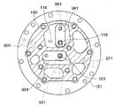
次に、図2〜図6を用いて、圧縮機1の詳細構成を説明する。圧縮機1は、1台のスクロール式圧縮機の圧縮部を2段に分けたスクロール式2段圧縮機構を備えた構成となっている。なお、図2の矢印DR1は、圧縮機1の上下方向を示している。 Next, the detailed configuration of the compressor 1 will be described with reference to FIGS. 2 to 6. The compressor 1 has a configuration provided with a scroll-type two-stage compression mechanism in which the compression unit of one scroll-type compressor is divided into two stages. The arrow DR1 in FIG. 2 indicates the vertical direction of the compressor 1.

図2に示すように、本実施形態の圧縮機1は、ハウジング30の下方部に配置されたスクロール式2段圧縮機構部40と、ハウジング30の上方部に配置され、スクロール式2段圧縮機構部40の駆動源である電動モータ20を備えている。なお、電動モータはハウジング30に設けられている端子と、不図示の配線で接続されている。 As shown in FIG. 2, the compressor 1 of the present embodiment has a scroll-type two-stage compression mechanism unit 40 arranged in a lower portion of the housing 30 and a scroll-type two-stage compression mechanism unit 40 arranged in an upper portion of the housing 30. It includes an electric motor 20 that is a drive source for the unit 40. The electric motor is connected to a terminal provided in the housing 30 by a wiring (not shown).

電動モータ20は、ロータ22とステータ23とを有し、ロータ22には駆動軸25が一体的に結合されている。駆動軸25の下端は、スクロール式2段圧縮機構40の可動スクロール11に接続されている。電動モータ20は、駆動軸25に接続された可動スクロール11を駆動する。 The electric motor 20 has a rotor 22 and a stator 23, and a drive shaft 25 is integrally coupled to the rotor 22. The lower end of the drive shaft 25 is connected to the movable scroll 11 of the scroll-type two-stage compression mechanism 40. The electric motor 20 drives the movable scroll 11 connected to the drive shaft 25.

スクロール式2段圧縮機構部40は、可動スクロール11および固定スクロール12を有している。可動スクロール11は、円板状の可動基板部111と、可動基板部111の一面から固定基板部121側へ向かって立設された渦巻き状の可動歯部112を有している。 The scroll-type two-stage compression mechanism unit 40 has a movable scroll 11 and a fixed scroll 12. The movable scroll 11 has a disk-shaped movable substrate portion 111 and a spiral movable tooth portion 112 erected from one surface of the movable substrate portion 111 toward the fixed substrate portion 121 side.

一方、固定スクロール12は、円板状の固定基板部121と、固定基板部121から可動基板部111側へ向かって立設された渦巻き状の固定歯部122を有している。固定基板部121は、ハウジング30に固定されている。なお、可動スクロール11は、可動歯部112が固定歯部122と噛み合うように配置されている。 On the other hand, the fixed scroll 12 has a disk-shaped fixed substrate portion 121 and a spiral-shaped fixed tooth portion 122 erected from the fixed substrate portion 121 toward the movable substrate portion 111. The fixed substrate portion 121 is fixed to the housing 30. The movable scroll 11 is arranged so that the movable tooth portion 112 meshes with the fixed tooth portion 122.

両基板部111、121は互いに上下方向に対向するように配置されている。電動モータ20の作動に伴って駆動軸25が回転すると、可動スクロール11は、駆動軸25の回転中心を公転中心として公転運動する。 Both substrate portions 111 and 121 are arranged so as to face each other in the vertical direction. When the drive shaft 25 rotates with the operation of the electric motor 20, the movable scroll 11 revolves around the center of rotation of the drive shaft 25 as the center of revolution.

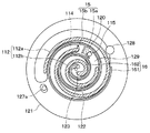
図4に示すように、固定基板部121の可動基板部111と対向する面に渦巻き状溝129が形成されており、この渦巻き状溝129の側壁が渦巻き状の歯部122を構成している。固定基板部121には、固定歯部122の間に形成された渦巻き状溝129を、所定箇所で仕切る仕切壁120が形成されている。具体的には、固定スクロール12には、渦巻き状溝129を、後述する高段側吸入口115と連通する高段側圧縮室15aと、後述する低段側吐出口114と連通する低段側圧縮室15bとに仕切る仕切壁120が形成されている。仕切壁120は、固定基板部121から可動基板部111側へ向かって立設されている。 As shown in FIG. 4, a spiral groove 129 is formed on the surface of the fixed substrate portion 121 facing the movable substrate portion 111, and the side wall of the spiral groove 129 constitutes the spiral tooth portion 122. .. The fixed substrate portion 121 is formed with a partition wall 120 that partitions the spiral groove 129 formed between the fixed tooth portions 122 at a predetermined position. Specifically, in the fixed scroll 12, the spiral groove 129 communicates with the high-stage side suction port 115 described later, the high-stage side compression chamber 15a, and the low-stage side discharge port 114 described later. A partition wall 120 that partitions the compression chamber 15b is formed. The partition wall 120 is erected from the fixed substrate portion 121 toward the movable substrate portion 111.

仕切壁120は、該仕切壁120より固定基板部121の径方向外側に位置する固定歯部122と、仕切壁120より固定基板部121の径方向内側に位置する固定歯部122と、を接続している。仕切壁120のうち低段側圧縮室15b側の側壁は湾曲した曲面となっており、仕切壁120のうち高段側圧縮室15a側の側壁は湾曲した曲面となっている。 The partition wall 120 connects the fixed tooth portion 122 located radially outside the fixed substrate portion 121 from the partition wall 120 and the fixed tooth portion 122 located radially inside the fixed substrate portion 121 from the partition wall 120. doing. The side wall of the partition wall 120 on the lower stage side compression chamber 15b side has a curved curved surface, and the side wall of the partition wall 120 on the higher stage side compression chamber 15a side has a curved curved surface.

仕切壁120により、固定歯部122の巻始め部側に高段側圧縮室15aが形成されるとともに固定歯部122の巻き終わり部側に低段側圧縮室15bが形成される。すなわち圧縮室15の中心側に高段側圧縮室15aが形成され、圧縮室15より径外方向に低段側圧縮室15bが形成される。 The partition wall 120 forms a high-stage compression chamber 15a on the winding start side of the fixed tooth portion 122 and a low-stage compression chamber 15b on the winding end side of the fixed tooth portion 122. That is, the high-stage side compression chamber 15a is formed on the center side of the compression chamber 15, and the low-stage side compression chamber 15b is formed in the outer diameter direction from the compression chamber 15.

図2〜図4に示すように、吐出プレート140は、固定スクロール12のうち下方側の面に対して、ガスケット130を介して取り付けられた板状の部材である。後に説明する中間圧室981および高段吐出室924は、いずれも、吐出プレート140と固定スクロール12との両方に跨るように形成されている。 As shown in FIGS. 2 to 4, the discharge plate 140 is a plate-shaped member attached to the lower surface of the fixed scroll 12 via the gasket 130. Both the intermediate pressure chamber 981 and the high-stage discharge chamber 924, which will be described later, are formed so as to straddle both the discharge plate 140 and the fixed scroll 12.

固定基板部121には、低段吸入流路901と、中間圧室981と、高段吐出室924と、高段吐出流路931と、中間インジェクション流路951と、オイル戻し流路971と、が形成されている。 The fixed substrate portion 121 includes a low-stage suction flow path 901, an intermediate pressure chamber 981, a high-stage discharge chamber 924, a high-stage discharge flow path 931, an intermediate injection flow path 951, and an oil return flow path 971. Is formed.

低段吸入流路901は、低段側圧縮室15bに冷媒を供給するための流路である。尚、低段吸入流路901には、室外熱交換器6に接続されるパイプが圧入されているのであるが、図3等では当該パイプの図示が省略されている。また、当該パイプはフランジ部を持ち、フランジ部によって、コンプレッサのハウジングハウジングの筒状部材31に接続され、コンプレッサが密閉される。ここで、当該パイプは、吸入ポートと同一である。低段吸入流路901に供給された冷媒は、貫通穴である冷媒吸入口128を通って低段側圧縮室15bに流入した後、この低段側圧縮室15bで圧縮される。 The low-stage suction flow path 901 is a flow path for supplying the refrigerant to the low-stage side compression chamber 15b. A pipe connected to the outdoor heat exchanger 6 is press-fitted into the low-stage suction flow path 901, but the pipe is not shown in FIG. 3 and the like. Further, the pipe has a flange portion, which is connected to the tubular member 31 of the housing housing of the compressor by the flange portion, and the compressor is sealed. Here, the pipe is the same as the suction port. The refrigerant supplied to the low-stage suction flow path 901 flows into the low-stage side compression chamber 15b through the refrigerant suction port 128 which is a through hole, and then is compressed in the low-stage side compression chamber 15b.

中間圧室981は、低段側圧縮室15bと高段側圧縮室15aとの間を繋ぐ流路として形成されている。低段側圧縮室15bにおいて圧縮された冷媒は、貫通穴である低段側吐出口114を通って中間圧室981に流入した後、貫通穴である高段側吸入口115を通って高段側圧縮室15aに流入する。その後、冷媒は高段側圧縮室15aにて圧縮される。ここで、低段側吐出口114と、高段側吐出口123の内、少なくとも一方には逆止弁が設けられていても良く、その逆止弁はリード弁と、弁ストッパから形成されることが多い。本実施例においては、吐出口を明確にするために、逆止弁を図示していない。 The intermediate pressure chamber 981 is formed as a flow path connecting the low-stage side compression chamber 15b and the high-stage side compression chamber 15a. The refrigerant compressed in the low-stage compression chamber 15b flows into the intermediate pressure chamber 981 through the low-stage side discharge port 114, which is a through hole, and then passes through the high-stage side suction port 115, which is a through hole. It flows into the side compression chamber 15a. After that, the refrigerant is compressed in the high-stage side compression chamber 15a. Here, a check valve may be provided at least one of the low-stage side discharge port 114 and the high-stage side discharge port 123, and the check valve is formed of a lead valve and a valve stopper. Often. In this embodiment, the check valve is not shown in order to clarify the discharge port.

また、中間圧室981には中間インジェクション流路951と連通しており、中間インジェクション流路951にはパイプが圧入されており、当該パイプはフランジ部を持ち、フランジ部によって、コンプレッサのハウジングハウジングの筒状部材31に接続され、コンプレッサが密閉される。ここで、当該パイプは、中間圧吸入と同一である。 Further, the intermediate pressure chamber 981 communicates with the intermediate injection flow path 951, and a pipe is press-fitted into the intermediate injection flow path 951. The pipe has a flange portion, and the flange portion of the compressor housing housing. It is connected to the tubular member 31 and the compressor is sealed. Here, the pipe is the same as the intermediate pressure suction.

高段吐出室924は、高段側圧縮室15aから排出された冷媒が流入する空間として、吐出プレート140と固定スクロール12との両方に跨るように形成された空間である。高段側圧縮室15aにおいて圧縮された冷媒は、貫通穴である吐出孔123を通って高段吐出室924に流入する。 The high-stage discharge chamber 924 is a space formed so as to straddle both the discharge plate 140 and the fixed scroll 12 as a space into which the refrigerant discharged from the high-stage side compression chamber 15a flows. The refrigerant compressed in the high-stage compression chamber 15a flows into the high-stage discharge chamber 924 through the discharge hole 123, which is a through hole.

高段吐出流路931は、高段吐出室924にある冷媒、すなわち高段側圧縮室15aにおいて圧縮された後の冷媒を、水−冷媒熱交換器2に導入する不図示の吐出配管に向けて排出するための流路である。 The high-stage discharge flow path 931 directs the refrigerant in the high-stage discharge chamber 924, that is, the refrigerant after being compressed in the high-stage side compression chamber 15a, toward a discharge pipe (not shown) for introducing the refrigerant into the water-refrigerant heat exchanger 2. It is a flow path for discharging.

オイル戻し流路971は、外部から圧縮機1に戻されるオイル(潤滑油)を受け入れて、これを固定スクロール12と可動スクロール11との間に供給するための流路である。ハウジング30の下方には、ハウジング30の底部に溜まったオイルを吸い上げるためのオイル吸い上げパイプ972が設けられている。低段吸入流路901からの冷媒の吸引が行われると、ハウジング30の底部に溜まったオイルがオイル吸い上げパイプ972およびオイル戻し孔127aを通って低段吸入流路901に導入される。その後、このオイルは各部の潤滑に供される。 The oil return flow path 971 is a flow path for receiving oil (lubricating oil) returned to the compressor 1 from the outside and supplying it between the fixed scroll 12 and the movable scroll 11. Below the housing 30, an oil suction pipe 972 for sucking up the oil accumulated at the bottom of the housing 30 is provided. When the refrigerant is sucked from the low-stage suction flow path 901, the oil collected at the bottom of the housing 30 is introduced into the low-stage suction flow path 901 through the oil suction pipe 972 and the oil return hole 127a. After that, this oil is used to lubricate each part.

図3〜図4に示すように、可動基板部111には、低段側吐出口114と高段側吸入口115とが形成されている。低段側吐出口114は、仕切壁120より低段側圧縮室15b側に形成されており、高段側吸入口115は、仕切壁120より高段側圧縮室15a側に形成されている。 As shown in FIGS. 3 to 4, the movable substrate portion 111 is formed with a low-stage side discharge port 114 and a high-stage side suction port 115. The low-stage side discharge port 114 is formed on the low-stage side compression chamber 15b side of the partition wall 120, and the high-stage side suction port 115 is formed on the high-stage side compression chamber 15a side of the partition wall 120.

両スクロール11、12の歯部112、122同士が噛み合って複数箇所で接触することによって、高段側圧縮室15aと低段側圧縮室15bとにそれぞれ複数個の圧縮室15が形成される。なお、図4では図示の都合上、仕切壁120と接する1つの高段側圧縮室15aと、仕切壁120と接する1つの低段側圧縮室15bに符号を付しており、他の圧縮室については符号を省略している。 When the tooth portions 112 and 122 of both scrolls 11 and 12 mesh with each other and come into contact with each other at a plurality of locations, a plurality of compression chambers 15 are formed in the high-stage side compression chamber 15a and the low-stage side compression chamber 15b, respectively. In FIG. 4, for convenience of illustration, one high-stage compression chamber 15a in contact with the partition wall 120 and one low-stage compression chamber 15b in contact with the partition wall 120 are designated by reference numerals, and the other compression chambers are designated. The code is omitted for.

図2〜図4に示すように、固定基板部121の中心部には、圧縮室15で圧縮された冷媒が吐出される吐出孔123が形成されている。固定基板部121内において吐出孔123の下方側には、吐出孔123と連通する高段吐出室924が形成されている。 As shown in FIGS. 2 to 4, a discharge hole 123 for discharging the refrigerant compressed in the compression chamber 15 is formed in the central portion of the fixed substrate portion 121. A high-stage discharge chamber 924 communicating with the discharge hole 123 is formed on the lower side of the discharge hole 123 in the fixed substrate portion 121.

高段吐出室924の冷媒は、冷媒吐出通路931に圧入された吐出配管に接続されるパイプ(図示せず)を通じてハウジング30外部へ吐出されるようになっている。また、当該パイプはフランジ部を持ち、フランジ部によって、圧縮機1のハウジング30の筒状部材31に接続され、コンプレッサが密閉される。ここで当該パイプは、吐出ポートと同一である。 The refrigerant in the high-stage discharge chamber 924 is discharged to the outside of the housing 30 through a pipe (not shown) connected to the discharge pipe press-fitted into the refrigerant discharge passage 931. Further, the pipe has a flange portion, and the flange portion connects the pipe to the tubular member 31 of the housing 30 of the compressor 1 to seal the compressor. Here, the pipe is the same as the discharge port.

図2、4に示すように、固定歯部122の先端部には、圧縮室15の気密性を確保するためのチップシール161が装着されている。また、可動歯部112の先端にもチップシール163が装着されている。チップシール161は、固定歯部122の渦巻き方向に沿って延び、かつ、図5に示すように、その断面は矩形状に形成されている。 As shown in FIGS. 2 and 4, a tip seal 161 for ensuring the airtightness of the compression chamber 15 is attached to the tip of the fixed tooth portion 122. A tip seal 163 is also attached to the tip of the movable tooth portion 112. The tip seal 161 extends along the spiral direction of the fixed tooth portion 122, and as shown in FIG. 5, its cross section is formed in a rectangular shape.

チップシール161は、固定歯部122の上面(可動基板部111側の面)に形成された凹部122b(詳細後述)に嵌入されている。また、チップシール163は、可動歯部112の下面(固定基板部121側の面)に形成された凹部に嵌入されている。また、仕切壁120の先端部120aには、圧縮室15の気密性を確保するためのチップシール162が装着されている。 The tip seal 161 is fitted in a recess 122b (described in detail later) formed on the upper surface (the surface on the movable substrate portion 111 side) of the fixed tooth portion 122. Further, the tip seal 163 is fitted in a recess formed on the lower surface (the surface on the fixed substrate portion 121 side) of the movable tooth portion 112. Further, a chip seal 162 for ensuring the airtightness of the compression chamber 15 is attached to the tip portion 120a of the partition wall 120.

チップシール162は、第1チップシールに相当し、チップシール161は、第2チップシールに相当する。両チップシール161、162は、ポリエーテル・エーテル・ケトン樹脂(PEEK)などの樹脂材料にて形成されている。両チップシール161、162は、それぞれ可動基板部111に密着して摺動する。これにより、圧縮室15の気密性を確保して、圧縮室15から冷媒が洩れることを防止する。 The chip seal 162 corresponds to the first chip seal, and the chip seal 161 corresponds to the second chip seal. Both chip seals 161 and 162 are made of a resin material such as polyetheretherketone resin (PEEK). Both chip seals 161 and 162 slide in close contact with the movable substrate portion 111, respectively. As a result, the airtightness of the compression chamber 15 is ensured, and the refrigerant is prevented from leaking from the compression chamber 15.

次に、チップシール161、162の構成について図4〜図6を用いて説明する。 Next, the configurations of the chip seals 161 and 162 will be described with reference to FIGS. 4 to 6.

固定スクロール12に形成された固定歯部122と、可動スクロール11の可動基板部111との間には、微少なクリアランスが設けられている。 A minute clearance is provided between the fixed tooth portion 122 formed on the fixed scroll 12 and the movable substrate portion 111 of the movable scroll 11.

このため、各圧縮室15の間に圧力差が生じたときに、固定スクロール12に形成された固定歯部122と、可動スクロール11の可動基板部111との間のクリアランスを通って冷媒が漏れてしまう。 Therefore, when a pressure difference is generated between the compression chambers 15, the refrigerant leaks through the clearance between the fixed tooth portion 122 formed on the fixed scroll 12 and the movable substrate portion 111 of the movable scroll 11. It ends up.

チップシール161は、固定スクロール12に形成された固定歯部122と、可動スクロール11の可動基板部111との間のクリアランスを通って冷媒が漏れるのを抑制する。 The tip seal 161 suppresses the leakage of the refrigerant through the clearance between the fixed tooth portion 122 formed on the fixed scroll 12 and the movable substrate portion 111 of the movable scroll 11.

チップシール161は、固定歯部122の先端部122aに配置されている。図5に示すように、固定歯部122の先端部122aには、チップシール161を嵌入するための凹部122bが形成されている。凹部122bは、シール収容溝である。チップシール161は、固定歯部122の先端部122aに形成された凹部122bに嵌入されている。 The tip seal 161 is arranged at the tip portion 122a of the fixed tooth portion 122. As shown in FIG. 5, a recess 122b for fitting the tip seal 161 is formed in the tip portion 122a of the fixed tooth portion 122. The recess 122b is a seal accommodating groove. The tip seal 161 is fitted in the recess 122b formed in the tip portion 122a of the fixed tooth portion 122.

チップシール161は、その断面形状が矩形であり、図5に示すように、可動基板部111に対向するシール外壁面161aと、収容溝底部内壁面122cに対向するシール底部外壁面161bと、を有している。チップシール161は、固定歯部122の先端部122aより突出している。 The chip seal 161 has a rectangular cross-sectional shape, and as shown in FIG. 5, the seal outer wall surface 161a facing the movable substrate portion 111 and the seal bottom outer wall surface 161b facing the accommodating groove bottom inner wall surface 122c are provided. Have. The tip seal 161 protrudes from the tip portion 122a of the fixed tooth portion 122.

チップシール162は、固定スクロール12の固定基板部121に形成された仕切壁120と、可動スクロール11の可動基板部111との間のクリアランスを通って高段側圧縮室15a側から低段側圧縮室15b側へ冷媒が漏れるのを抑制する。 The chip seal 162 is compressed from the high-stage side compression chamber 15a side to the low-stage side through a clearance between the partition wall 120 formed on the fixed substrate portion 121 of the fixed scroll 12 and the movable substrate portion 111 of the movable scroll 11. Suppresses the leakage of the refrigerant to the chamber 15b side.

チップシール162は、仕切壁120の先端部120aに配置されている。図6に示すように、仕切壁120の先端部120aには、チップシール162を嵌入するための凹部120bが形成されている。チップシール162は、仕切壁120の先端部120aに形成された凹部120bに嵌入されている。 The chip seal 162 is arranged at the tip end portion 120a of the partition wall 120. As shown in FIG. 6, a recess 120b for fitting the chip seal 162 is formed in the tip portion 120a of the partition wall 120. The tip seal 162 is fitted in a recess 120b formed in the tip portion 120a of the partition wall 120.

チップシール162は、仕切壁120より固定基板部121の径方向内側に位置するチップシール161と、仕切壁120より固定基板部121の径方向外側に位置するチップシール161との間に配置されている。 The chip seal 162 is arranged between the chip seal 161 located radially inside the fixed substrate portion 121 from the partition wall 120 and the chip seal 161 located radially outside the fixed substrate portion 121 from the partition wall 120. There is.

具体的には、チップシール162は、仕切壁120より固定基板部121の径方向内側に位置するチップシール161との間に隙間を設けて配置されるとともに、仕切壁120より固定基板部121の径方向外側に位置するチップシール161との間に隙間を設けて配置されている。 Specifically, the chip seal 162 is arranged so as to provide a gap between the chip seal 162 and the chip seal 161 located inside the fixed substrate portion 121 in the radial direction from the partition wall 120, and the chip seal 162 of the fixed substrate portion 121 from the partition wall 120. It is arranged with a gap between it and the chip seal 161 located on the outer side in the radial direction.

チップシール162は、その断面形状が矩形であり、図6に示すように、可動基板部111に対向するシール外壁面162aと、収容溝底部内壁面120cに対向するシール底部外壁面162bと、を有している。チップシール162は、仕切壁120の先端部120aよりも突出している。また、チップシール162の幅は、チップシール161と同一幅となっている。 The chip seal 162 has a rectangular cross-sectional shape, and as shown in FIG. 6, the seal outer wall surface 162a facing the movable substrate portion 111 and the seal bottom outer wall surface 162b facing the accommodating groove bottom inner wall surface 120c are provided. Have. The tip seal 162 protrudes from the tip portion 120a of the partition wall 120. Further, the width of the chip seal 162 is the same as that of the chip seal 161.

凹部120bと凹部122bとの間には、凹部120bと凹部122bとの間を隔てる隔壁部1205が設けられている。具体的には、隔壁部1205は、凹部120bと、凹部120bより固定基板部121の径方向外側に位置する凹部122bとの間と、凹部120bと、凹部120bより固定基板部121の径方向内側に位置する凹部122bとの間に設けられている。 Between the recess 120b and the recess 122b, a partition wall portion 1205 that separates the recess 120b and the recess 122b is provided. Specifically, the partition wall portion 1205 is provided between the recess 120b and the recess 122b located radially outside the fixed substrate portion 121 from the recess 120b, and radially inside the recess 120b and the fixed substrate portion 121 from the recess 120b. It is provided between the recess 122b and the recess 122b located in.

この隔壁部1205により、凹部122bから凹部120bを経由して、高段側から低段側へと加圧気体が漏れ高段側圧縮室15a側から低段側圧縮室15b側への冷媒漏れが抑制される。 Pressurized gas leaks from the high-stage side to the low-stage side by the partition wall portion 1205 from the recess 122b via the recess 120b, and the refrigerant leaks from the high-stage side compression chamber 15a side to the low-stage side compression chamber 15b side. It is suppressed.

ここで、チップシール161、162は突出せずに、チップシール底部外壁面161b、162bと収容溝底部内壁面122c、120c間に空間が設けられており、チップシール161、162の端部から圧縮室15b、15aで圧縮された高圧の冷媒が導入され、この冷媒によりチップシール161、162が可動基板部111側に押し付けられるよう構成してもよい。 Here, the chip seals 161 and 162 do not protrude, and a space is provided between the outer wall surfaces 161b and 162b at the bottom of the chip seal and the inner walls 122c and 120c at the bottom of the accommodating groove, and is compressed from the ends of the chip seals 161 and 162. A high-pressure refrigerant compressed in the chambers 15b and 15a may be introduced, and the chip seals 161 and 162 may be pressed against the movable substrate portion 111 by the refrigerant.

次に、作動を説明する。電動モータ20に電力が供給されて駆動軸25が回転すると、可動スクロール11が駆動軸25に対して公転運動(旋回)する。 Next, the operation will be described. When electric power is supplied to the electric motor 20 and the drive shaft 25 rotates, the movable scroll 11 revolves (turns) with respect to the drive shaft 25.

これにより、圧縮機1の吸入ポート30aから圧縮室15内に吸入される。そして、可動歯部112a、112bと固定歯部122との間に形成された三日月状の圧縮部が外周側から中心側へ容積を減少させながら移動する。 As a result, the air is sucked into the compression chamber 15 from the suction port 30a of the compressor 1. Then, the crescent-shaped compression portion formed between the movable tooth portions 112a and 112b and the fixed tooth portion 122 moves from the outer peripheral side to the central side while reducing the volume.

圧縮室15に供給された冷媒は、圧縮室15の容積の減少に伴って圧縮される。圧縮室15で圧縮された冷媒は、固定スクロール12の吐出孔123、吐出室124を通じて圧縮機1の冷媒吐出口30cから外部に吐出される。 The refrigerant supplied to the compression chamber 15 is compressed as the volume of the compression chamber 15 decreases. The refrigerant compressed in the compression chamber 15 is discharged to the outside from the refrigerant discharge port 30c of the compressor 1 through the discharge holes 123 and the discharge chamber 124 of the fixed scroll 12.

次に、可動スクロール11の旋回角度と可動歯部112a、112bと固定歯部122との間に形成される各部の圧力について説明する。 Next, the turning angle of the movable scroll 11 and the pressure of each portion formed between the movable tooth portions 112a and 112b and the fixed tooth portion 122 will be described.

図7は、可動スクロール11の旋回角度に対する固定歯部122および可動基板部111の状態を示した図である。図8は、図7に示した可動スクロールの回転角と圧縮室15内の各部の圧力の関係を表した図である。 FIG. 7 is a diagram showing a state of the fixed tooth portion 122 and the movable substrate portion 111 with respect to the turning angle of the movable scroll 11. FIG. 8 is a diagram showing the relationship between the rotation angle of the movable scroll shown in FIG. 7 and the pressure of each part in the compression chamber 15.

図7に示すように、可動スクロール11の旋回角度が、0度(360度)→45度(405度)→75度(435度)→90度(450度)→180度(540度)→270度(690度)→0度(360度)の順に変化すると、可動スクロール11の旋回角度の変化に応じて、可動歯部112a、112bと固定歯部122との間に形成される各部の容積も変化する。これに伴い、可動歯部112a、112bと固定歯部122との間に形成される各部の圧力X1、X2、X3、X4は、図8に示すように変化する。 As shown in FIG. 7, the turning angle of the movable scroll 11 is 0 degree (360 degrees) → 45 degrees (405 degrees) → 75 degrees (435 degrees) → 90 degrees (450 degrees) → 180 degrees (540 degrees) → When changing in the order of 270 degrees (690 degrees) → 0 degrees (360 degrees), each part formed between the movable tooth portions 112a and 112b and the fixed tooth portion 122 according to the change in the turning angle of the movable scroll 11. The volume also changes. Along with this, the pressures X1, X2, X3, and X4 of the respective portions formed between the movable tooth portions 112a and 112b and the fixed tooth portions 122 change as shown in FIG.

なお、冷媒吸入口128は、可動スクロール11の旋回角度と関係なく、常に開口している。また、図8に示すように、可動スクロール11の旋回角度が130度〜450度程度の間で低段側吐出口114は開口し、この低段側吐出口114から一定圧力X3の冷媒が吐出される。また、可動スクロール11の旋回角度が180度〜540度程度の間で吐出孔123は開口し、この吐出孔123から一定圧力X4の冷媒が吐出される。 The refrigerant suction port 128 is always open regardless of the turning angle of the movable scroll 11. Further, as shown in FIG. 8, the low-stage side discharge port 114 opens when the turning angle of the movable scroll 11 is about 130 degrees to 450 degrees, and the refrigerant having a constant pressure X3 is discharged from the low-stage side discharge port 114. Will be done. Further, the discharge hole 123 is opened when the turning angle of the movable scroll 11 is about 180 degrees to 540 degrees, and the refrigerant having a constant pressure X4 is discharged from the discharge hole 123.

本圧縮機1は、固定歯部122により形成された渦巻き状溝129にて構成される高段側圧縮室15aと低段側圧縮室15bとの間に仕切壁120が形成されており、この仕切壁120の先端部に仕切壁120と可動基板部111との間の隙間をシールするチップシール162を備えている。したがって、チップシール162により、高段側圧縮室15aから低段側圧縮室15bへの流体の漏れが抑制される。 In the compressor 1, a partition wall 120 is formed between the high-stage side compression chamber 15a and the low-stage side compression chamber 15b formed by the spiral groove 129 formed by the fixed tooth portions 122. The tip portion of the partition wall 120 is provided with a chip seal 162 that seals the gap between the partition wall 120 and the movable substrate portion 111. Therefore, the chip seal 162 suppresses the leakage of fluid from the high-stage compression chamber 15a to the low-stage compression chamber 15b.

ところで、高段側圧縮室15aから低段側圧縮室15bへの流体の漏れを抑制するためには、チップシール162とチップシール161を一体成形により構成するのが好ましい。しかし、チップシール162とチップシール161を射出成形により一体成形しようとした場合、チップシール162とチップシール161との接続部で素材が冷えてしまい、チップシール162とチップシール161がうまく接続されない可能性がある。 By the way, in order to suppress the leakage of fluid from the high-stage compression chamber 15a to the low-stage compression chamber 15b, it is preferable that the chip seal 162 and the chip seal 161 are integrally molded. However, when the chip seal 162 and the chip seal 161 are integrally molded by injection molding, the material may be cooled at the connection portion between the chip seal 162 and the chip seal 161 and the chip seal 162 and the chip seal 161 may not be connected well. There is sex.

そこで、チップシール162とチップシール161との接続部を加熱しながら射出成形により一体成形することも考えられるが、この場合、コストが高くなってしまうといった問題が生じる。 Therefore, it is conceivable that the connection portion between the chip seal 162 and the chip seal 161 is integrally molded by injection molding while heating, but in this case, there arises a problem that the cost becomes high.

これに対し、本実施形態の圧縮機1は、チップシール162とチップシール161は別体となっており、チップシール162とチップシール161との間に隙間が設けられている。したがって、チップシール162とチップシール161をそれぞれ良好に成形することができ、成形性に優れている。 On the other hand, in the compressor 1 of the present embodiment, the chip seal 162 and the chip seal 161 are separate bodies, and a gap is provided between the chip seal 162 and the chip seal 161. Therefore, the chip seal 162 and the chip seal 161 can be molded satisfactorily, respectively, and the moldability is excellent.

以上、説明したように、本圧縮機は、円板状の固定基板部121から立設された渦巻き状の固定歯部122を有する固定スクロール12と、円板状の可動基板部111の一面から立設されるとともに固定歯部122と噛み合う渦巻き状の可動歯部112を有する可動スクロール11と、を有し、可動スクロール11を固定スクロール12に対して旋回させることにより流体を多段圧縮して吐出する。 As described above, in this compressor, the fixed scroll 12 having the spiral fixed tooth portion 122 erected from the disc-shaped fixed substrate portion 121 and one surface of the disc-shaped movable substrate portion 111 It has a movable scroll 11 having a spiral movable tooth portion 112 that is erected and meshes with the fixed tooth portion 122, and the movable scroll 11 is swiveled with respect to the fixed scroll 12 to compress and discharge the fluid in multiple stages. To do.

さらに、固定基板部121から可動基板部111側に向かって立設されるとともに、固定歯部122により形成された渦巻き状溝の適所を、高段側圧縮室と低段側圧縮室とに仕切る仕切壁120を有している。また、仕切壁120の先端部120aに形成された凹部120bに配置され、仕切壁120と可動基板部111との間の隙間をシールするチップシール162を有している。また、渦巻き状の固定歯部122に沿うように固定歯部122の先端部122aに形成された凹部122bに配置され、固定歯部122と可動基板部111との間の隙間をシールするチップシール161を有している。そして、凹部120bと凹部122bとの間に、凹部120bと凹部122bとの間を隔てる隔壁部1205が設けられている。 Further, it is erected from the fixed substrate portion 121 toward the movable substrate portion 111 side, and the appropriate position of the spiral groove formed by the fixed tooth portion 122 is divided into a high-stage side compression chamber and a low-stage side compression chamber. It has a partition wall 120. Further, it has a chip seal 162 which is arranged in a recess 120b formed in the tip portion 120a of the partition wall 120 and seals a gap between the partition wall 120 and the movable substrate portion 111. Further, a tip seal is arranged in the recess 122b formed in the tip portion 122a of the fixed tooth portion 122 along the spiral fixed tooth portion 122, and seals the gap between the fixed tooth portion 122 and the movable substrate portion 111. It has 161. A partition wall portion 1205 is provided between the recess 120b and the recess 122b to separate the recess 120b and the recess 122b.

このような構成によれば、凹部120bと凹部122bとの間に、凹部120bと凹部122bとの間を隔てる隔壁部1205が設けられているので、凹部122bから凹部120bを経由して高段側圧縮室から低段側圧縮室へ流体が漏れるのが抑制されるので、圧縮機の小型化と効率向上を両立することができる。 According to such a configuration, since the partition wall portion 1205 that separates the recess 120b and the recess 122b is provided between the recess 120b and the recess 122b, the higher stage side is provided from the recess 122b via the recess 120b. Since fluid leakage from the compression chamber to the lower compression chamber is suppressed, it is possible to achieve both miniaturization and efficiency improvement of the compressor.

また、仕切壁120の先端部120aには、チップシール162が嵌入される凹部122bが形成されており、チップシール162は、凹部122bに嵌入されている。したがって、チップシール162を容易に凹部122bに取り付けることができる。 Further, the tip portion 120a of the partition wall 120 is formed with a recess 122b into which the tip seal 162 is fitted, and the tip seal 162 is fitted in the recess 122b. Therefore, the tip seal 162 can be easily attached to the recess 122b.

また、渦巻き状の固定歯部122に沿うように固定歯部122の先端部122aに配置され、固定歯部122と可動基板部111との間の隙間をシールするチップシール161を備えている。 Further, a tip seal 161 is provided which is arranged at the tip portion 122a of the fixed tooth portion 122 along the spiral fixed tooth portion 122 and seals the gap between the fixed tooth portion 122 and the movable substrate portion 111.

したがって、チップシール162により固定歯部122と可動基板部111との間の隙間がシールされ、固定歯部122と可動基板部111との間の隙間から漏れる冷媒を抑制することができる。 Therefore, the gap between the fixed tooth portion 122 and the movable substrate portion 111 is sealed by the chip seal 162, and the refrigerant leaking from the gap between the fixed tooth portion 122 and the movable substrate portion 111 can be suppressed.

また、チップシール162の幅は、チップシール161と同一幅となっている。したがって、チップシール162を収容する溝とチップシール161を収容する溝の溝加工を同一の刃具で行うことが可能であり、チップシール162とチップシール161の幅を異ならせる場合と比較して作業性を向上することができ、製造コストを低減することも可能である。 Further, the width of the chip seal 162 is the same as that of the chip seal 161. Therefore, it is possible to perform grooving of the groove accommodating the chip seal 162 and the groove accommodating the chip seal 161 with the same cutting tool, and the work is compared with the case where the widths of the chip seal 162 and the chip seal 161 are different. It is possible to improve the property and reduce the manufacturing cost.

また、チップシール162は、仕切壁120の先端部120aより突出している。このように、チップシール162を、仕切壁120の先端部120aより突出して配置することができる。 Further, the chip seal 162 projects from the tip portion 120a of the partition wall 120. In this way, the chip seal 162 can be arranged so as to project from the tip portion 120a of the partition wall 120.

(第2実施形態)
本発明の第2実施形態に係る圧縮機1について図5、6、9を用いて説明する。上記第1実施形態では、チップシール162の幅が、チップシール161と同一幅となっている。これに対し、本実施形態のチップシール162の幅がチップシール161と異なっている。また、仕切壁120は、低段側圧縮室と接する低段側面1201と、高段側圧縮室と接する高段側面1202を有している。そして、チップシール162は、チップシール162より固定基板部121の径方向内側に位置するチップシール161、チップシール162より固定基板部121の径方向外側に位置するチップシール161、低段側面1201および高段側面1202にそれぞれ沿った形状を成している。
(Second Embodiment)
The compressor 1 according to the second embodiment of the present invention will be described with reference to FIGS. 5, 6 and 9. In the first embodiment, the width of the chip seal 162 is the same as that of the chip seal 161. On the other hand, the width of the chip seal 162 of the present embodiment is different from that of the chip seal 161. Further, the partition wall 120 has a low-stage side surface 1201 in contact with the low-stage side compression chamber and a high-stage side surface 1202 in contact with the high-stage side compression chamber. The chip seal 162 includes a chip seal 161 located radially inside the fixed substrate portion 121 from the chip seal 162, a chip seal 161 located radially outside the fixed substrate portion 121 from the chip seal 162, and a low step side surface 1201. It has a shape along each of the high-level side surfaces 1202.

また、チップシール162は、チップシール161と別体として構成されている。チップシール162は、このチップシール162より固定基板部121の径方向外側に位置するチップシール161との間に隙間が形成されるとともに、チップシール162より固定基板部121の径方向内側に位置するチップシール161との間に隙間が形成されるよう配置されている。 Further, the chip seal 162 is configured as a separate body from the chip seal 161. The chip seal 162 has a gap formed between the chip seal 162 and the chip seal 161 located on the radial outside of the fixed substrate portion 121, and is located on the radial inside of the fixed substrate portion 121 from the chip seal 162. It is arranged so that a gap is formed between the chip seal 161 and the chip seal 161.

図5、6に示したように、チップシール161は、凹部120bに配置され、チップシール162は、凹部122bに配置されている。凹部120bと凹部122bとの間には、凹部120bと凹部122bとの間を隔てる隔壁部1205が設けられている。具体的には、隔壁部1205は、凹部120bと、凹部120bより固定基板部121の径方向外側に位置する凹部122bとの間および凹部120bと、凹部120bより固定基板部121の径方向内側に位置する凹部122bとの間に設けられている。 As shown in FIGS. 5 and 6, the chip seal 161 is arranged in the recess 120b, and the chip seal 162 is arranged in the recess 122b. Between the recess 120b and the recess 122b, a partition wall portion 1205 that separates the recess 120b and the recess 122b is provided. Specifically, the partition wall portion 1205 is provided between the recess 120b and the recess 122b located radially outside the fixed substrate portion 121 from the recess 120b, and inside the recess 120b in the radial direction of the fixed substrate portion 121. It is provided between the recess 122b and the recess 122b.

凹部120bは、該凹部120bより固定基板部121の径方向内側に位置する凹部122bおよび凹部120bより固定基板部121の径方向外側に位置する凹部122bに沿った形状を成している。 The recess 120b has a shape along a recess 122b located radially inside the fixed substrate portion 121 from the recess 120b and a recess 122b located radially outside the fixed substrate portion 121 from the recess 120b.

したがって、上記第1実施形態の圧縮機1と比較して、チップシール161とチップシール162との間に形成される各隙間の長さが長くなっているので、高段側圧縮室15aから、この凹み部122bと120bの間の隔壁部1205上を経由して、低段側圧縮室15bへ漏れる冷媒漏れが抑制され、チップシール162による冷媒漏れの抑制効果を向上することができる。 Therefore, as compared with the compressor 1 of the first embodiment, the length of each gap formed between the chip seal 161 and the chip seal 162 is longer, so that the high-stage side compression chamber 15a can be used. Refrigerant leakage that leaks to the lower compression chamber 15b via the partition wall portion 1205 between the recessed portions 122b and 120b is suppressed, and the effect of suppressing refrigerant leakage by the chip seal 162 can be improved.

さらに、凹部120bは、仕切壁120の低段側圧縮室側の側壁に沿った形状を成している。これにより、仕切壁120の先端部120aと可動基板部111との間のデッドボリュームが低減でき、当該デッドボリュームを経由する低段側圧縮機構内の漏れを抑制できる。 Further, the recess 120b has a shape along the side wall of the partition wall 120 on the lower stage side compression chamber side. As a result, the dead volume between the tip portion 120a of the partition wall 120 and the movable substrate portion 111 can be reduced, and leakage in the low-stage compression mechanism via the dead volume can be suppressed.

また、本実施形態の圧縮機1は、チップシール162とチップシール161は別体として構成されており、チップシール162とチップシール161との間に隙間が設けられている。したがって、チップシール162とチップシール161をそれぞれ良好に成形することができ、成形性に優れている。 Further, in the compressor 1 of the present embodiment, the chip seal 162 and the chip seal 161 are configured as separate bodies, and a gap is provided between the chip seal 162 and the chip seal 161. Therefore, the chip seal 162 and the chip seal 161 can be molded satisfactorily, respectively, and the moldability is excellent.

また、チップシール161およびチップシール162が枝分かれしていないため、安定して成型することができる。したがって、歩留まりを向上することができ、低コストで各チップシール161、162を成型することができる。 Further, since the chip seal 161 and the chip seal 162 are not branched, stable molding can be performed. Therefore, the yield can be improved, and the chip seals 161 and 162 can be molded at low cost.

(第3実施形態)
本発明の第3実施形態に係る圧縮機1について図10〜図11を用いて説明する。本実施形態のチップシール162は、仕切壁120より固定基板部121の径方向外側に位置するチップシール161と接続されており、仕切壁120より固定基板部121の径方向内側に位置するチップシール161との間に隙間が形成されている。
(Third Embodiment)
The compressor 1 according to the third embodiment of the present invention will be described with reference to FIGS. 10 to 11. The chip seal 162 of the present embodiment is connected to the chip seal 161 located radially outside the fixed substrate portion 121 from the partition wall 120, and is located radially inside the fixed substrate portion 121 from the partition wall 120. A gap is formed between the 161 and the 161.

チップシール162は、仕切壁120の先端部120aに形成された凹部120bに配置され、仕切壁120と可動基板部111との間の隙間をシールする。チップシール161は、渦巻き状の固定歯部122に沿うように固定歯部122の先端部122aに形成された凹部122bに配置され、固定歯部122と可動基板部111との間の隙間をシールする。また、隔壁部1205は、凹部120bと凹部122bとの間に設けられている。 The chip seal 162 is arranged in the recess 120b formed in the tip portion 120a of the partition wall 120, and seals the gap between the partition wall 120 and the movable substrate portion 111. The tip seal 161 is arranged in the recess 122b formed in the tip portion 122a of the fixed tooth portion 122 along the spiral fixed tooth portion 122, and seals the gap between the fixed tooth portion 122 and the movable substrate portion 111. To do. Further, the partition wall portion 1205 is provided between the recess 120b and the recess 122b.

隔壁部1205は、凹部120bと、凹部120bより固定基板部121の径方向内側に位置する凹部122bとの間に設けられている。また、凹部120bは、凹部120bより固定基板部121の径方向外側に位置する凹部122bと連通している。 The partition wall portion 1205 is provided between the recess 120b and the recess 122b located radially inside the fixed substrate portion 121 from the recess 120b. Further, the recess 120b communicates with the recess 122b located radially outside the fixed substrate portion 121 from the recess 120b.

本実施形態では、上記第1実施形態と共通の構成から奏される同様の効果を上記第1実施形態と同様に得ることができる。 In the present embodiment, the same effect obtained from the same configuration as that of the first embodiment can be obtained in the same manner as that of the first embodiment.

図11は、図7に示した可動スクロールの回転角が45度(405度)の場合における仕切壁120により仕切られた低段側圧縮室15bの拡大図である。 FIG. 11 is an enlarged view of the low-stage compression chamber 15b partitioned by the partition wall 120 when the rotation angle of the movable scroll shown in FIG. 7 is 45 degrees (405 degrees).

圧縮機1では、固定基板部121の中心に近い圧縮室15ほど高圧になる。すなわち、低段側圧縮室15bのうち、可動歯部112bよりも外側の圧力X1は、可動歯部112bよりも内側の圧力X3よりも低くなる。つまり、低段側圧縮室15bのうち、可動歯部112bよりも外側の圧力X1と高段側圧縮室15aとの差圧の方が、可動歯部112bよりも内側の圧力X3と高段側圧縮室15aとの差圧よりも大きくなる。 In the compressor 1, the pressure becomes higher in the compression chamber 15 closer to the center of the fixed substrate portion 121. That is, in the lower compression chamber 15b, the pressure X1 outside the movable tooth portion 112b is lower than the pressure X3 inside the movable tooth portion 112b. That is, in the low-stage compression chamber 15b, the pressure difference between the pressure X1 outside the movable tooth portion 112b and the high-stage side compression chamber 15a is the pressure X3 inside the movable tooth portion 112b and the high-stage side. It becomes larger than the differential pressure with the compression chamber 15a.

したがって、凹部120bと、この凹部120bより固定基板部121の径方向外側に位置する凹部122bを接続した方が、凹部120bと、この凹部120bより固定基板部121の径方向内側に位置する凹部122bを接続するよりも、冷媒の漏れを抑制する効果を大きくすることができる。 Therefore, connecting the recess 120b and the recess 122b located radially outside the fixed substrate portion 121 from the recess 120b connects the recess 120b and the recess 122b located radially inside the fixed substrate portion 121 from the recess 120b. The effect of suppressing the leakage of the refrigerant can be made larger than that of connecting the above.

すなわち、チップシール162と、このチップシール162より固定基板部121の径方向外側に位置するチップシール161との接続部を接続した方が、チップシール162と、このチップシール162より固定基板部121の径方向内側に位置するチップシール161との接続部を接続するよりも、冷媒の漏れを抑制する効果を大きくすることができる。 That is, it is better to connect the connection portion between the chip seal 162 and the chip seal 161 located radially outside the fixed substrate portion 121 from the chip seal 162, so that the chip seal 162 and the fixed substrate portion 121 from the chip seal 162 are connected. It is possible to increase the effect of suppressing the leakage of the refrigerant as compared with connecting the connection portion with the chip seal 161 located on the inner side in the radial direction of the above.

本実施形態のチップシール162は、仕切壁120より固定基板部121の径方向外側に位置するチップシール161と接続されているので、冷媒漏れの抑制効果を向上することができる。 Since the chip seal 162 of the present embodiment is connected to the chip seal 161 located radially outside the fixed substrate portion 121 from the partition wall 120, the effect of suppressing refrigerant leakage can be improved.

また、仕切壁120より固定基板部121の径方向外側に位置するチップシール161と、仕切壁120より固定基板部121の径方向内側に位置するチップシール161の両側にチップシール162を接続した場合、チップシール製造時に、チップシール161とチップシール162の各接続部がうまく接続されない可能性がある。 Further, when the chip seal 161 located radially outside the fixed substrate portion 121 from the partition wall 120 and the chip seal 162 located on both sides of the chip seal 161 located radially inside the fixed substrate portion 121 from the partition wall 120 are connected. At the time of manufacturing the chip seal, there is a possibility that the connection portions of the chip seal 161 and the chip seal 162 are not connected well.

しかし、本実施形態のチップシール162は、仕切壁120より固定基板部121の径方向内側に位置するチップシール161との間に隙間が形成されている。したがって、仕切壁120より固定基板部121の径方向外側に位置するチップシール161と、仕切壁120より固定基板部121の径方向内側に位置するチップシール161の両側にチップシール162を接続した場合と比較して成形性に優れている。 However, the chip seal 162 of the present embodiment has a gap formed between the partition wall 120 and the chip seal 161 located radially inside the fixed substrate portion 121. Therefore, when the chip seal 161 located radially outside the fixed substrate portion 121 from the partition wall 120 and the chip seal 162 located on both sides of the chip seal 161 located radially inside the fixed substrate portion 121 from the partition wall 120 are connected. It is excellent in moldability as compared with.

また、仕切壁120より固定基板部121の径方向外側に位置するチップシール161と、仕切壁120より固定基板部121の径方向内側に位置するチップシール161の両側にチップシール162を接続した場合、チップシール161、162への冷媒が浸透、熱の影響により、チップシール161、162が伸び縮みし、狙ったシール効果を得られないが、本実施形態においては、これらの問題は発生しない。 Further, when the chip seal 161 located radially outside the fixed substrate portion 121 from the partition wall 120 and the chip seal 162 located on both sides of the chip seal 161 located radially inside the fixed substrate portion 121 from the partition wall 120 are connected. , The refrigerant permeates the chip seals 161 and 162, and the chip seals 161 and 162 expand and contract due to the influence of heat, and the desired sealing effect cannot be obtained. However, in the present embodiment, these problems do not occur.

(第4実施形態)
本発明の第4実施形態に係る圧縮機について図12〜図14を用いて説明する。本実施形態の圧縮機1では、固定歯部122の先端部121aには、チップシール161が嵌入される凹部122bが形成されており、チップシール161は、凹部122bに嵌入されている。また、固定歯部122の先端部121aに形成された凹部122bと、仕切壁120の先端部120aに形成された凹部122bは連続している。また、チップシール161と凹部122bとの間およびチップシール162と凹部122bとの間には、それぞれ隙間161c、162cが設けられている。また、チップシール162は、該チップシール162より固定基板部121の径方向内側に位置するチップシール161と接続されており、チップシール162より固定基板部121の径方向外側に位置するチップシール161との間に隙間が形成されている。
(Fourth Embodiment)
The compressor according to the fourth embodiment of the present invention will be described with reference to FIGS. 12 to 14. In the compressor 1 of the present embodiment, the tip portion 121a of the fixed tooth portion 122 is formed with a recess 122b into which the tip seal 161 is fitted, and the tip seal 161 is fitted in the recess 122b. Further, the recess 122b formed in the tip portion 121a of the fixed tooth portion 122 and the recess 122b formed in the tip portion 120a of the partition wall 120 are continuous. Further, gaps 161c and 162c are provided between the tip seal 161 and the recess 122b and between the tip seal 162 and the recess 122b, respectively. Further, the chip seal 162 is connected to the chip seal 161 located radially inside the fixed substrate portion 121 from the chip seal 162, and the chip seal 161 located radially outside the fixed substrate portion 121 from the chip seal 162. A gap is formed between the and.

チップシール162は、仕切壁120の先端部120aに形成された凹部120bに配置され、仕切壁120と可動基板部111との間の隙間をシールする。チップシール161は、渦巻き状の固定歯部122に沿うように固定歯部122の先端部122aに形成された凹部122bに配置され、固定歯部122と可動基板部111との間の隙間をシールする。また、隔壁部1205は、凹部120bと凹部122bとの間に設けられている。 The chip seal 162 is arranged in the recess 120b formed in the tip portion 120a of the partition wall 120, and seals the gap between the partition wall 120 and the movable substrate portion 111. The tip seal 161 is arranged in the recess 122b formed in the tip portion 122a of the fixed tooth portion 122 along the spiral fixed tooth portion 122, and seals the gap between the fixed tooth portion 122 and the movable substrate portion 111. To do. Further, the partition wall portion 1205 is provided between the recess 120b and the recess 122b.

隔壁部1205は、凹部120bと、凹部120bより固定基板部121の径方向外側に位置する凹部122bとの間に設けられている。また、凹部120bは、凹部120bより固定基板部121の径方向外側に位置する凹部122bと連通している。 The partition wall portion 1205 is provided between the recess 120b and the recess 122b located radially outside the fixed substrate portion 121 from the recess 120b. Further, the recess 120b communicates with the recess 122b located radially outside the fixed substrate portion 121 from the recess 120b.

本実施形態では、上記第1実施形態と共通の構成から奏される同様の効果を上記第1実施形態と同様に得ることができる。 In the present embodiment, the same effect obtained from the same configuration as that of the first embodiment can be obtained in the same manner as that of the first embodiment.

また、可動スクロール11が公転運動を開始すると、圧縮室15に供給された冷媒は、圧縮室15の容積の減少に伴って圧縮される。このとき、冷媒が高圧となるチップシール161の中心側の端部からチップシール161と凹部122bとの間の隙間161cに冷媒が入り込む。 Further, when the movable scroll 11 starts to revolve, the refrigerant supplied to the compression chamber 15 is compressed as the volume of the compression chamber 15 decreases. At this time, the refrigerant enters the gap 161c between the chip seal 161 and the recess 122b from the central end of the chip seal 161 in which the refrigerant has a high pressure.

そして、チップシール161と凹部122bとの間の隙間161cに入り込んだ冷媒は、チップシール161とチップシール162との接続部に向かって流れた後、さらに、チップシール161とチップシール162との接続部より先にあるシール底部外壁面162bと収容溝底部内壁面120cとの間に形成される隙間161cと、チップシール162と凹部122bとの間の隙間162cに分岐して流れる。 Then, the refrigerant that has entered the gap 161c between the chip seal 161 and the recess 122b flows toward the connection portion between the chip seal 161 and the chip seal 162, and then further connects the chip seal 161 and the chip seal 162. The gap 161c formed between the outer wall surface 162b of the bottom of the seal and the inner wall surface 120c of the bottom of the accommodating groove, which is ahead of the portion, and the gap 162c between the tip seal 162 and the recess 122b branch and flow.

この際、チップシール161と凹部122bとの間の隙間161cを流れる冷媒の圧力により、チップシール161を可動基板部111側に押し付ける力が作用する。 At this time, a force that presses the chip seal 161 toward the movable substrate portion 111 acts due to the pressure of the refrigerant flowing through the gap 161c between the chip seal 161 and the recess 122b.

さらに、チップシール162と凹部122bとの間の隙間162cを流れる冷媒の圧力により、チップシール162を可動基板部111側に押し付る力が作用する。 Further, the pressure of the refrigerant flowing through the gap 162c between the chip seal 162 and the recess 122b exerts a force that presses the chip seal 162 toward the movable substrate portion 111.

このように、隙間161c、162cを流れる冷媒によりチップシール161、162を可動基板部111側に押し付る力が作用するので、シール性をより向上することができる。 As described above, since the force that presses the chip seals 161 and 162 against the movable substrate portion 111 side by the refrigerant flowing through the gaps 161c and 162c acts, the sealing property can be further improved.

ところで、チップシール162と、仕切壁120より固定基板部121の径方向外側に位置するチップシール161との間に接続部を設け、チップシール162と、仕切壁120より固定基板部121の径方向内側に位置するチップシール161との間に隙間を設けることもできる。 By the way, a connection portion is provided between the chip seal 162 and the chip seal 161 located radially outside the fixed substrate portion 121 from the partition wall 120, and the chip seal 162 and the fixed substrate portion 121 in the radial direction from the partition wall 120 are provided. A gap may be provided between the chip seal 161 and the chip seal 161 located inside.

しかし、この場合、チップシール161とチップシール162との接続部が、固定基板部121の中心から比較的離れた位置に形成されることになるため、チップシール162が可動基板部111側に押し付けられる力が弱く、シール性が低下してしまう。 However, in this case, since the connection portion between the chip seal 161 and the chip seal 162 is formed at a position relatively distant from the center of the fixed substrate portion 121, the chip seal 162 is pressed against the movable substrate portion 111 side. The force to be applied is weak, and the sealing property is deteriorated.

これに対し、本実施形態のチップシール162は、仕切壁120より固定基板部121の径方向内側に位置するチップシール161との間に接続部が設けられているので、チップシール162が可動基板部111側に押し付けられる力をより強くすることができ、より高いシール性を確保することが可能である。 On the other hand, in the chip seal 162 of the present embodiment, since the connection portion is provided between the partition wall 120 and the chip seal 161 located inside the fixed substrate portion 121 in the radial direction, the chip seal 162 is a movable substrate. The force pressed against the portion 111 can be strengthened, and higher sealing performance can be ensured.

また、本実施形態のチップシール162は、仕切壁120より固定基板部121の径方向外側に位置するチップシール161との間に隙間が形成されている。したがって、仕切壁120より固定基板部121の径方向外側に位置するチップシール161と、仕切壁120より固定基板部121の径方向内側に位置するチップシール161の両側にチップシール162を接続した場合と比較して成形性に優れている。 Further, the chip seal 162 of the present embodiment has a gap formed between the partition wall 120 and the chip seal 161 located on the radial outer side of the fixed substrate portion 121. Therefore, when the chip seal 161 located radially outside the fixed substrate portion 121 from the partition wall 120 and the chip seal 162 located on both sides of the chip seal 161 located radially inside the fixed substrate portion 121 from the partition wall 120 are connected. It is excellent in moldability as compared with.

(第5実施形態)
本発明の第5実施形態に係る圧縮機について図15を用いて説明する。本実施形態の圧縮機1では、チップシール161は、仕切壁120の先端部120aの固定基板部121の径方向外側に位置する固定歯部122で2つに分断されている。
(Fifth Embodiment)
The compressor according to the fifth embodiment of the present invention will be described with reference to FIG. In the compressor 1 of the present embodiment, the chip seal 161 is divided into two by a fixed tooth portion 122 located on the radial outer side of the fixed substrate portion 121 of the tip portion 120a of the partition wall 120.

また、チップシール162は、チップシール161の一方の分断端部に接続された第1分断チップシール1611と、チップシールの他方の分断端部に接続された第2分断チップシール1612と、を有している。 Further, the chip seal 162 includes a first divided chip seal 1611 connected to one divided end portion of the chip seal 161 and a second divided chip seal 1612 connected to the other divided end portion of the chip seal. have.

チップシール162は、仕切壁120の先端部120aの固定基板部121の径方向外側に位置する固定歯部122で2つに分断されている。 The chip seal 162 is divided into two by a fixed tooth portion 122 located on the radial outer side of the fixed substrate portion 121 of the tip portion 120a of the partition wall 120.

凹部120bは、チップシール162が配置される凹部の一方の分断端部に接続された第1分断凹部120baと、チップシール162が配置される凹部122bの他方の分断端部に接続された第2分断凹部120bbと、を有している。 The recess 120b was connected to a first dividing recess 120ba connected to one dividing end of the recess in which the chip seal 162 is arranged and to the other dividing end of the recess 122b in which the tip seal 162 is arranged. It has a second dividing recess 120bb and the like.

隔壁部1205は、第1分断凹部120baと、この第1分断凹部120baより固定基板部121の径方向内側に位置する凹部122bとの間および第2分断凹部120bbと、この第2分断凹部120bより固定基板部121の径方向内側に位置する凹部122bとの間にそれぞれ設けられている。 The partition wall portion 1205 is formed between the first dividing recess 120ba and the recess 122b located radially inside the fixed substrate portion 121 from the first dividing recess 120ba, the second dividing recess 120bb, and the second dividing recess 120b. It is provided between the fixed substrate portion 121 and the recess 122b located inside in the radial direction.

第1分断チップシール1611およびチップシール1621は、低段側圧縮室15bを囲むように配置され、第2分断チップシール1612およびチップシール1622は、高段側圧縮室15aを囲むように配置されている。 The first divided chip seal 1611 and the chip seal 1621 are arranged so as to surround the lower stage side compression chamber 15b, and the second divided chip seal 1612 and the chip seal 1622 are arranged so as to surround the higher stage side compression chamber 15a. There is.

このように、チップシール161の一方の分断端部に接続された第1分断チップシール1611と、チップシールの他方の分断端部に接続された第2分断チップシール1612の二段で、高段側圧縮室15aから低段側圧縮室15bへの冷媒漏れを抑制することが可能である。 As described above, the two stages of the first divided chip seal 1611 connected to one of the divided ends of the chip seal 161 and the second divided chip seal 1612 connected to the other divided end of the chip seal 161 It is possible to suppress the leakage of the refrigerant from the high-stage side compression chamber 15a to the low-stage side compression chamber 15b.

また、第1分断チップシール1611とチップシール1621を連続して成形することができ、さらに、第2分断チップシール1612とチップシール1622を連続し、かつ、分岐のない形状で成形することができるので、成形性に優れている。 Further, the first divided chip seal 1611 and the chip seal 1621 can be continuously molded, and further, the second divided chip seal 1612 and the chip seal 1622 can be continuously formed and formed in a shape without branching. Therefore, it is excellent in moldability.

(第6実施形態)
本発明の第6実施形態に係る圧縮機について図16を用いて説明する。本実施形態の圧縮機1では、チップシール161は、仕切壁120の先端部120aの固定基板部121の径方向外側に位置する固定歯部122で2つに分断されている。また、チップシール162は、チップシール161の一方の分断端部に接続された第1分断チップシール1611と、チップシールの他方の分断端部に接続された第2分断チップシール1612と、を有している。
(Sixth Embodiment)
The compressor according to the sixth embodiment of the present invention will be described with reference to FIG. In the compressor 1 of the present embodiment, the chip seal 161 is divided into two by a fixed tooth portion 122 located on the radial outer side of the fixed substrate portion 121 of the tip portion 120a of the partition wall 120. Further, the chip seal 162 includes a first divided chip seal 1611 connected to one divided end portion of the chip seal 161 and a second divided chip seal 1612 connected to the other divided end portion of the chip seal. have.

(第7実施形態)
本発明の第7実施形態に係る圧縮機について図17を用いて説明する。本実施形態の圧縮機1では、チップシール161は、仕切壁120の先端部120aの固定基板部121の径方向外側に位置する固定歯部122で2つに分断されている。また、チップシール162は、チップシール161の一方の分断端部に接続されている。具体的には、チップシール162は、該チップシール162より固定基板部121の径方向外側に位置するチップシール161と接続されている。
(7th Embodiment)
The compressor according to the seventh embodiment of the present invention will be described with reference to FIG. In the compressor 1 of the present embodiment, the chip seal 161 is divided into two by a fixed tooth portion 122 located on the radial outer side of the fixed substrate portion 121 of the tip portion 120a of the partition wall 120. Further, the chip seal 162 is connected to one of the divided ends of the chip seal 161. Specifically, the chip seal 162 is connected to the chip seal 161 located on the radial outer side of the fixed substrate portion 121 from the chip seal 162.

チップシール162は、仕切壁120の先端部120aの固定基板部121の径方向外側に位置する固定歯部122で2つに分断されている。 The chip seal 162 is divided into two by a fixed tooth portion 122 located on the radial outer side of the fixed substrate portion 121 of the tip portion 120a of the partition wall 120.

凹部120bは、チップシール162が配置される凹部の一方の分断端部に接続されている。 The recess 120b is connected to one of the split ends of the recess in which the tip seal 162 is arranged.

隔壁部1205は、凹部120bと、この凹部120bより固定基板部121の径方向内側に位置する凹部122bとの間に設けられている。 The partition wall portion 1205 is provided between the recess 120b and the recess 122b located radially inside the fixed substrate portion 121 from the recess 120b.

凹部120bの幅は、チップシール162が配置される凹部122bと同じになっている。 The width of the recess 120b is the same as that of the recess 122b in which the chip seal 162 is arranged.

このように、チップシール161は、仕切壁120の先端部120aの固定基板部121の径方向外側に位置する固定歯部122で2つに分断され、チップシール162は、チップシール161の一方の分断端部に接続されるよう構成することもできる。 As described above, the chip seal 161 is divided into two by the fixed tooth portion 122 located on the radial outer side of the fixed substrate portion 121 of the tip portion 120a of the partition wall 120, and the chip seal 162 is one of the chip seals 161. It can also be configured to be connected to the split end.

(第8実施形態)
本発明の第8実施形態に係る圧縮機について図18を用いて説明する。本実施形態の圧縮機1では、チップシール161は、仕切壁120の先端部120aの固定基板部121の径方向外側に位置する固定歯部122で2つに分断されている。また、チップシール162は、チップシール161の一方の分断端部に接続されている。
(8th Embodiment)
The compressor according to the eighth embodiment of the present invention will be described with reference to FIG. In the compressor 1 of the present embodiment, the chip seal 161 is divided into two by a fixed tooth portion 122 located on the radial outer side of the fixed substrate portion 121 of the tip portion 120a of the partition wall 120. Further, the chip seal 162 is connected to one of the divided ends of the chip seal 161.

凹部120bは、チップシール162に接続されたチップシール161の一方の分断端部が配置される凹部122bに接続されている。 The recess 120b is connected to a recess 122b in which one of the split ends of the chip seal 161 connected to the chip seal 162 is arranged.

隔壁部1205は、凹部120bと、この凹部120bよりより固定基板部121の径方向内側に位置する凹部122bとの間に設けられている。 The partition wall portion 1205 is provided between the recess 120b and the recess 122b located radially inside the fixed substrate portion 121 from the recess 120b.

凹部120bの幅は、チップシール162が配置される凹部122bと同じになっている。 The width of the recess 120b is the same as that of the recess 122b in which the chip seal 162 is arranged.

また、凹部120bは、仕切壁120の低段側圧縮室側の側壁に沿った形状を成している。 Further, the recess 120b has a shape along the side wall of the partition wall 120 on the side of the compression chamber on the lower stage side.

上記したように、チップシール161は、仕切壁120の先端部120aの固定基板部121の径方向外側に位置する固定歯部122で2つに分断され、チップシール162は、チップシール161の一方の分断端部に接続されるよう構成することもできる。 As described above, the chip seal 161 is divided into two by the fixed tooth portion 122 located radially outside the fixed substrate portion 121 of the tip portion 120a of the partition wall 120, and the chip seal 162 is one of the chip seals 161. It can also be configured to be connected to the fragmented end of the.

(第9実施形態)
本発明の第9実施形態に係る圧縮機について図19を用いて説明する。本実施形態の圧縮機1は、凹部120bの幅が、凹部122bの幅の半分以上となっている。また、凹部120bの幅が、凹部122bに近づくにつれて徐々に広くなっている。
(9th Embodiment)
The compressor according to the ninth embodiment of the present invention will be described with reference to FIG. In the compressor 1 of the present embodiment, the width of the recess 120b is more than half the width of the recess 122b. Further, the width of the recess 120b gradually increases as it approaches the recess 122b.

チップシール162は、仕切壁120の先端部120aに形成された凹部120bの形状に合うように成型され、凹部120bに配置される。また、チップシール161は、渦巻き状の固定歯部122に沿うように固定歯部122の先端部122aに形成された凹部122bに配置される。 The chip seal 162 is molded so as to match the shape of the recess 120b formed in the tip 120a of the partition wall 120, and is arranged in the recess 120b. Further, the tip seal 161 is arranged in the recess 122b formed in the tip portion 122a of the fixed tooth portion 122 so as to be along the spiral fixed tooth portion 122.

凹部120bに配置されるチップシール162は、凹部122bに配置されるチップシール161のおよそ0.5倍以上の圧力がかかることから、チップシール162は、チップシール161の半分以上の幅が必要である。したがって、凹部120bの幅を、凹部122bの幅の半分以上とすることで、流体の漏れを抑制することができる。 Since the chip seal 162 arranged in the recess 120b applies a pressure of about 0.5 times or more that of the chip seal 161 arranged in the recess 122b, the chip seal 162 needs to be at least half the width of the chip seal 161. is there. Therefore, by setting the width of the recess 120b to more than half the width of the recess 122b, fluid leakage can be suppressed.

なお、チップシール162の幅を広げることで、仕切壁120上のデッドボリュームを削減できるため、チップシール162の幅は、チップシール161の幅よりも広くするのが望ましい。 Since the dead volume on the partition wall 120 can be reduced by increasing the width of the chip seal 162, it is desirable that the width of the chip seal 162 is wider than the width of the chip seal 161.

また、隔壁部1205は、凹部120bと、凹部120bより固定基板部121の径方向外側に位置する凹部122bとの間に設けられている。また、凹部120bは、凹部120bより固定基板部121の径方向内側に位置する凹部122bと連通している。 Further, the partition wall portion 1205 is provided between the recess 120b and the recess 122b located radially outside the fixed substrate portion 121 from the recess 120b. Further, the recess 120b communicates with the recess 122b located inside the fixed substrate portion 121 in the radial direction from the recess 120b.

また、凹部120bは、凹部122bに近付くにつれて幅が徐々に広くなっているので、凹部120bおよび凹部122bに嵌入される各チップシール161、162の成型性を容易にできるため、低コストを実現できる。 Further, since the width of the recess 120b gradually increases as it approaches the recess 122b, the moldability of the chip seals 161 and 162 fitted into the recess 120b and the recess 122b can be easily formed, so that low cost can be realized. ..

(第10実施形態)
本発明の第10実施形態に係る圧縮機について図20を用いて説明する。上記第9実施形態では、隔壁部1205は、凹部120bと、凹部120bより固定基板部121の径方向外側に位置する凹部122bとの間に設けられている。また、凹部120bは、凹部120bより固定基板部121の径方向内側に位置する凹部122bと連通している。これに対し、本実施形態では、隔壁部1205は、凹部120bと、凹部120bより固定基板部121の径方向内側に位置する凹部122bとの間に設けられている。また、凹部120bは、凹部120bより固定基板部121の径方向外側に位置する凹部122bと連通している。
(10th Embodiment)
The compressor according to the tenth embodiment of the present invention will be described with reference to FIG. In the ninth embodiment, the partition wall portion 1205 is provided between the recess 120b and the recess 122b located radially outside the fixed substrate portion 121 from the recess 120b. Further, the recess 120b communicates with the recess 122b located inside the fixed substrate portion 121 in the radial direction from the recess 120b. On the other hand, in the present embodiment, the partition wall portion 1205 is provided between the recess 120b and the recess 122b located radially inside the fixed substrate portion 121 from the recess 120b. Further, the recess 120b communicates with the recess 122b located radially outside the fixed substrate portion 121 from the recess 120b.

なお、上記第9実施形態と同様に、凹部120bの幅が、凹部122bに近づくにつれて徐々に広くなっている。 As in the ninth embodiment, the width of the recess 120b gradually increases as it approaches the recess 122b.

このように、凹部120bの幅が、凹部122bに近づくにつれて徐々に広くなるよう構成することで、嵌入されるチップシール161、162の成型を容易に行うことができるので、形成のためのコストを低減することが可能である。 In this way, by configuring the recess 120b so that the width gradually increases as it approaches the recess 122b, it is possible to easily mold the chip seals 161 and 162 to be fitted, so that the cost for forming the recess 120b can be reduced. It can be reduced.

(第11実施形態)
本発明の第11実施形態に係る圧縮機について図21を用いて説明する。本実施形態での圧縮機は、上記第10実施形態の圧縮機と比較して、チップシール162が、仕切壁120の先端部120aの固定基板部121の径方向外側に位置する固定歯部122で2つに分断されており、凹部120bは、チップシール162が配置される凹部の一方の分断端部に接続されている点が異なる。
(11th Embodiment)
The compressor according to the eleventh embodiment of the present invention will be described with reference to FIG. In the compressor of the present embodiment, as compared with the compressor of the tenth embodiment, the chip seal 162 has a fixed tooth portion 122 located on the radial outer side of the fixed substrate portion 121 of the tip portion 120a of the partition wall 120. The recess 120b is different in that it is divided into two by the above, and the recess 120b is connected to one of the split ends of the recess in which the chip seal 162 is arranged.

なお、隔壁部1205は、凹部120bと、凹部120bより固定基板部121の径方向内側に位置する凹部122bとの間に設けられている。 The partition wall portion 1205 is provided between the recess 120b and the recess 122b located radially inside the fixed substrate portion 121 from the recess 120b.

(第12実施形態)
本発明の第12実施形態に係る圧縮機について図22を用いて説明する。本実施形態の圧縮機1は、上記第11実施形態の圧縮機と比較して、凹部120bの幅が、凹部122bの半分となっている部位を有している点が異なる。
(12th Embodiment)
The compressor according to the twelfth embodiment of the present invention will be described with reference to FIG. The compressor 1 of the present embodiment is different from the compressor of the eleventh embodiment in that the width of the recess 120b is half that of the recess 122b.

このように、凹部120bの幅が、凹部122bの半分となっている部位を有しており、凹部120bの幅が、凹部122bに近づくにつれて徐々に広くなっている。なお、チップシール162は凹部120bの形状に合わせて成型され、凹部120bに配置される。 As described above, the recess 120b has a portion where the width of the recess 120b is half that of the recess 122b, and the width of the recess 120b gradually increases as it approaches the recess 122b. The tip seal 162 is molded according to the shape of the recess 120b and is arranged in the recess 120b.

このように、凹部120bの幅が、凹部122bに近づくにつれて徐々に広くなるよう構成することで、嵌入されるチップシール161、162の成型を容易に行うことができるので、形成のためのコストを低減することが可能である。 In this way, by configuring the recess 120b so that the width gradually increases as it approaches the recess 122b, it is possible to easily mold the chip seals 161 and 162 to be fitted, so that the cost for forming the recess 120b can be reduced. It can be reduced.

(第13実施形態)
本発明の第13実施形態に係る圧縮機について図23を用いて説明する。本実施形態の圧縮機は、上記第2実施形態の圧縮機と比較して、凹部120bと、凹部120bより固定基板部121の径方向内側に位置する凹部122bとの間に隔壁部1205が設けられていない点が異なる。
(13th Embodiment)
The compressor according to the thirteenth embodiment of the present invention will be described with reference to FIG. Compared to the compressor of the second embodiment, the compressor of the present embodiment is provided with the partition wall portion 1205 between the recess 120b and the recess 122b located radially inside the fixed substrate portion 121 from the recess 120b. The difference is that it is not.

このように、凹部120bと、凹部120bより固定基板部121の径方向外側に位置する凹部122bとの間に隔壁部1205を配置し、凹部120bと、凹部120bより固定基板部121の径方向内側に位置する凹部122bとの間に隔壁部1205を配置しないように構成することもでできる。 In this way, the partition wall portion 1205 is arranged between the recess 120b and the recess 122b located radially outside the fixed substrate portion 121 from the recess 120b, and the recess 120b and the recess 120b are radially inside the fixed substrate portion 121. It is also possible to configure the partition wall portion 1205 so as not to be arranged between the partition wall portion 1205 and the recess 122b located in.

(第14実施形態)
本発明の第14実施形態に係る圧縮機について図24を用いて説明する。本実施形態の圧縮機は、凹部120bが、該凹部120bより固定基板部121の径方向内側に位置する凹部122bに沿うように形成された部位120bcと、凹部120bより固定基板部121の径方向外側に位置する凹部122bに沿うように形成された部位120bdと、部位120bcと部位120bdとの間を結ぶ直線状の部位120beとを有している。
(14th Embodiment)
The compressor according to the 14th embodiment of the present invention will be described with reference to FIG. 24. In the compressor of the present embodiment, the recess 120b is formed so as to be along the recess 122b located inside the fixed substrate portion 121 in the radial direction from the recess 120b, and the recess 120b in the radial direction of the fixed substrate portion 121. It has a portion 120b formed along the concave portion 122b located on the outer side, and a linear portion 120be connecting the portion 120bc and the portion 120bd.

チップシール161は、各部位120bc、120bd、120beの形状にに合わせて成型されている。 The tip seal 161 is molded according to the shape of each part 120bc, 120bd, 120be.

このように、凹部120bを形成し、この凹部120bの形状に合わて成型されたチップシール161を凹部120bに配置することもできる。 In this way, the recess 120b can be formed, and the chip seal 161 molded to match the shape of the recess 120b can be arranged in the recess 120b.

(第15実施形態)
本発明の第15実施形態に係る圧縮機について図25〜27を用いて説明する。上記第8実施形の凹部120bは、仕切壁120の低段側圧縮室側の側壁に沿った曲線形状を成している。これに対し、図25〜27に示すように、凹部120bを仕切壁120の低段側圧縮室側の側壁に沿った形状とすることもできる。具体的には、図25に示すように仕切壁120の低段側圧縮室側の側壁から所定長、離れた位置に凹部120bを形成することもできる。また、図26に示すように、仕切壁120の低段側圧縮室側の側壁に沿うように2本の曲線を組み合わせて凹部120bを形成することもできる。また、図27に示すように、仕切壁120の低段側圧縮室側の側壁に沿うように3本の曲線を組み合わせて凹部120bを形成することもできる。なお、チップシール162は各凹部120bに配置される。
(15th Embodiment)
The compressor according to the fifteenth embodiment of the present invention will be described with reference to FIGS. 25 to 27. The recess 120b of the eighth embodiment has a curved shape along the side wall of the partition wall 120 on the side of the compression chamber on the lower stage side. On the other hand, as shown in FIGS. 25 to 27, the recess 120b may be shaped along the side wall of the partition wall 120 on the lower compression chamber side. Specifically, as shown in FIG. 25, the recess 120b can be formed at a position separated from the side wall on the lower stage side compression chamber side of the partition wall 120 by a predetermined length. Further, as shown in FIG. 26, the recess 120b can be formed by combining two curves along the side wall of the partition wall 120 on the lower stage side compression chamber side. Further, as shown in FIG. 27, the recess 120b can be formed by combining three curves along the side wall of the partition wall 120 on the lower stage side compression chamber side. The chip seal 162 is arranged in each recess 120b.

(第16実施形態)
本発明の第16実施形態に係る圧縮機について図28を用いて説明する。上記第1実施形態の圧縮機1は、凹部120bの低段側圧縮室側の側壁と仕切壁120の低段側圧縮室側の側壁との距離aと、凹部120bの高段側圧縮室側の側壁と仕切壁120の高段側圧縮室側の側壁との距離bについて規定されていない。
(16th Embodiment)
The compressor according to the 16th embodiment of the present invention will be described with reference to FIG. 28. In the compressor 1 of the first embodiment, the distance a between the side wall of the recess 120b on the low-stage side compression chamber side and the side wall of the partition wall 120 on the low-stage side compression chamber side and the side wall of the recess 120b on the high-stage side compression chamber side The distance b between the side wall of the partition wall 120 and the side wall of the partition wall 120 on the high-stage side compression chamber side is not specified.

本実施形態の凹部120bは、凹部120bの低段側圧縮室側の側壁と仕切壁120の低段側圧縮室側の側壁との最短距離aが、凹部120bの高段側圧縮室側の側壁と仕切壁の高段側圧縮室側の側壁との最短距離bよりも小さくなるよう形成されている。そして、チップシール162は凹部120bに配置される。 In the recess 120b of the present embodiment, the shortest distance a between the side wall of the recess 120b on the low-stage side compression chamber side and the side wall of the partition wall 120 on the low-stage side compression chamber side is the side wall of the recess 120b on the high-stage side compression chamber side. It is formed so as to be smaller than the shortest distance b between the partition wall and the side wall on the high stage side compression chamber side. Then, the chip seal 162 is arranged in the recess 120b.

これによれば、仕切り壁120の先端部120aと可動基板部111との間のデッドスペースを少なくすることができ、圧縮機1の効率を向上することができる。 According to this, the dead space between the tip portion 120a of the partition wall 120 and the movable substrate portion 111 can be reduced, and the efficiency of the compressor 1 can be improved.

(第17実施形態)
本発明の第17実施形態に係る圧縮機について図29を用いて説明する。本実施形態の圧縮機1は、チップシール161が途中で分断されている。具体的には、連続する凹部120bに、途中で分断されたチップシール161が配置されている。
(17th Embodiment)
The compressor according to the 17th embodiment of the present invention will be described with reference to FIG. 29. In the compressor 1 of the present embodiment, the chip seal 161 is divided in the middle. Specifically, the chip seal 161 divided in the middle is arranged in the continuous recess 120b.

このように、連続する凹部120bに、途中で分断されたチップシール161を配置することもできる。 In this way, the chip seal 161 divided in the middle can be arranged in the continuous recesses 120b.

(第18実施形態)
本発明の第18実施形態に係る圧縮機について図30を用いて説明する。本実施形態の圧縮機1は、チップシール161が途中で分断されている。具体的には、途中で分断された凹部120bに、それぞれチップシール161が配置されている。
(18th Embodiment)
The compressor according to the eighteenth embodiment of the present invention will be described with reference to FIG. In the compressor 1 of the present embodiment, the chip seal 161 is divided in the middle. Specifically, the chip seal 161 is arranged in each of the recesses 120b divided in the middle.

このように、途中で分断された凹部120bに、それぞれチップシール161を配置することもできる。 In this way, the chip seal 161 can be arranged in each of the recesses 120b divided in the middle.

(第19実施形態)
本発明の第19実施形態に係る圧縮機について図31を用いて説明する。本実施形態の圧縮機1は、本実施形態の圧縮機1は、固定基板部121であって、低段側圧縮室15bに、圧縮機1の中間圧吸入ポート30bと連通する中間圧吸入孔116が形成されている。このように、圧縮機1の中間圧吸入ポート30bと連通する中間圧吸入孔116を基板部121に形成することもできる。
(19th Embodiment)
The compressor according to the 19th embodiment of the present invention will be described with reference to FIG. In the compressor 1 of the present embodiment, the compressor 1 of the present embodiment is a fixed substrate portion 121, and an intermediate pressure suction hole communicating with the intermediate pressure suction port 30b of the compressor 1 in the lower stage side compression chamber 15b. 116 is formed. In this way, the intermediate pressure suction hole 116 communicating with the intermediate pressure suction port 30b of the compressor 1 can be formed in the substrate portion 121.

(第20実施形態)
本発明の第20実施形態に係る圧縮機について図32〜34を用いて説明する。本実施形態の圧縮機1を適用したヒートポンプサイクル100は、上記第1実施形態の圧縮機1を適用したヒートポンプサイクル100と比較して、さらに、気液分離器4と第2膨張弁5の間に、第3膨張弁7および気液分離器8を備えた点が異なる。
(20th Embodiment)
The compressor according to the twentieth embodiment of the present invention will be described with reference to FIGS. 32 to 34. The heat pump cycle 100 to which the compressor 1 of the present embodiment is applied is further compared with the heat pump cycle 100 to which the compressor 1 of the first embodiment is applied, and is further between the gas-liquid separator 4 and the second expansion valve 5. The difference is that a third expansion valve 7 and a gas-liquid separator 8 are provided.

第3膨張弁7は、気液分離器4の液相冷媒流出口から流出した中間圧液相冷媒を低圧冷媒となるまで減圧させる低段側減圧部であって、その基本的構成は第1膨張弁3と同様である。 The third expansion valve 7 is a low-stage side pressure reducing portion that reduces the pressure of the intermediate pressure liquid phase refrigerant flowing out from the liquid phase refrigerant outlet of the gas-liquid separator 4 until it becomes a low pressure refrigerant, and its basic configuration is the first. This is the same as the expansion valve 3.

気液分離器8は、第3膨張弁7にて減圧された中間圧冷媒の気液を分離する気液分離部である。気液分離器8にて分離された中間圧気相冷媒は、圧縮機1の中間圧吸入ポート30dを介して圧縮機1の圧縮室15にて圧縮過程の途中の冷媒に注入される。 The gas-liquid separator 8 is a gas-liquid separator that separates the gas-liquid of the intermediate pressure refrigerant decompressed by the third expansion valve 7. The intermediate pressure gas phase refrigerant separated by the gas-liquid separator 8 is injected into the refrigerant in the middle of the compression process in the compression chamber 15 of the compressor 1 via the intermediate pressure suction port 30d of the compressor 1.

第2膨張弁5は、気液分離器8の液相冷媒流出口から流出した中間圧液相冷媒を低圧冷媒となるまで減圧させる低段側減圧部であって、その基本的構成は第1膨張弁3と同様である。このようなヒートポンプサイクル100に本圧縮機1を適用することもできる。 The second expansion valve 5 is a low-stage side decompression unit that depressurizes the intermediate-pressure liquid-phase refrigerant flowing out from the liquid-phase refrigerant outlet of the gas-liquid separator 8 until it becomes a low-pressure refrigerant, and its basic configuration is the first. This is the same as the expansion valve 3. The compressor 1 can also be applied to such a heat pump cycle 100.

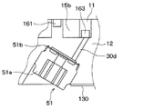
図33に示すように、本実施形態の固定基板部121には、さらに、固定基板部121に、低段インジェクション流路941と、低段インジェクション室942と、が形成されている。また、低段インジェクション室942には、低段側圧縮室15bに流入した冷媒が中間圧吸入ポート30d側に逆流するのを防止する逆止弁51が設けられている。 As shown in FIG. 33, the fixed substrate portion 121 of the present embodiment is further formed with a low-stage injection flow path 941 and a low-stage injection chamber 942 in the fixed substrate portion 121. Further, the low-stage injection chamber 942 is provided with a check valve 51 for preventing the refrigerant flowing into the low-stage compression chamber 15b from flowing back to the intermediate pressure suction port 30d side.

低段インジェクション流路941は、低段側圧縮機構4にインジェクションされる冷媒が通る流路である。なお、低段インジェクション流路941には、パイプが圧入されているのであるが、図33等では当該パイプの図示が省略されている。また、当該パイプはフランジ部を有し、ハウジングの筒状部材31に接続されることによって、コンプレッサが密閉される。低段インジェクション流路941を通った冷媒は低段インジェクション室942に流入する。 The low-stage injection flow path 941 is a flow path through which the refrigerant injected into the low-stage compression mechanism 4 passes. A pipe is press-fitted into the low-stage injection flow path 941, but the pipe is not shown in FIG. 33 and the like. Further, the pipe has a flange portion and is connected to the tubular member 31 of the housing to seal the compressor. The refrigerant that has passed through the low-stage injection flow path 941 flows into the low-stage injection chamber 942.

低段インジェクション室942は、低段インジェクション流路941を通った冷媒が流入する空間として、吐出プレート140と固定スクロール12との両方に跨るように形成された空間である。低段インジェクション室942に流入した冷媒は、貫通穴である低段インジェクションポート943を通って低段側圧縮室15bにインジェクションされる。 The low-stage injection chamber 942 is a space formed so as to straddle both the discharge plate 140 and the fixed scroll 12 as a space through which the refrigerant flows through the low-stage injection flow path 941. The refrigerant that has flowed into the low-stage injection chamber 942 is injected into the low-stage compression chamber 15b through the low-stage injection port 943, which is a through hole.

中間インジェクション流路951は、中間圧室981にインジェクションされる冷媒が通る流路である。なお、中間インジェクション流路951には、パイプが圧入されているのであるが、図33等では当該パイプの図示が省略されている。当該パイプはフランジ部を持ち、フランジ部によって、コンプレッサのハウジング30の筒状部材31に接続され、コンプレッサが密閉される。中間インジェクション流路951を通った冷媒は中間圧室981にインジェクションされる。 The intermediate injection flow path 951 is a flow path through which the refrigerant injected into the intermediate pressure chamber 981 passes. Although a pipe is press-fitted into the intermediate injection flow path 951, the illustration of the pipe is omitted in FIG. 33 and the like. The pipe has a flange portion, which is connected to the tubular member 31 of the compressor housing 30 by the flange portion, and the compressor is sealed. The refrigerant that has passed through the intermediate injection flow path 951 is injected into the intermediate pressure chamber 981.

図34に示すように、逆止弁51は、弁座51aおよびリード弁51bを有している。低段側圧縮室15bに流入した冷媒が中間圧吸入ポート30d側に逆流しようとすると、リード弁51bが中間圧吸入ポート30dと連通する通路を塞いで低段側圧縮室15bに流入した冷媒が中間圧吸入ポート30d側に逆流するのを防止する。 As shown in FIG. 34, the check valve 51 has a valve seat 51a and a lead valve 51b. When the refrigerant flowing into the low-stage compression chamber 15b tries to flow back to the intermediate pressure suction port 30d, the lead valve 51b blocks the passage communicating with the intermediate pressure suction port 30d, and the refrigerant flowing into the low-stage compression chamber 15b Prevents backflow to the intermediate pressure suction port 30d side.

(第21実施形態)
本発明の第21実施形態に係る圧縮機について図35を用いて説明する。本実施形態の圧縮機1を適用したヒートポンプサイクル100は、上記第1実施形態の圧縮機1を適用したヒートポンプサイクル100と比較して、気液分離器4および第2膨張弁5を備えていない点と、圧縮機1に中間圧吸入ポート30bが設けられていない点が異なる。
(21st Embodiment)
The compressor according to the 21st embodiment of the present invention will be described with reference to FIG. 35. The heat pump cycle 100 to which the compressor 1 of the present embodiment is applied does not include the gas-liquid separator 4 and the second expansion valve 5 as compared with the heat pump cycle 100 to which the compressor 1 of the first embodiment is applied. The difference is that the compressor 1 is not provided with the intermediate pressure suction port 30b.

このようなヒートポンプサイクル100に本圧縮機1を適用することもできる。なお、このようなヒートポンプサイクル100に、本圧縮機1を適用する際には、図3に示した低段側吐出口114と高段側吸入口115との間を直接接続すればよい。 The compressor 1 can also be applied to such a heat pump cycle 100. When the compressor 1 is applied to such a heat pump cycle 100, the low-stage side discharge port 114 and the high-stage side suction port 115 shown in FIG. 3 may be directly connected.

(他の実施形態)
(1)上記各実施形態では、固定歯部122の先端部122aに凹部122bを形成し、この凹部122bにチップシール161を嵌入するとともに、仕切壁120の先端部120aに凹部120bを形成し、この凹部120bにチップシール162を嵌入したが、このような取り付け手法に限定されるものではない。
(Other embodiments)
(1) In each of the above embodiments, the recess 122b is formed in the tip 122a of the fixed tooth portion 122, the tip seal 161 is fitted in the recess 122b, and the recess 120b is formed in the tip 120a of the partition wall 120. Although the chip seal 162 is fitted into the recess 120b, the present invention is not limited to such an attachment method.

(2)上記各実施形態では、固定基板部121の仕切壁120に凹部を設けた、凹部にチップシールを嵌入したが、可動基板部111であって、固定基板121の仕切壁120に接する部位に、凹部と凹部に嵌入するチップシールを設けるようにしてもよい。 (2) In each of the above embodiments, the partition wall 120 of the fixed substrate portion 121 is provided with a recess, and the chip seal is fitted in the recess. However, the movable substrate portion 111 is a portion in contact with the partition wall 120 of the fixed substrate portion 121. May be provided with a recess and a tip seal that fits into the recess.

(3)上記各実施形態では、可動歯部112の先端部にチップシールを配置したが、必ずしも可動歯部112の先端部にチップシールを配置する必要はない。 (3) In each of the above embodiments, the tip seal is arranged at the tip of the movable tooth portion 112, but it is not always necessary to arrange the tip seal at the tip of the movable tooth portion 112.

(4)上記各実施形態では、固定歯部122により形成された渦巻き状溝129の外側に低段側圧縮室15bが配置され、渦巻き状溝129の内側に高段側圧縮室15aが配置されるよう構成した。これに対し、固定歯部122により形成された渦巻き状溝129の内側に低段側圧縮室15bが配置され、渦巻き状溝129の外側に高段側圧縮室15aが配置されるよう構成してもよい。 (4) In each of the above embodiments, the low-stage compression chamber 15b is arranged outside the spiral groove 129 formed by the fixed tooth portions 122, and the high-stage compression chamber 15a is arranged inside the spiral groove 129. It was configured to. On the other hand, the low-stage compression chamber 15b is arranged inside the spiral groove 129 formed by the fixed tooth portion 122, and the high-stage compression chamber 15a is arranged outside the spiral groove 129. May be good.

(5)上記実施形態には、チップシール162の断面形状が矩形となるよう構成されたものが含まれるが、矩形以外の形状とすることもできる。 (5) The above-described embodiment includes a chip seal 162 having a rectangular cross-sectional shape, but the tip seal 162 may have a shape other than the rectangular shape.

(6)低段側圧縮室15bを構成する低段側圧縮機と、高段側圧縮室15aを構成する高段側圧縮を別々に構成してもよい。 (6) The low-stage compressor constituting the low-stage compression chamber 15b and the high-stage compression constituting the high-stage compression chamber 15a may be separately configured.

(7)上記各実施形態では、固定スクロール12に形成された固定歯部122の巻き数は、1.5巻きよりも多くなっているが、固定スクロール12に形成された固定歯部122の巻き数を、1.5巻きよりも少なくすることもできる。固定スクロール12に形成された固定歯部122の巻き数が、1.5巻きよりも少ない場合、シールチップシール162と可動基板部111との隙間およびチップシール161と可動基板部111との隙間を通って流体が高段圧縮室から低段圧縮室を通って低段側吸入室へ漏れる可能性がある。このため、固定スクロール12に形成された固定歯部122の巻き数は、1.5巻きよりも少ない圧縮機において、凹部120bと凹部122bとの間に、凹部120bと凹部122bとの間を隔てる隔壁部1205を設けることで、流体が高段圧縮室15aから低段圧縮室15bを通って低段側吸入室へ漏れるのを抑制することができる。 (7) In each of the above embodiments, the number of turns of the fixed tooth portion 122 formed on the fixed scroll 12 is larger than 1.5 turns, but the number of turns of the fixed tooth portion 122 formed on the fixed scroll 12 is increased. The number can be less than 1.5 rolls. When the number of turns of the fixed tooth portion 122 formed on the fixed scroll 12 is less than 1.5 turns, the gap between the seal tip seal 162 and the movable substrate portion 111 and the gap between the chip seal 161 and the movable substrate portion 111 are formed. Fluid may leak from the high-stage compression chamber through the low-stage compression chamber to the low-stage suction chamber. Therefore, in a compressor in which the number of turns of the fixed tooth portion 122 formed on the fixed scroll 12 is less than 1.5 turns, the recess 120b and the recess 122b are separated from each other. By providing the partition wall portion 1205, it is possible to prevent the fluid from leaking from the high-stage compression chamber 15a through the low-stage compression chamber 15b to the low-stage suction chamber.

なお、本発明は上記した実施形態に限定されるものではなく、特許請求の範囲に記載した範囲内において適宜変更が可能である。また、上記各実施形態は、互いに無関係なものではなく、組み合わせが明らかに不可な場合を除き、適宜組み合わせが可能である。また、上記各実施形態において、実施形態を構成する要素は、特に必須であると明示した場合および原理的に明らかに必須であると考えられる場合等を除き、必ずしも必須のものではないことは言うまでもない。また、上記各実施形態において、実施形態の構成要素の個数、数値、量、範囲等の数値が言及されている場合、特に必須であると明示した場合および原理的に明らかに特定の数に限定される場合等を除き、その特定の数に限定されるものではない。また、上記各実施形態において、構成要素等の材質、形状、位置関係等に言及するときは、特に明示した場合および原理的に特定の材質、形状、位置関係等に限定される場合等を除き、その材質、形状、位置関係等に限定されるものではない。 The present invention is not limited to the above-described embodiment, and can be appropriately modified within the scope of the claims. Further, the above-described embodiments are not unrelated to each other, and can be appropriately combined unless the combination is clearly impossible. Further, in each of the above embodiments, it goes without saying that the elements constituting the embodiment are not necessarily essential except when it is clearly stated that they are essential and when they are clearly considered to be essential in principle. No. Further, in each of the above embodiments, when numerical values such as the number, numerical values, amounts, and ranges of the constituent elements of the embodiment are mentioned, when it is clearly stated that they are particularly essential, and in principle, they are clearly limited to a specific number. It is not limited to the specific number except when it is done. Further, in each of the above embodiments, when referring to the material, shape, positional relationship, etc. of the constituent elements, etc., except when specifically specified or when the material, shape, positional relationship, etc. are limited in principle. , The material, shape, positional relationship, etc. are not limited.

(まとめ)
上記各実施形態の一部または全部で示された第1の観点によれば、圧縮機は、円板状の固定基板部から立設された渦巻き状の固定歯部を有する固定スクロールと、円板状の可動基板部の一面から立設されるとともに固定歯部と噛み合う渦巻き状の可動歯部を有する可動スクロールと、を有している。そして、可動スクロールを固定スクロールに対して旋回させることにより流体を多段圧縮して吐出する。
(Summary)
According to the first aspect shown in part or all of each of the above embodiments, the compressor is a fixed scroll having a spiral fixed tooth portion erected from a disk-shaped fixed substrate portion and a circle. It has a movable scroll that is erected from one surface of a plate-shaped movable substrate portion and has a spiral movable tooth portion that meshes with a fixed tooth portion. Then, by turning the movable scroll with respect to the fixed scroll, the fluid is compressed in multiple stages and discharged.

また、固定基板部から可動基板部側に向かって立設されるとともに、固定歯部により形成された渦巻き状溝の適所を、高段側圧縮室と低段側圧縮室とに仕切る仕切壁(120)を有している。また、仕切壁の先端部に形成された凹部120b(120b)に配置され、仕切壁と可動基板部との間の隙間をシールする第1シール部材(162)を有している。また、渦巻き状の固定歯部に沿うように固定歯部の先端部(122a)に形成された凹部122b(122b)に配置され、固定歯部と可動基板部との間の隙間をシールする第2シール部材(161)を有している。そして、凹部120bと凹部122bとの間に、凹部120bと凹部122bとの間を隔てる隔壁部(1205)が設けられている。 In addition, a partition wall (which is erected from the fixed substrate portion toward the movable substrate portion and partitions the appropriate position of the spiral groove formed by the fixed tooth portion into the high-stage side compression chamber and the low-stage side compression chamber). 120). Further, it has a first sealing member (162) that is arranged in a recess 120b (120b) formed at the tip of the partition wall and seals a gap between the partition wall and the movable substrate portion. Further, it is arranged in the recess 122b (122b) formed in the tip portion (122a) of the fixed tooth portion along the spiral fixed tooth portion, and seals the gap between the fixed tooth portion and the movable substrate portion. It has two seal members (161). A partition wall portion (1205) is provided between the recess 120b and the recess 122b to separate the recess 120b and the recess 122b.

また、第2の観点によれば、隔壁部は、凹部120bと、凹部120bより固定基板部の径方向内側に位置する凹部122bとの間に設けられ、凹部120bは、凹部120bより固定基板部の径方向外側に位置する凹部122bと連通している。 Further, according to the second viewpoint, the partition wall portion is provided between the recess 120b and the recess 122b located radially inside the fixed substrate portion from the recess 120b, and the recess 120b is the fixed substrate portion from the recess 120b. It communicates with the recess 122b located on the outer side in the radial direction of the above.

このように、凹部120bは、凹部120bより固定基板部の径方向外側に位置する凹部122bと連通しているので、凹部120bが、凹部120bより固定基板部の径方向内側に位置する凹部122bと連通していない場合と比較して、第1シール部材の背面に第2シール部材と凹部122bとの隙間に導入される高圧冷媒を多く導入することができるため、第2シール部材と可動基板部とのシール性を向上することができるため、圧縮機の効率を向上することができる。 In this way, since the recess 120b communicates with the recess 122b located radially outside the fixed substrate portion from the recess 120b, the recess 120b is connected to the recess 122b located radially inside the fixed substrate portion from the recess 120b. Since a large amount of high-pressure refrigerant introduced into the gap between the second seal member and the recess 122b can be introduced to the back surface of the first seal member as compared with the case where they are not communicated with each other, the second seal member and the movable substrate portion can be introduced. Since the sealing property with and can be improved, the efficiency of the compressor can be improved.

また、凹部120bと、凹部120bより固定基板部の径方向外側に位置する凹部122bとの接続部は、凹部120bと、凹部120bより固定基板部の径方向内側に位置する凹部122bとの接続部よりも第1シール部材にかかる差圧が大きくなる。 Further, the connection portion between the recess 120b and the recess 122b located radially outside the fixed substrate portion from the recess 120b is a connection portion between the recess 120b and the recess 122b located radially inside the fixed substrate portion from the recess 120b. The differential pressure applied to the first seal member becomes larger than that.

したがって、凹部120bが、凹部120bより固定基板部の径方向内側に位置する凹部122bと連通する場合と比較して、第1シール部材の背面に導入される高圧冷媒を少なくすることができる。このため、第1、第2シール部材を可動基板部に押し付けるのに十分な圧力を第1、第2シール部材の背面に生じさせることができ、圧縮機効率を向上することができる。 Therefore, the amount of high-pressure refrigerant introduced into the back surface of the first sealing member can be reduced as compared with the case where the recess 120b communicates with the recess 122b located inside the fixed substrate portion in the radial direction from the recess 120b. Therefore, a pressure sufficient to press the first and second seal members against the movable substrate portion can be generated on the back surface of the first and second seal members, and the compressor efficiency can be improved.

また、第3の観点によれば、隔壁部は、凹部120bと、凹部120bより固定基板部の径方向外側に位置する凹部122bとの間に設けられ、凹部120bは、凹部120bより固定基板部の径方向内側に位置する凹部122bと連通している。 Further, according to the third viewpoint, the partition wall portion is provided between the recess 120b and the recess 122b located radially outside the fixed substrate portion from the recess 120b, and the recess 120b is the fixed substrate portion from the recess 120b. It communicates with the recess 122b located on the inner side in the radial direction of the above.

このように、凹部120bは、凹部120bより固定基板部の径方向内側に位置する凹部122bと連通している場合、凹部120bは、凹部120bより固定基板部の径方向内側に位置する凹部122bと連通していない場合と比較して、第1シール部材の背面に第2シール部材と凹部122bとの隙間に導入される高圧流体を多く導入することができるため、第2シール部材と可動基板部とのシール性を向上することができるため、圧縮機の効率を向上することができる。 In this way, when the recess 120b communicates with the recess 122b located radially inside the fixed substrate portion from the recess 120b, the recess 120b communicates with the recess 122b located radially inside the fixed substrate portion from the recess 120b. Compared with the case where there is no communication, a large amount of high-pressure fluid introduced into the gap between the second seal member and the recess 122b can be introduced to the back surface of the first seal member, so that the second seal member and the movable substrate portion can be introduced. Since the sealing property with and can be improved, the efficiency of the compressor can be improved.

また、凹部120bは、凹部120bより固定基板部の径方向内側に位置する凹部122bと連通している場合、凹部120bは、凹部120bより固定基板部の径方向内側に位置する凹部122bと連通していない場合と比較して、第1シール部材の背面に導入される高圧流体を多くできるので、シール性をより向上することができる。 Further, when the recess 120b communicates with the recess 122b located radially inside the fixed substrate portion from the recess 120b, the recess 120b communicates with the recess 122b located radially inside the fixed substrate portion from the recess 120b. Since the amount of high-pressure fluid introduced into the back surface of the first sealing member can be increased as compared with the case where the first sealing member is not provided, the sealing property can be further improved.

また、第4の観点によれば、凹部122bは、仕切壁の先端部の固定基板部の径方向外側に位置する固定歯部で2つに分断されている。また、凹部120bは、凹部122bの一方の分断端部に接続された第1分断凹部(120ba)と、凹部122bの他方の分断端部に接続された第2分断凹部(120bb)と、を有している。また、隔壁部は、第1分断凹部と、第1分断凹部より固定基板部の径方向外側に位置する凹部122bとの間および第2分断凹部と、第2分断凹部より固定基板部の径方向外側に位置する凹部122bとの間に設けられている。 Further, according to the fourth viewpoint, the recess 122b is divided into two by a fixed tooth portion located on the radial outer side of the fixed substrate portion at the tip of the partition wall. Further, the recess 120b includes a first dividing recess (120ba) connected to one dividing end of the recess 122b and a second dividing recess (120bb) connected to the other dividing end of the recess 122b. have. Further, the partition wall is formed between the first dividing recess and the recess 122b located radially outside the fixed substrate portion from the first dividing recess, the second dividing recess, and the radial direction of the fixed substrate portion from the second dividing recess. It is provided between the recess 122b located on the outside.

また、凹部122bと凹部120bを一筆書きで加工できるため、凹部122bと凹部120bを安定して加工することができ、低コスト化を実現できる。また、第1シール部材および第2シール部材と、凹部120bおよび凹部122bとの接触も安定するため、より効果的に流体漏れを低減することができる。したがって、圧縮機の圧縮小売うを向上することができる。 Further, since the concave portion 122b and the concave portion 120b can be processed with a single stroke, the concave portion 122b and the concave portion 120b can be processed stably, and the cost can be reduced. Further, since the contact between the first seal member and the second seal member and the recess 120b and the recess 122b is stable, fluid leakage can be reduced more effectively. Therefore, the compression retail of the compressor can be improved.

また、第2シール部材と第1分断凹部に嵌入されるシール部材を連続して成型することができ、さらに、第2シール部材と第2分断凹部に嵌入されるシール部材を連続して成型することができるので、成型性に優れている。 Further, the second seal member and the seal member fitted in the first dividing recess can be continuously molded, and further, the second seal member and the seal member fitted in the second dividing recess can be continuously molded. Because it can be formed, it has excellent moldability.

また、第5の観点によれば、凹部122bは、仕切壁の先端部の固定基板部の径方向外側に位置する固定歯部で2つに分断されており、凹部120bは、凹部122bの一方の分断端部に接続され、隔壁部は、第1分断凹部と、凹部122bの他方の分断端部の間に設けられている。 Further, according to the fifth viewpoint, the recess 122b is divided into two by a fixed tooth portion located on the radial outer side of the fixed substrate portion at the tip of the partition wall, and the recess 120b is one of the recesses 122b. The partition wall is connected to the divided end portion of the above, and the partition wall portion is provided between the first divided recess and the other divided end portion of the recess 122b.

このように、凹部122bは、仕切壁の先端部の固定基板部の径方向外側に位置する固定歯部で2つに分断され、凹部120bは、凹部122bの一方の分断端部に接続され、隔壁部は、第1分断凹部と、凹部122bの他方の分断端部の間に設けられるよう構成することもできる。 In this way, the recess 122b is divided into two by the fixing tooth portion located on the radial outer side of the fixed substrate portion at the tip of the partition wall, and the recess 120b is connected to one of the divided ends of the recess 122b. The partition wall may be configured to be provided between the first dividing recess and the other dividing end of the recess 122b.

また、第6の観点によれば、凹部120bの幅は、凹部122bの幅の半分以上となっている。凹部120bに配置される第1シール部材には、凹部122bに配置される第2シール部材にかかる圧力の0.5倍以上の圧力がかかある。したがって、凹部120bの幅を、凹部122bの幅の半分以上とすることで、流体の漏れを抑制することができる。 Further, according to the sixth viewpoint, the width of the recess 120b is more than half the width of the recess 122b. The first seal member arranged in the recess 120b has a pressure of 0.5 times or more the pressure applied to the second seal member arranged in the recess 122b. Therefore, by setting the width of the recess 120b to more than half the width of the recess 122b, fluid leakage can be suppressed.

また、第7の観点によれば、凹部120bは、該凹部120bより固定基板部の径方向内側に位置する凹部122bおよび凹部120bより固定基板部の径方向外側に位置する凹部122bの少なくとも一方に沿った形状を成している。 Further, according to the seventh aspect, the recess 120b is formed in at least one of the recess 122b located radially inside the fixed substrate portion from the recess 120b and the recess 122b located radially outside the fixed substrate portion from the recess 120b. It has a shape that follows it.

したがって、凹部120bを、凹部122bに沿わないように構成した場合と比較して、凹部120bと凹部122bの間の隙間の長さを長くすることができるので、流体漏れの抑制効果を向上することができる。 Therefore, the length of the gap between the recess 120b and the recess 122b can be lengthened as compared with the case where the recess 120b is configured so as not to follow the recess 122b, so that the effect of suppressing fluid leakage can be improved. Can be done.

また、第8の観点によれば、凹部120bは、仕切壁の低段側圧縮室側の側壁と、仕切壁の高段側圧縮室側の側壁に沿った形状を成している。 Further, according to the eighth viewpoint, the recess 120b has a shape along the side wall of the partition wall on the lower stage side compression chamber side and the side wall of the partition wall on the higher stage side compression chamber side.

したがって、仕切壁の先端部と可動基板部との間のデッドスペースを減少させることができ、圧縮機の効率を向上することができる。 Therefore, the dead space between the tip end portion of the partition wall and the movable substrate portion can be reduced, and the efficiency of the compressor can be improved.

また、第9の観点によれば、凹部120bは、凹部120bの低段側圧縮室側の側壁と仕切壁の低段側圧縮室側の側壁との最短距離(a)が、凹部120bの高段側圧縮室側の側壁と仕切壁の高段側圧縮室側の側壁との最短距離(b)よりも小さくなるよう形成されている。 Further, according to the ninth viewpoint, in the recess 120b, the shortest distance (a) between the side wall of the recess 120b on the low-stage side compression chamber side and the side wall of the partition wall on the low-stage side compression chamber side is the height of the recess 120b. It is formed so as to be smaller than the shortest distance (b) between the side wall on the step side compression chamber side and the side wall on the high step side compression chamber side of the partition wall.

したがって、仕切壁の先端部と可動基板部との間のデッドスペースを減少させることができ、圧縮機の効率を向上することができる。 Therefore, the dead space between the tip end portion of the partition wall and the movable substrate portion can be reduced, and the efficiency of the compressor can be improved.

また、第10の観点によれば、凹部120bに配置された第1シール部材は、凹部122bに配置された第2シール部材と接続されている。 Further, according to the tenth viewpoint, the first seal member arranged in the recess 120b is connected to the second seal member arranged in the recess 122b.

このように、第1シール部材と第2シール部材とが接続されているので、流体漏れを低減することができる。 Since the first seal member and the second seal member are connected in this way, fluid leakage can be reduced.

また、第11の観点によれば、固定スクロールに形成された固定歯部の巻き数は、1.5巻きよりも少なくなっている。 Further, according to the eleventh viewpoint, the number of turns of the fixed tooth portion formed on the fixed scroll is less than 1.5 turns.

固定スクロールに形成された固定歯部の巻き数は、1.5巻きよりも少ない場合、第1シール部材と可動基板部との隙間および第2シール部材と可動基板部との隙間を通って流体が高段圧縮室から低段圧縮室を通って低段側吸入室へ漏れる可能性がある。 When the number of turns of the fixed tooth portion formed on the fixed scroll is less than 1.5 turns, the fluid passes through the gap between the first sealing member and the movable substrate portion and the gap between the second sealing member and the movable substrate portion. May leak from the high-stage compression chamber through the low-stage compression chamber to the low-stage suction chamber.

このため、固定スクロールに形成された固定歯部の巻き数は、1.5巻きよりも少ない圧縮機において、凹部120bと凹部122bとの間に、凹部120bと凹部122bとの間を隔てる隔壁部(1205)を設けることで、流体が高段圧縮室から低段圧縮室を通って低段側吸入室へ漏れるのを抑制することができる。 Therefore, in a compressor in which the number of turns of the fixed tooth portion formed on the fixed scroll is less than 1.5 turns, the partition wall portion that separates the concave portion 120b and the concave portion 122b between the concave portion 120b and the concave portion 122b. By providing (1205), it is possible to prevent the fluid from leaking from the high-stage compression chamber through the low-stage compression chamber to the low-stage suction chamber.

また、第12の観点によれば、流体は、二酸化炭素を含んでいることである。二酸化炭素含む流体を用いる場合、圧縮機内の流体圧力は非常に高圧となるため、特に、二酸化炭素を含む流体を圧縮する場合に有効である。 Also, according to the twelfth aspect, the fluid contains carbon dioxide. When a fluid containing carbon dioxide is used, the fluid pressure in the compressor becomes very high, which is particularly effective when compressing the fluid containing carbon dioxide.

11 可動スクロール
111 可動基板部
112 可動歯部
12 固定スクロール
120 仕切壁
121 固定基板部
122 固定歯部
129 渦巻き状溝
161、162 チップシール
15 圧縮室
15a 高段側圧縮室
15b 低段側圧縮室
11 Movable Scroll 111 Movable Substrate 112 Movable Tooth 12 Fixed Scroll 120 Partition Wall 121 Fixed Substrate 122 Fixed Tooth 129 Spiral Groove 161, 162 Chip Seal 15 Compression Chamber 15a High Stage Compression Chamber 15b Low Stage Compression Chamber

Claims (12)

円板状の固定基板部(121)から立設された渦巻き状の固定歯部(122)を有する固定スクロール(12)と、円板状の可動基板部(111)の一面から立設されるとともに前記固定歯部と噛み合う渦巻き状の可動歯部(112)を有する可動スクロール(11)と、を有し、可動スクロールを固定スクロールに対して旋回させることにより流体を多段圧縮して吐出する圧縮機であって、
前記固定基板部から前記可動基板部側に向かって立設されるとともに、前記固定歯部により形成された渦巻き状溝の適所を、高段側圧縮室と低段側圧縮室とに仕切る仕切壁(120)と、
前記仕切壁の先端部に形成された第1凹部(120b)に配置され、前記仕切壁と前記可動基板部との間の隙間をシールする第1シール部材(162)と、
前記渦巻き状の固定歯部に沿うように前記固定歯部の先端部(122a)に形成された第2凹部(122b)に配置され、前記固定歯部と前記可動基板部との間の隙間をシールする第2シール部材(161)と、を備え、
前記第1凹部と前記第2凹部との間に、前記第1凹部と前記第2凹部との間を隔てる隔壁部(1205)が設けられており、
前記第1凹部は、該第1凹部より前記固定基板部の径方向内側に位置する前記第2凹部および前記第1凹部より前記固定基板部の径方向外側に位置する前記第2凹部の少なくとも一方に沿った形状を成している圧縮機。
It is erected from one surface of a fixed scroll (12) having a spiral fixed tooth portion (122) erected from a disk-shaped fixed substrate portion (121) and a disk-shaped movable substrate portion (111). A movable scroll (11) having a spiral movable tooth portion (112) that meshes with the fixed tooth portion, and the movable scroll is swiveled with respect to the fixed scroll to compress and discharge the fluid in multiple stages. It ’s a machine,
Partition that partitions with erected toward the movable substrate side from the fixed substrate section, the position of the formed by the fixed teeth eddy-winding groove, in the higher-stage compression chamber and the lower-stage compression chamber Wall (120) and
A first sealing member (162), which is arranged in a first recess (120b) formed at the tip of the partition wall and seals a gap between the partition wall and the movable substrate portion,
It is arranged in a second recess (122b) formed in the tip portion (122a) of the fixed tooth portion so as to follow the spiral fixed tooth portion, and a gap between the fixed tooth portion and the movable substrate portion is formed. A second sealing member (161) to be sealed is provided.
Between the first recess and the second recess, the partition wall portion (1205) that separates between the first recess and the second recess Ri Contact is provided,
The first recess is at least one of the second recess located radially inside the fixed substrate portion from the first recess and the second recess located radially outside the fixed substrate portion from the first recess. A compressor that has a shape that follows.
円板状の固定基板部(121)から立設された渦巻き状の固定歯部(122)を有する固定スクロール(12)と、円板状の可動基板部(111)の一面から立設されるとともに前記固定歯部と噛み合う渦巻き状の可動歯部(112)を有する可動スクロール(11)と、を有し、可動スクロールを固定スクロールに対して旋回させることにより流体を多段圧縮して吐出する圧縮機であって、
前記固定基板部から前記可動基板部側に向かって立設されるとともに、前記固定歯部により形成された渦巻き状溝の適所を、高段側圧縮室と低段側圧縮室とに仕切る仕切壁(120)と、
前記仕切壁の先端部に形成された第1凹部(120b)に配置され、前記仕切壁と前記可動基板部との間の隙間をシールする第1シール部材(162)と、
前記渦巻き状の固定歯部に沿うように前記固定歯部の先端部(122a)に形成された第2凹部(122b)に配置され、前記固定歯部と前記可動基板部との間の隙間をシールする第2シール部材(161)と、を備え、
前記第1凹部と前記第2凹部との間に、前記第1凹部と前記第2凹部との間を隔てる隔壁部(1205)が設けられており、
前記第1凹部は、前記仕切壁の低段側圧縮室側の側壁と、前記仕切壁の高段側圧縮室側の側壁に沿った形状を成している圧縮機。
It is erected from one surface of a fixed scroll (12) having a spiral fixed tooth portion (122) erected from a disk-shaped fixed substrate portion (121) and a disk-shaped movable substrate portion (111). A movable scroll (11) having a spiral movable tooth portion (112) that meshes with the fixed tooth portion, and the movable scroll is swiveled with respect to the fixed scroll to compress and discharge the fluid in multiple stages. It ’s a machine,
Partition that partitions with erected toward the movable substrate side from the fixed substrate section, the position of the formed by the fixed teeth eddy-winding groove, in the higher-stage compression chamber and the lower-stage compression chamber Wall (120) and
A first sealing member (162), which is arranged in a first recess (120b) formed at the tip of the partition wall and seals a gap between the partition wall and the movable substrate portion,
It is arranged in a second recess (122b) formed in the tip portion (122a) of the fixed tooth portion so as to follow the spiral fixed tooth portion, and a gap between the fixed tooth portion and the movable substrate portion is formed. A second sealing member (161) to be sealed is provided.
Between the first recess and the second recess, the partition wall portion (1205) that separates between the first recess and the second recess Ri Contact is provided,
The first recess is a compressor having a shape along the side wall of the partition wall on the low-stage side compression chamber side and the side wall of the partition wall on the high-stage side compression chamber side .
円板状の固定基板部(121)から立設された渦巻き状の固定歯部(122)を有する固定スクロール(12)と、円板状の可動基板部(111)の一面から立設されるとともに前記固定歯部と噛み合う渦巻き状の可動歯部(112)を有する可動スクロール(11)と、を有し、可動スクロールを固定スクロールに対して旋回させることにより流体を多段圧縮して吐出する圧縮機であって、
前記固定基板部から前記可動基板部側に向かって立設されるとともに、前記固定歯部により形成された渦巻き状溝の適所を、高段側圧縮室と低段側圧縮室とに仕切る仕切壁(120)と、
前記仕切壁の先端部に形成された第1凹部(120b)に配置され、前記仕切壁と前記可動基板部との間の隙間をシールする第1シール部材(162)と、
前記渦巻き状の固定歯部に沿うように前記固定歯部の先端部(122a)に形成された第2凹部(122b)に配置され、前記固定歯部と前記可動基板部との間の隙間をシールする第2シール部材(161)と、を備え、
前記第1凹部と前記第2凹部との間に、前記第1凹部と前記第2凹部との間を隔てる隔壁部(1205)が設けられており、
前記第1凹部は、前記仕切壁の低段側圧縮室側の側壁に沿った形状を成している圧縮機。
It is erected from one surface of a fixed scroll (12) having a spiral fixed tooth portion (122) erected from a disk-shaped fixed substrate portion (121) and a disk-shaped movable substrate portion (111). A movable scroll (11) having a spiral movable tooth portion (112) that meshes with the fixed tooth portion, and the movable scroll is swiveled with respect to the fixed scroll to compress and discharge the fluid in multiple stages. It ’s a machine,
Partition that partitions with erected toward the movable substrate side from the fixed substrate section, the position of the formed by the fixed teeth eddy-winding groove, in the higher-stage compression chamber and the lower-stage compression chamber Wall (120) and
A first sealing member (162), which is arranged in a first recess (120b) formed at the tip of the partition wall and seals a gap between the partition wall and the movable substrate portion,
It is arranged in a second recess (122b) formed in the tip portion (122a) of the fixed tooth portion so as to follow the spiral fixed tooth portion, and a gap between the fixed tooth portion and the movable substrate portion is formed. A second sealing member (161) to be sealed is provided.
Between the first recess and the second recess, the partition wall portion (1205) that separates between the first recess and the second recess Ri Contact is provided,
The first recess is a compressor having a shape along the side wall of the partition wall on the lower stage side compression chamber side .
前記隔壁部は、前記第1凹部と、前記第1凹部より前記固定基板部の径方向内側に位置する前記第2凹部との間に設けられ、
前記第1凹部は、前記第1凹部より前記固定基板部の径方向外側に位置する前記第2凹部と連通している請求項に記載の圧縮機。
The partition wall portion is provided between the first recess and the second recess located radially inside the fixed substrate portion from the first recess.
The compressor according to claim 3 , wherein the first recess communicates with the second recess located radially outside the fixed substrate portion from the first recess.
前記隔壁部は、前記第1凹部と、前記第1凹部より前記固定基板部の径方向外側に位置する前記第2凹部との間に設けられ、
前記第1凹部は、前記第1凹部より前記固定基板部の径方向内側に位置する前記第2凹部と連通している請求項1ないし3のいずれか1つに記載の圧縮機。
The partition wall portion is provided between the first recess and the second recess located radially outside the fixed substrate portion from the first recess.
The compressor according to any one of claims 1 to 3, wherein the first recess communicates with the second recess located radially inside the fixed substrate portion from the first recess.
前記第2凹部は、前記仕切壁の先端部の前記固定基板部の径方向外側に位置する前記固定歯部で2つに分断されており、
前記第1凹部は、前記第2凹部の一方の分断端部に接続された第1分断凹部(120ba)と、前記第2凹部の他方の分断端部に接続された第2分断凹部(120bb)と、を有し、
前記隔壁部は、前記第1分断凹部と、前記第1分断凹部より前記固定基板部の径方向側に位置する前記第2凹部との間および前記第2分断凹部と、前記第2分断凹部より前記固定基板部の径方向側に位置する前記第2凹部との間に設けられている請求項に記載の圧縮機。
The second recess is divided into two by the fixed tooth portion located on the radial outer side of the fixed substrate portion at the tip end portion of the partition wall.
The first recess is a first dividing recess (120ba) connected to one dividing end of the second recess and a second dividing recess (120ba) connected to the other dividing end of the second recess. 120bb) and
The partition wall portion, said a first cutting recess, and between the second cutting recesses of the second recess located radially inside the side of the fixed substrate section than the first cutting recess, wherein the second cutting recesses more compressor according to claim 3 is provided between the second recess located radially inside the side of the fixed substrate section.
前記第2凹部は、前記仕切壁の先端部の前記固定基板部の径方向外側に位置する前記固定歯部で2つに分断されており、
前記第1凹部は、前記第2凹部の一方の分断端部に接続され、
前記隔壁部は、前記第1凹部と、前記第1凹部より前記固定基板部の径方向内側に位置する前記第2凹部と、の間に設けられている請求項に記載の圧縮機。
The second recess is divided into two by the fixed tooth portion located on the radial outer side of the fixed substrate portion at the tip end portion of the partition wall.
The first recess is connected to one of the split ends of the second recess.
The partition wall portion, a compressor according to claim 3 which is provided between the first concave portion, and the second recess located than the first recess in the radially inner side of the fixed substrate section.
前記第1凹部の幅は、前記第2凹部の幅の半分以上となっている請求項1ないし3のいずれか1つに記載の圧縮機。 The compressor according to any one of claims 1 to 3, wherein the width of the first recess is at least half the width of the second recess. 前記第1凹部は、前記第1凹部の前記低段側圧縮室側の側壁と前記仕切壁の低段側圧縮室側の側壁との最短距離(a)が、前記第1凹部の前記高段側圧縮室側の側壁と前記仕切壁の高段側圧縮室側の側壁との最短距離(b)よりも小さくなるよう形成されている請求項に記載の圧縮機。 In the first recess, the shortest distance (a) between the side wall of the first recess on the low-stage side compression chamber side and the side wall of the partition wall on the low-stage side compression chamber side is the high step of the first recess. The compressor according to claim 3 , wherein the compressor is formed so as to be smaller than the shortest distance (b) between the side wall on the side compression chamber side and the side wall on the higher stage side compression chamber side of the partition wall. 前記第1凹部に配置された前記第1シール部材は、前記第2凹部に配置された前記第2シール部材と接続されている請求項1ないし9のいずれか1つに記載の圧縮機。 The compressor according to any one of claims 1 to 9, wherein the first seal member arranged in the first recess is connected to the second seal member arranged in the second recess. 前記固定スクロールに形成された前記固定歯部の巻き数は、1.5巻きよりも少ない請求項1ないし10のいずれか1つに記載の圧縮機。 The compressor according to any one of claims 1 to 10, wherein the number of turns of the fixed tooth portion formed on the fixed scroll is less than 1.5 turns. 前記流体は、二酸化炭素を含んでいる請求項1ないし11のいずれか1つに記載の圧縮機。 The compressor according to any one of claims 1 to 11, wherein the fluid contains carbon dioxide.
JP2017214075A 2017-11-06 2017-11-06 Compressor Active JP6881245B2 (en)

Priority Applications (2)

Application Number Priority Date Filing Date Title
JP2017214075A JP6881245B2 (en) 2017-11-06 2017-11-06 Compressor
PCT/JP2018/040771 WO2019088240A1 (en) 2017-11-06 2018-11-01 Compressor

Applications Claiming Priority (1)

Application Number Priority Date Filing Date Title
JP2017214075A JP6881245B2 (en) 2017-11-06 2017-11-06 Compressor

Publications (3)

Publication Number Publication Date
JP2019085911A JP2019085911A (en) 2019-06-06
JP2019085911A5 JP2019085911A5 (en) 2020-08-06
JP6881245B2 true JP6881245B2 (en) 2021-06-02

Family

ID=66331890

Family Applications (1)

Application Number Title Priority Date Filing Date
JP2017214075A Active JP6881245B2 (en) 2017-11-06 2017-11-06 Compressor

Country Status (2)

Country Link
JP (1) JP6881245B2 (en)
WO (1) WO2019088240A1 (en)

Families Citing this family (1)

* Cited by examiner, † Cited by third party
Publication number Priority date Publication date Assignee Title
JP7329774B2 (en) * 2019-11-11 2023-08-21 パナソニックIpマネジメント株式会社 scroll compressor

Family Cites Families (6)

* Cited by examiner, † Cited by third party
Publication number Priority date Publication date Assignee Title
JPH06288361A (en) * 1993-04-07 1994-10-11 Hitachi Ltd Scroll compressor
JPH07139481A (en) * 1993-11-19 1995-05-30 Tokico Ltd Scroll type fluid machine
JP2002130156A (en) * 2000-10-20 2002-05-09 Anest Iwata Corp Scroll fluid machine having multistage type fluid compressing part
JP4080805B2 (en) * 2001-10-22 2008-04-23 アネスト岩田株式会社 Scroll fluid machinery
JP2009052462A (en) * 2007-08-27 2009-03-12 Panasonic Corp Scroll compressor
JP6622527B2 (en) * 2015-09-10 2019-12-18 アネスト岩田株式会社 Scroll fluid machinery

Also Published As

Publication number Publication date
JP2019085911A (en) 2019-06-06
WO2019088240A1 (en) 2019-05-09

Similar Documents

Publication Publication Date Title
US9181945B2 (en) Scroll compressor with channels intermittently communicating internal and external compression chambers with back pressure chamber
JP5954453B1 (en) Scroll compressor
US20080298992A1 (en) Scroll Expander
JP6460595B2 (en) Compressor
JP4576306B2 (en) Scroll compressor and air conditioner
CN103109091A (en) Screw compressor
WO2018131111A1 (en) Multi-stage scroll compressor
KR20180093693A (en) Scroll compressor
US6659743B2 (en) Scroll fluid machine having multistage compressing part
JP6881245B2 (en) Compressor
CN103635692A (en) Scroll compressor
US8475149B2 (en) Scroll fluid machine having multiple discharge ports
CN210087602U (en) Scroll compressor having a discharge port
WO2013175708A1 (en) Backflow prevention structure for compressor
EP3757394B1 (en) Scroll compressor with economizer injection
EP3751143B1 (en) Scroll fluid machine
EP3252310B1 (en) Screw compressor
JP7154773B2 (en) scroll fluid machine
JP2005180298A (en) Scroll compressor
JP2007278242A (en) Hydraulic machinery
CN111868384B (en) Multistage compressor
JP2020008009A (en) Scroll compressor
JP5404100B2 (en) Scroll compressor and air conditioner
JP6285816B2 (en) Compressor
WO2015129169A1 (en) Compressor

Legal Events

Date Code Title Description
A521 Written amendment

Free format text: JAPANESE INTERMEDIATE CODE: A523

Effective date: 20200616

A621 Written request for application examination

Free format text: JAPANESE INTERMEDIATE CODE: A621

Effective date: 20200616

TRDD Decision of grant or rejection written
A01 Written decision to grant a patent or to grant a registration (utility model)

Free format text: JAPANESE INTERMEDIATE CODE: A01

Effective date: 20210406

A61 First payment of annual fees (during grant procedure)

Free format text: JAPANESE INTERMEDIATE CODE: A61

Effective date: 20210419

R150 Certificate of patent or registration of utility model

Ref document number: 6881245

Country of ref document: JP

Free format text: JAPANESE INTERMEDIATE CODE: R150