JP6877442B2 - Handheld spray gun connector system - Google Patents
Handheld spray gun connector system Download PDFInfo
- Publication number
- JP6877442B2 JP6877442B2 JP2018536858A JP2018536858A JP6877442B2 JP 6877442 B2 JP6877442 B2 JP 6877442B2 JP 2018536858 A JP2018536858 A JP 2018536858A JP 2018536858 A JP2018536858 A JP 2018536858A JP 6877442 B2 JP6877442 B2 JP 6877442B2
- Authority
- JP
- Japan
- Prior art keywords
- spray gun
- lid
- adapter
- connector system
- connector
- Prior art date
- Legal status (The legal status is an assumption and is not a legal conclusion. Google has not performed a legal analysis and makes no representation as to the accuracy of the status listed.)
- Active
Links
- 239000007921 spray Substances 0.000 title claims description 191
- 239000007788 liquid Substances 0.000 claims description 73
- 238000003860 storage Methods 0.000 claims description 40
- 230000000295 complement effect Effects 0.000 claims description 25
- 238000001746 injection moulding Methods 0.000 claims description 17
- 239000004033 plastic Substances 0.000 claims description 14
- 229920003023 plastic Polymers 0.000 claims description 14
- 238000000034 method Methods 0.000 claims description 12
- 230000014759 maintenance of location Effects 0.000 claims description 9
- 230000001154 acute effect Effects 0.000 claims description 4
- 238000004519 manufacturing process Methods 0.000 claims description 4
- 230000006698 induction Effects 0.000 description 37
- 239000003973 paint Substances 0.000 description 17
- 230000002093 peripheral effect Effects 0.000 description 8
- 230000007704 transition Effects 0.000 description 8
- 239000013256 coordination polymer Substances 0.000 description 7
- 238000002347 injection Methods 0.000 description 7
- 239000007924 injection Substances 0.000 description 7
- 238000003780 insertion Methods 0.000 description 7
- 230000037431 insertion Effects 0.000 description 7
- 239000000463 material Substances 0.000 description 7
- 238000007789 sealing Methods 0.000 description 7
- 238000013459 approach Methods 0.000 description 5
- 239000012530 fluid Substances 0.000 description 4
- 230000005484 gravity Effects 0.000 description 4
- 238000005507 spraying Methods 0.000 description 4
- 239000000853 adhesive Substances 0.000 description 3
- 230000001070 adhesive effect Effects 0.000 description 3
- 238000004140 cleaning Methods 0.000 description 3
- 238000000576 coating method Methods 0.000 description 3
- 238000011144 upstream manufacturing Methods 0.000 description 3
- 230000003750 conditioning effect Effects 0.000 description 2
- 230000006872 improvement Effects 0.000 description 2
- 230000013011 mating Effects 0.000 description 2
- 239000000843 powder Substances 0.000 description 2
- -1 sealers Substances 0.000 description 2
- 230000000712 assembly Effects 0.000 description 1
- 238000000429 assembly Methods 0.000 description 1
- 230000008901 benefit Effects 0.000 description 1
- 238000005422 blasting Methods 0.000 description 1
- 238000005266 casting Methods 0.000 description 1
- 230000008859 change Effects 0.000 description 1
- 239000011248 coating agent Substances 0.000 description 1
- 230000008878 coupling Effects 0.000 description 1
- 238000010168 coupling process Methods 0.000 description 1
- 238000005859 coupling reaction Methods 0.000 description 1
- 229920006351 engineering plastic Polymers 0.000 description 1
- 239000000945 filler Substances 0.000 description 1
- 239000004922 lacquer Substances 0.000 description 1
- 230000007246 mechanism Effects 0.000 description 1
- 239000006082 mold release agent Substances 0.000 description 1
- 229920000642 polymer Polymers 0.000 description 1
- 230000003014 reinforcing effect Effects 0.000 description 1
- 230000008439 repair process Effects 0.000 description 1
- 238000004513 sizing Methods 0.000 description 1
- 239000002002 slurry Substances 0.000 description 1
- 239000002966 varnish Substances 0.000 description 1
- 238000003466 welding Methods 0.000 description 1
Images


Classifications
-
- B—PERFORMING OPERATIONS; TRANSPORTING
- B05—SPRAYING OR ATOMISING IN GENERAL; APPLYING FLUENT MATERIALS TO SURFACES, IN GENERAL
- B05B—SPRAYING APPARATUS; ATOMISING APPARATUS; NOZZLES
- B05B7/00—Spraying apparatus for discharge of liquids or other fluent materials from two or more sources, e.g. of liquid and air, of powder and gas
- B05B7/24—Spraying apparatus for discharge of liquids or other fluent materials from two or more sources, e.g. of liquid and air, of powder and gas with means, e.g. a container, for supplying liquid or other fluent material to a discharge device
- B05B7/2402—Apparatus to be carried on or by a person, e.g. by hand; Apparatus comprising containers fixed to the discharge device
- B05B7/2405—Apparatus to be carried on or by a person, e.g. by hand; Apparatus comprising containers fixed to the discharge device using an atomising fluid as carrying fluid for feeding, e.g. by suction or pressure, a carried liquid from the container to the nozzle
- B05B7/2408—Apparatus to be carried on or by a person, e.g. by hand; Apparatus comprising containers fixed to the discharge device using an atomising fluid as carrying fluid for feeding, e.g. by suction or pressure, a carried liquid from the container to the nozzle characterised by the container or its attachment means to the spray apparatus
-
- B—PERFORMING OPERATIONS; TRANSPORTING
- B05—SPRAYING OR ATOMISING IN GENERAL; APPLYING FLUENT MATERIALS TO SURFACES, IN GENERAL
- B05B—SPRAYING APPARATUS; ATOMISING APPARATUS; NOZZLES
- B05B7/00—Spraying apparatus for discharge of liquids or other fluent materials from two or more sources, e.g. of liquid and air, of powder and gas
- B05B7/24—Spraying apparatus for discharge of liquids or other fluent materials from two or more sources, e.g. of liquid and air, of powder and gas with means, e.g. a container, for supplying liquid or other fluent material to a discharge device
- B05B7/2402—Apparatus to be carried on or by a person, e.g. by hand; Apparatus comprising containers fixed to the discharge device
- B05B7/2478—Gun with a container which, in normal use, is located above the gun
Description
本開示は、スプレーガンなどの液体スプレー装置に関する。より詳細には、スプレーガンと、スプレーされる液体を収容する収容容器との間の接続部に関する。 The present disclosure relates to a liquid spray device such as a spray gun. More specifically, it relates to a connection between a spray gun and a container containing the liquid to be sprayed.
スプレーガンは、事故後に補修された車両に再スプレーする際に車体補修店で広く使用される。公知のスプレーガンでは、液体は、スプレーノズルに液体を供給するガンに取り付けられた収容容器内に収容される。スプレーノズルから出る時に液体は霧化され、ノズルに供給される圧縮空気を伴ってスプレーを形成する。液体は重力供給又は吸引供給され、より最近では、スプレーガンへの圧縮空気ライン又はスプレーガン自身から、収容容器へのエアブリードラインにより圧力供給されることもある。 Spray guns are widely used in car body repair shops when respraying repaired vehicles after an accident. In known spray guns, the liquid is contained in a storage container attached to the gun that supplies the liquid to the spray nozzle. As it exits the spray nozzle, the liquid is atomized, forming a spray with the compressed air supplied to the nozzle. The liquid is gravitationally or suctioned and, more recently, may be pressured from a compressed air line to the spray gun or from the spray gun itself by an air bleed line to the containment vessel.
従来、液体は、スプレーガンに取り外し可能に装着された硬質収容容器、又はポットに収容される。このようにすると、清掃や交換のためにポットを取り外すことができる。以前は、ポットは空の状態でガンに固定され、取り外し可能な蓋が設けられて、それによってガンに取り付けられたまま、ポットに所望の液体を加えることができた。スプレーが終了すると、ポットを取り外すことができ、ガン及びポットは再利用のために洗浄できる。 Conventionally, the liquid is stored in a rigid storage container or pot detachably attached to the spray gun. In this way, the pot can be removed for cleaning or replacement. Previously, the pot was emptied into the gun and provided with a removable lid, which allowed the pot to be filled with the desired liquid while still attached to the gun. When the spray is finished, the pot can be removed and the gun and pot can be cleaned for reuse.
更に最近では、塗装者が塗料の混合を減らすことを可能にし、ガン洗浄に要する技術者の時間の大幅な減少を可能にする、収容容器組立体が開発されている。ミネソタ州セントポールの3M Company社から入手可能なPPS(登録商標)塗料調整システムは、従来の混合カップ及び塗料ストレーナの必要性を排除する収容容器を提供している。PPS(登録商標)塗料調整システムの収容容器は、再使用可能な外側容器又はカップ、上部が開口しているライナー、及び蓋を含む。ライナーは外側容器に嵌め込まれ、スプレーされる塗料(又は他の液体)はライナー内に収容される。蓋はライナーに組み付けられ、収容された塗料を搬送する流れ口又は導管を提供する。使用時には、塗料を引き出しながらライナーが潰れ、スプレー後にライナー及び蓋を取り外すことができ、新しい清潔なライナー及び蓋を、スプレーガンの次回の使用に利用することができる。その結果、必要な洗浄量を大幅に低減し、スプレーガンに異なる塗料(又は他のスプレー可能なコーティング)を簡単な方法で容易に適用できるようになる。 More recently, containment vessel assemblies have been developed that allow painters to reduce paint mixing and significantly reduce the time required for technicians to clean the gun. The PPS® paint conditioning system, available from 3M Company in St. Paul, Minnesota, provides a containment vessel that eliminates the need for traditional mixing cups and paint strainers. Containment containers for PPS® paint conditioning systems include reusable outer containers or cups, open top liners, and lids. The liner is fitted into an outer container and the paint (or other liquid) to be sprayed is contained within the liner. The lid is assembled to the liner and provides a flow port or conduit for carrying the contained paint. At the time of use, the liner is crushed while pulling out the paint, the liner and lid can be removed after spraying, and a new clean liner and lid can be used for the next use of the spray gun. As a result, the amount of cleaning required is significantly reduced and different paints (or other sprayable coatings) can be easily applied to the spray gun in a simple way.
正確な形態にかかわらず、収容容器又はポットは、スプレーガンへの取り外し可能な組み付け又は取り付けを容易にする、1つ以上の接続特徴部を組み込む。多くの例では、スプレーガン及び収容容器は連係するよう設計され、収容容器のスプレーガンへの直接の組み付けを促進する相補的な接続形態を提供する。他の例では、収容容器とスプレーガンとの間にアダプタが使用される。アダプタは、スプレーガン入口に適合する一端における第1の接続形態と、収容容器出口に適合する反対端における第2の接続形態とを有する。ねじ式の接続形態が、通常使用される。例えば、その全体の教示が参照によって本明細書に組み込まれる、米国特許出願公開第2013/0221130号に記載されるような、バヨネット型構成を用いる、解放可能なクイックフィット接続など他の接続形態も提案されている。バヨネット型構成は、収容容器を接続/接続解除するために、収容容器の1回転未満の回転を必要とする、押して捩じる動作により係合可能である。収容容器の偶発的な解除の可能性を最小にするか、又は収容容器とスプレーガンとの間に流体密シールを減らすために、その全体の教示が参照によって本明細書に組み込まれる米国特許第7,083,119号に記載されるような、セキュリティクリップを相補的接続形態に組み込むことが更に提案されている。これら及び他の接続形態は、収容容器とスプレーガンとの間の取り外し可能な接続の容易性及び信頼性を向上させる一方、改善の余地が残る。 Regardless of the exact form, the containment vessel or pot incorporates one or more connection features that facilitate removable assembly or attachment to the spray gun. In many examples, the spray gun and containment vessel are designed to work together to provide a complementary form of connection that facilitates direct assembly of the containment vessel into the spray gun. In another example, an adapter is used between the containment vessel and the spray gun. The adapter has a first connection form at one end that fits the spray gun inlet and a second connection form at the other end that fits the containment vessel outlet. A threaded connection form is commonly used. Other connection forms, such as openable quick-fit connections, using bayonet-type configurations, as described in U.S. Patent Application Publication No. 2013/0221130, for example, the entire teaching of which is incorporated herein by reference. Proposed. The bayonet-type configuration can be engaged by a push-twist operation that requires less than one rotation of the containment vessel to connect / disconnect the containment vessel. The entire teaching of the containment vessel is incorporated herein by reference in order to minimize the possibility of accidental release of the containment vessel or to reduce the fluid tight seal between the containment vessel and the spray gun. It is further proposed to incorporate security clips into complementary connection forms, such as those described in 7,083,119. While these and other forms of connection improve the ease and reliability of the removable connection between the containment vessel and the spray gun, there remains room for improvement.
本開示の発明者らは、上述した課題のうちの1つ以上を克服する、収容容器構成部品及びスプレーガンの収容容器接続システムに対する必要性を認識した。 The inventors of the present disclosure have recognized the need for containment vessel components and spray gun containment vessel connection systems that overcome one or more of the above issues.
本開示のいくつかの態様は、スプレーガンの収容容器構成部品を対象とする。スプレーガンの収容容器構成部品は、液体出口及び外面を含み、中心線面及び取り付け面を画定する。液体出口は、長手方向軸を囲む。外面は、液体出口から離れる方へ延びる。中心線面は、長手方向軸を通る。取り付け面は、長手方向軸及び中心線面に直交して画定される。外面は、中心線面から離れる方へ延びかつ取り付け面に対して概ね平行な保持特徴部を更に含む。いくつかの実施形態において、スプレーガンの収容容器構成部品は、取り付け面に沿った外面に形成された支え面を更に含み、液体スプレーガンの取り付け箇所で対応する支え面と係合し、支え面は保持特徴部を含む。 Some aspects of the disclosure are directed to the containment container components of a spray gun. The containment vessel component of the spray gun includes a liquid outlet and an outer surface, and defines a centerline surface and a mounting surface. The liquid outlet surrounds the longitudinal axis. The outer surface extends away from the liquid outlet. The centerline plane passes through the longitudinal axis. The mounting surface is defined orthogonal to the longitudinal axis and the centerline plane. The outer surface further includes a holding feature that extends away from the centerline surface and is generally parallel to the mounting surface. In some embodiments, the spray gun containment vessel component further includes a support surface formed on the outer surface along the mounting surface, which engages and supports the corresponding support surface at the mounting location of the liquid spray gun. Includes retention features.
本開示の他の態様は、スプレーガンの収容容器コネクタシステムを対象とする。このシステムは、収容容器と、スプレーガン入口と、第1のコネクタ形態及び第2コネクタ形態とを含む。第1のコネクタ形態は、収容容器及びスプレーガン入口のうちの一方に提供され、第2のコネクタ形態は、収容容器及びスプレーガン入口のうちの他方に提供される。第1のコネクタ形態は、少なくとも1つのアンダーカットと、少なくとも1つの接触面とを含む。接触面は、傾斜領域を画定する。第2のコネクタ形態は、少なくとも1つのアンダーカットと、少なくとも1つの接触面とを含む。接触面は、傾斜部を画定する。コネクタ形態は相補的構造を有し、それによって、スプレーガン入口に対して収容容器を共通の長手方向軸を中心に位置合わせ及び回転させる際に、傾斜領域と傾斜部との境界面が、収容容器とスプレーガン入口との、長手方向軸の方向の相対的な空間的関係を変更する。収容容器が回転されてスプレーガン入口に付けられる(及び/又はその逆)と、傾斜した面(すなわち、傾斜領域及び傾斜部)が、蓋のアンダーカット特徴部を、嵌合するアンダーカット特徴部スプレーガン入口に導く。嵌合関係は、収容容器とスプレーガン入口の互いに対する保持をもたらし、収容容器の、長手方向軸に垂直な軸におけるスプレーガン入口上での安定性を提供する。他の実施形態において、コネクタ形態は、収容容器とスプレーガン入口とを相対的に、選択的にロックする、1つ以上の追加の保持特徴部を更に含む。 Another aspect of the disclosure is directed to a spray gun containment container connector system. The system includes a containment vessel, a spray gun inlet, and first and second connector forms. The first connector form is provided to one of the containment vessel and the spray gun inlet, and the second connector form is provided to the other of the containment container and the spray gun inlet. The first connector form includes at least one undercut and at least one contact surface. The contact surface defines an inclined region. The second connector form includes at least one undercut and at least one contact surface. The contact surface defines an inclined portion. The connector form has a complementary structure, whereby the interface between the tilted region and the tilted portion is accommodated when the containment vessel is aligned and rotated about a common longitudinal axis with respect to the spray gun inlet. Change the relative spatial relationship between the container and the spray gun inlet in the longitudinal axis direction. When the containment vessel is rotated and attached to the spray gun inlet (and / or vice versa), the sloping surface (ie, sloping area and sloping portion) fits the undercut feature of the lid. Guide to the spray gun entrance. The mating relationship provides retention of the containment vessel and the spray gun inlet with respect to each other and provides stability of the containment vessel on the spray gun inlet in an axis perpendicular to the longitudinal axis. In other embodiments, the connector form further includes one or more additional holding features that selectively and relatively selectively lock the containment vessel and the spray gun inlet.
本開示の他の態様は、スプレーガンへ送達するための液体の供給部を含む収容容器の、収容容器構成部品を対象とする。収容容器構成部品は、上述の第1のコネクタ形態を含む。いくつかの実施形態において、収容容器構成部品はプラスチック射出成形部品であり、アンダーカットは、収容容器構成部品を生成するために用いられる射出成形工具の工具スライド軸に、位置合わせされる。他の実施形態において、収容容器構成部品は蓋である。 Another aspect of the disclosure is directed to a containment container component of a containment vessel that includes a supply of liquid for delivery to a spray gun. The containment container component includes the first connector form described above. In some embodiments, the containment vessel component is a plastic injection molded part and the undercut is aligned with the tool slide axis of the injection molding tool used to produce the containment container component. In another embodiment, the containment container component is a lid.
本開示の更に他の態様は、液体の収容容器をスプレーガンの内部スプレー導管に流体接続するための、スプレーガン入口を対象とする。スプレーガン入口は、上述の第2のコネクタ形態を含む。いくつかの実施形態において、スプレーガン入口は、スプレーガンと一体形成される。他の実施形態において、スプレーガン入口は、アダプタの一部として設けられる。 Yet another aspect of the present disclosure is intended for a spray gun inlet for fluidly connecting a liquid containment vessel to the internal spray conduit of the spray gun. The spray gun inlet includes the second connector form described above. In some embodiments, the spray gun inlet is integrally formed with the spray gun. In other embodiments, the spray gun inlet is provided as part of the adapter.
本開示の更に他の態様は、以下を対象とする。 Yet another aspect of the present disclosure is directed to:
実施形態1
長手方向軸を囲む液体出口と、
液体出口から離れる方へ延びている外面と、
長手方向軸を通る中央線面と、
長手方向軸及び中心線面に直交して画定された取り付け面とを含み、
外面は、中心線面から離れる方へ延びかつ取り付け面に対して概ね平行である保持特徴部を含む、スプレーガンの収容容器構成部品。
A liquid outlet that surrounds the longitudinal axis,
The outer surface extending away from the liquid outlet,
The central line plane passing through the longitudinal axis and
Includes mounting surfaces defined orthogonally to the longitudinal axis and centerline plane.
The outer surface is a container component for the spray gun, including a holding feature that extends away from the centerline surface and is approximately parallel to the mounting surface.
実施形態2
保持特徴部が、外面内で凹んでいる、実施形態1に記載のスプレーガンの収容容器構成部品。
Embodiment 2
The container component for a spray gun according to the first embodiment, wherein the holding feature portion is recessed in the outer surface.
実施形態3
保持特徴部が外面から突出している、実施形態1に記載のスプレーガンの収容容器構成部品。
Embodiment 3
The storage container component for a spray gun according to the first embodiment, wherein the holding feature portion protrudes from the outer surface.
実施形態4
保持特徴部の角度αが、中心線面と保持特徴部の停止面との間で画定され、更に保持特徴部の角度αが90°以上である、実施形態1〜3のいずれか一項に記載のスプレーガンの収容容器構成部品。
Embodiment 4
In any one of the first to third embodiments, the angle α of the holding feature portion is defined between the center line surface and the stop surface of the holding feature portion, and the angle α of the holding feature portion is 90 ° or more. Described spray gun containment container components.
実施形態5
停止面が、保持特徴部の角度αの範囲内で接近可能であり、かつ、概ね取り付け面に沿って画定された収納方向から接近可能である、実施形態4に記載のスプレーガンの収容容器構成部品。
Embodiment 5
The spray gun storage container configuration according to the fourth embodiment, wherein the stop surface is accessible within the range of the angle α of the holding feature portion, and is accessible from a storage direction substantially defined along the mounting surface. parts.
実施形態6
液体スプレーガンの取り付け箇所で対応する支え面に係合するように、取り付け面に沿った外面に形成された支え面を更に含み、支え面は保持特徴部を含む、実施形態1〜5のいずれか一項に記載のスプレーガンの収容容器構成部品。
Embodiment 6
Any of embodiments 1-5, further comprising a support surface formed on an outer surface along the mounting surface so as to engage the corresponding support surface at the mounting location of the liquid spray gun, the support surface including a holding feature. The spray gun containment container component according to
実施形態7
保持特徴部が支え面内で凹んでいる、実施形態6に記載のスプレーガンの収容容器構成部品。
Embodiment 7
The storage container component for a spray gun according to embodiment 6, wherein the holding feature portion is recessed in the support surface.
実施形態8
保持特徴部が支え面から突出している、実施形態6に記載のスプレーガンの収容容器構成部品。
8th Embodiment
The storage container component for a spray gun according to embodiment 6, wherein the holding feature portion protrudes from the support surface.
実施形態9
保持特徴部が、取り付け面に対して鋭角に配設された軸方向保持面を含み、それによって軸方向保持面と外面との間にトラッピング領域が形成された、実施形態1〜8のいずれか一項に記載のスプレーガンの収容容器構成部品。
Embodiment 9
Any of the first to eighth embodiments, wherein the holding feature comprises an axial holding surface disposed at an acute angle with respect to the mounting surface, whereby a trapping region is formed between the axial holding surface and the outer surface. A container component for a spray gun according to
実施形態10
軸方向保持面が停止面として働く、実施形態9に記載のスプレーガンの収容容器構成部品。
Embodiment 10
The storage container component for a spray gun according to embodiment 9, wherein the axial holding surface acts as a stop surface.
実施形態11
液体出口が、外面から突出する流れ口に形成された、実施形態1〜10のいずれか一項に記載のスプレーガンの収容容器構成部品。
Embodiment 11
The container component for a spray gun according to any one of
実施形態12
液体出口が外面内で凹んでいる、実施形態1〜10のいずれか一項に記載のスプレーガンの収容容器構成部品。
Embodiment 12
The component of a storage container for a spray gun according to any one of
実施形態13
長手方向軸を囲む液体出口と、液体出口から離れる方へ延びている外面と、長手方向軸を通る中心線面と、中心軸及び中心線面に直交して画定された取り付け面とを含み、外面が中心線面から離れるように延びかつ取り付け面に対して概ね平行である保持特徴部を備える、スプレーガンの収容容器構成部品を製造する方法であって、
スプレーガンの収容容器構成部品の形状を有するキャビティを共同で画定する第1及び第2の工具構成部品を含むプラスチック射出成形工具を準備することと、
キャビティの中に溶融プラスチックを射出して、スプレーガンの収容容器構成部品を形成することと、
第1及び第2の工具構成部品を互いに相対的にスライドさせて、第1の工具構成部品と第2の工具構成部品とを分離し、スプレーガンの収容容器構成部品を取り出すこととを含み、
スライドさせるステップは、第1及び第2の工具構成部品を、保持特徴部と位置合わせされたスライド工具経路に沿って操作することを含む、方法。
Embodiment 13
Includes a liquid outlet that surrounds the longitudinal axis, an outer surface that extends away from the liquid outlet, a centerline surface that passes through the longitudinal axis, and a mounting surface that is orthogonal to the central axis and the centerline plane. A method of manufacturing a containment container component for a spray gun, comprising a holding feature that extends away from the centerline surface and is approximately parallel to the mounting surface.
Preparing a plastic injection molding tool that includes first and second tool components that jointly define cavities in the shape of the spray gun containment container components.
Injecting molten plastic into the cavity to form the containment container components for the spray gun,
This includes sliding the first and second tool components relative to each other to separate the first tool component from the second tool component and removing the spray gun containment container component.
The sliding step comprises manipulating the first and second tool components along a slide tool path aligned with the holding feature.
実施形態14
保持特徴部が、外面に形成されたアンダーカットによって画定された、実施形態13に記載の方法。
Embodiment 14
13. The method of embodiment 13, wherein the retaining feature is defined by an undercut formed on the outer surface.
実施形態15
液体の供給部を含む収容容器を、スプレーガンの内部スプレー導管に選択的に流体接続させるためのスプレーガン入口であって、
中心軸を囲む管状部材と、
管状部材から離れる方へ延びているフランジと、
中心軸を通る中心線面と、
中心軸及び中心線面に直交して画定された取り付け面とを含み、
フランジは、中心線面から離れる方へ延びかつ取り付け面に対して概ね平行な保持特徴部を備える、スプレーガン入口。
Embodiment 15
A spray gun inlet for selectively fluid-connecting a containment vessel containing a liquid supply to the internal spray conduit of the spray gun.
A tubular member that surrounds the central axis and
A flange extending away from the tubular member,
The center line plane passing through the central axis and
Includes a central axis and a mounting surface defined orthogonally to the central line plane.
The flange is a spray gun inlet that extends away from the centerline surface and has a holding feature that is approximately parallel to the mounting surface.
実施形態16
着脱可能なアダプタに設けられた、実施形態15に記載のスプレーガン入口。
Embodiment 16
The spray gun inlet according to the fifteenth embodiment, which is provided on the detachable adapter.
実施形態17
スプレーガンと一体である、実施形態15に記載のスプレーガン入口。
Embodiment 17
The spray gun inlet according to embodiment 15, which is integrated with the spray gun.
実施形態18
実施形態1〜12のいずれか一項に記載のスプレーガンの収容容器構成部品を、実施形態15〜17のいずれか一項に記載のスプレーガン入口に取り付ける方法であって、
スプレーガンの収容容器構成部品の長手方向軸を、スプレーガン入口の中心軸に位置合わせすることと、
スプレーガンの収容容器構成部品の保持特徴部を、スプレーガン入口の保持特徴部に係合させることとを含む、方法。
Embodiment 18
A method of attaching the spray gun storage container component according to any one of
Aligning the longitudinal axis of the spray gun containment container component with the central axis of the spray gun inlet
A method comprising engaging a holding feature of a spray gun containment container component with a holding feature at a spray gun inlet.
実施形態19
収容容器と、
スプレーガン入口と、
収容容器及びスプレーガン入口のうちの一方に設けられ、第1のアンダーカット及び第1の接触面を含む第1のコネクタ構造を有し、第1の接触面は傾斜領域を画定する、第1のコネクタ形態と、
収容容器及びスプレーガン入口の内の他方に設けられ、第1のアンダーカット及び第1の接触面を含む第2のコネクタ構造を有し、第1の接触面は傾斜部を画定する、第2のコネクタ形態とを備え、
各コネクタ形態は相補的構造を有し、それによって、スプレーガン入口に対して収容容器を共通の長手方向軸を中心に位置合わせする際に、収容容器とスプレーガンとが相対的に回転すると、傾斜領域と傾斜部との境界面が、収容容器とスプレーガンとの、長手方向軸の方向の相対的な空間的関係を変更する、スプレーガンの収容容器コネクタシステム。
Embodiment 19
Storage container and
Spray gun entrance and
A first connector structure provided on one of a containment vessel and a spray gun inlet, having a first undercut and a first contact surface, the first contact surface defining an inclined region. Connector form and
Second, provided on the other side of the containment vessel and spray gun inlet, having a second connector structure including a first undercut and a first contact surface, the first contact surface defining an inclined portion. With the connector form of
Each connector form has a complementary structure, which allows the containment vessel and the spray gun to rotate relative to each other when the containment vessel is centered on a common longitudinal axis with respect to the spray gun inlet. A spray gun containment container connector system in which the interface between the incline region and the incline modifies the relative spatial relationship between the containment vessel and the spray gun in the longitudinal axis direction.
実施形態20
第1及び第2のコネクタ形態が、ロック状態を選択的にもたらすように構成され、ロック状態では、第1のコネクタ構造の第1のアンダーカットが第2のコネクタ構造の第1のアンダーカットと位置合わせされる、実施形態19に記載のコネクタシステム。
20th embodiment
The first and second connector forms are configured to selectively provide a locked state, in which the first undercut of the first connector structure is the first undercut of the second connector structure. 19. The connector system according to embodiment 19, which is aligned.
実施形態21
第1及び第2のコネクタ構造が、収容容器及びスプレーガン入口の長手方向軸を中心として相対的に回転する際に、ロック状態を実現するように構成された、実施形態20に記載のコネクタシステム。
21st embodiment
20. The connector system according to
実施形態22
第1のコネクタ構造の第1のアンダーカットが肩部を画定し、更に第2のコネクタ構造の第1のアンダーカットが指部を画定し、更にロック状態が、肩部が指部に当接することを含む、実施形態20に記載のコネクタシステム。
Embodiment 22
The first undercut of the first connector structure defines the shoulder, the first undercut of the second connector structure defines the finger, and in the locked state, the shoulder contacts the finger. 20. The connector system according to
実施形態23
接触面が誘導領域を更に含む、実施形態19〜22のいずれか一項に記載のコネクタシステム。
23rd Embodiment
The connector system according to any one of embodiments 19 to 22, wherein the contact surface further comprises an induction region.
実施形態24
誘導領域の主面が、長手方向軸に対して実質的に垂直である、実施形態23に記載のコネクタシステム。
Embodiment 24
23. The connector system according to embodiment 23, wherein the main surface of the induction region is substantially perpendicular to the longitudinal axis.
実施形態25
傾斜領域の主面が、誘導領域の主面に直交する、実施形態24に記載のコネクタシステム。
25.
The connector system according to embodiment 24, wherein the main surface of the inclined region is orthogonal to the main surface of the induction region.
実施形態26
傾斜領域の外形が、螺旋形状の一部を画定する、実施形態24に記載のコネクタシステム。
Embodiment 26
The connector system according to embodiment 24, wherein the outer shape of the inclined region defines a part of the spiral shape.
実施形態27
収容容器が、流れ口を有する液体出口を更に含み、更に、収容容器に関連付けられたコネクタ形態が流れ口の外側で径方向に間隔をあけられた、実施形態19〜26のいずれか一項に記載のコネクタシステム。
Embodiment 27
In any one of embodiments 19-26, wherein the containment vessel further comprises a liquid outlet having an outlet, and the connector form associated with the containment vessel is radially spaced outside the outlet. Described connector system.
実施形態28
スプレーガン入口が、スプレーガンを接続するようになっているアダプタ上にある、実施形態19〜27のいずれか一項に記載のコネクタシステム。
28.
12. The connector system according to any one of embodiments 19-27, wherein the spray gun inlet is on an adapter that connects the spray gun.
実施形態29
アダプタが、管状部材及びスプレーガン入口ポートに接続するように構成されたコネクタ特徴部を更に含む、実施形態28に記載のコネクタシステム。
Embodiment 29
28. The connector system of embodiment 28, wherein the adapter further comprises a connector feature configured to connect to a tubular member and a spray gun inlet port.
実施形態30
スプレーガン入口がスプレーガンと一体である、実施形態19〜29のいずれか一項に記載のコネクタシステム。
The connector system according to any one of embodiments 19 to 29, wherein the spray gun inlet is integrated with the spray gun.
実施形態31
第1のコネクタ形態が第1の保持部材を更に含み、更に、第2のコネクタ形態が第1のロック構造を更に含む、実施形態19〜30のいずれか一項に記載のコネクタシステム。
Embodiment 31
The connector system according to any one of embodiments 19 to 30, wherein the first connector form further comprises a first holding member, and the second connector form further comprises a first locking structure.
実施形態32
第1の保持部材及び第1のロック構造が、収容容器とスプレーガン入口とが長手方向軸を中心に互いに相対的に回転する際に、第1の保持部材が第1のロック構造に選択的に係合するように構成された、実施形態31に記載のコネクタシステム。
The first holding member and the first locking structure selectively select the first holding member as the first locking structure when the storage container and the spray gun inlet rotate relative to each other about the longitudinal axis. 31. The connector system according to embodiment 31, which is configured to engage with.
実施形態33
第1の保持部材が、第1のコネクタ形態の第1のアンダーカットから周方向にオフセットされた、実施形態32に記載のコネクタシステム。
Embodiment 33
The connector system according to
実施形態34
第1の保持部材が接触面と位置合わせされた、実施形態33に記載のコネクタシステム。
Embodiment 34
The connector system according to embodiment 33, wherein the first holding member is aligned with the contact surface.
実施形態35
第1及び第2のコネクタ構造が、各々複数のアンダーカットを含む、実施形態19〜34のいずれか一項に記載のコネクタシステム。
Embodiment 35
The connector system according to any one of embodiments 19 to 34, wherein the first and second connector structures each include a plurality of undercuts.
実施形態36
第1のコネクタ構造が、第2のアンダーカット及び第2の接触面を更に含む、実施形態19〜35のいずれか一項に記載のコネクタシステム。
Embodiment 36
The connector system according to any one of embodiments 19 to 35, wherein the first connector structure further comprises a second undercut and a second contact surface.
実施形態37
第1及び第2の接触面が同一である、実施形態36に記載のコネクタシステム。
Embodiment 37
The connector system according to embodiment 36, wherein the first and second contact surfaces are the same.
実施形態38
第2の接触面の外形が第1の接触面の外形と異なる、実施形態36に記載のコネクタシステム。
38.
The connector system according to embodiment 36, wherein the outer shape of the second contact surface is different from the outer shape of the first contact surface.
実施形態39
第1のコネクタ構造の第1及び第2のアンダーカットが、互いから周方向にオフセットされた、実施形態36に記載のコネクタシステム。
Embodiment 39
The connector system according to embodiment 36, wherein the first and second undercuts of the first connector structure are offset in the circumferential direction from each other.
実施形態40
第1のコネクタ形態が、収容容器構成部品の一部として設けられた、実施形態19〜39のいずれか一項に記載のコネクタシステム。
The connector system according to any one of embodiments 19 to 39, wherein the first connector form is provided as a part of a storage container component.
実施形態41
構成部品がプラスチック射出成形された部品であり、更に第1のコネクタ形態の第1のアンダーカットが、構成部品を生成するために利用される射出成形工具のスライド工具経路と位置合わせされた、実施形態40に記載のコネクタシステム。
Embodiment 41
The component is a plastic injection molded part, and the first undercut in the first connector form is aligned with the slide tool path of the injection molded tool used to generate the component. The connector system according to the 40th embodiment.
実施形態42
構成部品が蓋である、実施形態40に記載のコネクタシステム。
42.
The connector system according to
実施形態43
第1及び第2のコネクタ構造が、収容容器をスプレーガン入口に組み付ける際に、収容容器及びスプレーガン入口をロックに対して安定させるように構成された、実施形態19〜42のいずれか一項に記載のコネクタシステム。
Embodiment 43
Any one of embodiments 19-42, wherein the first and second connector structures are configured to stabilize the containment vessel and the spray gun inlet with respect to the lock when assembling the containment vessel to the spray gun inlet. The connector system described in.
実施形態44
液体の供給部を含むスプレーガンの収容容器の一部として設けられた、収容容器構成部品であって、
第1のアンダーカット及び第1の接触面を含むコネクタ構造を有し、第1の接触面は傾斜領域を画定して、更に第1のアンダーカットは傾斜領域の端部に形成された、コネクタ形態を含み、
コネクタ構造は、境界面をスプレーガン入口の相補的なコネクタ構造と嵌合させるように構成された、収容容器構成部品。
A containment vessel component provided as part of a spray gun containment vessel that includes a liquid supply.
A connector having a connector structure including a first undercut and a first contact surface, the first contact surface defining an inclined region, and a first undercut formed at the end of the inclined region. Including morphology
The connector structure is a containment vessel component configured to fit the interface with a complementary connector structure at the spray gun inlet.
実施形態45
収容容器構成部品の形状が長手方向軸を画定し、更に傾斜領域の主面が長手方向軸に対して斜めである、実施形態44に記載の収容容器構成部品。
Embodiment 45
The storage container component according to
実施形態46
傾斜領域の外形が螺旋の一部を画定する、実施形態45に記載の収容容器構成部品。
The storage container component according to embodiment 45, wherein the outer shape of the inclined region defines a part of the spiral.
実施形態47
第1の接触面が、第1のアンダーカットの反対側にある傾斜領域から延びた誘導領域を更に画定し、更に、誘導領域の主面が、傾斜領域の主面とは非同一平面上にある、実施形態45に記載の収容容器構成部品。
Embodiment 47
The first contact surface further defines a guiding region extending from the tilted region opposite the first undercut, and the main surface of the guiding region is coplanar with the main plane of the tilted region. The storage container component according to the 45th embodiment.
実施形態48
誘導領域の主面が、長手方向軸に対して実質的に垂直である、実施形態47に記載の収容容器構成部品。
The storage container component according to embodiment 47, wherein the main surface of the induction region is substantially perpendicular to the longitudinal axis.
実施形態49
コネクタ形態が、第2のアンダーカット及び第2の接触面を更に含む、実施形態44〜48のいずれか一項に記載の収容容器構成部品。
The storage container component according to any one of
実施形態50
第2アンダーカットが第1アンダーカットから周方向にオフセットされた、実施形態49に記載の収容容器構成部品。
The storage container component according to
実施形態51
第2のアンダーカットが第2の接触面の端部に形成された、実施形態49に記載の収容容器構成部品。
Embodiment 51
The storage container component according to
実施形態52
第2のアンダーカットが第1のアンダーカットの反対側の第1の接触面の端部に形成された、実施形態49記載の収容容器構成部品。
52.
The storage container component according to
実施形態53
第1の接触面の外形が第2の接触面の外形と異なる、実施形態49に記載の収容容器構成部品。
Embodiment 53
The storage container component according to
実施形態54
第2の接触面が傾斜領域を含む、実施形態49に記載の収容容器構成部品。
The storage container component according to
実施形態55
第1及び第2の接触面が同一の外形を有する、実施形態54に記載の収容容器構成部品。
Embodiment 55
The storage container component according to
実施形態56
コネクタ形態が、コネクタ構造から離れた少なくとも1つの保持部材を更に含み、スプレーガン入口に設けられた相補的なロック構造と選択的にロックするように構成された、実施形態44〜55のいずれか一項に記載の収容容器構成部品。
Any of embodiments 44-55, wherein the connector form further comprises at least one holding member away from the connector structure and is configured to selectively lock with a complementary locking structure provided at the spray gun inlet. Containment container components according to
実施形態57
収容容器構成部品が、プラスチック射出成形された部品であり、更に第1のアンダーカットが、構成部品を生成するために利用される射出成形工具のスライド工具経路と位置合わせされた、実施形態44〜56のいずれか一項に記載の収容容器構成部品。
Embodiment 57
Embodiments 44-44, wherein the containment vessel component is a plastic injection-molded part, and the first undercut is aligned with the slide tool path of the injection-molded tool used to generate the component. The storage container component according to any one of 56.
実施形態58
収容容器構成部品が蓋である、実施形態44〜57のいずれか一項に記載の収容容器構成部品。
The storage container component according to any one of
実施形態59
スプレーガンの内部スプレー導管への液体の供給部を含む収容容器を、選択的に流体接続するためのスプレーガン入口であって、
第1のアンダーカット及び第1の接触面を含むコネクタ構造を有し、第1の接触面は傾斜部を画定し、更に第1のアンダーカットは傾斜部の端部に形成された、コネクタ形態を含み、
コネクタ構造は、境界面がスプレーガンの収容容器の相補的なコネクタ構造と嵌合するように構成された、スプレーガン入口。
Embodiment 59
A spray gun inlet for selectively fluid-connecting a containment vessel containing a liquid supply to the internal spray conduit of the spray gun.
A connector form having a connector structure including a first undercut and a first contact surface, the first contact surface defining an inclined portion, and a first undercut formed at an end portion of the inclined portion. Including
The connector structure is a spray gun inlet whose interface is configured to fit into a complementary connector structure of the spray gun containment vessel.
実施形態60
スプレーガン入口の形状が中心軸を画定し、更に傾斜部の主面が中心軸に対して斜めである、実施形態59に記載のスプレーガン入口。
The spray gun inlet according to embodiment 59, wherein the shape of the spray gun inlet defines the central axis, and the main surface of the inclined portion is oblique to the central axis.
実施形態61
傾斜部の外形が螺旋の一部を画定する、実施形態60に記載のスプレーガン入口。
Embodiment 61
The spray gun inlet according to
実施形態62
第1の接触面が、傾斜部から第1のアンダーカットの反対側に延びている誘導部を更に画定し、更に、誘導部の主面が傾斜部の主面とは非同一平面上にある、実施形態60に記載のスプレーガン入口。
The first contact surface further defines an induction portion extending from the inclined portion to the opposite side of the first undercut, and further, the main surface of the guiding portion is in a non-coplanar plane with the main surface of the inclined portion. , The spray gun inlet according to
実施形態63
誘導部の主面が中心軸に対して実質的に垂直である、実施形態62に記載のスプレーガン入口。
Embodiment 63
62. The spray gun inlet according to
実施形態64
コネクタ形態が、第2のアンダーカット及び第2の接触面を更に含む、実施形態59〜63のいずれか一項に記載のスプレーガン入口。
The spray gun inlet according to any one of embodiments 59 to 63, wherein the connector form further comprises a second undercut and a second contact surface.
実施形態65
第2のアンダーカットが第1のアンダーカットから周方向にオフセットされた、実施形態64に記載のスプレーガン入口。
Embodiment 65
The spray gun inlet according to
実施形態66
第2のアンダーカットが第2の接触面の端部に形成された、実施形態64に記載のスプレーガン入口。
The spray gun inlet according to
実施形態67
第2のアンダーカットが、第1のアンダーカットの反対側の、第1の接触面の端部に形成された、実施形態64に記載のスプレーガン入口。
Embodiment 67
The spray gun inlet according to
実施形態68
第1の接触面の外形が第2の接触面の外形と異なる、実施形態64に記載のスプレーガン入口。
Embodiment 68
The spray gun inlet according to
実施形態69
第2の接触面が傾斜領域を含む、実施形態64に記載のスプレーガン入口。
Embodiment 69
The spray gun inlet according to
実施形態70
第1及び第2の接触面が同一の外形を有する、実施形態69に記載のスプレーガン入口。
The spray gun inlet according to embodiment 69, wherein the first and second contact surfaces have the same outer shape.
実施形態71
コネクタ形態が、コネクタ構造から離れた少なくとも1つのロック構造を更に含み、収容容器に設けられた相補的な保持部材と選択的にロックするように構成された、実施形態59〜70のいずれか一項に記載のスプレーガン入口。
Embodiment 71
Any one of embodiments 59-70, wherein the connector form further comprises at least one locking structure away from the connector structure and is configured to selectively lock with a complementary holding member provided in the containment vessel. The spray gun entrance described in the section.
実施形態72
スプレーガン入口が、スプレーガンに接続するようになっているアダプタ上にある、実施形態59〜71のいずれか一項に記載のスプレーガン入口。
The spray gun inlet according to any one of embodiments 59-71, wherein the spray gun inlet is on an adapter that is adapted to connect to the spray gun.
実施形態73
アダプタが、管状部材及びスプレーガン入口ポートに接続するように構成されたコネクタ特徴部を更に含む、実施形態72のスプレーガン入口。
Embodiment 73
The spray gun inlet of
実施形態74
スプレーガン入口がスプレーガンと一体である、実施形態59〜73のいずれか一項に記載のスプレーガン入口。
The spray gun inlet according to any one of embodiments 59 to 73, wherein the spray gun inlet is integrated with the spray gun.
本開示のコネクタシステムは、収容容器をスプレーガンに簡単かつ迅速に(直接スプレーガンに、又はスプレーガンに装着されるアダプタに)装着する(及び取り外す)のを容易にする。相補的なコネクタ形態同士は位置合わせされ、次に互いに相対的に回転してロックされて、液体をシールする接続を実現する(いくつかの実施形態において、液体シールは回転させる前に実現され得ることを理解されたい)。 The connector system of the present disclosure facilitates easy and quick attachment (and removal) of the containment vessel to the spray gun (directly to the spray gun or to the adapter attached to the spray gun). Complementary connector forms are aligned and then rotated and locked relative to each other to provide a liquid-sealing connection (in some embodiments, the liquid seal can be achieved before rotation). Please understand that).
本明細書で使用される場合、「液体」という用語は、材料の特性及び/又は意図される用途によって霧化形態又は非霧化形態で適用されてよい、(制限なく)塗料、プライマー、ベースコート、ラッカー、ワニス、及び同様の塗料のような材料、並びに接着剤、シーラー、充填剤、パテ、粉末コーティング、発破用粉末、研磨剤スラリー、離型剤、及び鋳物包帯剤等の他の材料を含む、スプレーガンを使用して表面に適用することができる、流動性を有する材料(それらが表面に色を付けることを意図されるか否かに関わらず)の全ての形態を指し、「液体」という用語は、適宜に解釈される。 As used herein, the term "liquid" may be applied in atomized or non-atomized form depending on the properties of the material and / or intended use, paints, primers, basecoats (without limitation). Materials such as lacquers, varnishes, and similar paints, as well as other materials such as adhesives, sealers, fillers, putties, powder coatings, blasting powders, abrasive slurries, mold release agents, and casting bandages. Refers to all forms of fluid materials (whether or not they are intended to color the surface) that can be applied to the surface using a spray gun, including "liquid". The term "" is interpreted as appropriate.
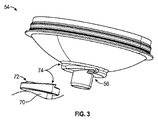
本開示の態様は、スプレーガンと収容容器との間の解放可能なシール接続を容易にする、コネクタシステムを対象とする。背景技術として、図1は、重力送り式のスプレーガン30及び収容容器32を含むスプレーガン塗装システム20を示している。ガン30は、本体40と、ハンドル42と、本体40の前端部のスプレーノズル44とを含んでいる。ガン30は、本体40の両側に枢動的に装着されたトリガ46によって、手動で操作される。入口ポート48(おおまかに示される)は、本体40に形成されるか又は本体40によって担持され、スプレーガン30の(隠れている)内部スプレー導管と、収容容器32との間の流体接続を確立するように構成される。収容容器32は、スプレーされる液体(例えば、塗料)を収容しており、入口ポート48に接続されている(図1の図で示される接続が必ずしも本開示のコネクタシステムを反映していないことを理解されたい)。使用時には、スプレーガン30はハンドル42の下端部のコネクタ49を介して圧縮空気源(図示せず)に接続される。使用者がトリガ46を引くと、ガン30を介して圧縮空気が送達され、塗料が重力を受けて収容容器32からスプレーガン30を経てノズル44に送達される。その結果、塗料(又は他の液体)はノズル44を離れる際に霧化され、ノズル44を離れる圧縮空気と共にスプレーを形成する。
Aspects of the present disclosure are directed to connector systems that facilitate an open seal connection between a spray gun and a containment vessel. As a background technique, FIG. 1 shows a spray
図示を容易にするために、スプレーガン30と収容容器32との間の、本開示の接続形態は図1の図には含まれない。一般的に、収容容器32は、スプレーガン30に接続する第1の接続形態を確立する1つ以上の構成部品を含む。相補的な第2の接続形態は、収容容器32と入口ポート48との間に組み付けられたアダプタ(図示せず)に、又はスプレーガン30に含まれる。この背景技術を念頭に置き、図2は、本開示の原理による収容容器50の非限定的な1つの例を図示する。収容容器50は、外側容器52及び蓋54を含む。蓋54は、下記でより詳細に説明する、第1の接続形態又は特徴部56(おおまかに示される)を含むか、又は設ける。他の実施形態において、第1の接続形態又は特徴部56は、収容容器50の任意の他の構成部品に設けることができる。すなわち、下記の説明は本開示の接続形態を収容容器の蓋の一部として表すが、このように表された接続形態は、蓋のほかに、代替的に任意の他の収容容器構成部品に設けることができる。収容容器50の残りの構成部品は様々な形態を取ることができ、任意である。例えばいくつかの実施形態において、収容容器50は、ライナー58及びカラー60を更に含む。一般的に、ライナー58は、容器52の内部に嵌合し、容器52の上縁部に着座する開放端に、狭いリム62を有することができる。蓋54は、ライナー58の開放端の上又は中に嵌合するように構成され、蓋54の周縁部がライナー58のリム62上に位置される。蓋/ライナー組立体は、容器52に解放可能に係合(例えば、示されているねじ付き境界面、スナップフィット等)する環状カラー60によって、所定の位置に固定される。
For ease of illustration, the connections of the present disclosure between the
接続形態56に加えて、蓋54は、ライナー58に収容された液体が流れることができる液体出口64(おおまかに示される)を形成する。使用中、ライナー58は、塗料が収容容器50から出されると、軸方向に蓋54へ向かって潰れる。ライナー58が潰れると、空気が外側容器に入ってくる(本実施形態では、外側容器52任意の通気穴66を通って)。スプレーが完了すると、収容容器50をスプレーガン30(図1)から分離することができ、カラー60が取り出され、蓋/ライナー組立体は1つの部品として外側容器52から取り外すことができる。外側容器52及びカラー60は清潔なままであり、新しいライナー58及び蓋54を用いて再使用できる状態にある。これにより、収容容器50の過度な洗浄を回避することができる。
In addition to the
他の実施形態において、本開示の収容容器は、ライナー58及び/又はカラー60を含む必要がない。いくつかの実施形態において、収容容器は外側容器を含む必要がない(例えば、蓋及びライナーは外側容器から分離又は取り外し可能であってよく、そのためスプレー中に外側容器が必要なくなる)。本開示の接続形態は、これらを用いて、及び/又は図によって直接的に関連され得る、若しくは関連され得ない、他の多くの収容容器構成を用いて実行され得る。
In other embodiments, the containing container of the present disclosure need not include a
上述のように、蓋54に設けられた第1の接続形態56は、スプレーガン入口又は装置に設けられた相補的な第2の接続形態と、解放可能に接続するように構成されている。参照として、図3は、スプレーガン入口70の一部と共に蓋54を図示し、スプレーガン入口70は別途、第2の相補的接続形態72(おおまかに示される)を担持又は設ける。スプレーガン入口70は、アダプタ、スプレーガンの着脱可能なスプレーヘッド組立体(例えば、その開示内容全体が本明細書に参照として組み込まれる、「spray head assembly 60」と題された、Escotoらによる米国特許第8,590,809号を参照されたい)に設けられたスプレーガン30の一体部分(図1)などであってもよい。それとは関係なく、第1及び第2の接続形態56、72は連係するように構成され、蓋54とスプレーガン入口70との間の、解放可能で液体密でシールされた装着又は接続を促進する。いくつかの実施形態において、第1及び第2の相補的接続形態56、72は、本開示の原理によるスプレーガンの収容容器コネクタシステム74を共同で画定するものと見做すことができる。
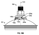
As described above, the
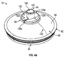
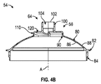
上述のように、第1の接続形態56は蓋54の一部として設けることができる。いくつかの実施形態において、図4A及び図4B(蓋54を単独で図示)に示すように、蓋54の形状は、長手方向軸Aを画定するものとして見做すことができる。第1の接続形態56(おおまかに示される)及び液体出口64に加えて、蓋54は、壁80、フランジ82、及びハブ84を含むか、又は画定する。壁80は、互いに反対にある内面86及び外面88を画定し、壁80の少なくとも外面88は、例えば(しかし非限定で)図に示された、湾曲した(例えば半球形などの)形状を有する。最終的に、壁80は、好ましくは長手方向軸Aと同軸である中央開口部90(図4Bに最もよく示される)を画定する。フランジ82は、中央開口部90と反対側の壁80の外周から径方向外側に突出し、例えば外側容器52(図2)などの、収容容器50(図2)の1つ以上の他の構成部品と整合するように構成され得る。示された実施形態において、ハブ84は、壁80の反対方向に、フランジ82から(長手方向軸Aに対して)長手方向に突出し、例えばライナー58(図2)など収容容器50の1つ以上の他の構成部品と整合するように構成され得る。壁80、フランジ82、及びハブ84は、多様な他の形態を取ることができる。更に他の実施形態において、フランジ82及びハブ84の一方又は両方を省略することができる。
As described above, the
液体出口64は、流れ口100を含む。流れ口100は、好ましくは長手方向軸Aと同軸であり、この場合壁80に対して上方(図4A及び図4Bの向きに対して)に突出し、先端面102で終端する。他の実施形態において、流れ口100は蓋54の本体内に収容されてもよく、又は蓋54の外面88の凹部から成ってもよい。流れ口100は、中央開口部90と位置合わせされ、かつ開口している通路104(図4Bに最もよく示される)を画定する。この構成によって、液体出口64を通る液体の流れ(例えば壁80の内面86領域内の位置から流れ口100の外側位置まで)が、中央開口部90及び通路104を通して容易に生じる。
The
いくつかの実施形態において、液体出口64は、第1の接続形態56の構成部品であると任意に見做される1つ以上の追加の特徴部を含む。例えば、先端面102は、蓋54に組み付ける際に、相補的な構成部品又はデバイス(例えば図3のスプレーガン入口70)と端面シールを形成するように構成され得る。シール関係は、長手方向軸Aに対して垂直な面内で実質的に平坦若しくは平面(すなわち、真の平坦若しくは平面形状の5%以内)である先端面102によって、又はテーパーが付くか若しくは面取りされて、相補的な構成部品の対応するテーパーが付いた面に対してシールするように構成された先端面102によって確立され得る。蓋54とスプレーガン入口70との間の液体密シールは、先端面102(例えば、流れ口100若しくは相補的構成部品の中又は上に形成されたリング、Oリング、摩擦、又は締まり嵌めなど)を含み得るか、又は含み得ない種々の他の構造によって代替的に促進され得る。
In some embodiments, the
上記の背景技術に対して、図5A〜図5Cを更に参照すると、第1の接続形態56(おおまかに示される)は、プラットフォーム110を含む。プラットフォーム110は、流れ口100の外側位置における、壁80の外面88からの突出部として見做すことができる。いくつかの実施形態において、壁80及びプラットフォーム110は、一体の連続構造として形成することができ、プラットフォーム110の形状は、フランジ82からの延長にある壁80によって画定された湾曲形状から逸れていることを表している。更に、図4Bに最もよく示されるように、流れ口100及びプラットフォーム110は、いくつかの実施形態において一体の連続構造としても形成され得る。それとは関係なく、プラットフォーム110は、以下で説明するように、第2の相補的接続形態72(図3)との選択的な接続又は装着を容易にするように構成される。
Further referring to FIGS. 5A-5C with respect to the above background techniques, the first connection form 56 (generally shown) includes the
プラットフォーム110は、外面88から延びて、コネクタ構造120(おおまかに示される)で終端する。コネクタ構造120は、スプレーガン入口(図示せず)との間にスライドする境界面を設けるように構成され、壁80の任意の湾曲形状と異なる形状を有し得る。コネクタ構造120は、流れ口100を周方向に取り囲む(例えば、コネクタ構造120は、流れ口100の径方向外側の位置において、長手方向軸Aを中心に全体的に回転する)。コネクタ構造120の外形特徴部は、相補的な第2の接続形態72(図3)の対応する特徴部との係合を容易にするように構成される。
The
例えば、1つ以上のトラッピング領域又はアンダーカット(図4A〜図5Cの非限定の実施形態で図示された、第1及び第2のトラッピング領域又はアンダーカット130a、130bなど)が、1つ以上の接触面又は支え面(図4A〜図5Cの非限定の実施形態で図示された、第1及び第2の接触面又は支え面132a、132bなど)と共にコネクタ構造120内に画定される。2つのアンダーカット130a、130b、及び2つの接触面132a、132bが設けられた、示された非限定の例では、流れ口100を中心としたコネクタ構造120の回転によって画定される回転方向(すなわち時計回り、又は反時計回り)に対して、第1の接触面132aは、第1のアンダーカット130aから第2のアンダーカット130bまで時計回りで周方向に延び、誘導領域134a及び傾斜領域136aを生成する外形を有する。このとき、誘導領域134aは、時計回り方向に対して傾斜領域136aよりも「前」又は「上流」にある。同様に、第2の接触面132bは、第2のアンダーカット130bから第1のアンダーカット130aまで時計回りで周方向に延びてよく、誘導領域134b及び傾斜領域136bを生成する外形を有する。更に他の実施形態において、任意の第2の接触面132bは、第1の接触面132aとは異なる構造であってもよく、誘導領域134b及び傾斜領域136bのうちの一方又は両方を含んでもよいし、含まなくてもよい。更に他の実施形態において、3つ以上の接触面(及び/又は3つのアンダーカット)が設けられる場合、第1の接触面130aは誘導領域134a及び傾斜領域136aを有し得る一方で、残りの接触面は第1の接触面130aと同一であっても、又は異なる構造であってもよい。
For example, one or more trapping regions or undercuts (first and second trapping regions or undercuts 130a, 130b, etc. illustrated in the non-limiting embodiments of FIGS. 4A-5C) are one or more. It is defined in the
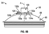
(2つが設けられる場合の)接触面132a、132bは、いくつかの実施形態において実質的に同一であってよく、そのため第1の接触面132aの以下の説明は、同様に第2の接触面132bに適用される。誘導領域134aの主面は、実質的に平坦(すなわち真の平坦形状の5%以内)、かつ実質的に長手方向軸Aに対して垂直(すなわち真の垂直関係の5%以内)であり得る。傾斜領域136aは、誘導領域134aから第2のアンダーカット130aまでの範囲において、(図5B及び図5Cの直立方向に対して)長手方向下方にテーパーが付いており、螺旋形状の一部を作り出す。これにより、誘導領域134aは、長手方向又は垂直方向で(図5B及び図5Cの直立方向に対して)傾斜領域136aの「上」にあり、傾斜領域136aの主面は、誘導領域134aの主面に対して斜め(長手方向軸Aに対して実質的に垂直ではない)になる。例えば図6に示される傾斜領域136a、136bは、傾いた直線として描かれているが、本開示の範囲内で異なる軌跡(例えば、曲線や部分的に曲線)が可能であることを理解されたい。
The contact surfaces 132a, 132b (when two are provided) may be substantially the same in some embodiments, so the following description of the
第1アンダーカット130aによって生じた外形特徴部は図6に示されるが、第2のアンダーカット130b(図4A)が(設けられる場合)実質的に同一の構成を有し得ることが理解される。上記の説明と同様、第1アンダーカット130aが、第2の接触面132bの傾斜領域136bと第1の接触面132aの誘導領域134aとの間の移行部に形成されるか、又は移行部を画定する。肩部又は保持特徴部140aが、アンダーカット130aによって画定され、第1の接触面132aの先端部142と第2の接触面132bの終端部144との間に延びる。肩部140aの主面は、誘導領域134aの主面に対して、かつ傾斜領域136bの主面に対して非平行であり、肩部140aは、第2の接触面の傾斜領域136bの上で外側に突出している。肩部140aの形状は、軸方向保持面146及び停止面148を画定するものと見做すことができる。
The external features created by the first undercut 130a are shown in FIG. 6, but it is understood that the second undercut 130b (FIG. 4A) can have substantially the same configuration (if provided). .. Similar to the above description, the first undercut 130a is formed in the transition portion between the
図4A〜図5Cに戻ると、第1の接続形態56は2つのアンダーカット130a、130b(及び2つの接触面132a、132b)を含むように表されているが、他の実施形態において、1つ又は3つ以上のアンダーカット(及び対応する数の接触面)が形成され得る。いくつかの実施形態において、2つ以上が設けられる場合、アンダーカット130a、130bはコネクタ構造120の円周に沿って等間隔で配置されてもよい。更に、プラットフォーム110及びコネクタ構造120は、本質的に円形であるものと示しているが、他の形状も許容される。例えば、コネクタ構造120の形状は、楕円、多角形、これらの組み合わせ等の複雑な形状などとすることができる。
Returning to FIGS. 4A-5C, the
いくつかの実施形態において、蓋54(したがって第1の接続形態56)は、プラスチック射出成形された構成部品である。これらの状況下で、アンダーカット130a、130bは、従来の射出成形システムを用いて容易に生成され、アンダーカット130a、130bは、工具スライド経路若しくはスライド方向に沿って、又は位置合わせされて、位置を決められる。例えば、図4Aの非限定的例に関しては、アンダーカット130a、130bは、いくつかの実施形態において、射出成形工具の見切り線(図4Aの150で識別される)に対して垂直に、及び工具のスライドと位置合わせして、位置を決められてよい。このように、アンダーカット130a、130b(及び本開示の接続形態に関連付けられた他の特徴部)は、従来の射出成形工具形態への複雑で重要な変更を必要としない射出成形を用いて、非常に実用的である。他の製造技術及び材料も許容され、本開示の蓋(及び対応する接続形態)は、プラスチック射出成形に限定されない。 In some embodiments, the lid 54 (and thus the first connection form 56) is a plastic injection molded component. Under these circumstances, the undercuts 130a, 130b are easily generated using a conventional injection molding system, and the undercuts 130a, 130b are positioned along or aligned with the tool slide path or slide direction. Can be decided. For example, with respect to the non-limiting example of FIG. 4A, the undercuts 130a, 130b, in some embodiments, are perpendicular to the parting line of the injection molding tool (identified by 150 in FIG. 4A) and the tool. The position may be determined by aligning with the slide of. Thus, the undercuts 130a, 130b (and other features associated with the connection modes of the present disclosure) use injection molding that does not require complex and significant changes to conventional injection molding tool forms. Very practical. Other manufacturing techniques and materials are also acceptable, and the lids (and corresponding connection forms) of the present disclosure are not limited to plastic injection molding.
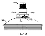
図3に戻ると、第2の接続形態72は、第1の接続形態56の特徴部と選択的に嵌合するように構成される。いくつかの実施形態において、第2の接続形態72は、図7に示すアダプタ180などのアダプタの一部として設けられる。第2の接続形態72(図7に大まかに示される)に加えて、アダプタ180は、管状部材190を含む。様々な構成部品の詳細を以下に示す。一般的に、アダプタ180の形状は中心軸Xを画定する。管状部材190は、スプレーガン入口ポートへの接続を確立するためなど、従来のスプレーガンの収容容器接続アダプタと同種の特徴部を含ことができる、又は設けることができる。第2接続形態72のベース192は、管状部材190から突出し、第2の接続形態72の他の部分を担持又は画定し、アダプタ180の蓋54への装着を促進する(図3)。
Returning to FIG. 3, the
管状部材190は、種々の形態を取ることができ、中央通路200(図7では隠れているが、例えば図8Dに示される)を画定する。通路200は、管状部材190の先端部202において開口している。管状部材190は、従来の(例えば、ねじ切りされた)スプレーガン入口ポートへの組み付けを容易にする、装着特徴部を形成するか又は設ける。例えば、外側ねじ204は、先端部202に隣接する管状部材190に沿って設けられてよく、スプレーガン入口ポートによって設けられたねじと、ねじ接続するように構成される。このとき、外側ねじ204のピッチ、輪郭、及び間隔は、アダプタ180と使用するよう意図されたスプレーガンのメーカー/型の特定のねじパターンに従って選択され得る。外部ねじ202を含み得る若しくは要し得る、又は含まないか若しくは要さない、他のスプレーガンの装着特徴部が同様に許容される。管状部材190は、任意で把持部206を更に含むか、又は画定できる。把持部206は、使用者が従来の工具を用いてアダプタ180を操作するのを容易にするように構成され、いくつかの実施形態において、レンチによって容易に係合するようになっている六角形の表面パターンを含むか、又は画定する。他の実施形態において、把持部206を省略することができる(例えば、六角又は同様の形状の表面を設ける必要がない)。
The
図8A〜図8Dを参照すると、ベース192は、先端部202の反対側の管状部材190から延び、リング210及びフランジ212を含む。フランジ212は、以下で説明するように、コネクタ構造214(おおまかに示される)を形成する。図8Dに最もよく示されるように、リング210及びフランジ212は、チャンバ216を画定するよう組み合わされる。チャンバ216は、管状部材190の中央通路200に開口し、蓋54(図4A)の流れ口100(図4A)を受け入れるように構成される。チャンバ216の径は、流れ口100(図4A)の外径に対応しており、流れ口100を摺動可能に受け入れるように選択される。フランジ212は、管状部材190と反対の、リング210の外周から長手方向に突出し、コネクタ構造214で終端する。
With reference to FIGS. 8A-8D, the
コネクタ構造214の外形特徴部は、第1の接続形態56(図4A)のコネクタ構造120(図4A)に関する上述の外形特徴部と同等である。例えば、1つ以上のトラッピング領域又はアンダーカット(図7〜図8Dの非限定の実施形態で図示された、第1及び第2のトラッピング領域又はアンダーカット230a、230bなど)が、コネクタ構造214に沿って形成され、1つ以上の接触面又は支え面(図7〜図8Dの非限定の実施形態で図示された、第1及び第2の接触面又は支え面232a、232bなど)を生成する。(2つ設けられる場合の)接触面232a、232bの形状は、上述のように第1の接続形態の接触面132a、132bに対応し、接触面232a、232bのうちの少なくとも一方、任意で両方の各々は、誘導部234a、234b、及び傾斜部236a、236bを含むか、又は画定する。(2つ設けられる場合の)アンダーカット230a、230bの周方向位置及び形状は、上述のように第1の接続形態のアンダーカット130a、130b(図5A)に対応する。アンダーカット230a、230bのうちの少なくとも一方、任意で両方の形状は、第1の接触面232aと第2の接触面232bとの間の移行部に、指部又は保持特徴部240a、240bを確立する。例えば、図8Dに示されるように、第1のアンダーカット230aで画定された指部240aは、第1の接触面232aの先端部242と、第2の接触面232bの終端部244との間に延びる。指部240aの主面は、誘導部234aの主面に対して、かつ傾斜部236bの主面に対して非平行であり、指部240aは、第2の接触面の傾斜部236bの外側に突出する。図6を更に参照すると、誘導部234aの主面に対する指部240aの角度方向は、誘導領域134aに対する肩部140aの角度方向に対応する。指部240aの形状は、軸方向保持面246及び停止面248を画定するものと見做すことができる。
The external feature portion of the
図8A〜図8Dに戻ると、第2の接続形態72は、2つのアンダーカット230a、230b(及び2つの接触面232a、232b)を含んでいるように示されているが、他の実施形態において、第1の接続形態56(図4A)のアンダーカット構造に対応する、1つ又は3つ以上のアンダーカット(及び対応する数の接触面)が形成され得る。更に、ベース192及びコネクタ構造214は、本質的に円形であるものとして示されているが、第1の接続形態56の形状に対応する他の形状も許容される。
Returning to FIGS. 8A-8D, the
図9を参照すると、第1の接続形態56と第2の接続形態72との間(すなわち蓋54とアダプタ180との間)の係合は、最初にアダプタ180を液体出口64に位置合わせすることを必要とする。蓋54及びアダプタ180は、アダプタ180のコネクタ構造214が蓋54のコネクタ構造120と対向するように空間的に配置され、アダプタのアンダーカット230a、230b(そのうちの1つが図9に見える)が、蓋のアンダーカット130a、130bから回転的にオフセットされる(例えば、図9の配置において第1の指部240aは第2の接触面132bの誘導領域134bに概ね位置合わせされる)。
Referring to FIG. 9, the engagement between the
次に蓋54及びアダプタ180は、互いに向かって方向付けられ、図10A〜図10Cに示されるように、アダプタ180のコネクタ構造214を蓋54のコネクタ構造120に接触させる。蓋54の流れ口100は、アダプタ180のチャンバ216内に摺動可能に受け入れられ、蓋54の長手方向軸Aがアダプタ180の中心軸Xに位置合わせされる。回転による位置ずれのため、アダプタのコネクタ構造214は、最初は蓋のコネクタ構造120とかみ合わない。例えば、図10A及び図10Bは、第1の指部240aが、第1の肩部140aから回転的にオフセットされ、第2の接触面132aの誘導領域134bに載るか、又は接触することを図示している。図面内で直接視認することはできないが、同様の関係が、第2の指部240bと第1の接触面132aとの間に確立される。図10A〜図10Cの初期の組立状態において、アダプタのアンダーカット230a、230b及び指部240a、240bは、蓋のアンダーカット130a、130bの垂直方向の「上」にある。
The
次にアダプタ180を蓋54に対して回転させ(及び/又はその逆)、一方で少なくとも僅かな圧縮力(例えば重力、使用者が加える力など)が維持されて、アダプタの指部240a、240bの各々を、蓋のアンダーカット130a、130bのうちの対応する1つに向けて方向付ける。例えば、図11に示されるように、アダプタ180は、指部240aが蓋の第1のアンダーカット130aに接近する(及び後にその中に入る)ように、(例えば時計回りに)回転されている。アダプタの第2の接触面232bの傾斜部236bと、蓋の第2の接触面132bの蓋の傾斜領域136bとの間のスライド境界面(及び対応する螺旋のような形状)のため、アダプタ180が回転されると、アダプタ180は蓋54に対して垂直方向に落ちるか又は下がり、それによって指部240aは蓋のアンダーカット130aに近づき、指部240aは蓋の肩部140aと位置合わせされる。
The
蓋54に対するアダプタ180の回転(及び/又はその逆)を続けると、蓋のコネクタ構造120(図9)は、アダプタのコネクタ構造214(図9)を、対応するアンダーカット130a、130b、230a、230bの箇所で堅固に係合させる。図12A及び図12Bは、実現された蓋54及びアダプタ180のロック状態を示している。図示のように、アダプタの第1の指部240aは蓋の第1のアンダーカット130a内に入り、蓋の第1の肩部140aはアダプタの第1のアンダーカット230a内に入り、アダプタの第1の指部240aは蓋の第1の肩部140aに載る。視認できないが、蓋の第2のアンダーカット130bとアダプタの第2のアンダーカット230bとの間の境界面にも、同様の関係がある。蓋54内の液体は、通路104、チャンバ216、及び通路200において確立された流体接続を介して、アダプタ180を容易に流れ過ぎる。
Continuing the rotation of the
より一般的には、図9を更に参照すると、蓋54はアダプタ180上で回転され(及び/又はその逆)、蓋の傾斜領域136a、136bと、対応するアダプタの傾斜部236a,236bとの間の境界面は、蓋のアンダーカット130a、130bを、対応した嵌合するアダプタのアンダーカット230a、230bに(及びその逆に)誘導する。回転軸に垂直な面に対する肩部140a、140bの下方への角度方向(回転方向)のため、指部240a、240bが対応する肩部140a,140bに沿って漸次的に進むと、アダプタ180が蓋54の上に向かって(図9、図12Aの向きに対して)下方に引っ張られるか、又は引き寄せられることが強制され、構成部品間の液体密シールを促進する。アンダーカット130a,130b、230a、230bは、蓋54に対するアダプタ180の回転運動(及び/又はその逆)に対する端部停止として作用する。図6及び図8Dを更に参照すると、軸方向保持は、肩部140a、140bの軸方向保持面146と、対応する指部240a,240bの軸方向保持面246との間の境界面によって実現される。回転停止は、肩部140a,140bと、対応した指部240a、240bの停止面248との間、及び指部240a、240bと、対応した肩部140a、140bの停止面148との間の接触によってもたらされる。
More generally, with reference to FIG. 9, the
対応する蓋のアンダーカット130a、130bとアダプタのアンダーカット230a、230bとの間の係合は、アダプタ180の蓋54に対する保持をもたらし、更に、蓋のコネクタ構造120とアダプタのコネクタ構造214との間の境界面は、長手方向軸Aに対して垂直の軸における、アダプタ180上の蓋54(及びその逆)の安定性をもたらす。いくつかの実施形態において、コネクタ構造120、214の傾斜する外形は、軸方向回転を介して蓋54をアダプタ180から連結解除するのを容易にする。これに関して、いくつかの実施形態において、ロック状態の蓋54とアダプタ180との間の液体密シールを促進する、シール機能を設け得ることが想起される。液体密シールは破断しにくくすることができる。しかし、ロック状態からアダプタ180が蓋54に対して回転すると、アダプタ180は持ち上げられてシール機能を解除し、アダプタ180を蓋54から取り外すのを補助する。
The engagement between the corresponding lid undercuts 130a, 130b and the adapter undercuts 230a, 230b provides retention of the
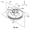
接続形態56、72の特徴及び構成は、様々な平面を参照して代替的に説明することができる。例えば図13Aは、X、Y、Z座標の指示と共に図4Aの蓋54の図を再現する。Z軸又はZ方向は、長手方向軸Aを含む(又は平行である)。X及びY軸(又は方向)はZ軸に対して直交し、かつ互いに直交する。中心線面CPは、X、Z面に画定され、長手方向軸Aを含む(又は平行である)。換言すると、中心線面CPは長手方向軸Aを通る。2つのトラッピング領域又はアンダーカット130a、130bが等間隔で設けられた、図13Aの非限定の一実施形態では、中心線面CPは、2つのトラッピング領域130a、130bの間の中央に置かれ得る。この配置は、図13Bの上面図(それ以外では図5Aの再現)で更に反映される。図13A及び図13Bを続けて参照すると、取り付け面APは中心線面CPに直交するよう更に画定される(すなわち、取り付け面APはX,Y面内に画定される)。いくつかの実施形態において、取り付け面APは、支え面又は接触面132a、132bの各々における誘導領域134a、134bの主面を含む。取り付け面APのこの1つの位置は、図13C(それ以外では図5Bの再現)及び図13D(それ以外では図5Cの再現)に更に明示される。最後に、図13Bは、上述のようにロック状態へ移行するときの、アダプタ180(図7)が蓋54に対して回転する収納方向を、矢印RDで示す。
The features and configurations of the connection forms 56, 72 can be described in an alternative manner with reference to various planes. For example, FIG. 13A reproduces the figure of
上記の規定を念頭に、外面88は液体出口64から離れる方へ延び、いくつかの実施形態においては、取り付け面APに概ね平行(すなわち、真の平行関係の10%以内)の方向に、中心線面CPから離れる方へ延びている保持特徴部(例えば、対応するトラッピング領域130a、130bに関連付けられた保持特徴部、又は肩部140a,140b)のうちの1つ以上を含むものと見做され得る。この関係は図13A及び図13Bに最もよく示される。保持特徴部140a、140bは、外面88内で凹んでいるか、又は外面88から突出しているものと考えることができる。他の実施形態において、保持特徴部140a、140bは、対応する接触面132a、132bの誘導領域134a、134b内で凹んでいるか(例えば図13Eは、保持特徴部140aが第1の接触面132aの誘導領域134aに対して凹んでいることを反映している)、又は対応する接触面132a、132bの傾斜領域136a、136bから突出している(例えば図13Eは、保持特徴部140aが第2の接触面132bの傾斜領域136bから突出していることを反映している)と、考えることができる。
With the above provisions in mind, the
図13A〜図13Eを参照すると、保持特徴部の角度αは、中心線面CPと対応する保持特徴部140a、140bの停止面148との間で画定される。停止面148は、図13A〜図13Dの図では概ね隠されているが、図13Eで保持特徴部140aとして確認できる。特に図13A及び図13Bを参照すると、保持特徴部の角度αは、いくつかの実施形態において90°以上である。更に、停止面148は、保持特徴部の角度αの範囲内で、及び、別の状況では概ね取り付け面APに沿って画定される収納方向RDから、接近可能である。この関係は、図13Eで更に明示される。図13Eは、いくつかの実施形態において、保持特徴部140aの軸方向保持面146が、取り付け面APに対して鋭角で配置又は配設され、それによってトラッピング領域130aが、方向軸保持面146と外面88との間に(例えば第2の接触面132bに沿って)形成されることも強調している。上記の面及び角度は、第2の接続形態72(図3)に同様に適用できる。
With reference to FIGS. 13A to 13E, the angle α of the holding feature portion is defined between the centerline surface CP and the stop surfaces 148 of the corresponding
保持特徴部の角度αは、上述のように、蓋54の任意のプラスチック射出成形特質を支持することができる。例えば、蓋54が、二つ割り型から形成されたプラスチック射出成形された構成部品である任意の実施形態では、中心線面CPは見切り線150(図4A)で画定されるものと見做してよい。したがって、90°以上の保持特徴部の角度αは、第1及び第2のトラッピング領域130a、130bが、工具のスライド経路、又は二つ割り型のスライド方向に位置合わせされ得ることを反映する。他の実施形態において、プラスチック射出形成工具が、3つ以上の金型部品を含み得ることが想定され、保持特徴部の角度αは、トラッピング領域をスライド方向又は金型部品の工具のスライド経路に位置合わせするのを促進するために適切な、対応する寸法以上である。例えば、三つ割り型を用いると、保持特徴部の角度αは60°以上であり、四つ割り型を用いると、保持特徴部の角度は45°以上、などとなる。
The angle α of the retention feature can support any plastic injection molding property of the
上記の説明では、相補的な第2の接続形態72(図7に全体的に参照)をアダプタ180の一部として設けているが、他の構成も許容される。例えば、第2の接続形態72が、スプレーガンの一体部品として恒久的に組み付けられているか、又は設けられている(例えば上述の第2の接続形態72が、スプレーガン30(図1)の入口ポート48(図1)として設けられるか、又は入口ポート48に設けられ得る)。
In the above description, a complementary second connection form 72 (see overall in FIG. 7) is provided as part of the
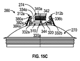
いくつかの実施形態において、ロック状態のコネクタ構造120、214の(すなわちアンダーカット130a、130b、230a、230bでの)間の係合が、蓋54とアダプタ180との間の保持の主な形状として働くことができるか、又はそのような形状を提供することができる。本開示の原理による他の実施形態において、保持部の主な形態として働くか、又は働かない、1つ以上の追加の接続特徴部が含まれてもよい。例えば図14は、本開示の原理による相補的な第1及び第2の接続形態252、254(おおまかに示される)を含む、別のスプレーガンの収容容器コネクタシステム250の部分を図示する。第1の接続形態252は蓋260の一部として設けられ、第2の接続形態254はスプレーガンの液体入口の一部として設けられており、示されているアダプタ262がスプレーガンに接続するようになっている。
In some embodiments, the engagement between the locked
蓋260は図15A〜図15Dでより詳細に示され、多くの点で上述の蓋54(図4A)と類似し得る。蓋260は一般に、壁270及び液体出口272を含む。液体出口272は、流れ口274の先端面276及び/又は先端面276の近傍の流れ口274の外側に沿って形成された、もう1つの環状リブ278などの、任意のシール機能を伴う流れ口274を含む。
The
第1の接続形態252(図15Aに大まかに示される)は、プラットフォーム310、及び少なくとも1つの保持部材(図14〜図15Dの非限定の実施形態に図示された、第1及び第2の保持部材312a、312bなど)を含む。一般的に、プラットフォーム310は、上述のプラットフォーム110(図4A)とかなり類似することがあり、コネクタ構造320で終端するか、又はコネクタ構造320を形成する。コネクタ構造320は、コネクタ構造120(図4A)と類似してよく、少なくとも1つのトラッピング領域又はアンダーカット(図14〜図15Dの非限定の実施形態で図示された、第1及び第2のトラッピング領域即ちアンダーカット330a、330bなど)を画定する外形特徴部をもたらす。保持部材312a、312bは、アンダーカット330a、330bから周方向にオフセットされ、以下で説明するように、第2の接続形態254(図13)と選択的なロック係合をもたらす。
The first connection form 252 (roughly shown in FIG. 15A) is a
先行の説明と同様、(2つ設けられる場合の)第1及び第2のアンダーカット330a、330bは、コネクタ構造320で画定され、少なくとも1つの接触面又は支え面(図14〜図15Dで非限定の実施形態で図示された、第1及び第2の接触面又は支え面332a、332bなど)はアンダーカット330a、330bの間で形成又は画定される。流れ口274を中心としてコネクタ構造320の回転によって画定された回転方向(すなわち時計回り、又は反時計回り)に対して、第1の接触面332aは第1のアンダーカット330aから第2のアンダーカット330bまで、時計回りの周方向に延び、誘導領域334a及び傾斜領域336aを生成する外形を有する。時計回り方向に対して、誘導領域334aは傾斜領域336aよりも「前」又は「上流」にある。第2の接触面332b(又は任意の追加の接触面)は、第1の接触面332aと同様であり得る。この場合、第2の接触面332bは第2のアンダーカット330bから第1のアンダーカット330aまで、時計回りの周方向に延び、誘導領域334b及び傾斜領域336bを生成する外形を有する。
Similar to the previous description, the first and
(2つが設けられる場合の)接触面332a、332bは、いくつかの実施形態において実質的に同一であってよく、そのため第2の接触面332bの以下の説明は、同様に第1の接触面332aに適用される。図16の断面図に最もよく反映されるように、誘導領域334bの主面は、実質的に平坦(すなわち真の平坦形状の5%以内)、かつ長手方向軸Aに対して実質的に垂直(すなわち真の垂直関係の5%以内)であり得る。傾斜領域336bは、誘導領域334bから第1のアンダーカット330aまでの範囲で、(図16の概ね直立方向に対して)長手方向下方にテーパーが付いており、螺旋形状の一部を作り出す。これにより、誘導領域334bは、傾斜領域336bの長手方向又は垂直方向で(図16の概ね直立方向に対して)「上」となり、傾斜領域336bの主面は、誘導領域334bの主面に対して斜め(長手方向軸Aに対して実質的に垂直ではない)である。
The contact surfaces 332a and 332b (if two are provided) may be substantially the same in some embodiments, so the following description of the
第1アンダーカット330aによって生じた外形特徴部は、図15Cに示され、第2のアンダーカット330b(図15B)が実質的に同一の構成を有し得ることが理解される。上記の説明と同様、第1アンダーカット330aが、第2の接触面332bの傾斜領域336bと第1の接触面332aの誘導領域334aとの間の移行部に形成されるか、又は移行部を画定する。肩部又は保持特徴部340aが、アンダーカット330aによって画定され、第1の接触面332aの先端部342と第2の接触面332bの終端部344との間に延びる。肩部340aの主面は、誘導領域334aの主面に対して、かつ傾斜領域336bの主面に対して非平行であり、肩部340aは、第2の接触面の傾斜領域336bの上で外側に突出している。上述のように、肩部340aは軸方向保持面及び停止面を画定することができる。
The external features created by the first undercut 330a are shown in FIG. 15C, and it is understood that the second undercut 330b (FIG. 15B) can have substantially the same configuration. Similar to the above description, the first undercut 330a is formed at the transition portion between the
図15A〜図15Dを続けて参照すると、第1の接続形態252は2つのアンダーカット330a、330b(及び2つの保持部材312a、312b)を含むように表されているが、他の実施形態において、1つ又は3つ以上のアンダーカット(及び対応する数の保持部材)が形成され得る。いくつかの実施形態において、2つ以上が設けられる場合、アンダーカット330a、330bはコネクタ構造320の円周に沿って等間隔で配置されてもよい。更に、プラットフォーム310及びコネクタ構造320は、本質的に円形であるものとして示しているが、他の形状も許容される。例えば、コネクタ構造体320の形状は、楕円、多角形、これらの組み合わせ等の複雑な形状などとすることができる。
With reference to FIGS. 15A-15D in succession, the
(2つ以上設けられている場合の)保持部材312a、312bは、第1の保持部材312aの以下の説明が第2の保持部材312bに等しく適用されるように、同一のものであってよい。上述した回転方向に対し、第1の保持部材312aは、反対側にある第1及び第2の端部370a、372aを画定するものと見做すことができる。保持部材312aは、アーム380a及びタブ382aを含む。アーム380aは、流れ口274から径方向に間隔があけられ、かつ壁270から上方に突出する。1つ以上の補強支柱384aが、アーム380aと壁270の間に任意で設けられ、アーム380aを、示された直立方向に付勢又は補強する役割を担う。タブ382aは、壁270の反対側のアーム380aから径方向内側に突出する。図17A〜図17Cで最もよく示されるように、第1の保持部材312aは第1の接触面332aに関連付けられ、捕捉領域386aは、第2の接続形態254(図14)の対応する特徴部を受け入れるために、接触面332a、アーム380a、及びタブ382aによって画定される。
The holding
より詳細には、アーム380aの突出が係合面388を画定する。係合面388は、流れ口274に面し、かつ流れ口274から径方向に間隔があけられる。タブ382aは、係合面388に対して半径方向内側に突出し、ガイド面390及び位置合わせ面392を画定する。ガイド面390は接触面332aに面し、長手方向の間隔Lだけ接触面332aから長手方向に間隔をあけられる。接触面332a、係合面388、及びガイド面390は組み合わさって捕捉領域386aを画定する。位置合わせ面392は、流れ口274に面し、かつ流れ口274から径方向に間隔があけられる。長手方向軸Aに対する係合面388及び位置合わせ面392の寸法は、アダプタ262(図14)の外形特徴部に対応する。このとき、特に図17Aを参照すると、係合面388は、下記で説明する所望の連結及び連結解除操作を容易にするための、アダプタ262の外形特徴部に従って選択された捕捉径Dを、長手方向軸Aに対して共同で画定する。
More specifically, the protrusion of the
接触面332a及び保持部材312aの外形は、捕捉領域386a内の第2の接続形態254の対応する特徴部とのロック係合を容易にするよう、並びに連結及び連結解除操作を容易にするように構成される。図18(第1及び第2の保持部材312a、312bのアーム380a、380bを通る断面の一部を表す)を参照すると、第1の接触面332aに対するアーム380aの位置は、誘導領域334a及び傾斜領域336aからの移行箇所と、概ね位置合わせされる。いくつかの実施形態において、アーム380aによって画定された係合面388は、長手方向軸Aに対して垂直な平面(すなわち、図18の平面)において凸形状を有し、第1の端部370aから中間点394に長手方向軸Aに向かって、漸増的に突出又はテーパーを付ける。係合面388は、長手方向軸Aから離れる方へ内側に、中間点394から第2端部372aまで任意に突出又はテーパーを付けることができる。それとは関係なく、係合面388の形状は、以下に説明するように、第2の接続形態254(図14)の対応する特徴部とのロック接続を促進させる。
The outer shape of the
更に図17Cを参照すると、誘導領域334aと傾斜領域336aとの間の移行部において、タブ382aが接触面332a上に突出する。若しくは、保持部材312aの第1の端部370aが誘導領域334aと位置合わせされ、第2の端部372aが傾斜領域336aと位置合わせされる。これにより、第1の端部370aにおいて、ガイド面390が誘導領域334aの上に突出し、第2の端部372aにおいて、ガイド面390が傾斜領域336aの上に突出する。第1の端部370aからの延長にあるガイド面390の主面は、実質的に平坦又は平面(すなわち真の平坦又は平面配置の5%以内)であってよく、誘導領域334aの主面に実質的に平行(すなわち真の平行関係の5%以内)であってよい。この構造により、長手方向空間Lは、誘導領域334aに沿って実質的に均一である。上述のように、傾斜領域336aの主面は、誘導領域334aの主面に対して斜めであるため、ガイド面390の主面に対してもまた斜めである。したがって、長手方向空間Lは、誘導領域334aから第2の端部372aまでの傾斜領域336aに沿って増加し、かつ回転接続を促進させるために、第2の接続形態254(図14)の外形特徴部に対応する。
Further referring to FIG. 17C, the
図15Bを更に参照すると、接触面332a、332b、及び対応する保持部材312a、312bは、対応する捕捉領域386a、386bの一様に広がる形状が、長手方向軸Aに対して同じ回転方向にあるように配置される。例えば、図15Bの方向に対して、第1の保持部材312aの第1の端部370aが、第1の接触面332aの誘導領域334aに位置合わせされ、対応する第2の端部372a及び傾斜領域336aに時計回りで回転的に「先行」する。同様に、第2の保持部材312bの第1の端部370bは、第2の接触面332bの誘導領域334bに位置合わせされ、対応する第2の端部372b及び傾斜領域336bに時計回りで回転的に「先行」する。更に図15Bは、いくつかの実施形態において、各保持部材312a、312bのタブ382a、382bの位置合わせ面392(図15Bには番号はない)は、長手方向軸Aに対して垂直の面内で湾曲され得る(例えば凸状曲線)ことを反映している。
Further referring to FIG. 15B, the
図15A〜図15Dでは、第1の接続形態252が2つの保持部材312a、312bを含むように図示されるが、他の実施形態において、1つ又は3つ以上(接触面332a、332bと同じ数)の保持部材が設けられる。保持部材312a、312bは、いくつかの実施形態において、流れ口274の周りで任意に等間隔とされる。それとは関係なく、下記で明確にされる理由により、開口ゾーンが周方向に隣接する保持部材312a、312bの間で画定される。
In FIGS. 15A-15D, the
いくつかの実施形態において、蓋260(したがって第1の接続形態252)は、プラスチック射出成形された構成部品である。この状態で、1つ以上のアンダーカット330a、330bが、従来の射出成形システムで容易に生成され、1つ以上のアンダーカット330a、330bを工具のスライド経路又はスライド方向に沿って位置決められ、又は工具のスライド経路又はスライド方向に位置合わせされ、例えば保持部材312a、312bのうちの対応する1つから周方向にオフセット(例えば90°)される。参照として、図15Aの非限定の例では、2つの保持部材312a、312bが射出成形工具の見切り線(図15Aの396で示す)に設けられ、形成される。いくつかの実施形態において、アンダーカット330a、330bは見切り線396に対して90°であってよく、工具のスライドに位置合わせされる。したがって、1つ以上のアンダーカット330a、330b(及び本開示の接続形態に関連付けられた他の特徴部)は、射出形成を用いて非常に実用的であり、従来の射出成形工具形態に複雑で重要な変更を必要としない(さもなければ、1つ以上の保持部材312a、312bを含む蓋を射出成形するために設計される)。他の製造技術及び材料も許容され、本開示の蓋(及び対応する接続形態)は、プラスチック射出成形に限定されない。
In some embodiments, the lid 260 (and thus the first connection embodiment 252) is a plastic injection molded component. In this state, one or
図14に戻ると、アダプタ262は、上述のアダプタ180(図7)と類似してよく、一般に第2の接続形態254及び管状部材400を含む。管状部材400は、管状部材190(図7)に対して上述の任意の特徴部を含むことができる。第2の接続形態254は、ベース410及び1つ以上のロック構造(図14の非限定例で図示したロック構造412a、412bなど)を含む。一般的に、ベース410は、蓋のコネクタ構造320と相補的に接続するように構成されたコネクタ構造420(おおまかに示される)を形成する。1つ以上のロック構造412a、412bは、下記に説明するように、1つ以上の保持部材312a、312bの対応するロック構造と選択的に接続するように構成される。
Returning to FIG. 14, the
アダプタ262が、図19A〜図19Dでより詳細に示される。ベース410は、リング422及びフランジ424を含む。図19Dに最もよく示されるように、リング422及びフランジ424は、チャンバ426を画定するよう組み合わされる。チャンバ426は、管状部材400の通路に開口し、蓋260(図14)の流れ口274(図15A)を受け入れるように構成される。フランジ424はリング422から(アダプタ262の中心軸Xに対して)長手方向に突出し、管状部材400の反対側のコネクタ構造420で終端するか、又は画定する。更に、フランジ424は、リング422から径方向に延びて、周縁部428(おおまかに示される)を画定する。周縁部428は、以下でより詳細に説明するように、1つ以上のロック構造412a、412bを生成する複雑な形状(図19Cの底面図に最もよく反映されている)を有することができる。
The
コネクタ構造420の外形特徴部は、第1の接続形態252(図14)のコネクタ構造320(図14)に関する上述の外形特徴部と同等である。例えば、少なくとも1つのトラッピング領域又はアンダーカット(図19A〜図19Dに非限定で図示される第1及び第2のトラッピング領域又はアンダーカット430a、430bなど)が、コネクタ構造420に沿って形成され、少なくとも1つの接触面又は支え面(図19A〜図19Dに非限定で図示される第1及び第2の接触面又は支え面432a、432bなど)が、アンダーカット430a、430bの間に形成される、又は画定される。1つ以上の接触面432a、432bの形状は、上述の1つ以上の第1の接続形態の接触面332a、332bに対応し、接触面432a、432bのうちの少なくとも1つは、誘導領域434a、434b、及び傾斜部436a、436bを含む、又は画定する。(2つ設けられる場合の)アンダーカッ430a、430bの周方向位置及び形状は、上述のように第1の接続形態のアンダーカット330a、330b(図15A)に対応する。アンダーカット430a、430bのうちの少なくとも一方、任意で両方の形状は、第1の接触面432aと第2の接触面432bとの間の移行部において、指部又は保持特徴部440a、440bを確立する。例えば、図19Dに示すように、第2のアンダーカット430bで画定された指部440bは、第2の接触面432bの先端部442と、第1の接触面432aの終端部444との間に延びる。指部440bの主面は、誘導部434bの主面及び傾斜部436aの主面に対して非平行であり、指部440bは、第1の接触面の誘導部434aの上で外側に突出する。図16を更に参照すると、傾斜部436aの主面に対する指部440bの角度方向は、傾斜領域336bに対する肩部340aの角度方向に対応する。上述のように、指部440bは軸方向保持面及び停止面を画定することができる。
The external feature portion of the
図19A〜図19Dに戻ると、第2の接続形態254は、2つのアンダーカット430a、430b(及び2つの接触面432a、432b)を含んでいるように示されているが、他の実施形態において、第1の接続形態252(図14)のアンダーカット構造に対応する、1つ又は3つ以上のアンダーカット(及び対応する数の接触面)が形成され得る。更に、ベース410及びコネクタ構造420は、本質的に円形であるものとして示されているが、第1の接続形態252の形状に対応する他の形状も許容される。
Returning to FIGS. 19A-19D, the second connection form 254 is shown to include two
図19Cを特に参照すると、上述のように、フランジ424の周縁部428の形状又は外形は、1つ以上のロック構造412a、412b、並びに、ロック構造412a、412bが、対応する蓋の保持部材312a、312b(図14)のうちの1つと連結及び連結解除するのを促進する、他の特徴部を生成する。ロック構造412a、412bは、いくつかの実施形態では同一のものであってよく、そのため第1のロック構造412aの以下の説明は、第2のロック構造412bに同様に適用される。第1のロック構造412aは、フランジ424の、径方向外側の突出物(中心軸Xに対して)を表す。中心軸Xを中心としたフランジ424の形状によって画定された周方向又は回転方向に対して、第1のロック構造412aは、第1及び第2のアンダーカット430a、430bから90°オフセットされる。第1のロック構造412aは当接面500で終端し、若しくは当接面500は周縁部428の最大径(中心軸Xに対する)を画定する。当接面500は組み合わさって、フランジ424の最大外径ODを画定する。
With particular reference to FIG. 19C, as described above, the shape or outer shape of the
アダプタ262を蓋260(図14)に対して、及び/又はその逆に回転させることで、当接面500を、保持部材312a、312bのうちの1つと係合させる挿入を容易にするために、追加の外形特徴部を、周縁部428の第1のロック構造412a(及び第2のロック構造412b)から(図19Cの底面図に対して)反時計回りの「上流」に組み込むことができる。例えば、第1のロック構造412aの先端側502aは、当接面500から径方向内側にテーパーが付く。平坦部504aは、当接面500の反対側の先端側502aから反時計周りに延びる。挿入凹部506aは、周縁部428に凹状曲線を、(図19Cの反時計回りに対して)平坦部504aに「先行」して形成され、保持部材312a、312bのうちの1つのタブ382a、382b(図15A)を摺動可能に受け入れるよう、サイズ及び形状が決められる。明瞭にするため、図19Cはアダプタ262の底面図であり、上記の説明における回転の術語は、アダプタ262を上面図から考慮するときは逆になる(例えばアダプタ262の上面図(それ以外では蓋260の前の説明と同じ)に対して、挿入凹部506a及び平坦部504aは、時計回りでロック構造412aに「先行」する)。先端側502b、平坦部504b、及び挿入凹部506bは、同様に第2のロック構造412bと関連付けられる。フランジ424は、周縁部428に沿って、1つ以上の追加の外形特徴部を任意で含むことができる(例えば補助的な突出部520及び補助的な凹部522が図19Cに示されるが、他の実施形態では省略できる)。最後に、図19Bに示すように、少なくともロック構造412a、412bにおけるフランジ424の厚さ(又は高さ)Tは、以下で明確にされる理由により、対応する誘導領域334a、334b(図17C)に沿った保持部材312a、312bの各々の長手方向空間L(図17C)よりも、僅かに小さい。
To facilitate insertion of the
図20を参照すると、蓋260とアダプタ262との連結は、前の説明と同じである。まず、アダプタ262を流れ口274に位置合わせする。このとき、図20によって反映されるように、蓋260とアダプタ262とは互いに相対的に、回転的に配置され、それによって挿入凹部506a、506bの各々は、保持部材のタブ382a、382bのうちの対応する1つと位置合わせされる。
With reference to FIG. 20, the connection between the
次に、蓋260及びアダプタ262は互いに向けて方向付けられて、保持部材のタブ382a、382bは、図21A及び図21Bに反映されるように、挿入凹部506a、506bのうちの対応する1つの中に摺動可能に受け入れられる。この初期の挿入操作により、アダプタ262のコネクタ構造420が、蓋260のコネクタ構造320と接触する。流れ口274(図21A及び図21Bでは隠されている)は、アダプタ262のベース410内に入れられ、蓋260の長手方向軸Aはアダプタ262の中心軸Xに位置合わせされる。保持部材のタブ382a、382bを挿入凹部506a、506b内に置くことによって規定される回転的配置のため、アダプタのコネクタ構造420は最初、蓋のコネクタ構造320とかみ合わない。例えば図21Aは、第1の指部440aが第1の肩部340aから回転的にオフセットされ、第1の接触面332aの傾斜領域336aに載っている、又は接触しているところを図示する。図面内で直接視認することはできないが、同様の関係が、第2の指部440bと第2の接触面332bとの間に確立される。あるいは図21A及び図21Bの初期の組立状態において、アダプタのアンダーカット430a、430b(その内の1つが図21Aで視認できる)及び指部440a、440bは、蓋のアンダーカット330a、330bの垂直方向で「上」にある。
The
次に、アダプタ262は、少なくとも僅かな圧縮力(例えば重量や、使用者が加える力など)を維持して、蓋260に対して回転され(及び/又はその逆)、ロック構造412a、412bの各々を、保持部材312a、312bのうちの対応する1つに向けて方向付け、かつアダプタの指部440a、440b(その内1つは図22Aで視認できる)の各々を、蓋のアンダーカット330a、330bのうちの対応する1つに向けて方向付ける。例えば、図22Aに示される第2の接触面332b及び第2の接触面432bを参照すると、アダプタ262は、図21A及び図21Bの初期の組立状態から(時計回りに)回転されて、それによって指部440aは蓋の第1のアンダーカット330aに接近する(その後その中に入る)。アダプタの傾斜部436bと蓋の傾斜領域336bとの間のスライド境界面(及び対応する螺旋のような形状)のため、アダプタ262が回転されると、アダプタ262は蓋269に対して垂直方向に落ちるか又は下がり、それによって指部440aは蓋の第1のアンダーカット330aに近づき、指部440aは蓋の肩部340aと位置合わせされる。フランジ424と保持部材のタブ382a、382bとの間の境界面、特に対応するガイド面390(図17C)との間の境界面は、アダプタの傾斜部436a、436bが、蓋260及びアダプタ262の相対的な回転によって、対応する蓋の傾斜領域336a、336bに沿って追従することを保証する。構成部品260、262の相対的な回転は、第1のロック構造412aの先端側502aを、第1の保持部材312aの第1の端部370aに向けて方向付け、かつ第2のロック構造412bの先端側502bを、第2の保持部材312bの第1の端部370bに向けて方向付ける。
The
蓋260に対するアダプタ262の回転(及び/又はその逆)を継続すると、ロック構造412a、412bの各々は、対応する保持部材312a、312bの捕捉領域386a、386b(図22A及び図22Bでは隠れているが、例えば図17Bでは示される)に入り、ロック構造412a、412bの各々の当接面500は、対応する保持部材312a、312bの係合面388(図17C)に対して摩擦によって、かつ機械的にロックされる。例えば、図23A及び図23Bは、蓋260及びアダプタ262のロック状態をおおまかに図示する。参照として、ロック構造412a、412bによって共同で画定される最大外径OD(図19C)は、保持部材312a、312bによって共同で画定される捕捉径D(図16C)よりも大きい。したがって、ロック構造412a、412bが、対応する保持部材312a、312bと係合するよう方向付けられると、保持部材312a、312bは径方向外側に僅かに偏向して、ロック構造412a、412bを確実に保持する。更に、図17C及び図19Bを相互参照すると最も理解されるように、ロック構造412a、412bの厚さTは、保持部材312a、312bの長手方向間隔Lよりも僅かに小さく、それによって各ロック構造412a、412bは、蓋260とアダプタ262の相対的な回転によって、対応する保持部材の捕捉領域386a、386bに容易に入る。更に、図22A及び図22Bに戻ると、蓋のコネクタ構造320(図14)は、対応するアンダーカット330a、330b、430a、430bにおいて、アダプタのコネクタ構造420(図14)と係合する(アンダーカット330a、330b、430a、430bは、図23A及び図23Bでは概ね隠されていることを理解されたい)。例えば、アダプタの第1の指部440aは蓋の第1のアンダーカット330a内に入り、蓋の第1の肩部340aはアダプタの第1のアンダーカット430a内に入り、アダプタの第1の指部440aは蓋の第1の肩部340aに載る。視認できないが、蓋の第2のアンダーカット330bとアダプタの第2のアンダーカット430bとの間の境界面にも、同様の関係がある。
As the
より一般的には、図20を更に参照すると、蓋260はアダプタ262上で回転され(及び/又はその逆)、蓋の傾斜領域336a、336bと、対応するアダプタの傾斜部436a、436bとの間の境界面は、蓋のアンダーカット330a、330bを、対応する嵌合したアダプタのアンダーカット430a、430bに(及びその逆に)導く。回転軸に垂直な面に対する肩部340a、340bの下方への角度方向(回転方向)のため、指部440a、440bが対応する肩部340a、340bに沿って漸次的に進むと、アダプタ262が蓋260上に向かって(図23Aの向きに対して)下方に引っ張られるか、又は引き寄せられることが強制され、構成部品間の液体密シールを促進する。アンダーカット330a、330b、430a、430bは、蓋260に対するアダプタ262の回転運動(及び/又はその逆)に対する端部の停止部として作用する。
More generally, with reference to FIG. 20, the
蓋のアンダーカット330a、330bのうちの対応する1つと、アダプタのアンダーカット430a、430bのうちの対応する1つとの間の係合は、そうでなければロック構造412a、412bと対応する保持部材312a、312bとの間のロック接続によってもたらされるように、アダプタ262の蓋260に対する保持を強化する。更に、蓋のコネクタ構造320とアダプタのコネクタ構造420との間の境界面は、長手方向軸Lに対して垂直の軸における、アダプタ262上の蓋260(及びその逆)の安定性をもたらす。いくつかの実施形態において、コネクタ構造320、420の傾斜する外形は、軸方向回転を介して蓋260をアダプタ262から連結解除するのを容易にする。これに関して、いくつかの実施形態において、ロック状態の蓋260とアダプタ262との間の液体密シールを促進する、シール機能を設け得ることが想起される。液体密シールは破断しにくくすることができる。しかし、ロック状態からアダプタ262が蓋260に対して回転すると(及び/又はその逆)、アダプタ262は持ち上げられてシール機能を解除し、アダプタ262を蓋260から取り外すのを補助する。
The engagement between the corresponding one of the lid undercuts 330a, 330b and the corresponding one of the adapter undercuts 430a, 430b is otherwise the locking
上記の説明では、相互的な第2の接続形態254(図14)をアダプタ262の一部として設けているが、他の構成も許容される。例えば、第2の接続形態254が、スプレーガンの一体部品として恒久的に組み付けられているか、又は設けられている(例えば上述の第2の接続形態254が、スプレーガン30(図1)の入口ポート48(図1)として設けられるか、又は入口ポート48に設けられ得る)。
In the above description, a reciprocal second connection form 254 (FIG. 14) is provided as part of the
本開示に記載の相補的接続形態のいずれかは、対応する蓋の残部と一体に形成することができる。代替的に、これらの構成部品は、最初に分離したモジュール式部品として、又は接続外形を含む組立体として形成されてよく、蓋の残部との接続を可能にする。例えば、モジュール式蓋組立体600が図24に示され、モジュール式液体出口602及びモジュール式蓋ベース604を含む。モジュール式構成部品602、604は、別個に形成された後、組み付けられる。一般的に、モジュール式液体出口602は、ステージ610、液体出口612、及び接続形態614(おおまかに示される)の構成部品を含む。ステージ610は、下記で説明するモジュール式蓋ベース604の対応する特徴部に従ってサイズ及び形状が決められ、液体出口612及び接続形態614を支持する。液体出口612及び接続形態614は、上述の任意の形態を取ることができ、図24の非限定例では、上述のように第1の接続形態56(図4A)であってよい。本明細書で説明した任意の他の接続形態が、代替的にモジュール式液体出口602に組み込まれてもよい。
Any of the complementary connections described in the present disclosure can be formed integrally with the rest of the corresponding lid. Alternatively, these components may be formed as initially separate modular components or as an assembly that includes a connection outline, allowing connection with the rest of the lid. For example, the
モジュール式蓋ベース604は一般に、壁620及び壁620から突出するリム622を含む。壁620は中央開口部624を形成し、ステージ610のサイズ及び形状に応じて、サイズ及び形状が決められる。中央開口部624は様々な形状及びサイズをとることができるが、一般に、開口部624の外径が液体出口612の内径よりも大きく、かつステージ610の外径よりも小さくなるように構成される。
The
モジュール式蓋組立体600の組み付けは、ステージ610を壁620に固定することを含み、中央開口部624は液体出口612に対して開口している。モジュール式液体出口602は、いくつかの実施形態において、溶接及び/又は接着剤などを介して、モジュール式蓋ベース604に固定される。いくつかの実施形態において、接着継手及び/又は溶接継手は、モジュール式液体出口602をモジュール式蓋ベース604に組み付ける際に、液体密シールを保持し、かつ作り出す両方の働きをする。1/4回転ロック、メカニカルロック機構の提供、ねじ切り、スナップ嵌め、その他のメカニカルファスナー(例えば、ねじ、リベット、及び/又は冷間成形/熱間成形され、構成部品を所定の位置に支持/保持するために平らに潰されて適切な漏洩防止シールをもたらす、成形されたポスト)などの他の取り付け技術もまた許容される。
Assembly of the
モジュール式液体出口602及びモジュール式蓋ベース604を使用して、蓋600を構築することにより、例えば射出成形を使用して可能である場合よりも、複雑な外形を作り出すことが可能であるという利点をもたらすことができる。例えば、所与の蓋600では、金型分割線の位置、及び特定の特徴部を形成するために必要なスライドの必要軌跡のため、射出成形する部品に特定の外形を形成することが不可能なことがある。しかし、蓋600がモジュール式構成部品に分割される場合には、一体型の蓋では接近できなかった各モジュール式構成部品の表面に直接接近するように、工具を設計することができる。これにより、更に複雑な外形を実現できる。他の実施形態において、特定の最終用途のためにカラーコード化された、2つ以上の異なる形態のモジュール式蓋出口を含むモジュール式キットが提供され得る。
The advantage of constructing the
モジュール式蓋の構成部品602、604は、用途に望ましいように異なる材料で構成されてもよい。例えば、モジュール式液体出口602は(スプレーガンとの確実で耐久性のある接続に必要な強度及び公差のために)エンジニアリングプラスチックを使用することが好ましく、一方でモジュール式蓋ベース604には低コストのポリマーを用いることができる。
The
他の実施形態において、上記のように設けられたモジュール式液体出口602は、代替的に塗料供給ラインの端部又はポーチなどに取り付けられるか、又は予め組み付けられ、次にスプレーガンの塗料入口ポートに接続されてもよい。これにより、モジュール式蓋ベース504(又は他の収容容器構成部品)を必要とせずに、直接スプレーガンに塗料を供給することができる。
In another embodiment, the modular
本開示のスプレーガン収容容器接続システムは、従前の設計に対して顕著な改善を実現する。様々な接続形態を、蓋によって形成される液体出口(若しくは流れ口)の外側、又は離して位置を決めることによって、従来の設計に比べて、流れ口の内径を大きくすることができる。そしてこれは、流れ口を通る流量を改善し得る。更に本開示のコネクタシステムは、従来の設計に比べて、スプレーガンに対する収容容器の重心を低くする。また、より安定かつ堅固な接続が提供され、スプレー作業中におけるスプレーガンに対する収容容器の「ぐらつき」を最小限に抑える。 The spray gun containment vessel connection system of the present disclosure provides significant improvements over previous designs. The inner diameter of the flow port can be increased as compared with the conventional design by locating the various connection forms outside or apart from the liquid outlet (or flow port) formed by the lid. And this can improve the flow rate through the outlet. Further, the connector system of the present disclosure lowers the center of gravity of the containment container with respect to the spray gun as compared with the conventional design. It also provides a more stable and robust connection, minimizing "wobble" of the containment vessel to the spray gun during spraying operations.
好ましい実施形態を参照しながら本開示を説明してきたが、本開示の趣旨及び範囲から逸脱しない範囲で、形態及び細部の変更を行えることは、当業者であれば理解できるであろう。 Although the present disclosure has been described with reference to preferred embodiments, those skilled in the art will appreciate that the embodiments and details can be modified without departing from the spirit and scope of the present disclosure.
Claims (17)
前記液体出口から離れる方へ延びている外面と、
前記長手方向軸を通る中心線面と、
前記長手方向軸及び前記中心線面に直交して画定された取り付け面と、を含み、
前記外面は、前記中心線面から離れる方へ延びかつ前記取り付け面と概ね平行である保持特徴部を含み、前記保持特徴部が、前記取り付け面に対して鋭角に配設された軸方向保持面を含み、それによって、前記軸方向保持面と前記外面との間にトラッピング領域が形成された、スプレーガンの収容容器構成部品と、
前記スプレーガンの収容容器構成部品の前記保持特徴部と相補的なコネクタ構造を有するスプレーガン側コネクタ構造と、
を有する、コネクタシステム。 A liquid outlet that surrounds the longitudinal axis,
An outer surface extending away from the liquid outlet and
The center line surface passing through the longitudinal axis and
Includes a mounting surface defined orthogonal to the longitudinal axis and the centerline plane.
Said outer surface, said extends away from the centerline plane and viewed including the mounting surface and the retention features are generally parallel, the retaining features are axial retention disposed at an acute angle to the mounting surface includes a surface, thereby trapping area between the said axial holding surface outer surface is formed, the container components of spray gun,
A spray gun side connector structure having a connector structure complementary to the holding feature portion of the spray gun storage container component,
Has a connector system .
前記スプレーガンの収容容器構成部品の形状を有するキャビティを共同で画定する第1及び第2の工具構成部品を含む、プラスチック射出成形工具を準備することと、
前記キャビティの中に溶融プラスチックを射出して、前記スプレーガンの収容容器構成部品を形成することと、
前記第1及び第2の工具構成部品を互いに相対的にスライドさせて、前記第1の工具構成部品と前記第2の工具構成部品とを分離し、前記スプレーガンの収容容器構成部品を取り出すことと、を含み、
前記スライドさせるステップは、前記第1及び第2の工具構成部品を、前記保持特徴部と位置合わせされたスライド工具経路に沿って操作することを含む、方法。 A liquid outlet that surrounds the longitudinal axis, an outer surface that extends away from the liquid outlet, a centerline surface that passes through the longitudinal axis, and a mounting surface that is orthogonal to the central axis and the centerline surface. wherein the door, the outer surface, viewed contains a generally holding feature is parallel to extending and the mounting surface toward away from the centreline plane, the retaining features may be disposed at an acute angle to the mounting surface A method of manufacturing a storage container component for a spray gun , comprising an axial holding surface, thereby forming a trapping region between the axial holding surface and the outer surface.
To prepare a plastic injection molding tool, including first and second tool components that jointly define a cavity having the shape of the spray gun containment container component.
Injecting molten plastic into the cavity to form the containment container component of the spray gun.
The first and second tool components are slid relative to each other to separate the first tool component and the second tool component, and the storage container component of the spray gun is taken out. And, including
The sliding step comprises manipulating the first and second tool components along a slide tool path aligned with the holding feature.
前記スプレーガンの収容容器構成部品の長手方向軸を、前記アダプタ又は前記スプレーガンの中心軸に位置合わせすることと、
前記スプレーガンの収容容器構成部品の保持特徴部を、前記アダプタ又は前記スプレーガンの保持特徴部に係合させることと
を含む、方法。 The spray gun container component of claim 14, a method of attaching a spray gun according to the adapter or claim 16 according to claim 15,
And that the longitudinal axis of the container component of the spray gun, aligning the central axis of the adapter or the spray gun,
Wherein the retention features of the container components of the spray gun, and a engaging the retaining features of the adapter or the spray gun method.
Applications Claiming Priority (5)
| Application Number | Priority Date | Filing Date | Title |
|---|---|---|---|
| US201662279619P | 2016-01-15 | 2016-01-15 | |
| US62/279,619 | 2016-01-15 | ||
| US201662322492P | 2016-04-14 | 2016-04-14 | |
| US62/322,492 | 2016-04-14 | ||
| PCT/US2017/013135 WO2017123718A1 (en) | 2016-01-15 | 2017-01-12 | Connector system for hand-held spray guns |
Related Child Applications (1)
| Application Number | Title | Priority Date | Filing Date |
|---|---|---|---|
| JP2021074573A Division JP7057007B2 (en) | 2016-01-15 | 2021-04-27 | Handheld spray gun connector system |
Publications (3)
| Publication Number | Publication Date |
|---|---|
| JP2019504755A JP2019504755A (en) | 2019-02-21 |
| JP2019504755A5 JP2019504755A5 (en) | 2020-02-20 |
| JP6877442B2 true JP6877442B2 (en) | 2021-05-26 |
Family
ID=58018210
Family Applications (2)
| Application Number | Title | Priority Date | Filing Date |
|---|---|---|---|
| JP2018536858A Active JP6877442B2 (en) | 2016-01-15 | 2017-01-12 | Handheld spray gun connector system |
| JP2021074573A Active JP7057007B2 (en) | 2016-01-15 | 2021-04-27 | Handheld spray gun connector system |
Family Applications After (1)
| Application Number | Title | Priority Date | Filing Date |
|---|---|---|---|
| JP2021074573A Active JP7057007B2 (en) | 2016-01-15 | 2021-04-27 | Handheld spray gun connector system |
Country Status (9)
| Country | Link |
|---|---|
| US (2) | US11413636B2 (en) |
| EP (2) | EP3842154A1 (en) |
| JP (2) | JP6877442B2 (en) |
| CN (1) | CN108472669B (en) |
| AU (1) | AU2017207361B2 (en) |
| CA (2) | CA3011430C (en) |
| ES (1) | ES2862728T3 (en) |
| PL (1) | PL3402606T3 (en) |
| WO (1) | WO2017123718A1 (en) |
Families Citing this family (21)
| Publication number | Priority date | Publication date | Assignee | Title |
|---|---|---|---|---|
| CN105939789B (en) | 2013-12-05 | 2020-09-01 | 3M创新有限公司 | Fluid container for a spray device |
| US10576490B2 (en) | 2015-07-08 | 2020-03-03 | 3M Innovative Properties Company | Spray gun cups, receptacles, and methods of use |
| AU2017207352B2 (en) | 2016-01-15 | 2019-09-12 | 3M Innovative Properties Company | Spray gun cups, receptacles, and methods of use |
| CA3011425A1 (en) | 2016-01-15 | 2017-07-20 | 3M Innovative Properties Company | Modular spray gun lid assemblies and methods of design and use |
| EP4268972A3 (en) | 2016-01-15 | 2024-01-24 | 3M Innovative Properties Company | Methods of installing a lid onto a spray gun receptacle |
| EP4309867A3 (en) * | 2016-01-15 | 2024-03-27 | 3M Innovative Properties Company | Wide-mouthed fluid connector for hand-held spray guns |
| WO2018104870A1 (en) | 2016-12-06 | 2018-06-14 | 3M Innovative Properties Company | Spray gun and nozzle assembly attachment |
| CA3046298A1 (en) | 2016-12-06 | 2018-06-14 | 3M Innovative Properties Company | Spray gun air cap with retention means |
| CA3046733A1 (en) | 2016-12-12 | 2018-06-21 | 3M Innovative Properties Company | Spray gun and nozzle assembly attachment |
| WO2018109624A1 (en) | 2016-12-12 | 2018-06-21 | 3M Innovative Properties Company | Spray gun and nozzle assembly attachment |
| EP4234097A3 (en) * | 2016-12-12 | 2023-09-27 | 3M Innovative Properties Company | Reservoir systems for hand-held spray guns |
| US11666934B2 (en) | 2016-12-12 | 2023-06-06 | 3M Innovative Properties Company | Spray gun and nozzle assembly attachment |
| EP3902634A1 (en) | 2018-12-27 | 2021-11-03 | 3M Innovative Properties Company | Fluid delivery assembly for a spraying apparatus |
| CN110252563A (en) * | 2019-05-05 | 2019-09-20 | 青岛汉柏塑料科技有限公司 | A kind of capping of reservoir, nut and spray gun reservoir bindiny mechanism |
| CN110216028B (en) * | 2019-05-24 | 2020-08-21 | 杭州美浴科技有限公司 | Indication switching device |
| JP1651759S (en) * | 2019-07-04 | 2020-01-27 | ||
| USD971725S1 (en) | 2020-03-12 | 2022-12-06 | 3M Innovative Properties Company | Container lid |
| USD937968S1 (en) | 2020-03-12 | 2021-12-07 | 3M Innovative Properties Company | Container |
| CN214567471U (en) * | 2021-04-14 | 2021-11-02 | 青岛汉柏塑料科技有限公司 | Reservoir cover, spray gun reservoir connection mechanism and reservoir |
| USD1014702S1 (en) * | 2021-04-14 | 2024-02-13 | 3M Innovative Properties Company | Securement for paint dispensing system |
| CN113731669B (en) * | 2021-08-30 | 2022-07-15 | 深圳市慧智慧科技有限公司 | Fluid storage tank |
Family Cites Families (130)
| Publication number | Priority date | Publication date | Assignee | Title |
|---|---|---|---|---|
| US1395965A (en) | 1919-08-13 | 1921-11-01 | Edward J Mclean | Atomizing and spraying device |
| US1732691A (en) | 1927-04-28 | 1929-10-22 | Vilbiss Co | Spray head |
| US1968173A (en) | 1932-11-28 | 1934-07-31 | Russell Matthew | Spraying device |
| US2004574A (en) | 1933-02-13 | 1935-06-11 | Jr William Oliver Gee | Spray gun reservoir |
| US2037240A (en) | 1933-09-25 | 1936-04-14 | Johnson Swan | Clutch device adapted for spray guns |
| DE890223C (en) | 1951-11-05 | 1953-09-17 | Siemens Ag | Device for preventing premature tripping of tensioning mechanisms, especially in the case of overcurrent triggers |
| US3083883A (en) | 1960-03-30 | 1963-04-02 | Robert T Glidden | Container for spray appliance |
| GB1066861A (en) | 1963-02-22 | 1967-04-26 | Carr Fastener Co Ltd | Clip for fastening together two apertured panels |
| US3942680A (en) | 1973-07-31 | 1976-03-09 | Seeley Larry E | Spray paint container and attachment therefor |
| USD252156S (en) | 1975-09-18 | 1979-06-19 | Lucas Industries Limited | Diaphragm |
| JPS5920389Y2 (en) * | 1980-12-24 | 1984-06-13 | 株式会社明治機械製作所 | spray gun paint container |
| DE3213224A1 (en) | 1982-04-08 | 1983-10-13 | Hoechst Ag, 6230 Frankfurt | THIN-WALLED, INJECTION-MOLDED PLASTIC CONTAINER WITH SMOOTH, REINFORCED SEAL EDGE AND DEVICE FOR ITS PRODUCTION |
| GB8521216D0 (en) | 1985-08-23 | 1985-10-02 | Etherton C E | Paint spraying equipment |
| FR2620424B1 (en) | 1987-09-15 | 1989-12-15 | Morel Simone | REMOVABLE HOOD CONTAINER WITH ALIGNED SIDE GENERATORS |
| USD315781S (en) | 1988-12-28 | 1991-03-26 | E. I. Du Pont De Nemours And Company | Attachment for paint container |
| DE8902223U1 (en) | 1989-02-24 | 1989-04-06 | Sata - Farbspritztechnik Gmbh & Co., 7140 Ludwigsburg, De | |
| US5150804A (en) | 1991-03-14 | 1992-09-29 | Oscar Blanchet | Rotationally resistive pail, pail support and coupling for cementatious or viscous materials |
| US5240133A (en) | 1991-04-15 | 1993-08-31 | James River Paper Company, Inc. | Clamped-wave lid seal structure |
| GB2298194A (en) | 1995-02-24 | 1996-08-28 | Beeson & Sons Ltd | Child resistant closures for containers |
| US5862948A (en) | 1996-01-19 | 1999-01-26 | Sc Johnson Commerical Markets, Inc. | Docking station and bottle system |
| US6820824B1 (en) | 1998-01-14 | 2004-11-23 | 3M Innovative Properties Company | Apparatus for spraying liquids, disposable containers and liners suitable for use therewith |
| DE29825119U1 (en) | 1997-01-24 | 2005-01-27 | 3M Company, St. Paul | Device for spraying liquids and for use therewith suitable disposable containers and deposits |
| JP3052058U (en) | 1998-03-06 | 1998-09-11 | 株式会社ヨトリヤマ | Paint container of paint suction type spray coating machine |
| US6435426B1 (en) | 1999-05-11 | 2002-08-20 | William H. Copp, Jr. | Floating gasket plate for paint cup on spray gun |
| DE29909950U1 (en) | 1999-06-08 | 1999-09-23 | Chang Jen Chih | Spray gun container |
| US6375031B1 (en) | 1999-07-26 | 2002-04-23 | Merry Chance Industries, Ltd. | Container for liquids having viewing window |
| US6536687B1 (en) * | 1999-08-16 | 2003-03-25 | 3M Innovative Properties Company | Mixing cup adapting assembly |
| US7188785B2 (en) | 2001-04-24 | 2007-03-13 | 3M Innovative Properties Company | Reservoir with refill inlet for hand-held spray guns |
| US6588681B2 (en) | 2001-07-09 | 2003-07-08 | 3M Innovative Properties Company | Liquid supply assembly |
| ES2242074T3 (en) | 2001-11-14 | 2005-11-01 | Martin Ruda | SPRAY GUN CONTAINER WITH FIXED INTERCALED PART. |
| US6547161B1 (en) | 2001-12-18 | 2003-04-15 | Tiao-Hsiang Huang | Spray paint gun head |
| AUPR991202A0 (en) | 2002-01-10 | 2002-01-31 | Owens-Illinois Closure Inc. | A self-venting sports type closure |
| DE20202123U1 (en) | 2002-02-13 | 2003-02-06 | Sata Farbspritztechnik | Paint spray gun comprises body and paint reservoir interconnected by helical wedge connection with helical wedge element which by cut-out extends over more than half circumference of connecting piece |
| US6662411B2 (en) | 2002-03-04 | 2003-12-16 | Hewlett-Packard Development Company, L.P. | Mushroom head clip fastener |
| US6752179B1 (en) | 2002-03-28 | 2004-06-22 | 3M Innovative Properties Company | Small liquid supply assembly |
| US6739781B2 (en) | 2002-04-22 | 2004-05-25 | Seaquist Closures Foreign, Inc. | Scrubbing structure |
| GB0210448D0 (en) | 2002-05-08 | 2002-06-12 | 3M Innovative Properties Co | Valve closure for spray gun reservoir |
| USD474528S1 (en) | 2002-10-17 | 2003-05-13 | Tiao-Hsiang Huang | Spray gun |
| GB0224698D0 (en) | 2002-10-24 | 2002-12-04 | 3M Innovative Properties Co | Easy clean spray gun |
| US6953155B2 (en) * | 2002-10-24 | 2005-10-11 | 3M Innovative Properties Company | Pressure assisted liquid supply assembly |
| ATE361787T1 (en) | 2002-12-10 | 2007-06-15 | Martin Ruda | SINGLE WALL SPRAY GUN CUP AND METHOD OF MAKING A LID |
| US7832567B2 (en) | 2002-12-18 | 2010-11-16 | 3M Innovative Properties Company | Drop-in filter for spray gun reservoir |
| US6945429B2 (en) | 2003-06-10 | 2005-09-20 | Illinois Tool Works Inc. | Disposable paint cup attachment system for gravity-feed paint sprayer |
| FR2859118B1 (en) | 2003-08-26 | 2007-03-09 | Michel Camilleri | DISPOSABLE BUCKET TO BE MOUNTED ON A GUN FOR THE PREPARATION, APPLICATION AND PRESERVATION OF A PAINT |
| US7083119B2 (en) * | 2003-09-25 | 2006-08-01 | 3M Innovative Properties Company | Security clip for spray gun connector |
| CA2448110A1 (en) | 2003-11-05 | 2005-05-05 | Simon Yechouron | Paint gun accessory |
| ITTO20030981A1 (en) | 2003-12-05 | 2005-06-06 | Anest Iwata Europ S R L | MANUAL SPRAY AND RELATIVE GUN CUP. |
| US7032839B2 (en) | 2003-12-30 | 2006-04-25 | 3M Innovative Properties Company | Liquid spray gun with manually separable portions |
| US7380680B2 (en) | 2004-01-16 | 2008-06-03 | Illinois Tool Works Inc. | Fluid supply assembly |
| US7165732B2 (en) * | 2004-01-16 | 2007-01-23 | Illinois Tool Works Inc. | Adapter assembly for a fluid supply assembly |
| US7086549B2 (en) | 2004-01-16 | 2006-08-08 | Illinois Tool Works Inc. | Fluid supply assembly |
| DE102004003439B4 (en) | 2004-01-22 | 2022-02-03 | Sata Gmbh & Co. Kg | Paint cup system for a paint spray gun |
| DE102004003438A1 (en) | 2004-01-22 | 2005-08-18 | Sata Farbspritztechnik Gmbh & Co.Kg | Gravity cup for a paint spray gun |
| DE202004003116U1 (en) | 2004-02-28 | 2005-07-14 | Sata Farbspritztechnik Gmbh & Co.Kg | Flow cup for paint spray gun, has connector directly formed over cap that is attachable on cup-form container, and including connecting piece and helical spline unit for direct attachment of cup to gun |
| US7757972B2 (en) | 2004-06-03 | 2010-07-20 | Illinois Tool Works Inc. | Conversion adapter for a fluid supply assembly |
| DE602004030544D1 (en) | 2004-06-09 | 2011-01-27 | Microflow Eng Sa | Improved modular liquid spray system |
| ATE340033T1 (en) | 2004-07-02 | 2006-10-15 | Flexi Cup | FLEXIBLE PAINT CONTAINER |
| NL1027170C2 (en) | 2004-09-14 | 2006-03-15 | Bolk Techniek | Washing device. |
| US7353973B2 (en) | 2004-11-15 | 2008-04-08 | Rieke Corporation | Seal retainer for use in liquid-storage containers |
| US20060102550A1 (en) * | 2004-11-18 | 2006-05-18 | Joseph Stephen C P | Liquid supply and filter assembly |
| PL2450108T3 (en) | 2004-12-16 | 2017-04-28 | Saint-Gobain Abrasives, Inc. | Liquid supply cup and liner assembly for spray guns |
| US7410106B2 (en) | 2005-02-08 | 2008-08-12 | 3M Innovative Properties Company | Pressurized liquid supply assembly |
| US7429143B2 (en) | 2005-05-04 | 2008-09-30 | Wlodzimierz M Tyski | Detachable fastening system |
| US7036752B1 (en) | 2005-06-20 | 2006-05-02 | Shin Kuei Hsiang | Connection of cup and paint sprayer |
| JP4712525B2 (en) | 2005-10-28 | 2011-06-29 | 櫻護謨株式会社 | COUPLING DEVICE AND ITS MANUFACTURING METHOD |
| US20070095943A1 (en) | 2005-10-28 | 2007-05-03 | Turnbull William N | Liquid reservoir, and kit, spray assembly and method using same |
| USD542376S1 (en) | 2005-11-30 | 2007-05-08 | 3M Innovative Properties Company | Spray gun nozzle and air cap assembly |
| US20070158361A1 (en) | 2005-12-30 | 2007-07-12 | Yasuhiro Koyama | Liquid supply assembly and liquid spray apparatus |
| DK2564937T3 (en) | 2006-06-20 | 2017-05-22 | Saint Gobain Abrasives Inc | The liquid supply unit |
| EP2000218A1 (en) | 2007-06-07 | 2008-12-10 | S.A. Omniform | Self regulating vent for a paint supply vessel. |
| NL1033999C2 (en) | 2007-06-18 | 2008-12-22 | Emm Productions B V | A spray cup lid, method for releasing a bellows in a spray cup and a flange for placement between a spray cup and a lid. |
| WO2009010075A1 (en) | 2007-07-13 | 2009-01-22 | Seaquist-Löffler Kunststoffwerk Gmbh | Detachable rebounding closure system for a receptacle |
| DE102007039106B4 (en) | 2007-08-18 | 2022-06-09 | Sata Gmbh & Co. Kg | Paint container for a spray gun, with a connection part for connecting the paint container to a spray gun and paint spray device |
| DE102007048440B3 (en) | 2007-10-02 | 2009-04-16 | G-Mate Ag | Lid for mixing cups of paint spray guns |
| USD574926S1 (en) | 2007-11-30 | 2008-08-12 | Kuan Chang Co., Ltd | Paint cup for a spray gun |
| WO2009090273A1 (en) | 2008-01-16 | 2009-07-23 | Boss Auto Import, S.A. | Improved disposable double-wall cup having a flexible inner surface and cover for spray guns |
| EP2520373A3 (en) | 2008-05-19 | 2014-08-27 | MeadWestvaco Corporation | Pump retention collar and methods for using the same |
| USD616961S1 (en) | 2008-09-29 | 2010-06-01 | Robert Bosch Gmbh | Jet cleaner for a water sprinkler |
| DE202008014389U1 (en) | 2008-10-29 | 2010-04-08 | Sata Gmbh & Co. Kg | Gravity cup for a paint spray gun |
| US8066205B2 (en) | 2008-12-30 | 2011-11-29 | Campbell Hausfeld/Scott Fetzer Company | Pressure-siphon switch for pneumatic spray gun |
| CN102355956A (en) | 2009-01-26 | 2012-02-15 | 3M创新有限公司 | Liquid spray gun, spray gun platform, and spray head assembly |
| USD607807S1 (en) | 2009-05-18 | 2010-01-12 | Ohlhorst Gary R | Cup holder and covered storage bin for scooters |
| DE102009034715A1 (en) | 2009-07-24 | 2011-01-27 | Martin Ruda | Injection molding tool for manufacturing closure and/or connection device of spraying gun color beaker utilized to store colorant, has ejection device forming ejection chamfer that is varied from ejection plane |
| WO2011021998A1 (en) | 2009-08-18 | 2011-02-24 | Louis M. Gerson Co., Inc. | Strainer with dispensing tab and dispenser for same |
| USD656583S1 (en) | 2009-10-08 | 2012-03-27 | H.D. Hudson Manufacturing Company | Sprayer |
| DE202010009104U1 (en) | 2009-10-23 | 2011-03-10 | Sata Gmbh & Co. Kg | Paint container, in particular for paint spray guns |
| CA135323S (en) | 2009-11-10 | 2011-07-12 | Suntory Holdings Ltd | Case for holding natural or artificial plants |
| CN201702069U (en) | 2010-02-11 | 2011-01-12 | 潘星钢 | Fluid storage device for paint spraying gun |
| USD642863S1 (en) | 2010-03-24 | 2011-08-09 | Earthkare Packaging Innovations Company | Cup with an integral lid |
| US20120000992A1 (en) | 2010-07-01 | 2012-01-05 | Hsien-Chao Shih | Paint cup structure of paintball gun |
| US10286414B2 (en) | 2010-07-12 | 2019-05-14 | Carlisle Fluid Technologies, Inc. | Liquid supply container for a spray coating device |
| GB2484064B (en) | 2010-08-26 | 2016-01-06 | Rotite Ltd | Connector and method of connecting two items together |
| USD689735S1 (en) | 2010-10-22 | 2013-09-17 | Tracy Redfern | Hot beverage cup lid |
| WO2012068316A2 (en) * | 2010-11-16 | 2012-05-24 | Saint-Gobain Abrasives, Inc. | Liquid supply assembly with an improved liner |
| DE202011100181U1 (en) * | 2011-05-03 | 2012-08-06 | Geka Gmbh | Applikatorschnellverschluss |
| CA2834982C (en) | 2011-05-06 | 2019-08-06 | Saint-Gobain Abrasives, Inc. | Paint cup assembly with an outlet valve |
| MX371278B (en) | 2011-06-30 | 2020-01-24 | Saint Gobain Abrasifs Sa | Paint cup assembly. |
| USD679146S1 (en) | 2011-09-13 | 2013-04-02 | Alfonso J. Rincon | Cup holder with pressure clip |
| EP2771127B1 (en) | 2011-10-27 | 2017-07-12 | Graco Minnesota Inc. | Sprayer fluid supply with collapsible liner |
| US8844840B2 (en) | 2011-12-20 | 2014-09-30 | Campbell Hausfeld/Scott Fetzer Company | Paint sprayer with paint container attachment apparatus |
| USD689593S1 (en) | 2012-01-27 | 2013-09-10 | Sata Gmbh & Co. Kg | Spray gun |
| USD719637S1 (en) | 2012-02-21 | 2014-12-16 | Ferro Pagliai | Lid for a backpack sprayer |
| USD692530S1 (en) | 2012-07-04 | 2013-10-29 | Sata Gmbh & Co. Kg | Paint spray gun cup |
| US9227208B2 (en) | 2012-10-15 | 2016-01-05 | Chin-Hsin Lin | Paint cup for spray gun |
| US9352343B2 (en) | 2013-01-22 | 2016-05-31 | Carlisle Fluid Technologies, Inc. | Liquid supply system for a gravity feed spray device |
| MX2015013836A (en) | 2013-03-29 | 2016-03-01 | 3M Innovative Properties Co | Vented container assembly. |
| EP2994388A1 (en) | 2013-05-06 | 2016-03-16 | William M. Heyn | Heat sealing on multiple angled container flanges |
| EP2994240B1 (en) | 2013-05-08 | 2019-02-13 | Graco Minnesota Inc. | Paint can adapter for handheld spray device |
| US9038674B2 (en) | 2013-06-14 | 2015-05-26 | Sps Lid Technology Ii, Llc | Paint can cover assembly with paint return port |
| USD705899S1 (en) | 2013-07-23 | 2014-05-27 | The Fountainhead Group, Inc. | Shroud for a manually operated spray tank |
| US20150108135A1 (en) | 2013-10-17 | 2015-04-23 | Fadi Hanna | Disposable components for a spray gun |
| CN105939789B (en) | 2013-12-05 | 2020-09-01 | 3M创新有限公司 | Fluid container for a spray device |
| USD739242S1 (en) | 2013-12-16 | 2015-09-22 | 3M Innovative Properties Company | Container for disposable spray gun components |
| JP5920389B2 (en) | 2014-03-31 | 2016-05-18 | ブラザー工業株式会社 | Laser marker |
| USD747497S1 (en) | 2014-04-21 | 2016-01-12 | First Wave Products Group, Llc | Pill crushing cup lid |
| USD758533S1 (en) | 2014-06-02 | 2016-06-07 | Sata Gmbh & Co. Kg | Paint spray gun cup |
| ES1121280Y (en) | 2014-08-05 | 2014-11-25 | Bossauto Innova S A | FLEXIBLE CARTRIDGE PROVISION FOR PAINT SPRAY GUN |
| USD755345S1 (en) | 2014-08-06 | 2016-05-03 | Gema Switzerland Gmbh | Filter component |
| USD755575S1 (en) | 2014-09-08 | 2016-05-10 | Railblaza Limited | Cup holder |
| WO2016081977A1 (en) | 2014-11-28 | 2016-06-02 | Kambouris Shares Pty Ltd | A separable container for housing and dispensing beverages under pressure |
| USD792556S1 (en) | 2015-07-08 | 2017-07-18 | 3M Innovative Properties Company | Spray gun cup receptacle |
| USD779631S1 (en) | 2015-08-10 | 2017-02-21 | Koch Membrane Systems, Inc. | Gasification device |
| USD793530S1 (en) | 2016-03-24 | 2017-08-01 | 3M Innovative Properties Company | Lid for spray gun cup |
| EP4268972A3 (en) | 2016-01-15 | 2024-01-24 | 3M Innovative Properties Company | Methods of installing a lid onto a spray gun receptacle |
| US10689165B2 (en) | 2016-01-15 | 2020-06-23 | 3M Innovative Properties Company | Reservoir systems for hand-held spray guns and methods of use |
| EP4309867A3 (en) | 2016-01-15 | 2024-03-27 | 3M Innovative Properties Company | Wide-mouthed fluid connector for hand-held spray guns |
| JP2019504753A (en) | 2016-01-15 | 2019-02-21 | スリーエム イノベイティブ プロパティズ カンパニー | Button lock fluid connector for handheld spray gun |
| AU2017207352B2 (en) | 2016-01-15 | 2019-09-12 | 3M Innovative Properties Company | Spray gun cups, receptacles, and methods of use |
| USD793531S1 (en) | 2016-03-24 | 2017-08-01 | 3M Innovative Properties Company | Spray gun cup receptacle |
| USD811525S1 (en) | 2016-03-24 | 2018-02-27 | 3M Innovative Properties Company | Retention collar for spray gun cup |
-
2017
- 2017-01-12 CN CN201780006930.XA patent/CN108472669B/en active Active
- 2017-01-12 EP EP21152563.9A patent/EP3842154A1/en active Pending
- 2017-01-12 US US16/069,851 patent/US11413636B2/en active Active
- 2017-01-12 JP JP2018536858A patent/JP6877442B2/en active Active
- 2017-01-12 EP EP17704853.5A patent/EP3402606B1/en active Active
- 2017-01-12 ES ES17704853T patent/ES2862728T3/en active Active
- 2017-01-12 PL PL17704853T patent/PL3402606T3/en unknown
- 2017-01-12 WO PCT/US2017/013135 patent/WO2017123718A1/en active Application Filing
- 2017-01-12 AU AU2017207361A patent/AU2017207361B2/en active Active
- 2017-01-12 CA CA3011430A patent/CA3011430C/en active Active
- 2017-01-12 CA CA3225300A patent/CA3225300A1/en active Pending
-
2021
- 2021-04-27 JP JP2021074573A patent/JP7057007B2/en active Active
-
2022
- 2022-07-11 US US17/862,288 patent/US20220347703A1/en active Pending
Also Published As
| Publication number | Publication date |
|---|---|
| JP7057007B2 (en) | 2022-04-19 |
| CA3011430C (en) | 2024-02-13 |
| AU2017207361A1 (en) | 2018-08-02 |
| US11413636B2 (en) | 2022-08-16 |
| ES2862728T3 (en) | 2021-10-07 |
| JP2021121431A (en) | 2021-08-26 |
| US20220347703A1 (en) | 2022-11-03 |
| CA3011430A1 (en) | 2017-07-20 |
| CN108472669B (en) | 2021-10-01 |
| CN108472669A (en) | 2018-08-31 |
| PL3402606T3 (en) | 2021-07-05 |
| EP3402606B1 (en) | 2021-02-24 |
| US20190030552A1 (en) | 2019-01-31 |
| EP3842154A1 (en) | 2021-06-30 |
| CA3225300A1 (en) | 2017-07-20 |
| JP2019504755A (en) | 2019-02-21 |
| EP3402606A1 (en) | 2018-11-21 |
| AU2017207361B2 (en) | 2019-10-31 |
| WO2017123718A1 (en) | 2017-07-20 |
Similar Documents
| Publication | Publication Date | Title |
|---|---|---|
| JP7057007B2 (en) | Handheld spray gun connector system | |
| JP6880042B2 (en) | Wide-mouth fluid connector for handheld spray gun | |
| JP2019504753A (en) | Button lock fluid connector for handheld spray gun | |
| US10689165B2 (en) | Reservoir systems for hand-held spray guns and methods of use | |
| EP3551339B1 (en) | Reservoir systems for hand-held spray guns |
Legal Events
| Date | Code | Title | Description |
|---|---|---|---|
| RD03 | Notification of appointment of power of attorney |
Free format text: JAPANESE INTERMEDIATE CODE: A7423 Effective date: 20191206 |
|
| A521 | Request for written amendment filed |
Free format text: JAPANESE INTERMEDIATE CODE: A523 Effective date: 20200107 |
|
| A621 | Written request for application examination |
Free format text: JAPANESE INTERMEDIATE CODE: A621 Effective date: 20200107 |
|
| RD04 | Notification of resignation of power of attorney |
Free format text: JAPANESE INTERMEDIATE CODE: A7424 Effective date: 20191216 |
|
| A977 | Report on retrieval |
Free format text: JAPANESE INTERMEDIATE CODE: A971007 Effective date: 20201127 |
|
| A131 | Notification of reasons for refusal |
Free format text: JAPANESE INTERMEDIATE CODE: A131 Effective date: 20201208 |
|
| A521 | Request for written amendment filed |
Free format text: JAPANESE INTERMEDIATE CODE: A523 Effective date: 20210219 |
|
| TRDD | Decision of grant or rejection written | ||
| A01 | Written decision to grant a patent or to grant a registration (utility model) |
Free format text: JAPANESE INTERMEDIATE CODE: A01 Effective date: 20210330 |
|
| A61 | First payment of annual fees (during grant procedure) |
Free format text: JAPANESE INTERMEDIATE CODE: A61 Effective date: 20210427 |
|
| R150 | Certificate of patent or registration of utility model |
Ref document number: 6877442 Country of ref document: JP Free format text: JAPANESE INTERMEDIATE CODE Ref document number: 6877442 Country of ref document: JP Free format text: JAPANESE INTERMEDIATE CODE: R150 |
|
| R250 | Receipt of annual fees |
Free format text: JAPANESE INTERMEDIATE CODE: R250 |