JP6880042B2 - Wide-mouth fluid connector for handheld spray gun - Google Patents
Wide-mouth fluid connector for handheld spray gun Download PDFInfo
- Publication number
- JP6880042B2 JP6880042B2 JP2018536850A JP2018536850A JP6880042B2 JP 6880042 B2 JP6880042 B2 JP 6880042B2 JP 2018536850 A JP2018536850 A JP 2018536850A JP 2018536850 A JP2018536850 A JP 2018536850A JP 6880042 B2 JP6880042 B2 JP 6880042B2
- Authority
- JP
- Japan
- Prior art keywords
- spray gun
- lid
- spout
- adapter
- contact surface
- Prior art date
- Legal status (The legal status is an assumption and is not a legal conclusion. Google has not performed a legal analysis and makes no representation as to the accuracy of the status listed.)
- Active
Links
Images


Classifications
-
- B—PERFORMING OPERATIONS; TRANSPORTING
- B05—SPRAYING OR ATOMISING IN GENERAL; APPLYING FLUENT MATERIALS TO SURFACES, IN GENERAL
- B05B—SPRAYING APPARATUS; ATOMISING APPARATUS; NOZZLES
- B05B7/00—Spraying apparatus for discharge of liquids or other fluent materials from two or more sources, e.g. of liquid and air, of powder and gas
- B05B7/24—Spraying apparatus for discharge of liquids or other fluent materials from two or more sources, e.g. of liquid and air, of powder and gas with means, e.g. a container, for supplying liquid or other fluent material to a discharge device
- B05B7/2402—Apparatus to be carried on or by a person, e.g. by hand; Apparatus comprising containers fixed to the discharge device
- B05B7/2478—Gun with a container which, in normal use, is located above the gun
-
- B—PERFORMING OPERATIONS; TRANSPORTING
- B05—SPRAYING OR ATOMISING IN GENERAL; APPLYING FLUENT MATERIALS TO SURFACES, IN GENERAL
- B05B—SPRAYING APPARATUS; ATOMISING APPARATUS; NOZZLES
- B05B7/00—Spraying apparatus for discharge of liquids or other fluent materials from two or more sources, e.g. of liquid and air, of powder and gas
- B05B7/24—Spraying apparatus for discharge of liquids or other fluent materials from two or more sources, e.g. of liquid and air, of powder and gas with means, e.g. a container, for supplying liquid or other fluent material to a discharge device
- B05B7/2402—Apparatus to be carried on or by a person, e.g. by hand; Apparatus comprising containers fixed to the discharge device
- B05B7/2405—Apparatus to be carried on or by a person, e.g. by hand; Apparatus comprising containers fixed to the discharge device using an atomising fluid as carrying fluid for feeding, e.g. by suction or pressure, a carried liquid from the container to the nozzle
- B05B7/2408—Apparatus to be carried on or by a person, e.g. by hand; Apparatus comprising containers fixed to the discharge device using an atomising fluid as carrying fluid for feeding, e.g. by suction or pressure, a carried liquid from the container to the nozzle characterised by the container or its attachment means to the spray apparatus
Description
本開示は、スプレーガンのような液体噴霧装置に関する。より具体的には、本開示は、スプレーガンと、噴霧される液体を収容する収容容器との間の接続に関する。 The present disclosure relates to a liquid spraying device such as a spray gun. More specifically, the present disclosure relates to a connection between a spray gun and a containment vessel containing the liquid to be sprayed.
スプレーガンは、事故の後に修理された車両を再噴霧する際に、車体修理工場で広く使用される。知られているスプレーガンでは、液体は、液体がスプレーノズルに供給されるガンに取り付けられた収容容器内に収容される。液体は、スプレーノズルから出ると、ノズルに供給される圧縮空気によって霧化されて噴霧を形成する。液体は、重力供給若しくは吸い込み供給されてもよく、又はより最近では、スプレーガンへの圧縮空気ラインから又はスプレーガン自体から、収容容器への空気抜きラインによって圧力供給されてもよい。 Spray guns are widely used in car body repair shops when respraying vehicles that have been repaired after an accident. In known spray guns, the liquid is contained in a containment vessel attached to the gun where the liquid is fed to the spray nozzle. When the liquid exits the spray nozzle, it is atomized by the compressed air supplied to the nozzle to form a spray. The liquid may be gravity-supplied or suction-supplied, or more recently, pressure-supplied from a compressed air line to the spray gun or from the spray gun itself by an air vent line to the containment vessel.
従来、液体は、スプレーガンに取り外し可能に取り付けられた固い収容容器又はポットの中に収容される。このようにして、ポットは、洗浄又は交換のために取り外すことができる。以前は、ポットは、空でガンに固定されており、ガンに取り付けられたままでポットに所望の液体を追加することができる取り外し可能な蓋が設けられていた。噴霧が完了すると、ポットは取り外され、ガンとポットは再使用のために洗浄され得る。 Traditionally, liquids are stored in rigid storage containers or pots that are detachably attached to the spray gun. In this way, the pot can be removed for cleaning or replacement. Previously, the pot was empty and fixed to the gun and provided with a removable lid that could be attached to the gun to add the desired liquid to the pot. When spraying is complete, the pot can be removed and the gun and pot can be cleaned for reuse.
より最近では、塗装者がより少ない塗料を混合することを可能にし、ガン洗浄に要する技術者の時間を大幅に減少させる収容容器組立体が開発されている。ミネソタ州セントポールの3M社から入手可能なPPS(商標)ペイントプレパレーションシステムは、従来の混合カップ及び塗料ろ過器の必要性を排除する収容容器を提供する。PPS(商標)ペイントプレパレーションシステム収容容器は、再使用可能な外部容器又はカップ、蓋なしの入れ子、及び蓋を含む。入れ子は外部容器に緊密に嵌合され、噴霧されるべき塗料(又は他の液体)が入れ子の中に収容される。蓋は入れ子に組み付けられ、収容された塗料が搬送される注ぎ口又は導管を提供する。使用中、塗料が引き出されるにつれて入れ子は潰れ、噴霧後に入れ子及び蓋は取り外すことができ、次にスプレーガンを使用する際に新しい清浄な入れ子及び蓋を使用することが可能になる。その結果、必要な洗浄の量は大幅に低減され、スプレーガンは、簡単な方法で異なる塗料(又は他の噴霧可能なコーティング)を適用するために容易に適応され得る。 More recently, containment vessel assemblies have been developed that allow painters to mix less paint and significantly reduce the technician's time required for gun cleaning. The PPS ™ Paint Preparation System, available from 3M, St. Paul, Minnesota, provides a containment vessel that eliminates the need for traditional mixing cups and paint filters. PPS ™ Paint Preparation System Containment Vessels include reusable external containers or cups, lidless nests, and lids. The nest is tightly fitted into an outer container and the paint (or other liquid) to be sprayed is contained within the nest. The lid is nested and provides a spout or conduit through which the contained paint is delivered. During use, the nests collapse as the paint is pulled out, the nests and lids can be removed after spraying, and new clean nests and lids can be used the next time the spray gun is used. As a result, the amount of cleaning required is significantly reduced and the spray gun can be easily adapted to apply different paints (or other sprayable coatings) in a simple way.
正確な形体にかかわらず、収容容器又はポットは、スプレーガンへの取り外し可能な組み付け又は取り付けを容易にする1つ以上の接続機構を組み込む。多くの例では、スプレーガン及び収容容器は縦一列に設計され、収容容器をスプレーガンに直接組み付けることを促進する相補的接続形体を提供する。他の例では、アダプタが収容容器とスプレーガンとの間に使用される。アダプタは、スプレーガン入口に適合する一端における第1の接続形体と、収容容器出口に適合する反対端の第2の接続形体とを有する。どちらのアプローチの場合も、従来、スプレーガンと収容容器との間の解除可能な接続が、標準的なねじ式接続形体を介して達成されていた。例えば、参照によりその全教示が本明細書に組み込まれている米国出願公開第2013/0221130号において記載されるように、収容容器を接続/接続解除するために、収容容器の必要な回転が1回転未満である押してひねる動作によって係合可能なバヨネット式構成を使用する解除可能なクイックフィット接続など、他の接続形体も同様に提案されている。偶発的な収容容器の解除又は収容容器とスプレーガンとの間の低下した液密封止の可能性を最小にするために、参照によりその全教示が本明細書に組み込まれている米国特許第7,083,119号に記載されるように、セキュリティクリップを相補的接続形体に組み込むことが、更に提案されている。これら及び他の接続形体によって、収容容器とスプレーガンとの間の取り外し可能な接続の容易性及び確実性は大幅に改善されたが、改善の機会は残されている。 Regardless of the exact shape, the containment vessel or pot incorporates one or more connecting mechanisms that facilitate removable assembly or attachment to the spray gun. In many examples, the spray gun and containment vessel are designed in a vertical row to provide a complementary connection that facilitates assembly of the containment vessel directly onto the spray gun. In another example, an adapter is used between the containment vessel and the spray gun. The adapter has a first connection form at one end that fits the spray gun inlet and a second connection form at the opposite end that fits the containment vessel outlet. In both approaches, the detachable connection between the spray gun and the containment vessel has traditionally been achieved via a standard threaded connection form. For example, the required rotation of the containment vessel to connect / disconnect the containment vessel is 1 as described in US Application Publication No. 2013/0221130, the entire teaching of which is incorporated herein by reference. Other connection features have been proposed as well, such as a releaseable quick-fit connection that uses a bayonet-type configuration that can be engaged by a push-twist motion that is less than rotation. U.S. Pat. No. 7, whose entire teaching is incorporated herein by reference, to minimize the possibility of accidental release of the containment vessel or reduced liquid tight seal between the containment vessel and the spray gun. , 083, 119, further proposed incorporating security clips into complementary connections. These and other connection features have significantly improved the ease and certainty of the removable connection between the containment vessel and the spray gun, but opportunities for improvement remain.
本開示の発明者らは、上記の問題のうちの1つ以上を克服する必要性が存在することを認識した。 The inventors of the present disclosure have recognized that there is a need to overcome one or more of the above problems.
本開示のいくつかの態様は、スプレーガン収容容器コネクタシステムを対象とする。このシステムは、収容容器と、スプレーガン入口と、第1の接続形体及び第2の接続形体とを含む。収容容器は蓋を含む。第1の接続形体には、蓋及びスプレーガン入口のうちの一方が設けられ、第2の接続形体には、蓋及びスプレーガン入口のうちの他方が設けられる。第1の接続形体は、捕捉領域を各々が画定する複数の保持構造体を含む。保持構造体は円形パターンでひとまとめに配置され、互いに円周方向に間隔を空けられる。第2の接続形体は、保持構造体のうちのそれぞれの保持構造体の捕捉領域と選択的に接合するように構成されたシム体を各々が含む、複数の係止構造体を含む。係止構造体は円形パターンでひとまとめに配置され、互いに円周方向に間隔を空けられる。接続形体は、スプレーガン入口を蓋に対して回すときに、係止構造体と保持構造体のうちの対応する保持構造体との間にくさび留め係合を設けるように構成される。いくつかの実施形態では、蓋は液体出口又は注ぎ口を更に含み、対応する保持構造体又は係止構造体は注ぎ口の外側で半径方向に間隔を空けられる。いくつかの非限定的な実施形態では、注ぎ口は、任意に、22mm以上の内径を有する場合がある。 Some aspects of the disclosure are directed to spray gun containment container connector systems. The system includes a containment vessel, a spray gun inlet, and a first connecting form and a second connecting form. The containment container includes a lid. The first connection form is provided with one of the lid and the spray gun inlet, and the second connection form is provided with the other of the lid and the spray gun inlet. The first connection form includes a plurality of holding structures, each defining a capture area. The holding structures are arranged together in a circular pattern and are spaced apart from each other in the circumferential direction. The second connecting form includes a plurality of locking structures, each comprising a shim body configured to selectively join the capture region of each holding structure of the holding structures. The locking structures are arranged together in a circular pattern and are spaced apart from each other in the circumferential direction. The connecting form is configured to provide a wedge fastening engagement between the locking structure and the corresponding holding structure of the holding structures as the spray gun inlet is turned relative to the lid. In some embodiments, the lid further comprises a liquid outlet or spout, and the corresponding retaining or locking structures are radially spaced outside the spout. In some non-limiting embodiments, the spout may optionally have an inner diameter of 22 mm or more.
本開示のコネクタシステムは、収容容器をスプレーガンに(直接スプレーガンに、又はスプレーガンに取り付けられているアダプタに)簡単かつ迅速に取り付ける(及び取り外す)ことを容易にする。相補的接続形体は、係止されて液体封止された接続を達成するために整合され、次いで互いに対して回される(いくつかの実施形態では、液体封止はまた、回転前に達成され得ることを理解されたい)。本開示のいくつかの実施形態によって提供されるより大きい直径の注ぎ口構成は、(より大きい直径の開口及び比較的滑らかなアダプタチャンバの内部によって)より容易な洗浄を促進する。 The connector system of the present disclosure facilitates easy and quick attachment (and removal) of the containment vessel to the spray gun (directly to the spray gun or to the adapter attached to the spray gun). Complementary connection features are aligned to achieve a locked, liquid-sealed connection and then turned relative to each other (in some embodiments, liquid sealing is also achieved prior to rotation. Please understand that you get). The larger diameter spout configuration provided by some embodiments of the present disclosure facilitates easier cleaning (due to the larger diameter opening and the interior of the relatively smooth adapter chamber).
本明細書で使用される「液体」という用語は、材料の特性及び/又は意図される用途に応じて、霧化されるか又は霧化されない形態で適用されてもよい、塗料、下塗剤、下地塗り、ラッカー、ワニス、及び同様の塗料状材料、並びに接着剤、シーラー、充填剤、パテ、粉体コーティング、ブラスト粉体、研磨スラリー、離型剤、及び鋳物包帯剤などの他の材料を(限定されることなく)含む、スプレーガンを使用して表面に適用され得るすべての形態の流動性材料を(それらが表面を着色することを意図するか否かにかかわらず)指し、「液体」という用語は状況に応じて解釈されるべきである。 As used herein, the term "liquid" may be applied in a atomized or non-atomized form, depending on the properties of the material and / or its intended use. Undercoats, lacquers, varnishes, and similar paint-like materials, as well as other materials such as adhesives, sealers, fillers, putties, powder coatings, blast powders, polishing slurries, mold release agents, and casting bandages. Refers to all forms of fluid materials (whether or not they are intended to color the surface) that can be applied to the surface using a spray gun, including (without limitation), "liquid". The term "" should be interpreted in a contextual manner.
本開示は以下の例示的な実施形態を含むが、これらに限定されるものではない。
1.蓋を含む収容容器と、
スプレーガン入口と、
蓋及びスプレーガン入口のうちの一方が設けられた第1の接続形体であって、捕捉領域を各々が画定する複数の保持構造体を含み、保持構造体が円形パターンにひとまとめに配置されて互いに円周方向に間隔を空けられる、第1の接続形体と、
蓋及びスプレーガン入口のうちの他方が設けられた第2の接続形体であって、保持構造体のうちのそれぞれの保持構造体の捕捉領域と選択的に接合するように構成されたシム体を各々が含む複数の係止構造体を含み、係止構造体が円形パターンにひとまとめに配置されて互いに円周方向に間隔を空けられる、第2の接続形体とを含み、
接続形体が、スプレーガン入口を蓋に対して回すときに、係止構造体と保持構造体のうちの対応する保持構造体との間にくさび留め係合を設けるように構成される、スプレーガン収容容器コネクタシステム。
2.蓋が注ぎ口を有する液体出口を更に含み、更に、蓋に関連する接続形体が注ぎ口の外側に半径方向に間隔を空けられる、実施形態1に記載のコネクタシステム。
3.注ぎ口が22mm以上の内径を有する、実施形態2に記載のコネクタシステム。
4.第1の接続形体に蓋が設けられ、第2の接続形体にスプレーガン入口が設けられる、実施形態1〜3のいずれか一形態に記載のコネクタシステム。
5.蓋が液体出口を更に含み、更に、保持構造体が液体出口周りに配置され、液体出口から半径方向に間隔を空けられる、実施形態4に記載のコネクタシステム。
6.第2の接続形体に蓋が設けられ、第1の接続形体にスプレーガン入口が設けられる、実施形態1〜3のいずれか一形態に記載のコネクタシステム。
7.蓋が液体出口を更に含み、更に、係止構造体が液体出口周りに配置され、液体出口から半径方向に間隔を空けられる、実施形態6に記載のコネクタシステム。
8.スプレーガン入口が、スプレーガンに接続するように適応されたアダプタ上にある、実施形態1〜7のいずれか一形態に記載のコネクタシステム。
9.アダプタが、管状部材と、スプレーガン入口ポートに接続するように構成されたコネクタ機構とを更に含む、実施形態8に記載のコネクタシステム。
10.スプレーガン入口がスプレーガンと一体である、実施形態1〜7のいずれか一形態に記載のコネクタシステム。
11.保持構造体がそれぞれ、接触表面と、係合表面を画定するくさび体とを含み、更に、係合表面が接触表面から長手方向に間隔を空けられ、更に、接触表面及び係合表面が結合して、対応する捕捉領域の少なくとも一部を画定する、実施形態1〜10のいずれか一形態に記載のコネクタシステム。
12.接触表面及び係合表面のうちの少なくとも1つが、システムの回転軸に垂直な平面に対してある角度をなして配置された平面を画定する、実施形態11に記載のコネクタシステム。
13.第1の接続形体が接触表面を画定するプラットフォームを更に含み、更に、保持構造体が接触表面から長手方向に離れて突出する、実施形態1〜12のいずれか一形態に記載のコネクタシステム。
14.接触表面が円を画定する、実施形態13に記載のコネクタシステム。
15.接触表面の少なくとも一部が実質的に平坦である、実施形態13又は14に記載のコネクタシステム。
16.プラットフォームが接触表面内の複数のアンダーカット部を画定する、実施形態13〜15のいずれか一形態に記載のコネクタシステム。
17.係止構造体の各々が、対応するシム体から延びる停止体を更に含む、実施形態1〜16のいずれか一形態に記載のコネクタシステム。
18.係止構造体の各々のシム体が、係止面の反対側に当接面を画定し、更に、当接面及び係止面のうちの少なくとも1つが、システムの回転軸に垂直な平面に対してある角度をなして配置された平面を画定する、実施形態1〜17のいずれか一形態に記載のコネクタシステム。
19.注ぎ口を含む液体出口と、
注ぎ口の外側に半径方向に間隔を空けられた第1の接続形体とを含み、第1の接続形体が、
回転方向に沿って注ぎ口の周りを回転する面を含み、面が、第1の平らな区分及び第1の傾斜区分に沿って第2のアンダーカット部まで回転方向において円周方向に延びる第1の部分を含む、スプレーガン収容容器構成要素。
20.第1の傾斜区分が部分らせん形状を含む、実施形態19に記載のスプレーガン収容容器構成要素。
21.第1の傾斜区分が、第1の平らな区分から第2のアンダーカット部まで長手方向下向きに先細りになる、実施形態19又は20に記載のスプレーガン収容容器構成要素。
22.第1の部分が、第1のアンダーカット部から第2のアンダーカット部まで円周方向に延びる、実施形態19〜21のいずれか一形態に記載のスプレーガン収容容器構成要素。
23.面が、第2のアンダーカット部から第1のアンダーカット部まで回転方向において円周方向に延びる第2の部分を含む、実施形態22に記載のスプレーガン収容容器構成要素。
24.面の第2の部分が、第2の平らな区分及び第2の傾斜区分に沿って第1のアンダーカット部まで回転方向において円周方向に延びる、実施形態23に記載のスプレーガン収容容器構成要素。
25.第2の傾斜区分が部分らせん形状を含む、実施形態24に記載のスプレーガン収容容器構成要素。
26.第2の傾斜区分が、第2の平らな区分から第1のアンダーカット部まで長手方向下向きに先細りになる、実施形態24又は25に記載のスプレーガン収容容器構成要素。
27.第2のアンダーカット部が肩部を含む、実施形態19〜26のいずれか一形態に記載のスプレーガン収容容器構成要素。
28.第1のアンダーカット部が肩部を含む、実施形態22〜27のいずれか一形態に記載のスプレーガン収容容器構成要素。
29.面の第1の部分に対応する第1の保持構造体を更に含む、実施形態19〜28のいずれか一形態に記載のスプレーガン収容容器構成要素。
30.第1の保持構造体が、第1の平らな区分から第1の傾斜区分への移行部に設置される、実施形態29に記載のスプレーガン収容容器構成要素。
31.第1の保持構造体が、第1の部分の円周方向の中点に位置する、実施形態29又は30に記載のスプレーガン収容容器構成要素。
32.第1の保持構造体が、第2のアンダーカット部と第1のアンダーカット部との間の円周方向の中点に位置する、実施形態29〜31のいずれか一形態に記載のスプレーガン収容容器構成要素。
33.第1の保持構造体が第1の捕捉領域を画定する、実施形態29〜32のいずれか一形態に記載のスプレーガン収容容器構成要素。
34.第1の捕捉領域が、第1の保持構造体の第1の端部と第1の保持構造体の第2の端部との間の延長部内に垂直下向きの構成要素を含む、実施形態33に記載のスプレーガン収容容器構成要素。
35.第1の捕捉領域が、回転方向において注ぎ口周りに回されるらせん体の区分を含む、実施形態34に記載のスプレーガン収容容器構成要素。
36.面の第2の部分に対応する第2の保持構造体を更に含む、実施形態23〜35のいずれか一形態に記載のスプレーガン収容容器構成要素。
37.第2の保持構造体が、第2の平らな区分から第2の傾斜区分への移行部に設置される、実施形態36に記載のスプレーガン収容容器構成要素。
38.第2の保持構造体が、第2の部分の円周方向の中点に位置する、実施形態36又は37に記載のスプレーガン収容容器構成要素。
39.第2の保持構造体が、第1のアンダーカット部と第2のアンダーカット部との間の円周方向の中点に位置する、実施形態36〜38のいずれか一形態に記載のスプレーガン収容容器構成要素。
40.第2の保持構造体が第2の捕捉領域を画定する、実施形態36〜39のいずれか一形態に記載のスプレーガン収容容器構成要素。
41.第2の捕捉領域が、第2の保持構造体の第1の端部と第2の保持構造体の第2の端部との間の延長部内に垂直下向きの構成要素を含む、実施形態40に記載のスプレーガン収容容器構成要素。
42.第2の捕捉領域が、回転方向において注ぎ口周りに回されるらせん体の区分を含む、実施形態41に記載のスプレーガン収容容器構成要素。
43.第1の接続形体がプラットフォームを含み、プラットフォームが面を含む、実施形態19〜42のいずれか一形態に記載のスプレーガン収容容器構成要素。
44.注ぎ口が22mm以上の内径を有する、実施形態19〜43のいずれか一形態に記載のスプレーガン収容容器構成要素。
45.第1及び第2の保持構造体が、注ぎ口周りに配置され、注ぎ口から半径方向に間隔を空けられる、実施形態36〜44のいずれか一形態に記載のスプレーガン収容容器構成要素。
46.第1及び第2の保持構造体がそれぞれ、接触表面と、係合表面を画定するくさび体とを含み、更に、係合表面が接触表面から長手方向に間隔を空けられ、接触表面及び係合表面が結合して、対応する捕捉領域の少なくとも一部を画定する、実施形態36〜45のいずれか一形態に記載のスプレーガン収容容器構成要素。
47.接触表面及び係合表面のうちの少なくとも1つが、システムの回転軸に垂直な平面に対してある角度をなして配置された平面を画定する、実施形態46に記載のスプレーガン収容容器構成要素。
48.プラットフォームが接触表面を画定し、更に、第1及び第2の保持構造体が接触表面から長手方向に離れて突出する、実施形態43〜47のいずれか一形態に記載のスプレーガン収容容器構成要素。
49.接触表面が円を画定する、実施形態48に記載のスプレーガン収容容器構成要素。
50.接触表面の少なくとも一部が実質的に平坦である、実施形態48又は49に記載のスプレーガン収容容器構成要素。
51.スプレーガン収容容器構成要素がスプレーガン収容容器に対する蓋である、実施形態19〜50のいずれか一形態に記載のスプレーガン収容容器構成要素。
52.スプレーガン収容容器構成要素がポットである、実施形態19〜51のいずれか一形態に記載のスプレーガン収容容器構成要素。
The disclosure includes, but is not limited to, the following exemplary embodiments:
1. 1. A storage container including a lid and
Spray gun entrance and
A first connecting form provided with one of a lid and a spray gun inlet, each containing a plurality of holding structures defining a capture area, the holding structures being arranged together in a circular pattern with each other. The first connection form, which is spaced in the circumferential direction,
A shim body that is a second connecting form provided with the other of the lid and the spray gun inlet and is configured to selectively join the capture area of each holding structure of the holding structures. Each includes a plurality of locking structures, including a second connecting form in which the locking structures are arranged together in a circular pattern and spaced apart from each other in the circumferential direction.
The connector is configured to provide a wedge-fastening engagement between the locking structure and the corresponding holding structure of the holding structure as the spray gun inlet is turned relative to the lid. Containment container connector system.
2. The connector system according to embodiment 1, wherein the lid further comprises a liquid outlet having a spout, and the connecting features associated with the lid are radially spaced outside the spout.
3. 3. The connector system according to the second embodiment, wherein the spout has an inner diameter of 22 mm or more.
4. The connector system according to any one of embodiments 1 to 3, wherein the first connection form is provided with a lid and the second connection form is provided with a spray gun inlet.
5. The connector system according to
6. The connector system according to any one of embodiments 1 to 3, wherein the second connection form is provided with a lid and the first connection form is provided with a spray gun inlet.
7. The connector system according to embodiment 6, wherein the lid further comprises a liquid outlet, and a locking structure is arranged around the liquid outlet and is spaced radially away from the liquid outlet.
8. The connector system according to any one of embodiments 1-7, wherein the spray gun inlet is on an adapter adapted to connect to the spray gun.
9. 8. The connector system according to embodiment 8, wherein the adapter further comprises a tubular member and a connector mechanism configured to connect to a spray gun inlet port.
10. The connector system according to any one of embodiments 1 to 7, wherein the spray gun inlet is integrated with the spray gun.
11. Each retaining structure includes a contact surface and a wedge body defining the engagement surface, further spacing the engagement surface longitudinally from the contact surface, and further bonding the contact surface and the engagement surface. The connector system according to any one of embodiments 1 to 10, wherein the connector system defines at least a part of the corresponding capture area.
12. 11. The connector system according to embodiment 11, wherein at least one of a contact surface and an engagement surface defines a plane arranged at an angle to a plane perpendicular to the axis of rotation of the system.
13. The connector system according to any one of embodiments 1-12, wherein the first connecting form further comprises a platform defining a contact surface, and the holding structure projects longitudinally away from the contact surface.
14. 13. The connector system according to embodiment 13, wherein the contact surface defines a circle.
15. 13. The connector system according to
16. The connector system according to any one of embodiments 13 to 15, wherein the platform defines a plurality of undercuts within the contact surface.
17. The connector system according to any one of embodiments 1 to 16, wherein each of the locking structures further comprises a stop that extends from a corresponding shim body.
18. Each shim of the locking structure defines a contact surface on the opposite side of the locking surface, and at least one of the contact surface and the locking surface is in a plane perpendicular to the axis of rotation of the system. The connector system according to any one of embodiments 1 to 17, wherein a plane is defined which is arranged at an angle with respect to the plane.
19. With a liquid outlet including a spout,
The first connecting feature includes a first radial spacing on the outside of the spout.
A first that includes a surface that rotates around the spout along the direction of rotation, the surface extending circumferentially in the direction of rotation along the first flat section and the first inclined section to the second undercut. Spray gun containment container component, including part 1.
20. The spray gun containing container component according to embodiment 19, wherein the first inclined section comprises a partial spiral shape.
21. The spray gun container component according to
22. The spray gun storage container component according to any one of embodiments 19 to 21, wherein the first portion extends in the circumferential direction from the first undercut portion to the second undercut portion.
23. 22. The spray gun containing container component according to embodiment 22, wherein the surface comprises a second portion extending circumferentially in the direction of rotation from the second undercut portion to the first undercut portion.
24. The spray gun storage container configuration according to the 23rd embodiment, wherein the second portion of the surface extends in the circumferential direction in the rotational direction to the first undercut portion along the second flat section and the second inclined section. element.
25. The spray gun containment container component according to embodiment 24, wherein the second tilt section comprises a partial spiral shape.
26. The spray gun containing container component according to embodiment 24 or 25, wherein the second inclined section tapers downward in the longitudinal direction from the second flat section to the first undercut portion.
27. The spray gun storage container component according to any one of embodiments 19 to 26, wherein the second undercut portion includes a shoulder portion.
28. The spray gun storage container component according to any one of embodiments 22 to 27, wherein the first undercut portion includes a shoulder portion.
29. The spray gun containing container component according to any one of embodiments 19-28, further comprising a first holding structure corresponding to a first portion of the surface.
30. The spray gun containing container component according to embodiment 29, wherein the first holding structure is installed at the transition from the first flat section to the first inclined section.
31. The spray gun containing container component according to
32. The spray gun according to any one of embodiments 29 to 31, wherein the first holding structure is located at a midpoint in the circumferential direction between the second undercut portion and the first undercut portion. Containment vessel component.
33. The spray gun containing container component according to any one of embodiments 29 to 32, wherein the first holding structure defines a first capture region.
34. Embodiment 33, wherein the first capture region comprises a vertically downward component within an extension between the first end of the first holding structure and the second end of the first holding structure. Spray gun containment container components described in.
35. The spray gun containment vessel component according to embodiment 34, wherein the first capture region comprises a section of a helix that is rotated around a spout in the direction of rotation.
36. The spray gun containing container component according to any one of embodiments 23 to 35, further comprising a second holding structure corresponding to a second portion of the surface.
37. The spray gun containing container component according to embodiment 36, wherein the second holding structure is installed at the transition from the second flat section to the second inclined section.
38. The spray gun containing container component according to embodiment 36 or 37, wherein the second holding structure is located at the midpoint of the second portion in the circumferential direction.
39. The spray gun according to any one of embodiments 36 to 38, wherein the second holding structure is located at the midpoint in the circumferential direction between the first undercut portion and the second undercut portion. Containment vessel component.
40. The spray gun containment vessel component according to any one of embodiments 36-39, wherein the second holding structure defines a second capture region.
41.
42. The spray gun containment vessel component according to embodiment 41, wherein the second capture region comprises a section of a helix that is rotated around a spout in the direction of rotation.
43. The spray gun containing container component according to any one of embodiments 19 to 42, wherein the first connecting form comprises a platform and the platform comprises a surface.
44. The spray gun containing container component according to any one of embodiments 19 to 43, wherein the spout has an inner diameter of 22 mm or more.
45. The spray gun containing container component according to any one of embodiments 36 to 44, wherein the first and second holding structures are arranged around the spout and are spaced radially apart from the spout.
46. The first and second holding structures each include a contact surface and a wedge that defines the engagement surface, and the engagement surface is spaced longitudinally from the contact surface to provide the contact surface and engagement. The spray gun containment vessel component according to any one of embodiments 36-45, wherein the surfaces combine to define at least a portion of the corresponding capture area.
47. The spray gun containment vessel component according to
48. The spray gun containment vessel component according to any one of embodiments 43-47, wherein the platform defines the contact surface and further, the first and second holding structures project longitudinally away from the contact surface. ..
49. The spray gun containing container component according to
50. The spray gun container component according to
51. The spray gun containing container component according to any one of embodiments 19 to 50, wherein the spray gun containing container component is a lid for the spray gun containing container.
52. The spray gun storage container component according to any one of embodiments 19 to 51, wherein the spray gun storage container component is a pot.
本開示の態様は、スプレーガンと収容容器との間の解除可能な封止接続を容易にする接続システムを対象とする。背景として、図1は、重力供給式のスプレーガン30と収容容器32とを含むスプレーガン塗装システム20を示す。ガン30は、本体40と、ハンドル42と、本体40の前端におけるスプレーノズル44とを含む。ガン30は、本体40の両側に枢動可能に取り付けられた引き金46によって手動で操作される。入口ポート48(概略的に参照される)は、本体40の中に形成されるか又は本体40によって担持され、スプレーガン30の内部スプレー導管(隠れている)と収容容器32との間の流体接続を確立するように構成される。収容容器32は、噴霧される液体(例えば、塗料)を収容し、入口ポート48に接続される(図1の図面に示す接続が必ずしも本開示の接続を示すとは限らないことを理解されたい)。使用中、スプレーガン30は、ハンドル42の下端におけるコネクタ49を介して圧縮空気源(図示せず)に接続される。ユーザが引き金46を引くと、圧縮空気がガン30を通して送り出され、塗料が、収容容器32からスプレーガン30を通してノズル44に重力で送り出される。その結果、塗料(又は他の液体)がノズル44を離れて霧化され、ノズル44を離れる圧縮空気とともに噴霧を形成する。
Aspects of the present disclosure are directed to a connection system that facilitates a releaseable sealing connection between a spray gun and a containment vessel. As a background, FIG. 1 shows a spray
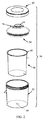
図示を容易にするために、スプレーガン30と収容容器32との間の本開示の接続形体は、図1の図面に含まれない。一般的には、収容容器32は、スプレーガン30への接続のために第1の接続形体を確立する1つ以上の構成要素を含む。収容容器32と入口ポート48との間に組み付けられたアダプタ(図示せず)との、又はスプレーガン30との、相補的な第2の接続形体が含まれる。この背景を念頭において、図2は、本開示の原理による収容容器50の非限定的な一例を示す。収容容器50は、外部容器52及び蓋54を含む。蓋54は、以下により詳細に説明する第1の接続形体又は接続機構56(概略的に参照される)を含むか又は設ける。収容容器50の残された構成要素は様々な形態を取ることができ、任意である。例えば、いくつかの実施形態では、収容容器50は入れ子58とカラー60とを更に含む。一般的には、入れ子58は、容器52の内部と形状が合致し(及びその内部に緊密に嵌合し)、容器52の上縁に着座する開放端において幅の狭いリム62を有することができる。蓋54は、入れ子58の開放端の中に押し込み嵌合されて、蓋54の周縁を入れ子58のリム62の上方に位置付けるように構成される。蓋/入れ子組立体は、容器52を解除可能に係合する環状カラー60(例えば、図示のねじ式接合、スナップ嵌め等)によって適所に固定される。
For ease of illustration, the connection features of the present disclosure between the
接続形体56に加えて、蓋54は、入れ子58によって収容された液体が流れ得る液体出口64(概略的に参照される)を形成する。使用中、入れ子58は、塗料が収容容器50から引き出されるにつれて蓋54の方に軸方向に潰れる。外部容器52の底部の中の任意の通気口66は、入れ子58が潰れるにつれて空気が入ることを可能にする。噴霧終了時に、収容容器50は、スプレーガン30(図1)から外すことができ、カラー60は解除され、蓋/入れ子組立体は一体で外部容器52から取り外される。外部容器52及びカラー60は清浄なまま残され、新しい入れ子58及び蓋54を用いて再使用する準備ができている。このようにして、収容容器50の過剰な洗浄を回避することができる。
In addition to the connecting
他の実施形態では、本開示の収容容器は、入れ子58及び/又はカラー60を含む必要がない。本開示の接続形体は、図面に直接示されるか又は示されない場合がある多くの他の収容容器構成によって実装され得る。
In other embodiments, the containment vessel of the present disclosure need not include
上述のように、蓋54が設けられた第1の接続形体56は、スプレーガン入口又は装置が設けられた相補的な第2の接続形体と解除可能に接続するように構成される。参照の目的で、図3は、蓋54を、通常は第2の相補的接続形体72(概略的に参照される)を担持又は提供するスプレーガン入口70の一部とともに示す。スプレーガン入口70は、アダプタ、スプレーガン30(図1)の一体部分等であり得る。いずれにしても、第1の接続形体56及び第2の接続形体72は縦一列に構成され、蓋54とスプレーガン入口70との間の解除可能で液密封止された取り付け又は接続を促進する。いくつかの実施形態では、第1の相補的接続形体56及び第2の相補的接続形体72は、本開示の原理によるスプレーガン収容容器コネクタシステム74をひとまとめに画定するものと見なされ得る。
As described above, the first connecting
次に、第1の接続形体56が、場合によっては蓋54を分離して示す図4A〜図4Dを参照しながら説明される。蓋54の形状は、長手方向軸Aを画定するものと見なされ得る。第1の接続形体56及び液体出口64に加えて、蓋54は壁80と、フランジ82と、ハブ84とを含むか又は画定する。壁80は、対向する内面86及び外面88を画定し、壁80の少なくとも外面88は、例えば(限定はしないが)図面に示す湾曲した(例えば、半球状の)形状を有する。最終的に、壁80は、長手方向軸Aと同軸である中心開口90(図4Dに最も良く示す)を画定する。フランジ82は、中心開口90の反対側の壁80の外周部から半径方向外向きに突出し、収容容器50(図2)の1つ以上の他の構成要素、例えば外部容器52(図2)と接合するように構成される。ハブ84は、壁80と反対方向にフランジ82から(長手方向軸Aに対して)長手方向に突出し、収容容器50、例えば入れ子58(図2)の1つ以上の他の構成要素と接合するように構成され得る。壁80、フランジ82、及びハブ84は、多様な他の形態を取ることができる。更に、他の実施形態では、フランジ82及びハブ84の一方又は両方を省略することができる。
Next, the
液体出口64は注ぎ口100を含む。注ぎ口100は、長手方向軸Aと同軸であり、壁80から(図4Aの位置付けに対して)上方に突出し、先端表面102において終了する。注ぎ口100は、中心開口90と整合され、中心開口90に対して開いている通路104(図4Dに最も良く示す)を画定する。この構成によれば、(例えば、壁80の内面86の範囲内のあるロケーションから注ぎ口100の外のあるロケーションまで)液体出口64を通る液体の流れは、中心開口90及び通路104を通って容易に発生する。
The
いくつかの実施形態では、液体出口64は、第1の接続形体56の構成要素と任意に見なされ得る1つ以上の追加の機構を含む。例えば、先端表面102は、蓋54へ組み付けられると、相補的構成要素又はデバイス(例えば、図3のスプレーガン入口70)と面封止部を形成するように構成され得る。封止関係は、長手方向軸Aに垂直な平面内の実質的に平らな又は平坦な(すなわち、真に平らな又は平坦な形状の5%以内)先端表面102によって確立され得る。更に、1つ以上の環状リブ106が、注ぎ口100の外側に沿って先端表面102の近傍に形成され得、蓋54へ組み付けられると、スプレーガン入口70との環状封止部を形成するように構成され得る。代替的に、蓋54とスプレーガン入口70との間の液密封止は、先端表面102及び環状リブ106の一方又は両方含むか又は含まない場合がある多様な他の構成によって促進され得る。
In some embodiments, the
第1の接続形体56は、プラットフォーム110と複数の保持構造体112とを含む。プラットフォーム110及び保持構造体112は、注ぎ口100の外のロケーションにおいて壁80の外面88から突出し、以下で説明するように、第2の相補的接続形体72(図3)との選択的接続又は取り付けを容易にするように構成される。
The
プラットフォーム110は、外面88から延びて接触表面120において終了する。接触表面120は、スプレーガン入口(図示せず)との摺動接合をもたらすように構成され、壁80の任意の湾曲形状とは異なる形状を有することができる。いくつかの実施形態では、接触表面120は、長手方向軸Aに垂直な平面内で実質的に平らであるか又は平坦である(すなわち、真に平らな又は平坦な形状の5%以内)。接触表面120は、注ぎ口100を円周方向に取り巻き、保持構造体112のロケーションに対応するように大きさと形状とを決められる。例えば、図4Aに最も良く示すように、接触表面120は、保持構造体112の各々の領域内に拡大された半径方向の幅を有することができる。他の実施形態では、接触表面120は、より均一な半径方向の幅を有することができる。
The
いくつかの実施形態では、保持構造体112は同一であり得る。保持構造体112の各々は、対向する第1の端部124と第2の端部126とを画定し、支持体130とくさび体132とを含む。支持体130は、注ぎ口100から半径方向に間隔を空けられ、壁80から上方に突出する。1つ以上の補強リブ133は、支持体130と壁80との間に任意に設けられ、使用中に支持体130が注ぎ口100から離れるたわみを最小にする役割を果たす。くさび体132は、壁80の反対側に支持体130から半径方向内向きに突出する。捕捉領域134は、スプレーガン入口70の対応する機構を受けるために、接触表面120と、支持体130と、くさび体132とで画定される(図3)。
In some embodiments, the
より具体的には、図4Eに最も良く示すように、支持体130の突出部は案内表面136を画定する。案内表面136は注ぎ口100に面し、注ぎ口100の外側から半径方向の間隔Rだけ半径方向に間隔を空けられる。くさび体132は、案内表面136に対して半径方向内向きに突出し、係合表面138と整合表面140とを画定する。係合表面138は接触表面120に面し、接触表面120から長手方向間隔Lだけ長手方向に間隔を空けられる。接触表面120、案内表面136及び係合表面138が結合して捕捉領域134を画定する。整合表面140は注ぎ口100に面し、注ぎ口100の外側から半径方向の間隙Gだけ半径方向に間隔を空けられる。半径方向の間隔R及び半径方向の間隙Gの寸法は、スプレーガン入口70の幾何学的機構に対応する(図3)。これに関連して、更に図4Dを参照すると、案内表面136は、長手方向軸Aに対して、捕捉直径D1をひとまとめに画定し、整合表面140は、隙間直径D2をひとまとめに画定する。捕捉直径D1及び隙間直径D2は、以下に説明するように、所望の結合及び結合解除動作を容易にするためにスプレーガン入口70の幾何学的機構に従って選択される(その逆も同様)。
More specifically, as best shown in FIG. 4E, the protrusions of the
接触表面120及び係合表面138の幾何学的配置は、捕捉領域134内で相補的な第2の接続形体72(図3)の対応する機構のくさび状係合が容易になるように構成される。図4Fを参照すると、係合表面138は実質的に平らであり(すなわち、真に平らな形状の5%以内)、係合表面138の平面は、接触表面120の平面に対して非平行である。例えば、接触表面120及び係合表面138の平面が結合して1〜70度程度、例えば1〜30度の範囲内の狭角を画定する。この構成によれば、長手方向間隔Lは、第1の端部124から第2の端部126まで先細りになる。この先細りの又はくさび状の形状によって、最初に第1の端部124において捕捉領域134内に挿入され、次いで第2の端部126に向けて案内される固い本体(第2の接続形体72が設けられる)は、以下で説明するように、捕捉領域134内で摩擦によってくさび留めされるか又は係合されることになる。図4Bを更に参照すると、各保持構造体112の捕捉領域134の先細り形状が、長手方向軸Aに対して同じ回転方向にあるように、保持構造体112が配置される。例えば、図4Bの位置付けに対して、保持構造体112の各々の捕捉領域134(図4Bでは隠れている)は、時計回り方向に先細りになる(例えば、第1の端部124は、時計回り方向において対応する第2の端部126の、回転方向において「前方に」ある)。図4Bは、最初に本体を捕捉領域134内に案内することを更に促進するために、先端部124が凹部を画定し得ることを更に示す。各保持構造体112の整合表面140は、図示のように実質的に平坦であり、概ね注ぎ口100の外周に対して接面であり得、他の実施形態では、整合表面140は、弓形形状を有し、注ぎ口100の湾曲を概ね追従することができる。
The geometric arrangement of the
再び図4A〜図4Dを参照すると、保持構造体112は、相補的な第2の接続形体72との堅固な係合又は接続を確立し(図3)、注ぎ口100から離れている。この構成によれば、塗料スプレーガンとともに利用される従来の流体コネクタ設計と異なり、本開示の接続形体は、注ぎ口100及びしたがって液体出口64が比較的大きい内径を提示することを可能にする。いくつかの実施形態では、注ぎ口100の内径は20mm以上であり、代替的に22mm以上であり、任意に、30mm程度である。更に、捕捉領域134を壁80に密接して位置付けることによって、注ぎ口100の高さは、従来のスプレーガン収容容器コネクタ設計と比較して低減され得る。いくつかの非限定的な実施形態では、例えば、注ぎ口100の高さは5〜15mm程度である。
With reference to FIGS. 4A-4D again, the retaining
図4A〜図4Dは、保持構造体112のうちの2つを含むように第1の接続形体56を示すが、他の実施形態では、保持構造体112のうちの3つ以上が設けられる。いくつかの実施形態では、保持構造体112は、注ぎ口100周りに任意に等距離に間隔を空けられる。いずれにしても、開区域150は、保持構造体112のうちの円周方向に隣接する保持構造体112同士の間で画定される。例えば、図4Bは、円周方向に第1の保持構造体112aの第2の端部126と第2の保持構造体112bの第1の端部124との間に第1の開区域150aを識別し、円周方向に第2の保持構造体112bの第2の端部126と第1の保持構造体112aの第1の端部124との間に第2の開区域150bを識別する。
4A-4D show the
再び図3を参照すると、第2の接続形体72は、第1の接続形体56の機構と選択的に対になるように構成される。いくつかの実施形態では、第2の接続形体72は、図5A〜図5Eに示すアダプタ180などのアダプタの一部として設けられる。第2の接続形体72(図5Aに概略的に参照される)に加えて、アダプタ180は管状部材190を含む。様々な構成要素の詳細が以下で与えられる。一般的には、アダプタ180の形状は中心軸Xを画定する。管状部材190は、スプレーガンの入口ポートへの接続を確立するためなど、従来のスプレーガン収容容器接続アダプタに類似の機構を含むか又は設けることができる。第2の接続形体72の底部192は、管状部材190から突出し、第2の接続形体72の他の部分を担持又は画定し、アダプタ180の蓋54への取り付けを促進する(図3)。
With reference to FIG. 3 again, the
管状部材190は様々な形態を取ることができ、中心通路200(図5Eに最も良く示す)を画定する。通路200は、管状部材190の先端部202において開口している。管状部材190は、従来の(例えば、ねじ式)スプレーガン入口ポートへの組み付けを容易にする取り付け機構を形成するか又は設ける。例えば、外部ねじ204は、先端部202に隣接して管状部材190に沿って設けられ、スプレーガン入口ポートによって設けられたねじとねじ止め接合するように構成され得る。これに関連して、外部ねじ204のピッチ、プロファイル、及び間隔は、アダプタ180が使用を意図されるスプレーガンの型/モデルにおける特定のねじパターンに従って選択され得る。外部ねじ202を含んでも含まなくてもよく、又は必要としてもしなくてもよい他のスプレーガン取り付け機構は、等しく容認可能である。管状部材190は、任意で、把持部206を更に含むか又は画定することができる。把持部206は、従来の工具でアダプタ180のユーザ操作を容易にするように構成され、いくつかの実施形態では、レンチによって容易に係合するように適応された六角形表面パターンを含むか又は画定する。他の実施形態では、把持部206を省略することができる。
The
底部192は、先端部202の反対側の管状部材190から延び、肩部210及びリング212を含む。図5Eに最も良く示すように、肩部210及びリング212が結合して、管状部材190の中心通路200に対して開いており、蓋54(図4A)の注ぎ口100(図4A)を受けるように構成されたチャンバ214を画定する。肩部210は、(中心軸Xに対して)管状部材190から半径方向外向きに延び、内側半径面216を画定する。いくつかの実施形態では、内側半径面216は、以下で明らかになる理由のために、中心軸Xに垂直な平面内で実質的に平ら又は平坦(すなわち、真に平らな又は平坦な形状の5%以内)である。リング212は、管状部材190と反対の方向に肩部210の外周部から長手方向に突出し、接触面218において終了する。更に、リング212は、円筒形内面220及び円筒形外面222を画定する。リング212の内径(例えば、円筒形内面220によって画定される直径)は、注ぎ口100の外径に対応する(例えば、近似するか又は外径よりわずかに大きい)。リング212の外径は、接触面218の延長部内に拡大し得るか又は均一であり得る。いずれにしても、リング212の最大外径(例えば、円筒形外面222によって画定される最大直径)は、上記で説明した隙間直径D1(図4D)に対応する(例えば、近似するか又は隙間直径よりわずかに小さい)。いくつかの実施形態では、接触面218は、以下で明らかになる理由のために、中心軸Xに垂直な平面内で実質的に平ら又は平坦(すなわち、真に平らな又は平坦な形状の5%以内)である。
The bottom 192 extends from the
いくつかの実施形態では、内側半径面216及び/又は円筒形内面220は、最終組み付け時に蓋54(図4A)との液密封止を確立し、したがって、本開示の原理による第2の接続形体72の構成要素であると見なされ得る。他の実施形態では、内側半径面216、円筒形内面220、及び/又は底部192の他の構成要素は、第2の接続形体72と分離していると見なされ得る。いずれにしても、第2の接続形体72は、複数の係止構造体230を含む。係止構造体230は、円筒形外面222から外向きに突出し、以下で説明するように、保持構造体112(図4A)のうちの対応する保持構造体と選択的に係合するように大きさと形状とを決められる。
In some embodiments, the inner
いくつかの実施形態では、係止構造体230は同一であり、各々は、リング212に沿って円周方向に拡張して第2の端部242の反対側に第1の端部240を画定する。係止構造体230は、当接面252、係止面254、及び案内面256を画定するシム体又はくさび体250を含む。当接面252は、接触面218において又は接触面218にすぐ隣接してリング212から突出する。いくつかの実施形態では、当接面252は、中心軸Xに垂直な平面内で実質的に平ら又は平坦(すなわち、真に平らな又は平坦な形状の5%以内)であり、接触面218と同一平面である(例えば、接触面218及び当接面252は同一平面上にあり得る)。
In some embodiments, the locking
係止面254は、図5Dで分かるように、シム体250の高さHSを画定するために当接面252の反対側に長手方向に形成される。更に、係止面254は、らせん体の区分に類似するリング212に対する形状又は幾何学的配置を生成する。図5Dに最も良く示すように、当接面252は、実質的に平ら(すなわち、真に平らな形状の5%以内)であり、係止面254の平面は、当接面252の平面に対して非平行である。例えば、当接面252及び係止面254の平面が結合して1〜70度程度、例えば1〜30度の範囲内の狭角を画定する。いくつかの実施形態では、当接面252及び係止面254によって画定される狭角は、使用中に2つの構成要素同士の間に干渉を任意で生み出すために、図4Fに関して以前に説明したように保持構造体112によって画定される狭角とわずかに異なる。この構成によれば、シム体250の高さHSは、以下で明らかになるように、第1の端部240から第2の端部242に向かって増大し、保持構造体112の長手方向間隔L(図4F)に従って選択される。一般的には、この拡大する高さ又はくさび状の形状及び対応する寸法によって、シム体250は、保持構造体112のうちの対応する1つの中で摩擦によってくさび留めされるか又は係合されることになる。いくつかの実施形態では、干渉は、構成要素同士が増大する摩擦及び保持力をもたらすために互いに「食い込む」ように、係止面と保持構造体との相互作用によって生み出される。そのような場合、上述の狭角は、意図的に不整合にされ得る。引き続き図5A〜図5Eを参照すると、各々の係止構造体230のシム体250の拡大する形状が中心軸Xに対して同じ回転方向にあるように、係止構造体230はリング212周りに配置される。例えば、図5Bの位置付けに対して、係止構造体230の各々のシム体250は、時計回り方向に拡大する(例えば、第1の端部240は、時計回り方向において対応する第2の端部242の、回転方向において「前方に」ある)。図5Bは、最初にシム体250を保持構造体112のうちの1つの中に案内することを更に促進するために、第1の端部240が湾曲端部258を画定し得ることを更に示す。
Locking
各々の係止構造体230の案内面256は、リング212の反対側に画定され、いくつかの実施形態では、円筒形外面222の湾曲に倣う。湾曲してもしなくてもよい他の形状もまた、容認可能である。いずれにしても、図5Eで分かるように、案内面256は、最大外径D3を中心軸Xに対してひとまとめに画定する。図4Dを更に参照すると、最大外径D3は、第1の接続形体56の寸法に従って、特に、以下で明らかになる理由のために、捕捉直径D1よりわずかに小さく、かつ隙間直径D2より大きくなるように設計される。
The
いくつかの実施形態では、係止構造体230の各々は、停止体260を更に含み得る。停止体260は、対応する係止構造体230の第2の端部242に位置し、当接面252と反対の方向において対応するシム体250の係止面254から、又は係止面254に対して長手方向に突出する。これに関連して、停止体260は、シム体250の高さHSを越えて突出する停止面262を画定する。図5Dで分かるように、停止体260の高さHBは、以下で明らかになる理由のために、保持構造体112(図4F)の長手方向間隔L(図4F)より大きくなるように選択される。他の実施形態では、停止体260を省略することができる。
In some embodiments, each of the locking
図5A〜図5Eは第2の接続形体72が係止構造体230のうちの2つを含むように示しているが、他の実施形態では、係止構造体230のうちの3つ以上が設けられ、係止構造体230の数は相補的な第1の接続形体56(図4A)が設けられた保持構造体112(図4A)の数と任意に一致する。同様に、係止構造体230の円周方向に隣接する係止構造体230同士の間の間隔は、保持構造体112同士の間の円周方向の間隔に倣う(例えば、いくつかの実施形態では、係止構造体230はリング212 100周りに任意に等距離に間隔を空けられる)。いずれにしても、係止構造体240の各々の円周方向の長さ(例えば、円弧長さ)は、第1の接続形体56の開区域150(図4B)の各々の円周方向の長さより小さい。
5A-5E show that the second connecting
図6を参照すると、第1の接続形体56と第2の接続形体72との間(したがって、蓋54とアダプタ180との間)の係合は、最初にアダプタ180と液体出口64とを整合させることを必然的に伴う。蓋54及びアダプタ180は、アダプタ180の接触面218が蓋54の接触表面120に面し、係止構造体230が保持構造体112から回転方向にオフセットされるように、空間的に配置される(すなわち、係止構造体230はそれぞれ、開区域150のうちのそれぞれの開区域150と長手方向に整合される)。次いで、図7A及び図7Bに示すように、蓋54及びアダプタ180は互いに向けて案内され、アダプタ180の接触面218を、蓋54の接触表面120と接触させる。底部192は注ぎ口100の上方に位置し(図7A及び図7Bでは隠れているが、例えば図6に示されている)、アダプタ180の中心軸Xは、蓋54の長手方向軸Aと整合される。上記の説明と同様に、底部192のリング212の外径は、保持構造体112によってひとまとめに生成された隙間直径D2(図4D)より小さく、底部192を保持構造体112の「内側」の注ぎ口100の上方で入れ子にすることを可能にする。図7A及び図7Bの初期状態では、係止構造体230は、保持構造体112から回転方向に間隔を空けられている。しかしながら、蓋54及びアダプタ180の対応する幾何学的配置によって、接触表面120と接触面218との間の係合は、係止構造体230と保持構造体112とを円周方向に整合させる(例えば、図7Aは、係止構造体230の第1の端部240が、第1の保持構造体112aの捕捉領域134と円周方向に整合されることを示す)。
Referring to FIG. 6, the engagement between the
次いで、アダプタ180は、係止構造体230の各々の第1の端部240を保持構造体112のうちの対応する保持構造体の第1の端部124に向けて移動させる方向に、共通軸A、X周りに蓋54に対して回される(及び/又は、その逆も同様)。例えば、図7Bの位置付けに対して、アダプタ180は、蓋54に対して時計回りに回される。この回転により、係止構造体230の各々のシム体250は、保持構造体112のうちの対応する保持構造体の捕捉領域134の中に案内される。図8A及び図8Bは、保持構造体112と係止構造体230との対応する対の間の初期接合を示す。上記の説明と同様に、図8Bは、係止構造体230が、保持構造体112のうちの対応する保持構造体と接合するために半径方向に位置決めされるように、係止構造体230によってひとまとめに確立された最大外径D3が、保持構造体112によってひとまとめに確立された隙間直径D2より大きいことを強調している。しかしながら、図8Cの断面図に示すように、保持構造体112の案内表面136が対応する係止構造体230の案内面256と明白に接触しないように、そうでなければ蓋54に対するアダプタ180の回転を妨げることがある(及び/又は、その逆も同様)という意味で、最大外径D3は捕捉直径D1より小さい。
The
図8Dの部分的断面図に示すように、係止構造体230の第1の端部240におけるシム体250の高さHS(図5D)は、保持構造体112の第1の端部124における捕捉領域134の長手方向間隔L(図4E)より小さい。したがって、シム体250は、捕捉領域134の中に容易に案内され、接触表面120と係合表面138との間を摺動する。蓋54の接触表面120とアダプタ180の接触面218との間に確立された摺動する平坦な接合は、蓋54に対するアダプタ180の継続的回転(及び/又は、その逆も同様)によってシム体250と捕捉領域134との円周方向の整合を維持する。
As shown in the partial cross-sectional view of FIG. 8D, the
アダプタ180が蓋54に対して更に回される(及び/又は、その逆も同様)(すなわち、図8Dの位置付けに対して、係止構造体230は保持構造体112に対して概ね左方に、更には捕捉領域134の中に移動させられる)ので、捕捉領域134及びシム体250の先細り形状によって、くさび状の結合又は係合が保持構造体112と係止構造体230との間に確立される。シム体250の係止面254は、くさび体132の係合表面138を圧迫する。係止面254と係合表面138との間の(蓋54及びアダプタ180の互いに対する回転による)摺動係合の角度又は平面は、シム体250の当接面252を保持構造体112の接触表面120の方に押し込んで、アダプタ180を蓋54とのより堅固な係合に導く。いくつかの実施形態では、くさび式の係止された係合は、蓋54及びアダプタ180の少なくとも関連する部分を異なる材料で形成することによって更に促進され得る。例えば、いくつかの実施形態では、蓋54がプラスチック材料でアダプタ180が金属(例えば、ステンレス鋼)であり、これら及び同様の構成によって、プラスチックベースの保持構造体112は、より固い金属ベースのシム体250によって力が加えられることに応答してわずかに圧縮又は変形し得、より堅固な係止された接合がもたらされる。
The
蓋54に対するアダプタ180の継続的回転(及び/又は、その逆も同様)によって、各係止構造体230のシム体250は、保持構造体112のうちのそれぞれの保持構造体の捕捉領域134の中で摩擦的及び機械的に係止されることになる。図9A及び図9Bは、係止された状態のアダプタ180及び蓋54を示す。係止構造体230の各々が設けられた任意の停止体260は、アダプタ180の蓋54に対する過剰回転(及び/又は、その逆も同様)を防止する。図9Bに最も良く示すように、停止体260の高さHB(図5D)は、捕捉領域134(概略的に参照される)の長手方向間隔L(図4E)より大きく、停止面262と保持構造体112の第1の端部124との間の当接は更なる回転を防止する。
Due to the continuous rotation of the
係止された状態では、図9Cに示すように、液密封止が維持されている(液密封止は、係止された状態が達成される前に取得され得る、又は取得されることを理解されたい)。特に、注ぎ口100の先端表面102が底部192の内側半径面216に対して接触して封止し、液体出口64の環状リブ106が底部192の円筒形内面220に対して接触して封止する。先端表面102と内側半径面216との間の堅固な液体封止接触は、上記で説明した回転係止動作の一部として、保持構造体112と係止構造体230との間のくさび状の接合によって強化され、内側半径面216は先端表面102と緊密に接触させられる(すなわち、図9Cの位置付けに対して、上記で説明した回転によって、液密封止をより確実にするために、アダプタ180は蓋54に対して下方に押し付けられ、又は引き込まれる(したがって、内側半径面216は先端表面102の上で下方に押し付けられ、又は引き込まれる))。いくつかの実施形態では、液密封止された接合は、蓋54及びアダプタ180の少なくとも関連する部分を異なる材料で形成することによって更に促進され得る。例えば、いくつかの実施形態では、蓋54がプラスチック材料でアダプタ180が金属(例えば、ステンレス鋼)であり、これら及び同様の構成によって、蓋54のプラスチックベースの注ぎ口100及び環状リブ106は、より固い金属ベースの底部192によって力が加えられることに応答してわずかに圧縮又は変形し得、構成要素同士の間により堅固な封止接触がもたらされる。
In the locked state, as shown in FIG. 9C, the liquidtight seal is maintained (understood that the liquidtight seal can or is obtained before the locked state is achieved. I want to be). In particular, the
使用後、係止構造体230を対応する保持構造体112から引き抜くために、アダプタ180を蓋54に対して反対方向(例えば、反時計回り)に回すことによって、アダプタ180が蓋54から解除され得る。係合解除されると、アダプタ180は蓋54から分離され得る。いくつかの実施形態では、保持構造体112と係止構造体230との間の反転カム式接合は、アダプタ180の回転によって発生し得(すなわち、上記の説明の逆における接合)、アダプタ180と蓋54との間の任意の封止を解除するのを支援する役割を果たす。係合解除されると、アダプタ180は蓋54から分離され得る。
After use, the
上記のように、いくつかの実施形態では、蓋54及びアダプタ180は異なる材料で形成され得る。例えば、蓋54はプラスチック構成要素(例えば成形プラスチック)であり得、アダプタ180は金属(例えば、ステンレス鋼)であり得る。これらの任意の構成によって、噴霧動作に続いて、アダプタ180は容易に洗浄及び再使用され得、蓋54は消耗部品と見なされ得る。
As mentioned above, in some embodiments, the
再び図3を参照すると、上記の説明はアダプタ180(図5A)の一部として相補的な第2の接続形体72を提供したが、他の構成も同様に容認可能である。例えば、第2の接続形体72は、スプレーガンに永久に組み付けられ得るか、又はスプレーガンの一体部分として設けられ得る(例えば、上記で説明した第2の接続形体72は、スプレーガン30(図1)の入口ポート48(図1)として又は入口ポート48において設けられ得る)。すなわち、本開示のスプレーガン収容容器コネクタシステムは、アダプタを必要としない。
With reference to FIG. 3 again, the above description provided a complementary
加えて、第1の接続形体56及び第2の接続形体72のロケーションは、反転され得る。次いで、他の実施形態では、第2の接続形体72が蓋54を形成され得るか又は設けられ得、第1の接続形体56がスプレーガン入口70(例えば、アダプタ、スプレーガン入口ポート等)を形成され得るか又は設けられ得る。例えば、図10は、相補的な第1の接続形体302及び相補的な第2の接続形体304を含む代替のスプレーガン収容容器コネクタシステム300の部分を示す(概略的に参照される)。第1の接続形体302は蓋310の一部として設けられ、第2の接続形体304は、図示のアダプタ312など、スプレーガン入口の一部として設けられる。
In addition, the locations of the
蓋310は、上記で説明した蓋54(図2)に類似し得、一般に、壁320と注ぎ口322を含む液体出口とを含む。第1の接続形体302は、注ぎ口322の外側に沿って互いに円周方向に間隔を空けられた複数の係止構造体330を含む。係止構造体330は上記で説明した係止構造体230(図5A)に高度に類似し得、注ぎ口322は底部192(図5A)に機能的に類似する。更に図11に示すように、係止構造体330の各々は、シム体332と任意の停止体334とを含む。シム体332は、シム体250(図5A)に関して上記で説明した機構のいずれかを有し得、全体的に、第1の端部336から第2の端部338に向けて拡大する高さをもたらす。停止体334は第2の端部338に位置し、停止体260(図5A)に関して上記で説明した機構のいずれかを有し得る。
The
再び図10を参照すると、蓋310は、第1の接続形体302の一部と任意に見なされる1つ以上の封止機構を提供し得る。例えば、傾斜面封止部340は、先端部342の近傍の注ぎ口322の内側に沿って形成され得る。追加又は代替として、環状リブ封止部344は、先端部342から間隔を空けられたロケーションにおいて注ぎ口322の内側に沿って形成され得る。他の封止構成も想定され得る。
With reference to FIG. 10 again, the
アダプタ312は、上記で説明したアダプタ180(図5A)に類似し得、一般に、管状部材350を含む。第2の接続形体304は管状部材350から突出し、プラットフォーム352、リング354、及び複数の保持構造体356を含む。プラットフォーム352は環状の形状を有し、管状部材350の外径より大きい外径を画定する。リング354は管状部材350と同軸であり、上記で説明した注ぎ口100(図4A)に機能的に類似すると見なされ得る。リング354が注ぎ口322の中で入れ子になることができるように、リング354の外径は注ぎ口322の内径より小さい。封止機構は、注ぎ口322に対して付加的な封止及び保持力をもたらすために、リング354の外径において設けられ得る。保持構造体356は、上記で説明した保持構造体112(図4A)に高度に類似し得、支持体360及びくさび体362を含む。プラットフォーム352の表面、支持体360及びくさび体362が結合して、くさび式係合においてシム体332のうちの対応する1つを摺動的に受けるように大きさを決められた、上記の説明と同様の捕捉領域364を画定する。
The
リング354は、接続形体に組み込まれた個別の構成要素として設けられ得る。このようにして、従来の製造技法を用いて別の方法で実現できるものより複雑な幾何学的配置が、達成可能となる。
The
アダプタ312を蓋310に結合することは、前の実施形態に高度に類似する方法で達成される。アダプタ312は注ぎ口322と軸方向に整合され、保持構造体356は係止構造体330に対して回転方向にオフセットされる。次いで、アダプタ312は蓋310の上に進められ、リング354が注ぎ口322の中で入れ子になる。次いで、アダプタ312は蓋310に対して回され(及び/又は、その逆も同様)、保持構造体356が係止構造体330のうちのそれぞれの係止構造体と係合させられる。くさび式接合が設けられ、アダプタ312は、上記で説明したように、引き込まれて蓋310と堅固に接触する。さらなる回転によって、係止構造体330の各々のシム体332は、対応する保持構造体356の捕捉領域364の中で摩擦的及び機械的に係止される。設けられた場合、係止構造体330の各々の停止体334は対応する保持構造体356と接触し、アダプタ312の過剰回転を防止する。図12は、蓋310とアダプタ312との間(したがって、相補的な第1の接続形体302と相補的な第2の接続形体304(概略的に参照される)との間)の係止された配置の簡略化された表現である。係止構造体330の各々のシム体332は、対応する保持構造体356の捕捉領域364の中にくさび留めされる。少なくとも1つの液密封止が、注ぎ口322の傾斜面封止部340とアダプタ312のリング354との間の接触接合において提供される。図12の実施形態では、第2の液密封止が、リング354の先端部370と蓋310が設けられた環状リブ封止部372との間の接触接合において提供される。図12の図における環状リブ封止部372のロケーションは、図10の環状リブ封止部342とは異なり、代替の封止手法を示すことが理解されよう。
Coupling the
上記の説明は、アダプタ312の一部として相補的な第2の接続形体304を提供したが、他の構成もまた容認可能である。例えば、第2の接続形体304は、スプレーガンに永久に組み付けられ得るか、又はスプレーガンの一体部分として設けられ得る(例えば、上記で説明した第2の接続形体304は、スプレーガン30(図1)の入口ポート48(図1)として又は入口ポート48において設けられ得る)。
The above description provides a complementary
図13は、本開示の原理による、相補的な第1の接続形体402及び第2の接続形体404(概略的に参照される)を含む代替のスプレーガン収容容器コネクタシステム400の部分を示す。第1の接続形体402は蓋410の一部として設けられ、第2の接続形体404は、スプレーガンへの接続に適応されるように示されるアダプタ412など、スプレーガンの液体入口の一部として設けられる。
FIG. 13 shows a portion of an alternative spray gun containment
蓋410は図14A〜図14Eにより詳細に示され、多くの点で、上記で説明した蓋54(図4A)に高度に類似し得るか又は蓋54と同一であり得る。蓋410は、一般に、壁420と液体出口422とを含む。液体出口422は、注ぎ口424を、注ぎ口424の先端表面426及び/又は先端表面426の近傍の注ぎ口424の外側に沿って形成された1つ以上の環状リブ428など、上記で説明した任意の封止機構とともに含む。設けられた場合、いくつかの実施形態では、封止機構は、第1の接続形体402の構成要素と見なされ得る。
The
第1の接続形体402(図14Aにて概略的に参照される)は、プラットフォーム440と複数の保持構造体442とを含む。保持構造体442は、上記で説明した保持構造体112(図4A)に高度に類似し得、注ぎ口424から半径方向に間隔を空けられたロケーションにおいて互いに円周方向に間隔を空けられる。一般的には、保持構造体442の各々は、床444と、支持体446と、くさび体448とを含む。床444は、保持構造体442の領域(図14Eの断面図に最も良く示す)内に、プラットフォーム440の表面と概ね整合される接触表面450を画定する。支持体446は床444から突出し、案内表面452を画定する(図14B)。くさび体448は、床444の反対側の支持体446から半径方向内向きに延び、図14Eに最も良く示す係合表面454を画定する。表面450〜454が結合して、図14Eに示す先細り形状又は傾斜形状を有する捕捉領域456を画定する。例えば、図14Eの位置付けに対して、捕捉領域456の形状は、第1の端部458と第2の端部459との間の延長部内に垂直下向きの構成要素を有する。言い換えれば、捕捉領域456の形状は、捕捉領域456が注ぎ口424周りに回転するときのらせん体の区分に類似し得る。他の形状又は構成もまた想定される。更に他の実施形態では、保持構造体442のうちの3つ以上が設けられ得る。
The first connection form 402 (scheduled in reference in FIG. 14A) includes a
プラットフォーム440は上記で説明したプラットフォーム110(図4A)に機能的に類似し、傾斜表面460を画定する。上記で説明した他の実施形態とは対照的に、プラットフォーム440は、傾斜表面460が注ぎ口424周りに変化する形状を有するように構成される。特に、図14B〜図14Dに最も良く示すように、複数のアンダーカット部462がプラットフォーム440内に画定され、複数の傾斜区分464を生成する。傾斜区分464の各々に沿った傾斜表面460は部分らせん形状を有し、傾斜区分464が注ぎ口424周りに回転するにつれて長手方向に移行する。例えば、第1の傾斜区分464aは図14B〜図14Dにおいて識別され、第1のアンダーカット部462aと第2のアンダーカット部462bとの間で画定される。第1の傾斜区分464aは、第1の保持構造体442aに対応するように位置する。これらの規則を念頭に置いて、第1の傾斜区分464aの傾斜表面460は、第1のアンダーカット部462aから第2のアンダーカット部462bまで長手方向下向きに先細りになる。図14Bの直立の向きに対して、第1の傾斜区分464aの傾斜表面460は、第1のアンダーカット部462aのロケーションにおいて第1の保持構造体442aの床444の垂直方向「上方」にあり、第1の保持構造体442aの領域内で床444と垂直方向に整合され、第2のアンダーカット部462bのロケーションにおいて床の垂直方向「下方」にある。肩部466(図14B)は、以下で明らかになる理由のために、アンダーカット部462の各々において画定される。図14Dに最も良く示すように、少なくとも1つのアンダーカット部462が、保持構造体442のうちの円周方向に隣接する保持構造体442同士の間に形成され、いくつかの実施形態では、アンダーカット部462のうちの単一のアンダーカット部が、一対の保持構造体442の間の円周方向の中点に位置する。関連する実施形態では、アンダーカット部462の数(したがって、傾斜区分464の数)は、保持構造体442の数と一致する。
再び図13を参照すると、アダプタ412は、上記で説明したアダプタ180(図5A)に高度に類似し得、一般に、管状部材480を含む。管状部材480は、管状部材190(図5A)に関して上記で説明した機構のいずれかを含み得る。第2の接続形体404は、底部500と複数の係止構造体502とを含む。底部500は、管状部材480から突出し、係止構造体502を担持する。以下で説明するように、係止構造体502は、次に、保持構造体442のうちの対応する保持構造体と選択的に接合するように構成される。
With reference to FIG. 13 again, the
アダプタ412は、図15A〜図15Dにおいてより詳細に示される。底部500は、肩部510とリング512とを含む。図15Dに最も良く示すように、肩部510及びリング512が結合して、管状部材480の通路に対して開いており、蓋410(図14A)の注ぎ口424(図14A)を受けるように構成されたチャンバ514を画定する。肩部510は、管状部材480から半径方向外向き及び下向きに延びて、内面516を画定する。リング512は、管状部材480と反対の方向に肩部510の外周部から長手方向に突出し、接触面518において終了する。更に、リング512は、円筒形内面520及び円筒形外面522を画定する。リング512の内径(例えば、円筒形内面520によって画定される直径)は、注ぎ口424の外径に対応する(例えば、近似するか又は外径よりわずかに大きい)。リング512の外径は、接触面518の延長部内に拡大し得るか又は均一であり得る。いずれにしても、リング512の最大外径(例えば、円筒形外面522によって画定される最大直径)は、前の説明と同様に、保持構造体442(図14A)によってひとまとめに確立される隙間直径内で入れ子にするように選定される。
The
接触面518の形状の幾何学的配置は、傾斜表面460(図14A)に関して上記で説明したものと同様である。特に、複数のアンダーカット部530が接触面518に沿って形成され、複数の軌道区分532を生成する。接触面518内のアンダーカット部530の数、円周方向のロケーション、及び形状は、上記で説明したプラットフォーム440(図14A)内のアンダーカット部462(図14B〜図14D)に対応する。軌道区分532の各々に沿った接触面518は、部分らせん形状を生成し、アンダーカット部530の各々においてタブ534を形成する。
The geometric arrangement of the shape of the
いくつかの実施形態では、係止構造体502は同一であり、各々は、図15Bに最も良く示すように、リング512に沿って円周方向に拡張して第2の端部542の反対側に第1の端部540を画定する。係止構造体502は、上記で説明した係止構造体230(図5A)に類似し得、当接面552、係止面554、及び案内面556を画定するシム体又はくさび体550を含む。当接面552は、接触面518において又はすぐ隣接してリング512から突出する。いくつかの実施形態では、当接面552の形状は、接触面518の対応する形状に適合し、したがって、(例えば、らせん体の区分に類似する)傾斜した向きを有し得る。
In some embodiments, the locking
係止面554は、シム体550の高さを画定するために当接面552の反対側に長手方向に形成される。いくつかの実施形態では、係止面552の平面は、当接面552の平面と実質的に平行であり、したがって、図15Bの図に最も良く示すらせん体の区分に類似するリング512に対する形状又は幾何学的配置を生成する。この構成によれば、リング512に対するシム体550の垂直ロケーションは、シム体550がリング512周りに回転するにつれて変化し、第1の端部540は、図15A〜図15Dの直立の向きに対して第2の端部542の垂直方向「下方」にある。各係止構造体502のシム体550の角度の向きが、中心軸Xに対して同じ回転方向にあるように、係止構造体502がリング512周りに配置される。例えば、図15Bの位置付けに対して、係止構造体520の各々のシム体550は、時計回り方向に下向きに延びる(例えば、垂直方向により低い第1の端部540は、時計回り方向において対応する垂直方向により高い第2の端部542の、回転方向において「前方に」ある)。
The locking
アダプタ412が設けられた係止構造体502の数は、蓋410(図14A)が設けられた保持構造体442(図14A)の数に一致する。したがって、係止構造体502のうちの3つ以上が、他の実施形態とともに含まれ得る。他の場所で説明された係止構造体230(図5A)とは対照的に、係止構造体502は停止体を含む必要はない。
The number of locking
再び図13を参照すると、蓋410とアダプタ412との結合は、前の説明と同様である。まず、リング512が注ぎ口424と整合される。図13の配置では、アダプタ412は、係止構造体502が保持構造体442から回転方向にオフセットされるように、回転方向に配置される。次いで、アダプタ412は蓋410の上に案内され(及び/又は、その逆も同様)、注ぎ口424が底部500の中で入れ子になる。
Referring again to FIG. 13, the coupling between the
図16A及び図16Bの初期の組み付け状態では、上記で説明したようにアダプタ412は蓋410上に置かれており、係止構造体502は保持構造体442から回転方向に間隔を空けられる。アダプタ412の接触面518は、蓋のプラットフォーム440の傾斜表面460を圧迫している。上記で説明した、蓋410の傾斜区分464に沿った傾斜表面460と、アダプタ412の軌道区分532に沿った接触面518との部分らせん形状によって、係止構造体502は、(図16A及び図16Bの位置付けに対して)保持構造体442の各々の捕捉領域456の垂直方向「上方」に位置する。
In the initial assembled state of FIGS. 16A and 16B, the
次いで、アダプタ412は蓋410に対して回され(及び/又は、その逆も同様)、係止構造体502の各々を保持構造体442のうちの対応する保持構造体との係合が導かれる。例えば、図16A及び図16Bにおいて識別される第1の保持構造体442a及び第1の係止構造体502aを参照すると、アダプタ412は、シム体550の第1の端部540が、第1の保持構造体442aの第1の端部458における捕捉領域456に接近し、次いで入るように、(例えば、時計回りに)回され得る。傾斜表面460と接触面518との間の摺動接合及び対応するらせん状の形状によって、アダプタ412が回されるのにつれて、アダプタ412が保持構造体442に対して垂直に低下するか又は低くなり、それにより、第1の係止構造体502aが第1の保持構造体442aの第1の端部458に近づくにつれて、第1の係止構造体502aの第1の端部540は、第1の保持構造体442aの第1の端部458における捕捉領域456と整合するようになる。
The
蓋410に対するアダプタ412の継続的回転(及び/又は、その逆も同様)によって、各係止構造体502のシム体550は、保持構造体442のうちのそれぞれの保持構造体の捕捉領域456の中で摩擦的及び機械的に係止されることになる。図17A及び図17Bは、蓋410及びアダプタ412が係止された状態を示す。アダプタ412の接触面518は、傾斜表面460に対して及びそれに沿って更に回転し、より完全な係止構造体502の係合を保持構造体442の中に達成する。各軌道区分532のタブ534(そのうちの1つが図17Aに見られる)と肩部466(そのうちの1つが図17Aに見られる)との間の当接接合は、蓋410に対するアダプタ412の過剰回転(及び/又は、その逆も同様)を防止し、接続組み付けを安定にする役割を果たす。図17Cの断面図は、保持構造体442のうちの1つの捕捉領域456(概略的に参照される)内に格納されたくさび体550のうちの1つを示し、くさび体550の形状及び空間的な向きは、捕捉領域456の形状及び空間的な向きに倣うことを示す。係止された状態では、シム体550の当接面552は床444の接触表面450を圧迫し、シム体550の係止面554はくさび体448の係合表面454を圧迫する。回転軸に垂直な平面に対する接触表面450及び係合表面454並びに当接面552及び係止面554の下向きの角度の向きは、シム体550が捕捉領域456を通って漸次進む(すなわち、シム体550の第1の端部540が保持構造体442の第1の端部458から第2の端部459まで漸次進む)につれて、アダプタ412が、蓋410の上に(図17Cの位置付けに対して)下方に引っ張られるか又は引き込まれ、構成要素同士の間の液密封止が促進されることを決定付ける。他の封止機構は、上記の他の実施形態と同様に設けられ得る。
Due to the continuous rotation of the
上記の説明は相補的な第2の接続形体404(図13に概略的に参照される)をアダプタ412の一部として提供したが、他の構成も容認可能である。例えば、第2の接続形体404は、スプレーガンに永久に組み付けられ得るか、又はスプレーガンの一体部分として設けられ得る(例えば、上記で説明した第2の接続形体404は、スプレーガン30(図1)の入口ポート48(図1)として又は入口ポート48において設けられ得る)。加えて、第1の接続形体402及び第2の接続形体404のロケーションは、反転され得る。他の実施形態では、次いで、第2の接続形体404は蓋410を形成され得るか又は設けられ得、第1の接続形体402はスプレーガン入口(例えば、アダプタ、一体型スプレーガン入口ポート等)を形成され得るか又は設けられ得る。
Although the above description provides a complementary second connection form 404 (schematically referenced in FIG. 13) as part of the
上記で説明した傾斜表面460によってもたらされる先細りの又は傾斜式接合は、本開示の原理による他の幾何学的配置又は設計を用いて達成され得る。例えば、本開示の原理による別の蓋580の部分が、図18A〜図18Dに示されている。蓋580は、本開示で説明された蓋のいずれかに類似し、プラットフォーム582を含む。理解を容易にするために、上記で説明した接続形体の機構は、図18A〜図18Dの図から省略されている。第1のアンダーカット部584a及び第2のアンダーカット部584bは、上記の説明と同様に、プラットフォーム582の面586に沿って形成される。面586は注ぎ口588周りに回転し、注ぎ口588に沿って回転方向が指定され得る(例えば、時計回り又は反時計回り)。時計回り方向に対して、面586の第1の部分590aは、第1のアンダーカット部584aから第2のアンダーカット部584bまで円周方向に延びるように見られ得、第2の部分590bは、第2のアンダーカット部584bから第1のアンダーカット部584aまで円周方向に延びるように見られ得る。部分590a、590bの各々は、平らな区分592と傾斜区分594とを含む。傾斜区分594は上記で説明した傾斜表面460(図14A)に類似する一方で、平らな区分592は実質的に平坦である(例えば、傾斜区分594の平面は平らな区分592の平面に対して傾いている)。この構成によれば、上記で説明した先細りの又は傾斜式接合が提供され得、蓋580は、成形による製造の容易さを促進するように設計される。
The tapered or inclined joints provided by the
本開示に記載の相補的接続形体のいずれかは、対応する蓋の残りの部分と一体に形成され得る。代替的に、これらの構成要素は、最初に、個別のモジュール部品として、又は蓋の残りの部分への接続を可能にする接続形状を含む組立体として形成され得る。例えば、モジュール式蓋組立体600が図19に示されており、モジュール式液体出口602及びモジュール式蓋底部604を含む。モジュール式構成要素602、604は個別に形成され、その後組み付けられる。一般的には、モジュール式液体出口602は、ステージ610、液体出口612、及び接続形体614の構成要素(概略的に参照される)を含む。ステージ610は、以下で説明するモジュール式蓋底部604の対応する機構に従って大きさ及び形状を決められ、液体出口612と接続形体614とを支持する。液体出口612及び接続形体614は、上記で説明した形態のいずれかを取ることができ、図19の非限定的な例では、上記で説明した液体出口64(図4A)及び第1の接続形体56(図4A)であり得る。本明細書で説明する任意の他の接続形体は、代替的に、モジュール式液体出口602の中に組み込まれ得る。
Any of the complementary connecting features described in the present disclosure may be formed integrally with the rest of the corresponding lid. Alternatively, these components may first be formed as separate modular components or as an assembly containing a connection shape that allows connection to the rest of the lid. For example, the
モジュール式蓋底部604は、一般に、壁620と、壁620から突出するリム622とを含む。壁620は中心開口624を形成し、ステージ610の大きさ及び形状に従って大きさ及び形状を決められる。中心開口624は様々な形状及び大きさを取ることができるが、開口624の外径は、一般に、液体出口612の内径より大きく、ステージ610の外径より小さいように構成される。
The
モジュール式蓋組立体600の組み付けは、中心開口624が液体出口612に対して開きながら、ステージ610を壁620の上に固定することを含む。モジュール式液体出口602は、いくつかの実施形態では、溶接及び/又は接着剤等によってモジュール式蓋底部604に固定される。いくつかの実施形態では、接着継手及び/又は溶接継手は、モジュール式液体出口602をモジュール式蓋底部604に組み付ける際に、液密封止を維持しかつ生み出すように作用する。4分の1ターンロック、機械的係止機構の用具、ねじ式、スナップ嵌め、他のメカニカルファスナー(例えば、構成要素を適所に保持/維持して適切な漏れ止め封止を施す、ねじ、鋲及び/又は冷間/熱間成形された、キノコ頭を押し込む成形ポスト)など、他の取り付け技法はまた、容認可能である。
Assembling the
モジュール式液体出口602及びモジュール式蓋底部604を使用して蓋600を構成することにより、別の方法で、例えば射出成形を用いてなし得るよりも複雑な形状を都合良く生み出すことができるという利点がもたらされ得る。例えば、所与の蓋600において、いくつかの機構を形成するために必要な金型分割線のロケーション及びスライドの必要な軌道によって、特定の形状を射出成形品内に形成することが不可能な場合がある。しかしながら、蓋600がモジュール式構成要素に分割されるならば、一体型の蓋に対して到達できなかったはずのモジュール式構成要素の各々の表面に直接到達するための工程が、設計され得る。したがって、さらなる幾何学的複雑さが達成され得る。
The advantage of constructing the
モジュール式蓋構成要素602、604はまた、用途に望ましいように異なる材料で構成されてもよい。例えば、モジュール式液体出口602に対してエンプラを使用することが望ましい場合がある(スプレーガンに対する確実で耐久性のある接続に必要な強度及び許容値による)一方で、より低コストのポリマーは、モジュール式蓋底部604に使用され得る。
他の実施形態では、上記のように提供されるモジュール式液出口602は、代替的に、塗料供給管路又はポーチ等の端部に取り付けられるか又は予め組み付けられ、次にスプレーガン塗料入口ポートに接続され得る。このようにして、塗料は、モジュール式蓋底部504(又は他の収容容器構成要素)を必要とすることなく、スプレーガンに直接供給され得る。
In other embodiments, the modular
本開示のスプレーガン収容容器コネクタシステムは、以前の設計に勝る顕著な改善をもたらす。接続形体の様々な構成要素を、蓋によって形成される液体出口(又は注ぎ口)の外側に又は液体出口(又は注ぎ口)から離れて位置付けることによって、注ぎ口の内径が、従来の設計と比較して増加され得る。これは、ひいては、注ぎ口を通る流量を改善し得る。更に、本開示のコネクタシステムは、従来の設計と比較すると、スプレーガンに対する収容容器の重心を下げる。また、より安定で堅固な接続がもたらされ、噴霧動作中にスプレーガンに対して収容容器に起こり得る「ふらつき」を最小にする。 The spray gun containment container connector system of the present disclosure provides significant improvements over previous designs. By locating the various components of the connecting form outside the liquid outlet (or spout) formed by the lid or away from the liquid outlet (or spout), the inner diameter of the spout is compared to conventional designs. Can be increased. This in turn can improve the flow rate through the spout. In addition, the connector system of the present disclosure lowers the center of gravity of the containment vessel relative to the spray gun as compared to conventional designs. It also provides a more stable and robust connection, minimizing the "wobble" that can occur in the containment vessel against the spray gun during the spraying operation.
好ましい実施形態を参照しながら本開示を説明してきたが、本開示の趣旨及び範囲から逸脱することなく形態及び細部の変更を行えることは、当業者には理解されよう。 Although the present disclosure has been described with reference to preferred embodiments, it will be appreciated by those skilled in the art that modifications of form and detail can be made without departing from the spirit and scope of the present disclosure.
Claims (12)
前記注ぎ口の外側に半径方向に間隔を空けられた第1の接続形体とを含み、前記第1の接続形体が、
前記注ぎ口の周りに沿って延在する面を含み、前記面が、第1の平らな区分及び第1の傾斜区分に沿って第2のアンダーカット部まで前記注ぎ口の周りにおいて円周方向に延びる第1の部分を含み、前記第1の部分は、第1のアンダーカット部から前記第2のアンダーカット部まで円周方向に延びる、スプレーガン収容容器構成要素。 With a liquid outlet including a spout,
The first connecting form includes a first connecting form that is radially spaced outside the spout, and the first connecting form is:
Includes a surface that extends along the circumference of the front Symbol spout, said surface, the circumference at around the spout to a second undercut portions along the first flat section and the first inclined segment A spray gun containing container component that includes a first portion extending in the direction, the first portion extending in the circumferential direction from the first undercut portion to the second undercut portion.
Priority Applications (1)
| Application Number | Priority Date | Filing Date | Title |
|---|---|---|---|
| JP2021076968A JP7269986B2 (en) | 2016-01-15 | 2021-04-30 | Wide mouth fluid connector for handheld spray guns |
Applications Claiming Priority (3)
| Application Number | Priority Date | Filing Date | Title |
|---|---|---|---|
| US201662279619P | 2016-01-15 | 2016-01-15 | |
| US62/279,619 | 2016-01-15 | ||
| PCT/US2017/013127 WO2017123714A1 (en) | 2016-01-15 | 2017-01-12 | Wide-mouthed fluid connector for hand-held spray guns |
Related Child Applications (1)
| Application Number | Title | Priority Date | Filing Date |
|---|---|---|---|
| JP2021076968A Division JP7269986B2 (en) | 2016-01-15 | 2021-04-30 | Wide mouth fluid connector for handheld spray guns |
Publications (3)
| Publication Number | Publication Date |
|---|---|
| JP2019504754A JP2019504754A (en) | 2019-02-21 |
| JP2019504754A5 JP2019504754A5 (en) | 2020-02-20 |
| JP6880042B2 true JP6880042B2 (en) | 2021-06-02 |
Family
ID=57915110
Family Applications (2)
| Application Number | Title | Priority Date | Filing Date |
|---|---|---|---|
| JP2018536850A Active JP6880042B2 (en) | 2016-01-15 | 2017-01-12 | Wide-mouth fluid connector for handheld spray gun |
| JP2021076968A Active JP7269986B2 (en) | 2016-01-15 | 2021-04-30 | Wide mouth fluid connector for handheld spray guns |
Family Applications After (1)
| Application Number | Title | Priority Date | Filing Date |
|---|---|---|---|
| JP2021076968A Active JP7269986B2 (en) | 2016-01-15 | 2021-04-30 | Wide mouth fluid connector for handheld spray guns |
Country Status (9)
| Country | Link |
|---|---|
| US (1) | US10688511B2 (en) |
| EP (3) | EP3845313B1 (en) |
| JP (2) | JP6880042B2 (en) |
| CN (1) | CN108778522A (en) |
| AU (1) | AU2017207357B2 (en) |
| CA (1) | CA3011441C (en) |
| ES (1) | ES2866107T3 (en) |
| PL (1) | PL3402604T3 (en) |
| WO (1) | WO2017123714A1 (en) |
Families Citing this family (24)
| Publication number | Priority date | Publication date | Assignee | Title |
|---|---|---|---|---|
| US10857553B2 (en) | 2013-12-05 | 2020-12-08 | 3M Innovative Properties Company | Container for a spraying device |
| CA2991762A1 (en) | 2015-07-08 | 2017-01-12 | 3M Innovative Properties Company | Spray gun cups, receptacles, and methods of use |
| PL3402604T3 (en) * | 2016-01-15 | 2021-07-19 | 3M Innovative Properties Company | Wide-mouthed fluid connector for hand-held spray guns |
| CA3011437C (en) | 2016-01-15 | 2024-02-13 | 3M Innovative Properties Company | Spray gun cups, receptacles, lids, and methods of use |
| US10689165B2 (en) | 2016-01-15 | 2020-06-23 | 3M Innovative Properties Company | Reservoir systems for hand-held spray guns and methods of use |
| CA3011425A1 (en) | 2016-01-15 | 2017-07-20 | 3M Innovative Properties Company | Modular spray gun lid assemblies and methods of design and use |
| CA3011435A1 (en) | 2016-01-15 | 2017-07-20 | 3M Innovative Properties Company | Spray gun cups, receptacles, and methods of use |
| CN108472669B (en) | 2016-01-15 | 2021-10-01 | 3M创新有限公司 | Connector system for a hand-held spray gun |
| EP3551341B1 (en) | 2016-12-06 | 2023-02-22 | 3M Innovative Properties Company | Spray gun and nozzle assembly attachment |
| EP3551338B1 (en) | 2016-12-06 | 2022-11-09 | 3M Innovative Properties Company | Spray gun air cap with retention means |
| US11154894B2 (en) | 2016-12-12 | 2021-10-26 | 3M Innovative Properties Company | Spray gun and nozzle assembly attachment |
| EP3551339B1 (en) * | 2016-12-12 | 2023-06-14 | 3M Innovative Properties Company | Reservoir systems for hand-held spray guns |
| US11666934B2 (en) | 2016-12-12 | 2023-06-06 | 3M Innovative Properties Company | Spray gun and nozzle assembly attachment |
| CN110072631B (en) | 2016-12-12 | 2022-02-01 | 3M创新有限公司 | Spray gun and nozzle assembly attachment |
| US11458491B2 (en) | 2018-12-27 | 2022-10-04 | 3M Innovative Properties Company | Fluid delivery assembly for a spraying apparatus |
| CN210252849U (en) * | 2019-05-05 | 2020-04-07 | 青岛汉柏塑料科技有限公司 | Container sealing cover, screw cap and spray gun container connecting mechanism |
| USD916232S1 (en) * | 2019-06-04 | 2021-04-13 | Qingdao Hanbo Plastic Technology Co., Ltd. | Lid for spray gun |
| USD916231S1 (en) * | 2019-06-04 | 2021-04-13 | Qingdao Hanbo Plastic Technology Co., Ltd. | Lid for spray gun |
| JP1651759S (en) * | 2019-07-04 | 2020-01-27 | ||
| CN110424688B (en) * | 2019-08-17 | 2024-01-02 | 温州瓯厦建设有限公司 | Cement filling gun |
| USD1014702S1 (en) * | 2021-04-14 | 2024-02-13 | 3M Innovative Properties Company | Securement for paint dispensing system |
| WO2023002773A1 (en) | 2021-07-19 | 2023-01-26 | キヤノン株式会社 | Display device, imaging device, and electronic apparatus |
| CN215744212U (en) * | 2021-09-18 | 2022-02-08 | 青岛汉柏塑料科技有限公司 | Switching mechanism for connecting spray gun and supply cup |
| EP4335552A1 (en) * | 2022-09-08 | 2024-03-13 | Fairway Electronic Co., Ltd. | Foam spray can and quick release structure for foam spray can |
Family Cites Families (140)
| Publication number | Priority date | Publication date | Assignee | Title |
|---|---|---|---|---|
| US1395965A (en) | 1919-08-13 | 1921-11-01 | Edward J Mclean | Atomizing and spraying device |
| US1732691A (en) | 1927-04-28 | 1929-10-22 | Vilbiss Co | Spray head |
| US1968173A (en) | 1932-11-28 | 1934-07-31 | Russell Matthew | Spraying device |
| US2004574A (en) | 1933-02-13 | 1935-06-11 | Jr William Oliver Gee | Spray gun reservoir |
| US2037240A (en) | 1933-09-25 | 1936-04-14 | Johnson Swan | Clutch device adapted for spray guns |
| DE890223C (en) | 1951-11-05 | 1953-09-17 | Siemens Ag | Device for preventing premature tripping of tensioning mechanisms, especially in the case of overcurrent triggers |
| US3083883A (en) | 1960-03-30 | 1963-04-02 | Robert T Glidden | Container for spray appliance |
| GB1066861A (en) | 1963-02-22 | 1967-04-26 | Carr Fastener Co Ltd | Clip for fastening together two apertured panels |
| US3381845A (en) | 1967-01-03 | 1968-05-07 | Roderick B. Macdonald | Disposable plastic container for spray guns |
| US3672645A (en) | 1971-01-08 | 1972-06-27 | Joseph L Terrels | Container and stirrer for paint sprayer |
| CA949496A (en) | 1971-07-26 | 1974-06-18 | Anchor Cap And Closure Corporation Of Canada | Safety closure and package |
| US3942680A (en) | 1973-07-31 | 1976-03-09 | Seeley Larry E | Spray paint container and attachment therefor |
| USD252156S (en) | 1975-09-18 | 1979-06-19 | Lucas Industries Limited | Diaphragm |
| JPS5663187A (en) * | 1979-10-26 | 1981-05-29 | Tazaka Tetsukou Kensetsu Kk | Coupling for pipe |
| JPS629966Y2 (en) * | 1981-05-08 | 1987-03-09 | ||
| FR2567104B1 (en) | 1983-09-27 | 1987-04-10 | Geiger Reinold | CAPPING DEVICE FOR BOTTLE |
| EP0189658A1 (en) | 1984-12-18 | 1986-08-06 | Metal Closures Mouldings Limited | Screw caps for containers |
| FR2620424B1 (en) | 1987-09-15 | 1989-12-15 | Morel Simone | REMOVABLE HOOD CONTAINER WITH ALIGNED SIDE GENERATORS |
| USD315781S (en) | 1988-12-28 | 1991-03-26 | E. I. Du Pont De Nemours And Company | Attachment for paint container |
| DE8902223U1 (en) | 1989-02-24 | 1989-04-06 | Sata - Farbspritztechnik Gmbh & Co., 7140 Ludwigsburg, De | |
| US5150804A (en) | 1991-03-14 | 1992-09-29 | Oscar Blanchet | Rotationally resistive pail, pail support and coupling for cementatious or viscous materials |
| US5240133A (en) | 1991-04-15 | 1993-08-31 | James River Paper Company, Inc. | Clamped-wave lid seal structure |
| GB2298194A (en) | 1995-02-24 | 1996-08-28 | Beeson & Sons Ltd | Child resistant closures for containers |
| US5862948A (en) | 1996-01-19 | 1999-01-26 | Sc Johnson Commerical Markets, Inc. | Docking station and bottle system |
| US6820824B1 (en) | 1998-01-14 | 2004-11-23 | 3M Innovative Properties Company | Apparatus for spraying liquids, disposable containers and liners suitable for use therewith |
| EP1961488B2 (en) | 1997-01-24 | 2021-02-24 | 3M Company | Apparatus for spraying liquids, and disposable containers and liners suitable for use therewith |
| JP3052058U (en) | 1998-03-06 | 1998-09-11 | 株式会社ヨトリヤマ | Paint container of paint suction type spray coating machine |
| US6435426B1 (en) | 1999-05-11 | 2002-08-20 | William H. Copp, Jr. | Floating gasket plate for paint cup on spray gun |
| DE29909950U1 (en) | 1999-06-08 | 1999-09-23 | Chang Jen Chih | Spray gun container |
| US6375031B1 (en) | 1999-07-26 | 2002-04-23 | Merry Chance Industries, Ltd. | Container for liquids having viewing window |
| US6536687B1 (en) | 1999-08-16 | 2003-03-25 | 3M Innovative Properties Company | Mixing cup adapting assembly |
| EP1230512B1 (en) | 1999-11-10 | 2006-09-13 | WALTER TOSTO SERBATOI S.p.A. | Cartridge connecting system for combustible gas distributors |
| US7188785B2 (en) | 2001-04-24 | 2007-03-13 | 3M Innovative Properties Company | Reservoir with refill inlet for hand-held spray guns |
| US6588681B2 (en) | 2001-07-09 | 2003-07-08 | 3M Innovative Properties Company | Liquid supply assembly |
| AU2002342550A1 (en) | 2001-11-14 | 2003-06-10 | Martin Ruda | Spray gun tank with a fixed liner |
| US6547161B1 (en) | 2001-12-18 | 2003-04-15 | Tiao-Hsiang Huang | Spray paint gun head |
| AUPR991202A0 (en) | 2002-01-10 | 2002-01-31 | Owens-Illinois Closure Inc. | A self-venting sports type closure |
| DE20202123U1 (en) | 2002-02-13 | 2003-02-06 | Sata Farbspritztechnik | Paint spray gun comprises body and paint reservoir interconnected by helical wedge connection with helical wedge element which by cut-out extends over more than half circumference of connecting piece |
| US6662411B2 (en) | 2002-03-04 | 2003-12-16 | Hewlett-Packard Development Company, L.P. | Mushroom head clip fastener |
| US6752179B1 (en) | 2002-03-28 | 2004-06-22 | 3M Innovative Properties Company | Small liquid supply assembly |
| US6739781B2 (en) | 2002-04-22 | 2004-05-25 | Seaquist Closures Foreign, Inc. | Scrubbing structure |
| GB0210448D0 (en) | 2002-05-08 | 2002-06-12 | 3M Innovative Properties Co | Valve closure for spray gun reservoir |
| USD474528S1 (en) | 2002-10-17 | 2003-05-13 | Tiao-Hsiang Huang | Spray gun |
| GB0224698D0 (en) * | 2002-10-24 | 2002-12-04 | 3M Innovative Properties Co | Easy clean spray gun |
| US6953155B2 (en) | 2002-10-24 | 2005-10-11 | 3M Innovative Properties Company | Pressure assisted liquid supply assembly |
| ES2381159T3 (en) | 2002-12-10 | 2012-05-23 | Martin Ruda | Single wall tank for a spray gun comprising a lockable vent opening |
| US6945429B2 (en) | 2003-06-10 | 2005-09-20 | Illinois Tool Works Inc. | Disposable paint cup attachment system for gravity-feed paint sprayer |
| FR2859118B1 (en) | 2003-08-26 | 2007-03-09 | Michel Camilleri | DISPOSABLE BUCKET TO BE MOUNTED ON A GUN FOR THE PREPARATION, APPLICATION AND PRESERVATION OF A PAINT |
| US7083119B2 (en) | 2003-09-25 | 2006-08-01 | 3M Innovative Properties Company | Security clip for spray gun connector |
| CA2448110A1 (en) | 2003-11-05 | 2005-05-05 | Simon Yechouron | Paint gun accessory |
| ITTO20030981A1 (en) | 2003-12-05 | 2005-06-06 | Anest Iwata Europ S R L | MANUAL SPRAY AND RELATIVE GUN CUP. |
| CN2660280Y (en) * | 2003-12-22 | 2004-12-01 | 上虞联广橡塑金属制品有限公司 | Improved structure of fast joint |
| US7032839B2 (en) | 2003-12-30 | 2006-04-25 | 3M Innovative Properties Company | Liquid spray gun with manually separable portions |
| US7380680B2 (en) | 2004-01-16 | 2008-06-03 | Illinois Tool Works Inc. | Fluid supply assembly |
| US7165732B2 (en) | 2004-01-16 | 2007-01-23 | Illinois Tool Works Inc. | Adapter assembly for a fluid supply assembly |
| US7086549B2 (en) | 2004-01-16 | 2006-08-08 | Illinois Tool Works Inc. | Fluid supply assembly |
| DE102004003439B4 (en) | 2004-01-22 | 2022-02-03 | Sata Gmbh & Co. Kg | Paint cup system for a paint spray gun |
| DE102004003438A1 (en) | 2004-01-22 | 2005-08-18 | Sata Farbspritztechnik Gmbh & Co.Kg | Gravity cup for a paint spray gun |
| DE202004003116U1 (en) | 2004-02-28 | 2005-07-14 | Sata Farbspritztechnik Gmbh & Co.Kg | Flow cup for paint spray gun, has connector directly formed over cap that is attachable on cup-form container, and including connecting piece and helical spline unit for direct attachment of cup to gun |
| US7354074B2 (en) * | 2004-06-03 | 2008-04-08 | Illinois Tool Works Inc. | Adapter assembly for a fluid supply assembly |
| DE602004030544D1 (en) | 2004-06-09 | 2011-01-27 | Microflow Eng Sa | Improved modular liquid spray system |
| US7353964B2 (en) * | 2004-06-10 | 2008-04-08 | Illinois Tool Works Inc. | Fluid supply assembly |
| GB2417232B (en) | 2004-07-01 | 2008-02-27 | Marco Benito Pagliuca | Container for fluids |
| ATE340033T1 (en) | 2004-07-02 | 2006-10-15 | Flexi Cup | FLEXIBLE PAINT CONTAINER |
| NL1027170C2 (en) | 2004-09-14 | 2006-03-15 | Bolk Techniek | Washing device. |
| US7353973B2 (en) | 2004-11-15 | 2008-04-08 | Rieke Corporation | Seal retainer for use in liquid-storage containers |
| US20060102550A1 (en) * | 2004-11-18 | 2006-05-18 | Joseph Stephen C P | Liquid supply and filter assembly |
| CA2595507C (en) | 2004-12-16 | 2014-08-12 | Louis M. Gerson Co., Inc. | Liquid supply cup and liner assembly for spray guns |
| US7410106B2 (en) | 2005-02-08 | 2008-08-12 | 3M Innovative Properties Company | Pressurized liquid supply assembly |
| US7429143B2 (en) | 2005-05-04 | 2008-09-30 | Wlodzimierz M Tyski | Detachable fastening system |
| US7036752B1 (en) | 2005-06-20 | 2006-05-02 | Shin Kuei Hsiang | Connection of cup and paint sprayer |
| US20070095943A1 (en) | 2005-10-28 | 2007-05-03 | Turnbull William N | Liquid reservoir, and kit, spray assembly and method using same |
| USD542376S1 (en) | 2005-11-30 | 2007-05-08 | 3M Innovative Properties Company | Spray gun nozzle and air cap assembly |
| US20070158361A1 (en) | 2005-12-30 | 2007-07-12 | Yasuhiro Koyama | Liquid supply assembly and liquid spray apparatus |
| PL2029285T3 (en) | 2006-06-20 | 2013-04-30 | Saint Gobain Abrasives Inc | Liquid supply assembly |
| EP2000218A1 (en) | 2007-06-07 | 2008-12-10 | S.A. Omniform | Self regulating vent for a paint supply vessel. |
| NL1033999C2 (en) | 2007-06-18 | 2008-12-22 | Emm Productions B V | A spray cup lid, method for releasing a bellows in a spray cup and a flange for placement between a spray cup and a lid. |
| MX2010000479A (en) | 2007-07-13 | 2010-06-23 | Seaquist Closures Loeffler Gmbh | Detachable rebounding closure system for a receptacle. |
| DE102007039106B4 (en) * | 2007-08-18 | 2022-06-09 | Sata Gmbh & Co. Kg | Paint container for a spray gun, with a connection part for connecting the paint container to a spray gun and paint spray device |
| DE102007048440B3 (en) | 2007-10-02 | 2009-04-16 | G-Mate Ag | Lid for mixing cups of paint spray guns |
| USD574926S1 (en) | 2007-11-30 | 2008-08-12 | Kuan Chang Co., Ltd | Paint cup for a spray gun |
| WO2009090273A1 (en) | 2008-01-16 | 2009-07-23 | Boss Auto Import, S.A. | Improved disposable double-wall cup having a flexible inner surface and cover for spray guns |
| EP2279044A1 (en) | 2008-05-19 | 2011-02-02 | MeadWestvaco Corporation | Pump retention collar and methods for using the same |
| USD616961S1 (en) | 2008-09-29 | 2010-06-01 | Robert Bosch Gmbh | Jet cleaner for a water sprinkler |
| DE202008014389U1 (en) | 2008-10-29 | 2010-04-08 | Sata Gmbh & Co. Kg | Gravity cup for a paint spray gun |
| US8066205B2 (en) | 2008-12-30 | 2011-11-29 | Campbell Hausfeld/Scott Fetzer Company | Pressure-siphon switch for pneumatic spray gun |
| ES2620017T3 (en) | 2009-01-26 | 2017-06-27 | 3M Innovative Properties Company | LIQUID SPRAY GUN, SPRAY GUN PLATFORM AND SPRAY HEAD UNIT |
| DE102009011200A1 (en) | 2009-03-04 | 2010-09-09 | Büttner, Dirk | Attachment system for attaching paint spray gun cup to paint spray gun utilized for coating colors on surface to be painted, has screw wedge element that is clamped with counter wedge element by rotating docking piece using safety device |
| USD607807S1 (en) | 2009-05-18 | 2010-01-12 | Ohlhorst Gary R | Cup holder and covered storage bin for scooters |
| DE102009034715A1 (en) | 2009-07-24 | 2011-01-27 | Martin Ruda | Injection molding tool for manufacturing closure and/or connection device of spraying gun color beaker utilized to store colorant, has ejection device forming ejection chamfer that is varied from ejection plane |
| WO2011021998A1 (en) | 2009-08-18 | 2011-02-24 | Louis M. Gerson Co., Inc. | Strainer with dispensing tab and dispenser for same |
| USD656583S1 (en) | 2009-10-08 | 2012-03-27 | H.D. Hudson Manufacturing Company | Sprayer |
| DE202010009104U1 (en) | 2009-10-23 | 2011-03-10 | Sata Gmbh & Co. Kg | Paint container, in particular for paint spray guns |
| CA135323S (en) | 2009-11-10 | 2011-07-12 | Suntory Holdings Ltd | Case for holding natural or artificial plants |
| CN201702069U (en) | 2010-02-11 | 2011-01-12 | 潘星钢 | Fluid storage device for paint spraying gun |
| USD642863S1 (en) | 2010-03-24 | 2011-08-09 | Earthkare Packaging Innovations Company | Cup with an integral lid |
| US20120000992A1 (en) | 2010-07-01 | 2012-01-05 | Hsien-Chao Shih | Paint cup structure of paintball gun |
| US10286414B2 (en) | 2010-07-12 | 2019-05-14 | Carlisle Fluid Technologies, Inc. | Liquid supply container for a spray coating device |
| JP3163614U (en) * | 2010-08-11 | 2010-10-21 | 有限会社大矢自動車 | Paint supply device for spray gun for painting |
| GB2484064B (en) | 2010-08-26 | 2016-01-06 | Rotite Ltd | Connector and method of connecting two items together |
| USD689735S1 (en) | 2010-10-22 | 2013-09-17 | Tracy Redfern | Hot beverage cup lid |
| WO2012068316A2 (en) | 2010-11-16 | 2012-05-24 | Saint-Gobain Abrasives, Inc. | Liquid supply assembly with an improved liner |
| DE102011008060B3 (en) | 2011-01-07 | 2012-07-19 | Henkel Ag & Co. Kgaa | Closure device for a container |
| DE202011100181U1 (en) | 2011-05-03 | 2012-08-06 | Geka Gmbh | Applikatorschnellverschluss |
| EP2704848B1 (en) | 2011-05-06 | 2019-07-03 | Saint-gobain Abrasives, Inc | Paint cup assembly with an extended ring |
| WO2013003592A2 (en) | 2011-06-30 | 2013-01-03 | Saint-Gobain Abrasives, Inc. | Paint cup assembly |
| USD679146S1 (en) | 2011-09-13 | 2013-04-02 | Alfonso J. Rincon | Cup holder with pressure clip |
| IN2014DN03195A (en) | 2011-10-27 | 2015-05-22 | Graco Minnesota Inc | |
| US8844840B2 (en) | 2011-12-20 | 2014-09-30 | Campbell Hausfeld/Scott Fetzer Company | Paint sprayer with paint container attachment apparatus |
| USD689593S1 (en) | 2012-01-27 | 2013-09-10 | Sata Gmbh & Co. Kg | Spray gun |
| USD719637S1 (en) | 2012-02-21 | 2014-12-16 | Ferro Pagliai | Lid for a backpack sprayer |
| US20150328803A1 (en) | 2012-02-24 | 2015-11-19 | George Roland Hill | Device for and method of connecting two items together |
| USD692530S1 (en) | 2012-07-04 | 2013-10-29 | Sata Gmbh & Co. Kg | Paint spray gun cup |
| US9227208B2 (en) | 2012-10-15 | 2016-01-05 | Chin-Hsin Lin | Paint cup for spray gun |
| US9352343B2 (en) | 2013-01-22 | 2016-05-31 | Carlisle Fluid Technologies, Inc. | Liquid supply system for a gravity feed spray device |
| CA2908670A1 (en) | 2013-03-29 | 2014-10-02 | 3M Innovative Properties Company | Vented container assembly |
| CA2911517A1 (en) | 2013-05-06 | 2014-11-13 | William M. Heyn | Heat sealing on multiple angled container flanges |
| AU2014262656B2 (en) | 2013-05-08 | 2018-08-09 | Graco Minnesota Inc. | Paint can adapter for handheld spray device |
| US9038674B2 (en) | 2013-06-14 | 2015-05-26 | Sps Lid Technology Ii, Llc | Paint can cover assembly with paint return port |
| USD705899S1 (en) | 2013-07-23 | 2014-05-27 | The Fountainhead Group, Inc. | Shroud for a manually operated spray tank |
| US20150108135A1 (en) | 2013-10-17 | 2015-04-23 | Fadi Hanna | Disposable components for a spray gun |
| US10857553B2 (en) | 2013-12-05 | 2020-12-08 | 3M Innovative Properties Company | Container for a spraying device |
| USD739242S1 (en) | 2013-12-16 | 2015-09-22 | 3M Innovative Properties Company | Container for disposable spray gun components |
| USD747497S1 (en) | 2014-04-21 | 2016-01-12 | First Wave Products Group, Llc | Pill crushing cup lid |
| USD758533S1 (en) | 2014-06-02 | 2016-06-07 | Sata Gmbh & Co. Kg | Paint spray gun cup |
| ES1121280Y (en) | 2014-08-05 | 2014-11-25 | Bossauto Innova S A | FLEXIBLE CARTRIDGE PROVISION FOR PAINT SPRAY GUN |
| USD755345S1 (en) | 2014-08-06 | 2016-05-03 | Gema Switzerland Gmbh | Filter component |
| USD755575S1 (en) | 2014-09-08 | 2016-05-10 | Railblaza Limited | Cup holder |
| US20180346309A1 (en) | 2014-11-24 | 2018-12-06 | Kambouris Shares Pty Ltd | A separable container for housing and dispensing beverages under pressure |
| USD792556S1 (en) | 2015-07-08 | 2017-07-18 | 3M Innovative Properties Company | Spray gun cup receptacle |
| USD779632S1 (en) | 2015-08-10 | 2017-02-21 | Koch Membrane Systems, Inc. | Bundle body |
| USD793530S1 (en) | 2016-03-24 | 2017-08-01 | 3M Innovative Properties Company | Lid for spray gun cup |
| USD811525S1 (en) | 2016-03-24 | 2018-02-27 | 3M Innovative Properties Company | Retention collar for spray gun cup |
| PL3402604T3 (en) | 2016-01-15 | 2021-07-19 | 3M Innovative Properties Company | Wide-mouthed fluid connector for hand-held spray guns |
| US10689165B2 (en) | 2016-01-15 | 2020-06-23 | 3M Innovative Properties Company | Reservoir systems for hand-held spray guns and methods of use |
| CN108472669B (en) * | 2016-01-15 | 2021-10-01 | 3M创新有限公司 | Connector system for a hand-held spray gun |
| JP2019504753A (en) * | 2016-01-15 | 2019-02-21 | スリーエム イノベイティブ プロパティズ カンパニー | Button lock fluid connector for handheld spray gun |
| CA3011435A1 (en) | 2016-01-15 | 2017-07-20 | 3M Innovative Properties Company | Spray gun cups, receptacles, and methods of use |
| USD793531S1 (en) | 2016-03-24 | 2017-08-01 | 3M Innovative Properties Company | Spray gun cup receptacle |
| CA3011437C (en) | 2016-01-15 | 2024-02-13 | 3M Innovative Properties Company | Spray gun cups, receptacles, lids, and methods of use |
-
2017
- 2017-01-12 PL PL17702208T patent/PL3402604T3/en unknown
- 2017-01-12 AU AU2017207357A patent/AU2017207357B2/en active Active
- 2017-01-12 CN CN201780006813.3A patent/CN108778522A/en active Pending
- 2017-01-12 US US16/069,840 patent/US10688511B2/en active Active
- 2017-01-12 EP EP21153643.8A patent/EP3845313B1/en active Active
- 2017-01-12 CA CA3011441A patent/CA3011441C/en active Active
- 2017-01-12 ES ES17702208T patent/ES2866107T3/en active Active
- 2017-01-12 JP JP2018536850A patent/JP6880042B2/en active Active
- 2017-01-12 EP EP23209446.6A patent/EP4309867A3/en active Pending
- 2017-01-12 EP EP17702208.4A patent/EP3402604B1/en active Active
- 2017-01-12 WO PCT/US2017/013127 patent/WO2017123714A1/en active Application Filing
-
2021
- 2021-04-30 JP JP2021076968A patent/JP7269986B2/en active Active
Also Published As
| Publication number | Publication date |
|---|---|
| JP2021119008A (en) | 2021-08-12 |
| CA3011441C (en) | 2024-01-16 |
| CN108778522A (en) | 2018-11-09 |
| EP4309867A3 (en) | 2024-03-27 |
| EP3402604B1 (en) | 2021-03-03 |
| PL3402604T3 (en) | 2021-07-19 |
| US10688511B2 (en) | 2020-06-23 |
| EP3402604A1 (en) | 2018-11-21 |
| EP4309867A2 (en) | 2024-01-24 |
| EP3845313A1 (en) | 2021-07-07 |
| WO2017123714A1 (en) | 2017-07-20 |
| JP7269986B2 (en) | 2023-05-09 |
| AU2017207357B2 (en) | 2019-10-31 |
| ES2866107T3 (en) | 2021-10-19 |
| CA3011441A1 (en) | 2017-07-20 |
| AU2017207357A1 (en) | 2018-08-02 |
| EP3845313B1 (en) | 2023-11-15 |
| US20190015858A1 (en) | 2019-01-17 |
| JP2019504754A (en) | 2019-02-21 |
Similar Documents
| Publication | Publication Date | Title |
|---|---|---|
| JP6880042B2 (en) | Wide-mouth fluid connector for handheld spray gun | |
| JP7057007B2 (en) | Handheld spray gun connector system | |
| AU2017207358B2 (en) | Button-lock fluid connector for hand-held spray guns | |
| US10689165B2 (en) | Reservoir systems for hand-held spray guns and methods of use | |
| EP3551339B1 (en) | Reservoir systems for hand-held spray guns |
Legal Events
| Date | Code | Title | Description |
|---|---|---|---|
| RD03 | Notification of appointment of power of attorney |
Free format text: JAPANESE INTERMEDIATE CODE: A7423 Effective date: 20191206 |
|
| A521 | Request for written amendment filed |
Free format text: JAPANESE INTERMEDIATE CODE: A523 Effective date: 20200108 |
|
| A621 | Written request for application examination |
Free format text: JAPANESE INTERMEDIATE CODE: A621 Effective date: 20200108 |
|
| RD04 | Notification of resignation of power of attorney |
Free format text: JAPANESE INTERMEDIATE CODE: A7424 Effective date: 20191220 |
|
| A977 | Report on retrieval |
Free format text: JAPANESE INTERMEDIATE CODE: A971007 Effective date: 20201224 |
|
| A131 | Notification of reasons for refusal |
Free format text: JAPANESE INTERMEDIATE CODE: A131 Effective date: 20210105 |
|
| A521 | Request for written amendment filed |
Free format text: JAPANESE INTERMEDIATE CODE: A523 Effective date: 20210323 |
|
| TRDD | Decision of grant or rejection written | ||
| A01 | Written decision to grant a patent or to grant a registration (utility model) |
Free format text: JAPANESE INTERMEDIATE CODE: A01 Effective date: 20210406 |
|
| A61 | First payment of annual fees (during grant procedure) |
Free format text: JAPANESE INTERMEDIATE CODE: A61 Effective date: 20210430 |
|
| R150 | Certificate of patent or registration of utility model |
Ref document number: 6880042 Country of ref document: JP Free format text: JAPANESE INTERMEDIATE CODE: R150 |