JP6876868B2 - Automatic tape loading device and its tape connection method - Google Patents

Automatic tape loading device and its tape connection method Download PDF

Info

Publication number
JP6876868B2
JP6876868B2 JP2020507199A JP2020507199A JP6876868B2 JP 6876868 B2 JP6876868 B2 JP 6876868B2 JP 2020507199 A JP2020507199 A JP 2020507199A JP 2020507199 A JP2020507199 A JP 2020507199A JP 6876868 B2 JP6876868 B2 JP 6876868B2
Authority
JP
Japan
Prior art keywords
tape
temporary
cover
cover tape
feeder
Prior art date
Legal status (The legal status is an assumption and is not a legal conclusion. Google has not performed a legal analysis and makes no representation as to the accuracy of the status listed.)
Active
Application number
JP2020507199A
Other languages
Japanese (ja)
Other versions
JPWO2019180858A1 (en
Inventor
聡 今西
聡 今西
知志 野々山
知志 野々山
鈴木 大輔
大輔 鈴木
将実 川端
将実 川端
Current Assignee (The listed assignees may be inaccurate. Google has not performed a legal analysis and makes no representation or warranty as to the accuracy of the list.)
Individual
Original Assignee
Individual
Priority date (The priority date is an assumption and is not a legal conclusion. Google has not performed a legal analysis and makes no representation as to the accuracy of the date listed.)
Filing date
Publication date
Application filed by Individual filed Critical Individual
Publication of JPWO2019180858A1 publication Critical patent/JPWO2019180858A1/en
Application granted granted Critical
Publication of JP6876868B2 publication Critical patent/JP6876868B2/en
Active legal-status Critical Current
Anticipated expiration legal-status Critical

Links

Images

Classifications

    • HELECTRICITY
    • H05ELECTRIC TECHNIQUES NOT OTHERWISE PROVIDED FOR
    • H05KPRINTED CIRCUITS; CASINGS OR CONSTRUCTIONAL DETAILS OF ELECTRIC APPARATUS; MANUFACTURE OF ASSEMBLAGES OF ELECTRICAL COMPONENTS
    • H05K13/00Apparatus or processes specially adapted for manufacturing or adjusting assemblages of electric components
    • H05K13/04Mounting of components, e.g. of leadless components
    • H05K13/0417Feeding with belts or tapes
    • BPERFORMING OPERATIONS; TRANSPORTING
    • B65CONVEYING; PACKING; STORING; HANDLING THIN OR FILAMENTARY MATERIAL
    • B65HHANDLING THIN OR FILAMENTARY MATERIAL, e.g. SHEETS, WEBS, CABLES
    • B65H19/00Changing the web roll
    • B65H19/10Changing the web roll in unwinding mechanisms or in connection with unwinding operations
    • B65H19/102Preparing the leading end of the replacement web before splicing operation; Adhesive arrangements on leading end of replacement web; Tabs and adhesive tapes for splicing
    • HELECTRICITY
    • H05ELECTRIC TECHNIQUES NOT OTHERWISE PROVIDED FOR
    • H05KPRINTED CIRCUITS; CASINGS OR CONSTRUCTIONAL DETAILS OF ELECTRIC APPARATUS; MANUFACTURE OF ASSEMBLAGES OF ELECTRICAL COMPONENTS
    • H05K13/00Apparatus or processes specially adapted for manufacturing or adjusting assemblages of electric components
    • H05K13/02Feeding of components
    • H05K13/021Loading or unloading of containers
    • HELECTRICITY
    • H05ELECTRIC TECHNIQUES NOT OTHERWISE PROVIDED FOR
    • H05KPRINTED CIRCUITS; CASINGS OR CONSTRUCTIONAL DETAILS OF ELECTRIC APPARATUS; MANUFACTURE OF ASSEMBLAGES OF ELECTRICAL COMPONENTS
    • H05K13/00Apparatus or processes specially adapted for manufacturing or adjusting assemblages of electric components
    • H05K13/02Feeding of components
    • H05K13/0215Interconnecting of containers, e.g. splicing of tapes
    • HELECTRICITY
    • H05ELECTRIC TECHNIQUES NOT OTHERWISE PROVIDED FOR
    • H05KPRINTED CIRCUITS; CASINGS OR CONSTRUCTIONAL DETAILS OF ELECTRIC APPARATUS; MANUFACTURE OF ASSEMBLAGES OF ELECTRICAL COMPONENTS
    • H05K13/00Apparatus or processes specially adapted for manufacturing or adjusting assemblages of electric components
    • H05K13/04Mounting of components, e.g. of leadless components
    • H05K13/0417Feeding with belts or tapes
    • H05K13/0419Feeding with belts or tapes tape feeders

Landscapes

  • Engineering & Computer Science (AREA)
  • Manufacturing & Machinery (AREA)
  • Microelectronics & Electronic Packaging (AREA)
  • Supply And Installment Of Electrical Components (AREA)

Description

本明細書は、テープ自動装填装置及びそのテープ連結方法に関する。 The present specification relates to an automatic tape loading device and a method for connecting the tapes thereof.

従来、ベーステープにカバーテープが貼付されたキャリアテープをテープフィーダに装填するテープ自動装填装置が知られている(例えば、特許文献1参照)。キャリアテープは、部品を収容する収容部が設けられたベーステープと、収容部を閉塞するカバーテープと、を有している。カバーテープは、収容部に収容されている部品を取り出し可能とするためにベーステープに剥離可能に貼付されている。キャリアテープは、テープフィーダに装着可能なテープリールに巻回されている。テープフィーダは、装着されたテープリールからキャリアテープを引き出し、そのキャリアテープのベーステープから、部品吸着位置で収容部内の部品を吸着できるようにカバーテープを剥離する。また、テープフィーダは、ベーステープから剥離されたカバーテープを所定経路で送り出して外部へ排出する。 Conventionally, there is known an automatic tape loading device for loading a carrier tape having a cover tape attached to a base tape into a tape feeder (see, for example, Patent Document 1). The carrier tape has a base tape provided with an accommodating portion for accommodating parts, and a cover tape for closing the accommodating portion. The cover tape is detachably attached to the base tape so that the parts housed in the housing can be taken out. The carrier tape is wound on a tape reel that can be attached to a tape feeder. The tape feeder pulls out the carrier tape from the mounted tape reel, and peels the cover tape from the base tape of the carrier tape so that the parts in the accommodating portion can be sucked at the parts suction position. Further, the tape feeder sends out the cover tape peeled off from the base tape by a predetermined route and discharges it to the outside.

テープ自動装填装置は、仮テープ配策装置と、カバーテープ把持装置と、連結装置と、移載装置と、を備えている。仮テープ配策装置は、仮テープをテープフィーダの所定経路に倣った経路に沿って配策して保持する装置である。仮テープは、ベーステープから剥離されるカバーテープとは別の、そのカバーテープを所定経路に沿って取り回すためにそのカバーテープの先端部に連結される延長テープである。カバーテープ把持装置は、ベーステープから剥離されたカバーテープの先端を把持する装置である。連結装置は、加熱部材を有している。連結装置は、テープ押さえ部材と加熱部材との間に重ねた状態で配置された、カバーテープ把持装置に把持されているカバーテープの先端側と仮テープ配策装置により保持されている仮テープとを加熱部材により加熱処理することにより、カバーテープの剥離面に残存した接着剤でそのカバーテープの先端側に仮テープを連結する。そして、移載装置は、カバーテープの先端側に接着された仮テープを仮テープ配策装置からテープフィーダへ移載する。 The automatic tape loading device includes a temporary tape distribution device, a cover tape gripping device, a connecting device, and a transfer device. The temporary tape arranging device is a device that arranges and holds the temporary tape along a path following a predetermined path of the tape feeder. The temporary tape is an extension tape that is different from the cover tape that is peeled off from the base tape and is connected to the tip of the cover tape in order to route the cover tape along a predetermined path. The cover tape gripping device is a device that grips the tip of the cover tape peeled off from the base tape. The connecting device has a heating member. The connecting device includes the tip side of the cover tape held by the cover tape gripping device and the temporary tape held by the temporary tape distribution device, which are arranged in a state of being overlapped between the tape holding member and the heating member. Is heat-treated by a heating member, so that the temporary tape is connected to the tip end side of the cover tape with the adhesive remaining on the peeled surface of the cover tape. Then, the transfer device transfers the temporary tape adhered to the tip end side of the cover tape from the temporary tape distribution device to the tape feeder.

国際公開第2013/186848号International Publication No. 2013/186848

上記の如くカバーテープと仮テープとが接着されると、それらのカバーテープ及び仮テープそれぞれの先端側には、その接着部位におけるテープ長手方向の端部から延びる非接着部位が存在することとなる。一方、連結装置の加熱部材とテープ押さえ部材とがカバーテープ及び仮テープを挟み込む部位が平面であると、カバーテープと仮テープとが接着される接着部位は平面となる。この場合において、その接着部位におけるテープ長手方向の端部からカバーテープ又は仮テープの先端側非接着部位が延びる方向が、その端部から仮テープ又はカバーテープが延びる方向に対して角度をなした状態に固定されると、以下の事態が生じる。 When the cover tape and the temporary tape are adhered as described above, there is a non-adhesive portion extending from the end portion in the longitudinal direction of the tape at the adhesive portion on the tip side of each of the cover tape and the temporary tape. .. On the other hand, when the portion where the heating member and the tape holding member of the connecting device sandwich the cover tape and the temporary tape is flat, the bonding portion where the cover tape and the temporary tape are adhered is flat. In this case, the direction in which the non-adhesive portion on the tip side of the cover tape or the temporary tape extends from the end portion in the longitudinal direction of the tape at the adhesive portion is angled with respect to the direction in which the temporary tape or the cover tape extends from the end portion. When fixed in a state, the following situations occur.

具体的には、カバーテープ及び仮テープのうち何れか一方の先端側非接着部は、カバーテープの先端側に接着された仮テープが仮テープ配策装置からテープフィーダへ移載される際に、他方のテープにより重ねられることで上部が押さえられた状態となるので、上方へ浮き上がることは防止される。一方、カバーテープ及び仮テープのうち何れか他方の先端側非接着部は、カバーテープの先端側に接着された仮テープが仮テープ配策装置からテープフィーダへ移載される際に、一方のテープにより上部が押さえられた状態にならないので、上記の角度分だけ上方へ浮き上がってしまう。この浮き上がり量は、上記の角度が大きいほど大きくなる。過大な浮き上がりが生じると、例えば、部品吸着ヘッドがその浮き上がり部に接触して部品を落下させるなどの不都合が発生する。 Specifically, the non-adhesive portion on the tip side of either the cover tape or the temporary tape is used when the temporary tape adhered to the tip side of the cover tape is transferred from the temporary tape distribution device to the tape feeder. Since the upper part is pressed by being overlapped by the other tape, it is prevented from rising upward. On the other hand, the non-adhesive portion on the tip side of either the cover tape or the temporary tape is one of the temporary tapes adhered to the tip side of the cover tape when the temporary tape is transferred from the temporary tape distribution device to the tape feeder. Since the upper part is not pressed by the tape, it rises upward by the above angle. The amount of lift increases as the above angle increases. If excessive lifting occurs, for example, the component suction head comes into contact with the floating portion and causes inconvenience such as dropping the component.

本明細書は、カバーテープと仮テープとの連結後におけるテープ先端側の浮き上がりを防止することが可能なテープ自動装填装置及びそのテープ連結方法を提供することを目的とする。 An object of the present specification is to provide an automatic tape loading device capable of preventing the tape tip side from rising after the cover tape and the temporary tape are connected, and a tape connecting method thereof.

本明細書は、キャリアテープのベーステープからカバーテープを剥離すると共に、剥離された前記カバーテープを所定経路で排出するテープフィーダに、前記キャリアテープを装填するテープ自動装填装置であって、仮テープを前記所定経路に倣った経路に沿って配策して保持する仮テープ配策装置と、前記ベーステープから剥離された前記カバーテープの先端を把持するカバーテープ把持装置と、前記カバーテープ把持装置に把持されている前記カバーテープの先端部に、前記仮テープ配策装置により保持されている前記仮テープを連結する連結装置と、前記カバーテープの先端部に連結されている前記仮テープを前記仮テープ配策装置から前記テープフィーダへ移載する移載装置と、を備え、前記連結装置は、前記カバーテープの先端部と前記仮テープとを互いに重ねた状態で支持するテープ支持部材と、前記テープ支持部材との間に前記カバーテープの先端部と前記仮テープとが互いに重なった所定箇所を挟み込むことにより、前記カバーテープと前記仮テープとを加熱接着する加熱部材と、を有し、前記テープ支持部材及び前記加熱部材はそれぞれ、前記所定箇所をテープ長手方向の中途において折り曲げた状態で挟み込む形状を有している、テープ自動装填装置を開示する。 The present specification is an automatic tape loading device for loading the carrier tape into a tape feeder that peels the cover tape from the base tape of the carrier tape and discharges the peeled cover tape by a predetermined route, and is a temporary tape. A temporary tape arranging device for arranging and holding the cover tape along a path following the predetermined path, a cover tape gripping device for gripping the tip of the cover tape peeled from the base tape, and the cover tape gripping device. A connecting device that connects the temporary tape held by the temporary tape distribution device to the tip of the cover tape that is gripped by the cover tape, and the temporary tape that is connected to the tip of the cover tape. A transfer device for transferring from the temporary tape distribution device to the tape feeder is provided, and the connecting device includes a tape support member that supports the tip of the cover tape and the temporary tape in a state of being overlapped with each other. It has a heating member that heat-bonds the cover tape and the temporary tape by sandwiching a predetermined portion where the tip end portion of the cover tape and the temporary tape overlap each other between the tape support member. The tape support member and the heating member each disclose a tape automatic loading device having a shape in which the predetermined portion is sandwiched in a bent state in the middle of the tape longitudinal direction.

また、本明細書は、キャリアテープのベーステープからカバーテープを剥離すると共に、剥離された前記カバーテープを所定経路で排出するテープフィーダに、前記キャリアテープを装填するテープ自動装填装置において、カバーテープ把持装置に把持されている前記カバーテープの先端側に、仮テープ配策装置により前記所定経路に倣った経路に沿って配策されて保持されている仮テープを連結する方法であって、テープ支持部材と加熱部材との間に、前記カバーテープの先端部と前記仮テープとが互いに重なった所定箇所をテープ長手方向の中途において折り曲げた状態で挟み込むことにより、前記カバーテープと前記仮テープとを加熱接着する、テープ自動装填装置のテープ連結方法を開示する。 Further, the present specification describes the cover tape in the automatic tape loading device for loading the carrier tape into a tape feeder that peels the cover tape from the base tape of the carrier tape and discharges the peeled cover tape by a predetermined route. A method of connecting a temporary tape that is arranged and held along a path that follows the predetermined path by the temporary tape arrangement device to the tip end side of the cover tape that is gripped by the gripping device. The cover tape and the temporary tape are formed by sandwiching a predetermined portion where the tip end portion of the cover tape and the temporary tape overlap each other between the support member and the heating member in a bent state in the middle of the longitudinal direction of the tape. Discloses a tape connecting method of an automatic tape loading device for heat-bonding.

本開示によれば、テープ支持部材及び加熱部材がそれぞれ、カバーテープと仮テープとの互いに重なった所定箇所をテープ長手方向の中途において折り曲げた状態で挟み込む。このため、カバーテープと仮テープとの加熱接着時、それらのテープの互いに重なった所定箇所がテープ長手方向の中途において折り曲げた状態に成形される。この成形後、カバーテープ又は仮テープが引かれると、その張力がその所定箇所の全体に作用するので、その所定箇所が、折り目が解消されるようにそのテープ長手方向全域に亘って直線状に延ばされる。この場合、その引き延ばしに追従して、他のテープも、折り目が解消されるようにそのテープ長手方向全域に亘って直線状に延ばされる。このため、他のテープにおける折り目よりも先端側を下げることができ、これにより、他のテープの先端側が上方へ浮き上がるのを防止することができる。 According to the present disclosure, the tape support member and the heating member each sandwich a predetermined portion of the cover tape and the temporary tape that overlap each other in a bent state in the middle of the longitudinal direction of the tape. Therefore, when the cover tape and the temporary tape are heat-bonded, the predetermined portions of the tapes that overlap each other are formed in a bent state in the middle of the longitudinal direction of the tape. When the cover tape or temporary tape is pulled after this molding, the tension acts on the entire predetermined portion, so that the predetermined portion is linear over the entire longitudinal direction of the tape so that the crease is eliminated. It will be postponed. In this case, following the stretching, the other tapes are also stretched linearly over the entire longitudinal direction of the tape so that the creases are eliminated. Therefore, the tip side of the other tape can be lowered from the crease, which prevents the tip side of the other tape from rising upward.

一実施形態に係るテープ自動装填装置の概略上面図である。It is a schematic top view of the tape automatic loading device which concerns on one Embodiment. キャリアテープの上面図である。It is a top view of the carrier tape. 図2に示すキャリアテープのIII−III断面図である。FIG. 3 is a sectional view taken along line III-III of the carrier tape shown in FIG. キャリアテープを搬送するテープフィーダの概略斜視図である。It is the schematic perspective view of the tape feeder which carries a carrier tape. テープフィーダの先端部の拡大斜視図である。It is an enlarged perspective view of the tip part of a tape feeder. テープフィーダにキャリアテープが装填された状態を表した斜視図である。It is a perspective view which showed the state which the carrier tape was loaded in the tape feeder. テープ自動装填装置が備えるフィーダ保持台の概略斜視図である。It is the schematic perspective view of the feeder holding stand provided in the tape automatic loading device. テープ自動装填装置が備える第一テープ搬送装置の概略斜視図である。It is the schematic perspective view of the 1st tape transfer apparatus included in the tape automatic loading apparatus. テープ自動装填装置が備える第二テープ搬送装置、第一開放装置、及び第二開放装置の概略斜視図である。It is a schematic perspective view of the 2nd tape transfer device, the 1st opening device, and the 2nd opening device included in the automatic tape loading device. テープ自動装填装置が備えるカバーテープ処理装置の概略平面図である。It is the schematic plan view of the cover tape processing apparatus included in the tape automatic loading apparatus. カバーテープ処理装置とテープフィーダとの位置関係を表した平面図である。It is a top view which showed the positional relationship between a cover tape processing apparatus and a tape feeder. カバーテープ処理装置が有する仮テープ配策装置70の動作初期の平面図である。It is a top view of the initial operation of the temporary tape arrangement device 70 which the cover tape processing device has. カバーテープ処理装置が有する仮テープ配策装置70の動作後期の平面図である。It is a top view of the operation late stage of the temporary tape arrangement apparatus 70 which a cover tape processing apparatus has. テープ自動装填装置が備える連結装置によるカバーテープと仮テープとの連結を説明するための図である。It is a figure for demonstrating the connection between the cover tape and a temporary tape by the connecting device provided in the tape automatic loading device. 連結装置がカバーテープと仮テープとを連結する状態を表した拡大図である。It is an enlarged view which showed the state which the connecting device connects a cover tape and a temporary tape. フィーダ保持台に第一テープ搬送装置及び第二テープ搬送装置が接近した状態を表した上面図である。It is the top view which showed the state which the 1st tape transfer apparatus and the 2nd tape transfer apparatus were close to a feeder holding stand. フィーダ保持台に第二開放装置及びカバーテープ処理装置が接近した状態を表した上面図である。It is the top view which showed the state which the 2nd opening device and the cover tape processing device were close to a feeder holding stand. テープフィーダ及びカバーテープ処理装置をカバーテープ処理装置の一部を透過して表した平面図である。It is a top view which showed the tape feeder and the cover tape processing apparatus through a part of the cover tape processing apparatus. テープフィーダに仮テープを移載する動作を説明するための図である。It is a figure for demonstrating the operation of transferring a temporary tape to a tape feeder. テープフィーダへの仮テープの移載時に複数のピンで仮テープを保持している状態を表した図である。It is the figure which showed the state which held the temporary tape by a plurality of pins at the time of transferring a temporary tape to a tape feeder. カバーテープ送りガイドのガイドローラに仮テープが移載された状態を表した図である。It is the figure which showed the state which the temporary tape was transferred to the guide roller of the cover tape feed guide. カバーテープと仮テープとの連結後に仮テープをテープフィーダに移載する状態を表した図である。It is the figure which showed the state which transferred the temporary tape to a tape feeder after connecting the cover tape and temporary tape. 連結装置によりカバーテープと仮テープとが連結された場合の状態を説明するための図である。It is a figure for demonstrating the state when the cover tape and temporary tape are connected by the connecting device. 実施形態と対比される対比例でカバーテープと仮テープとが連結された場合の状態を説明するための図である。It is a figure for demonstrating the state in the case where the cover tape and temporary tape are connected in contrast with the embodiment.

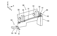
実施形態に係るテープ自動装填装置1について、図面を用いて説明する。テープ自動装填装置1は、テープフィーダ100にキャリアテープ200を自動的に装填する装置である。テープ自動装填装置1は、図1に示す如く、フィーダ保持台10と、第一テープ搬送装置20と、第二テープ搬送装置30と、第一開放装置40と、第二開放装置50と、カバーテープ処理装置60と、を備えている。 The tape automatic loading device 1 according to the embodiment will be described with reference to the drawings. The tape automatic loading device 1 is a device that automatically loads the carrier tape 200 into the tape feeder 100. As shown in FIG. 1, the tape automatic loading device 1 includes a feeder holding base 10, a first tape transfer device 20, a second tape transfer device 30, a first release device 40, a second release device 50, and a cover. A tape processing device 60 and the like are provided.

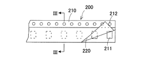
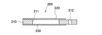
まず、図2及び図3を用いて、キャリアテープ200の構成について説明する。キャリアテープ200は、複数の部品を長手方向に一列に収容したテープ部材である。キャリアテープ200は、図2及び図3に示す如く、ベーステープ210と、カバーテープ220と、を有している。ベーステープ210は、紙材や樹脂等の柔軟な材料により構成されている。ベーステープ210には、収容孔211が設けられている。収容孔211は、部品を収容することが可能な収容部である。収容孔211は、ベーステープ210の長手方向において所定間隔ごとに設けられている。また、部品は、基板に装着される電子部品などであって、例えば0201サイズ(0.2mm×0.1mm)などの微小部品であってよい。 First, the configuration of the carrier tape 200 will be described with reference to FIGS. 2 and 3. The carrier tape 200 is a tape member in which a plurality of parts are housed in a row in the longitudinal direction. The carrier tape 200 has a base tape 210 and a cover tape 220 as shown in FIGS. 2 and 3. The base tape 210 is made of a flexible material such as paper or resin. The base tape 210 is provided with accommodating holes 211. The accommodating hole 211 is an accommodating portion capable of accommodating parts. The accommodating holes 211 are provided at predetermined intervals in the longitudinal direction of the base tape 210. Further, the component may be an electronic component mounted on the substrate, and may be a minute component having a size of 0201 (0.2 mm × 0.1 mm), for example.

尚、キャリアテープ200は、ベーステープ210で収容孔211が貫通したものであってもよいし、また、ベーステープ210で収容孔211が閉じたエンボス型であってもよい。また、キャリアテープ200は、図3に示す如くベーステープ210で収容孔211が貫通する構造であるときは、その収容孔211に収容された部品を保持してその部品の脱落を防止するため、更に、ベーステープ210の下面に接着されるボトムテープ230を有する。このボトムテープ230は、透明又は半透明の紙材や高分子フィルムなどにより構成される。 The carrier tape 200 may be a base tape 210 through which the accommodating holes 211 penetrate, or an embossed type in which the accommodating holes 211 are closed by the base tape 210. Further, when the carrier tape 200 has a structure in which the accommodating hole 211 penetrates through the base tape 210 as shown in FIG. 3, in order to hold the component accommodated in the accommodating hole 211 and prevent the component from falling off. Further, it has a bottom tape 230 that is adhered to the lower surface of the base tape 210. The bottom tape 230 is made of a transparent or translucent paper material, a polymer film, or the like.

ベーステープ210には、また、係合孔212が貫通して設けられている。係合孔212は、後述のスプロケットの係合突起を係合させる送り孔である。係合孔212は、略円形或いは楕円形に形成されている。係合孔212は、後述のスプロケットの係合突起が係合することが可能な大きさを有している。係合孔212は、ベーステープ210の長手方向において所定間隔ごとに設けられている。上記の収容孔211は、ベーステープ210の幅方向の一方側において長手方向に一列に配置されている。また、上記の係合孔212は、ベーステープ210の幅方向の他方側において長手方向に一列に配置されている。 The base tape 210 is also provided with an engaging hole 212 penetrating through the base tape 210. The engagement hole 212 is a feed hole for engaging the engagement projection of the sprocket described later. The engagement hole 212 is formed in a substantially circular or elliptical shape. The engaging hole 212 has a size capable of engaging the engaging projection of the sprocket described later. Engagement holes 212 are provided at predetermined intervals in the longitudinal direction of the base tape 210. The accommodating holes 211 are arranged in a row in the longitudinal direction on one side in the width direction of the base tape 210. Further, the engaging holes 212 are arranged in a row in the longitudinal direction on the other side in the width direction of the base tape 210.

カバーテープ220は、ベーステープ210の上面(尚、係合孔212が設けられている部分は除外されてよい。)に接着剤により接着されている。カバーテープ220のベーステープ210への接着は、キャリアテープ200における収容孔211の幅方向位置を避けてその幅方向両側それぞれにおいて行われる。カバーテープ220は、ベーステープ210の収容孔211の上部を閉塞して、その収容孔211に収容された部品の飛び出しを防止する機能を有している。カバーテープ220は、透明な高分子フィルムなどにより構成されている。 The cover tape 220 is adhered to the upper surface of the base tape 210 (note that the portion provided with the engaging hole 212 may be excluded) with an adhesive. Adhesion of the cover tape 220 to the base tape 210 is performed on both sides in the width direction of the carrier tape 200, avoiding the position in the width direction of the accommodating holes 211. The cover tape 220 has a function of closing the upper portion of the accommodating hole 211 of the base tape 210 to prevent the parts accommodated in the accommodating hole 211 from popping out. The cover tape 220 is made of a transparent polymer film or the like.

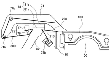
次に、図4−図6を用いて、テープフィーダ100の構成について説明する。テープフィーダ100は、キャリアテープ200を搬送することにより、基板に装着すべき部品を部品吸着位置Lに供給する装置である。テープフィーダ100は、基板を生産する基板生産ライン上に設けられる部品装着機の有するスロットに着脱可能に装着される。テープフィーダ100から部品吸着位置Lに供給された部品は、部品装着機の装着ヘッドに取り付けられた吸着ノズルなどで吸着保持され、その後、吸着解除により基板に装着される。 Next, the configuration of the tape feeder 100 will be described with reference to FIGS. 4 to 6. The tape feeder 100 is a device that supplies the components to be mounted on the substrate to the component suction position L by transporting the carrier tape 200. The tape feeder 100 is detachably mounted in a slot of a component mounting machine provided on a board production line that produces a board. The component supplied from the tape feeder 100 to the component suction position L is sucked and held by a suction nozzle or the like attached to the mounting head of the component mounting machine, and then mounted on the substrate by releasing the suction.

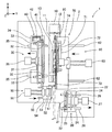
テープフィーダ100は、図4に示す如く、フィーダ本体110と、リール収容部120と、テープ送り機構部130と、を有している。フィーダ本体110は、扁平な箱形に形成されている。フィーダ本体110は、テープ送りガイド111を有している。テープ送りガイド111は、フィーダ本体110の上部に設けられている。リール収容部120は、フィーダ本体110の後端側に配置されている。リール収容部120は、キャリアテープ200が巻回された円盤状のテープリール240を収容する部位である。キャリアテープ200は、リール収容部120に収容されたテープリール240から引き出されてテープ送りガイド111により案内される。テープ送りガイド111は、リール収容部120とテープ送り機構部130との間でキャリアテープ200を案内するテープ経路を形成している。 As shown in FIG. 4, the tape feeder 100 includes a feeder main body 110, a reel accommodating portion 120, and a tape feeding mechanism portion 130. The feeder body 110 is formed in a flat box shape. The feeder body 110 has a tape feed guide 111. The tape feed guide 111 is provided on the upper portion of the feeder main body 110. The reel accommodating portion 120 is arranged on the rear end side of the feeder main body 110. The reel accommodating portion 120 is a portion for accommodating the disk-shaped tape reel 240 around which the carrier tape 200 is wound. The carrier tape 200 is pulled out from the tape reel 240 housed in the reel housing section 120 and guided by the tape feed guide 111. The tape feed guide 111 forms a tape path for guiding the carrier tape 200 between the reel accommodating portion 120 and the tape feed mechanism portion 130.

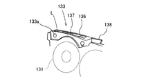
テープ送り機構部130は、フィーダ本体110の前端側に配置されている。テープ送り機構部130は、テープリール240から引き出されたキャリアテープ200をピッチ送りする機構部である。テープ送り機構部130は、スプロケット131と、モータ132と、第一テープ保持部133と、を有している。尚、テープ送り機構部130は、フィーダ本体110の前端側だけでなく、その後端側にも配置されていてもよい。 The tape feeding mechanism unit 130 is arranged on the front end side of the feeder main body 110. The tape feed mechanism unit 130 is a mechanism unit that pitch-feeds the carrier tape 200 drawn from the tape reel 240. The tape feeding mechanism unit 130 includes a sprocket 131, a motor 132, and a first tape holding unit 133. The tape feeding mechanism unit 130 may be arranged not only on the front end side of the feeder main body 110 but also on the rear end side.

スプロケット131は、フィーダ本体110におけるテープ搬送路の下方に設けられた円盤状の部材である。スプロケット131は、フィーダ本体110の前端側に回転可能に取り付けられている。スプロケット131は、テープ送りガイド111により案内されているキャリアテープ200を搬送させる方向に回転する。スプロケット131は、外周面において径方向外側に向けて突出する外歯である係合突起を有している。この係合突起は、その外周全周に亘って所定角度ごとに設けられている。 The sprocket 131 is a disk-shaped member provided below the tape transport path in the feeder main body 110. The sprocket 131 is rotatably attached to the front end side of the feeder main body 110. The sprocket 131 rotates in the direction of conveying the carrier tape 200 guided by the tape feed guide 111. The sprocket 131 has engaging protrusions which are external teeth protruding outward in the radial direction on the outer peripheral surface. The engaging protrusions are provided at predetermined angles over the entire circumference thereof.

スプロケット131には、ギヤを介してモータ132が連結されている。モータ132は、スプロケット131を回転駆動させるサーボモータである。モータ132が回転駆動されると、その回転がギヤを用いて減速されつつスプロケット131に伝達されることで、スプロケット131が回転する。モータ132は、スプロケット131が間欠的に回転するように駆動される。スプロケット131が回転すると、その係合突起がテープ送りガイド111により案内されているキャリアテープ200の係合孔212に係合するので、そのキャリアテープ200が搬送方向Xに搬送される。キャリアテープ200の搬送は、所定ピッチずつ行われる。 A motor 132 is connected to the sprocket 131 via a gear. The motor 132 is a servomotor that rotationally drives the sprocket 131. When the motor 132 is rotationally driven, the rotation is transmitted to the sprocket 131 while being decelerated by using a gear, so that the sprocket 131 rotates. The motor 132 is driven so that the sprocket 131 rotates intermittently. When the sprocket 131 rotates, its engaging projection engages with the engaging hole 212 of the carrier tape 200 guided by the tape feed guide 111, so that the carrier tape 200 is conveyed in the conveying direction X. The carrier tape 200 is conveyed at predetermined pitch intervals.

第一テープ保持部133は、係合孔212にスプロケット131の係合突起が係合するキャリアテープ200を保持する部位である。第一テープ保持部133は、キャリアテープ200の上面を上方から覆う。第一テープ保持部133の上面には、窓孔が設けられていると共に、開口孔が設けられている。スプロケット131は、上端付近に達した係合突起が窓孔を通じてテープ搬送路上に突出するように配置される。係合突起は、テープ搬送路上に突出した状態でキャリアテープ200の係合孔212に係合する。上記の開口孔は、部品吸着位置Lに設けられている。 The first tape holding portion 133 is a portion that holds the carrier tape 200 in which the engaging projection of the sprocket 131 engages with the engaging hole 212. The first tape holding portion 133 covers the upper surface of the carrier tape 200 from above. A window hole is provided and an opening hole is provided on the upper surface of the first tape holding portion 133. The sprocket 131 is arranged so that the engaging protrusion reaching the vicinity of the upper end protrudes onto the tape transport path through the window hole. The engaging protrusion engages with the engaging hole 212 of the carrier tape 200 in a state of protruding on the tape transport path. The opening hole is provided at the component suction position L.

図5に示す如く、第一テープ保持部133の上面には、テープ剥離部材136及びテープ折返部材137が設けられている。テープ剥離部材136は、上記開口孔の搬送方向上流側に配置されている。テープ剥離部材136は、キャリアテープ200のベーステープ210からカバーテープ220を剥離する剥離刃である。テープ折返部材137は、ベーステープ210から剥離したカバーテープ220の幅方向一方側(具体的には、キャリアテープ200における部品を収容する収容孔211が配置された側)を立ち上げて折り返す部材である。 As shown in FIG. 5, a tape peeling member 136 and a tape folding member 137 are provided on the upper surface of the first tape holding portion 133. The tape peeling member 136 is arranged on the upstream side of the opening hole in the transport direction. The tape peeling member 136 is a peeling blade that peels the cover tape 220 from the base tape 210 of the carrier tape 200. The tape folding member 137 is a member that raises and folds one side of the cover tape 220 peeled off from the base tape 210 in the width direction (specifically, the side on which the accommodating holes 211 of the carrier tape 200 are arranged). is there.

第一テープ保持部133には、回転支点133aが設けられている。回転支点133aは、第一テープ保持部133の後端側が上方へ移動可能となるように前端部に配置されている。第一テープ保持部133の後端部には、作業者が操作可能なレバー138が突設されている。第一テープ保持部133の後端部とフィーダ本体110との間には、その第一テープ保持部133の後端側を下方に付勢する付勢部材(図示せず)が組み付けられている。第一テープ保持部133は、レバー138が持ち上げられていないときはスプロケット131との間でキャリアテープ200を保持し、一方、レバー138が付勢部材の付勢力に抗して持ち上げられたときにスプロケット131との間におけるキャリアテープ200の保持を解除する。 The first tape holding portion 133 is provided with a rotation fulcrum 133a. The rotation fulcrum 133a is arranged at the front end portion so that the rear end side of the first tape holding portion 133 can move upward. A lever 138 that can be operated by an operator is projected from the rear end of the first tape holding portion 133. An urging member (not shown) for urging the rear end side of the first tape holding portion 133 downward is assembled between the rear end portion of the first tape holding portion 133 and the feeder main body 110. .. The first tape holding portion 133 holds the carrier tape 200 between the lever 138 and the sprocket 131 when the lever 138 is not lifted, while the first tape holding portion 133 holds the carrier tape 200 when the lever 138 is lifted against the urging force of the urging member. The carrier tape 200 is released from being held between the sprocket 131 and the carrier tape 200.

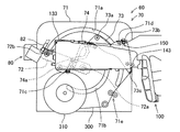
テープフィーダ100は、また、カバーテープ送り出し機構部140を有している。カバーテープ送り出し機構部140は、フィーダ本体110の中央下部に配置されている。カバーテープ送り出し機構部140は、テープ剥離部材136で剥離されてテープ折返部材137で折り返されたカバーテープ220をキャリアテープ200の搬送方向Xとは反対方向に送り出す機構部である。カバーテープ送り出し機構部140は、ギヤ141と、モータ142と、第二テープ保持部143と、を有している。 The tape feeder 100 also has a cover tape feeding mechanism unit 140. The cover tape feeding mechanism unit 140 is arranged at the lower center of the feeder main body 110. The cover tape feeding mechanism unit 140 is a mechanism unit that feeds the cover tape 220 that has been peeled off by the tape peeling member 136 and folded back by the tape folding member 137 in the direction opposite to the transport direction X of the carrier tape 200. The cover tape feeding mechanism unit 140 includes a gear 141, a motor 142, and a second tape holding unit 143.

ギヤ141は、フィーダ本体110の中央下部に回転可能に取り付けられている。ギヤ141には、モータ142が連結されている。モータ142は、ギヤ141を回転駆動させるサーボモータである。第二テープ保持部143は、送り出すカバーテープ220を、フィーダ本体110から外れないように保持する部位である。第二テープ保持部143は、図6に示す如く、ギヤ144と、アーム145と、レバー146と、コイルバネ147と、を有している。 The gear 141 is rotatably attached to the lower center of the feeder body 110. A motor 142 is connected to the gear 141. The motor 142 is a servomotor that rotationally drives the gear 141. The second tape holding portion 143 is a portion that holds the cover tape 220 to be sent out so as not to come off from the feeder main body 110. As shown in FIG. 6, the second tape holding portion 143 has a gear 144, an arm 145, a lever 146, and a coil spring 147.

ギヤ144は、上記のギヤ141と噛合している。アーム145には、回転支点145aが設けられている。アーム145は、回転支点145aを中心にしてギヤ144をギヤ141側に移動させることが可能となるように形成されている。レバー146は、アーム145から下方へ突出している。コイルバネ147は、レバー146を介してアーム145をギヤ141側に付勢する付勢力を発生する。第二テープ保持部143は、レバー146が移動されていないときはコイルバネ147の付勢力によりギヤ144をギヤ141と噛合させてカバーテープ220を保持し、一方、レバー146がコイルバネ147の付勢力に抗して移動されたときにギヤ144をギヤ141から離間させてカバーテープ220の保持を解除する。 The gear 144 meshes with the above gear 141. The arm 145 is provided with a rotation fulcrum 145a. The arm 145 is formed so that the gear 144 can be moved to the gear 141 side about the rotation fulcrum 145a. The lever 146 projects downward from the arm 145. The coil spring 147 generates an urging force that urges the arm 145 toward the gear 141 side via the lever 146. When the lever 146 is not moved, the second tape holding portion 143 engages the gear 144 with the gear 141 by the urging force of the coil spring 147 to hold the cover tape 220, while the lever 146 acts as the urging force of the coil spring 147. When moved against it, the gear 144 is separated from the gear 141 to release the holding of the cover tape 220.

テープフィーダ100は、また、カバーテープ送りガイド150を有している。カバーテープ送りガイド150は、テープフィーダ100のテープ剥離部材136とカバーテープ送り出し機構部140との間に設けられている。カバーテープ送りガイド150は、テープ剥離部材136で剥離されたカバーテープ220をカバーテープ送り出し機構部140に案内する。カバーテープ送りガイド150は、一対のガイドローラ151,152により構成されている。ガイドローラ151,152は、テープ送りガイド111上に案内されるキャリアテープ200よりも上方に配置されている。テープフィーダ100の前端側に配置されたガイドローラ151は、カバーテープ220の弛みを防止するためにカバーテープ220に張力を付与する役割を有している。 The tape feeder 100 also has a cover tape feed guide 150. The cover tape feeding guide 150 is provided between the tape peeling member 136 of the tape feeder 100 and the cover tape feeding mechanism portion 140. The cover tape feed guide 150 guides the cover tape 220 peeled by the tape peeling member 136 to the cover tape feeding mechanism unit 140. The cover tape feed guide 150 is composed of a pair of guide rollers 151 and 152. The guide rollers 151 and 152 are arranged above the carrier tape 200 guided on the tape feed guide 111. The guide roller 151 arranged on the front end side of the tape feeder 100 has a role of applying tension to the cover tape 220 in order to prevent the cover tape 220 from loosening.

キャリアテープ200は、搬送方向Xへ搬送されるうえで、まず、テープリール240から引き出されてテープ送りガイド111により案内されて第一テープ保持部133に保持される。そして、その第一テープ保持部133に保持された状態でモータ132の回転により搬送方向Xへ搬送される。キャリアテープ200は、その搬送中、ベーステープ210とカバーテープ220との間にテープ剥離部材136が進入することで、ベーステープ210からカバーテープ220が剥離された状態になる。ベーステープ210から剥離したカバーテープ220は、第一テープ保持部133から第二テープ保持部143まで、一対のガイドローラ151,152を経由した経路(以下、排出経路と称す。)で取り回される。そして、そのカバーテープ220は、その第二テープ保持部143に保持された状態で、上記モータ132の回転と同期したモータ142の回転によりフィーダ本体110の外方(具体的には、第二テープ保持部143の下方)へ排出される。 In transporting the carrier tape 200 in the transport direction X, the carrier tape 200 is first pulled out from the tape reel 240, guided by the tape feed guide 111, and held by the first tape holding portion 133. Then, while being held by the first tape holding portion 133, the motor 132 is rotated to transport the motor 132 in the transport direction X. During the transportation of the carrier tape 200, the cover tape 220 is peeled from the base tape 210 by the tape peeling member 136 entering between the base tape 210 and the cover tape 220. The cover tape 220 peeled off from the base tape 210 is routed from the first tape holding portion 133 to the second tape holding portion 143 by a route via a pair of guide rollers 151 and 152 (hereinafter, referred to as a discharge route). The cover. Then, the cover tape 220 is held by the second tape holding portion 143, and the rotation of the motor 142 synchronized with the rotation of the motor 132 causes the outer side of the feeder main body 110 (specifically, the second tape). It is discharged to the lower side of the holding portion 143).

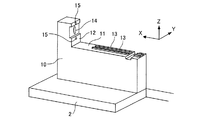
次に、図7−図15を用いて、テープ自動装填装置1の構成について説明する。テープ自動装填装置1において、フィーダ保持台10は、上記のテープフィーダ100を保持する台座である。フィーダ保持台10は、図7に示す如く、テープ自動装填装置1の基台2の中央部に配置されている。フィーダ保持台10は、載置部11と、当接部12と、を有している。載置部11には、テープフィーダ100のフィーダ本体110の底面が載置される。当接部12には、フィーダ本体110の前端面が当接される。載置部11には、フィーダ本体110の両側面の下部を挟持する一対の支持ガイド13が設けられている。当接部12には、テープフィーダ100に対して通信可能かつ電力供給可能な通信ジャック14、及び、テープフィーダ100を位置決めする位置決め部15と、が設けられている。 Next, the configuration of the tape automatic loading device 1 will be described with reference to FIGS. 7 to 15. In the tape automatic loading device 1, the feeder holding base 10 is a pedestal for holding the tape feeder 100. As shown in FIG. 7, the feeder holding base 10 is arranged at the center of the base 2 of the automatic tape loading device 1. The feeder holding base 10 has a mounting portion 11 and a contact portion 12. The bottom surface of the feeder main body 110 of the tape feeder 100 is mounted on the mounting portion 11. The front end surface of the feeder main body 110 is brought into contact with the contact portion 12. The mounting portion 11 is provided with a pair of support guides 13 that sandwich the lower portions of both side surfaces of the feeder main body 110. The contact portion 12 is provided with a communication jack 14 capable of communicating with and supplying power to the tape feeder 100, and a positioning portion 15 for positioning the tape feeder 100.

第一テープ搬送装置20及び第二テープ搬送装置30はそれぞれ、キャリアテープ200を搬送方向Xへ搬送させる装置である。第一テープ搬送装置20と第二テープ搬送装置30とは、基台2上において、フィーダ保持台10に保持されたテープフィーダ100を挟んだ斜向かいに配置されている。第一テープ搬送装置20及び第二テープ搬送装置30はそれぞれ、基台2上において、フィーダ保持台10に保持されたテープフィーダ100を両側から挟む方向に進退することが可能である。 The first tape transfer device 20 and the second tape transfer device 30 are devices for transporting the carrier tape 200 in the transport direction X, respectively. The first tape transfer device 20 and the second tape transfer device 30 are arranged on the base 2 diagonally opposite to each other with the tape feeder 100 held by the feeder holding table 10 sandwiched between them. The first tape transfer device 20 and the second tape transfer device 30 can each move forward and backward on the base 2 in a direction in which the tape feeder 100 held by the feeder holding base 10 is sandwiched from both sides.

第一テープ搬送装置20は、図8に示す如く、ガイド21と、二つの駆動ローラ22と、二つの従動ローラ23と、二つのギヤモータ24と、を有している。ガイド21は、搬送方向Xに搬送されるキャリアテープ200を案内する。二つの駆動ローラ22は、搬送方向Xに互いに離間して配置されている。二つの従動ローラ23はそれぞれ、対応の駆動ローラ22の下方に配置されており、付勢部材(図示せず)で対応の駆動ローラ22側に付勢されている。二つのギヤモータ24はそれぞれ、対応の駆動ローラ22を回転駆動する。ガイド21は、後端側のローラ22,23よりも後方側、二対のローラ22,23の間、及び前端側のローラ22,23よりも前方側にそれぞれ、上下一対で配置されている。 As shown in FIG. 8, the first tape transfer device 20 includes a guide 21, two drive rollers 22, two driven rollers 23, and two gear motors 24. The guide 21 guides the carrier tape 200 to be conveyed in the conveying direction X. The two drive rollers 22 are arranged apart from each other in the transport direction X. Each of the two driven rollers 23 is arranged below the corresponding drive roller 22, and is urged to the corresponding drive roller 22 side by an urging member (not shown). Each of the two gear motors 24 rotationally drives the corresponding drive roller 22. The guides 21 are arranged in pairs on the rear side of the rear end side rollers 22 and 23, between the two pairs of rollers 22 and 23, and on the front side of the front end side rollers 22 and 23, respectively.

第一テープ搬送装置20は、台座25に載置固定されている。台座25は、一対のレール26上に搬送方向Xに直交する水平な方向(以下、直交方向と称す。)Yにスライド可能に取り付けられている。一対のレール26は、基台2上に所定間隔を空けてそれぞれ直交方向Yに延在するように設けられている。台座25は、基台2に固定されたエアシリンダ27に接続されている。エアシリンダ27は、外部のエア供給源(図示せず)に接続されている。台座25は、エアシリンダ27からのエアにより基台2上で一対のレール26に沿って直交方向Yへスライドすることが可能である。 The first tape transfer device 20 is placed and fixed on the pedestal 25. The pedestal 25 is slidably mounted on a pair of rails 26 in a horizontal direction (hereinafter, referred to as an orthogonal direction) Y orthogonal to the transport direction X. The pair of rails 26 are provided on the base 2 so as to extend in the orthogonal direction Y at predetermined intervals. The pedestal 25 is connected to an air cylinder 27 fixed to the base 2. The air cylinder 27 is connected to an external air supply source (not shown). The pedestal 25 can slide in the orthogonal direction Y along the pair of rails 26 on the base 2 by the air from the air cylinder 27.

第二テープ搬送装置30は、図9に示す如く、ガイド31と、二つの駆動ローラ32と、二つのギヤモータ33と、を有している。ガイド31は、搬送方向Xに搬送されるキャリアテープ200を案内する。二つの駆動ローラ32は、搬送方向Xに互いに離間して配置されている。二つのギヤモータ33はそれぞれ、対応の駆動ローラ32を回転駆動する。ガイド31は、後端側の駆動ローラ32よりも後方側、二つの駆動ローラ32の間、及び前端側の駆動ローラ32よりも前方側にそれぞれ配置されている。 As shown in FIG. 9, the second tape transfer device 30 includes a guide 31, two drive rollers 32, and two gear motors 33. The guide 31 guides the carrier tape 200 to be conveyed in the conveying direction X. The two drive rollers 32 are arranged apart from each other in the transport direction X. Each of the two gear motors 33 rotationally drives the corresponding drive roller 32. The guides 31 are arranged on the rear side of the drive roller 32 on the rear end side, between the two drive rollers 32, and on the front side of the drive roller 32 on the front end side.

第二テープ搬送装置30は、台座34に載置固定されている。台座34は、一対のレール35上に搬送方向Xに直交する直交方向Yにスライド可能に取り付けられている。一対のレール35は、基台2上に所定間隔を空けてそれぞれ直交方向Yに延在するように設けられている。台座34は、基台2に固定されたエアシリンダ36に接続されている。エアシリンダ36は、外部のエア供給源(図示せず)に接続されている。台座34は、エアシリンダ36からのエアにより基台2上で一対のレール35に沿って直交方向Yへスライドすることが可能である。 The second tape transfer device 30 is placed and fixed on the pedestal 34. The pedestal 34 is slidably mounted on the pair of rails 35 in the orthogonal direction Y orthogonal to the transport direction X. The pair of rails 35 are provided on the base 2 so as to extend in the orthogonal direction Y at predetermined intervals. The pedestal 34 is connected to an air cylinder 36 fixed to the base 2. The air cylinder 36 is connected to an external air supply source (not shown). The pedestal 34 can slide in the orthogonal direction Y along the pair of rails 35 on the base 2 by the air from the air cylinder 36.

上記の如くフィーダ保持台10にテープフィーダ100が保持されかつ第一及び第二テープ搬送装置20,30がそのテープフィーダ100に接近した状態で直交方向Yにスライドされると、そのテープフィーダ100により搬送されるキャリアテープ200は、第一テープ搬送装置20の上下一対のガイド21の間隙を通って案内されると共に、第二テープ搬送装置30のガイド31とテープフィーダ100のテープ送りガイド111との間隙を通って案内される。 When the tape feeder 100 is held on the feeder holding table 10 as described above and the first and second tape transfer devices 20 and 30 are slid in the orthogonal direction Y in a state of being close to the tape feeder 100, the tape feeder 100 causes the tape feeder 100 to slide. The carrier tape 200 to be conveyed is guided through the gap between the pair of upper and lower guides 21 of the first tape transfer device 20, and the guide 31 of the second tape transfer device 30 and the tape feed guide 111 of the tape feeder 100. You will be guided through the gap.

第一開放装置40及び第二開放装置50はそれぞれ、テープフィーダ100の第一テープ保持部133によるキャリアテープ200の保持又は第二テープ保持部143によるカバーテープ220の保持を解除して開放する装置である。第一開放装置40及び第二開放装置50はそれぞれ、基台2上において、フィーダ保持台10に保持されたテープフィーダ100の配置位置に対して第二テープ搬送装置30側に配置されている。 The first opening device 40 and the second opening device 50 are devices for releasing the holding of the carrier tape 200 by the first tape holding portion 133 of the tape feeder 100 or the holding of the cover tape 220 by the second tape holding portion 143, respectively. Is. The first opening device 40 and the second opening device 50 are respectively arranged on the base 2 on the second tape transfer device 30 side with respect to the arrangement position of the tape feeder 100 held by the feeder holding table 10.

第一開放装置40は、第一リフトレバー41と、支持台42と、エアシリンダ43と、を有している。第一リフトレバー41は、第一テープ保持部133のレバー138に当接してそのレバー138を上下方向Zに移動させることが可能である。支持台42は、第一リフトレバー41の先端がテープフィーダ100側に突出するように第一リフトレバー41を支持している。エアシリンダ43は、第二テープ搬送装置30の台座34上に固定されている。エアシリンダ43は、エア供給源からのエアにより、支持台42を上下方向Zに移動させることが可能である。 The first opening device 40 includes a first lift lever 41, a support base 42, and an air cylinder 43. The first lift lever 41 can come into contact with the lever 138 of the first tape holding portion 133 and move the lever 138 in the vertical direction Z. The support base 42 supports the first lift lever 41 so that the tip of the first lift lever 41 projects toward the tape feeder 100 side. The air cylinder 43 is fixed on the pedestal 34 of the second tape transfer device 30. The air cylinder 43 can move the support base 42 in the vertical direction Z by the air from the air supply source.

第二開放装置50は、第二リフトレバー51と、支持台52と、エアシリンダ53と、を有している。第二リフトレバー51は、第二テープ保持部143のレバー146に当接してそのレバー146を搬送方向Xに移動させることが可能である。支持台52は、第二リフトレバー51の先端がテープフィーダ100側に突出するように第二リフトレバー51を支持している。エアシリンダ53は、台座54上に固定されている。エアシリンダ53は、支持台52を搬送方向Xに移動させることが可能である。 The second opening device 50 includes a second lift lever 51, a support base 52, and an air cylinder 53. The second lift lever 51 can come into contact with the lever 146 of the second tape holding portion 143 and move the lever 146 in the transport direction X. The support base 52 supports the second lift lever 51 so that the tip of the second lift lever 51 projects toward the tape feeder 100 side. The air cylinder 53 is fixed on the pedestal 54. The air cylinder 53 can move the support base 52 in the transport direction X.

台座54は、一対のレール55上に直交方向Yにスライド可能に取り付けられている。一対のレール55は、基台2上に所定間隔を空けてそれぞれ直交方向Yに延在するように設けられている。台座54は、基台2に固定されたエアシリンダ56に接続されている。エアシリンダ56は、エア供給源からのエアにより基台2上で一対のレール55に沿って台座54を直交方向Yへスライドさせることが可能であって、支持台52を直交方向Yに移動させることが可能である。 The pedestal 54 is slidably mounted on the pair of rails 55 in the orthogonal direction Y. The pair of rails 55 are provided on the base 2 so as to extend in the orthogonal direction Y at predetermined intervals. The pedestal 54 is connected to an air cylinder 56 fixed to the base 2. The air cylinder 56 can slide the pedestal 54 in the orthogonal direction Y along the pair of rails 55 on the base 2 by the air from the air supply source, and moves the support base 52 in the orthogonal direction Y. It is possible.

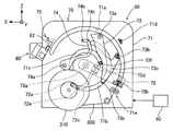
カバーテープ処理装置60は、フィーダ保持台10に保持されかつキャリアテープ200のベーステープ210からカバーテープ220を剥離したテープフィーダ100に、後述の仮テープを移載することにより、その剥離されたカバーテープ220をフィーダ本体110の外方へ排出する装置である。カバーテープ処理装置60は、基台2上において、フィーダ保持台10に保持されたテープフィーダ100のカバーテープ送り出し機構部140が露呈している側すなわちそのテープフィーダ100の配置位置に対して第一テープ搬送装置20側に配置されている。カバーテープ処理装置60は、図10に示す如く、仮テープ配策装置70と、カバーテープ把持装置75と、連結装置80と、移載装置90と、を有している。 The cover tape processing device 60 is held on the feeder holding table 10 and the cover tape 220 is peeled off from the base tape 210 of the carrier tape 200. By transferring the temporary tape described later to the tape feeder 100, the peeled cover is peeled off. This is a device for discharging the tape 220 to the outside of the feeder main body 110. The cover tape processing device 60 is first on the base 2 with respect to the side where the cover tape feeding mechanism portion 140 of the tape feeder 100 held by the feeder holding base 10 is exposed, that is, the arrangement position of the tape feeder 100. It is arranged on the tape transfer device 20 side. As shown in FIG. 10, the cover tape processing device 60 includes a temporary tape arrangement device 70, a cover tape gripping device 75, a connecting device 80, and a transfer device 90.

仮テープ配策装置70は、仮テープ300をカバーテープ220の排出経路に倣った経路に沿って配策して保持する装置である。尚、この経路は、図11において太実線で示されている。仮テープ300は、テープリール240に巻回されているキャリアテープ200とは異なるテープであって、キャリアテープ200のベーステープ210から剥離されたカバーテープ220に連結された後にテープフィーダ100に移載される。仮テープ300は、キャリアテープ200のカバーテープ220と同じ形状で同じ素材により形成されている。仮テープ300は、仮テープ配策装置70に装着可能な仮テープリール310に巻回されている。 The temporary tape arranging device 70 is a device that arranges and holds the temporary tape 300 along a path following the discharge path of the cover tape 220. This route is shown by a thick solid line in FIG. The temporary tape 300 is a tape different from the carrier tape 200 wound around the tape reel 240, and is transferred to the tape feeder 100 after being connected to the cover tape 220 peeled from the base tape 210 of the carrier tape 200. Will be done. The temporary tape 300 has the same shape as the cover tape 220 of the carrier tape 200 and is made of the same material. The temporary tape 300 is wound around a temporary tape reel 310 that can be attached to the temporary tape distribution device 70.

仮テープ配策装置70は、台座61に載置固定されている。台座61は、一対のレール62上に直交方向Yにスライド可能に取り付けられている。一対のレール62は、基台2上に所定間隔を空けてそれぞれ直交方向Yに延在するように設けられている。台座61は、基台2に固定されたエアシリンダ63に接続されている。エアシリンダ63は、外部のエア供給源(図示せず)に接続されている。台座61は、エアシリンダ63からのエアにより基台2上で一対のレール62に沿って直交方向Yへスライドすることが可能である。 The temporary tape distribution device 70 is placed and fixed on the pedestal 61. The pedestal 61 is slidably mounted on the pair of rails 62 in the orthogonal direction Y. The pair of rails 62 are provided on the base 2 so as to extend in the orthogonal direction Y at predetermined intervals. The pedestal 61 is connected to an air cylinder 63 fixed to the base 2. The air cylinder 63 is connected to an external air supply source (not shown). The pedestal 61 can slide in the orthogonal direction Y along the pair of rails 62 on the base 2 by the air from the air cylinder 63.

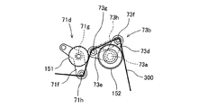
仮テープ配策装置70は、本体プレート71と、移送部72と、第一押出部73と、第二押出部74と、を有している。本体プレート71は、略矩形状に形成された平板部材である。本体プレート71には、それぞれ円環状かつ円弧状の三つの案内孔71a,71b,71cが同心円上に形成されている。本体プレート71には、外側支持ピン機構部71d及び一対の仮テープ支持ローラ71eがそれぞれ取り付けられている。外側支持ピン機構部71dは、仮テープ300を外側から接触して支持する。外側支持ピン機構部71dは、支持プレート71fを有している。支持プレート71fは、回転支点71gにより本体プレート71に回転可能である。支持プレート71fの先端部には、仮テープ300を支持するためのピン71hが直交方向Yに突出するように取り付けられている。仮テープ支持ローラ71eは、仮テープリール310から引き出された仮テープ300を案内支持する。 The temporary tape distribution device 70 includes a main body plate 71, a transfer unit 72, a first extrusion unit 73, and a second extrusion unit 74. The main body plate 71 is a flat plate member formed in a substantially rectangular shape. The main body plate 71 is formed with three annular and arcuate guide holes 71a, 71b, and 71c, respectively, on concentric circles. An outer support pin mechanism portion 71d and a pair of temporary tape support rollers 71e are attached to the main body plate 71, respectively. The outer support pin mechanism portion 71d contacts and supports the temporary tape 300 from the outside. The outer support pin mechanism portion 71d has a support plate 71f. The support plate 71f can be rotated to the main body plate 71 by the rotation fulcrum 71g. A pin 71h for supporting the temporary tape 300 is attached to the tip of the support plate 71f so as to project in the orthogonal direction Y. The temporary tape support roller 71e guides and supports the temporary tape 300 drawn from the temporary tape reel 310.

移送部72は、本体プレート71の背面側(すなわち、フィーダ保持台10側とは反対側)に配置されている。移送部72は、回転支点72aにより案内孔71aの円弧中心において回転可能に支持されている。移送部72の先端部には、把持爪72bが設けられている。把持爪72bは、本体プレート71において最大径を有する案内孔71aの縁部に支持されている。把持爪72bは、本体プレート71の正面側(すなわち、フィーダ保持台10側)で仮テープ300を把持することが可能である。 The transfer portion 72 is arranged on the back side of the main body plate 71 (that is, the side opposite to the feeder holding base 10 side). The transfer portion 72 is rotatably supported at the center of the arc of the guide hole 71a by the rotation fulcrum 72a. A gripping claw 72b is provided at the tip of the transfer portion 72. The gripping claw 72b is supported by the edge of the guide hole 71a having the maximum diameter in the main body plate 71. The gripping claw 72b can grip the temporary tape 300 on the front side (that is, the feeder holding base 10 side) of the main body plate 71.

移送部72には、アーム72c,72dが固定されている。アーム72c,72dはそれぞれ、回転支点72aと把持爪72bとの間の移送部72から周方向に向けて延びている。アーム72cは、移送部72に対して下方側に位置している。アーム72cの先端部には、二つの接触ローラ72eが回転可能に支持されている。接触ローラ72eはそれぞれ、本体プレート71において中間径を有する案内孔71bの縁部に支持されている。接触ローラ72eはそれぞれ、本体プレート71の正面側に突出している。アーム72dは、移送部72に対して上方側に位置している。アーム72dの先端部には、接触ローラ72fが回転可能に支持されている。接触ローラ72fは、本体プレート71において最小径を有する案内孔71cの縁部に支持されている。接触ローラ72fは、本体プレート71の正面側に突出している。 Arms 72c and 72d are fixed to the transfer unit 72. The arms 72c and 72d each extend in the circumferential direction from the transfer portion 72 between the rotation fulcrum 72a and the gripping claw 72b. The arm 72c is located on the lower side with respect to the transfer portion 72. Two contact rollers 72e are rotatably supported at the tip of the arm 72c. Each of the contact rollers 72e is supported by the edge of the guide hole 71b having an intermediate diameter in the main body plate 71. Each of the contact rollers 72e projects toward the front surface of the main body plate 71. The arm 72d is located above the transfer unit 72. A contact roller 72f is rotatably supported at the tip of the arm 72d. The contact roller 72f is supported by the edge of the guide hole 71c having the smallest diameter in the main body plate 71. The contact roller 72f projects toward the front surface of the main body plate 71.

仮テープ配策装置70において、移送部72が図示しない駆動モータにより回転されると、把持爪72bにより把持された仮テープ300の先端部が、案内孔71aに沿って移送される。そして、移送部72が初期角度から所定の移送完了角度まで回転する過程で、その仮テープ300の先端部が、テープフィーダ100の第二テープ保持部143に対応する第一位置P1と、テープフィーダ100のガイドテープ送りガイド150に対応する第二位置P2と、を経由して、テープフィーダ100の第一テープ保持部133に対応する第三位置P3に移送される。 In the temporary tape distribution device 70, when the transfer unit 72 is rotated by a drive motor (not shown), the tip end portion of the temporary tape 300 gripped by the gripping claw 72b is transferred along the guide hole 71a. Then, in the process of rotating the transfer portion 72 from the initial angle to the predetermined transfer completion angle, the tip portion of the temporary tape 300 has the first position P1 corresponding to the second tape holding portion 143 of the tape feeder 100 and the tape feeder. It is transferred to the third position P3 corresponding to the first tape holding portion 133 of the tape feeder 100 via the second position P2 corresponding to the guide tape feed guide 150 of the 100.

第一押出部73は、本体プレート71の正面側に配置されている。第一押出部73は、回転支点73aにより回転可能に支持されている。第一押出部73は、付勢部材により回転支点73aを中心にして周方向一方(図10に示す時計回り方向)に付勢されており、初期状態において移送部72の接触ローラ72fと接触した状態に維持されている。第一押出部73の正面側には、内側支持ピン機構部73b及び二つの案内ピン73cがそれぞれ取り付けられている。内側支持ピン機構部73bは、仮テープ300を内側から接触して支持する。内側支持ピン機構部73bは、二つの支持プレート73d,73eを有している。支持プレート73d,73eはそれぞれ、回転支点73aを中心にして第一押出部73に対して回転可能である。支持プレート73d,73eの先端部には、仮テープ300を支持するためのピン73f,73gが直交方向Yに突出するように取り付けられている。ピン73f,73gはそれぞれ、回転支点73aを中心にして回転可能である。 The first extrusion portion 73 is arranged on the front side of the main body plate 71. The first extrusion portion 73 is rotatably supported by the rotation fulcrum 73a. The first extrusion portion 73 is urged by an urging member in one circumferential direction (clockwise direction shown in FIG. 10) about the rotation fulcrum 73a, and is in contact with the contact roller 72f of the transfer portion 72 in the initial state. It is maintained in a state. An inner support pin mechanism portion 73b and two guide pins 73c are attached to the front side of the first extrusion portion 73, respectively. The inner support pin mechanism portion 73b contacts and supports the temporary tape 300 from the inside. The inner support pin mechanism portion 73b has two support plates 73d and 73e. The support plates 73d and 73e can rotate with respect to the first extrusion portion 73 about the rotation fulcrum 73a, respectively. Pins 73f and 73g for supporting the temporary tape 300 are attached to the tips of the support plates 73d and 73e so as to project in the orthogonal direction Y. The pins 73f and 73g can rotate about the rotation fulcrum 73a, respectively.

また、ピン73f,73gはそれぞれ、引張りばね73hに連結されている。ピン73fとピン73gとの初期間隔は、引張りばね73hの弾性力により所定間隔に維持されている。尚、この所期間隔は、支持プレート73d,73eの回転支点73aを中心にした相対角度ずれが例えば約90°であるときにおける各ピン73f,73gの距離である。 Further, the pins 73f and 73g are respectively connected to the tension spring 73h. The initial distance between the pin 73f and the pin 73g is maintained at a predetermined distance by the elastic force of the tension spring 73h. The desired interval is the distance between the pins 73f and 73g when the relative angular deviation of the support plates 73d and 73e about the rotation fulcrum 73a is, for example, about 90 °.

第二押出部74は、本体プレート71の正面側に配置されている。第二押出部74は、回転支点74aにより回転可能に支持されている。第二押出部74は、図示しない弾性部材により回転支点74aを中心にして周方向一方(図10に示す時計回り方向)に付勢されており、初期状態においては移送部72の接触ローラ72e,72fと接触することなく所定位相となる状態に維持されている。第二押出部74の正面側には、二つの案内ピン74bが配置されている。案内ピン74bはそれぞれ、仮テープ300を内側から接触して支持する。 The second extrusion portion 74 is arranged on the front side of the main body plate 71. The second extrusion portion 74 is rotatably supported by the rotation fulcrum 74a. The second extrusion portion 74 is urged in one circumferential direction (clockwise direction shown in FIG. 10) about the rotation fulcrum 74a by an elastic member (not shown), and in the initial state, the contact roller 72e of the transfer portion 72, It is maintained in a state of being in a predetermined phase without contacting 72f. Two guide pins 74b are arranged on the front side of the second extrusion portion 74. Each of the guide pins 74b contacts and supports the temporary tape 300 from the inside.

第一押出部73及び第二押出部74は、移送部72が仮テープ300の先端部を移送する際、それぞれ曲面状に形成された背面部が接触ローラ72e,72fと接触して、周方向他方(図10に示す反時計回り方向)に回転する。この場合、第一押出部73の内側支持ピン機構部73b及び各案内ピン73c、並びに、第二押出部74の各案内ピン74bは、本体プレート71の外周側へ移動する。すなわち、第一押出部73及び第二押出部74は、移送部72の回転に連動して、移送部72の移送により引っ張られた仮テープ300の一部を外周側へ押し出す。これにより、第一押出部73は、仮テープ300をカバーテープ220の転送経路に倣った経路に沿って配策する。また、第二押出部74は、仮テープ300におけるカバーテープ220と連結される部位にカバーテープ220の先端部と対向する対向部を形成する。 In the first extrusion section 73 and the second extrusion section 74, when the transfer section 72 transfers the tip end portion of the temporary tape 300, the back surface portions formed in curved surfaces come into contact with the contact rollers 72e and 72f, respectively, in the circumferential direction. It rotates in the other direction (counterclockwise direction shown in FIG. 10). In this case, the inner support pin mechanism portion 73b and each guide pin 73c of the first extrusion portion 73, and each guide pin 74b of the second extrusion portion 74 move to the outer peripheral side of the main body plate 71. That is, the first extrusion unit 73 and the second extrusion unit 74 push out a part of the temporary tape 300 pulled by the transfer of the transfer unit 72 to the outer peripheral side in conjunction with the rotation of the transfer unit 72. As a result, the first extrusion unit 73 arranges the temporary tape 300 along the path following the transfer path of the cover tape 220. Further, the second extruded portion 74 forms an opposing portion facing the tip end portion of the cover tape 220 at a portion of the temporary tape 300 connected to the cover tape 220.

仮テープ配策装置70において、初期状態(すなわち、移送部72の回転支点72aを中心にした回転角度がゼロである状態)では、図10に示す如く、移送部72の把持爪72bが一対の仮テープ支持ローラ71eから突出している仮テープ300の先端部を把持しつつ、第一押出部73及び第二押出部74がそれぞれ初期角度に維持されている。 In the temporary tape distribution device 70, in the initial state (that is, the state in which the rotation angle around the rotation fulcrum 72a of the transfer unit 72 is zero), as shown in FIG. 10, the gripping claws 72b of the transfer unit 72 are paired. While gripping the tip of the temporary tape 300 protruding from the temporary tape support roller 71e, the first extrusion portion 73 and the second extrusion portion 74 are maintained at the initial angles, respectively.

そして初期状態から、移送部72が回転駆動されると、把持爪72bに把持された仮テープ300が張力により仮テープリール310から順次引き出され、仮テープ300の先端部が一対の仮テープ支持ローラ71eを始点とし、第一位置P1および第二位置P2を経由して移送される。そして、移送部72が約140°回転すると、図12に示す如く、移送部72の接触ローラ72e,72fが第一押出部73及び第二押出部74に接触して連動させる。この際、第一押出部73の内側支持ピン機構部73b及び案内ピン73cが仮テープ300を徐々に外周側へ押し出す。第二押出部74は、接触ローラ72fにより連動するが、この段階では仮テープ300と非接触状態にある。 Then, when the transfer portion 72 is rotationally driven from the initial state, the temporary tape 300 gripped by the gripping claw 72b is sequentially pulled out from the temporary tape reel 310 by tension, and the tip portion of the temporary tape 300 is a pair of temporary tape support rollers. Starting from 71e, it is transferred via the first position P1 and the second position P2. Then, when the transfer unit 72 rotates by about 140 °, as shown in FIG. 12, the contact rollers 72e and 72f of the transfer unit 72 come into contact with and interlock with the first extrusion unit 73 and the second extrusion unit 74. At this time, the inner support pin mechanism portion 73b and the guide pin 73c of the first extrusion portion 73 gradually push the temporary tape 300 toward the outer peripheral side. The second extrusion portion 74 is interlocked by the contact roller 72f, but at this stage, it is in a non-contact state with the temporary tape 300.

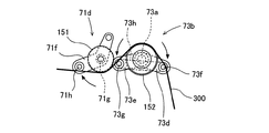
更に、移送部72が回転駆動されて初期状態から約165°回転すると、図13に示す如く、仮テープ300の先端部が第三位置P3まで移動される。かかる処理が実行されると、仮テープ300は、移送部72によりテープフィーダ100の第一テープ保持部133に対応する位置まで引き出されたことになる。そして、仮テープ300は、移送により張られた仮テープ300の一部が第一押出部73により更に押し出されつつ、カバーテープ220の排出経路に倣った経路に沿った形状に配策されて成形される。 Further, when the transfer portion 72 is rotationally driven and rotated by about 165 ° from the initial state, the tip portion of the temporary tape 300 is moved to the third position P3 as shown in FIG. When such a process is executed, the temporary tape 300 is pulled out by the transfer unit 72 to a position corresponding to the first tape holding unit 133 of the tape feeder 100. Then, the temporary tape 300 is formed by arranging a part of the temporary tape 300 stretched by the transfer into a shape along a path following the discharge path of the cover tape 220 while being further extruded by the first extrusion portion 73. Will be done.

より具体的には、本体プレート71の外側支持ピン機構部71d及び第一押出部73の内側支持ピン機構部73bにより、仮テープ300は、S字状に湾曲した形状に成形される。このとき、内側支持ピン機構部73bにおいては、各ピン73f,73gは、引張りばね73hにより初期間隔に維持されている。そして、移送部72が初期状態から約165°回転した状態において、図13に示す如く、仮テープ300は、移送により張られた仮テープ300の一部が第二押出部74の案内ピン74bにより押し出されつつ、後にカバーテープ220と連結される際にそのカバーテープ220と対向するように、U字状に成形される。このように、仮テープ配策装置70は、移送部72を回転させることで第一押出部73及び第二押出部74を連動させ、仮テープ300を排出経路に倣った所定形状に成形してその所定形状の経路に沿って配策して保持する。 More specifically, the temporary tape 300 is formed into an S-shaped curved shape by the outer support pin mechanism portion 71d of the main body plate 71 and the inner support pin mechanism portion 73b of the first extrusion portion 73. At this time, in the inner support pin mechanism portion 73b, the pins 73f and 73g are maintained at the initial interval by the tension spring 73h. Then, in a state where the transfer unit 72 is rotated by about 165 ° from the initial state, as shown in FIG. 13, the temporary tape 300 is a part of the temporary tape 300 stretched by the transfer by the guide pin 74b of the second extrusion unit 74. While being extruded, it is formed into a U shape so as to face the cover tape 220 when it is later connected to the cover tape 220. In this way, the temporary tape distribution device 70 links the first extrusion unit 73 and the second extrusion unit 74 by rotating the transfer unit 72, and forms the temporary tape 300 into a predetermined shape following the discharge path. Arrange and hold along the path of the predetermined shape.

カバーテープ把持装置75は、ベーステープ210から剥離されたカバーテープ220の先端を把持する装置である。カバーテープ把持装置75は、台座61に固定された仮テープ配策装置70の本体プレート71に取り付けられている。尚、カバーテープ把持装置75は、台座34に固定された第二テープ搬送装置30側に取り付けられるものとし、把持が要求される時に直交方向Yへ前進されるものとしてもよい。 The cover tape gripping device 75 is a device that grips the tip of the cover tape 220 peeled off from the base tape 210. The cover tape gripping device 75 is attached to the main body plate 71 of the temporary tape distribution device 70 fixed to the pedestal 61. The cover tape gripping device 75 may be attached to the second tape transporting device 30 side fixed to the pedestal 34, and may be advanced in the orthogonal direction Y when gripping is required.

カバーテープ把持装置75は、下部材76と、上部材77と、を有している。下部材76及び上部材77はそれぞれ、ベーステープ210から剥離されたカバーテープ220を把持可能なブロック状に形成されている。下部材76は、カバーテープ把持装置75の下部に配置されている。上部材77は、カバーテープ把持装置75の上部に配置されており、下部材76の上方に配置されている。下部材76及び上部材77は、互いに離接可能に構成されている。下部材76と上部材77とは、上下方向Zに相対移動することが可能である。下部材76と上部材77とは、カバーテープ220の把持前は互いに離間し、その把持が要求された時に互いに当接される。 The cover tape gripping device 75 includes a lower member 76 and an upper member 77. The lower member 76 and the upper member 77 are each formed in a block shape capable of gripping the cover tape 220 peeled off from the base tape 210. The lower member 76 is arranged below the cover tape gripping device 75. The upper member 77 is arranged above the cover tape gripping device 75, and is arranged above the lower member 76. The lower member 76 and the upper member 77 are configured to be detachable from each other. The lower member 76 and the upper member 77 can move relative to each other in the vertical direction Z. The lower member 76 and the upper member 77 are separated from each other before the cover tape 220 is gripped, and are brought into contact with each other when the gripping is required.

また、カバーテープ把持装置75は、本体プレート71に直交方向Yへ進退可能に装着されている。カバーテープ把持装置75の本体プレート71に対する装着位置は、互いに離間した下部材76と上部材77との間に、テープフィーダ100の第一テープ保持部133から搬送方向X側に突出したカバーテープ220の先端部が進入可能な位置である。カバーテープ把持装置75は、制御により直交方向Yへ進退することが可能である。カバーテープ把持装置75は、カバーテープ220の把持前は第二押出部74の回転を妨げないように後退されており、その把持が要求された時に把持可能に前進される。下部材76及び上部材77は、直交方向Yへの前進が完了するまでは互いに離間しており、その前進が完了した後に互いに当接される。かかる当接がなされると、その下部材76と上部材77との間にカバーテープ220の先端部が挟まれて把持される。 Further, the cover tape gripping device 75 is attached to the main body plate 71 so as to be able to advance and retreat in the orthogonal direction Y. The mounting position of the cover tape gripping device 75 with respect to the main body plate 71 is such that the cover tape 220 projecting from the first tape holding portion 133 of the tape feeder 100 to the transport direction X side between the lower member 76 and the upper member 77 separated from each other. It is a position where the tip of the can enter. The cover tape gripping device 75 can move forward and backward in the orthogonal direction Y by control. Before gripping the cover tape 220, the cover tape gripping device 75 is retracted so as not to hinder the rotation of the second extruded portion 74, and is advanced so as to be grippable when the gripping is requested. The lower member 76 and the upper member 77 are separated from each other until the advance in the orthogonal direction Y is completed, and are brought into contact with each other after the advance is completed. When such contact is made, the tip end portion of the cover tape 220 is sandwiched and gripped between the lower member 76 and the upper member 77.

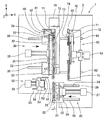
連結装置80は、仮テープ配策装置70により上記の如く保持されている仮テープ300を、テープフィーダ100の第一テープ保持部133においてキャリアテープ200のベーステープ210から剥離されたカバーテープ220の先端側に連結する装置である。この連結は、カバーテープ220と仮テープ300とを加熱接着により実現される。そして、この加熱接着は、カバーテープ220と仮テープ300との接着箇所のテープ長手方向の中途に折り目が形成されるように行われる。 The connecting device 80 is a cover tape 220 in which the temporary tape 300 held by the temporary tape arrangement device 70 as described above is peeled off from the base tape 210 of the carrier tape 200 at the first tape holding portion 133 of the tape feeder 100. It is a device that connects to the tip side. This connection is realized by heat-bonding the cover tape 220 and the temporary tape 300. Then, this heat bonding is performed so that a crease is formed in the middle of the tape longitudinal direction at the bonding portion between the cover tape 220 and the temporary tape 300.

連結装置80は、台座61に固定された仮テープ配策装置70の本体プレート71に取り付けられている。連結装置80は、テープ支持部材81と、加熱部材82と、を有している。尚、連結装置80のテープ支持部材81及び加熱部材82のうち少なくとも何れか一方は、上記の本体プレート71に代えて、台座34に固定された第二テープ搬送装置30側に取り付けられるものとしてもよい。この場合は、第二テープ搬送装置30側に取り付けられた連結装置80は、連結が要求された時に直交方向Yへ前進されるものとしてもよい。 The connecting device 80 is attached to the main body plate 71 of the temporary tape distribution device 70 fixed to the pedestal 61. The connecting device 80 includes a tape support member 81 and a heating member 82. It should be noted that at least one of the tape support member 81 and the heating member 82 of the coupling device 80 may be attached to the second tape transfer device 30 side fixed to the pedestal 34 instead of the main body plate 71. Good. In this case, the connecting device 80 attached to the second tape transporting device 30 side may be advanced in the orthogonal direction Y when the connection is requested.

テープ支持部材81は、カバーテープ220と仮テープ300との連結時に両テープ220,300の先端部同士を互いに重ねた状態で支持するテープ押さえである。テープ支持部材81は、矩形ブロック状に形成された部材である。テープ支持部材81は、本体プレート71に直交方向Yへ進退可能に装着されている。テープ支持部材81の本体プレート71に対する装着位置は、仮テープ配策装置70によりU字状に成形された仮テープ300のU字部の内側にあり、かつ、テープフィーダ100の第一テープ保持部133から搬送方向X側に突出したカバーテープ220の先端部の上方にある。テープ支持部材81は、制御により直交方向Yへ進退することが可能である。テープ支持部材81は、仮テープ配策装置70が仮テープ300を所定経路に沿った状態に保持する前は第二押出部74の回転を妨げないように後退されており、仮テープ配策装置70による仮テープ300の保持後にテープ220,300を支持可能に前進される。 The tape support member 81 is a tape holder that supports the cover tape 220 and the temporary tape 300 in a state where the tips of the tapes 220 and 300 are overlapped with each other when the cover tape 220 and the temporary tape 300 are connected. The tape support member 81 is a member formed in a rectangular block shape. The tape support member 81 is attached to the main body plate 71 so as to be able to advance and retreat in the orthogonal direction Y. The mounting position of the tape support member 81 with respect to the main body plate 71 is inside the U-shaped portion of the temporary tape 300 formed in a U-shape by the temporary tape distribution device 70, and the first tape holding portion of the tape feeder 100. It is above the tip of the cover tape 220 protruding from 133 toward the X side in the transport direction. The tape support member 81 can move forward and backward in the orthogonal direction Y by control. The tape support member 81 is retracted so as not to hinder the rotation of the second extrusion portion 74 before the temporary tape distribution device 70 holds the temporary tape 300 in a state along a predetermined path, and the temporary tape distribution device 81 is retracted so as not to hinder the rotation of the second extrusion portion 74. After the temporary tape 300 is held by 70, the tapes 220 and 300 are advanced so as to be supportable.

テープ支持部材81は、金属部81aと、樹脂部81bと、を有している。金属部81aは、テープ支持部材81の上部に配置されている。樹脂部81bは、テープ支持部材81の下部に配置されており、金属部81aの下面に固定されている。テープ支持部材81は、樹脂部81bの下面にてカバーテープ220の先端部と仮テープ300の先端部とを互いに重ねた状態で支持する。樹脂部81bは、下面が搬送方向Xにかけて屈曲するように形成されている。具体的には、樹脂部81bは、図14及び図15に示す如く、下面にて谷折り角部81eを挟んで二面が形成される谷形状を有している。 The tape support member 81 has a metal portion 81a and a resin portion 81b. The metal portion 81a is arranged above the tape support member 81. The resin portion 81b is arranged below the tape support member 81 and is fixed to the lower surface of the metal portion 81a. The tape support member 81 is supported on the lower surface of the resin portion 81b with the tip of the cover tape 220 and the tip of the temporary tape 300 overlapping each other. The resin portion 81b is formed so that the lower surface is bent in the transport direction X. Specifically, as shown in FIGS. 14 and 15, the resin portion 81b has a valley shape in which two surfaces are formed with the valley fold angle portion 81e sandwiched on the lower surface.

すなわち、樹脂部81bの下面は、水平部81cと、斜面部81dと、谷折り角部81eと、を有している。水平部81cは、略水平に広がる下方に向いた下面である。斜面部81dは、水平部81cに対して後方に隣接する斜め下方に向いた下面である。谷折り角部81eは、水平部81cと斜面部81dとの間において直交方向Yに直線状に延びるように形成されている。樹脂部81bは、谷折り角部81eで水平部81cと斜面部81dとが樹脂部81bの本体側を介してなす角度αが例えば約230°などの180°を超えるように形成されている。 That is, the lower surface of the resin portion 81b has a horizontal portion 81c, a slope portion 81d, and a valley fold angle portion 81e. The horizontal portion 81c is a lower surface facing downward that spreads substantially horizontally. The slope portion 81d is a lower surface facing diagonally downward adjacent to the horizontal portion 81c rearward. The valley fold angle portion 81e is formed so as to extend linearly in the orthogonal direction Y between the horizontal portion 81c and the slope portion 81d. The resin portion 81b is formed so that the angle α formed by the horizontal portion 81c and the slope portion 81d at the valley fold angle portion 81e via the main body side of the resin portion 81b exceeds 180 °, for example, about 230 °.

加熱部材82は、テープ支持部材81との間でカバーテープ220の先端部と仮テープ300の先端部とを挟み込むことによりカバーテープ220と仮テープ300とを加熱接着する部材である。加熱部材82は、アーム状に形成された部材である。加熱部材82は、本体プレート71に上下方向Z(具体的には、斜め上下方向)へ上下動可能に装着されている。加熱部材82は、仮テープ配策装置70の第二押出部74の回転位置に対して重なるように本体プレート71に配置されている。この配置位置は、テープ支持部材81の前進位置でそのテープ支持部材81に重なる位置である。加熱部材82は、制御により斜め上下方向へ、前進位置にあるテープ支持部材81と離接可能に移動することが可能である。加熱部材82は、上記の加熱接着前は下方に位置しており、その加熱接着が要求された時に斜め上方へその上面がテープ支持部材81の下面に当接するまで移動される。 The heating member 82 is a member that heat-bonds the cover tape 220 and the temporary tape 300 by sandwiching the tip of the cover tape 220 and the tip of the temporary tape 300 between the tape support member 81. The heating member 82 is a member formed in an arm shape. The heating member 82 is mounted on the main body plate 71 so as to be vertically movable in the vertical direction Z (specifically, in the oblique vertical direction). The heating member 82 is arranged on the main body plate 71 so as to overlap with the rotation position of the second extrusion portion 74 of the temporary tape distribution device 70. This arrangement position is a position where the tape support member 81 is advanced and overlaps the tape support member 81. The heating member 82 can be moved in an obliquely vertical direction by control so as to be detachable from the tape support member 81 in the forward position. The heating member 82 is located below before the heat bonding, and is moved diagonally upward until the upper surface of the heating member 82 abuts on the lower surface of the tape supporting member 81 when the heat bonding is required.

加熱部材82は、テープ支持部材81の下面に合致した上面を有している。加熱部材82は、上面にてテープ支持部材81の下面との間でカバーテープ220の先端部と仮テープ300の先端部とを互いに重ねた状態で挟み込むことが可能である。加熱部材82は、制御により上面部が所定温度(例えば170℃)まで昇温されることが可能である。加熱部材82は、上面が搬送方向Xにかけて屈曲するように形成されている。具体的には、加熱部材82は、上面にて山折り角部82cを挟んで二面が形成される山形状を有している。 The heating member 82 has an upper surface that matches the lower surface of the tape support member 81. The heating member 82 can sandwich the tip of the cover tape 220 and the tip of the temporary tape 300 in a state of being overlapped with each other on the upper surface of the cover tape 220 with the lower surface of the tape support member 81. The upper surface of the heating member 82 can be raised to a predetermined temperature (for example, 170 ° C.) by control. The heating member 82 is formed so that the upper surface is bent in the transport direction X. Specifically, the heating member 82 has a mountain shape in which two surfaces are formed with the mountain fold angle portion 82c sandwiched on the upper surface.

すなわち、加熱部材82の上面は、水平部82aと、斜面部82bと、山折り角部82cと、を有している。水平部82aは、略水平に広がる上方に向いた上面である。斜面部82bは、水平部82aに対して後方に隣接する斜め上方に向いた上面である。斜面部82bは、テープ支持部材81の斜面部81dに対応するように形成されている。山折り角部82cは、水平部82aと斜面部82bとの間において直交方向Yに直線状に延びるよいに形成されている。加熱部材82は、山折り角部82cで水平部82aと斜面部82bとが加熱部材82の本体側を介してなす角度βが例えば約130°などの180°を下回るように形成されている。この角度βは、上記の樹脂部81bの角度αとの間で合計角度(α+β)が360°となるように設定されている。 That is, the upper surface of the heating member 82 has a horizontal portion 82a, a slope portion 82b, and a mountain fold angle portion 82c. The horizontal portion 82a is an upper surface facing upward that spreads substantially horizontally. The slope portion 82b is an upper surface facing diagonally upward adjacent to the horizontal portion 82a rearward. The slope portion 82b is formed so as to correspond to the slope portion 81d of the tape support member 81. The mountain fold angle portion 82c is formed so as to extend linearly in the orthogonal direction Y between the horizontal portion 82a and the slope portion 82b. The heating member 82 is formed so that the angle β formed by the horizontal portion 82a and the slope portion 82b at the mountain fold angle portion 82c via the main body side of the heating member 82 is less than 180 °, for example, about 130 °. This angle β is set so that the total angle (α + β) with respect to the angle α of the resin portion 81b is 360 °.

上記した加熱部材82が加熱接着要求時にテープ支持部材81の下面に当接するまで移動される斜め上方の方向は、テープ支持部材81の谷折り角部81eの角度α及び加熱部材82の山折り角部82cの角度βそれぞれを二等分する方向である。すなわち、加熱部材82は、テープ支持部材81との間でカバーテープ220と仮テープ300との加熱接着を行ううえで、上記の角度α及び角度βそれぞれを二等分する方向へ移動される。 The diagonally upward direction in which the heating member 82 is moved until it comes into contact with the lower surface of the tape support member 81 at the time of requesting heat bonding is the angle α of the valley fold angle portion 81e of the tape support member 81 and the mountain fold angle of the heating member 82. This is the direction in which each of the angles β of the portion 82c is bisected. That is, the heating member 82 is moved in the direction of bisecting each of the above angles α and β in order to heat-bond the cover tape 220 and the temporary tape 300 between the tape support member 81 and the cover tape 220.

移載装置90は、カバーテープ220の先端部に連結されている仮テープ300を仮テープ配策装置70からテープフィーダ100へ移載する装置である。移載装置90は、仮テープ配策装置70の動作及び第二開放装置50の動作を制御して仮テープ300の移載処理を行う。 The transfer device 90 is a device for transferring the temporary tape 300 connected to the tip of the cover tape 220 from the temporary tape distribution device 70 to the tape feeder 100. The transfer device 90 controls the operation of the temporary tape distribution device 70 and the operation of the second opening device 50 to perform the transfer process of the temporary tape 300.

次に、図16−図24を用いて、テープ自動装填装置1の動作について説明する。
テープ自動装填装置1において、初期状態では、図1に示すように、第一テープ搬送装置20及び第二テープ搬送装置30、第一開放装置40及び第二開放装置50、並びにカバーテープ処理装置60の何れも、フィーダ保持台10から直交方向Yに所定距離をもって離間している。また、カバーテープ処理装置60の仮テープ配策装置70は、上記した動作により予め、仮テープ300をカバーテープ220の排出経路に倣った経路に沿った形状に成形して保持している。尚、仮テープ配策装置70による仮テープ300の成形乃至保持は、連結装置80によるカバーテープ220との連結までに行われていればよく、例えば、テープフィーダ100によるキャリアテープ200の搬送と同時に行われてもよい。
Next, the operation of the tape automatic loading device 1 will be described with reference to FIGS. 16 to 24.
In the tape automatic loading device 1, in the initial state, as shown in FIG. 1, the first tape transfer device 20, the second tape transfer device 30, the first release device 40 and the second release device 50, and the cover tape processing device 60 All of the above are separated from the feeder holding table 10 in the orthogonal direction Y at a predetermined distance. Further, the temporary tape distribution device 70 of the cover tape processing device 60 holds the temporary tape 300 formed in advance in a shape along a path following the discharge path of the cover tape 220 by the above operation. The temporary tape 300 may be formed or held by the temporary tape distribution device 70 until it is connected to the cover tape 220 by the connecting device 80. For example, at the same time as the carrier tape 200 is conveyed by the tape feeder 100. It may be done.

上記の初期状態において、作業者は、テープフィーダ100をフィーダ保持台10にセットする。具体的には、フィーダ本体110の底面を載置部11上の一対の支持ガイド13間に載置して挟持させ、フィーダ本体110の位置決めピン及び通信コネクタを当接部12の位置決め部15及び通信ジャック14にそれぞれ差し込む。そして、テープリール240をリール収容部120に取り付け、テープ自動装填装置1の制御装置として設けられているフィーダセット完了ボタンを押す。 In the above initial state, the operator sets the tape feeder 100 on the feeder holding table 10. Specifically, the bottom surface of the feeder main body 110 is placed between the pair of support guides 13 on the mounting portion 11 and sandwiched, and the positioning pin and communication connector of the feeder main body 110 are placed on the positioning portion 15 of the contact portion 12 and the communication connector. Plug each into the communication jack 14. Then, the tape reel 240 is attached to the reel accommodating portion 120, and the feeder set completion button provided as the control device of the tape automatic loading device 1 is pressed.

かかるフィーダセット完了ボタンが押下されると、第一テープ搬送装置20及び第二テープ搬送装置30それぞれが制御によりフィーダ保持台10に接近する直交方向Yにスライドされる。そして、図16に示す如く、第一テープ搬送装置20及び第二テープ搬送装置30それぞれが、ガイド21,31の直交方向Yの位置がテープフィーダ100のテープ送りガイド111の直交方向Yの位置と等しくなるように位置決めされる。 When the feeder set completion button is pressed, each of the first tape transfer device 20 and the second tape transfer device 30 is controlledly slid in the orthogonal direction Y approaching the feeder holding base 10. Then, as shown in FIG. 16, in each of the first tape transfer device 20 and the second tape transfer device 30, the position of the guides 21 and 31 in the orthogonal direction Y is the position of the tape feeder 100 in the orthogonal direction Y. Positioned to be equal.

また、第二テープ搬送装置30の上記したスライド移動に伴い第一開放装置40がスライドされる。この場合には、第一開放装置40の第一リフトレバー41がテープフィーダ100の第一テープ保持部133のレバー138に対して作動許容側に差し込まれる。そして、第一開放装置40の支持台42が制御により上下方向Zに上昇されると、第一リフトレバー41が第一テープ保持部133のレバー138を持ち上げる。レバー138が持ち上げられると、第一テープ保持部133が回転支点133aを中心に上方へ回転するので、その第一テープ保持部133とスプロケット131との間の保持状態が解除される。 Further, the first opening device 40 is slid along with the above-mentioned slide movement of the second tape conveying device 30. In this case, the first lift lever 41 of the first opening device 40 is inserted into the operation allowable side with respect to the lever 138 of the first tape holding portion 133 of the tape feeder 100. Then, when the support base 42 of the first opening device 40 is raised in the vertical direction Z by control, the first lift lever 41 lifts the lever 138 of the first tape holding portion 133. When the lever 138 is lifted, the first tape holding portion 133 rotates upward about the rotation fulcrum 133a, so that the holding state between the first tape holding portion 133 and the sprocket 131 is released.

ここで、作業者は、リール収容部120に収容されたテープリール240からキャリアテープ200を引き出し、そのキャリアテープ200の先端部(具体的には、カバーテープ220の先端部)を第一テープ搬送装置20のガイド21の後端部に差し込む。かかる差込が行われると、図示しないセンサによりカバーテープ220の先端部が検出された後、各ギヤモータ24,33及びモータ132が駆動される。かかるモータ24,33,132が駆動されると、キャリアテープ200が、搬送方向Xへ送り出されてガイド21,31及びテープ送りガイド111により案内され、第一テープ保持部133とスプロケット131との間隙を通過する位置まで搬送される。 Here, the operator pulls out the carrier tape 200 from the tape reel 240 housed in the reel accommodating portion 120, and conveys the tip end portion of the carrier tape 200 (specifically, the tip end portion of the cover tape 220) to the first tape. It is inserted into the rear end of the guide 21 of the device 20. When such insertion is performed, the gear motors 24 and 33 and the motor 132 are driven after the tip of the cover tape 220 is detected by a sensor (not shown). When the motors 24, 33, 132 are driven, the carrier tape 200 is fed in the transport direction X and guided by the guides 21, 31 and the tape feed guide 111, and the gap between the first tape holding portion 133 and the sprocket 131 is reached. It is transported to the position where it passes through.

キャリアテープ200が第一テープ保持部133まで搬送されると、各モータ24,33,132が駆動停止されると共に、第一開放装置40の支持台42及び第一リフトレバー41が制御により下降されて第一テープ保持部133のレバー138が下がる。レバー138が下がると、第一テープ保持部133が回転支点133aを中心に下方へ回転するので、その第一テープ保持部133とスプロケット131との間にキャリアテープ200が保持される状態になる。かかる状態でモータ132が駆動されると、スプロケット131が回転されることで、キャリアテープ200が、その先端部が所定量だけ第一テープ保持部133から搬送方向Xへ突出するように搬送される。 When the carrier tape 200 is conveyed to the first tape holding portion 133, the motors 24, 33, 132 are stopped, and the support base 42 and the first lift lever 41 of the first opening device 40 are lowered by control. The lever 138 of the first tape holding portion 133 is lowered. When the lever 138 is lowered, the first tape holding portion 133 rotates downward about the rotation fulcrum 133a, so that the carrier tape 200 is held between the first tape holding portion 133 and the sprocket 131. When the motor 132 is driven in such a state, the sprocket 131 is rotated, so that the carrier tape 200 is conveyed so that the tip portion thereof protrudes from the first tape holding portion 133 in the conveying direction X by a predetermined amount. ..

続いて、図17に示す如く、第一テープ搬送装置20及び第二テープ搬送装置30それぞれがフィーダ保持台10から離間する直交方向Yにスライドされる。更に、第二開放装置50がフィーダ保持台10に接近する直交方向Yにスライドされる。この場合には、第二開放装置50の第二リフトレバー51がテープフィーダ100の第二テープ保持部143のレバー146に対して作動許容側に差し込まれる。そして、第二開放装置50の支持台52が制御により搬送方向Xに移動されると、第二リフトレバー51により第二テープ保持部143のアーム145がフィーダ本体110の後端側において回転支点145aを中心にして回転される。この場合は、第二テープ保持部143のギヤ144がカバーテープ送り出し機構部140のギヤ141から離間するので、そのギヤ144とギヤ141との間の保持状態が解除される。 Subsequently, as shown in FIG. 17, each of the first tape transfer device 20 and the second tape transfer device 30 is slid in the orthogonal direction Y away from the feeder holding base 10. Further, the second opening device 50 is slid in the orthogonal direction Y approaching the feeder holding base 10. In this case, the second lift lever 51 of the second opening device 50 is inserted into the operation allowable side with respect to the lever 146 of the second tape holding portion 143 of the tape feeder 100. Then, when the support 52 of the second opening device 50 is moved in the transport direction X by control, the arm 145 of the second tape holding portion 143 is moved by the second lift lever 51 to the rotation fulcrum 145a on the rear end side of the feeder main body 110. It is rotated around. In this case, since the gear 144 of the second tape holding portion 143 is separated from the gear 141 of the cover tape feeding mechanism portion 140, the holding state between the gear 144 and the gear 141 is released.

カバーテープ送り出し機構部140のギヤ144とギヤ141とが開放されている状態で、カバーテープ処理装置60がフィーダ保持台10に接近する直交方向Yにスライドされる。この際、仮テープ配策装置70は、仮テープ300をカバーテープ220の排出経路に倣った経路に沿った形状に予め成形して保持している状態にある。そして、カバーテープ処理装置60が、仮テープ配策装置70にて保持している仮テープ300の直交方向Yの位置がテープフィーダ100に保持されているキャリアテープ200の直交方向Yの位置と等しくなるように位置決めされる。 With the gears 144 and 141 of the cover tape feeding mechanism unit 140 open, the cover tape processing device 60 is slid in the orthogonal direction Y approaching the feeder holding base 10. At this time, the temporary tape distribution device 70 is in a state in which the temporary tape 300 is preformed and held in a shape along the path following the discharge path of the cover tape 220. Then, the position of the temporary tape 300 held by the cover tape processing device 60 in the temporary tape distribution device 70 in the orthogonal direction Y is equal to the position of the carrier tape 200 held in the tape feeder 100 in the orthogonal direction Y. It is positioned so that

この位置決めは、図18に示す如く、テープフィーダ100の第一テープ保持部133から搬送方向X側に突出したカバーテープ220の先端部の下方に仮テープ300の先端部が位置して、カバーテープ220の先端部に仮テープ300の先端部が対向するように行われる。また、この位置決めは、テープフィーダ100の第一テープ保持部133から搬送方向X側に突出したカバーテープ220の先端部を挟んで上下にカバーテープ把持装置75の下部材76及び上部材77が対向して位置するように行われる。更に、仮テープ300のうち第一押出部73の二つの案内ピン73cの間に位置する部位は、離間したカバーテープ送り出し機構部140のギヤ141と第二テープ保持部143のギヤ144との間を通過するように位置決めされる。更に、仮テープ300のうち、外側支持ピン機構部71d及び内側支持ピン機構部73bによりS字状に湾曲した部位は、図20に示す如く、テープフィーダ100におけるカバーテープ送りガイド150の二つのガイドローラ151,152の間を通過するように位置決めされる。 In this positioning, as shown in FIG. 18, the tip of the temporary tape 300 is located below the tip of the cover tape 220 protruding from the first tape holding portion 133 of the tape feeder 100 in the transport direction X side, and the cover tape is positioned. The tip of the temporary tape 300 is opposed to the tip of the 220. Further, in this positioning, the lower member 76 and the upper member 77 of the cover tape gripping device 75 face each other up and down with the tip of the cover tape 220 protruding from the first tape holding portion 133 of the tape feeder 100 in the transport direction X side. It is done so that it is located. Further, the portion of the temporary tape 300 located between the two guide pins 73c of the first extrusion portion 73 is between the gear 141 of the cover tape feeding mechanism portion 140 and the gear 144 of the second tape holding portion 143. Is positioned to pass through. Further, in the temporary tape 300, the portions curved in an S shape by the outer support pin mechanism portion 71d and the inner support pin mechanism portion 73b are the two guides of the cover tape feed guide 150 in the tape feeder 100 as shown in FIG. It is positioned to pass between the rollers 151 and 152.

上記の位置決めがなされると、カバーテープ把持装置75の下部材76と上部材77とが互いに接近する方向に移動されることで、テープフィーダ100の第一テープ保持部133から搬送方向X側に突出したカバーテープ220の先端部が把持される。また、この把持前又は把持後において、連結装置80のテープ支持部材81が直交方向Yへテープ220,300を支持可能に前進される。そして、カバーテープ220の先端部が把持されかつテープ支持部材81が前進されると、加熱部材82がテープ支持部材81の下面に当接するまで斜め上方へ移動される。加熱部材82とテープ支持部材81とが互いに当接すると、カバーテープ220と仮テープ300とが互いに重なった状態で加熱部材82とテープ支持部材81との間で挟み込まれる。 When the above positioning is performed, the lower member 76 and the upper member 77 of the cover tape gripping device 75 are moved in a direction approaching each other, so that the tape feeder 100 moves from the first tape holding portion 133 to the transport direction X side. The tip of the protruding cover tape 220 is gripped. Further, before or after the gripping, the tape support member 81 of the connecting device 80 is advanced so as to support the tapes 220 and 300 in the orthogonal direction Y. Then, when the tip of the cover tape 220 is gripped and the tape support member 81 is advanced, the heating member 82 is moved diagonally upward until it comes into contact with the lower surface of the tape support member 81. When the heating member 82 and the tape support member 81 come into contact with each other, the cover tape 220 and the temporary tape 300 are sandwiched between the heating member 82 and the tape support member 81 in a state where they overlap each other.

加熱部材82が昇温された状態でカバーテープ220と仮テープ300とが加熱部材82とテープ支持部材81との間で挟み込まれると、そのカバーテープ220及び仮テープ300がその加熱部材82により加熱される。かかる加熱がなされると、カバーテープ220においてベーステープ210からの剥離時に剥離面に残存していた接着剤が加熱処理により軟化されて再度、接着剤として機能する。このため、カバーテープ220と仮テープ300とは、加熱部材82とテープ支持部材81とで挟み込まれた箇所にて接着剤により接着されて互いに連結される。 When the cover tape 220 and the temporary tape 300 are sandwiched between the heating member 82 and the tape support member 81 in a state where the heating member 82 has been heated, the cover tape 220 and the temporary tape 300 are heated by the heating member 82. Will be done. When such heating is performed, the adhesive remaining on the peeled surface of the cover tape 220 when peeled from the base tape 210 is softened by the heat treatment and functions as an adhesive again. Therefore, the cover tape 220 and the temporary tape 300 are adhered to each other by an adhesive at a portion sandwiched between the heating member 82 and the tape support member 81 and are connected to each other.

カバーテープ220と仮テープ300とが互いに連結されると、加熱部材82が斜め下方へ移動されてテープ支持部材81から離間すると共に、テープ支持部材81が直交方向Yへ後退される。更に、移送部72の把持爪72bによる仮テープ300の把持が解除される。そしてその後、仮テープ配策装置70が保持する仮テープ300がテープフィーダ100へ移載される。 When the cover tape 220 and the temporary tape 300 are connected to each other, the heating member 82 is moved diagonally downward to be separated from the tape support member 81, and the tape support member 81 is retracted in the orthogonal direction Y. Further, the temporary tape 300 is released from being gripped by the gripping claw 72b of the transfer unit 72. After that, the temporary tape 300 held by the temporary tape distribution device 70 is transferred to the tape feeder 100.

具体的には、上記した仮テープ300の移載は、まず、仮テープ配策装置70の移送部72が、初期状態から第三位置P3に到達するまでに回転した方向と同じ方向(図19における反時計回り方向)に更に回転されることにより行われる。かかる方向に移送部72が回転すると、移送部72の接触ローラ72fが第二押出部74の背面部から外れることで、その第二押出部74が弾性部材により逆方向(図19における時計回り方向)に回転されて初期状態に戻る。この際、仮テープ300は、連結されたカバーテープ220と一体となって、第一テープ保持部133を基点として180°折り返されて搬送方向Xの後方へ引かれつつ外側支持ピン機構部71dのピン71hによって支持される。その後、移載装置90は、仮テープリール310を、仮テープ300の引き出し方向とは逆方向(図19における時計回り方向)に回転させる。この回転により、第二押出部74が初期位置に戻るときに弛んだ仮テープ300が巻き取られる。 Specifically, the transfer of the temporary tape 300 described above is performed in the same direction as the direction in which the transfer unit 72 of the temporary tape distribution device 70 is rotated from the initial state until it reaches the third position P3 (FIG. 19). This is done by further rotating in the counterclockwise direction). When the transfer portion 72 rotates in this direction, the contact roller 72f of the transfer portion 72 is disengaged from the back surface portion of the second extrusion portion 74, so that the second extrusion portion 74 is moved in the opposite direction by the elastic member (clockwise direction in FIG. 19). ) To return to the initial state. At this time, the temporary tape 300 is integrated with the connected cover tape 220, is folded back 180 ° from the first tape holding portion 133 as a base point, and is pulled backward in the transport direction X while being pulled to the rear of the outer support pin mechanism portion 71d. Supported by pin 71h. After that, the transfer device 90 rotates the temporary tape reel 310 in a direction opposite to the drawing direction of the temporary tape 300 (clockwise in FIG. 19). Due to this rotation, the loose temporary tape 300 is wound up when the second extrusion portion 74 returns to the initial position.

更に、移載装置90が仮テープリール310を逆方向に回転させると、テープフィーダ100のテープ送り機構部130の停止中は仮テープ300の張力が増加する。仮テープ300の張力が増加すると、図21に示す如く、内側支持ピン機構部73bの引張りばね73hの弾性力に抗して二つのピン73f,73gが拡開しながら、仮テープ300がテープフィーダ100のガイドローラ152の両側を通過する。この場合、二つのピン73f,73gが保持していた仮テープ300がガイドローラ152に移載される。同様に、外側支持ピン機構部71dのピン71hがテープフィーダ100の先端側へ移動し、ピン71hが保持していた仮テープ300がテープフィーダ100のガイドローラ151に移載される。 Further, when the transfer device 90 rotates the temporary tape reel 310 in the opposite direction, the tension of the temporary tape 300 increases while the tape feed mechanism unit 130 of the tape feeder 100 is stopped. When the tension of the temporary tape 300 increases, as shown in FIG. 21, the temporary tape 300 spreads against the elastic force of the tension spring 73h of the inner support pin mechanism portion 73b while the temporary tape 300 expands to the tape feeder. It passes on both sides of the 100 guide rollers 152. In this case, the temporary tape 300 held by the two pins 73f and 73g is transferred to the guide roller 152. Similarly, the pin 71h of the outer support pin mechanism portion 71d moves to the tip end side of the tape feeder 100, and the temporary tape 300 held by the pin 71h is transferred to the guide roller 151 of the tape feeder 100.

仮テープ300がテープフィーダ100に移載されると、移載装置90が仮テープ300を保持させるように第二開放装置50を動作させる。かかる動作が行われると、第二開放装置50の支持台52がコイルバネ147の付勢力により搬送方向Xに移動されることで、第二テープ保持部143のアーム145がフィーダ本体110の前端側において回転支点145aを中心にして回転される。この場合は、第二テープ保持部143のギヤ144とカバーテープ送り出し機構部140のギヤ141との間に仮テープ300が保持される。 When the temporary tape 300 is transferred to the tape feeder 100, the transfer device 90 operates the second opening device 50 so as to hold the temporary tape 300. When such an operation is performed, the support 52 of the second opening device 50 is moved in the transport direction X by the urging force of the coil spring 147, so that the arm 145 of the second tape holding portion 143 is moved to the front end side of the feeder main body 110. It is rotated around the rotation fulcrum 145a. In this case, the temporary tape 300 is held between the gear 144 of the second tape holding portion 143 and the gear 141 of the cover tape feeding mechanism portion 140.

そして、カバーテープ処理装置60が、図示しないテープ切断機により、第二テープ保持部143と仮テープリール310との間で仮テープ300を切断する。この切断後、仮テープ300は、図6に示す如く、テープフィーダ100に移載された状態になる。尚、このとき、仮テープ300は、搬送途中のキャリアテープ200と干渉し得るが、キャリアテープ200を跨ぐようにフィーダ本体110内に設けられた切欠き部に係止されることで、キャリアテープ200との干渉を防止することが可能である。 Then, the cover tape processing device 60 cuts the temporary tape 300 between the second tape holding portion 143 and the temporary tape reel 310 by a tape cutting machine (not shown). After this cutting, the temporary tape 300 is in a state of being transferred to the tape feeder 100 as shown in FIG. At this time, the temporary tape 300 may interfere with the carrier tape 200 during transportation, but the carrier tape 300 is locked in the notch provided in the feeder main body 110 so as to straddle the carrier tape 200. It is possible to prevent interference with 200.

上記の切断後、カバーテープ処理装置60がフィーダ保持台10から離間する直交方向Yへ移動される。また、上記の切断後、移送部72が初期角度に戻される。更に、モータ132が駆動されてスプロケット131が回転されることで、ベーステープ210に収容されている部品が頭出しされ、部品吸着位置Lに位置決めされる。以上により、テープ自動装填装置1によるテープフィーダ100に対するキャリアテープ200の自動セットが終了される。 After the above cutting, the cover tape processing device 60 is moved in the orthogonal direction Y away from the feeder holding table 10. Further, after the above cutting, the transfer unit 72 is returned to the initial angle. Further, the motor 132 is driven to rotate the sprocket 131, so that the component housed in the base tape 210 is cueed and positioned at the component suction position L. As described above, the automatic setting of the carrier tape 200 with respect to the tape feeder 100 by the tape automatic loading device 1 is completed.

上記のテープ自動装填装置1においては、第一テープ搬送装置20及び第二テープ搬送装置30により、テープリール240を収容するリール収容部120からテープ送りガイド111を介してテープ送り機構部130までキャリアテープ200を搬送することができる。更に、カバーテープ処理装置60により、仮テープ300を上記のキャリアテープ200のカバーテープ220に加熱接着したうえでテープフィーダ100に移載することで、カバーテープ220を排出経路に沿ってフィーダ本体110の外方へ排出することができる。すなわち、カバーテープ処理装置60によれば、キャリアテープ200のカバーテープ220自体を直接的に排出経路に沿って配策することなく、仮テープ300を用いてカバーテープ220を第二テープ保持部143に保持させることができる。つまり、キャリアテープ200をテープフィーダ100に自動的に装填することができる。 In the above-mentioned automatic tape loading device 1, the carrier from the reel accommodating unit 120 accommodating the tape reel 240 to the tape feeding mechanism unit 130 via the tape feeding guide 111 by the first tape conveying device 20 and the second tape conveying device 30. The tape 200 can be conveyed. Further, the temporary tape 300 is heat-bonded to the cover tape 220 of the carrier tape 200 by the cover tape processing device 60 and then transferred to the tape feeder 100, whereby the cover tape 220 is transferred to the tape feeder 100, so that the cover tape 220 is transferred to the feeder main body 110 along the discharge path. Can be discharged to the outside of. That is, according to the cover tape processing device 60, the cover tape 220 itself of the carrier tape 200 is not arranged directly along the discharge path, and the cover tape 220 is transferred to the second tape holding portion 143 by using the temporary tape 300. Can be held by. That is, the carrier tape 200 can be automatically loaded into the tape feeder 100.

また、カバーテープ220を第二テープ保持部143に保持させるうえで、まず、仮テープ300をカバーテープ220の排出経路に倣った経路に沿って配策したうえでカバーテープ220の先端部に連結し、そして、その仮テープ300をテープフィーダ100に移載してカバーテープ220を間接的に排出経路に沿って配策する。従って、カバーテープ220を排出経路に沿って配策するうえで、キャリアテープ200からカバーテープ220を引き出す量として、仮テープ300と接着される箇所の長さ分があれば十分であって、あまり長くすることは不要であるので、キャリアテープ200側の部品をあまり無駄にすることなくテープフィーダ100にキャリアテープ200を装填することができる。 Further, in order to hold the cover tape 220 in the second tape holding portion 143, first, the temporary tape 300 is arranged along the path following the discharge path of the cover tape 220 and then connected to the tip portion of the cover tape 220. Then, the temporary tape 300 is transferred to the tape feeder 100, and the cover tape 220 is indirectly arranged along the discharge path. Therefore, in arranging the cover tape 220 along the discharge path, it is sufficient that the amount of the cover tape 220 to be pulled out from the carrier tape 200 is the length of the portion to be adhered to the temporary tape 300. Since it is not necessary to lengthen the carrier tape 200, the carrier tape 200 can be loaded into the tape feeder 100 without wasting much parts on the carrier tape 200 side.

また、連結装置80がカバーテープ220と仮テープ300とを加熱処理により互いに連結する。この連結は、ベーステープ210から剥離されたカバーテープ220の剥離面に残存していた接着剤を用いて行われる。すなわち、カバーテープ220が仮テープ300と加熱接着される面は、その剥離面である。このため、カバーテープ220と仮テープ300との連結を、別途の接着剤を用いることなく、剥離面に残存していた接着剤を再利用することで容易に実現することができる。 Further, the connecting device 80 connects the cover tape 220 and the temporary tape 300 to each other by heat treatment. This connection is performed using the adhesive remaining on the peeled surface of the cover tape 220 peeled from the base tape 210. That is, the surface on which the cover tape 220 is heat-bonded to the temporary tape 300 is the peeled surface. Therefore, the connection between the cover tape 220 and the temporary tape 300 can be easily realized by reusing the adhesive remaining on the peeled surface without using a separate adhesive.

更に、連結装置80によるカバーテープ220と仮テープ300との加熱接着は、それらのテープ220,300が互いに重なった箇所をテープ支持部材81と加熱部材82とが挟み込むことにより行われる。以下、カバーテープ220と仮テープ300とが挟み込まれて加熱接着された箇所を接着箇所Sと称す。この際、テープ220,300は、テープ支持部材81の下面と加熱部材82の上面との間で挟み込まれる。テープ支持部材81(具体的には、樹脂部81b)の下面は、谷折り角部81eを挟んで水平部81cと斜面部81dとが形成される谷形状に形成されている。また、加熱部材82の上面は、山折り角部82cを挟んで水平部82aと斜面部82bとが形成される山形状に形成されている。テープ支持部材81の谷形状と加熱部材82の山形状とは、互いに対応している。 Further, the heat bonding of the cover tape 220 and the temporary tape 300 by the connecting device 80 is performed by sandwiching the portion where the tapes 220 and 300 overlap each other between the tape support member 81 and the heating member 82. Hereinafter, the portion where the cover tape 220 and the temporary tape 300 are sandwiched and heat-bonded is referred to as an adhesion portion S. At this time, the tapes 220 and 300 are sandwiched between the lower surface of the tape support member 81 and the upper surface of the heating member 82. The lower surface of the tape support member 81 (specifically, the resin portion 81b) is formed in a valley shape in which the horizontal portion 81c and the slope portion 81d are formed with the valley folding angle portion 81e interposed therebetween. Further, the upper surface of the heating member 82 is formed in a mountain shape in which a horizontal portion 82a and a slope portion 82b are formed with the mountain folding angle portion 82c interposed therebetween. The valley shape of the tape support member 81 and the mountain shape of the heating member 82 correspond to each other.

テープ支持部材81と加熱部材82とは、カバーテープ220及び仮テープ300をテープ長手方向の中途において谷折り角部81e及び山折り角部82cに沿って折り曲げた状態で挟み込む。かかる挟み込みが行われると、カバーテープ220及び仮テープ300が互いに重なって接着された接着箇所Sのテープ長手方向の中途に、テープ短手方向に直線状に延びる折り目221,301が形成される。カバーテープ220及び仮テープ300それぞれにおける接着箇所Sの折り目221,301は、挟み込み時において上方へ突出する山折りとなる。 The tape support member 81 and the heating member 82 sandwich the cover tape 220 and the temporary tape 300 in a bent state along the valley fold angle portion 81e and the mountain fold angle portion 82c in the middle of the tape longitudinal direction. When such sandwiching is performed, folds 221, 301 extending linearly in the lateral direction of the tape are formed in the middle of the adhesive portion S where the cover tape 220 and the temporary tape 300 are overlapped and adhered to each other in the longitudinal direction of the tape. The folds 221, 301 of the adhesive points S in each of the cover tape 220 and the temporary tape 300 are mountain folds that project upward when sandwiched.

また、カバーテープ220及び仮テープ300の挟み込みが行われると、カバーテープ220における接着箇所Sよりも先端部に、非接着となる箇所(以下、先端側非接着部222と称す。)が残存すると共に、仮テープ300における接着箇所Sよりも先端側に、非接着となる箇所(以下、先端側非接着部302と称す。)が残存する。これらの先端側非接着部222,302は、上記の挟み込み時にカバーテープ220又は仮テープ300を把持するうえで必ず形成される。 Further, when the cover tape 220 and the temporary tape 300 are sandwiched, a non-adhesive portion (hereinafter, referred to as a tip-side non-adhesive portion 222) remains at the tip portion of the cover tape 220 rather than the adhesive portion S. At the same time, a non-adhesive portion (hereinafter, referred to as a tip-side non-adhesive portion 302) remains on the distal end side of the temporary tape 300 with respect to the adhesive portion S. These tip-side non-adhesive portions 222 and 302 are always formed for gripping the cover tape 220 or the temporary tape 300 at the time of the above-mentioned sandwiching.

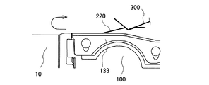
カバーテープ220が連結された仮テープ300がテープフィーダ100へ移載される過程では、図22に示す如く、その仮テープ300がカバーテープ220と一体となって、第一テープ保持部133を基点として180°折り返されて搬送方向Xの後方へ引かれる。かかる折り返しが行われると、カバーテープ220及び仮テープ300それぞれにおける接着箇所Sの折り目221,301は、下方へ突出する谷折りとなる。この際、図23に示す如く、カバーテープ220の先端側非接着部222は、後方へ引かれる仮テープ300の下方に位置してその仮テープ300に重ねられるので、その先端側非接着部222の上部が押さえられた状態になる。このため、カバーテープ220の先端側非接着部222が上方へ浮き上がることは防止される。 In the process of transferring the temporary tape 300 to which the cover tape 220 is connected to the tape feeder 100, as shown in FIG. 22, the temporary tape 300 is integrated with the cover tape 220 and uses the first tape holding portion 133 as a base point. It is folded back 180 ° and pulled backward in the transport direction X. When such folding is performed, the folds 221, 301 of the adhesive points S in each of the cover tape 220 and the temporary tape 300 become valley folds protruding downward. At this time, as shown in FIG. 23, the tip-side non-adhesive portion 222 of the cover tape 220 is located below the temporary tape 300 pulled backward and is overlapped with the temporary tape 300, so that the tip-side non-adhesive portion 222 is overlapped with the temporary tape 300. The upper part of is pressed. Therefore, it is prevented that the non-adhesive portion 222 on the tip end side of the cover tape 220 is lifted upward.

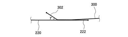
一方、仮テープ300の先端側非接着部302は、仮テープ300が後方に引かれる際にその上部を押さえる部材が存在しない。このため、仮に接着箇所Sのテープ長手方向の中途に折り目が形成されていないと、図24に示す如く、その先端側非接着部302が上方へ浮き上がってしまう。この浮き上がり量は、加熱接着当初のカバーテープ220と仮テープ300の先端部とがなす角度γが大きいほど大きくなる。 On the other hand, the non-adhesive portion 302 on the tip end side of the temporary tape 300 does not have a member that presses the upper portion of the temporary tape 300 when it is pulled backward. Therefore, if a crease is not formed in the middle of the adhesive portion S in the longitudinal direction of the tape, the non-adhesive portion 302 on the tip end side will rise upward as shown in FIG. 24. The amount of lifting increases as the angle γ formed by the tip of the cover tape 220 and the temporary tape 300 at the initial stage of heat bonding increases.

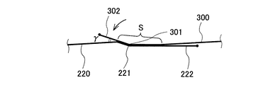
これに対して、本実施形態では、仮テープ300における接着箇所Sのテープ長手方向の中途に折り目301が形成されている。すなわち、カバーテープ220と仮テープ300との接着箇所Sが、テープ長手方向において折り目221,301を挟んだ両側の領域に及ぶ。かかる構造では、テープフィーダ100への仮テープ300の移載過程で仮テープ300がカバーテープ220と一体となって第一テープ保持部133を基点として180°折り返されて搬送方向Xの後方へ引かれる際、仮テープ300の張力により、その仮テープ300及びカバーテープ220の折り目301,221を挟んだテープ長手方向前後の接着箇所Sが、その折り目301,221が解消されるように延ばされる。 On the other hand, in the present embodiment, the crease 301 is formed in the middle of the adhesive portion S in the temporary tape 300 in the tape longitudinal direction. That is, the bonding portion S between the cover tape 220 and the temporary tape 300 extends to the regions on both sides of the folds 221, 301 in the longitudinal direction of the tape. In such a structure, in the process of transferring the temporary tape 300 to the tape feeder 100, the temporary tape 300 is integrated with the cover tape 220, folded back 180 ° with the first tape holding portion 133 as a base point, and pulled backward in the transport direction X. At the time of being squeezed, the tension of the temporary tape 300 extends the adhesive points S before and after the tape longitudinal direction sandwiching the folds 301 and 221 of the temporary tape 300 and the cover tape 220 so that the folds 301,221 are eliminated.

すなわち、仮テープ300が上記の如く後方へ引かれると、その張力が仮テープ300とカバーテープ220との接着箇所Sの全体に作用するので、カバーテープ220の接着箇所Sが、折り目221が解消されるようにそのテープ長手方向全域に亘って直線状に延ばされる。かかるカバーテープ220の接着箇所Sの引き延ばしが生じると、図23に示す如く、その引き延ばしに追従して、そのカバーテープ220と接着している仮テープ300の接着箇所Sが、折り目301が解消されるようにそのテープ長手方向全域に亘って直線状に延ばされる。この際、カバーテープ220と仮テープ300の先端部とがなす角度γは、加熱接着当初のものから小さくなる。 That is, when the temporary tape 300 is pulled backward as described above, the tension acts on the entire adhesive portion S between the temporary tape 300 and the cover tape 220, so that the adhesive portion S of the cover tape 220 is eliminated from the crease 221. It is stretched linearly over the entire longitudinal direction of the tape so as to be. When the adhesive portion S of the cover tape 220 is stretched, as shown in FIG. 23, the crease 301 is eliminated from the adhesive portion S of the temporary tape 300 that is adhered to the cover tape 220 following the stretch. As such, it is stretched linearly over the entire longitudinal direction of the tape. At this time, the angle γ formed by the cover tape 220 and the tip of the temporary tape 300 is smaller than that at the time of heat bonding.

従って、本実施形態によれば、加熱接着当初のカバーテープ220と仮テープ300とのなす角度が大きくても、仮テープ300における折り目301よりも先端側非接着部302を含む先端側を下げることができ、これにより、仮テープ300の先端側非接着部302が上方へ浮き上がること或いはその浮き上がり量が大きくなることを防止することができる。このため、仮テープ300の先端側非接着部302の過大な浮き上がりに起因する部品装着ヘッドとの干渉や部品の落下を抑えることができる。また、仮テープ300の浮き上がり防止を接着箇所Sに折り目を付けることにより実現する。このため、作業者の手作業(カット作業)などで仮テープ300の浮き上がり部を解消させることは不要であるので、作業性を大幅に向上させることが可能である。 Therefore, according to the present embodiment, even if the angle formed by the cover tape 220 and the temporary tape 300 at the initial stage of heat bonding is large, the tip side including the non-bonded portion 302 on the tip side is lowered from the crease 301 in the temporary tape 300. This makes it possible to prevent the non-adhesive portion 302 on the tip end side of the temporary tape 300 from rising upward or the amount of lifting thereof increases. Therefore, it is possible to suppress interference with the component mounting head and drop of the component due to excessive lifting of the non-adhesive portion 302 on the tip side of the temporary tape 300. Further, the temporary tape 300 is prevented from being lifted by making a crease in the adhesive portion S. Therefore, it is not necessary to eliminate the raised portion of the temporary tape 300 by the manual work (cutting work) of the operator, so that the workability can be significantly improved.

また、連結装置80によるカバーテープ220と仮テープ300との加熱接着は、加熱部材82が斜め上方へその上面がテープ支持部材81の下面に当接するまで移動されることによって行われる。この加熱部材82の移動は、テープ支持部材81との間でカバーテープ220と仮テープ300との加熱接着を行ううえで、テープ支持部材81の谷折り角部81eの角度α及び加熱部材82の山折り角部82cの角度βそれぞれを二等分する方向へ行われる。そして、加熱部材82の上面がテープ支持部材81の下面に当接することで、カバーテープ220及び仮テープ300が互いに重ねられた状態で折り目を付けられつつ互いに連結される。 Further, the heat bonding between the cover tape 220 and the temporary tape 300 by the connecting device 80 is performed by moving the heating member 82 diagonally upward until the upper surface thereof abuts on the lower surface of the tape support member 81. The movement of the heating member 82 is the angle α of the valley fold angle portion 81e of the tape support member 81 and the heating member 82 in order to heat-bond the cover tape 220 and the temporary tape 300 between the tape support member 81. The angle β of the mountain fold angle portion 82c is divided into two equal parts. Then, when the upper surface of the heating member 82 abuts on the lower surface of the tape support member 81, the cover tape 220 and the temporary tape 300 are connected to each other while being creases in a state where they are overlapped with each other.

この構成においては、連結装置80のテープ支持部材81と加熱部材82とが互いに当接した際、互いに重ねられたカバーテープ220及び仮テープ300が、テープ支持部材81の谷折り角部81e及び加熱部材82の山折り角部82cに挟み込まれる箇所を搬送方向Xの前後に挟んだ二面が均等な力で挟み込まれた状態になる。このため、カバーテープ220と仮テープ300との接着箇所Sに小さい力でも確実に折り目221,301を付けることができる。従って、それらの接着箇所Sの折り目221,301を所望形状に成形しつつ、その成形を行ううえで必要な構成をコンパクト化することができる。 In this configuration, when the tape support member 81 and the heating member 82 of the connecting device 80 come into contact with each other, the cover tape 220 and the temporary tape 300 that are overlapped with each other are heated at the valley fold angle portion 81e of the tape support member 81 and the heating member 81. The two surfaces sandwiched between the mountain fold corners 82c of the member 82 before and after the transport direction X are sandwiched by equal force. Therefore, the creases 221, 301 can be reliably formed at the bonding portion S between the cover tape 220 and the temporary tape 300 even with a small force. Therefore, while forming the folds 221, 301 of the bonding points S into a desired shape, it is possible to make the configuration required for the molding compact.

ところで、上記の実施形態においては、仮テープ300がカバーテープ220との連結後に浮き上がり得るものとしている。しかし、本開示はこれに限定されるものではない。カバー220が仮テープ300との連結後に浮き上がり得るものに適用することとしてもよい。 By the way, in the above embodiment, the temporary tape 300 can be lifted after being connected to the cover tape 220. However, the present disclosure is not limited to this. It may be applied to a cover 220 that can be lifted after being connected to the temporary tape 300.

また、上記の実施形態においては、加熱部材82が斜め上方に移動するものとしている。しかし、本開示はこれに限定されるものではない。加熱部材82とテープ支持部材81とが相対的に移動するものであればよく、テープ支持部材81が斜め下方へ移動するものに適用することとしてもよい。 Further, in the above embodiment, the heating member 82 is assumed to move diagonally upward. However, the present disclosure is not limited to this. The heating member 82 and the tape support member 81 may be relatively movable, and may be applied to a tape support member 81 that moves diagonally downward.

また、上記の実施形態においては、テープ支持部材81が連結装置80の上部に配置されかつ加熱部材82が連結装置80の下部に配置されるものとしている。しかし、本開示はこれに限定されるものではない。テープ支持部材81が連結装置80の下部に配置されかつ加熱部材82が連結装置80の上部に配置されるものに適用することとしてもよい。 Further, in the above embodiment, the tape support member 81 is arranged in the upper part of the connecting device 80, and the heating member 82 is arranged in the lower part of the connecting device 80. However, the present disclosure is not limited to this. It may be applied to the tape support member 81 arranged in the lower part of the connecting device 80 and the heating member 82 arranged in the upper part of the connecting device 80.

更に、上記の実施形態においては、テープ支持部材81が谷折り角部81eを有する谷形状に形成され、かつ、加熱部材82が山折り角部82cを有する山形状に形成されるものとしている。しかし、本開示はこれに限定されるものではない、逆に、テープ支持部材81が山折り角部を有する山形状に形成され、かつ、加熱部材82が谷折り角部を有する谷形状に形成されるものに適用することとしてもよい。 Further, in the above embodiment, the tape support member 81 is formed in a valley shape having a valley fold angle portion 81e, and the heating member 82 is formed in a mountain shape having a mountain fold angle portion 82c. However, the present disclosure is not limited to this, and conversely, the tape support member 81 is formed in a mountain shape having a mountain fold angle portion, and the heating member 82 is formed in a valley shape having a valley fold angle portion. It may be applied to what is done.

尚、本開示は、上述した実施形態や変形例に限定されるものではなく、本開示の趣旨を逸脱しない範囲で種々の変更を施すことが可能である。 The present disclosure is not limited to the above-described embodiments and modifications, and various modifications can be made without departing from the spirit of the present disclosure.

1:テープ自動装填装置、2:基台、10:フィーダ保持台、60:カバーテープ処理装置、70:仮テープ配策装置、75:カバーテープ把持装置、80:連結装置、81:テープ支持部材、81c:水平部、81d:斜面部、81e:谷折り角部、82:加熱部材、82a:水平部、82b:斜面部、82c:山折り角部、90:移載装置、100:テープフィーダ、200:キャリアテープ、210:ベーステープ、220:カバーテープ、300:仮テープ。 1: Automatic tape loading device, 2: Base, 10: Feeder holding base, 60: Cover tape processing device, 70: Temporary tape distribution device, 75: Cover tape gripping device, 80: Connecting device, 81: Tape support member , 81c: horizontal part, 81d: slope part, 81e: valley fold corner part, 82: heating member, 82a: horizontal part, 82b: slope part, 82c: mountain fold corner part, 90: transfer device, 100: tape feeder , 200: Carrier tape, 210: Base tape, 220: Cover tape, 300: Temporary tape.

Claims (5)

キャリアテープのベーステープからカバーテープを剥離すると共に、剥離された前記カバーテープを所定経路で排出するテープフィーダに、前記キャリアテープを装填するテープ自動装填装置であって、
仮テープを前記所定経路に倣った経路に沿って配策して保持する仮テープ配策装置と、
前記ベーステープから剥離された前記カバーテープの先端を把持するカバーテープ把持装置と、
前記カバーテープ把持装置に把持されている前記カバーテープの先端部に、前記仮テープ配策装置により保持されている前記仮テープを連結する連結装置と、
前記カバーテープの先端部に連結されている前記仮テープを前記仮テープ配策装置から前記テープフィーダへ移載する移載装置と、
を備え、
前記連結装置は、
前記カバーテープの先端部と前記仮テープとを互いに重ねた状態で支持するテープ支持部材と、
前記テープ支持部材との間に前記カバーテープの先端部と前記仮テープとが互いに重なった所定箇所を挟み込むことにより、前記カバーテープと前記仮テープとを加熱接着する加熱部材と、
を有し、
前記テープ支持部材及び前記加熱部材はそれぞれ、前記所定箇所をテープ長手方向の中途において折り曲げた状態で挟み込む形状を有している、テープ自動装填装置。
An automatic tape loading device for loading the carrier tape into a tape feeder that peels the cover tape from the base tape of the carrier tape and discharges the peeled cover tape by a predetermined route.
A temporary tape distribution device that arranges and holds the temporary tape along a route that follows the predetermined route, and
A cover tape gripping device that grips the tip of the cover tape that has been peeled off from the base tape,
A connecting device that connects the temporary tape held by the temporary tape distribution device to the tip of the cover tape that is gripped by the cover tape gripping device.
A transfer device for transferring the temporary tape connected to the tip of the cover tape from the temporary tape distribution device to the tape feeder, and a transfer device.
With
The connecting device is
A tape support member that supports the tip of the cover tape and the temporary tape in a state of being overlapped with each other.
A heating member that heat-bonds the cover tape and the temporary tape by sandwiching a predetermined portion where the tip end portion of the cover tape and the temporary tape overlap each other between the tape support member.
Have,
An automatic tape loading device having a shape in which the tape support member and the heating member each sandwich the predetermined portion in a bent state in the middle of the tape longitudinal direction.
前記加熱部材は、前記形状として、互いに対応する、山折り角部を挟んで二面が形成される山形状及び谷折り角部を挟んで二面が形成される谷形状のうち何れか一方を有し、
前記テープ支持部材は、前記形状として、前記山形状及び前記谷形状のうち何れか他方を有し、
前記テープ支持部材及び前記加熱部材は、前記仮テープにおける前記カバーテープとの接着箇所のテープ長手方向の中途に折り目が形成されるように加熱接着を行う、請求項1に記載のテープ自動装填装置。
The heating member has, as the shape, either a mountain shape in which two surfaces are formed across a mountain fold angle portion or a valley shape in which two surfaces are formed across a valley fold angle portion, which correspond to each other. Have and
The tape support member has either a mountain shape or a valley shape as the shape.
The automatic tape loading device according to claim 1, wherein the tape support member and the heating member are heat-bonded so that a crease is formed in the middle of the tape longitudinal direction at the bonding portion of the temporary tape with the cover tape. ..
前記テープ支持部材及び前記加熱部材は、前記カバーテープと前記仮テープとの加熱接着を行ううえで、前記山折り角部で二面がなす角度及び前記谷折り角部で二面がなす角度それぞれを二等分する方向へ相対移動される、請求項2に記載のテープ自動装填装置。 The tape support member and the heating member have an angle formed by two surfaces at the mountain fold angle portion and an angle formed by the two surfaces at the valley fold angle portion when the cover tape and the temporary tape are heat-bonded. The automatic tape loading device according to claim 2, wherein the tape is relatively moved in the direction of bisecting. 前記所定箇所は、前記移載装置が前記カバーテープを前記カバーテープ把持装置による把持が解除された後に後方へ引いたときに、テープ長手方向全域に亘って直線状に延びる、請求項1乃至3の何れか一項に記載のテープ自動装填装置。 Claims 1 to 3 wherein the predetermined portion extends linearly over the entire longitudinal direction of the tape when the transfer device pulls the cover tape backward after the cover tape is released from being gripped by the cover tape gripping device. The tape automatic loading device according to any one of the above. キャリアテープのベーステープからカバーテープを剥離すると共に、剥離された前記カバーテープを所定経路で排出するテープフィーダに、前記キャリアテープを装填するテープ自動装填装置において、カバーテープ把持装置に把持されている前記カバーテープの先端側に、仮テープ配策装置により前記所定経路に倣った経路に沿って配策されて保持されている仮テープを連結する方法であって、
テープ支持部材と加熱部材との間に、前記カバーテープの先端部と前記仮テープとが互いに重なった所定箇所をテープ長手方向の中途において折り曲げた状態で挟み込むことにより、前記カバーテープと前記仮テープとを加熱接着する、テープ自動装填装置のテープ連結方法。
The cover tape is peeled off from the base tape of the carrier tape, and the cover tape is gripped by the cover tape gripping device in the tape automatic loading device for loading the carrier tape into a tape feeder that discharges the peeled cover tape by a predetermined route. A method of connecting to the tip end side of the cover tape a temporary tape arranged and held along a route following the predetermined route by a temporary tape distribution device.
The cover tape and the temporary tape are sandwiched between the tape support member and the heating member by sandwiching a predetermined portion where the tip end portion of the cover tape and the temporary tape overlap each other in a bent state in the middle of the tape longitudinal direction. A tape connection method for an automatic tape loading device that heats and adheres to and.
JP2020507199A 2018-03-21 2018-03-21 Automatic tape loading device and its tape connection method Active JP6876868B2 (en)

Applications Claiming Priority (1)

Application Number Priority Date Filing Date Title
PCT/JP2018/011238 WO2019180858A1 (en) 2018-03-21 2018-03-21 Tape auto-loading device and tape linking method therefor

Publications (2)

Publication Number Publication Date
JPWO2019180858A1 JPWO2019180858A1 (en) 2020-12-03
JP6876868B2 true JP6876868B2 (en) 2021-05-26

Family

ID=67986873

Family Applications (1)

Application Number Title Priority Date Filing Date
JP2020507199A Active JP6876868B2 (en) 2018-03-21 2018-03-21 Automatic tape loading device and its tape connection method

Country Status (5)

Country Link
US (1) US11856704B2 (en)
EP (1) EP3771309B1 (en)
JP (1) JP6876868B2 (en)
CN (1) CN111788877B (en)
WO (1) WO2019180858A1 (en)

Families Citing this family (2)

* Cited by examiner, † Cited by third party
Publication number Priority date Publication date Assignee Title
TWI747579B (en) * 2020-10-27 2021-11-21 潤勝科技有限公司 Semi-automatic tape feeding machine
CN118592103A (en) * 2022-02-07 2024-09-03 株式会社富士 Reel loading device

Family Cites Families (12)

* Cited by examiner, † Cited by third party
Publication number Priority date Publication date Assignee Title
JP3197370B2 (en) * 1992-11-26 2001-08-13 ローム株式会社 Continuous taping device for electronic components
JP3569004B2 (en) 1994-10-17 2004-09-22 日本テトラパック株式会社 Film bonding equipment
JPH1187991A (en) * 1997-09-10 1999-03-30 Toshiba Fa Syst Eng Kk Automatic arranger for chip-type taping
TW557282B (en) * 2001-08-08 2003-10-11 Oji Paper Co Base board for electronical chip-container board and container board using same
JP4460935B2 (en) * 2004-04-02 2010-05-12 東芝モバイルディスプレイ株式会社 Manufacturing method of electronic / electrical products such as flat display devices, and belt-like storage body therefor
US7875138B2 (en) 2007-10-03 2011-01-25 Panasonic Corporation Adhesive tape applying apparatus and tape splicing method
JP5703672B2 (en) * 2010-10-05 2015-04-22 日東紡績株式会社 Non-combustible sheet joint
JP2013157349A (en) * 2012-01-26 2013-08-15 Murata Mfg Co Ltd Tape feeder, method of using tape feeder and take-up reel
US9736970B2 (en) * 2012-03-06 2017-08-15 Fuji Machine Mfg. Co., Ltd. Automatic tape setting apparatus
CN104365189B (en) * 2012-06-11 2017-03-08 富士机械制造株式会社 Cover tape filler device and band arrange device automatically
JP6053824B2 (en) 2012-12-21 2016-12-27 富士機械製造株式会社 Tape automatic processing device and tape automatic setting device
CN207869599U (en) * 2018-03-16 2018-09-14 深圳市华安半导体有限公司东莞分公司 A kind of feeder equipped with protective film mechanism for stripping

Also Published As

Publication number Publication date
EP3771309B1 (en) 2023-03-15
JPWO2019180858A1 (en) 2020-12-03
CN111788877A (en) 2020-10-16
US11856704B2 (en) 2023-12-26
EP3771309A1 (en) 2021-01-27
WO2019180858A1 (en) 2019-09-26
US20210007252A1 (en) 2021-01-07
CN111788877B (en) 2021-07-16
EP3771309A4 (en) 2021-03-31

Similar Documents

Publication Publication Date Title
JP6920546B2 (en) Tape autoloader
JP7158176B2 (en) Automatic tape loading device
US10772247B2 (en) Tape cutting processing apparatus and processing method
JP5877891B2 (en) Tape automatic setting device
JP6053824B2 (en) Tape automatic processing device and tape automatic setting device
JP6876868B2 (en) Automatic tape loading device and its tape connection method
JP5955384B2 (en) Top tape loading device and tape automatic setting device
CN111356642B (en) Bundling and packaging device
JP7350879B2 (en) Tape automatic loading system
JP7481506B2 (en) Tape Loader
JP7136589B2 (en) TAPE LOADING DEVICE AND TAPE CONNECTING METHOD
KR20120051568A (en) Electric tape cutter
JP4028411B2 (en) Packing method and apparatus for rolls
WO2018008115A1 (en) Feeder
TW201708049A (en) Medicine packing apparatus
JP6534049B2 (en) Parts supply device
JP5559735B2 (en) Parts supply device
JP6950057B2 (en) feeder
JP6678416B2 (en) feeder
JP2000203528A (en) Sealing device

Legal Events

Date Code Title Description
A621 Written request for application examination

Free format text: JAPANESE INTERMEDIATE CODE: A621

Effective date: 20200610

TRDD Decision of grant or rejection written
A01 Written decision to grant a patent or to grant a registration (utility model)

Free format text: JAPANESE INTERMEDIATE CODE: A01

Effective date: 20210420

A61 First payment of annual fees (during grant procedure)

Free format text: JAPANESE INTERMEDIATE CODE: A61

Effective date: 20210426

R150 Certificate of patent or registration of utility model

Ref document number: 6876868

Country of ref document: JP

Free format text: JAPANESE INTERMEDIATE CODE

Ref document number: 6876868

Country of ref document: JP

Free format text: JAPANESE INTERMEDIATE CODE: R150

R250 Receipt of annual fees

Free format text: JAPANESE INTERMEDIATE CODE: R250