JP6534049B2 - Parts supply device - Google Patents

Parts supply device Download PDF

Info

Publication number
JP6534049B2
JP6534049B2 JP2017225927A JP2017225927A JP6534049B2 JP 6534049 B2 JP6534049 B2 JP 6534049B2 JP 2017225927 A JP2017225927 A JP 2017225927A JP 2017225927 A JP2017225927 A JP 2017225927A JP 6534049 B2 JP6534049 B2 JP 6534049B2
Authority
JP
Japan
Prior art keywords
tape
carrier tape
carrier
path
feeding
Prior art date
Legal status (The legal status is an assumption and is not a legal conclusion. Google has not performed a legal analysis and makes no representation as to the accuracy of the status listed.)
Active
Application number
JP2017225927A
Other languages
Japanese (ja)
Other versions
JP2018050071A (en
Inventor
元寛 樋口
元寛 樋口
実 木谷
実 木谷
Current Assignee (The listed assignees may be inaccurate. Google has not performed a legal analysis and makes no representation or warranty as to the accuracy of the list.)
Panasonic Intellectual Property Management Co Ltd
Original Assignee
Panasonic Intellectual Property Management Co Ltd
Priority date (The priority date is an assumption and is not a legal conclusion. Google has not performed a legal analysis and makes no representation as to the accuracy of the date listed.)
Filing date
Publication date
Application filed by Panasonic Intellectual Property Management Co Ltd filed Critical Panasonic Intellectual Property Management Co Ltd
Priority to JP2017225927A priority Critical patent/JP6534049B2/en
Publication of JP2018050071A publication Critical patent/JP2018050071A/en
Application granted granted Critical
Publication of JP6534049B2 publication Critical patent/JP6534049B2/en
Active legal-status Critical Current
Anticipated expiration legal-status Critical

Links

Images

Description

本発明は、キャリアテープの部品収容部に収容された部品を供給する部品供給装置に関する。 The present invention relates to housed in the part housing portion of the carrier tape component to the component supply equipment supplies.

従来より、基板に部品を実装する部品実装装置の移戴ヘッドのノズルに部品を供給するために、キャリアテープが使用されている。キャリアテープは、部品を収容する凹部状またはエンボス状の複数の部品収容部がテープ長手方向に並んで形成された主面を有するベーステープと、部品が収容された状態の複数の部品収容部を覆うようにベーステープの主面に貼り付けられたトップテープとを備える。部品実装装置の移戴ヘッドのノズルがキャリアテープの部品収容部内の部品を吸着できるように、トップテープはベーステープの主面から剥離される。   2. Description of the Related Art Carrier tapes are conventionally used to supply components to nozzles of a transfer head of a component mounting apparatus that mounts components on a substrate. The carrier tape includes a base tape having a main surface on which a plurality of recessed or embossed component housings for housing components are formed in the longitudinal direction of the tape, and a plurality of component housings in a state in which the components are housed. And a top tape attached to the main surface of the base tape so as to cover it. The top tape is peeled off from the main surface of the base tape so that the nozzle of the transfer head of the component mounting apparatus can adsorb the component in the component housing of the carrier tape.

例えば、特許文献1には、刃先を備えるトップテープ剥離部材を用いることによってベーステープからトップテープを剥離することが開示されている。具体的には、テープ長手方向(テープ送り方向)に送られるキャリアテープのテープ経路上にトップテープ剥離部材が配置されている。テープ送り方向に移動中のキャリアテープの前端側からトップテープとベーステープとの間にテープ送り方向にトップテープ剥離部材の刃先が進入することにより、トップテープがベーステープから剥離される。   For example, Patent Document 1 discloses that the top tape is peeled from the base tape by using a top tape peeling member provided with a cutting edge. Specifically, the top tape peeling member is disposed on the tape path of the carrier tape which is fed in the tape longitudinal direction (tape feeding direction). The leading edge of the top tape peeling member enters the tape feeding direction between the top tape and the base tape from the front end side of the carrier tape moving in the tape feeding direction, whereby the top tape is peeled from the base tape.

また、例えば特許文献1に記載された部品供給装置は、複数のキャリアテープを順次テープ長手方向に送るように構成されている。具体的には、キャリアテープは、その裏面(主面に対して反対側のベーステープの面)と対向するガイド部材によってガイドされ、部品実装装置に対して部品を供給する位置である部品供給位置に向かってテープ長手方向(テープ送り方向)に送られる。部品供給位置で部品実装装置に対して部品を供給している先のキャリアテープ(先行キャリアテープ)の主面に重なる状態で、先のキャリアテープの次に部品供給位置で部品を供給する予定の後のキャリアテープ(後続キャリアテープ)が待機する。先行キャリアテープの主面に裏面が重なる状態で配置されている後続キャリアテープが先行キャリアテープとともに移動しないように、後続キャリアテープのテープ送り方向の前端にストッパー部材が接触している。なお、先行キャリアテープは、ストッパー部材の下方を通過して部品供給位置に向かって移動している。   Further, for example, the component supply device described in Patent Document 1 is configured to sequentially feed a plurality of carrier tapes in the longitudinal direction of the tape. Specifically, the component supply position where the carrier tape is guided by a guide member facing the back surface (the surface of the base tape opposite to the main surface) and which supplies components to the component mounting apparatus Toward the tape longitudinal direction (tape feeding direction). It is planned to supply components at the component supply position next to the previous carrier tape in a state of overlapping with the main surface of the previous carrier tape (preceding carrier tape) that supplies components to the component mounting device at the component supply position. A later carrier tape (following carrier tape) waits. The stopper member is in contact with the front end in the tape feeding direction of the subsequent carrier tape so that the subsequent carrier tape disposed in a state where the back surface overlaps the main surface of the preceding carrier tape does not move with the preceding carrier tape. The preceding carrier tape passes below the stopper member and moves toward the component supply position.

先行キャリアテープのテープ送り方向の後端が後続キャリアテープのテープ送り方向の前端を通過すると(先行のキャリアテープと後続のキャリアテープの重なりが解消すると)、後続キャリアテープがキャリアテープの裏面をガイドするガイド部材上に配置される。具体的には、待機中の後続キャリアテープが先行キャリアテープ(すなわち先行キャリアテープの裏面をテープ厚み方向にガイドするガイド部材)に向かってテープ付勢部材によってテープ厚み方向に付勢されている(言い換えると、先行キャリアテープと後続キャリアテープがテープ付勢部材とガイド部材との間にテープ厚み方向に挟持されている)。先行キャリアテープのテープ送り方向の後端が後続キャリアテープのテープ送り方向の前端を通過すると、後続キャリアテープがテープ付勢部材にテープ厚み方向に付勢されてガイド部材上に配置される。その結果、後続キャリアテープが、先行キャリアテープに続いて、ガイド部材にガイドされながら部品供給位置に向かって送られる。   The trailing carrier tape guides the back surface of the carrier tape when the trailing end of the leading carrier tape in the tape feeding direction passes the leading end of the trailing carrier tape in the tape feeding direction (when the overlapping of the leading carrier tape and the trailing carrier tape is eliminated). On the guide member. Specifically, the trailing carrier tape on standby is biased in the tape thickness direction by the tape biasing member toward the leading carrier tape (that is, the guide member that guides the back surface of the leading carrier tape in the tape thickness direction) ( In other words, the leading carrier tape and the trailing carrier tape are nipped in the tape thickness direction between the tape biasing member and the guide member). When the trailing end of the leading carrier tape in the tape feeding direction passes the leading end of the trailing carrier tape in the tape feeding direction, the trailing carrier tape is biased by the tape biasing member in the tape thickness direction and disposed on the guide member. As a result, the subsequent carrier tape is fed toward the component supply position while being guided by the guide member following the preceding carrier tape.

特開2011−211169号公報JP, 2011-211169, A

ところで、特許文献1に記載された部品供給装置では、テープ付勢部材とガイド部材との間に先行キャリアテープとともに挟持された状態で待機しているので、後続キャリアテープは不安定である。 By the way, in the component supply device described in Patent Document 1, the following carrier tape is unstable because it is on standby in the state of being held together with the preceding carrier tape between the tape biasing member and the guide member.

そこで、本発明は、部品実装装置に対して先行して部品を供給している先行のキャリアテープに続いて、次に部品を供給する予定の後続のキャリアテープを部品供給位置に向かって送る部品供給装置において、後続のキャリアテープを安定した状態で待機させることができる部品供給装置を提供することを課題とする。 Therefore, according to the present invention, after the preceding carrier tape which has previously supplied the component to the component mounting apparatus, the subsequent carrier tape which is to supply the component next is sent to the component supply position. It is an object of the present invention to provide a component feeding device capable of causing a subsequent carrier tape to stand by in a stable state in the feeding device.

上述の課題を解決するために、本発明の第1の態様によれば、
複数の送り孔がテープ長手方向に並んでそれぞれ形成されているキャリアテープを、キャリアテープに収納された部品を部品実装装置の移載ヘッドに対して供給する部品供給位置へ送る部品供給装置において、
本体部と、
前記本体部に形成され、キャリアテープを前記部品供給位置へ案内するテープ経路と、
前記テープ経路のテープ投入口に投入された先行のキャリアテープとこの先行のキャリアテープに続いて次に部品を供給する予定の後続のキャリアテープを、順次、前記部品供給位置へ送るキャリアテープ送り機構と、
前記先行のキャリアテープの上に先端部が重なった状態で前記テープ投入口に投入された前記後続のキャリアテープを、前記先行のキャリアテープから上方に離れた位置で保持するテープ保持ユニットとを備えた、部品供給装置が提供される。
According to a first aspect of the present invention, in order to solve the above-mentioned problems,
A component feeding device for feeding a carrier tape, in which a plurality of feed holes are respectively formed in a row in the longitudinal direction of the tape, to a component feeding position where components housed in the carrier tape are fed to a transfer head of a component mounting device .
Body part,
A tape path formed in the main body and guiding a carrier tape to the component supply position;
A carrier tape feeding mechanism for sequentially feeding the preceding carrier tape inserted into the tape insertion port of the tape path and the following carrier tape scheduled to supply parts following the preceding carrier tape to the part supply position. When,
And a tape holding unit for holding the subsequent carrier tape inserted into the tape insertion port in a state in which the leading end is overlapped on the preceding carrier tape at a position separated upward from the preceding carrier tape. Also, a component supply device is provided.

本発明の第2の態様によれば、
前記テープ保持ユニットは、前記後続のキャリアテープの複数の送り孔に対して一方側の下面の部分を支持するとともに前記一方側の側面をガイドする第1のテープガイド部と、前記送り孔に対して他方側の下面の部分を支持するとともに前記他方側の側面をガイドする第2のテープガイド部とを有し、
前記第1のテープガイド部と前記第2のテープガイド部は、前記後続のキャリアテープの幅方向に互いに対向した状態で且つ間隔をあけて設けられている、第1の態様に記載の部品供給装置が提供される。
According to a second aspect of the invention,
The tape holding unit supports a portion of the lower surface on one side with respect to a plurality of feed holes of the subsequent carrier tape, and a first tape guide portion that guides the side surface on the one side; A second tape guide portion for supporting the lower surface portion on the other side and guiding the side surface on the other side;
The parts supply according to the first aspect, wherein the first tape guide portion and the second tape guide portion are provided facing each other in the width direction of the subsequent carrier tape and spaced apart from each other. An apparatus is provided.

本発明の第3の態様によれば、
前記第2のテープガイド部は、前記第1のテープガイド部に対して相対的にテープ厚み方向へ移動可能である、第2の態様に記載の部品供給装置が提供される。
According to a third aspect of the invention,
The component supply device according to the second aspect is provided, wherein the second tape guide portion is movable in the tape thickness direction relative to the first tape guide portion .

本発明の第4の態様によれば、
前記第2のテープガイド部は、キャリアテープの幅方向に延在する回転中心線を中心に旋回可能である、第3の態様に記載の部品供給装置が提供される。
According to a fourth aspect of the invention,
The parts feeding device according to the third aspect is provided, wherein the second tape guide portion is pivotable about a rotation center line extending in the width direction of the carrier tape .

本発明の第5の態様によれば、
前記第2のテープガイド部のテープ送り方向の上流側の端が、前記第1のテープガイド部のテープ送り方向の上流側端に比べてテープ送り方向の下流側にずれて配置されている、から第4の態様のいずれか一に記載の部品供給装置が提供される。
According to a fifth aspect of the invention,
The upstream end of the second tape guide portion in the tape feeding direction is offset to the downstream side in the tape feeding direction as compared with the upstream end of the first tape guide portion in the tape feeding direction. The component supply device according to any one of the second to fourth aspects is provided.

本発明の第6の態様によれば、
前記第1のテープガイド部および前記第2のテープガイド部の少なくとも一方が、テープ幅方向に弾性変形可能な材料から作製されている、第2の態様に記載の部品供給装置が提供される。
According to a sixth aspect of the invention,
The component supply device according to the second aspect is provided, wherein at least one of the first tape guide portion and the second tape guide portion is made of a material that is elastically deformable in the tape width direction .

本発明によれば、部品実装装置に対して先行して部品を供給している先行のキャリアテープに続いて、次に部品を供給する予定の後続のキャリアテープを部品供給位置に向かって送る部品供給装置において、後続のキャリアテープを安定した状態で待機させることができる部品供給装置を提供することができる。 According to the present invention, a component for feeding a subsequent carrier tape, which is to supply components next, to a component supply position, following a preceding carrier tape which supplies components to a component mounting apparatus in advance. In the supply device, it is possible to provide a component supply device which can hold a subsequent carrier tape in a stable state.

本発明の一実施の形態に係る部品供給装置の概略的構成図The schematic block diagram of the components supply apparatus based on one embodiment of this invention キャリアテープをテープ厚み方向に見た図A view of the carrier tape in the tape thickness direction 部品供給装置の本体部にキャリアテープが投入されていない状態であって、図1に示す部品供給装置の部品投入口近傍の拡大図An enlarged view of the vicinity of the component insertion opening of the component supply device shown in FIG. 1 in a state where the carrier tape is not inserted into the main body of the component supply device. 図3に示すB−B線断面図B-B sectional view shown in FIG. 3 一部の図示が省略されたテープ保持ユニットの斜視図A perspective view of the tape holding unit, part of which is not shown 一本のキャリアテープが部品供給装置の本体部に投入されている状態を示す、部品供給装置の部品投入口近傍の拡大図An enlarged view of the vicinity of the component insertion port of the component supply device showing a state where one carrier tape is inserted into the main body of the component supply device テープ厚み方向の上方向に相対的に移動中のキャリアテープの状態を示すテープ保持ユニットの断面図Sectional view of the tape holding unit showing the state of the carrier tape moving relatively upward in the tape thickness direction 図7に続く状態であって、第1の副テープ経路から第2の副テープ経路に向かってテープ厚み方向の下方向に移動中のキャリアテープの状態を示すテープ保持ユニットの断面図7 is a cross-sectional view of the tape holding unit showing the state of the carrier tape moving downward in the tape thickness direction from the first secondary tape path toward the second secondary tape path. 図8に続く状態であって、第1の副テープ経路から第2の副テープ経路への移動が完了したキャリアテープの状態を示すテープ保持ユニットの断面図FIG. 10 is a cross-sectional view of the tape holding unit showing the state of the carrier tape which has been moved from the first secondary tape path to the second secondary tape path in the state following FIG. 8; 図9に対応する部品供給装置の部品投入口近傍の拡大図An enlarged view of the vicinity of the part insertion port of the parts supply device corresponding to FIG. 9 二本のキャリアテープが部品供給装置の本体部に投入されている状態を示す、部品供給装置の部品特入口近傍の拡大図An enlarged view in the vicinity of the part-specific inlet of the parts supply device showing a state where two carrier tapes are inserted into the main body of the parts supply device 別の実施の形態に係る、一部の図示が省略されたテープ保持ユニットの斜視図The perspective view of the tape holding | maintenance unit by which one part illustration was abbreviate | omitted based on another embodiment.

以下、本発明の実施の形態について、図面を参照しながら説明する。   Hereinafter, embodiments of the present invention will be described with reference to the drawings.

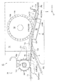
図1は、本実施の形態の部品供給装置の構成を概略的に示している。   FIG. 1 schematically shows the configuration of the component supply device of the present embodiment.

本実施の形態の部品供給装置10は、部品実装装置の移戴ヘッド100のノズル102に対して部品を供給するように構成されている。具体的には、部品供給装置10は、図2に示すキャリアテープ200をその長手方向(テープ送り方向A)に部品供給位置Q1に向かって送り、その部品供給位置Q1でキャリアテープ200に収容された部品を移戴ヘッド100のノズル102に供給するように構成されている。   The component supply device 10 of the present embodiment is configured to supply a component to the nozzle 102 of the transfer head 100 of the component mounting device. Specifically, component feeding apparatus 10 feeds carrier tape 200 shown in FIG. 2 in the longitudinal direction (tape feeding direction A) toward component feeding position Q1, and is accommodated in carrier tape 200 at component feeding position Q1. The components are configured to be supplied to the nozzle 102 of the transfer head 100.

なお、本実施の形態においては、詳細は後述するが、部品供給位置Q1に向かって送られるキャリアテープ200が移動する複数のテープ経路が存在する。複数のテープ経路それぞれにおけるキャリアテープ200の「テープ送り方向A」は、部品実装装置の移載ヘッド100のノズル102に対して部品を供給する位置である部品供給位置Q1に向かってキャリアテープ200が送られるテープ送り方向を意味する。   In the present embodiment, although the details will be described later, there are a plurality of tape paths in which the carrier tape 200 moved toward the component supply position Q1 moves. The “tape feeding direction A” of the carrier tape 200 in each of the plurality of tape paths is a position where the carrier tape 200 is directed to the component supply position Q1 which is a position for supplying a component to the nozzle 102 of the transfer head 100 of the component mounting apparatus. Indicates the tape feed direction to be sent.

図2は、キャリアテープ200の前端側部分(テープ送り方向Aへのテープの移動時において前側になる端側部分(前端210))を示している。なお、図2に示す直交座標系u−v−wにおいて、u軸方向はテープ幅方向に対応し、v軸方向はテープ長手方向に対応し、w軸方向はテープ厚み方向に対応している。   FIG. 2 shows the front end portion of the carrier tape 200 (the end portion (front end 210) which is the front side when the tape moves in the tape feeding direction A). In the orthogonal coordinate system u-v-w shown in FIG. 2, the u-axis direction corresponds to the tape width direction, the v-axis direction corresponds to the tape longitudinal direction, and the w-axis direction corresponds to the tape thickness direction. .

図2に示すように、キャリアテープ200は、部品実装装置の移戴ヘッド100のノズル102に供給される部品を収容する複数の部品収容部202がテープ長手方向(v軸方向)に並んで形成された主面204aを備えるベーステープ204と、部品を収容した状態の部品収容部202を覆うようにベーステープ204の主面204aに貼り付けられたトップテープ206とを有する。また、キャリアテープ200は、そのベーステープ204にテープ長手方向に並んで形成され、テープ厚み方向(w軸方向)に貫通する複数の送り孔208を有する。   As shown in FIG. 2, in the carrier tape 200, a plurality of component accommodating portions 202 for accommodating components to be supplied to the nozzles 102 of the transfer head 100 of the component mounting apparatus are formed side by side in the tape longitudinal direction (v axis direction) And a top tape 206 attached to the main surface 204a of the base tape 204 so as to cover the component storage portion 202 in a state in which components are stored. The carrier tape 200 is formed on the base tape 204 side by side in the longitudinal direction of the tape, and has a plurality of feed holes 208 penetrating in the thickness direction of the tape (w-axis direction).

図2に示すように、トップテープ206は、送り孔208が形成された部分を除くベーステープ204の主面204aの部分に貼り付けられている。   As shown in FIG. 2, the top tape 206 is attached to a portion of the main surface 204 a of the base tape 204 except for the portion where the feed holes 208 are formed.

図1に戻り、部品供給装置10は、本体部12と、本体部12内に形成された主テープ経路P0と、主テープ経路P0に沿ってキャリアテープ200をテープ長手方向のテープ送り方向Aに送るためのテープ送り機構としての複数のスプロケット14〜18と、ベーステープ204からトップテープ206を剥離するためのトップテープ剥離部20とを有する。   Returning to FIG. 1, the component supply device 10 includes the main body portion 12, the main tape path P0 formed in the main body portion 12, and the carrier tape 200 in the tape feeding direction A along the main tape path P0. It has a plurality of sprockets 14 to 18 as a tape feeding mechanism for feeding, and a top tape peeling portion 20 for peeling the top tape 206 from the base tape 204.

部品供給装置10の本体部12の主テープ経路P0の始端側(テープ送り方向Aの上流側の端側)には、キャリアテープ200を本体部12内に投入するためのテープ投入口12aが設けられている。なお、キャリアテープ200は、トップテープ206が貼り付けられた側であるベーステープ204の主面204aを上方に向けた状態でテープ長手方向(テープ送り方向A)にテープ投入口12aに投入される。   A tape insertion port 12a for inserting the carrier tape 200 into the main body 12 is provided on the start end side (the upstream end side of the tape feeding direction A) of the main tape path P0 of the main body 12 of the component supply device 10. It is done. The carrier tape 200 is inserted into the tape slot 12a in the tape longitudinal direction (tape feed direction A) with the main surface 204a of the base tape 204 on the side to which the top tape 206 is attached facing upward. .

また、トップテープ剥離部20によってトップテープ206を剥離されたベーステープ204における部品収容部202内の部品を部品実装装置の移戴ヘッド100のノズル102が上方から吸着できるように、主テープ経路P0の上方に配置された部品取り出し口12bを部品供給装置10は備える。すなわち、部品取り出し口12bが、移戴ヘッド100のノズル102が部品を吸着する位置である部品供給位置Q1に設けられている。   In addition, the main tape path P0 is provided so that the nozzle 102 of the transfer head 100 of the component mounting apparatus can adsorb a component in the component storage unit 202 of the base tape 204 from which the top tape 206 has been peeled off by the top tape peeling unit 20. The component supply device 10 is provided with a component outlet 12b disposed above. That is, the component outlet 12b is provided at the component supply position Q1 at which the nozzle 102 of the transfer head 100 sucks a component.

複数のスプロケット14〜18は、主テープ経路P0に沿ってキャリアテープ200をテープ長手方向であるテープ送り方向Aに送るために、主テープ経路P0に設けられている。複数のスプロケット14〜18は、その歯14a〜18aがキャリアテープ200の送り孔208に係合した状態で回転することにより、キャリアテープ200を主テープ経路P0に沿ってテープ送り方向Aに、部品取り出し口12b(部品供給位置Q1)に向かって送る。   A plurality of sprockets 14-18 are provided in the main tape path P0 to feed the carrier tape 200 in the tape feed direction A, which is the longitudinal direction of the tape, along the main tape path P0. The plurality of sprockets 14 to 18 are rotated in a state in which the teeth 14a to 18a are engaged with the feed holes 208 of the carrier tape 200, whereby the carrier tape 200 is moved in the tape feed direction A along the main tape path P0. It sends toward the extraction port 12b (component supply position Q1).

部品供給装置10のトップテープ剥離部20は、トップテープ206を剥離するためのブレード状部材であって、部品供給位置Q1で移載ヘッド100のノズル102が部品を吸着できるように、部品供給位置Q1に対してテープ送り方向Aの上流側のトップテープ剥離位置Q2でベーステープ204からトップテープ206を順次、剥離する。   The top tape peeling section 20 of the component feeding device 10 is a blade-like member for peeling the top tape 206, and the component feeding position is such that the nozzle 102 of the transfer head 100 can adsorb components at the component feeding position Q1. The top tape 206 is sequentially peeled off from the base tape 204 at the top tape peeling position Q2 on the upstream side in the tape feeding direction A with respect to Q1.

具体的には、トップテープ剥離部20は、トップテープ剥離位置Q2に配置された刃先20aを備える。トップテープ剥離部20の刃先20aは、スプロケット16によって主テープ経路P0に沿ってテープ送り方向Aに送られているキャリアテープ200のテープ送り方向Aの前端210側から、ベーステープ204とトップテープ206との間に進入する。トップテープ剥離部20の刃先20aがベーステープ204とトップテープ206との間に進入した状態で、キャリアテープ200がテープ送り方向Aに送られることにより、トップテープ206がベーステープ204から連続的に剥離される。それにより、部品収容部202に収容されている部品が外部に露出する。その結果、部品実装装置の移載ヘッド100のノズル102が、トップテープ剥離位置Q2に対してテープ送り方向Aの下流側に位置する部品供給位置Q1で、外部に露出した部品を部品取り出し口12bを介して取り出すことができる。   Specifically, the top tape peeling section 20 includes a cutting edge 20a disposed at the top tape peeling position Q2. The cutting edge 20a of the top tape peeling section 20 is the base tape 204 and the top tape 206 from the front end 210 side of the tape feeding direction A of the carrier tape 200 being fed along the main tape path P0 by the sprocket 16 in the tape feeding direction A. Enter between. With the cutting edge 20a of the top tape peeling section 20 entering between the base tape 204 and the top tape 206, the carrier tape 200 is fed in the tape feeding direction A, whereby the top tape 206 is continuously fed from the base tape 204. It is exfoliated. As a result, the components stored in the component storage unit 202 are exposed to the outside. As a result, components exposed to the outside at the component supply position Q1 at which the nozzle 102 of the transfer head 100 of the component mounting apparatus is located downstream of the top tape peeling position Q2 in the tape feeding direction A Can be taken out.

なお、トップテープ206は、部品収容部202に収容されている部品が外部に露出するように、そのテープ幅方向全体がベーステープ204から剥離されてもよいし、または、テープ幅方向の一部がベーステープ204から部分的に剥離されてもよい。剥離に代わって、トップテープ206は、切断されて開封されてもよい。すなわち、部品収容部202内から部品を移載ヘッド100のノズル102が取り出すことができるように、部品が収容されている部品収容部202上からトップテープ204を取り除くことができればよい。   In the top tape 206, the entire tape width direction may be peeled off from the base tape 204 so that the component stored in the component storage unit 202 is exposed to the outside, or a part of the tape width direction May be partially peeled off from the base tape 204. Instead of peeling, the top tape 206 may be cut and opened. That is, the top tape 204 only needs to be removed from above the component storage unit 202 in which the component is stored so that the nozzle 102 of the transfer head 100 can extract the component from the inside of the component storage unit 202.

また、本実施の形態の部品供給装置10は、複数のキャリアテープ200を、順次、部品供給位置Q1に向かってテープ送り方向Aに送るように構成されている。すなわち、部品供給位置Q1で部品を部品実装装置の移載ヘッド100のノズル102に供給している最中の先行のキャリアテープ(先行キャリアテープ)200に続いて、次に部品を供給する予定の後続のキャリアテープ(後続キャリアテープ)200を送るように、部品供給装置10は構成されている。以下、先行のキャリアテープと後続のキャリアテープとを区別して説明する必要がある場合、先行のキャリアテープの符号には「A」を付与し、後続のキャリアテープの符号には「B」を付与する。   In addition, the component supply device 10 of the present embodiment is configured to sequentially feed the plurality of carrier tapes 200 in the tape feeding direction A toward the component supply position Q1. That is, after the preceding carrier tape (preceding carrier tape) 200 in the process of supplying the component to the nozzle 102 of the transfer head 100 of the component mounting apparatus at the component supply position Q1, the component will be supplied next. The component supply device 10 is configured to feed the subsequent carrier tape (following carrier tape) 200. Hereinafter, when it is necessary to distinguish and describe the preceding carrier tape and the following carrier tape, "A" is given to the code of the preceding carrier tape, and "B" is given to the code of the following carrier tape. Do.

図3は、部品供給装置10の部品投入口12a近傍の拡大図である。なお、図3は、部品供給装置10の本体部12にキャリアテープが投入されていない状態を示している。   FIG. 3 is an enlarged view of the vicinity of the component insertion port 12 a of the component supply device 10. FIG. 3 shows a state in which the carrier tape is not inserted into the main body 12 of the component supply device 10.

複数のキャリアテープ200を、順次、部品供給位置Q1に向かってテープ送り方向Aに送るために、本実施の形態の部品供給装置10は、図3に示すように、主テープ経路P0のテープ送り方向Aの上流側端にそれぞれ接続された第1および第2の副テープ経路P1およびP2を有する。   In order to sequentially feed the plurality of carrier tapes 200 in the tape feeding direction A toward the component feeding position Q1, as shown in FIG. 3, the component feeding device 10 of the present embodiment performs tape feeding of the main tape path P0. It has first and second secondary tape paths P1 and P2 connected to the upstream end in the direction A, respectively.

具体的には、主テープ経路P0は、部品供給装置10の本体12のテープ投入口12a側から部品供給位置Q1に向かってテープ送り方向Aに延在する。第1の副テープ経路P1は、図示しないテープリール(キャリアテープの第1の供給リール)からテープ投入口12aにおける主テープ経路P0のテープ送り方向Aの上流側端P0’に向かって延在する。一方、第2の副テープ経路P2は、図示しない別のテープリール(キャリアテープの第2の供給リール)から主テープ経路P1のテープ送り方向Aの上流側端P0’に向かって延在する。すなわち、第1および第2のテープ経路P1、P2は、主テープ経路P0のテープ送り方向Aの上流側端P0’で合流する。   Specifically, the main tape path P0 extends in the tape feeding direction A from the side of the tape input port 12a of the main body 12 of the component supply device 10 toward the component supply position Q1. The first secondary tape path P1 extends from an unshown tape reel (a first supply reel of carrier tape) toward the upstream end P0 'of the main tape path P0 at the tape insertion port 12a in the tape feeding direction A of the main tape path P0. . On the other hand, the second secondary tape path P2 extends from another tape reel (the second supply reel of the carrier tape, not shown) toward the upstream end P0 'of the main tape path P1 in the tape feed direction A. That is, the first and second tape paths P1 and P2 join at the upstream end P0 'of the main tape path P0 in the tape feed direction A.

また、テープ投入口12aの近傍において、第1の副テープ経路P1は、第2の副テープ経路P2の上方に位置する。   Further, in the vicinity of the tape insertion slot 12a, the first secondary tape path P1 is located above the second secondary tape path P2.

本実施の形態の場合、第1の副テープ経路P1は、主テープ経路P0のテープ送り方向Aの上流側端P0’に対して、例えば水平方向(Y軸方向)に接続する。一方、第2の副テープ経路P2は、第1の副テープ経路P1の下方に位置し、主テープ経路P0のテープ送り方向Aの上流側端P0’に対してテープ送り方向Aで、例えば斜め上方向(鉛直方向であるZ軸方向と水平方向であるY軸方向の間の方向)に接続する。すなわち、第1の副テープ経路P1と第2のテープ経路P2は、テープ厚み方向(Z軸方向)の異なる位置にそれぞれ配置されている。   In the case of the present embodiment, the first secondary tape path P1 is connected, for example, in the horizontal direction (Y-axis direction) to the upstream end P0 'of the main tape path P0 in the tape feeding direction A. On the other hand, the second secondary tape path P2 is located below the first secondary tape path P1 and is, for example, oblique in the tape feeding direction A with respect to the upstream end P0 ′ of the main tape path P0 in the tape feeding direction A. It connects in the upper direction (direction between the Z-axis direction which is the vertical direction and the Y-axis direction which is the horizontal direction). That is, the first secondary tape path P1 and the second tape path P2 are disposed at different positions in the tape thickness direction (Z-axis direction).

詳細は後述するが、先行キャリアテープ200Aおよび後続キャリアテープ200Bの両方が部品供給装置10の本体部12に配置されている場合、先行キャリアテープ200Aは第2の副テープ経路P2上に配置され、後続キャリアテープ200Bは第1の副テープ経路P1上に配置される。   Although details will be described later, when both the leading carrier tape 200A and the trailing carrier tape 200B are disposed in the main body 12 of the component supply device 10, the leading carrier tape 200A is disposed on the second secondary tape path P2, The subsequent carrier tape 200B is disposed on the first secondary tape path P1.

図3に示すように、部品供給装置10は、テープ投入口12aのテープ送り方向Aの上流側に、第1の副テープ経路P1上に配置されたキャリアテープ200をテープ送り方向Aに移動可能に保持するテープ保持ユニット30を有する。   As shown in FIG. 3, the component feeding apparatus 10 can move the carrier tape 200 disposed on the first secondary tape path P1 in the tape feeding direction A on the upstream side of the tape feeding direction A of the tape inlet 12 a. The tape holding unit 30 holds the tape.

図4は、図3に示すB−B線断面図であって、具体的には、第1の副テープ経路P1上のキャリアテープ200のテープ長手方向と直交する(テープ送り方向Aに見た)テープ保持ユニット30の断面を示している。図5は、一部の図示が省略されたテープ保持ユニット30の斜視図である。   4 is a cross-sectional view taken along the line B-B shown in FIG. 3. Specifically, it is orthogonal to the tape longitudinal direction of the carrier tape 200 on the first secondary tape path P1 (see in the tape feeding direction A) ) A cross section of the tape holding unit 30 is shown. FIG. 5 is a perspective view of the tape holding unit 30 of which a part is omitted.

テープ保持ユニット30は、第1の副テープ経路P1に沿ってキャリアテープ200が移動するように該キャリアテープ200をガイドする第1および第2のテープガイド部32L、32Rと、第1の副テープ経路P1上にてテープ送り方向Aに移動されるキャリアテープ200を保持するピンローラ34とを有する。   The tape holding unit 30 includes first and second tape guide portions 32L and 32R for guiding the carrier tape 200 so that the carrier tape 200 moves along the first sub tape path P1, and the first sub tape path. And a pin roller 34 for holding the carrier tape 200 moved in the tape feeding direction A on the path P1.

図4および図5に示すように、本実施の形態の場合、第1および第2のテープガイド部32L、32Rは、キャリアテープ200の少なくともテープ厚み方向(Z軸方向)のガイドを行うテープガイドとして機能するガイドブロック36L、36Rと、キャリアテープ200のテープ幅方向(X軸方向)のガイドまたは案内を行うテープガイドとして機能する固定ブラケット38および可動ブラケット40(特許請求の範囲の「ピンローラ支持部」に対応)とによって構成されている。   As shown in FIGS. 4 and 5, in the case of the present embodiment, the first and second tape guides 32L, 32R are tape guides for guiding the carrier tape 200 at least in the tape thickness direction (Z-axis direction). The guide block 36L, 36R functioning as the fixed bracket 38 and the movable bracket 40 functioning as a guide for guiding or guiding the tape width direction (X-axis direction) of the carrier tape 200 in the tape width direction (X axis direction) It corresponds to ") and.

ガイドブロック36L、36Rは、ブロック状の部材であって、図4に示すように、第1の副テープ経路P1上のキャリアテープ200におけるベーステープ204の裏面(主面204aと反対側の面)204b側に配置され、第1の副テープ経路P1上のキャリアテープ200を下方側よりそれぞれガイドする。具体的には、送り孔208側であるキャリアテープ200のテープ幅方向(x軸方向)の一方側がガイドブロック36L上に載置され、一方、送り孔208側に対して反対側であるテープ幅方向の他方側がガイドブロック36R上に載置される。   The guide blocks 36L and 36R are block-like members, and as shown in FIG. 4, the back surface (surface opposite to the main surface 204a) of the base tape 204 in the carrier tape 200 on the first sub tape path P1. The carrier tape 200 is disposed on the side 204 b and guides the carrier tape 200 on the first secondary tape path P 1 from the lower side. Specifically, one side of the tape width direction (x-axis direction) of the carrier tape 200 which is the feed hole 208 side is mounted on the guide block 36 L, while the tape width which is the opposite side to the feed hole 208 side The other side of the direction is placed on the guide block 36R.

また、理由は後述するが、第1および第2のテープガイド部32L、32R(ガイドブロック36L、36R)は、第1の副テープ経路P1上のキャリアテープ200におけるテープ幅方向(x軸方向)に互いに対向した状態で且つ間隔をあけてテープ保持ユニット30に設けられている。   Although the reason will be described later, the first and second tape guides 32L, 32R (guide blocks 36L, 36R) are in the tape width direction (x-axis direction) of the carrier tape 200 on the first sub-tape path P1. The tape holding unit 30 is provided facing each other at an interval.

図3〜図5に示すように、第1のテープガイド部32Lとして機能する固定ブラケット38は、プレート状であって、第1の副テープ経路P1上のキャリアテープ200の送り孔208側を水平方向(Y軸方向)にテープ送り方向Aに延在するように配置され、部品供給装置10の本体部側12に固定されている、固定ブラケット38はまた、第1の副テープ経路P1に配置されたキャリアテープ200におけるテープ幅方向(X軸方向)の送り孔208側の端面(側面)204cに対向する内側面38aを備える。その固定ブラケット38の内側面38aにガイドブロック36Lは取り付けられている。   As shown in FIGS. 3 to 5, the fixing bracket 38 functioning as the first tape guide portion 32L is plate-shaped, and the feed hole 208 side of the carrier tape 200 on the first sub tape path P1 is horizontal. The fixing bracket 38, which is arranged to extend in the tape feeding direction A in the direction (Y-axis direction) and is fixed to the main body side 12 of the component supply device 10, is also arranged in the first secondary tape path P1. The carrier tape 200 has an inner side surface 38a opposite to an end surface (side surface) 204c on the side of the feed hole 208 in the tape width direction (X-axis direction) in the carrier tape 200. The guide block 36L is attached to the inner side surface 38a of the fixing bracket 38.

一方、第2のテープガイド部32Rとして機能する可動ブラケット40は、部品供給装置10の本体部12に対して移動可能に支持されている。具体的には、可動ブラケット40は、図4に示すように、例えば薄板を折り曲げることによって構成され、それにより、キャリアテープ200のテープ幅方向(X軸方向)に対向する2つの側壁部40a、40bと、側壁部40a、40bを連結する天板部40cとを備える。すなわち、天板部40cのテープ幅方向の両端それぞれから下方に向かって側壁部40a、40bが延在している。   On the other hand, the movable bracket 40 functioning as the second tape guide portion 32R is movably supported with respect to the main body portion 12 of the component supply device 10. Specifically, as shown in FIG. 4, the movable bracket 40 is formed, for example, by bending a thin plate, whereby two side wall portions 40a opposed in the tape width direction (X-axis direction) of the carrier tape 200, 40b and a top plate portion 40c connecting the side wall portions 40a and 40b. That is, side walls 40a and 40b extend downward from each end of the top plate 40c in the tape width direction.

可動ブラケット40の側壁部40bは、第1の副テープ経路P1上のキャリアテープ200における送り孔208側とは反対側のテープ幅方向(X軸方向)の端面(側面)204dに対向する内側面40dを備える。その可動ブラケット40の側壁部40bの内側面40dにガイドブロック36Rは取り付けられている。   The side wall portion 40b of the movable bracket 40 is an inner side surface facing the end surface (side surface) 204d in the tape width direction (X-axis direction) opposite to the feed hole 208 side in the carrier tape 200 on the first sub tape path P1. 40 d is provided. The guide block 36R is attached to the inner side surface 40d of the side wall portion 40b of the movable bracket 40.

また、固定ブラケット38の内側面38aおよび可動ブラケット40における側壁部40bの内側面40dは、キャリアテープ200のテープ幅方向位置(X軸方向位置)を位置決めし、第1の副テープ経路Pに沿ってキャリアテープ200が案内されてテープ送り方向Aに移動するようにガイドする。   Further, the inner side surface 38a of the fixed bracket 38 and the inner side surface 40d of the side wall portion 40b of the movable bracket 40 position the tape width direction position (the position in the X axis direction) of the carrier tape 200. The carrier tape 200 is guided to move in the tape feeding direction A.

このような第1および第2のテープガイド部32L、32Rは、テープ幅方向のガイド(固定ブラケット38の内側面38aおよび可動ブラケット40における側壁部40bの内側面40d)とテープ厚さ方向のガイド(ガイドブロック36L、36R)とをすることにより、キャリアテープ200は第1の副テープ経路P1に沿ってテープ送り方向Aに移動することができる。   The first and second tape guides 32L and 32R are guides in the tape width direction (the inner surface 38a of the fixed bracket 38 and the inner surface 40d of the side wall 40b of the movable bracket 40) and the guides in the tape thickness direction. By using (guide blocks 36L, 36R), the carrier tape 200 can be moved in the tape feeding direction A along the first secondary tape path P1.

なお、理由は後述するが、ピンローラ34が設けられる可動ブラケット40は、第1の副テープ経路P1上のキャリアテープ200におけるテープ幅方向(X軸方向)に延在する回転中心線C1を中心として旋回可能に、部品供給装置10の本体部12のテープ投入口12aのテープ送り方向Aの上流側に支持されている。具体的には、図3に示すように、可動ブラケット40は、側壁部40aから延在するアーム部40eを備え、このアーム部40eを介して部品供給装置10の本体部12に旋回可能(第1の副テープ経路P1上のキャリアテープ200に対して上方向に離れる方向に移動可能)に支持されている。   Although the reason will be described later, the movable bracket 40 provided with the pin roller 34 is centered on a rotation center line C1 extending in the tape width direction (X-axis direction) in the carrier tape 200 on the first sub tape path P1. It is supported on the upstream side of the tape feeding direction A of the tape insertion port 12 a of the main body 12 of the component supply device 10 so as to be pivotable. Specifically, as shown in FIG. 3, the movable bracket 40 includes an arm portion 40e extending from the side wall portion 40a, and can be pivoted to the main body portion 12 of the component supply device 10 via the arm portion 40e It is supported so as to be able to move upward in a direction away from the carrier tape 200 on one secondary tape path P1.

図3および図4に示すように、ピンローラ34は、ローラ本体部34aと、ローラ本体部34aの外周部34bに設けられて第1の副テープ経路P1上のキャリアテープ200における送り孔208に係合する複数のピン(歯)34cとを備える。   As shown in FIGS. 3 and 4, the pin roller 34 is provided on the roller body 34a and the outer periphery 34b of the roller body 34a and engaged with the feed hole 208 in the carrier tape 200 on the first sub tape path P1. And a plurality of mating pins (tooth) 34c.

本実施の形態の場合、第1の副テープ経路P1上のキャリアテープ200に対してテープ厚み方向の上方向に相対的に移動可能なピンローラ34のローラ本体部34aは、円筒形状であって、第1の副テープ経路P1上のキャリアテープ200におけるテープ幅方向(X軸方向)に延在する回転中心線C2を中心として回転する。ピンローラ34のローラ本体部34aはまた、第1のテープ経路P1上のキャリアテープ200におけるベーステープ204の主面204aに対向する外周部34bを備える。その外周部34bと第1および第2のテープガイド部32L、32Rのガイドブロック36L、36Rとの間に予めキャリアテープ200が通過可能な間隙lを形成するように、ピンローラ34はテープ保持ユニット30に配置されている。例えば、部品供給装置10に使用される可能性がある特に薄いキャリアテープ(例えば0.25〜0.6mm)が通過可能なテープ厚み方向(Z軸方向)の寸法(例えば、0.15〜0.5mm)を備える間隙が形成される。すなわち、ピンローラ34のローラ本体部34aとガイドブロック36L、36Rとの間の間隙は、薄いキャリアテープ200が容易に通過してテープ詰まりが発生しにくいテープ厚み方向の寸法(少なくとも0.15mm以上の相対的な間隔l)を備える。なお、間隙lは少なくともキャリアテープ200の送り孔208側であるテープ幅方向の一方側のガイドブロック36Lとピンローラ本体部34aとの間に形成されればよく、一方、テープ幅方向の他方側のガイドブロック36Rとピンローラ本体部34aとの間の間隙は、間隙l以上の寸法(例えば、間隙lの寸法+0.5mm)であればよい。   In the case of the present embodiment, the roller main body portion 34a of the pin roller 34, which can move relatively upward in the tape thickness direction with respect to the carrier tape 200 on the first auxiliary tape path P1, has a cylindrical shape, The carrier tape 200 on the first secondary tape path P1 rotates about a rotation center line C2 extending in the tape width direction (X-axis direction). The roller main body portion 34a of the pin roller 34 also includes an outer peripheral portion 34b opposed to the main surface 204a of the base tape 204 in the carrier tape 200 on the first tape path P1. The pin roller 34 is a tape holding unit 30 so as to form a gap l through which the carrier tape 200 can pass in advance between the outer peripheral portion 34b and the guide blocks 36L and 36R of the first and second tape guides 32L and 32R. Is located in For example, dimensions (e.g., 0.15 to 0) in the tape thickness direction (Z-axis direction) through which particularly thin carrier tapes (e.g., 0.25 to 0.6 mm) which may be used for the component feeding device 10 can pass. A gap of .5 mm) is formed. That is, in the gap between the roller body portion 34a of the pin roller 34 and the guide blocks 36L and 36R, the dimension in the tape thickness direction (thin 0.15 mm or more It comprises relative spacing l). The gap l may be formed at least between the guide block 36L on one side in the tape width direction which is the feed hole 208 side of the carrier tape 200 and the pin roller main body 34a, while the other side on the other side in the tape width direction. The gap between the guide block 36R and the pin roller main body 34a may have a size equal to or larger than the gap 1 (for example, the size of the gap l + 0.5 mm).

図4に示すように、ピンローラ34のローラ本体部34aの外周部34bに、第1の副テープ経路P1上のキャリアテープ200の送り孔208と係合する複数のピン(歯)34cが設けられている。複数のピン34cは、図3に示すように、ローラ本体部34aの回転中心線C2に対して放射方向に該ローラ本体部34aから突出している。このピン34cが送り孔208に係合した状態でピンローラ34のローラ本体部34aが回転中心線C2を中心としてキャリアテープ200をテープ送り方向Aへ送るように回転すると、キャリアテープ200が第1の副テープ経路P1に沿って移動する。   As shown in FIG. 4, the outer peripheral portion 34b of the roller main body portion 34a of the pin roller 34 is provided with a plurality of pins (teeth) 34c engaged with the feed holes 208 of the carrier tape 200 on the first sub tape path P1. ing. As shown in FIG. 3, the plurality of pins 34c project from the roller body 34a in the radial direction with respect to the rotation center line C2 of the roller body 34a. When the roller body portion 34a of the pin roller 34 rotates so as to feed the carrier tape 200 in the tape feed direction A centering on the rotation center line C2 with the pin 34c engaged with the feed hole 208, the carrier tape 200 becomes the first. Move along the secondary tape path P1.

なお、テープ投入口12aのテープ送り方向Aの上流側に位置するピンローラ34のピン34cにキャリアテープ200の送り孔208が容易に係合するように、第1および第2のテープガイド部32L、32Rは、第1の副テープ経路P1上のキャリアテープ200の送り孔208に係合されるピンローラ34のピン34に対してテープ送り方向Aの上流側からキャリアテープ200を案内するようにガイドするのが好ましい。   Note that the first and second tape guide portions 32L, 32L, so that the feed hole 208 of the carrier tape 200 easily engages with the pin 34c of the pin roller 34 located on the upstream side of the tape insertion direction 12A. 32R guides the carrier tape 200 from the upstream side in the tape feeding direction A with respect to the pin 34 of the pin roller 34 engaged with the feed hole 208 of the carrier tape 200 on the first secondary tape path P1. Is preferred.

すなわち、好ましくは、第1および第2のテープガイド部32L、32Rにおけるガイドブロック36L、36Rと固定ブラケット38の内側面38aおよび可動ブラケット40における側壁部40bの内側面40dとが、ピンローラ34に対してテープ送り方向Aの上流側からテープ送り方向Aに延在するように構成される。   That is, preferably, the guide blocks 36L, 36R in the first and second tape guides 32L, 32R, the inner surface 38a of the fixed bracket 38 and the inner surface 40d of the side wall 40b in the movable bracket 40 The tape feeding direction A is configured to extend from the upstream side in the tape feeding direction A.

特に、第1および第2のテープガイド部32L、32Rは、テープ幅方向のガイドとして機能する固定ブラケット38の内側面38aおよび可動ブラケット40における側壁部40bの内側面40dを、キャリアテープ200の送り孔208と係合されるピンローラ34のピン34cに対してテープ送り方向Aの上流側に少なくとも備えるのが好ましい。これにより、ピンローラ34のピン34cとキャリアテープ200の送り孔208とのテープ幅方向の位置(X軸方向位置)を合わせた(案内させた)状態で該キャリアテープ200をピンローラ34の下方を通過させることができる。その結果、ピンローラ34のピン34cにキャリアテープ200の送り孔208を容易に係合させることができる。   In particular, the first and second tape guides 32L, 32R feed the carrier tape 200 along the inner surface 38a of the fixed bracket 38 functioning as a guide in the tape width direction and the inner surface 40d of the side wall 40b of the movable bracket 40. It is preferable to have at least the upstream side of the tape feeding direction A with respect to the pin 34 c of the pin roller 34 engaged with the hole 208. As a result, the carrier tape 200 passes under the pin roller 34 in a state in which the position (the position in the X-axis direction) of the pin 34 c of the pin roller 34 and the feed hole 208 of the carrier tape 200 is aligned (guided). It can be done. As a result, the feed hole 208 of the carrier tape 200 can be easily engaged with the pin 34 c of the pin roller 34.

また、ピンローラ34は、送り孔208にピン34cが係合しているキャリアテープ200のテープ送り方向Aに対する逆方向の移動を規制するように構成されている。具体的には、送り孔208にピン34cが係合しているキャリアテープ200のテープ送り方向Aへの移動によって回転するピンローラ34のローラ本体部34aの回転方向(図3において反時計回り方向)に対する逆方向に、ピンローラ34のローラ本体部34は回転不可能に構成されている。   Further, the pin roller 34 is configured to restrict the movement of the carrier tape 200 in which the pin 34 c is engaged with the feed hole 208 in the reverse direction with respect to the tape feeding direction A. Specifically, the rotation direction of the roller main body 34a of the pin roller 34 which rotates by movement of the carrier tape 200 in which the pin 34c is engaged with the feed hole 208 in the tape feeding direction A (counterclockwise direction in FIG. 3) The roller main body 34 of the pin roller 34 is configured to be non-rotatable in the opposite direction to that of FIG.

本実施の形態の場合、ピンローラ34のローラ本体部34aは、その内部に収容されたクラッチ機構(ワンウェイクラッチ)42を介して支持シャフト44に支持されている。支持シャフト44は、第1の副テープ経路P1上のキャリアテープ200におけるテープ幅方向(X軸方向)に延在する。また、シャフト44の両端はそれぞれ、図4に示すように可動ブラケット40の側壁部40a、40bに支持されている。   In the case of the present embodiment, the roller main body portion 34 a of the pin roller 34 is supported by the support shaft 44 via a clutch mechanism (one-way clutch) 42 housed inside. The support shaft 44 extends in the tape width direction (X-axis direction) of the carrier tape 200 on the first secondary tape path P1. Further, as shown in FIG. 4, both ends of the shaft 44 are supported by the side wall portions 40 a and 40 b of the movable bracket 40.

クラッチ機構42は、支持シャフト44に対するピンローラ34のローラ本体部34aの回転方向を一方向に制限するように構成されている。すなわち、送り孔208にピン34cが係合しているキャリアテープ200がテープ送り方向Aに移動することができる方向のローラ本体部34aの回転のみ許容するようにクラッチ機構42は構成されている。   The clutch mechanism 42 is configured to restrict the rotational direction of the roller body 34 a of the pin roller 34 with respect to the support shaft 44 in one direction. That is, the clutch mechanism 42 is configured to allow only the rotation of the roller body 34 a in the direction in which the carrier tape 200 in which the pin 34 c is engaged with the feed hole 208 can move in the tape feeding direction A.

このようなピンローラ34により、第1の副テープ経路P1上のキャリアテープ200は、テープ送り方向Aに対する逆方向への移動が規制される。すなわち、第1の副テープ経路P1上のキャリアテープ200が、テープ送り方向Aに対する逆方向に移動することにより、部品供給装置10の本体部12から意図せず抜けることが抑制される。その結果、キャリアテープ200を第1の副テープ経路P1上に確実に待機させることができる。なお、キャリアテープ200を意図して抜きたい場合、ピンローラ34が設けられている可動ブラケット40をテープ厚み方向に相対的に移動させて、キャリアテープ200の上方へ離間させるように移動させることにより、ピン34cとキャリアテープ200の送り孔208の係合がはずれ、それによりキャリアテープ200を意図して容易に抜くことができる。   The movement of the carrier tape 200 on the first secondary tape path P1 in the reverse direction with respect to the tape feeding direction A is restricted by such a pin roller 34. That is, when the carrier tape 200 on the first secondary tape path P1 moves in the reverse direction with respect to the tape feeding direction A, the unintentional removal from the main body 12 of the component supply device 10 is suppressed. As a result, the carrier tape 200 can be reliably made to stand by on the first secondary tape path P1. When the carrier tape 200 is intended to be pulled out, the movable bracket 40 provided with the pin roller 34 is relatively moved in the tape thickness direction to move the carrier tape 200 away from the upper side, The pin 34c and the feed hole 208 of the carrier tape 200 are disengaged so that the carrier tape 200 can be intentionally pulled out easily.

また、図4に示すように、ピンローラ34のローラ本体部34は、第1の副テープ経路上のキャリアテープ200の概ねテープ幅方向(X軸方向)全体にわたってそのベーステープ204の主面204aと対向する外周部34bを備えるが、本発明の実施の形態はこれに限らない。例えば、ローラ本体部34の外周部34bは、第1の副テープ経路P1上のキャリアテープ200における送り孔208のみに対向するように構成してもよい。例えばスプロケットのように、ローラ本体部34aは、複数のピン34cを形成することが可能な最小限のテープ幅方向(X軸方向)の大きさを備えてもよい。   Further, as shown in FIG. 4, the roller main body portion 34 of the pin roller 34 and the main surface 204 a of the base tape 204 substantially over the entire tape width direction (X-axis direction) of the carrier tape 200 on the first secondary tape path. Although the opposing outer peripheral part 34b is provided, embodiment of this invention is not restricted to this. For example, the outer circumferential portion 34b of the roller main body portion 34 may be configured to face only the feed holes 208 in the carrier tape 200 on the first secondary tape path P1. For example, like a sprocket, the roller body 34a may have a minimum size in the tape width direction (X-axis direction) in which a plurality of pins 34c can be formed.

上述したような第1および第2の副テープ経路P1およびP2を用いて、複数のキャリアテープ200を、順次、部品供給位置Q1に向かってテープ送り方向Aに送る方法について説明する。   A method of sequentially feeding a plurality of carrier tapes 200 in the tape feeding direction A toward the component supply position Q1 using the first and second secondary tape paths P1 and P2 as described above will be described.

前提として、本実施の形態の部品供給装置10は、部品供給装置10の本体部12にキャリアテープ200を投入するとき、第1の副テープ経路P1を使用するように構成されている。例えば、図3に示すように、キャリアテープ200が投入されていない状態の部品供給装置10の本体部12に対してキャリアテープ200(すなわち先行キャリアテープ200A)を投入するときに、第1の副テープ経路P1が使用される。また例えば、部品供給装置10の本体部12に既に投入されているキャリアテープ200(先行キャリアテープ200A)に続くキャリアテープ200(後続キャリアテープ200B)を部品供給装置10の本体部12に投入するときに、第1の副テープ経路P1が使用される。   As a premise, the component supply device 10 of the present embodiment is configured to use the first secondary tape path P1 when the carrier tape 200 is inserted into the main body 12 of the component supply device 10. For example, as shown in FIG. 3, when the carrier tape 200 (i.e., the preceding carrier tape 200A) is inserted into the main body 12 of the component supply device 10 in a state in which the carrier tape 200 is not inserted, the first sub The tape path P1 is used. Also, for example, when the carrier tape 200 (following carrier tape 200B) following the carrier tape 200 (preceding carrier tape 200A) already loaded into the main body 12 of the component feeding apparatus 10 is loaded into the main body 12 of the component feeding apparatus 10. , The first secondary tape path P1 is used.

図3に示すように、例えば作業者の手作業により、キャリアテープ200(先行キャリアテープ200A)が第1の副テープ経路P1上に配置される。具体的には、まず、キャリアテープ200(先行キャリアテープ200A)のテープ送り方向Aの前端部が、テープ保持ユニット30の第1および第2のテープガイド部32L、32Rのガイドブロック36L、36R上に配置される。   As shown in FIG. 3, the carrier tape 200 (preceding carrier tape 200A) is disposed on the first secondary tape path P1 by, for example, a manual operation of an operator. Specifically, first, the front end portion of the carrier tape 200 (preceding carrier tape 200A) in the tape feeding direction A is on the guide blocks 36L and 36R of the first and second tape guides 32L and 32R of the tape holding unit 30. Will be placed.

テープ保持ユニット30の第1および第2のテープガイド部32L、32Rのガイドブロック36L、36R上に配置されたキャリアテープ200(先行キャリアテープ200A)が、作業者の手作業によってテープ送り方向Aに送られる。作業者によってテープ送り方向Aに送られたキャリアテープ200(先行キャリアテープ200A)は、テープガイド36L、36Rとピンローラ34との間(間隙l)に進入し、その送り孔208がピンローラ34のピン34cに係合する。送り孔208がピンローラ34のピン34cに係合すると、キャリアテープ200(先行キャリアテープ200A)は、部品供給装置10から意図せず抜けることがなくなる。   The carrier tape 200 (preceding carrier tape 200A) disposed on the guide blocks 36L and 36R of the first and second tape guides 32L and 32R of the tape holding unit 30 is manually moved by the operator in the tape feeding direction A. Sent. The carrier tape 200 (preceding carrier tape 200A) fed in the tape feeding direction A by the operator enters between the tape guides 36L, 36R and the pin roller 34 (gap l), and the feed hole 208 thereof is a pin of the pin roller 34. Engage 34c. When the feed hole 208 engages with the pin 34 c of the pin roller 34, the carrier tape 200 (preceding carrier tape 200 A) will not come off the parts supply device 10 unintentionally.

送り孔208にピン34cが係合した状態のピンローラ34を作業者がキャリアテープ200をテープ送り方向Aに送るように回転させると、キャリアテープ200(先行キャリアテープ200A)が第1の副テープ経路P1に沿ってテープ送り方向Aに部品供給装置10の本体部12の投入口12a内に向かって送られる。   When the worker rotates the pin roller 34 with the pin 34c engaged with the feed hole 208 so as to feed the carrier tape 200 in the tape feeding direction A, the carrier tape 200 (preceding carrier tape 200A) is the first secondary tape path. The sheet P is fed in the tape feeding direction A toward the inside of the insertion port 12 a of the main body 12 of the component feeding device 10.

投入口12aを通過したキャリアテープ200(先行キャリアテープ200A)は、作業者の手作業によるピンローラ34の回転により、薄いキャリアテープであっても、テープ送り方向Aに向かって確実に送られ、主テープ経路P0に沿ってテープ送り方向Aの最も上流側に位置するスプロケット14に向かう。   The carrier tape 200 (preceding carrier tape 200A) that has passed through the inlet 12a is reliably fed in the tape feeding direction A, even if it is a thin carrier tape, by the rotation of the pin roller 34 manually by the operator. Toward the most upstream sprocket 14 in the tape feed direction A along the tape path P0.

図6に示すように、スプロケット14の歯14aにキャリアテープ200(先行キャリアテープ200A)の送り孔208が係合すると、ピンローラ34によるテープ送りが完了する。例えば作業者が「テープセット完了ボタン」等のボタンを押すことにより、また例えば送り孔208がスプロケット14の歯14aに係合する主テープ経路P0上の位置にキャリアテープ200が到達したことをセンサ(図示せず)が検出することにより、さらに例えば、ピンローラ34の回転によって移動中のキャリアテープ200によるスプロケット14の回転の開始を検出することにより、歯14aにキャリアテープ200(先行キャリアテープ200A)の送り孔208に係合した状態のスプロケット14が回転し始める。   As shown in FIG. 6, when the feed holes 208 of the carrier tape 200 (preceding carrier tape 200A) are engaged with the teeth 14a of the sprocket 14, the tape feeding by the pin roller 34 is completed. For example, when the operator presses a button such as "tape set complete button", for example, it is detected that the carrier tape 200 has reached a position on the main tape path P0 where the feed hole 208 engages with the teeth 14a of the sprocket 14. (Not shown) detects the start of the rotation of the sprocket 14 by the carrier tape 200 being moved by, for example, the rotation of the pin roller 34, the carrier tape 200 (preceding carrier tape 200A) on the teeth 14a. The sprocket 14 in the state engaged with the feed hole 208 of is started to rotate.

スプロケット14の回転により、図6に示すように、キャリアテープ200(先行キャリアテープ200A)は主テープ経路P0に沿ってテープ送り方向Aにさらに下流側に位置するスプロケット16に向かって送られる。スプロケット16の歯16aにキャリアテープ200(先行キャリアテープ200A)の送り孔208が係合すると、スプロケット14は回転を停止し、自由に回転可能な自由回転状態(スプロケット14を駆動するモータ(図示せず)の励磁が解除された状態)に移行する。   By the rotation of the sprocket 14, as shown in FIG. 6, the carrier tape 200 (preceding carrier tape 200A) is fed toward the sprocket 16 located further downstream in the tape feed direction A along the main tape path P0. When the feed hole 208 of the carrier tape 200 (preceding carrier tape 200A) engages with the teeth 16a of the sprocket 16, the sprocket 14 stops rotating and a freely rotatable state (a motor for driving the sprocket 14 (shown in FIG. Shift to the state where the excitation is released.

スプロケット16によってテープ送り方向Aに送られるキャリアテープ200(先行キャリアテープ200A)は、図1に示すように、トップテープ剥離位置Q1でトップテープ剥離部20の刃先20aによってそのトップテープ206が剥離され、続いてトップテープ剥離部20と部品供給位置Q1との間に位置するスプロケット18の歯18aにその送り孔208が係合する。そして、2つのスプロケット16、18によってキャリアテープ200(先行キャリアテープ200A)はテープ送り方向Aに部品供給位置Q1に向かって送られる。   The top tape 206 of the carrier tape 200 (preceding carrier tape 200A) fed in the tape feed direction A by the sprocket 16 is peeled off by the cutting edge 20a of the top tape peeling portion 20 at the top tape peeling position Q1 as shown in FIG. Subsequently, the feed hole 208 engages with the teeth 18a of the sprocket 18 located between the top tape peeling portion 20 and the parts supply position Q1. Then, the carrier tape 200 (preceding carrier tape 200A) is fed toward the component supply position Q1 in the tape feeding direction A by the two sprockets 16 and 18.

2つのスプロケット16、18によってテープ送り方向Aに送られるキャリアテープ200(先行キャリアテープ200A)は、図1に示すように、部品供給位置Q1で部品実装装置の移載ヘッド100のノズル102に対してトップテープ206の剥離によって外部に露出した部品を供給する。   The carrier tape 200 (preceding carrier tape 200A) fed in the tape feed direction A by the two sprockets 16, 18 is, as shown in FIG. 1, the nozzle 102 of the transfer head 100 of the component mounting apparatus at the component supply position Q1. Supply parts exposed to the outside by peeling off the top tape 206.

先行キャリアテープ200が部品実装装置の移載ヘッド100のノズル102に対して部品を供給している最中の任意のタイミングに、先行キャリアテープ200Aに続いて次に部品を供給する予定の後続キャリアテープ200Bが本体部12に配置される。具体的には、図6に示すように第1の副テープ経路P1上を移動する先行キャリアテープ200Aが第2の副テープ経路P2に移動され、それにより空いた第1の副テープ経路P1に後続キャリアテープ200Bが配置される。このことについて説明する。   The subsequent carrier tape 200 is to be supplied with a component following the preceding carrier tape 200A at any timing during supply of a component to the nozzle 102 of the transfer head 100 of the component mounting apparatus. The tape 200 B is disposed on the main body 12. Specifically, as shown in FIG. 6, the leading carrier tape 200A moving on the first secondary tape path P1 is moved to the second secondary tape path P2, and as a result, the first secondary tape path P1 is released. The subsequent carrier tape 200B is placed. This will be described.

先行キャリアテープ200Aの第1の副テープ経路P1から第2の副テープ経路P2への移動は、テープ保持ユニット30の可動ブラケット40を回転中心線C1を中心として旋回させることによって実行される。   The movement of the leading carrier tape 200A from the first secondary tape path P1 to the second secondary tape path P2 is performed by pivoting the movable bracket 40 of the tape holding unit 30 around the rotation center line C1.

図6に示すように先行キャリアテープ200Aが第1の副テープ経路P1上をテープ送り方向Aに移動している状態から、作業者がテープ保持ユニット30の可動ブラケット40を回転中心線C1を中心として旋回させる。   As shown in FIG. 6, the operator moves the movable bracket 40 of the tape holding unit 30 around the rotation center line C1 from the state where the preceding carrier tape 200A is moved in the tape feeding direction A on the first sub tape path P1. Rotate as.

先行キャリアテープ200Aの主面204a側に配置されたテープ保持ユニット30の可動ブラケット40の旋回により、図7に示すように、可動ブラケット40に支持されているピンローラ34および第2のテープガイド部32Rが上昇する、すなわち第1の副テープ経路P1上の先行キャリアテープ200Aの主面204a側から離間する方向に移動する。   As shown in FIG. 7, the pin roller 34 and the second tape guide portion 32R supported by the movable bracket 40 by the pivoting of the movable bracket 40 of the tape holding unit 30 disposed on the main surface 204a side of the leading carrier tape 200A. Is raised, that is, moved in a direction away from the main surface 204a side of the preceding carrier tape 200A on the first secondary tape path P1.

テープ保持ユニット30の可動ブラケット40の旋回によってピンローラ34が上昇すると、固定ブラケット38の第1のテープガイド部32L(ガイドブロック36L)がピンローラ34に対して相対的にテープ厚み方向(Z軸方向)に離間する方向に移動する。それにより、先行キャリアテープ200Aの送り孔208に係合しているピンローラ34のピン34cが(図4参照)、図7に示すように第1の副テープ経路P1上の先行キャリアテープ200Aの送り孔208内から相対的に退避する。その結果、先行キャリテープ200Aは、送り孔208側の第1のテープガイド部32L(ガイドブロック36L)とピンローラ34のローラ本体部34aとの間からテープ幅方向(X軸方向)に移動可能な状態にされる。   When the pin roller 34 ascends due to the turning of the movable bracket 40 of the tape holding unit 30, the first tape guide portion 32L (guide block 36L) of the fixed bracket 38 relative to the pin roller 34 in the tape thickness direction (Z-axis direction) Move in the direction away from. Thereby, the pin 34c of the pin roller 34 engaged with the feed hole 208 of the leading carrier tape 200A (see FIG. 4) feeds the leading carrier tape 200A on the first secondary tape path P1 as shown in FIG. Relatively retract from the hole 208. As a result, the leading carry tape 200A can be moved in the tape width direction (X-axis direction) from between the first tape guide portion 32L (guide block 36L) on the feed hole 208 side and the roller main portion 34a of the pin roller 34. Be put into a state.

また、テープ保持ユニット30の可動ブラケット40の旋回によって第2のテープガイド部32R(ガイドブロック36R)が先行キャリアテープ200Aの主面204a側から離間する方向に上昇すると、ガイドブロック36R上に載置されている先行キャリアテープ200Aのテープ幅方向の他方側(送り孔208側の反対側)が持ち上げられる。これにより、先行キャリアテープ200Aは部分的にねじれる(図7において、点線はねじれる前の先行キャリアテープ200Aを示す)。具体的には、先行キャリアテープ200Aは、第2のテープガイド部32R近傍を中心として旋回し、第2のテープガイド部32R(ガイドブロック36R)近傍の部分が他の部分に比べてねじれる。   In addition, when the second tape guide portion 32R (guide block 36R) ascends in the direction of separating from the main surface 204a side of the leading carrier tape 200A by the pivoting of the movable bracket 40 of the tape holding unit 30, it is placed on the guide block 36R. The other side (the opposite side to the feed hole 208 side) of the preceding carrier tape 200A in the tape width direction is lifted. Thereby, the leading carrier tape 200A is partially twisted (in FIG. 7, the dotted line indicates the leading carrier tape 200A before being twisted). Specifically, the leading carrier tape 200A pivots around the vicinity of the second tape guide portion 32R, and the portion in the vicinity of the second tape guide portion 32R (guide block 36R) is twisted as compared with the other portions.

図7に示すように送り孔208側とは反対側であるテープ幅方向の他方側が持ち上がるように先行キャリアテープ200Aがねじれた状態からさらに可動ブラケット40の第2のテープガイド部32R(ガイドブロック36R)が上昇すると、図8に示すように、先行キャリアテープ200Aのテープ幅方向の他方側が、ガイドブロック36R上からすべり落ち、ねじれを解消しつつガイドブロック36Rの下方に移動する。   As shown in FIG. 7, the second tape guide portion 32R of the movable bracket 40 is further moved from the state where the leading carrier tape 200A is twisted so that the other side in the tape width direction opposite to the feed hole 208 side is lifted. 8), the other side of the leading carrier tape 200A in the tape width direction slips off from the top of the guide block 36R, and moves downward of the guide block 36R while eliminating the twist.

図8に示すように、第2のテープガイド部32Rが先行キャリアテープ200Aより上に相対的に上昇し、送り孔208側とは反対側である先行キャリアテープ200Aのテープ幅方向の他方側が第2のテープガイド部32R(ガイドブロック36R)の支持を失うと、先行キャリアテープ200Aは下方に落下する。すなわち、第1の副テープ経路P1上の先行キャリアテープ200Aは、第1および第2のテープガイド部32L、32Rの間を通過し、第1の副テープ経路P1の下方に存在する第2の副テープ経路P2に向かって移動する。これにより、図9および図10に示すように、先行キャリアテープ200Aは、第1の副テープ経路P1から第2の副テープ経路P2に移動される。   As shown in FIG. 8, the second tape guide portion 32R is relatively lifted above the preceding carrier tape 200A, and the other side of the preceding carrier tape 200A in the tape width direction opposite to the feed hole 208 side is the first one. When the support of the second tape guide portion 32R (guide block 36R) is lost, the preceding carrier tape 200A falls downward. That is, the preceding carrier tape 200A on the first secondary tape path P1 passes between the first and second tape guides 32L and 32R, and is located below the first secondary tape path P1. Move toward the secondary tape path P2. As a result, as shown in FIGS. 9 and 10, the preceding carrier tape 200A is moved from the first secondary tape path P1 to the second secondary tape path P2.

ここで、第1の副テープ経路P1上のキャリアテープ200を下方側よりガイド(支持)するためのガイド部材が、テープ保持ユニット30の第1および第2のテープガイド部32L、32R(ガイドブロック36L、36R)とに分かれている理由について説明する。   Here, the guide members for guiding (supporting) the carrier tape 200 on the first secondary tape path P1 from the lower side are the first and second tape guide portions 32L, 32R of the tape holding unit 30 (guide blocks The reason for the division into 36L and 36R) will be described.

例えば、第1の副テープ経路P1上のキャリアテープ200を下方側より1つのガイド部材がガイド(支持)する場合を考える。この場合、第1の副テープ経路P1上からその下方に位置する第2の副テープ経路P2上にキャリアテープ200を移動させるとき、第1および第2の副テープ経路P1、P2の間に位置する1つのガイド部材を迂回するようにキャリアテープ200を移動させる必要がある。すなわち、キャリアテープ200のテープ幅方向位置(X軸方向位置)を大きく変える必要がある。そのために、1つのガイド部材をキャリアテープ200が迂回するためのスペースを確保する必要がある。   For example, consider a case where one guide member guides (supports) the carrier tape 200 on the first secondary tape path P1 from the lower side. In this case, when the carrier tape 200 is moved from the top of the first secondary tape path P1 to the second secondary tape path P2 located below the first secondary tape path P1, the position is between the first and second secondary tape paths P1 and P2. It is necessary to move the carrier tape 200 so as to bypass one of the guide members. That is, it is necessary to largely change the tape width direction position (X axis direction position) of the carrier tape 200. Therefore, it is necessary to secure a space for the carrier tape 200 to bypass one guide member.

このような1つのガイド部材をキャリアテープ200が迂回するためのスペースを設けると、部品供給装置10のテープ幅方向(X軸方向)のサイズを必然的に大きくする必要がある。その結果、1台の部品実装装置に対してテープ幅方向(X軸方向)に密に並べた状態で搭載される部品供給装置10の搭載数は減少する。   If a space is provided for the carrier tape 200 to bypass such one guide member, the size of the component supply device 10 in the tape width direction (X-axis direction) must be necessarily increased. As a result, the number of mounted component supply devices 10 mounted in a state of being closely arranged in the tape width direction (X-axis direction) with respect to one component mounting device decreases.

一方、図4に示すように、第1の副テープ経路P1上のキャリアテープ200をテープ幅方向(X軸方向)に分かれた第1および第2のテープガイド部32L、32R(ガイドブロック36L、36R)がテープ幅方向の両端側の下方からガイド(支持)する場合、第1の副テープ経路P1上からその下方に位置する第2の副テープ経路P2上にキャリアテープ200を移動させるとき、そのキャリアテープ200は、第1および第2のテープガイド部32L、32Rの間を通るように容易に通過することができる。すなわち、キャリアテープ200は、テープ幅方向位置(X軸方向位置)を大きく変えることなく、第1の副テープ経路P1上からその下方の第2の副テープ経路P2上に移動することができる。したがって、部品供給装置10のテープ幅方向(X軸方向)のサイズを小さくすることができる。   On the other hand, as shown in FIG. 4, the first and second tape guide portions 32L and 32R (the guide blocks 36L, When the carrier tape 200 is moved from above the first secondary tape path P1 onto the second secondary tape path P2 located below from above the first secondary tape path P1 when the 36R) guides (supports) from below the tape width direction both ends, The carrier tape 200 can easily pass between the first and second tape guides 32L, 32R. That is, the carrier tape 200 can be moved from the top of the first secondary tape path P1 to the top of the second secondary tape path P2 below the first secondary tape path P1 without largely changing the tape width direction position (the position in the X-axis direction). Therefore, the size in the tape width direction (X-axis direction) of the component supply device 10 can be reduced.

なお、テープ保持ユニット30の可動ブラケット40の旋回によってピンローラ34が上昇するときに、そのピン34cが第1の副テープ経路P1上のキャリアテープ200(先行キャリアテープ200A)の送り孔208内からテープ厚み方向(Z軸方向)に確実に退避できる(係合が解除される)ようにするのが好ましい。   When the pin roller 34 ascends due to the turning of the movable bracket 40 of the tape holding unit 30, the pin 34c is inserted into the feed hole 208 of the carrier tape 200 (preceding carrier tape 200A) on the first sub tape path P1. It is preferable to be able to reliably retract (disengage the engagement) in the thickness direction (Z-axis direction).

本実施の形態の場合、図7に示すように、第1の副テープ経路P1上のキャリアテープ200(先行キャリアテープ200A)の送り孔208内からテープ厚み方向(Z軸方向)にピンローラ34のピン34cが上昇して退避するときに、ピン34cの退避方向(すなわちテープ厚み方向)側のキャリアテープ200Aの主面204a側で、送り孔208側であるキャリテープのテープ幅方向(X軸方向)の一方側を押さえるテープ押さえ部46を有する。   In the case of this embodiment, as shown in FIG. 7, the pin roller 34 is provided in the tape thickness direction (Z-axis direction) from the inside of the feed hole 208 of the carrier tape 200 (preceding carrier tape 200A) on the first secondary tape path P1. When the pin 34c moves up and retracts, the tape width direction (X-axis direction) of the carry tape on the feed hole 208 side on the main surface 204a side of the carrier tape 200A on the retraction direction (that is, tape thickness direction) side of the pin 34c. Tape holding portion 46 for holding one side of

テープ押さえ部46は、図4に示すように、テープ保持ユニット30の固定ブラケット38の内側面38aから、第1の副テープ経路P1上のキャリアテープ200の送り孔208の上方に向かって延在する部材(または固定ブラケット38の部分)である。テープ押さえ部46はまた、本実施の形態の場合、図3に示すように、第1のテープ押さえ部32Lに対してテープ送り方向Aの下流側に位置する。   The tape holding portion 46 extends from the inner side surface 38a of the fixing bracket 38 of the tape holding unit 30 to the upper side of the feed hole 208 of the carrier tape 200 on the first secondary tape path P1, as shown in FIG. (Or part of the fixing bracket 38). Further, in the case of the present embodiment, as shown in FIG. 3, the tape pressing portion 46 is located downstream of the first tape pressing portion 32L in the tape feeding direction A.

テープ保持ユニット30の可動ブラケット40の旋回によってピンローラ34および第2のテープガイド部32Rが上昇するときに、テープ押さえ部46がキャリアテープ200(先行キャリアテープ200A)をその上方から押さえることにより、ピンローラ34のピン34cがキャリアテープ200(先行キャリアテープ200A)の送り孔208から確実に退避することができる。すなわち、ピンローラ34および第2のテープガイド部32Rとともに、キャリアテープ200(先行キャリアテープ200A)が第1の副テープ経路P1から上方に移動することが抑制される。   When the pin roller 34 and the second tape guide portion 32R are raised by the pivoting of the movable bracket 40 of the tape holding unit 30, the tape holding portion 46 holds the carrier tape 200 (preceding carrier tape 200A) from above, thereby the pin roller The pins 34c of 34 can be reliably retracted from the feed holes 208 of the carrier tape 200 (preceding carrier tape 200A). That is, movement of the carrier tape 200 (preceding carrier tape 200A) upward from the first secondary tape path P1 is suppressed together with the pin roller 34 and the second tape guide portion 32R.

また、図8に示すようにテープ保持ユニット30の可動ブラケット40の旋回によって第2のテープガイド部32Rがキャリアテープ200(先行キャリアテープ200A)の下方側から上方側に移動した後、可動ブラケット40を逆方向に旋回させることにより、第2のテープガイド部32Rによってキャリアテープ200(先行キャリアテープ200A)を下方の第2の副テープ経路P2に向かって押し下げてもよい。これは、例えば、第2のテープガイド部32Rがキャリアテープ200(先行キャリアテープ200A)の下方側から上方側に移動した後に、そのキャリアテープ200(先行キャリアテープ200A)が自然落下しにくい場合に(例えば大きいテープ厚さを備えるキャリアテープの場合に)有効である。   Further, as shown in FIG. 8, the second tape guide portion 32R is moved upward from the lower side of the carrier tape 200 (preceding carrier tape 200A) by the pivoting of the movable bracket 40 of the tape holding unit 30, and then the movable bracket 40 is moved. The second tape guide portion 32R may push the carrier tape 200 (preceding carrier tape 200A) downward toward the second sub-tape path P2 below by pivoting in the opposite direction. This is because, for example, after the second tape guide portion 32R moves from the lower side to the upper side of the carrier tape 200 (preceding carrier tape 200A), the carrier tape 200 (preceding carrier tape 200A) does not easily fall by itself. It is advantageous (e.g. in the case of carrier tapes with large tape thickness).

図9および図10に示すように、先行キャリアテープ200Aが第1の副テープ経路P1から第2の副テープ経路P2上に移動すると、空いた第1の副テープ経路P1に後続キャリアテープ200Bを配置することが可能になる。   As shown in FIGS. 9 and 10, when the preceding carrier tape 200A moves from the first secondary tape path P1 to the second secondary tape path P2, the succeeding carrier tape 200B is moved to the free first secondary tape path P1. It becomes possible to arrange.

後続キャリアテープ200Bは、先行キャリアテープ200Aと同様に、作業者の手作業により、そのテープ送り方向前端部が、テープ保持ユニット30の第1および第2のテープガイド部32L、32Rのガイドブロック36L、36R上に載置される。ガイドブロック36L、36Rに載置された後続キャリアテープ200Bは、作業者の手作業によるテープ送り方向Aへのテープ送りにより、ピンローラ34の下方を通過し、その送り孔208にピンローラ34のピン34cが係合する。これにより、後続キャリアテープ200Bは、意図せず抜けることなく第1の副テープ経路P1上で確実に待機可能である。   The trailing carrier tape 200B, like the leading carrier tape 200A, has its front end portion in the tape feed direction by the manual operation of the operator, and the guide block 36L of the first and second tape guide portions 32L, 32R of the tape holding unit 30. , 36R. The subsequent carrier tape 200B placed on the guide blocks 36L and 36R passes below the pin roller 34 by tape feeding in the tape feeding direction A manually by the operator, and passes through the feed hole 208 to the pin 34c of the pin roller 34. Is engaged. As a result, the subsequent carrier tape 200B can reliably stand by on the first secondary tape path P1 without being unintentionally pulled out.

なお、本実施の形態の部品供給装置10は、第2の副テープ経路P2および主テープ経路P0に沿ってテープ送り方向Aに送られている先行キャリアテープ200Aに続いて、第1の副テープ経路P1上で待機する後続キャリアテープ200Bを自動的に送り始める自動テープ送り機構50を有する。   In the component feeding apparatus 10 of the present embodiment, the first secondary tape is continued following the preceding carrier tape 200A being fed in the tape feeding direction A along the second secondary tape path P2 and the main tape path P0. It has an automatic tape feeding mechanism 50 that automatically starts feeding the following carrier tape 200B waiting on the path P1.

まず、後続キャリアテープ200Bの送りを自動テープ送り機構50によって自動的に開始するために、図11に示すように、後続キャリアテープ200Bのテープ送り方向Aの前端210Bが第1の副テープ経路P1から主テープ経路P0に入った状態で、後続キャリアテープ200Bは待機する。具体的には、作業者がピンローラ34を回転させることにより、後続キャリアテープ200Bのテープ送り方向Aの前端210Bが第1の副テープ経路P1から主テープ経路P0に入れられる。   First, as shown in FIG. 11, in order to automatically start the feeding of the following carrier tape 200B by the automatic tape feeding mechanism 50, the front end 210B of the following carrier tape 200B in the tape feeding direction A is the first secondary tape path P1. The subsequent carrier tape 200B stands by in the state where the main tape path P0 is entered from the above. Specifically, when the worker rotates the pin roller 34, the front end 210B of the subsequent carrier tape 200B in the tape feeding direction A is inserted from the first secondary tape path P1 into the main tape path P0.

また、主テープ経路P0に入った後続キャリアテープ200Bのテープ送り方向Aの前端210Bが第2の副テープ経路P2および第1の副テープ経路P1に沿ってテープ送り方向Aに送られている先行キャリアテープ200Aに重なった状態で、後続キャリアテープ200Bは待機する。   Also, the leading end 210B in the tape feed direction A of the following carrier tape 200B that has entered the main tape path P0 is sent in the tape feed direction A along the second sub tape path P2 and the first sub tape path P1. The subsequent carrier tape 200B stands by in a state of overlapping with the carrier tape 200A.

そのために、主テープ経路P0上のキャリアテープ200に対して上方に配置されて対向する本体部12の上側ガイド面12cおよび該キャリアテープ200に対して下方に配置されて対向する下側ガイド面12dは、テープ投入口12aの近傍において、テープ厚み方向に重なり合う二本のキャリアテープ200が通過可能な間隙をあけている。   For that purpose, the upper guide surface 12c of the main body 12 disposed above and opposed to the carrier tape 200 on the main tape path P0 and the lower guide surface 12d disposed below and opposed to the carrier tape 200 In the vicinity of the tape inlet 12a, there is a gap through which two carrier tapes 200 overlapping in the tape thickness direction can pass.

図11に示すように、自動テープ送り機構50は、テープ送り方向Aの最も上流側に配置されたスプロケット14と、主テープ経路P0上のキャリアテープ200をスプロケット14に向かって付勢する付勢ブロック52と、後続キャリアテープ200Bを待機させるストッパー54とを有する。   As shown in FIG. 11, the automatic tape feeding mechanism 50 urges the sprocket 14 disposed on the most upstream side in the tape feeding direction A and the carrier tape 200 on the main tape path P0 toward the sprocket 14. It has a block 52 and a stopper 54 for holding the following carrier tape 200B on standby.

自動テープ送り機構50の付勢ブロック52は、主テープ経路P0を挟んでスプロケット14に対向するように配置され、主テープ経路P0上(すなわち本体部12の上側ガイド面12cと下側ガイド面12dとの間に配置された)キャリアテープ200をスプロケット14に向かって付勢するように構成されている。具体的には、図3に示すように、付勢ブロック52は、下側ガイド面12dからスプロケット14に向かって進退可能であって、図示しない付勢部材(例えばバネ)によってスプロケット14に向かって付勢されている。図3の二点鎖線は、下側ガイド面12dから後退した状態の付勢ブロック52を示している。   The biasing block 52 of the automatic tape feeding mechanism 50 is disposed to face the sprocket 14 with the main tape path P0 interposed therebetween, and on the main tape path P0 (that is, the upper guide surface 12c and the lower guide surface 12d of the main body 12). And the carrier tape 200 is arranged to be biased toward the sprocket 14). Specifically, as shown in FIG. 3, the biasing block 52 is movable toward and away from the lower guide surface 12d toward the sprocket 14, and is biased toward the sprocket 14 by a biasing member (for example, a spring) not shown. It is energized. The dashed-two dotted line of FIG. 3 has shown the urging | biasing block 52 of the state retracted | saved from the lower side guide surface 12d.

一方、付勢ブロック52に対向するスプロケット14の歯14aは、図3に示すように、上側ガイド面12cから付勢ブロック52に向かって突出している。   On the other hand, as shown in FIG. 3, the teeth 14 a of the sprocket 14 facing the biasing block 52 protrude from the upper guide surface 12 c toward the biasing block 52.

上側ガイド面12cと下側ガイド面12dとの間に配置されたキャリアテープ200は、付勢ブロック52に付勢されて上側ガイド面12cに当接し、その送り孔208がスプロケット14の歯14aに係合する。   The carrier tape 200 disposed between the upper guide surface 12c and the lower guide surface 12d is biased by the biasing block 52 and abuts on the upper guide surface 12c, and the feed hole 208 thereof is in contact with the teeth 14a of the sprocket 14. Engage.

なお、付勢ブロック52とスプロケット14との間に、先行キャリアテープ200Aと後続キャリアテープ200Bとが重なり合う状態で存在する場合、上側の後続キャリアテープ200Bの送り孔208にスプロケット14の歯14aが係合する。   When the leading carrier tape 200A and the trailing carrier tape 200B overlap with each other between the biasing block 52 and the sprocket 14, the teeth 14a of the sprocket 14 are engaged with the feed holes 208 of the upper trailing carrier tape 200B. Match.

自動テープ送り機構50のストッパー54は、本体部12の上側ガイド面12cから下側ガイド面12dに向かって進退可能なテープ係止部54aを備える。   The stopper 54 of the automatic tape feeding mechanism 50 includes a tape engaging portion 54 a which can be advanced and retracted from the upper guide surface 12 c of the main body 12 to the lower guide surface 12 d.

図11に示すように、第2の副テープ経路P2および主テープ経路P0に沿ってスプロケット16(またはスプロケット16、18)(図1参照)によってテープ送り方向Aに送られている先行キャリアテープ200A上に重なる後続キャリアテープ200Bのテープ送り方向Aの前端210Bに、ストッパー54のテープ係止部54aが接触する。その結果、先行キャリアテープ200Aのテープ送り方向Aへの移動とともに、後続キャリアテープ200Bが部品供給位置Q1に向かって移動することが抑制される。   As shown in FIG. 11, the preceding carrier tape 200A being fed in the tape feed direction A by the sprocket 16 (or sprockets 16, 18) (see FIG. 1) along the second secondary tape path P2 and the main tape path P0. The tape engaging portion 54a of the stopper 54 is in contact with the front end 210B in the tape feed direction A of the succeeding carrier tape 200B overlapping the upper portion. As a result, with the movement of the leading carrier tape 200A in the tape feeding direction A, the movement of the following carrier tape 200B toward the component supply position Q1 is suppressed.

付勢ブロック52とスプロケット14との間にキャリアテープ200が存在しない場合または一本のキャリアテープ200のみ存在する場合、ストッパー54のテープ係止部54aは、図3および図6に示すように、上側ガイド面12cから後退している。   When the carrier tape 200 is not present between the biasing block 52 and the sprocket 14 or when only one carrier tape 200 is present, the tape locking portion 54a of the stopper 54 is, as shown in FIGS. 3 and 6, It is retracted from the upper guide surface 12c.

なお、例えば、ストッパー54のテープ係止部54aの進退は、付勢ブロック52の進退に連動して実行される。例えば、付勢ブロック54とスプロケット14との間に二本のキャリアテープ200が存在するときの位置に付勢ブロック52が下がり、それによりストッパー54のテープ係止部54aは上側ガイド面12cから下方に突出する。   Note that, for example, the advancing and retreating of the tape locking portion 54 a of the stopper 54 is executed in conjunction with the advancing and retreating of the biasing block 52. For example, the biasing block 52 is lowered to a position where two carrier tapes 200 are present between the biasing block 54 and the sprocket 14, whereby the tape locking portion 54a of the stopper 54 is downwardly from the upper guide surface 12c. Project to

このような自動テープ送り機構50を部品供給装置10が有することにより、第1の副テープ経路P1上で待機している後続キャリアテープ200Bを、第2の副テープ経路P2および主テープ経路P0に沿ってテープ送り方向Aに送られている先行キャリアテープ200Aに続いて自動的に送ることができる。   The component feeding device 10 having such an automatic tape feeding mechanism 50 allows the subsequent carrier tape 200B waiting on the first secondary tape path P1 to be placed on the second secondary tape path P2 and the main tape path P0. It can be automatically sent following the leading carrier tape 200A being sent along the tape feeding direction A.

以上、本実施の形態によれば、部品実装装置の移載ヘッド100のノズル102に対して先行して部品を供給している先行のキャリアテープ200Aに続いて、次に部品を供給する予定の後続のキャリアテープ200Bを部品供給位置にQ1に向かって送ることができるように、キャリアテープ200が薄い場合であっても、部品供給位置Q1に向かう第1の副テープ経路P1上に後続のキャリアテープ200Bを確実に待機させることができる。   As described above, according to the present embodiment, the component is scheduled to be supplied next to the preceding carrier tape 200A, which supplies the component to the nozzle 102 of the transfer head 100 of the component mounting apparatus. Even if the carrier tape 200 is thin, the subsequent carrier tape 200 on the first secondary tape path P1 toward the component supply position Q1 can be sent to the component supply position Q toward the component supply position 200. The tape 200B can be reliably held on standby.

上述の実施の形態を挙げて本発明を説明したが、本発明は上述の実施の形態に限定されない。   Although the present invention has been described with the above embodiment, the present invention is not limited to the above embodiment.

例えば、上述の実施の形態の部品供給装置10の場合、図5に示すように、テープ保持ユニット30の第1および第2のテープガイド部32L、32Rは、テープ幅方向(X軸方向)に対向するが、本発明の実施の形態はこれに限らない。   For example, in the case of the component feeding apparatus 10 according to the above-described embodiment, as shown in FIG. 5, the first and second tape guides 32L and 32R of the tape holding unit 30 extend in the tape width direction Although it opposes, embodiment of this invention is not restricted to this.

例えば別の実施の形態に係る部品供給装置のテープ保持部130の場合、図12に示すように、第2のテープガイド部132R(それに支持されたガイドブロック36R)のテープ送り方向Aの上流側端が、第1のテープガイド部132L(それに支持されたガイドブロック36L)のテープ送り方向Aの上流側端に比べてテープ送り方向Aの下流側にずれて配置される。これにより、第1の副テープ経路P1上のキャリアテープ200は、第1および第2のテープガイド部132L、132Rの間をテープ厚み方向(上下方向)に通過しやすくなり、第1の副テープ経路P1の下方に位置する第2の副テープ経路P2に落ちやすく(移動しやすく)なる(第1および第2のテープガイド部がテープ幅方向に対向する場合に比べて)。   For example, in the case of the tape holding unit 130 of the component supply device according to another embodiment, as shown in FIG. 12, the upstream side of the tape feeding direction A of the second tape guide unit 132R (guide block 36R supported thereon). The end is disposed on the downstream side in the tape feeding direction A relative to the upstream end of the tape feeding direction A of the first tape guide portion 132L (the guide block 36L supported thereto). As a result, the carrier tape 200 on the first secondary tape path P1 can easily pass between the first and second tape guide portions 132L and 132R in the tape thickness direction (vertical direction), and the first secondary tape can be obtained. It easily falls (is easy to move) to the second secondary tape path P2 located below the path P1 (compared to the case where the first and second tape guide portions face in the tape width direction).

また、テープ保持ユニット30の第1および第2のテープガイド部32L、32Rの間を、第1の副テープ経路P1上のキャリアテープ200が第2の副テープ経路P2に向かって容易に通過できるように、第1および第2のテープガイド部32L、32Rの少なくとも一方を、テープ幅方向(X軸方向)に弾性変形可能な材料を用いて作製してもよい。例えば、上述の実施の形態の場合、テープ保持ユニット30の固定ブラケット38および可動ブラケット40の少なくとも一方が、樹脂材料から作製されてもよい。   Also, the carrier tape 200 on the first secondary tape path P1 can easily pass toward the second secondary tape path P2 between the first and second tape guides 32L and 32R of the tape holding unit 30. Thus, at least one of the first and second tape guides 32L and 32R may be manufactured using a material that can be elastically deformed in the tape width direction (X-axis direction). For example, in the case of the above-described embodiment, at least one of the fixed bracket 38 and the movable bracket 40 of the tape holding unit 30 may be made of a resin material.

さらに、第1の副テープ経路P1上に待機する後続キャリアテープ200Bを、第2の副テープ経路P2および主テープ経路P0に沿ってテープ送り方向Aに送られている先行キャリアテープ200Aに続いて自動的に送る自動テープ送り機構は、上述の実施の形態の自動テープ送り機構に限らない。   Furthermore, the subsequent carrier tape 200B waiting on the first secondary tape path P1 is continued to the leading carrier tape 200A being sent in the tape feed direction A along the second secondary tape path P2 and the main tape path P0. The automatic tape feeding mechanism for automatic feeding is not limited to the automatic tape feeding mechanism of the above-described embodiment.

例えば、別の形態の自動テープ送り機構は、第2の副テープ経路P2および主テープ経路P0に沿ってテープ送り方向に送られている先行キャリアテープ200Aのテープ送り方向Aの後端を検出し、部品供給装置10の本体部12のテープ投入口12aに設けられたセンサ(図示せず)と、テープ保持ユニット30のピンローラ34を回転させるためのモータ(図示せず)とを有する。   For example, another form of automatic tape feeding mechanism detects the trailing end of the tape feeding direction A of the leading carrier tape 200A being fed in the tape feeding direction along the second secondary tape path P2 and the main tape path P0. A sensor (not shown) provided at the tape inlet 12a of the main body 12 of the component supply device 10 and a motor (not shown) for rotating the pin roller 34 of the tape holding unit 30 are provided.

テープ投入口12aに設けられたセンサが先行キャリアテープ200Aの後端を検出すると、モータがピンローラ34を回転させる。これにより、第1の副テープ経路P1上に待機する後続キャリアテープ200Bが、先行キャリアテープ200Aに続いて部品供給位置Q1に向かって送られる。   When the sensor provided at the tape insertion slot 12a detects the rear end of the leading carrier tape 200A, the motor rotates the pin roller 34. As a result, the subsequent carrier tape 200B waiting on the first secondary tape path P1 is sent to the component supply position Q1 following the previous carrier tape 200A.

さらに上述の実施の形態の部品供給装置10の場合、第1の副テープ経路P1上からその下方の第2の副テープ経路P2上への先行キャリアテープ200Aの移動は、テープ保持ユニット30の可動ブラケット40を手作業で旋回させることによって実行される。これに代わって、モータなどの駆動源が可動ブラケット40を旋回させてもよい。   Furthermore, in the case of the component feeding device 10 of the above-described embodiment, the movement of the leading carrier tape 200A from the top of the first secondary tape path P1 to the top of the second secondary tape path P2 below it is the movement of the tape holding unit 30. It is implemented by pivoting the bracket 40 manually. Alternatively, a drive source such as a motor may pivot the movable bracket 40.

加えて、上述の実施の形態の場合、テープ保持ユニット30の可動ブラケット40の旋回により、図7に示すように、第1の副テープ経路P1上の先行キャリアテープ200Aの送り孔208にピン34cが係合しているピンローラ34とともに、送り孔208とは反対側の先行キャリアテープ200Aのテープ幅方向(X軸方向)の他方側を下方からガイドする第2のテープガイド部32R(ガイドブロック36R)が上昇する。しかし、本発明の実施の形態は、これに限らない。   In addition, in the case of the above-described embodiment, the pivot 34 of the movable bracket 40 of the tape holding unit 30 causes the pin 34c in the feed hole 208 of the leading carrier tape 200A on the first secondary tape path P1 as shown in FIG. The second tape guide portion 32R that guides the other side of the tape width direction (X-axis direction) of the preceding carrier tape 200A opposite to the feed hole 208 with the pin roller 34 engaged with the second from the lower side (guide block 36R ) Will rise. However, the embodiment of the present invention is not limited to this.

別の実施の形態の部品供給装置は、ピンローラ34のみが第1の副テープ経路P1上の先行キャリアテープ200Aから上方向に離間するように構成されている。例えば、作業者は、ピンローラ34を移動させることにより、ピンローラ34のピン34cを先行キャリアテープ200Aの送り孔208内から退避させる。次に、作業者は、先行キャリアテープ200Aをつかみ、つかんだ先行キャリアテープ200Aを第1および第2のテープガイド部32L、32Rの間を通過させ、第2の副テープ経路P2上に配置する。これにより、第1の副テープ経路P1からその下方に位置する第2の副テープ経路P2への先行キャリアテープ200Aの移動が完了する。   The component feeding device of another embodiment is configured such that only the pin roller 34 is spaced upward from the leading carrier tape 200A on the first secondary tape path P1. For example, the worker moves the pin roller 34 to retract the pin 34c of the pin roller 34 from the inside of the feed hole 208 of the preceding carrier tape 200A. Next, the operator grasps the leading carrier tape 200A, passes the grasped leading carrier tape 200A between the first and second tape guide portions 32L and 32R, and places it on the second secondary tape path P2. . This completes the movement of the preceding carrier tape 200A from the first secondary tape path P1 to the second secondary tape path P2 located below it.

すなわち、本発明は、広義には、複数の送り孔がテープ長手方向に並んでそれぞれ形成されているキャリアテープを、キャリアテープに収納された部品を部品実装装置の移載ヘッドに対して供給する部品供給位置へ送る部品供給装置において、本体部と、前記本体部に形成され、キャリアテープを前記部品供給位置へ案内するテープ経路と、前記テープ経路のテープ投入口に投入された先行のキャリアテープとこの先行のキャリアテープに続いて次に部品を供給する予定の後続のキャリアテープを、順次、前記部品供給位置へ送るキャリアテープ送り機構と、前記先行のキャリアテープの上に先端部が重なった状態で前記テープ投入口に投入された前記後続のキャリアテープを、前記先行のキャリアテープから上方に離れた位置で保持するテープ保持ユニットとを備えた、部品供給装置である。 That is, according to the present invention, in a broad sense, the carrier tape in which a plurality of feed holes are respectively formed in the longitudinal direction of the tape is supplied to the transfer head of the component mounting apparatus. In a component feeding apparatus for feeding to a component feeding position , a main body, a tape path formed on the main body and guiding a carrier tape to the component feeding position, and a preceding carrier tape inserted into a tape insertion port of the tape path And a carrier tape feeding mechanism for sequentially feeding a subsequent carrier tape which is to supply parts next to the preceding carrier tape to the part supply position, and a tip portion is superimposed on the preceding carrier tape And hold the subsequent carrier tape inserted into the tape insertion port in a state where the subsequent carrier tape is separated from the preceding carrier tape at an upper position. And a flop holding unit, a component supply device.

本発明は、キャリアテープをテープ経路に沿って送りつつ、テープ経路上に配置されたトップテープ剥離部の刃先がキャリアテープのテープ送り方向の前端側からベーステープとトップテープとの間に進入することによってベーステープからトップテープを少なくとも部分的に剥離する部品供給装置であれば適用可能である。   In the present invention, while the carrier tape is fed along the tape path, the cutting edge of the top tape peeling section disposed on the tape path enters between the base tape and the top tape from the front end side of the carrier tape in the tape feeding direction. It is applicable if it is the components supply apparatus which peels a top tape at least partially from a base tape by this.

10 部品供給装置
32L 第1のテープガイド部
32R 第2のテープガイド部
34 ピンローラ
34a ローラ本体部
34b 外周部
34c ピン
38a テープ幅方向ガイド部(固定ブラケットの内側面)
40 ピンローラ支持部(可動ブラケット)
40a テープ幅方向ガイド部(可動ブラケットの内側面)
200 キャリアテープ
208 送り孔
A テープ送り方向
P0 主テープ経路
P1 副テープ経路
P2 副テープ経路
DESCRIPTION OF SYMBOLS 10 Parts supply apparatus 32L 1st tape guide part 32R 2nd tape guide part 34 Pin roller 34a Roller main body part 34b Outer peripheral part 34c Pin 38a Tape width direction guide part (inner side of fixed bracket)
40 pin roller support (movable bracket)
40a Tape width direction guide (inner side of movable bracket)
200 Carrier Tape 208 Feed Hole A Tape Feed Direction P0 Main Tape Path P1 Secondary Tape Path P2 Secondary Tape Path

Claims (5)

複数の送り孔がテープ長手方向に並んでそれぞれ形成されているキャリアテープを、キャリアテープに収納された部品を部品実装装置の移載ヘッドに対して供給する部品供給位置へ送る部品供給装置において、
本体部と、
前記本体部に形成され、キャリアテープを前記部品供給位置へ案内するテープ経路と、
前記テープ経路のテープ投入口に投入された先行のキャリアテープとこの先行のキャリアテープに続いて次に部品を供給する予定の後続のキャリアテープを、順次、前記部品供給位置へ送るキャリアテープ送り機構と、
前記先行のキャリアテープの上に先端部が重なった状態で前記テープ投入口に投入された前記後続のキャリアテープを、前記先行のキャリアテープから上方に離れた位置で保持するテープ保持ユニットとを備え
前記テープ保持ユニットは、前記後続のキャリアテープの複数の送り孔に対して一方側の下面の部分を支持するとともに前記一方側の側面をガイドする第1のテープガイド部と、前記送り孔に対して他方側の下面の部分を支持するとともに前記他方側の側面をガイドする第2のテープガイド部とを有し、
前記第1のテープガイド部と前記第2のテープガイド部は、前記後続のキャリアテープの幅方向に互いに対向した状態で且つ間隔をあけて設けられた、部品供給装置。
A component feeding device for feeding a carrier tape, in which a plurality of feed holes are respectively formed in a row in the longitudinal direction of the tape, to a component feeding position where components housed in the carrier tape are fed to a transfer head of a component mounting device.
Body part,
A tape path formed in the main body and guiding a carrier tape to the component supply position;
A carrier tape feeding mechanism for sequentially feeding the preceding carrier tape inserted into the tape insertion port of the tape path and the following carrier tape scheduled to supply parts following the preceding carrier tape to the part supply position. When,
And a tape holding unit for holding the subsequent carrier tape inserted into the tape insertion port in a state in which the leading end is overlapped on the preceding carrier tape at a position separated upward from the preceding carrier tape. ,
The tape holding unit supports a portion of the lower surface on one side with respect to a plurality of feed holes of the subsequent carrier tape, and a first tape guide portion that guides the side surface on the one side; A second tape guide portion for supporting the lower surface portion on the other side and guiding the side surface on the other side;
The component supply device , wherein the first tape guide portion and the second tape guide portion are provided facing each other in the width direction of the subsequent carrier tape and spaced apart from each other .
前記第2のテープガイド部は、前記第1のテープガイド部に対して相対的にテープ厚み方向へ移動可能である、請求項に記載の部品供給装置。
The component supply device according to claim 1 , wherein the second tape guide portion is movable in the tape thickness direction relatively to the first tape guide portion.
前記第2のテープガイド部は、キャリアテープの幅方向に延在する回転中心線を中心に旋回可能である、請求項に記載の部品供給装置。
The parts feeding device according to claim 2 , wherein the second tape guide portion is pivotable about a rotation center line extending in the width direction of the carrier tape.
前記第2のテープガイド部のテープ送り方向の上流側の端が、前記第1のテープガイド部のテープ送り方向の上流側端に比べてテープ送り方向の下流側にずれて配置されている、請求項1〜3のいずれか一項に記載の部品供給装置。
The upstream end of the second tape guide portion in the tape feeding direction is offset to the downstream side in the tape feeding direction as compared with the upstream end of the first tape guide portion in the tape feeding direction. The components supply apparatus as described in any one of Claims 1-3 .
前記第1のテープガイド部および前記第2のテープガイド部の少なくとも一方が、テープ幅方向に弾性変形可能な材料から作製されている、請求項に記載の部品供給装置。 The component supply device according to claim 1 , wherein at least one of the first tape guide portion and the second tape guide portion is made of a material that can be elastically deformed in the tape width direction.
JP2017225927A 2017-11-24 2017-11-24 Parts supply device Active JP6534049B2 (en)

Priority Applications (1)

Application Number Priority Date Filing Date Title
JP2017225927A JP6534049B2 (en) 2017-11-24 2017-11-24 Parts supply device

Applications Claiming Priority (1)

Application Number Priority Date Filing Date Title
JP2017225927A JP6534049B2 (en) 2017-11-24 2017-11-24 Parts supply device

Related Parent Applications (1)

Application Number Title Priority Date Filing Date
JP2013255365A Division JP6331122B2 (en) 2013-12-10 2013-12-10 Component supply apparatus and component supply method

Related Child Applications (1)

Application Number Title Priority Date Filing Date
JP2019092144A Division JP6782468B2 (en) 2019-05-15 2019-05-15 Parts supply device

Publications (2)

Publication Number Publication Date
JP2018050071A JP2018050071A (en) 2018-03-29
JP6534049B2 true JP6534049B2 (en) 2019-06-26

Family

ID=61766590

Family Applications (1)

Application Number Title Priority Date Filing Date
JP2017225927A Active JP6534049B2 (en) 2017-11-24 2017-11-24 Parts supply device

Country Status (1)

Country Link
JP (1) JP6534049B2 (en)

Families Citing this family (1)

* Cited by examiner, † Cited by third party
Publication number Priority date Publication date Assignee Title
JP6782468B2 (en) * 2019-05-15 2020-11-11 パナソニックIpマネジメント株式会社 Parts supply device

Family Cites Families (5)

* Cited by examiner, † Cited by third party
Publication number Priority date Publication date Assignee Title
US7850040B2 (en) * 2006-10-23 2010-12-14 Hover-Davis, Inc. Component tape feeder
JP5302846B2 (en) * 2009-10-19 2013-10-02 株式会社日立ハイテクインスツルメンツ Component supply device and electronic component mounting device
US8678065B2 (en) * 2010-03-30 2014-03-25 Sts Co., Ltd. Carrier tape feeder
JP5891354B2 (en) * 2012-01-19 2016-03-23 パナソニックIpマネジメント株式会社 Tape feeder and component mounting apparatus
CN104322159B (en) * 2012-03-23 2018-05-29 雅马哈发动机株式会社 Assembly supply device and apparatus for mounting component

Also Published As

Publication number Publication date
JP2018050071A (en) 2018-03-29

Similar Documents

Publication Publication Date Title
JP6331122B2 (en) Component supply apparatus and component supply method
US8353424B2 (en) Component feeder
WO2011077880A1 (en) Electronic circuit component supplying apparatus
US9743570B2 (en) Component supplying apparatus and component supplying method
JP6334689B2 (en) feeder
WO2015029125A1 (en) Feeder
JP6431048B2 (en) feeder
JP7158176B2 (en) Automatic tape loading device
KR20150015547A (en) Method for mounting electronic component and device for mounting electronic component
JPWO2016143040A1 (en) feeder
WO2016203627A1 (en) Feeder
JP6534049B2 (en) Parts supply device
JP5624657B2 (en) Tape feeder
JP6782468B2 (en) Parts supply device
JP5535380B2 (en) Tape feeder
US11856704B2 (en) Tape auto-loading device and tape linking method therefor
JP2018041892A (en) feeder
JP2016092060A (en) Component supply device, surface mounting machine, and supply method for component
JP7398756B2 (en) parts supply device
JP2022028935A (en) feeder
JP2003051696A (en) Method for changing reel in tape feeder and the tape feeder
JP6678416B2 (en) feeder
JP2015015443A (en) Component supply device and component supply method
JP5913508B2 (en) Tape feeder
US11974402B2 (en) Component supply device

Legal Events

Date Code Title Description
A977 Report on retrieval

Free format text: JAPANESE INTERMEDIATE CODE: A971007

Effective date: 20180718

A131 Notification of reasons for refusal

Free format text: JAPANESE INTERMEDIATE CODE: A131

Effective date: 20180731

A601 Written request for extension of time

Free format text: JAPANESE INTERMEDIATE CODE: A601

Effective date: 20180927

A521 Written amendment

Free format text: JAPANESE INTERMEDIATE CODE: A523

Effective date: 20181126

TRDD Decision of grant or rejection written
A01 Written decision to grant a patent or to grant a registration (utility model)

Free format text: JAPANESE INTERMEDIATE CODE: A01

Effective date: 20190416

A61 First payment of annual fees (during grant procedure)

Free format text: JAPANESE INTERMEDIATE CODE: A61

Effective date: 20190515

R150 Certificate of patent or registration of utility model

Ref document number: 6534049

Country of ref document: JP

Free format text: JAPANESE INTERMEDIATE CODE: R150