JP6876270B2 - Rear body structure of the vehicle - Google Patents
Rear body structure of the vehicle Download PDFInfo
- Publication number
- JP6876270B2 JP6876270B2 JP2017073793A JP2017073793A JP6876270B2 JP 6876270 B2 JP6876270 B2 JP 6876270B2 JP 2017073793 A JP2017073793 A JP 2017073793A JP 2017073793 A JP2017073793 A JP 2017073793A JP 6876270 B2 JP6876270 B2 JP 6876270B2
- Authority
- JP
- Japan
- Prior art keywords
- vehicle
- partition
- wall portion
- closed cross
- side wall
- Prior art date
- Legal status (The legal status is an assumption and is not a legal conclusion. Google has not performed a legal analysis and makes no representation as to the accuracy of the status listed.)
- Active
Links
Images


Description
本発明は、車体後部にトランクルームを持つノッチバックタイプの車両であって、車室内とトランクルームとを仕切るパーティション部の左右両端部が車室内側壁部に接続固定されている車両の後部車体構造に関する。 The present invention relates to a notchback type vehicle having a trunk room at the rear of the vehicle body, and relates to a rear body structure of the vehicle in which both left and right ends of a partition portion separating the vehicle interior and the trunk room are connected and fixed to the side wall of the vehicle interior.
従来、車体後部にトランクルームを持つ、いわゆるノッチバックタイプの車両においては、車室内とトランクルームとを仕切るパーティション部が設けられている。
この種の車両としては従来、例えば特許文献1に示された車体構造の車両が知られている。
この特許文献1の車両では、車体後部の左右の側壁の略中間高さ部間には、リヤシートの後方において、スピーカ等が取り付けられるリヤパッケージトレイが設けられている。このリヤパッケージトレイには、剛性の向上のため、前縁部に沿って車幅方向に延びるクロスメンバが設けられている。これらリヤパッケージトレイとクロスメンバの両側部には、車体側壁を構成するサイドパネルとの間を結合する結合メンバが設けられている。
Conventionally, in a so-called notchback type vehicle having a trunk room at the rear of the vehicle body, a partition portion for partitioning the vehicle interior and the trunk room is provided.
As a vehicle of this type, for example, a vehicle having a vehicle body structure shown in
In the vehicle of
上記の特許文献1に記載された技術では、リヤパッケージトレイとクロスメンバの両側部を結合する結合メンバには、車体前後方向に沿った閉じ断面が設けられていないため、車体の捩じれに対する剛性を確保することができなかった。
In the technique described in
本発明は、トランクヒンジ取付部の剛性を向上させ、トランクリッド開閉時の品質を向上させるとともに、捩じれに対する車体剛性を向上させることができる車両の後部車体構造を提供することを目的とする。 An object of the present invention is to provide a rear vehicle body structure of a vehicle capable of improving the rigidity of the trunk hinge mounting portion, improving the quality when opening and closing the trunk lid, and improving the vehicle body rigidity against twisting.
本発明は、上記課題を解決するため、車体後部にトランクルームを有する車両であって、車室内とトランクルームとを仕切るパーティション部と、前記パーティション部の端部が接続固定される車室内側壁部と、を備え、前記端部に、車両の前後方向に沿って閉じ断面構造が形成される車両の後部車体構造において、前記車室内側壁部は、ホイールハウスのショックアブソーバ取付部から上方向に延びるリヤピラーインナリンフォースを有し、前記リヤピラーインナリンフォースが前記閉じ断面構造の一部を構成することにある。 In order to solve the above problems, the present invention comprises a vehicle having a trunk room at the rear of the vehicle body, a partition portion for partitioning the vehicle interior and the trunk room, a vehicle interior side wall portion to which the end portion of the partition portion is connected and fixed, and a vehicle interior side wall portion. In the rear body structure of the vehicle in which a closed cross-sectional structure is formed at the end portion along the front-rear direction of the vehicle, the vehicle interior side wall portion is a rear pillar inner extending upward from the shock absorber mounting portion of the wheel house. It has a reinforcement, and the rear pillar inner reinforcement constitutes a part of the closed cross-sectional structure .
本発明によれば、パーティション部と車室内側壁部との接合部に閉じ断面構造を設けることで、接合部の剛性を向上させ、車体の捩じれ剛性を向上させることができる。 According to the present invention, by providing a closed cross-sectional structure at the joint portion between the partition portion and the side wall portion of the vehicle interior, the rigidity of the joint portion can be improved and the torsional rigidity of the vehicle body can be improved.
以下、車体後部にトランクルームを持つノッチバックタイプの車両であって、車室内とトランクルームとを仕切るパーティション部の左右両端部が車室内側壁部に接続固定されている車両の後部車体に適用した本発明の実施の形態を、図1ないし図7を参照しながら詳細に説明する。
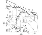
図1は、トランクヒンジが取り付けられた右側の車体後部を、ルーフパネル等を外して示す斜視図で、図2はそのX部分の拡大図である。
1は右側の車体側部を構成するサイドボディパネルで、図示しないフロントドアおよびリヤドアを取り付けるドア開口部1a,1bが設けられている。リヤドアを取り付けるドア開口部1bの後部側には、上方にクォーターピラーインナパネル2が、下方にホイールハウス3が設けられている。車室内側壁となるクォーターピラーインナパネル2の室内側には、シートベルトリンフォース4とリヤピラーインナリンフォース5が上下に設けられている。
Hereinafter, the present invention is a notchback type vehicle having a trunk room at the rear of the vehicle body, and is applied to the rear vehicle body of the vehicle in which the left and right ends of the partition portion that separates the vehicle interior and the trunk room are connected and fixed to the side wall portion of the vehicle interior. The embodiment of the above will be described in detail with reference to FIGS. 1 to 7.
FIG. 1 is a perspective view showing the rear portion of the vehicle body on the right side to which the trunk hinge is attached, with the roof panel and the like removed, and FIG. 2 is an enlarged view of the X portion thereof.
前記サイドボディパネル1は、図示しない左側のサイドボディパネルと共に、車室内となるキャビン6を構成するもので、このキャビン6の後方に、荷物入れとなるトランクルーム7が設けられる。このトランクルーム7は車幅方向に設けられるパーティション部8によって、キャビン6と仕切られており、トランクルーム7の上面は、開閉可能なトランクリッド9によって外部と仕切られる。
The
前記パーティション部8は、パーティション前壁部81と、パーティション上壁部82と、パーティション横壁部83とで構成されている。前記パーティション前壁部81は、図2および図7に示すように、車幅方向に延びる帯状のパーティションフロントメンバ10と、このパーティションフロントメンバ10の前方に設けられ、車体前後方向に前面壁部11aから上面部11bにかけて屈曲して形成され、かつ車幅方向に延びるパーティションフロントパネル11とで構成されている。パーティションフロントメンバ10はパーティションフロントパネル11の前面壁部11aの裏面側に車幅方向に図示しない間隙を設けて接合されており、車幅方向に閉じ断面構造を形成している。
パーティション上壁部82は、パーティションフロントパネル11の後方側に接合されたパーティションパネル12と、パーティションパネル12の後部側に接合されたパーティションリヤメンバ13とで構成されている。パーティションパネル12の後端部には、パーティションリヤメンバ13との間に図示しない間隙を形成して、車幅方向に閉じ断面構造を形成している。
The
Partition the upper wall portion 82 includes a
一方、パーティション横壁部83は、パーティション前壁部81と、パーティション上壁部82のうち、両者の車幅方向両端周辺の部位であり、両者に跨るように接合して設けられた、パーティションサイドフロントパネル14と、パーティションサイドリヤパネル15とで構成されている。パーティション横壁部83の上面、パーティションサイドリヤパネル15には、トランクリッド9を開閉するドッグレッグ式のトランクヒンジ16のヒンジブラケット17が設けられている。パーティションサイドリヤパネル15には、上面にヒンジブラケット用開口部15aが設けられている。このヒンジブラケット用開口部15aには、図3および図4に示すように、ヒンジブラケット17の左右両側の取付フランジ部17aが通されて、パーティションサイドリヤパネル15の裏面側に取付フランジ部17aが重ねられて、図示しない取付孔を通してボルト18およびナット18aを介して螺着されている。ボルト18およびナット18aは、車体内側の取付フランジ部17aでは2個所、車体外側の取付フランジ部17aでは1個所に設けられて固定されている。ドッグレッグ式のトランクヒンジ16は一端部がヒンジブラケット17に軸支されており、他端部がトランクリッド9の裏面側に固定されている。
On the other hand, the partition
前記パーティションサイドリヤパネル15は、図4に示すように、車幅方向の側壁側に下方に向けた段差部15bが形成されており、段差部15bの先を下方に延設して、その車幅方向の先端部15cが前記クォーターピラーインナパネル2およびリヤピラーインナリンフォース5に接合されている。前記パーティションサイドリヤパネル15の段差部15bの上部側にはパネル状の補強部材19が配置されて、パーティションサイドリヤパネル15と、補強部材19と、前記リヤピラーインナリンフォース5とで車室内側壁部の前後方向に沿って一定長さの閉じ断面Sが形成されている。
As shown in FIG. 4, the partition side
前記閉じ断面Sは、図5および図7に示すようにパーティション前壁部81では、パーティションサイドフロントパネル14と、パーティションサイドフロントメンバ14aと、リヤピラーインナリンフォース5(車室内側壁部)とで第1の閉じ断面(前部閉じ断面)S1が形成されている。次に閉じ断面Sは、上壁部82では、補強部材19と、パーティションサイドリヤパネル15と、リヤピラーインナリンフォース(車室内側壁部)5とで第2の閉じ断面(側部閉じ断面)S2が形成されている。閉じ断面Sは、上壁部82では、パーティションリヤメンバ13と、パーティションサイドリヤパネル15と、クォーターピラー部等(車室内側壁部)とで第3の閉じ断面S3が形成されている。第2の閉じ断面S2と第3の閉じ断面(後部閉じ断面)S3は、図5の実施形態では繋がっているが、仕切り壁を設けることで、完全に分離することもできる。
Said closed cross-section S is de Partition front wall portion 81 as shown in FIGS. 5 and 7, the partition
上記実施の形態では、車体後部にトランクルーム7を持つノッチバックタイプの車両であって、車室内となるキャビン6とトランクルーム7とを仕切るパーティション部8の左右両端部が車室内側壁部に接続固定されている車両の後部車体構造に適用したものである。そして、前記パーティション部8の両端部に、車両の前後方向に沿って閉じ断面構造Sを設けたので、接合部の剛性を向上させ、車体の捩じれ剛性を向上させることができる。
In the above embodiment, the vehicle is a notchback type vehicle having a
また、前記パーティション部8の上壁部82にはヒンジブラケット17の取付部であるトランクヒンジ取付部が設けられており、クォーターピラーインナパネル2側の前記パーティション部8端部には、ヒンジブラケット17の取付け面に対して下側に下がる段差部15bが設けられている。そして前記段差部15bの上に前記クォーターピラーインナパネル(側壁部)2に向けて補強部材19が設けられ、前記パーティション部8の段差部15bとの間に車体の前後方向に沿った閉じ断面S構造が設けられている。こうして、ヒンジブラケット17の取付け面より下側に段差部15bを有することで、トランクリッド9の取付による下向きの荷重に対するパーティション部8の端部の垂れ下がり等の変形を支えやすくなり、組み付け品質の向上になる。また、補強部材19を追加することで、パーティションサイドリヤパネル15とクォーターピラーインナパネル2およびリヤピラーインナリンフォース5の接合点を閉じ断面部Sを挟んで、上下方向に離して複数配置することにより、車体の捩じれによる変形などによる車両上下方向の入力で、接合点に応力集中するのを防ぐことができ、接合強度を高めることができる。さらに、パーティション部8の端部を閉じ断面構造によって補強することで、接合部の変形を抑えることができ、車体の捩じれ自体を低減することができる。
Further, the
ヒンジブラケット17の取付部であるトランクヒンジ取付部は、閉じ断面S構造に隣接して設けられており、トランクヒンジ取付部の少なくとも閉じ断面構造側の固定部は、前記パーティション部8のパーティションサイドリヤパネル15、補強部材19と共締め固定されている。したがって、トランクヒンジ取付部を補強部材19と閉じ断面構造によって剛性の向上を図ることができるので、走行振動などのよるトランクリッド9の振動を低減することができる。トランクリッド9の開閉時におけるトランクリッド9の搖動やオーバーストロークも抑えることができるため、トランクリッド9と車体の隙間を小さくすることで、見切りを良くすることができ、品質向上につながる。トランクリッド9の取付剛性が向上するため、トランクリッド9の振動に起因する異音などの発生を低減することができる。
The trunk hinge mounting portion, which is the mounting portion of the
前記車室内側壁部は、ホイールハウス3のショックアブソーバ取付部から上方向に延びるリヤピラーインナリンフォース5を含んで構成され、前記パーティション部8のパーティションサイドフロントパネル14およびパーティションサイドリヤパネル15からなるパーティションサイドパネルと、前記補強部材19とで構成される側部閉じ断面S構造の前部が前記リヤピラーインナリンフォース5に連続して設けられている。したがって、ホイールハウス3のサスペンションのショックアブソーバ取付部から剛性の高い構造を連続させることで、走行時のサスペンションからの入力に対して車体の剛性を高めることができ、車体を変形しにくくすることができる。
The vehicle interior side wall portion is configured to include a rear pillar
前記車室内側壁部は、クォーターピラーインナパネル2、リヤピラーインナリンフォース5、リヤシートベルトリンフォース4を含んで構成され、リヤピラーインナリンフォース5とリヤシートベルトリンフォース4とが前記補強部材19と共止め固定されている。よって、接合部の強度を向上させることができ、より変形を抑えることができる。接合部に発生する応力を、クォーターピラーインナパネル2を通り、サイドボディ1に逃がすことで、接合部に応力が集中することを防ぐことができる。
The vehicle interior side wall portion includes a quarter pillar
なお、本発明は、上記の実施の形態のみに限定されるものではなく、例えば、補強部材19とパーティションサイドリヤパネル15とでパーティション部8の閉じ断面Sを形成しているが、補強部材19の形状を車体方向に長尺のものを用いることで、パーティション横壁部83の全体を補強部材で補強することができる。また、トランクヒンジ取付部の全体を補強部材19で覆うことで、より剛性の向上を図ることができる。等本発明の技術的範囲を変更することなく適宜変更して実施しうることは言うまでもない。
The present invention is not limited to the above embodiment. For example, the reinforcing
1 サイドボディパネル
2 クォーターピラーインナパネル
3 ホイールハウス
4 シートベルトリンフォース
5 リヤピラーインナリンフォース
6 キャビン
7 トランクルーム
8 パーティション部
81 パーティション前壁部
82 パーティション上壁部
83 パーティション横壁部
9 トランクリッド
10 パーティションフロントメンバ
11 パーティションフロントパネル
12 パーティションパネル
13 パーティションリヤメンバ
14 パーティションサイドフロントパネル
14a パーティションサイドフロントメンバ
15 パーティションサイドリヤパネル
15a ヒンジブラケット用開口部
15b 段差部
15c 先端部
16 トランクヒンジ
17 ヒンジブラケット
17a 取付フランジ部
18 ボルト
18a ナット
19 補強部材
S 閉じ断面
S1 第1の閉じ断面(前部閉じ断面)
S2 第2の閉じ断面(側部閉じ断面)
S3 第3の閉じ断面(後部閉じ断面)
1
14a Partition
S 2 Second closed cross section (side closed cross section)
S 3 Third closed cross section (rear closed cross section)
Claims (5)
車室内とトランクルームとを仕切るパーティション部と、
前記パーティション部の端部が接続固定される車室内側壁部と、を備え、
前記端部に、車両の前後方向に沿って閉じ断面構造が形成される車両の後部車体構造において、
前記車室内側壁部は、ホイールハウスのショックアブソーバ取付部から上方向に延びるリヤピラーインナリンフォースを有し、
前記リヤピラーインナリンフォースが前記閉じ断面構造の一部を構成することを特徴とする車両の後部車体構造。 A vehicle that has a trunk room at the rear of the vehicle.
The partition that separates the passenger compartment from the trunk room ,
The vehicle interior side wall portion to which the end portion of the partition portion is connected and fixed is provided.
In the rear body structure of a vehicle in which a closed cross-sectional structure is formed at the end portion along the front-rear direction of the vehicle.
The vehicle interior side wall portion has a rear pillar inner force that extends upward from the shock absorber mounting portion of the wheel house.
A rear body structure of a vehicle, wherein the rear pillar inner force forms a part of the closed cross-sectional structure.
トランクヒンジ取付部が設けられる上壁部と、
前記上壁部の前記車室内側壁部側に設けられ、前記トランクヒンジ取付部の取付け面に対して下側に下がる段差部と、を有し、
前記段差部の上に前記取付け面に沿って前記車室内側壁部に伸びて前記車室内側壁部に接続される補強部材を備えることを特徴とする請求項1に記載の車両の後部車体構造。 The partition part is
An upper wall portion of the trunk hinge attachment portion Ru provided,
It has a stepped portion provided on the side wall portion of the vehicle interior of the upper wall portion and lowered to the lower side with respect to the mounting surface of the trunk hinge mounting portion.
Rear vehicle body structure according to claim 1, characterized in that it comprises a reinforcing member connected to the passenger compartment side wall portion extending in the vehicle compartment side wall portion along the mounting surface on the step portion.
前記上壁部に跨るように接合され、前記取付け面よりも後方に伸びる横壁部を有し、
前記閉じ断面構造の後方に位置して、前記横壁部、前記補強部材、および前記リヤピラーインナリンフォースによって後方側の閉じ断面構造が形成されることを特徴とする請求項2に記載の車両の後部車体構造。 The partition part is
It has a lateral wall portion that is joined so as to straddle the upper wall portion and extends rearward from the mounting surface.
The rear portion of the vehicle according to claim 2, wherein a closed cross-sectional structure on the rear side is formed by the lateral wall portion, the reinforcing member, and the rear pillar inner line force, which is located behind the closed cross-section structure. Body structure.
前記上壁部に跨るように接合される横壁部を有し、
前記上壁部が、前記閉じ断面構造よりも下方に形成された下方側の閉じ断面構造から下方に伸びて前記リヤピラーインナリンフォースに接続されている請求項2または3に記載の車両の後部車体構造。 The partition part is
It has a lateral wall portion that is joined so as to straddle the upper wall portion.
The rear vehicle body of the vehicle according to claim 2 or 3, wherein the upper wall portion extends downward from the lower closed cross-section structure formed below the closed cross-section structure and is connected to the rear pillar inner ring force. Construction.
車室内とトランクルームとを仕切るパーティション部と、
前記パーティション部の端部が接続固定される車室内側壁部と、を備え、
前記端部に、車両の前後方向に沿って閉じ断面構造が形成され、
前記車室内側壁部は、リヤシートベルトリンフォースを含んで構成され、
前記リヤシートベルトリンフォースと補強部材とが共止め固定されていることを特徴とする車両の後部車体構造。 A vehicle that has a trunk room at the rear of the vehicle.
The partition that separates the passenger compartment from the trunk room,
The vehicle interior side wall portion to which the end portion of the partition portion is connected and fixed is provided.
A closed cross-sectional structure is formed at the end along the front-rear direction of the vehicle.
The side wall of the vehicle interior includes a rear seat belt reinforcement.
Rear vehicle body structure of a vehicle, characterized in that said rear seat belt reinforcement and reinforcement member are co-fastened.
Priority Applications (1)
| Application Number | Priority Date | Filing Date | Title |
|---|---|---|---|
| JP2017073793A JP6876270B2 (en) | 2017-04-03 | 2017-04-03 | Rear body structure of the vehicle |
Applications Claiming Priority (1)
| Application Number | Priority Date | Filing Date | Title |
|---|---|---|---|
| JP2017073793A JP6876270B2 (en) | 2017-04-03 | 2017-04-03 | Rear body structure of the vehicle |
Publications (3)
| Publication Number | Publication Date |
|---|---|
| JP2018176786A JP2018176786A (en) | 2018-11-15 |
| JP2018176786A5 JP2018176786A5 (en) | 2020-03-26 |
| JP6876270B2 true JP6876270B2 (en) | 2021-05-26 |
Family
ID=64281830
Family Applications (1)
| Application Number | Title | Priority Date | Filing Date |
|---|---|---|---|
| JP2017073793A Active JP6876270B2 (en) | 2017-04-03 | 2017-04-03 | Rear body structure of the vehicle |
Country Status (1)
| Country | Link |
|---|---|
| JP (1) | JP6876270B2 (en) |
Families Citing this family (1)
| Publication number | Priority date | Publication date | Assignee | Title |
|---|---|---|---|---|
| KR102200087B1 (en) * | 2018-12-11 | 2021-01-07 | 현대자동차주식회사 | Frame joint |
Family Cites Families (2)
| Publication number | Priority date | Publication date | Assignee | Title |
|---|---|---|---|---|
| JPH06255537A (en) * | 1993-03-05 | 1994-09-13 | Nissan Motor Co Ltd | Body structure of automobile |
| JP5598170B2 (en) * | 2010-08-30 | 2014-10-01 | スズキ株式会社 | Partition side structure |
-
2017
- 2017-04-03 JP JP2017073793A patent/JP6876270B2/en active Active
Also Published As
| Publication number | Publication date |
|---|---|
| JP2018176786A (en) | 2018-11-15 |
Similar Documents
| Publication | Publication Date | Title |
|---|---|---|
| JP7081533B2 (en) | Rear body structure of the vehicle | |
| JP6304066B2 (en) | Upper body structure of the vehicle | |
| CN111619677B (en) | Rear body structure of vehicle | |
| US11192591B2 (en) | Vehicle body structure of vehicle | |
| JP2008230518A (en) | Rear part vehicle body structure for vehicle | |
| EP3712042B1 (en) | Vehicle body structure of vehicle | |
| KR102371245B1 (en) | Center pillar structure for vehicle | |
| JP3866176B2 (en) | Body structure | |
| JP6137205B2 (en) | Rear body structure of automobile | |
| JP2020168962A (en) | Side part vehicle body structure of vehicle | |
| JP7065134B2 (en) | Vehicle door | |
| JP6876270B2 (en) | Rear body structure of the vehicle | |
| JP7347242B2 (en) | Vehicle rear body structure | |
| JP2009184403A (en) | Vehicle front body structure | |
| JP6280413B2 (en) | Body structure | |
| JP7147395B2 (en) | vehicle rear body structure | |
| JP4715039B2 (en) | Vehicle side body structure | |
| JP2018176786A5 (en) | ||
| JP2013139169A (en) | Vehicle rear structure | |
| JP2011098684A (en) | Upper vehicle body structure of vehicle | |
| JP2021000936A (en) | Vehicle body rear part structure | |
| JP4924628B2 (en) | Vehicle side door structure | |
| JP3967836B2 (en) | Rear body structure of the vehicle | |
| JPH01186481A (en) | Car body structure of automobile | |
| KR20230139222A (en) | Vehicle rear strucutre |
Legal Events
| Date | Code | Title | Description |
|---|---|---|---|
| A621 | Written request for application examination |
Free format text: JAPANESE INTERMEDIATE CODE: A621 Effective date: 20200207 |
|
| A521 | Written amendment |
Free format text: JAPANESE INTERMEDIATE CODE: A523 Effective date: 20200210 |
|
| A131 | Notification of reasons for refusal |
Free format text: JAPANESE INTERMEDIATE CODE: A131 Effective date: 20200911 |
|
| A977 | Report on retrieval |
Free format text: JAPANESE INTERMEDIATE CODE: A971007 Effective date: 20200910 |
|
| A601 | Written request for extension of time |
Free format text: JAPANESE INTERMEDIATE CODE: A601 Effective date: 20201109 |
|
| A521 | Written amendment |
Free format text: JAPANESE INTERMEDIATE CODE: A523 Effective date: 20201225 |
|
| TRDD | Decision of grant or rejection written | ||
| A01 | Written decision to grant a patent or to grant a registration (utility model) |
Free format text: JAPANESE INTERMEDIATE CODE: A01 Effective date: 20210326 |
|
| A61 | First payment of annual fees (during grant procedure) |
Free format text: JAPANESE INTERMEDIATE CODE: A61 Effective date: 20210408 |
|
| R151 | Written notification of patent or utility model registration |
Ref document number: 6876270 Country of ref document: JP Free format text: JAPANESE INTERMEDIATE CODE: R151 |