JP6875552B2 - End control device, end control device, transportation device and assembly case - Google Patents
End control device, end control device, transportation device and assembly case Download PDFInfo
- Publication number
- JP6875552B2 JP6875552B2 JP2019560289A JP2019560289A JP6875552B2 JP 6875552 B2 JP6875552 B2 JP 6875552B2 JP 2019560289 A JP2019560289 A JP 2019560289A JP 2019560289 A JP2019560289 A JP 2019560289A JP 6875552 B2 JP6875552 B2 JP 6875552B2
- Authority
- JP
- Japan
- Prior art keywords
- sheath
- elastic
- limiting
- connecting pipe
- passage
- Prior art date
- Legal status (The legal status is an assumption and is not a legal conclusion. Google has not performed a legal analysis and makes no representation as to the accuracy of the status listed.)
- Active
Links
Images


Classifications
-
- A—HUMAN NECESSITIES
- A61—MEDICAL OR VETERINARY SCIENCE; HYGIENE
- A61B—DIAGNOSIS; SURGERY; IDENTIFICATION
- A61B17/00—Surgical instruments, devices or methods
- A61B17/12—Surgical instruments, devices or methods for ligaturing or otherwise compressing tubular parts of the body, e.g. blood vessels or umbilical cord
- A61B17/122—Clamps or clips, e.g. for the umbilical cord
- A61B17/1227—Spring clips
-
- A—HUMAN NECESSITIES
- A61—MEDICAL OR VETERINARY SCIENCE; HYGIENE
- A61B—DIAGNOSIS; SURGERY; IDENTIFICATION
- A61B17/00—Surgical instruments, devices or methods
- A61B17/12—Surgical instruments, devices or methods for ligaturing or otherwise compressing tubular parts of the body, e.g. blood vessels or umbilical cord
- A61B17/122—Clamps or clips, e.g. for the umbilical cord
-
- A—HUMAN NECESSITIES
- A61—MEDICAL OR VETERINARY SCIENCE; HYGIENE
- A61B—DIAGNOSIS; SURGERY; IDENTIFICATION
- A61B17/00—Surgical instruments, devices or methods
- A61B17/12—Surgical instruments, devices or methods for ligaturing or otherwise compressing tubular parts of the body, e.g. blood vessels or umbilical cord
- A61B17/128—Surgical instruments, devices or methods for ligaturing or otherwise compressing tubular parts of the body, e.g. blood vessels or umbilical cord for applying or removing clamps or clips
- A61B17/1285—Surgical instruments, devices or methods for ligaturing or otherwise compressing tubular parts of the body, e.g. blood vessels or umbilical cord for applying or removing clamps or clips for minimally invasive surgery
-
- A—HUMAN NECESSITIES
- A61—MEDICAL OR VETERINARY SCIENCE; HYGIENE
- A61B—DIAGNOSIS; SURGERY; IDENTIFICATION
- A61B17/00—Surgical instruments, devices or methods
- A61B17/28—Surgical forceps
- A61B17/29—Forceps for use in minimally invasive surgery
-
- A—HUMAN NECESSITIES
- A61—MEDICAL OR VETERINARY SCIENCE; HYGIENE
- A61B—DIAGNOSIS; SURGERY; IDENTIFICATION
- A61B17/00—Surgical instruments, devices or methods
- A61B17/12—Surgical instruments, devices or methods for ligaturing or otherwise compressing tubular parts of the body, e.g. blood vessels or umbilical cord
- A61B17/122—Clamps or clips, e.g. for the umbilical cord
- A61B17/1222—Packages or dispensers therefor
-
- A—HUMAN NECESSITIES
- A61—MEDICAL OR VETERINARY SCIENCE; HYGIENE
- A61B—DIAGNOSIS; SURGERY; IDENTIFICATION
- A61B17/00—Surgical instruments, devices or methods
- A61B2017/00477—Coupling
-
- A—HUMAN NECESSITIES
- A61—MEDICAL OR VETERINARY SCIENCE; HYGIENE
- A61B—DIAGNOSIS; SURGERY; IDENTIFICATION
- A61B17/00—Surgical instruments, devices or methods
- A61B2017/00526—Methods of manufacturing
- A61B2017/0053—Loading magazines or sutures into applying tools
-
- A—HUMAN NECESSITIES
- A61—MEDICAL OR VETERINARY SCIENCE; HYGIENE
- A61B—DIAGNOSIS; SURGERY; IDENTIFICATION
- A61B17/00—Surgical instruments, devices or methods
- A61B17/12—Surgical instruments, devices or methods for ligaturing or otherwise compressing tubular parts of the body, e.g. blood vessels or umbilical cord
- A61B2017/12004—Surgical instruments, devices or methods for ligaturing or otherwise compressing tubular parts of the body, e.g. blood vessels or umbilical cord for haemostasis, for prevention of bleeding
Landscapes
- Health & Medical Sciences (AREA)
- Surgery (AREA)
- Life Sciences & Earth Sciences (AREA)
- Heart & Thoracic Surgery (AREA)
- Molecular Biology (AREA)
- Veterinary Medicine (AREA)
- Engineering & Computer Science (AREA)
- Biomedical Technology (AREA)
- Public Health (AREA)
- Medical Informatics (AREA)
- Nuclear Medicine, Radiotherapy & Molecular Imaging (AREA)
- Animal Behavior & Ethology (AREA)
- General Health & Medical Sciences (AREA)
- Reproductive Health (AREA)
- Vascular Medicine (AREA)
- Ophthalmology & Optometry (AREA)
- Surgical Instruments (AREA)
- Quick-Acting Or Multi-Walled Pipe Joints (AREA)
- Infusion, Injection, And Reservoir Apparatuses (AREA)
Description
本発明は、医療機器分野に属し、具体的に、端部操作機器、端部操作装置、輸送装置及び組み立てケースに関する。 The present invention belongs to the medical device field, and specifically relates to an end operation device, an end operation device, a transportation device, and an assembly case.
臨床においては、常に、内視鏡をクリップ機械と組み合わせて利用して押さえつけて止血する方法で治療を行う。現在、臨床で使用されている端部操作装置は、クリップと装置の分離式(「分離式端部操作装置」と略称される)又はクリップと装置の一体式(「一体式端部操作装置」と略称される)に分けられる。 In clinical practice, treatment is always performed by using an endoscope in combination with a clip machine to hold it down to stop bleeding. Currently, the end operating device used in clinical practice is a clip and device separated type (abbreviated as "separable end operating device") or a clip and device integrated type ("integrated end operating device"). (Abbreviated as).
分離式端部操作装置のクリップ部分は、使い捨てのものである。この装置部分は、繰り返し使用可能なものであるため、コストを節約し、医療ゴミを減少することができ、安価で環境にやさしいが、臨床的に使用されている分離式端部操作装置は使用時に操作しにくく、クリップ部分が閉じると再び開くことができず、繰り返し開閉できない。一体式端部操作装置は繰り返し開閉を実現できるが、そのクリップ部分及び装置部分がいずれも使い捨てのものであるため、コストがより高く、医療ゴミも多い。 The clip portion of the separable end operating device is disposable. This device part is reusable, which saves cost, reduces medical waste, is cheap and environmentally friendly, but uses the clinically used separable end manipulator. Sometimes it is difficult to operate, and when the clip part is closed, it cannot be opened again and cannot be opened and closed repeatedly. The integrated end operating device can be repeatedly opened and closed, but since both the clip portion and the device portion are disposable, the cost is higher and there is a large amount of medical waste.
従って、繰り返し開閉を実現でき、コストがより低く、装置部分を繰り返し使用できて、クリップ部分及び装置部分をより容易且つ安全に取り付けることのできる端部操作装置を必要としている。 Therefore, there is a need for an end operating device that can be opened and closed repeatedly, is less costly, can use the device portion repeatedly, and can more easily and safely attach the clip portion and the device portion.
これに基づき、本発明は従来技術の欠点を解決するために、端部操作装置のクリップを繰り返し操作でき、輸送装置を繰り返し使用できる端部操作機器、端部操作装置、輸送装置及び組み立てケースを提供する。 Based on this, in order to solve the drawbacks of the prior art, the present invention provides an end operating device, an end operating device, a transport device and an assembly case capable of repeatedly operating the clip of the end operating device and repeatedly using the transport device. provide.
その技術案は以下のとおりである。 The technical proposal is as follows.
端部操作機器であって、クリップ及び弾性部を備え、前記弾性部に外嵌孔が設けられ、前記弾性部に制限凸部が設けられる端部操作装置と、シース及び心軸を備え、前記シースに通路が設けられ、前記心軸が前記シースの通路内に設けられ、前記心軸の遠位端に接続先端が設けられ、前記シースに制限凹部が設けられる輸送装置と、を備え、前記シースが前記弾性部の外部に被装される場合、前記接続先端が前記外嵌孔に伸び込み又は前記外嵌孔を離れることができ、前記接続先端が前記外嵌孔に伸び込まれる場合、前記弾性部が外向きに拡張し、前記制限凸部が前記制限凹部に伸び込まれ、前記接続先端が前記外嵌孔を離れる場合、前記弾性部が反発し、前記制限凸部が前記制限凹部を離れる。 An end operating device comprising an end operating device including a clip and an elastic portion, an outer fitting hole provided in the elastic portion, and a limiting convex portion provided in the elastic portion, and a sheath and a core shaft. The sheath is provided with a passage, the core axis is provided in the passage of the sheath, a connection tip is provided at the distal end of the core axis, and the sheath is provided with a limiting recess. When the sheath is placed on the outside of the elastic portion, the connection tip can extend into or leave the outer fitting hole, and the connection tip extends into the outer fitting hole. When the elastic portion expands outward, the limiting convex portion extends into the limiting concave portion, and the connection tip leaves the outer fitting hole, the elastic portion repels and the limiting convex portion becomes the limiting concave portion. Leave.
一実施例では、前記制限凸部が少なくとも2つである。 In one embodiment, there are at least two limiting protrusions.
一実施例では、前記端部操作装置が更に接続管を備え、前記クリップが前記接続管に取り付けられ、前記接続管に通路が設けられ、前記弾性部が弾性リングを備え、前記弾性リングが前記接続管の通路内に設けられ、前記弾性リングに前記外嵌孔及び前記制限凸部が設けられ、前記外嵌孔が前記接続管の通路に連通しており、前記接続管の管壁に制限孔が設けられ、前記制限孔が前記制限凸部に対応する。 In one embodiment, the end operating device further comprises a connecting tube, the clip is attached to the connecting tube, the connecting tube is provided with a passage, the elastic portion is provided with an elastic ring, and the elastic ring is said. Provided in the passage of the connecting pipe, the elastic ring is provided with the outer fitting hole and the limiting convex portion, and the outer fitting hole communicates with the passage of the connecting pipe and is restricted to the pipe wall of the connecting pipe. A hole is provided, and the limiting hole corresponds to the limiting convex portion.
一実施例では、前記弾性リングに欠け口が設けられる。 In one embodiment, the elastic ring is provided with a chip.
一実施例では、前記クリップの近位端が前記接続管の通路に伸び込まれ、前記クリップの近位端に係着孔が設けられ、前記係着孔が前記接続管の通路に連通しており、前記接続先端の遠位端に係着部が設けられ、前記係着部が前記係着孔に係合され、前記係着部が凹溝部及び膨大部を備え、前記凹溝部が前記膨大部と前記接続先端との間に位置し、前記膨大部の最大幅が前記凹溝部の最小幅より大きく、前記膨大部の最大幅が前記係着孔の最小幅より大きい。 In one embodiment, the proximal end of the clip extends into the passage of the connecting pipe, an anchoring hole is provided at the proximal end of the clip, and the anchoring hole communicates with the passage of the connecting pipe. An engagement portion is provided at the distal end of the connection tip, the engagement portion is engaged with the engagement hole, the engagement portion includes a concave groove portion and a huge portion, and the concave groove portion is the huge portion. Located between the portion and the connection tip, the maximum width of the bulging portion is larger than the minimum width of the concave groove portion, and the maximum width of the bulging portion is larger than the minimum width of the engaging hole.
一実施例では、前記膨大部の遠位端に案内部が設けられ、前記案内部の横断面が近位端から遠位端へ徐々に減少する。 In one embodiment, a guide is provided at the distal end of the ampulla, and the cross section of the guide gradually decreases from the proximal end to the distal end.
一実施例では、前記クリップが少なくとも2つの挟持片を備え、前記挟持片の近位端に後部挟持部が設けられ、少なくとも2つの前記後部挟持部の間に隙間が設けられ、少なくとも2つの前記後部挟持部の間の隙間が前記係着孔をなす。 In one embodiment, the clip comprises at least two holding pieces, a rear holding portion is provided at the proximal end of the holding piece, a gap is provided between the at least two rear holding pieces, and at least two of the said. The gap between the rear holding portions forms the engagement hole.
一実施例では、前記端部操作装置が更に接続管を備え、前記クリップが前記接続管に取り付けられ、前記接続管に通路が設けられ、前記弾性部がハーフリングを備え、前記ハーフリングが前記接続管の通路内に設けられ、前記ハーフリングの一方側に前記制限凸部が設けられ、前記ハーフリングの他方側と前記接続管の内壁との間が前記外嵌孔をなす。 In one embodiment, the end operating device further comprises a connecting tube, the clip is attached to the connecting tube, the connecting tube is provided with a passage, the elastic portion is provided with a halfling, and the halfling is said. It is provided in the passage of the connecting pipe, the limiting convex portion is provided on one side of the half ring, and the outer fitting hole is formed between the other side of the half ring and the inner wall of the connecting pipe.
一実施例では、前記制限凸部の側面に制限部が設けられ、前記制限部が前記接続管の通路内に位置する。 In one embodiment, a limiting portion is provided on the side surface of the limiting convex portion, and the limiting portion is located in the passage of the connecting pipe.
一実施例では、前記弾性リングが少なくとも2つのハーフリングを備え、少なくとも2つの前記ハーフリングの間が前記外嵌孔に囲まれ、前記ハーフリングに前記制限凸部が設けられる。 In one embodiment, the elastic ring comprises at least two halflings, the space between the at least two halflings is surrounded by the outer fitting hole, and the halfling is provided with the limiting convex portion.
端部操作機器であって、接続管及び前記接続管に取り付けられるクリップを備え、前記接続管に通路が設けられ、前記接続管の内壁に制限凹部が設けられる端部操作装置と、シース及び心軸を備え、前記シースに通路が設けられ、前記心軸が前記シースの通路内に設けられ、前記心軸の遠位端に接続先端が設けられ、前記シースの遠位端に弾性部が設けられ、前記弾性部に外嵌孔が設けられ、前記外嵌孔が前記シースの通路に連通しており、前記弾性部に制限凸部が設けられる輸送装置と、を備え、前記弾性部が前記接続管の通路に伸び込まれる場合、前記接続先端が前記外嵌孔に伸び込み又は前記外嵌孔を離れることができ、前記接続先端が前記外嵌孔に伸び込まれる場合、前記弾性部を押し出して外向きに拡張させ、前記制限凸部が前記制限凹部に伸び込まれ、前記接続先端が前記外嵌孔を離れる場合、前記弾性部が反発し、前記制限凸部が前記制限凹部を離れる。 An end operating device that includes a connecting pipe and a clip attached to the connecting pipe, a passage is provided in the connecting pipe, and a limiting recess is provided in the inner wall of the connecting pipe, and a sheath and a core. A shaft is provided, a passage is provided in the sheath, the core shaft is provided in the passage of the sheath, a connection tip is provided at the distal end of the core shaft, and an elastic portion is provided at the distal end of the sheath. The elastic portion is provided with an outer fitting hole, the outer fitting hole communicates with the passage of the sheath, and the elastic portion is provided with a limiting convex portion. When extending into the passage of the connecting pipe, the connecting tip can extend into or leave the outer fitting hole, and when the connecting tip extends into the outer fitting hole, the elastic portion is stretched. When it is extruded and expanded outward, the limiting convex portion extends into the limiting concave portion, and the connection tip leaves the outer fitting hole, the elastic portion repels and the limiting convex portion leaves the limiting concave portion. ..
一実施例では、前記制限凸部が少なくとも2つである。 In one embodiment, there are at least two limiting protrusions.
一実施例では、前記弾性部が弾性リングを備え、前記弾性リングが前記シースの遠位端に設けられ、前記弾性リングが前記シースの通路内に設けられ、前記弾性リングに前記外嵌孔及び前記制限凸部が設けられ、前記シースの管壁に制限孔が設けられ、前記制限孔が前記制限凸部に対応する。 In one embodiment, the elastic portion comprises an elastic ring, the elastic ring is provided at the distal end of the sheath, the elastic ring is provided in the passage of the sheath, and the elastic ring is provided with the outer fitting hole and the outer fitting hole. The limiting convex portion is provided, a limiting hole is provided in the tube wall of the sheath, and the limiting hole corresponds to the limiting convex portion.
一実施例では、前記弾性リングに欠け口が設けられる。 In one embodiment, the elastic ring is provided with a chip.
一実施例では、前記クリップの近位端が前記接続管の通路に伸び込まれ、前記クリップの近位端に係着孔が設けられ、前記係着孔が前記接続管の通路に連通しており、前記接続先端の遠位端に係着部が設けられ、前記係着部が前記係着孔に係合され、前記係着部が凹溝部及び膨大部を備え、前記凹溝部が前記膨大部と前記接続先端との間に位置し、前記膨大部の最大幅が前記凹溝部の最小幅より大きく、前記膨大部の最大幅が前記係着孔の最小幅より大きい。 In one embodiment, the proximal end of the clip extends into the passage of the connecting pipe, an anchoring hole is provided at the proximal end of the clip, and the anchoring hole communicates with the passage of the connecting pipe. An engagement portion is provided at the distal end of the connection tip, the engagement portion is engaged with the engagement hole, the engagement portion includes a concave groove portion and a huge portion, and the concave groove portion is the huge portion. Located between the portion and the connection tip, the maximum width of the bulging portion is larger than the minimum width of the concave groove portion, and the maximum width of the bulging portion is larger than the minimum width of the engaging hole.
一実施例では、前記膨大部の遠位端に案内部が設けられ、前記案内部の横断面が近位端から遠位端へ徐々に減少する。 In one embodiment, a guide is provided at the distal end of the ampulla, and the cross section of the guide gradually decreases from the proximal end to the distal end.
一実施例では、前記クリップが少なくとも2つの挟持片を備え、前記挟持片の近位端に後部挟持部が設けられ、少なくとも2つの前記後部挟持部の間に隙間が設けられ、少なくとも2つの前記後部挟持部の間の隙間が前記係着孔をなす。 In one embodiment, the clip comprises at least two holding pieces, a rear holding portion is provided at the proximal end of the holding piece, a gap is provided between the at least two rear holding pieces, and at least two of the said. The gap between the rear holding portions forms the engagement hole.
一実施例では、前記弾性部がハーフリングを備え、前記ハーフリングが前記接続管の通路内に設けられ、前記ハーフリングの一方側に前記制限凸部が設けられ、前記ハーフリングの他方側と前記接続管の内壁との間が前記外嵌孔をなす。 In one embodiment, the elastic portion comprises a halfling, the halfling is provided in the passage of the connecting pipe, the limiting convex portion is provided on one side of the halfling, and the other side of the halfling. The outer fitting hole is formed between the connecting pipe and the inner wall.
一実施例では、前記制限凸部の側面に制限部が設けられ、前記制限部が前記シースの通路内に位置する。 In one embodiment, a limiting portion is provided on the side surface of the limiting convex portion, and the limiting portion is located in the passage of the sheath.
一実施例では、前記弾性リングが少なくとも2つのハーフリングを備え、少なくとも2つの前記ハーフリングの間が前記外嵌孔に囲まれ、前記ハーフリングに前記制限凸部が設けられる。 In one embodiment, the elastic ring comprises at least two halflings, the space between the at least two halflings is surrounded by the outer fitting hole, and the halfling is provided with the limiting convex portion.
端部操作装置であって、クリップ及び前記クリップにドッキングされる弾性部を備え、前記弾性部に外嵌孔が設けられ、前記弾性部に制限凸部が設けられ、前記弾性部が前記外嵌孔から与えた押出力を受けると、前記弾性部が外向きに拡張し、前記弾性部の受けた前記外嵌孔から与えた押出力が解除されると、前記弾性部が反発する。 An end operating device, including a clip and an elastic portion docked to the clip, the elastic portion is provided with an outer fitting hole, the elastic portion is provided with a limiting convex portion, and the elastic portion is the outer fitting. When the push output given from the hole is received, the elastic portion expands outward, and when the push output given from the outer fitting hole received by the elastic portion is released, the elastic portion repels.
一実施例では、前記制限凸部が少なくとも2つである。 In one embodiment, there are at least two limiting protrusions.
一実施例では、前記端部操作装置が更に接続管を備え、前記クリップが前記接続管に取り付けられ、前記接続管に通路が設けられ、前記弾性部が弾性リングを備え、前記弾性リングが前記接続管の通路内に設けられ、前記弾性リングに前記外嵌孔及び前記制限凸部が設けられ、前記外嵌孔が前記接続管の通路に連通しており、前記接続管の管壁に制限孔が設けられ、前記制限孔が前記制限凸部に対応する。 In one embodiment, the end operating device further comprises a connecting tube, the clip is attached to the connecting tube, the connecting tube is provided with a passage, the elastic portion is provided with an elastic ring, and the elastic ring is said. Provided in the passage of the connecting pipe, the elastic ring is provided with the outer fitting hole and the limiting convex portion, and the outer fitting hole communicates with the passage of the connecting pipe and is restricted to the pipe wall of the connecting pipe. A hole is provided, and the limiting hole corresponds to the limiting convex portion.
一実施例では、前記弾性リングに欠け口が設けられる。 In one embodiment, the elastic ring is provided with a chip.
一実施例では、前記クリップの近位端が前記接続管の通路に伸び込まれ、前記クリップの近位端に係着孔が設けられ、前記係着孔が前記接続管の通路に連通している。 In one embodiment, the proximal end of the clip extends into the passage of the connecting pipe, an anchoring hole is provided at the proximal end of the clip, and the anchoring hole communicates with the passage of the connecting pipe. There is.
一実施例では、前記クリップが2つの挟持片を備え、前記挟持片の近位端に後部挟持部が設けられ、2つの前記後部挟持部の間に隙間が設けられ、2つの前記後部挟持部の間の隙間が前記係着孔をなす。 In one embodiment, the clip comprises two holding pieces, a rear holding portion is provided at the proximal end of the holding piece, a gap is provided between the two rear holding pieces, and the two rear holding portions are provided. The gap between them forms the anchoring hole.
一実施例では、前記端部操作装置が更に接続管を備え、前記クリップが前記接続管に取り付けられ、前記接続管に通路が設けられ、前記弾性部がハーフリングを備え、前記ハーフリングの一方側に前記制限凸部が設けられ、前記ハーフリングの他方側と前記接続管の内壁との間が前記外嵌孔をなす。 In one embodiment, the end operating device further comprises a connecting tube, the clip is attached to the connecting tube, the connecting tube is provided with a passage, the elastic portion is provided with a halfling, and one of the halflings. The limiting convex portion is provided on the side, and the outer fitting hole is formed between the other side of the halfling and the inner wall of the connecting pipe.
一実施例では、前記制限凸部の側面に制限部が設けられ、前記制限部が前記接続管の通路内に位置する。 In one embodiment, a limiting portion is provided on the side surface of the limiting convex portion, and the limiting portion is located in the passage of the connecting pipe.
一実施例では、前記弾性リングが少なくとも2つのハーフリングを備え、少なくとも2つの前記ハーフリングの間が前記外嵌孔に囲まれ、前記ハーフリングに前記制限凸部が設けられる。 In one embodiment, the elastic ring comprises at least two halflings, the space between the at least two halflings is surrounded by the outer fitting hole, and the halfling is provided with the limiting convex portion.
端部操作装置であって、接続管及び前記接続管に取り付けられるクリップを備え、前記接続管に通路が設けられ、前記接続管の内壁に制限凹部が設けられる。 It is an end operating device, including a connecting pipe and a clip attached to the connecting pipe, a passage is provided in the connecting pipe, and a limiting recess is provided in the inner wall of the connecting pipe.
一実施例では、前記クリップの近位端が前記接続管の通路に伸び込まれ、前記クリップの近位端に係着孔が設けられ、前記係着孔が前記接続管の通路に連通している。 In one embodiment, the proximal end of the clip extends into the passage of the connecting pipe, an anchoring hole is provided at the proximal end of the clip, and the anchoring hole communicates with the passage of the connecting pipe. There is.
一実施例では、前記クリップが2つの挟持片を備え、前記挟持片の近位端に後部挟持部が設けられ、2つの前記後部挟持部の間に隙間が設けられ、2つの前記後部挟持部の間の隙間が前記係着孔をなす。 In one embodiment, the clip comprises two holding pieces, a rear holding portion is provided at the proximal end of the holding piece, a gap is provided between the two rear holding pieces, and the two rear holding portions are provided. The gap between them forms the anchoring hole.
一実施例では、前記弾性部がハーフリングを備え、前記ハーフリングが前記接続管の通路内に設けられ、前記ハーフリングの一方側に前記制限凸部が設けられ、前記ハーフリングの他方側と前記接続管の内壁との間が前記外嵌孔をなす。 In one embodiment, the elastic portion comprises a halfling, the halfling is provided in the passage of the connecting pipe, the limiting convex portion is provided on one side of the halfling, and the other side of the halfling. The outer fitting hole is formed between the connecting pipe and the inner wall.
輸送装置であって、シース及び心軸を備え、前記シースに通路が設けられ、前記心軸が前記シースの通路内に設けられ、前記心軸の遠位端に接続先端が設けられ、前記シースの内壁に制限凹部が設けられる。 A transport device comprising a sheath and a core, the sheath is provided with a passage, the core is provided in the passage of the sheath, and a connecting tip is provided at the distal end of the core, the sheath. A limiting recess is provided on the inner wall of the.
一実施例では、前記接続先端の遠位端に係着部が設けられ、前記係着部が凹溝部及び膨大部を備え、前記凹溝部が前記膨大部と前記接続先端との間に位置し、前記膨大部の最大幅が前記凹溝部の最小幅より大きい。 In one embodiment, an engagement portion is provided at the distal end of the connection tip, the engagement portion includes a concave groove portion and a huge portion, and the concave groove portion is located between the huge portion and the connection tip. , The maximum width of the huge portion is larger than the minimum width of the concave groove portion.
一実施例では、前記膨大部の遠位端に案内部が設けられ、前記案内部の横断面が近位端から遠位端へ徐々に減少する。 In one embodiment, a guide is provided at the distal end of the ampulla, and the cross section of the guide gradually decreases from the proximal end to the distal end.
輸送装置であって、シース及び心軸を備え、前記シースに通路が設けられ、前記心軸が前記シースの通路内に設けられ、前記心軸の遠位端に接続先端が設けられ、前記シースの遠位端に弾性部が設けられ、前記弾性部に外嵌孔が設けられ、前記外嵌孔が前記シースの通路に連通しており、前記弾性部に制限凸部が設けられ、前記接続先端が前記外嵌孔に伸び込み又は前記外嵌孔を離れることができ、前記接続先端が前記外嵌孔に伸び込まれる場合、前記弾性部が外向きに拡張し、前記接続先端が前記外嵌孔を離れる場合、前記弾性部が反発する。 A transport device comprising a sheath and a core, the sheath is provided with a passage, the core is provided in the passage of the sheath, and a connecting tip is provided at the distal end of the core, the sheath. An elastic portion is provided at the distal end of the above, an outer fitting hole is provided in the elastic portion, the outer fitting hole communicates with the passage of the sheath, the elastic portion is provided with a limiting convex portion, and the connection is made. When the tip can extend into or leave the outer fitting hole and the connecting tip extends into the outer fitting hole, the elastic portion expands outward and the connecting tip extends outward. When leaving the fitting hole, the elastic portion repels.
一実施例では、前記シースの管壁に制限孔が設けられ、前記弾性部が弾性リングを備え、前記弾性リングが前記シースの通路内に設けられ、前記弾性リングに前記外嵌孔及び前記制限凸部が設けられ、前記制限孔が前記制限凸部に対応する。 In one embodiment, a limiting hole is provided in the tube wall of the sheath, the elastic portion is provided with an elastic ring, the elastic ring is provided in the passage of the sheath, and the elastic ring is provided with the outer fitting hole and the limitation. A convex portion is provided, and the limiting hole corresponds to the limiting convex portion.
一実施例では、前記接続先端の遠位端に係着部が設けられ、前記係着部が凹溝部及び膨大部を備え、前記凹溝部が前記膨大部と前記接続先端との間に位置し、前記膨大部の最大幅が前記凹溝部の最小幅より大きい。 In one embodiment, an engagement portion is provided at the distal end of the connection tip, the engagement portion includes a concave groove portion and a huge portion, and the concave groove portion is located between the huge portion and the connection tip. , The maximum width of the huge portion is larger than the minimum width of the concave groove portion.
一実施例では、前記膨大部の遠位端に案内部が設けられ、前記案内部の横断面が近位端から遠位端へ徐々に減少する。 In one embodiment, a guide is provided at the distal end of the ampulla, and the cross section of the guide gradually decreases from the proximal end to the distal end.
一実施例では、前記制限凸部の側面に制限部が設けられ、前記制限部が前記シースの通路内に位置する。 In one embodiment, a limiting portion is provided on the side surface of the limiting convex portion, and the limiting portion is located in the passage of the sheath.
一実施例では、前記制限凸部が少なくとも2つである。 In one embodiment, there are at least two limiting protrusions.
一実施例では、前記弾性リングに欠け口が設けられる。 In one embodiment, the elastic ring is provided with a chip.
一実施例では、前記弾性リングが少なくとも2つのハーフリングを備え、少なくとも2つの前記ハーフリングの間が前記外嵌孔に囲まれ、前記ハーフリングに前記制限凸部が設けられる。 In one embodiment, the elastic ring comprises at least two halflings, the space between the at least two halflings is surrounded by the outer fitting hole, and the halfling is provided with the limiting convex portion.
請求項21〜29のいずれか1項に記載の端部操作装置及び請求項34〜36のいずれか1項に記載の輸送装置を組み立て、又は請求項30〜33のいずれか1項に記載の端部操作装置及び請求項37〜44のいずれか1項に記載の輸送装置を組み立てるための組み立てケースであって、ケース本体を備え、前記ケース本体に端部操作装置収納室及びシース収納室が設けられ、前記端部操作装置収納室が前記端部操作装置を収納することに用いられ、前記シース収納室が前記シースを収納することに用いられ、前記シース収納室の一端が前記端部操作装置収納室に連通しており、他端に開口部が設けられる。 Assemble the end operating device according to any one of claims 21 to 29 and the transport device according to any one of claims 34 to 36, or according to any one of claims 30 to 33. An assembly case for assembling the end operating device and the transport device according to any one of claims 37 to 44, comprising a case body, and the case body includes an end operating device storage chamber and a sheath storage chamber. Provided, the end operating device storage chamber is used to store the end operating device, the sheath storage chamber is used to store the sheath, and one end of the sheath storage chamber operates the end. It communicates with the device storage chamber and has an opening at the other end.
一実施例では、前記端部操作装置収納室がクリップ収納室及び前記クリップ収納室に連通している接続管収納室を含み、前記クリップ収納室が前記クリップを収納することに用いられ、前記接続管収納室が前記接続管を収納することに用いられる。 In one embodiment, the end operating device storage chamber includes a clip storage chamber and a connection pipe storage chamber communicating with the clip storage chamber, and the clip storage chamber is used to store the clip, and the connection is provided. The pipe storage chamber is used to store the connecting pipe.
一実施例では、前記クリップ収納室と前記接続管収納室との間に位置決め凸部が設けられ、前記位置決め凸部が前記接続管の遠位端に当接されることに用いられる。 In one embodiment, a positioning protrusion is provided between the clip storage chamber and the connection pipe storage chamber, and the positioning protrusion is used to abut the distal end of the connection pipe.
一実施例では、前記クリップ収納室が広がり状態にある前記クリップを収納する。 In one embodiment, the clip in the expanded state of the clip storage chamber is stored.
一実施例では、前記ケース本体が、互いに接続される収納部分及び締め付け部分を備え、前記収納部分に前記端部操作装置収納室が設けられ、前記締め付け部分に前記シース収納室が設けられ、前記締め付け部分が押出力を受けると、前記シース収納室が変形してシースを締め付けることに用いられる。 In one embodiment, the case body is provided with a storage portion and a tightening portion connected to each other, the storage portion is provided with the end operation device storage chamber, and the tightening portion is provided with the sheath storage chamber. When the tightening portion receives the push output, the sheath storage chamber is deformed and used to tighten the sheath.
一実施例では、前記締め付け部分が少なくとも2つの挟持弁を備え、少なくとも2つの前記挟持弁の間が前記シース収納室に囲まれ、前記挟持弁が押出力を受けると、少なくとも2つの前記挟持弁が接近する方向へ集まってシースを締め付けることに用いられる。 In one embodiment, when the tightening portion comprises at least two holding valves, the holding valve is surrounded by the sheath storage chamber between at least two holding valves, and the holding valve receives a push output, at least two holding valves are received. Is used to tighten the sheath by gathering in the direction of approaching.
本発明の有益な効果は以下のとおりである。 The beneficial effects of the present invention are as follows.
第1組(第1〜第10が第1組の解決手段である)
第1.
端部操作機器は端部操作装置及び輸送装置を備える。端部操作装置がクリップ及び弾性部を備え、弾性部に外嵌孔が設けられ、弾性部の外周面に制限凸部が設けられ、クリップが結紮に使用される。
First set (1st to 10th are the solutions of the 1st set)
1.
The end operating device includes an end operating device and a transport device. The end operating device includes a clip and an elastic portion, an outer fitting hole is provided in the elastic portion, a limiting convex portion is provided on the outer peripheral surface of the elastic portion, and the clip is used for ligation.
輸送装置がシース及び心軸を備え、シースに通路が設けられ、心軸がシースの通路内に設けられ、心軸がシース内で近位端又は遠位端へ移動できる。本明細書に記載の「近位端」、「遠位端」とは、端部操作機器の長さ方向(輸送装置によって端部操作装置を人体に送り込んで結紮しようとするため、輸送装置が常に長線形である)又は端部操作機器が人体に入る方向に沿って、操作者の所在箇所に向かう一方側が「近位端」であり、人体に伸び込んで治療する箇所に向かう一方側が「遠位端」であることを意味する。「近位端」は近位端の端面及び近位端端面近傍の一部を含み、「遠位端」は遠位端の端面及び遠位端端面近傍の一部を含む。ある部分の「近位端」又は「遠位端」とは、ある部分が操作者の所在箇所に向かう一方側はある部分の「近位端」であり、ある部分が人体に伸び込んで治療する箇所に向かう一方側はある部分の「遠位端」であることを意味する。ある部分の「近位端」は該部分の近位端の端面及び近位端端面近傍の一部を含み、ある部分の「遠位端」は該部分の遠位端の端面及び遠位端端面近傍の一部を含む。 The transport device comprises a sheath and a core, the sheath is provided with a passage, the core is provided within the passage of the sheath, and the core can move within the sheath to the proximal or distal end. The "proximal end" and "distal end" described in the present specification refer to the length direction of the end operation device (because the end operation device is sent to the human body by the transportation device to attempt to ligate the end operation device, the transportation device is used. (Always long linear) or along the direction in which the end operating device enters the human body, one side toward the operator's location is the "proximal end" and the other side extending into the human body toward the treatment site is " It means "distal end". The "proximal end" includes the end face of the proximal end and a part near the proximal end face, and the "distal end" includes the end face of the distal end and a part near the distal end face. The "proximal end" or "distal end" of a part is the "proximal end" of a part on one side facing the operator's location, and the part extends into the human body for treatment. One side facing the point is the "distal end" of a part. The "proximal end" of a part includes the end face of the proximal end of the part and a part near the proximal end face, and the "distal end" of a part is the end face and the distal end of the distal end of the part. Includes a part near the end face.
シースの内壁に制限凹部が設けられ、端部操作装置を輸送装置に接続するために弾性部が制限凹部にフィットされ、シースが弾性部の外部に被装される場合、接続先端が外嵌孔に伸び込み又は外嵌孔を離れることができ、接続先端が外嵌孔に伸び込まれる場合、弾性部が外向きに拡張し、制限凸部が制限凹部に伸び込まれ、この時、制限凸部が制限凹部に制限され、シースと端部操作装置とが一体に接続され、接続先端が外嵌孔を離れる場合、弾性部が反発し、制限凸部が制限凹部を離れ、シースと端部操作装置との接続関係が解除される。 If the inner wall of the sheath is provided with a limiting recess, the elastic portion fits into the limiting recess to connect the end operating device to the transport device, and the sheath is placed on the outside of the elastic portion, the connection tip is an outer fitting hole. When the connection tip is extended into the outer fitting hole, the elastic part expands outward and the limiting convex part is extended into the limiting concave portion, and at this time, the limiting convex part is extended. When the part is restricted to the limiting recess, the sheath and the end operating device are integrally connected, and the connection tip leaves the outer fitting hole, the elastic part repels, the limiting convex part leaves the limiting recess, and the sheath and the end. The connection with the operating device is released.
接続先端が外嵌孔に伸び込み又は外嵌孔を離れると、シースと端部操作装置とを接続し又はシースと端部操作装置との接続を解除するように制御することができ、端部操作装置及び輸送装置が付属の弾性部及び接続先端を使用すれば、1つの輸送装置に対して複数の端部操作装置を用いてもよく、輸送装置を繰り返し使用でき、同じ型番の端部操作装置も異なる輸送装置を用いてもよく、これにより、端部操作機器の適用性、汎用性を大幅に向上させる。 When the connecting tip extends into or leaves the outer fitting hole, it can be controlled to connect the sheath to the end operating device or to disconnect the sheath from the end operating device, and the end. If the operating device and the transport device use the attached elastic portion and the connection tip, a plurality of end operating devices may be used for one transport device, the transport device can be used repeatedly, and the end operation of the same model number can be used. A different transport device may be used as the device, which greatly improves the applicability and versatility of the end operation device.
弾性部の弾性は、接続先端が外嵌孔を離れた後、弾性部を反発させ、制限凸部を制限凹部から離れさせることにより、端部操作装置とシースとの接続関係を解除することに用いられ、弾性部は弾性材料に限らず、非弾性材料を用いてもよく、弾性部を反発させ、制限凸部を制限凹部から離れさせることのできるものを用いればよい。 The elasticity of the elastic part is to release the connection relationship between the end operating device and the sheath by repelling the elastic part and separating the limiting convex part from the limiting concave part after the connection tip leaves the outer fitting hole. The elastic portion is not limited to an elastic material, and a non-elastic material may be used, and a material capable of repelling the elastic portion and separating the limiting convex portion from the limiting concave portion may be used.
第2.
制限凸部が少なくとも2つであり、制限凹部が1つであってもよいし、制限凸部にフィットされる複数であってもよく、各制限凸部が対応する制限凹部に伸び込まれ、複数の接続点が得られ、これにより、端部操作装置とシースとの接続関係を強化する。その受け力を均一にするために、複数の制限凸部が対称的に設置されることが好ましい。
2.
There may be at least two limiting ridges, one limiting recess, or a plurality of limiting ridges fitted to the limiting ridges, with each limiting ridge extending into the corresponding limiting ridge. A plurality of connection points are obtained, which strengthens the connection relationship between the end operating device and the sheath. In order to make the receiving force uniform, it is preferable that a plurality of limiting protrusions are symmetrically installed.
第3.
端部操作装置が更に接続管を備え、クリップが接続管に取り付けられ、接続管に通路が設けられ、弾性部が弾性リングを備え、弾性リングが接続管の通路内に設けられ、弾性リングに外嵌孔及び制限凸部が設けられ、外嵌孔が接続管の通路に連通しており、接続管の管壁に制限孔が設けられ、制限孔が制限凸部に対応する。
Third.
The end operating device further comprises a connecting tube, a clip is attached to the connecting tube, the connecting tube is provided with a passage, the elastic part is provided with an elastic ring, the elastic ring is provided in the passage of the connecting tube, and the elastic ring An outer fitting hole and a limiting convex portion are provided, the outer fitting hole communicates with the passage of the connecting pipe, a limiting hole is provided on the pipe wall of the connecting pipe, and the limiting hole corresponds to the limiting convex portion.
シースが接続管の外部に被装される場合、シースが弾性リングの外部に被装され、遠位端へ心軸を押動することにより、接続先端が遠位端へ移動するように駆動し、接続先端が外嵌孔内に伸び込まれ、弾性リングが外向きに拡張し、制限凸部が制限孔を通り抜けて制限凹部に伸び込まれるようにし、接続管をシースに接続させる。 When the sheath is placed on the outside of the connecting tube, the sheath is placed on the outside of the elastic ring and pushes the core axis to the distal end, driving the connection tip to move to the distal end. , The connection tip extends into the outer fitting hole, the elastic ring expands outward, the limiting convex portion passes through the limiting hole and extends into the limiting recess, and the connecting tube is connected to the sheath.
第4.
弾性リングに欠け口が設けられる。欠け口は弾性リングが押し出されて拡張する幅を増加して、制限凸部と制限凹部との接続を強化することができるとともに、接続先端を外嵌孔内に容易に被装することもできる。
4.
The elastic ring is provided with a notch. The notch can increase the width by which the elastic ring is extruded and expands to strengthen the connection between the limiting protrusion and the limiting recess, and the connection tip can be easily placed in the outer fitting hole. ..
第5.
クリップの近位端が接続管の通路に伸び込まれ、クリップの近位端に係着孔が設けられ、係着孔が接続管の通路に連通しており、接続先端の遠位端に係着部が設けられ、係着部が係着孔に係合され、係着部が凹溝部及び膨大部を備え、凹溝部が膨大部と接続先端との間に位置し、膨大部の最大幅が凹溝部の最小幅より大きく、膨大部の最大幅が係着孔の最小幅より大きい。
5.
The proximal end of the clip extends into the passage of the connecting pipe, the proximal end of the clip is provided with an anchoring hole, and the anchoring hole communicates with the passage of the connecting pipe and engages with the distal end of the connecting tip. An attachment portion is provided, the engagement portion is engaged with the engagement hole, the engagement portion is provided with a concave groove portion and a huge portion, and the concave groove portion is located between the huge portion and the connection tip, and the maximum width of the huge portion is provided. Is larger than the minimum width of the concave groove portion, and the maximum width of the huge portion is larger than the minimum width of the engagement hole.
膨大部の最大幅は横断面における最大幅を指し、例えば、膨大部が円柱体である横断面が円形である場合、膨大部の最大幅が円形の直径であり、膨大部の横断面が長方形である場合、膨大部の最大幅が長方形の対角線の長さである。 The maximum width of the huge part refers to the maximum width in the cross section. For example, when the large part is a cylinder and the cross section is circular, the maximum width of the huge part is a circular diameter and the cross section of the huge part is rectangular. If, the maximum width of the ampulla is the length of the diagonal of the rectangle.
膨大部の最大幅が凹溝部の最大幅より大きいため、膨大部及び凹溝部が「段差」をなし、膨大部が遠位端へ移動するように押動することにより膨大部が係着孔を通り抜ける場合、凹溝部が凹溝部内に係止され、これにより、接続先端とクリップとの係止接続を完了する。この時、心軸が遠位端へ移動するように押動すると、クリップが遠位端へ移動するように駆動することになり、クリップが接続管から伸び出した長さが十分になると、クリップが開くことになり、心軸が近位端へ移動するように引くと、クリップが近位端へ移動するように駆動することになり、クリップが接続管の通路に入った長さが十分になると、クリップが閉じることになる。 Since the maximum width of the huge part is larger than the maximum width of the concave groove part, the huge part and the concave groove part form a "step", and the huge part is pushed so as to move to the distal end, so that the huge part has an anchoring hole. When passing through, the recessed groove is locked in the recessed groove, thereby completing the locking connection between the connection tip and the clip. At this time, if the central axis is pushed to move to the distal end, the clip is driven to move to the distal end, and when the length of the clip extending from the connecting tube becomes sufficient, the clip is clipped. Will open and pull to move the core axis to the proximal end, which will drive the clip to move to the proximal end, long enough for the clip to enter the passage of the connecting tube. Then the clip will be closed.
クリップが閉じた後、心軸を近位端へ移動するように引き続けると、クリップが近位端へ移動するように駆動することになり、前記係着部が前記係着孔を離れると、前記クリップと前記心軸との接続が解除される。係着孔のエッジが膨大部に押し出されて変形、破壊又は破断する可能性があるが、この時、接続先端とクリップとの分離が完了しているため、実際の使用に影響を与えることがない。 After the clip is closed, if the core axis is continuously pulled to move to the proximal end, the clip is driven to move to the proximal end, and when the engagement portion leaves the engagement hole, The connection between the clip and the core axis is released. The edge of the anchoring hole may be pushed out to the huge part and deformed, broken or broken, but at this time, since the connection tip and the clip have been separated, it may affect the actual use. Absent.
好ましくは、適切な係着孔の形状及び直径、膨大部の形状及び幅、係着孔周辺の材料を設計することにより、膨大部と係着孔を非破壊的に繰り返し係着又は接触係着させることができる。 Preferably, by designing the appropriate shape and diameter of the anchoring hole, the shape and width of the ampulla, and the material around the anchoring hole, the ampulla and the anchoring hole are non-destructively repeatedly engaged or contact-engaged. Can be made to.
第6.
膨大部の遠位端に案内部が設けられ、案内部の横断面が近位端から遠位端へ徐々に減少する。案内部の横断面は案内部の垂直又は略垂直な膨大部において遠位端へ移動する方向における断面を指し、案内部の横断面が徐々に減少することにより案内部の外表面に案内斜面を形成させ、膨大部が係着孔にスムーズに伸び込むように案内することができる。
6.
A guide is provided at the distal end of the ampulla, and the cross section of the guide gradually decreases from the proximal end to the distal end. The cross section of the guide portion refers to the cross section in the direction of moving to the distal end in the vertical or substantially vertical enormous portion of the guide portion, and the guide slope is provided on the outer surface of the guide portion by gradually decreasing the cross section of the guide portion. It can be formed and guided so that the ampulla part smoothly extends into the anchoring hole.
第7.
クリップが少なくとも2つの挟持片を備え、挟持片の近位端に後部挟持部が設けられ、少なくとも2つの後部挟持部の間に隙間が設けられ、少なくとも2つの後部挟持部の間の隙間が係着孔をなす。挟持片自体が係着孔をなすため、構造が簡単である。一般的に挟持片が扁平なシート状であり、好ましくは、挟持片の近位端を扁平面に垂直又は略垂直な方向に沿って曲げてLフックをなし、2つの挟持片のLフックの間の隙間が係着孔をなし、2つの挟持片のLフックが係着孔に対して対称的に設置され、2つの挟持片のLフックが係着孔のエッジである。このような方式で扁平状の挟持片に係着孔を設置すれば、構造が簡単になり、生産効率が高くなる。
7.
The clip comprises at least two holding pieces, a rear holding portion is provided at the proximal end of the holding piece, a gap is provided between the at least two rear holding pieces, and a gap between the at least two rear holding pieces is engaged. Make a hole. Since the holding piece itself forms an anchoring hole, the structure is simple. Generally, the sandwiching piece has a flat sheet shape, and preferably, the proximal end of the sandwiching piece is bent along a direction perpendicular to or substantially perpendicular to the flat plane to form an L hook, and the L hook of the two sandwiching pieces is formed. The gap between them forms an anchoring hole, and the L hooks of the two anchoring pieces are installed symmetrically with respect to the anchoring hole, and the L hooks of the two anchoring pieces are the edges of the anchoring hole. If the anchoring hole is provided in the flat holding piece by such a method, the structure becomes simple and the production efficiency becomes high.
第8.
クリップが更に接続ピンを備え、挟持片の近位端にロック凸部及び接続孔が設けられ、接続ピンが接続孔に穿設され、少なくとも2つの挟持片が接続管に押さえつけられて閉じると、少なくとも2つの挟持片の近位端が接続ピンに沿って摺動して、離れる方向に沿って弾けることになり、ロック凸部がロック凹部に伸び込まれる。挟持片の近位端が接続管の遠位端に接近すると、挟持片の遠位端が離れることになり、この時、挟持片が開かれており、挟持片の近位端が接続管の近位端に接近すると、挟持片の遠位端が接続管に押さえつけられて閉じて、挟持片の近位端が離れる方向へ開くことになり、ロック凸部がロック凹部に伸び込まれ、これにより、挟持片を接続管にロックして、挟持片が接続管に対して移動しないようにして、挟持片を閉じ状態に維持し、結紮後にクリップが開くことを防止する。
8.
When the clip further comprises a connecting pin, a locking protrusion and a connecting hole are provided at the proximal end of the holding piece, the connecting pin is drilled in the connecting hole, and at least two holding pieces are pressed against the connecting tube to close. Proximal ends of at least two holding pieces slide along the connecting pins, causing them to pop in the direction away from each other, and the locking protrusions extend into the locking recesses. When the proximal end of the pinch piece approaches the distal end of the connecting tube, the distal end of the pinch piece separates, at which time the pinch piece is open and the proximal end of the pinch piece is the connecting tube. When approaching the proximal end, the distal end of the pinch piece is pressed against the connecting tube and closes, causing the proximal end of the pinch piece to open away, extending the lock protrusion into the lock recess. This locks the holding piece to the connecting tube to prevent the holding piece from moving relative to the connecting tube, keeping the holding piece closed and preventing the clip from opening after ligation.
好ましくは、挟持片自体に弧度が設けられ、挟持片の弧度によって挟持片が自動的に開き又は閉じることができる。 Preferably, the sandwiching piece itself is provided with a radian, and the sandwiching piece can be automatically opened or closed depending on the radian of the sandwiching piece.
好ましくは、接続管の遠位端に阻止部が設けられ、阻止部が2つの前記挟持片の間に位置し、阻止部が接続ピンを止めることができ、それにより挟持片が接続管の遠位端の開口部から脱出することを防止する。 Preferably, a blocking portion is provided at the distal end of the connecting tube, the blocking portion is located between the two holding pieces, and the blocking portion can stop the connecting pin, whereby the holding piece is far from the connecting pipe. Prevents escape from the opening at the distal end.
第9.
制限凸部の側面に制限部が設けられ、制限部が接続管の通路内に位置する。弾性部が押し出されて外向きに拡張する場合、制限部が制限凹部の外部に当接され、又は制限部が制限孔近傍に当接されることにより、弾性部が過度に開くことを防止することができる。
9.
A limiting portion is provided on the side surface of the limiting convex portion, and the limiting portion is located in the passage of the connecting pipe. When the elastic part is extruded and expands outward, the limiting part is brought into contact with the outside of the limiting recess, or the limiting part is brought into contact with the vicinity of the limiting hole to prevent the elastic part from opening excessively. be able to.
第10.
弾性リングが少なくとも2つのハーフリングからなり、少なくとも2つのハーフリングが外嵌孔に囲まれ、ハーフリングに制限凸部が設けられる。ハーフリングが接続管の通路内に直接被装されることにより、制限凸部を制限孔に位置合わせさせてもよい。ハーフリングが1/2輪、1/3輪又は他の形状の輪であってもよく、接続ポートで外嵌孔から取り外す際に自動的に反発することにより、端部操作装置とシースとの接続を解除させればよい。
10.
The elastic ring consists of at least two halflings, at least two halflings are surrounded by outer fitting holes, and the halflings are provided with limiting ridges. The limiting ridge may be aligned with the limiting hole by mounting the halfling directly into the passage of the connecting tube. The halfling may be a 1/2 wheel, a 1/3 wheel or a ring of any other shape and will automatically repel when removed from the outer fitting hole at the connection port to connect the end operating device to the sheath. All you have to do is disconnect.
第2組(第11〜第12が第2組の解決手段である)
第11.
端部操作機器は上記第1と同様である。しかしながら、相違点は端部操作機器が端部操作装置及び輸送装置を備えることにある。
Second set (11th to 12th are the solutions of the second set)
11.
The end operation device is the same as the first. However, the difference is that the end operating device includes an end operating device and a transport device.
端部操作装置が接続管及び接続管に取り付けられるクリップを備え、クリップが結紮に使用され、接続管に通路が設けられ、接続管の内壁に制限凹部が設けられ、
輸送装置がシース及び心軸を備え、シースに通路が設けられ、心軸がシースの通路内に設けられ、心軸の遠位端に接続先端が設けられ、シースの遠位端に弾性部が設けられ、弾性部に外嵌孔が設けられ、外嵌孔がシースの通路に連通しており、弾性部の外周面に制限凸部が設けられ、
弾性部が接続管の通路に伸び込まれる場合、接続先端が外嵌孔に伸び込み又は外嵌孔を離れることができ、接続先端が外嵌孔に伸び込まれる場合、弾性部を押し出して外向きに拡張させ、制限凸部が制限凹部に伸び込まれ、接続先端が外嵌孔を離れる場合、弾性部が反発し、制限凸部が制限凹部を離れる。接続先端が外嵌孔に伸び込み又は外嵌孔を離れると、シースと接続管とを接続し又はシースと接続管との接続を解除するように制御することができ、端部操作装置及び輸送装置が付属の接続管、弾性部及び接続先端を使用すれば、1つの輸送装置に対して複数の端部操作装置を用いてもよく、輸送装置を繰り返し使用でき、同じ型番の端部操作装置も異なる輸送装置を用いてもよく、これにより、端部操作機器の適用性、汎用性を大幅に向上させる。
The end control device is provided with a connecting tube and a clip attached to the connecting tube, the clip is used for ligation, the connecting tube is provided with a passage, and the inner wall of the connecting tube is provided with a limiting recess.
The transport device is provided with a sheath and a core, a passage is provided in the sheath, the core is provided in the passage of the sheath, a connecting tip is provided at the distal end of the core, and an elastic portion is provided at the distal end of the sheath. An outer fitting hole is provided in the elastic portion, the outer fitting hole communicates with the passage of the sheath, and a limiting convex portion is provided on the outer peripheral surface of the elastic portion.
When the elastic part extends into the passage of the connecting pipe, the connection tip can extend into the outer fitting hole or leave the outer fitting hole, and when the connecting tip extends into the outer fitting hole, the elastic part is pushed out to the outside. When expanded in the direction, the limiting convex portion extends into the limiting concave portion, and the connection tip leaves the outer fitting hole, the elastic portion repels and the limiting convex portion leaves the limiting concave portion. When the connection tip extends into or leaves the outer fitting hole, it can be controlled to connect the sheath and the connecting pipe or disconnect the sheath and the connecting pipe, and the end operating device and transport. If the device uses the attached connection pipe, elastic part and connection tip, a plurality of end operation devices may be used for one transport device, the transport device can be used repeatedly, and the end operation device of the same model number can be used. Different transport devices may be used, which greatly improves the applicability and versatility of the end operating device.
弾性部の弾性は、接続先端が外嵌孔を離れた後、弾性部を反発させ、制限凸部を制限凹部から離れさせることにより、接続管とシースとの接続関係を解除することに用いられ、弾性部は弾性材料に限らず、非弾性材料を用いてもよく、弾性部を反発させ、制限凸部を制限凹部から離れさせることのできるものを用いればよい。 The elasticity of the elastic part is used to break the connection relationship between the connecting pipe and the sheath by repelling the elastic part and separating the limiting convex part from the limiting concave part after the connection tip leaves the outer fitting hole. The elastic portion is not limited to an elastic material, and a non-elastic material may be used, and a material capable of repelling the elastic portion and separating the limiting convex portion from the limiting concave portion may be used.
第12.
制限凸部が少なくとも2つであり、制限凹部が1つであってもよいし、制限凸部にフィットされる複数であってもよく、各制限凸部が対応する制限凹部に伸び込まれ、複数の接続点が得られ、これにより、端部操作装置とシースとの接続関係を強化する。その受け力を均一にするために、複数の制限凸部が対称的に設置されることが好ましい。
12.
There may be at least two limiting ridges, one limiting recess, or a plurality of limiting ridges fitted to the limiting ridges, with each limiting ridge extending into the corresponding limiting ridge. A plurality of connection points are obtained, which strengthens the connection relationship between the end operating device and the sheath. In order to make the receiving force uniform, it is preferable that a plurality of limiting protrusions are symmetrically installed.
第13.
シースの遠位端に弾性リングが設けられ、弾性リングがシースの通路内に設けられ、弾性リングが弾性部であり、弾性リングに外嵌孔及び制限凸部が設けられ、シースの管壁に制限孔が設けられ、制限孔が制限凸部に対応する。弾性部が接続管に伸び込まれる場合、接続管が弾性リングの外部に被装され、遠位端へ心軸を押動することにより、接続先端が遠位端へ移動するように駆動し、接続先端が外嵌孔に伸び込まれ、弾性リングが外向きに拡張し、制限凸部が制限孔を通り抜けて制限凹部に伸び込まるようにし、接続管をシースに接続させる。
13.
An elastic ring is provided at the distal end of the sheath, an elastic ring is provided in the passage of the sheath, the elastic ring is an elastic part, the elastic ring is provided with an outer fitting hole and a limiting convex portion, and the tube wall of the sheath is provided. A limiting hole is provided, and the limiting hole corresponds to the limiting convex portion. When the elastic part extends into the connecting tube, the connecting tube is placed on the outside of the elastic ring, and by pushing the central axis to the distal end, the connecting tip is driven to move to the distal end. The connection tip extends into the outer fitting hole, the elastic ring expands outward, the limiting protrusion passes through the limiting hole and extends into the limiting recess, and the connecting tube is connected to the sheath.
第14.
弾性リングに欠け口が設けられる。欠け口は弾性リングが押し出されて拡張する幅を増加して、制限凸部と制限凹部との接続を強化することができるとともに、接続先端を外嵌孔内に容易に被装することもできる。
14.
The elastic ring is provided with a notch. The notch can increase the width by which the elastic ring is extruded and expands to strengthen the connection between the limiting protrusion and the limiting recess, and the connection tip can be easily placed in the outer fitting hole. ..
第15.
クリップの近位端が接続管の通路に伸び込まれ、クリップの近位端に係着孔が設けられ、係着孔が接続管の通路に連通しており、接続先端の遠位端に係着部が設けられ、係着部が係着孔に係合され、係着部が凹溝部及び膨大部を備え、凹溝部が膨大部と接続先端との間に位置し、膨大部の最大幅が凹溝部の最小幅より大きく、膨大部の最大幅が係着孔の最小幅より大きい。膨大部の最大幅は横断面における最大幅を指し、例えば、膨大部が円柱体である横断面が円形である場合、膨大部の最大幅が円形の直径であり、膨大部の横断面が長方形である場合、膨大部の最大幅が長方形の対角線の長さである。
15.
The proximal end of the clip extends into the passage of the connecting pipe, the proximal end of the clip is provided with an anchoring hole, and the anchoring hole communicates with the passage of the connecting pipe and engages with the distal end of the connecting tip. An attachment portion is provided, the engagement portion is engaged with the engagement hole, the engagement portion is provided with a concave groove portion and a huge portion, and the concave groove portion is located between the huge portion and the connection tip, and the maximum width of the huge portion is provided. Is larger than the minimum width of the concave groove portion, and the maximum width of the huge portion is larger than the minimum width of the engagement hole. The maximum width of the huge part refers to the maximum width in the cross section. For example, when the large part is a cylinder and the cross section is circular, the maximum width of the huge part is a circular diameter and the cross section of the huge part is rectangular. If, the maximum width of the ampulla is the length of the diagonal of the rectangle.
膨大部の最大幅が凹溝部の最大幅より大きいため、膨大部と凹溝部とが「段差」をなし、膨大部が遠位端へ移動するように押動することにより膨大部が係着孔を通り抜ける場合、凹溝部が凹溝部内に係止され、これにより、接続先端とクリップとの係止接続を完了する。この時、心軸が遠位端へ移動するように押動すると、クリップが遠位端へ移動するように駆動することになり、クリップが接続管から伸び出した長さが十分になると、クリップが開くことになり、心軸が近位端へ移動するように引くと、クリップが近位端へ移動するように駆動することになり、クリップが接続管の通路に入った長さが十分になると、クリップが閉じることになる。 Since the maximum width of the huge part is larger than the maximum width of the concave groove part, the huge part and the concave groove part form a "step", and the huge part is pushed so as to move to the distal end, so that the huge part is anchored. When passing through, the recessed groove is locked in the recessed groove, thereby completing the locking connection between the connection tip and the clip. At this time, if the central axis is pushed to move to the distal end, the clip is driven to move to the distal end, and when the length of the clip extending from the connecting tube becomes sufficient, the clip is clipped. Will open and pull to move the core axis to the proximal end, which will drive the clip to move to the proximal end, long enough for the clip to enter the passage of the connecting tube. Then the clip will be closed.
クリップが閉じた後、心軸を近位端へ移動するように引き続けると、クリップが近位端へ移動するように駆動することになり、前記係着部が前記係着孔を離れると、前記クリップと前記心軸との接続が解除される。係着孔のエッジが膨大部に押し出されて変形、破壊又は破断する可能性があるが、この時、接続先端とクリップとの分離が完了しているため、実際の使用に影響を与えることがない。 After the clip is closed, if the core axis is continuously pulled to move to the proximal end, the clip is driven to move to the proximal end, and when the engagement portion leaves the engagement hole, The connection between the clip and the core axis is released. The edge of the anchoring hole may be pushed out to the huge part and deformed, broken or broken, but at this time, since the connection tip and the clip have been separated, it may affect the actual use. Absent.
好ましくは、適切な係着孔の形状及び直径、膨大部の形状及び幅、係着孔周辺の材料を設計することにより、膨大部と係着孔を非破壊的に繰り返し係着又は接触係着させることができる。 Preferably, by designing the appropriate shape and diameter of the anchoring hole, the shape and width of the ampulla, and the material around the anchoring hole, the ampulla and the anchoring hole are non-destructively repeatedly engaged or contact-engaged. Can be made to.
第16.
膨大部の遠位端に案内部が設けられ、案内部の横断面が近位端から遠位端へ徐々に減少する。案内部の横断面は案内部の垂直又は略垂直な膨大部において遠位端へ移動する方向における断面を指し、案内部の横断面が徐々に減少することにより案内部の外表面に案内斜面を形成させ、膨大部が係着孔にスムーズに伸び込むように案内することができる。
16.
A guide is provided at the distal end of the ampulla, and the cross section of the guide gradually decreases from the proximal end to the distal end. The cross section of the guide portion refers to the cross section in the direction of moving to the distal end in the vertical or substantially vertical enormous portion of the guide portion, and the guide slope is provided on the outer surface of the guide portion by gradually decreasing the cross section of the guide portion. It can be formed and guided so that the ampulla part smoothly extends into the anchoring hole.
第17.
クリップが少なくとも2つの挟持片を備え、挟持片の近位端に後部挟持部が設けられ、少なくとも2つの後部挟持部の間に隙間が設けられ、少なくとも2つの後部挟持部の間の隙間が係着孔をなす。挟持片自体が係着孔をなすため、構造が簡単である。一般的に挟持片が扁平なシート状であり、好ましくは、挟持片の近位端を扁平面に垂直又は略垂直な方向に沿って曲げてLフックをなし、2つの挟持片のLフックの間の隙間が係着孔をなし、2つの挟持片のLフックが係着孔に対して対称的に設置され、2つの挟持片のLフックが係着孔のエッジである。このような方式で扁平状の挟持片に係着孔を設置すれば、構造が簡単になり、生産効率が高くなる。
17.
The clip comprises at least two holding pieces, a rear holding portion is provided at the proximal end of the holding piece, a gap is provided between the at least two rear holding pieces, and a gap between the at least two rear holding pieces is engaged. Make a hole. Since the holding piece itself forms an anchoring hole, the structure is simple. Generally, the sandwiching piece has a flat sheet shape, and preferably, the proximal end of the sandwiching piece is bent along a direction perpendicular to or substantially perpendicular to the flat plane to form an L hook, and the L hook of the two sandwiching pieces is formed. The gap between them forms an anchoring hole, and the L hooks of the two anchoring pieces are installed symmetrically with respect to the anchoring hole, and the L hooks of the two anchoring pieces are the edges of the anchoring hole. If the anchoring hole is provided in the flat holding piece by such a method, the structure becomes simple and the production efficiency becomes high.
第18.
クリップが更に接続ピンを備え、挟持片の近位端にロック凸部及び接続孔が設けられ、接続ピンが接続孔に穿設され、少なくとも2つの挟持片の遠位端が接続管に押さえつけられて閉じると、少なくとも2つの挟持片の近位端が接続ピンに沿って摺動して、離れる方向に沿って弾けることになり、ロック凸部がロック凹部に伸び込まれる。
18.
The clip further comprises a connecting pin, a locking protrusion and a connecting hole are provided at the proximal end of the holding piece, the connecting pin is drilled in the connecting hole, and the distal ends of at least two holding pieces are pressed against the connecting tube. When closed, at least the proximal ends of the two holding pieces slide along the connecting pins and pop in the direction of separation, extending the locking protrusions into the locking recesses.
挟持片の近位端が接続管の遠位端に接近すると、挟持片の遠位端が離れることになり、この時、挟持片が開かれており、挟持片の近位端が接続管の近位端に接近すると、挟持片の遠位端が接続管に押さえつけられて閉じ、挟持片の近位端が離れる方向へ開くことになり、ロック凸部がロック凹部に伸び込まれ、これにより、挟持片を接続管にロックして、挟持片が接続管に対して移動しないようにして、挟持片を閉じ状態に維持し、結紮後にクリップが開くことを防止する。 When the proximal end of the pinch piece approaches the distal end of the connecting tube, the distal end of the pinch piece separates, at which time the pinch piece is open and the proximal end of the pinch piece is the connecting tube. When approaching the proximal end, the distal end of the pinch piece is pressed against the connecting tube and closes, causing the proximal end of the pinch piece to open away, causing the lock protrusion to extend into the lock recess. , Lock the holding piece to the connecting tube to prevent the holding piece from moving with respect to the connecting tube, keep the holding piece closed and prevent the clip from opening after ligation.
好ましくは、挟持片自体に弧度が設けられ、挟持片の弧度によって挟持片が自動的に開き又は閉じることができる。 Preferably, the sandwiching piece itself is provided with a radian, and the sandwiching piece can be automatically opened or closed depending on the radian of the sandwiching piece.
好ましくは、接続管の遠位端に阻止部が設けられ、阻止部が2つの前記挟持片の間に位置し、阻止部が挟持片を止めることができ、それにより挟持片が接続管の遠位端から脱出することを防止する。 Preferably, a blocking portion is provided at the distal end of the connecting tube, the blocking portion is located between the two holding pieces, and the blocking portion can stop the holding piece, whereby the holding piece is far from the connecting pipe. Prevents escape from the position.
第19.
制限凸部の側面に制限部が設けられ、制限部がシースの通路内に位置する。弾性部が押し出されて外向きに拡張する場合、制限部が制限凹部の外部に当接され、又は制限部が制限孔近傍に当接されることにより、弾性部が過度に開くことを防止することができる。
19.
A limiting portion is provided on the side surface of the limiting convex portion, and the limiting portion is located in the passage of the sheath. When the elastic part is extruded and expands outward, the limiting part is brought into contact with the outside of the limiting recess, or the limiting part is brought into contact with the vicinity of the limiting hole to prevent the elastic part from opening excessively. be able to.
第20.
弾性リングが少なくとも2つのハーフリングからなり、少なくとも2つのハーフリングが外嵌孔に囲まれ、ハーフリングに制限凸部が設けられる。ハーフリングが接続管の通路内に直接被装されることにより、制限凸部を制限孔に位置合わせさせてもよい。ハーフリングが1/2輪、1/3輪又は他の形状の輪であってもよく、接続ポートで外嵌孔から取り外す際に自動的に反発することにより、端部操作装置とシースとの接続を解除させればよい。
20th.
The elastic ring consists of at least two halflings, at least two halflings are surrounded by outer fitting holes, and the halflings are provided with limiting ridges. The limiting ridge may be aligned with the limiting hole by mounting the halfling directly into the passage of the connecting tube. The halfling may be a 1/2 wheel, a 1/3 wheel or a ring of any other shape and will automatically repel when removed from the outer fitting hole at the connection port to connect the end operating device to the sheath. All you have to do is disconnect.
第21.
請求項11〜15に記載の端部操作装置は上記第1組の解決手段の端部操作装置と同様であり、各構造の有益な効果が同様であるため、ここで詳細な説明は省略する。
21.
An end operating device according to claim 11 to 15 is similar to the end portion operating device of the first set of solutions, because the beneficial effect of the structure is the same, detailed description thereof is omitted ..
第23.
端部操作装置及び輸送装置を組み立て、ケース本体を備え、ケース本体に端部操作装置収納室及びシース収納室が設けられ、端部操作装置収納室が端部操作装置を収納することに用いられ、シース収納室がシースを収納することに用いられ、シース収納室の一端が端部操作装置収納室に連通しており、他端に開口部が設けられる。端部操作装置を端部操作装置収納室内に設け(端部操作装置全体を端部操作装置収納室内に設け、又は端部操作装置の一部例えば端部操作装置の近位端を端部操作装置収納室内に設けることを含む)、シースの遠位端をシース収納室内に設け(シース全体をシース収納室内に設け、又はシースの一部例えばシースの遠位端をシース収納室内に設けることに限らない)、シース収納室の開口部からシースを押し出してシースを弾性部の外部に被装させ、又は接続管を弾性部の外部に被装し、シース収納室でシースが端部操作装置の近位端にドッキングされるように案内し、シースを端部操作装置に接続することに役立つ。
23.
The end operation device and the transportation device are assembled, the case body is provided, the end operation device storage room and the sheath storage room are provided in the case body, and the end operation device storage room is used to store the end operation device. , The sheath storage chamber is used to store the sheath, one end of the sheath storage chamber communicates with the end operation device storage chamber, and the other end is provided with an opening. The end operation device is provided in the end operation device storage room (the entire end operation device is provided in the end operation device storage room, or a part of the end operation device, for example, the proximal end of the end operation device is operated at the end. To provide the distal end of the sheath in the sheath storage chamber (including providing it in the device storage chamber), to provide the entire sheath in the sheath storage chamber, or to provide a part of the sheath, for example, the distal end of the sheath in the sheath storage chamber. (Not limited to), the sheath is extruded from the opening of the sheath storage chamber to cover the sheath on the outside of the elastic part, or the connecting pipe is covered on the outside of the elastic part, and the sheath is attached to the end operation device in the sheath storage chamber. It guides you to dock to the proximal end and helps connect the sheath to the end manipulator.
第24.
端部操作装置収納室がクリップ収納室及びクリップ収納室に連通している接続管収納室を含み、クリップ収納室がクリップを収納することに用いられ、接続管収納室が接続管を収納することに用いられる。
24th.
The end control device storage room includes the clip storage room and the connection pipe storage room that communicates with the clip storage room, the clip storage room is used to store the clips, and the connection tube storage room stores the connection pipes. Used for.
第25.
クリップ収納室と接続管収納室との間に位置決め凸部が設けられ、位置決め凸部が接続管の遠位端に当接されることに用いられる。接続管がクリップ収納室へ摺動することを回避し、接続管に支持を提供し、移動接続部分で端部操作装置とシースとの接続を完了し、端部操作装置とシースとが分離する際に接続管が移動することを回避する。
25th.
A positioning convex portion is provided between the clip storage chamber and the connecting pipe storage chamber, and is used to bring the positioning convex portion into contact with the distal end of the connecting pipe. Prevents the connecting pipe from sliding into the clip storage chamber, provides support for the connecting pipe, completes the connection between the end operating device and the sheath at the mobile connection portion, and separates the end operating device and the sheath. Avoid moving the connecting pipe at the time.
第26.
クリップ収納室が広がり状態にあるクリップを収納する。クリップの係着孔が外嵌孔の先端に位置し、接続先端が外嵌孔を通り抜けた後、係着部が係着孔に係着されることが可能になり、従って、クリップが事前に広がり状態を呈し、この時、係着孔が接続管の遠位端に接近し、まず接続先端を弾性部の外嵌孔に挿入し、端部操作装置をシースに接続させ、接続先端を遠位端へ移動し続けさせ、係着部を係着孔に係止接続させ、この時、心軸がクリップに接続されるため、心軸が近位端へ移動するように引くことにより、クリップを接続管内に収納するように駆動し、次にシース収納室の開口部から輸送装置、端部操作装置を同時に取り出すことができ、この時、端部操作装置と輸送装置との接続が既に完了し、心軸とクリップとの接続が既に完了しているため、心軸を操作すると、クリップを操作して結紮させることができ、ここまで、端部操作装置と輸送装置との組み立てを完了する。
26th.
Clip storage room is widened to store clips. After the anchoring hole of the clip is located at the tip of the outer fitting hole and the connecting tip has passed through the outer fitting hole, the engaging portion can be engaged to the engaging hole, so that the clip is pre-attached. At this time, the engagement hole approaches the distal end of the connecting tube, the connection tip is first inserted into the outer fitting hole of the elastic part, the end operating device is connected to the sheath, and the connection tip is far away. The clip is continuously moved to the position end, and the engagement portion is locked and connected to the engagement hole. At this time, since the core axis is connected to the clip, the clip is pulled so that the core axis moves to the proximal end. Can be driven to be stored in the connection pipe, and then the transport device and the end operation device can be taken out at the same time from the opening of the sheath storage chamber. At this time, the connection between the end operation device and the transport device is already completed. However, since the connection between the core axis and the clip has already been completed, the clip can be operated and ligated by operating the core axis, and the assembly of the end operating device and the transport device is completed up to this point. ..
第27.
ケース本体が、互いに接続される収納部分及び締め付け部分を備え、収納部分に端部操作装置収納室が設けられ、締め付け部分にシース収納室が設けられ、締め付け部分が押出力を受けると、シース収納室が変形してシースを締め付けることに用いられる。使用時、手で締め付け部分を締め付けて、シースを安定させ、シース及び接続管を常にドッキング位置に位置させることができ、シースを接続管にドッキングすることに役立つ。
27th.
The case body is provided with a storage portion and a tightening portion connected to each other, an end operation device storage chamber is provided in the storage portion, a sheath storage chamber is provided in the tightening portion, and when the tightening portion receives a push output, the sheath is stored. It is used to deform the chamber and tighten the sheath. During use, the tightening portion can be tightened by hand to stabilize the sheath and the sheath and connecting tube can always be in the docking position, which helps to dock the sheath to the connecting tube.
第28.
締め付け部分が少なくとも2つの挟持弁を備え、少なくとも2つの挟持弁の間がシース収納室に囲まれ、挟持弁が押出力を受けると、少なくとも2つの挟持弁が接近する方向へ集まってシースを締め付けることに用いられる。締め付け部分が挟持弁で締め付け機能を実現する。挟持弁が開かれる場合、シースをシース収納室内に挿入し、次に挟持弁に押出力を与え、挟持弁にシースを締め付けさせる。
28th.
The tightening portion is provided with at least two holding valves, the sheath storage chamber is surrounded between at least two holding valves, and when the holding valve receives a push force, at least two holding valves gather in the approaching direction to tighten the sheath. Used for. The tightening part is a holding valve to realize the tightening function. When the clamp valve is opened, the sheath is inserted into the sheath storage chamber, and then the clamp valve is given a push force to tighten the sheath to the clamp valve.
以下、本発明を更に詳しく説明するが、本発明の実施形態はこれに限らない。 Hereinafter, the present invention will be described in more detail, but the embodiments of the present invention are not limited to this.
実施例1
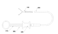
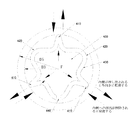
図1に示すように、端部操作機器が端部操作装置100、輸送装置200及び制御装置300を備える。
Example 1
As shown in FIG. 1, the end operating device includes an
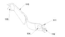
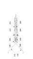
図2〜図16に示すように、端部操作装置100はクリップ、接続管120及び弾性部450を備え、クリップが接続管120に取り付けられ、接続管120に通路が設けられ、クリップの近位端は接続管120の遠位端から接続管120の通路を出入りすることができ、クリップは近位端が接続される2つの挟持片110を備え、挟持片110の遠位端に結紮歯113が設けられ、接続管120の遠位端に阻止部123が設けられ、阻止部123は2つの挟持片110の間に位置し、挟持片110又は接続ピン130を阻止することができ、挟持片110が接続管120の遠位端から脱出することを防止する。挟持片110の遠位端が接続管120の遠位端に接近すると、挟持片110が接続管120に押さえつけられて閉じることになる。
As shown in FIGS. 2 to 16, the
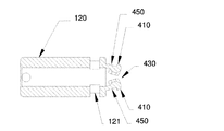
弾性部450は弾性リング400を備え、弾性リング400に外嵌孔430が設けられ、弾性リング400の外周面に制限凸部410が設けられ、弾性リング400が接続管120の通路内に設けられ、弾性リング400に外嵌孔430及び制限凸部410が設けられ、外嵌孔430が接続管120の通路に連通しており、接続管120の管壁に制限孔121が設けられ、制限孔121が制限凸部410に対応し、制限凸部410が制限孔121を通り抜け又は離れることができる。
The
輸送装置200はシース210及び心軸220を備え、シース210に通路が設けられ、心軸220がシース210の通路内に設けられ、心軸220の遠位端に接続先端230が設けられ、シース210がシース本体及びエンドカバー250を備え、エンドカバー250に制限段差270が設けられ、制限段差270がシース本体の遠位端端面とともに制限凹部240をなす。
The
制御装置300がハンドル310及び摺動部320を備え、ハンドル310がシース210に接続され、摺動部320が心軸220に接続され、摺動部320がハンドル310に対して摺動することができ、遠位端又は近位端へ摺動部320を摺動することにより、心軸220がシース210に対して遠位端又は近位端へ移動するように駆動することができる。
The
シース210が弾性リング400の外部に被装される場合、接続先端230が外嵌孔430に伸び込み又は外嵌孔430を離れることができ、接続先端230が外嵌孔430に伸び込まれる場合、弾性リング400が外向きに拡張し、制限凸部410が制限凹部240に伸び込まれ、接続管120をシース210に接続させ、接続先端230が外嵌孔430を離れる場合、弾性リング400が反発し、制限凸部410が制限凹部240を離れ、接続管120とシース210との接続関係を解除させる。
When the
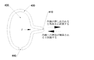
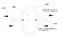
弾性リング400が外嵌孔430から与えた押出力を受ける(図10に示される力Fの方向)と、弾性リング400が外向きに(図10に示される実線矢印の方向)拡張し、弾性リング400の受けた外嵌孔430から与えた押出力が解除されると、弾性リング400が反発する(図10に示される点線矢印の方向)。弾性リング400に欠け口440が設けられる。欠け口440は弾性リング400が押し出されて拡張する幅を増加させ、制限凸部410と制限凹部240との接続を強化することができるとともに、接続先端230を外嵌孔430内に容易に被装させることもできる。弾性リング400の横断面の形状を制限せず、図11に示される(a)〜(h)のような形状を用いることが好ましい。
When the
本実施例では、制限凹部240がシース210の内壁における溝であり、シース210がシース本体及びシース本体の遠位端に設けられるエンドカバー250を備え、エンドカバー250に制限段差270が設けられ、エンドカバー250を設置することにより制限凹部240を製造すれば、製造プロセスが簡単になるが、これに限らず、シース210の側壁に止まり孔、貫通孔又は溝を開けることにより、制限凹部240をなし、又は、シース210の内壁にシース210の中心軸へ突起する段差を設置し、段差とシース210の内壁との間に制限凹部240をなすことにより、制限凸部410がシース210の遠位端から滑り出すのを制限してもよい。
In this embodiment, the limiting
本実施例では、図9、図10、図12に示すように、接続管120の近位端に位置決めリング150が設けられ、接続管120の内壁に段差が設けられ、段差及び位置決めリング150によって弾性リング400を接続管120の近位端に固定する。しかしながら、これに限らず、弾性リング400を接続管120の通路内に直接置くことにより弾性リング400の制限凸部410を制限孔121に伸び込ませ、又は接続管120内に弾性リング400を取り付ける位置決め構造を設置してもよい。
In this embodiment, as shown in FIGS. 9, 10 and 12, a
制限凸部410の側面に制限部420が設けられ、制限部420が接続管120の通路内に位置する。弾性リング400が押し出されて外向きに拡張する場合、制限部420が制限凹部240の外部に当接され、又は制限部420が制限孔121近傍に当接されることにより、弾性リング400が過度に開くことを防止することができる。
A limiting
挟持片110の近位端に後部挟持部112が設けられ、2つの後部挟持部112の間に隙間が設けられ、2つの後部挟持部112の間の隙間が係着孔115をなし、係着孔115が接続管120の通路に連通している。挟持片110自体が係着孔115をなすため、構造が簡単である。一般的に挟持片110が扁平なシート状であり、好ましくは、挟持片110の近位端を扁平面に垂直又は略垂直な方向に沿って曲げてLフックをなし、図16に示すように、2つの挟持片110のLフックの間の隙間が係着孔115をなし、2つの挟持片110のLフックが係着孔115に対して対称的に設置され、2つの挟持片110のLフックが係着孔115のエッジである。このような方式で扁平状の挟持片110に係着孔115を設置すれば、構造が簡単になり、生産効率が高くなる。
A
接続先端230の遠位端に係着部が設けられ、係着部が係着孔115に係合され、係着部が凹溝部232及び膨大部231を備え、凹溝部232が膨大部231と接続先端230との間に位置し、膨大部231の最大幅(図14に示されるD1)が凹溝部232の最小幅(図14に示されるD2)より大きく、膨大部231の最大幅が係着孔115の最小幅より大きい。
An engagement portion is provided at the distal end of the
クリップは更に接続ピン130を備え、挟持片110の近位端にロック凸部111及び接続孔114が設けられ、接続ピン130が接続孔114内に穿設され、2つの挟持片110が接続管120に押さえつけられて閉じると、2つの挟持片110の近位端が接続ピン130に沿って摺動して、離れる方向(例えば、図16における矢印で示す方向)へ弾けることになり、ロック凸部111がロック凹部122に伸び込まれる。
The clip is further provided with a connecting
挟持片110の近位端が接続管120の遠位端に接近すると、挟持片110の遠位端が離れることになり、この時、挟持片110が開かれており、挟持片110の近位端が接続管120の近位端に接近すると、挟持片110の遠位端が接続管120に押さえつけられて閉じて、挟持片110の近位端が離れる方向へ開くことになり、ロック凸部111がロック凹部122に伸び込まれ、これにより、挟持片110を接続管120にロックして、挟持片110が接続管120に対して移動しないようにして、挟持片110を閉じ状態に維持して、結紮後にクリップが開くことを防止する。好ましくは、挟持片110自体に弧度が設けられ、挟持片110の弧度によって挟持片110が自動的に開き又は閉じることができる。
When the proximal end of the holding
図4、図14に示すように、膨大部231の遠位端に案内部233が設けられ、案内部233の横断面が近位端から遠位端へ徐々に減少する。案内部233の横断面は案内部233の垂直又は略垂直な膨大部231において遠位端へ移動する方向における断面を指し、案内部233の横断面が徐々に減少することにより案内部233の外表面に案内斜面を形成させ、膨大部231が係着孔115にスムーズに伸び込むように案内することができる。
As shown in FIGS. 4 and 14, a
クリップが閉じた後、心軸220を近位端へ移動するように引き続けると、クリップが近位端へ移動するように駆動することになり、前記係着部が前記係着孔115を離れると、前記クリップと前記心軸220との接続が解除される。係着孔115のエッジが膨大部231に押し出されて変形、破壊又は破断する可能性があるが、この時、接続先端230とクリップとの分離が完了しているため、実際の使用に影響を与えることがない。
After the clip is closed, if the
好ましくは、適切な係着孔115の形状及び直径、膨大部231の形状及び幅、係着孔115周辺の材料を設計することにより、膨大部231と係着孔115を非破壊的に繰り返し係着又は接触係着させることができる。
Preferably, by designing an appropriate shape and diameter of the
本実施例では、端部操作装置100及び輸送装置200を繰り返し脱着でき、端部操作装置100が人体を結紮した後、端部操作装置100が輸送装置200を離れ、輸送装置200を再利用でき、端部操作装置100と輸送装置200を別々に製造して、端部操作装置100と輸送装置200を組み立てて使用してもよく、図17〜図23には端部操作装置100と輸送装置200を組み立てる方法を示し、本実施例では組み立てケース500を利用して組み立てることにより、組み立て効率を向上させ、操作を容易にし、組み立て効率を向上させることができるだけでなく、医療スタッフの使用にも役立つ。
In this embodiment, the
図17に示すように、組み立てケース500がケース本体を備え、ケース本体が接続される収納部分510及び締め付け部分520を備え、収納部分510に端部操作装置収納室が設けられ、端部操作装置収納室がクリップ収納室511及びクリップ収納室511に連通している接続管収納室を含み、クリップ収納室511がクリップを収納することに用いられ、接続管収納室が接続管120を収納することに用いられる。
As shown in FIG. 17, the
クリップ収納室511が広がり状態にあるクリップを収納する。
The
クリップ収納室511と接続管収納室との間に位置決め凸部513が設けられ、位置決め凸部513が接続管120の遠位端に当接されることに用いられる。
A positioning
締め付け部分520にシース収納室が設けられ、シース収納室がシース210を収納することに用いられ、シース収納室の一端が端部操作装置収納室に連通しており、他端に開口部が設けられる。
Clamping
締め付け部分520が押出力(例えば、図19における矢印方向)を受けると、シース収納室の最小幅が小さくなる。
When the tightening
図19に示すように、締め付け部分520が少なくとも2つの挟持弁522を備え、少なくとも2つの挟持弁522の間がシース収納室に囲まれ、挟持弁522が押出力を受けると、少なくとも2つの挟持弁522が接近する方向へ集まることになり、シース収納室の最小幅が小さくなる。
As shown in FIG. 19, when the tightening
組み立てる時、
(1)図18、図19に示すように、端部操作装置100を端部操作装置収納室内に置き、クリップを広がり状態でクリップ収納室511内に収納し、接続管120を接続管収納室に収納し、接続管120の遠位端を位置決め凸部513に当接させる。
(2)シース210をシース収納室の近位端の開口部から挿入し、シース210を接続管120の近位端の外部に被装させ、この時、シース210を弾性リング400の外部に被装し、図20に示すように、締め付け部の挟持弁522(例えば、図20における矢印に示される)を押し出して、後続操作のために、挟持弁522にシース210の位置を固定させる。
(3)図21に示すように、摺動部320を押動して心軸220が遠位端へ移動するように駆動し、接続先端230を外嵌孔430に伸び込ませ、押し出して図21に示される矢印方向に沿って外向きに拡張するように制限し、制限凸部410が制限孔121を通り抜けて制限凹部240に伸び込まれるようにし、シース210を接続管120に接続させ、次に心軸220を遠位端へ移動させ、係着部の膨大部231が係着孔115を通り抜けるようにし、係着孔115のエッジが凹溝部232に引っかかって、心軸220をクリップに接続させ、この時、心軸220を移動すると、クリップが遠位端又は近位端へ移動するように駆動することができる。
(4)図21に示すように、心軸220が近位端へ移動するように引くことにより、クリップが近位端へ移動するように駆動し、クリップを徐々に接続管120内に収め、クリップを閉じ、この時、挟持片110はクリップがクリップ収納室511から脱出することを阻止せず、次に、端部操作装置100、輸送装置200が組み立てケース500のシース収納室の近位端の開口部から脱出するまで、近位端へ心軸220を引き続け、
ここまでで、組み立てが完了する。
When assembling
(1) As shown in FIGS. 18 and 19, placing the
(2) The
(3) As shown in FIG. 21, the sliding
(4) As shown in FIG. 21, by pulling the
At this point, assembly is complete.
クリップ収納室511が開放してもよいし、開放しなくてもよく、殺菌の観点から考慮すれば、出荷時に端部操作装置100がクリップ収納室511内に密封されることが好ましい。
The
実施例2
実施例2と実施例1との相違点は以下のとおりである。
Example 2
The differences between Example 2 and Example 1 are as follows.
図24〜図26に示すように、弾性リング400と接続管120とが一体であり、接続管120が管状であり、接続管120の近位端の管壁に弾性リング400を製造し、接続管120の通路が外嵌孔430であり、接続先端230が外嵌孔430に伸び込まれる場合、弾性リング400における制限凸部410が外向きに押し出されてシース210の制限凹部240に伸び込まれ、シース210を接続管120に接続させ、接続先端230が外嵌孔430を離れる場合、弾性リング400が弾性アームの作用を果たし、自動的に反発し、制限凸部410を制限凹部240から離れさせ、接続端とシース210との接続関係が解除される。
As shown in FIGS. 24 to 26, the
本実施例では、端部操作装置100と輸送装置200との組み立ては実施例1と同様であり、実施例1の組み立てケース500を用いてもよい。
In this embodiment, the assembly of the
実施例3
実施例3と実施例1との相違点は以下のとおりである。
Example 3
The differences between Example 3 and Example 1 are as follows.
弾性リング400及び制限凹部240の位置が変化し、図27〜図29に示すように、シース210に弾性リング400が設けられるが、接続管120に制限凹部240が設けられる。
The positions of the
本実施例では、接続管120の内壁に制限凹部240が設けられる。
In this embodiment, the limiting
シース210の遠位端に弾性リング400が設けられ、弾性リング400がシース210の通路内に設けられ、弾性リング400が弾性リング400であり、弾性リング400に外嵌孔430及び制限凸部410が設けられ、シース210の管壁に制限孔121が設けられ、制限孔121が制限凸部410に対応する。
An
弾性リング400が接続管120の通路に伸び込まれる場合、接続先端230が外嵌孔430に伸び込み又は外嵌孔430を離れることができ、接続先端230が外嵌孔430に伸び込まれる場合、弾性リング400を押し出して外向きに拡張させ、制限凸部410が制限凹部240に伸び込まれ、接続先端230が外嵌孔430を離れる場合、弾性リング400が反発し、制限凸部410が制限凹部240を離れる。
When the
本実施例では、端部操作装置100と輸送装置200との組み立ては実施例1と同様であり、実施例1の組み立てケース500を用いてもよい。
In this embodiment, the assembly of the
実施例4
実施例4と実施例1との相違点は以下のとおりである。
Example 4
The differences between Example 4 and Example 1 are as follows.
弾性リング400の構造が変化し、本実施例では、弾性リング400の構造が変化し、本実施例では、図30、図31に示すように、欠け口440が設けられる1つの弾性リング400において3つの制限凸部410が中心対称的に設けられ、2つの隣接する制限凸部410の間の突起が制限部420であり、受け力を均一にするために、対称的にし、弾性リング400の環状そのものに制限凸部410が突起するだけでなく、制限部420も突起し、構造が簡単である。
The structure of the
接続先端が外嵌孔内に被装されていない場合、3つの制限凸部410からなる全体の直径D3が制限凹部のエッジのシースにおける直径D5より小さく、D3<D5であり、シースが接続管に対して自在に摺動し、接続先端が外嵌孔内に被装されていない場合、3つの制限凸部410からなる全体の直径がD3からD4に外向きに拡張し、D4>D5であり、制限凸部が制限凹部に伸び込まれ、それにより接続管に対するシースの摺動を制限する。
When the connection tip is not covered in the outer fitting hole, the total diameter D3 consisting of the three limiting
実施例5
実施例5と実施例1との相違点は以下のとおりである。
Example 5
The differences between Example 5 and Example 1 are as follows.
弾性リング400の構造が変化し、本実施例では、図32に示すように、制限輪が楕円形であり、制限凸部410が楕円形の短軸に沿って外向きに突起し、接続先端230が制限孔121に挿入される場合、図32に示される力Fの方向に沿って、楕円形の短軸方向から外へ弾性リング400を押し出し、制限凸部410を外向きに拡張させる。制限凸部410が外向きに拡張−反発する際に、より長いストロークを有してもよい。
The structure of the
図32、図33に示すように、1つの制限凸部410を設置してもよいし、図33、図34に示すように、2つの制限凸部410を設置してもよい。
As shown in FIGS . 32 and 33 , one limiting
図33、図35に示すように、弾性リング400に欠け口440を設置してもよいし、図32、図34に示すように、閉じた輪であってもよい。
As shown in FIGS . 33 and 35 , the
実施例6
実施例6と実施例1との相違点は以下のとおりである。
Example 6
The differences between Example 6 and Example 1 are as follows.
弾性リング400の構造が変化し、本実施例では、図36に示すように、弾性リング400及び制限凸部410が同じ平面に位置せず、1つ又は2つ以上の制限凸部410が弾性リング400の同じ側に設けられる。
The structure of the
実施例7
実施例7と実施例1との相違点は以下のとおりである。
Example 7
The differences between Example 7 and Example 1 are as follows.
弾性リング400の構造が変化し、本実施例では、図37に示すように、弾性リング400の一方側に2つ又は3つ以上のJフックが設けられ、Jフックの一端が弾性リング400に接続され、他端が自由端であり、自由端が制限凸部410であり、接続先端230が外嵌孔430に挿入される場合、接続先端230が弾性リング400及びJフックを同時に押し出して、制限凸部410を外向きに拡張させ、接続先端230を外嵌孔430から取り出した後、弾性リング400及びJフックが反発して、制限凸部410を内向きに反発させる。弾性リング400が円形リングであってもよいし、楕円形リングであってもよい。
The structure of the
実施例8
実施例8と実施例1との相違点は以下のとおりである。
Example 8
The differences between Example 8 and Example 1 are as follows.
図38、図39に示すように、Jフックが内向きに凹んでおり、2つのJフックの間の隙間が外嵌孔430をなし、接続先端230が外嵌孔430に挿入される場合、接続先端230が弾性リング400を通り抜けるがそれを押し出さず、接続先端230がJフックを押し出して、制限凸部410を外向きに拡張させ、接続先端230を外嵌孔430から取り出した後、Jフックが反発して、制限凸部410を内向きに反発させる。
As shown in FIGS . 38 and 39 , when the J hook is recessed inward, the gap between the two J hooks forms an outer
実施例9
実施例9と実施例1との相違点は以下のとおりである。
Example 9
The differences between Example 9 and Example 1 are as follows.
図40に示すように、弾性リング400が少なくとも2つのハーフリング460からなり、少なくとも2つのハーフリング460が外嵌孔430に囲まれ、ハーフリング460に制限凸部410が設けられる。
As shown in FIG. 40 , the
ハーフリング460が接続管120の通路内に直接被装されることにより、制限凸部410を制限孔121に位置合わせさせてもよい。ハーフリング460が1/2輪、1/3輪又は他の形状の輪であってもよく、接続ポートで外嵌孔430から取り出す際に自動的に反発して、端部操作装置100とシース210との接続を解除させればよい。
The limiting
実施例10
実施例10と実施例9との相違点は以下のとおりである。
Example 10
The differences between Example 10 and Example 9 are as follows.
弾性部が1つのハーフリングを備え、ハーフリングが図40における左側又は右側のハーフリングを参照してもよく、ハーフリングが接続管の通路内に設けられ、ハーフリングの一方側に制限凸部が設けられ、ハーフリングの他方側と接続管の内壁との間が外嵌孔をなす。 The elastic portion comprises one halfling, the halfling may refer to the left or right halfling in FIG. 40, the halfling is provided in the passage of the connecting tube and the limiting convex portion on one side of the halfling. Is provided, and an outer fitting hole is formed between the other side of the halfling and the inner wall of the connecting pipe.
実施例11
実施例11と実施例1との相違点は以下のとおりである。
Example 11
The differences between Example 11 and Example 1 are as follows.
図41、図42に示すように、シース210に弾性部450が設けられ、弾性部450とシース210とが一体であり(本実施例に限らず、分離式であってもよい)、接続管120の外壁に制限凹部240が設けられ、弾性部450の内壁に制限凸部410が設けられる。
As shown in FIGS. 41 and 42, the
弾性部450に外嵌孔430が設けられ、外嵌孔430がシース210の通路に連通しており、接続先端230を遠位端へ移動させ、接続先端230が外嵌孔430に伸び込まれる場合、弾性部450の制限凸部410が外向きに押し出されて開かれ、接続管120及び制限凸部410が外嵌孔430を通り抜けることができ、接続管120の近位端を接続孔に伸び込ませ、次に接続先端230が遠位端へ移動し、接続先端230が外嵌孔430を通り抜けた後、弾性部450の受けた接続先端230が外嵌孔430から与えた外向きの押出力がなくなり、弾性部450が反発し、制限凸部410が制限凹部240に伸び込まれ、制限凸部410が制限凹部240にフィットされることにより接続管120をシース210に接続させ、この時、輸送装置200を操作すると、端部操作装置が移動するように駆動することができる。接続管120とシース210との接続関係を解除する必要がある場合、接続先端230を近位端へ移動させ、接続先端230が外嵌孔430に伸び込まれる場合、接続先端230が外嵌孔430の内壁から弾性部450へ外向きの押出力を与え、弾性部450が拡張され、接続管120及び制限凸部410が外嵌孔430を通り抜けることができ、この時、接続管120の近位端とシース210の遠位端とを分離すると、接続管120とシース210との接続関係が解除され、次に接続先端230が近位端へ移動し続け、接続先端230が外嵌孔430から離れ、弾性部450が反発し、シース210及び弾性部450が次回の接続管120との接続に用意される。
An outer
本実施例では、接続管120に制限凹部240及び制限凸部410が同時に設けられ、弾性部450に制限凹部240及び制限凸部410が同時に設けられ、制限凹部240と制限凸部410とが係止して接続を完了する。しかしながら、これに限らず、接続管120に制限凹部240が設けられ、弾性部450に制限凸部410が設けられ、又は、接続管120に制限凸部410が設けられ、弾性部450に制限凹部240が設けられてもよい。
In this embodiment, the connecting
実施例12
実施例12と実施例5との相違点は以下のとおりである。
Example 12
The differences between Example 12 and Example 5 are as follows.
図43に示すように、弾性リング400と制限凸部410とが分離式である。制限凸部410が係止、溶接、接着又は他の接続方式で弾性リング400に取り付けられる。
As shown in FIG. 43, the
以上の実施例の各技術的特徴を任意に組み合わせてもよく、説明を簡潔にするために、上記実施例の各技術的特徴のすべての可能な組み合わせを説明しないが、矛盾しない限り、これらの技術的特徴の組み合わせは、いずれも本明細書に記載の範囲に含まれると見なされるべきである。 The technical features of the above examples may be arbitrarily combined, and for the sake of brevity, all possible combinations of the technical features of the above examples will not be described, but unless contradictory, these Any combination of technical features should be considered to be within the scope described herein.
以上の実施例は本発明のいくつかの実施形態を説明するためのものであり、その説明がより具体的且つ詳細であるが、本発明の範囲を制限するためのものではない。説明すべきことは、当業者であれば、本発明の構想を逸脱せずに、更に種々の変形や改良を行うことができ、これらの変形や改良はいずれも本発明の保護範囲に属する。従って、本発明の保護範囲は特許請求の範囲に準じるべきである。 The above examples are for explaining some embodiments of the present invention, and although the description is more specific and detailed, they are not for limiting the scope of the present invention. It should be explained that a person skilled in the art can make various modifications and improvements without departing from the concept of the present invention, and all of these modifications and improvements belong to the scope of protection of the present invention. Therefore, the scope of protection of the present invention should conform to the scope of claims.
100 端部操作装置
110 挟持片
111 ロック凸部
112 後部挟持部
113 結紮歯
114 接続孔
115 係着孔
120 接続管
121 制限孔
122 ロック凹部
123 阻止部
130 接続ピン
140 位置決め溝
150 位置決めリング
200 輸送装置
210 シース
220 心軸
230 接続先端
231 膨大部
232 凹溝部
233 案内部
240 制限凹部
250 エンドカバー
270 制限段差
300 制御装置
310 ハンドル
320 摺動部
400 弾性リング
410 制限凸部
420 制限部
430 外嵌孔
440 欠け口
450 弾性部
460 ハーフリング
500 組み立てケース
510 収納部分
511 クリップ収納室
512 接続管収納室
513 位置決め凸部
520 締め付け部分
521 シース収納室
522 挟持弁
100
Claims (20)
クリップ、弾性部及び接続管を備え、前記弾性部に外嵌孔が設けられ、前記弾性部に制限凸部が設けられ、前記クリップが前記接続管に取り付けられ、前記接続管に通路が設けられる端部操作装置と、
シース及び心軸を備え、前記シースに通路が設けられ、前記心軸が前記シースの通路内に設けられ、前記心軸の遠位端に接続先端が設けられ、前記シースに制限凹部が設けられる輸送装置と、を備え、
前記シースが前記弾性部の外部に被装される場合、前記接続先端が前記外嵌孔に伸び込み又は前記外嵌孔を離れることができ、前記接続先端が前記外嵌孔に伸び込まれる場合、前記弾性部が外向きに拡張し、前記制限凸部が前記制限凹部に伸び込まれ、前記接続先端が前記外嵌孔を離れる場合、前記弾性部が反発し、前記制限凸部が前記制限凹部を離れることを特徴とする端部操作機器。 It is an end operation device
A clip, an elastic portion and a connecting pipe are provided, an outer fitting hole is provided in the elastic portion, a limiting convex portion is provided in the elastic portion, the clip is attached to the connecting pipe, and a passage is provided in the connecting pipe. With the end control device,
The sheath is provided with a sheath and a core shaft, the sheath is provided with a passage, the core shaft is provided in the passage of the sheath, a connection tip is provided at the distal end of the core shaft, and the sheath is provided with a limiting recess. Equipped with a transport device,
When the sheath is placed on the outside of the elastic portion, the connection tip can extend into or leave the outer fitting hole, and the connecting tip extends into the outer fitting hole. When the elastic portion expands outward, the limiting convex portion extends into the limiting concave portion, and the connection tip leaves the outer fitting hole, the elastic portion repels and the limiting convex portion becomes the limiting concave portion. An end-manipulating device characterized by leaving a recess.
接続管及び前記接続管に取り付けられるクリップを備え、前記接続管に通路が設けられ、前記接続管の内壁に制限凹部が設けられる端部操作装置と、
シース及び心軸を備え、前記シースに通路が設けられ、前記心軸が前記シースの通路内に設けられ、前記心軸の遠位端に接続先端が設けられ、前記シースの遠位端に弾性部が設けられ、前記弾性部に外嵌孔が設けられ、前記外嵌孔が前記シースの通路に連通しており、前記弾性部に制限凸部が設けられる輸送装置と、を備え、
前記弾性部が前記接続管の通路に伸び込まれる場合、前記接続先端が前記外嵌孔に伸び込み又は前記外嵌孔を離れることができ、前記接続先端が前記外嵌孔に伸び込まれる場合、前記弾性部を押し出して外向きに拡張させ、前記制限凸部が前記制限凹部に伸び込まれ、前記接続先端が前記外嵌孔を離れる場合、前記弾性部が反発し、前記制限凸部が前記制限凹部を離れることを特徴とする端部操作機器。 It is an end operation device
An end operating device including a connecting pipe and a clip attached to the connecting pipe, the connecting pipe is provided with a passage, and the inner wall of the connecting pipe is provided with a limiting recess.
A sheath and a core are provided, the sheath is provided with a passage, the core is provided in the passage of the sheath, a connecting tip is provided at the distal end of the core, and the distal end of the sheath is elastic. A transport device is provided, the elastic portion is provided with an outer fitting hole, the outer fitting hole communicates with the passage of the sheath, and the elastic portion is provided with a limiting convex portion.
When the elastic portion extends into the passage of the connecting pipe, the connecting tip can extend into or leave the outer fitting hole, and the connecting tip extends into the outer fitting hole. When the elastic portion is pushed out and expanded outward, the limiting convex portion is extended into the limiting concave portion, and the connection tip leaves the outer fitting hole, the elastic portion repels and the limiting convex portion is formed. An end operating device characterized by leaving the limiting recess.
前記弾性部が前記外嵌孔の内側から与えた押出力を受けると、前記弾性部が外向きに拡張し、前記弾性部の受けた前記外嵌孔から与えた押出力が解除されると、前記弾性部が反発することを特徴とする端部操作装置。 A clip, an elastic portion docked to the clip, and a connecting pipe are provided, an outer fitting hole is provided in the elastic portion, a limiting convex portion is provided in the elastic portion, and the clip is attached to the connecting pipe. , The connecting pipe is provided with a passage,
When the elastic portion receives the push output given from the inside of the outer fitting hole, the elastic portion expands outward, and when the push output given from the outer fitting hole received by the elastic portion is released, An end operation device characterized in that the elastic portion repels.
前記接続先端が前記外嵌孔に伸び込み又は前記外嵌孔を離れることができ、前記接続先端が前記外嵌孔に伸び込まれる場合、前記弾性部が外向きに拡張し、前記接続先端が前記外嵌孔を離れる場合、前記弾性部が反発することを特徴とする輸送装置。 A sheath and a core are provided, the sheath is provided with a passage, the core is provided in the passage of the sheath, a connecting tip is provided at the distal end of the core, and the distal end of the sheath is elastic. A portion is provided, an outer fitting hole is provided in the elastic portion, the outer fitting hole communicates with the passage of the sheath, and a limiting convex portion is provided in the elastic portion.
When the connecting tip can extend into or leave the outer fitting hole and the connecting tip extends into the outer fitting hole, the elastic portion expands outward and the connecting tip expands outward. A transport device characterized in that the elastic portion repels when leaving the outer fitting hole.
Applications Claiming Priority (1)
| Application Number | Priority Date | Filing Date | Title |
|---|---|---|---|
| PCT/CN2017/083092 WO2018201406A1 (en) | 2017-05-04 | 2017-05-04 | End portion execution instrument, end portion execution device, delivery device, and assembly box |
Publications (2)
| Publication Number | Publication Date |
|---|---|
| JP2020518390A JP2020518390A (en) | 2020-06-25 |
| JP6875552B2 true JP6875552B2 (en) | 2021-05-26 |
Family
ID=64016870
Family Applications (1)
| Application Number | Title | Priority Date | Filing Date |
|---|---|---|---|
| JP2019560289A Active JP6875552B2 (en) | 2017-05-04 | 2017-05-04 | End control device, end control device, transportation device and assembly case |
Country Status (6)
| Country | Link |
|---|---|
| US (1) | US11259815B2 (en) |
| EP (1) | EP3603536A4 (en) |
| JP (1) | JP6875552B2 (en) |
| CN (4) | CN116942242A (en) |
| AU (1) | AU2017412462B2 (en) |
| WO (1) | WO2018201406A1 (en) |
Families Citing this family (17)
| Publication number | Priority date | Publication date | Assignee | Title |
|---|---|---|---|---|
| CN116942242A (en) * | 2017-05-04 | 2023-10-27 | 杭州安杰思医学科技股份有限公司 | End effector and conveying device |
| WO2018227592A1 (en) * | 2017-06-16 | 2018-12-20 | 杭州安杰思医学科技有限公司 | Ligation device, unlocking method and ligation instrument |
| WO2019089464A1 (en) * | 2017-10-30 | 2019-05-09 | Threlkeld Judson E | Catheter removal instruments and methods |
| CN113194849B (en) * | 2018-12-11 | 2024-07-19 | 奥林巴斯株式会社 | Cassette, fixture system and fixture installation method |
| WO2020136826A1 (en) * | 2018-12-27 | 2020-07-02 | オリンパス株式会社 | Medical device and method of installing medical device |
| EP3725244A1 (en) * | 2019-04-17 | 2020-10-21 | Micro-Tech (Nanjing) Co., Ltd. | Medical device for causing the hemostasis of a blood vessel |
| CN119405360A (en) * | 2019-05-28 | 2025-02-11 | 波士顿科学国际有限公司 | Hemostatic Clip Deployment Device |
| CN112137672B (en) * | 2019-06-28 | 2024-11-29 | 南微医学科技股份有限公司 | Tissue clamping device for passing through endoscope |
| CN110292411B (en) * | 2019-08-06 | 2024-04-16 | 南微医学科技股份有限公司 | Tissue clamping device |
| CN110638487A (en) * | 2019-10-25 | 2020-01-03 | 安瑞医疗器械(杭州)有限公司 | A rotatable spatula used under endoscope |
| CN110613495B (en) * | 2019-10-29 | 2025-09-16 | 南微医学科技股份有限公司 | Medical hemostatic clamp |
| EP4046579B1 (en) * | 2019-11-13 | 2024-09-18 | Hangzhou AGS MedTech Co., Ltd. | End effector device |
| US12446878B2 (en) | 2019-11-14 | 2025-10-21 | Hangzhou Ags Medtech Co., Ltd. | Multi-processing device for an endoscope and use method thereof |
| CN111658058B (en) * | 2020-06-29 | 2022-09-13 | 安瑞医疗器械(杭州)有限公司 | Clip device for use with endoscope and clip portion thereof |
| CN113967048A (en) * | 2020-07-24 | 2022-01-25 | 拓普微创医疗科技常州有限公司 | Bundling piece |
| US12426882B2 (en) | 2022-03-01 | 2025-09-30 | Olympus Medical Systems Corp. | Clip unit, clip delivery device, and loading method of clip unit |
| WO2024188193A1 (en) * | 2023-03-10 | 2024-09-19 | 江苏唯德康医疗科技有限公司 | Hemostatic clip assembly and hemostatic clip comprising same |
Family Cites Families (41)
| Publication number | Priority date | Publication date | Assignee | Title |
|---|---|---|---|---|
| US5797939A (en) * | 1989-12-05 | 1998-08-25 | Yoon; Inbae | Endoscopic scissors with longitudinal operating channel |
| US6911032B2 (en) | 1999-11-18 | 2005-06-28 | Scimed Life Systems, Inc. | Apparatus and method for compressing body tissue |
| US7094245B2 (en) | 2001-10-05 | 2006-08-22 | Scimed Life Systems, Inc. | Device and method for through the scope endoscopic hemostatic clipping |
| US7727247B2 (en) * | 2002-08-21 | 2010-06-01 | Olympus Corporation | Living tissue ligation device |
| JP4242614B2 (en) * | 2002-08-21 | 2009-03-25 | オリンパス株式会社 | Biological tissue ligation device |
| EP3878381A3 (en) | 2003-09-30 | 2021-11-10 | Boston Scientific Scimed, Inc. | Through the scope tension member release clip |
| JP4273040B2 (en) * | 2004-05-24 | 2009-06-03 | Hoya株式会社 | Endoscopic clip device |
| EP1818020B1 (en) | 2004-12-07 | 2017-05-10 | Olympus Corporation | Endo-therapy product system and cartridge including a treatment device |
| JP4758173B2 (en) * | 2004-12-24 | 2011-08-24 | オリンパス株式会社 | Ligation device |
| US8157837B2 (en) | 2006-03-13 | 2012-04-17 | Pneumrx, Inc. | Minimally invasive lung volume reduction device and method |
| EP2020925B1 (en) * | 2006-06-01 | 2013-07-10 | Cook Medical Technologies LLC | Release mechanisms for a clip device |
| US8162959B2 (en) * | 2007-05-03 | 2012-04-24 | Boston Scientific Scimed, Inc. | Single stage hemostasis clipping device |
| JP5246394B2 (en) * | 2007-11-28 | 2013-07-24 | 住友ベークライト株式会社 | Clip, clip unit and clip device |
| US20110054498A1 (en) * | 2008-05-05 | 2011-03-03 | Niti Surgical Solutions Ltd. | Endoscopic compression clip and system and method for use thereof |
| US9173669B2 (en) | 2008-09-12 | 2015-11-03 | Pneumrx, Inc. | Enhanced efficacy lung volume reduction devices, methods, and systems |
| WO2011022246A1 (en) | 2009-08-19 | 2011-02-24 | Boston Scientific Scimed, Inc. | Multifunctional core for two-piece hemostasis clip |
| JP5588711B2 (en) * | 2010-03-30 | 2014-09-10 | 富士フイルム株式会社 | Ligation device |
| EP2615987B1 (en) | 2010-09-14 | 2014-05-14 | Boston Scientific Scimed, Inc. | Release mechanism for hemostasis clip |
| JP5343113B2 (en) * | 2011-09-15 | 2013-11-13 | 富士フイルム株式会社 | Clip unit and ligating apparatus using the same |
| WO2013067662A1 (en) | 2011-11-11 | 2013-05-16 | Zhu Jian | Clamping or ligating device |
| US9138234B2 (en) * | 2011-11-14 | 2015-09-22 | Anrei Medical (Hz) Co., Ltd. | Clip apparatus for ligature of living tissue |
| CN202477780U (en) * | 2012-01-20 | 2012-10-10 | 东南大学 | Clamp control unit and clamp unit matched with clamp control unit in use |
| CN102525593B (en) * | 2012-01-20 | 2015-02-25 | 东南大学 | Clamp control unit and clamp unit matched with same |
| WO2013169873A1 (en) | 2012-05-09 | 2013-11-14 | Boston Scientific Scimed, Inc. | Bushing arm deformation mechanism |
| CN202699217U (en) | 2012-05-28 | 2013-01-30 | 杭州安杰思医学科技有限公司 | Hemostasis clamp capable of being repeatedly opened and closed and provided with pusher |
| CN202699219U (en) * | 2012-07-05 | 2013-01-30 | 安瑞医疗器械(杭州)有限公司 | Tissue hemostasis clamping device |
| JP2015532859A (en) * | 2012-09-24 | 2015-11-16 | ボストン サイエンティフィック サイムド,インコーポレイテッドBoston Scientific Scimed,Inc. | Solution mechanism for hemostatic clips |
| US10524786B2 (en) * | 2013-05-14 | 2020-01-07 | Mubashir H. Khan | Spring-closing endoscopic clip where the spring action can also reverse the clip prior anytime before full ejection |
| CN103315792B (en) | 2013-06-29 | 2015-06-03 | 安瑞医疗器械(杭州)有限公司 | Clamping device and jaw part thereof |
| CN203506934U (en) * | 2013-09-04 | 2014-04-02 | 杭州启明医疗器械有限公司 | Sheath core for conveying interventional instrument and conveying system with same |
| WO2016063679A1 (en) | 2014-10-24 | 2016-04-28 | 株式会社カネカ | Clip device for endoscope and method for mounting clip for implanting in body |
| US10646228B2 (en) | 2015-03-31 | 2020-05-12 | Sumitomo Bakelite Co., Ltd. | Endoscopic clip device and clip |
| US10335159B2 (en) | 2015-07-20 | 2019-07-02 | Boston Scientific Scimed, Inc. | Reloadable mechanical device for ligating living tissue and achieving hemostasis |
| WO2017066987A1 (en) | 2015-10-23 | 2017-04-27 | 杭州安杰思医学科技有限公司 | Ligation device |
| JP6274233B2 (en) | 2016-02-23 | 2018-02-07 | 住友ベークライト株式会社 | Clip cartridge system |
| US11020125B2 (en) | 2016-08-22 | 2021-06-01 | Boston Scientific Limited | Hemostasis reloadable clipping device with sleeve engagement |
| CN106419992B (en) * | 2016-10-28 | 2023-10-24 | 上海威尔逊光电仪器有限公司 | Clamping device and operation method thereof |
| EP4344656A3 (en) | 2016-11-22 | 2024-06-05 | Boston Scientific Medical Device Limited | Hemostasis reloadable clip release mechanism |
| WO2018106710A1 (en) | 2016-12-06 | 2018-06-14 | Boston Scientific Scimed, Inc. | Compressive coupler for reloadable hemostasis clipping device |
| CN116942242A (en) * | 2017-05-04 | 2023-10-27 | 杭州安杰思医学科技股份有限公司 | End effector and conveying device |
| WO2018227592A1 (en) * | 2017-06-16 | 2018-12-20 | 杭州安杰思医学科技有限公司 | Ligation device, unlocking method and ligation instrument |
-
2017
- 2017-05-04 CN CN202310922493.3A patent/CN116942242A/en active Pending
- 2017-05-04 EP EP17908447.0A patent/EP3603536A4/en active Pending
- 2017-05-04 US US16/609,794 patent/US11259815B2/en active Active
- 2017-05-04 CN CN201780090351.8A patent/CN110799130B/en active Active
- 2017-05-04 JP JP2019560289A patent/JP6875552B2/en active Active
- 2017-05-04 AU AU2017412462A patent/AU2017412462B2/en active Active
- 2017-05-04 WO PCT/CN2017/083092 patent/WO2018201406A1/en not_active Ceased
-
2018
- 2018-02-11 CN CN201810140418.0A patent/CN108784773B/en active Active
- 2018-02-11 CN CN202010258929.XA patent/CN111419327B/en active Active
Also Published As
| Publication number | Publication date |
|---|---|
| US11259815B2 (en) | 2022-03-01 |
| CN111419327A (en) | 2020-07-17 |
| EP3603536A4 (en) | 2020-07-29 |
| CN108784773B (en) | 2020-05-22 |
| CN111419327B (en) | 2022-03-18 |
| AU2017412462A1 (en) | 2019-11-21 |
| CN110799130B (en) | 2023-09-15 |
| US20200060685A1 (en) | 2020-02-27 |
| JP2020518390A (en) | 2020-06-25 |
| CN108784773A (en) | 2018-11-13 |
| CN116942242A (en) | 2023-10-27 |
| AU2017412462B2 (en) | 2021-03-25 |
| EP3603536A1 (en) | 2020-02-05 |
| WO2018201406A1 (en) | 2018-11-08 |
| CN110799130A (en) | 2020-02-14 |
Similar Documents
| Publication | Publication Date | Title |
|---|---|---|
| JP6875552B2 (en) | End control device, end control device, transportation device and assembly case | |
| US12076023B2 (en) | Hemostatic clipping devices and methods | |
| ES2881527T3 (en) | Spring Release Surgical Staple | |
| CN109640841B (en) | Hemostatic reloadable gripping device with cannula engagement | |
| US11350947B2 (en) | Ligation device, unlocking method and ligation instrument | |
| EP1882451B1 (en) | Clip apparatus for ligaturing living tissue | |
| US9545258B2 (en) | Tissue aperture securing and sealing apparatuses and related methods of use | |
| EP2327364B1 (en) | Ligation apparatus | |
| EP3298971B1 (en) | Clip device | |
| US20020177861A1 (en) | Clip device of endoscope | |
| JP2019524281A (en) | Surgical ligation clip | |
| CN102727276A (en) | Tissue hemostasis clamping device | |
| CN112137672A (en) | Tissue clamping device for endoscopic use | |
| CN208355513U (en) | Apparatus for ligating and ligation apparatus | |
| CN107072668A (en) | Soft tissue is pressed from both sides | |
| CN107847684B (en) | Dialysis needle | |
| WO2021083297A1 (en) | Intervention instrument release control mechanism, release method, and intervention instrument delivery system | |
| CN114901158A (en) | Multiple treatment device for endoscope and method of using the same | |
| JPH024384A (en) | Clamp | |
| US10426243B2 (en) | Hair fastener | |
| JP2000287981A (en) | Indwelling clip in cavity in living body | |
| KR20200085011A (en) | Clipping device for endoscope | |
| CN215960105U (en) | Medical titanium clip for purse suture | |
| CN215458350U (en) | A hepatic portal blocker | |
| CN223695940U (en) | A type of hepatic hilum block band |
Legal Events
| Date | Code | Title | Description |
|---|---|---|---|
| A521 | Request for written amendment filed |
Free format text: JAPANESE INTERMEDIATE CODE: A523 Effective date: 20191101 |
|
| A621 | Written request for application examination |
Free format text: JAPANESE INTERMEDIATE CODE: A621 Effective date: 20191101 |
|
| A977 | Report on retrieval |
Free format text: JAPANESE INTERMEDIATE CODE: A971007 Effective date: 20201020 |
|
| A131 | Notification of reasons for refusal |
Free format text: JAPANESE INTERMEDIATE CODE: A131 Effective date: 20201027 |
|
| A601 | Written request for extension of time |
Free format text: JAPANESE INTERMEDIATE CODE: A601 Effective date: 20210115 |
|
| A521 | Request for written amendment filed |
Free format text: JAPANESE INTERMEDIATE CODE: A523 Effective date: 20210305 |
|
| TRDD | Decision of grant or rejection written | ||
| A01 | Written decision to grant a patent or to grant a registration (utility model) |
Free format text: JAPANESE INTERMEDIATE CODE: A01 Effective date: 20210406 |
|
| A61 | First payment of annual fees (during grant procedure) |
Free format text: JAPANESE INTERMEDIATE CODE: A61 Effective date: 20210422 |
|
| R150 | Certificate of patent or registration of utility model |
Ref document number: 6875552 Country of ref document: JP Free format text: JAPANESE INTERMEDIATE CODE Ref document number: 6875552 Country of ref document: JP Free format text: JAPANESE INTERMEDIATE CODE: R150 |
|
| R250 | Receipt of annual fees |
Free format text: JAPANESE INTERMEDIATE CODE: R250 |
|
| R250 | Receipt of annual fees |
Free format text: JAPANESE INTERMEDIATE CODE: R250 |
|
| R250 | Receipt of annual fees |
Free format text: JAPANESE INTERMEDIATE CODE: R250 |