JP6873619B2 - Image forming device - Google Patents
Image forming device Download PDFInfo
- Publication number
- JP6873619B2 JP6873619B2 JP2016133440A JP2016133440A JP6873619B2 JP 6873619 B2 JP6873619 B2 JP 6873619B2 JP 2016133440 A JP2016133440 A JP 2016133440A JP 2016133440 A JP2016133440 A JP 2016133440A JP 6873619 B2 JP6873619 B2 JP 6873619B2
- Authority
- JP
- Japan
- Prior art keywords
- remaining amount
- toner
- amount
- image forming
- developer
- Prior art date
- Legal status (The legal status is an assumption and is not a legal conclusion. Google has not performed a legal analysis and makes no representation as to the accuracy of the status listed.)
- Active
Links
Images


Description
本発明は、現像剤を用いて記録媒体に画像を形成する画像形成装置に関するものである。 The present invention relates to an image forming apparatus that forms an image on a recording medium using a developing agent.
電子写真技術を利用した画像形成装置では、まず、帯電ローラによって感光ドラムが一様に帯電する。次に、帯電した感光ドラムが選択的に露光されることによって、感光ドラム上に静電潜像を形成される。そして、感光ドラム上に形成された静電潜像は、現像装置によってトナー像として現像される。感光ドラム上に形成されたトナー像は、記録用紙やプラスチックシートなどの記録材に転写され、記録材上に転写されたトナー像は、加熱・加圧されることで記録材に定着する。また、感光ドラム上のトナー像が記録材に転写された後に感光ドラム上に残留したトナーは、クリーニングブレードによって除去される。 In an image forming apparatus using electrophotographic technology, first, the photosensitive drum is uniformly charged by a charging roller. Next, the charged photosensitive drum is selectively exposed to form an electrostatic latent image on the photosensitive drum. Then, the electrostatic latent image formed on the photosensitive drum is developed as a toner image by a developing device. The toner image formed on the photosensitive drum is transferred to a recording material such as recording paper or a plastic sheet, and the toner image transferred onto the recording material is fixed to the recording material by heating and pressurizing. Further, the toner remaining on the photosensitive drum after the toner image on the photosensitive drum is transferred to the recording material is removed by the cleaning blade.
このような画像形成装置では、一般的に、トナー補給や各種のプロセス手段のメンテナンスなどが必要とされる。このトナー補給やメンテナンスなどを容易にするために、感光ドラムや帯電ローラや現像装置やクリーニングブレードなどのプロセス手段がカートリッジとして一体化されたプロセスカートリッジが実用化されている。このプロセスカートリッジは画像形成装置の装置本体に着脱可能となっているため、プロセスカートリッジを交換することで、プロセス手段の交換やトナーの補充などを容易に行うことができる。 Such an image forming apparatus generally requires toner replenishment and maintenance of various process means. In order to facilitate the toner replenishment and maintenance, a process cartridge in which process means such as a photosensitive drum, a charging roller, a developing device, and a cleaning blade are integrated as a cartridge has been put into practical use. Since this process cartridge can be attached to and detached from the main body of the image forming apparatus, the process means can be easily replaced and the toner can be replenished by replacing the process cartridge.
このプロセスカートリッジ方式によれば、画像形成装置のメンテナンスをユーザー自身で行うことができるため、格段に操作性を向上させることができ、ユーザビリティーに優れた画像形成装置を提供することができる。そのため、プロセスカートリッジ方式は、画像形成装置において広く採用されている。 According to this process cartridge method, since the maintenance of the image forming apparatus can be performed by the user himself / herself, the operability can be remarkably improved, and the image forming apparatus having excellent usability can be provided. Therefore, the process cartridge method is widely adopted in the image forming apparatus.
また、このプロセスカートリッジ方式を採用した画像形成装置には、プロセスカートリッジ内のトナー残量を検知するトナー残量検知手段が設けられていることが多い。プロセスカートリッジ内のトナーが無くなったことをトナー残量検知手段が検知した場合、そのことがユーザーに警告され、その警告に基づいてユーザーはプロセスカートリッジを交換する。 Further, the image forming apparatus adopting this process cartridge method is often provided with a toner remaining amount detecting means for detecting the remaining amount of toner in the process cartridge. When the toner remaining amount detecting means detects that the toner in the process cartridge has run out, the user is warned, and the user replaces the process cartridge based on the warning.
ここで、特許文献1と特許文献2に開示される技術では、プロセスカートリッジ内に配置された複数の電極間の静電容量の変化を検出することで、プロセスカートリッジ内のトナー残量を検知している。具体的には、特許文献1に開示される技術では、AC電圧が印加された現像ローラと電極棒とが所定の間隔を空けてトナー容器内に配置され、現像ローラと電極棒との間の静電容量を検知することで、プロセスカートリッジ内のトナー残量を検知している。また、特許文献2に開示される技術では、プロセスカートリッジ内のトナー容器に複数の電極板が配置され、その電極板間の静電容量を検知することで、プロセスカートリッジ内のトナー残量を検知している。
Here, in the techniques disclosed in
ここで、従来、プロセスカートリッジ内のトナー残量を検出する方法として、画像形成装置が受信した画像情報を用いてトナー残量を検出する方法が知られている。具体的には、まず、画像形成装置が受信した画像情報(デジタルデータ)から、トナー像として現像されるドットの数を取得する。そして、現像されるドットの数に、1つのドットを現像するために消費されるトナー量を掛けることで、1つの画像において消費されるトナー量を算出することができる。そして、プロセスカートリッジ内のトナー残量から、消費されたトナー量を引くことによって、画像形成動作後のトナー残量を導き出すことができる。 Here, conventionally, as a method of detecting the remaining amount of toner in the process cartridge, a method of detecting the remaining amount of toner by using the image information received by the image forming apparatus is known. Specifically, first, the number of dots developed as a toner image is acquired from the image information (digital data) received by the image forming apparatus. Then, the amount of toner consumed in one image can be calculated by multiplying the number of dots to be developed by the amount of toner consumed to develop one dot. Then, by subtracting the consumed toner amount from the toner remaining amount in the process cartridge, the toner remaining amount after the image forming operation can be derived.
しかしながら、画像を形成するドットの数からトナー残量を求める場合、実際のトナー残量との間に誤差が生じる場合がある。一方、電極間の静電容量を用いてトナー残量を求める場合等、トナー量を直接検知する方法においては、精度よくトナー残量を検知することができる範囲以外では、トナー残量の検知精度が低下してしまう場合がある。 However, when the remaining amount of toner is obtained from the number of dots forming an image, an error may occur between the remaining amount of toner and the actual remaining amount of toner. On the other hand, in the method of directly detecting the amount of toner, such as when the remaining amount of toner is obtained by using the capacitance between the electrodes, the detection accuracy of the remaining amount of toner is not within the range where the remaining amount of toner can be detected accurately. May decrease.
ここで、トナー残量を直接検知する方法とドットの数からトナー残量を求める方法とを併用し、トナー残量を報知する場合を考える。しかしながら、この場合は、両方の検知結果の差が大きい場合に、両方の結果の処理方法によってはトナー残量が急に変化したような検出結果が得られ、それが報知されてしまう場合がある。 Here, consider a case where the method of directly detecting the remaining amount of toner and the method of obtaining the remaining amount of toner from the number of dots are used in combination to notify the remaining amount of toner. However, in this case, when the difference between the two detection results is large, a detection result in which the remaining amount of toner suddenly changes may be obtained depending on the processing method of both results, and this may be notified. ..
そこで、本発明は、トナー残量の報知に用いられる検出結果の精度を向上させることを目的とする。 Therefore, an object of the present invention is to improve the accuracy of the detection result used for notifying the remaining amount of toner.
また、上記目的を達成するために、本発明である画像形成装置は、
現像剤容器に収容された現像剤を用いて記録媒体に画像を形成する画像形成装置であって、
今回の画像形成動作が実行された後に現像剤容器内に残る現像剤量を残量Aとし、前回の画像形成動作が実行された後に前記現像剤容器内に残る現像剤量を残量A1とし、今回の画像形成動作で消費された現像剤量を消費量ΔAとし、正の数からなる第一の係数をkとした場合に、前記残量AをA=A1−k×ΔAとして取得する第1取得部と、
前回または今回の画像形成動作が実行された後に前記現像剤容器内に残る現像剤量を残量Bとして取得する第2取得部と、
前記残量Aをユーザーに報知する報知部と、
前記残量Bが第1閾値以下で且つ前記第1閾値よりも値が小さい第2閾値以上である場合に、前記残量Bの値に前記残量Aを近づけるように前記第一の係数kを補正し、前記残量Bが前記第1閾値より大きい場合又は前記第2閾値より小さい場合には前記第一の係数kを1とする制御部と、
前記現像剤容器内に光を発光する発光部材と、
前記発光部材から発光され、前記現像剤容器内を通過した光を受光する受光部材と、
を有し、
前記制御部は、
前記残量A1≧前記残量Bである場合に、前記kが1以上となるように補正を行い、
前記残量A1<前記残量Bである場合に、前記kが1未満となるように補正を行い、
記録媒体に形成される画像は、複数の単位ドットが集まることで形成されており、
前記第1取得部は、前記消費量ΔAを、画像を構成する前記単位ドットの数と、前記単位ドットを形成するために消費される単位トナー量とに基づいて取得し、
前記第2取得部は、前記残量Bを、前記受光部材が受光した光の強度または受光した時間の長さと、前記現像剤容器内の現像剤の残量との第3関係とに基づいて取得すること
を特徴とする。
また、上記目的を達成するために、本発明である画像形成装置は、
現像剤容器に収容された現像剤を用いて記録媒体に画像を形成する画像形成装置であって、
今回の画像形成動作が実行された後に現像剤容器内に残る現像剤量を残量Aとし、前回の画像形成動作が実行された後に前記現像剤容器内に残る現像剤量を残量A1とし、今回の画像形成動作で消費された現像剤量を消費量ΔAとし、正の数からなる第一の係数をkとした場合に、前記残量AをA=A1−k×ΔAとして取得する第1取得部と、
前回または今回の画像形成動作が実行された後に前記現像剤容器内に残る現像剤量を残量Bとして取得する第2取得部と、
前記残量Aをユーザーに報知する報知部と、
前記残量Bが第1閾値以下で且つ前記第1閾値よりも値が小さい第2閾値以上である場合に、前記残量Bの値に前記残量Aを近づけるように前記第一の係数kを補正し、前記残量Bが前記第1閾値より大きい場合又は前記第2閾値より小さい場合には前記第一の係数kを1とする制御部と、
前記現像剤容器内に設けられる複数の電極と、
を有し、
前記制御部は、
前記残量A1≧前記残量Bである場合に、前記kが1以上となるように補正を行い、
前記残量A1<前記残量Bである場合に、前記kが1未満となるように補正を行い、
記録媒体に形成される画像は、複数の単位ドットが集まることで形成されており、
前記第1取得部は、前記消費量ΔAを、画像を構成する前記単位ドットの数と、前記単位ドットを形成するために消費される単位トナー量とに基づいて取得し、
前記第2取得部は、前記残量Bを、前記電極間の静電容量と、前記現像剤容器内の現像剤との第2関係とに基づいて取得することを特徴とする。
Further, in order to achieve the above object, the image forming apparatus of the present invention can be used.
An image forming apparatus that forms an image on a recording medium using a developing agent contained in a developing agent container.
The amount of developer remaining in the developer container after the current image forming operation is executed is defined as the remaining amount A, and the amount of developer remaining in the developer container after the previous image forming operation is executed is defined as the remaining amount A1. When the amount of the developing agent consumed in the current image forming operation is the consumption amount ΔA and the first coefficient consisting of positive numbers is k, the remaining amount A is acquired as A = A1-k × ΔA. 1st acquisition department and
A second acquisition unit that acquires the amount of developer remaining in the developer container as the remaining amount B after the previous or current image forming operation is executed, and
A notification unit that notifies the user of the remaining amount A, and
When the remaining amount B is equal to or less than the first threshold value and is equal to or greater than the second threshold value having a value smaller than the first threshold value, the first coefficient k so as to bring the remaining amount A closer to the value of the remaining amount B. When the remaining amount B is larger than the first threshold value or smaller than the second threshold value , the control unit sets the first coefficient k to 1.
A light emitting member that emits light in the developer container,
A light receiving member that emits light from the light emitting member and receives light that has passed through the developer container.
Have,
The control unit
When the remaining amount A1 ≥ the remaining amount B, correction is performed so that the k is 1 or more.
If it is the remaining A1 <the remaining amount B, have rows correction so that the k is less than 1,
An image formed on a recording medium is formed by gathering a plurality of unit dots.
The first acquisition unit acquires the consumption amount ΔA based on the number of the unit dots constituting the image and the unit toner amount consumed to form the unit dots.
The second acquisition unit receives the remaining amount B based on the third relationship between the intensity of the light received by the light receiving member or the length of time the light is received and the remaining amount of the developer in the developing agent container. It is characterized by acquiring.
Further, in order to achieve the above object, the image forming apparatus of the present invention can be used.
An image forming apparatus that forms an image on a recording medium using a developing agent contained in a developing agent container.
The amount of developer remaining in the developer container after the current image forming operation is executed is defined as the remaining amount A, and the amount of developer remaining in the developer container after the previous image forming operation is executed is defined as the remaining amount A1. When the amount of the developing agent consumed in the current image forming operation is the consumption amount ΔA and the first coefficient consisting of positive numbers is k, the remaining amount A is acquired as A = A1-k × ΔA. 1st acquisition department and
A second acquisition unit that acquires the amount of developer remaining in the developer container as the remaining amount B after the previous or current image forming operation is executed, and
A notification unit that notifies the user of the remaining amount A, and
When the remaining amount B is equal to or less than the first threshold value and is equal to or greater than the second threshold value having a value smaller than the first threshold value, the first coefficient k so as to bring the remaining amount A closer to the value of the remaining amount B. When the remaining amount B is larger than the first threshold value or smaller than the second threshold value, the control unit sets the first coefficient k to 1.
A plurality of electrodes provided in the developer container and
Have,
The control unit
When the remaining amount A1 ≥ the remaining amount B, correction is performed so that the k is 1 or more.
When the remaining amount A1 <the remaining amount B, correction is performed so that the k is less than 1.
An image formed on a recording medium is formed by gathering a plurality of unit dots.
The first acquisition unit acquires the consumption amount ΔA based on the number of the unit dots constituting the image and the unit toner amount consumed to form the unit dots.
The second acquisition unit is characterized in that the remaining amount B is acquired based on the second relationship between the capacitance between the electrodes and the developer in the developer container.
本発明は、トナー残量の報知に用いられる検出結果の精度を向上させることができる。 INDUSTRIAL APPLICABILITY The present invention can improve the accuracy of the detection result used for notifying the remaining amount of toner.
以下に図面を参照して本発明の実施形態を例示する。ただし、実施形態に記載されている構成部品の寸法や材質や形状やそれらの相対配置などは、発明が適用される装置の構成や各種条件などにより適宜変更されるべきものであり、この発明の範囲を以下の実施形態に限定する趣旨ではない。 Embodiments of the present invention will be illustrated below with reference to the drawings. However, the dimensions, materials, shapes, and relative arrangements of the components described in the embodiments should be appropriately changed depending on the configuration of the apparatus to which the invention is applied, various conditions, and the like. It is not intended to limit the scope to the following embodiments.
(実施例1)
<画像形成装置100の概略構成>
図1は、実施例1に係る画像形成装置100の概略断面図である。また、図2は、実施例1に係る現像装置4の概略断面図である。実施例1に係る画像形成装置100は、図1に示すように、現像剤像としてのトナー像を形成するプロセスカートリッジ200が着脱可能となっている。ここで、画像形成は次のように行われる。まず、パーソナルコンピュータ等からの画像情報に関する信号を、画像形成装置100における不図示のCPU27が受け取ると、画像形成装置100の下部に装着されたシートカセット51から、搬送ローラ52によって記録媒体としてのシートSが搬送される。
(Example 1)
<Rough configuration of
FIG. 1 is a schematic cross-sectional view of the
このシートSが搬送される動作と同期して、像担持体としての感光ドラム1が図1のR1方向に回転して、帯電部材として帯電ローラ3によって感光ドラム1の表面が一様に帯電される。そして、露光装置(スキャナ)20が感光ドラム1を選択的に露光することで、感光ドラム1に静電潜像が形成される。一方、現像剤担持体としての現像スリーブ41に担持されるトナーの量は、層厚規制部材としての現像ブレード42によって規制される。また、現像ブレード42を介して現像スリーブ41に現像バイアスを印加される。そして、感光ドラム1上の静電潜像がトナー像として現像される。なお、実施例1においては、トナーは、絶縁性の磁性1成分トナーを用いた。
In synchronization with the operation of transporting the sheet S, the
この感光ドラム1上に形成されたトナー像は、感光ドラム1と転写部材としての転写ローラ5との転写ニップに搬送される。そして、転写ローラ5にバイアスが印加されることで、転写ニップに搬送されたトナー像が、同じく転写ニップに搬送される記録媒体として
のシートSに転写される。トナー像が転写されたシートSは、定着装置7に搬送され、定着装置7において加熱・加圧される。その後、トナー像が定着したシートSは、画像形成装置の上部に設けられる排出部に排出される。一方、シートSにトナー像が転写された後において、感光ドラム1の表面に残留した転写残トナーは清掃部材としてのクリーニングブレード6によって除去される。そして、感光ドラム1は、再び、帯電ローラ3によって帯電され、画像形成に用いられる。
The toner image formed on the
<プロセスカートリッジ200の構成>
実施例1に係るプロセスカートリッジ200は、感光ドラム1と、感光ドラム1に作用するプロセス部材を備える。ここで、プロセスカートリッジ200は、プロセス部材として、感光ドラム1の表面を帯電させる帯電ローラ3と、感光ドラム1にトナーを供給することで感光ドラム1上の静電潜像を現像する現像スリーブ41を有する。また、感光ドラム1に残留したトナーを除去するためのクリーニングブレード6を有する。感光ドラム1、帯電ローラ3、クリーニングブレード6等は、一体化されてクリーニングユニット10を構成する。現像スリーブ42、現像ブレード41等は、一体化されて現像装置4を構成する。実施例1に係るプロセスカートリッジ200は、クリーニングユニット10と現像装置4とが一体化されることで構成され、画像形成装置100に対して着脱可能となっている。
<Configuration of
The
<現像装置4の構成>
図2は、実施例1に係る現像装置の概略断面図である。本実施例における現像装置4は、現像スリーブ41が回転自在に配設される現像室と、トナーTが収納される現像剤収納容器(現像剤容器に対応)とからなり、クリーニングユニット10とは別体として構成されている。現像剤収納容器内(現像剤容器内に対応)の磁性一成分トナーTは、撹拌部材43によって、現像剤収納容器と現像室とを連通させるトナー供給開口45を介して現像室に搬送される。そして、現像室内のトナーTは、現像スリーブ41に内包されたマグネットによって現像スリーブ41に引き寄せられ、現像スリーブ41のR2方向への回転に伴って、弾性部材からなる現像ブレード42に向かう方向に搬送される。現像スリーブ41に担持されたトナーは、現像ブレード42によって摩擦帯電されるとともに、そのトナー層厚が規制され、感光ドラム1に向かって搬送される。
<Structure of developing
FIG. 2 is a schematic cross-sectional view of the developing apparatus according to the first embodiment. The developing
ここで、現像スリーブ41には、画像形成装置100の装置本体から、直流電圧(Vdc=−400V)に交流電圧(ピーク間電圧=2000Vpp、周波数f=2500Hz)を重畳した現像バイアスが印加される。また、感光ドラム1は接地されている。感光ドラム1と現像スリーブ41との間では電界が発生するため、その電界の作用によって、帯電されたトナーTが感光ドラム1表面の静電潜像に付着する。
Here, a development bias in which an AC voltage (peak-to-peak voltage = 2000 Vpp, frequency f = 2500 Hz) is superimposed on a DC voltage (Vdc = −400 V) is applied to the developing
<静電容量からトナー量を検知する構成>
静電容量を検知するために、現像装置4における現像剤収納容器内には、電極22と電極23とが設けられている。高圧電源24から現像スリーブ41と電極22とにAC電圧が印加されると、現像スリーブ41および電極22と電極23との間に電流が流れる。この電流は、現像スリーブ41および電極22と電極23との間の静電容量に対応した電流である。また、この静電容量は、現像スリーブ41および電極22と電極23との間のトナーTの量に応じて変化する。ここで、本実施例において、電極23に流れた電流値と、プロセスカートリッジ200内のトナー量(現像剤量に対応)との関係は予め求められている。そして、その関係は、換算式やテーブル(第2関係に対応)として、画像形成装置100の装置本体の装置側記憶部(装置側メモリ)M2や、プロセスカートリッジ200に設けられるメモリM1(記憶部に対応)に記憶される。
<Configuration to detect the amount of toner from capacitance>
In order to detect the capacitance, an
そして、電極23に流れた電流値を、プロセスカートリッジ200内に設けられた接点
を介して、画像形成装置100内の電流値検出回路25(センサに対応する)で測定する。画像形成時には、この電流値検出回路25によって、電極23に流れる電流を検知し、上記の換算式などを用いて、プロセスカートリッジ200内のトナー量を求める。これにより、現像スリーブ41および電極22と電極23との間のトナーTの量を逐次知ることが可能となる。そして、画像形成装置100に設けられた制御部としてのCPU27は、この電流値検出回路25が検知した電流値に基づいて、上記換算式などを使って、プロセスカートリッジ200内のトナー量を算出する。
Then, the current value flowing through the
<現像装置4の詳細な説明>
次に、実施例1における現像装置4について図2を用いて説明する。本実施例では、上述したように、現像装置4において、現像剤収納容器内には、撹拌部材43と電極22と電極23とが設けられている。そして、電極22と電極23との間の静電容量と、現像スリーブ41と電極23との間の静電容量との合成静電容量の変化を元に、現像剤収納容器内のトナーTの量を検知する。また、電極22と電極23は、現像剤収納容器の壁面に沿うように、現像剤収納容器の壁面に間隙Xを空けて配置されている。また、本実施例では、間隙Xの位置は、図2に示すように、現像剤収納容器の内壁面における最も下方の位置となっている。また、間隙Xの位置は、撹拌部材43の撹拌軸48の鉛直下方向の位置となっている。
<Detailed description of the developing
Next, the developing
また、撹拌部材43は、撹拌軸48と、可撓性のあるシート部材49とから構成されている。撹拌軸48は回転可能に軸支されており、撹拌軸48の回転駆動に伴って、シート部材49が、現像剤収納容器内のトナーTを撹拌する。さらに、本実施例では、撹拌部材43が回転駆動する際に、撹拌部材43は、電極22と電極23との間の領域を通過する。また、電極22と電極23は、現像剤収納容器の底面に沿うように、現像剤収納容器の底面に配置されている。つまり、トナーTが留まりやすい底面(現像剤収容器の底面)の領域における静電容量を検出している。電極22と電極23との間のトナー量が多いと、トナーTが撹拌部材43に撹拌されている状態において、電極22と電極23との間にトナーがあると検知される時間が長くなる。一方、電極22と電極23との間のトナー量が少ないと、電極22と電極23との間にトナーがあると検知される時間が短くなる。そして、本実施例では、電極22と電極23との間にトナーがあると検知される時間を、撹拌部材43が1周する時間で割ることで、現像剤収納容器内のトナー量を検出している。
Further, the stirring
<ピクセルカウントによってトナー量を検知する方法>
本実施例では、画像形成装置100は、上述したトナー量の検出部(静電容量によるトナー量の検出部)に加えて、ピクセルカウント(画像を構成する画素数)に基づいて、現像剤収納容器内のトナー量を検出する手段(検出部A)を有している。すなわち、本実施例では、露光装置20から照射されたレーザーの発光信号を計測することで、画像を構成する画素数(ピクセル)を算出している。そして、画素数(ピクセル)の積算値からトナーの消費量を検出している。
<Method of detecting the amount of toner by pixel count>
In this embodiment, the
具体的には、まず、あらかじめ、画素数とトナー消費量との関係を求めておく。すなわち、画素数と、その画素数において消費されるトナー量を、換算式や、テーブルとして求めておく。そして、画像形成装置100の装置本体またはプロセスカートリッジ200のメモリM1、M2に、上記換算式や、テーブル(第1関係に対応)を格納しておく。画像形成時には、レーザーの発光信号(発光時間(露光時間)等)を計測するか、または、CPU27等が発するレーザー発光命令の内容を元に、画像パターンに応じた画素数を求める。そして、上記換算式やテーブルを用いることで、画像形成等によって消費されたトナー量を算出することができる。なお、本実施例において、トナー消費量ΔAは、画像を構成するドットの数と、その単位ドットを形成するために消費されるトナー量(単位トナー量)との関係に基づいて検出してもよい。
Specifically, first, the relationship between the number of pixels and the amount of toner consumed is obtained in advance. That is, the number of pixels and the amount of toner consumed by the number of pixels are obtained as a conversion formula or a table. Then, the above conversion formula and the table (corresponding to the first relationship) are stored in the device main body of the
CPU27は、上述したように、上記画素数の導出や、換算式等を用いてトナー消費量の算出を行う。そして、直前(今回の画像形成動作が実行される前)までの現像剤収納容器内のトナー残量から、消費されたトナー量を減ずることにより、今回の画像形成動作後のトナー量を算出している。また、CPU27は、上記方法(検出部A)によって算出したトナー量を元に、ユーザーに、現像剤収納容器内のトナー量を報知する。例えば、CPU27は、不図示のディスプレイにトナー残量が表示されるように、ディスプレイの動作を制御する。また、CPU27は、不図示のディスプレイを制御することで、ディスプレイに、プロセスカートリッジ200の交換を促す表示、または、トナーの補充を促す表示、トナー残量が少ないことを示す表示を表示する。トナー残量が少ないことを示す表示は、例えば、トナーを補充しないと白抜けが生じるような場合に表示する。
As described above, the
<トナー残量を算出する流れ>
本実施例では、プロセスカートリッジ200内のトナー量が100%の状態(使用初期)においては、ピクセルカウントによるトナー量の検出(検出部A(第1取得部に対応)による検出)は行うことができる。一方、静電容量による検出(検出部B(第2取得部に対応)による検出)は、初期のトナー量を100%とした場合に、トナー量30%〜10%までの範囲で行うことができる。本実施例では、ユーザーに対しては、ピクセルカウント(検出部A)によって検出されたトナー量が表示される。
<Flow for calculating the remaining amount of toner>
In this embodiment, when the toner amount in the
ここで、検出部Aでは、感光ドラム1やトナーの状態の差による影響によって、実際に消費されたトナー量と、検出部Aによって算出されたトナー消費量との間には誤差が生じる場合がある。一方、検出部Bでは、現像剤収納容器内のトナー量を直接検出しているため、検出部Aよりも検出精度が高い。そこで、検出部Bによって現像剤収納容器内のトナー量を検出することができる範囲において、トナー残量の表示を、検出部Aによって検出されたトナー残量Aから、検出部Bによって検出されたトナー残量Bに切り替える構成が考えられる。その場合、より正確なトナー残量を表示することができるとも考えられる。
Here, in the detection unit A, an error may occur between the amount of toner actually consumed and the amount of toner consumed calculated by the detection unit A due to the influence of the difference in the states of the
しかし、検出部Aによって検出されたトナー残量と、検出部Bによって検出されたトナー残量とでは、トナー残量の検出値に差がある場合がある。よって、トナー残量を表示するために用いられる検出部を検出部Aから検出部Bに切り替えてしまうと、トナー残量の検出結果が突然変動してしまうおそれがある。そこで、本実施例では、トナー残量の表示に用いる検出部は検出部Aのままとし、検出部Bの検出結果に基づいて、検出部Aが算出するトナー残量が、検出部Bが検出するトナー残量と徐々に一致するようにした。つまり、本実施例では、検出部Aが算出するトナー残量が、検出部Bが検出するトナー残量と徐々に一致するように、検出部Aが算出するトナー残量を補正する。 However, there may be a difference in the detected value of the remaining amount of toner between the remaining amount of toner detected by the detection unit A and the remaining amount of toner detected by the detection unit B. Therefore, if the detection unit used for displaying the remaining amount of toner is switched from the detection unit A to the detection unit B, the detection result of the remaining amount of toner may suddenly fluctuate. Therefore, in this embodiment, the detection unit used for displaying the remaining amount of toner is left as the detection unit A, and the detection unit B detects the remaining amount of toner calculated by the detection unit A based on the detection result of the detection unit B. Gradually matched with the remaining amount of toner. That is, in this embodiment, the remaining amount of toner calculated by the detection unit A is corrected so that the remaining amount of toner calculated by the detection unit A gradually matches the remaining amount of toner detected by the detection unit B.
すなわち、検出部Bが検出したトナー残量に対して、検出部Aが検出したトナー残量が多い場合、検出部Aは、実際に消費されるトナー量よりも少ない量のトナーが消費されていると算出していることになる。そこで、本実施例では、検出部Aが算出するトナー消費量を補正することで、1回の画像形成動作で消費されるトナー量(算出値)を、補正前より多く算出するようにする。 That is, when the remaining amount of toner detected by the detection unit A is larger than the remaining amount of toner detected by the detection unit B, the detection unit A consumes a smaller amount of toner than the actual amount of toner consumed. It means that it is calculated. Therefore, in this embodiment, by correcting the toner consumption amount calculated by the detection unit A, the toner amount (calculated value) consumed in one image forming operation is calculated to be larger than that before the correction.
逆に、検出部Bが検出したトナー残量に対して、検出部Aが検出したトナー残量が少ない場合、検出部Aは、実際に消費されるトナー量よりも多くのトナーが消費されていると算出していることになる。そこで、この場合、検出部Aが算出するトナー消費量を補正することで、1回の画像形成動作で消費されるトナー量(算出値)を、補正前より少なく算出するようにする。 On the contrary, when the remaining amount of toner detected by the detection unit A is smaller than the remaining amount of toner detected by the detection unit B, the detection unit A consumes more toner than the actual amount of toner consumed. It means that it is calculated. Therefore, in this case, by correcting the toner consumption amount calculated by the detection unit A, the toner amount (calculated value) consumed in one image forming operation is calculated to be smaller than that before the correction.
また、より正確なトナー残量を表示させるために、検出部Aと検出部Bとの検出値の差
が大きいほど、検出部Aの検出結果に対して強く補正をかけた方がよい。そこで、本実施例では、検出部Aと検出部Bとの検出値の差の大きさに応じて、検出部Aの検出結果に対する補正のかけ方を変えるようにした。
Further, in order to display the remaining amount of toner more accurately, the larger the difference between the detected values of the detection unit A and the detection unit B, the stronger the correction should be applied to the detection result of the detection unit A. Therefore, in this embodiment, the method of applying correction to the detection result of the detection unit A is changed according to the magnitude of the difference between the detection values of the detection unit A and the detection unit B.
次に、図3および図4を用いて、現像装置4内のトナー量を算出する流れについて説明する。図3は、実施例1に係る画像形成装置100のハードウェア構成を示すブロック図である。また、図4は、実施例1においてトナー残量を検出する流れを示すフローチャートである。図3に示すように、画像形成装置100において、検出部Aは、電極22と電極23と高圧電源24と電流値検出回路25を有する。また、検出部Bは、露光装置20と発光信号検出部21を有している。CPU27は、演算部と制御実行部を有している。画像形成装置100内の機器の動作は、CPU27がプログラムを実行することで制御される。そして、画像形成装置100において、検出部Aと検出部Bと表示手段26(報知部に対応)はCPU27と接続されている。なお、表示手段26は、検出部Aが検出したトナー残量をユーザーに対して表示する。
Next, a flow of calculating the amount of toner in the developing
次に、図4を用いて、本実施例において現像剤収納容器内のトナー残量を検出する流れを説明する。
ここで、本実施例では、検出部Aは、トナー残量A(%)をA(%)=A1(%)−K×ΔA(%)という式を用いて検出する。トナー残量A(%)は、今回の画像形成動作が実行された後における現像剤収納容器内のトナー残量である。また、トナー残量A1(%)は、前回の画像形成動作が実行された後における現像剤収納容器内のトナー残量である。また、トナー消費量ΔA(%)は、今回の画像形成動作において消費されたトナー量であって、検出部Aによって検出されたトナー消費量である。そして、係数Kは、トナー消費量ΔA(%)を増減させるための係数である。本実施例では、この係数Kを増減させて、1回(今回)の画像形成動作において消費されたトナー量を補正することで、トナー残量A(%)の値を、徐々に、トナー残量B(%)の値に近づける。
S101:プロセスカートリッジ200が画像形成装置100の装置本体に装着されると、メモリM1に記憶されたトナー残量A1の値が、トナー残量A1(%)として設定される。このとき、プロセスカートリッジ200が未使用であるときは、プロセスカートリッジ200内のトナー残量A1(%)は100(%)に設定される。また、既にプロセスカートリッジが使用済みであるときは、記憶されたトナー残量A1(%)を設定する。
S102:CPU27が表示手段26を制御することで、表示手段26は、プロセスカートリッジ200内のトナー残量A1(%)を表示する。その後、画像形成動作の準備が完了し、画像形成動作の命令が出されると、画像形成動作が開始される。
Next, with reference to FIG. 4, the flow of detecting the remaining amount of toner in the developer storage container in this embodiment will be described.
Here, in this embodiment, the detection unit A detects the remaining amount of toner A (%) using the formula A (%) = A1 (%) −K × ΔA (%). The remaining amount of toner A (%) is the remaining amount of toner in the developer storage container after the current image forming operation is executed. Further, the remaining amount of toner A1 (%) is the remaining amount of toner in the developer storage container after the previous image forming operation is executed. Further, the toner consumption amount ΔA (%) is the toner amount consumed in the image forming operation this time, and is the toner consumption amount detected by the detection unit A. The coefficient K is a coefficient for increasing or decreasing the toner consumption ΔA (%). In this embodiment, the coefficient K is increased or decreased to correct the amount of toner consumed in one (this time) image forming operation, so that the value of the remaining toner amount A (%) is gradually increased. Bring it closer to the value of quantity B (%).
S101: When the
S102: The
S103:CPU27が検出部Aを制御することで、検出部Aは、今回の画像形成動作によって消費されたトナー消費量ΔA(%)を検出する。トナー消費量ΔA(%)の検出方法は上述した通りである。
S104:CPU27は、検出部Bによって検出されたトナー残量B(%)と閾値(検出上限閾値)B0とを比較して、検出部Bによってトナー残量Bを検出することが可能かどうかを判断する。ここでは、検出部Bの検出範囲の上限側(トナーが多い側)との比較を行っている。また、本実施例では、閾値B0は30(%)である。本実施例では、10(%)≦B≦30(%)の範囲でのみ、検出部Bによって精度よくトナー残量を検出することができる。そのため、本実施例では、閾値B0を30(%)としている。S104がYesの場合はS105に進み、S104がNoの場合はS107に進む。
S105:CPU27は、検出部Bによって検出されたトナー残量B(%)と閾値(検出下限閾値)Bzとを比較して、検出部Bによってトナー残量Bを検出することが可能かどうかを判断する。ここでは、検出部Bの検出範囲の下限側(トナーが少ない側)との比較を行っている。なお、本実施例では、閾値Bzは10(%)である。S105がYesの場合はS106に進み、S105がNoの場合はS107に進む。
S103: The
S104: The
S105: The
S106:CPU27は、検出部Aによって検出されたトナー残量A1(%)(トナー残量A1(%)は、前回の画像形成動作後のトナー残量)と、検出部Bによって検出されたトナー残量B(%)とを比較する。具体的には、トナー残量A1(%)≧トナー残量B(%)であるかどうかを判断する。S106においてYesの場合はS108に進み、S106においてNoの場合はS109へ進む。
S106: The
S107:このステップは、検出部Bによる補正を行わない時に実行されるものである。トナー残量A(%)を求めるための式A(%)=A1(%)−K×ΔA(%)における係数K(第一の係数kに対応)の値を1(K=1)に設定する。 S107: This step is executed when the correction by the detection unit B is not performed. The value of the coefficient K (corresponding to the first coefficient k) in the formula A (%) = A1 (%) −K × ΔA (%) for obtaining the toner remaining amount A (%) is set to 1 (K = 1). Set.
S108:このステップは、検出部Aによって検出されたトナー残量が、検出部Bによって検出されたトナー残量よりも多い時に実行されるものである。すなわち、画像形成動作におけるトナー消費量ΔA(%)が実際の消費量よりも少なく検出されている(その傾向がある)と判断できる。したがって、K=(A1(%)−B(%)+3)/3という式を用いて係数Kを設定する。トナー残量A1(%)≧トナー残量B(%)であるため、係数Kは必ず1以上となる。そうすることで、トナー残量A(%)(=A1(%)−K×ΔA(%))の値が、係数Kが1の場合よりも小さくなる。そのため、トナー残量A(%)の値が、トナー残量B(%)の値に近づく。また、この式を用いることで、トナー残量A1(%)とトナー残量B(%)との差が大きいほど、係数Kの値が大きくなり、トナー残量A(%)の値が、トナー残量B(%)の値に大きく近づく。すなわち、検出部Aと検出部Bの検出結果の差に応じて、その差が大きいほど、検出した消費量ΔAと、消費量ΔAに係数Kをかけた値の差が大きくなるようにすることができる。言い換えれば、補正前後における消費量ΔAの差が大きくなるように補正することができる。その結果、検出部Aの検出値を、検出部Bの検出値に、より早く一致させるようにできる。 S108: This step is executed when the remaining amount of toner detected by the detection unit A is larger than the remaining amount of toner detected by the detection unit B. That is, it can be determined that the toner consumption ΔA (%) in the image forming operation is detected to be smaller than the actual consumption (there is a tendency). Therefore, the coefficient K is set using the equation K = (A1 (%) −B (%) + 3) / 3. Since the remaining amount of toner A1 (%) ≥ the remaining amount of toner B (%), the coefficient K is always 1 or more. By doing so, the value of the remaining amount of toner A (%) (= A1 (%) −K × ΔA (%)) becomes smaller than that when the coefficient K is 1. Therefore, the value of the remaining amount of toner A (%) approaches the value of the remaining amount of toner B (%). Further, by using this formula, the larger the difference between the remaining amount of toner A1 (%) and the remaining amount of toner B (%), the larger the value of the coefficient K, and the value of the remaining amount of toner A (%) becomes. It approaches the value of the remaining amount of toner B (%). That is, according to the difference between the detection results of the detection unit A and the detection unit B, the larger the difference, the larger the difference between the detected consumption amount ΔA and the value obtained by multiplying the consumption amount ΔA by the coefficient K. Can be done. In other words, the correction can be made so that the difference in the consumption amount ΔA before and after the correction becomes large. As a result, the detection value of the detection unit A can be matched with the detection value of the detection unit B more quickly.
S109:このステップは、検出部Aによって検出されたトナー残量が、検出部Bによって検出されたトナー残量よりも少ない時に実行されるものである。すなわち、画像形成動作におけるトナー消費量ΔA(%)が実際の消費量よりも多く検出されている(その傾向がある)と判断できる。したがって、K=3/(B(%)−A1(%)+3)という式を用いて係数Kを設定する。トナー残量B(%)>トナー残量A1(%)であるため、係数Kは必ず1未満となる。そうすることで、トナー残量A(%)(=A1(%)−K×ΔA(%))の値が、係数Kが1の場合よりも大きくなる。そのため、トナー残量A(%)の値が、トナー残量B(%)の値に近づく。また、この式を用いることで、トナー残量B(%)とトナー残量A1(%)との差が大きいほど、係数Kの値が小さくなり、トナー残量A(%)の値が、トナー残量B(%)の値に大きく近づく。すなわち、検出部Aと検出部Bの検出結果の差に応じて、その差が大きいほど、検出した消費量ΔAと、消費量ΔAに係数Kをかけた値の差が大きくなるようにすることができる。言い換えれば、補正前後における消費量ΔAの差が大きくなるように補正することができる。その結果、検出部Aの検出値を、検出部Bの検出値に、より早く一致させるようにできる。
S110:CPU27は、A(%)=A1(%)−K×ΔA(%)という式からトナー残量A(%)を算出する。また、検出部Aによって取得されたトナー残量A(%)は、メモリM1に記憶され、次の画像形成動作において、トナー残量A(%)を検出する際にトナー残量A1として用いられる。その後、S102に戻る。
S109: This step is executed when the remaining amount of toner detected by the detection unit A is less than the remaining amount of toner detected by the detection unit B. That is, it can be determined that the toner consumption ΔA (%) in the image forming operation is detected (there is a tendency) larger than the actual consumption. Therefore, the coefficient K is set using the formula K = 3 / (B (%) −A1 (%) + 3). Since the remaining amount of toner B (%)> the remaining amount of toner A1 (%), the coefficient K is always less than 1. By doing so, the value of the remaining amount of toner A (%) (= A1 (%) −K × ΔA (%)) becomes larger than that when the coefficient K is 1. Therefore, the value of the remaining amount of toner A (%) approaches the value of the remaining amount of toner B (%). Further, by using this formula, the larger the difference between the remaining amount of toner B (%) and the remaining amount of toner A1 (%), the smaller the value of the coefficient K, and the value of the remaining amount of toner A (%) becomes. It approaches the value of the remaining amount of toner B (%). That is, according to the difference between the detection results of the detection unit A and the detection unit B, the larger the difference, the larger the difference between the detected consumption amount ΔA and the value obtained by multiplying the consumption amount ΔA by the coefficient K. Can be done. In other words, the correction can be made so that the difference in the consumption amount ΔA before and after the correction becomes large. As a result, the detection value of the detection unit A can be matched with the detection value of the detection unit B more quickly.
S110: The
ここで、本実施例では、K=(A1(%)−B(%)+3)/3という式、または、K=3/(B(%)−A1(%)+3)という式において「3」という数字を用いているが、必ずしもこれに限られることはない。K=(A1(%)−B(%)+n)/nという式、または、K=n/(B(%)−A1(%)+n)という式において、定数nは、正の数であれば特に限定されることはない。ただし、定数n(第二の係数nに対応)は、トナー
残量B(%)=10(%)(検出部Bの検出下限)に到達する前、または到達した場合において、トナー残量A(%)=トナー残量B(%)となるような値が望ましい。しかし、定数nは、例えば、トナー残量B(%)=10(%)の場合において、トナー残量A(%)とトナー残量B(%)とが略同じとなるような値であってもよい。検出部Bによってトナー残量Bを検出することができる範囲内において、トナー残量A(%)とトナー残量B(%)とが近づけば、定数nの値は適宜設定することができるものとする。つまり、上記式における定数nは、トナー残量Aとトナー残量Bとの差がどの程度であるかによって適宜選択できる。
Here, in this embodiment, in the formula K = (A1 (%) −B (%) + 3) / 3 or K = 3 / (B (%) −A1 (%) + 3), “3” , But it is not necessarily limited to this. In the formula K = (A1 (%) -B (%) + n) / n or K = n / (B (%) -A1 (%) + n), the constant n can be a positive number. There is no particular limitation. However, the constant n (corresponding to the second coefficient n) is the toner remaining amount A before or when the toner remaining amount B (%) = 10 (%) (detection lower limit of the detection unit B) is reached. A value such that (%) = remaining amount of toner B (%) is desirable. However, the constant n is a value such that, for example, when the remaining amount of toner B (%) = 10 (%), the remaining amount of toner A (%) and the remaining amount of toner B (%) are substantially the same. You may. If the remaining amount of toner A (%) and the remaining amount of toner B (%) are close to each other within the range in which the remaining amount of toner B can be detected by the detection unit B, the value of the constant n can be appropriately set. And. That is, the constant n in the above equation can be appropriately selected depending on how much the difference between the remaining amount of toner A and the remaining amount of toner B is.
さらに、フローチャートのS104、S105において、検出部Bによってトナー残量Bを検出することが可能かどうかの判断は、前回または今回の画像形成動作が実行された後に検出部Bが検出したトナー残量B(%)を用いることができる。また、本実施例では、フローチャートのS104、S105において、検出部Bによる補正を行うか否かの判断に、閾値B0、閾値Bzの値を用いているが、必ずしもこれに限られることはない。例えば、検出部Aによって検出されたトナー残量A(%)(A1(%))が所定の値になったときに、検出部Bを用いたトナー残量Aの補正を開始してもよい。具体的には、検出部Aの検出したトナー残量(A1)が15〜25%であるときには、検出部Bの検出範囲内(10〜30%)にあることが分かっている場合には、検出部Aの検出したトナー残量の値を元に、検出部Bによる補正を開始しても良い。
また、説明の便宜上、上記の説明ではトナー残量A(%)とトナー残量をA1(%)の符号を分けて説明した。しかし、これらはメモリM1の中で、別の記憶領域に記憶される別個の値である必要はない。すなわち、一つの値を用いてS110より前での処理を行い
、S110でその値を更新して、次回の画像形成時のときに、前回の画像形成動作が実行された後における現像剤収納容器内のトナー残量として用いるようにしても良い。
Further, in S104 and S105 of the flowchart, the determination of whether or not the remaining amount of toner B can be detected by the detecting unit B is determined by the remaining amount of toner detected by the detecting unit B after the previous or current image forming operation is executed. B (%) can be used. Further, in this embodiment, in S104 and S105 of the flowchart, the values of the threshold value B0 and the threshold value Bz are used for determining whether or not the correction is performed by the detection unit B, but the present invention is not necessarily limited to these. For example, when the toner remaining amount A (%) (A1 (%)) detected by the detection unit A reaches a predetermined value, the correction of the toner remaining amount A using the detection unit B may be started. .. Specifically, when the remaining amount of toner (A1) detected by the detection unit A is 15 to 25%, when it is known that the toner remains within the detection range (10 to 30%) of the detection unit B, The correction by the detection unit B may be started based on the value of the remaining amount of toner detected by the detection unit A.
Further, for convenience of explanation, in the above description, the remaining amount of toner A (%) and the remaining amount of toner are described separately by the reference numerals of A1 (%). However, these do not have to be separate values stored in another storage area in memory M1. That is, one value is used for processing before S110, the value is updated in S110, and at the time of the next image formation, the developer storage container after the previous image formation operation is executed. It may be used as the remaining amount of toner in the container.
<実施例1と比較例1〜3の評価結果>
次に、実施例1の具体的構成を示すとともに、実施例1と比較例1〜3の評価結果を示す。
<実施例1の構成>
画像形成装置100のプロセススピード:300mm/sec
(撹拌部材43)
シート部材49ポリカーボネート 自由長:15mm 厚さ:150μm
撹拌回転速度:60rpm
(トナー残量Bを検出するために用いる電極)
電極22:カーボン分散したスチレン樹脂 長さ:30mm 厚み250μm
電極23:カーボン分散したスチレン樹脂 長さ:32mm 厚み250μm
電極22と電極23との間隙X 7mm
(補正式)
上述したように、露光装置20の発光時間から求まるトナー残量A1(%)が、電極22と電極23との間の静電容量から求められるトナー残量B(%)よりも小さい場合は、以下の式を用いて係数Kの値を変更する。これにより、トナー残量A(%)の値を補正する。
K=3/(B(%)−A1(%)+3)
一方、露光装置20の発光時間から求まるトナー残量A1(%)が、電極22と電極23との間の静電容量から求められるトナー残量B(%)以上である場合は、以下の式を用いて係数Kの値を変更する。これにより、トナー残量A(%)の値を補正する。
K=(A1(%)−B(%)+3)/3
<Evaluation results of Example 1 and Comparative Examples 1 to 3>
Next, the specific configuration of Example 1 is shown, and the evaluation results of Example 1 and Comparative Examples 1 to 3 are shown.
<Structure of Example 1>
Process speed of image forming apparatus 100: 300 mm / sec
(Stirring member 43)
Stirring rotation speed: 60 rpm
(Electrode used to detect the remaining amount of toner B)
Electrode 22: Carbon-dispersed styrene resin Length: 30 mm Thickness 250 μm
Electrode 23: Carbon-dispersed styrene resin Length: 32 mm Thickness 250 μm
Gap between
(Correction type)
As described above, when the toner remaining amount A1 (%) obtained from the light emission time of the
K = 3 / (B (%) -A1 (%) + 3)
On the other hand, when the toner remaining amount A1 (%) obtained from the light emission time of the
K = (A1 (%) -B (%) +3) / 3
(実施例1の評価結果)
実施例1では、上述したように、トナー残量B(%)=30(%)に到達した時点にお
いて、トナー残量A(%)の値がトナー残量B(%)の値に徐々に近づくように、トナー消費量ΔA(%)を補正している。そのため、トナー残量B(%)=30(%)に到達した時点で、トナー残量の表示が急に切り替わることがない。また、トナー残量B(%)の値が変動してしまう場合であっても、トナー残量の検出結果や表示が急に変動することが無く、不安定になることがない。
(Evaluation result of Example 1)
In the first embodiment, as described above, when the remaining amount of toner B (%) = 30 (%) is reached, the value of the remaining amount of toner A (%) gradually becomes the value of the remaining amount of toner B (%). The toner consumption ΔA (%) is corrected so as to approach. Therefore, when the remaining amount of toner B (%) = 30 (%) is reached, the display of the remaining amount of toner does not suddenly switch. Further, even if the value of the remaining amount of toner B (%) fluctuates, the detection result and display of the remaining amount of toner do not suddenly fluctuate and do not become unstable.
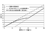
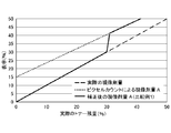
具体的に説明すると、トナー残量A1(%)≧トナー残量B(%)のときには、図5に示すように、トナー残量A(%)の値がトナー残量B(%)の値に徐々に近づく。上記式により、係数Kの値が1より大きくなるため、画像形成動作によって消費されたトナー消費量ΔA(%)が大きくなるように補正される。一方、トナー残量A1(%)<トナー残量B(%)ときにも、図6に示すように、トナー残量A(%)の値がトナー残量B(%)の値に徐々に近づく。上記式により、係数Kの値が1より小さくなるため、画像形成動作によって消費されたトナー消費量ΔA(%)が小さくなるように補正される。また、補正を行っていった結果、仮にトナー残量A1とトナー残量Bとの大小関係が入れ替わった場合でも、フローチャートのS108とS109に適宜進むことにより、トナー残量A1とトナー残量Bを近づけることができる。 Specifically, when the remaining amount of toner A1 (%) ≥ the remaining amount of toner B (%), the value of the remaining amount of toner A (%) is the value of the remaining amount of toner B (%) as shown in FIG. Gradually approach. According to the above equation, since the value of the coefficient K is larger than 1, the toner consumption ΔA (%) consumed by the image forming operation is corrected to be large. On the other hand, even when the remaining amount of toner A1 (%) <remaining amount of toner B (%), the value of the remaining amount of toner A (%) gradually becomes the value of the remaining amount of toner B (%) as shown in FIG. Get closer. According to the above equation, since the value of the coefficient K is smaller than 1, the toner consumption ΔA (%) consumed by the image forming operation is corrected to be small. Further, even if the magnitude relationship between the remaining amount of toner A1 and the remaining amount of toner B is exchanged as a result of performing the correction, the remaining amount of toner A1 and the remaining amount of toner B can be appropriately advanced to S108 and S109 of the flowchart. Can be brought closer.
また、本実施例では、トナー残量B(%)の値が実際のトナー残量の値と近くなる範囲(本実施例では10〜30%)において、トナー残量A(%)の値をトナー残量B(%)に収束させている。そのため、トナー残量B(%)の値が実際のトナー残量の値と近くなる範囲外である場合(トナー残量B(%)=10(%)となった後)に、トナー残量A(%)の値を補正しなくとも、精度よく、現像剤収納容器内のトナー残量を検出することができる。
また、現像剤収納容器内のトナー残量が少なくなることで、検出部Bによる検出精度が悪くなる場合には、トナー残量が多い時にトナー残量A(%)の値がトナー残量B(%)に収束した時点で、係数Kの値を固定するようにしてもよい。
Further, in this embodiment, the value of the remaining amount of toner A (%) is set in the range where the value of the remaining amount of toner B (%) is close to the value of the remaining amount of toner (10 to 30% in this embodiment). It is converged to the remaining amount of toner B (%). Therefore, when the value of the remaining amount of toner B (%) is outside the range close to the value of the remaining amount of toner (after the remaining amount of toner B (%) = 10 (%)), the remaining amount of toner is reached. The remaining amount of toner in the developer storage container can be detected accurately without correcting the value of A (%).
Further, when the detection accuracy by the detection unit B deteriorates due to the decrease in the remaining amount of toner in the developer storage container, the value of the remaining amount of toner A (%) becomes the remaining amount of toner B when the remaining amount of toner is large. The value of the coefficient K may be fixed when it converges to (%).
<比較例1について>
現像剤収納容器内のトナー残量を検出するためのハードウェア構成は実施例1と同じである。
(トナー残量表示の制御)
比較例1では、ピクセルカウントを用いて検出されたトナー残量A、または、電極22と電極23との間の静電容量を用いて検出されたトナー残量Bが30(%)に到達した時点において、
(1):トナー残量A1(%)≧トナー残量B(%)のときは、現像剤収納容器内のトナー残量をトナー残量B(%)として表示する。
(2):トナー残量A1(%)<トナー残量B(%)のときは、トナー残量Aの値によらず、現像剤収納容器内のトナー残量を30%として表示する。そして、トナー残量B(%)=30(%)になった時点で、現像剤収納容器内のトナー残量をトナー残量B(%)として表示する。
<About Comparative Example 1>
The hardware configuration for detecting the remaining amount of toner in the developer storage container is the same as that in the first embodiment.
(Control of toner level display)
In Comparative Example 1, the remaining amount of toner A detected by using the pixel count or the remaining amount of toner B detected by using the capacitance between the
(1): When the remaining amount of toner A1 (%) ≥ the remaining amount of toner B (%), the remaining amount of toner in the developer storage container is displayed as the remaining amount of toner B (%).
(2): When the remaining amount of toner A1 (%) <remaining amount of toner B (%), the remaining amount of toner in the developer storage container is displayed as 30% regardless of the value of the remaining amount of toner A. Then, when the remaining amount of toner B (%) = 30 (%), the remaining amount of toner in the developer storage container is displayed as the remaining amount of toner B (%).
(比較例1の評価結果)
比較例1における(1)の場合については、上述したように、トナー残量Bが30(%)に到達した時点において、現像剤収納容器内のトナー残量がトナー残量B(%)として表示される。つまり、トナー残量Bが30(%)となるまでは、現像剤収納容器内のトナー残量がトナー残量A(%)(A1(%)−ΔA(%))として表示されるが、現像剤収納容器内のトナー残量の表示がトナー残量B(%)に切り替わる。しかし、トナー残量Bが30(%)に到達した時点において、トナー残量の表示が実際のトナー残量と近くなるものの、突然トナー残量が変化してしまう。具体的には、図7に示すように、トナー残量Bが30(%)に到達した時点において、表示部は現像剤収納容器内のトナー残量が急に
減ったように検出し、表示してしまう。
(Evaluation result of Comparative Example 1)
In the case of (1) in Comparative Example 1, as described above, when the remaining amount of toner B reaches 30 (%), the remaining amount of toner in the developer storage container is regarded as the remaining amount of toner B (%). Is displayed. That is, until the remaining amount of toner B reaches 30 (%), the remaining amount of toner in the developer storage container is displayed as the remaining amount of toner A (%) (A1 (%) −ΔA (%)). The display of the remaining amount of toner in the developer storage container is switched to the remaining amount of toner B (%). However, when the remaining amount of toner B reaches 30 (%), the remaining amount of toner is displayed close to the actual remaining amount of toner, but the remaining amount of toner suddenly changes. Specifically, as shown in FIG. 7, when the remaining amount of toner B reaches 30 (%), the display unit detects and displays that the remaining amount of toner in the developer storage container has suddenly decreased. Resulting in.
一方、比較例1における(2)の場合については、上述したように、トナー残量Bが30(%)に到達した時点において、トナー残量Aの値によらず、現像剤収納容器内のトナー残量を30%として表示する。そして、トナー残量B(%)=30(%)になった時点で、現像剤収納容器内のトナー残量をトナー残量B(%)として表示する。そのため、図8に示すように、一定期間、画像形成動作を繰り返しても現像剤収納容器内のトナー残量が減らないような表示となってしまう。 On the other hand, in the case of (2) in Comparative Example 1, as described above, when the remaining amount of toner B reaches 30 (%), the amount of the remaining amount of toner A does not depend on the value of the remaining amount of toner A. The remaining amount of toner is displayed as 30%. Then, when the remaining amount of toner B (%) = 30 (%), the remaining amount of toner in the developer storage container is displayed as the remaining amount of toner B (%). Therefore, as shown in FIG. 8, the display is such that the remaining amount of toner in the developer storage container does not decrease even if the image forming operation is repeated for a certain period of time.
<比較例2の構成>
現像剤収納容器内のトナー残量を検出するためのハードウェア構成は実施例1と同じである。
(トナー残量表示の制御)
比較例2では、ピクセルカウントを用いて検出されたトナー残量Aが40(%)に到達した時点において、
トナー残量A1(%)≧トナー残量B(%)のときは、以下の補正式を用いて、現像剤収納容器内のトナー残量を算出し、その算出結果をユーザーに表示する。ここで、比較例1において、A(%)とA1(%)とΔA(%)の定義は実施例1と同様である。
A(%)=A1(%)−1.2×ΔA(%)
一方、比較例2において、トナー残量A(%)<トナー残量B(%)のときは、そのまま、現像剤収納容器内のトナー残量をトナー残量A(%)(A1(%)−ΔA(%))として表示する。
<Structure of Comparative Example 2>
The hardware configuration for detecting the remaining amount of toner in the developer storage container is the same as that in the first embodiment.
(Control of toner level display)
In Comparative Example 2, when the remaining amount of toner A detected by using the pixel count reaches 40 (%),
When the remaining amount of toner A1 (%) ≥ the remaining amount of toner B (%), the remaining amount of toner in the developer storage container is calculated using the following correction formula, and the calculation result is displayed to the user. Here, in Comparative Example 1, the definitions of A (%), A1 (%), and ΔA (%) are the same as those in Example 1.
A (%) = A1 (%) -1.2 x ΔA (%)
On the other hand, in Comparative Example 2, when the remaining amount of toner A (%) <the remaining amount of toner B (%), the remaining amount of toner in the developer storage container is used as it is as the remaining amount of toner A (%) (A1 (%)). It is displayed as −ΔA (%)).
(比較例2の評価結果)
比較例2においては、上述したように、トナー残量A1(%)≧トナー残量B(%)のときは、上記式に示すように、画像形成動作によって消費されたトナー量が多くなるように補正される。そのため、トナー残量A(%)の値がトナー残量B(%)に徐々に近づくことになる。しかし、最終的に、トナー残量A(%)の値がトナー残量B(%)に到達しないため、トナー残量の表示が0(ゼロ)になる前に、現像剤収納容器内のトナー残量が0となってしまう。
(Evaluation result of Comparative Example 2)
In Comparative Example 2, as described above, when the remaining amount of toner A1 (%) ≥ the remaining amount of toner B (%), the amount of toner consumed by the image forming operation is increased as shown in the above equation. Is corrected to. Therefore, the value of the remaining toner amount A (%) gradually approaches the remaining amount of toner B (%). However, since the value of the remaining amount of toner A (%) does not finally reach the remaining amount of toner B (%), the toner in the developer storage container is before the display of the remaining amount of toner becomes 0 (zero). The remaining amount becomes 0.
<比較例3の構成>
現像剤収納容器内のトナー残量を検出するためのハードウェア構成は実施例1と同じである。
(トナー残量表示の制御)
比較例3では、ピクセルカウントを用いて検出されたトナー残量A、または、電極22と電極23との間の静電容量を用いて検出されたトナー残量Bが30(%)に到達した時点において、
トナー残量A1(%)≧トナー残量B(%)のときは、以下の補正式を用いて、現像剤収納容器内のトナー残量を算出し、その算出結果をユーザーに表示する。
A(%)=A1(%)−2×ΔA(%)
一方、比較例3において、トナー残量A1(%)<トナー残量B(%)のときは、そのまま、現像剤収納容器内のトナー残量をトナー残量A(%)として表示する。
<Structure of Comparative Example 3>
The hardware configuration for detecting the remaining amount of toner in the developer storage container is the same as that in the first embodiment.
(Control of toner level display)
In Comparative Example 3, the remaining amount of toner A detected by using the pixel count or the remaining amount of toner B detected by using the capacitance between the
When the remaining amount of toner A1 (%) ≥ the remaining amount of toner B (%), the remaining amount of toner in the developer storage container is calculated using the following correction formula, and the calculation result is displayed to the user.
A (%) = A1 (%) -2 x ΔA (%)
On the other hand, in Comparative Example 3, when the remaining amount of toner A1 (%) <the remaining amount of toner B (%), the remaining amount of toner in the developer storage container is displayed as the remaining amount of toner A (%).
(比較例3の評価結果)
比較例3においては、上述したように、トナー残量A1(%)≧トナー残量B(%)のときは、上記式に示すように、画像形成動作によって消費されたトナー量が多くなるように補正される。しかし、比較例3では、トナー残量A(%)の値がトナー残量B(%)に対して急に近づくことになり、トナー残量B(%)が0(ゼロ)になる前に、トナー残量A(%)の値がトナー残量B(%)の値に到達してしまう。そのため、図10に示すよう
に、トナー残量A(%)の値がトナー残量B(%)の値に到達した後において、トナー残量の表示が上がったり下がったりしてしまう。なお、本実施例では、現像剤収納容器内のトナーは、撹拌部材43によって撹拌されて移動するため、トナー残量B(%)の値に誤差(振れ)が発生する場合がある。特に、本実施例のように、トナーを持ち上げることで現像剤収納器内のトナーを撹拌する構成では、トナー残量B(%)の値に誤差(振れ)が発生する場合がある。
(Evaluation result of Comparative Example 3)
In Comparative Example 3, as described above, when the remaining amount of toner A1 (%) ≥ the remaining amount of toner B (%), the amount of toner consumed by the image forming operation increases as shown in the above equation. Is corrected to. However, in Comparative Example 3, the value of the remaining toner amount A (%) suddenly approaches the remaining amount of toner B (%), and before the remaining amount of toner B (%) becomes 0 (zero). , The value of the remaining amount of toner A (%) reaches the value of the remaining amount of toner B (%). Therefore, as shown in FIG. 10, after the value of the remaining amount of toner A (%) reaches the value of the remaining amount of toner B (%), the display of the remaining amount of toner goes up or down. In this embodiment, since the toner in the developer storage container is agitated and moved by the stirring
以上のように、本実施例では、トナー残量B(%)=30(%)に到達した時点において、トナー残量A(%)の値がトナー残量B(%)の値に徐々に近づくように、トナー残量A(%)の値を補正している。そのため、トナー残量B(%)=30(%)に到達した時点で、トナー残量の表示が急に切り替わることがない。すなわち、トナー残量の報知に用いられる検出結果の精度を向上させることができる。また、トナー残量の報知に用いられる検出結果が急激に変動することを抑制することができる。 As described above, in this embodiment, when the remaining amount of toner B (%) = 30 (%) is reached, the value of the remaining amount of toner A (%) gradually becomes the value of the remaining amount of toner B (%). The value of the remaining amount of toner A (%) is corrected so as to approach it. Therefore, when the remaining amount of toner B (%) = 30 (%) is reached, the display of the remaining amount of toner does not suddenly switch. That is, the accuracy of the detection result used for notifying the remaining amount of toner can be improved. In addition, it is possible to prevent the detection result used for notifying the remaining amount of toner from suddenly fluctuating.
(実施例2)
次に、実施例2について説明する。実施例2では、画像形成装置は、図11に示すように、電極間の静電容量を用いて現像剤収納器内のトナー残量を検出する検出部D(電極22、電極23、高圧電源24、電流検出回路125)を有している。また、検出部E(電極23、電極29、高圧電源24、電流検出回路225)を有している。ここで、本実施例において、実施例1と同一の機能を有する部分については、同一の符号を付すことでその説明を省略する。
(Example 2)
Next, Example 2 will be described. In the second embodiment, as shown in FIG. 11, the image forming apparatus uses the capacitance between the electrodes to detect the remaining amount of toner in the developer storage device D (
上述したように、本実施例では、画像形成装置は、電極間の静電容量を用いて現像剤収納器内のトナー残量を検出する検出部Dと検出部Eを有している。検出部Dは、現像剤収納器内のトナー残量が5〜15(%)となる場合において、現像剤収納器内のトナー残量を検出することができる。また、検出部Eは、現像剤収納器内のトナー残量が10〜40(%)となる場合において、現像剤収納器内のトナー残量を検出することができる。なお、検出部Dと検出部Eが、実施例1における検出部Bに相当する。検出部Dの検出したトナー残量Dと、検出部Eの検出したトナー残量Eが、実施例1における検出部Bの検出したトナー残量Bに相当する。
すなわち、検出部Eの検出範囲上限側の閾値E0は、40%であり、検出範囲の下限側の閾値Ezは10(%)である。検出部Dの検出範囲上限側の閾値D0は15%であり、検出範囲の下限側の閾値Dzは5(%)である。
As described above, in this embodiment, the image forming apparatus includes a detection unit D and a detection unit E that detect the remaining amount of toner in the developer storage device by using the capacitance between the electrodes. The detection unit D can detect the remaining amount of toner in the developer storage device when the remaining amount of toner in the developer storage device is 5 to 15 (%). Further, the detection unit E can detect the remaining amount of toner in the developer storage device when the remaining amount of toner in the developer storage device is 10 to 40 (%). The detection unit D and the detection unit E correspond to the detection unit B in the first embodiment. The remaining amount of toner D detected by the detection unit D and the remaining amount of toner E detected by the detection unit E correspond to the remaining amount of toner B detected by the detection unit B in the first embodiment.
That is, the threshold value E0 on the upper limit side of the detection range of the detection unit E is 40%, and the threshold value Ez on the lower limit side of the detection range is 10 (%). The threshold value D0 on the upper limit side of the detection range of the detection unit D is 15%, and the threshold value Dz on the lower limit side of the detection range is 5 (%).
本実施例では、実施例1と同様に、カートリッジが使用され始めた期間においては、ユーザーに対し、ピクセルカウントを用いて検出されたトナー残量が表示される。そして、現像剤収納器内のトナー残量が40(%)以下となる場合においては、検出部Eによって検出されたトナー残量Eに基づいて、ユーザーに表示されるトナー残量Aの値をトナー残量Eの値に近づける。その後、現像剤収納器内のトナー残量が15(%)以下となる場合においては、検出部を検出部Eから検出部Dに切り替えて、検出部Dによって検出されたトナー残量Dに基づいて、ユーザーに表示されるトナー残量Aの値をトナー残量Dの値に近づける。そして、検出部Dと検出部Eの両方の検出範囲外であるときは、係数Kを1とする。 In this embodiment, as in the first embodiment, the remaining amount of toner detected by using the pixel count is displayed to the user during the period when the cartridge is started to be used. Then, when the remaining amount of toner in the developer storage device is 40 (%) or less, the value of the remaining amount of toner A displayed to the user is set based on the remaining amount E of toner detected by the detection unit E. Bring the toner level closer to the value of E. After that, when the remaining amount of toner in the developer container becomes 15 (%) or less, the detection unit is switched from the detection unit E to the detection unit D, and based on the remaining amount of toner D detected by the detection unit D. Then, the value of the remaining amount of toner A displayed to the user is brought close to the value of the remaining amount of toner D. Then, when it is out of the detection range of both the detection unit D and the detection unit E, the coefficient K is set to 1.
(検出部Eの検出結果に基づく補正)
本実施例では、トナー残量が40(%)以下となる場合において、検出部Aによって検出されるトナー残量A1(%)が、検出部Eによって検出されるトナー残量E(%)よりも小さい場合は、以下の式を用いて係数Kの値を変更する。これにより、トナー残量A(%)の値を補正する。なお、本実施例においても、実施例1と同様に、現像剤収納器内のトナー残量は、A(%)=A1(%)−K×ΔA(%)という式を用いて検出される。
K=5/(E(%)−A1(%)+5)
一方、トナー残量が40(%)以下となる場合において、検出部Aによって検出されるトナー残量A1(%)が、検出部Eによって検出されるトナー残量E(%)以上である場合は、以下の式を用いて係数Kの値を変更する。これにより、トナー残量A(%)の値を補正する。
K=(A1(%)−E(%)+5)/5
(Correction based on the detection result of the detection unit E)
In this embodiment, when the remaining amount of toner is 40 (%) or less, the remaining amount of toner A1 (%) detected by the detection unit A is larger than the remaining amount of toner E (%) detected by the detection unit E. If is also small, the value of the coefficient K is changed using the following formula. As a result, the value of the remaining toner amount A (%) is corrected. In this embodiment as well, similarly to the first embodiment, the remaining amount of toner in the developer storage device is detected by using the formula A (%) = A1 (%) −K × ΔA (%). ..
K = 5 / (E (%) -A1 (%) + 5)
On the other hand, when the remaining amount of toner is 40 (%) or less, the remaining amount of toner A1 (%) detected by the detection unit A is equal to or more than the remaining amount E (%) of the toner detected by the detection unit E. Changes the value of the coefficient K using the following equation. As a result, the value of the remaining toner amount A (%) is corrected.
K = (A1 (%) -E (%) + 5) / 5
(検出部Dの検出結果に基づく補正)
また、本実施例では、トナー残量が15(%)以下となる場合において、検出部Aによって検出されるトナー残量A1(%)が、検出部Dによって検出されるトナー残量D(%)よりも小さい場合は、以下の式を用いて係数Kの値を変更する。これにより、トナー残量A(%)の値を補正する。
K=2/(D(%)−A1(%)+2)
一方、トナー残量が15(%)以下となる場合において、検出部Aによって検出されるトナー残量A1(%)が、検出部Dによって検出されるトナー残量D(%)以上である場合は、以下の式を用いて係数Kの値を変更する。これにより、トナー残量A(%)の値を補正する。
K=(A1(%)−D(%)+2)/2
本実施例では、検出部Eよりも検出部Dの検出精度が高い。したがって、係数Kを求める式中の定数を、検出部Dに係るものは2として、検出部Eに係るものは5とした。これによって、検出部Dの検出結果を用いる補正は、検出部Eの検出結果を用いる補正よりも、トナー消費量ΔAを大きく補正して、検出部Aの検出したトナー残量が、早く検出部Dの検出結果と一致するようにする。また、検出部Eの検出結果に基づいて補正した値を、さらに精度の高い検出部Dの検出結果に基づいて補正することで、より精度の高いトナー残量が検出可能になる。
図13は本実施例の構成を用いた現像剤収納容器内のトナー残量を検出する流れを説明したものである。実施例1と異なる部分について、主に説明する。
S204において、検出部Eの検出したトナー残量Eが、検出部Eの検出上限閾値E0以下であるかの判断を行う。Yesの場合はS205にすすむ。Noの場合はS407に進む。
次にS205において、検出部Dの検出したトナー残量Dが、検出部Dの検出上限閾値D0以下であるかの判断を行う。Noの場合は検出部Eによる補正を行うため、S206に進む。そして、S206、S208、S209において、検出部Eの検出結果を用いて、係数Kを補正する。S205の判断結果がYesの場合は、検出部Dによる補正を行うため、S305に進む。
S305においては、検出部Dの検出したトナー残量Dが、検出部Dの検出下限閾値Dz以上であるかの判断を行う。Noの場合はS407に進む。Yesの場合は、検出部Dによる補正を行うため、S306に進む。そして、S306、S308、S309において、検出部Eの検出結果を用いて、係数Kを補正する。
以降の流れは実施例1と同じであるため、説明を省略する。なお、S407に進んだ場合は、係数Kを1として、消費量ΔAに対する補正を行わない。
上記の説明では、検出部Dと検出部Eの検出可能な範囲が重複していた。一方で、検出部Dと検出部Eの検出範囲が重複していない時は、以下のようにして消費量ΔAの上補正を行うことができる。
例えば、検出部Dは、現像剤収納器内のトナー残量が5〜15(%)の範囲において、現像剤収納器内のトナー残量を検出することができるものとする。また、検出部Eは、現像剤収納器内のトナー残量が20〜40(%)の範囲において、現像剤収納器内のトナー残量を検出することができるものとする。
すなわち、検出部Eの検出範囲上限側の閾値E0は40%であり、検出範囲の下限側の閾値Ezは20(%)である。検出部Dの検出範囲上限側の閾値D0は15%であり、検
出範囲の下限側の閾値Dzは5(%)である。
カートリッジが使用され始めた期間においては、ユーザーに対し、ピクセルカウントを用いて検出されたトナー残量が表示される。そして、現像剤収納器内のトナー残量が20〜40(%)となる場合においては、検出部Eによって検出されたトナー残量Eに基づいて、ユーザーに表示されるトナー残量Aの値をトナー残量Eの値に近づける。その後、現像剤収納器内のトナー残量が5〜15(%)となる場合においては、検出部Dによって検出されたトナー残量Dに基づいて、ユーザーに表示されるトナー残量Aの値をトナー残量Dの値に近づける。そして、検出部Dと検出部Eの両方の検出範囲外であるときは、係数Kを1とする。検出部Eの検出部に基づく補正と、検出部Dの検出部に基づく補正に用いる式(係数Kを求める式)は、上述したものと同じであるので、ここでは説明を省略する。
図14は、この場合の現像剤収納容器内のトナー残量を検出する流れを説明したものである。実施例1と異なる部分について、主に説明する。
S204において、検出部Eの検出したトナー残量Eが、検出部Eの検出上限閾値E0以下であるかの判断を行う。Yesの場合はS205にすすむ。Noの場合はS407に進む。
次にS205において、検出部Eの検出したトナー残量Eが、検出部Eの検出下限閾値Ez以下であるかの判断を行う。Yesの場合は、検出部Eによる補正を行うため、S206に進む。そして、S206、S208、S209において、検出部Eの検出結果を用いて、係数Kを補正する。S205における判断がNoの場合は、検出部Dによる補正を行うかどうかを判断するため、S304に進む。
S304においては、検出部Dの検出したトナー残量Dが、検出部Dの検出上限閾値D0以下であるかの判断を行う。Yesの場合は、S305に進む。Noの場合は、S407に進む。
S305においては、検出部Dの検出したトナー残量Dが、検出部Dの検出下限閾値Dz以上であるかの判断を行う。Noの場合は、S407に進む。Yesの場合は、検出部Dによる補正を行うため、S306に進む。そして、S306、S308、S309において、検出部Eの検出結果を用いて、係数Kを補正する。
以降の流れは実施例1と同じであるため、説明を省略する。なお、S407に進んだ場合は、係数Kを1として、消費量ΔAに対する補正を行わない。
(Correction based on the detection result of detection unit D)
Further, in this embodiment, when the remaining amount of toner is 15 (%) or less, the remaining amount of toner A1 (%) detected by the detection unit A is the remaining amount D (%) of the remaining amount of toner detected by the detection unit D. ), The value of the coefficient K is changed using the following formula. As a result, the value of the remaining toner amount A (%) is corrected.
K = 2 / (D (%) -A1 (%) + 2)
On the other hand, when the remaining amount of toner is 15 (%) or less, the remaining amount of toner A1 (%) detected by the detection unit A is equal to or more than the remaining amount D (%) of the toner detected by the detection unit D. Changes the value of the coefficient K using the following equation. As a result, the value of the remaining toner amount A (%) is corrected.
K = (A1 (%) -D (%) +2) / 2
In this embodiment, the detection accuracy of the detection unit D is higher than that of the detection unit E. Therefore, the constant in the formula for obtaining the coefficient K was set to 2 for the detection unit D and 5 for the detection unit E. As a result, the correction using the detection result of the detection unit D corrects the toner consumption ΔA more than the correction using the detection result of the detection unit E, and the remaining amount of toner detected by the detection unit A is faster than the detection unit. Make sure that it matches the detection result of D. Further, by correcting the value corrected based on the detection result of the detection unit E based on the detection result of the detection unit D with higher accuracy, the remaining amount of toner with higher accuracy can be detected.
FIG. 13 illustrates a flow of detecting the remaining amount of toner in the developer storage container using the configuration of this embodiment. The part different from the first embodiment will be mainly described.
In S204, it is determined whether or not the remaining amount of toner E detected by the detection unit E is equal to or less than the detection upper limit threshold value E0 of the detection unit E. In the case of Yes, proceed to S205. If No, the process proceeds to S407.
Next, in S205, it is determined whether or not the remaining amount D of toner detected by the detection unit D is equal to or less than the detection upper limit threshold value D0 of the detection unit D. If No, the detection unit E makes a correction, so the process proceeds to S206. Then, in S206, S208, and S209, the coefficient K is corrected by using the detection result of the detection unit E. If the determination result in S205 is Yes, the process proceeds to S305 in order to make a correction by the detection unit D.
In S305, it is determined whether or not the remaining amount D of toner detected by the detection unit D is equal to or greater than the detection lower limit threshold value Dz of the detection unit D. If No, the process proceeds to S407. In the case of Yes, the process proceeds to S306 in order to perform correction by the detection unit D. Then, in S306, S308, and S309, the coefficient K is corrected by using the detection result of the detection unit E.
Since the subsequent flow is the same as that of the first embodiment, the description thereof will be omitted. When the process proceeds to S407, the coefficient K is set to 1, and the consumption amount ΔA is not corrected.
In the above description, the detectable range of the detection unit D and the detection unit E overlaps. On the other hand, when the detection ranges of the detection unit D and the detection unit E do not overlap, the consumption amount ΔA can be corrected as follows.
For example, the detection unit D can detect the remaining amount of toner in the developer storage device in the range of 5 to 15 (%) of the remaining amount of toner in the developer storage device. Further, the detection unit E can detect the remaining amount of toner in the developer storage device in the range of 20 to 40 (%).
That is, the threshold value E0 on the upper limit side of the detection range of the detection unit E is 40%, and the threshold value Ez on the lower limit side of the detection range is 20 (%). The threshold value D0 on the upper limit side of the detection range of the detection unit D is 15%, and the threshold value Dz on the lower limit side of the detection range is 5 (%).
During the period when the cartridge has been used, the user is shown the amount of toner remaining detected using the pixel count. Then, when the remaining amount of toner in the developer storage device is 20 to 40 (%), the value of the remaining amount of toner A displayed to the user based on the remaining amount of toner E detected by the detection unit E. Is close to the value of the remaining amount of toner E. After that, when the remaining amount of toner in the developer container becomes 5 to 15 (%), the value of the remaining amount of toner A displayed to the user based on the remaining amount D of toner detected by the detection unit D. Is close to the value of the remaining amount of toner D. Then, when it is out of the detection range of both the detection unit D and the detection unit E, the coefficient K is set to 1. The equations used for the correction based on the detection unit of the detection unit E and the correction based on the detection unit of the detection unit D (the equation for obtaining the coefficient K) are the same as those described above, and thus the description thereof will be omitted here.
FIG. 14 illustrates the flow of detecting the remaining amount of toner in the developer storage container in this case. The part different from the first embodiment will be mainly described.
In S204, it is determined whether or not the remaining amount of toner E detected by the detection unit E is equal to or less than the detection upper limit threshold value E0 of the detection unit E. In the case of Yes, proceed to S205. If No, the process proceeds to S407.
Next, in S205, it is determined whether or not the remaining amount of toner E detected by the detection unit E is equal to or less than the detection lower limit threshold value Ez of the detection unit E. In the case of Yes, the process proceeds to S206 in order to make a correction by the detection unit E. Then, in S206, S208, and S209, the coefficient K is corrected by using the detection result of the detection unit E. If the determination in S205 is No, the process proceeds to S304 in order to determine whether or not to perform correction by the detection unit D.
In S304, it is determined whether or not the remaining amount D of toner detected by the detection unit D is equal to or less than the detection upper limit threshold value D0 of the detection unit D. In the case of Yes, the process proceeds to S305. If No, the process proceeds to S407.
In S305, it is determined whether or not the remaining amount D of toner detected by the detection unit D is equal to or greater than the detection lower limit threshold value Dz of the detection unit D. If No, the process proceeds to S407. In the case of Yes, the process proceeds to S306 in order to perform correction by the detection unit D. Then, in S306, S308, and S309, the coefficient K is corrected by using the detection result of the detection unit E.
Since the subsequent flow is the same as that of the first embodiment, the description thereof will be omitted. When the process proceeds to S407, the coefficient K is set to 1, and the consumption amount ΔA is not corrected.
以上のように、本実施例では、実施例1と同様に、トナー残量A(%)の値がトナー残量D(%)(E(%))の値に徐々に近づくように、トナー残量A(%)の値が補正される。そのため、トナー残量D(%)(E(%))が所定の残量に到達した時点で、トナー残量の検出結果と、表示が急に変動することがない。すなわち、トナー残量の報知に用いられる検出結果の精度を向上させることができる。また、トナー残量の報知に用いられる検出結果が急激に変動することを抑制することができる。 As described above, in the present embodiment, as in the first embodiment, the toner so that the value of the remaining amount of toner A (%) gradually approaches the value of the remaining amount of toner D (%) (E (%)). The value of the remaining amount A (%) is corrected. Therefore, when the remaining amount of toner D (%) (E (%)) reaches a predetermined remaining amount, the detection result of the remaining amount of toner and the display do not suddenly change. That is, the accuracy of the detection result used for notifying the remaining amount of toner can be improved. In addition, it is possible to prevent the detection result used for notifying the remaining amount of toner from suddenly fluctuating.
なお、各実施例において、検出部Aは、ピクセルカウントを用いてトナー残量を検出したが、必ずしもこれに限られることはない。例えば、検出部Aは、露光装置20が感光ドラム1を露光した総時間に基づいて、現像剤収納容器内のトナー残量を検出してもよい。また、本実施例では、検出部B(検出部D、Eも同じ)は、2つの電極間の静電容量を用いてトナー残量を検出したが、必ずしもこれに限られることはない。例えば、検出部Bは、現像剤収納容器内を通過する光の透過量を測定することで、現像剤収納容器内のトナー残量を検出してもよい。また、例えば、検出部Bは、現像剤収納容器内を通過する光が受光素子に到達する時間の変化を測定することで、現像剤収納容器内のトナー残量を検出してもよい。また、例えば、検出部Bは、現像剤収納容器内に配置された透磁率センサや圧力センサを用いて、現像剤収納容器内のトナー残量を検出してもよい。
In each embodiment, the detection unit A detects the remaining amount of toner by using the pixel count, but the present invention is not necessarily limited to this. For example, the detection unit A may detect the remaining amount of toner in the developer storage container based on the total time that the
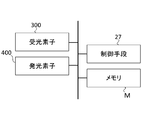
この場合、画像形成装置には、図12に示すように、現像剤収納容器内に光を発光する
発光素子(発光部材)400と、現像剤収納容器内を通過した光を受光する受光素子(受光部材)300とが設けられる。そして、検出部Bは、トナー残量Bを、受光部材300が受光した光の強度とトナー残量Bとの関係とに基づいて検出する。この場合、具体的には、メモリM1には、受光部材300が受光した光の強度とトナー残量Bとの関係(第3関係に対応)があらかじめ記憶される。そして、検出部Bは、トナー残量Bを、メモリMに記憶されたその関係に基づいて検出する。また、光が受光素子に到達する時間の変化を測定することでトナー残量が検出される場合においても、同様の方法でトナー残量Bが検出される。
In this case, as shown in FIG. 12, the image forming apparatus includes a light emitting element (light emitting member) 400 that emits light in the developer storage container and a light receiving element (light receiving element) that receives light that has passed through the developer storage container. A light receiving member) 300 is provided. Then, the detection unit B detects the remaining amount of toner B based on the relationship between the intensity of the light received by the
また、各実施例において、トナー残量Aを補正するための係数Kは計算式を用いて求められているが、必ずしもこれに限定されない。例えば、トナー残量Aを補正するための係数Kはテーブルを用いて求められてもよい。
また、各実施例において、環境(温度や湿度)に応じて、トナー残量A(%)の値を補正するための補正式を変更してもよい。また、同様に、現像剤収納器内のトナーの色や種類などに応じて、トナー残量A(%)の値を補正するための補正式を変更してもよい。
また、各実施例では、係数Kを求めるための計算式において、トナー残量B(%)として、前回の画像形成動作後におけるトナー残量B(%)の値を用いてもよい。また、係数Kを求めるための計算式において、トナー残量B(%)として、今回の画像形成動作後におけるトナー残量B(%)の値を用いてもよい。
Further, in each embodiment, the coefficient K for correcting the remaining amount of toner A is obtained by using a calculation formula, but the coefficient K is not necessarily limited to this. For example, the coefficient K for correcting the remaining amount of toner A may be obtained using a table.
Further, in each embodiment, the correction formula for correcting the value of the remaining amount of toner A (%) may be changed according to the environment (temperature and humidity). Similarly, the correction formula for correcting the value of the remaining amount of toner A (%) may be changed according to the color and type of the toner in the developer storage device.
Further, in each embodiment, the value of the toner remaining amount B (%) after the previous image forming operation may be used as the toner remaining amount B (%) in the calculation formula for obtaining the coefficient K. Further, in the calculation formula for obtaining the coefficient K, the value of the remaining amount of toner B (%) after the current image forming operation may be used as the remaining amount of toner B (%).
また、各実施例において、トナー残量A(%)「≧」トナー残量B(%)の場合と、トナー残量A(%)「<」トナー残量B(%)の場合とで、係数Kを求めるための式が異なっているが、必ずしもこれに限られることはない。例えば、トナー残量A(%)「>」トナー残量B(%)の場合と、トナー残量A(%)「≦」トナー残量B(%)の場合とで、係数Kを求めるための式を変えてもよい。 Further, in each embodiment, there are cases where the toner remaining amount A (%) “≧” toner remaining amount B (%) and the toner remaining amount A (%) “<” toner remaining amount B (%). The formula for obtaining the coefficient K is different, but it is not necessarily limited to this. For example, in order to obtain the coefficient K in the case of the toner remaining amount A (%) ">" toner remaining amount B (%) and the case of the toner remaining amount A (%) "≤" toner remaining amount B (%). You may change the formula of.
26…表示手段、100…画像形成装置、A…検出部、B…検出部、S…シート
26 ... Display means, 100 ... Image forming apparatus, A ... Detection unit, B ... Detection unit, S ... Sheet
Claims (9)
今回の画像形成動作が実行された後に現像剤容器内に残る現像剤量を残量Aとし、前回の画像形成動作が実行された後に前記現像剤容器内に残る現像剤量を残量A1とし、今回の画像形成動作で消費された現像剤量を消費量ΔAとし、正の数からなる第一の係数をkとした場合に、前記残量AをA=A1−k×ΔAとして取得する第1取得部と、
前回または今回の画像形成動作が実行された後に前記現像剤容器内に残る現像剤量を残量Bとして取得する第2取得部と、
前記残量Aをユーザーに報知する報知部と、
前記残量Bが第1閾値以下で且つ前記第1閾値よりも値が小さい第2閾値以上である場合に、前記残量Bの値に前記残量Aを近づけるように前記第一の係数kを補正し、前記残量Bが前記第1閾値より大きい場合又は前記第2閾値より小さい場合には前記第一の係数kを1とする制御部と、
前記現像剤容器内に光を発光する発光部材と、
前記発光部材から発光され、前記現像剤容器内を通過した光を受光する受光部材と、
を有し、
前記制御部は、
前記残量A1≧前記残量Bである場合に、前記kが1以上となるように補正を行い、
前記残量A1<前記残量Bである場合に、前記kが1未満となるように補正を行い、
記録媒体に形成される画像は、複数の単位ドットが集まることで形成されており、
前記第1取得部は、前記消費量ΔAを、画像を構成する前記単位ドットの数と、前記単位ドットを形成するために消費される単位トナー量とに基づいて取得し、
前記第2取得部は、前記残量Bを、前記受光部材が受光した光の強度または受光した時間の長さと、前記現像剤容器内の現像剤の残量との第3関係とに基づいて取得すること
を特徴とする画像形成装置。 An image forming apparatus that forms an image on a recording medium using a developing agent contained in a developing agent container.
The amount of developer remaining in the developer container after the current image forming operation is executed is defined as the remaining amount A, and the amount of developer remaining in the developer container after the previous image forming operation is executed is defined as the remaining amount A1. When the amount of the developing agent consumed in the current image forming operation is the consumption amount ΔA and the first coefficient consisting of positive numbers is k, the remaining amount A is acquired as A = A1-k × ΔA. 1st acquisition department and
A second acquisition unit that acquires the amount of developer remaining in the developer container as the remaining amount B after the previous or current image forming operation is executed, and
A notification unit that notifies the user of the remaining amount A, and
When the remaining amount B is equal to or less than the first threshold value and is equal to or greater than the second threshold value having a value smaller than the first threshold value, the first coefficient k so as to bring the remaining amount A closer to the value of the remaining amount B. When the remaining amount B is larger than the first threshold value or smaller than the second threshold value , the control unit sets the first coefficient k to 1.
A light emitting member that emits light in the developer container,
A light receiving member that emits light from the light emitting member and receives light that has passed through the developer container.
Have,
The control unit
When the remaining amount A1 ≥ the remaining amount B, correction is performed so that the k is 1 or more.
When the remaining amount A1 <the remaining amount B, correction is performed so that the k is less than 1.
An image formed on a recording medium is formed by gathering a plurality of unit dots.
The first acquisition unit acquires the consumption amount ΔA based on the number of the unit dots constituting the image and the unit toner amount consumed to form the unit dots.
The second acquisition unit receives the remaining amount B based on the third relationship between the intensity of the light received by the light receiving member or the length of time the light is received and the remaining amount of the developer in the developing agent container. An image forming apparatus characterized in that it is acquired.
今回の画像形成動作が実行された後に現像剤容器内に残る現像剤量を残量Aとし、前回 The amount of developer remaining in the developer container after the current image forming operation is executed is defined as the remaining amount A, and the previous time is defined as the remaining amount A.
の画像形成動作が実行された後に前記現像剤容器内に残る現像剤量を残量A1とし、今回の画像形成動作で消費された現像剤量を消費量ΔAとし、正の数からなる第一の係数をkとした場合に、前記残量AをA=A1−k×ΔAとして取得する第1取得部と、The amount of the developer remaining in the developer container after the image forming operation of (1) is executed is defined as the remaining amount A1, the amount of the developer consumed in the current image forming operation is defined as the consumption amount ΔA, and the first consisting of positive numbers. When the coefficient of is k, the first acquisition unit that acquires the remaining amount A as A = A1-k × ΔA, and
前回または今回の画像形成動作が実行された後に前記現像剤容器内に残る現像剤量を残量Bとして取得する第2取得部と、 A second acquisition unit that acquires the amount of developer remaining in the developer container as the remaining amount B after the previous or current image forming operation is executed, and
前記残量Aをユーザーに報知する報知部と、 A notification unit that notifies the user of the remaining amount A, and
前記残量Bが第1閾値以下で且つ前記第1閾値よりも値が小さい第2閾値以上である場合に、前記残量Bの値に前記残量Aを近づけるように前記第一の係数kを補正し、前記残量Bが前記第1閾値より大きい場合又は前記第2閾値より小さい場合には前記第一の係数kを1とする制御部と、 When the remaining amount B is equal to or less than the first threshold value and is equal to or greater than the second threshold value having a value smaller than the first threshold value, the first coefficient k so as to bring the remaining amount A closer to the value of the remaining amount B. When the remaining amount B is larger than the first threshold value or smaller than the second threshold value, the control unit sets the first coefficient k to 1.
前記現像剤容器内に設けられる複数の電極と、 A plurality of electrodes provided in the developer container and
を有しHave
前記制御部は、 The control unit
前記残量A1≧前記残量Bである場合に、前記kが1以上となるように補正を行い、 When the remaining amount A1 ≥ the remaining amount B, correction is performed so that the k is 1 or more.
前記残量A1<前記残量Bである場合に、前記kが1未満となるように補正を行い、 When the remaining amount A1 <the remaining amount B, correction is performed so that the k is less than 1.
記録媒体に形成される画像は、複数の単位ドットが集まることで形成されており、 An image formed on a recording medium is formed by gathering a plurality of unit dots.
前記第1取得部は、前記消費量ΔAを、画像を構成する前記単位ドットの数と、前記単位ドットを形成するために消費される単位トナー量とに基づいて取得し、 The first acquisition unit acquires the consumption amount ΔA based on the number of the unit dots constituting the image and the unit toner amount consumed to form the unit dots.
前記第2取得部は、前記残量Bを、前記電極間の静電容量と、前記現像剤容器内の現像剤との第2関係とに基づいて取得することを特徴とする画像形成装置。 The second acquisition unit is an image forming apparatus that acquires the remaining amount B based on the second relationship between the capacitance between the electrodes and the developer in the developer container.
前記残量A1≧前記残量Bである場合に、k=(A1−B+n)/nとして前記残量Aを取得し、
前記残量A1<前記残量Bである場合に、k=n/(B−A1+n)として前記残量Aを取得することを特徴とする請求項1又は2に記載の画像形成装置。 The first acquisition unit, when n is a second coefficient consisting of a positive number,
When the remaining amount A1 ≥ the remaining amount B, the remaining amount A is acquired with k = (A1-B + n) / n.
The image forming apparatus according to claim 1 or 2 , wherein when the remaining amount A1 <the remaining amount B, the remaining amount A is acquired as k = n / (B-A1 + n).
前記記憶部には、前記単位ドットを形成するために消費される単位トナー量があらかじめ記憶され、
前記第1取得部は、前記記憶部に記憶された前記単位ドットを形成するために消費される単位トナー量に基づいて、前記消費量ΔAを取得することを特徴とする請求項1から3のいずれか1項に記載の画像形成装置。 It has a storage unit for storing information,
The storage unit stores in advance the amount of unit toner consumed to form the unit dots.
The first acquisition unit according to claims 1 to 3, wherein the first acquisition unit acquires the consumption amount ΔA based on the unit toner amount consumed to form the unit dots stored in the storage unit. The image forming apparatus according to any one item.
前記像担持体を露光することで、前記像担持体に静電潜像を形成する露光装置と、を有し、
前記第1取得部は、前記消費量ΔAを、前記露光装置が前記像担持体を露光する露光時間と、消費される現像剤量との第1関係に基づいて取得することを特徴とする請求項1から4のいずれか1項に記載の画像形成装置。 An image carrier on which a developer image is formed and
It has an exposure apparatus that forms an electrostatic latent image on the image carrier by exposing the image carrier.
The first acquisition unit is characterized in that the consumption amount ΔA is acquired based on the first relationship between the exposure time at which the exposure apparatus exposes the image carrier and the amount of the developer consumed. The image forming apparatus according to any one of Items 1 to 4.
前記記憶部には、前記露光装置が前記像担持体を露光する露光時間と、消費される現像剤量との前記第1関係があらかじめ記憶され、
前記第1取得部は、前記消費量ΔAを、前記第1関係に基づいて取得することを特徴とする請求項5に記載の画像形成装置。 It has a storage unit for storing information,
In the storage unit, the first relationship between the exposure time for the exposure apparatus to expose the image carrier and the amount of the developer consumed is stored in advance.
The image forming apparatus according to claim 5 , wherein the first acquisition unit acquires the consumption amount ΔA based on the first relationship.
前記記憶部には、前記電極間の静電容量と、前記現像剤容器内の現像剤との第2関係があらかじめ記憶され、
前記第2取得部は、前記残量Bを、前記第2関係に基づいて取得することを特徴とする請求項2に記載の画像形成装置。 It has a storage unit for storing information,
In the storage unit, the second relationship between the capacitance between the electrodes and the developer in the developer container is stored in advance.
The image forming apparatus according to claim 2 , wherein the second acquisition unit acquires the remaining amount B based on the second relationship.
前記記憶部には、前記受光部材が受光した光の強度または受光した時間の長さと、前記現像剤容器内の現像剤の残量との第3関係があらかじめ記憶され、
前記第2取得部は、前記残量Bを、前記第3関係に基づいて取得することを特徴とする請求項1に記載の画像形成装置。 It has a storage unit for storing information,
The storage unit stores in advance a third relationship between the intensity of the light received by the light receiving member or the length of time the light is received and the remaining amount of the developer in the developer container.
The image forming apparatus according to claim 1 , wherein the second acquisition unit acquires the remaining amount B based on the third relationship.
前記第1取得部によって取得された前記残量Aは、前記記憶部に記憶され、次の画像形成動作において、前記第1取得部が前記現像剤容器内の現像剤の残量を取得する際に、前記残量A1として用いられることを特徴とする請求項1又は2に記載の画像形成装置。
It has a storage unit for storing information,
The remaining amount A acquired by the first acquisition unit is stored in the storage unit, and when the first acquisition unit acquires the remaining amount of the developer in the developer container in the next image forming operation. The image forming apparatus according to claim 1 or 2 , wherein the image forming apparatus is used as the remaining amount A1.
Priority Applications (1)
| Application Number | Priority Date | Filing Date | Title |
|---|---|---|---|
| JP2016133440A JP6873619B2 (en) | 2016-07-05 | 2016-07-05 | Image forming device |
Applications Claiming Priority (1)
| Application Number | Priority Date | Filing Date | Title |
|---|---|---|---|
| JP2016133440A JP6873619B2 (en) | 2016-07-05 | 2016-07-05 | Image forming device |
Publications (3)
| Publication Number | Publication Date |
|---|---|
| JP2018005039A JP2018005039A (en) | 2018-01-11 |
| JP2018005039A5 JP2018005039A5 (en) | 2019-08-15 |
| JP6873619B2 true JP6873619B2 (en) | 2021-05-19 |
Family
ID=60946241
Family Applications (1)
| Application Number | Title | Priority Date | Filing Date |
|---|---|---|---|
| JP2016133440A Active JP6873619B2 (en) | 2016-07-05 | 2016-07-05 | Image forming device |
Country Status (1)
| Country | Link |
|---|---|
| JP (1) | JP6873619B2 (en) |
Families Citing this family (1)
| Publication number | Priority date | Publication date | Assignee | Title |
|---|---|---|---|---|
| JP7200690B2 (en) * | 2019-01-18 | 2023-01-10 | 株式会社リコー | Toner Remaining Detector, Toner Remaining Detecting Method, and Toner Remaining Detecting Program |
Family Cites Families (6)
| Publication number | Priority date | Publication date | Assignee | Title |
|---|---|---|---|---|
| JP2001194890A (en) * | 1999-10-27 | 2001-07-19 | Canon Inc | Developer amount display method and electrphotographic image forming device |
| JP3442015B2 (en) * | 1999-10-29 | 2003-09-02 | キヤノン株式会社 | Image forming apparatus, cartridge and unit |
| JP4366160B2 (en) * | 2002-09-24 | 2009-11-18 | キヤノン株式会社 | Image forming apparatus |
| KR101276055B1 (en) * | 2007-11-22 | 2013-06-14 | 삼성전자주식회사 | Image forming apparatus and developer level calculating method of the same |
| JP6391224B2 (en) * | 2013-08-30 | 2018-09-19 | キヤノン株式会社 | Image forming apparatus, control method, and program |
| JP2016007706A (en) * | 2014-06-20 | 2016-01-18 | キヤノン株式会社 | Image forming device, control method, and program |
-
2016
- 2016-07-05 JP JP2016133440A patent/JP6873619B2/en active Active
Also Published As
| Publication number | Publication date |
|---|---|
| JP2018005039A (en) | 2018-01-11 |
Similar Documents
| Publication | Publication Date | Title |
|---|---|---|
| US6584291B1 (en) | Image forming apparatus for calculating a printable number of sheets and a cartridge detachably mountable to the apparatus comprising a memory for storing data representing a present amount of developer | |
| US20040042804A1 (en) | Image forming apparatus, cartridge detachably mountable to the image forming apparatus, developer remainder displaying method and system | |
| US9268282B2 (en) | Image forming apparatus and image forming system | |
| JP2018066789A (en) | Image forming apparatus and method for detecting amount of toner therein | |
| US11119431B2 (en) | Information processing apparatus and control method for an image forming apparatus | |
| JP2007233103A (en) | Image forming apparatus and developer remaining amount detecting method | |
| CN110955126B (en) | Image forming apparatus with a toner supply device | |
| US6615001B2 (en) | Cartridge, image forming apparatus and method of controlling the image forming apparatus | |
| JP3442015B2 (en) | Image forming apparatus, cartridge and unit | |
| US7912385B2 (en) | Image forming apparatus and developer level calculating method of the same | |
| JP6873619B2 (en) | Image forming device | |
| JP6525644B2 (en) | Image forming device | |
| JP2015210475A (en) | Image forming apparatus, control method of image forming apparatus, and program | |
| JP5836694B2 (en) | Image forming apparatus | |
| JPH11161115A (en) | Electrophotographic image forming device and process cartridge | |
| JP2020027219A (en) | Image forming apparatus | |
| JP5597089B2 (en) | Image forming apparatus | |
| US11256192B2 (en) | Image forming apparatus | |
| JP2008107717A (en) | Image forming apparatus | |
| JP2006106645A (en) | Image forming apparatus, cartridge, image formation system, and storage medium | |
| JP2008009035A (en) | Process cartridge, image forming apparatus with the same, bias voltage measurement device for process cartridge, and development bias condition measuring method using the device | |
| JP2018004973A (en) | Image forming apparatus | |
| JP2003098916A (en) | Image forming device | |
| JP2021184037A (en) | Image forming apparatus and toner remaining amount determination method | |
| JP6666020B2 (en) | Image forming device |
Legal Events
| Date | Code | Title | Description |
|---|---|---|---|
| RD02 | Notification of acceptance of power of attorney |
Free format text: JAPANESE INTERMEDIATE CODE: A7422 Effective date: 20181116 |
|
| A521 | Written amendment |
Free format text: JAPANESE INTERMEDIATE CODE: A523 Effective date: 20190705 |
|
| A621 | Written request for application examination |
Free format text: JAPANESE INTERMEDIATE CODE: A621 Effective date: 20190705 |
|
| A977 | Report on retrieval |
Free format text: JAPANESE INTERMEDIATE CODE: A971007 Effective date: 20200624 |
|
| A131 | Notification of reasons for refusal |
Free format text: JAPANESE INTERMEDIATE CODE: A131 Effective date: 20200707 |
|
| A521 | Written amendment |
Free format text: JAPANESE INTERMEDIATE CODE: A523 Effective date: 20200907 |
|
| A131 | Notification of reasons for refusal |
Free format text: JAPANESE INTERMEDIATE CODE: A131 Effective date: 20200929 |
|
| A521 | Written amendment |
Free format text: JAPANESE INTERMEDIATE CODE: A523 Effective date: 20201130 |
|
| TRDD | Decision of grant or rejection written | ||
| A01 | Written decision to grant a patent or to grant a registration (utility model) |
Free format text: JAPANESE INTERMEDIATE CODE: A01 Effective date: 20210323 |
|
| A61 | First payment of annual fees (during grant procedure) |
Free format text: JAPANESE INTERMEDIATE CODE: A61 Effective date: 20210421 |
|
| R151 | Written notification of patent or utility model registration |
Ref document number: 6873619 Country of ref document: JP Free format text: JAPANESE INTERMEDIATE CODE: R151 |