JP6869002B2 - Measuring device - Google Patents
Measuring device Download PDFInfo
- Publication number
- JP6869002B2 JP6869002B2 JP2016207260A JP2016207260A JP6869002B2 JP 6869002 B2 JP6869002 B2 JP 6869002B2 JP 2016207260 A JP2016207260 A JP 2016207260A JP 2016207260 A JP2016207260 A JP 2016207260A JP 6869002 B2 JP6869002 B2 JP 6869002B2
- Authority
- JP
- Japan
- Prior art keywords
- unit
- imaging
- measuring device
- region
- image
- Prior art date
- Legal status (The legal status is an assumption and is not a legal conclusion. Google has not performed a legal analysis and makes no representation as to the accuracy of the status listed.)
- Active
Links
Images


Classifications
-
- G—PHYSICS
- G01—MEASURING; TESTING
- G01N—INVESTIGATING OR ANALYSING MATERIALS BY DETERMINING THEIR CHEMICAL OR PHYSICAL PROPERTIES
- G01N21/00—Investigating or analysing materials by the use of optical means, i.e. using sub-millimetre waves, infrared, visible or ultraviolet light
- G01N21/17—Systems in which incident light is modified in accordance with the properties of the material investigated
- G01N21/55—Specular reflectivity
-
- G—PHYSICS
- G01—MEASURING; TESTING
- G01N—INVESTIGATING OR ANALYSING MATERIALS BY DETERMINING THEIR CHEMICAL OR PHYSICAL PROPERTIES
- G01N21/00—Investigating or analysing materials by the use of optical means, i.e. using sub-millimetre waves, infrared, visible or ultraviolet light
- G01N21/17—Systems in which incident light is modified in accordance with the properties of the material investigated
- G01N21/47—Scattering, i.e. diffuse reflection
- G01N21/4738—Diffuse reflection, e.g. also for testing fluids, fibrous materials
- G01N21/474—Details of optical heads therefor, e.g. using optical fibres
-
- H—ELECTRICITY
- H04—ELECTRIC COMMUNICATION TECHNIQUE
- H04N—PICTORIAL COMMUNICATION, e.g. TELEVISION
- H04N7/00—Television systems
- H04N7/18—Closed-circuit television [CCTV] systems, i.e. systems in which the video signal is not broadcast
- H04N7/183—Closed-circuit television [CCTV] systems, i.e. systems in which the video signal is not broadcast for receiving images from a single remote source
-
- G—PHYSICS
- G01—MEASURING; TESTING
- G01N—INVESTIGATING OR ANALYSING MATERIALS BY DETERMINING THEIR CHEMICAL OR PHYSICAL PROPERTIES
- G01N21/00—Investigating or analysing materials by the use of optical means, i.e. using sub-millimetre waves, infrared, visible or ultraviolet light
- G01N21/17—Systems in which incident light is modified in accordance with the properties of the material investigated
- G01N21/55—Specular reflectivity
- G01N21/57—Measuring gloss
Landscapes
- Physics & Mathematics (AREA)
- Health & Medical Sciences (AREA)
- Life Sciences & Earth Sciences (AREA)
- Chemical & Material Sciences (AREA)
- Analytical Chemistry (AREA)
- Biochemistry (AREA)
- General Health & Medical Sciences (AREA)
- General Physics & Mathematics (AREA)
- Immunology (AREA)
- Pathology (AREA)
- Engineering & Computer Science (AREA)
- Multimedia (AREA)
- Signal Processing (AREA)
- Investigating Or Analysing Materials By Optical Means (AREA)
Description
本発明は、面の反射特性を計測する計測装置に関する。 The present invention relates to a measuring device for measuring the reflection characteristics of a surface.
印刷面や塗装面、製品外面などの面の評価には、JISやISOで規定される色や光沢、拡散、曇りなどの反射特性が指標として用いられる。このような反射特性の計測のために、被計測面に光を照射する光源と、当該被計測面で反射された光を検出するセンサとを有する計測装置が知られている(特許文献1参照)。 Reflective characteristics such as color, gloss, diffusion, and cloudiness specified by JIS and ISO are used as indexes for evaluation of surfaces such as printed surfaces, painted surfaces, and product outer surfaces. For measuring such reflection characteristics, a measuring device having a light source that irradiates the surface to be measured with light and a sensor that detects the light reflected by the surface to be measured is known (see Patent Document 1). ).
上述のような反射特性の計測装置は、筐体によって外光を遮断した状態で計測を行うのが好ましい。しかし、計測装置は、そのような状態では、反射特性を計測する領域を視認することができないため、反射特性を計測すべき対象領域と計測装置との間の相対的な位置決めが困難である等、操作性の点で不利であった。 The reflection characteristic measuring device as described above preferably performs measurement in a state where external light is blocked by a housing. However, in such a state, the measuring device cannot visually recognize the area for measuring the reflection characteristic, so that it is difficult to relatively position the target area for measuring the reflection characteristic and the measuring device. , It was disadvantageous in terms of operability.
本発明は、操作性の点で有利な計測装置を提供することを例示的目的とする。 An exemplary object of the present invention is to provide a measuring device which is advantageous in terms of operability.
上記目的を達成するために、本発明の一側面としての計測装置は、開口部が形成された筐体を有し、前記筐体によって計測領域が覆われた状態で前記開口部を介して面の反射特性を計測する計測装置であって、前記筐体内に設けられ、前記面の撮像領域を照射して前記開口部を介して前記撮像領域を撮像する撮像部と、前記筐体内に設けられ、前記撮像領域の一部である計測領域を照射して前記計測領域からの反射光を前記開口部を介して検出する検出部と、前記検出部による検出結果に基づいて前記計測領域の反射特性を得る処理部と、を含み、前記処理部は、前記撮像領域における前記計測領域の位置を示す情報を含む前記撮像領域の画像を表示部に出力し、前記検出部により前記計測領域に光を照射しながら前記撮像部により前記撮像領域に光を照射することで、前記計測領域以外の前記撮像領域の光強度が前記計測領域の光強度より小さい状態を生成し、当該状態で前記撮像部が前記撮像領域を撮像することにより、前記情報を含む前記撮像領域の画像を得る、ことを特徴とする。 In order to achieve the above object, the measuring device as one aspect of the present invention has a housing in which an opening is formed, and a surface is provided through the opening in a state where the measurement area is covered by the housing. a measuring device for measuring the reflection characteristics of the housing provided in the body, an imaging unit for imaging the imaging area through the opening by irradiating an imaging area of said surface, provided in the housing , A detection unit that irradiates a measurement area that is a part of the image pickup area and detects the reflected light from the measurement area through the opening, and a reflection characteristic of the measurement area based on the detection result by the detection unit. anda processing unit to obtain, the processing unit outputs the image of the imaging region including information indicating a position of the measurement region in front Symbol imaging region on the display unit, the light in the measurement region by the detecting unit By irradiating the imaging region with light by the imaging unit while irradiating the image, a state in which the light intensity of the imaging region other than the measurement region is smaller than the light intensity of the measuring region is generated, and the imaging unit is in this state. Is characterized in that an image of the imaging region including the information is obtained by imaging the imaging region.
本発明の更なる目的又はその他の側面は、以下、添付図面を参照して説明される好ましい実施形態によって明らかにされるであろう。 Further objects or other aspects of the invention will be manifested in the preferred embodiments described below with reference to the accompanying drawings.
本発明によれば、例えば、操作性の点で有利な計測装置を提供することができる。 According to the present invention, for example, it is possible to provide a measuring device which is advantageous in terms of operability.
以下、添付図面を参照して、本発明の好適な実施の形態について説明する。なお、各図において、同一の部材ないし要素については同一の参照番号を付し、重複する説明は省略する。 Hereinafter, preferred embodiments of the present invention will be described with reference to the accompanying drawings. In each figure, the same member or element is given the same reference number, and duplicate description is omitted.
<第1実施形態>
本発明に係る本実施形態の計測装置10について、図1〜図3を参照しながら説明する。図1は、本実施形態の計測装置10の外観図であり、図2は、計測装置10の内部構成をY方向から見た図であり、図3は、計測装置10の内部構成をX方向から見た図である。計測装置10は、例えば、筐体11、検出部12、撮像部13、表示部14、操作部15(入力部)および制御部16を含み、筐体11により外光を遮断した状態で筐体11の開口部17を介して被計測面20の反射特性を計測する。ここで、反射特性は、鏡面光沢度、ヘイズ、DOI(Distinctness of Image)および写像性のうち少なくとも1つを含みうる。また、制御部16は、例えばCPUやメモリ(記憶部)などを有するMCU(Micro Controller Unit)を含み、計測装置10の各部を制御する。ここで、本実施形態の計測装置10では、制御部16が、検出部12での検出結果に基づいて被計測面20(第1部分領域21)の反射特性を求める処理部としての機能を有するが、それに限られず、当該処理部が制御部16とは別に設けられてもよい。また、制御部16は、MCUの代わりに(もしくはMCUに加えて)、DSP(Digital Signal Processor)やFPGA(Field Programmable Gate Array)などを含んでもよい。
<First Embodiment>
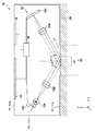
The
筐体11は、例えば、開口部17が形成された第1面11aと、第1面11aの反対側の第2面11bと、側面11cとを有し、第1面11aが被計測面側になるように(第1面11aが被計測面に対向するように)被計測面上に載置される。筐体内には、検出部12、撮像部13および制御部16が設けられ、筐体11の第2面11bには、表示部14(ディスプレイ14a)および操作部15(ボタン群)が設けられる。表示部14と操作部15とは、筐体上(第2面11b)において互いに隣接して設けられていることが操作性の点で好ましい。また、筐体11の側面11cには、ユーザの指を引っ掛けて握り易くするための凹部11d(把持部)が形成されている。ここで、凹部11d(把持部)および操作部15は、ユーザが筐体11の側面11c(凹部11d)を把持しながら操作部15(ボタン群)を操作することができるように筐体11に設けられる(配置される)とよい。このように配置された凹部11dおよび操作部15は、筐体上において互いに隣接して設けられていると言える。
The
検出部12は、筐体11の開口部17が位置する被計測面20の領域のうち第1部分領域21(後述する撮像部13により撮像される被計測面20の領域の一部)に光を照射して、第1部分領域21で反射された光を検出する。検出部12は、例えば、第1部分領域21に光を照射する照射部と、第1部分領域21で反射された光を受光する受光部とを含みうる。照射部は、光源12aとレンズ12bとを含み、第1部分領域21に光を照射する。光源12aは、光源制御回路12cに接続されており、制御部16から光源制御回路12cに送られてきた信号に応じて発光強度が調整される。そして、光源12aから射出された光は、レンズ12bにより平行光に(コリメート)されて第1部分領域21に入射する。また、受光部は、センサ12dとレンズ12eとを含み、第1部分領域21で反射された光を受光する(検出する)。センサ12dは、例えば、CCDやCMOSなどで構成された光電変換素子が2次元的に配列されたエリアセンサを含み、第1部分領域21で反射されてレンズ12eにより集光された光を受光して、第1部分領域21からの反射光の強度分布を検出する。これにより、制御部16(処理部)は、センサ12dから出力された反射光の強度分布データ(検出部12での検出結果)に基づいて、第1部分領域21の反射特性を求めることができる。
The
制御部16(処理部)により求められた第1部分領域21の反射特性を示す値(規格値)は、表示部14によって表示される。表示部14は、例えば、筐体11の第2面11bに設けられたLCDなどのディスプレイ14aを含み、第1部分領域21の反射特性を示す値を当該ディスプレイ14aに表示する。これにより、ユーザは、第1部分領域21の反射特性を視認することができる。また、計測装置10の動作条件などの各種設定は、ユーザが操作部15を操作することによって行われる。操作部15は、筐体11の第2面11bに設けられた複数のボタンを含む。例えば、制御部16は、ユーザによって操作部15の複数のボタンのうちボタン15aが押されたことで生成される信号(操作部15により入力された信号)を検知することにより、被計測面20の反射特性の計測を開始する。本実施形態の操作部15は、複数のボタンを有するが、それに限られず、例えば、表示部14のディスプレイ14aをタッチパネル式とし、当該ディスプレイ14aを操作部15として用いてもよい。
A value (standard value) indicating the reflection characteristic of the first
ここで、被計測面20の反射特性を計測する際に被計測面20に入射させる光の入射角θ(被計測面20で反射される光の反射角θ’)は、JISやISOなどに従って、反射特性の規格ごとに規定される。例えば、反射特性として鏡面光沢度を計測する場合では、入射角θ(反射角θ’)は、20度、45度、60度、75度および85度のいずれかに規定される。また、反射特性としてヘイズを計測する場合では、入射角θ(反射角θ’)は、20度および30度のいずれかに規定される。反射特性として写像性を計測する場合では、入射角θ(反射角θ’)は、45度および60度のいずれかに規定される。反射特性としてDOIを計測する場合では、入射角θ(反射角θ’)は、20度および30度のいずれかに規定される。
Here, the incident angle θ of the light incident on the measured
本実施形態の計測装置10(図2に示す例)では、1つの検出部12が設けられており、1種類の入射角θ(反射角θ’)において被計測面20の反射特性を計測している。しかしながら、前述のように入射角θ(反射角θ’)は反射特性の規格ごとに規定される。そのため、複数種類の入射角θ(反射角θ’)で被計測面20の反射特性を計測することができるように、入射角θ(反射角θ’)が互いに異なる複数の検出部12を計測装置10に設けてもよい。例えば、入射角θ(反射角θ’)が20度となる検出部12と、入射角θ(反射角θ’)が60度となる検出部12とを計測装置10に設けると、鏡面光沢度、ヘイズ、写像性およびDOIの全てを計測することが可能となる。また、複数の検出部12を設けることに限られず、1つの検出部12における入射角θ(反射角θ’)を変更することができるように当該検出部12を駆動する駆動部を計測装置10に設けてもよい。
In the measuring device 10 (example shown in FIG. 2) of the present embodiment, one
このように、反射特性の計測は、筐体11によって外光を遮断した状態で行われるため、反射特性を計測している計測領域(検出部12により反射光を検出する第1部分領域21)を視認することができない。したがって、従来の計測装置では、反射特性を計測すべき対象領域に計測領域が配置されるように計測装置を正確に位置決めすること(対象領域と計測装置との相対的な位置決め)が困難であった。そこで、本実施形態の計測装置10は、筐体11の開口部17を介して被計測面20を撮像する撮像部13を有する。具体的には、撮像部13は、筐体11の開口部17が位置する被計測面20の領域のうち第1部分領域21を含む第2部分領域22を撮像する。そして、撮像部13により得られた第2部分領域22の画像を表示部14(ディスプレイ14a)に表示する。また、表示部14に表示される第2部分領域22の画像は、第2部分領域22における第1部分領域21(の位置)を示す情報を有する。これにより、ユーザは、計測領域だけでなく、その周辺も表示部14で視認することができるため、対象領域に計測領域が配置されるように計測装置10を容易に且つ正確に位置決めすることができる。ここで、第2部分領域22は、第1部分領域21を含み且つ第1部分領域21より大きい(面積が大きい)領域であり、開口部17より小さくてもよいし、開口部17と同じ大きさであってもよい。また、以下では、第2部分領域22における第1部分領域21の位置を示す情報を「第1部分領域21の位置情報」と称する。
As described above, since the measurement of the reflection characteristic is performed in a state where the external light is blocked by the
以下に、本実施形態の撮像部13の構成、および本実施形態の計測装置10を用いて被計測面20の反射特性を計測する方法について説明する。
まず、撮像部13の構成について説明する。撮像部13は、図3に示すように、例えば、第2部分領域22に光を照射する光源13aと、光が照射された第2部分領域22を撮像するカメラ13bとを有する。本実施形態では、第2部分領域22に斜めから光を照射し、第2部分領域22を斜めから撮像するように光源13aおよびカメラ13bが配置されている。具体的には、光源13aからの光の主光線を第2部分領域22に入射させる角度(照明角α)が60度となるように光源13aが配置され、第2部分領域22を撮像する角度(撮像角β)が45度となるようにカメラ13bが配置される。つまり、照明角αより撮像角βの方が小さくなるように光源13aおよびカメラ13bが配置される。照明角αおよび撮像角βは任意に設定することができるが、このような光源13aおよびカメラ13bの配置は筐体内の空間が狭いときに有利である。筐体内の空間が広く、筐体11と干渉しないのであれば、第2部分領域22に上方から光を照射し、第2部分領域22を上方から撮像するように光源13aおよびカメラ13bを配置することもできる。
Hereinafter, the configuration of the
First, the configuration of the
光源13aは、第2部分領域22に光を照射する(第2部分領域22を照明する)。光源13aは、光源制御回路13cに接続されており、制御部16から光源制御回路13cに送られてきた信号に応じて発光強度が調整されうる。光源13aとしては、カメラ13bの画角、および開口部17に対するカメラ13bの配置に応じて決定される第2部分領域22の全体に光が照射されるように、角度γ以上の指向特性を有する光源(例えばLEDなど)が用いられることが好ましい。本実施形態の光源13aは、検出部12が第1部分領域21に光を照射する方向(方位)に対して垂直な方向から第2部分領域22に光を照射するように構成されているが、第2部分領域22に光を照射する方向は任意に設定することができる。
The
また、カメラ13bは、例えばCCDカメラやCMOSカメラなどによって構成され、光源13aによって照明された第2部分領域22を撮像し、それにより得られた第2部分領域22の画像データ(映像データ)を出力する。そして、撮像部13で得られた画像(映像)は、表示部14(ディスプレイ14a)に表示される。
Further, the
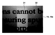
表示部14に表示される第2部分領域22の画像は、前述のように、第1部分領域21の位置情報を有する。第1部分領域21の位置情報を有する第2部分領域22の画像を生成する1つの方法としては、例えば、検出部12により第1部分領域21に光を照射しながら、撮像部13により第2部分領域22に光を照射して当該第2部分領域22を撮像する方法がある。この方法では、第2部分領域22における第1部分領域21以外の領域に撮像部13からの光のみが照射され、第1部分領域21に撮像部13からの光と検出部12からの光との双方が照射される。そのため、撮像部13で得られて表示部14に表示される第2部分領域22の画像では、図4に示すように、第1部分領域21に対応する部分31の明度が、それ以外(周辺)の部分32の明度より大きくなる。つまり、第1部分領域21に対応する部分31とそれ以外の部分32との明度の差を、第1部分領域21の位置情報として生成することができる。
The image of the second
図4は、表示部14に表示された第2部分領域22の画像を示す図である。本実施形態では、撮像部13によって第2部分領域22を斜めから撮像しているため、表示部14に表示される第2部分領域22の画像が台形形状となる。また、図4に示す第2部分領域22の画像では、第1部分領域21に対応する部分31の明度が部分31の周辺の部分32より大きいため、当該画像における第1部分領域(計測領域)の位置を視認することができる。ここで、撮像部13により第2部分領域22に照射される光の強度は、検出部12により第1部分領域21に照射される光の強度より小さくするとよい。これにより、表示部14で表示される第2部分領域22の画像において部分31と部分32との明度の差を大きくし、当該画像における第1部分領域21の位置を更に視認しやすくすることができる。
FIG. 4 is a diagram showing an image of the second
次に、計測装置10を用いて被計測面20の反射特性を計測する方法について、図5を参照しながら説明する。図5は、被計測面20の反射特性を計測する方法を示すフローチャートである。図5に示すフローチャートの各工程は、制御部16によって制御されうる。
Next, a method of measuring the reflection characteristics of the surface to be measured 20 using the measuring
S11では、制御部16は、検出部12からの光を第1部分領域21に照射し、且つ撮像部からの光を第2部分領域22に照射している状態で、第2部分領域22を撮像部13に撮像させる。そして、撮像部13により得られた第2部分領域22の画像(映像)を表示部14に表示する。S12では、制御部16は、ユーザからの信号を検知したか否かを判断する。制御部16がユーザからの信号を検知していない場合にはS11に戻り、ユーザからの信号を検知した場合にはS13に進む。
In S11, the
S11およびS12の工程では、ユーザが、表示部14に表示された画像に基づいて、反射特性を計測すべき被計測面20の対象領域に計測装置10の計測領域(第1部分領域21)が配置されるように計測装置10の位置決めを行っている状態である。ユーザは、例えば、計測装置10の位置決めを終了すると、反射特性の計測を計測装置10に開始させるために操作部15のセンサを操作する(本実施形態ではボタン15aを押す)。このとき、計測装置10では、センサ(ボタン15a)からの出力が制御部16に送信され、制御部16は、当該出力をユーザからの信号(操作部15により入力された信号)として検知することができる。本実施形態では、センサとしてボタン15aを用いたが、それに限られず、ユーザの手(指)の接触を感知するための温度センサや光センサなどが用いられてもよい。また、本実施形態では、ユーザがセンサに触れたとき(ユーザがボタン15aを押したとき)のセンサの出力をユーザからの信号として用いた。しかしながら、それに限られず、例えば、ユーザがセンサから手を離したとき(押していたボタン15aを離したとき)のセンサの出力をユーザからの信号として用いてもよい。
In the steps S11 and S12, the measurement area (first partial area 21) of the measuring
S13では、制御部16は、ユーザによってセンサ(ボタン15a)が操作されたとき(ユーザからの信号を検知したとき)に撮像部13で撮像されて表示部14に表示された第2部分領域22の画像をメモリ(記憶部)に記憶する。S14では、制御部16は、検出部12からの光以外の光が検出部12のセンサに入射することを防ぐため、撮像部13による第2部分領域22への光の照射を終了(中断)し、検出部12からの光のみを第1部分領域21に照射する。そして、制御部16は、第1部分領域21で反射された光を検出部12(センサ12d)に検出させる。図6は、検出部12からの光のみを第1部分領域21に照射している状態において撮像部13により得られた第2部分領域22の画像を示す図である。このように得られた第2部分領域22の画像は、表示部14に表示させてもよいし、表示させなくてもよい。ここで、計測装置10に複数の検出部12が設けられている場合には、制御部16は、第1部分領域21に光を照射して第1部分領域21で反射した光を検出する工程を、各検出部12に順番に行わせる。
In S13, the
S15では、制御部16は、検出部12での検出結果(センサ12dから出力された反射光の強度分布データ)に基づいて第1部分領域21の反射特性を求める。このとき、制御部16は、求めた反射特性を、S13においてメモリに記憶された第2部分領域22の画像と対応付けてメモリに記憶する。これにより、ユーザは、メモリに記憶された反射特性が被計測面上のどこの領域の反射特性なのかを容易に把握することができる。S16では、制御部16は、S15で求めた反射特性を示す値を表示部14に表示する。このとき、制御部16は、S13においてメモリに記憶された第2部分領域22の画像と反射特性を示す値とを重ねて表示部14に表示してもよいし、反射特性を示す値のみを表示部14に表示してもよい。後者の場合、制御部16は、ユーザからの信号を検知する前には、第2部分領域22の画像を表示部14に表示させ、ユーザからの信号を検知した後では、反射特性を示す値を表示部14に表示させる。つまり、制御部16は、ユーザからの信号に応じて、第2部分領域22の画像と反射特性を示す値とを切り替えて(即ち、選択的に)表示部14に表示させる。
In S15, the
このような工程により1回の反射特性の計測が終了するが、制御部16は、所定の時間(例えば3秒間など)が経過した後、S11に戻り、撮像部13によって得られた第2部分領域22の画像(映像)を表示部14に表示させる。これにより、ユーザは、被計測面20の反射特性の計測を引き続き行うことができる。
Although one measurement of the reflection characteristic is completed by such a step, the
上述したように、本実施形態の計測装置10は、開口部17が位置する被計測面20の領域のうち、反射特性の計測が行われる第1部分領域21を含む第2部分領域22を撮像し、それにより得られた第2部分領域22の画像を表示部14に表示する。また、表示部14に表示される第2部分領域22の画像は、第1部分領域21の位置情報を有する。これにより、ユーザは、表示部14によって計測領域を容易に視認することができるため、反射特性を計測すべき被計測面20の対象領域に第1部分領域21(計測領域)が配置されるように計測装置10を容易に位置決めすることができる。
As described above, the measuring
ここで、本実施形態の計測装置10は、操作部15のボタン15aからの出力をユーザからの信号として検知したことに応じて、反射特性の計測を開始したが、それに限られるものではない。例えば、筐体11の外部に配置された装置(例えば情報処理装置)からケーブルや無線などを介して送られてきた(受信した)ユーザからの信号を検知したことに応じて、反射特性の計測を開始してもよい。この場合、制御部16は、当該装置の入力部(キーボードやマウスなど)により入力された信号を、ユーザからの信号として検知する。また、本実施形態の計測装置10は、第2部分領域22の画像と反射特性を示す値とを対応付けて制御部16(メモリ)に記憶したが、それに限られるものではない。例えば、筐体11の外部に配置された装置に、ケーブルや無線を介して、第2部分領域の画像と反射特性の値とを対応付けて送信し、当該装置に記憶してもよい。このように筐体11の外部に配置された装置は、計測装置10における構成要素の1つとしてもよい。
Here, the measuring
さらに、本実施形態では、撮像部13で得られた第2部分領域22の画像を表示する表示部14として、筐体11に設けられたディスプレイ14aを用いたが、それに限られず、例えば筐体11の外部に設けられた外部ディスプレイを表示部として用いてもよい。この場合には、制御部16は、撮像部13で得られた第2部分領域22の画像データを、ケーブルや無線を介して外部ディスプレイに送信し、当該外部ディスプレイに表示する。このように筐体11の外部に設けられた外部ディスプレイは、計測装置10における構成要素の1つとしてもよい。
Further, in the present embodiment, the display 14a provided in the
<第2実施形態>
本発明に係る第2実施形態の計測装置について説明する。第1実施形態の計測装置10では、撮像部13によって第2部分領域22を斜めから撮像し、それによって得られた画像をそのまま表示部14に表示しているため、図4に示すように、表示部14に表示される第2部分領域22の画像が台形形状となる。本実施形態では、撮像部13によって第2部分領域22を斜めから撮像することで得られた台形形状の画像に対して幾何学的な画像変換を行い、画像変換が行われた画像を表示部14に表示する例について説明する。それ以外の構成は第1実施形態と同様であるため、ここでは説明を省略する。
<Second Embodiment>
The measuring device of the second embodiment according to the present invention will be described. In the measuring
以下に、撮像部13により45度の撮像角βで第2部分領域22を撮像することで得られた画像を、あたかも0度の撮像角βで第2部分領域22を撮像したような画像(例えば矩形形状の画像)に変換する画像変換方法について説明する。画像変換は、制御部16(処理部)によって行われうる。
The following is an image obtained by imaging the second
制御部16は、撮像部13で得られた画像データに射影変換を適用して座標変換を行う。射影変換とは、歪んだ四角形の画像を矩形形状(正方形または長方形)の画像に補正する際に適用される座標変換のうちの1つである。画像データにおいて、変換前の座標を(x,y)とし、変換後の座標を(x’,y’)とすると、変換後の座標を式(1)によって求めることができる。ここで、h11〜h33は、変換前の4点の座標と変換後の4点の座標から求められる変換係数である。
The

次に、制御部16は、射影変換によって座標変換が行われた画像の画素補間を行う。画像を幾何学的に変換する場合、画素と画素との間の輝度値を参照する画像フィルタ処理を行って隙間に相当する画素のデータを補う、いわゆる画素補間を行う必要がある。ここでは、制御部16において射影変換が行われた画像データに対し、さらに双一次補間を適用して画素補間を行う。双一次補間は、補うべき画素の座標(x’,y’)の周辺の2×2画素(4画素)を用いて直線的に補間し、輝度値を求める線形補間のうちの1つである。
Next, the
このように、撮像部13で得られた第2部分領域22の画像に対して幾何学的な画像変換(射影変換を用いた座標変換、および双一次補間を用いた画素補間)を行う。これにより、図4に示すような台形形状の画像を、図7に示すような矩形形状の画像に変換して表示部14に表示することができる。図7は、撮像部13で得られた第2部分領域22の画像に対して幾何学的な画像変換を行った後に、表示部14に表示された第2部分領域22の画像を示す図である。
In this way, geometrical image transformation (coordinate transformation using projective transformation and pixel interpolation using bilinear interpolation) is performed on the image of the second
ここで、本実施形態では、幾何学的な画像変換における座標変換として射影変換を用いたが、それに限られるものではない。例えば、平行移動と線形変換とにより座標変換を行う場合には、アフィン変換などを用いることができる。また、本実施形態では画素補間として双一次補間を用いたが、最近傍補間などを用いることもできる。最近傍補間は、補間する画素の位置に最も近い位置にある画素の輝度値を参照する方法であり、補間される画素のデータは双一次補間とは異なる輝度値になるものの、双一次補間と同様に画素補間を行うことができる。さらに、本実施形態では、撮像部13により45度の撮像角βで第2部分領域22を撮像することで得られた画像に対して幾何学的な画像変換を行う例について説明した。しかしながら、それに限られず、45度以外の撮像角βでの撮像により得られた画像についても、前述した幾何学的な画像変換を行うことで、図7に示す画像と同様の画像を得ることができる。
Here, in the present embodiment, the projection transformation is used as the coordinate transformation in the geometric image transformation, but the present invention is not limited to this. For example, when performing coordinate transformation by translation and linear transformation, affine transformation or the like can be used. Further, in the present embodiment, bilinear interpolation is used as pixel interpolation, but nearest neighbor interpolation and the like can also be used. Nearest-neighbor interpolation is a method of referring to the brightness value of the pixel closest to the position of the pixel to be interpolated. Pixel interpolation can be performed in the same manner. Further, in the present embodiment, an example in which the image obtained by imaging the second
上述したように、本実施形態では、撮像部13で得られた第2部分領域22の画像に対して幾何学的な画像変換を行い、それにより得られた画像を表示部14に表示する。これにより、ユーザによる計測領域(第1部分領域21)の視認性をさらに向上させることができる。
As described above, in the present embodiment, the image of the second
<第3実施形態>
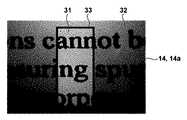
本発明に係る第3実施形態の計測装置について説明する。第1実施形態では、第1部分領域21の位置情報を有する第2部分領域22の画像を生成する1つの方法として、検出部12により第1部分領域21に光を照射しながら第2部分領域22を撮像する方法を説明した。本実施形態では、図8に示すように、第1部分領域21の位置を示すマーク33を、撮像部13で得られた第2部分領域22の画像に重ねて表示することにより、第1部分領域21の位置情報を有する第2部分領域22の画像を生成する方法を説明する。それ以外の構成は第1実施形態と同様であるため、ここでは説明を省略する。
<Third Embodiment>
The measuring device of the third embodiment according to the present invention will be described. In the first embodiment, as one method of generating an image of the second
まず、第1部分領域21の位置を示すマーク33を表示する方法の1つの例について説明する。第2部分領域22における第1部分領域21の位置は、反射特性を計測すべき対象領域を変更したとしても通常変わらない。そのため、第1部分領域21が表示されるべき表示部14上の位置を事前に求めておき、撮像部13で得られた第2部分領域22の画像を表示部14に表示するとともに、事前に求めた表示部14上の位置にマーク33を重ねて表示してもよい。この場合、撮像部13は、検出部12により第1部分領域21に光を照射しながら第2部分領域22を撮像しなくてもよい。即ち、撮像部13は、検出部12による第1部分領域21への光の照射を行わずに、撮像部13による第2部分領域22への光の照射のみを行って第2部分領域22を撮像してもよい。
First, one example of a method of displaying the
ここで、第1部分領域21の位置を示すマーク33は、例えば、第1部分領域21の外形(輪郭)を示すマークを含むが、例えば、第1部分領域21の四隅を示すマークなど他のマークを含んでもよい。また、第1部分領域21の位置を示すマークを用いずに、例えば、第1部分領域21の輝度値を周辺より大きくしたり、小さくしたりするなど、第1部分領域21の位置を強調した手法を用いてもよい。以下の例についても同様である。
Here, the
次に、第1部分領域21の位置を示すマーク33を表示する方法の他の例について説明する。ここでは、検出部12により第1部分領域21に光を照射しながら第2部分領域22を撮像することにより得られた画像から、第2部分領域22における第1部分領域21の位置を求め、当該位置を示すマーク33を表示部14に表示する例を説明する。以下では、第1部分領域21の位置として、第1部分領域21の外形(輪郭)を制御部16によって求める方法を説明する。
Next, another example of the method of displaying the
制御部16は、撮像部13で得られた画像データに輪郭抽出を適用して第1部分領域21の抽出を行う。輪郭抽出とは、画像データにおける画素の輝度勾配を算出した結果に基づいて、画素の輝度が不連続に変化している箇所を抽出する際に適用される画像処理のうちの1つである。ここでは、画像データにおける画素のX方向とY方向の隣接画素同士の差分をとることにより1次微分を行って輪郭を抽出する方法について述べるが、輪郭抽出には様々な方法がある。例えば、輪郭抽出の対象画素に対して上下左右の4方向に2次微分を行うことにより、方向性に依存しない輪郭抽出を行うこともできる。
The
画像データにおいて、座標(x,y)の画素を輪郭抽出の対象画素とし、その画素の輝度値がf(x,y)で得られるとすると、X方向の微分値fxとY方向の微分値fyを式(2)によって求めることができる。また、式(2)によって得られた微分値fx、fyから、式(3)を用いて座標(x,y)における輪郭の強さIを算出することができる。これにより、制御部16は、式(3)によって算出された輪郭の強さIを用いて第1部分領域21を抽出することができ、抽出した第1部分領域21の位置を示すマーク33を表示部14に表示させることができる。
In the image data, assuming that the pixel of the coordinates (x, y) is the target pixel for contour extraction and the brightness value of the pixel is obtained by f (x, y), the differential value fx in the X direction and the differential value in the Y direction. The fy can be obtained by the equation (2). Further, from the differential values fx and fy obtained by the equation (2), the contour strength I at the coordinates (x, y) can be calculated using the equation (3). As a result, the
上述したように、本実施形態では、第2部分領域22における第1部分領域21の位置を示すマーク33を、撮像部13で得られた第2部分領域22の画像に重ねて表示部14に表示する。これにより、ユーザによる計測領域(第1部分領域21)の視認性をさらに向上させることができる。
As described above, in the present embodiment, the
以上、本発明の好ましい実施形態について説明したが、本発明はこれらの実施形態に限定されないことはいうまでもなく、その要旨の範囲内で種々の変形および変更が可能である。 Although the preferred embodiments of the present invention have been described above, it goes without saying that the present invention is not limited to these embodiments, and various modifications and modifications can be made within the scope of the gist thereof.
10:計測装置、11:筐体、12:検出部、13:撮像部、14:表示部、15:操作部、16:制御部(処理部)、20:被計測面、21:第1部分領域、22:第2部分領域 10: Measuring device, 11: Housing, 12: Detection unit, 13: Imaging unit, 14: Display unit, 15: Operation unit, 16: Control unit (processing unit), 20: Measured surface, 21: First part Region, 22: Second subregion
Claims (17)
前記筐体内に設けられ、前記面の撮像領域を照射して前記開口部を介して前記撮像領域を撮像する撮像部と、
前記筐体内に設けられ、前記撮像領域の一部である計測領域を照射して前記計測領域からの反射光を前記開口部を介して検出する検出部と、
前記検出部による検出結果に基づいて前記計測領域の反射特性を得る処理部と、
を含み、
前記処理部は、前記撮像領域における前記計測領域の位置を示す情報を含む前記撮像領域の画像を表示部に出力し、
前記検出部により前記計測領域に光を照射しながら前記撮像部により前記撮像領域に光を照射することで、前記計測領域以外の前記撮像領域の光強度が前記計測領域の光強度より小さい状態を生成し、当該状態で前記撮像部が前記撮像領域を撮像することにより、前記情報を含む前記撮像領域の画像を得る、ことを特徴とする計測装置。 A measuring device having a housing in which an opening is formed and measuring the reflection characteristics of a surface through the opening in a state where the measurement area is covered by the housing.
The housing provided in the body, an imaging unit for imaging the imaging area through the opening by irradiating an imaging area of said surface,
A detection unit provided in the housing, which irradiates a measurement area that is a part of the imaging area and detects reflected light from the measurement area through the opening.
A processing unit that obtains the reflection characteristics of the measurement region based on the detection result by the detection unit, and
Including
The processing unit outputs an image of the imaging region including information indicating the position of the measurement region in the imaging region to the display unit.
By irradiating the measurement region with light by the detection unit and irradiating the imaging region with light by the imaging unit, the light intensity of the imaging region other than the measurement region is smaller than the light intensity of the measurement region. A measuring device characterized in that an image of the imaging region including the information is obtained by generating and imaging the imaging region in the state.
前記処理部は、前記入力部により入力された信号に応じて前記検出部に前記反射光を検出させ、前記検出部で検出された前記反射光に基づいて前記反射特性を得る、ことを特徴とする請求項1又は2に記載の計測装置。 Including the input part operated by the user
The processing unit is characterized in that the detection unit detects the reflected light in response to a signal input by the input unit and obtains the reflection characteristic based on the reflected light detected by the detection unit. The measuring device according to claim 1 or 2.
前記処理部は、前記入力部により入力された信号に基づいて、前記反射特性と、前記撮像部により得られた前記撮像領域の画像とを選択的に前記表示部に表示させる、ことを特徴とする請求項1乃至3のうちいずれか1項に記載の計測装置。 Including the input part operated by the user
The processing unit is characterized in that the reflection characteristic and the image of the imaging region obtained by the imaging unit are selectively displayed on the display unit based on the signal input by the input unit. The measuring device according to any one of claims 1 to 3.
前記撮像部は、前記検出部により前記計測領域に光が照射されている状態で、前記撮像領域に光を照射しながら前記撮像領域を撮像することにより、前記情報を含む前記撮像領域の画像を得る、ことを特徴とする請求項1乃至5のうちいずれか1項に記載の計測装置。 The detection unit irradiates the measurement area with light and detects the reflected light from the measurement area.
In a state where the measurement region is irradiated with light by the detection unit, the imaging unit captures the imaging region while irradiating the imaging region with light to obtain an image of the imaging region including the information. The measuring device according to any one of claims 1 to 5 , wherein the measuring device is obtained.
前記表示部と前記入力部とは、前記筐体上において互いに隣接して設けられている、ことを特徴とする請求項1乃至8のうちいずれか1項に記載の計測装置。 The display unit and the input unit operated by the user are included.
The measuring device according to any one of claims 1 to 8 , wherein the display unit and the input unit are provided adjacent to each other on the housing.
ユーザにより把持される把持部と、を含み、
前記入力部と前記把持部とは、前記筐体上において互いに隣接して設けられている、ことを特徴とする請求項1乃至9のうちいずれか1項に記載の計測装置。 The input section operated by the user and
Including a grip portion gripped by the user,
The measuring device according to any one of claims 1 to 9 , wherein the input portion and the grip portion are provided adjacent to each other on the housing.
前記検出部は、前記開口部を介して、前記計測領域に光を照射しながら前記計測領域からの前記反射光を検出する、ことを特徴とする請求項1乃至11のうちいずれか1項に記載の計測装置。 The imaging unit captures the imaging region while irradiating the imaging region with light through the opening.
The invention according to any one of claims 1 to 11 , wherein the detection unit detects the reflected light from the measurement area while irradiating the measurement area with light through the opening. The measuring device described.
Priority Applications (3)
| Application Number | Priority Date | Filing Date | Title |
|---|---|---|---|
| JP2016207260A JP6869002B2 (en) | 2016-10-21 | 2016-10-21 | Measuring device |
| EP17195391.2A EP3312591B1 (en) | 2016-10-21 | 2017-10-09 | Measuring apparatus |
| US15/785,753 US10634611B2 (en) | 2016-10-21 | 2017-10-17 | Measuring apparatus |
Applications Claiming Priority (1)
| Application Number | Priority Date | Filing Date | Title |
|---|---|---|---|
| JP2016207260A JP6869002B2 (en) | 2016-10-21 | 2016-10-21 | Measuring device |
Publications (3)
| Publication Number | Publication Date |
|---|---|
| JP2018066712A JP2018066712A (en) | 2018-04-26 |
| JP2018066712A5 JP2018066712A5 (en) | 2019-11-28 |
| JP6869002B2 true JP6869002B2 (en) | 2021-05-12 |
Family
ID=60051400
Family Applications (1)
| Application Number | Title | Priority Date | Filing Date |
|---|---|---|---|
| JP2016207260A Active JP6869002B2 (en) | 2016-10-21 | 2016-10-21 | Measuring device |
Country Status (3)
| Country | Link |
|---|---|
| US (1) | US10634611B2 (en) |
| EP (1) | EP3312591B1 (en) |
| JP (1) | JP6869002B2 (en) |
Families Citing this family (7)
| Publication number | Priority date | Publication date | Assignee | Title |
|---|---|---|---|---|
| JP6481188B1 (en) * | 2018-06-20 | 2019-03-13 | スガ試験機株式会社 | Image clarity measuring instrument |
| US11195030B2 (en) | 2018-09-14 | 2021-12-07 | Honda Motor Co., Ltd. | Scene classification |
| US11034357B2 (en) | 2018-09-14 | 2021-06-15 | Honda Motor Co., Ltd. | Scene classification prediction |
| USD978685S1 (en) * | 2020-02-14 | 2023-02-21 | Proceq Ag | Housing for glossmeter |
| USD962803S1 (en) * | 2020-03-13 | 2022-09-06 | Purdue Research Foundation | Food allergen detector |
| JP2022187663A (en) | 2021-06-08 | 2022-12-20 | 富士フイルムビジネスイノベーション株式会社 | Surface inspection device and program |
| JP2023045476A (en) * | 2021-09-22 | 2023-04-03 | 富士フイルムビジネスイノベーション株式会社 | Surface inspection device and program |
Family Cites Families (17)
| Publication number | Priority date | Publication date | Assignee | Title |
|---|---|---|---|---|
| US5155558A (en) * | 1990-09-19 | 1992-10-13 | E. I. Du Pont De Nemours And Company | Method and apparatus for analyzing the appearance features of a surface |
| JPH0771945A (en) * | 1992-08-07 | 1995-03-17 | Kao Corp | Surface texture measuring method and apparatus |
| JPH09178564A (en) * | 1995-12-21 | 1997-07-11 | Shimadzu Corp | Spectrometer |
| DE69631475T2 (en) * | 1996-07-16 | 2005-01-13 | Perkin-Elmer Ltd., Beaconsfield | Control of a microscope screen |
| JP2001341288A (en) * | 2000-05-30 | 2001-12-11 | Dainippon Printing Co Ltd | Method and apparatus for color measurement of printed matter |
| US6826424B1 (en) * | 2000-12-19 | 2004-11-30 | Haishan Zeng | Methods and apparatus for fluorescence and reflectance imaging and spectroscopy and for contemporaneous measurements of electromagnetic radiation with multiple measuring devices |
| JP3470268B2 (en) * | 2001-07-17 | 2003-11-25 | 川崎重工業株式会社 | Target extraction method |
| DE102004034160A1 (en) * | 2004-07-15 | 2006-02-09 | Byk Gardner Gmbh | Device for studying optical surface properties |
| JP4797593B2 (en) * | 2005-03-10 | 2011-10-19 | 富士ゼロックス株式会社 | Gloss measuring apparatus and program |
| JP2008151781A (en) * | 2007-12-03 | 2008-07-03 | Olympus Corp | Device and method for image display |
| JP5638234B2 (en) * | 2009-12-22 | 2014-12-10 | ショットモリテックス株式会社 | Transparency measuring device and transparency measuring method |
| JP5738005B2 (en) * | 2011-03-01 | 2015-06-17 | 株式会社トプコン | Lightwave distance measuring device |
| JP5989443B2 (en) * | 2012-07-31 | 2016-09-07 | 公立大学法人公立はこだて未来大学 | Semiconductor integrated circuit and object distance measuring device |
| JP6049215B2 (en) * | 2014-01-16 | 2016-12-21 | 富士フイルム株式会社 | Photoacoustic measurement apparatus, signal processing apparatus and signal processing method used therefor |
| JP6324114B2 (en) * | 2014-02-28 | 2018-05-16 | キヤノン株式会社 | Optical system and gloss meter |
| JP6099023B2 (en) * | 2014-05-29 | 2017-03-22 | パナソニックIpマネジメント株式会社 | Projector system |
| WO2018016572A1 (en) * | 2016-07-22 | 2018-01-25 | シャープ株式会社 | Display correction apparatus, program, and display correction system |
-
2016
- 2016-10-21 JP JP2016207260A patent/JP6869002B2/en active Active
-
2017
- 2017-10-09 EP EP17195391.2A patent/EP3312591B1/en not_active Not-in-force
- 2017-10-17 US US15/785,753 patent/US10634611B2/en active Active
Also Published As
| Publication number | Publication date |
|---|---|
| US10634611B2 (en) | 2020-04-28 |
| EP3312591B1 (en) | 2020-12-16 |
| US20180113073A1 (en) | 2018-04-26 |
| EP3312591A1 (en) | 2018-04-25 |
| JP2018066712A (en) | 2018-04-26 |
Similar Documents
| Publication | Publication Date | Title |
|---|---|---|
| JP6869002B2 (en) | Measuring device | |
| JP3951984B2 (en) | Image projection method and image projection apparatus | |
| US7924312B2 (en) | Infrared and visible-light image registration | |
| CN102142143B (en) | Infrared image compares | |
| JP5740822B2 (en) | Information processing apparatus, information processing method, and program | |
| JP2008269616A (en) | Cursor control device and method for image display, and image system | |
| TW201104508A (en) | Stereoscopic form reader | |
| KR20070013512A (en) | Image processing apparatus and method | |
| CN112739976A (en) | Dimension measuring device and dimension measuring method | |
| JP6241052B2 (en) | Image processing system and image processing program | |
| JP5522630B2 (en) | 3D system | |
| CN111868734A (en) | Contactless Rolling Fingerprint | |
| CN101452349B (en) | Cursor control device, method and image system on image display device | |
| US20210174540A1 (en) | Image recognition apparatus using an object image data, image recognition method using an object image data, and program | |
| JP7419846B2 (en) | Liquid level detection method and liquid level detection device | |
| US20190323958A1 (en) | Measurement apparatus, information processing apparatus, information processing method, and storage medium | |
| JP2011191170A (en) | Image processing apparatus | |
| JP2011188023A (en) | Information processing unit, method of processing information, and program | |
| US10116809B2 (en) | Image processing apparatus, control method, and computer-readable storage medium, which obtains calibration image information with which to correct image data | |
| JP6412372B2 (en) | Information processing apparatus, information processing system, information processing apparatus control method, and program | |
| JP5004099B2 (en) | Cursor movement control method and cursor movement control apparatus | |
| JP2020129187A (en) | Outline recognition device, outline recognition system, and outline recognition method | |
| JP7517006B2 (en) | Inspection equipment and inspection program | |
| WO2005096130A1 (en) | Method and device for detecting directed position of image pickup device and program for detecting directed position of image pickup device | |
| JP2019016843A (en) | Document reading device, control method of document reading device, and program |
Legal Events
| Date | Code | Title | Description |
|---|---|---|---|
| A521 | Written amendment |
Free format text: JAPANESE INTERMEDIATE CODE: A523 Effective date: 20191011 |
|
| A621 | Written request for application examination |
Free format text: JAPANESE INTERMEDIATE CODE: A621 Effective date: 20191011 |
|
| A977 | Report on retrieval |
Free format text: JAPANESE INTERMEDIATE CODE: A971007 Effective date: 20200415 |
|
| A131 | Notification of reasons for refusal |
Free format text: JAPANESE INTERMEDIATE CODE: A131 Effective date: 20200518 |
|
| A521 | Written amendment |
Free format text: JAPANESE INTERMEDIATE CODE: A523 Effective date: 20200706 |
|
| A131 | Notification of reasons for refusal |
Free format text: JAPANESE INTERMEDIATE CODE: A131 Effective date: 20201120 |
|
| RD01 | Notification of change of attorney |
Free format text: JAPANESE INTERMEDIATE CODE: A7421 Effective date: 20210103 |
|
| A521 | Written amendment |
Free format text: JAPANESE INTERMEDIATE CODE: A523 Effective date: 20210113 |
|
| A521 | Written amendment |
Free format text: JAPANESE INTERMEDIATE CODE: A523 Effective date: 20210118 |
|
| TRDD | Decision of grant or rejection written | ||
| A01 | Written decision to grant a patent or to grant a registration (utility model) |
Free format text: JAPANESE INTERMEDIATE CODE: A01 Effective date: 20210315 |
|
| A61 | First payment of annual fees (during grant procedure) |
Free format text: JAPANESE INTERMEDIATE CODE: A61 Effective date: 20210413 |
|
| R151 | Written notification of patent or utility model registration |
Ref document number: 6869002 Country of ref document: JP Free format text: JAPANESE INTERMEDIATE CODE: R151 |