JP6867774B2 - Image coding device and its control method - Google Patents
Image coding device and its control method Download PDFInfo
- Publication number
- JP6867774B2 JP6867774B2 JP2016203813A JP2016203813A JP6867774B2 JP 6867774 B2 JP6867774 B2 JP 6867774B2 JP 2016203813 A JP2016203813 A JP 2016203813A JP 2016203813 A JP2016203813 A JP 2016203813A JP 6867774 B2 JP6867774 B2 JP 6867774B2
- Authority
- JP
- Japan
- Prior art keywords
- image
- ldr image
- ldr
- hdr
- auxiliary data
- Prior art date
- Legal status (The legal status is an assumption and is not a legal conclusion. Google has not performed a legal analysis and makes no representation as to the accuracy of the status listed.)
- Active
Links
Images


Landscapes
- Compression Or Coding Systems Of Tv Signals (AREA)
- Compression Of Band Width Or Redundancy In Fax (AREA)
Description
本発明は画像符号化技術、特に、高ダイナミックレンジ(High Dynamic Range;HDR)を持つデジタル画像(以下、HDR画像)の符号化技術に関するものである。 The present invention relates to an image coding technique, particularly a coding technique for a digital image (hereinafter, HDR image) having a high dynamic range (HDR).
静止画像の流通のためのデータ形式の代表的なものにJPEGがある。JPEGは、デジタルカメラの出力ファイルのデータ形式として利用されていることもあって、それを利用したソフトウェアは、ウェブブラウザを始め、多数存在する。JPEG圧縮の対象となる静止画像は、1コンポーネント当り8ビット(256階調)の画像データである。 JPEG is a typical data format for the distribution of still images. Since JPEG is used as a data format for output files of digital cameras, there are many softwares that use it, including web browsers. The still image to be JPEG-compressed is 8-bit (256 gradations) image data per component.
一方、人間の視覚は1:10000までのコントラスト比を認識できるため、従来のJPEG画像の階調表現では実際の見た目と大きな差ができる。そこで、1コンポーネント当り8ビットを超えるビット数(例えば32ビット)で表されるHDR画像が注目されている。最近のデジタルカメラやスマートフォンでもHDRモードを搭載したものが一般的になっている。また、簡単にコンポーネント当り32ビットのデータを持つHDR画像を作成できるソフトウェアアプリケーションも増えてきている。 On the other hand, since human vision can recognize a contrast ratio of up to 1: 10000, the gradation expression of a conventional JPEG image can make a large difference from the actual appearance. Therefore, an HDR image represented by a number of bits (for example, 32 bits) exceeding 8 bits per component is attracting attention. Even in recent digital cameras and smartphones, those equipped with an HDR mode have become common. In addition, software applications that can easily create HDR images with 32-bit data per component are increasing.
1コンポーネント当り32ビットのデータを持つHDR画像を、従来のJPEGビューアで見ることができる技術が、ISO/IEC 18477−2(JPEG XT Part 2)で規定されている。また、特許文献1にも同様の技術が開示されている。HDR画像を8[ビット/コンポーネント]の、より小さいダイナミックレンジ画像(Low Dynamic Range:LDR画像)にトーンマッピングし、JPEG圧縮する。そして、原画であるHDR画像とLDR画像の比率を別途HDR補助データとして作成し、HDR補助データとLDR画像のJPEG符号データを、1つのファイルに保存するという方法である。HDR補助データを保存する場所は、JPEGのアプリケーションマーカ(APP11)内である。一般的なJPEGビューアは、サポートしないAPPマーカを無視してデコードする。そのため、たとえば、APP11を、HDR補助データを保存しているマーカとして認識できないJPEGビューアがHDR補助データをもつJPEGファイルを受け取ると、LDR画像のみをデコードし表示する。一方、APP11にHDR補助データが保存されていることを認識できるHDR画像ビューアは、LDR画像とAPP11マーカ内のHDR補助データを組み合わせて、元のHDR画像をデコードし表示できる、という仕組みである。
ISO / IEC 18477-2 (JPEG XT Part 2) defines a technique for viewing an HDR image having 32 bits of data per component with a conventional JPEG viewer. Further,
ここで、HDR補助データの作成方法について考察する。まず、ISO/IEC 18477−2に準拠したHDR画像の符号化処理について、図1Aを参照して説明する。なお、それぞれの処理については、ISO/IEC 18477−2に記載されているため、詳細な説明は割愛し、ここでは簡単な説明にとどめる。 Here, a method of creating HDR auxiliary data will be considered. First, the coding process of the HDR image based on ISO / IEC 18477-2 will be described with reference to FIG. 1A. Since each process is described in ISO / IEC 18477-2, detailed description thereof will be omitted, and only a brief description will be given here.
まず、LDR画像のJPEG符号データの作成までを説明する。入力としてHDR画像101が与えられると、HDR画像101はトーンマッピング部102により、1コンポーネントあたり0−255の256階調の線形色空間のLDR画像に変換される。色変換部112は、線形色空間の線形LDR画像を、sRGB色空間に変換する。そして、sRGB空間の画像データは、RGB/YCC変換部113およびサブサンプリング部114による処理を経て、JPEG圧縮部115に供給され、JPEG符号化される。
First, up to the creation of JPEG code data of the LDR image will be described. When the
次に、HDR補助データの作成の手順を説明する。Y算出部103は、HDR画像101から輝度成分(Y成分)を算出する。一方、Y算出部105も、トーンマッピング102で作成された線形LDR画像からも輝度成分(Y成分)が算出する。ノイズ付加部106は、Y算出部105で算出された各輝度成分にノイズを加算する。そして、Yratio算出部107は、HDRのY成分をノイズが付加されたLDRのY成分で割る(除算)ことで、輝度成分の比率(Yratio)を算出する。Yratioマッピング部108は、算出されたYratioを、0−255の範囲にマッピングし、HDR補助データのY成分として、JPEG圧縮部109に供給する。さらに、Yratio算出部107は、算出したYratioをRGBスケール変換部104に供給する。RGBスケール変換部104は、HDR画像のRGBの各色成分を、Yratioを用いてスケール変換する。差分取得部110は、スケール変換されたHDR画像のRGB値と、トーンマッピング102から出力される線形LDR画像のRGB値との差分値を取得する。色差算出111は、この差分値によってHDR補助データの色差成分を算出し、JPEG圧縮部109に供給する。JPEG圧縮部109は、Yratioマッピング部108から入力された輝度成分と、色差算出111から入力される色差成分とを使って、HDR補助データのJPEG符号データを作成する。
Next, the procedure for creating HDR auxiliary data will be described. The
以上より、LDRのJPEG符号データと、HDR補助データのJPEG符号データが生成される。出力部116は、両符号データとLDR画像からHDR画像へ伸長するための必要な情報と共に、1つのJPEGファイルを作成し、JPEG XTデータ117として出力する。
From the above, the JPEG code data of the LDR and the JPEG code data of the HDR auxiliary data are generated. The
以上がISO/IEC 18477−2の方法によるHDR画像を符号化処理である。HDR補助データ作成時に使用されるLDR画像は、トーンマッピング部102から得られたデータである。しかし、最終的に、JPEG XTデータ117として出力されるLDR画像は、非可逆圧縮であるJPEG圧縮部115から出力されるものであって、劣化後のデータである。従って、JPEG XTデータ117を受信して、復号して得られるHDR画像に対しては、高い精度が期待できない。
The above is the coding process for the HDR image by the method of ISO / IEC 18477-2. The LDR image used when creating the HDR auxiliary data is the data obtained from the
このような問題に対して、特許文献1は、JPEG圧縮部115で符号化されたLDR画像を一度復号して得られるLDR画像を、HDR補助データ作成のために使用する方法を開示している。図1Bが、特許文献1に開示された構成である。図1Aと同様の構成については同符号を付し、その説明は省略する。図1Aとの違いは、LDR画像のJPEG圧縮部115の結果を、JPEG復号部119によって復号する。そして、復号されたLDR画像が色変換部118により線形色空間のLDR画像に変換され、その結果がY算出部105と差分取得部110へ供給されている。
To solve such a problem,
このように、HDR画像の符号化側で、JPEG圧縮されたLDR画像をJPEG復号部119によってローカルデコードすることで、HDR補助データ作成時のLDR画像と、HDR復号時に使用するLDR画像の差異が解消される。したがって、JPEG XTデータの受信側(符号化HDR画像の復号装置)では、より正確なHDR画像を復号することができる。
In this way, on the coding side of the HDR image, the JPEG-compressed LDR image is locally decoded by the
しかし、このように毎回ローカルデコードすることは、HDR画像ファイル作成時の処理負荷を増大させるという問題が生じる。特に、デジタルカメラやスマートフォンなどのモバイル機器においてHDR画像を合成・圧縮するようなユースケースを考えた場合、処理負荷の軽減と高画質なHDR画像ファイルの生成の両立が大きな問題となる。 However, such local decoding every time causes a problem that the processing load at the time of creating the HDR image file is increased. In particular, when considering a use case in which HDR images are combined and compressed in a mobile device such as a digital camera or a smartphone, both reduction of processing load and generation of high-quality HDR image files become a big problem.
本発明は上記に鑑みてなされたものであり、符号化処理の負荷と、復号されるHDR画像の画質とのバランスを考慮し、より効率的にHDR画像を符号化する技術を提供しようとするものである。 The present invention has been made in view of the above, and an object of the present invention is to provide a technique for encoding an HDR image more efficiently in consideration of the balance between the load of the coding process and the image quality of the HDR image to be decoded. It is a thing.
この課題を解決するため、例えば本発明の画像符号化装置は以下の構成を備える。すなわち、
HDR画像を符号化し、LDR画像をHDR画像の精度に戻すための補助データを生成する画像符号化装置であって、
符号化対象のHDR画像からLDR画像を生成するLDR画像生成手段と、
生成したLDR画像を非可逆符号化する符号化手段と、
符号化したLDR画像を復号する復号手段と、
HDR画像とLDR画像に基づき、LDR画像をHDR画像の精度に戻すための補助データを生成する補助データ生成手段と、
HDR画像における画素の輝度値に基づき、前記補助データ生成手段が利用するLDR画像として、前記LDR画像生成手段が生成したLDR画像、前記復号手段による復号で得たLDR画像のいずれを用いるかを判定する判定手段とを有する。
In order to solve this problem, for example, the image coding apparatus of the present invention has the following configuration. That is,
An image coding device that encodes an HDR image and generates auxiliary data for returning the LDR image to the accuracy of the HDR image.
An LDR image generation means for generating an LDR image from an HDR image to be encoded, and
A coding means for irreversibly coding the generated LDR image,
Decoding means for decoding the encoded LDR image,
Auxiliary data generation means for generating auxiliary data for returning the LDR image to the accuracy of the HDR image based on the HDR image and the LDR image, and
Based on the brightness value of the pixels in the HDR image, it is determined whether the LDR image used by the auxiliary data generation means is the LDR image generated by the LDR image generation means or the LDR image obtained by decoding by the decoding means. It has a determination means to be used.
本発明によれば、HDR画像を符号化する際の、LDR画像をHDR画像の精度に戻すための補助データを作成する際に利用するLDR画像として、ローカルデコードで得たものを利用するか否かを適応的に切り換える。この結果、符号化にかかる処理負荷と画質のいずれにも対応させることが可能となる。 According to the present invention, whether or not to use the LDR image obtained by local decoding as the LDR image used when creating the auxiliary data for returning the LDR image to the accuracy of the HDR image when encoding the HDR image. To switch adaptively. As a result, it becomes possible to correspond to both the processing load required for coding and the image quality.
以下、添付図面に従って本発明に係る実施形態を詳細に説明する。なお、実施形態では、説明を容易にするため、符号化対象のHDR画像データは1920×1080画素のRGBカラーデータとし、各コンポーネント(色)は16ビットの整数値で表されるものとして説明する。但し、RGB以外のコンポーネントの構成(例えばグレー単色やYMC等)でも構わず、色空間の種類,コンポーネントの個数は問わない。また、1成分のビット数も16ビットに限らず、12ビットや32ビットなど、8ビットを超えるビット数であれば、ビット数に特に制限はない。また、整数値だけに限定されず、32ビットの実数値などでもよい。つまり、HDRのコントラスト比を表現できれば、入力画像の形式はどのようなものでもよい。上記の数値は、あくまで、理解を容易にする具体例を示すものと理解されたい。 Hereinafter, embodiments according to the present invention will be described in detail with reference to the accompanying drawings. In the embodiment, for ease of explanation, the HDR image data to be encoded is RGB color data of 1920 × 1080 pixels, and each component (color) is described as being represented by a 16-bit integer value. .. However, the configuration of components other than RGB (for example, gray single color, YMC, etc.) may be used, and the type of color space and the number of components do not matter. Further, the number of bits of one component is not limited to 16 bits, and the number of bits is not particularly limited as long as the number of bits exceeds 8 bits such as 12 bits and 32 bits. Further, the value is not limited to an integer value, and may be a 32-bit real value or the like. That is, any format of the input image can be used as long as the contrast ratio of HDR can be expressed. It should be understood that the above numerical values only show concrete examples that facilitate understanding.
[第1の実施形態]
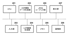
図2は、本実施形態におけるHDR画像の画像符号化装置のブロック図である。同図で、201はCPUであり、各構成の処理の全てに関わる。202は入力部であり、ユーザからの指示や、符号化対象のHDR画像データなどを入力する部分である。これは、キーボードやマウスなどのポインティングシステムを含む。符号化対象のHDR画像データの発生源は撮像装置とするが、入力部202にその撮像装置が接続されても良いし、符号化対象のHDR画像データを格納した記憶媒体が入力部202に接続されても構わない。場合によっては、HDR画像データを保持するサーバがネットワーク上に存在し、入力部202はそのサーバからダウンロードしても構わない。203はHDR補助データ生成部、204はLDR画像生成部である。205はJPEGコーデック部(非可逆符号化部)であり、1コンポーネント当り8bitの非圧縮画像データをJPEG符号データに変換したり、JPEG符号データを復号し非圧縮画像データに変換する。206はメモリであり、ROMやRAMを含み、処理に必要なプログラム、データ、作業領域などをCPU201に提供する。207は表示部であり、通常は液晶ディスプレイなどが用いられる。208は蓄積部であり、画像データ、プログラムなどを蓄積する部分で、通常はハードディスクなどが用いられる。また、以降のフローチャートの処理に必要な制御プログラムは、蓄積部208に格納されているか、メモリ206のROMに格納されているものとする。蓄積部208に格納されている場合は、一旦メモリ206内のRAMに読み込まれてから実行される。なお、システム構成については、上記以外にも様々な構成要素が存在するが、本実施形態の主眼ではないので、その説明は省略する。
[First Embodiment]
FIG. 2 is a block diagram of an image coding device for an HDR image according to the present embodiment. In the figure, 201 is a CPU and is involved in all the processing of each configuration.
本実施形態におけるHDR補助データの生成方法は、ISO/IEC 18477−2で規定されている方法を基本とする。すなわち、HDR画像データとLDR画像データの輝度成分比(Yレシオ;Yratio)を利用する方法である。Yレシオを使って、LDR画像データをHDRのレンジに戻して、オリジナルのHDR画像データとの色差成分の差分を生成する。そして、Yレシオと色差成分を8ビット化してJPEG符号化する方法である。 The method for generating HDR auxiliary data in the present embodiment is based on the method specified in ISO / IEC 18477-2. That is, it is a method of using the luminance component ratio (Y ratio; Y ratio) of the HDR image data and the LDR image data. The Y ratio is used to return the LDR image data to the HDR range and generate a difference in color difference components from the original HDR image data. Then, it is a method of converting the Y ratio and the color difference component into 8 bits and JPEG coding.
符号化装置に入力されたHDR画像データをLDR画像とHDR補助データに分けて、圧縮する方法について図3を用いて説明する。なお、ISO/IEC 18477−2で規定されている処理と同様の部分については、ここでの詳しい説明は割愛する。 A method of dividing the HDR image data input to the coding apparatus into an LDR image and HDR auxiliary data and compressing them will be described with reference to FIG. The details of the processing specified in ISO / IEC 18477-2 will be omitted here.
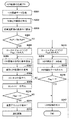
ステップS301にて、CPU201は、入力部202を介して符号化対象のHDR画像データを入力し、メモリ206に格納する。ステップS302にて、CPU201は、LDR画像生成部204を制御し、入力したHDR画像データに対してトーンマッピング処理を行わせる。LDR画像生成部204は生成した線形LDR画像データを、メモリ206に保存する。また、LDR画像生成部204は、線形LDR画像を作成する際に、低輝度の画素数をカウントし、保持するものとする。この低輝度画素数のカウント処理の詳細は後述する。
In step S301, the
ステップS303にて、CPU201は、上記で得た低輝度画素数から、低輝度画素数の割合RLPを算出する。すなわち、画像全体の低輝度画素数をC、入力されたHDR画像の幅がw画素、高さがh画素とすると、RLP=C/(w×h)として算出できる(実施形態では、w=1920、h=1080)。
In step S303, the
ステップS304にて、CPU201は、算出して得られたRLPと、予め決められた閾値Th_RLPを比較する。RLPが閾値Th_RLPより大きければステップS305へ処理を進め、そうでなければステップS313へ処理を進める。実施形態では、閾値Th_RLPは“0.5”とする。すなわち、低輝度画素が画像全体の半分以上を占める場合には、符号化対象のHDR画像は低輝度画素の割合が大きい画像として判断し、ステップS305へ進む。ステップS305およびステップS313では、HDR補助データ作成時にローカルデコードしたLDR画像を使用するかどうかを示す情報を、メモリ206に予め確保したフラグFlagに設定する。具体的には、ステップS305にて、CPU201は、HDR補助データ作成時にローカルデコードしたLDR画像を使用することを示す値“1”をフラグFlagに設定する。ステップS313にて、CPU201は、ステップS302で作成した線形LDR画像を用いてHDR補助データを作成することを示す値“0”をフラグFlagに設定する。従って、S313に進んだ場合、LDR画像のローカルデコードは行わないことになる。
In step S304, the
次に、LDR画像をローカルデコードする場合のステップS305以降の処理を説明する。ステップS305にて、CPU201はフラグFlagを“1”に設定すると、処理をステップS306に進める。ステップS306にて、CPU201は、LDR画像の符号化条件として、サブサンプリング情報および量子化ステップに関する情報を取得する。次に、ステップS307にて、CPU201は線形LDR画像の色変換を行う。すなわち、CPU201は、線形色空間のLDR画像にガンマ処理を施し、sRGB色空間の画像データに変換し、その後、RGB/YCC変換を行う。また、CPU201は、ステップS306において取得した情報によって、サブサンプリングが必要な場合は、色差成分Cb,Crのサブサンプリングを行う。これらの処理については、一般的な処理であり、ISO/IEC 18477−2にも記載されているので、ここでの詳細な説明は割愛する。ステップS308にて、CPU201は、JPEGコーデック部205を制御し、ステップS307で得られたLDR画像のYCCデータをマクロブロックに分割させ、DCT変換及び量子化処理を行わせる。これらの処理についても一般的な処理であるため、ここでの詳細な説明を割愛する。ステップS309にて、CPU201は、JPEGコーデック部205を制御し、量子化されたDCT係数を、JPEG(ISO/IEC10918)に規定された方法でエントロピー符号化する。JPEGコーデック部205は、生成した符号化データを、一旦、メモリ206に格納する。
Next, the processes after step S305 in the case of locally decoding the LDR image will be described. When the
次に、ステップS310にて、CPU201は、フラグFlagの値が“1”であるかどうかを判定する。すなわち、ステップS304でローカルデコードしたLDR画像を使用すると判定された場合、Flagの値が1であるので、CPU201は処理をステップS311に進める。また、Flagの値が0である場合には、CPU201はステップS317に処理を進める。ここでの説明では、ステップS305を経ているので、ステップS311に処理が進むものとして説明する。
Next, in step S310, the
ステップS311にて、CPU201は、JPEGコーデック部206を制御し、ステップS308で得られた量子化後のDCT係数を逆量子化、逆DCTすることで、ローカルデコード後のLDR画像のYCCデータを取得する。なお、ローカルデコードでは、符号化データから開始してしても良いが、JPEGでのエントロピー(ハフマン符号化)そのものは可逆であるので、途中の量子化後の係数からローカルデコードを行っている。本処理についても、DCT/量子化と同様に詳細な説明は割愛する。ステップS312にて、CPU201は、ステップS311で取得したYCCデータに逆色変換をし、線形LDR画像を生成し、メモリ206に保存し、処理をステップS314に進める。すなわち、CPU201は、YCC/RGB変換によってローカルデコードしたRGB画像データを取得し、さらに、逆ガンマ処理を行うことで、ローカルデコードした線形RGB画像データを取得する。なお、メモリ206には、既にステップS302で作成した線形LDR画像が保存されているが、そのデータをローカルデコードした結果で上書きすることになる。ステップS314にて、CPU201は、HDR補助データ生成部203を制御し、ステップS312で得られたローカルデコードの線形RGB画像を入力として、LDRからHDRの精度(8ビットから16ビット)に戻すためのHDR補助データを作成させる。この処理の詳細は、図5を用いて後述する。次に、ステップS315にて、CPU201は、ステップS314で作成したHDR補助データを、ISO/IEC 18477−2記載の方法で出力する。そして、ステップS316にて、フラグFlagが“1”(ローカルデコードを行うことを示している)であるかどうかを判定する。フラグFlagの値が“1”であれば、既にLDR画像のJPEG符号データがメモリ206に作成されているものと判断し、CPU201は処理をステップS317に進める。また、フラグFlagの値が“0”であれば、処理をステップS306に進め、LDR画像のJPEG符号データの作成処理に進む。ステップS317にて、CPU201は、LDR画像の符号化データを、ISO/IEC 18477−1記載の方法で出力し、このフローを終了する。
In step S311 the
次に、ステップS304にて、符号化対象のHDR画像が、低輝度画素の割合が小さい画像として判断された場合を説明する。 Next, a case where the HDR image to be encoded is determined as an image having a small proportion of low-luminance pixels in step S304 will be described.
ステップS313にて、CPU201は、フラグFlagに“0”を設定、すなわち、ローカルデコードしないとして設定する。そして、ステップS314、315にて、CPU201は、HDR補助データ生成部203を制御し、ステップS302で得られた線形LDR画像を入力として、HDR補助データを作成、出力させる。次にステップS316にて、CPU201は、フラグFlagの値が“1”であるか否かを判定し、“1”であればステップS317、“0”であればステップS306に処理を進める。ここでの説明では、ステップS313からの説明であるので、処理はステップS306へ進み、CPU201は、LDR画像の符号化処理を行う。ステップS306からステップS309までは、上述の説明と同じである。ステップS310では、再びフラグFlagを参照する。今回は、ステップS313の処理を経ているため、フラグFlagは“0”である。したがって、ローカルデコードをする必要がないため、ステップS317へ進み、LDR画像の符号化データを出力し、このフローを終了する。
In step S313, the
次に、ステップS302におけるLDR画像生成部204による線形LDR画像の作成処理を、図4を参照して説明する。
Next, the process of creating a linear LDR image by the LDR
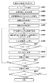
ステップS401にて、LDR画像生成部204は、符号化対象のHDR画像データからLDR画像データを生成するためのトーンカーブを取得する。トーンカーブとは、HDR画像を所定のダイナミックレンジに圧縮するトーンマッピング処理に利用する計算式やテーブルである。トーンマッピング処理は、人間の視覚特性や表示デバイス特性を考慮した手法など様々な手法が提案されている。本実施形態では、各色に対して、図6(a)のようなトーンカーブを描く数式を取得するものとする。他にもルックアップテーブルや、図6(a)のトーンカーブ上のサンプリングされた数点の値など、トーンカーブを特定できる情報であれば、どのようなものでも構わない。
In step S401, the LDR
ステップS402にて、LDR画像生成部204は、画像の幅wと高さhを取得する。本実施形態の場合、幅w=1920[画素]、高さh=1080[画素]である。ステップS403にて、LDR画像生成部204は、低輝度の画素値を数えるためのカウンタCに、ゼロを代入して初期化する。そして、ステップS404にて、LDR画像生成部204は、画像の高さ方向をカウントするための変数yに、ゼロを代入して初期化する。また、ステップS405にて、LDR画像生成部204は、画像の幅方向をカウントするための変数xにゼロを代入して初期化する。なお、本実施形態では、画像の左上隅(0,0)からラスタ順に以下の処理を行う。
In step S402, the LDR
ステップS406では、LDR画像生成部204は、HDR画像内の(x,y)で表わされる画素位置の画素値PHを取得する。本実施形態では、画素値PHはそれぞれ16ビットのR,G,Bの値で構成される。ステップS407では、ステップS401で取得したトーンカーブを使って、画素値PHをLDR画像の画素値PL(8ビット)にマッピングする。そして、LDR画像生成部204は、メモリ206に確保した、線形LDR画像用の領域内の画素位置(x,y)に、画素値PLを保存する。次に、ステップS408にて、LDR画像生成部204は、画素値PHの値から、画素位置(x,y)の輝度値Y_hdrを算出する。本実施形態では、輝度Y_hdrは8ビットのJPEG圧縮と同様に、ISO/IEC 18477−1で規定された変換式で算出される。ステップS409にて、LDR画像生成部204は、ステップS407で算出したY_hdrと予め決められた輝度の閾値Th_Yとを比較する。輝度値Y_hdrがしきい値Th_Yより小さければステップS410へ、そうでなければステップS411へ進む。本実施形態では、図6に示すように、マッピングしたLDRの画素値が“96”となる値“4550”を閾値Th_Yとする。したがって、輝度値Y_hdrが“4550”よりも小さい値であれば、処理はステップS410に進み、LDR画像生成部204は低輝度画素を数えるカウンタCに“1”を加算する。また、輝度値Y_hdrが4550以上であれば、処理はステップS410の処理は行わず、ステップS411に処理が進む。このステップS411にて、LDR画像生成部204は、画素位置(x,y)に対してトーンマップ処理および低輝度画素の判定が終了したので、画像の水平方向のカウンタxに“1”を加算する。そして、ステップS412にて、画像の横方向のカウンタxが画像幅wと同じ値であるか判定する。同じ値であれば、この画像の右端まで処理したものと判定し、ステップS413へ進む。そうでなければ、まだ右端に到達していないものと判定し、ステップS406へ処理を戻す。ステップS413にて、LDR画像生成部204は、画像の高さ方向の変数yに“1”を加算する。そして、ステップS414にて、LDR画像生成部204は、変数yと画像の高さhを比較し、同じであれば、この画像のすべての画素の処理を終えたものとして、このフローを終了する。異なる場合には、ステップS405に処理を戻して、残りの画素の処理を続ける。
In step S406, the LDR
以上の処理により、HDR画像と同じ大きさの線形色空間のLDR画像(線形LDR画像)と、HDR画像の輝度成分Y_hdr、および低輝度画素数Cを得ることができる。なお、線形LDR画像は1コンポーネント当り8ビットの整数値(0〜255)の画像データである。 By the above processing, an LDR image (linear LDR image) having a linear color space having the same size as the HDR image, a luminance component Y_hdr of the HDR image, and a low-luminance pixel number C can be obtained. The linear LDR image is 8-bit integer value (0 to 255) image data per component.
次に、図5を参照して、ステップS314における、HDR補助データ生成部203によるHDR補助データ作成処理を説明する。HDR補助データの作成方法については、ISO/IEC 18477−2で記載されている方法をそのまま使用すれば良いので、詳細な説明は割愛する。
Next, with reference to FIG. 5, the HDR auxiliary data creation process by the HDR auxiliary
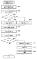
まず、ステップS501にて、HDR補助データ生成部203は、ステップS301で取得したHDR画像の輝度値Y_hdrを取得する。輝度値Y_hdrは、ステップS302の線形LDR画像作成時に既に計算されているので、その値を保存していれば、ここで計算する必要はない。ステップS502にて、HDR補助データ生成部203は、メモリ206の線形LDR画像用の領域から線形LDR画像データを取得する。フラグFlagに“0”が設定されている場合は、メモリ203にはステップS302で作成された線形LDR画像が保存されている。一方、フラグFlagが“1”に設定されている場合は、メモリ203には、ステップS302で作成された線形LDR画像が、ステップS312の処理によってローカルデコード結果の線形LDR画像によって上書きされた画像が保存されている。ステップS503にて、HDR補助データ生成部203は、ステップS502で取得した線形LDR画像の各画素について輝度値Y_ldrを算出する。輝度値の計算方法は、ISO/IEC 18477−2で規定された変換式を用いる。ステップS504にて、HDR補助データ生成部203は、ISO/IEC 18477−2で規定されている方法に従って、ステップS501で取得したY_hdrとステップS503で取得したY_ldrを用いて、次式に従い全画素のYレシオ(Y_ratio)を計算する。
Y_ratio(x,y)=Y_hdr(x,y)/(Y_ldr(x,y)+nf)
ここで、nfは、ノイズ付加部106により付加されるノイズである。これにより、ゼロ割を防ぐことができる。
First, in step S501, the HDR auxiliary
Y_ratio (x, y) = Y_hdr (x, y) / (Y_ldr (x, y) + nf)
Here, nf is noise added by the
ステップS505にて、HDR補助データ生成部203は、ISO/IEC 18477−2で規定されている方法にしたがって、HDR画像と線形LDR画像の各画素位置毎にRGB値の差分DifRGBを算出する。ステップS506にて、HDR補助データ生成部203は、ステップS505で算出した画素位置毎のDifRGBを、ステップS504で算出した同一画素位置のY_ratioで割ることでスケール変換する。そして、HDR補助データ生成部203は、ISO/IEC 18477−2で規定されている方法に従って、各画素位置に対応するHDR補助データの色差成分CC_hdrを算出する。ステップS507にて、HDR補助データ生成部203は、CC_hdrをステップS503で算出したY_ldrで正規化し、CC_normを取得する。ステップS508にて、HDR補助データ生成部203は、ステップS504で取得したY_ratioの対数をとり、Y_logを算出する。ステップS509にて、HDR補助データ生成部203は、すべての画素のCC_normの値から、最大値Max_CC(Max_CbとMax_Cr)と最小値Min_CC(Min_CbとMin_Cr)を取得する。そして、HDR補助データ生成部203は、Max_CCとMin_CCの範囲でCC_normを量子化し、CC_normを8ビット化したCC_xtを取得する。ステップS511にて、HDR補助データ生成部203は、ステップS508で取得したY_logについて、全ての画素の最大値Max_logと最小値Min_logを取得する。そして、HDR補助データ生成部203は、Max_logとMin_logの範囲でY_logを量子化し、8ビット化したY_xtを取得する。そして、ステップS513において、Y_xtとCC_xtをJPEG方式で符号化し、このフローを終了する。
In step S505, the HDR auxiliary
本実施形態では、LDR画像において輝度値が96以下となる画素数が、画像全体の半数を超える場合に、LDR画像をローカルデコードした結果を使ってHDR補助データを作成する。つまり、低輝度画素数が非常に多い場合のみ処理負荷が高いローカルデコード処理を実施し、復号時のHDR画像の画質向上を図る。これは人間の視覚特性上、低輝度に対する感度が大きいためである。そのため、処理負荷が高くても、復号時のHDR画像の画質を向上する効果が大きい。一方、低輝度画素の割合が多くない画像の場合には、復号時のHDR画像の画質を向上させる効果が少ないため、ローカルデコード処理を行わず、符号化にかかる処理負荷を低減させることができる。したがって、本実施形態によれば、復号時の画質向上の効果が大きい時のみ、符号化時の処理負荷が大きくなるローカルデコード処理を実行することが容易になる。 In the present embodiment, when the number of pixels whose brightness value is 96 or less in the LDR image exceeds half of the entire image, HDR auxiliary data is created using the result of local decoding of the LDR image. That is, the local decoding process, which has a high processing load, is performed only when the number of low-luminance pixels is very large, and the image quality of the HDR image at the time of decoding is improved. This is because human visual characteristics have a high sensitivity to low brightness. Therefore, even if the processing load is high, the effect of improving the image quality of the HDR image at the time of decoding is great. On the other hand, in the case of an image in which the proportion of low-luminance pixels is not large, the effect of improving the image quality of the HDR image at the time of decoding is small, so that the processing load required for coding can be reduced without performing the local decoding process. .. Therefore, according to the present embodiment, it becomes easy to execute the local decoding process in which the processing load at the time of encoding becomes large only when the effect of improving the image quality at the time of decoding is large.
[第1の実施形態の変形例]
上記の第1の実施形態では、符号化対象のHDR画像全体に対する低輝度画素値が占める割合を用いて、ローカルデコード処理の有無を決定した。図3のステップS302で、画像全面分、すなわち1920×1080画素の線形LDR画像を作成すると共に、低輝度画素値をカウントした。そのため、線形LDR画像作成後に、ローカルデコードの有無を判定できた。しかし、画像全体の情報が必要になるため、並列化処理ができず、メモリ使用量も大きくなってしまう。
[Modified example of the first embodiment]
In the first embodiment described above, the presence or absence of the local decoding process is determined using the ratio of the low-luminance pixel value to the entire HDR image to be encoded. In step S302 of FIG. 3, a linear LDR image for the entire surface of the image, that is, 1920 × 1080 pixels was created, and the low-luminance pixel values were counted. Therefore, it was possible to determine the presence or absence of local decoding after creating the linear LDR image. However, since the information of the entire image is required, the parallel processing cannot be performed and the memory usage becomes large.
たとえば、マクロブロック(8×8画素)の高さと同じ8ラインずつに画像を分割し、HDR画像の圧縮フローを実行し、並列処理で高速化することを考える。LDR画像の作成を終えた8ライン分の符号化を行うと同時に、次の8ラインのLDR画像の作成を並列して実行する。しかし、画像全体における低輝度画素の割合が分からないと、ローカルデコードの有無が決まらない。そのため、HDR補助データの作成は、ステップS302の処理が終わるまで始めることができず、並列処理できない。さらに、ローカルデコードの有無が決定するまで、ステップS308で得られるLDR画像の量子化値をすべて保存しておく必要がある。そのため、LDR画像のすべての量子化値を保持しなければならない。あるいは、LDR画像の符号データだけを保持しておき、ローカルデコードが必要になった時点で復号し、線形LDR画像を作成することもできる。この場合、LDR画像のメモリ使用量は符号データ分と、8ライン分のメモリのみで良いが、エントロピー符号化を復号する時間が必要になり、処理全体が遅くなる。 For example, consider dividing an image into eight lines, which are the same height as a macroblock (8 × 8 pixels), executing a compression flow of an HDR image, and speeding up by parallel processing. At the same time as coding for the eight lines for which the LDR image has been created is performed, the creation of the next eight lines of the LDR image is executed in parallel. However, if the proportion of low-luminance pixels in the entire image is not known, the presence or absence of local decoding cannot be determined. Therefore, the creation of HDR auxiliary data cannot be started until the processing of step S302 is completed, and parallel processing cannot be performed. Further, it is necessary to store all the quantized values of the LDR image obtained in step S308 until the presence or absence of local decoding is determined. Therefore, all quantization values of the LDR image must be retained. Alternatively, it is also possible to retain only the code data of the LDR image and decode it when local decoding is required to create a linear LDR image. In this case, the memory usage of the LDR image may be only the memory for the code data and the memory for 8 lines, but it takes time to decode the entropy coding, and the entire process is slowed down.
上述の問題を解決する方法として、本変形例では、マクロブロック単位でローカルデコードの有無を切り替えるものである。以下、本変形例の具体的な処理を、図7のフローを使って説明する。なお、本変形例において、第1の実施形態と同じ動作の処理には、同符号を付与し、その詳細な説明は割愛する。また、以下の説明では、HDR補助データ生成部203、LDR画像生成部204、JPEGコーデック部205等の各種処理部が、CPU201によって実行される例を説明する。
As a method of solving the above-mentioned problem, in this modification, the presence / absence of local decoding is switched in macroblock units. Hereinafter, the specific processing of this modification will be described with reference to the flow of FIG. In this modification, the same reference numerals are given to the processes of the same operation as in the first embodiment, and detailed description thereof will be omitted. Further, in the following description, an example in which various processing units such as the HDR auxiliary
CPU201は、ステップS306にて、LDR画像の符号化条件を取得する。次に、ステップS701にて、CPU201は、HDR画像のサイズ、すなわち幅wと高さhを取得する。本実施形態の場合、幅w=1920画素、高さh=1080画素である。ステップS702にて、CPU201は、処理すべきマクロブロック数Nを算出する。本実施形態では、画像の幅wが1920画素であるので、N=1920÷8=240と計算できる。続くステップS703にて、CPU201は、HDR画像データを先頭から順に8ライン取得する。8ラインとは、マクロブロックの高さと一致するライン数である。ステップS704にて、CPU201は、処理済みのマクロブロックをカウントするためのカウンタMにゼロを代入し初期化する。ステップS705にて、CPU201は、マクロブロック単位でLDR画像の圧縮処理を行う。この処理については、後に図8を使って説明する。ステップS706にて、CPU201は、HDR補助データ作成に必要なマクロブロックのCC_normとY_logを作成する。この処理は、第1の実施形態で説明した図5のステップS501からステップS508を、マクロブロックに対して適用した処理である。第1の実施形態で説明済みのため、本変形例における処理フローとその説明は割愛する。次にステップS707にて、CPU201は、マクロブロックのカウンタMに“1”を加算する。ステップS708にて、CPU201は、カウンタMとステップS703で算出した処理すべきマクロブロック数Nを比較する。M=Nであれば、現時点で入力された8ライン分のHDR画像の処理が終了したと判断し、CPU201は処理をステップS709へ進める。そうでなければ、CPU201はステップS705へ処理を戻す。ステップS709にて、CPU201は、HDR画像の最後のラインまで処理が終わったかどうかを判定する。本実施形態では、ステップS703で入力されたライン数を加算しておき、ステップS701で取得したHDR画像の高さと同じになった場合、最後のラインまで終了したと判定する。最後のラインまで終了した場合、CPU201は処理をステップS710へ進める。そうでなければ、CPU201は、ステップS703へ処理を戻し、次の8ラインを取得する。
In step S306, the
ステップS710にて、CPU201は、ステップS706で得られたCC_normとY_logを使って、HDR補助データの圧縮処理を行う。この処理は、第1の実施形態で説明した図5のフローチャートにおけるステップS509からステップS513までの処理と同じであるので、その説明は割愛する。なお、図5のフローのステップS509以降の処理において、画像全体における最大値および最小値を取得する必要がある。そのため、LDR画像の作成を8ラインずつ実施する本変形例においては、ステップS508までと、それ以降で処理を分割する必要がある。次にステップS315にて、CPU201は、ステップS710で作成されたHDR補助データを出力する。そして、ステップS317において、CPU201は、ステップS705で作成されたLDRの圧縮データをLDR情報として出力する。ステップS315とステップS317の処理は第1の実施形態と同じであるので、ここでの説明は省略する。
In step S710, the
次に、ステップS705のマクロブロック単位のLDR画像圧縮処理を図8のフローチャートに従って説明する。 Next, the LDR image compression process for each macroblock in step S705 will be described with reference to the flowchart of FIG.
ステップS801にて、CPU201は、マクロブロック単位で線形LDR画像を作成する。この方法については、後に図9を用いて説明する。ステップS802にて、CPU201は、ステップS801で線形LDR画像を作成する際にカウントした低輝度画素の数から、着目マクロブロックの低輝度画素の割合RLP_mを算出する。マクロブロックのサイズは8×8画素である。故に、ステップS801で得られる低輝度画素数をCとすると、RLP_m=C/64となる。ステップS803にて、CPU201は、RLP_mと、あらかじめ決められた閾値Th_RLPを比較する。RLP_mが閾値Th_RLPより大きければ、CPU201は処理をステップS305へ進める。本変形例では、閾値Th_RLPは0.5とする。したがって、本変形例の場合、1つのマクロブロックに低輝度の画素が33以上あれば、処理はステップS305へ進むことになる。ステップS305にて、CPU201は、ローカルデコードを行うことを示すためフラグFlagに“1”を代入する。一方、RLP_mが閾値以下となって、S313に処理が進んだ場合、CPU201は、ローカルデコードを行わないことを示すためフラグFlagに“0”を代入する。ステップS307からステップS310までは第1の実施形態と同様の動作をする。ステップS310にて、CPU201は、フラグFlagが“1”であるか否かを判定する。フラグFlagが“1”の場合、CPU201は処理をステップS311へ進め、そうでなければ、本フローを終了する。ステップS311およびステップS312は第1の実施形態と同様の動作をする。ただし、S311、312における処理対象は、着目マクロブロックとなる。ステップS804では、ステップS312で得られたローカルデコード後の画像データで、ステップS801で作成した着目マクロブロックの線形LDR画像を上書きし、このフローを終了する。
In step S801, the
次に、ステップS801のマクロブロック単位の線形LDR画像の作成処理を図9のフローを参照して説明する。 Next, the process of creating a linear LDR image for each macroblock in step S801 will be described with reference to the flow of FIG.
基本的には、第1の実施形態の図4で画像全体に対して行った処理を、本変形例に合わせて1つのマクロブロックに対して行うことになる。 Basically, the processing performed on the entire image in FIG. 4 of the first embodiment is performed on one macroblock according to the present modification.
ステップS401にて、CPU201は、トーンマッピング処理に用いるトーンカーブを取得し、ステップS403に処理を進める。ステップS403からステップS411までは、第1の実施形態と同様の処理である。ステップS901にて、CPU201は、変数xとマクロブロックの幅=8を比較する。変数x=8であれば、CPU201は、このマクロブロックの右端まで処理を終えたものと判断し、処理をステップS413へ進める。また、変数xがマクロブロック幅に達していない場合、CPU201は着目画素の右隣の画素を処理するためにステップS406へ処理を戻す。ステップS413にて、CPU201は、マクロブロックの高さ方向の変数yに“1”を加算する。ステップS902にて、CPU201は、変数yとマクロブロックの高さ=8と比較する。yが8であればこの処理を終了し、そうでなければ次のラインの先頭から処理を進めるために、ステップS405へ処理を戻す。
In step S401, the
本変形例の処理によれば、マクロブロック単位でローカルデコードの有無を切り替えることができる。そのため、マクロブロック境界にアーチファクトが発生するリスクは高くなる。しかし、LDRの符号化に要するメモリ使用量を削減でき、並列処理による高速化も行いやすいという効果が期待できる。 According to the processing of this modification, the presence / absence of local decoding can be switched for each macroblock. Therefore, the risk of artifacts occurring at macroblock boundaries is high. However, the effect that the memory usage required for LDR coding can be reduced and the speed can be easily increased by parallel processing can be expected.
なお、本実施形態では、マクロブロックと同じ高さである8ラインずつデータを読み込み処理したが、マクロブロックの高さ(=8)の倍数であれば、何ラインであっても構わない。 In the present embodiment, the data is read and processed for each of eight lines having the same height as the macroblock, but any number of lines may be used as long as it is a multiple of the height (= 8) of the macroblock.
[第2の実施形態]
第1の実施形態では、図6(a)のようにHDR画像のデータがとり得る範囲すべてをカバーするトーンカーブを使用した。このように画像によらず一意に決まるトーンカーブを適用するトーンマッピング処理は、計算コストが小さく、リアルタイム性が要求される場合には好まれる。しかし、入力されるHDR画像がこの範囲をすべて使用していないことがある。実際、個々のHDR画像のダイナミックレンジは様々であり、取り得るデータ範囲の一部しか使っていない画像がほとんどである。たとえば、第1の実施形態では、入力されたHDR画像の画素値が“4550”より小さい値であれば低輝度画素としてカウントしたが、入力HDR画像の最小画素値が“4550”であると、ローカルデコードが必要と判断されることが全くない。
[Second Embodiment]
In the first embodiment, as shown in FIG. 6A, a tone curve that covers the entire range that the HDR image data can take is used. The tone mapping process that applies a tone curve uniquely determined regardless of the image in this way is preferred when the calculation cost is low and real-time performance is required. However, the input HDR image may not use all of this range. In fact, the dynamic range of individual HDR images varies, and most images use only part of the possible data range. For example, in the first embodiment, if the pixel value of the input HDR image is smaller than "4550", it is counted as a low-luminance pixel, but if the minimum pixel value of the input HDR image is "4550", it is counted. It is never determined that local decoding is needed.
一方、符号化対処のHDR画像のダイナミックレンジに依存したトーンカーブを用いてトーンマッピングを行うことも考えられる。たとえば、入力HDR画像の画素値の最小値が“4550”で、最大値が“50530”である場合、図6(b)のようなトーンカーブを生成し、LDR画像を作成する。このように個々の符号化対象のHDR画像のダイナミックレンジに合わせたトーンカーブを使用する方が、計算コストはかかるが、より綺麗(高品位)なLDR画像を復号できる符号データを作成することができる。つまり、計算コストよりも画質を重視していると判断できる。 On the other hand, it is also conceivable to perform tone mapping using a tone curve that depends on the dynamic range of the HDR image for which coding is dealt with. For example, when the minimum value of the pixel value of the input HDR image is "4550" and the maximum value is "50530", a tone curve as shown in FIG. 6B is generated to create an LDR image. It is more costly to use the tone curve that matches the dynamic range of the HDR image to be encoded in this way, but it is possible to create code data that can decode a cleaner (high-quality) LDR image. it can. In other words, it can be judged that the image quality is more important than the calculation cost.
本第2の実施形態では、HDR画像の画素値の取り得る全範囲に対応する固定トーンカーブ(図6(a))を用いて符号化するのか、符号化対象のHDR画像に依存したトーンカーブを生成した上で符号化するのかを、ユーザが入力部202を介して設定する例を説明する。そして、その設定に応じてローカルデコードの有無を切り換える。
In the second embodiment, coding is performed using a fixed tone curve (FIG. 6A) corresponding to the entire possible range of pixel values of the HDR image, or a tone curve depending on the HDR image to be encoded. An example will be described in which the user sets via the
なお、本第2の実施形態におけるLDR画像生成部204は、固定トーンカーブを用いることが設定された場合には、図6(a)に示すトーンカーブを用いてLDR画像を生成する。一方、符号化対象のHDR画像に依存するトーンカーブを用いることが設定された場合、LDR画像生成部204は、符号化対象のHDR画像の画素の最大値と最小値とを求め、その範囲の出力値を0乃至255とする曲線を設定した上で、LDR画像を生成するものとする。
When the fixed tone curve is set to be used, the LDR
以下、本第2の実施形態の処理を図10のフローチャートに従って説明する。なお、本第2の実施形態において、第1の実施形態と同様の処理には、同じ番号を付与し、その説明は省略する。 Hereinafter, the processing of the second embodiment will be described with reference to the flowchart of FIG. In the second embodiment, the same processing as in the first embodiment is given the same number, and the description thereof will be omitted.
ステップS301にて、CPU201はHDR画像のデータを取得し、メモリ206に格納する。次に、ステップS302にて、CPU201はLDR画像生成部204を制御し、線形LDR画像を作成させる。生成された線形LDR画像はメモリ206に格納される。なお、LDR画像の生成手順は先に説明した通りである。次に、ステップS1001にて、CPU201は、ステップS302で使用したトーンカーブが、符号化対象のHDR画像に依存したトーンカーブであったかを判定する。この判定は、ユーザの設定から判定しても良い。
In step S301, the
符号化対象のHDR画像に依存したトーンカーブを用いたと判定された場合、CPU201は画質重視であると判断し、処理をステップS305へ進める。ステップS305にて、CPU201は、ローカルデコードしたLDR画像をHDR補助データ作成時に使用するようにするため、フラグFlagに“1”を設定する。一方、ステップS302で使用したトーンカーブが、符号化対象のHDR画像に依存しない、固定トーンカーブであった場合、CPU201は、ステップS1001からステップS313に処理を進める。ステップS313にて、CPU201は、LDR画像のローカルデコードをしないことを示すため、フラグFlagに“0”を設定する。ステップS306以降は、第1の実施形態と同様の動作であるので、ここでの説明は割愛する。
When it is determined that the tone curve depending on the HDR image to be encoded is used, the
以上の本第2の実施形態によれば、画質優先か否かに応じて、適用するトーンカーブを決定し、LDR画像のローカルデコードをするか、しないかを切り分けることができる。 According to the second embodiment described above, the tone curve to be applied can be determined depending on whether or not the image quality is prioritized, and whether or not the LDR image is locally decoded can be determined.
[第2の実施形態の変形例]
上記第2の実施形態では、符号化対象のHDR画像に依存したトーンカーブを使用するか、固定トーンカーブを使用するかによって、ローカルデコードをする/しないを切り替えた。しかし、符号化対象のHDR画像の輝度値の最小値と最大値から、ローカルデコードをする/しないを切り替えてもよい。つまり、入力HDR画像の最大輝度値が予め設定された閾値より小さい場合には、低輝度の画像であると判定し、ローカルデコードを行う。逆に、入力HDR画像の最小輝度値が予め設定された閾値以上の場合には、ローカルデコードを行わない。本変形例の場合、第1の実施形態のように低輝度画素の割合を計算するわけではない。そのため、ほとんどの画素の輝度が低いにも関わらず、ノイズなどで1画素でも最大輝度値が大きくなると、ローカルデコードされない。しかし、ローカルデコードの有無をより簡易に判定できる。さらに、入力HDR画像のダイナミックレンジに応じたトーンカーブを使用しながらも、HDR補助データ作成にかかる計算コストを小さく抑えることができる。
[Modified example of the second embodiment]
In the second embodiment, local decoding is performed / not switched depending on whether a tone curve depending on the HDR image to be encoded is used or a fixed tone curve is used. However, local decoding may or may not be performed based on the minimum and maximum brightness values of the HDR image to be encoded. That is, when the maximum luminance value of the input HDR image is smaller than the preset threshold value, it is determined that the image has low luminance and local decoding is performed. On the contrary, when the minimum luminance value of the input HDR image is equal to or more than a preset threshold value, local decoding is not performed. In the case of this modification, the ratio of low-luminance pixels is not calculated as in the first embodiment. Therefore, even though the brightness of most of the pixels is low, if the maximum brightness value of even one pixel becomes large due to noise or the like, local decoding is not performed. However, the presence or absence of local decoding can be determined more easily. Further, the calculation cost for creating the HDR auxiliary data can be kept small while using the tone curve according to the dynamic range of the input HDR image.
[第3の実施形態]
トーンマッピング手法としては、大きく2つの手法がある。1つは、第1、第2の実施形態で示したように、画像全体に一様な輝度変換を行うグローバルトーンマッピングである。もうひとつは、画像の局所領域毎に、異なった輝度変換を行うローカルトーンマッピングである。
[Third Embodiment]
There are roughly two tone mapping methods. One is global tone mapping, which performs uniform luminance conversion over the entire image, as shown in the first and second embodiments. The other is local tone mapping, which performs different luminance conversions for each local area of the image.
グローバルトーンマッピングは、画像全体で一様な変換関数を用いるため、画像中のテクスチャ情報の視認性が低下する。一方、ローカルトーンマッピングは、グローバルトーンマッピングに比べて計算コストが高い。しかし、局所領域におけるコントラストを維持することが可能になり、テクスチャ情報の視認性低下を防ぐことができる。 Since global tone mapping uses a conversion function that is uniform throughout the image, the visibility of the texture information in the image is reduced. On the other hand, local tone mapping has a higher calculation cost than global tone mapping. However, it becomes possible to maintain the contrast in the local region, and it is possible to prevent the deterioration of the visibility of the texture information.
この2つのトーンマッピング手法を使い分ける場合に、ローカルデコードをする/しないを切り替える方法について、図11を用いて説明する。なお、トーンマッピングを行う場合のグローバルトーンマッピング、ローカルトーンマッピングのいずれを用いるのかは、入力部202によりユーザが設定するものとする。
When using these two tone mapping methods properly, a method of switching between local decoding and non-local decoding will be described with reference to FIG. It is assumed that the user sets whether to use global tone mapping or local tone mapping when performing tone mapping by the
図11において、図10と同じ処理には同じ番号を付与し、その部分の説明は省略する。 In FIG. 11, the same processing as in FIG. 10 is given the same number, and the description of that part will be omitted.
ステップS301にて、CPU201は、符号化対象のHDR画像のデータを取得し、メモリ206に格納する。次に、ステップS302にて、CPU201は、LDR画像生成部204を制御し、メモリ206に格納されたHDR画像から線形LDR画像を作成させ、作成した線形LDR画像をメモリ206に格納させる。次に、ステップS1101にて、ステップS302で使用したトーンマッピングの手法が、ローカルトーンマッピングだったかどうかを判定する。この判定は、ユーザからの設定から行うものとするが、例えば、1つのHDR画像に対して、複数のトーンカーブを使用した場合に、ローカルトーンマッピングであったと判定しても良い。ローカルトーンマッピングである場合は、CPU201は、画質重視であると判断し、処理をステップS305へ進める。また、ローカルトーンマッピングではない場合には、CPU201は計算コスト重視と判断し、処理をステップS313に進める。以下の処理は第2の実施形態と同様である。
In step S301, the
本第3の実施形態よれば、トーンマッピングの手法により画質重視か、計算コスト重視かを容易に判断でき、LDR画像のローカルデコードをするか、しないかを簡単に切り分けることができる。 According to the third embodiment, it is possible to easily determine whether the image quality is emphasized or the calculation cost is emphasized by the tone mapping method, and it is possible to easily determine whether or not the LDR image is locally decoded.
[第3の実施形態の変形例]
上記第3の実施形態では、ローカルトーンマッピングが選択された場合に、LDR画像の全領域についてローカルデコードした結果を用いた。
[Modified example of the third embodiment]
In the third embodiment, when local tone mapping is selected, the result of local decoding for the entire area of the LDR image is used.
本変形例では、すべてのマクロブロックに対してローカルトーンマッピングを実施するが、マクロブロック毎にローカルデコードをする/しないを切り替える場合について考える。この場合、人間の視覚特性は、低輝度に対する感度が大きいことを考慮すると、暗い領域として分類されたマクロブロックのみ、ローカルデコードすることで、計算コストを軽減することができる。このような処理について、図12を用いて説明する。なお、第1乃至第3の実施形態と同じ処理には同じ番号を付与し、詳細な説明は割愛する。 In this modification, local tone mapping is performed for all macroblocks, but consider the case of switching between local decoding and non-local decoding for each macroblock. In this case, considering that the human visual characteristics are highly sensitive to low brightness, the calculation cost can be reduced by locally decoding only the macroblocks classified as dark regions. Such processing will be described with reference to FIG. The same numbers are assigned to the same processes as in the first to third embodiments, and detailed description thereof will be omitted.
ステップS301にて、CPU201は、符号化対象のHDR画像データを取得し、メモリ206に格納する。次いで、ステップS1201にて、CPU201は、HDR画像を、暗い領域と明るい領域の2つに分類し、領域分割する。領域分割の方法は、明るい領域と暗い領域に2分できるのであれば、どのような方法を用いても構わない。
In step S301, the
本変形例では、各画素の輝度値を見て、16ビットで取り得る輝度範囲(0〜65535)の真ん中(43678)未満であれば暗い領域の画素として分類する。それ以外であれば明るい領域の画素として分類する。その後、例えば128画素×128画素未満の領域は隣接領域と統合し、領域分割を終了するものとする。 In this modification, the brightness value of each pixel is examined, and if it is less than the middle (43678) of the brightness range (0 to 65535) that can be taken by 16 bits, it is classified as a pixel in a dark region. Otherwise, it is classified as a pixel in a bright region. After that, for example, an area of less than 128 pixels × 128 pixels is integrated with an adjacent area, and the area division is completed.
ステップS702にて、CPU201は、画像全体に含まれるマクロブロック数Nを算出する。実施形態では、画像サイズが1920×1080画素であるので、N=(1920/8)×(1080/8)=32400と算出できる。ステップS704にて、CPU201は、マクロブロック用のカウンタMにゼロを代入して初期化する。ステップS1202にて、CPU201は、マクロブロック単位のLDR画像圧縮を行う。この処理については、後に図13を用いて説明する。
In step S702, the
ステップS707にて、CPU201は、マクロブロック用カウンタMに“1”を加算する。ステップS708にて、CPU201は、マクロブロック用カウンタMの値と、マクロブロック数Nとを比較する。同じであれば、CPU201は、すべてのマクロブロックについてLDR画像圧縮を終えたものと判断し、処理をステップS314へ進める。そうでなければ、CPU201は処理をステップS1202へ戻す。ステップS314、ステップS315、ステップS317は第1の実施形態と同様の動作を行い、このフローを終了する。
In step S707, the
次に、ステップS1202の処理を、図13を参照して説明する。なお、図13において、図9と同様の動作には同じ番号を付与し、その説明は省略する。 Next, the process of step S1202 will be described with reference to FIG. In FIG. 13, the same operation as in FIG. 9 is given the same number, and the description thereof will be omitted.
ステップS801にて、CPU201は、マクロブロック単位の線形LDR画像を作成する。ステップS1301にて、CPU201は、現在処理中のマクロブロック内に、ステップS1202の結果、暗い領域として判定された画素が32画素以上(半数以上)含まれているかどうか判定する。32画素以上が暗い領域であれば、CPU201はステップS305へ処理を進め、このマクロブロックはローカルデコードするものとして、フラグFlagに“1”を代入する。一方、ステップS313に処理が進んだ場合、CPU201は、ローカルデコードしないものとするため、フラグFlagに“0”を代入する。ステップS307からステップS804は、第1の実施形態およびその変形例で説明したのと同様の処理を行い、このフローを終了する。
In step S801, the
本変形例によれば、低輝度領域に分類されるマクロブロックのみローカルデコードを実施する。そのため、HDR画像デコード時に処理が切り替わったマクロブロックの境界部分にアーチファクトが出る可能性はある。しかし、ローカルトーンマッピングを行う場合であっても、ローカルデコードするマクロブロックを限定することで、HDR補助データ作成にかかる計算コストを削減することができる。 According to this modification, local decoding is performed only for macroblocks classified in the low-luminance region. Therefore, there is a possibility that an artifact will appear at the boundary portion of the macro block whose processing has been switched during HDR image decoding. However, even when local tone mapping is performed, the calculation cost required for creating HDR auxiliary data can be reduced by limiting the macroblocks to be locally decoded.
なお、本変形例では、すべてのマクロブロックに対してローカルトーンマッピングする方法について説明したが、第3の実施形態のように、グローバルトーンマッピングとローカルトーンマッピングのどちらかを選択する場合に適用してもよい。 In this modification, the method of local tone mapping for all macroblocks has been described, but it is applied when either global tone mapping or local tone mapping is selected as in the third embodiment. You may.
[第4の実施形態]
ローカルデコードした方が良い場合は、符号化対象のHDR画像をトーンマッピングして得られるLDR画像と、最終的にJPEG XTファイルに書き込まれた符号化データを復号して得られる復号後LDR画像の差異が大きい場合である。LDR画像の量子化ステップが大きいほど、量子化による誤差が大きくなるので、上記の差異が大きくなると考えてよい。したがって、本第4の実施形態では、LDR画像の量子化ステップを基準にローカルデコードをする/しないを切り替える方法について説明する。
[Fourth Embodiment]
When it is better to locally decode, the LDR image obtained by tone mapping the HDR image to be encoded and the decrypted LDR image finally obtained by decoding the coded data written in the JPEG XT file. This is the case when the difference is large. The larger the quantization step of the LDR image, the larger the error due to the quantization, so it can be considered that the above difference becomes larger. Therefore, in the fourth embodiment, a method of switching between local decoding and non-local decoding based on the quantization step of the LDR image will be described.
以下、本第4の実施形態における処理を、図14を参照して説明する。 Hereinafter, the processing according to the fourth embodiment will be described with reference to FIG.
ステップS301、302では、CPU201は、第1の実施形態と同様に、符号化対象のHDR画像データを取得し、線形LDR画像を作成する。ステップS306にて、CPU201は、LDR画像の符号化条件を取得する。符号化条件には、LDR画像のQパラメータの情報も含まれる。Qパラメータは、1から100までの整数値を取り、100を指定すると量子化ステップがもっとも細かくなり、1を指定すると、量子化ステップが最も粗くなる。ステップS1401にて、CPU201は、ステップS306で取得したLDR画像の符号化条件からQパラメータの値を参照する。そして、CPU201は、Qパラメータと、あらかじめ決められた値Th_qを比較する。そしてQパラメータがTh_q未満であれば、CPU201は処理をステップS305、そうでなければステップS313に進める。本実施形態の場合、Th_qは60とする。したがって、LDR画像のQパラメータが60未満であれば、ステップS305に進み、そうでなければステップS313へ進む。ステップS305以降の処理は、第1の実施形態と同様の処理であるので、ここでの詳細な説明は割愛する。
In steps S301 and 302, the
上記の結果、LDR画像を符号化する際のQパラメータから、LDR画像の劣化具合を予測し、劣化の程度が大きいと判断した場合にはローカルデコードを行い、劣化の程度が許容できる場合にはローカルデコードは行わないとする処理が実現できる。 As a result of the above, the degree of deterioration of the LDR image is predicted from the Q parameter when encoding the LDR image, and if it is determined that the degree of deterioration is large, local decoding is performed, and if the degree of deterioration is acceptable, A process that does not perform local decoding can be realized.
[第4の実施形態の変形例]
JPEG XTでは、JPEG圧縮する際に、輝度のサブサンプリングは行わず、色差成分のみサブサンプリングを定義している。Cb、Crのx軸方向およびy軸方向のサンプリング比をそれぞれSbx,Sby,Srx,Sryとすると、JPEG XTでは以下の4つのサブサンプリング比が定義されている。
(1)(Sbx,Sby,Srx,Sry)=(1,1,1,1)
(2)(Sbx,Sby,Srx,Sry)=(1,2,1,2)
(3)(Sbx,Sby,Srx,Sry)=(2,1,2,1)
(4)(Sbx,Sby,Srx,Sry)=(2,2,2,2)
上記の(1)の場合、間引きされる色差成分はないので、画質の劣化は少ないと考えて良い。そこで、本第4の変形例では、成分Cb、Crのサブサンプリングが上記の(2)〜(4)のいずれかの場合、ローカルデコードをする。本変形例のHDR画像の圧縮処理を、図15のフローチャートに従って説明する。
[Modified example of the fourth embodiment]
In JPEG XT, when JPEG compression is performed, luminance subsampling is not performed, and subsampling is defined only for the color difference component. Assuming that the sampling ratios of Cb and Cr in the x-axis direction and the y-axis direction are Sbx, Sby, Srx, and Sry, respectively, the following four subsampling ratios are defined in PEG XT.
(1) (Sbx, Sby, Srx, Sry) = (1,1,1,1)
(2) (Sbx, Sby, Srx, Sry) = (1, 2, 1, 2)
(3) (Sbx, Sby, Srx, Sry) = (2,1,2,1)
(4) (Sbx, Sby, Srx, Sry) = (2,2,2,2)
In the case of (1) above, since there is no color difference component to be thinned out, it can be considered that the deterioration of the image quality is small. Therefore, in the fourth modification, when the subsampling of the components Cb and Cr is any of the above (2) to (4), local decoding is performed. The HDR image compression process of this modification will be described with reference to the flowchart of FIG.
図15と図14との違いは、図14におけるステップS1401がステップS1501で置き換わった点である。図15のステップS1501にて、CPU201は、ステップS306で取得したLDR画像の符号化条件から、サブサンプリング情報を参照する。そして、CPU201は、サブサンプリングが上記(2)〜(4)のいずれかであったと判断した場合、処理をステップS305に、そうでなければ、処理をステップS313に進める。このようにすることで、サブサンプリングされる場合には、LDR画像をローカルデコードした結果を用いてHDR補助データが作成されることになる。
The difference between FIGS. 15 and 14 is that step S1401 in FIG. 14 is replaced in step S1501. In step S1501 of FIG. 15, the
[第5の実施形態]
上記第1乃至第3の実施形態、並びにその変形例では、HDR画像の情報やLDR画像の符号化条件などで、ローカルデコードをする/しないを切り替えた。しかし、LDR画像の劣化を直接評価することでローカルデコードを切り替えても良い。そこで本第5の実施形態では、量子化前後の値を直接比較することで、その劣化の程度を評価し、ローカルデコードする/しないをマクロブロック単位で決定する例を説明する。
[Fifth Embodiment]
In the first to third embodiments and the modified examples thereof, local decoding is switched on / off depending on the information of the HDR image, the coding conditions of the LDR image, and the like. However, local decoding may be switched by directly evaluating the deterioration of the LDR image. Therefore, in the fifth embodiment, an example will be described in which the degree of deterioration is evaluated by directly comparing the values before and after quantization, and whether or not to perform local decoding is determined in macroblock units.
本第5の実施形態の場合、第1の実施形態の変形例とほぼ同じ動作をするが、図7におけるステップS705のマクロブロック単位のLDR画像圧縮の方法が異なる。そこで、本第5の実施形態におけるマクロブロック単位のLDR画像圧縮の方法について図16を用いて説明する。なお、図16において図8と同じ動作の処理には、同じ番号を付与し、その説明は省略する。 In the case of the fifth embodiment, the operation is almost the same as that of the modified example of the first embodiment, but the method of LDR image compression for each macroblock in step S705 in FIG. 7 is different. Therefore, the method of LDR image compression in macroblock units according to the fifth embodiment will be described with reference to FIG. In FIG. 16, the same numbers are assigned to the processes of the same operation as in FIG. 8, and the description thereof will be omitted.
ステップS801にて、CPU201は、マクロブロック単位の線形LDR画像の作成を行う。この処理については、第1の実施形態の変形例と同じである。次にステップS307にて、CPU201は、ステップS801で作成した線形LDR画像に、第1の実施形態と同様に、色変換を行う。ステップS1601にて、CPU201は、ステップS307で得られたLDR画像のマクロブロックにDCTを実行し、その時の輝度のDCT係数を例えばメモリ206に保存する。ステップS1602にて、CPU201は、ステップS1601で得られたY,Cb,CrのDCT係数の量子化処理を行う。ステップS1603にて、CPU201は、輝度Yの成分だけ逆量子化する。ステップS309にて、CPU201は、ステップS1602で得られた量子化後のDCT係数をエントロピー符号化する。ステップS1604にて、CPU201は、ステップS1601で保存した量子化前の輝度のDCT係数と、ステップS1603で得られた逆量子化後の輝度のDCT係数を、マクロブロックの64個の係数についてそれぞれ差分値を算出する。そして、ステップS1605にて、CPU201は、ステップS1604で得られた64個の差分値のうち、その絶対値があらかじめ決められたTh_dc以上の係数の数Kをカウントする。本実施形態では、Th_dc=64とする。ステップS1606にて、CPU201は、ステップS1605で得られたKと、あらかじめ決められた値Th_diffを比較する。本実施形態では、Th_diff=32とする。KがTh_diffより大きければ、CPU201は、このマクロブロックにおける量子化前後のDCT係数の差異が大きいと判断し、処理をステップS1607に進め、ローカルデコードする。そうでなければ、ローカルデコードをせずにこのフローを終了する。すなわち、1マクロブロックの半数以上のDCT係数が量子化により、Th_dc=64以上の差が出る場合には、ローカルデコードすることになる。
In step S801, the
ステップS1607にて、CPU201は、ステップS1602で得られた量子化後のDCT係数を逆量子化する。輝度Yに関してはステップS1603で逆量子化されているので、ここでは色差のCb、Crだけ逆量子化すれば良い。ステップS312にて、CPU201は、逆色変換をして、線形LDR画像を得る。ステップS804にて、CPU201は、マクロブロックの線形LDR画像を、ローカルデコードして得られたLDR画像で上書きして、このフローを終了する。
In step S1607, the
本第5の実施形態によれば、すべてのDCT係数に対して量子化前後の値を比較することから、計算コストが大きくなる。しかし、LDR画像の符号化による劣化の度合いを見ることができるため、劣化が大きいところは確実にローカルデコードした画像を使ってHDR補助データを作成することができることになる。 According to the fifth embodiment, since the values before and after the quantization are compared for all the DCT coefficients, the calculation cost becomes large. However, since the degree of deterioration due to the coding of the LDR image can be seen, HDR auxiliary data can be surely created using the locally decoded image in the place where the deterioration is large.
[第5の実施形態の変形例]
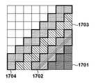
上記第5の実施形態では、一律にすべてのDCT係数を比較し、ローカルデコードをする/しないを切り替えたが、LDR画像の符号化条件であるQパラメータによって、比較するDCT係数の数およびTh_diffを切り替えてもよい。たとえば、Th_diffは比較するDCT係数の半数とすればよい。図17にDCT係数を模式的に示す。左上隅がDC成分であり、右下がAC成分であるとする。LDR画像のQパラメータが大きい場合は、図17の符号1701で示す、高周波側のDCT係数6個のみを比較する。逆にLDR画像のQパラメータが小さい場合は、図17の符号1701〜1704を合わせた43個のDCT係数を比較対象とする。
[Modified Example of Fifth Embodiment]
In the fifth embodiment, all DCT coefficients are uniformly compared and local decoding is switched on / off, but the number of DCT coefficients to be compared and Th_diff are determined by the Q parameter which is the coding condition of the LDR image. You may switch. For example, Th_diff may be half of the DCT coefficients to be compared. FIG. 17 schematically shows the DCT coefficient. It is assumed that the upper left corner is the DC component and the lower right is the AC component. When the Q parameter of the LDR image is large, only six DCT coefficients on the high frequency side shown by
本変形例の処理フローを図18に示す。なお、図16と同じ処理をするステップには、図16と同じ番号を付与し、その説明は省略する。 The processing flow of this modification is shown in FIG. The steps that perform the same processing as in FIG. 16 are given the same numbers as those in FIG. 16, and the description thereof will be omitted.
ステップS801にて、CPU201は、マクロブロック単位の線形LDR画像を作成する。ステップS307にて、CPU201は、ステップS801で作成した線形LDR画像の色変換を行う。ステップS1601にて、CPU201は、色変換後のLDR画像にDCTをかけ、その輝度の係数をメモリ206に保存する。ステップS1602にて、CPU201は、LDR画像のQパラメータに応じて、DCT係数の量子化を行う。ステップS309にて、CPU201はエントロピー符号化を行う。ステップS1801にて、CPU201は、LDR画像のQパラメータが10以上であるか判定する。10以上であれば、ステップS1802へ進む。10未満であれば、CPU201は、量子化による差異が大きい(量子化ステップが大きい)と判断し、ステップS1607へ処理を進め、ローカルデコード処理を実行する。ステップS1702にて、CPU201は、LDR画像のQパラメータが90未満であるか判定する。90未満であれば、CPU201はステップS1803へ処理を進める。また、90以上であれば、CPU201は、量子化による差異は小さいと判断し、ローカルデコードは行わず、この処理フローを終了する。ステップS1803にて、CPU201は、Qパラメータに応じた比較対象となるDCT係数の数と、しきい値Th_diffを取得する。本実施形態では以下のような値を取得するものとする。
(1) Qが70以上90未満の場合
比較対象のDCT係数は、図17の1701で示す6係数
Th_diff=3
(2) Qが50以上70未満の場合
比較対象のDCT係数は、図17の1701および1702で示す15係数
Th_diff=8
(3) Qが30以上50未満の場合
比較対象のDCT係数は、図17の1701〜1703で示す28係数
Th_diff=14
(4) Qが10以上30未満の場合
比較対象のDCT係数は、図17の1701〜1704で示す43係数
Th_diff=22
次に、CPU201は、処理をステップS1603に進める。このステップS1603以降は第5の実施形態と同様の処理であるので、ここでの説明は省略する。
In step S801, the
(1) When Q is 70 or more and less than 90 The DCT coefficient to be compared is the 6 coefficient Th_diff = 3 shown in 1701 in FIG.
(2) When Q is 50 or more and less than 70 The DCT coefficient to be compared is the 15 coefficient Th_diff = 8 shown in 1701 and 1702 in FIG.
(3) When Q is 30 or more and less than 50 The DCT coefficient to be compared is the 28 coefficient Th_diff = 14 shown in 1701 to 1703 in FIG.
(4) When Q is 10 or more and less than 30, the DCT coefficient to be compared is the 43 coefficient Th_diff = 22 shown in 1701 to 1704 in FIG.
Next, the
(その他の実施例)
本発明は、上述の実施形態の1以上の機能を実現するプログラムを、ネットワーク又は記憶媒体を介してシステム又は装置に供給し、そのシステム又は装置のコンピュータにおける1つ以上のプロセッサーがプログラムを読出し実行する処理でも実現可能である。また、1以上の機能を実現する回路(例えば、ASIC)によっても実現可能である。
(Other Examples)
The present invention supplies a program that realizes one or more functions of the above-described embodiment to a system or device via a network or storage medium, and one or more processors in the computer of the system or device reads and executes the program. It is also possible to realize the processing. It can also be realized by a circuit (for example, ASIC) that realizes one or more functions.
201…CPU、202…入力部、203…HDR補助データ生成部、204…LDR画像生成部、205…JPEGコーデック部、206…メモリ、207…表示部、208…蓄積部 201 ... CPU, 202 ... Input unit, 203 ... HDR auxiliary data generation unit, 204 ... LDR image generation unit, 205 ... JPEG codec unit, 206 ... Memory, 207 ... Display unit, 208 ... Storage unit
Claims (12)
符号化対象のHDR画像からLDR画像を生成するLDR画像生成手段と、
生成したLDR画像を非可逆符号化する符号化手段と、
符号化したLDR画像を復号する復号手段と、
HDR画像とLDR画像に基づき、LDR画像をHDR画像の精度に戻すための補助データを生成する補助データ生成手段と、
HDR画像における画素の輝度値に基づき、前記補助データ生成手段が利用するLDR画像として、前記LDR画像生成手段が生成したLDR画像、前記復号手段による復号で得たLDR画像のいずれを用いるかを判定する判定手段と
を有することを特徴とする画像符号化装置。 An image coding device that encodes an HDR image and generates auxiliary data for returning the LDR image to the accuracy of the HDR image.
An LDR image generation means for generating an LDR image from an HDR image to be encoded, and
A coding means for irreversibly coding the generated LDR image,
Decoding means for decoding the encoded LDR image,
Auxiliary data generation means for generating auxiliary data for returning the LDR image to the accuracy of the HDR image based on the HDR image and the LDR image, and
Based on the brightness value of the pixels in the HDR image, it is determined whether the LDR image used by the auxiliary data generation means is the LDR image generated by the LDR image generation means or the LDR image obtained by decoding by the decoding means. An image coding apparatus having a determination means for performing an image.
前記復号手段は、前記エントロピー符号化を行う前の係数に対して逆量子化、逆DCT、逆色変換を行う手段であることを特徴とする請求項1に記載の画像符号化装置。 The coding means is a JPEG codec means that performs color conversion, DCT conversion, quantization, and entropy coding in units of macroblocks.
The image coding apparatus according to claim 1, wherein the decoding means is a means for performing inverse quantization, inverse DCT, and inverse color conversion with respect to the coefficient before the entropy coding.
前記復号手段はマクロブロックを単位に復号し、
前記判定手段はマクロブロックが示す画像を単位に判定することを特徴とする請求項2に記載の画像符号化装置。 The LDR image generation means generates an LDR image in units of macroblocks, and generates an LDR image.
The decoding means decodes macroblocks in units.
The image coding apparatus according to claim 2, wherein the determination means determines an image indicated by a macroblock as a unit.
HDR画像における画素のうち、予め設定された輝度値より低い輝度を持つ画素が占める割合を求め、
当該割合が予め設定された閾値を超える場合、前記復号手段で得たLDR画像を前記補助データ生成手段により利用するものとして決定し、
前記割合が予め設定された閾値以下の場合、前記LDR画像生成手段で得たLDR画像を前記補助データ生成手段により利用するものとして決定することを特徴とする請求項1乃至3のいずれか1項に記載の画像符号化装置。 The determination means
Find the percentage of pixels in the HDR image that have a brightness lower than the preset brightness value.
When the ratio exceeds a preset threshold value, it is determined that the LDR image obtained by the decoding means is used by the auxiliary data generation means.
Any one of claims 1 to 3, wherein when the ratio is equal to or less than a preset threshold value, the LDR image obtained by the LDR image generation means is determined to be used by the auxiliary data generation means. The image encoding device according to.
前記判定手段は、
前記設定手段により符号化対象のHDR画像内の最大輝度、最小輝度に依存したトーンカーブを用いると設定された場合、前記復号手段で得たLDR画像を前記補助データ生成手段により利用するものとして決定し、
前記設定手段により前記固定のトーンカーブを用いると設定された場合、前記LDR画像生成手段で得たLDR画像を前記補助データ生成手段により利用するものとして決定する
ことを特徴とする請求項1乃至3のいずれか1項に記載の画像符号化装置。 Whether to use a preset fixed tone curve or a tone curve depending on the maximum brightness and the minimum brightness in the HDR image to be encoded is used as the tone curve used when the LDR image generation means generates. It also has a setting means to set
The determination means
When the setting means sets to use the tone curve depending on the maximum brightness and the minimum brightness in the HDR image to be encoded, it is determined that the LDR image obtained by the decoding means is used by the auxiliary data generation means. And
When the fixed tone curve is set to be used by the setting means, claims 1 to 3 are characterized in that the LDR image obtained by the LDR image generating means is determined to be used by the auxiliary data generating means. The image coding apparatus according to any one of the above.
前記判定手段は、
前記設定手段によりローカルトーンマッピングを利用すると設定された場合、前記復号手段で得たLDR画像を前記補助データ生成手段により利用するものとして決定し、
前記設定手段によりグローバルトーンマッピングを利用すると設定された場合、前記LDR画像生成手段で得たLDR画像を前記補助データ生成手段により利用するものとして決定する
ことを特徴とする請求項1乃至3のいずれか1項に記載の画像符号化装置。 Further, it has a setting means for setting whether to use global tone mapping or local tone mapping as tone mapping when the LDR image generation means generates.
The determination means
When it is set to use the local tone mapping by the setting means, it is determined that the LDR image obtained by the decoding means is used by the auxiliary data generation means.
Any of claims 1 to 3, wherein when the global tone mapping is set to be used by the setting means, the LDR image obtained by the LDR image generation means is determined to be used by the auxiliary data generation means. The image coding apparatus according to claim 1.
前記符号化手段における量子化で用いる量子化ステップが予め設定された値を超える場合、前記復号手段で得たLDR画像を前記補助データ生成手段により利用するものとして決定し、
前記符号化手段における量子化で用いる量子化ステップが前記予め設定された値以下である場合、前記LDR画像生成手段で得たLDR画像を前記補助データ生成手段により利用するものとして決定することを特徴とする請求項2又は3に記載の画像符号化装置。 The determination means
When the quantization step used in the quantization in the coding means exceeds a preset value, it is determined that the LDR image obtained by the decoding means is used by the auxiliary data generation means.
When the quantization step used in the quantization in the coding means is equal to or less than the preset value, the LDR image obtained by the LDR image generation means is determined to be used by the auxiliary data generation means. The image coding apparatus according to claim 2 or 3.
前記符号化手段における色変換による色差成分について間引きが存在する場合、前記復号手段で得たLDR画像を前記補助データ生成手段により利用するものとして決定し、
前記符号化手段における色変換による色差成分について間引きが存在しない場合、
前記LDR画像生成手段で得たLDR画像を前記補助データ生成手段により利用するもの
として決定することを特徴とする請求項2又は3に記載の画像符号化装置。 The determination means
When the color difference component due to the color conversion in the coding means is thinned out, the LDR image obtained by the decoding means is determined to be used by the auxiliary data generation means.
When there is no thinning out for the color difference component due to the color conversion in the coding means,
The image coding apparatus according to claim 2 or 3, wherein the LDR image obtained by the LDR image generation means is determined to be used by the auxiliary data generation means.
前記DCT変換を行って得た係数と、前記復号手段による逆量子化後の係数との差分を求め、当該差分の絶対値が予め設定した値を超える個数の占める割合と、予め設定された閾値とを比較し、
前記割合が前記閾値より大きい場合、前記復号手段で得たLDR画像を前記補助データ生成手段により利用するものとして決定し、
前記割合が前記閾値以下の場合、前記LDR画像生成手段で得たLDR画像を前記補助データ生成手段により利用するものとして決定する
ことを特徴とする請求項2又は3に記載の画像符号化装置。 The determination means
The difference between the coefficient obtained by performing the DCT transform and the coefficient after inverse quantization by the decoding means is obtained, and the ratio of the number of absolute values exceeding the preset value and the preset threshold value. Compare with
When the ratio is larger than the threshold value, the LDR image obtained by the decoding means is determined to be used by the auxiliary data generation means.
The image coding apparatus according to claim 2 or 3, wherein when the ratio is equal to or less than the threshold value, the LDR image obtained by the LDR image generation means is determined to be used by the auxiliary data generation means.
符号化対象のHDR画像からLDR画像を生成するLDR画像生成工程と、
生成したLDR画像を非可逆符号化する符号化工程と、
符号化したLDR画像を復号する復号工程と、
HDR画像とLDR画像に基づき、LDR画像をHDR画像の精度に戻すための補助データを生成する補助データ生成工程と、
HDR画像における画素の輝度値に基づき、前記補助データ生成工程が利用するLDR画像として、前記LDR画像生成工程が生成したLDR画像、前記復号工程による復号で得たLDR画像のいずれを用いるかを判定する判定工程と
を有することを特徴とする画像符号化装置の制御方法。 It is a control method of an image encoding device that encodes an HDR image and generates auxiliary data for returning the LDR image to the accuracy of the HDR image.
An LDR image generation step of generating an LDR image from an HDR image to be encoded, and
A coding step that irreversibly encodes the generated LDR image,
A decoding process that decodes the encoded LDR image, and
Auxiliary data generation process for generating auxiliary data for returning the LDR image to the accuracy of the HDR image based on the HDR image and the LDR image, and
Based on the brightness value of the pixels in the HDR image, it is determined whether the LDR image used by the auxiliary data generation step is the LDR image generated by the LDR image generation step or the LDR image obtained by decoding by the decoding step. A method for controlling an image coding apparatus, which comprises a determination step for performing an image.
Priority Applications (1)
| Application Number | Priority Date | Filing Date | Title |
|---|---|---|---|
| JP2016203813A JP6867774B2 (en) | 2016-10-17 | 2016-10-17 | Image coding device and its control method |
Applications Claiming Priority (1)
| Application Number | Priority Date | Filing Date | Title |
|---|---|---|---|
| JP2016203813A JP6867774B2 (en) | 2016-10-17 | 2016-10-17 | Image coding device and its control method |
Publications (3)
| Publication Number | Publication Date |
|---|---|
| JP2018067758A JP2018067758A (en) | 2018-04-26 |
| JP2018067758A5 JP2018067758A5 (en) | 2019-11-14 |
| JP6867774B2 true JP6867774B2 (en) | 2021-05-12 |
Family
ID=62087372
Family Applications (1)
| Application Number | Title | Priority Date | Filing Date |
|---|---|---|---|
| JP2016203813A Active JP6867774B2 (en) | 2016-10-17 | 2016-10-17 | Image coding device and its control method |
Country Status (1)
| Country | Link |
|---|---|
| JP (1) | JP6867774B2 (en) |
Families Citing this family (1)
| Publication number | Priority date | Publication date | Assignee | Title |
|---|---|---|---|---|
| JP7129326B2 (en) * | 2018-12-14 | 2022-09-01 | キヤノン株式会社 | IMAGING DEVICE, CONTROL METHOD AND PROGRAM THEREOF |
Family Cites Families (3)
| Publication number | Priority date | Publication date | Assignee | Title |
|---|---|---|---|---|
| US8175158B2 (en) * | 2008-01-04 | 2012-05-08 | Sharp Laboratories Of America, Inc. | Methods and systems for inter-layer image prediction parameter determination |
| JP6174926B2 (en) * | 2013-07-11 | 2017-08-02 | キヤノン株式会社 | Image decoding apparatus and control method thereof |
| JP2015019286A (en) * | 2013-07-11 | 2015-01-29 | キヤノン株式会社 | Image encoder and decoder and control method of these, and image processing system |
-
2016
- 2016-10-17 JP JP2016203813A patent/JP6867774B2/en active Active
Also Published As
| Publication number | Publication date |
|---|---|
| JP2018067758A (en) | 2018-04-26 |
Similar Documents
| Publication | Publication Date | Title |
|---|---|---|
| AU2014213524B2 (en) | High dynamic range image generation and rendering | |
| JP4979655B2 (en) | Image coding apparatus and control method thereof | |
| US9602842B2 (en) | Encoding apparatus and method of controlling the same | |
| US20080267495A1 (en) | Image compressing method and image compressing apparatus | |
| US9300840B2 (en) | Image processing device and computer-readable storage medium storing computer-readable instructions | |
| EP3054683A1 (en) | Image coding device, image decoding device, and programs therefor | |
| KR102475139B1 (en) | Method for tone adapting an image to a target peak luminance lt of a target display device | |
| US20160360231A1 (en) | Efficient still image coding with video compression techniques | |
| JP6867774B2 (en) | Image coding device and its control method | |
| CN114467298B (en) | Image signal conversion processing method and device and terminal equipment | |
| EP0833518A2 (en) | Compression of image data with associated cost data | |
| JP6866224B2 (en) | Image coding device, image decoding device, image coding method and program | |
| JP4756949B2 (en) | Image decoding apparatus, control method therefor, computer program, and computer-readable storage medium | |
| JPH0487460A (en) | Picture processor | |
| JP6637711B2 (en) | Encoding device and its control method, program, and storage medium | |
| JP2020092327A (en) | Image encoding device, image encoding method, and program | |
| US10462478B2 (en) | Method of video generation | |
| US20110103705A1 (en) | Image encoding method and apparatus, and image decoding method and apparatus | |
| JP6838951B2 (en) | Coding device and coding method | |
| JP6936699B2 (en) | Image coding device and its control method and program | |
| JP6985899B2 (en) | Image coding device and its control method and program | |
| JP2009111821A (en) | Image encoding apparatus, image decoding apparatus, image data processing apparatus, image encoding method, and image decoding method | |
| JP2006340338A (en) | Image processor | |
| JP2023136246A (en) | Image processing apparatus, control method and program | |
| JPH04180356A (en) | Image encoding method |
Legal Events
| Date | Code | Title | Description |
|---|---|---|---|
| A521 | Written amendment |
Free format text: JAPANESE INTERMEDIATE CODE: A523 Effective date: 20191004 |
|
| A621 | Written request for application examination |
Free format text: JAPANESE INTERMEDIATE CODE: A621 Effective date: 20191004 |
|
| A977 | Report on retrieval |
Free format text: JAPANESE INTERMEDIATE CODE: A971007 Effective date: 20201215 |
|
| A131 | Notification of reasons for refusal |
Free format text: JAPANESE INTERMEDIATE CODE: A131 Effective date: 20210104 |
|
| RD01 | Notification of change of attorney |
Free format text: JAPANESE INTERMEDIATE CODE: A7421 Effective date: 20210103 |
|
| A521 | Written amendment |
Free format text: JAPANESE INTERMEDIATE CODE: A523 Effective date: 20210113 |
|
| A521 | Written amendment |
Free format text: JAPANESE INTERMEDIATE CODE: A523 Effective date: 20210302 |
|
| TRDD | Decision of grant or rejection written | ||
| A01 | Written decision to grant a patent or to grant a registration (utility model) |
Free format text: JAPANESE INTERMEDIATE CODE: A01 Effective date: 20210312 |
|
| A61 | First payment of annual fees (during grant procedure) |
Free format text: JAPANESE INTERMEDIATE CODE: A61 Effective date: 20210409 |
|
| R151 | Written notification of patent or utility model registration |
Ref document number: 6867774 Country of ref document: JP Free format text: JAPANESE INTERMEDIATE CODE: R151 |