JP6866068B2 - Lighting equipment, its control method, and control program, and imaging equipment - Google Patents
Lighting equipment, its control method, and control program, and imaging equipment Download PDFInfo
- Publication number
- JP6866068B2 JP6866068B2 JP2016041116A JP2016041116A JP6866068B2 JP 6866068 B2 JP6866068 B2 JP 6866068B2 JP 2016041116 A JP2016041116 A JP 2016041116A JP 2016041116 A JP2016041116 A JP 2016041116A JP 6866068 B2 JP6866068 B2 JP 6866068B2
- Authority
- JP
- Japan
- Prior art keywords
- light emission
- strobe
- light emitting
- control
- microcomputer
- Prior art date
- Legal status (The legal status is an assumption and is not a legal conclusion. Google has not performed a legal analysis and makes no representation as to the accuracy of the status listed.)
- Active
Links
Images


Classifications
-
- H—ELECTRICITY
- H04—ELECTRIC COMMUNICATION TECHNIQUE
- H04N—PICTORIAL COMMUNICATION, e.g. TELEVISION
- H04N23/00—Cameras or camera modules comprising electronic image sensors; Control thereof
- H04N23/70—Circuitry for compensating brightness variation in the scene
-
- H—ELECTRICITY
- H05—ELECTRIC TECHNIQUES NOT OTHERWISE PROVIDED FOR
- H05B—ELECTRIC HEATING; ELECTRIC LIGHT SOURCES NOT OTHERWISE PROVIDED FOR; CIRCUIT ARRANGEMENTS FOR ELECTRIC LIGHT SOURCES, IN GENERAL
- H05B41/00—Circuit arrangements or apparatus for igniting or operating discharge lamps
- H05B41/14—Circuit arrangements
- H05B41/30—Circuit arrangements in which the lamp is fed by pulses, e.g. flash lamp
- H05B41/32—Circuit arrangements in which the lamp is fed by pulses, e.g. flash lamp for single flash operation
- H05B41/325—Circuit arrangements in which the lamp is fed by pulses, e.g. flash lamp for single flash operation by measuring the incident light
-
- G—PHYSICS
- G03—PHOTOGRAPHY; CINEMATOGRAPHY; ANALOGOUS TECHNIQUES USING WAVES OTHER THAN OPTICAL WAVES; ELECTROGRAPHY; HOLOGRAPHY
- G03B—APPARATUS OR ARRANGEMENTS FOR TAKING PHOTOGRAPHS OR FOR PROJECTING OR VIEWING THEM; APPARATUS OR ARRANGEMENTS EMPLOYING ANALOGOUS TECHNIQUES USING WAVES OTHER THAN OPTICAL WAVES; ACCESSORIES THEREFOR
- G03B15/00—Special procedures for taking photographs; Apparatus therefor
- G03B15/02—Illuminating scene
- G03B15/03—Combinations of cameras with lighting apparatus; Flash units
- G03B15/05—Combinations of cameras with electronic flash apparatus; Electronic flash units
-
- H—ELECTRICITY
- H04—ELECTRIC COMMUNICATION TECHNIQUE
- H04N—PICTORIAL COMMUNICATION, e.g. TELEVISION
- H04N23/00—Cameras or camera modules comprising electronic image sensors; Control thereof
- H04N23/56—Cameras or camera modules comprising electronic image sensors; Control thereof provided with illuminating means
-
- H—ELECTRICITY
- H04—ELECTRIC COMMUNICATION TECHNIQUE
- H04N—PICTORIAL COMMUNICATION, e.g. TELEVISION
- H04N23/00—Cameras or camera modules comprising electronic image sensors; Control thereof
- H04N23/70—Circuitry for compensating brightness variation in the scene
- H04N23/75—Circuitry for compensating brightness variation in the scene by influencing optical camera components
-
- H—ELECTRICITY
- H05—ELECTRIC TECHNIQUES NOT OTHERWISE PROVIDED FOR
- H05B—ELECTRIC HEATING; ELECTRIC LIGHT SOURCES NOT OTHERWISE PROVIDED FOR; CIRCUIT ARRANGEMENTS FOR ELECTRIC LIGHT SOURCES, IN GENERAL
- H05B41/00—Circuit arrangements or apparatus for igniting or operating discharge lamps
- H05B41/14—Circuit arrangements
- H05B41/36—Controlling
- H05B41/38—Controlling the intensity of light
- H05B41/39—Controlling the intensity of light continuously
-
- H—ELECTRICITY
- H05—ELECTRIC TECHNIQUES NOT OTHERWISE PROVIDED FOR
- H05B—ELECTRIC HEATING; ELECTRIC LIGHT SOURCES NOT OTHERWISE PROVIDED FOR; CIRCUIT ARRANGEMENTS FOR ELECTRIC LIGHT SOURCES, IN GENERAL
- H05B47/00—Circuit arrangements for operating light sources in general, i.e. where the type of light source is not relevant
- H05B47/10—Controlling the light source
- H05B47/105—Controlling the light source in response to determined parameters
- H05B47/115—Controlling the light source in response to determined parameters by determining the presence or movement of objects or living beings
- H05B47/125—Controlling the light source in response to determined parameters by determining the presence or movement of objects or living beings by using cameras
-
- G—PHYSICS
- G03—PHOTOGRAPHY; CINEMATOGRAPHY; ANALOGOUS TECHNIQUES USING WAVES OTHER THAN OPTICAL WAVES; ELECTROGRAPHY; HOLOGRAPHY
- G03B—APPARATUS OR ARRANGEMENTS FOR TAKING PHOTOGRAPHS OR FOR PROJECTING OR VIEWING THEM; APPARATUS OR ARRANGEMENTS EMPLOYING ANALOGOUS TECHNIQUES USING WAVES OTHER THAN OPTICAL WAVES; ACCESSORIES THEREFOR
- G03B2215/00—Special procedures for taking photographs; Apparatus therefor
- G03B2215/05—Combinations of cameras with electronic flash units
- G03B2215/0589—Diffusors, filters or refraction means
- G03B2215/0592—Diffusors, filters or refraction means installed in front of light emitter
-
- Y—GENERAL TAGGING OF NEW TECHNOLOGICAL DEVELOPMENTS; GENERAL TAGGING OF CROSS-SECTIONAL TECHNOLOGIES SPANNING OVER SEVERAL SECTIONS OF THE IPC; TECHNICAL SUBJECTS COVERED BY FORMER USPC CROSS-REFERENCE ART COLLECTIONS [XRACs] AND DIGESTS
- Y02—TECHNOLOGIES OR APPLICATIONS FOR MITIGATION OR ADAPTATION AGAINST CLIMATE CHANGE
- Y02B—CLIMATE CHANGE MITIGATION TECHNOLOGIES RELATED TO BUILDINGS, e.g. HOUSING, HOUSE APPLIANCES OR RELATED END-USER APPLICATIONS
- Y02B20/00—Energy efficient lighting technologies, e.g. halogen lamps or gas discharge lamps
- Y02B20/40—Control techniques providing energy savings, e.g. smart controller or presence detection
Description
本発明は、照明装置、その制御方法、および制御プログラム、並びに撮像装置に関し、特に、光学アクセサリを装着可能な照明装置に関する。 The present invention relates to a lighting device, a control method thereof, a control program, and an imaging device, and more particularly to a lighting device to which an optical accessory can be attached.
一般に、デジタルカメラなどの撮像装置で用いられるストロボ装置などの照明装置では、発光に伴う発熱により照明装置の温度が上昇しユーザに不快感を与えることを防止するため、発光に制限が設定されている。一方、発光に制限を設けると、撮影中に急に発光を行うことができなくなるなど照明装置の発光可能なタイミングが制限されてしまう。 Generally, in a lighting device such as a strobe device used in an imaging device such as a digital camera, a limit is set for light emission in order to prevent the temperature of the lighting device from rising due to heat generated by light emission and causing discomfort to the user. There is. On the other hand, if the light emission is limited, the timing at which the lighting device can emit light is limited, for example, it becomes impossible to suddenly emit light during shooting.
このような問題に対処するため、発光条件に応じてカウント値を加算する発光カウンタを備えて、発光カウンタのカウント値が所定のカウント値となると発光を制限するようにしたものがある(特許文献1参照)。 In order to deal with such a problem, there is a light emitting counter that adds a count value according to a light emitting condition so as to limit light emission when the count value of the light emitting counter reaches a predetermined count value (Patent Document). 1).
デジタルカメラなどの撮像装置とともに用いられる照明装置においては、その発光部に光の色を調整するためのカラーフィルタが装着可能なものがある。また、光を天井又は壁などに向けて照射し、その拡散反射光を被写体に照射する発光撮影(所謂バウンス発光撮影)の際、広範囲に光を拡散させて被写体の影を抑えるバウンス効果を高めるバウンスアダプタが装着可能な照明装置がある。さらには、被写体に対する直接光を和らげて自然なライティングとするためディフューザが装着可能な照明装置がある。このように、照明装置には様々な光学アクセサリが装着されて、撮影の際に利用されている。これらの光学アクセサリを装着している状態は、光学アクセサリを装着していない状態よりも発光に伴う発熱により照明装置の温度が上昇しやすい。しかしながら、特許文献1では、光学アクセサリを装着している状態についてなんら考慮されていない。
In some lighting devices used together with an imaging device such as a digital camera, a color filter for adjusting the color of light can be attached to the light emitting portion. In addition, during luminescence photography (so-called bounce luminescence photography) in which light is emitted toward the ceiling or wall and the diffusely reflected light is applied to the subject, the light is diffused over a wide range to enhance the bounce effect of suppressing the shadow of the subject. There is a lighting device to which a bounce adapter can be attached. Furthermore, there is a lighting device to which a diffuser can be attached in order to soften the direct light to the subject and make the lighting natural. In this way, various optical accessories are attached to the lighting device and are used for shooting. When these optical accessories are attached, the temperature of the lighting device is more likely to rise due to heat generated by light emission than when the optical accessories are not attached. However,
そこで、本発明の目的は、光学アクセサリの有無にかかわらず、照明装置の温度上昇を抑制しながら、良好な発光制御を行うことができる照明装置、その制御方法、および制御プログラム、並びに撮像装置を提供することにある。 Therefore, an object of the present invention is to provide a lighting device, a control method thereof, a control program, and an imaging device capable of performing good light emission control while suppressing a temperature rise of the lighting device regardless of the presence or absence of an optical accessory. To provide.
上記の目的を達成するため、本発明による照明装置は、発光手段と、前記発光手段に調色又は配光角調整のための光学アクセサリが装着されたか否かを検知する検知手段と、前記検知手段による検知結果に基づいて、前記光学アクセサリが装着されている場合は前記光学アクセサリが装着されていない場合よりも、前記発光手段の最短発光間隔が長くなるように制御する制御手段と、を有し、前記発光手段は、前記発光手段の発光によって温度上昇する対象部位との相対位置を変更可能に保持されていて、前記制御手段は、前記発光手段と前記対象部位との相対位置に基づいて前記最短発光間隔を制御することを特徴とする。 In order to achieve the above object, the lighting device according to the present invention includes a light emitting means, a detecting means for detecting whether or not an optical accessory for color matching or light distribution angle adjustment is attached to the light emitting means, and the detection. based on the detection result by the means, have a, and control means for controlling so that the shortest light emission interval is longer in the than the optical accessory is not mounted, the light emitting means when the optical accessory is mounted The light emitting means is held so that the relative position with respect to the target portion whose temperature rises due to the light emission of the light emitting means can be changed, and the control means is based on the relative position between the light emitting means and the target portion. It is characterized in that the shortest light emission interval is controlled.
本発明によれば、光学アクセサリの有無にかかわらず、照明装置の温度上昇を抑制しながら、良好な発光制御を行うことができる。 According to the present invention, good light emission control can be performed while suppressing the temperature rise of the lighting device regardless of the presence or absence of the optical accessory.
以下に、本発明の実施の形態による照明装置の一例について図面を参照して説明する。 Hereinafter, an example of the lighting device according to the embodiment of the present invention will be described with reference to the drawings.
[第1の実施形態]
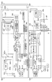
図1は、本発明の第1の実施形態による照明装置を備える撮像装置の一例についてその構成を示す図である。また、図2は、図1に示す撮像装置について一部を破断してその構成を示す図である。
[First Embodiment]
FIG. 1 is a diagram showing the configuration of an example of an image pickup apparatus including the illumination apparatus according to the first embodiment of the present invention. Further, FIG. 2 is a diagram showing the configuration of the image pickup apparatus shown in FIG. 1 by breaking a part thereof.
図1および図2を参照して、図示の撮像装置は、例えば、デジタルカメラ(以下単にカメラと呼ぶ)であり、当該カメラはカメラ本体100を有している。カメラ本体100には交換可能な撮影レンズユニット(以下単に撮影レンズと呼ぶ:撮像光学系)200が装着されている。さらに、カメラ本体100には着脱可能なストロボ装置300などの発光装置が取り付けられている。なお、ストロボ装置(以下単にストロボと呼ぶ)300には、着脱可能に光学アクセサリ500が装着されている。
With reference to FIGS. 1 and 2, the illustrated imaging device is, for example, a digital camera (hereinafter simply referred to as a camera), and the camera has a
カメラ100には、マイクロコンピュータ(CCPU:以下カメラマイコンと呼ぶ)101が備えられており、カメラマイコン101はカメラ全体の制御を司る。カメラマイコン101はマイコン内蔵ワンチップIC回路である。カメラマイコン101はCPU、ROM、RAM、入出力制御回路(I/Oコントロール回路)、マルチプレクサ、タイマー回路、EEPROM、A/Dコンバータ、およびD/Aコンバータなどを有している。そして、カメラマイコン101は、プログラム(つまり、ソフトウェア)によってカメラ本体、撮影レンズ200、およびストロボ300の制御を行うとともに、各種の条件判定を行う。
The
撮像素子102は赤外カットフィルタおよびローパスフィルタなどを備えるCCD又はCMOSセンサである。そして、撮像素子102には後述するレンズ群202を介して光学像(被写体像)が結像して、撮像素子102は光学像に応じた電気信号(アナログ信号)を出力する。
The
シャッター103は非撮影の際には撮像素子102を遮光して、撮影の際にはシャッター幕を開いて撮像素子102に光学像を導く。主ミラー(ハーフミラー)104は非撮影の際にはレンズ群202を介して入射する光を反射してピント板105に結像させる。撮影者はピント板105に投影された像をアイピース120によって目視で確認する。
The
測光回路(AE)106は測光センサーを備えており、ここでは、測光センサーとして複数の画素を備えるCCD又はCMOSセンサーなどの撮像素子が用いられる。記録用画像の取得前に、測光回路106において得た画像を後述するデジタル信号処理回路111によって解析して被写体の顔の向きなどが検出される。なお、測光センサーにはペンタプリズム114を介してピント板105に結像した被写体像が入射する。
The photometric circuit (AE) 106 includes a photometric sensor, and here, an image pickup element such as a CCD or CMOS sensor having a plurality of pixels is used as the photometric sensor. Before acquiring the image for recording, the image obtained by the
焦点検出回路(AF)107は測距センサーを備えており、当該測距センサーは複数点を測距ポイントとして、測距ポイント毎のデフォーカス量を示す焦点情報を出力する。なお、測光センサーは複数の領域に分割されており、当該領域には測距ポイントが含まれている。 The focus detection circuit (AF) 107 includes a range-finding sensor, and the range-finding sensor outputs focus information indicating the amount of defocus for each range-finding point, with a plurality of points as the range-finding points. The photometric sensor is divided into a plurality of areas, and the area includes a distance measuring point.
ゲイン切り換え回路108は撮像素子102の出力である電気信号を増幅するゲインを切換えるための回路である。ゲイン切り換え回路108は、カメラマイコン101の制御下で撮影の条件および撮影者の指示などに応じてゲイン切り換えを行う。A/D変換器109は撮像素子102の出力である電気信号をデジタル信号に変換する。タイミングジェネレータ(TG)110は撮像素子102の出力である電気信号とA/D変換器109によるA/D変換のタイミングとを同期させる。
The
デジタル信号処理回路(単に信号処理回路ともいう)111はA/D変換器109の出力であるデジタル信号について所定の現像パラメータに応じて画像処理を行って画像データを生成する。なお、ここでは、処理画像に用いられるメモリなどは省略されている。
The digital signal processing circuit (also simply referred to as a signal processing circuit) 111 performs image processing on the digital signal output from the A /
入力部112は、電源スイッチ、レリーズスイッチ、および設定ボタンなどを備える操作部を有し、カメラマイコン101は入力部112の入力に応じて各種処理を行う。レリーズスイッチが1段階操作(半押し)されると、第1のレリーズスイッチSW1がONとなって、カメラマイコン101は焦点調節および測光などの撮影準備動作を開始する。また、レリーズスイッチが2段階操作(全押し)されると、第2のレリーズスイッチSW2がONとなって、カメラマイコン101は露光および現像処理などの撮影動作を開始する。さらに、入力部112に備えられた設定ボタンを操作することによって、ストロボ300の各種設定を行うことができる。
The
表示部113には設定されたカメラの撮影モード、その他の撮影情報などが表示される。なお、表示部113は、例えば、液晶表示装置および発光素子などを有している。
The
ペンタプリズム114はピント板105に結像した被写体像を測光回路106に備えられた測光センサーに導くとともにアイピース120に導く。サブミラー115は主ミラー104を透過した光を焦点検出回路107に備えられた測距センサーに導く。
The
通信ラインLCおよびSCはそれぞれカメラ本体100と撮影レンズ200およびストロボ300とのインタフェースである。例えば、カメラマイコン101をホストとして、カメラ本体100、撮影レンズ200、およびストロボ300はデータの交換およびコマンドの伝達を相互に行う。例えば、図1に示すように、通信ラインLCおよびSCはそれぞれ端子120および130を有している。そして、端子120は、SCLK_L端子、MOSI_L端子、MISO_L端子、およびGND端子を備えている。
The communication lines LC and SC are interfaces between the
SCLK_L端子はカメラ本体100と撮影レンズ(レンズユニットともいう)200との通信を同期させるための端子である。MOSI_L端子はカメラ本体100からレンズユニット200にデータを送信するための端子である。MISO_L端子はレンズユニット200からカメラ本体100に送信されたデータを受信するための端子である。そして、GND端子にはカメラ本体100およびレンズユニット200が接続される。
The SCLK_L terminal is a terminal for synchronizing communication between the
端子130はSCLK_S端子、MOSI_S端子、MISO_S端子、およびGND端子を備えている。SCLK_S端子はカメラ本体100とストロボ300との通信を同期させるための端子である。MOSI_S端子はカメラ本体100からストロボ300にデータを送信するための端子である。MISO_S端子はストロボ300からカメラ本体100に送信されたデータを受信するための端子である。そして、GND端子にはカメラ本体100およびストロボ300が接続される。
The terminal 130 includes an SCLK_S terminal, a MOSI_S terminal, a MISO_S terminal, and a GND terminal. The SCLK_S terminal is a terminal for synchronizing the communication between the
撮影レンズ200は、マイクロコンピュータ(LPU:レンズマイコン)201を有している。レンズマイコン201は撮影レンズ200全体の制御を司る。レンズマイコン201は、例えば、CPU、ROM、RAM、入出力制御回路、マルチプレクサ、タイマー回路、EEPROM、A/Dコンバータ、およびD/Aコンバータを有するマイコン内蔵ワンチップIC回路である。
The photographing
撮影レンズ200は複数枚のレンズを有するレンズ群202を備えており、当該レンズ群202には少なくともフォーカスレンズが含まれている。レンズ駆動部203はレンズ群202において少なくともフォーカスレンズを光軸に沿って移動させる。カメラマイコン101は焦点検出回路107の検出出力に基づいて、レンズ群202を駆動する際の駆動量を算出して、レンズマイコン201に送る。
The photographing
エンコーダ204はレンズ群202を駆動した際、レンズ群202の位置を検出するためのものである。レンズマイコン201は、カメラマイコン101で算出された駆動量に応じてレンズ駆動部203を制御する。そして、レンズマイコン201はエンコーダ204の出力が示す位置を参照してレンズ群202を駆動制御して焦点調節を行う。絞り制御回路206は、レンズマイコン201の制御下で絞り205を制御する。
The
ストロボ300は、カメラ本体100に着脱可能に装着される本体部300aと、当該本体部300aに上下方向および左右方向に回動可能に保持される発光部300bとを有している。なお、以下の説明では、本体部300aにおいて発光部300bと連結される側を上側として発光部300bの回動方向を説明する。
The
ストロボ300は、マイクロコンピュータ(FPU:ストロボマイコン)310を備えており、ストロボマイコン310はストロボ300全体の制御を司る。ストロボマイコン310は、例えば、CPU、ROM、RAM、入出力制御回路、マルチプレクサ、タイマー回路、EEPROM、A/D、およびD/Aコンバータを有するマイコン内蔵ワンチップIC回路である。
The
電池301はストロボ300の電源(VBAT)であり、昇圧回路302は、昇圧部302a、電圧検出に用いる抵抗302bおよび302c、およびメインコンデンサ302dを有している。昇圧回路302は昇圧部302aによって電池301の電圧を数百Vに昇圧して、メインコンデンサ302dに発光のための電気エネルギーを蓄積する。メインコンデンサ302dの充電電圧は抵抗302bおよび302cによって分圧されて、当該分圧された電圧はストロボマイコン310のA/D変換端子に入力される。
The
放電管305は、トリガー回路303から印加される数KVのパルス電圧を受けてメインコンデンサ302dに充電されたエネルギーによって励起して発光する。そして、放電管305の光は被写体などに照射される。なお、発光制御回路304は放電管305の発光開始および発光停止を制御する。
The
フォトダイオード314は放電管305から光を受光して、その発光量に応じた検知出力(電流)を出力する。フォトダイオード314は直接又はグラスファイバーなどを介して放電管305の光を受光する。積分回路309はフォトダイオード314の出力である電流を積分する。そして、積分回路309の出力(積分出力)はコンパレータ315の非反転入力端子およびストロボマイコン310のA/Dコンバータ端子に入力される。
The
コンパレータ315の非反転入力端子はストロボマイコン310のD/Aコンバータ出力端子に接続され、コンパレータ315の出力端子はANDゲート311の入力端子の一方に接続される。ANDゲート311の入力端子の他方はストロボマイコン310の発光制御端子と接続され、ANDゲート311の出力端子は発光制御回路304に接続される。
The non-inverting input terminal of the
ストロボ300には、反射傘ユニット306aおよびズーム光学系が備えられており、反射傘306は放電管305から発せられた光を反射させて所定の方向に導く。ズーム光学系は光学パネル307などを備えている。ズーム光学系はストロボ300による光の照射角を変更する。反射傘ユニット306aと光学パネル307との相対的位置(相対位置)を変更することによって、ストロボ300のガイドナンバーおよび照射範囲を変化させることができる。つまり、光学パネル307と発光部300bとの相対位置は変更可能である。
The
発光部300bは、放電管305、反射傘306、および光学パネル307を備えており、発光部300bの配光角は反射傘ユニット306aの移動に応じて変化し、発光部300bの照射方向は本体部300aに対する回動によって変化する。
The
入力部312は、電源スイッチ、ストロボ300の動作モードを設定するモード設定スイッチ、および各種パラメータを設定する設定ボタンなど備える操作部を有している。そして、ストロボマイコン310は、入力部312の入力に応じて各種処理を行う。表示部313にはストロボ300の状態を示す情報が表示される。なお、表示部313には液晶装置および発光素子が備えられている。
The
ズーム駆動回路330は、ズーム検出部330aおよびズーム駆動部330bを備えている。ズーム検出部330aはエンコーダなどによって反射傘ユニット306aと光学パネル307との相対的位置を検出する。ズーム駆動部330bはモーターによって反射傘ユニット306aを移動させる。ストロボマイコン310は、レンズマイコン201からカメラマイコン101を介して焦点距離を得て、当該焦点距離に応じて反射傘ユニット306aの駆動量を求める。
The
アクセサリ検知部370は、例えば、調色又は配光角調整のための光学アクセサリ500の装着の有無を検知するスイッチである。アクセサリ検知部370は装着の有無を示すON−OFF情報(検知結果)をストロボマイコン310に送る。なお、複数の光学アクセサリを同時に装着することができ、光学アクセサリの数に対応してアクセサリ検知部が備えられる。また、アクセサリ検知部はスイッチに限らず、既知のセンサを用いるようにしてもよい。
The
光学アクセサリ500は、例えば、カラーフィルタ、バウンスアダプタ、又はディフューザなどであり、発光部300bの光学パネル面に装着される。そして、光学アクセサリ500はストロボ光の調色、拡散、又は配光角の変更などを行って、撮影の際のライティング効果を向上させる。光学アクセサリ500にはアクセサリ検知部370と相対する位置に突起が設けられ、当該突起がアクセサリ検知部370を押すことによって装着が検知される。
The
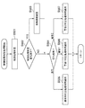
図3は、図1に示すストロボ300の発光処理を説明するためのフローチャートである。
FIG. 3 is a flowchart for explaining the light emission processing of the
入力部312に備えられた電源スイッチがオンされてストロボマイコン310が動作可能となると、ストロボマイコン310は、図3に示すフローチャートを開始する。
When the power switch provided in the
ます、ストロボマイコン310は、ストロボマイコンに備えられたメモリおよびポートを初期化する(ステップS301)。この際、ストロボマイコン310は入力部312に備えられたスイッチの状態および予め設定された入力情報を読み込んで、発光量の決定方法および発光タイミングなどの発光モードの設定を行う。
First, the
続いて、ストロボマイコン310は、昇圧回路302を制御してメインコンデンサ302dの充電を開始する(ステップS302)。メインコンデンサ302dの充電を開始した後、ストロボマイコン310は、アクセサリ検知部370によるアクセサリ検知情報を内蔵メモリに格納する(ステップS303)。なお、以前にアクセサリ検知情報が格納されている場合には、ストロボマイコン310はアクセサリ検知情報を更新する。
Subsequently, the
ストロボマイコン310は、カメラマイコン101から通信ラインSCを介して得た焦点距離情報を内蔵メモリに格納する(ステップS304)。なお、以前に焦点距離情報が格納されている場合には、ストロボマイコン310は焦点距離情報を更新する。
The
ストロボマイコン310は、ストロボ光の配光角が焦点距離情報に応じた範囲となるように、ズーム駆動回路330によって反射傘ユニット306aを移動する(ステップS305)。なお、反射傘ユニット306aを移動させる必要がない場合には、ステップS305の処理は省略される。続いて、ストロボマイコン310は、入力部312において設定された発光モードおよび焦点距離情報に関する情報を表示部313に表示する(ステップS306)。
The
ストロボマイコン310は、メインコンデンサ302dに充電が完了しているか否かを判定する(ステップS307)。充電が完了していないと(ステップS307において、NO)、ストロボマイコン310は待機する。一方、充電が完了すると(ステップS307において、YES)、ストロボマイコン310は充電完了信号をカメラマイコン101に送信して、ステップS308の処理に進む。
The
トロボマイコン310は、カメラマイコン101から本発光指示である本発光開始信号を受信したか否かを判定する(ステップS308)。本発光開始信号を受信しないと(ステップS308において、NO)、ストロボマイコン310はステップS302の処理に戻る。一方、本発光開始信号を受信すると(ステップS308において、YES)、ストロボマイコン310は本発光開始信号に応じて発光制御回路304を制御して放電管305を本発光させる(ステップS309)。本発光終了の後、ストロボマイコン310はメインコンデンサ302dの電圧などの発光に関する情報を内蔵メモリに格納して、ステップS310の処理に進む。
The
ストロボマイコン310は、連続発光などによってストロボ300が温度上昇しすぎないように発光および充電を制御する連続発光制御を開始する(ステップS310)。なお、連続発光制御については後述する。
The
この連続発光制御は初期状態から変化が生じた場合に行われ、初期状態に戻ると終了する。ここでは、ストロボマイコン310は発光によって発生する熱の影響を考慮する必要がある対象部位の温度を想定する。そして、ストロボマイコン310は、1回目の発光から対象部位の想定温度を求めるか又は想定温度の代替であるカウンタのカウントを開始する。そして、ストロボマイコン310は想定温度が初期状態と同一となるまで又はカウンタがリセットされるまで、図3に示す発光処理と並行して連続発光制御を行う。なお、当該連続発光制御は単発の発光についても同様にして行われる。連続発光制御を開始した後、ストロボマイコン310は発光処理をステップS302の処理に戻す。
This continuous light emission control is performed when a change occurs from the initial state, and ends when the initial state is returned. Here, the
図4は、図3に示す連続発光制御を説明するためのフローチャートである。なお、連続発光制御において、ストロボマイコン310は発光によって生じる熱の影響を考慮する必要がある対象部位の温度を想定(つまり、演算)する。そして、その演算結果に基づいて、ストロボマイコン310は発光間隔および充電電流などの制御を行う。また、ここでは、光学パネル307を対象部位として説明する。光学パネル307は、急激に温度が上昇すると光学特性が変化してしまう可能性があるためである。
FIG. 4 is a flowchart for explaining the continuous light emission control shown in FIG. In the continuous flash control, the
前述のように、ストロボを発光させると、ストロボマイコン310は、図4に示すフローチャートに係る処理を図3に示すフローチャートの処理と並行して開始する。まず、ストロボマイコン310は、連続発光制御に関する設定を初期化する(ステップS401)。そして、ストロボマイコン310は予め設定された入力情報を読み込む。なお、図3に示すステップS301において既に予め設定された入力情報を読み込んだ場合には、ステップS401の処理を省略することができる。
As described above, when the strobe is fired, the
続いて、ストロボマイコン310は、連続発光制御を行うためのサンプリングを開始する(ステップS402)。ここでは、ストロボマイコン310は所定のサンプリングタイムで発光を検出して、サンプリングタイム毎に後述する演算を行う。以下の説明では、1サンプリングにおける演算について説明する。そして、その演算結果が初期状態と同一となるまで又はリセットがかかるまでサンプリング毎に演算が行われる。
Subsequently, the
なお、サンプリングタイムはストロボ300のフル発光の際の最も速い充電時間以下に設定することが望ましい。例えば、フル発光の後、充電完了に0.8秒を要する(充電時間が0.8秒である)場合に、サンプリングタイムを0.5秒に設定する。この場合、最も発熱するフル発光時に1サンプリングタイムの間において1回の発光となるので演算の際のパラメータを決定することが容易となる。外部電源装置の接続などによって、充電時間が速くなる場合には、当該充電可能時間以下にサンプリングタイムを設定するとよい。
It is desirable to set the sampling time to be equal to or less than the fastest charging time when the
また、充電時間が遅い場合においてもサンプリングタイムを遅く設定し過ぎない方がよい。サンプリングタイムを遅く設定することによって演算結果の敏感度を下げることができるものの、その遅くした分後述の演算結果の判定が遅くなる。この結果、発光後の制御によって表示などが変化する場合には、発光から遅れて表示が変化するので、ユーザが違和感を持ちやすくなる。 Further, even when the charging time is slow, it is better not to set the sampling time too late. Although the sensitivity of the calculation result can be lowered by setting the sampling time late, the judgment of the calculation result described later is delayed by the delay. As a result, when the display or the like changes due to the control after the light emission, the display changes after the light emission, so that the user tends to have a sense of discomfort.
続いて、ストロボマイコン310は、図3に示すステップS303において格納したアクセサリ検知情報を読み込んで、光学アクセサリ500がストロボ300に装着されているか否かを確認する(ステップS403)。この際、ストロボマイコン310はストロボ300に装着された光学アクセサリ500の種類(アクセサリ情報)についても確認して対応する演算用パラメータを内蔵メモリから読み込む。なお、光学アクセサリ500がストロボ300に装着されていない場合には、ステップS403の処理を省略するようにしてもよい。ストロボマイコン310は内蔵メモリにアクセサリ情報を格納した後、ステップS404の処理に進む。
Subsequently, the
次に、ストロボマイコン310は、1サンプリングタイムの間における発光による発光エネルギーNLを取得する(ステップS404)。例えば、ストロボマイコン310は発光エネルギーNLを、メインコンデンサ302dの電圧、フォトダイオード314から得られる発光量の積分値、又はカメラ本体100からの発光指令に基づいて算出する。
Next, the
まず、メインコンデンサ302dの電圧に基づいて発光エネルギーを算出する場合について説明する。
First, a case where the light emission energy is calculated based on the voltage of the
メインコンデンサ302dの発光前電圧をbVCMとし、発光後電圧をaVCMとすると、エネルギーECは二乗差によって次の式(1)で求められる。
Assuming that the pre-emission voltage of the

ストロボマイコン310は発光前電圧bVCMおよび発光後電圧aVCMをそれぞれメインコンデンサ302dに関するA/D変換値から得る。そして、ストロボマイコン310は演算可能なレンジによってゲインOsで出力レンジを調整する。ストロボマイコン310は発光エネルギーNLを、後述する連続発光制御演算で用いる出力レンジに合わせて、次の近似式(2)によってエネルギーECを変換して求める。
The
![]()
![]()
なお、係数αおよびβはストロボ300の構成などによって異なり、予め得られた測定データに基づいて調整する。
The coefficients α and β differ depending on the configuration of the
次に、フォトダイオード314から得られる発光量の積分値に基づいて発光エネルギーNLを算出する場合について説明する。
Next, a case where the emission energy NL is calculated based on the integrated value of the emission amount obtained from the
ストロボマイコン310は、発光後に得られる波高値ALに基づいて次の式(3)によってエネルギーECを求める。
The
![]()
![]()
ストロボマイコン310は、後述する連続発光制御演算で用いる出力レンジに合わせてゲインOsを調整して近似的にエネルギーとして扱う。その後、ストロボマイコン310は、メインコンデンサ302dの電圧から求める場合と同様にして、式(2)によって出力レンジを調整して発光エネルギーNLを得る。なお、EEPROMなどに発光量の積分値ALと発光エネルギーNLと関係を示す変換テーブルを記憶させて、当該変換テーブルを用いて発光エネルギーNLを求めるようにしてもよい。
The
カメラ本体100から送られる発光指令に基づいて発光エネルギーNLを算出する場合も同様にして変換が行われる。そして、後述の連続発光制御演算で用いる出力レンジに合わせてゲインOsを調整して近似的にエネルギーECとして扱う。
When the light emission energy NL is calculated based on the light emission command sent from the
カメラ本体100からの発光指令をEとすると、エネルギーECは次の式(4)で表される。
Assuming that the light emission command from the
![]()
![]()
ストロボマイコン310はメインコンデンサ302dの電圧から求める場合と同様にして、式(2)によって出力レンジを調整して発光エネルギーNLを得る。なお、EEPROMなどに発光指令Eと発光エネルギーNLと関係を示す変換テーブルを記憶させて、当該変換テーブルを用いて発光エネルギーNLを求めるようにしてもよい。
The
微小発光などによって、1サンプリングタイムの間において複数回の発光を行った場合には、当該複数回の発光の合計値によって発光エネルギーNLを得る。複数回の発光よる発光エネルギーをそれぞれNL1、NL2、・・・、NLzとすると、合計の発光エネルギーNLは次の式(5)で表される。 When a plurality of times of light emission is performed during one sampling time due to minute light emission or the like, the light emission energy NL is obtained from the total value of the plurality of times of light emission. Assuming that the emission energies from a plurality of times of emission are NL1, NL2, ..., NLz, respectively, the total emission energy NL is represented by the following equation (5).
図3に示すステップS309においては、プリ発光は一連の発光として扱うとしたが、発光エネルギーNLの算出においては、プリ発光を個別の発光として、式(5)によってこれらプリ発光を合算する。但し、1サンプリングタイムの間に発光が行われなかった場合にはNL=0とする。発光エネルギーNLを求めた後、ストロボマイコン310は内蔵メモリに発光エネルギーNLを格納して、ステップS405に進む。
In step S309 shown in FIG. 3, the pre-emission is treated as a series of emission, but in the calculation of the emission energy NL, the pre-emission is treated as individual emission and these pre-emissions are added up according to the formula (5). However, if no light emission is performed during one sampling time, NL = 0 is set. After obtaining the light emission energy NL, the
次に、ストロボマイコン310は制御温度加算量Tfuを算出する(ステップS405)。なお、制御温度加算量Tfuについては後述する。制御温度加算量Tfuの算出後、ストロボマイコン310は内蔵メモリに演算結果である制御温度加算量Tfuを格納する。
Next, the
続いて、ストロボマイコン310は制御経過温度Tfdを算出する(ステップS406)。なお、制御経過温度Tfdについては後述する。制御経過温度Tfdの算出後、ストロボマイコン310は内蔵メモリに演算結果である制御経過温度Tfdを格納する。
Subsequently, the
次に、ストロボマイコン310は制御温度Tfを算出する(ステップS407)。なお、制御温度Tfについては後述する。制御温度Tfの算出後、ストロボマイコン310は内蔵メモリに演算結果である制御温度Tfを格納する。
Next, the
続いて、ストロボマイコン310は、後述する制御段階判定処理を行う(ステップS408)。制御段階とは連続発光を行った際の最短発光間隔を設定するものである。そして、制御段階が上昇するに伴って最短発光間隔が長くなるように設定する。最短発光間隔が長くなるほど、発光可能なタイミングがより制限されることになる。制御段階判定処理においては、ステップS407において求めた制御温度Tfが所定の閾値を超えているか否かによって制御段階の判定が行われる。なお、最短発光間隔を設定する代わりに充電電流を変更するようにしてもよい。
Subsequently, the
制御段階判定処理で用いられる閾値はズーム位置毎に複数設定することができ、光学パネル307の温度および発光部300bの外装温度などに基づいてEEPROMに閾値テーブルを格納して当該閾値テーブルを用いて閾値を調整する。また、制御温度Tfが上昇して、制御段階の後半にある警告段階となると、警告表示を行って発光制限を行うことができる。
A plurality of threshold values used in the control stage determination process can be set for each zoom position, and a threshold value table is stored in EEPROM based on the temperature of the
なお、ズーム位置変更処理のビットが立っている場合には、ステップ408の処理は省略される。ズーム位置変更処理のビットについては後述する。制御段階判定処理の後、ストロボマイコン310は内蔵メモリにその判定結果を格納する。
If the zoom position change processing bit is set, the processing in step 408 is omitted. The bits for zoom position change processing will be described later. After the control stage determination process, the
次に、ストロボマイコン310は、パネル温度カウンタCpの算出を行う(ステップS409)。なお、パネル温度カウンタCpについては後述する。パネル温度カウンタCpの算出後、ストロボマイコン310は内蔵メモリにその演算結果を格納する。
Next, the
続いて、ストロボマイコン310は、内部温度カウンタCiの算出を行う(ステップS410)。光学アクセサリ500がストロボ300に装着されている場合には、ストロボマイコン310は光学アクセサリ500の種類などに応じて発光エネルギーNLに対するゲインνを変更する。これによって、発光可能回数および充電電流などを細かく制御できるようにして、光学パネル307を保護する。
Subsequently, the
なお、内部温度カウンタCiおよびゲインνについては後述する。内部温度カウンタCiの算出の後、ストロボマイコン310は内蔵メモリにその演算結果を格納する。
The internal temperature counter Ci and the gain ν will be described later. After the calculation of the internal temperature counter Ci, the
次に、ストロボマイコン310は内部冷却量Fiを算出する(ステップS411)。なお、内部冷却量Fiについては後述する。内部冷却量Fiの算出の後、ストロボマイコン310は内蔵メモリにその演算結果を格納する。
Next, the
続いて、ストロボマイコン310は、1サンプリングタイムの間の最後の発光の際のズーム位置を確認する。そして、ストロボマイコン310は前回の1サンプリングタイムの間のズーム位置と今回のズーム位置と比較してズーム位置に変化があるか否かを判定する(ステップS412)。ズーム位置に変化があると(ステップS412において、YES)、ストロボマイコン310は、後述するズーム位置変更処理を行う(ステップS413)。その後、ストロボマイコン310は内蔵メモリにズーム位置変更処理結果を格納して、ステップS414の処理に進む。ズーム位置に変化がない場合は(ステップS412において、NO)、ストロボマイコン310はステップS413の処理に進む。
Subsequently, the
ストロボマイコン310は、発光エネルギーNL、上記の演算結果を内蔵メモリに格納して(ステップS414)、次回の演算で使用できるようにする。なお、既に格納されている場合には、ステップ414の処理は省略される。ズーム位置に変化がないと(ステップS412において、YES)、ストロボマイコン310は、後述のズーム位置変更処理のビットを下げて、ステップS414の処理に進む。
The
続いて、ストロボマイコン310は、制御温度Tfおよびその他の演算結果が初期状態に戻っているか否かを判定する。つまり、ここでは、ストロボマイコン310は演算結果をオールクリアするか否かを判定する(ステップS415)。演算結果をオールクリアしないと判定すると(ステップS415において、NO)、ストロボマイコン310はステップS403の処理に戻って、次のサンプリングを行う。一方、演算結果をオールクリアすると判定すると(ステップS415において、YES)、つまり、初期状態に戻っていると、ストロボマイコン310は連続発光制御を終了する。
Subsequently, the
図5は、図4に示す制御段階判定処理の一例を説明するためのフローチャートである。 FIG. 5 is a flowchart for explaining an example of the control stage determination process shown in FIG.
制御段階判定処理を開始すると、ストロボマイコン310は制御温度Tfが所定の閾値を超えているか否かを判定する(ステップS501)。制御段階に変更が生じる場合、つまり、制御温度Tfが所定の閾値を超えている場合には、ストロボマイコン310は判定結果を新しい制御段階に更新する。そして、ストロボマイコン310は内蔵メモリに当該判定結果を格納する。
When the control stage determination process is started, the
続いて、ストロボマイコン310は、ステップS501で得られた判定結果に応じて制御段階に変化があるか否かを判定する(ステップS502)。制御段階に変化があると(ステップS502において、YES)、ストロボマイコン310は制御段階を変更するとともに、関連するパラメータを更新する(ステップS503)。パラメータの更新後、ストロボマイコン310は内蔵メモリに当該パラメータを格納する。そして、ストロボマイコン310は制御段階が上昇して警告段階に入ったか否かを判定する(ステップS504)。制御段階に変化がないと(ステップS502において、NO)、ストロボマイコン310はステップS504の処理に進む。なお、図示のフローチャートにおいては、例えば、警告段階は2段階に設定されている。
Subsequently, the
制御段階が警告段階に入っていないと(ステップS504において、通常)、ストロボマイコン310は通常段階の判定処理用サンプリングタイム(通常時判定処理時間)を適用する(ステップS505)。
If the control stage has not entered the warning stage (normal in step S504), the
なお、判定処理用サンプリングタイムとは図4に示すステップS407の制御段階判定処理を行うサンプリングタイムを示す。通常時においては、連続発光制御のサンプリングと同期させることが望ましいが、表示上のチャタリングを防ぐなどのためにずらすようにしてもよい。警告段階においても同様であるが、連続発光制御と同期させない場合には、図4に示すステップS408に移行した際に制御段階判定処理のサンプリングタイムとなっていない場合には、このステップを省略する。又は図4および図5に示すフローチャートに係る処理を並列に行って、ステップS408を処理するタイミングにおける制御段階判定処理の結果を適用するようにしてもよい。さらには、判定処理用サンプリングタイムに変更が生じない場合には、このステップを省略してもよい。 The sampling time for determination processing indicates the sampling time for performing the control stage determination processing in step S407 shown in FIG. In normal times, it is desirable to synchronize with sampling of continuous light emission control, but it may be shifted to prevent chattering on the display. The same applies to the warning stage, but if it is not synchronized with the continuous light emission control, this step is omitted if the sampling time of the control stage determination process is not reached when the process proceeds to step S408 shown in FIG. .. Alternatively, the processes related to the flowcharts shown in FIGS. 4 and 5 may be performed in parallel, and the result of the control stage determination process at the timing of processing step S408 may be applied. Further, if the sampling time for determination processing does not change, this step may be omitted.
通常段階の判定処理用サンプリングタイムを適用した後、ストロボマイコン310は内蔵メモリにその結果を格納して、制御段階判定処理を終了する。なお、連続発光制御と並列に処理を行っている場合には、ストロボマイコン310はステップS501の処理に戻る。
After applying the sampling time for the determination process in the normal stage, the
制御段階が第1の警告段階に入ると(ステップS504において、警告1)、ストロボマイコン310は第1の警告段階の判定処理用サンプリングタイムを適用する(ステップS506)。警告段階においては通常時と異なり、連続発光制御におけるサンプリングタイムよりもサンプリングタイムを長い間隔に設定することが望ましい。つまり、警告段階においては警告表示が行われるので、連続発光制御と同一の周期で表示が変化すると、表示上のチャタリングのような現象になって表示が見難くなる。そこで、所定の時間以上に表示が変化しないように、警告段階のサンプリングタイムを長くすれば、前述の不都合は解消する。
When the control stage enters the first warning stage (warning 1 in step S504), the
また、警告段階においてはストロボ300の保護の観点から発光間隔が第1の所定の間隔未満とならないように発光の禁止を含む制限が実行される。なお、警告段階に入る場合には、発光を繰り返すことによって光学パネル307の温度および発光部300bの外装温度が上昇している状態にある。このため、警告表示によってユーザにストロボ300の放熱を促すとともに、警告段階のサンプリングタイムを長くして、第1の所定の間隔以上でのみ発光を行えるようにする。判定処理用サンプリングタイムに変更が生じない場合には、当該ステップを省略するようにしてもよい。
Further, in the warning stage, from the viewpoint of protecting the
第1の警告段階の判定処理用サンプリングタイムを適用した後、ストロボマイコン310は内蔵メモリにその結果を格納して、制御段階判定処理を終了する。なお、連続発光制御と並列に処理を行っている場合には、ストロボマイコン310はステップS501の処理に戻る。
After applying the sampling time for the determination process of the first warning stage, the
制御段階が第2の警告段階に入ると(ステップS504において、警告2)、ストロボマイコン310は第2の警告段階の判定処理用サンプリングタイムを適用する(ステップS507)。第2の警告段階における処理は第1の警告段階と同様であるが、警告表示が変更され、さらに第1の所定の間隔よりも長い第2の所定の間隔未満とならないように発光の禁止を含む制限が実行される。なお、光学パネル307の温度および外殻温度の上昇をさらに抑えたい場合には、第2の警告段階におけるサンプリングタイムを第1の警告段階のサンプリングタイムよりも長くするようにしてもよい。また、判定処理用サンプリングタイムに変更が生じない場合には、当該ステップを省略するようにしてもよい。
When the control stage enters the second warning stage (warning 2 in step S504), the
第2の警告段階の判定処理用サンプリングタイムを適用した後、ストロボマイコン310は内蔵メモリにその結果を格納して、制御段階判定処理を終了する。なお、連続発光制御と並列に処理を行っている場合には、ストロボマイコン310はステップS501の処理に戻る。
After applying the sampling time for the determination process of the second warning stage, the
次に、図1に示すストロボ300によって行われる連続発光制御で用いる演算式の導出について説明する。
Next, the derivation of the arithmetic expression used in the continuous flash control performed by the
図6は、図1に示す光学パネル307における熱移動モデルの一例を説明するための図である。そして、図6(a)は放電管305が発光した際の光学パネルに対する熱放射を示す図であり、図6(b)は放電管305が発光した後の発光部の内部空間から光学パネル307に対する熱伝達を示す図である。また、図6(c)は放電管305が発光した後の光学パネル307から外部空間に対する熱伝達を示す図である。
FIG. 6 is a diagram for explaining an example of a heat transfer model in the
図6(a)において、放電管305が発光した際の熱放射によって光学パネル307が熱せられる。この熱量を放射加熱量Rhとすると、前述の発光エネルギーNLを用いて、放射加熱量Rhは次の式(6)で表される。
In FIG. 6A, the
![]()
![]()
なお、Rhcは放射加熱係数を示す。 Rhc indicates the radiant heating coefficient.
光学パネル307はズーム位置毎に光学パネル307に対する熱の影響が異なる。このため、ズーム位置毎に放射加熱係数Rhcを設定して、ズーム位置毎に放射加熱量Rhを求める。
The
図6(b)において、放電管305が発光した後、暖められた発光部300bの内部空間から前述の熱放射と時間差をおいて光学パネル307に対する熱伝達が発生する。これの熱伝達加熱量をHhとすると、熱伝達加熱量Hhは次の式(7)で表される。
In FIG. 6B, after the
![]()
![]()
なお、Ciは内部温度カウンタ(カウント値)を示し、Cpはパネル温度カウンタを示す。preは一つ以上前のサンプリングタイムで求められた演算結果を示す。また、Hhcは発光部300bの内部空間の熱が光学パネル307に熱伝達する際の熱伝達係数を示す。
Ci indicates an internal temperature counter (count value), and Cp indicates a panel temperature counter. pre indicates the calculation result obtained by the sampling time one or more before. Further, Hhc indicates a heat transfer coefficient when the heat in the internal space of the
図6(c)において、光学パネル307は外気に接しているため放熱を行う。外部に放熱する熱量をパネル放熱量Fpとすると、パネル放熱量Fpは次の式(8)で表される。
In FIG. 6C, since the
![]()
![]()
なお、Tは環境温度又は環境温度の代替となるカウンタ(カウント値)を示し、Fhcは光学パネル307から外部に熱伝達する際の熱伝達係数を示す。
Note that T indicates an environmental temperature or a counter (count value) that is a substitute for the environmental temperature, and Fhc indicates a heat transfer coefficient when heat is transferred from the
図6に示す熱移動モデルに加えて外装との熱伝導も存在するが、光学パネル307と外装との接触面積は小さく、その熱伝導は放電管305が発光した際の熱移動に対して十分小さいので、ここでは省略する。
In addition to the heat transfer model shown in FIG. 6, heat conduction with the exterior also exists, but the contact area between the
ここで、上記の式(7)に示す内部温度カウンタCiを求める。 Here, the internal temperature counter Ci represented by the above equation (7) is obtained.
図7は、発光部300bにおいてその内部空間の発光による熱移動モデルを説明するための図である。そして、図7(a)は放電管305が発光した際の発光部300bの内部空間に対する熱伝達を示す図であり、図7(b)は発光部300bの内部空間から外装を介して外部空間に放熱する際の熱伝達を示す図である。
FIG. 7 is a diagram for explaining a heat transfer model by light emission in the internal space of the
図7(a)において、放電管305が発光した際の熱伝達によって発光部300bの内部空間が熱せられる。この熱量を発熱量Hvとすると、発熱量Hvは発光エネルギーNLを用いて次の式(9)で表される。
In FIG. 7A, the internal space of the
![]()
![]()
なお、Cicは内部温度係数を示し、発光エネルギーNLを発熱量Hvに変換する際の変換係数である。 Note that Cic indicates an internal temperature coefficient, which is a conversion coefficient when converting the luminescence energy NL into a calorific value Hv.
図7(b)において、加熱された発光部300bの内部空間から放熱が行われる。外殻を介して外部空間に放熱する熱量を内部冷却量Fiとすると、内部冷却量Fiは次の式(10)で表される。
In FIG. 7B, heat is dissipated from the internal space of the heated
なお、Ficは内部冷却係数を示す。 In addition, Fic indicates an internal cooling coefficient.
内部温度カウンタCiは、前回のサンプリングの内部温度カウンタpreCi、前回のサンプリングの発熱量Hv、および前回のサンプリングの内部冷却量Fiの合算である。よって、内部温度カウンタCiは、次の式(11)で表される。 The internal temperature counter Ci is the sum of the internal temperature counter preCi of the previous sampling, the calorific value Hv of the previous sampling, and the internal cooling amount Fi of the previous sampling. Therefore, the internal temperature counter Ci is represented by the following equation (11).
パネル温度カウンタCpは、前回のサンプリングのパネル温度カウンタpreCp、放射加熱量Rh、熱伝達加熱量Hh、およびパネル放熱量Fpの合算である。よって、パネル温度カウンタCpは、次の式(12)で表される。 The panel temperature counter Cp is the sum of the panel temperature counter preCp of the previous sampling, the radiant heating amount Rh, the heat transfer heating amount Hh, and the panel heat dissipation amount Fp. Therefore, the panel temperature counter Cp is represented by the following equation (12).
続いて、式(12)で求めたパネル温度カウンタCpおよび環境温度Tを用いて想定されるパネル温度を算出する。想定パネル温度をTpsとすると、想定パネル温度Tpsは、次の式(13)で表される。 Subsequently, the assumed panel temperature is calculated using the panel temperature counter Cp and the environmental temperature T obtained by the equation (12). Assuming that the assumed panel temperature is Tps, the assumed panel temperature Tps is expressed by the following equation (13).
![]()
![]()
なお、Tcは温度換算係数を示す。 In addition, Tc indicates a temperature conversion coefficient.
式(13)から、環境温度Tが分かれば、その時の光学パネル307の温度を求めることができる。
If the environmental temperature T is known from the equation (13), the temperature of the
図8は、光学パネル温度実測値と式(13)を用いて得られた演算結果、およびその温度差を示す図である。 FIG. 8 is a diagram showing the measured values of the optical panel temperature, the calculation results obtained using the equation (13), and the temperature difference thereof.
図8において、横軸は発光開始からの経過時間を示し、縦軸は光学パネル307の表面温度を示す。なお、ここでは、例としてT=23にして130回の発光を繰り返した場合の結果が示されている。
In FIG. 8, the horizontal axis represents the elapsed time from the start of light emission, and the vertical axis represents the surface temperature of the
ただし、以降では、制御の簡単化のため、T=0として演算を行っている。 However, thereafter, for the sake of simplification of control, the calculation is performed with T = 0.
連続発光制御に係る演算を行うため、式(13)を展開として整理すると、式(14)で示すように整理できる。 Since the calculation related to the continuous light emission control is performed, if the equation (13) is arranged as an expansion, it can be arranged as shown by the equation (14).
なお、Tfは制御温度を示し、後述の制御判定に用いられる。 Note that Tf indicates the control temperature and is used for the control determination described later.
ここで、式(14)の右辺第一項を制御温度加算量Tfuとし、右辺第二項および第三項を制御経過温度Tfdとすると、式(15)で表すことができる。 Here, assuming that the first term on the right side of the equation (14) is the control temperature addition amount Tfu and the second and third terms on the right side are the control elapsed temperature Tfd, it can be expressed by the equation (15).
制御温度加算量Tfuは熱放射に関する式であり、サンプリングにおける熱放射による光学パネル307の発熱を即時加算する。制御経過温度Tfdは前回のサンプリングの演算結果から想定されるサンプリングにおける光学パネル307の温度に関する式を示す。また、制御経過温度Tfd内には前回サンプリングのパネル温度カウンタpreCpと前回サンプリングの内部温度カウンタpreCiが含まれる。よって、図4で説明したフローチャートにおける演算順序を考慮すると、次の式(16)〜式(18)によって1サンプリング内の演算を完了することができる。
The control temperature addition amount Tfu is an equation relating to heat radiation, and immediately adds the heat generated by the
上述の式(15)〜式(18)について、ズーム位置毎の係数を簡単化すると、次の式(19)で表すことができる。 Regarding the above equations (15) to (18), if the coefficient for each zoom position is simplified, it can be expressed by the following equation (19).
係数γ、δ、ε、ζ、η、κ、λ、ν、ξ、およびρはストロボ300の材質、構成、および空間の大きさなどで異なり、予め測定した得られた測定データに基づいて調整する。
The coefficients γ, δ, ε, ζ, η, κ, λ, ν, ξ, and ρ differ depending on the material, composition, space size, etc. of the
式(19)において、一式目および五式目から、γ及びνは発光エネルギーNLに係るゲインとして扱われる。式(19)において、一式目は熱放射による瞬間的な影響を加味しているので、次回サンプリングの際にはフィードバックされない。一方、五式目のゲインνによって次回サンプリングにおける内部温度カウンタCiの熱伝達の影響を加味してゲインを調整することが可能である。 In the equation (19), from the first equation and the fifth equation, γ and ν are treated as gains related to the emission energy NL. In equation (19), since the first equation takes into account the momentary effect of heat radiation, it will not be fed back at the next sampling. On the other hand, it is possible to adjust the gain by taking into account the influence of heat transfer of the internal temperature counter Ci in the next sampling by the gain ν of the fifth equation.
このように、前述のステップS405においては式(19)の一式目を、ステップS406においては式(19)の二式目を、ステップS407においては式(19)の三式目を用いて演算が行われる。また、ステップS409においては式(19)の四式目を、ステップS410においては式(19)の五式目を、ステップS411においては式(19)の六式目を用いて演算が行われる。 As described above, the calculation is performed using the first equation of the equation (19) in the above-mentioned step S405, the second equation of the equation (19) in the step S406, and the third equation of the equation (19) in the step S407. Will be done. Further, the calculation is performed using the fourth formula of the formula (19) in step S409, the fifth formula of the formula (19) in the step S410, and the sixth formula of the formula (19) in the step S411.
さらに、式(19)の四式目〜六式目は次回のサンプリングにフィードバックするための演算であることが分かる。これによって、放熱している時間および光学パネル307および発光部300bの内部空間などの温度差に基づいた想定温度を求めることができる。例えば、光学パネル307の温度が高い状態では、パネル放熱量Fpが大きくなり、温度が低い状態ではパネル放熱量Fpが小さくなるという放熱曲線を描くことができる。これによって、実際の温度上昇および放熱時の温度変化に沿うように想定温度を算出することができる。図8に示すように、上記の式を用いて得られた演算結果である想定パネル温度Tpsの変化傾向と光学パネル温度実測値の変化傾向は近似しており、想定パネル温度Tpsを光学パネル温度実測値の代わりに用いても問題ない。このように、本実施形態では、温度センサーを用いる必要がなく、コストダウンを図ることができる。
Further, it can be seen that the fourth to sixth equations of the equation (19) are operations for feeding back to the next sampling. This makes it possible to obtain the assumed temperature based on the time of heat dissipation and the temperature difference between the
図9は、図4に示すフローチャートを内部温度カウンタの演算を説明するためのフローチャートである。 FIG. 9 is a flowchart for explaining the calculation of the internal temperature counter in the flowchart shown in FIG.
内部温度カウンタ演算を開始すると、ストロボマイコン310は図4に示すステップS403で確認した光学アクセサリ500に関する情報(アクセサリ確認結果)を取得する(ステップS901)。なお、ステップS403において光学アクセサリ500を確認できない場合には、ストロボマイコン310は光学アクセサリ500が装着されていない旨の情報を取得する。その後、ストロボマイコン310は内蔵メモリにアクセサリ確認結果を格納する。
When the internal temperature counter calculation is started, the
続いて、ストロボマイコン310は発光時における制御段階を示す情報を取得する(ステップS902)。そして、ストロボマイコン310は内蔵メモリ制御段階情報を格納する。ストロボマイコン310は、アクセサリ確認結果および制御段階情報に基づいてゲインνを取得する(ステップS903)。
Subsequently, the
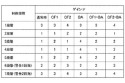
図10は、内部温度カウンタのゲインνの一例を示す図である。ここでは、ストロボマイコン310は、図10に示すゲインνに関するテーブルを有しているものとする。
FIG. 10 is a diagram showing an example of the gain ν of the internal temperature counter. Here, it is assumed that the
図10においては光学アクセサリ500が装着されていない場合の通常状態、光学アクセサリ500としてカラーフィルタCF1およびCF2、バウンスアダプタBAが装着可能なストロボ300に係るゲインνが示されている。なお、カラーフィルタCF1およびCF2とバウンスアダプタBAは同時に装着することができる。
FIG. 10 shows a normal state when the
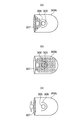
図11は、図1に示す発光部に光学アクセサリを装着する際の様子を説明するための図である。そして、図11(a)は光学アクセサリとしてカラーフィルタを示す図であり、図11(b)は光学アクセサリとしてバウンスアダプタを示す図である。また、図11(c)は発光部の下部にあるアクセサリ検知部を示す図であり、図11(d)は発光部にカラーフィルタおよびバウンスアダプタが装着された状態を示す図である。 FIG. 11 is a diagram for explaining a state when the optical accessory is attached to the light emitting portion shown in FIG. 11 (a) is a diagram showing a color filter as an optical accessory, and FIG. 11 (b) is a diagram showing a bounce adapter as an optical accessory. Further, FIG. 11C is a diagram showing an accessory detection unit below the light emitting unit, and FIG. 11D is a diagram showing a state in which a color filter and a bounce adapter are attached to the light emitting unit.
図11(a)において、カラーフィルタ510は突起部511および512を備えている。カラーフィルタ510を発光部300bに装着した際、突起部511および512のいずれかに形成された先端部によってアクセサリ検知部370が押圧される。これによって、カラーフィルタ510の発光部300bへの装着が検知される。上記の先端部は突起部511および512のいずれに形成されているかによって、調色された色を判別可能となっている。例えば、突起部511に先端部が形成されていた場合には、アクセサリ検知部370のスイッチ部373が押されることによって調色された色を判別している(図11(c)参照)。
In FIG. 11A, the
図11(b)において、バウンスアダプタ520についても同様に、突起部521および522を有している。そして、バウンスアダプタ510を発光部300bに装着した際、突起部521および522のいずれかに形成された先端部によってアクセサリ検知部370が押圧される。これによって、カラーフィルタ510の発光部300bへの装着が検知される。
In FIG. 11B, the
図示の例では、バウンスアダプタ520は1種類とし、突起部522がスイッチ部371を押すことによって、バウンスアダプタの検知が可能となっている(図11(c)参照)。そして、突起部521およびスイッチ部374は保持部として用いられる。カラーフィルタ510およびバウンスアダプタ520がスイッチ部371〜373に個々に対応付けられている。これによって、図11(d)に示すように、カラーフィルタ510およびバウンスアダプタ520を組み合わせて装着することができる。
In the illustrated example, there is only one type of
以下の説明では、調色が異なる二種類のカラーフィルタ510をそれぞれCF1およびCF2とし、バウンスアダプタ520をBAとして説明する。
In the following description, two types of
図10においては、通常時における発光間隔の短い制御段階の1段階と、光学パネル307が温度上昇している警告1段階(第1の警告段階)および警告2段階(第2の警告段階)においてゲインνを上げて、光学パネル307を保護している。一方、CF1装着の際には、光学パネル307が放熱しにくい状態となるので、通常時よりもゲインνを上げる。これによって、恰も大きな発光エネルギーNLであるとして光学パネル307を保護している。
In FIG. 10, there are one stage of a control stage in which the light emission interval is short in a normal state, and one stage of warning (first warning stage) and two stages of warning (second warning stage) in which the temperature of the
例えば、CF1装着の際には、3段階および5段階のゲインνを1から2に上げる。CF2又はBAの場合も同様に、各々の放熱特性に合わせてゲインνを設定することによって、見掛け上の温度上昇を表現することができる。また、CF1+BAにおいては、ゲインνについては組み合わせる光学アクセサリ500の各制御段階の大きい方のゲインνを用いる。さらには、CF2+BAのように個別に設定するようにしてもよい。
For example, when CF1 is attached, the gain ν in the 3rd and 5th stages is increased from 1 to 2. Similarly, in the case of CF2 or BA, an apparent temperature rise can be expressed by setting the gain ν according to each heat dissipation characteristic. Further, in CF1 + BA, for the gain ν, the larger gain ν of each control stage of the
このように、図9に示すステップS901において得た光学アクセサリ500に係る情報に基づいてゲインνを取得して、ストロボマイコン310は当該ゲインνを内蔵メモリに格納して、ステップS904に進む。
In this way, the gain ν is acquired based on the information related to the
ステップS903において、ストロボマイコン310は、式(19)の五式目を用いて内部温度カウンタCiを求める。そして、ストロボマイコン310は内蔵メモリにその演算結果を格納して、図4に示すステップS411の処理に進む。
In step S903, the
以上のように、恰も発熱が大きくなったように見せかければ、制御温度Tfを速く上昇させることができる。これによって、例えば、光学アクセサリ500の装着の有無をアクセサリ検知部370で検知し、その結果に基づいてゲインνを変更すれば、ストロボ300の発光可能回数および充電電流を調整することが可能となる。
As described above, the control temperature Tf can be raised quickly if the heat generation seems to have increased. Thereby, for example, if the
また、アクセサリ検知部370において光学アクセサリ500の種類などが判別可能であれば、個々の条件に合わせてゲインνを変更することも可能となる。その結果、放熱特性が低い光学アクセサリ500が装着された場合においても、ゲインνを変更して光学パネル307を損傷することなく運用することが可能となる。
Further, if the
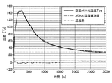
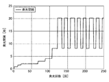
図12は、図1に示すストロボにおいて光学アクセサリの有無による光学パネルの最高温度の変化を示す図である。 FIG. 12 is a diagram showing a change in the maximum temperature of the optical panel depending on the presence or absence of an optical accessory in the strobe shown in FIG.
図12において、横軸は発光開始からの経過時間、縦軸は光学パネル307の表面温度を示す。実線で示す「光学アクセサリ500無し」は、放電管305を130回発光させた場合の光学パネル307の温度変化を示す。また、破線で示す「光学アクセサリ500有り」は放電管305を117回発光させた時の光学パネル307の温度変化を示す。なお、放熱の際に「光学アクセサリ500有り」の温度が下がり難いのは、光学パネル307を覆うように光学アクセサリ500が装着されているので、光学パネル307の熱が逃げ難い状態となっているためである。
In FIG. 12, the horizontal axis represents the elapsed time from the start of light emission, and the vertical axis represents the surface temperature of the
このように、光学アクセサリ500の有無によって連続発光回数が変更された結果、光学アクセサリ500が装着された場合に、光学パネル307の最高温度が通常時(光学アクセサリなし)と同等に抑えられていることが分かる。
As a result of changing the number of continuous light emission depending on the presence or absence of the
図10に関連して説明したように、式(19)の五式目のゲインνを制御段階毎に変更しているので、光学アクセサリ500の有無にかかわらず、急激な温度上昇又は警告段階における動作を調整することが可能となる。これによって、制御1段階において短い発光間隔による急激な温度上昇の防止又は警告段階において表示上のチャタリングを防止することができる。
As described in connection with FIG. 10, since the gain ν of the fifth equation of the equation (19) is changed for each control stage, the temperature rises sharply or the warning stage occurs regardless of the presence or absence of the
図13は、図1に示すストロボにおいて表示上のチャタリングを防止するための警告段階における動作の一例を示す図である。 FIG. 13 is a diagram showing an example of an operation in the warning stage for preventing chattering on the display in the strobe shown in FIG.
図13において、発光間隔が約8秒である場合が警告1段階、発光間隔が約20秒である場合が警告2段階である。通常、光学パネル307の温度を制御すると閾値付近で所謂表示上のチャタリングが発生する。一方、図13に示すように、光学パネル307の温度が上昇して警告2段階となったとする。この際には、判定処理用サンプリングタイムおよびゲインνの設定によって、光学パネル307の温度がある程度下がった段階で警告2段階から警告1段階に移行する動作が可能となる。
In FIG. 13, when the light emission interval is about 8 seconds, there is one warning stage, and when the light emission interval is about 20 seconds, there are two warning stages. Normally, when the temperature of the
さらに、連続発光を行って光学パネル307の温度が上昇した場合には、再度警告2段階に移行するという動作が可能となって、表示上又は制御上におけるチャタリングを防止することができる。
Further, when the temperature of the
図14は、図4に示すズーム位置変更処理を説明するためのフローチャートである。 FIG. 14 is a flowchart for explaining the zoom position change process shown in FIG.
ズーム位置変更処理を開始すると、ストロボマイコン310は、ズーム位置変更前のズーム位置における制御段階に係る制御温度Tfの判定閾値を内蔵メモリ(例えば、EEPROM)から読み込む(ステップS1401)。判定閾値の上限値を用いるか又は下限値を用いるかについてEEPROMに格納されている閾値によって異なるが、下限値を用いる場合には制御段階1段階目の閾値が0となっている場合である。この場合には、当該制御段階の一つ上の段階の閾値を用いるようにしてもよい。
When the zoom position change process is started, the
続いて、ストロボマイコン310は、ズーム位置変更後のズーム位置における制御段階に係る制御温度Tfの判定閾値を内蔵メモリから読み込む(ステップS1402)。判定閾値の上限値を用いるか又は下限値を用いるかについてはステップS1401の場合と同一にする必要がある。
Subsequently, the
次に、ストロボマイコン310は、図4に示すステップS409の処理で得られたパネル温度カウンタCpについて変更処理を行う(ステップS1403)。この処理は、各ズーム位置における制御段階のレンジが異なるために行われる。変更処理後のパネル温度カウンタは変換前閾値をFPZ、変換後閾値をFAZとして、式(19)の四式目を用いて、次の式(20)によって求めることができる。
Next, the
![]()
![]()
変換処理後、ストロボマイコン310は内蔵メモリに変換処理の結果を格納する。そして、ストロボマイコン310は、ステップS1403の処理と同様にして、ステップS410の処理で得られた内部温度カウンタCiについて変更処理を行う(ステップS1404)。変更処理後の内部温度カウンタは変換前閾値をFPZ、変換後閾値をFAZとして、式(19)の五式目を用いて、次の式(21)によって求めることができる。
After the conversion process, the
![]()
![]()
変換処理後、ストロボマイコン310は内蔵メモリに変換処理の結果を格納する。そして、ストロボマイコン310は、変更後のズーム位置に対応付けて変換処理の結果を内蔵メモリに格納して(ステップS1405)、次回のサンプリングで使用できるようにする。その後、ストロボマイコン310はズーム位置変更処理を終了する。この際、ストロボマイコン310はズーム位置が変更されたことを示すビットを付加する。当該ビットが付加された場合には、ストロボマイコン310は図4に示すステップS408の判定処理を行わない。つまり、連続発光制御においてフィードバックが行われている結果、ズーム位置の変更直後においては以前のズーム位置で演算されたパネル温度カウンタCpおよび内部温度カウンタCiを用いて制御温度Tfが演算されることになる。この段階で制御段階判定が行われると、一時的に制御段階が正規の値からずれる可能性があるため、ストロボマイコン310はステップS408の判定処理を行わない。
After the conversion process, the
このようにして、本発明の第1の実施形態では、光学アクセサリの有無に拘わらず、異常な温度上昇を防いで発光を適切に制御することによって、発光による発熱から保護対象部位である光学パネルなどを保護することができる。 In this way, in the first embodiment of the present invention, the optical panel which is a portion to be protected from heat generation due to light emission by preventing an abnormal temperature rise and appropriately controlling light emission regardless of the presence or absence of an optical accessory. Etc. can be protected.
[第2の実施形態]
次に、本発明の第2の実施形態によるストロボを備えるカメラの一例について説明する。なお、第2の実施形態によるカメラの構成は図1および図2に示すカメラと同であるので、説明を省略する。
[Second Embodiment]
Next, an example of a camera including a strobe according to a second embodiment of the present invention will be described. Since the configuration of the camera according to the second embodiment is the same as that of the cameras shown in FIGS. 1 and 2, the description thereof will be omitted.
上述の第1の実施形態では、発光エネルギーNLをズーム位置に拘わらず算出して、ズーム位置毎に閾値を変更することによって発光を制御するようにした。一方、第2の実施形態では、発光エネルギーNLをズーム位置による光学パネル307に対する影響を考慮して算出して、全てのズーム域において共通の閾値を用いて発光を制御する。
In the first embodiment described above, the light emission energy NL is calculated regardless of the zoom position, and the light emission is controlled by changing the threshold value for each zoom position. On the other hand, in the second embodiment, the light emission energy NL is calculated in consideration of the influence of the zoom position on the
図15は、本発明の第2の実施形態によるストロボで行われる連続発光制御を説明するためのフローチャートである。なお、図15において、図4に示すフローチャートと同一のステップについては同一の参照符号を付して説明を省略する。また、第2の実施形態において、他の処理は第1の実施形態で説明した処理と同様である。 FIG. 15 is a flowchart for explaining continuous flash control performed by the strobe according to the second embodiment of the present invention. In FIG. 15, the same steps as those in the flowchart shown in FIG. 4 are designated by the same reference numerals and the description thereof will be omitted. Further, in the second embodiment, the other processes are the same as the processes described in the first embodiment.
光学アクセサリの確認を行った後、ストロボマイコン310は、サンプリング中に発光した発光エネルギーNLを取得する(ステップS1504)。ストロボマイコン310は、発光エネルギーNLを、メインコンデンサ302dの電圧、フォトダイオード314から得られる発光量の積分値、又はカメラ本体100からの発光指令に基づいて算出する。
After confirming the optical accessories, the
まず、メインコンデンサ302dの電圧に基づいて発光エネルギーNLを算出する場合について説明する。
First, a case where the emission energy NL is calculated based on the voltage of the
メインコンデンサ302dの発光前電圧をbVCMとし、発光後電圧をaVCMとすると、エネルギーECZは二乗差によって次の式(22)で求められる。
Assuming that the pre-emission voltage of the
ストロボマイコン310は、発光前電圧bVCMおよび発光後電圧aVCMをそれぞれメインコンデンサ302dに関するA/D変換値から得る。そして、ストロボマイコン310は演算可能なレンジによってゲインOsで出力レンジを調整する。
The
ズーム位置係数Zoおよびズーム位置補正値Zgは、ズーム位置によって異なる光学パネル307に対する影響度を示す係数である。これらの係数はストロボ光が光学パネル307を通過する際のズーム位置毎の有効面積、ズーム位置毎の光学パネル307と放電管305との距離、および反射傘306による集光度合などに基づいて設定される。
The zoom position coefficient Zo and the zoom position correction value Zg are coefficients that indicate the degree of influence on the
発光エネルギーNLは、連続発光制御で用いる出力レンジに合わせて次の式(23)によってエネルギーECZを変換して得る。 The emission energy NL is obtained by converting the energy ECZ according to the following equation (23) according to the output range used in the continuous emission control.
![]()
![]()
なお、係数αおよびβはストロボ300の構成などによって異なり、予め得られた測定データに基づいて調整する。
The coefficients α and β differ depending on the configuration of the
次に、フォトダイオード314から得られる発光量の積分値に基づいて発光エネルギーNLを算出する場合について説明する。
Next, a case where the emission energy NL is calculated based on the integrated value of the emission amount obtained from the
ストロボマイコン310は、発光後に得られる発光量の積分値ALに基づいて次の式(24)によってエネルギーECZを求める。
The
![]()
![]()
ストロボマイコン310は、連続発光制御で用いる出力レンジに合わせてゲインOsを調整して近似的にエネルギーとして扱う。その後、ストロボマイコン310は、メインコンデンサ302dの電圧から求める場合と同様にして、式(23)によって出力レンジを調整して発光エネルギーNLを得る。なお、EEPROMなどに発光量の積分値ALと発光エネルギーNLと関係を示す変換テーブルを記憶させて、当該変換テーブルを用いて発光エネルギーNLを求めるようにしてもよい。
The
カメラ本体100から送られる発光指令に基づいて発光エネルギーNLを算出する場合も同様にして変換が行われる。そして、連続発光制御で用いる出力レンジに合わせてゲインOsを調整して近似的にエネルギーECZとして扱う。
When the light emission energy NL is calculated based on the light emission command sent from the
カメラ本体100からの発光指令をEとすると、エネルギーECZは次の式(25)で表される。
Assuming that the light emission command from the
![]()
![]()
ストロボマイコン310はメインコンデンサ302dの電圧から求める場合と同様にして、式(23)によって出力レンジを調整して発光エネルギーNLを得る。なお、EEPROMなどに発光指令Eと発光エネルギーNLと関係を示す変換テーブルを記憶させて、当該変換テーブルを用いて発光エネルギーELを求めるようにしてもよい。
The
発光エネルギーNLを求めた後、ストロボマイコン310は内蔵メモリに発光エネルギーNL格納して、ステップS405に進む。
After obtaining the light emission energy NL, the
ステップS411の処理の後、ストロボマイコン310は、上記の発光エネルギーNLおよび上記の演算結果を内蔵メモリに格納して(ステップS1512)、次回のサンプリングで使用できるようにする。その後、ストロボマイコン310は、ステップS415の処理に進む。
After the process of step S411, the
このように、本発明の第2の実施形態では、ズーム位置による光学パネル307に対する影響が発光エネルギーNLに含まれる。この結果、全てのズーム位置で共通の制御段階判定閾値を用いることができる。よって、第2の実施形態では、ズーム位置変更処理を行う必要がない。
As described above, in the second embodiment of the present invention, the influence of the zoom position on the
一方、第2の実施形態においても、光学アクセサリ500が装着された際の制御は第1の実施形態と同様にして制御が行われる。つまり、第2の実施形態では、式(19)の五式目のゲインνを変更することによって発光を制御する。または、光学アクセサリ500の装着の際には通常時の制御段階判定閾値とは異なる制御段階判定閾値を設定して制御が行われる。
On the other hand, also in the second embodiment, the control when the
なお、第1の実施形態においては、式(19)の五式目のゲインνを変更して発光を制御する手法について説明した。よって、制御段階判定閾値を変更する制御については、図5に示すステップS501において、通常時の制御段階判定閾値と異なる制御段階判定閾値が設定される。この場合には、式(19)の五式目のゲインνを変更することによる発光制御を行わないので、図9に示すステップS903の処理は省略される。 In the first embodiment, a method of controlling the light emission by changing the gain ν of the fifth equation of the equation (19) has been described. Therefore, for the control for changing the control stage determination threshold, a control stage determination threshold different from the normal control stage determination threshold is set in step S501 shown in FIG. In this case, since the light emission control is not performed by changing the gain ν of the fifth equation of the equation (19), the process of step S903 shown in FIG. 9 is omitted.
[第3の実施形態]
次に、本発明の第3の実施形態によるストロボ390を備えるカメラの一例について説明する。
[Third Embodiment]
Next, an example of a camera including a
図16は、本発明の第3の実施形態によるストロボ390を備えるカメラの一例についてその構成を示す図である。なお、図16において、図1に示すカメラと同一の構成要素については同一の参照番号を付して説明を省略する。
FIG. 16 is a diagram showing a configuration of an example of a camera provided with a
図示のカメラにおいては、ストロボ390が内部温度測定部360、外気温測定部361、および照度測定部362を備えている点で、図1に示すカメラと異なる。第3の実施形態においては、内部温度測定部360、外気温測定部361、および照度測定部362の出力結果に基づいて連続発光制御が行われる。
The illustrated camera differs from the camera shown in FIG. 1 in that the
内部温度測定部360は、発光部300bの内部温度を測定する温度センサーを有している。外気温測定部361は、ストロボ390において最も熱の影響を受けにくい位置で外気温を測定する温度センサーを有している。また、照度測定部362は、放電管305が発光した際の照度を測定する照度センサーを有している。
The internal temperature measuring unit 360 has a temperature sensor that measures the internal temperature of the
ここで、ストロボ390の連続発光制御で用いられる演算式について説明する。
Here, the arithmetic expression used in the continuous flash control of the
図4に示すステップS404において、ストロボマイコン310は発光エネルギーNLを照度測定部362の出力結果に基づいて算出する。照度測定部362の出力結果を照度Ilとすると、エネルギーECは次の式(26)で得られる。
In step S404 shown in FIG. 4, the
![]()
![]()
なお、係数ωおよびψはストロボ390の構成などよって異なり、予め測定された測定データに基づいて調整される。
The coefficients ω and ψ differ depending on the configuration of the
式(26)を式(2)に代入することによって、発光エネルギーNLが求められる。 By substituting the equation (26) into the equation (2), the emission energy NL can be obtained.
図4に示すステップS410において、ストロボマイコン310は内部温度カウンタCiを内部温度測定部360の出力結果に基づいて算出する。内部温度測定部360の出力結果を内部Tiとすると、内部温度カウンタCiは次の式(27)で得られる。
In step S410 shown in FIG. 4, the
![]()
![]()
係数σおよびτはストロボ390の構成などよって異なり、予め測定された測定データに基づいて調整される。
The coefficients σ and τ differ depending on the configuration of the
さらに、式(13)と外気温測定部361の出力結果である環境温度Tを用いて、想定パネル温度Tpsを求めることができる。これによって、制御温度Tfの演算結果を補正することで、環境温度Tに合わせて連続発光制御を行うことができる。
Further, the assumed panel temperature Tps can be obtained by using the equation (13) and the environmental temperature T which is the output result of the outside air
次に、制御段階判定処理ついて説明する。図5に示すステップS501において、ストロボマイコン310は、図4に示すステップS407で求めた制御温度Tfが所定の閾値を超えているか否かを判定する。光学アクセサリ500が装着された際には、通常時の制御段階判定閾値とは異なる制御段階判定閾値が設定される。制御段階に変更が生じる場合には、変更後の制御段階に判定結果を更新して、ストロボマイコン310は内蔵メモリにその判定結果を格納する。その後、ストロボマイコンはステップS502の処理に進む。
Next, the control stage determination process will be described. In step S501 shown in FIG. 5, the
以降、第1の実施形態と同様の処理が行われて、連続発光制御が終了する。但し、第3の実施形態では、式(19)の五式目のゲインνを変更することによって発光を制御する手法を用いないので、図9に示すステップS903の処理は省略される。 After that, the same processing as in the first embodiment is performed, and the continuous light emission control is completed. However, in the third embodiment, since the method of controlling the light emission by changing the gain ν of the fifth equation of the equation (19) is not used, the process of step S903 shown in FIG. 9 is omitted.
このように、本発明の第3の実施形態では、ストロボ390に備えられた内部温度測定部360、外気温測定部361、および照度測定部362の出力結果に基づいて連続発光制御を行う。
As described above, in the third embodiment of the present invention, continuous light emission control is performed based on the output results of the internal temperature measuring unit 360, the outside air
[第4の実施形態]
次に、本発明の第4の実施形態によるストロボを備えるカメラの一例について説明する。なお、第4の実施形態によるカメラの構成は図1および図2に示すカメラと同じであるので、説明を省略する。
[Fourth Embodiment]
Next, an example of a camera including a strobe according to a fourth embodiment of the present invention will be described. Since the configuration of the camera according to the fourth embodiment is the same as that of the cameras shown in FIGS. 1 and 2, the description thereof will be omitted.
上述の第1の実施形態では、光学パネル307の温度上昇を想定するとともに光学アクセサリ500が装着された際の温度を想定して、発光を制御するようにした。一方、第4の実施形態では、連続発光可能回数などを光学アクセサリ500の装着の有無およびその種類に応じて直接設定して、ストロボマイコン310の演算処理能力が低い場合においても光学パネル307の損傷などを防ぐようにする。
In the first embodiment described above, the light emission is controlled by assuming a temperature rise of the
図17は、本発明の第4の実施形態によるストロボで行われる連続発光制御を説明するためのフローチャートである。なお、図17において、図4に示すフローチャートと同一のステップについては同一の参照符号を付して説明を省略する。また、第4の実施形態において、他の処理は第1の実施形態で説明した処理と同様である。 FIG. 17 is a flowchart for explaining continuous flash control performed by the strobe according to the fourth embodiment of the present invention. In FIG. 17, the same steps as those in the flowchart shown in FIG. 4 are designated by the same reference numerals, and the description thereof will be omitted. Further, in the fourth embodiment, the other processes are the same as the processes described in the first embodiment.
光学アクセサリの確認を行った後、ストロボマイコン310は発光エネルギーNLを取得する(ステップS1703)。ステップS1703の処理では、第1又は第2の実施形態で説明したようにして、発光エネルギーNLを得る。
After confirming the optical accessories, the
ここでは、説明の簡単化のため、ストロボマイコン310は第2の実施形態で説明したようにして発光エネルギーNLを得る。但し、必ずしも式(5)で示すサンプリングタイムの合計を取得する必要はない。図4に示すステップS405〜S411の処理を行わない場合には、サンプリング毎に取得することなく発光タイミング毎に取得するようにしてもよい。
Here, for simplification of the description, the
以下の説明では発光タイミング毎に取得した場合について説明する。発光エネルギーNLを取得した後、ストロボマイコン310は当該発光エネルギーNLを内蔵メモリに格納する。ステップS1704へ移行する。
In the following description, the case where the data is acquired for each light emission timing will be described. After acquiring the light emission energy NL, the
続いて、ストロボマイコン310は連続発光処理演算を行う(ステップS1704)。連続発光処理演算においては、ストロボマイコン310はステップS403で得た光学アクセサリ情報に基づいて、発光回数を変更するためのカウントを行う。例えば、ストロボマイコン310は発光エネルギーNLを発光毎に加算するカウントを行う。さらに、ストロボマイコン310は所定の時間毎に所定の量を発光エネルギーNLから減算する。
Subsequently, the
連続発光処理演算が終了すると、ストロボマイコン310は内蔵メモリにその演算結果を格納する。次に、ストロボマイコン310は、ステップS1704で得られた演算結果が所定の閾値を超えているか否か、つまり、警告段階であるか否かを判定する(ステップS1705)。
When the continuous flash processing calculation is completed, the
発光回数を設定する際の判定に用いる閾値Sは、フル発光相当の発光エネルギーをFNL、発光回数をNとすると、次の式(28)で得られる。 The threshold value S used for the determination when setting the number of light emission is obtained by the following equation (28), where FNL is the light emission energy equivalent to full light emission and N is the number of light emission.
![]()
![]()
式(28)を用いて、光学アクセサリ情報に基づいて発光回数Nを変更すれば、直接発光回数を設定することができる。発光回数Nは、ストロボ300および光学アクセサリ500の構成などに応じて実験的に求めればよい。なお、閾値Sは発光エネルギーの合計と同義であるので、総発光量として設定するようにしてもよい。そして、ストロボマイコン310は、図4のステップS408で説明した処理を行って、前述のステップS414の処理に進む。
If the number of light emission N is changed based on the optical accessory information using the formula (28), the number of light emission can be directly set. The number of flashes N may be experimentally determined according to the configuration of the
このように、本発明の第4の実施形態では、連続発光回数又は総発光量を設定して発光を制御できるので、光学パネル307の温度上昇を正確に演算することなく容易に光学アクセサリ500の装着の際の発光制御を変更することができる。
As described above, in the fourth embodiment of the present invention, since the number of continuous light emission or the total light emission amount can be set to control the light emission, the
なお、上述の実施の形態では、ストロボマイコンはマイコン内蔵ワンチップIC回路として説明したが、専用の演算部などの回路を設けるようにしてもよい。さらに、上述のフローチャートは一例であって、必要に応じて上記のフローチャートと異なる順序で処理を実行するようにしてもよい。 In the above-described embodiment, the strobe microcomputer has been described as a one-chip IC circuit with a built-in microcomputer, but a circuit such as a dedicated arithmetic unit may be provided. Further, the above-mentioned flowchart is an example, and the processes may be executed in a different order from the above-mentioned flowchart as needed.
以上、本発明について実施の形態に基づいて説明したが、本発明は、これらの実施の形態に限定されるものではなく、この発明の要旨を逸脱しない範囲の様々な形態も本発明に含まれる。 Although the present invention has been described above based on the embodiments, the present invention is not limited to these embodiments, and various embodiments within the scope of the gist of the present invention are also included in the present invention. ..
例えば、上記の実施の形態の機能を制御方法として、この制御方法を照明装置に実行させるようにすればよい。また、上述の実施の形態の機能を有するプログラムを制御プログラムとして、当該制御プログラムを照明装置が備えるコンピュータに実行させるようにしてもよい。なお、制御プログラムは、例えば、コンピュータに読み取り可能な記録媒体に記録される。 For example, the function of the above-described embodiment may be used as a control method, and the lighting device may be made to execute this control method. Further, a program having the function of the above-described embodiment may be used as a control program, and the control program may be executed by a computer provided in the lighting device. The control program is recorded on, for example, a computer-readable recording medium.
[その他の実施形態]
上述の実施形態の1以上の機能を実現するプログラムをネットワーク又は記憶媒体を介してシステム又は装置に供給する。そして、そのシステム又は装置のコンピュータにおける1つ以上のプロセッサーがプログラムを読出し実行する処理でも本発明は実現可能である。また、1以上の機能を実現する回路(例えば、ASIC)によっても実現可能である。
[Other Embodiments]
A program that realizes one or more functions of the above-described embodiment is supplied to the system or device via a network or a storage medium. The present invention can also be realized by a process in which one or more processors in the computer of the system or apparatus reads and executes a program. It can also be realized by a circuit (for example, ASIC) that realizes one or more functions.
100 カメラ本体
101 カメラマイコン
200 撮影レンズ(レンズユニット)
201 レンズマイコン
300 ストロボ
300a 本体部
300b 発光部
310 ストロボマイコン
370 アクセサリ検知部
500 光学アクセサリ
100
201
Claims (5)
前記発光手段に調色又は配光角調整のための光学アクセサリが装着されたか否かを検知する検知手段と、
前記検知手段による検知結果に基づいて、前記光学アクセサリが装着されている場合は前記光学アクセサリが装着されていない場合よりも、前記発光手段の最短発光間隔が長くなるように制御する制御手段と、を有し、
前記発光手段は、前記発光手段の発光によって温度上昇する対象部位との相対位置を変更可能に保持されていて、
前記制御手段は、前記発光手段と前記対象部位との相対位置に基づいて前記最短発光間隔を制御することを特徴とする照明装置。 Light emitting means and
A detection means for detecting whether or not an optical accessory for toning or adjusting the light distribution angle is attached to the light emitting means, and
Based on the detection result by the detection means, the control means for controlling so that the shortest light emission interval of the light emitting means is longer when the optical accessory is attached than when the optical accessory is not attached. Have,
The light emitting means is held so that the relative position with respect to the target portion whose temperature rises due to the light emission of the light emitting means can be changed.
The control means is a lighting device characterized in that the shortest light emission interval is controlled based on a relative position between the light emitting means and the target portion.
請求項1または2に記載の照明装置と、
を有することを特徴とする撮像装置。 An imaging means that captures an image of a subject via an imaging optical system and obtains an image.
The lighting device according to claim 1 or 2,
An imaging device characterized by having.
前記検知ステップによる検知結果に基づいて、前記光学アクセサリが装着されている場合は前記光学アクセサリが装着されていない場合よりも、前記発光手段の最短発光間隔が長くなるように制御する制御ステップと、を有し、
前記制御ステップは、前記発光手段と前記発光手段の発光によって温度上昇する対象部位との変更可能な相対位置に基づいて前記最短発光間隔を制御することを特徴とする照明装置の制御方法。 A detection step that detects whether or not an optical accessory for toning or adjusting the light distribution angle is attached to the light emitting means,
Based on the detection result by the detection step, a control step for controlling so that the shortest light emission interval of the light emitting means is longer when the optical accessory is attached than when the optical accessory is not attached. Have,
The control step is a control method for a lighting device, characterized in that the shortest light emission interval is controlled based on a changeable relative position between the light emitting means and a target portion whose temperature rises due to the light emission of the light emitting means.
前記照明装置が備えるコンピュータに、
前記発光手段に調色又は配光角調整のための光学アクセサリが装着されたか否かを検知する検知ステップと、
前記検知ステップによる検知結果に基づいて、前記光学アクセサリが装着されている場合は前記光学アクセサリが装着されていない場合よりも、前記発光手段の最短発光間隔が長くなるように制御する制御ステップと、を実行させ、
前記制御ステップは、前記発光手段と前記発光手段の発光によって温度上昇する対象部位との変更可能な相対位置に基づいて前記最短発光間隔を制御することを特徴とする制御プログラム。 A control program used in a lighting device having a light emitting means.
To the computer provided in the lighting device
A detection step for detecting whether or not an optical accessory for toning or adjusting the light distribution angle is attached to the light emitting means, and
Based on the detection result by the detection step, a control step for controlling so that the shortest light emission interval of the light emitting means is longer when the optical accessory is attached than when the optical accessory is not attached. To execute,
The control step is a control program characterized in that the shortest light emission interval is controlled based on a changeable relative position between the light emitting means and a target portion whose temperature rises due to the light emission of the light emitting means.
Priority Applications (3)
| Application Number | Priority Date | Filing Date | Title |
|---|---|---|---|
| JP2016041116A JP6866068B2 (en) | 2016-03-03 | 2016-03-03 | Lighting equipment, its control method, and control program, and imaging equipment |
| US15/446,854 US10158794B2 (en) | 2016-03-03 | 2017-03-01 | Lighting device that controls light emission while suppressing temperature rise, image pickup apparatus, and method of controlling lighting device |
| CN201710124325.4A CN107155069B (en) | 2016-03-03 | 2017-03-03 | Illumination device, control method thereof, and image pickup apparatus |
Applications Claiming Priority (1)
| Application Number | Priority Date | Filing Date | Title |
|---|---|---|---|
| JP2016041116A JP6866068B2 (en) | 2016-03-03 | 2016-03-03 | Lighting equipment, its control method, and control program, and imaging equipment |
Publications (3)
| Publication Number | Publication Date |
|---|---|
| JP2017156625A JP2017156625A (en) | 2017-09-07 |
| JP2017156625A5 JP2017156625A5 (en) | 2019-04-11 |
| JP6866068B2 true JP6866068B2 (en) | 2021-04-28 |
Family
ID=59724447
Family Applications (1)
| Application Number | Title | Priority Date | Filing Date |
|---|---|---|---|
| JP2016041116A Active JP6866068B2 (en) | 2016-03-03 | 2016-03-03 | Lighting equipment, its control method, and control program, and imaging equipment |
Country Status (3)
| Country | Link |
|---|---|
| US (1) | US10158794B2 (en) |
| JP (1) | JP6866068B2 (en) |
| CN (1) | CN107155069B (en) |
Families Citing this family (5)
| Publication number | Priority date | Publication date | Assignee | Title |
|---|---|---|---|---|
| JP2019132914A (en) * | 2018-01-29 | 2019-08-08 | キヤノン株式会社 | Illumination device and camera system including teh same |
| JP7258589B2 (en) * | 2019-02-18 | 2023-04-17 | キヤノン株式会社 | Lighting device and its control method, imaging device |
| JP7204530B2 (en) * | 2019-02-28 | 2023-01-16 | キヤノン株式会社 | Lighting device and its control method |
| CN112885939B (en) * | 2019-11-13 | 2022-12-20 | 北京小米移动软件有限公司 | Packaging structure, electronic equipment and transmitting device thereof |
| JP6968473B1 (en) * | 2021-05-26 | 2021-11-17 | 株式会社Photo electron Soul | Electron gun, electron beam application device, and electron beam emission method |
Family Cites Families (15)
| Publication number | Priority date | Publication date | Assignee | Title |
|---|---|---|---|---|
| US5485201A (en) * | 1992-08-28 | 1996-01-16 | Asahi Kogaku Kogyo Kabushiki Kaisha | Fill-in light emitting apparatus and still video camera |
| GB2296782B (en) * | 1994-12-28 | 1998-06-17 | Asahi Optical Co Ltd | Flashlight control apparatus |
| JP2003021858A (en) * | 2001-07-09 | 2003-01-24 | Fuji Photo Film Co Ltd | Image pickup device |
| JP5116309B2 (en) | 2007-01-29 | 2013-01-09 | キヤノン株式会社 | Strobe device and control method thereof |
| JP2009020298A (en) * | 2007-07-11 | 2009-01-29 | Nikon Corp | Illuminating device, attachment to illuminating device, camera, illuminating system and camera system |
| US20100124041A1 (en) * | 2008-11-17 | 2010-05-20 | Vitaly Druchinin | Systems and methods for controlling flash color temperature |
| KR20120129468A (en) * | 2011-05-20 | 2012-11-28 | 삼성전자주식회사 | Apparatus and method for controlling flash in portable terminal |
| US9049361B2 (en) * | 2012-01-06 | 2015-06-02 | Canon Kabushiki Kaisha | Illumination device capable of having optical accessory attached forward of light emission section thereof, image pickup system, film holder, light emission control device, and light emission control method |
| JP2013142883A (en) * | 2012-01-13 | 2013-07-22 | Canon Inc | Camera system including flash device |
| KR101932723B1 (en) * | 2012-12-28 | 2018-12-27 | 삼성전자주식회사 | Photographing apparatus |
| US9504103B2 (en) * | 2013-10-21 | 2016-11-22 | Osram Sylvania Inc. | Driving a multi-color luminaire |
| JP6391274B2 (en) * | 2014-04-04 | 2018-09-19 | キヤノン株式会社 | Lighting device |
| US10045427B2 (en) * | 2014-09-29 | 2018-08-07 | Philips Lighting Holding B.V. | System and method of autonomous restore point creation and restoration for luminaire controllers |
| US9596393B2 (en) * | 2015-01-27 | 2017-03-14 | Moment Inc | Smart case for mobile photography |
| US9716818B2 (en) * | 2015-05-07 | 2017-07-25 | Canon Kabushiki Kaisha | Illumination apparatus having first case and second case rotatable relative to first case, and imaging apparatus having detachable illumination apparatus |
-
2016
- 2016-03-03 JP JP2016041116A patent/JP6866068B2/en active Active
-
2017
- 2017-03-01 US US15/446,854 patent/US10158794B2/en active Active
- 2017-03-03 CN CN201710124325.4A patent/CN107155069B/en active Active
Also Published As
| Publication number | Publication date |
|---|---|
| JP2017156625A (en) | 2017-09-07 |
| CN107155069B (en) | 2021-07-20 |
| US10158794B2 (en) | 2018-12-18 |
| US20170257541A1 (en) | 2017-09-07 |
| CN107155069A (en) | 2017-09-12 |
Similar Documents
| Publication | Publication Date | Title |
|---|---|---|
| JP5268438B2 (en) | Strobe device, imaging device, and control method thereof | |
| JP6866068B2 (en) | Lighting equipment, its control method, and control program, and imaging equipment | |
| JP5769436B2 (en) | Imaging device, communication device, and camera system | |
| JP6573367B2 (en) | Imaging device, control method thereof, and control program | |
| JP6758861B2 (en) | Lighting equipment, its control method, control program, and imaging device | |
| JP2004126493A (en) | Flash control device and flash control system | |
| JP2015219325A (en) | Stroboscope control system and stroboscope control method | |
| JP2015004908A (en) | Luminaire and control method | |
| JP6971710B2 (en) | Lighting equipment, its control method, control program, and lighting system, as well as imaging equipment. | |
| JP6016377B2 (en) | Illumination device and imaging system | |
| JP2013171075A (en) | Illuminating device | |
| JP7134737B2 (en) | IMAGING SYSTEM, IMAGING DEVICE, LIGHTING DEVICE, AND CONTROL METHOD | |
| JP5183188B2 (en) | Imaging device and strobe device | |
| JP6584128B2 (en) | LIGHTING DEVICE, IMAGING DEVICE, IMAGING SYSTEM, AND CONTROL METHOD THEREOF | |
| JP2015191000A (en) | Imaging device, flash device and flash photographing system | |
| JP2020134653A (en) | Lighting system, control method for the same and imaging device | |
| JP6873779B2 (en) | Imaging device, its control method, and control program | |
| CN111323992B (en) | Photographing system, illumination apparatus, and control method for setting light emission amount of flash | |
| JP2021015199A (en) | Camera stroboscope system | |
| JP2005115160A (en) | Electronic flash device, control method for electronic flash device, camera and camera system | |
| JP2009122523A (en) | Flash light device | |
| JP2018081121A (en) | Imaging system and control method thereof | |
| JP6489925B2 (en) | LIGHTING DEVICE, IMAGING DEVICE, IMAGING SYSTEM, AND CONTROL METHOD THEREOF | |
| JP2019086685A (en) | Illumination device, control method therefor, control program, and imaging apparatus | |
| JP2021152575A (en) | Light emission control device and light emission control method |
Legal Events
| Date | Code | Title | Description |
|---|---|---|---|
| A521 | Request for written amendment filed |
Free format text: JAPANESE INTERMEDIATE CODE: A523 Effective date: 20190304 |
|
| A621 | Written request for application examination |
Free format text: JAPANESE INTERMEDIATE CODE: A621 Effective date: 20190304 |
|
| A977 | Report on retrieval |
Free format text: JAPANESE INTERMEDIATE CODE: A971007 Effective date: 20200128 |
|
| A131 | Notification of reasons for refusal |
Free format text: JAPANESE INTERMEDIATE CODE: A131 Effective date: 20200218 |
|
| A601 | Written request for extension of time |
Free format text: JAPANESE INTERMEDIATE CODE: A601 Effective date: 20200403 |
|
| A521 | Request for written amendment filed |
Free format text: JAPANESE INTERMEDIATE CODE: A523 Effective date: 20200608 |
|
| A131 | Notification of reasons for refusal |
Free format text: JAPANESE INTERMEDIATE CODE: A131 Effective date: 20201110 |
|
| A521 | Request for written amendment filed |
Free format text: JAPANESE INTERMEDIATE CODE: A523 Effective date: 20210104 |
|
| TRDD | Decision of grant or rejection written | ||
| A01 | Written decision to grant a patent or to grant a registration (utility model) |
Free format text: JAPANESE INTERMEDIATE CODE: A01 Effective date: 20210309 |
|
| A61 | First payment of annual fees (during grant procedure) |
Free format text: JAPANESE INTERMEDIATE CODE: A61 Effective date: 20210407 |
|
| R151 | Written notification of patent or utility model registration |
Ref document number: 6866068 Country of ref document: JP Free format text: JAPANESE INTERMEDIATE CODE: R151 |