JP7204530B2 - Lighting device and its control method - Google Patents

Lighting device and its control method Download PDF

Info

Publication number
JP7204530B2
JP7204530B2 JP2019036138A JP2019036138A JP7204530B2 JP 7204530 B2 JP7204530 B2 JP 7204530B2 JP 2019036138 A JP2019036138 A JP 2019036138A JP 2019036138 A JP2019036138 A JP 2019036138A JP 7204530 B2 JP7204530 B2 JP 7204530B2
Authority
JP
Japan
Prior art keywords
temperature
light emission
light emitting
light
result
Prior art date
Legal status (The legal status is an assumption and is not a legal conclusion. Google has not performed a legal analysis and makes no representation as to the accuracy of the status listed.)
Active
Application number
JP2019036138A
Other languages
Japanese (ja)
Other versions
JP2020140875A (en
Inventor
慶一郎 齊藤
Current Assignee (The listed assignees may be inaccurate. Google has not performed a legal analysis and makes no representation or warranty as to the accuracy of the list.)
Canon Inc
Original Assignee
Canon Inc
Priority date (The priority date is an assumption and is not a legal conclusion. Google has not performed a legal analysis and makes no representation as to the accuracy of the date listed.)
Filing date
Publication date
Application filed by Canon Inc filed Critical Canon Inc
Priority to JP2019036138A priority Critical patent/JP7204530B2/en
Priority to US16/798,679 priority patent/US11162673B2/en
Priority to CN202010119708.4A priority patent/CN111629493B/en
Publication of JP2020140875A publication Critical patent/JP2020140875A/en
Application granted granted Critical
Publication of JP7204530B2 publication Critical patent/JP7204530B2/en
Active legal-status Critical Current
Anticipated expiration legal-status Critical

Links

Images

Classifications

    • GPHYSICS
    • G03PHOTOGRAPHY; CINEMATOGRAPHY; ANALOGOUS TECHNIQUES USING WAVES OTHER THAN OPTICAL WAVES; ELECTROGRAPHY; HOLOGRAPHY
    • G03BAPPARATUS OR ARRANGEMENTS FOR TAKING PHOTOGRAPHS OR FOR PROJECTING OR VIEWING THEM; APPARATUS OR ARRANGEMENTS EMPLOYING ANALOGOUS TECHNIQUES USING WAVES OTHER THAN OPTICAL WAVES; ACCESSORIES THEREFOR
    • G03B15/00Special procedures for taking photographs; Apparatus therefor
    • G03B15/02Illuminating scene
    • G03B15/03Combinations of cameras with lighting apparatus; Flash units
    • G03B15/05Combinations of cameras with electronic flash apparatus; Electronic flash units
    • FMECHANICAL ENGINEERING; LIGHTING; HEATING; WEAPONS; BLASTING
    • F21LIGHTING
    • F21VFUNCTIONAL FEATURES OR DETAILS OF LIGHTING DEVICES OR SYSTEMS THEREOF; STRUCTURAL COMBINATIONS OF LIGHTING DEVICES WITH OTHER ARTICLES, NOT OTHERWISE PROVIDED FOR
    • F21V29/00Protecting lighting devices from thermal damage; Cooling or heating arrangements specially adapted for lighting devices or systems
    • F21V29/50Cooling arrangements
    • F21V29/60Cooling arrangements characterised by the use of a forced flow of gas, e.g. air
    • F21V29/67Cooling arrangements characterised by the use of a forced flow of gas, e.g. air characterised by the arrangement of fans
    • F21V29/677Cooling arrangements characterised by the use of a forced flow of gas, e.g. air characterised by the arrangement of fans the fans being used for discharging
    • FMECHANICAL ENGINEERING; LIGHTING; HEATING; WEAPONS; BLASTING
    • F21LIGHTING
    • F21VFUNCTIONAL FEATURES OR DETAILS OF LIGHTING DEVICES OR SYSTEMS THEREOF; STRUCTURAL COMBINATIONS OF LIGHTING DEVICES WITH OTHER ARTICLES, NOT OTHERWISE PROVIDED FOR
    • F21V29/00Protecting lighting devices from thermal damage; Cooling or heating arrangements specially adapted for lighting devices or systems
    • F21V29/50Cooling arrangements
    • F21V29/502Cooling arrangements characterised by the adaptation for cooling of specific components
    • F21V29/503Cooling arrangements characterised by the adaptation for cooling of specific components of light sources
    • GPHYSICS
    • G03PHOTOGRAPHY; CINEMATOGRAPHY; ANALOGOUS TECHNIQUES USING WAVES OTHER THAN OPTICAL WAVES; ELECTROGRAPHY; HOLOGRAPHY
    • G03BAPPARATUS OR ARRANGEMENTS FOR TAKING PHOTOGRAPHS OR FOR PROJECTING OR VIEWING THEM; APPARATUS OR ARRANGEMENTS EMPLOYING ANALOGOUS TECHNIQUES USING WAVES OTHER THAN OPTICAL WAVES; ACCESSORIES THEREFOR
    • G03B15/00Special procedures for taking photographs; Apparatus therefor
    • G03B15/02Illuminating scene
    • G03B15/03Combinations of cameras with lighting apparatus; Flash units
    • GPHYSICS
    • G03PHOTOGRAPHY; CINEMATOGRAPHY; ANALOGOUS TECHNIQUES USING WAVES OTHER THAN OPTICAL WAVES; ELECTROGRAPHY; HOLOGRAPHY
    • G03BAPPARATUS OR ARRANGEMENTS FOR TAKING PHOTOGRAPHS OR FOR PROJECTING OR VIEWING THEM; APPARATUS OR ARRANGEMENTS EMPLOYING ANALOGOUS TECHNIQUES USING WAVES OTHER THAN OPTICAL WAVES; ACCESSORIES THEREFOR
    • G03B17/00Details of cameras or camera bodies; Accessories therefor
    • G03B17/55Details of cameras or camera bodies; Accessories therefor with provision for heating or cooling, e.g. in aircraft
    • GPHYSICS
    • G03PHOTOGRAPHY; CINEMATOGRAPHY; ANALOGOUS TECHNIQUES USING WAVES OTHER THAN OPTICAL WAVES; ELECTROGRAPHY; HOLOGRAPHY
    • G03BAPPARATUS OR ARRANGEMENTS FOR TAKING PHOTOGRAPHS OR FOR PROJECTING OR VIEWING THEM; APPARATUS OR ARRANGEMENTS EMPLOYING ANALOGOUS TECHNIQUES USING WAVES OTHER THAN OPTICAL WAVES; ACCESSORIES THEREFOR
    • G03B2215/00Special procedures for taking photographs; Apparatus therefor
    • G03B2215/05Combinations of cameras with electronic flash units
    • G03B2215/0514Separate unit
    • GPHYSICS
    • G03PHOTOGRAPHY; CINEMATOGRAPHY; ANALOGOUS TECHNIQUES USING WAVES OTHER THAN OPTICAL WAVES; ELECTROGRAPHY; HOLOGRAPHY
    • G03BAPPARATUS OR ARRANGEMENTS FOR TAKING PHOTOGRAPHS OR FOR PROJECTING OR VIEWING THEM; APPARATUS OR ARRANGEMENTS EMPLOYING ANALOGOUS TECHNIQUES USING WAVES OTHER THAN OPTICAL WAVES; ACCESSORIES THEREFOR
    • G03B7/00Control of exposure by setting shutters, diaphragms or filters, separately or conjointly
    • G03B7/22Control of exposure by setting shutters, diaphragms or filters, separately or conjointly in accordance with temperature or height, e.g. in aircraft

Landscapes

  • Physics & Mathematics (AREA)
  • General Physics & Mathematics (AREA)
  • Engineering & Computer Science (AREA)
  • General Engineering & Computer Science (AREA)
  • Aviation & Aerospace Engineering (AREA)
  • Studio Devices (AREA)
  • Circuit Arrangement For Electric Light Sources In General (AREA)
  • Stroboscope Apparatuses (AREA)

Description

本発明は、発光部を冷却する機能を有する照明装置およびその制御方法に関する。 The present invention relates to a lighting device having a function of cooling a light emitting part and a control method thereof.

従来、照明装置には、製品を保護する目的で、連続発光によって上昇する発光部の温度を安全に使用できる範囲に制限する機能が設けられている。しかし、温度計によって測定した発光部の温度に応じて発光を制限する照明装置では、発光部の温度が、発光による熱で上昇しているのか、環境温度の上昇により上昇しているのかを区別できない。特に、ファンのような冷却機構を有する照明装置では、発光部の温度上昇の原因に即した冷却機構の適切な制御を行うことができない。 2. Description of the Related Art Conventionally, a lighting device is provided with a function of limiting the temperature rise of a light-emitting part due to continuous light emission to a safe range for the purpose of protecting products. However, in a lighting device that limits light emission according to the temperature of the light-emitting portion measured by a thermometer, it is possible to distinguish whether the temperature of the light-emitting portion is rising due to heat generated by light emission or due to an increase in environmental temperature. Can not. In particular, in a lighting device having a cooling mechanism such as a fan, it is impossible to appropriately control the cooling mechanism according to the cause of the temperature rise of the light emitting section.

このような課題を解決するために、特許文献1は、機器の内部温度と環境温度との差が所定以上となると警告、動作禁止、電源遮断等を行う。また、特許文献2は、筐体がハウジングに収納されている場合に、発熱部に近い位置と遠い位置の2箇所の検出温度差に応じて冷却ファンの回転速度を切り替える。 In order to solve such a problem, Patent Document 1 discloses that when the difference between the internal temperature of the device and the ambient temperature exceeds a predetermined value, a warning, operation prohibition, power shutdown, etc. are performed. Further, according to Japanese Patent Laid-Open No. 2002-200000, when the housing is housed in the housing, the rotation speed of the cooling fan is switched according to the detected temperature difference between the positions near and far from the heat-generating part.

特開2002-291148号公報Japanese Patent Application Laid-Open No. 2002-291148 特開2015-079883号公報JP 2015-079883 A

しかしながら、発熱部の温度や、発熱部からの距離が異なる2箇所の検出温度差からだけでは、直近の発光の熱による影響や環境温度の影響を正確に特定できない。そのため、温度に基づき冷却機構を制御することで発光部の昇温を適切に抑制する上で、改善の余地があった。 However, it is not possible to accurately identify the influence of the heat of the most recent light emission and the influence of the environmental temperature only from the temperature of the heat generating portion and the temperature difference detected at two locations at different distances from the heat generating portion. Therefore, there is room for improvement in appropriately suppressing the temperature rise of the light emitting section by controlling the cooling mechanism based on the temperature.

本発明は、発光部の昇温を適切に抑制することを目的とする。 An object of the present invention is to appropriately suppress the temperature rise of the light emitting section.

上記目的を達成するために本発明は、照明用の光を発する発光部と、前記発光部を冷却する冷却手段と、第1の位置の温度を取得する第1の温度取得手段と、前記第1の位置よりも、前記発光部の温度変化の影響を受けにくい第2の位置の温度を取得する第2の温度取得手段と、前記発光部の発光の有無を判定する判定手段と、前記第1の温度取得手段の取得結果と前記第2の温度取得手段の取得結果と前記判定手段の判定結果とに基づいて、前記冷却手段の駆動を制御する制御手段と、を有することを特徴とする。 In order to achieve the above object, the present invention provides a light emitting unit that emits illumination light, a cooling unit that cools the light emitting unit, a first temperature acquiring unit that acquires a temperature at a first position, and the first temperature acquiring unit. a second temperature acquiring means for acquiring a temperature at a second position which is less susceptible to temperature changes of the light emitting section than at the first position; a determining means for determining whether or not the light emitting section emits light; control means for controlling the driving of the cooling means based on the acquisition result of the first temperature acquisition means, the acquisition result of the second temperature acquisition means, and the determination result of the determination means. .

本発明によれば、発光部の昇温を適切に抑制することができる。 ADVANTAGE OF THE INVENTION According to this invention, the temperature rise of a light emission part can be suppressed appropriately.

照明装置の概略構成を示すブロック図である。It is a block diagram which shows schematic structure of an illuminating device. ストロボ装置の概略構成を示す図である。1 is a diagram showing a schematic configuration of a strobe device; FIG. ストロボ側処理のフローチャートである。4 is a flowchart of strobe-side processing; 温度差判定処理のフローチャートである。4 is a flowchart of temperature difference determination processing; 冷却部の駆動出力の設定例を示す図である。FIG. 5 is a diagram showing a setting example of drive output of a cooling unit; 発光部温度と温度差と発光判定結果とに応じたDuty設定の具体例を示す図である。FIG. 10 is a diagram showing a specific example of duty setting according to the temperature of the light emitting unit, the temperature difference, and the light emission determination result; 連続発光制御処理のフローチャートである。6 is a flowchart of continuous light emission control processing; ストロボ装置を含むカメラシステムの概略構成を示すブロック図である。1 is a block diagram showing a schematic configuration of a camera system including a strobe device; FIG.

以下、図面を参照して本発明の実施の形態を説明する。 BEST MODE FOR CARRYING OUT THE INVENTION Hereinafter, embodiments of the present invention will be described with reference to the drawings.

(第1の実施の形態)
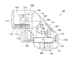
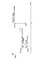
図1は、本発明の第1の実施の形態に係る照明装置の概略構成を示すブロック図である。この照明装置は、ストロボ装置100として構成される。図2は、ストロボ装置100の概略構成を示す図である。なお、図1と図2において、同一の要素については同じ符号を付している。
(First embodiment)
FIG. 1 is a block diagram showing a schematic configuration of a lighting device according to a first embodiment of the invention. This illumination device is configured as a strobe device 100 . FIG. 2 is a diagram showing a schematic configuration of the strobe device 100. As shown in FIG. In addition, in FIG.1 and FIG.2, the same code|symbol is attached|subjected about the same element.

ストロボ装置100は、不図示のカメラ本体に着脱可能に装着される本体部100aと、本体部100aに対して上下方向及び左右方向に回動可能に保持される発光部100bとを有している。なお、本実施の形態では、本体部100aにおける発光部100bと連結される側を上側として発光部100bの回動方向を定義する。ストロボ装置100は、マイクロコンピュータFPU(以下、ストロボマイコン)101を備えている。 The strobe device 100 has a body portion 100a detachably attached to a camera body (not shown), and a light emitting portion 100b held so as to be rotatable vertically and horizontally with respect to the body portion 100a. . Note that in the present embodiment, the rotation direction of the light emitting unit 100b is defined with the side of the main body 100a connected to the light emitting unit 100b being the upper side. The strobe device 100 includes a microcomputer FPU (hereinafter referred to as strobe microcomputer) 101 .

ストロボマイコン101は、ストロボ装置100全体の制御を司る。ストロボマイコン101は、例えば、CPU、ROM、RAM、入出力制御回路(I/Oコントロール回路)、マルチプレクサ、タイマ回路、EEPROM、A/D、およびD/Aコンバータを有するマイコン内蔵ワンチップIC回路である。 A strobe microcomputer 101 controls the strobe device 100 as a whole. The strobe microcomputer 101 is, for example, a one-chip IC circuit with a built-in microcomputer having a CPU, ROM, RAM, input/output control circuit (I/O control circuit), multiplexer, timer circuit, EEPROM, A/D, and D/A converter. be.

電池200は、ストロボ装置100の電源(VBAT)として機能する。昇圧回路102は、昇圧部102a、電圧検出に用いる抵抗102bおよび102c、並びにメインコンデンサ102dを有している。昇圧回路102は、昇圧部102aによって電池200の電圧を数百Vに昇圧し、メインコンデンサ102dに発光のための電気エネルギを蓄積させる。メインコンデンサ102dの充電電圧は抵抗102b、102cにより分圧され、分圧された電圧はストロボマイコン101のA/D変換端子に入力される。トリガー回路103は、放電管104を励起するためのパルス電圧を放電管104に印加する。発光制御回路105は、放電管104の発光の開始及び停止を制御する。放電管104は、トリガー回路103から印加される数KVのパルス電圧を受けて励起され、メインコンデンサ102dに充電された電気エネルギを用いて発光する。 Battery 200 functions as a power supply (VBAT) for strobe device 100 . The booster circuit 102 has a booster section 102a, resistors 102b and 102c used for voltage detection, and a main capacitor 102d. The booster circuit 102 boosts the voltage of the battery 200 to several hundreds of volts by the booster 102a, and stores electrical energy for light emission in the main capacitor 102d. The charging voltage of the main capacitor 102d is divided by the resistors 102b and 102c, and the divided voltage is input to the A/D conversion terminal of the strobe microcomputer 101. FIG. Trigger circuit 103 applies a pulse voltage to discharge tube 104 to excite discharge tube 104 . A light emission control circuit 105 controls the start and stop of light emission of the discharge tube 104 . The discharge tube 104 is excited by receiving a pulse voltage of several kilovolts applied from the trigger circuit 103, and emits light using the electrical energy charged in the main capacitor 102d.

フォトダイオード107は、放電管104から発せられる光を受光するセンサであり、直接またはグラスファイバー等を介して放電管104から発せられる光を受光して、その発光量に応じた検知出力(電流)を出力する。積分回路106は、フォトダイオード107の出力である電流を積分する。積分回路106の出力は、コンパレータ108の反転入力端子およびストロボマイコン101のA/Dコンバータ端子に入力される。コンパレータ108の非反転入力端子は、ストロボマイコン101内のD/Aコンバータ端子に接続され、コンパレータ108の出力端子はANDゲート109の入力端子の一方に接続される。ANDゲート109の入力端子の他方は、ストロボマイコン101の発光制御端子と接続され、ANDゲート109の出力端子は発光制御回路105に接続される。 The photodiode 107 is a sensor that receives the light emitted from the discharge tube 104. The photodiode 107 receives the light emitted from the discharge tube 104 directly or via a glass fiber or the like, and outputs a detection output (current) corresponding to the amount of light emitted. to output The integration circuit 106 integrates the current output from the photodiode 107 . The output of the integration circuit 106 is input to the inverting input terminal of the comparator 108 and the A/D converter terminal of the strobe microcomputer 101 . A non-inverting input terminal of the comparator 108 is connected to a D/A converter terminal in the strobe microcomputer 101 , and an output terminal of the comparator 108 is connected to one input terminal of the AND gate 109 . The other input terminal of the AND gate 109 is connected to the light emission control terminal of the strobe microcomputer 101 , and the output terminal of the AND gate 109 is connected to the light emission control circuit 105 .

入力部113は、電源スイッチ、ストロボ装置100の動作モードを設定するモード設定スイッチ、および各種パラメータを設定する設定ボタン等の操作部を有している。そして、ストロボマイコン101は、入力部113への入力に応じて各種処理を実行する。表示部114は、液晶装置や発光素子を有する。表示部114には、ストロボ装置100の各状態を示す情報が表示される。 The input unit 113 has operation units such as a power switch, a mode setting switch for setting the operation mode of the strobe device 100, and setting buttons for setting various parameters. The strobe microcomputer 101 executes various processes according to the input to the input unit 113 . The display unit 114 has a liquid crystal device and a light emitting element. Information indicating each state of the strobe device 100 is displayed on the display unit 114 .

ストロボ装置100の発光部100bは、主に、放電管104、反射傘110、光学パネル111を有し、照明用の光を発する。反射傘ユニット112は反射傘110を含む。発光部100bの配光角は、反射傘ユニット112の移動により変化し、発光部100bの照射方向は本体部100aからの回動により変化する。 A light emitting unit 100b of the strobe device 100 mainly includes a discharge tube 104, a reflector 110, and an optical panel 111, and emits light for illumination. Reflector unit 112 includes reflector 110 . The light distribution angle of the light emitting section 100b changes with movement of the reflector unit 112, and the irradiation direction of the light emitting section 100b changes with rotation from the main body section 100a.

ズーム駆動回路115は、ズーム検出部115aおよびズーム駆動部115bを備える。ズーム検出部115aは、エンコーダ等により、反射傘ユニット112と光学パネル111との相対位置に関する情報を検出する。ズーム駆動部115bは、モータによって反射傘ユニット112を移動させる。ストロボマイコン101は、カメラ本体を介して得た撮影レンズの焦点距離情報に応じて、反射傘ユニット112の駆動量を求める。 The zoom drive circuit 115 includes a zoom detection section 115a and a zoom drive section 115b. The zoom detector 115a detects information about the relative position between the reflector unit 112 and the optical panel 111 using an encoder or the like. The zoom driving section 115b moves the reflector unit 112 by a motor. The strobe microcomputer 101 obtains the drive amount of the reflector unit 112 according to the focal length information of the photographing lens obtained via the camera body.

反射傘110は、放電管104から発せられた光を反射させて所定の方向へ導く。光学パネル111等を含むズーム光学系は、放電管104と反射傘ユニット112との相対位置を変更可能に保持されている。反射傘ユニット112と光学パネル111との相対位置を変更することにより、ストロボ装置100のガイドナンバ及び配光角を変化させることができる。 Reflector 110 reflects the light emitted from discharge tube 104 and guides it in a predetermined direction. A zoom optical system including the optical panel 111 and the like is held so that the relative positions of the discharge tube 104 and the reflector unit 112 can be changed. By changing the relative position between the reflector unit 112 and the optical panel 111, the guide number and light distribution angle of the strobe device 100 can be changed.

端子116は、SCLK_S端子、MOSI_S端子、MISO_S端子、およびGND端子を備えている。SCLK_S端子は、カメラ本体とストロボ装置100の通信の同期をとるための端子である。MOSI_S端子は、カメラ本体からストロボ装置100にデータを送信するための端子である。MISO_S端子は、ストロボ装置100から送信されたデータを受信するための端子である。GND端子は、カメラ本体とストロボ装置100との両方をつなぐ。 Terminal 116 includes an SCLK_S terminal, a MOSI_S terminal, a MISO_S terminal, and a GND terminal. The SCLK_S terminal is a terminal for synchronizing communication between the camera body and the strobe device 100 . A MOSI_S terminal is a terminal for transmitting data from the camera body to the strobe device 100 . A MISO_S terminal is a terminal for receiving data transmitted from the strobe device 100 . The GND terminal connects both the camera body and the strobe device 100 .

冷却手段としての冷却部117は、光学パネル111を冷却するためのファンモジュールであり、ストロボマイコン101のFAN_PWM端子およびFAN_FG端子に接続されている。ストロボマイコン101は、PWM制御により冷却部117のファンの回転数を変化させ、出力する風量を変化させることができる。また、ストロボマイコン101へ回転数情報がフィードバックされることで、回転指示通りの回転数を維持することができる。 A cooling unit 117 as cooling means is a fan module for cooling the optical panel 111 and is connected to the FAN_PWM terminal and the FAN_FG terminal of the strobe microcomputer 101 . The strobe microcomputer 101 can change the rotation speed of the fan of the cooling unit 117 by PWM control to change the amount of air to be output. In addition, by feeding back rotation speed information to the strobe microcomputer 101, it is possible to maintain the rotation speed as instructed.

発光部温度検出部118(第1の温度取得手段)は、ストロボマイコン101と接続され、発光部100b内の放電管104からの光路を遮らない位置に配置される。発光部温度検出部118は、放電管104の発光で温度上昇する発光部100bの温度を検出(取得)する。すなわち、発光部温度検出部118は、発光部100bの近傍の第1の位置の温度を取得する。発光部温度検出部118で検出された温度情報はストロボマイコン101へ伝えられ、ストロボマイコン101の内蔵メモリに格納される。 The light-emitting portion temperature detector 118 (first temperature acquisition means) is connected to the strobe microcomputer 101 and arranged at a position that does not block the optical path from the discharge tube 104 in the light-emitting portion 100b. The light emitting part temperature detection part 118 detects (obtains) the temperature of the light emitting part 100 b whose temperature rises due to the light emission of the discharge tube 104 . That is, the light-emitting unit temperature detection unit 118 acquires the temperature at the first position near the light-emitting unit 100b. The temperature information detected by the light emitting unit temperature detection unit 118 is transmitted to the strobe microcomputer 101 and stored in the built-in memory of the strobe microcomputer 101 .

環境温度検出部119(第2の温度取得手段)は、ストロボ装置100の周囲の環境温度を検出する。環境温度検出部119は、ストロボマイコン101と接続され、本体部100a内の放電管104からの熱の影響が小さい位置に配置される。すなわち、環境温度検出部119は、発光部温度検出部118の配置位置よりも、発光部100bの温度変化の影響を受けにくい第2の位置の温度を取得する。発光部100bと第1の位置との空間距離よりも、発光部100bと第2の位置との空間距離の方が長い。なお、発光部100b以外にも発熱源がある場合、環境温度検出部119は発光部100b以外の発熱源からの熱の影響が小さい位置に配置されることが好ましい。環境温度検出部119で検出された温度情報はストロボマイコン101へ伝えられ、ストロボマイコン101の内蔵メモリに格納される。環境温度検出部119は、外装カバー(エンクロージャ)の持ち手とならない箇所に熱的に接続されていることが望ましい。なお、省スペース化のために本体部100a内の他の温度検出部により検出した温度を環境温度として扱ってもよい。 The environmental temperature detector 119 (second temperature acquisition means) detects the environmental temperature around the strobe device 100 . The ambient temperature detector 119 is connected to the strobe microcomputer 101 and arranged at a position where the influence of heat from the discharge tube 104 in the main body 100a is small. That is, the ambient temperature detection unit 119 acquires the temperature at the second position, which is less affected by the temperature change of the light emission unit 100b than the position where the light emission unit temperature detection unit 118 is arranged. The spatial distance between the light emitting section 100b and the second position is longer than the spatial distance between the light emitting section 100b and the first position. Note that if there is a heat source other than the light emitting unit 100b, the ambient temperature detection unit 119 is preferably arranged at a position where the influence of heat from the heat source other than the light emitting unit 100b is small. The temperature information detected by the environmental temperature detector 119 is transmitted to the strobe microcomputer 101 and stored in the built-in memory of the strobe microcomputer 101 . The environmental temperature detector 119 is desirably thermally connected to a portion of the exterior cover (enclosure) that does not serve as a handle. In order to save space, the temperature detected by another temperature detector in the main body 100a may be treated as the environmental temperature.

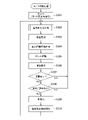
図3は、ストロボ側処理のフローチャートである。図3で、ストロボ装置100の発光に伴う動作を説明する。このストロボ側処理は、ストロボマイコン101において、ROMに格納されたプログラムをCPUがRAMに展開して実行することにより実現される。この処理は、入力部113に含まれる電源スイッチがONされてストロボマイコン101が動作可能となると開始される。 FIG. 3 is a flow chart of strobe-side processing. 3A and 3B, operations associated with light emission of the strobe device 100 will be described. This strobe-side processing is implemented in the strobe microcomputer 101 by the CPU developing a program stored in the ROM into the RAM and executing it. This processing is started when the power switch included in the input unit 113 is turned on and the strobe microcomputer 101 becomes operable.

まず、ステップS301で、ストロボマイコン101は、自身のメモリやポートの初期化を行う。ストロボマイコン101はまた、入力部113に含まれるスイッチの状態や予め設定された入力情報を読み込み、発光量の決め方や、発光タイミング等、様々な発光モードの設定を行う。ステップS302では、ストロボマイコン101は、温度差判定処理(図4で後述)を実行する。詳細は後述するが、この温度差判定処理では、発光部温度検出部118および環境温度検出部119によりそれぞれ検出された温度情報と、発光判定の結果とに基づいて、冷却部117の駆動が制御される。この温度差判定処理では、ストロボマイコン101は、取得した各温度情報と、温度差判定処理による判定結果と、発光判定の結果とを、自身に内蔵されるメモリに格納する。発光判定については図7で後述する。 First, in step S301, the strobe microcomputer 101 initializes its own memory and ports. The strobe microcomputer 101 also reads the states of the switches included in the input unit 113 and preset input information, and sets various light emission modes such as how to determine the light emission amount and light emission timing. In step S302, the strobe microcomputer 101 executes temperature difference determination processing (described later with reference to FIG. 4). Although the details will be described later, in this temperature difference determination process, the driving of the cooling unit 117 is controlled based on the temperature information detected by the light emitting unit temperature detecting unit 118 and the environmental temperature detecting unit 119, respectively, and the result of light emission determination. be done. In this temperature difference determination process, the strobe microcomputer 101 stores the obtained temperature information, the determination result of the temperature difference determination process, and the light emission determination result in its internal memory. Light emission determination will be described later with reference to FIG.

次に、ステップS303では、ストロボマイコン101は、昇圧回路102の動作を開始させてメインコンデンサ102dの充電を開始する。次に、ステップS304では、ストロボマイコン101は、不図示のカメラマイコンから端子116を介して取得した不図示の撮影レンズの焦点距離情報を、ストロボマイコン101の内蔵メモリに格納する。なお、以前に焦点距離情報を格納していた場合には、新たな焦点距離情報に更新される。ステップS305では、ストロボマイコン101は、ストロボ光の配光角が、上記取得した焦点距離情報に応じた範囲となるように、ズーム駆動回路115を制御して反射傘ユニット112を移動させる。なお、反射傘ユニット112を移動させる必要がない場合は、このステップを省略できる。 Next, in step S303, the strobe microcomputer 101 starts operating the booster circuit 102 to start charging the main capacitor 102d. Next, in step S304, the strobe microcomputer 101 stores the focal length information of the photographing lens (not shown) obtained from the camera microcomputer (not shown) through the terminal 116 in the built-in memory of the strobe microcomputer 101. FIG. If the focal length information was previously stored, it is updated with new focal length information. In step S305, the strobe microcomputer 101 controls the zoom drive circuit 115 to move the reflector unit 112 so that the light distribution angle of the strobe light falls within the range corresponding to the acquired focal length information. Note that this step can be omitted if there is no need to move the reflector unit 112 .

ステップS306では、ストロボマイコン101は、入力部113にて設定された発光モードに関する画像や取得した焦点距離情報に関する画像等を表示部114に表示する。この他、後述の温度差判定処理で冷却部117の駆動を開始したにも拘わらず、故障によって冷却部117の駆動を実行できない等のエラーが発生した場合には、ストロボマイコン101は、各種警告表示行う。ステップS307では、ストロボマイコン101は、メインコンデンサ102dの充電が完了しているか否かを判別する。メインコンデンサ102dの充電が完了していれば、ストロボマイコン101は、充電完了信号を不図示のカメラマイコンへ送信して処理をステップS308へ移行する。一方、メインコンデンサ102dの充電が完了していなければ、ストロボマイコン101は処理をステップS302へ戻す。 In step S<b>306 , the strobe microcomputer 101 displays an image related to the light emission mode set by the input unit 113 and an image related to the acquired focal length information on the display unit 114 . In addition, if an error occurs such that the cooling unit 117 cannot be driven due to a failure even though the cooling unit 117 has started to be driven in the later-described temperature difference determination process, the strobe microcomputer 101 issues various warnings. display. In step S307, the strobe microcomputer 101 determines whether charging of the main capacitor 102d is completed. If charging of the main capacitor 102d is completed, the strobe microcomputer 101 transmits a charging completion signal to the camera microcomputer (not shown), and the process proceeds to step S308. On the other hand, if charging of the main capacitor 102d is not completed, the flash microcomputer 101 returns the process to step S302.

ステップS308では、ストロボマイコン101は、不図示のカメラマイコンから本発光指示としての発光開始信号を受信したか否かを判別する。そしてストロボマイコン101は、発光開始信号を受信している場合は、処理をステップS309に進め、発光開始信号を受信していない場合は、処理をステップS302へ戻す。ステップS309では、ストロボマイコン101は、受信した発光開始信号に応じて発光制御回路105に発光指示を行う。これにより発光制御回路105は、発光指示に従って放電管104を発光させる。発光指示の終了後、ストロボマイコン101は、メインコンデンサ102dの電圧情報等、発光に関する情報をストロボマイコン101の内蔵メモリに格納し、ステップS310へ移行する。なお、ステップS309では、調光用のプリ発光と本発光のように一連する発光については、各発光が終了するごとにステップS302へ戻るのではなく、一連する発光の終了後にステップS302へ戻る。 In step S308, the strobe microcomputer 101 determines whether or not it has received a light emission start signal as a main light emission instruction from a camera microcomputer (not shown). If the strobe microcomputer 101 has received the light emission start signal, the process proceeds to step S309, and if the light emission start signal has not been received, the process returns to step S302. In step S309, the strobe microcomputer 101 instructs the light emission control circuit 105 to emit light according to the received light emission start signal. Thereby, the light emission control circuit 105 causes the discharge tube 104 to emit light according to the light emission instruction. After the light emission instruction is completed, the strobe microcomputer 101 stores information regarding light emission such as voltage information of the main capacitor 102d in the built-in memory of the strobe microcomputer 101, and proceeds to step S310. In step S309, for a series of light emission such as pre-light emission for dimming and main light emission, the process returns to step S302 after the series of light emission is completed instead of returning to step S302 each time each light emission ends.

ステップS310では、ストロボマイコン101は、連続発光等で発光による熱が加えられ続けても異常に発熱し過ぎることが無いよう発光や充電を制御する連続発光制御を開始する。連続発光制御の詳細については図7で後述する。この連続発光制御では、ストロボマイコン101は、後述する発光カウンタの値が初期状態から変化した時に演算を開始し、演算結果が初期状態に戻った時に終了する。つまり、ストロボマイコン101は、発光によって発生する熱の影響から保護する部位の温度を想定して、1回目の発光から対象部位の想定温度あるいはその代替となる発光カウンタの演算を開始する。そして、演算結果が初期状態と同じになるまで放熱する時間が経過するか、リセットがかかるまで、図3のストロボ側処理と並行して演算が続けられる。従って、連続発光制御と呼称しているものの、単発の発光に対しても連続発光制御(図7)と同様の処理が行われる。ストロボマイコン101は、連続発光制御を開始させた後、処理をステップS302へ戻す。 In step S310, the strobe microcomputer 101 starts continuous light emission control for controlling light emission and charging so as to prevent abnormally excessive heat generation even if the light continues to generate heat due to continuous light emission or the like. Details of the continuous light emission control will be described later with reference to FIG. In this continuous light emission control, the strobe microcomputer 101 starts calculation when the value of a light emission counter, which will be described later, changes from the initial state, and ends when the calculation result returns to the initial state. In other words, the strobe microcomputer 101 assumes the temperature of the part to be protected from the influence of heat generated by light emission, and starts calculating the assumed temperature of the target part from the first light emission or an alternative light emission counter. Then, the computation continues in parallel with the strobe-side processing in FIG. 3 until the heat dissipation time elapses until the computation result becomes the same as the initial state, or until the reset is applied. Therefore, although it is called continuous light emission control, the same process as continuous light emission control (FIG. 7) is performed for single light emission. After starting the continuous light emission control, the strobe microcomputer 101 returns the process to step S302.

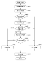
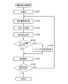
図4は、図3のステップS302で実行される温度差判定処理のフローチャートである。この温度差判定処理において、ストロボマイコン101は、本発明における制御手段に該当する。この温度差判定処理を概説すると、まず、ストロボマイコン101は、発光部温度検出部118と環境温度検出部119からの各温度情報の出力値の差である温度差Dを求める。そしてストロボマイコン101は、温度差Dと各閾値との比較により、冷却部117をどの程度の出力で駆動するか、あるいは駆動しないかを判定する。環境温度が上昇し過ぎると、冷却部117を駆動しても大きな冷却効果が見込めないことから、ストロボマイコン101は、冷却部117の非効率な動作を回避する。一方、ストロボマイコン101は、主に発光熱で発光部100bが温度上昇したと判断される場合には冷却部117の駆動によって発光部100bを効率よく冷却する。 FIG. 4 is a flow chart of the temperature difference determination process executed in step S302 of FIG. In this temperature difference determination process, the strobe microcomputer 101 corresponds to control means in the present invention. First, the strobe microcomputer 101 obtains the temperature difference D, which is the difference between the output values of each temperature information from the light emitting unit temperature detector 118 and the ambient temperature detector 119 . Then, the strobe microcomputer 101 compares the temperature difference D with each threshold value to determine with what output the cooling unit 117 should be driven or not. If the environmental temperature rises too much, driving the cooling unit 117 cannot expect a large cooling effect, so the strobe microcomputer 101 avoids inefficient operation of the cooling unit 117 . On the other hand, the strobe microcomputer 101 efficiently cools the light emitting unit 100b by driving the cooling unit 117 when it is determined that the temperature of the light emitting unit 100b has risen mainly due to the heat of emission.

ステップS401では、ストロボマイコン101は、発光部温度検出部118により検出された発光部100bの温度情報(以下、発光部温度Tfと称する)を取得し、取得した発光部温度Tfをストロボマイコン101の内蔵メモリに格納する。ステップS402では、ストロボマイコン101は、環境温度検出部119により検出された温度情報(以下、環境温度Tcと称する)を、本体部100aを介して取得し、取得した環境温度Tcをストロボマイコン101の内蔵メモリに格納する。 In step S401, the strobe microcomputer 101 acquires temperature information of the light emitting unit 100b detected by the light emitting unit temperature detection unit 118 (hereinafter referred to as the light emitting unit temperature Tf). Store in internal memory. In step S402, the flash microcomputer 101 acquires temperature information (hereinafter referred to as environmental temperature Tc) detected by the environmental temperature detection unit 119 via the main unit 100a, and the acquired environmental temperature Tc is sent to the flash microcomputer 101. Store in internal memory.

ステップS403では、ストロボマイコン101は、ステップS401で格納した取得結果である発光部温度Tfが閾値α以下であるか(Tf≦α)否かを判別する。ここで、閾値αは発光部100bを保護するために必要な上限温度と発光部温度検出部118の出力との相関関係から設定される。なお、閾値αは固定値であってもよい。ストロボマイコン101は、その判別の結果、Tf≦αであれば処理をステップS404へ進め、α<Tfであれば処理をステップS409へ進める。 In step S403, the strobe microcomputer 101 determines whether or not the light emitting unit temperature Tf, which is the obtained result stored in step S401, is equal to or less than the threshold value α (Tf≦α). Here, the threshold value α is set based on the correlation between the upper limit temperature required to protect the light emitting unit 100 b and the output of the light emitting unit temperature detection unit 118 . Note that the threshold α may be a fixed value. As a result of the determination, the flash microcomputer 101 advances the process to step S404 if Tf≦α, and advances the process to step S409 if α<Tf.

なお、起動初期状態における発光部温度検出部118の出力と環境温度検出部119の出力とに基づいて発光部温度検出部118の出力をオフセットしてもよい。そして、このようにオフセットした値を、温度差判定処理(図4)で冷却部117の駆動を制御する際に発光部温度検出部118の出力として用いてもよい(つまり発光部温度Tfとして扱ってもよい)。これにより、起動初期状態における温度検出部118、119間の出力差をキャンセルすることができる。 The output of the light emitting part temperature detecting part 118 may be offset based on the output of the light emitting part temperature detecting part 118 and the output of the environmental temperature detecting part 119 in the initial startup state. Then, the value offset in this way may be used as the output of the light emitting part temperature detecting part 118 when controlling the driving of the cooling part 117 in the temperature difference determination process (FIG. 4) (that is, treated as the light emitting part temperature Tf may be used). This makes it possible to cancel the output difference between the temperature detection units 118 and 119 in the initial startup state.

ステップS404では、ストロボマイコン101は、ステップS401で取得した発光部温度TfとステップS402で取得した取得結果である環境温度Tcとの差である温度差Dを演算する(D=Tf-Tc)。そしてストロボマイコン101は、演算した温度差Dをストロボマイコン101の内蔵メモリに格納する。ステップS405では、ストロボマイコン101は、ステップS404で格納した温度差Dと、ストロボマイコン101の内蔵メモリに格納されている閾値(閾値β、γ、δ)とを比較し、比較結果によって処理を分岐させる。閾値β、γ、δの大小関係は、β<γ<δである。 In step S404, the strobe microcomputer 101 calculates a temperature difference D, which is the difference between the light-emitting unit temperature Tf obtained in step S401 and the ambient temperature Tc obtained in step S402 (D=Tf−Tc). Then, the strobe microcomputer 101 stores the calculated temperature difference D in the built-in memory of the strobe microcomputer 101 . In step S405, the strobe microcomputer 101 compares the temperature difference D stored in step S404 with the thresholds (thresholds β, γ, δ) stored in the built-in memory of the strobe microcomputer 101, and branches the processing depending on the comparison result. Let The magnitude relationship between the thresholds β, γ, and δ is β<γ<δ.

その比較の結果、ストロボマイコン101は、D<βである場合は、処理をステップS408に進め、β≦D<γである場合は、処理をステップS406に進め、γ≦Dである場合は、処理をステップS409に進める。なお、比較結果は内蔵メモリに格納される。ステップS406では、ストロボマイコン101は、発光判定結果を取得する。発光判定結果は、発光部100bの発光の有無(発光有り、発光無し)を示す情報であり、後述する図7のステップS704の発光判定処理により生成される。発光判定結果は、発光部温度Tfないし温度差Dが、放電管104の発光に起因して生じたものかどうかを判断する尺度となる。発光判定結果を参照することで、温度差Dに基づく冷却部117の駆動制御の信頼性が高まる。 As a result of the comparison, the flash microcomputer 101 advances the process to step S408 if D<β, advances the process to step S406 if β≦D<γ, and advances the process to step S406 if γ≦D. The process proceeds to step S409. The comparison result is stored in the built-in memory. In step S406, the strobe microcomputer 101 acquires the light emission determination result. The light emission determination result is information indicating whether or not the light emitting unit 100b emits light (light emission, no light emission), and is generated by the light emission determination process in step S704 of FIG. 7, which will be described later. The light emission determination result serves as a measure for determining whether or not the light emission portion temperature Tf or the temperature difference D is caused by the light emission of the discharge tube 104 . By referring to the light emission determination result, the reliability of drive control of the cooling unit 117 based on the temperature difference D is increased.

ステップS407では、ストロボマイコン101は、ステップS406で取得した発光判定結果が、発光有りを示すか否かを判別する。そしてストロボマイコン101は、発光判定結果が、発光有りを示す場合は、処理をステップS409に進め、発光判定結果が、発光無しを示す場合は、処理をステップS408に進める。 In step S407, the strobe microcomputer 101 determines whether or not the light emission determination result obtained in step S406 indicates that light has been emitted. Then, if the light emission determination result indicates that there is light emission, the strobe microcomputer 101 advances the process to step S409, and if the light emission determination result indicates that there is no light emission, advances the process to step S408.

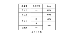
図5は、温度差Dと発光判定結果とに基づく冷却部117の駆動出力の設定例を示す図である。まず、温度差領域を次のように分ける。温度差DがD<βに属する温度差領域を第1の領域とする。温度差Dがβ≦D<γに属する温度差領域を第2の領域とする。温度差Dがγ≦Dに属する温度差領域を第3の領域とする。温度差領域の大小関係は、第1の領域<第2の領域<第3の領域である。ストロボマイコン101は、基本的には、温度差Dがどの領域に属するかによって、PWM信号によって冷却部117を駆動する際のDutyを異ならせると共に、発光判定結果に応じてさらに細かくDutyを設定する。 FIG. 5 is a diagram showing a setting example of the driving output of the cooling unit 117 based on the temperature difference D and the light emission determination result. First, the temperature difference regions are divided as follows. A temperature difference region in which the temperature difference D falls within D<β is defined as a first region. A temperature difference region in which the temperature difference D satisfies β≦D<γ is defined as a second region. A temperature difference region in which the temperature difference D satisfies γ≦D is defined as a third region. The magnitude relationship of the temperature difference areas is first area<second area<third area. The strobe microcomputer 101 basically varies the duty when driving the cooling unit 117 by the PWM signal depending on which region the temperature difference D belongs to, and further finely sets the duty according to the light emission determination result. .

図5に例示されるように、温度差Dが閾値β未満で第1の領域に属する場合は、Dutyは0%に設定される(つまり駆動停止)。温度差Dが閾値β以上γ未満で第2の領域に属する場合、発光判定結果が発光無しを示せばDutyは0%に設定され、発光判定結果が発光有りを示せばDutyは40%に設定される。温度差Dが、第3の領域のうち閾値δ未満の領域に属する場合、Dutyは60%に設定される。温度差Dが、第3の領域のうち閾値δ以上の領域に属する場合、Dutyは80%に設定される。 As illustrated in FIG. 5, when the temperature difference D is less than the threshold value β and belongs to the first region, the duty is set to 0% (that is, drive is stopped). When the temperature difference D is greater than or equal to the threshold value β and less than γ and belongs to the second region, if the light emission determination result indicates no light emission, the duty is set to 0%, and if the light emission determination result indicates the presence of light emission, the duty is set to 40%. be done. Duty is set to 60% when the temperature difference D belongs to a region less than the threshold value δ among the third regions. When the temperature difference D belongs to the threshold value δ or more among the third regions, the duty is set to 80%.

図6は、発光部温度Tfと温度差Dと発光判定結果とに応じたDuty設定の具体例を示す図である。図6の例では、発光部温度Tfが閾値αを超えない時点t1から発光部温度Tfが閾値αを超える時点t2へ遷移した場合の、冷却部117の出力変化を示している。 FIG. 6 is a diagram showing a specific example of duty setting according to the light emitting unit temperature Tf, the temperature difference D, and the light emission determination result. The example of FIG. 6 shows a change in the output of the cooling unit 117 when the light emitting unit temperature Tf transitions from time t1 at which the light emitting unit temperature Tf does not exceed the threshold α to time t2 at which the light emitting unit temperature Tf exceeds the threshold α.

時点t1では、発光部温度Tfが閾値αを超えていないので、処理はステップS403からステップS404に移行する。そのため、冷却部117を駆動するDutyは温度差Dに基づき制御される。しかし、時点t2では、発光部温度Tfが閾値αを超えるので、処理はステップS403からステップS409に移行する。この場合、発光部100bを保護することを優先し、ストロボマイコン101は、冷却部117の駆動出力を上限まで引き上げる。つまり、ステップS403からステップS409に移行した場合のステップS409では、ストロボマイコン101は、冷却部117を最大出力であるDuty100%で駆動する。 At time t1, the light-emitting unit temperature Tf does not exceed the threshold α, so the process proceeds from step S403 to step S404. Therefore, the duty for driving the cooling unit 117 is controlled based on the temperature difference D. FIG. However, at time t2, the light-emitting unit temperature Tf exceeds the threshold α, so the process proceeds from step S403 to step S409. In this case, priority is given to protecting the light emitting unit 100b, and the strobe microcomputer 101 raises the drive output of the cooling unit 117 to the upper limit. That is, in step S409 when the process proceeds from step S403 to step S409, the strobe microcomputer 101 drives the cooling unit 117 at a maximum output of 100% duty.

なお、S403→S409に移行した場合のDutyは、100%に限らない。例えば、温度差Dと発光判定結果とに応じて冷却部117を駆動する際の最も高い出力と同等以上の出力で、冷却部117を駆動してもよい。図5の例によれば、Tf≦αの場合に温度差Dと発光判定結果とに応じて設定され得るDutyの最高値はDuty80%であるので、S403→S409に移行した場合、Duty80%と同等以上の出力で、冷却部117を駆動してもよい。更に発光制限を併用することで、発光部100bの温度上昇を抑制してもよい。発光制限は、発光を禁止させる間隔(以下、最短発光間隔)を長くする制御である。ストロボマイコン101は、α<Tfの場合には、Tf≦αの場合よりも、発光部100bの発光間隔を長くする。図6の例では、発光制限の併用は、α<Tfとなる時点t2に実施されるが、閾値αを超えない時点t1においても発光制限を併用してもよい。発光制限は、放電管104の発光によって発生する熱の影響から発光部100bや光学パネル111を保護するのに有効である。 Note that the duty at the time of shifting from S403 to S409 is not limited to 100%. For example, the cooling unit 117 may be driven with an output equal to or greater than the highest output when driving the cooling unit 117 according to the temperature difference D and the light emission determination result. According to the example of FIG. 5, the maximum value of Duty that can be set according to the temperature difference D and the light emission determination result when Tf≦α is 80%. The cooling unit 117 may be driven with an equivalent or higher output. Furthermore, the temperature rise of the light emitting section 100b may be suppressed by using light emission restriction. Light emission restriction is control to lengthen the interval for which light emission is prohibited (hereinafter referred to as the shortest light emission interval). When α<Tf, the strobe microcomputer 101 makes the light emission interval of the light emitting unit 100b longer than when Tf≦α. In the example of FIG. 6, emission restriction is used together at time t2 when α<Tf, but emission restriction may be used together at time t1 at which threshold α is not exceeded. Light emission restriction is effective in protecting the light emitting section 100b and the optical panel 111 from the influence of heat generated by the light emission of the discharge tube 104. FIG.

図5、図6の例を踏まえて、図4の流れを改めてまとめると次のようになる。ステップS403でα<Tfの場合には、上述したように、ステップS409で、ストロボマイコン101は、温度差Dの大きさに拘わらず、冷却部117をDuty100%で駆動する。Tf≦αであり且つ、ステップS405でD<βである場合は、ステップS408で、ストロボマイコン101は、冷却部117の駆動を停止する。Tf≦αであり、ステップS405でβ≦D<γであり且つ、ステップS407で発光判定結果=発光無しの場合は、ステップS408で、ストロボマイコン101は、冷却部117の駆動を停止する。Tf≦αであり、ステップS405でβ≦D<γであり且つ、ステップS407で発光判定結果=発光有りの場合は、ストロボマイコン101は、ステップS409で、Duty40%で冷却部117を駆動する。Tf≦αであり且つ、ステップS405でγ≦Dである場合、ステップS409では、ストロボマイコン101は、γ≦D<δであればDuty60%で、δ≦DであればDuty80%で、冷却部117を駆動する。 Based on the examples of FIGS. 5 and 6, the flow of FIG. 4 can be summarized as follows. If α<Tf in step S403, the flash microcomputer 101 drives the cooling unit 117 at 100% duty regardless of the temperature difference D in step S409, as described above. If Tf≦α and D<β in step S405, the strobe microcomputer 101 stops driving the cooling unit 117 in step S408. If Tf≦α, β≦D<γ in step S405, and light emission determination result=no light emission in step S407, the strobe microcomputer 101 stops driving the cooling unit 117 in step S408. If Tf≦α, β≦D<γ in step S405, and light emission determination result=light emission in step S407, the strobe microcomputer 101 drives the cooling unit 117 at a duty of 40% in step S409. If Tf≤α and γ≤D in step S405, in step S409, the strobe microcomputer 101 sets the duty to 60% if γ≤D<δ, and to the duty of 80% if δ≤D. 117.

図5からわかるように、γ≦Dの場合、発光無しであってもDutyは0%にならず、すなわち冷却部117の駆動は停止されない。これは、連続発光後に発光カウンタ(図7で後述)がリセットされた場合を考慮したためである。例えば、電池を外した等によって発光カウンタがリセットされた場合、本来であれば発光判定が有りとなるべきであっても、発光無しと判定される場合があることから、冷却部117の駆動を確保するためである。 As can be seen from FIG. 5, when γ≦D, the duty does not become 0% even if no light is emitted, that is, the driving of the cooling unit 117 is not stopped. This is because a case where a light emission counter (described later in FIG. 7) is reset after continuous light emission is considered. For example, when the light emission counter is reset due to removal of the battery, etc., the cooling unit 117 is not driven because it may be determined that there is no light emission even though light emission should normally be determined. This is to ensure

ステップS408またはステップS409の後、ストロボマイコン101は、ステップS410で、ステップS403、S405、S407での判別結果をストロボマイコン101の内蔵メモリに格納し、図4の温度差判定処理を終了する。 After step S408 or step S409, the strobe microcomputer 101 stores the determination results of steps S403, S405, and S407 in the built-in memory of the strobe microcomputer 101 in step S410, and terminates the temperature difference determination process in FIG.

図7は、連続発光制御処理のフローチャートである。この処理は、ストロボマイコン101において、ROMに格納されたプログラムをCPUがRAMに展開して実行することにより実現される。図3のステップS310で放電管104が発光すると、ストロボマイコン101は、図7に示す連続発光制御処理を開始し、図3のストロボ側処理と並行して実行する。 FIG. 7 is a flowchart of continuous light emission control processing. This process is implemented by the CPU developing a program stored in the ROM in the RAM and executing the program in the strobe microcomputer 101 . When the discharge tube 104 emits light in step S310 of FIG. 3, the strobe microcomputer 101 starts the continuous light emission control process shown in FIG. 7 and executes it in parallel with the strobe side process of FIG.

まず、ステップS701では、ストロボマイコン101は、連続発光制御に関する設定の初期化を行う。ストロボマイコン101は、予め設定された入力情報及びパラメータの読み込みを行う。なお、図3のステップS301で既に読み込みを行っている場合は、このステップを省略できる。 First, in step S701, the strobe microcomputer 101 initializes settings related to continuous light emission control. The strobe microcomputer 101 reads preset input information and parameters. Note that this step can be omitted if reading has already been performed in step S301 of FIG.

ステップS702では、ストロボマイコン101は、発光の際の放電管104の発光量情報を取得し、取得した発光量情報をストロボマイコン101の内蔵メモリに格納する。ステップS703にてストロボマイコン101は、連続発光処理用の演算として、ステップS404にて格納した温度差Dに基づいてカウンタ積算量Cの演算を行う。カウンタ積算量Cは、式1によって算出される。
C=(FL×ε×n-T×M)×(ζ×D+1)・・・(1)
In step S<b>702 , the strobe microcomputer 101 acquires information on the amount of light emitted from the discharge tube 104 during light emission, and stores the acquired information on the amount of light emitted in the built-in memory of the strobe microcomputer 101 . In step S703, the strobe microcomputer 101 calculates the counter integrated amount C based on the temperature difference D stored in step S404 as a calculation for continuous light emission processing. The counter integrated amount C is calculated by Equation (1).
C=(FL×ε×n−T×M)×(ζ×D+1) (1)

ここで、FLは発光量情報、ε及びζは調整用係数、nは発光回数、Tは減算を行う時間間隔、Mは減算量、Dは温度差である。式1によれば、ストロボマイコン101は、例えば、ステップS702で取得した発光量情報に対して、演算レンジ調整用の係数を設定し、それらを発光毎に積算していく。減算については所定の時間毎に所定量の減算を行う。このように積算した発光カウンタに対して、温度差Dに応じた値を積算することで、温度差が大きい場合に発光カウンタの積算量が増加し、発光カウンタに実温度による状態の変化を加味することが出来る。発光部100bの発光によって、式1の発光量情報FLおよび発光回数nが0(ゼロ)からプラス値に変わり、カウンタ積算量Cの積算が開始される。従って、発光カウンタは、発光に起因してカウントされる。 Here, FL is light emission amount information, ε and ζ are adjustment coefficients, n is the number of times of light emission, T is the time interval for subtraction, M is the amount of subtraction, and D is the temperature difference. According to Equation 1, the strobe microcomputer 101 sets coefficients for adjusting the calculation range for the light emission amount information acquired in step S702, and integrates them for each light emission. As for the subtraction, a predetermined amount of subtraction is performed every predetermined time. By accumulating a value corresponding to the temperature difference D with respect to the light emission counter thus accumulated, the accumulated amount of the light emission counter increases when the temperature difference is large, and changes in the state due to the actual temperature are added to the light emission counter. can do Due to the light emission of the light emitting unit 100b, the light emission amount information FL and the number of light emission times n in Equation 1 change from 0 (zero) to a positive value, and the integration of the counter integrated amount C is started. Therefore, the light emission counter is counted due to light emission.

具体的には、カウンタ積算量Cは、発光部100bの「発光量×発光回数」に応じて大きくなる。カウンタ積算量Cは、発光部100bの発光後の時間経過が長いと小さくなる。カウンタ積算量Cは、温度差Dが大きいと大きくなる。カウンタ積算量Cの演算結果は、ストロボマイコン101の内蔵メモリに格納される。 Specifically, the counter integrated amount C increases according to "light emission amount×number of times of light emission" of the light emitting unit 100b. The counter integrated amount C becomes smaller as the time elapses after the light emission of the light emitting unit 100b is longer. The counter integrated amount C increases as the temperature difference D increases. The calculation result of the counter integrated amount C is stored in the built-in memory of the strobe microcomputer 101 .

次に、ステップS704では、判定手段としてのストロボマイコン101は、発光判定処理を実行する。すなわち、ストロボマイコン101は、カウンタ積算量Cが所定値Ttを超えている(Tt<C)か否かを判別し、その判別の結果を、発光判定結果として生成する。Tt<Cの場合に発光有り、Tt≧Cの場合に発光無し、という判定結果が生成される。生成された発光判定結果(発光有り/発光無し)は、ストロボマイコン101の内蔵メモリに格納される。 Next, in step S704, the strobe microcomputer 101 as determination means executes light emission determination processing. That is, the strobe microcomputer 101 determines whether or not the counter integrated amount C exceeds a predetermined value Tt (Tt<C), and generates the determination result as the light emission determination result. A judgment result is generated that light is emitted when Tt<C, and no light is emitted when Tt≧C. The generated light emission determination result (light emission/no light emission) is stored in the built-in memory of the strobe microcomputer 101 .

なお、発光の有無の判定処理は、この例に限定されない。例えば、単位時間内の発光に伴って立てたビットによって発光の有無を判定してもよい。このビットは、発光後、所定時間が経過するまで立ち続ける。従って、ストロボマイコン101は、直近の所定時間内で発光部100bの発光が1回でもあれば「発光有り」、発光が1回もなければ「発光無し」と判定してもよい。 Note that the processing for determining whether or not light is emitted is not limited to this example. For example, the presence or absence of light emission may be determined by a bit set in accordance with light emission within a unit time. This bit remains on until a predetermined time elapses after light emission. Therefore, the strobe microcomputer 101 may determine "light emission" if the light emission unit 100b emits light even once within the most recent predetermined time, and "no light emission" if the light emission does not occur even once.

なお、所定値Ttは固定値でもよい。しかし、所定値Ttは、閾値α(S403)と連動して設定されてもよい。この場合、発光制限を実施する際の最短発光間隔を段階的に延長させて、冷却制御と発光制限制御とにより発熱抑制効果を高めることができる。例えば、ストロボマイコン101は、発光判定結果が発光有りを示す場合は、発光判定結果が発光無しを示す場合よりも、最短発光間隔を延長させる。 Note that the predetermined value Tt may be a fixed value. However, the predetermined value Tt may be set in conjunction with the threshold α (S403). In this case, the shortest light emission interval when light emission is restricted can be extended step by step, and the effect of suppressing heat generation can be enhanced by cooling control and light emission restriction control. For example, the strobe microcomputer 101 extends the shortest light emission interval when the light emission determination result indicates the presence of light emission compared to when the light emission determination result indicates the absence of light emission.

ステップS705では、ストロボマイコン101は、ステップS309における本発光時からズーム位置の変化がないか否かを判別する。そして、ズーム位置の変化がない場合は、ストロボマイコン101は、処理をステップS707に進める。しかし、ズーム位置の変化がある場合は、ストロボマイコン101は、ステップS706で、ズーム位置変更処理を行う。ストロボマイコン101は対応するズーム位置ごとに閾値を記憶部に格納している。このズーム位置変更処理は、ズーム位置が変更されたことに応じて、カウンタ積算量Cを調整するための処理である。これにより、大きな閾値を設定されたズーム位置と小さな閾値を設定されたズーム位置間との間でズーム移動させた場合に、各閾値に対するカウンタ積算量Cの積算比率を均一化できる。ズーム位置変更前の閾値をSP、変更後の閾値をSAとすると、カウンタ積算量Cは、式2で変換される。
C=C×SA/SP・・・(式2)
In step S705, the strobe microcomputer 101 determines whether or not the zoom position has changed since the main light emission in step S309. Then, if there is no change in the zoom position, the strobe microcomputer 101 advances the process to step S707. However, if there is a change in the zoom position, the strobe microcomputer 101 performs zoom position change processing in step S706. The strobe microcomputer 101 stores a threshold in a storage unit for each corresponding zoom position. This zoom position change process is a process for adjusting the counter integrated amount C in accordance with the change of the zoom position. As a result, when zooming is performed between a zoom position where a large threshold is set and a zoom position where a small threshold is set, the integration ratio of the counter integrated amount C with respect to each threshold can be made uniform. Assuming that the threshold value before the zoom position change is SP and the threshold value after the change is SA, the counter integrated amount C is converted by Equation (2).
C=C×SA/SP (Formula 2)

ズーム位置変更処理後、ストロボマイコン101は、ストロボマイコン101の内蔵メモリに処理結果を格納する。ステップS706の後、ストロボマイコン101は、処理をステップS707に進める。ステップS707では、ストロボマイコン101は、各種演算結果及びパラメータをストロボマイコン101の内蔵メモリに格納する。なお、既に格納が済んでいる場合はこのステップを省略してもよい。次に、ステップS708では、ストロボマイコン101は、カウンタ積算量Cが初期状態に戻っているか否かを判別する。上記式1で算出されるC値が0(ゼロ)になると、カウンタ積算量Cが初期状態に戻ったと判別される。例えば、最後の発光後、時間が経過して「-T×M」の減算項の効果によりC値が0になる。あるいは、電源投入時等には、C値は0になる。このような場合、カウンタ積算量Cが初期状態に戻ったと判別される。 After the zoom position change processing, the strobe microcomputer 101 stores the processing result in the built-in memory of the strobe microcomputer 101 . After step S706, the strobe microcomputer 101 advances the process to step S707. In step S707, the strobe microcomputer 101 stores various calculation results and parameters in the built-in memory of the strobe microcomputer 101. FIG. Note that this step may be omitted if the data has already been stored. Next, in step S708, the strobe microcomputer 101 determines whether or not the counter integrated amount C has returned to the initial state. When the C value calculated by Equation 1 above becomes 0 (zero), it is determined that the counter integrated amount C has returned to the initial state. For example, after the last light emission, the C value becomes 0 due to the effect of the "-TxM" subtraction term as time elapses. Alternatively, the C value becomes 0 when the power is turned on. In such a case, it is determined that the counter integrated amount C has returned to the initial state.

カウンタ積算量Cが初期状態に戻っていない場合は、ストロボマイコン101は、処理をステップS702に戻す。カウンタ積算量Cが初期状態に戻っている場合は、ストロボマイコン101は、図7に示す連続発光制御処理を終了する。 If the counter integrated amount C has not returned to the initial state, the strobe microcomputer 101 returns the process to step S702. If the counter integrated amount C has returned to the initial state, the strobe microcomputer 101 terminates the continuous light emission control process shown in FIG.

本実施の形態によれば、ストロボマイコン101は、発光部温度Tfと環境温度Tcと発光判定の結果とに基づいて、冷却部117の駆動を制御し、具体的には、温度差Dと発光有無とに基づいて、冷却部117の駆動を制御する。基本的には、ストロボマイコン101は、温度差Dが属する領域に応じて、冷却部117を駆動する際の出力の大きさ(Duty)を異ならせるので(図5)、温度差Dに応じた適切な冷却を実現できる。また、ストロボマイコン101は、温度差Dが属する領域によっては、発光判定の結果が発光有りを示すか発光無しを示すかによって、Dutyを異ならせる。例えば、β≦D<γの場合は、発光判定結果が発光無しを示せばDutyは0%(停止)に設定され、発光判定結果が発光有りを示せばDutyは40%に設定される。これにより、直近の発光部100bの発光による昇温への影響を考慮した冷却制御が可能となるので、非効率な駆動を回避すると共に効率的な冷却を実現できる。よって、発光部の昇温を適切に抑制することができる。 According to the present embodiment, the strobe microcomputer 101 controls driving of the cooling unit 117 based on the light emitting unit temperature Tf, the environmental temperature Tc, and the result of light emission determination. The driving of the cooling unit 117 is controlled based on the presence/absence. Basically, the strobe microcomputer 101 varies the output magnitude (Duty) when driving the cooling unit 117 according to the region to which the temperature difference D belongs (FIG. 5). Appropriate cooling can be achieved. Further, the strobe microcomputer 101 varies the duty depending on whether the result of the light emission determination indicates that light is emitted or that light is not emitted depending on the region to which the temperature difference D belongs. For example, if β≦D<γ, the duty is set to 0% (stop) if the light emission determination result indicates no light emission, and is set to 40% if the light emission determination result indicates the presence of light emission. As a result, cooling control can be performed in consideration of the effect of light emission from the nearest light emitting unit 100b on temperature rise, so that inefficient driving can be avoided and efficient cooling can be achieved. Therefore, it is possible to appropriately suppress the temperature rise of the light emitting section.

また、α<Tfの場合には、温度差Dの大きさに拘わらず冷却部117の駆動出力がDuty100%に設定されるので(S403→S409)、発光部100bの保護が優先される。また、γ≦Dの場合、発光無しであっても冷却部117の駆動は停止されないので(S405→S409)、発光部100bの冷却が確保される。 Further, when α<Tf, the drive output of the cooling unit 117 is set to 100% duty regardless of the magnitude of the temperature difference D (S403→S409), so protection of the light emitting unit 100b is prioritized. Further, when γ≦D, the driving of the cooling unit 117 is not stopped even if no light is emitted (S405→S409), so cooling of the light emitting unit 100b is ensured.

なお、ストロボマイコン101は、マイコン内蔵ワンチップIC回路構成であるが、各機能に応じて専用のマイコン・メモリ等を設けてもよい。また、冷却部117は、ファンモジュールとして説明したが、ポンプ等の同等の機能を持つ冷却モジュールであっても構わない。なお、説明した各フローチャートはあくまで一例であって、不都合がなければ各フローチャートと異なる順序で各ステップを実行してもよい。 The strobe microcomputer 101 has a one-chip IC circuit configuration with a built-in microcomputer, but a dedicated microcomputer memory or the like may be provided according to each function. Also, although the cooling unit 117 has been described as a fan module, it may be a cooling module having an equivalent function such as a pump. Each flow chart described above is merely an example, and steps may be executed in an order different from that of each flow chart if there is no problem.

なお、β≦D<γであり且つ、発光判定結果=発光無しの場合、冷却部117の駆動は停止されるとしたが(S407→S408)、β≦D<γであり且つ、発光判定結果=発光有りの場合のDuty(40%)より低いDutyで冷却部117を駆動してもよい。 Note that when β≦D<γ and the light emission determination result=no light emission, driving of the cooling unit 117 is stopped (S407→S408), but β≦D<γ and the light emission determination result = The cooling unit 117 may be driven with a duty lower than the duty (40%) when light is emitted.

(第2の実施の形態)
第1の実施の形態では、第2の位置は、第1の位置よりも、発光部100bの温度変化の影響を受けにくい位置であった。しかし、第2の位置は、ストロボ装置100内の位置でなくてもよく、ストロボ装置100に接続されたカメラ本体内または外部電源装置内にあってもよい。本発明の第2の実施の形態では、ストロボ装置100に接続されている機器から環境温度を取得する点が第1の実施形態と異なる。その他の構成は第1の実施の形態と同様である。図1に代えて図8を用いて本実施の形態を説明する。
(Second embodiment)
In the first embodiment, the second position is less susceptible to temperature changes in the light emitting section 100b than the first position. However, the second location need not be a location within strobe device 100, but may be within a camera body connected to strobe device 100 or within an external power supply. The second embodiment of the present invention differs from the first embodiment in that the environmental temperature is acquired from a device connected to the strobe device 100. FIG. Other configurations are the same as those of the first embodiment. This embodiment will be described with reference to FIG. 8 instead of FIG.

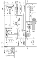
図8は、ストロボ装置100を含むカメラシステムの概略構成を示すブロック図である。このカメラシステムにおいて、図1と同じ構成要素には同じ符号が付してある。ストロボ装置100には、カメラ本体300、外部電源装置500が接続されている。ストロボマイコン101は、カメラ本体300または外部電源装置500から環境温度を取得する。ストロボ装置100の端子120に外部電源装置500が電気的に接続される。ストロボ装置100の端子116にカメラ本体300が電気的に接続される。カメラ本体300の端子304にレンズユニット400が電気的に接続される。 FIG. 8 is a block diagram showing a schematic configuration of a camera system including strobe device 100. As shown in FIG. In this camera system, the same reference numerals are assigned to the same components as in FIG. A camera body 300 and an external power supply device 500 are connected to the strobe device 100 . The strobe microcomputer 101 acquires the environmental temperature from the camera body 300 or the external power supply device 500 . An external power supply device 500 is electrically connected to the terminal 120 of the strobe device 100 . A camera body 300 is electrically connected to the terminal 116 of the strobe device 100 . A terminal 304 of the camera body 300 is electrically connected to the lens unit 400 .

端子120は、ストロボ装置100と外部電源装置500の制御を行うための信号の入出力を行う信号端子(SEH)と、メインコンデンサ102dに給電を行うための高圧電力入力端子(HV)とを含む。また、端子120は、ストロボ装置100と外部電源装置500の双方をつなぐGND端子も含む。 The terminal 120 includes a signal terminal (SEH) for inputting and outputting signals for controlling the strobe device 100 and the external power supply device 500, and a high voltage power input terminal (HV) for supplying power to the main capacitor 102d. . Terminal 120 also includes a GND terminal that connects both strobe device 100 and external power supply device 500 .

次に、カメラ本体300の構成について説明する。マイクロコンピュータCCPU(以下、カメラマイコン)301は、カメラ本体300の各部を制御する。カメラマイコン301は、例えばCPU、ROM、RAM、入出力制御回路(I/Oコントロール回路)、マルチプレクサ、タイマ回路、EEPROM、A/D、D/Aコンバータ等を含むマイコン内蔵ワンチップIC回路である。カメラマイコン301は、カメラシステムの制御をソフトウェアで行い、各種の条件判定を行う。 Next, the configuration of the camera body 300 will be described. A microcomputer CCPU (hereinafter referred to as camera microcomputer) 301 controls each part of the camera body 300 . The camera microcomputer 301 is a one-chip IC circuit with built-in microcomputer including, for example, CPU, ROM, RAM, input/output control circuit (I/O control circuit), multiplexer, timer circuit, EEPROM, A/D, D/A converter, etc. . The camera microcomputer 301 performs software control of the camera system and performs various condition determinations.

撮像素子302は、赤外カットフィルタやローパスフィルタ等を含むCCD、CMOS等の撮像素子であり、後述のレンズ群402によって撮影時に被写体像が結像される。撮像回路303は、例えばゲイン切り換え回路、A/D変換器、タイミングジェネレータ、信号処理回路等を含み、各種撮像処理を行う。 The imaging element 302 is an imaging element such as a CCD or CMOS including an infrared cut filter, a low-pass filter, and the like. The imaging circuit 303 includes, for example, a gain switching circuit, an A/D converter, a timing generator, a signal processing circuit, etc., and performs various imaging processes.

端子304は、カメラ本体300とレンズユニット400の通信の同期をとるためのSCLK_L端子、レンズユニット400にデータを送信するMOSI_L端子、レンズユニット400から送信されたデータを受信するMISO_L端子を含む。また、端子304は、カメラ本体300とレンズユニット400との両方をつなぐGND端子も含む。 A terminal 304 includes an SCLK_L terminal for synchronizing communication between the camera body 300 and the lens unit 400 , a MOSI_L terminal for transmitting data to the lens unit 400 , and a MISO_L terminal for receiving data transmitted from the lens unit 400 . Terminal 304 also includes a GND terminal that connects both camera body 300 and lens unit 400 .

温度検出部305は、カメラ本体300内の温度を検出する。撮像系の温度の影響を受けにくいように、温度検出部305は、撮像素子302や撮像回路303から離れた箇所(トップカバー等)に配置することが望ましい。温度検出部305で検出された温度情報はカメラマイコン301へ伝えられ、カメラマイコン301の内蔵メモリに格納される。 A temperature detection unit 305 detects the temperature inside the camera body 300 . The temperature detection unit 305 is desirably placed at a location (such as a top cover) away from the image pickup device 302 and the image pickup circuit 303 so as to be less susceptible to the temperature of the image pickup system. Temperature information detected by the temperature detection unit 305 is transmitted to the camera microcomputer 301 and stored in an internal memory of the camera microcomputer 301 .

次に、レンズユニット400の構成と動作について説明する。マイクロコンピュータLPU(以下、レンズマイコン)401は、レンズユニット400の各部を制御する。レンズマイコン401は、例えばCPU、ROM、RAM、入出力制御回路(I/Oコントロール回路)、マルチプレクサ、タイマ回路、EEPROM、A/D、D/Aコンバータ等を含むマイコン内蔵ワンチップIC回路である。レンズ群402は、フォーカスレンズやズームレンズ等を含む複数枚のレンズで構成されている。なお、レンズ群402にはズームレンズは含まれなくてもよい。 Next, the configuration and operation of the lens unit 400 will be described. A microcomputer LPU (hereinafter referred to as lens microcomputer) 401 controls each part of the lens unit 400 . The lens microcomputer 401 is a microcomputer built-in one-chip IC circuit including, for example, a CPU, a ROM, a RAM, an input/output control circuit (I/O control circuit), a multiplexer, a timer circuit, an EEPROM, an A/D, and a D/A converter. . A lens group 402 is composed of a plurality of lenses including a focus lens, a zoom lens, and the like. Note that the lens group 402 may not include a zoom lens.

レンズ駆動部403は、レンズ群402に含まれるレンズを移動させる駆動系である。レンズ群402の駆動量は、カメラ本体300内にある撮像素子302あるいは不図示の焦点検出回路の出力に基づいてカメラマイコン301にて演算される。演算された駆動量は、カメラマイコン301からレンズマイコン401に送信される。エンコーダ404はレンズ群402の位置を検出して駆動情報を出力する。エンコーダ404からの駆動情報に基づき駆動量分だけレンズ駆動部403がレンズ群402を移動させて焦点調節を行う。 A lens drive unit 403 is a drive system that moves the lenses included in the lens group 402 . The driving amount of the lens group 402 is calculated by the camera microcomputer 301 based on the output of the image sensor 302 in the camera body 300 or the focus detection circuit (not shown). The calculated driving amount is transmitted from the camera microcomputer 301 to the lens microcomputer 401 . An encoder 404 detects the position of the lens group 402 and outputs drive information. Based on the drive information from the encoder 404, the lens drive unit 403 moves the lens group 402 by the drive amount to adjust the focus.

次に、外部電源装置500の構成について説明する。マイクロコンピュータFPU(以下、外部電源マイコン)501は、外部電源装置500の各部を制御する。外部電源マイコン501は、例えばCPU、ROM、RAM、入出力制御回路(I/Oコントロール回路)、マルチプレクサ、タイマ回路、EEPROM、A/D、D/Aコンバータ等を含むマイコン内蔵ワンチップIC回路である。電池600は、外部電源装置500の電源(VBAT)として機能する。電池600の電圧は昇圧部502により数百Vに昇圧後、端子120を介してストロボ装置100へ送られ、電気エネルギを充電させる。温度検出部503は、外部電源装置500内の温度を検出する。温度検出部503は、昇圧部502及び電池600の温度の影響を受けにくい位置に配置することが望ましい。温度検出部503で検出した温度情報は、外部電源マイコン501へ伝えられ、外部電源マイコン501の内蔵メモリに格納される。 Next, the configuration of the external power supply device 500 will be described. A microcomputer FPU (hereinafter referred to as an external power supply microcomputer) 501 controls each part of the external power supply device 500 . The external power supply microcomputer 501 is a one-chip IC circuit with a built-in microcomputer including, for example, CPU, ROM, RAM, input/output control circuit (I/O control circuit), multiplexer, timer circuit, EEPROM, A/D, D/A converter. be. Battery 600 functions as a power supply (VBAT) for external power supply 500 . After the voltage of the battery 600 is boosted to several hundreds of volts by the booster 502, it is sent to the strobe device 100 via the terminal 120 and charged with electric energy. A temperature detection unit 503 detects the temperature inside the external power supply device 500 . It is desirable to arrange the temperature detection unit 503 at a position that is not easily affected by the temperatures of the voltage boosting unit 502 and the battery 600 . Temperature information detected by the temperature detection unit 503 is transmitted to the external power supply microcomputer 501 and stored in the internal memory of the external power supply microcomputer 501 .

本実施の形態における温度差判定処理(図4)では、第1の実施の形態に対し、ステップS402の処理が異なる。図4のステップS402で、ストロボマイコン101は、カメラ本体300の温度検出部305により検出された温度情報を、端子116を介して取得し、取得した温度情報を、環境温度Tcとしてストロボマイコン101の内蔵メモリに格納する。ステップS403以降においては、ストロボマイコン101は、第1の実施の形態において環境温度検出部119により検出された温度情報に代えて、温度検出部305により検出された温度情報を、環境温度Tcとして扱う。 In the temperature difference determination process (FIG. 4) in this embodiment, the process of step S402 is different from that in the first embodiment. In step S402 in FIG. 4, the strobe microcomputer 101 acquires temperature information detected by the temperature detection unit 305 of the camera body 300 via the terminal 116, and uses the acquired temperature information as the environmental temperature Tc of the strobe microcomputer 101. Store in internal memory. After step S403, the strobe microcomputer 101 treats the temperature information detected by the temperature detection unit 305 as the environmental temperature Tc instead of the temperature information detected by the environment temperature detection unit 119 in the first embodiment. .

なお、ステップS402で、ストロボマイコン101は、外部電源マイコン501の温度検出部503により検出された温度情報を、端子120を介して取得し、取得した温度情報を、環境温度Tcとしてストロボマイコン101の内蔵メモリに格納してもよい。あるいは、ストロボマイコン101は、環境温度検出部119、温度検出部305または温度検出部503により検出された温度情報のうち少なくとも2つを取得し、取得した温度情報の1つを環境温度Tcとして扱うようにしてもよい。その場合、例えば、取得した温度情報の中で最も低い値を環境温度Tcとして扱うようにしてもよい。最も低い値を環境温度Tcとして扱うことで、各温度検出部が各機器から受ける熱の影響が最も小さい値を環境温度として使用することができる。 In step S402, the strobe microcomputer 101 acquires temperature information detected by the temperature detection unit 503 of the external power supply microcomputer 501 via the terminal 120, and uses the acquired temperature information as the environmental temperature Tc of the strobe microcomputer 101. It may be stored in the built-in memory. Alternatively, the strobe microcomputer 101 acquires at least two of the temperature information detected by the environmental temperature detection unit 119, the temperature detection unit 305, or the temperature detection unit 503, and treats one of the acquired temperature information as the environmental temperature Tc. You may do so. In that case, for example, the lowest value among the acquired temperature information may be treated as the environmental temperature Tc. By treating the lowest value as the environmental temperature Tc, it is possible to use, as the environmental temperature, a value that is least affected by the heat that each temperature detection unit receives from each device.

本実施の形態によれば、発光部の昇温を適切に抑制することに関し、第1の実施の形態と同様の効果を奏することができる。 According to the present embodiment, it is possible to obtain the same effect as the first embodiment in appropriately suppressing the temperature rise of the light emitting section.

以上、本発明をその好適な実施形態に基づいて詳述してきたが、本発明はこれら特定の実施形態に限られるものではなく、この発明の要旨を逸脱しない範囲の様々な形態も本発明に含まれる。上述の実施形態の一部を適宜組み合わせてもよい。 Although the present invention has been described in detail based on its preferred embodiments, the present invention is not limited to these specific embodiments, and various forms without departing from the gist of the present invention can be applied to the present invention. included. Some of the above-described embodiments may be combined as appropriate.

100b 発光部
101 ストロボマイコン
117 冷却部
118 発光部温度検出部
119 環境温度検出部
100b Light-emitting section 101 Strobe microcomputer 117 Cooling section 118 Light-emitting section temperature detector 119 Environmental temperature detector

Claims (16)

照明用の光を発する発光部と、
前記発光部を冷却する冷却手段と、
第1の位置の温度を取得する第1の温度取得手段と、
前記第1の位置よりも、前記発光部の温度変化の影響を受けにくい第2の位置の温度を取得する第2の温度取得手段と、
前記発光部の発光の有無を判定する判定手段と、
前記第1の温度取得手段の取得結果と前記第2の温度取得手段の取得結果と前記判定手段の判定結果とに基づいて、前記冷却手段の駆動を制御する制御手段と、を有することを特徴とする照明装置。
a light emitting unit that emits light for illumination;
a cooling means for cooling the light emitting part;
a first temperature acquiring means for acquiring the temperature of the first position;
a second temperature acquiring means for acquiring a temperature at a second position that is less susceptible to temperature changes of the light emitting unit than at the first position;
determination means for determining whether or not the light emitting unit emits light;
and control means for controlling driving of the cooling means based on the acquisition result of the first temperature acquisition means, the acquisition result of the second temperature acquisition means, and the determination result of the determination means. lighting equipment.
前記制御手段は、前記第1の温度取得手段の取得結果と前記第2の温度取得手段の取得結果との差と、前記判定手段の判定結果とに基づいて、前記冷却手段の駆動を制御することを特徴とする請求項1に記載の照明装置。 The control means controls the driving of the cooling means based on the difference between the acquisition result of the first temperature acquisition means and the acquisition result of the second temperature acquisition means and the determination result of the determination means. 2. The lighting device according to claim 1, characterized in that: 前記制御手段は、前記差が属する領域に応じて、前記冷却手段を駆動する際の出力の大きさを異ならせることを特徴とする請求項2に記載の照明装置。 3. The lighting device according to claim 2, wherein the control means varies the magnitude of the output when driving the cooling means according to the region to which the difference belongs. 前記制御手段は、前記差が第1の領域に属する場合は前記冷却手段の駆動を停止し、前記差が前記第1の領域より高い第2の領域に属する場合において、前記判定手段の判定結果が発光有りを示すときは前記冷却手段を駆動し、前記判定手段の判定結果が発光無しを示す場合は前記冷却手段の駆動を停止することを特徴とする請求項2または3に記載の照明装置。 The control means stops driving the cooling means when the difference belongs to a first region, and the determination result of the determination means when the difference belongs to a second region higher than the first region. 4. The illuminating device according to claim 2, wherein the cooling means is driven when indicates that light is emitted, and the driving of the cooling means is stopped when the determination result of the determination means indicates that light is not emitted. . 前記制御手段は、前記差が前記第2の領域より高い第3の領域に属する場合は、前記判定手段の判定結果に拘わらず前記冷却手段を駆動することを特徴とする請求項4に記載の照明装置。 5. The control device according to claim 4, wherein when the difference belongs to a third region higher than the second region, the control device drives the cooling device regardless of the determination result of the determination device. lighting device. 前記制御手段は、前記第1の温度取得手段の取得結果が閾値を超えた場合は、前記第2の温度取得手段の取得結果および前記判定手段の判定結果にかかわらず、前記差と前記判定手段の判定結果とに基づいて前記冷却手段を駆動する際の最も高い出力と同等以上の出力で、前記冷却手段を駆動することを特徴とする請求項2乃至5のいずれか1項に記載の照明装置。 When the obtained result of the first temperature obtaining means exceeds a threshold value, the control means controls the difference between the difference and the determining means regardless of the obtained result of the second temperature obtaining means and the determination result of the determining means. The lighting according to any one of claims 2 to 5, wherein the cooling means is driven with an output equal to or higher than the highest output when driving the cooling means based on the determination result of Device. 前記第1の位置は、前記発光部からの光路を遮らない位置であることを特徴とする請求項1乃至6のいずれか1項に記載の照明装置。 The lighting device according to any one of claims 1 to 6, wherein the first position is a position that does not block the optical path from the light emitting section. 前記発光部と前記第1の位置との空間距離よりも、前記発光部と前記第2の位置との空間距離の方が長いことを特徴とする請求項1乃至7のいずれか1項に記載の照明装置。 8. The spatial distance between the light emitting section and the second position is longer than the spatial distance between the light emitting section and the first position. lighting system. 前記第2の位置は、当該照明装置に接続されたカメラ本体内または外部電源装置内にあることを特徴とする請求項1乃至8のいずれか1項に記載の照明装置。 9. An illumination device according to any preceding claim, wherein the second location is within a camera body or an external power supply connected to the illumination device. 前記制御手段は、初期状態における前記第1の温度取得手段の取得結果と前記第2の温度取得手段の取得結果とに基づいて前記第1の温度取得手段の取得結果をオフセットした値を、前記冷却手段の駆動を制御する際に前記第1の温度取得手段の取得結果として用いることを特徴とする請求項1乃至9のいずれか1項に記載の照明装置。 The control means offsets the obtained result of the first temperature obtaining means based on the obtained result of the first temperature obtaining means and the obtained result of the second temperature obtaining means in an initial state, 10. The lighting device according to any one of claims 1 to 9, wherein the obtained result of the first temperature obtaining means is used when controlling driving of the cooling means. 前記制御手段は、前記第1の温度取得手段の取得結果が前記閾値を超えた場合は、前記第1の温度取得手段の取得結果が前記閾値を超えない場合よりも、前記発光部の発光間隔を長くすることを特徴とする請求項6に記載の照明装置。 When the result obtained by the first temperature obtaining means exceeds the threshold, the control means reduces the light emission interval of the light emitting unit more than when the result obtained by the first temperature obtaining means does not exceed the threshold. 7. The illuminating device according to claim 6, characterized in that . 前記判定手段は、発光に起因してカウントされる発光カウンタの値が所定値を超えた場合に、発光有りと判定し、前記発光カウンタの値が前記所定値を超えない場合に、発光無しと判定することを特徴とする請求項1乃至11のいずれか1項に記載の照明装置。 The determination means determines that there is light emission when the value of the light emission counter counted due to light emission exceeds a predetermined value, and that there is no light emission when the value of the light emission counter does not exceed the predetermined value. 12. The lighting device according to any one of claims 1 to 11, characterized in that it determines. 前記制御手段は、前記発光部の発光量および発光回数を加味して前記発光カウンタをカウントすることを特徴とする請求項12に記載の照明装置。 13. The lighting device according to claim 12, wherein the control means counts the light emission counter taking into account the amount of light emitted from the light emitting unit and the number of times of light emission. 前記制御手段は、前記発光部の発光後の時間経過を加味して前記発光カウンタをカウントすることを特徴とする請求項12に記載の照明装置。 13. The lighting device according to claim 12, wherein the control means counts the light emission counter taking into consideration the passage of time after the light emission of the light emitting unit. 前記制御手段は、前記第1の温度取得手段の取得結果と前記第2の温度取得手段の取得結果との差を加味して前記発光カウンタをカウントすることを特徴とする請求項12に記載の照明装置。 13. The control unit according to claim 12, wherein the control unit counts the light emission counter taking into consideration the difference between the acquisition result of the first temperature acquisition unit and the acquisition result of the second temperature acquisition unit. lighting device. 照明用の光を発する発光部と、前記発光部を冷却する冷却手段と、を有する照明装置の制御方法であって、
第1の位置の温度を取得し、
前記第1の位置よりも、前記発光部の温度変化の影響を受けにくい第2の位置の温度を取得し、
前記発光部の発光の有無を判定し、
前記発光部の前記第1の位置の温度の取得結果と、前記第2の位置の温度の取得結果と、前記発光の有無の判定結果とに基づいて、前記冷却手段の駆動を制御する、ことを特徴とする照明装置の制御方法。

A control method for a lighting device having a light emitting unit that emits light for illumination and cooling means for cooling the light emitting unit,
obtain the temperature of the first location;
Obtaining the temperature at a second position that is less susceptible to temperature changes of the light emitting unit than at the first position;
Determining whether or not the light emitting unit emits light,
Controlling the driving of the cooling means based on the acquisition result of the temperature at the first position of the light emitting part, the acquisition result of the temperature at the second position, and the determination result of the presence or absence of light emission. A control method for a lighting device, characterized by:

JP2019036138A 2019-02-28 2019-02-28 Lighting device and its control method Active JP7204530B2 (en)

Priority Applications (3)

Application Number Priority Date Filing Date Title
JP2019036138A JP7204530B2 (en) 2019-02-28 2019-02-28 Lighting device and its control method
US16/798,679 US11162673B2 (en) 2019-02-28 2020-02-24 Illumination device having function of cooling light emitting part and control method therefor
CN202010119708.4A CN111629493B (en) 2019-02-28 2020-02-26 Lighting device having function of cooling light-emitting part and control method thereof

Applications Claiming Priority (1)

Application Number Priority Date Filing Date Title
JP2019036138A JP7204530B2 (en) 2019-02-28 2019-02-28 Lighting device and its control method

Publications (2)

Publication Number Publication Date
JP2020140875A JP2020140875A (en) 2020-09-03
JP7204530B2 true JP7204530B2 (en) 2023-01-16

Family

ID=72236640

Family Applications (1)

Application Number Title Priority Date Filing Date
JP2019036138A Active JP7204530B2 (en) 2019-02-28 2019-02-28 Lighting device and its control method

Country Status (3)

Country Link
US (1) US11162673B2 (en)
JP (1) JP7204530B2 (en)
CN (1) CN111629493B (en)

Families Citing this family (3)

* Cited by examiner, † Cited by third party
Publication number Priority date Publication date Assignee Title
CN112162210A (en) * 2020-09-18 2021-01-01 北京航天奥祥通风科技股份有限公司 Ultraviolet lamp service life monitoring system and monitoring method and sterilization equipment
JP2024039230A (en) * 2022-09-09 2024-03-22 キヤノン株式会社 Lighting device and control method
KR20250012800A (en) * 2023-07-18 2025-01-31 현대모비스 주식회사 Lamp system for vehicle

Citations (2)

* Cited by examiner, † Cited by third party
Publication number Priority date Publication date Assignee Title
JP2003255448A (en) 2002-03-07 2003-09-10 Tocad Energy Co Ltd Stroboscopic device
JP2017156625A (en) 2016-03-03 2017-09-07 キヤノン株式会社 LIGHTING DEVICE, ITS CONTROL METHOD, CONTROL PROGRAM, AND IMAGING DEVICE

Family Cites Families (21)

* Cited by examiner, † Cited by third party
Publication number Priority date Publication date Assignee Title
JP2001117148A (en) * 1999-10-15 2001-04-27 Canon Inc Strobe device and camera having the same
JP4278281B2 (en) * 2000-05-01 2009-06-10 株式会社リコー Strobe dimming system and camera with strobe
JP2002156704A (en) * 2000-11-22 2002-05-31 Toshiba Corp Cooling device for projection display device
JP2002291148A (en) 2001-03-26 2002-10-04 Canon Inc Equipment temperature control device
JP2006030645A (en) * 2004-07-16 2006-02-02 Seiko Epson Corp projector
JP4670602B2 (en) * 2005-11-16 2011-04-13 セイコーエプソン株式会社 Projection system, projector, and information processing apparatus
JP2007279365A (en) * 2006-04-06 2007-10-25 Sharp Corp projector
JP2007304471A (en) * 2006-05-15 2007-11-22 Seiko Epson Corp Image display device, cooling control method for image display device, cooling control program, and recording medium
JP2009258345A (en) * 2008-04-16 2009-11-05 Sharp Corp Projector and method for controlling ventilation volume of projector
JP5247258B2 (en) * 2008-06-26 2013-07-24 パナソニック株式会社 Flash device
JP5455275B2 (en) * 2010-08-24 2014-03-26 Necディスプレイソリューションズ株式会社 Image display device and light source cooling method
JP6232690B2 (en) * 2012-03-19 2017-11-22 カシオ計算機株式会社 Imaging apparatus, illumination control method, and program
JP6145919B2 (en) * 2013-02-13 2017-06-14 パナソニックIpマネジメント株式会社 Lighting device and lighting fixture using the same
WO2015025849A1 (en) * 2013-08-23 2015-02-26 オリンパスメディカルシステムズ株式会社 Light source device and endoscope device
JP2015079883A (en) * 2013-10-17 2015-04-23 キヤノン株式会社 Electronic device, control method and program thereof
CN105682536B (en) * 2013-10-30 2018-02-13 奥林巴斯株式会社 Light source unit and endoscope unit
JP2015141811A (en) * 2014-01-29 2015-08-03 三菱電機株式会社 Light source device
JP6396036B2 (en) * 2014-02-28 2018-09-26 株式会社トーメーコーポレーション Ophthalmic equipment
JP6758861B2 (en) * 2016-03-02 2020-09-23 キヤノン株式会社 Lighting equipment, its control method, control program, and imaging device
CN107882759B (en) * 2016-09-29 2019-11-19 英业达科技有限公司 Method and system for optimizing control parameters of cooling fan
JP2018101590A (en) * 2016-12-21 2018-06-28 富士通株式会社 Illumination system, illumination control program, and illumination control method

Patent Citations (2)

* Cited by examiner, † Cited by third party
Publication number Priority date Publication date Assignee Title
JP2003255448A (en) 2002-03-07 2003-09-10 Tocad Energy Co Ltd Stroboscopic device
JP2017156625A (en) 2016-03-03 2017-09-07 キヤノン株式会社 LIGHTING DEVICE, ITS CONTROL METHOD, CONTROL PROGRAM, AND IMAGING DEVICE

Also Published As

Publication number Publication date
US20200278108A1 (en) 2020-09-03
US11162673B2 (en) 2021-11-02
CN111629493A (en) 2020-09-04
JP2020140875A (en) 2020-09-03
CN111629493B (en) 2023-05-02

Similar Documents

Publication Publication Date Title
JP7204530B2 (en) Lighting device and its control method
JP6866068B2 (en) Lighting equipment, its control method, and control program, and imaging equipment
US10426019B2 (en) Lighting device that controls light emission, method of controlling same, and storage medium
JP6758861B2 (en) Lighting equipment, its control method, control program, and imaging device
JP5247258B2 (en) Flash device
JP7258589B2 (en) Lighting device and its control method, imaging device
JP5116309B2 (en) Strobe device and control method thereof
JP4561396B2 (en) Imaging device
US20140104809A1 (en) Electronic Flash Device
JP5521812B2 (en) Temperature detection device, electronic flash device, and camera
JP7370798B2 (en) Lighting device and its control method and program
JP6486040B2 (en) Imaging system, illumination device, and control method
JP5224757B2 (en) Strobe device, imaging device, and camera system
US12363412B2 (en) Illumination apparatus for reducing temperature rise due to light emission and control method
JP3994729B2 (en) Camera system and flash device
JP2012048001A (en) Light emitting device
JP2013228660A (en) Illumination device
US20250247932A1 (en) Lighting apparatus that does not restrict light emission operation more than necessary while suppressing temperature rise of battery, control method for lighting apparatus, and storage medium
JP2004252413A (en) Camera
JP5387190B2 (en) Electronics
JP2002291148A (en) Equipment temperature control device
JP2020118723A (en) Imaging device, control method thereof, and control program
JP2000105400A (en) camera
JP2015230424A (en) Illumination device and imaging apparatus
JP2004088672A (en) Camera device

Legal Events

Date Code Title Description
A621 Written request for application examination

Free format text: JAPANESE INTERMEDIATE CODE: A621

Effective date: 20220218

TRDD Decision of grant or rejection written
A977 Report on retrieval

Free format text: JAPANESE INTERMEDIATE CODE: A971007

Effective date: 20221125

A01 Written decision to grant a patent or to grant a registration (utility model)

Free format text: JAPANESE INTERMEDIATE CODE: A01

Effective date: 20221129

A61 First payment of annual fees (during grant procedure)

Free format text: JAPANESE INTERMEDIATE CODE: A61

Effective date: 20221228

R151 Written notification of patent or utility model registration

Ref document number: 7204530

Country of ref document: JP

Free format text: JAPANESE INTERMEDIATE CODE: R151