JP6864909B2 - Pachinko machine - Google Patents
Pachinko machine Download PDFInfo
- Publication number
- JP6864909B2 JP6864909B2 JP2017062438A JP2017062438A JP6864909B2 JP 6864909 B2 JP6864909 B2 JP 6864909B2 JP 2017062438 A JP2017062438 A JP 2017062438A JP 2017062438 A JP2017062438 A JP 2017062438A JP 6864909 B2 JP6864909 B2 JP 6864909B2
- Authority
- JP
- Japan
- Prior art keywords
- game
- special
- display
- state
- symbol
- Prior art date
- Legal status (The legal status is an assumption and is not a legal conclusion. Google has not performed a legal analysis and makes no representation as to the accuracy of the status listed.)
- Active
Links
- 230000000694 effects Effects 0.000 claims description 678
- 238000000034 method Methods 0.000 description 362
- 230000008569 process Effects 0.000 description 359
- 238000012545 processing Methods 0.000 description 136
- 238000003860 storage Methods 0.000 description 71
- 230000008859 change Effects 0.000 description 61
- 230000006870 function Effects 0.000 description 60
- 230000000875 corresponding effect Effects 0.000 description 52
- 238000004519 manufacturing process Methods 0.000 description 50
- 238000001514 detection method Methods 0.000 description 44
- 239000000872 buffer Substances 0.000 description 31
- 230000029087 digestion Effects 0.000 description 20
- 239000004973 liquid crystal related substance Substances 0.000 description 18
- 230000001276 controlling effect Effects 0.000 description 14
- 238000005034 decoration Methods 0.000 description 13
- 238000013461 design Methods 0.000 description 12
- 238000004904 shortening Methods 0.000 description 12
- 230000015654 memory Effects 0.000 description 11
- 230000005540 biological transmission Effects 0.000 description 10
- 238000012544 monitoring process Methods 0.000 description 7
- 230000007704 transition Effects 0.000 description 7
- 230000008901 benefit Effects 0.000 description 6
- 239000002131 composite material Substances 0.000 description 6
- 230000009467 reduction Effects 0.000 description 6
- FFBHFFJDDLITSX-UHFFFAOYSA-N benzyl N-[2-hydroxy-4-(3-oxomorpholin-4-yl)phenyl]carbamate Chemical compound OC1=C(NC(=O)OCC2=CC=CC=C2)C=CC(=C1)N1CCOCC1=O FFBHFFJDDLITSX-UHFFFAOYSA-N 0.000 description 5
- 238000012790 confirmation Methods 0.000 description 4
- 238000011161 development Methods 0.000 description 4
- 238000010586 diagram Methods 0.000 description 4
- 238000009826 distribution Methods 0.000 description 4
- 238000010304 firing Methods 0.000 description 4
- 239000011159 matrix material Substances 0.000 description 4
- 230000002265 prevention Effects 0.000 description 4
- 230000004397 blinking Effects 0.000 description 3
- 230000000007 visual effect Effects 0.000 description 3
- 230000009471 action Effects 0.000 description 2
- 238000004891 communication Methods 0.000 description 2
- 239000011521 glass Substances 0.000 description 2
- 238000009434 installation Methods 0.000 description 2
- 238000005096 rolling process Methods 0.000 description 2
- 230000002194 synthesizing effect Effects 0.000 description 2
- NIXOWILDQLNWCW-UHFFFAOYSA-N acrylic acid group Chemical group C(C=C)(=O)O NIXOWILDQLNWCW-UHFFFAOYSA-N 0.000 description 1
- 239000012141 concentrate Substances 0.000 description 1
- 230000003247 decreasing effect Effects 0.000 description 1
- 210000001061 forehead Anatomy 0.000 description 1
- 230000002452 interceptive effect Effects 0.000 description 1
- 230000001795 light effect Effects 0.000 description 1
- 230000014759 maintenance of location Effects 0.000 description 1
- 229910052751 metal Inorganic materials 0.000 description 1
- 239000002184 metal Substances 0.000 description 1
- 230000001151 other effect Effects 0.000 description 1
- 230000002093 peripheral effect Effects 0.000 description 1
- 239000004417 polycarbonate Substances 0.000 description 1
- 229920000515 polycarbonate Polymers 0.000 description 1
- 230000001105 regulatory effect Effects 0.000 description 1
- 229920005989 resin Polymers 0.000 description 1
- 239000011347 resin Substances 0.000 description 1
- 230000004044 response Effects 0.000 description 1
- 230000000717 retained effect Effects 0.000 description 1
- 229910052709 silver Inorganic materials 0.000 description 1
- 239000004332 silver Substances 0.000 description 1
- 238000009987 spinning Methods 0.000 description 1
- 229920003002 synthetic resin Polymers 0.000 description 1
- 239000000057 synthetic resin Substances 0.000 description 1
- 230000001960 triggered effect Effects 0.000 description 1
Images


Description
本発明は、遊技機に関し、特にパチンコ遊技機等に適用することができる。 The present invention relates to a gaming machine, and can be particularly applied to a pachinko gaming machine or the like.
従来、所定の実行条件の成立に基づいて識別情報の変動表示を行い、その変動表示の表示結果が特定表示結果になると、遊技者に所定の利益が付与され得る特別遊技が実行可能となる遊技機が広く知られている。この種の遊技機は、通常、遊技ホールの島設備に設置されて遊技者による遊技に供されるが、島設備には、遊技機ごとに識別情報の変動表示の実行回数(換言すると、大当り抽選の実行回数)を表示するためのデータ表示器が設けられているのが一般的である(例えば特許文献1を参照)。 Conventionally, a game in which a variable display of identification information is performed based on the establishment of a predetermined execution condition, and when the display result of the variable display becomes a specific display result, a special game in which a predetermined benefit can be given to the player can be executed. The machine is widely known. This type of gaming machine is usually installed in the island equipment of the gaming hall and used for the game by the player, but the island equipment is equipped with the number of times the variation display of the identification information is executed for each gaming machine (in other words, a big hit). A data display for displaying the number of times the lottery is executed) is generally provided (see, for example, Patent Document 1).
前述のようなデータ表示器は遊技機の上方に設けられているため、席に着いて遊技を行っている遊技者にとっては、データ表示器の表示内容が見え難いこともある。 Since the data display as described above is provided above the gaming machine, it may be difficult for the player who is seated to play the game to see the display contents of the data display.
本発明は、上記事情に鑑みてなされたものであり、その目的とするところは、識別情報の変動表示の実行回数を把握しやすい遊技機を提供することにある。 The present invention has been made in view of the above circumstances, and an object of the present invention is to provide a gaming machine in which it is easy to grasp the number of times of execution of variable display of identification information.
前述の課題を解決するために、本発明は以下の構成を採用した。
すなわち、本発明の遊技機は、
所定条件の成立に基づいて識別情報の変動表示を行い、識別情報の変動表示の表示結果が特定表示結果になることに基づいて、遊技者に所定の利益を付与し得る特別遊技が実行可能となる遊技機であって、
所定の第1遊技状態にて識別情報の変動表示の表示結果が特定表示結果になったことに基づく前記特別遊技が終了した後の遊技状態を、前記第1遊技状態と異なる所定の第2遊技状態に制御可能な遊技状態制御手段と、
前記第1遊技状態における識別情報の変動表示回数を計数可能な計数手段と、
識別情報の変動表示に伴って所定の演出画像を表示可能な演出表示部と、
前記第1遊技状態にて前記計数手段により計数される識別情報の変動表示回数を示す回数画像を表示可能な回数表示部と、を備え、
前記第2遊技状態が終了して前記第1遊技状態となった後の所定期間は、前記計数手段が識別情報の変動表示回数を計数しないとともに、前記回数表示部に前記回数画像が表示されない
を備えることを要旨とする。
In order to solve the above-mentioned problems, the present invention has adopted the following configuration.
That is, the gaming machine of the present invention
It is possible to perform a special game that can give a predetermined profit to the player based on the variable display of the identification information based on the establishment of the predetermined condition and the display result of the variable display of the identification information being the specific display result. It ’s a game machine
A predetermined second game different from the first game state is the game state after the special game is completed based on the display result of the variation display of the identification information being the specific display result in the predetermined first game state. Game state control means that can control the state,
A counting means capable of counting the number of times the variation of the identification information is displayed in the first gaming state, and
An effect display unit that can display a predetermined effect image according to the variable display of the identification information,
A number display unit capable of displaying a number image indicating a variation display number of identification information counted by the counting means in the first game state is provided .
During a predetermined period after the second gaming state ends and the first gaming state is reached, the counting means does not count the number of times the identification information is displayed, and the number image is not displayed on the number display unit. The gist is to prepare .
以上の本発明によれば、識別情報の変動表示の実行回数を把握しやすい遊技機の提供が可能となる。 According to the above invention, it is possible to provide a gaming machine in which it is easy to grasp the number of executions of variable display of identification information.
次に、本発明の実施の形態を、実施例を用いて説明する。以下の実施例では、遊技に用いる遊技媒体が遊技球とされ、当該遊技球を遊技盤面に向けて発射することで遊技を進行させることが可能なパチンコ遊技機(弾球遊技機)に、本発明を適用したものについて説明する。具体的には、始動口への遊技球の入球に基づいて特別図柄の変動表示を行い、当該特別図柄の変動表示の終了に伴い大当り図柄が停止表示されると、遊技者に所定量の遊技利益(例えば、賞球)が付与され得る大当り遊技(特別遊技)が実行可能となる所謂「1種タイプ」のパチンコ遊技機を例に説明する。
Next, an embodiment of the present invention will be described with reference to examples. In the following embodiment, the game medium used for the game is a game ball, and the pachinko game machine (ball game machine) capable of advancing the game by firing the game ball toward the game board surface is used as a book. The one to which the invention is applied will be described. Specifically, a variable display of the special symbol is performed based on the entry of the game ball into the starting port, and when the jackpot symbol is stopped and displayed at the end of the variable display of the special symbol, a predetermined amount is displayed to the player. A so-called “
尚、以下の説明において、単に前側(前方)とは、原則、遊技機を正面視した場合の手前側(遊技時に遊技者が位置する側)のことであり、単に後側(後方)とは、原則、遊技機を正面視した場合の背面側(裏側)のことである。また、単に上側(上方)、下側(下方)、左側(左方)、右側(右方)とは、原則、遊技機を正面視した場合の上・下・左・右の各方向のことであり、例えば、図1や図3における上側、下側、左側、右側を指す。 In the following description, the front side (front) is, in principle, the front side (the side where the player is located during the game) when the gaming machine is viewed from the front, and the rear side (rear) is simply the rear side (rear). , In principle, it is the back side (back side) when the gaming machine is viewed from the front. In addition, simply the upper side (upper side), lower side (lower side), left side (left side), and right side (right side) are, in principle, the upper, lower, left, and right directions when the gaming machine is viewed from the front. For example, it refers to the upper side, the lower side, the left side, and the right side in FIGS. 1 and 3.
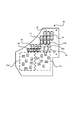
図1乃至図3に示すように、本実施例のパチンコ遊技機1は、遊技機枠50と、遊技機枠50内に取り付けられた遊技盤2とを備えており、遊技盤2は遊技機枠50から着脱自在に構成されている。図3は、遊技盤2を遊技機枠50から取り外した状態のものを示す。遊技機枠50は、装飾面を有する前面枠51と、遊技盤2等を取り付ける本体枠52と、パチンコ遊技機1をホールの島設備に取り付けるための外枠53と、を有して構成されており、前面枠51、本体枠52及び外枠53は、一側端側で軸支され夫々開閉可能に構成されている。
As shown in FIGS. 1 to 3, the
また、前面枠51には、遊技者の操作量(回転角度)に応じた発射強度で遊技球を発射させるための発射ハンドル60、遊技球を貯留し貯留した遊技球を発射装置側に供給可能な打球供給皿(上皿)61、及び打球供給皿61に収容しきれない遊技球を貯留する余剰球受皿(下皿)62が設けられている。さらに、前面枠51には、遊技の進行に伴って実行される遊技演出の実行中などに遊技者が操作可能な第1演出ボタン63a、第2演出ボタン63b(これら2個の演出ボタンを総称して単に「演出ボタン63」ともいう)や、遊技の状況に応じて様々な光を発することが可能な装飾用の枠ランプ66、遊技の状況に応じて様々な音(効果音)を発することが可能な左右一対のスピーカ67等も設けられている。
Further, the
また、前面枠51の上部であって左右のスピーカ67の間には、枠可動装飾部材13が手前側に突出して設けられている。枠可動装飾部材13は、上面が開閉可能な箱型の収容部に演出可動体を収容してなるもので、例えば、比較的大当りの可能性の高い遊技演出の実行に伴って動作することで、演出可動体が収容部の上面から突出するように構成されている。この枠可動装飾部材13の動作により、遊技者は当りへの期待感を高めることとなる。
Further, a frame movable
さらに、前面枠51における打球供給皿61の上方には、当該前面枠51を閉めた状態で遊技盤2の表面(遊技盤面)を外部から視認可能とする視認窓51aが設けられている。この視認窓51aは透明のガラス板によって構成されており、遊技者は、この視認窓51a(ガラス板)を通して、遊技盤2の表面に形成される後述の遊技領域3や、遊技盤2の裏側に配置される画像表示装置71,72の表示内容等を見ることができる。
Further, above the hit
演出ボタン63は、遊技者による入力が可能な入力手段として機能するもので、遊技演出の種類に応じて使用する演出ボタンを使い分けることができる。例えば、遊技演出の実行中に第1演出ボタン63aまたは第2演出ボタン63bを操作すると、当該操作に基づいて所定の操作対応演出が行われる。尚、演出ボタン63の構成は本実施例の態様に限らず、遊技者が入力を行うことができるものであれば足り、例えば、遊技者が直接ボタン部に接触して入力を行う入力手段(例えば、出没式、タッチセンサ式等)であってもよいし、遊技者の身体の一部が近接したことを検知して入力を行う非接触式の入力手段(光電式等)であってもよい。また、演出ボタンが、上方や手前側に突出したり振動したりする等の演出動作を行うもの(可動式の演出操作手段)であってもよい。
The effect button 63 functions as an input means that can be input by the player, and the effect button to be used can be used properly according to the type of the game effect. For example, when the
遊技盤2は、アクリルやポリカーボネート等の透明の合成樹脂からなる透明板を主体として構成されている。本実施例では、樹脂製の矩形のベース部材に透明板を組み付けたものとしている。図3に示すように、遊技盤2(透明板)の表面(盤面)には、発射ハンドル60の操作により発射された遊技球を案内する略円弧状の案内片4が設けられている。この案内片4は、遊技盤2の表面に突出して設けられるリブ状の突出片や金属製のレール部材等からなるもので、主として、外周側に設けられる外案内片4a(外レール)と、外案内片4aより内側に遊技球の通過を許容する間隔を空けて設けられる内案内片4b(内レール)とにより構成される。尚、遊技盤2のことを「透明遊技盤」ともいう。
The
遊技盤2の盤面のうち、案内片4(外案内片4a)より内側の領域は、遊技球が流下可能な遊技領域3となっている。遊技領域3には、遊技球の動きに変化を与えつつ遊技球を所定方向に誘導する遊技釘(図示せず)や、当該領域内を移動(流下)する遊技球が通過したり入球したりすることが可能なゲート、入球口等が設けられる。尚、ゲートおよび入球口等については後述する。そして、遊技領域3のうち、盤面略中央より左側の領域を左遊技領域3Lとしており、盤面略中央より右側の領域を右遊技領域3Rとしている。また、左遊技領域3L側に位置する内案内片4bの先端(上端)には球戻り防止片6が設けられており、発射ハンドル60の操作により発射された遊技球が球戻り防止片6を越えることで、遊技球は遊技領域3(左遊技領域3L)に進入することが可能となる。尚、球戻り防止片6は、一旦遊技領域3へ誘導された(遊技領域3に進入した)遊技球が発射装置側へ戻るのを防止するものである。
Of the board surface of the
遊技盤2の盤面略中央には開口部2Hが設けられており、当該開口部2Hの開口縁にはセンター装飾体10が装着されている。センター装飾体10(開口部2H)は、遊技盤2の裏側に設けられた下画像表示装置71の表示画面71a(表示領域)の大半と、同じく遊技盤2の裏側に設けられた上画像表示装置72の表示画面72a(表示領域)の一部(画面中央から下方)を、略円弧状に囲む形状となっている。このセンター装飾体10の内側(つまり、開口2H)を通して、下画像表示装置71(表示画面71a)および上画像表示装置72(表示画面72a)の表示内容が視認可能となる。尚、前述したように、遊技盤2は透明遊技盤として構成されていることから、特に、上画像表示装置72(表示画面72a)の表示内容は、センター装飾体10の内側(開口部2Hの上側部分)だけでなく、その周囲の遊技領域3を通しても視認すること(透視)が可能となる。
An
また、本実施例では、下画像表示装置71の上方に上画像表示装置72を並べて配置しているが、上画像表示装置72の表示画面72aの上方部分(上方約1/3の部分)は、遊技盤2を構成する透明の遊技板の上端からはみ出た状態となっている。具体的には、図47に示すように、下画像表示装置71の前面側上部(表示画面71aの上部)に上画像表示装置72の下端が位置するとともに、上画像表示装置72の上端が遊技機前方(手前側)へ傾いて、表示画面72aの上方部分が遊技盤2(透明板)の上端(上辺)より上方に突出する配置構成で、画像表示装置71,72を遊技盤2の裏面側に組み付けてある。画像表示装置71,72の組み付け(装着)は、例えば、図示しない表示装置保持部材(ベース部材)に画像表示装置71,72を保持させた状態で、当該保持部材を遊技盤2の裏面にねじ止め等により固定することによってなされる。これにより、画像表示装置71,72と遊技盤2とを一体化できる。但し、画像表示装置71,72の組み付け態様は、これに限られるものではなく、例えば、遊技盤2を保持する本体枠52側に画像表示装置71,72の一方または両方を組み付ける等、種々の態様を採ることが可能である。尚、下画像表示装置71の表示画面71aと上画像表示装置72の表示画面72aとのなす角は、遊技機前方に着席している遊技者の視野(視認性)や画像表示装置の配置スペース等を考慮して、135度〜175度の範囲内とするのが好ましい。
Further, in this embodiment, the upper
そして、遊技盤2の表面側の上部には、外案内片4aより外側(上方)の部位を、上画像表示装置72(表示画面72a)のはみ出た部分(はみ出し部)を含めて覆う透明のカバー2Kが装着されている(図3、図47を参照)。したがって、上画像表示装置72(表示画面72a)の表示内容は、センター装飾体10の内側(つまり、開口2H)やその周囲の遊技領域3、さらには遊技領域3の外側(外案内片4aより外側)を覆うカバー2Kを通して、視認することが可能となっている。
Then, on the upper portion of the
下画像表示装置71および上画像表示装置72は、それぞれ液晶表示器からなるものである。両表示装置の表示画面サイズ(表示領域の大きさ)は、下画像表示装置71の方が上画像表示装置72よりも大きい(換言すると、上画像表示装置72の方が下画像表示装置71よりも小さい)ものなっている。これら2つの画像表示装置の表示画面では、遊技の状況に応じて様々な演出が繰り広げられる。当該演出の代表的なものとして、後述する第1特別図柄や第2特別図柄の変動表示に同期して3つの演出図柄8L,8C,8R(単に「演出図柄8」ともいう)の変動表示を行う演出図柄遊技演出(変動演出)がある。図3に示す表示画面の表示内容は、変動演出が行われる場合の概略を示している。
The lower
本実施例における演出図柄8の変動表示は、下画像表示装置71の表示画面71aと上画像表示装置72の表示画面72aを用いて行われるものとなっており、両表示画面71a,72aに跨って演出図柄表示領域(「演出表示部」ともいう)が設けられている。また、両表示画面71a,72aには、画面背景(変動演出の背景)を構成する背景画像が表示される背景表示領域も設けられている。この背景表示領域も「演出表示部」として捉えることが可能である。
The variable display of the
尚、下画像表示装置71のことを「第1表示手段」や「第1画像表示手段」ともいい、上画像表示装置72のことを「第2表示手段」や「第2画像表示手段」ともいう。また、下画像表示装置71および上画像表示装置72を総じて「画像表示装置」ともいい、画像表示装置のことを「表示手段」や「画像表示手段」ともいう。さらに、表示画面71aのことを「第1表示画面」ともいい、表示画面72aのことを「第2表示画面」ともいい、表示画面71a,72aを総じて「表示画面」ともいう。
The lower
本実施例では、演出図柄8の変動表示を、図48(a)に示すように、表示画面72aの上部から表示画面71aの下部に向かって(上下方向に)演出図柄8をスクロール表示するものとしている。この演出図柄8の変動表示が終了すると、図3や図48(b)に示すように、表示画面71aに演出図柄8が停止表示される。演出図柄遊技演出(変動演出)は、原則、図48や図49に示すように、下画像表示装置71の表示画面71aと上画像表示装置72の表示画面72aの両方を用いて行われる。但し、変動演出の態様(変動演出パターン)によっては、表示画面71aで行われる演出表示の補助的な演出表示(例えば実行中のリーチ演出や演出モードの種類を示す文字やキャラクタ等の表示)を表示画面72bで行う場合もある。つまり、表示画面サイズの大きい下画像表示装置71を主表示装置として用い、表示画面サイズの小さい上画像表示装置72を副表示装置として用いる場合もある。
In this embodiment, as shown in FIG. 48A, the variable display of the
尚、演出図柄8の変動表示の態様には、上下方向の他にも、例えば、左右方向や斜め方向等にスクロール表示する態様がある。演出図柄表示領域7bは、例えば「左」「中」「右」の3つの図柄表示エリアからなり、左の図柄表示エリアには左演出図柄8Lが表示され、中の図柄表示エリアには中演出図柄8Cが表示され、右の図柄表示エリアには右演出図柄8Rが表示される。尚、左・中・右の図柄表示エリアの位置は夫々区別して設ける必要はなく、左・中・右の演出図柄の表示エリアをそれぞれ図柄表示エリア(演出図柄表示領域7b)の全体としてもよい。
In addition to the vertical direction, there is a mode in which the
本実施例の演出図柄8L,8C,8Rは、それぞれ「1」〜「9」までの数字を表した複数の図柄(識別情報)からなる。演出図柄表示領域7bに停止表示される左、中、右の演出図柄の組み合わせ(停止表示態様)によって、後述の第1特別図柄表示器41a(「第1特別図柄表示部」ともいう)に表示される第1特別図柄の変動表示の表示結果や、第2特別図柄表示器41b(「第2特別図柄表示部」ともいう)に表示される第2特別図柄の変動表示の表示結果、つまり、特別図柄当否判定(単に「当否判定」ともいう)の結果を、遊技者が認識し易いように表示する。本実施例では、変動表示している演出図柄8L,8C,8Rの停止順序を、原則、「左→右→中」としている。尚、第1特別図柄および第2特別図柄のいずれかを指して単に「図柄」や「識別情報」ということがある。また、普通図柄を「普図」、特別図柄を「特図」、第1特別図柄を「特図1」「第1特図」、第2特別図柄を「特図2」「第2特図」ということがある。
The
例えば、特別図柄当否判定の結果が大当りとなった場合には、「777」などの3桁同一のゾロ目(「当り演出図柄」ともいう)で演出図柄を停止表示することが可能である。また、小当りとなった場合には「135」などの予め設定したチャンス図柄や「3★3」などの専用図柄(「小当り演出図柄」ともいう)で演出図柄を停止表示することが可能である。また、外れとなった場合には「637」や「373」などの3つの図柄のうち少なくとも1つの図柄が異なるバラケ目図柄(「外れ演出図柄」ともいう)で演出図柄を停止表示することが可能である。これにより、遊技者は停止表示した演出図柄を見ることで、遊技の進行状況を容易に把握することが可能となる。つまり遊技者は、一般的には特別図柄当否判定の結果を第1特別図柄表示器41aや第2特別図柄表示器41bに表示される特別図柄を見て直接的に把握するのではなく、演出図柄表示領域7bに表示される演出図柄を見て把握する。
For example, when the result of the special symbol hit / fail determination is a big hit, it is possible to stop and display the effect symbol with the same three-digit doublet (also referred to as “hit effect symbol”) such as “777”. In addition, in the case of a small hit, it is possible to stop and display the production symbol with a preset chance symbol such as "135" or a special symbol such as "3 ★ 3" (also referred to as a "small hit production symbol"). Is. In addition, in the case of deviation, at least one of the three symbols such as "637" and "373" may be stopped and displayed with a different pattern (also referred to as "off effect symbol"). It is possible. As a result, the player can easily grasp the progress of the game by looking at the stopped display of the effect symbol. That is, in general, the player does not directly grasp the result of the special symbol winning / failing determination by looking at the special symbol displayed on the first
ここで、演出図柄の停止表示態様のうち、特別図柄当否判定の結果が大当りの場合に対応する停止表示態様(本実施例ではゾロ目)のことを「大当り態様」や「特定態様」、「特定表示結果」等ということがあり、特別図柄当否判定の結果が外れの場合に対応する停止表示態様(本実施例ではバラケ目)のことを「外れ態様」や「非特定態様」、「非特定表示結果」等ということがある。また、特別図柄当否判定の結果が小当りの場合に対応する停止表示態様のことを「小当り態様」や「所定態様」、「所定表示結果」等ということがある。 Here, among the stop display modes of the effect symbols, the stop display mode (doublet in this embodiment) corresponding to the case where the result of the special symbol hit / fail determination is a big hit is referred to as "big hit mode", "specific mode", or ". Sometimes referred to as "specific display result", etc., the stop display mode (doublet in this embodiment) corresponding to the case where the result of the special symbol hit / fail judgment is wrong is referred to as "out of shape", "non-specific mode", or "non-specific display". It may be called "specific display result". In addition, the stop display mode corresponding to the case where the result of the special symbol hit / fail determination is a small hit may be referred to as a "small hit mode", a "predetermined mode", a "predetermined display result", or the like.
下画像表示装置71の表示画面71aの中央下部(下領域)には、後述の第1特図保留の記憶数に応じて第1演出保留9a(「第1特図保留画像」ともいう。)を表示する第1演出保留表示領域9c(第1演出保留表示部)と、後述の第2特図保留の記憶数に応じて第2演出保留9b(「第2特図保留画像」ともいう。)を表示する第2演出保留表示領域9d(第2演出保留表示部)と、が設けられている。第1演出保留や第2演出保留の表示態様(表示数)により、後述の第1特図保留表示器43a(図4を参照)にて表示される第1特図保留の記憶数及び第2特図保留表示器43bにて表示される第2特図保留の記憶数を、遊技者にわかりやすく示すことができる。尚、第1演出保留9aおよび第2演出保留9bを総じて「演出保留」または「特図保留画像」ともいう。
In the lower center (lower area) of the
上画像表示装置72の表示画面72aの左上部(左上表示領域)には、演出図柄8の数字を縮小した3つの小演出図柄8l,8c,8r(単に「小演出図柄8a」ともいう)を表示する小演出図柄表示領域8b(小演出図柄表示部)が設けられている。小演出図柄8aは、演出図柄8の変動表示の開始に伴って変動表示を開始し、演出図柄8の変動表示の終了(停止表示)に伴って変動表示を終了(停止表示)する(図48を参照)。尚、図49に示すように、リーチ演出等の実行により3つの演出図柄8L,8C,8Rのうちの2つが停止して残り1つが変動表示する場合であっても、3つの小演出図柄8l,8c,8rは、すべて変動表示を続けるものとなっている。つまり、小演出図柄8l,8c,8rは特別図柄が変動表示している間、これに同期して変動表示するものとなっている。また、図48や図49に示すように、小演出図柄8の変動表示は、小演出図柄表示領域8bで個々の小演出図柄が左右方向(横方向)に回転表示するものとなっている。さらに、図3や図48(b)に示すように、小演出図柄8aの停止表示態様は、演出図柄8の停止表示態様と同様に3桁の数字のゾロ目やバラケ目となっており、特別図柄当否判定の結果に即したものとなっている。
In the upper left portion (upper left display area) of the
また、上画像表示装置72の表示画面72aの右上部(右上表示領域)には、特別図柄の変動表示回数を示す回数画像77aを表示する変動回数表示領域77(回数表示部)が設けられており、その右側には、第1特別図柄と同期して変動表示および停止表示する特図1第四図柄78aと、第2特別図柄と同期して変動表示および停止表示する特図2第四図柄78bとを表示する第四図柄表示領域78が設けられている。変動回数表示領域77に表示される回数画像77aは、後述の低ベース状態にて大当りが発生するまでに行われる特別図柄の変動表示の実行回数(変動表示回数)を示すものであり、特別図柄の変動表示毎に1ずつ加算表示されるものとなっている。つまり、高ベース状態では変動回数表示領域77に回数画像77a(変動表示回数)が表示されないものとなっている。尚、本実施例の回数画像77aは、変動表示回数を算用数字(アラビア数字)で表すのものとなっており、最大4桁(千の位)まで表示可能となっている。
Further, in the upper right portion (upper right display area) of the
第四図柄表示領域78に表示される特図1第四図柄78aは、第1特別図柄の変動表示および停止表示にあわせて変動表示および停止表示を行うものである。具体的に、特図1第四図柄78aの変動表示を点滅表示の態様で行い、停止表示を点灯表示の態様で行う。この点灯表示(特図1第四図柄78aの停止表示)は、第1特別図柄当否判定の結果(第1特別図柄の変動表示の表示結果)に応じた色(例えば、外れ「青」、小当り「緑」、大当り「赤」など)で行われる。同様に、特図2第四図柄78bは、第2特別図柄の変動表示および停止表示にあわせて変動表示および停止表示を行うものである。具体的に、特図2第四図柄78bの変動表示を点滅表示の態様で行い、停止表示を点灯表示の態様で行う。この点灯表示(特図2第四図柄78aの停止表示)は、第2特別図柄当否判定の結果(第2特別図柄の変動表示の表示結果)に応じた色(例えば、外れ「青」、大当り「赤」など)で行われる。
The special figure 1
このように、第四図柄や小演出図柄8aを表示するのは、演出図柄遊技演出の一環としてリーチ演出や発展演出等を行うにあたり、演出図柄表示領域7b(演出表示部)の略全域に亘ってキャラクタ画像やエフェクト画像等の各種演出画像を表示したり、後述の盤可動装飾部材14が動作して演出図柄表示領域7b(演出表示部)を被覆したりする等して、特別図柄(演出図柄)が変動表示しているか否かを把握し難い状況が発生し得るからである。尚、特図1第四図柄78aおよび特図2第四図柄78bを総じて「第四図柄」ともいう。また、画像表示装置に表示される演出保留(特図保留画像)や第四図柄、小演出図柄8a等、遊技の進行に係る情報を示す画像のことを「情報画像」ともいう。さらに、演出図柄8、小演出図柄8aおよび第四図柄の何れか又は全部を指して、単に「図柄」、「演出図柄」または「識別情報」ということがある。
In this way, displaying the fourth symbol and the
また、画像表示装置71,72の表示画面上では、前述のような演出図柄等を用いた演出図柄遊技演出(変動演出)を表示するほか、当り遊技に伴って実行される当り遊技演出や客待ち用のデモ演出等が表示される。さらに、演出図柄遊技演出や当り遊技演出やデモ演出では、数字等の演出図柄のほか、背景画像やキャラクタ画像などの演出図柄以外の様々な演出画像も表示される。
Further, on the display screens of the
遊技盤2(遊技領域3)の中央付近には、前述したように、表示画面71aの大半と表示画面72aの一部(画面中央より下方の部分)を取り囲むようにして、センター装飾体10が設けられている。センター装飾体10の下部には、遊技球が転動可能な遊技球転動面を有するステージ部11が設けられている。また、センター装飾体10の左部には、中空状のワープ部12が設けられている。ワープ部12にはワープ入口とワープ出口とが設けられており、遊技領域3を流下する遊技球をワープ入口から受け入れ、当該遊技球をワープ出口から排出しステージ部11へと誘導する。ステージ部11の転動面に誘導された遊技球は、ステージ部11に誘導されない遊技球と比して高い可能性で、後述の第1始動口20に入球可能とされている。
In the vicinity of the center of the game board 2 (game area 3), as described above, the
また、センター装飾体10の下部裏側と、左部裏側および右部裏側には、遊技演出に伴って動作可能な3つの盤可動装飾部材14L,14C,14R(単に「盤可動装飾部材14」ともいう)がそれぞれ設けられている。図3では、盤可動装飾部材14は一部分のみが視認可能となっているが、例えば、比較的大当りの可能性の高い遊技演出の実行に伴って、盤可動装飾部材14L,14C,14Rのうちの1つ、2つまたは3つが表示画面71aの手前に出現して前面を覆い、その大部分が視認可能となる。盤可動装飾部材14の動作により、遊技者は当りへの期待感を高めることとなる。
Further, on the lower back side of the center
遊技領域3の中央下方(下画像表示装置71の下方)には、遊技球の入球し易さ(遊技球受入口の大きさ)が変化しない非可変式の第1始動口20を備える固定入賞装置19(「非可変始動口」ともいう)が設けられている。第1始動口20への遊技球の入球に基づいて、特別図柄当否判定用乱数等が取得され、予め定められた所定条件が成立すると第1特別図柄に係る当否判定(第1特別図柄当否判定)が実行されると共に第1特別図柄が変動表示され、当否判定の結果に基づいて停止表示される。
A non-variable first starting
第1始動口20の下方には、遊技球の入球し易さ(遊技球受入口の大きさ)が変化する可変式の第2始動口21を備える可変入賞装置22(「可変始動口」ともいう)が設けられている。第2始動口21への遊技球の入球に基づいて、特別図柄当否判定用乱数等が取得され、予め定められた所定条件が成立すると第2特別図柄の当否判定(第2特別図柄当否判定)が実行されると共に第2特別図柄が変動表示され、当否判定の結果に基づいて停止表示される。
Below the
可変入賞装置22は、可動部材23を備え、可動部材23の動作によって第2始動口21を開閉するものである。この開閉動作によって、第2始動口21は、第1の態様(閉状態)から当該第1の態様よりも遊技球の入球可能性が高い第2の態様(開状態)へと変化可能である。つまり、可動部材23は、所定の動作(開閉動作)を行うことで、第2始動口21への遊技球の入球可能性を変化させるものである。この可動部材23は、第2始動口ソレノイド24(図5を参照)により駆動される。本実施例では、第2始動口21は、可動部材23が開状態にあるときだけ遊技球が入球可能とされ、可動部材23が閉状態にあるときには遊技球が入球不能となっている。尚、第2始動口21は、可動部材23が閉状態にあるときは開状態にあるときよりも遊技球が入球困難となるものであれば、可動部材23が閉状態にあるときに完全に入球不能となるものでなくてもよい。
The
遊技領域3における第1始動口20の右方(右遊技領域3R)には、第1大入賞口30(「第1可変入球口」ともいう)を備えた第1大入賞装置31が設けられている。第1大入賞装置31は、開閉部材32を備え、開閉部材32の作動により第1大入賞口30を開閉するものである。開閉部材32は、第1大入賞口ソレノイド33(図5を参照)により駆動される。第1大入賞口30は、開閉部材32が開状態にあるときだけ遊技球が入球可能となる。すなわち、第1大入賞装置31は、開閉部材32の開閉動作により、遊技球が入球不能な入球不能状態(閉状態)と遊技球が入球可能な入球可能状態(開状態)とに変化可能である。
On the right side of the first starting port 20 (
また、遊技領域3における第1大入賞口30の右上(右遊技領域3R)には、第2大入賞口35(「第2可変入球口」ともいう)を備えた第2大入賞装置36が設けられている。第2大入賞装置36は、左右方向(水平方向)に回動可能な開閉部材(羽根部材)37を備えており、開閉部材37の作動により第2大入賞口35を開閉するものである。開閉部材37は、第2大入賞口ソレノイド38(図5を参照)により駆動される。第2大入賞口35は、開閉部材37が開状態にあるときだけ遊技球が入球可能となる。すなわち、第2大入賞装置36は、開閉部材37の開閉動作により、遊技球が入球不能な入球不能状態(閉状態)と遊技球が入球可能な入球可能状態(開状態)とに変化可能である。
Further, in the upper right corner (
第2大入賞装置36には、第2大入賞口35に入球した遊技球が通過可能な特定領域39が形成されている。本パチンコ遊技機1では、第2大入賞口35に入球した遊技球の少なくとも1個が特定領域39を通過したことが検知されることに基づいて、後述の高確率状態を発生させている。つまり特定領域39は、確変作動口となっている。このような特定領域39は、第1大入賞装置31には設けられていない。このような確変作動口としての特定領域39(V領域)を備える第2大入賞口35(第2大入賞装置36)のことを「Vアタッカー」ともいう。尚、高確率状態は、特別遊技とは別に遊技者に付与される遊技上の特典の一つである。
The second special winning
また、遊技領域3における第1大入賞口30の真上(右遊技領域3R)には、遊技球が通過可能なゲート28(遊技球通過口)が設けられている。ゲート28への遊技球の通過に基づいて、普通図柄当否判定用乱数等が取得され、予め定められた所定条件が成立すると、第2始動口21を開状態とするか否かを判定する普通図柄当否判定が実行されると共に普通図柄が変動表示され、普通図柄当否判定の結果に基づいて停止表示される。当り普通図柄が停止表示すると第2始動口21を開状態となる。さらに、遊技領域3の下部には、複数の一般入賞口27が設けられている。本実施例では、一般入賞口27を4個設けてあり、そのうちの3個を第1始動口20の左方(左遊技領域3L)に設けられた左一般入賞口とし、1個を第1大入賞口30の右方(右遊技領域3R)に設けられた右一般入賞口としている。第1始動口20、第2始動口21、第1大入賞口30、第2大入賞口35、及び一般入賞口27は、それぞれ賞球の払い出し契機となる入球口であり、各入球口に遊技球が入球した場合には、夫々の入球口において予め定められた数の遊技球(賞球)が払い出される。具体的には、第1始動口20の賞球数は「4」、第2始動口21の賞球数は「2」、第1大入賞口20および第2大入賞口35の賞球数は「15」、一般入賞口27の賞球数は「10」としている。
Further, a gate 28 (game ball passage port) through which a game ball can pass is provided directly above the first large winning opening 30 (
このように複数の入球口(第1始動口20、第2始動口21、第1大入賞口30、第2大入賞口35、一般入賞口27及びゲート28)等が配されている遊技領域3を、左右方向の中央より左側の左遊技領域3L(第1領域)と、右側の右遊技領域3R(第2領域)と、に分けることができる。左遊技領域3Lを遊技球が流下するように遊技球を発射することを「左打ち」といい、右遊技領域3Rを遊技球が流下するように遊技球を発射することを「右打ち」という。ここで、複数の入球口のうち、第1始動口20および3個の左一般入賞口27は、遊技領域3のうち左遊技領域3Lを流下する遊技球が入球可能となるように設けてあり、第2始動口21、第1大入賞口30、第2大入賞口35、右一般入賞口27およびゲート28は、遊技領域3のうち右遊技領域3Rを流下する遊技球が入球可能となるように設けてある。本パチンコ遊技機1では、遊技開始の際には、原則、左打ちにて第1始動口20への入球を狙う。一方、第1始動口20への入球に基づく当否判定において当りとなり遊技状態が変化した際には、原則、右打ちにてゲート28、第2始動口21、第1大入賞口30および第2大入賞口35への入球を狙うこととなる。
In this way, a game in which a plurality of entry ports (first start opening 20, second start opening 21, first large winning
また、図3および図4に示すように、遊技盤2の右下部には主表示器40が配置されている。主表示器40には、第1特別図柄を変動表示および停止表示する第1特別図柄表示器41a(第1特別図柄表示部)と、第2特別図柄を変動表示および停止表示する第2特別図柄表示器41b(第2特別図柄表示部)と、普通図柄を変動表示および停止表示する普通図柄表示器42(普通図柄表示部)と、が含まれている。また主表示器40には、第1特別図柄に係る当否判定情報(第1特図保留)の記憶数を表示する第1特図保留表示器43aと、第2特別図柄に係る当否判定情報(第2特図保留)の記憶数を表示する第2特図保留表示器43bと、普通図柄表示器42の作動保留(普図保留)の記憶数を表示する普図保留表示器44と、が含まれている。さらに主表示器40には、第1特別図柄当否判定または第2特別図柄当否判定の結果が当りになったことを示す当り表示器48と、第1特別図柄当否判定または第2特別図柄当否判定の結果が当りになった場合に実行される当り遊技のラウンド数を示すラウンド表示器45と、確率変動機能が作動することを示す遊技状態表示器46と、遊技球の発射方向、すなわち右打ちを行うべき状態か左打ちを行うべき状態かを示す発射方向表示器47と、が含まれている。主表示器40に含まれるこれらの各種表示器は後述の主制御部によって表示制御される。
Further, as shown in FIGS. 3 and 4, a
第1特別図柄の変動表示は、第1始動口20への遊技球の入球に基づいて行われる。第2特別図柄の変動表示は、第2始動口21への遊技球の入球に基づいて行われる。尚、以下の説明では、第1特別図柄および第2特別図柄を総称して「特別図柄」ということがある。また、第1特別図柄表示器41aおよび第2特別図柄表示器41bを総称して「特別図柄表示部41」ということがある。また、第1特図保留表示器43aおよび第2特図保留表示器43bを総称して「特図保留表示部43」ということがある。
The variation display of the first special symbol is performed based on the entry of the game ball into the
特別図柄表示部41では、特別図柄(識別情報)を所定時間変動表示した後に停止表示し、停止表示された特別図柄(停止図柄)によって第1始動口20または第2始動口21への入球に基づく抽選(特別図柄当否判定、大当り抽選)の結果を報知する。停止表示される特別図柄は、特別図柄当否判定によって複数種類の特別図柄の中から選択された一つの特別図柄である。停止図柄が予め定めた特定特別図柄(特定識別情報)である場合、すなわち、特別図柄の停止表示の態様(特別図柄の変動表示の表示結果)が大当り図柄や小当り図柄等の当り態様である場合には、停止表示された当り図柄の種類に応じた開放パターンにて第1大入賞口30または第2大入賞口35を開放させる特別遊技(大当り遊技、小当り遊技)が行われる。尚、特別遊技における大入賞口(第1大入賞口30及び第2大入賞口35)の開放パターンについては後述する。
In the special symbol display unit 41, the special symbol (identification information) is displayed in a variable manner for a predetermined time, then stopped and displayed, and the ball enters the
図4に示すとおり、第1特別図柄表示器41aは、「i〜p」で示す8個のLEDで構成されており、第1特別図柄当否判定の結果に応じた特別図柄を表示する。本実施例では、第1特別図柄当否判定の結果として「15R第1大当り」、「15R第2大当り」、「5R第3大当り」および「2R第4大当り」の4種類の大当りと、第1小当りが設けられており(図6、図8を参照)、第1特別図柄表示器41aのLEDは、それら大当り及び小当りの各々に応じた表示態様を採ることが可能となっている。例えば、第1特別図柄当否判定の結果が第1大当り(15R大当り)となった場合には、「ijn」の3個のLEDを点灯して残りを消灯する(15R第1大当り図柄)。また、第2大当り(15R大当り)となった場合には、「ijk」の3個のLEDを点灯し残りを消灯する(15R第2大当り図柄)。また、第3大当り(15R大当り)となった場合には、「ijl」の3個のLEDを点灯し残りを消灯する(15R第3大当り図柄)。また、第4大当り(2R大当り)となった場合には、「jnop」の4個のLEDを点灯し残りを消灯する(2R第4大当り図柄)。また、第1小当りとなった場合には、「mnop」の4個のLEDを点灯し残りを消灯する(小当り図柄)。また、外れとなった場合には、「lo」の2個のLEDを点灯し残りを消灯する(外れ図柄)。
As shown in FIG. 4, the first
一方、第2特別図柄表示器41bは、「a〜h」で示す8個のLEDで構成されており、第2特別図柄当否判定の結果に応じた特別図柄を表示する。本実施例では、第2特別図柄当否判定の結果として「15R第5大当り」と「15R第6大当り」の2種類の大当りとが設けられており(図8を参照)、第2特別図柄表示器41bのLEDは、それら大当りの各々に応じた表示態様を採ることが可能となっている。例えば、第2特別図柄当否判定の結果が、第5大当り(15R大当り)となった場合には、「abd」の3個のLEDを点灯し残りを消灯する(15R第5大当り図柄)。また、第6大当り(15R大当り)となった場合には、「abc」の3個のLEDを点灯し残りを消灯する(15R第6大当り図柄)。また、第2小当りとなった場合には、「cdeh」の4個のLEDを点灯し残りを消灯する(第2小当り図柄)。また、外れとなった場合には、「eh」の2個のLEDを点灯し残りを消灯する(外れ図柄)。
On the other hand, the second
尚、特別図柄の停止表示態様(停止図柄)は、これらに限定されるものではなく、任意に設定することができる。また、特別図柄が停止表示される前には所定の変動時間にわたって特別図柄の変動表示がなされるが、その変動表示の態様は、例えば、予め定められた順序で光が左から右へ繰り返し流れるように各LEDを点灯させる態様とすることができる。 The stop display mode (stop symbol) of the special symbol is not limited to these, and can be set arbitrarily. Further, before the special symbol is stopped and displayed, the fluctuation display of the special symbol is performed over a predetermined fluctuation time, and the mode of the fluctuation display is, for example, the light repeatedly flows from left to right in a predetermined order. Each LED can be turned on as described above.
本パチンコ遊技機1では、第1始動口20または第2始動口21への遊技球の入球があると、その入球に基づいて特別図柄当否判定用乱数等の各種情報(「取得情報」ともいう)を取得し、取得した各種情報は、主制御部のRAMに形成される特図保留記憶部(図示せず)に一旦記憶される。詳細には、第1始動口20への入球であれば第1特図保留(第1取得情報)として第1特図保留記憶部(図示せず)に記憶され、第2始動口21への入球であれば第2特図保留(第2取得情報)として第2特図保留記憶部(図示せず)に記憶される。各々の特図保留記憶部に記憶可能な特図保留(取得情報)の数は所定数までとされており、本実施例におけるその上限値はそれぞれ「4」となっている。これら第1特図保留記憶部および第2特図保留記憶部を、夫々「第1取得情報記憶手段」および「第2取得情報記憶手段」ともいい、総じて「取得情報記憶手段」ともいう。
In the
特図保留記憶部に記憶された特図保留は、その特図保留に基づく特別図柄の変動表示が可能となったときに消化される。特図保留の消化とは、その特図保留に対応する特別図柄当否判定用乱数等を判定して、その判定結果を示すための特別図柄の変動表示を実行することをいう。従って、本パチンコ遊技機1では、第1始動口20または第2始動口21への遊技球の入球に基づく特別図柄の変動表示がその入球時にすぐに実行できない場合、すなわち特別図柄の変動表示の実行中や特別遊技の実行中である場合であっても、所定数を上限として、その入球に対する特別図柄当否判定の権利を留保することが可能となっている。
The special figure hold stored in the special figure hold storage unit is digested when the variable display of the special symbol based on the special figure hold becomes possible. The digestion of the special symbol hold means to determine the random number for determining whether the special symbol is correct or not corresponding to the special symbol hold, and to execute the variable display of the special symbol to show the determination result. Therefore, in the
特図保留記憶部に記憶された特図保留の数は、第1特図保留表示器43aおよび第2特図保留表示器43bに表示される。具体的には、第1特図保留表示器43aは「uv」の2個のLEDで構成されており、第1特図保留の数に応じてLEDを表示制御することにより、第1特図保留の数を表示するものとなっている。例えば、保留数が「0」の場合は「u□v□」(例えば、□:消灯、●:赤点灯、▲:緑点灯とする)というように両LEDを消灯する表示態様とし、保留数が「1」の場合は「u□v●」というように「u」のLEDを消灯し「v」のLEDを赤色で点灯させる表示態様とし、保留数が「2」の場合は「u●v□」というように「u」のLEDを赤色で点灯させ「v」のLEDを消灯する表示態様とし、保留数が「3」の場合は「u●v●」というように両方のLEDを赤色で点灯させる表示態様とし、保留数が「4(上限数)」の場合は「u▲v▲」というように両方のLEDを緑色で点灯させ表示態様とすることができる。
The number of special figure hold stored in the special figure hold storage unit is displayed on the first special
また、第2特図保留表示器43bは「wx」の2個のLEDで構成されており、第2特図保留の数に応じてLEDを表示制御することにより、第2特図保留の数を表示するものである。例えば、保留数が「0」の場合は「w□x□」(例えば、□:消灯、●:赤点灯、▲:緑点灯とする)というように両LEDを消灯する表示態様とし、保留数「1」〜「4」についても第1特図保留表示器43aと同様に定められている。
Further, the second special
普通図柄の変動表示は、ゲート28への遊技球の通過を契機として行われる。普通図柄表示器42では、普通図柄を所定時間変動表示した後、停止表示し、停止表示された普通図柄(停止図柄)によって、ゲート28への遊技球の通過に基づく普通図柄当否判定の結果を報知する。停止表示される普通図柄は、普通図柄当否判定によって複数種類の普通図柄の中から選択された一つの普通図柄である。停止表示された普通図柄が予め定めた特定普通図柄(当り普通図柄)である場合には、現在の遊技状態に応じた開放パターンにて第2始動口21を開放させる補助遊技が行われる。尚、第2始動口21の開放パターンについては後述する。
The variable display of the normal symbol is performed when the game ball passes through the
具体的には図4に示す通り、普通図柄表示器42は、「st」の2個のLEDから構成されており、その点灯態様によって普通図柄当否判定の結果に応じた普通図柄を表示するものである。例えば、判定結果が当りである場合には、「s■t■」(例えば、■:点灯、□:消灯とする)というように両LEDが点灯した当り普通図柄を停止表示する。また判定結果が外れである場合には、「s□t■」というように「t」のLEDのみが点灯した態様の外れ普通図柄を表示する。尚、外れ普通図柄は、特定普通図柄ではない。普通図柄が停止表示される前には予め定められた所定の変動時間にわたって普通図柄の変動表示が実行されるが、その変動表示の態様は、例えば両LEDが交互に点灯・消滅を繰り返す態様である。
Specifically, as shown in FIG. 4, the
本パチンコ遊技機1では、ゲート28への遊技球の通過があると、その通過に基づいて普通図柄当否判定用乱数等の各種情報(「取得情報」ともいう)を取得し、取得した各種情報は主制御部のRAMに形成される普図保留記憶部(図示せず)に普図保留として一旦記憶される。普図保留記憶部に記憶可能な普図保留の数は所定数までとされており、本実施例におけるその上限値は「4」となっている。普図保留記憶部に記憶された普図保留は、その普図保留に基づく普通図柄の変動表示が可能となったときに消化される。普図保留の消化とは、その普図保留に対応する普通図柄当否判定用乱数を判定して、その判定結果を示すための普通図柄の変動表示を実行することをいう。従って本パチンコ遊技機1では、ゲート28への遊技球の通過に基づく普通図柄の変動表示がその通過時にすぐ実行できない場合、すなわち普通図柄の変動表示の実行中や補助遊技の実行中である場合であっても、所定個数を上限として、その通過に対する普通図柄当否判定の権利を留保することができるようになっている。
In the
普図保留記憶部に記憶された普図保留の数は、普図保留表示器44に表示される。具体的には普図保留表示器44は、「qr」の2個のLEDで構成されており、普図保留の数に応じてLEDを点灯させることにより普図保留の数を表示するものである。例えば、保留数が「0」の場合は「q□r□」(例えば、□:消灯、●:赤点灯、▲:緑点灯とする)というように両LEDを消灯する表示態様とし、保留数が「1」の場合は「q□r●」というように「q」のLEDを消灯し「r」のLEDを赤色で点灯させる表示態様とすることができる。また、保留数「2」〜「4」についても第1特図保留表示器43aと同様に定められている。
The number of the normal figure hold stored in the normal figure hold storage unit is displayed on the normal
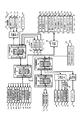
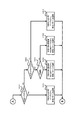
次に図2及び図5に基づいて、本パチンコ遊技機1における電気的な構成を説明する。本実施例のパチンコ遊技機1は、特別図柄当否判定や普通図柄当否判定や遊技状態の移行など、遊技進行や遊技利益に関する制御を行う主制御基板80(「主制御部」ともいい「遊技制御部」ともいう)、遊技の進行に伴って実行する演出に関する制御を行うサブ制御基板90(「サブ制御部」ともいい「演出制御部」ともいう)、遊技球の払い出しに関する制御を行う払出制御基板110(「払出制御部」ともいう)、画像表示装置71,72の表示制御を行う画像制御基板100(画像制御部)等を備えている。
Next, the electrical configuration of the
また、図2に示すように、パチンコ遊技機1の後面側(裏面側)の略中央部には主制御基板80を収納した主制御基板収納ケースが設けられ、この主制御基板ケースの上方には、音声制御基板106、ランプ制御基板107及び画像制御基板100を収納した画像制御基板等収納ケースが設けられ、その画像制御基板等収納ケース上にはサブ制御基板90を収納したサブ制御基板収納ケースが設けられている。また、主制御基板ケースの下方左側には、払出制御基板を収納する払出制御基板ケースが設けられ、その右側には、電源基板109を収納する電源基板ケースが設けられている。
Further, as shown in FIG. 2, a main control board storage case for storing the
主制御基板80には、プログラムに従ってパチンコ遊技機1の遊技の進行を制御する遊技制御用ワンチップマイコン(以下「遊技制御用マイコン」)81が実装されている。遊技制御用マイコン81には、遊技の進行を制御するためのプログラム等を記憶したROM、ワークメモリとして使用されるRAM、ROMに記憶されたプログラムを実行するCPUが含まれている。遊技制御用マイコン81は、入出力回路87(I/Oポート部)を介して他の基板等とデータ(情報)の送受信を行う。入出力回路87は、遊技制御用マイコン81に内蔵されていてもよい。また、ROMは外付けであってもよい。遊技制御用マイコン81のRAMには、前述した特図保留記憶部(第1特図保留記憶部及び第2特図保留記憶部)と普図保留記憶部とが設けられている。また、主制御基板80(遊技制御用マイコン81)のRAM(主制御RAM)の所定アドレスには、各種フラグや各種計数カウンタに用いるための記憶領域が確保されている。
On the
主制御基板80には、中継基板88を介して各種センサやソレノイドが接続されている。そのため、主制御基板80には各センサから信号が入力され、各ソレノイドには主制御基板80から信号が出力される。具体的にはセンサ類としては、第1始動口センサ20a、第2始動口センサ21a、ゲートセンサ28a、第1大入賞口センサ30a、第2大入賞口センサ35a、特定領域センサ39a、非特定領域センサ49aおよび一般入賞口センサ27aが接続されている。これら各種センサを「遊技球検知手段」ともいう。
Various sensors and solenoids are connected to the
第1始動口センサ20aは、第1始動口20内に設けられて第1始動口20に入球した遊技球を検知するものである。第2始動口センサ21aは、第2始動口21内に設けられて第2始動口21に入球した遊技球を検知するものである。ゲートセンサ28aは、ゲート28内に設けられてゲート28を通過した遊技球を検知するものである。第1大入賞口センサ30aは、第1大入賞口30内に設けられて第1大入賞口30に入球した遊技球を検知するものである。第2大入賞口センサ35aは、第2大入賞口35内に設けられて第2大入賞口35に入球した遊技球を検知するものである。特定領域センサ39aは、第2大入賞口35内の特定領域39に設けられており、特定領域39を通過した遊技球を検知するものである。非特定領域センサ49aは、第2大入賞口35内の非特定領域(図示せず)に設けられており、第2大入賞口35に入球した遊技球のうち非特定領域を通過した遊技球(つまり、特定領域39を通過しなかった遊技球)を検知するものである。一般入賞口センサ27aは、各一般入賞口27内にそれぞれ設けられて一般入賞口27に入球した遊技球を検知するものである。
The first
またソレノイド類としては、第2始動口ソレノイド24、第1大入賞口ソレノイド33および第2大入賞口ソレノイド38が接続されている。第2始動口ソレノイド24は、可変入賞装置22の可動部材23を駆動するためのものである。第1大入賞口ソレノイド33は、第1大入賞装置31の開閉部材32を駆動するためのものである。第2大入賞口ソレノイド38は、第2大入賞装置36の開閉部材37を駆動するためのものである。
Further, as the solenoids, the second
さらに主制御基板80には、第1特別図柄表示器41a、第2特別図柄表示器41b、普通図柄表示器42、第1特図保留表示器43a、第2特図保留表示器43b、普図保留表示器44、ラウンド表示器45、遊技状態表示器46、発射方向表示器47および当り表示器48が接続されている。すなわち、これらの主表示器40の表示制御は、遊技制御用マイコン81によりなされる。
Further, the
また主制御基板80は、払出制御基板110に各種コマンドを送信するとともに、払い出し監視のために払出制御基板110から信号を受信する。払出制御基板110には、賞球や貸球を払い出す払出装置120、及びカードユニット135(パチンコ遊技機1に隣接して設置され、挿入されたプリペイドカード(遊技価値記憶媒体)等に記憶されている情報に基づいて球貸しを可能にするもの)が接続されているとともに、発射制御基板111(「発射制御部」ともいう)を介して発射装置112が接続されている。発射装置112には、発射ハンドル60(図1を参照)が含まれる。
Further, the
払出制御基板110は、プログラムに従ってパチンコ遊技機1の遊技球の払い出しを制御する払出制御用ワンチップマイコン116(「払出制御用マイコン」ともいう)が実装されている。払出制御用マイコン116には、遊技球の払い出しを制御するためのプログラム等を記憶したROM、ワークメモリとして使用されるRAM、ROMに記憶されたプログラムを実行するCPUが含まれている。払出制御用マイコン116は、入出力回路117を介し、遊技制御用マイコン81からの信号や、パチンコ遊技機1に接続されたカードユニット135からの信号に基づいて、払出装置120の払出モータ121を駆動して賞球の払い出しを行ったり、貸球の払い出しを行ったりする。払い出される遊技球は、その計数のため払出センサ122、123により検知される。遊技者による発射装置112のハンドル60(図1を参照)の操作があった場合には、タッチスイッチ114が発射ハンドル60への遊技者の接触を検知し、発射ボリューム115が発射ハンドル60の回転量を検知する。そして、発射ボリューム115の検知信号の大きさに応じた強さで遊技球が発射されるよう発射モータ113が駆動制御されることとなる。尚、本実施例では、発射モータ113の駆動により発射装置112が連続して発射可能な遊技球の数は1分間で約100個となっている。
The
また、主制御基板80は、サブ制御基板90に対し各種コマンドを送信する。主制御基板80とサブ制御基板90との接続は、主制御基板80からサブ制御基板90への信号の送信のみが可能な単方向通信接続となっている。すなわち、主制御基板80とサブ制御基板90との間には、通信方向規制手段としての図示しない単方向性回路(例えばダイオードを用いた回路)が介在している。
Further, the
また、図5に示すように、サブ制御基板90には、プログラムに従ってパチンコ遊技機1の演出を制御する演出制御用ワンチップマイコン91(「演出制御用マイコン」)が実装されている。演出制御用マイコン91には、遊技の進行に伴って演出を制御するためのプログラム等を記憶したROM、ワークメモリとして使用されるRAM、ROMに記憶されたプログラムを実行するCPUが含まれている。演出制御用マイコン91は、入出力回路95を介して他の基板等とデータの送受信を行う。入出力回路95は、演出制御用マイコン91に内蔵されていてもよい。また、ROMは外付けであってもよい。また、サブ制御基板90(演出制御用マイコン91)のRAM(演出制御RAM)の所定アドレスには、各種フラグや各種計数カウンタに用いるための記憶領域が確保されている。
Further, as shown in FIG. 5, a one-
サブ制御基板90には、画像制御基板100、音声制御基板106、ランプ制御基板107が接続されている。尚、サブ制御基板90(サブ制御部)や画像制御基板100(画像制御部)、音声制御基板106(音声制御部)、ランプ制御基板107(ランプ制御部)は、遊技の状況に応じて表示演出や音演出、ランプ演出(光演出)等の各種演出を、対応する演出用の装置や部材等(演出手段)に実行させる制御を行う演出制御手段(演出実行手段)として機能するものである。
An
サブ制御基板90の演出制御用マイコン91は、主制御基板80から受信したコマンドに基づいて、画像制御基板100の画像制御用ワンチップマイコン101(「画像制御用マイコン」)のCPUに、下画像表示装置71および上画像表示装置72の表示制御を行わせる。画像制御基板100のRAMは、画像データを展開するためのメモリである。画像制御基板100のROMには、画像表示装置71,72に表示される静止画データや動画データ、具体的にはキャラクタ、アイテム、図形、文字、数字および記号等(演出図柄、保留図柄等を含む)や背景画像等の画像データが格納されている。画像制御用マイコン101は、演出制御用マイコン91からの指令に基づいてROMから画像データを読み出す。そして、読み出した画像データに基づいて表示制御を実行する。尚、画像制御基板100の画像制御用ワンチップマイコン101に換えて、または加えてVDP(Video Display Processor)を設けてもよい。
The
また、演出制御用マイコン91は、主制御基板80から受信したコマンドに基づいて、音声制御基板106を介してスピーカ67から音声、楽曲、効果音等を出力する。スピーカ67から出力する音声等の音響データは、サブ制御基板90のROMに格納されている。尚、音声制御基板106にCPUを実装してもよく、その場合、そのCPUに音声制御を実行させてもよい。さらにこの場合、音声制御基板106にROMを実装してもよく、そのROMに音響データを格納してもよい。また、スピーカ67を画像制御基板100に接続し、画像制御用マイコン101に音声制御を実行させてもよい。さらにこの場合、画像制御基板100のROMに音響データを格納してもよい。
Further, the
さらに、演出制御用マイコン91は、主制御基板80から受信したコマンドに基づいて、枠ランプ66や盤面ランプ5等のランプの発光態様を決める発光パターンデータ(点灯/消灯や発光色等を決めるデータ、ランプデータともいう)を、ROMに格納されているデータから決定し、ランプ制御基板107を介して枠ランプ66や盤面ランプ5等のランプ(LED)の点灯制御を行う。
Further, the
また、演出制御用マイコン91は、主制御基板80から受信したコマンドに基づいて、ランプ制御基板107に中継基板108を介して接続された枠可動装飾部材13や盤可動装飾部材14を動作させる。前述したように、枠可動装飾部材13は前面枠51に設けられ、盤可動装飾部材14はセンター装飾体10に設けられた、可動式のいわゆるギミックのことである。尚、枠可動装飾部材13および盤可動装飾部材14を総じて単に「可動装飾部材」ともいう。
Further, the
演出制御用マイコン91は、可動装飾部材(枠可動装飾部材13、盤可動装飾部材14)を所定の動作態様で動作させるための動作パターンデータ(「駆動データ」ともいう)を、サブ制御基板90のROMに格納されているデータから決定し、決定した動作パターンデータに基づいて可動装飾部材の動作を制御する。尚、ランプ制御基板107にCPUを実装してもよく、この場合、そのCPUにランプの点灯制御や可動装飾部材の動作制御を実行させてもよい。さらにこの場合、ランプ制御基板107にROMを実装してもよく、そのROMに発光パターンや動作パターンに関するデータを格納してもよい。
The
また、サブ制御基板90には、第1演出ボタン63aまたは第2演出ボタン63b(図1参照)が操作(押す、回転、引く等)されたことを検知する第1演出ボタン検知スイッチ63cおよび第2演出ボタン検知スイッチ63dが接続されている。従って、第1演出ボタン63aまたは第2演出ボタン63bに対して遊技者が所定の入力操作を行うと、対応する演出ボタン検知スイッチからサブ制御基板90に対して信号が出力される。尚、第1演出ボタン検知スイッチ63cおよび第2演出ボタン検知スイッチ63dを総称して単に「演出ボタン検知スイッチ」ともいう。
Further, the
次に、本実施例のパチンコ遊技機1における当否判定に係る制御(判定手段)について説明する。特別図柄当否判定の結果として、「大当り」、「小当り」、「外れ」がある。特別図柄当否判定の結果が「大当り」のときには、特別図柄表示部41に「大当り図柄」が停止表示され、「小当り」のときには、特別図柄表示部41に「小当り図柄」が停止表示され、「外れ」のときには、特別図柄表示部41に「外れ図柄」が停止表示される。大当り又は小当りと判定されると、停止表示された特別図柄の種類に応じた開放パターンにて、第1大入賞口30又は第2大入賞口35を開放する「特別遊技」が実行される。大当りとなって実行される特別遊技を「大当り遊技」といい、小当りとなって実行される特別遊技を「小当り遊技」という。
Next, the control (determination means) related to the hit / fail determination in the
当りには複数の種別がある。図6に示すように大当りの種別としては、「15R(ラウンド)第1大当り」、「15R第2大当り」、「15R第3大当り」、「2R第4大当り」、「15R第5大当り」および「15R第6大当り」がある。「15R第1大当り」および「15R第5大当り」は、大入賞口(第1大入賞口30又は第2大入賞口35)の開放回数(ラウンド数)が15回であり、1ラウンド目と2ラウンド目に、特定領域39への遊技球の通過(V通過)が可能(容易)な態様で第2大入賞口35を開放させる大当りである。この特定領域39への遊技球の通過を狙うラウンドを「Vラウンド」や「チャンスラウンド」ともいう。
There are multiple types of hits. As shown in FIG. 6, the types of jackpots include "15R (round) 1st jackpot", "15R 2nd jackpot", "15R 3rd jackpot", "2R 4th jackpot", "15R 5th jackpot" and There is a "15R 6th jackpot". In "15R 1st jackpot" and "15R 5th jackpot", the number of times (the number of rounds) of opening the big winning opening (1st big winning
「15R第2大当り」、「15R第3大当り」および「15R第6大当り」は、大入賞口(第1大入賞口30又は第2大入賞口35)の開放回数(ラウンド数)が15回であるものの、前述のVラウンドである1ラウンド目と2ラウンド目の開放時間が極短時間(一瞬開閉)で、特定領域39への遊技球の通過が困難(不可能としてもよい)な大当りである。すなわち、これらの大当りは、特定領域39への遊技球の通過が可能(容易)な態様で第2大入賞口35を開放させることのない大当りであるといえる。
For "15R 2nd big hit", "15R 3rd big hit" and "15R 6th big hit", the number of times (the number of rounds) of opening the big winning opening (1st big winning
「2R第4大当り」は、大入賞口(第1大入賞口30または第2大入賞口35)の開放回数(ラウンド数)が2回であり、Vラウンドである1ラウンド目と2ラウンド目に特定領域39への遊技球の通過が可能な態様で第2大入賞口35を開放させる大当りである。但し、第2大入賞口35の開放時間が1ラウンド目と2ラウンド目を合わせても1.8秒であるので、15R第1大当りより特定領域への遊技球の通過可能性が低いものとなっている。
In "2R 4th big hit", the number of times (the number of rounds) of opening the big winning opening (1st big winning
本実施例のパチンコ遊技機1では、大当り遊技中の特定領域39への遊技球の通過に基づいて、その大当り遊技の終了後の遊技状態を、後述の高確率状態に移行させる。従って、特別図柄当否判定の結果が15R第1大当りまたは15R第5大当りとなった場合には、特定領域39への遊技球の通過可能性が極めて高い態様で1ラウンド目と2ラウンド目のVラウンドが実行されるため、当該大当り遊技の実行中に特定領域39へ遊技球を通過させることで、大当り遊技後の遊技状態を高確率状態に移行させることができる。また、特別図柄当否判定の結果が2R第4大当りとなった場合には、15R第1大当りや15R第5大当りほどではないものの特定領域39への遊技球の通過可能性がある態様で1ラウンド目と2ラウンド目のVラウンドが実行されるため、当該大当り遊技の実行中に特定領域39へ遊技球を通過させることができれば、大当り遊技後の遊技状態を高確率状態に移行させることができる。
In the
これに対して、特別図柄当否判定の結果が15R第2大当り、15R第3大当り又は15R第6大当りとなった場合には、1ラウンド目と2ラウンド目のVラウンドの開放時間が各0.1秒であるので、第2大入賞口へ遊技球を入球させるのが非常に困難であるので、当該大当り遊技の実行中における特定領域39への遊技球の通過可能性は極めて低くなり(実質的に不可能となり)、その大当り遊技後の遊技状態は、後述の通常状態(低確率状態)となる可能性が非常に高い(低確率状態になるといってもよい)。
On the other hand, when the result of the special symbol hit / fail judgment is the 15R 2nd big hit, the 15R 3rd big hit, or the 15R 6th big hit, the opening time of the 1st round and the 2nd round V round is 0. Since it is 1 second, it is very difficult to put the game ball into the second big winning opening, so the possibility that the game ball passes through the
一方、小当り(第1小当り、第2小当り)は、見かけ上2R第4大当りと同じ開放パターンで大入賞口(第2大入賞口35)を開放させる当りである。すなわち小当りでは、特定領域39への遊技球の通過が可能な態様で第2大入賞口35を開放させる。しかしながら、小当り遊技の実行中に特定領域39への遊技球の通過があったとしても、小当り遊技の実行後の遊技状態は小当り遊技の実行前から変化しないものとなっている。そのため、小当り遊技の実行前の遊技状態が通常状態(低確率状態)であれば、小当り遊技の実行後の遊技状態も通常状態となる。そして遊技者から見れば、上記の2R第4大当りと小当りとは大入賞口(第2大入賞口35)の開放パターンを見ても区別することができない。すなわち遊技者は特別図柄当否判定の結果が「2R第4大当り」になったのか「小当り」になったのかを認識するのが困難である。そのため、2R第4大当りとしての特別遊技中(大当り遊技中)に遊技球が特定領域39を通過したとしても、それだけでは、その後の遊技状態が高確率状態に移行したかどうかを認識するのは困難である。また、小当りとしての特別遊技中(小当り遊技中)に遊技球が特定領域39を通過したとしても、それだけでは、その後の遊技状態が通常状態のままか、高確率状態に移行したかを認識するのは困難である。その結果、小当りとなった場合および2R第4大当りになった場合には、高確率状態であるかもしれないという期待感を持ちつつ遊技を進行することができ、遊技興趣を高めることができる。尚、小当りにおいては大入賞口の開放回数をラウンド数とはいわず、単に開放回数という。
On the other hand, the small hit (first small hit, second small hit) is a hit that opens the large winning opening (second large winning opening 35) in the same opening pattern as the 2R fourth big hit. That is, in the small hit, the second large winning
本実施例のパチンコ遊技機1における各大当り及び小当りとなったときの大入賞口の開放パターンは、図6のようになっている。すなわち、15R第1大当りとなった場合(第1特別図柄表示器41aに15R第1大当り図柄が停止表示された場合)および15R第5大当りとなった場合(第2特別図柄表示器41bに15R第5大当り図柄が停止表示された場合)には、1R〜2Rでは第2大入賞口35を最大28秒開放させ、3R〜15Rでは第1大入賞口30を最大28秒開放させる。この当りでは、1R目と2R目における第2大入賞口35の開放時間が夫々28秒あるため、そのラウンド中(Vラウンド中)に遊技球が特定領域39を通過する可能性は極めて高いものとなっている。
The opening pattern of the big winning opening when each big hit and small hit in the
また、15R第2大当りとなった場合(第1特別図柄表示器41aに15R第2大当り図柄が停止表示された場合)と、15R第3大当りとなった場合(第1特別図柄表示器41aに15R第3大当り図柄が停止表示された場合)と、15R第6大当りとなった場合(第2特別図柄表示器41bに15R第6大当り図柄が停止表示された場合)には、1R〜2Rでは第2大入賞口35を最大0.1秒開放させ、3R〜15Rでは第1大入賞口30を最大28秒開放させる。この当りでは、1R目と2R目における第2大入賞口35の開放時間が夫々最大0.1秒と極短時間とされている(一瞬開閉)ため、そのラウンド中(Vラウンド中)に遊技球が特定領域39を通過することはほぼ不可能となっている。
In addition, when the 15R second jackpot is reached (when the 15R second jackpot symbol is stopped and displayed on the first
このように、本実施例では、15R第2,第3,第6大当り用の開放パターンと、15R第1,第5大当り用の開放パターンと比べて第1ラウンドおよび第2ラウンド(Vラウンド)とでは、開放態様が異なっている。そして、15R第1,第5大当りでは、1ラウンド目と2ラウンド目に第2大入賞口35が28秒開放するため、当該Vラウンドでは、球詰まりや遊技球発射系のトラブル等が発生しない限り、略確実に遊技球が第2大入賞口35に入球して、高い確率で特定領域39を通過することとなる。これに対して、15R第2,第3,第6大当りでは、1ラウンド目と2ラウンド目に第2大入賞口35が0.1秒しか開放しない。そのため、第2大入賞口35に遊技球が入球することは非常に困難である。従って、15R第2,第3,第6大当りに係る大当り遊技の実行中に遊技球が特定領域39を通過する可能性は、15R第1,第5大当りと比してかなり低くなっており、実質的には通過不可能といってもよい。
As described above, in this embodiment, the first round and the second round (V round) are compared with the opening pattern for the 15R second, third, and sixth jackpots and the opening pattern for the 15R first and fifth jackpots. The opening mode is different between. Then, in the 15R 1st and 5th big hits, the 2nd big winning
尚、特定領域39への遊技球の通過可能性(V通過可能性)が極めて高い態様でVラウンドが実行される大当りのことを「V通過予定大当り」ともいい、V通過可能性が極めて低い態様でVラウンドが実行される大当りのことを「V非通過予定大当り」ともいう。 A jackpot in which a V round is executed in a manner in which the game ball can pass through the specific area 39 (V passability) is also referred to as a "V pass scheduled jackpot", and the V passability is extremely low. A jackpot in which a V round is executed in an embodiment is also referred to as a "V non-passing scheduled jackpot".
また、図6に示すように、2R第4大当りとなった場合(第1特別図柄表示器41aに2R第4大当り図柄が停止表示された場合)には、1R〜2Rまで第2大入賞口35を最大0.9秒開放させる。この当りでは、1R目と2R目の第2大入賞口35の開放時間の合計が最大で1.8秒となるため、そのラウンド中に遊技球を第2大入賞口35に入球させて特定領域39を通過させることが可能となっている。本実施例の本パチンコ遊技機1においては、0.6秒程度で1個の遊技球が発射されるようになっているので、第2大入賞口35の開放時間が1.8秒あれば、第2大入賞口35へ遊技球を入球させて特定領域39への遊技球の通過を狙うことは十分に可能である。但し、2R第4大当りは、第2大入賞口の総開放時間が1.8秒と短いため、他の15R大当りのように多くの賞球(遊技利益)を望めるものではない。すなわち他の大当りに比してほとんど賞球の獲得できない大当りである。
Further, as shown in FIG. 6, when the 2R 4th big hit is reached (when the 2R 4th big hit symbol is stopped and displayed on the 1st
また、第1小当りとなった場合(第1特別図柄表示器41aに第1小当り図柄が停止表示された場合)と、第2小当りとなった場合(第2特別図柄表示器41bに第2小当り図柄が停止表示された場合)には、第2大入賞口35の最大0.9秒間の開放を2回行う。すなわち、2R第4大当りと同じ開放パターンにて大入賞口を開放させる。この小当りにおいても、第2大入賞口35の開放時間が合計1.8秒あるため、遊技球を第2大入賞口35に入球させて特定領域39を通過させることが可能となっている。しかし、前述の通り、小当り遊技にて特定領域39への通過があっても、小当り遊技の前後で遊技状態の変化はない。また、小当り遊技では、大入賞口の総開放時間が1.8秒と短いため、2R第4大当りと同様に多くの賞球を望めるものではない。すなわち小当りは、遊技状態の移行という点についても、賞球という点についても、遊技者にとっての特典がほぼ無いもの(入球による賞球のみ)となっている。
In addition, when it becomes the first small hit (when the first small hit symbol is stopped and displayed on the first
本実施例では、第2大入賞口35の開放パターンとして、遊技球が特定領域39を通過可能(通過容易)な第1の開放パターンと(15第1大当り、15R第5大当り)、遊技球が特定領域39を通過困難(通過不能)な第2の開放パターンと(15R第2大当り、15R第3大当り、15R第6大当り)、遊技球が特定領域を通過可能であって第1の開放パターンより通過可能性が低い第3の開放パターンと(2R第4大当り)、を有するものとすることができる。また、小当り用の開放パターンとして、遊技球が特定領域39を通過可能であるが通過した場合であっても特典を付与しない(高確率状態を発生しない)第4の開放パターンを有するものとすることができる。この第4の開放パターンは、他の態様として特定領域39を通過不能な開放パターンとしてもよい。
In this embodiment, as the opening pattern of the second big winning
尚、第1特別図柄(特図1)の当否判定における各大当りへの振分確率は、15R第1大当りが40%、15R第2大当りが20%、15R第3大当りが30%、2R第4大当りが10%となっている(図6の大当り種別決定用乱数の欄を参照)。これに対して、第2特別図柄(特図2)の当否判定における大当りは、15R第5大当りが80%、15R第6大当りが20%となっている(図6の大当り種別決定用乱数の欄を参照)。この振分確率は、大当り遊技中に遊技球が特定領域39を通過する可能性、すなわち高確率状態となる確率を表しているものといえ、また、後述の開放延長機能が作動する高ベース状態となる確率を表しているものといえる。
The probability of distribution to each jackpot in the hit / fail judgment of the first special symbol (special figure 1) is 40% for the 15R first jackpot, 20% for the 15R second jackpot, 30% for the 15R third jackpot, and 2R first. The 4 jackpots are 10% (see the random number column for determining the jackpot type in FIG. 6). On the other hand, the jackpots in the hit / fail judgment of the second special symbol (special figure 2) are 80% for the 15R fifth jackpot and 20% for the 15R sixth jackpot (the random numbers for determining the jackpot type in FIG. 6). See column). It can be said that this distribution probability represents the possibility that the game ball passes through the
すなわち、高確率状態となる確率については、第1始動口20への入球に基づく当否判定(第1特別図柄当否判定)で大当りとなった場合、その確率は少なくとも40%となっており、2R第4大当りに係る大当り遊技中に遊技球が特定領域39を通過する場合を含めると、その確率は50%となっている。一方、第2始動口21への入球に基づく当否判定(第2特別図柄当否判定)で大当りとなった場合、その確率は80%となっている。
That is, regarding the probability of becoming a high probability state, if a big hit is made in the hit / fail judgment (first special symbol hit / fail judgment) based on the entry into the
また、高ベース状態となる確率については、開放延長機能が作動していない遊技状態(低ベース状態)において第1特別図柄当否判定で大当りとなった場合、その確率は60%となっており、高ベース状態において第1特別図柄当否判定で大当りとなった場合の2R第4大当りを含めると、その確率は70%となっている。一方、第2特別図柄当否判定で大当りとなった場合、その確率は100%となっている。そして、第2特別図柄当否判定で大当りとなった場合には、第1特別図柄当否判定で大当りとなった場合に発生し得る2R大当りが発生することはなく、必ず15R大当りとなる。 Regarding the probability of becoming a high base state, if the first special symbol hit / fail judgment is a big hit in the gaming state (low base state) in which the open extension function is not activated, the probability is 60%. Including the 2R 4th big hit when the 1st special symbol hit / fail judgment is a big hit in the high base state, the probability is 70%. On the other hand, if the second special symbol is a big hit in the hit / fail judgment, the probability is 100%. Then, when the second special symbol hit / fail judgment is a big hit, the 2R big hit that may occur when the first special symbol hit / fail judgment is a big hit does not occur, and the 15R big hit is always obtained.
このように本実施例のパチンコ遊技機1では、第1始動口20に遊技球が入球して行われる第1特別図柄当否判定(第1特別図柄の大当り抽選)において大当りとなるよりも、第2始動口21に遊技球が入球して行われる第2特別図柄当否判定(第2特別図柄の大当り抽選)において大当りとなる方が、第1特別図柄当否判定で大当りとなる場合に比べ、高確率状態になる確率や高ベース状態になる確率、さらには15R分の賞球を獲得できる可能性が高くなっている。つまり、第2特別図柄当否判定で大当りとなる場合の方が、第1特別図柄当否判定で大当りとなる場合に比べ、遊技者にとって有利となる可能性が高くなるように設定されており、第2特別図柄を変動表示させた方が、第1特別図柄を変動表示させるよりも遊技者にとって有利に働く可能性が高いものとなっている。このため、遊技者は、第2始動口21への入球を期待して遊技を行うこととなる。特に第2始動口21への入球頻度が高まる開放延長機能の作動中(高ベース状態)においては顕著である。尚、前述の振分確率は一例であり、遊技性やスペック等を考慮して任意に設定することができる。
As described above, in the
また、本実施例では、第2特別図柄を第1特別図柄に比して優位にしていることから、第1特別図柄の変動表示と第2特別図柄の変動表示が共に実行可能な場合、すなわち、第1特図保留と第2特図保留が共に「1」以上存在する場合には、第2特別図柄の変動表示(第2特図保留の消化)を第1特別図柄の変動表示(第1特図保留の消化)に優先して行うものとしている。これにより、第2始動口21への入球頻度が高まる高ベース状態は、第2特別図柄の変動表示の実行頻度が高まるので、遊技者にとって有利に遊技を進めることが可能な状態といえる。にもかかわらず、高ベース状態で第1特別図柄の変動表示が行われることは、遊技者にとっては、せっかくの有利な状態(高ベース状態)での遊技に水を差されることとなり、第1特別図柄の変動表示は第2特別図柄の変動表示に比べ不利に働く可能性もあることから、高ベース状態での第1特別図柄の変動表示は、遊技者にとって望ましいことではないといえる。
Further, in this embodiment, since the second special symbol is superior to the first special symbol, the case where both the variable display of the first special symbol and the variable display of the second special symbol can be executed, that is, , If both the 1st special symbol hold and the 2nd special figure hold are "1" or more, the variation display of the 2nd special symbol (digestion of the 2nd special symbol hold) is changed to the variation display of the 1st special symbol (1st). 1) Priority is given to the digestion of the special figure reservation). As a result, in the high base state in which the frequency of entering the
ここで、特別図柄の停止表示の態様として、大当り図柄のことを「特定態様」や「特定表示結果」ともいい、小当り図柄のことを「所定態様」や「所定表示結果」ともいい、外れ図柄のことを「非特定態様」や「非特定表示結果」ともいう。また、高ベース状態の設定契機とならない大当り図柄(15R第3大当り図柄、低ベース状態での2R第4大当り図柄)のことを「第1特定態様」や「第1特定表示結果」ともいい、高ベース状態の設定契機となる大当り図柄(15R第1,第2,第5,第6大当り図柄、高ベース状態での2R第4大当り図柄)のことを「第2特定態様」や「第2特定表示結果」ともいう。また、特別図柄が変動表示する際の遊技状態として、開放延長機能が作動しない遊技状態(低ベース状態)のことを「第1遊技状態」ともいい、開放延長機能が作動する遊技状態(高ベース状態)のことを「第2遊技状態」ともいう。 Here, as the mode of the stop display of the special symbol, the big hit symbol is also referred to as "specific mode" or "specific display result", and the small hit symbol is also referred to as "predetermined mode" or "predetermined display result". The design is also referred to as a "non-specific mode" or a "non-specific display result". Further, the jackpot symbol (15R 3rd jackpot symbol, 2R 4th jackpot symbol in the low base state) that does not trigger the setting of the high base state is also referred to as "first specific mode" or "first specific display result". The jackpot symbols (15R 1st, 2nd, 5th, 6th jackpot symbols, 2R 4th jackpot symbols in the high base state) that trigger the setting of the high base state are referred to as "second specific mode" and "second". Also called "specific display result". In addition, as a gaming state when the special symbol is displayed in a variable manner, a gaming state in which the opening extension function does not operate (low base state) is also referred to as a "first gaming state", and a gaming state in which the opening extension function operates (high base). The state) is also referred to as a "second game state".
本パチンコ遊技機1では、大当りか、小当りか、外れかの判定は「特別図柄当否判定用乱数(「当否判定用情報」ともいう)」に基づいて行われ、大当りとなった場合の大当りの種別の判定は「大当り種別決定用乱数(「図柄決定用乱数」、「図柄決定用情報」ともいう)」に基づいて行われる。図7(A)に示すように、特別図柄当否判定用乱数は「0〜629」までの範囲で値をとり、大当り種別決定用乱数は「0〜99」までの範囲で値をとる。また、第1始動口20や第2始動口21への入球に基づいて取得される乱数(取得情報)には、特別図柄当否判定用乱数および大当り種別決定用乱数の他に「変動パターン乱数(「変動パターン情報」ともいう)」がある。変動パターン乱数は、変動時間を含む変動パターンを決めるための乱数であり、「0〜198」までの範囲で値をとる。また、ゲート28の通過に基づいて取得される乱数には、図7(B)に示す普通図柄当否判定用乱数がある。普通図柄当否判定用乱数は、第2始動口21を開放させる補助遊技を行うか否かの判定(普通図柄抽選)のための乱数であり、「0〜240」までの範囲で値をとる。
In this
次に、本実施例のパチンコ遊技機1の遊技状態について説明する。パチンコ遊技機1は、特別図柄に対する確率変動機能、普通図柄に対する確率変動機能、変動時間短縮機能および開放延長機能の各機能が作動状態または非作動状態となる組合せにより、複数の遊技状態を有している。特別図柄(第1特別図柄および第2特別図柄)について確率変動機能が作動している状態を「高確率状態」といい、作動していない状態を「通常状態(「低確率状態」ともいう)」という。高確率状態では、特別図柄当否判定において大当りと判定される確率が通常状態よりも高くなっている。すなわち、通常状態では通常状態用の当り判定テーブルを用いて当否判定を行い、高確率状態では、大当りと判定される特別図柄当否判定用乱数の値が通常状態よりも多い高確率状態用の当り判定テーブルを用いて当否判定を行う(図8(A)を参照)。つまり、特別図柄の確率変動機能が作動すると、作動していないときに比して、特別図柄の変動表示の表示結果が大当りとなる(停止図柄が大当り図柄となる)確率が高くなる。
Next, the gaming state of the
また、特別図柄(第1特別図柄及び第2特別図柄)について変動時間短縮機能が作動している状態を「時短状態」といい、作動していない状態を「非時短状態」という。時短状態では、特別図柄の変動時間(変動表示の開始時から確定表示時までの時間)の平均値が、非時短状態における特別図柄の変動時間の平均値よりも短くなる。すなわち、時短状態においては、変動時間の短い変動パターンが選択されることが非時短状態よりも多くなるように定められた変動パターンテーブルを用いて、変動パターンの判定を行う(図9を参照)。その結果、時短状態では、特図保留の消化ペースが速くなり、始動口への有効な入球(特図保留として記憶され得る入球)が発生しやすくなる。そのため、スムーズな遊技の進行のもとで大当りを狙うことができる。 Further, for the special symbols (first special symbol and second special symbol), the state in which the fluctuation time shortening function is operating is referred to as a "time saving state", and the state in which the special symbol is not operating is referred to as a "non-time saving state". In the time saving state, the average value of the fluctuation time of the special symbol (the time from the start of the fluctuation display to the confirmation display time) is shorter than the average value of the fluctuation time of the special symbol in the non-time saving state. That is, in the time saving state, the fluctuation pattern is determined using the fluctuation pattern table defined so that the fluctuation pattern having the short fluctuation time is selected more often than in the non-time saving state (see FIG. 9). .. As a result, in the time-saving state, the digestion pace of the special figure hold becomes faster, and effective ball entry into the starting port (ball entry that can be stored as special figure hold) is likely to occur. Therefore, it is possible to aim for a big hit under the smooth progress of the game.
特別図柄(第1特別図柄及び第2特別図柄)についての確率変動機能と変動時間短縮機能は同時に作動することもあるし、片方のみが作動することもある。そして、普通図柄についての確率変動機能および変動時間短縮機能は、特別図柄の変動時間短縮機能に同期して作動するようになっている。すなわち、普通図柄の確率変動機能および変動時間短縮機能は、特別図柄の時短状態において作動し、非時短状態において作動しない。よって、時短状態では、普通図柄当否判定における当り確率が非時短状態よりも高くなっている。すなわち、当りと判定される普通図柄乱数(当り乱数)の値が非時短状態で用いる普通図柄当り判定テーブルよりも多い普通図柄当り判定テーブルを用いて、普通図柄当否判定(普通図柄の判定)を行う(図8(C)を参照)。つまり、普通図柄についての確率変動機能が作動すると、作動していないときに比して、普通図柄の変動表示の表示結果が当りとなる(停止図柄が普通当り図柄となる)確率が高くなる。 The probability fluctuation function and the fluctuation time shortening function for the special symbols (first special symbol and second special symbol) may be activated at the same time, or only one of them may be activated. Then, the probability fluctuation function and the fluctuation time shortening function for the normal symbol operate in synchronization with the fluctuation time shortening function for the special symbol. That is, the probability fluctuation function and the fluctuation time shortening function of the normal symbol operate in the time saving state of the special symbol, and do not operate in the non-time saving state. Therefore, in the time-saving state, the hit probability in the normal symbol winning / failing determination is higher than in the non-time-saving state. That is, the normal symbol hit / fail judgment (judgment of the normal symbol) is performed using the normal symbol hit judgment table in which the value of the normal symbol random number (hit random number) judged to be a hit is larger than the normal symbol hit judgment table used in the non-time saving state. (See FIG. 8 (C)). That is, when the probability fluctuation function for the normal symbol is activated, the probability that the display result of the fluctuation display of the normal symbol will be a hit (the stop symbol will be the normal hit symbol) will be higher than when it is not activated.
また時短状態では、普通図柄の変動時間が非時短状態よりも短くなっている。本実施例では、普通図柄の変動時間は非時短状態では30秒であるが、時短状態では1秒である(図8(D)を参照)。さらに時短状態では、可変入賞装置22(第2始動口21)の開放時間延長機能が作動し、補助遊技における第2始動口21の開放時間が、非時短状態よりも長くなっている。加えて時短状態では、可変入賞装置22の開放回数増加機能が作動し、補助遊技における第2始動口21の開放回数が非時短状態よりも多くなっている。具体的には、非時短状態において普通図柄当否判定の結果が当りになると、可変入賞装置22(第2始動口21)の可動部材23が0.2秒の開放動作を1回行い、時短状態において普通図柄当否判定の結果が当りになると、可変入賞装置22(第2始動口21)の可動部材23が2.0秒の開放動作を3回行うものとなっている。
Also, in the time-saving state, the fluctuation time of the normal symbol is shorter than in the non-time-saving state. In this embodiment, the fluctuation time of the normal symbol is 30 seconds in the non-time saving state, but is 1 second in the time saving state (see FIG. 8D). Further, in the time saving state, the opening time extension function of the variable winning device 22 (second starting port 21) is activated, and the opening time of the
普通図柄についての確率変動機能および変動時間短縮機能、並びに、可変入賞装置22の開放時間延長機能および開放回数増加機能が作動している状況下では、これらの機能が作動していない場合に比して、第2始動口21が頻繁に開放され、第2始動口21への遊技球の入球頻度が高くなる(「高頻度状態」ともいう)。その結果、発射球数に対する賞球数の割合であるベースが高くなる。従って、これらの機能が作動している状態を「高ベース状態」ともいい、作動していない状態を「低ベース状態」ともいう。高ベース状態では、手持ちの遊技球(持ち球)を大きく減らすことなく大当りを狙うことができる。
In the situation where the probability fluctuation function and the fluctuation time shortening function for the normal symbol, and the opening time extending function and the opening number increasing function of the variable winning
高ベース状態(高頻度状態)は、上記の全ての機能が作動するものでなくてもよい。すなわち、普通図柄についての確率変動機能および変動時間短縮機能、並びに、可変入賞装置22の開放時間延長機能および開放回数増加機能のうち少なくとも一つの機能の作動によって、その機能が作動していないときよりも第2始動口21が開放され易く(入球頻度が高く)なっていればよい。また、高ベース状態は、特別図柄の時短状態に付随せずに独立して制御されるようにしてもよい。この様な高ベース状態を発生する機能を「高ベース発生機能」ということもできる。
The high base state (high frequency state) does not have to activate all the above functions. That is, by operating at least one of the probability fluctuation function and the fluctuation time shortening function for the normal symbol, and the opening time extending function and the opening number increasing function of the variable winning
本実施例のパチンコ遊技機1では、15R第1,第5大当りとなった場合の大当り遊技終了後の遊技状態は、その大当り遊技中に遊技球が特定領域39を通過していれば、特別図柄の高確率状態かつ特別図柄の時短状態かつ高ベース状態となる(図6を参照)。この遊技状態を特に「高確高ベース状態」という。高確高ベース状態は、所定回数(本例では100回)の特別図柄の変動表示が実行されるか、大当りとなって大当り遊技が実行されることにより終了する。
In the
また、15R第2,第6大当りとなった場合の大当り遊技終了後の遊技状態は、その大当り遊技中に遊技球が特定領域39を通過することは極めて困難であることから特別図柄の通常状態となり、これに加えて特別図柄の時短状態かつ高ベース状態となる(図6を参照)。この遊技状態を特に「低確高ベース状態」という。低確高ベース状態は、所定回数(本例では100回)の特別図柄の変動表示が実行されるか、所定回数(本例では100回)の特別図柄の変動表示が実行されるまでに大当りに当選して当該大当りに係る特別遊技(大当り遊技)が実行されることにより終了する。尚、可能性は限りなく低いが、仮に、15R第2,第6大当りに係る大当り遊技中に遊技球が特定領域39を通過した場合には、その大当り遊技終了後の遊技状態は「高確高ベース状態」となる。また、可能性は限りなく低いが、仮に、15R第1,第5大当りに係る大当り遊技中に遊技球が特定領域39を通過しなかった場合には、その大当り遊技終了後の遊技状態は「低確高ベース状態」となる。
Further, in the case of the 15R second and sixth big hits, the game state after the big hit game is in the normal state of the special symbol because it is extremely difficult for the game ball to pass through the
また、15R第3大当りとなった場合の大当り遊技終了後の遊技状態は、その大当り遊技中に遊技球が特定領域39を通過する可能性は極めて低いことから、特別図柄の通常状態となり、これに加えて特別図柄の非時短状態かつ低ベース状態となる(図6を参照)。この遊技状態を特に「低確低ベース状態」という。低確低ベース状態は、本パチンコ遊技機1において基本となる遊技状態、すなわち初期の遊技状態である。尚、可能性は限りなく低いが、仮に、15R第3大当りに係る大当り遊技中に遊技球が特定領域39を通過した場合には、その大当り遊技終了後の遊技状態は、後述の「高確低ベース状態」となる。
In addition, the game state after the end of the big hit game in the case of the 15R third big hit is a normal state of the special symbol because the possibility that the game ball passes through the
また、低確低ベース状態において、2R第4大当りとなった場合の大当り遊技終了後の遊技状態は、その大当り遊技中に遊技球が特定領域39を通過していれば、特別図柄の高確率状態かつ特別図柄の非時短状態かつ低ベース状態となる(図6を参照)。この遊技状態を特に「高確低ベース状態」という。高確低ベース状態は、所定回数(本例では100回)の特別図柄の変動表示が実行されるか、大当りとなって大当り遊技が実行されることにより終了する。
Further, in the low probability low base state, the game state after the big hit game when the 2R 4th big hit is completed has a high probability of a special symbol if the game ball passes through the
この高確低ベース状態は、高確率状態であることが潜伏している状態、すなわち高確率状態であることが遊技者にとって認識困難な状態である。つまり高確低ベース状態は、いわゆる「潜伏確変状態(「確率非報知状態」ともいう)」である。これに対して、上記の高確高ベース状態は、高確率状態であることが遊技者にとって明らかな状態である。つまり高確高ベース状態は、いわゆる「確変遊技状態」である。 This high-probability low-base state is a state in which the high-probability state is latent, that is, the high-probability state is difficult for the player to recognize. That is, the high probability low base state is a so-called "latent probability change state (also referred to as" probability non-notification state ")". On the other hand, the above-mentioned high-probability high-base state is a state in which it is clear to the player that it is a high-probability state. That is, the high accuracy and high base state is the so-called "probability game state".
また、高ベース状態において、2R第4大当りとなった場合の大当り遊技終了後の遊技状態は、その大当り遊技中に遊技球が特定領域39を通過していれば「高確高ベース状態」となる(図6を参照)。すなわち、特別図柄の時短機能およびベース状態については、大当り遊技の実行前の状態と同じ状態とされる。
Further, in the high base state, the game state after the end of the big hit game when the 2R 4th big hit is reached is "high accuracy high base state" if the game ball passes through the
高確高ベース状態や低確高ベース状態といった高ベース状態では、右打ちにより右遊技領域3Rへ遊技球を進入させた方が有利に遊技を進行できる。高ベース状態では、低ベース状態と比べて第2始動口21が開放されやすくなっており、第1始動口20への入球よりも第2始動口21への入球の方が容易となっているからである。そのため、高ベース状態では、普通図柄当否判定の契機となるゲート28へ遊技球を通過させつつ、第2始動口21へ遊技球を入球させるべく右打ちを行うことで、左打ちを行うよりも、多数の始動入球(特別図柄当否判定の機会)を得ることができる。この状態のとき、発射方向表示器47が所定の態様で点灯制御され、右遊技領域へ発射すべきことを報知する。尚、高ベース状態では、第2始動口21への入球に基づく第2特別図柄の変動表示(第2特別図柄の当否判定)が遊技主体となる。但し、高ベース状態であっても、特図2保留球数が「0」であって特図1保留球数が「1」以上の場合には、第1特別図柄の変動表示が行われる。高ベース状態では右打ちを行うため、遊技球が第1始動口20に入球することはなく第1特図保留が新たに記憶されることはまずないが、例えば、大当り発生時(初当り時)に記憶されていた第1特図保留が残っており、その状況下で特図2保留球数が「0」となった場合には、高ベース状態であっても、第1特図保留の消化により第1特別図柄の変動表示が行われる。
In a high base state such as a high accuracy high base state or a low accuracy high base state, it is more advantageous to allow the game ball to enter the
これに対して、高確低ベース状態や低確低ベース状態といった低ベース状態では、左打ちにより左遊技領域3Lへ遊技球を進入させた方が有利に遊技を進行できる。低ベース状態では、高ベース状態と比べて第2始動口21が開放されにくくなっており、第2始動口21への入球よりも第1始動口20への入球の方が容易となっているからである。そのため、低ベース状態では、第1始動口20へ遊技球を入球させるべく左打ちを行うことで、右打ちを行うよりも、多数の始動入球(特別図柄当否判定の機会)を得ることができる。この状態のとき、発射方向表示器47が所定の態様で点灯制御(表示制御)され、左遊技領域へ発射すべきことを報知する。尚、低ベース状態では、第1始動口20への入球に基づく第1特別図柄の変動表示(第1特別図柄の当否判定)が遊技主体となる。但し、低ベース状態であっても、特図2保留球数が「1」以上の場合には、第2特図保留の優先消化に伴い、第2特別図柄の変動表示が行われる。低ベース状態では左打ちを行うため、普通であれば、遊技球が第2始動口21に入球することはなく第2特図保留が新たに記憶されることはまずないが、例えば、遊技状態が高ベース状態(時短状態)から低ベース状態(通常状態)に移行した際に、その移行前の高ベース状態にて記憶された第2特図保留が残っている場合には、低ベース状態であっても、第2特図保留の優先消化に伴い第2特別図柄の変動表示が行われる。
On the other hand, in a low base state such as a high accuracy low base state or a low accuracy low base state, it is more advantageous to allow the game ball to enter the
具体的には発射方向表示器47は、「yz」の2個のLEDで構成されており、遊技状態に応じてLEDを点灯させることにより発射方向を示すものである。例えば、低ベース状態では、「y□z□」(例えば、□:消灯、■:点灯とする)というように両LEDを消灯する表示態様として左遊技領域へ発射すべきことを報知することができる。また、高ベース状態では、「y■z■」(例えば、□:消灯、■:点灯とする)というように両LEDを点灯する表示態様として右遊技領域へ発射すべきことを報知することができる。
Specifically, the
以上のように、本実施例のパチンコ遊技機1においては、小当り遊技や大当り遊技が行われていない低確低ベース状態を基準とすると、この低確低ベース状態を「通常遊技状態」もしくは「通常状態」として捉えることができ、当該状態にて特別図柄を変動表示させる遊技を「通常遊技」として捉えることができる。
As described above, in the
そして、大当り遊技は、特別図柄を変動表示させて大当り図柄が停止表示されることで実行され得る遊技であって、遊技者にとっては、大入賞口(第1大入賞口32、第2大入賞口35)への遊技球の入球により多量の賞球を得ることが可能な有利な遊技であることから、大当り遊技を「特別遊技」として捉えることができ、当該大当り遊技が行われる遊技状態を「特別遊技状態」として捉えることができる。
The big hit game is a game that can be executed by changing the special symbol and displaying the big hit symbol in a stopped manner, and for the player, the big prize opening (1st
また、小当り遊技は、大当り遊技ほどではないものの、大入賞口(第1大入賞口32、第2大入賞口35)への遊技球の入球により賞球を得ることは可能なので、一応は、通常遊技に比べ遊技者に有利な遊技といえる。よって、小当り遊技も「特別遊技」として捉えることができ、当該小当り遊技が行われる遊技状態も「特別遊技状態」として捉えることができる。尚、大当り遊技としての特別遊技と、小当り遊技としての特別遊技を区別するため、小当り遊技としての特別遊技を「小利益特別遊技」として捉えることもできる。
In addition, although the small hit game is not as good as the big hit game, it is possible to obtain a prize ball by entering the game ball into the big prize opening (1st big winning
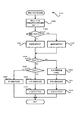
[主制御メイン処理]
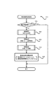
次に、図10〜図38に基づいて、遊技制御用マイコン81の動作(主制御部による制御処理)について説明する。尚、遊技制御用マイコン81の動作説明にて登場するカウンタ、フラグ、ステータス、バッファ等は、主制御基板80のRAMに設けられている。主制御基板80に備えられた遊技制御用マイコン81は、パチンコ遊技機1の電源がオンされると、主制御基板80のROMから図10に示した主制御メイン処理のプログラムを読み出して実行する。同図に示すように、主制御メイン処理では、まず初期設定を行う(S101)。初期設定では例えば、スタックの設定、定数設定、割り込み時間の設定、主制御基板80のCPUの設定、SIO、PIO、CTC(割り込み時間用コントローラ)の設定や、各種のフラグ、ステータス及びカウンタのリセット等を行う。フラグの初期値は「0」つまり「OFF」であり、ステータスの初期値は「1」であり、カウンタの初期値は「0」である。尚、初期設定(S101)は、電源投入後に一度だけ実行され、それ以降は実行されない。
[Main control main processing]
Next, the operation (control processing by the main control unit) of the
初期設定(S101)に次いで、割り込みを禁止し(S102)、普通図柄・特別図柄主要乱数更新処理(S103)を実行する。この普通図柄・特別図柄主要乱数更新処理(S103)では、図7に示した種々の乱数カウンタの値を1加算する更新を行う。各乱数カウンタの値は上限値に至ると「0」に戻って再び加算される。尚各乱数カウンタの初期値は「0」以外の値であってもよく、ランダムに変更されるものであってもよい。更新された乱数カウンタ値は主制御基板80のRAMの所定の更新値記憶領域(図示せず)に逐次記憶される。
Following the initial setting (S101), interrupts are disabled (S102), and normal symbol / special symbol main random number update processing (S103) is executed. In this normal symbol / special symbol main random number update process (S103), the values of the various random number counters shown in FIG. 7 are updated by one. When the value of each random number counter reaches the upper limit, it returns to "0" and is added again. The initial value of each random number counter may be a value other than "0" or may be randomly changed. The updated random number counter values are sequentially stored in a predetermined updated value storage area (not shown) of the RAM of the
普通図柄・特別図柄主要乱数更新処理(S103)が終了すると、割り込みを許可する(S104)。割り込み許可中は、割り込み処理(S105)の実行が可能となる。この割り込み処理(S105)は、例えば4ms周期で主制御基板80のCPUに繰り返し入力される割り込みパルスに基づいて実行される。そして、割り込み処理(S105)が終了してから、次に割り込み処理(S105)が開始されるまでの間に、普通図柄・特別図柄主要乱数更新処理(S103)による各種カウンタ値の更新処理が繰り返し実行される。尚、割り込み禁止状態のときにCPUに割り込みパルスが入力された場合は、割り込み処理(S105)はすぐには開始されず、割り込み許可(S104)がされてから開始される。
When the normal symbol / special symbol main random number update process (S103) is completed, the interrupt is enabled (S104). While interrupts are enabled, interrupt processing (S105) can be executed. This interrupt processing (S105) is executed based on an interrupt pulse that is repeatedly input to the CPU of the
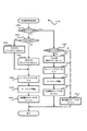
[割り込み処理]
次に、割り込み処理(S105)について説明する。図11に示すように、割り込み処理(S105)では、まず出力処理(S201)を実行する。出力処理(S201)では、以下に説明する各処理において主制御基板80のRAMに設けられた出力バッファにセットされたコマンド(制御信号)等を、サブ制御基板90や払出制御基板110等に出力する。ここで出力するコマンド等には、遊技状態、特別図柄当否判定の結果、大当り種別としての図柄、変動パターン等に関する情報等が挙げられる。尚、コマンドは、例えば2バイトの情報からなる。上位1バイトは、コマンドの種類に関する情報であり、下位1バイトはコマンドの内容に関する情報である。
[Interrupt processing]
Next, interrupt processing (S105) will be described. As shown in FIG. 11, in the interrupt processing (S105), the output processing (S201) is first executed. In the output process (S201), commands (control signals) set in the output buffer provided in the RAM of the
出力処理(S201)に次いで行われる入力処理(S202)では、主にパチンコ遊技機1に取り付けられている各種センサ(第1始動口センサ20a、第2始動口センサ21a、第1大入賞口センサ30a、第2大入賞口センサ35a、一般入賞口センサ27a等(図5を参照))が検知した検知信号を読み込み、賞球情報としてRAMの出力バッファに記憶する。また、第1始動口センサ20aや第2始動口センサ21aが遊技球を検知した場合、後述の始動入球時処理(S205)により、各始動口に対応する始動入球コマンドをRAMの出力バッファに記憶する。さらに、下皿62の満杯を検知する下皿満杯スイッチからの検知信号も取り込み、下皿満杯データとしてRAMの出力バッファに記憶する。
In the input process (S202) performed after the output process (S201), various sensors (first
次に行われる普通図柄・特別図柄主要乱数更新処理(S203)は、図10の主制御メイン処理で行う普通図柄・特別図柄主要乱数更新処理(S103)と同じである。即ち、図7に示した各種乱数カウンタ値(普通図柄乱数カウンタ値も含む)の更新処理は、タイマ割り込み処理(S105)の実行期間と、それ以外の期間(割り込み処理(S105)の終了後、次の割り込み処理(S105)が開始されるまでの期間)との両方で行われている。 The normal symbol / special symbol main random number update process (S203) performed next is the same as the normal symbol / special symbol main random number update process (S103) performed in the main control main process of FIG. That is, the update processing of various random number counter values (including the normal symbol random number counter value) shown in FIG. 7 is performed after the execution period of the timer interrupt processing (S105) and the other periods (after the end of the interrupt processing (S105)). It is performed both in the period until the next interrupt processing (S105) is started).
普通図柄・特別図柄主要乱数更新処理(S203)に次いで、後述する始動口センサ検知処理(S204)、始動入球時処理(S205)、普図動作処理(S206)、特図動作処理(S207)、特定領域センサ検知処理(S208)、保留球数処理(S209)および電源断監視処理(S210)を実行する。この他、遊技を進行させる上で必要な「その他の処理」を実行して、割り込み処理(S105)を終了する。そして、次に主制御基板80のCPUに割り込みパルスが入力されるまで主制御メイン処理のS102〜S104の処理が繰り返し実行され(図10を参照)、割り込みパルスが入力されると(約4msec後)、再び割り込み処理(S105)が実行される。再び実行された割り込み処理(S105)の出力処理(S201)においては、前回の割り込み処理(S105)にてRAMの出力バッファにセットされたコマンド等が出力される。 Following the normal symbol / special symbol main random number update process (S203), the start port sensor detection process (S204), start ball entry process (S205), normal diagram operation process (S206), and special symbol operation process (S207), which will be described later. , Specific area sensor detection process (S208), hold ball number process (S209), and power failure monitoring process (S210) are executed. In addition, the interrupt processing (S105) is terminated by executing "other processing" necessary for advancing the game. Then, the processes S102 to S104 of the main control main process are repeatedly executed until the interrupt pulse is input to the CPU of the main control board 80 (see FIG. 10), and when the interrupt pulse is input (after about 4 msec). ), Interrupt processing (S105) is executed again. In the output process (S201) of the interrupt process (S105) executed again, the command or the like set in the output buffer of the RAM in the previous interrupt process (S105) is output.
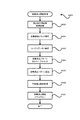
[始動口センサ検知処理]
図12に示すように、始動口センサ検知処理(S204)では、まず、遊技球がゲート28を通過したか否か、即ち、ゲートセンサ28aによって遊技球が検知されたか否かを判定する(S301)。遊技球がゲート28を通過していなければ(S301でNO)、S305の処理に移行し、ゲート28を遊技球が通過していれば(S301でYES)、普通図柄保留球数(普図保留の数、具体的にはRAMに設けた普図保留の数をカウントするカウンタの値)が4未満であるか否か判定する(S302)。
[Starting port sensor detection process]
As shown in FIG. 12, in the start port sensor detection process (S204), first, it is determined whether or not the game ball has passed through the
普通図柄保留球数が4未満でなければ(S302でNO)、S305の処理に移行する。一方、普通図柄保留球数が4未満であれば(S302でYES)、普通図柄保留球数に「1」を加算し(S303)、普通図柄乱数取得処理(S304)を行う。普通図柄乱数取得処理(S304)では、RAMの更新値記憶領域(図示せず)に記憶されている普通図柄当否判定用乱数カウンタの値(ラベル−TRND−H、図7(B))を取得し、その取得乱数値(取得情報)を、主制御基板80のRAMに設けられた普図保留記憶部のうち現在の普通図柄保留球数に応じたアドレス空間に格納する。
If the number of normal symbol reserved balls is not less than 4 (NO in S302), the process proceeds to S305. On the other hand, if the number of normal symbol reserved balls is less than 4 (YES in S302), "1" is added to the number of normal symbol reserved balls (S303), and the normal symbol random number acquisition process (S304) is performed. In the normal symbol random number acquisition process (S304), the value (label-TRND-H, FIG. 7 (B)) of the random number counter for determining whether the normal symbol is correct or not, which is stored in the update value storage area (not shown) of the RAM, is acquired. Then, the acquired random number value (acquired information) is stored in the address space corresponding to the current number of ordinary symbol holding balls in the normal symbol holding storage unit provided in the RAM of the
S305では、第2始動口21に遊技球が入球したか否か、即ち、第2始動口センサ21aによって遊技球が検知されたか否かを判定する(S305)。第2始動口21に遊技球が入球していない場合(S305でNO)には、S309の処理に移行し、第2始動口21に遊技球が入球した場合には(S305でYES)、特図2保留球数(第2特図保留の数、具体的には主制御部80のRAMに設けた第2特図保留の数をカウントするカウンタの数値)が4(上限数)未満であるか否か判定する(S306)。そして、特図2保留球数が4未満でない場合(S306でNO)には、S309の処理に移行し、特図2保留球数が4未満である場合には(S306でYES)、特図2保留球数に1を加算する(S307)。
In S305, it is determined whether or not the game ball has entered the
続いて特図2関係乱数取得処理(S308)を行う。特図2関係乱数取得処理(S308)では、RAMの更新値記憶領域(図示せず)に記憶されている特別図柄当否判定用乱数カウンタの値(ラベル−TRND−A)、大当り種別決定用乱数カウンタの値(ラベル−TRND−AS)及び変動パターン乱数カウンタの値(ラベル−TRND−T1)を取得し(つまり図7(A)に示す乱数の値を取得し)、それら取得乱数値(取得情報)を第2特図保留記憶部85bのうち現在の特図2保留球数に応じたアドレス空間に格納する。 Subsequently, the special figure 2 related random number acquisition process (S308) is performed. In the special figure 2 related random number acquisition process (S308), the value (label-TRND-A) of the random number counter for determining whether the special symbol is correct or not, and the random number for determining the jackpot type, which are stored in the update value storage area (not shown) of the RAM. The counter value (label-TRND-AS) and the fluctuation pattern random number counter value (label-TRND-T1) are acquired (that is, the random number values shown in FIG. 7 (A) are acquired), and the acquired random number values (acquisition) are acquired. Information) is stored in the address space corresponding to the current number of reserved balls in the second special figure 2 in the second special figure reserved storage unit 85b.
続いて第1始動口20に遊技球が入球したか否か、即ち、第1始動口センサ20aによって遊技球が検知されたか否かを判定する(S309)。第1始動口20に遊技球が入球していない場合(S309でNO)には処理を終え、第1始動口20に遊技球が入球した場合には(S309でYES)、特図1保留球数(第1特図保留の数、具体的には主制御部80のRAMに設けた第1特図保留の数をカウントするカウンタの数値)が4(上限数)未満であるか否か判定する(S310)。そして、特図1保留球数が4未満でない場合(S310でNO)には処理を終え、特図1保留球数が4未満である場合には(S310でYES)、特図1保留球数に「1」を加算する(S311)。
Subsequently, it is determined whether or not the game ball has entered the
続いて特図1関係乱数取得処理(S312)を行う。特図1関係乱数取得処理(S312)では、特図2関係乱数取得処理(S308)と同様に、RAMの更新値記憶領域(図示せず)に記憶されている特別図柄当否判定用カウンタの値(ラベル−TRND−A)、大当り種別決定用乱数カウンタの値(ラベル−TRND−AS)および変動パターン乱数カウンタの値(ラベル−TRND−T1)を取得し(つまり図7(A)に示す乱数値を取得し)、それら取得乱数値を第1特図保留記憶部のうち現在の特図1保留球数に応じたアドレス空間に格納する。 Subsequently, the special figure 1 related random number acquisition process (S312) is performed. In the special figure 1 related random number acquisition process (S312), the value of the special symbol hit / miss determination counter stored in the update value storage area (not shown) of the RAM is the same as in the special figure 2 related random number acquisition process (S308). (Label-TRND-A), the value of the random number counter for determining the jackpot type (label-TRND-AS), and the value of the fluctuation pattern random number counter (label-TRND-T1) are acquired (that is, the disturbance shown in FIG. 7 (A)). Numerical values are acquired), and the acquired random number values are stored in the address space corresponding to the current number of reserved balls in the first special figure 1 in the first special figure reserved storage unit.
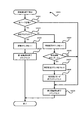
[始動入球時処理]
図11に示すように遊技制御用マイコン81は、始動口センサ検知処理(S204)に次いで始動入球時処理(S205)を行う。図13に示すように、始動入球時処理(S205)では、まず、特図2保留球数が「1」増加したか否かを判定する(S315)。そして、特図2保留球数が「1」増加したと判定した場合(S315でYES)、S316の処理に移行する。これは、第2始動口に遊技球が入球したことに基づいて、始動口センサ検知処理(S204)におけるS307で特図2保留球数に「1」を加算した場合が該当する。一方、特図2保留球数が増加していないと判定した場合(S315でNO)、S319の処理に移行する。
[Processing at the time of starting ball entry]
As shown in FIG. 11, the
S316では、直前の始動口センサ検知処理(S204)における特図2関係乱数取得処理(S308)で取得して第2特図保留記憶部に記憶した最新の取得乱数値(取得情報)を読み出す(S316)。次いで、読み出した第2特別図柄に係る取得乱数値を判定する(S317)。S317では、読み出した取得乱数値のうち、特別図柄当否判定用乱数カウンタの値(特別図柄当否判定用乱数値)については、現在の遊技状態(低確率状態か高確率状態か)に応じて大当りか外れかを判定し、当該判定の結果が大当りである場合には、さらに大当りの種別を判定する。このS317の処理は、後述の特図2当否判定処理(S1202)における当否判定(S1303,S1309)に先立って行う事前判定(所謂「保留先読み」)に相当するものである。 In S316, the latest acquired random number value (acquisition information) acquired in the special figure 2 related random number acquisition process (S308) in the immediately preceding start port sensor detection process (S204) and stored in the second special figure hold storage unit is read (acquired information). S316). Next, the acquired random number value related to the read second special symbol is determined (S317). In S317, among the acquired random number values read out, the value of the random number counter for determining whether the special symbol is correct or not (the random number value for determining whether the special symbol is correct or not) is a big hit according to the current game state (low probability state or high probability state). If the result of the determination is a big hit, the type of the big hit is further determined. This process of S317 corresponds to a preliminary determination (so-called “hold look-ahead”) performed prior to the accuracy determination (S1303, S1309) in the special figure 2 accuracy determination process (S1202) described later.
尚、大当りか否かの事前判定は、大当り判定テーブル(図8(A)を参照)、すなわち、高確率状態であれば高確率状態用の大当り判定テーブル、通常状態(低確率状態)であれば通常状態用の大当り判定テーブルに基づいて、大当り判定値と一致するか否かを判定することが可能である。また、他の事前判定態様として、変動パターン情報を判定可能な変動パターン情報判定テーブルとして、通常状態用(低確率状態用)の変動パターン情報判定テーブルと、高確率状態用(高確率状態用)の変動パターン情報判定テーブルと、を有するものとする。そして、事前判定においては、取得乱数値(特別図柄当否判定用乱数カウンタの値等)と、遊技状態に応じた変動パターン情報判定テーブルと、に基づいて、所定の変動パターン情報を選択するものとすることが可能である。そして、この選択した変動パターン情報から、大当りかどうかや大当り種別、大当り信頼度の高い遊技演出が実行されるかどうか等を識別可能とすることができる。 The pre-judgment as to whether or not it is a big hit can be made in the big hit judgment table (see FIG. 8A), that is, in the high probability state, the big hit judgment table for the high probability state, or in the normal state (low probability state). For example, it is possible to determine whether or not the value matches the jackpot determination value based on the jackpot determination table for the normal state. Further, as another pre-judgment mode, as a fluctuation pattern information judgment table capable of judging fluctuation pattern information, a fluctuation pattern information judgment table for a normal state (for a low probability state) and a fluctuation pattern information judgment table for a high probability state (for a high probability state) It is assumed that the fluctuation pattern information determination table of the above is provided. Then, in the preliminary determination, predetermined variation pattern information is selected based on the acquired random number value (value of the random number counter for determining whether or not the special symbol is correct) and the variation pattern information determination table according to the game state. It is possible to do. Then, from the selected fluctuation pattern information, it is possible to identify whether or not the game is a big hit, the type of the big hit, and whether or not a game effect with high reliability of the big hit is executed.
次いでS318では、S317による事前判定の結果に係る遊技情報(事前判定情報)、具体的には、特別図柄当否判定用乱数値が大当り判定値と一致するか否かを示す情報(当否情報)や、大当り種別決定用乱数カウンタの値(大当り種別決定用乱数値)を示す情報、変動パターン乱数カウンタの値(変動パターン乱数値)を示す情報等を含むコマンドデータを、特図2始動入球コマンドとして生成し、当該コマンドをRAMの出力バッファにセットする(S318)。尚、特図2始動入球コマンドとして、S316で読み出した特図2取得乱数の値の一部または全部を、そのままサブ制御基板に送信するようにしてもよいし、特図2取得乱数の値はそのまま送信せず、特図2取得乱数の値に基づいて取得した遊技情報(例えば、前述の変動パターン情報等)を送信するようにしてもよい。 Next, in S318, game information (preliminary judgment information) related to the result of the preliminary judgment by S317, specifically, information indicating whether or not the random number value for determining whether the special symbol is correct or not matches the jackpot determination value (win / not information) , Information indicating the value of the random number counter for determining the jackpot type (random number value for determining the jackpot type), information indicating the value of the fluctuation pattern random number counter (variation pattern random number value), etc. And set the command in the output buffer of the RAM (S318). In addition, as a special figure 2 start entry command, a part or all of the value of the special figure 2 acquisition random number read by S316 may be transmitted to the sub control board as it is, or the value of the special figure 2 acquisition random number may be transmitted as it is. Is not transmitted as it is, but game information acquired based on the value of the random number acquired in Special Figure 2 (for example, the above-mentioned fluctuation pattern information) may be transmitted.
また、主制御部80から送信した特図2始動入球コマンドをサブ制御部90で解析することで、大当りに係る情報であるかどうか、大当り種別は何れであるか、変動パターンは何れであるか等を、サブ制御部90が識別できるものとされている。また、本実施例では、これに加えて、特図2始動入球コマンドを解析することで、取得した特図2取得乱数が高確率状態で判定した場合に大当りとなるかどうか、及び低確率状態で判定した場合に大当りとなるかどうか、を特定可能とされている。これにより、サブ制御部90は、受信した特図2始動入球コマンドを保留(演出保留情報)として記憶し、特定のタイミングで当該演出保留情報を事前判定し、低確率状態で当否判定した場合に大当りと判定される演出保留情報が記憶されているかどうかを判定することが可能となる。
Further, by analyzing the special figure 2 start-in ball command transmitted from the
尚、不正防止の観点から、S316で読み出した取得乱数値のうち特別図柄当否判定用乱数値を、そのままサブ制御部に送信することはせず、その他の大当り種別決定用乱数カウンタの値(大当り種別決定用乱数値)と変動パターン乱数カウンタの値(変動パターン乱数値)を示す情報と、事前判定の結果を示す情報とを含むコマンドデータを特図2始動入球コマンドとして生成し、これをセットすることが可能である。 From the viewpoint of fraud prevention, the random number value for determining whether the special symbol is correct or not among the random number values read by S316 is not transmitted to the sub-control unit as it is, and the value of the random number counter for determining the other jackpot type (big hit). Command data including information indicating the value of the random number value for determining the type), the value of the fluctuation pattern random number counter (variation pattern random number value), and the information indicating the result of the pre-judgment is generated as the special figure 2 start entry command, and this is generated. It is possible to set.
次いでS319では、前述の特図2に係る処理と同様に、特図1保留球数が「1」増加したか否かを判定する(S319)。そして、特図1保留球数が「1」増加したと判定した場合(S319でYES)、S320の処理に移行する。これは、第1始動口に遊技球が入球したことに基づいて、始動口センサ検知処理(S204)におけるS311で特図1保留球数に「1」を加算した場合が該当する。一方、S319で、特図1保留球数が増加していないと判定した場合(S319でNO)、そのまま処理を終える。 Next, in S319, it is determined whether or not the number of reserved balls in Special Figure 1 has increased by "1" in the same manner as in the above-described processing according to Special Figure 2 (S319). Then, when it is determined that the number of reserved balls in Special Figure 1 has increased by "1" (YES in S319), the process proceeds to S320. This corresponds to the case where "1" is added to the number of reserved balls in the special figure 1 in S311 in the start port sensor detection process (S204) based on the game ball entering the first start port. On the other hand, if it is determined in S319 that the number of reserved balls in Special Figure 1 has not increased (NO in S319), the process ends as it is.
S320では、時短フラグがONであるか否かを判定し(S320)、時短フラグがONである、すなわち高ベース状態であると判定した場合(S320でYES)、そのまま処理を終える。一方、S320で時短フラグがOFFである、すなわち低ベース状態であると判定した場合(S320でNO)、S321以降の事前判定に係る処理に進む。 In S320, it is determined whether or not the time saving flag is ON (S320), and when it is determined that the time saving flag is ON, that is, it is in the high base state (YES in S320), the process is terminated as it is. On the other hand, when it is determined in S320 that the time saving flag is OFF, that is, in the low base state (NO in S320), the process proceeds to the process related to the pre-determination after S321.
S321〜S323の処理は、前述したS316〜S318と同様の処理を特図1について行うものである。すなわち、始動口センサ検知処理(S204)における特図1関係乱数取得処理(S312)で取得して第1特図保留記憶部に記憶した最新の取得乱数値(取得情報)を読み出し(S321)、読み出した取得乱数値について事前判定を行う(S322)。そして、この事前判定に係る遊技情報を含むコマンドデータを特図1始動入球コマンドとして生成し、当該コマンドをRAMの出力バッファにセットする(S323)。尚、S322の事前判定(保留先読み)は、後述の特図1当否判定処理(S1207)における当否判定(S1603,S1609)に先立って行うものである。 The processing of S321 to S323 is the same processing as that of S316 to S318 described above for the special figure 1. That is, the latest acquired random number value (acquisition information) acquired by the special figure 1 related random number acquisition process (S312) in the start port sensor detection process (S204) and stored in the first special figure hold storage unit is read (S321). Pre-determination is performed on the read acquired random number value (S322). Then, the command data including the game information related to this pre-determination is generated as the special figure 1 start entry command, and the command is set in the output buffer of the RAM (S323). The pre-determination (holding look-ahead) of S322 is performed prior to the pass / fail determination (S1603, S1609) in the special figure 1 pass / fail determination process (S1207) described later.
ここで、高ベース状態では、第2始動口21への入球頻度が高まる開放延長機能が作動しており、特図2の当否判定(図8(B)を参照)が行われやすい状態となっている。また、本実施例では、後述するように特図2保留の消化(第2特別図柄の変動表示)を特図1保留の消化(第1特別図柄の変動表示)に優先して実行するものとしている。このことから、本実施例では、特図1保留に係る事前判定(特図1事前判定)を、第1特別図柄の変動表示が主として行われる低ベース状態にて行うこととし、特図2保留に係る事前判定(特図2事前判定)については、低ベース状態であるか高ベース状態であるかを問わず行うこととしている。また、本実施例のパチンコ遊技機1では、後述するように、大当り遊技中は低確低ベース状態に制御されるが、大当り遊技中に遊技球が第1始動口20に入球して特図1保留球数が「1」増加したとしても、S321〜S323の処理(特図1事前判定処理)は行わないものとなっている。
Here, in the high base state, the opening extension function that increases the frequency of entering the
[普図動作処理]
遊技制御用マイコン81は、始動入球遊技処理(S206)に次いで、図14に示す普図動作処理(S207)を行う。普図動作処理(S207)では、普通図柄表示器42および可変入賞装置22に関する処理を4つの段階に分け、それらの各段階に「普図動作ステータス1、2、3、4」を割り当てている。そして、「普図動作ステータス」が「1」である場合には(S401でYES)、普通図柄待機処理(S402)を行い、「普図動作ステータス」が「2」である場合には(S401でNO、S403でYES)、普通図柄変動中処理(S404)を行い、「普図動作ステータス」が「3」である場合には(S401,S403で共にNO、S405でYES)、普通図柄確定処理(S406)を行い、「普図動作ステータス」が「4」である場合には(S401、S403、S405の全てがNO)、普通電動役物処理(S407)を行う。尚普図動作ステータスは、初期設定では「1」である。
[Public map operation processing]
The
[普通図柄待機処理]
図15に示すように、普通図柄待機処理(S402)では、まず、普通図柄の保留球数が「0」であるか否かを判定し(S501)、「0」であれば(S501でYES)、この処理を終える。一方「0」でなければ(S501でNO)、後述の普通図柄当否判定処理を行い(S502)、次いで、普通図柄変動パターン選択処理を行う(S503)。普通図柄変動パターン選択処理では、図8(D)に示す普通図柄変動パターン選択テーブルを参照して、遊技状態が時短状態であれば、普通図柄の変動時間が1秒の普通図柄変動パターンを選択する。一方、遊技状態が非時短状態であれば、普通図柄の変動時間が30秒の普通図柄変動パターンを選択する。普通図柄変動パターン選択処理(S503)を終えたら、後述の普通図柄乱数シフト処理(S504)を行い、次いで、普通図柄変動開始処理(S505)を行い、処理を終える。普通図柄変動開始処理では、S503で選択した普通図柄変動パターンに基づいて普通図柄の変動表示を開始するとともに、普通動作ステータスを「2」にセットする。また、普通図柄変動開始処理では、サブ制御基板90に普通図柄の変動開始を知らせるため、普通図柄変動開始コマンドをセットする。
[Normal symbol standby processing]
As shown in FIG. 15, in the normal symbol standby process (S402), first, it is determined whether or not the number of reserved balls of the normal symbol is "0" (S501), and if it is "0" (YES in S501). ), Finish this process. On the other hand, if it is not "0" (NO in S501), the normal symbol hit / miss determination process described later is performed (S502), and then the normal symbol variation pattern selection process is performed (S503). In the normal symbol variation pattern selection process, the normal symbol variation pattern selection table shown in FIG. 8 (D) is referred to, and if the game state is a time saving state, the normal symbol variation pattern having a variation time of 1 second is selected. To do. On the other hand, if the gaming state is a non-time saving state, a normal symbol variation pattern having a normal symbol variation time of 30 seconds is selected. After finishing the normal symbol variation pattern selection process (S503), the normal symbol random number shift process (S504) described later is performed, and then the normal symbol variation start process (S505) is performed to finish the process. In the normal symbol variation start process, the variation display of the normal symbol is started based on the normal symbol variation pattern selected in S503, and the normal operation status is set to "2". Further, in the normal symbol change start process, a normal symbol change start command is set in order to notify the
[普通図柄当否判定処理]
図16に示すように、普通図柄当否判定処理(S502)では、まず、普図保留記憶部に格納されている普通図柄当否判定用乱数カウンタの値(ラベル−TRND−H)を読み出す(S601)。次いで、時短フラグがONであるか否か(すなわち遊技状態が時短状態であるか否か)を判定する(S602)。S602で、時短フラグがONである、すなわち時短状態であると判定した場合(S602でYES)、図8(C)に示す普通図柄当り判定テーブルのうち時短状態用のテーブル(当り判定値が「0」〜「239」)に基づく高確率普図当否判定により、当りか否かを判定し(S604)、S605の処理に移行する。すなわち、読み出した普通図柄当否判定用乱数カウンタの値(ラベル−TRND−H)が当り判定値の何れかと一致するか否かを判定する。一方、S602で、時短フラグがONでない、すなわち、非時短状態であると判定した場合(S602でNO)、図8(C)に示す普通図柄当り判定テーブルのうち非時短状態用のテーブル(当り判定値が「0」、「1」)に基づく低確率普図当否判定により、当りか否かを判定し(S603)、S605の処理に移行する。そして、S605で、普図当否判定(S603,S604)の結果が、当り(普図当り)か否かを判定し(S605)、外れと判定された場合(S605でNO)、停止表示する外れ普通図柄(普図外れ図柄)を決定し(S606)、処理を終える。一方、S605で当り(普図当り)と判定された場合(S605でYES)、停止表示する当り普通図柄(普図当り図柄)を決定し(S607)、普図当りフラグをONにして(S608)、処理を終える。
[Ordinary symbol winning / failing judgment processing]
As shown in FIG. 16, in the normal symbol hit / miss determination process (S502), first, the value (label-TRND-H) of the normal symbol hit / miss determination random number counter stored in the normal symbol hold storage unit is read (S601). .. Next, it is determined whether or not the time saving flag is ON (that is, whether or not the gaming state is the time saving state) (S602). When it is determined in S602 that the time saving flag is ON, that is, it is in the time saving state (YES in S602), among the normal symbol hit judgment tables shown in FIG. 8 (C), the table for the time saving state (the hit judgment value is "". Based on the high-probability normal-figure hit / fail judgment based on "0" to "239"), it is judged whether or not it is a hit (S604), and the process proceeds to S605. That is, it is determined whether or not the value (label-TRND-H) of the read random number counter for determining whether or not the normal symbol is correct matches any of the hit determination values. On the other hand, when it is determined in S602 that the time saving flag is not ON, that is, it is in the non-time saving state (NO in S602), the table for the non-time saving state (hit) among the normal symbol hit judgment tables shown in FIG. 8 (C). Based on the low-probability normal-figure hit / fail judgment based on the judgment values "0" and "1"), it is judged whether or not it is a hit (S603), and the process proceeds to S605. Then, in S605, it is determined whether or not the result of the normal figure hit / fail judgment (S603, S604) is a hit (normal figure hit) (S605), and if it is judged to be a miss (NO in S605), the stop display is missed. Determine the normal symbol (the symbol that is out of the ordinary symbol) (S606), and finish the process. On the other hand, if it is determined to be a hit (per normal figure) in S605 (YES in S605), the normal symbol per stop display (design per normal figure) is determined (S607), and the normal figure hit flag is turned ON (S608). ), Finish the process.
[普通図柄乱数シフト処理]
図17に示すように、普通図柄乱数シフト処理(S504)では、まず、普通図柄保留球数を1デクリメントする(S701)。次いで、普図保留記憶部における各普図保留の格納場所を、現在の位置から読み出される側に一つシフトする(S702)。そして、普図保留記憶部における最上位の保留記憶の格納場所であるアドレス空間を空(「0」)にして、即ち普図保留の4個目に対応するRAM領域を0クリアして(S703)、処理を終える。このようにして、普図保留が保留順に消化されるようにしている。
[Ordinary symbol random number shift processing]
As shown in FIG. 17, in the normal symbol random number shift process (S504), first, the number of normal symbol reserved balls is decremented by 1 (S701). Next, the storage location of each Fuzu hold in the Fuzu hold storage unit is shifted by one to the side read from the current position (S702). Then, the address space, which is the storage location of the highest hold storage in the normal figure hold storage unit, is emptied (“0”), that is, the RAM area corresponding to the fourth hold of the normal figure is cleared to 0 (S703). ), Finish the process. In this way, the general map hold is digested in the order of hold.
[普通図柄変動中処理]
図18に示すように、普通図柄変動中処理(S404)では、まず、普通図柄の変動時間が経過したか否か判定し(S801)、経過していなければ(S801でNO)、処理を終える。一方、経過していれば(S801でYES)、普通図柄変動停止コマンドをセットする(S802)とともに、普図動作ステータスを「3」にセットする(S803)。そして、普通図柄の変動表示を、普通図柄当否判定用乱数の判定結果に応じた表示結果(当り普通図柄又は外れ普通図柄)で停止させる等のその他の処理を行って(S804)、この処理を終える。
[Processing during normal symbol change]
As shown in FIG. 18, in the normal symbol change processing (S404), first, it is determined whether or not the change time of the normal symbol has elapsed (S801), and if not (NO in S801), the process ends. .. On the other hand, if it has passed (YES in S801), the normal symbol fluctuation stop command is set (S802) and the normal symbol operation status is set to "3" (S803). Then, other processing such as stopping the variable display of the normal symbol at the display result (hit normal symbol or out-of-order normal symbol) according to the judgment result of the random number for determining whether or not the normal symbol is correct is performed (S804), and this processing is performed. Finish.
[普通図柄確定処理]
図19に示すように、普通図柄確定処理(S406)では、まず、普図当りフラグがONであるか否かを判定する(S901)。普図当りフラグがONでなければ(S901でNO)、普図動作ステータスを「1」にセットして(S905)、この処理を終える。一方、普図当りフラグがONであれば(S901でYES)、続いて時短フラグがONであるか否か、すなわち時短状態中か否かを判定する(S902)。そして、時短状態中であれば(S902でYES)、可変入賞装置22(第2始動口21)の開放パターンとして時短状態中の開放パターンをセットする(S903)。時短状態中の開放パターンとは、前述の通り、2.0秒の開放を3回繰り返す開放パターンである。従って、第2始動口21の開放回数をカウントする第2始動口開放カウンタに「3」をセットする。
[Normal symbol confirmation process]
As shown in FIG. 19, in the normal symbol determination process (S406), first, it is determined whether or not the normal symbol hit flag is ON (S901). If the normal map hit flag is not ON (NO in S901), the normal figure operation status is set to "1" (S905), and this process ends. On the other hand, if the flag per normal figure is ON (YES in S901), then it is determined whether or not the time saving flag is ON, that is, whether or not the time saving state is in progress (S902). Then, if it is in the time saving state (YES in S902), the opening pattern in the time saving state is set as the opening pattern of the variable winning device 22 (second starting port 21) (S903). As described above, the opening pattern in the time saving state is an opening pattern in which the opening for 2.0 seconds is repeated three times. Therefore, "3" is set in the second starting port opening counter that counts the number of times the
これに対して、非時短状態中であれば(S902でNO)、可変入賞装置22(第2始動口21)の開放パターンとして非時短状態中の開放パターンをセットする(S906)。非時短状態中の開放パターンとは、前述の通り、0.2秒の開放を1回行う開放パターンである。従って、第2始動口開放カウンタに「1」をセットする。そして、開放パターンのセット(S903、S906)に続いて、普図動作ステータスを「4」にセットし(S904)、この処理を終える。 On the other hand, if it is in the non-time saving state (NO in S902), the opening pattern in the non-time saving state is set as the opening pattern of the variable winning device 22 (second starting port 21) (S906). As described above, the opening pattern in the non-time saving state is an opening pattern in which opening for 0.2 seconds is performed once. Therefore, "1" is set in the second start port opening counter. Then, following the set of the open pattern (S903, S906), the normal figure operation status is set to "4" (S904), and this process is completed.
[普通電動役物処理]
図20に示すように、普通電動役物処理(S407)では、まず、普図当り終了フラグがONであるか否かを判定する(S1001)。普図当り終了フラグは、当りとなって実行された補助遊技において、第2始動口21の開放が終了したことを示すフラグである。
[Ordinary electric accessory processing]
As shown in FIG. 20, in the ordinary electric accessory processing (S407), first, it is determined whether or not the end flag per normal figure is ON (S1001). The normal figure hit end flag is a flag indicating that the opening of the
普図当り終了フラグがONでなければ(S1001でNO)、第2始動口21の開放中か否かを判定する(S1002)。開放中でなければ(S1002でNO)、第2始動口21を開放させる時期(タイミング)に至ったか否かを判定し(S1003)、至っていなければ(S1003でNO)、処理を終え、至っていれば(S1003でYES)、第2始動口21を開放させ(S1004)、処理を終える。一方、第2始動口21の開放中であれば(S1002でYES)、第2始動口21を閉鎖させる時期(タイミング)に至ったか否か(すなわち第2始動口21を開放してから予め定められた開放時間が経過したか否か)を判定し(S1005)、至っていなければ(S1005でNO)処理を終え、至っていれば(S1005でYES)、第2始動口21を閉状態(閉鎖)とする(S1006)。
If the end flag per normal figure is not ON (NO in S1001), it is determined whether or not the
そして、第2始動口21の閉鎖処理(S1006)に次いで、第2始動口開放カウンタの値を1デクリメントし(S1007)、第2始動口開放カウンタの値が「0」であるか否か判定する(S1008)。「0」でなければ(S1008でNO)、再び第2始動口21を開放させるためにそのまま処理を終える。一方「0」であれば(S1008でYES)、補助遊技を終了させる普図当り終了処理を行う(S1009)とともに、普図当り終了フラグをセットして(S1010)処理を終える。尚、第2始動口開放カウンタは、時短状態中であれば第2始動口21の開放(可動部材23の開放動作)が3回なされると「0」になり、非時短状態中であれば第2始動口21の開放が1回なされると「0」になる。
Then, following the closing process of the second starting port 21 (S1006), the value of the second starting port opening counter is decremented by 1 (S1007), and it is determined whether or not the value of the second starting port opening counter is "0". (S1008). If it is not "0" (NO in S1008), the process is finished as it is in order to open the
これに対して、S1001において普図当り終了フラグがONであれば(S1001でYES)、S903またはS906にてセットされた回数の第2始動口21の開放動作は終了しているので、普図当り終了フラグをOFFにするとともに(S1011)、普図当りフラグをOFFにし(S1012)、普図動作ステータスを「1」にセットして(S1013)処理を終える。これにより、次回の割り込み処理において、普図動作処理(図13)として再び普通図柄待機処理(S402)が実行されることになる。
On the other hand, if the end flag per normal figure is ON in S1001 (YES in S1001), the opening operation of the
[普通電動役物処理]
図20に示すように、普通電動役物処理(S407)では、まず、普図当り終了フラグがONであるか否かを判定する(S1001)。普図当り終了フラグは、当りとなって実行された補助遊技において、第2始動口21の開放が終了したことを示すフラグである。普図当り終了フラグがONでなければ(S1001でNO)、第2始動口21の開放中か否かを判定する(S1002)。開放中でなければ(S1002でNO)、第2始動口21を開放させる時期(タイミング)に至ったか否かを判定し(S1003)、至っていなければ(S1003でNO)処理を終え、至っていれば第2始動口21を開放させ(S1004)、処理を終える。一方、第2始動口21の開放中であれば(S1002でYES)、第2始動口21を閉鎖させる時期(タイミング)に至ったか否か(すなわち第2始動口21を開放してから予め定められた開放時間が経過したか否か)を判定し(S1005)、至っていなければ(S1005でNO)処理を終え、至っていれば(S1005でYES)第2始動口21を閉状態(閉鎖)とする(S1006)。
[Ordinary electric accessory processing]
As shown in FIG. 20, in the ordinary electric accessory processing (S407), first, it is determined whether or not the end flag per normal figure is ON (S1001). The normal figure hit end flag is a flag indicating that the opening of the
そして第2始動口21の閉鎖処理(S1006)に次いで、第2始動口開放カウンタの値を1デクリメントし(S1007)、第2始動口開放カウンタの値が「0」であるか否かを判定する(S1008)。「0」でなければ(S1008でNO)、再び第2始動口21を開放させるためにそのまま処理を終える。一方「0」であれば(S1008でYES)、補助遊技を終了させる普図当り終了処理を行う(S1009)とともに、普図当り終了フラグをセットして(S1010)処理を終える。尚、第2始動口開放カウンタは、時短状態中であれば第2始動口21の開放(可動部材23の開放動作)が3回なされると「0」になり、非時短状態中であれば第2始動口21の開放が1回なされると「0」になる。
Then, following the closing process of the second starting port 21 (S1006), the value of the second starting port opening counter is decremented by 1 (S1007), and it is determined whether or not the value of the second starting port opening counter is "0". (S1008). If it is not "0" (NO in S1008), the process is finished as it is in order to open the
これに対してS1001において普図当り終了フラグがONであれば(S1001でYES)、S903又はS906にてセットされた回数の第2始動口21の開放動作は終了しているので、普図当り終了フラグをOFFするとともに(S1011)、普図当りフラグをOFFし(S1012)、普図動作ステータスを「1」にセットして(S1013)処理を終える。これにより、次回の割り込み処理において、普図動作処理(図13)として再び普通図柄待機処理(S402)が実行されることになる。
On the other hand, if the end flag for hitting the normal figure is ON in S1001 (YES in S1001), the opening operation of the
[特図動作処理]
図11に示すように遊技制御用マイコン81は、普図動作処理(S206)に次いで特図動作処理(S207)を行う。図21に示すように、特図動作処理(S207)では、特別図柄表示器41および大入賞装置(第1大入賞装置31および第2大入賞装置36)に関する処理を5つの段階に分け、それらの各段階に「特図動作ステータス1、2、3、4、5」を割り当てている。そして、特図動作ステータスが「1」である場合(S1101でYES)には特別図柄待機処理(S1102)、特図動作ステータスが「2」である場合(S1101でNO、S1103でYES)には特別図柄変動中処理(S1104)、特図動作ステータスが「3」である場合(S1101,S1103で共にNO、S1105でYES)には特別図柄確定処理(S1106)、特図動作ステータスが「4」である場合(S1101,S1103,S1105で共にNO、S1107でYES)には大当り遊技としての特別電動役物処理1(S1108)、特図動作ステータスが「5」である場合(S1101,S1103,S1105,S1107の全てがNO)には小当り遊技としての特別電動役物処理2(S1109)、をそれぞれ行う。尚、特図動作ステータスは、初期設定では「1」である。
[Special figure operation processing]
As shown in FIG. 11, the
[特別図柄待機処理]
図22に示すように、特別図柄待機処理(S1102)では、まず、第2始動口21の保留球数(即ち特図2保留球数)が「0」であるか否かを判定する(S1201)。特図2保留球数が「0」である場合(S1201でYES)、即ち、第2始動口21への入球に基づいて取得される乱数カウンタ値の記憶がない場合には、第1始動口20の保留球数(即ち特図1保留球数)が「0」であるか否かを判定する(S1206)。そして、特図1保留球数も「0」である場合(S1206でYES)、即ち、第1始動口20への入球に基づいて取得される乱数カウンタ値の記憶もない場合には、画像表示装置の表示画面を待機画面とする処理中(客待ち用のデモ画面の実行中)であるか否かを判定し(S1211)、処理中であれば(S1211でYES)、処理を終え、処理中でなければ(S1211でNO)、待機画面を表示するために待機画面設定処理を実行する(S1212)。
[Special symbol standby processing]
As shown in FIG. 22, in the special symbol standby process (S1102), first, it is determined whether or not the number of reserved balls in the second starting port 21 (that is, the number of reserved balls in special figure 2) is “0” (S1201). ). Special figure 2 When the number of reserved balls is "0" (YES in S1201), that is, when the random number counter value acquired based on the entry into the
S1201において特図2保留球数が「0」でない場合(S1201でNO)、即ち、第2始動口21への入球に基づいて取得される乱数カウンタ値の記憶が1つ以上ある場合には、後述の特図2当否判定処理(S1202)、特図2変動パターン選択処理(S1203)、特図2乱数シフト処理(S1204)、特図2変動開始処理(S1205)をこの順に行う。また、特図2保留球数が「0」であるが特図1保留球数が「0」でない場合(S1201でYES、S1206でNO)、即ち、第2始動口21に係る乱数カウンタ値の記憶はないが、第1始動口20への入球に基づいて取得される乱数カウンタ値の記憶が1つ以上ある場合には、後述の特図1当否判定処理(S1207)、特図1変動パターン選択処理(S1208)、特図1乱数シフト処理(S1209)、特図1変動開始処理(S1210)をこの順に行う。このように本実施例では、第1特図保留に基づく第1特別図柄の変動表示は、特図2保留球数が「0」の場合(S1201でYESの場合)に限って行われる。すなわち第2特図保留の消化(第2特別図柄の変動表示)は、第1特図保留の消化(第1特別図柄の変動表示)に優先して実行される。そして、本実施例では、第2特図保留に基づく当否判定の方が、第1特図保留に基づく当否判定よりも、遊技者にとって利益の大きい大当りになりやすくなっている(図8(B)を参照)。
In S1201, when the number of reserved balls in Special Figure 2 is not "0" (NO in S1201), that is, when there is one or more memory of the random number counter value acquired based on the entry into the
[特図2当否判定処理]
図23に示すように、特図2当否判定処理(S1202)では、まず、判定値として、RAMの特図保留記憶部の最下位の領域(即ち第2特図保留の1個目に対応するRAM領域)に記憶されている(最も古い記憶の)特別図柄当否判定用乱数カウンタの値(ラベル−TRND−A)を読み出す(S1301)。次いで、確変フラグがONか否か、すなわち高確率状態であるか否かを判定する(S1302)。そして、高確率状態でなければ(S1302でNO)、すなわち通常状態であれば、当り判定テーブル(図8(A)を参照)のうち通常状態用の当り判定テーブル(大当り判定値が「3」、「397」)に基づいて当否判定を行う(S1303)。一方、高確率状態であれば(S1302でYES)、当り判定テーブル(図8(A)を参照)のうち高確率状態用の大当り判定テーブルに基づいて当否判定を行う(S1309)。高確率状態用の大当り判定テーブルでは、大当り判定値が「3」、「53」、「113」、「173」、「227」、「281」、「337」、「397」、「449」、「503」とされている。
[Special Figure 2 Win / Loss Judgment Process]
As shown in FIG. 23, in the special figure 2 hit / miss determination process (S1202), first, as the determination value, it corresponds to the lowest area of the special figure hold storage unit of the RAM (that is, the first one of the second special figure hold). The value (label-TRND-A) of the random number counter for determining whether the special symbol is correct or not (the oldest stored) stored in the RAM area) is read out (S1301). Next, it is determined whether or not the probability variation flag is ON, that is, whether or not it is in a high probability state (S1302). Then, if it is not in the high probability state (NO in S1302), that is, if it is in the normal state, the hit judgment table for the normal state (the jackpot judgment value is "3"" in the hit judgment table (see FIG. 8A). , "397")) to make a pass / fail judgment (S1303). On the other hand, if it is in the high probability state (YES in S1302), the hit / fail judgment is performed based on the jackpot determination table for the high probability state in the hit determination table (see FIG. 8A) (S1309). In the jackpot determination table for high probability states, the jackpot determination values are "3", "53", "113", "173", "227", "281", "337", "397", "449", It is said to be "503".
当否判定(S1303,S1309)の結果が「大当り」であると判定した場合(S1304でYES)、大当り種別決定用乱数カウンタの値(ラベル−TRND−AS)を読み出して、図8(B)に示す大当り種別判定テーブルに基づいて大当り種別を判定し(S1310)、当該大当り種別決定用乱数の値に基づいて大当り図柄を決定し(S1311)、大当りフラグをONにして(S1312)、処理を終える。尚、第1特別図柄に係る当否判定の場合は、第1特別図柄用の大当り種別判定テーブルを用いて大当り種別を判定し、第2特別図柄に係る当否判定の場合は、第2特別図柄用の大当り種別判定テーブルを用いて大当り種別を判定する。そして、第1特別図柄(特図1)の当否判定にて大当りと判定した場合は、15R第1大当り、15R第2大当り、15R第3大当り及び2R第4大当りのうち何れかとされ、第2特別図柄(特図2)の当否判定にて大当りと判定した場合は、15R第5大当りまたは15R第6大当りとされる(図8(B)を参照)。 When it is determined that the result of the hit / fail judgment (S1303, S1309) is "big hit" (YES in S1304), the value (label-TRND-AS) of the random number counter for determining the big hit type is read out and shown in FIG. 8 (B). The jackpot type is determined based on the jackpot type determination table shown (S1310), the jackpot symbol is determined based on the value of the random number for determining the jackpot type (S1311), the jackpot flag is turned ON (S1312), and the process is completed. .. In addition, in the case of the hit / fail judgment related to the first special symbol, the jackpot type is judged using the jackpot type judgment table for the first special symbol, and in the case of the hit / fail judgment related to the second special symbol, it is for the second special symbol. The jackpot type is determined using the jackpot type determination table of. Then, when it is determined as a big hit in the hit / fail judgment of the first special symbol (special figure 1), it is regarded as one of 15R first big hit, 15R second big hit, 15R third big hit and 2R fourth big hit, and the second When it is determined that the special symbol (Special Figure 2) is a big hit, it is considered as a 15R 5th big hit or a 15R 6th big hit (see FIG. 8 (B)).
このことに対応して、本実施例では、大当りフラグとして、大当りの種別が15R第1大当り、15R第2大当り、15R第3大当り、15R第5大当り又は15R第6大当りであった場合にONにする長当りフラグと、2R第4大当りであった場合にONにする短当りフラグと設けている。そして、2R第4大当りとなって短当りフラグがONにされると、2R第4大当り図柄が確定表示するタイミングで、ラウンド表示器45の2R用ランプ(図4を参照)の方が点灯表示される。具体的には、「2R▲15R△」(例えば、▲:点灯、△:消灯とする)の様な表示態様となる。また、15R第1〜第3大当り、15R第5大当り及び15R第6大当りの何れかとなって長当りフラグがONにされると、対応する大当り図柄が確定表示するタイミングで、15R用ランプ(図4を参照)の方が点灯表示される。具体的には、「2R△15R▲」の様な表示態様となる。
Corresponding to this, in this embodiment, as a jackpot flag, it is turned ON when the type of jackpot is 15R 1st jackpot, 15R 2nd jackpot, 15R 3rd jackpot, 15R 5th jackpot or 15R 6th jackpot. A long hit flag to be set and a short hit flag to be turned ON when the 2R 4th big hit is provided. Then, when the 2R 4th jackpot is reached and the short hit flag is turned ON, the 2R lamp (see FIG. 4) of the
ここで、大当り判定(特別図柄当否判定)や大当り種別決定判定を、夫々「判定」といってもよいし、大当り判定を行い何れの大当り図柄となるかを含めて「判定」といってもよい。また、これらの結果を「判定結果」ということもある。 Here, the jackpot judgment (special symbol hit / fail judgment) and the jackpot type determination judgment may be referred to as "judgment", respectively, or may be referred to as "judgment" including which jackpot symbol will be obtained by performing the jackpot judgment. Good. In addition, these results may be referred to as "judgment results".
一方、当否判定(S1303,S1309)の結果が「大当り」でないと判定した場合(S1304でNO)、小当りであるか否かを判定する(S1305)。すなわち、特別図柄当否判定用乱数カウンタの値(ラベル−TRND−A)が、小当り判定値である「101」〜「105」の何れかと一致するか否かを判定する(図8(A)を参照)。そして、「小当り」でないと判定した場合(S1305でNO)、外れ図柄を決定し(S1308)、処理を終える。つまり、当否判定(S1303,S1309)の結果が「大当り」でもなく「小当り」でもない場合は、その結果は「外れ」となる。一方、小当り判定(S1305)の結果が「小当り」であると判定した場合(S1305でYES)、小当り図柄を決定し(S1306)、小当りフラグをONにして(S1307)、処理を終える。尚、小当りか否かを決める乱数を、特別図柄当否判定用乱数とは別に設けてもよい。 On the other hand, when it is determined that the result of the hit / fail determination (S1303, S1309) is not a "big hit" (NO in S1304), it is determined whether or not it is a small hit (S1305). That is, it is determined whether or not the value (label-TRND-A) of the random number counter for determining whether the special symbol is correct or not matches any of the small hit determination values "101" to "105" (FIG. 8 (A)). See). Then, when it is determined that it is not a "small hit" (NO in S1305), the out-of-order symbol is determined (S1308), and the process is completed. That is, if the result of the hit / fail judgment (S1303, S1309) is neither a "big hit" nor a "small hit", the result is "missing". On the other hand, when it is determined that the result of the small hit determination (S1305) is "small hit" (YES in S1305), the small hit symbol is determined (S1306), the small hit flag is turned ON (S1307), and the process is performed. Finish. In addition, a random number for determining whether or not it is a small hit may be provided separately from the random number for determining whether or not the special symbol is correct.
[特図2変動パターン選択処理]
特別図柄待機処理(図22を参照)では、特図2当否判定処理(S1202)に次いで、特図2変動パターン選択処理を行う(S1203)。図24及び図25に示すように、特図2変動パターン選択処理(S1203)では、まず、遊技状態が時短状態であるか否か(時短フラグがONであるか否か)を判定する(S1401)。そして、時短状態でなければ(S1401でNO)、すなわち非時短状態であれば、大当りフラグがONであるか否かを判定し(S1402)、ONであれば(S1402でYES)、非時短状態中大当り用テーブル(図9に示す変動パターンテーブルのうち非時短状態かつ大当りに該当する部分)を参照して、変動パターン乱数カウンタ値(ラベル−TRND−T1)に基づいて変動パターンを選択する(S1403)。尚、変動パターンが決まれば変動時間も決まる。また、本実施例では、非時短状態中大当り用テーブルは、大当りが長当り(15R大当り)か短当り(2R大当り)かによっても分かれている(図9を参照)。しかし、本処理は、特図2についての変動パターン選択処理であり、特図2の抽選にて当選する大当りには15R第5大当り(長当り)しか存在しない(図6を参照)。したがって、本処理にて参照される箇所は、常に長当りの箇所となり、変動パターンP1またはP2が選択される。尚、非時短状態中大当り用テーブルは、長当り用と短当り用とに分かれていなくてもよい。これは後述の時短状態中大当り用テーブルについても同様である。
[Special figure 2 fluctuation pattern selection process]
In the special symbol standby process (see FIG. 22), the special figure 2 variation pattern selection process is performed (S1203) after the special figure 2 hit / fail determination process (S1202). As shown in FIGS. 24 and 25, in the special figure 2 variation pattern selection process (S1203), first, it is determined whether or not the game state is the time saving state (whether or not the time saving flag is ON) (S1401). ). Then, if it is not in the time saving state (NO in S1401), that is, if it is in the non-time saving state, it is determined whether or not the jackpot flag is ON (S1402), and if it is ON (YES in S1402), it is in the non-time saving state. The fluctuation pattern is selected based on the fluctuation pattern random number counter value (label-TRND-T1) with reference to the medium / big hit table (the portion of the fluctuation pattern table shown in FIG. 9 that corresponds to the non-time saving state and the big hit) (the fluctuation pattern random number counter value (label-TRND-T1)). S1403). If the fluctuation pattern is decided, the fluctuation time is also decided. Further, in this embodiment, the non-time-saving medium-big hit table is also divided according to whether the big hit is a long hit (15R big hit) or a short hit (2R big hit) (see FIG. 9). However, this process is a variation pattern selection process for the special figure 2, and only the 15R fifth big hit (long hit) exists in the big hit won in the lottery of the special figure 2 (see FIG. 6). Therefore, the portion referred to in this process is always the location of the long hit, and the variation pattern P1 or P2 is selected. The table for medium and large hits in the non-time saving state does not have to be divided into a long hit table and a short hit table. This also applies to the table for medium and large hits in a time-saving state, which will be described later.
一方、大当りフラグがONでなければ(S1402でNO)、小当りフラグがONであるか否かを判定する(S1405)。そして、小当りフラグがONであれば(S1405でYES)、非時短状態中小当り用テーブル(図9に示す変動パターンテーブルのうち非時短状態かつ小当りに該当する部分)を参照して、変動パターン乱数カウンタ値に基づいて変動パターンを選択する(S1409)。具体的には、本実施例では必ず変動パターンP4が選択される。 On the other hand, if the big hit flag is not ON (NO in S1402), it is determined whether or not the small hit flag is ON (S1405). Then, if the small hit flag is ON (YES in S1405), the variation is made with reference to the non-time saving state medium / small hit table (the portion of the fluctuation pattern table shown in FIG. Pattern A variation pattern is selected based on the random number counter value (S1409). Specifically, in this embodiment, the variation pattern P4 is always selected.
また、小当りフラグがONでなければ(S1405でNO)、大当りでもなく小当りでもない外れということになり、この場合、第2特別図柄の保留数が「1」又は「2」であるか否かを判定する(S1406)。ここでいう保留数とは、本処理により変動パターンを決定している情報も含めた記憶数であるので、保留記憶の数は「1」〜「4」の何れかの値とされる。そして、S1406で、保留数が「1」又は「2」であると判定した場合(S1406でYES)、非時短状態中第1保留数外れ用テーブル(図9に示す変動パターンテーブルのうち非時短状態かつ外れかつ保留球数「1,2」に該当する部分)を参照して、変動パターン乱数カウンタ値(ラベル−TRND−T1)に基づいて変動パターンを選択する(S1407)。本実施例では、変動パターンP5乃至P8の何れかが選択される。 Also, if the small hit flag is not ON (NO in S1405), it means that it is neither a big hit nor a small hit. In this case, is the number of holdings of the second special symbol "1" or "2"? Determine if not (S1406). Since the number of holdings referred to here is the number of storages including the information for which the fluctuation pattern is determined by this processing, the number of holdingss is set to any value of "1" to "4". Then, when it is determined in S1406 that the number of holds is "1" or "2" (YES in S1406), the table for removing the number of first hold during the non-time saving state (the non-time saving of the fluctuation pattern table shown in FIG. 9). The fluctuation pattern is selected based on the fluctuation pattern random number counter value (label-TRND-T1) with reference to the state, the deviation, and the portion corresponding to the number of reserved balls "1, 2" (S1407). In this embodiment, any of the fluctuation patterns P5 to P8 is selected.
一方、S1406で、保留数が「1」又は「2」でない、すなわち「3」又は「4」であると判定した場合(S1406でNO)、非時短状態中第2保留数外れ用テーブル(図9に示す変動パターンテーブルのうち非時短状態かつ外れかつ保留球数「3,4」に該当する部分)を参照して、変動パターン乱数カウンタ値(ラベル−TRND−T1)に基づいて変動パターンを選択する(S1408)。本実施例では、変動パターンP9乃至P12の何れかが選択される。ここで、非時短状態中の第1保留数外れ用テーブルは、第2保留数外れ用テーブルよりも、比較的長時間の変動時間の変動パターンを選択する可能性が高く設定されている。また、選択可能な最短の変動時間(12000ms)も、第2保留数外れ用テーブルのもの(4000ms)よりも長い時間とされている。つまり、外れ時には、保留球数に応じた短縮変動の機能が働くようになっており、特別図柄の保留球数が「3」又は「4」であるときは、特別図柄の保留球数が「1」又は「2」であるときに比して変動時間の短い変動パターンが選択されるようになっている。
On the other hand, when it is determined in S1406 that the number of holds is not "1" or "2", that is, "3" or "4" (NO in S1406), the table for removing the number of
また、前述のS1401において、遊技状態が時短状態であると判定した場合(S1401でYES)、大当りフラグがONであるか否かを判定する(図25のS1410)。そして、大当りフラグがONであると判定した場合(S1410でYES)、時短状態中大当り用テーブル(図9に示す変動パターンテーブルのうち時短状態かつ大当りに該当する部分)を参照して、変動パターン乱数カウンタ値(ラベル−TRND−T1)に基づいて変動パターンを選択する(S1411)。前述したように、本処理は、特図2についての変動パターン選択処理であり、特図2の抽選にて当選する大当りには15R第5大当り(長当り)しか存在しないことから(図6を参照)、S1411では、長当りに対応する変動パターンP13またはP14が選択される。 Further, in the above-mentioned S1401, when it is determined that the gaming state is the time saving state (YES in S1401), it is determined whether or not the jackpot flag is ON (S1410 in FIG. 25). Then, when it is determined that the jackpot flag is ON (YES in S1410), the fluctuation pattern is referred to in the time-saving state medium jackpot table (the portion of the fluctuation pattern table shown in FIG. 9 that corresponds to the time-saving state and jackpot). The variation pattern is selected based on the random number counter value (label-TRND-T1) (S1411). As described above, this process is a variation pattern selection process for the special figure 2, and since there is only a 15R fifth big hit (long hit) in the big hit won in the lottery of the special figure 2 (FIG. 6). (See), in S1411, the variation pattern P13 or P14 corresponding to the long hit is selected.
一方、S1410で大当りフラグがONでないと判定した場合(S1410でNO)、小当りフラグがONであるか否かを判定する(S1412)。そして、小当りフラグがONであれば(S1412でYES)、時短状態中小当り用テーブル(図9に示す変動パターンテーブルのうち時短状態かつ小当りに該当する部分)を参照して、変動パターン乱数カウンタ値に基づいて変動パターンを選択する(S1416)。具体的には、本実施例では必ず変動パターンP16が選択される。 On the other hand, when it is determined in S1410 that the big hit flag is not ON (NO in S1410), it is determined whether or not the small hit flag is ON (S1412). Then, if the small hit flag is ON (YES in S1412), the variable pattern random number is referred to in the time-saving state medium-small hit table (the part of the fluctuation pattern table shown in FIG. 9 that corresponds to the time-saving state and small hit). The fluctuation pattern is selected based on the counter value (S1416). Specifically, in this embodiment, the variation pattern P16 is always selected.
また、S1412で小当りフラグがONでないと判定した場合(S1412でNO)、すなわち外れの場合、第2特別図柄の保留数が「1」であるか否かを判定する(S1413)。ここでいう保留数も前述と同様であり、保留数は「1」〜「4」の何れかの値とされている。そして、保留数が「1」であると判定した場合(S1413でYES)、時短状態中第3保留数外れ用テーブル(図9に示す変動パターンテーブルのうち非時短状態かつ外れかつ保留球数「1」に該当する部分)を参照して、変動パターン乱数カウンタ値(ラベル−TRND−T1)に基づいて変動パターンを選択する(S1414)。本実施例では、変動パターンP17乃至P20の何れかが選択される。一方、S1413で、保留数が「1」でない、すなわち、保留数が「2」〜「4」の何れかであると判定した場合(S1413でNO)、時短状態中第4保留数外れ用テーブル(図9に示す変動パターンテーブルのうち時短状態かつ外れかつ保留球数「2〜4」に該当する部分)を参照して、変動パターン乱数カウンタ値(ラベル−TRND−T1)に基づいて変動パターンを選択する(S1415)。本実施例では、変動パターンP21乃至P24の何れかが選択される。 Further, when it is determined in S1412 that the small hit flag is not ON (NO in S1412), that is, when it is off, it is determined whether or not the number of reserved second special symbols is "1" (S1413). The number of holdings referred to here is the same as described above, and the number of holdings is set to any value of "1" to "4". Then, when it is determined that the number of holdings is "1" (YES in S1413), the table for removing the number of holdings of the third in the time saving state (the variation pattern table shown in FIG. 1 ”is referred to), and the fluctuation pattern is selected based on the fluctuation pattern random number counter value (label-TRND-T1) (S1414). In this embodiment, any of the fluctuation patterns P17 to P20 is selected. On the other hand, in S1413, when it is determined that the number of holds is not "1", that is, the number of holds is any of "2" to "4" (NO in S1413), the fourth hold number removal table during the time saving state. (In the fluctuation pattern table shown in FIG. 9, the portion that is in a time-saving state, is out of alignment, and corresponds to the number of reserved balls "2 to 4"), and the fluctuation pattern is based on the fluctuation pattern random number counter value (label-TRND-T1). Select (S1415). In this embodiment, any of the fluctuation patterns P21 to P24 is selected.
このように、時短状態中の変動パターンテーブル(図9に示す変動パターンテーブルのうち時短状態に該当する部分)では、外れ時の保留球数に応じた短縮変動の機能が、保留球数「2」〜「4」のときに働く。また、大当りのうち長当りに当選した場合に、非時短状態中よりも変動時間の短い変動パターンが選択され易くなっている。つまり、時短状態中の変動パターンテーブルは、非時短状態中の変動パターンテーブルよりも特別図柄の変動時間の平均値が短くなるようなテーブルとなっている。これにより、時短状態においては、非時短状態(通常状態)に比して、特図保留の消化スピードが早まる(時短中の遊技が迅速に進行していく)ものとなっている。 In this way, in the fluctuation pattern table during the time saving state (the part corresponding to the time saving state in the fluctuation pattern table shown in FIG. 9), the function of shortening fluctuation according to the number of reserved balls at the time of disconnection is the number of reserved balls "2". It works when "4". Further, when the long hit is won among the big hits, the fluctuation pattern having a shorter fluctuation time is more likely to be selected than in the non-time saving state. That is, the fluctuation pattern table in the time saving state is a table in which the average value of the fluctuation time of the special symbol is shorter than the fluctuation pattern table in the non-time saving state. As a result, in the time-saving state, the digestion speed of the special figure hold is faster than in the non-time-saving state (normal state) (the game during the time-saving progresses rapidly).
以上のようにして変動パターンの選択を行った後は、図24に示すその他の処理(S1404)を行って、本処理を終える。尚、その他の処理(S1404)では、選択した変動パターンに応じた変動パターン指定コマンド(特図2対応の変動パターン指定コマンド)をRAMの出力バッファにセットする。セットした変動パターン指定コマンドは、後述の変動開始コマンドに含められて、出力処理(S201)によりサブ制御基板90に送られる。
After selecting the variation pattern as described above, another process (S1404) shown in FIG. 24 is performed to complete this process. In the other processing (S1404), a variation pattern specification command (variation pattern specification command corresponding to Special Figure 2) corresponding to the selected variation pattern is set in the output buffer of the RAM. The set fluctuation pattern specification command is included in the fluctuation start command described later, and is sent to the
[特図2乱数シフト処理]
図26に示すように、特図2乱数シフト処理(S1204)では、まず、特図2保留球数を1デクリメントする(S1501)。次いで、第2特図保留記憶部における各種カウンタ値の格納場所を、1つ下位側(例えば第2特図保留記憶部がアドレス「0000」〜「0003」に対応するアドレス空間からなる場合、アドレス「0000」側)にシフトする(S1502)。そして、第2特図保留記憶部の最上位のアドレス空間に「0」をセットして、即ち、(上限数まで記憶されていた場合)第2特図保留の4個目に対応するRAM領域を0クリアして(S1503)、この処理を終える。
[Special Figure 2 Random number shift processing]
As shown in FIG. 26, in the special figure 2 random number shift process (S1204), first, the number of reserved balls in the special figure 2 is decremented by 1 (S1501). Next, when the storage location of various counter values in the second special figure reservation storage unit is one lower side (for example, when the second special figure reservation storage unit consists of the address space corresponding to the addresses "0000" to "0003", the address. Shift to the "0000" side) (S1502). Then, "0" is set in the uppermost address space of the second special figure reservation storage unit, that is, the RAM area corresponding to the fourth item of the second special figure reservation (when the upper limit number is stored). Is cleared to 0 (S1503), and this process is completed.
特図2乱数シフト処理(S1204)を実行した後は、図22に示す特別図柄待機処理(S1102)の中の特図2変動開始処理(S1205)を実行する。特図2変動開始処理(S1205)では、特図動作ステータスを「2」にセットすると共に、変動開始コマンドをRAMの出力バッファにセットして、第2特別図柄の変動表示を開始する。 After executing the special figure 2 random number shift process (S1204), the special figure 2 fluctuation start process (S1205) in the special symbol standby process (S1102) shown in FIG. 22 is executed. In the special figure 2 fluctuation start processing (S1205), the special figure operation status is set to "2", the fluctuation start command is set in the output buffer of the RAM, and the fluctuation display of the second special symbol is started.
また、図22の特別図柄待機処理(S1102)において、特図2保留球数が「0」であり、かつ、特図1保留球数が「0」でない場合(S1201でYES、S1206でNO)には、特図1当否判定処理(S1207)、特図1変動パターン選択処理(S1208)、特図1乱数シフト処理(S1209)、特図1変動開始処理(S1210)をこの順に行う。 Further, in the special symbol standby process (S1102) of FIG. 22, when the number of reserved balls in special figure 2 is "0" and the number of reserved balls in special figure 1 is not "0" (YES in S1201, NO in S1206). In this order, the special figure 1 hit / fail determination process (S1207), the special figure 1 fluctuation pattern selection process (S1208), the special figure 1 random number shift process (S1209), and the special figure 1 fluctuation start process (S1210) are performed in this order.
[特図1当否判定処理]
図27に示すように、特図1当否判定処理(S1207)では、図23に示した特図2当否判定処理(S1202)と同様の流れで処理(S1601〜S1612)を行う。従って本処理の詳細な説明は省略する。
[Special Figure 1 Win / Loss Judgment Process]
As shown in FIG. 27, in the special figure 1 hit / fail determination process (S1207), the processes (S1601 to S1612) are performed in the same flow as the special figure 2 hit / fail determination process (S1202) shown in FIG. 23. Therefore, a detailed description of this process will be omitted.
但し、本処理は特図1に関する処理であるので、S1601では、RAMの第1特図保留記憶部の最下位の領域(即ち第1特図保留の1個目に対応するRAM領域)に記憶されている特別図柄当否判定用乱数カウンタ値(ラベル−TRND−A)を読み出す。またS1610における大当りの種別判定では、15R第1大当り、15R第2大当り、15R第3大当り及び2R第4大当りのいずれとも判定される可能性がある(図8(B))。図8(B)の第1特別図柄(特図1)の欄に示すように、各大当りの振分率は、15R第1大当りが40%、15R第2大当りが20%、15R第3大当りが30%、2R第4大当りが10%となっている。この大当りの種別判定で15R第1大当り、15R第2大当り及び15R第3大当りの何れかと判定した場合には、S1612において大当りフラグとして長当りフラグをONする。一方、2R第4大当りと判定した場合には、S1612において大当りフラグとして短当りフラグをONする。 However, since this process is related to the special figure 1, in S1601, it is stored in the lowest area of the first special figure hold storage unit of the RAM (that is, the RAM area corresponding to the first one of the first special figure hold). The random number counter value (label-TRND-A) for determining whether or not the special symbol is correct is read out. Further, in the type determination of the jackpot in S1610, any of the 15R first jackpot, the 15R second jackpot, the 15R third jackpot, and the 2R fourth jackpot may be determined (FIG. 8B). As shown in the column of the first special symbol (special figure 1) in FIG. 8B, the distribution rate of each jackpot is 40% for the 15R first jackpot, 20% for the 15R second jackpot, and 15R third jackpot. Is 30%, and the 2R 4th jackpot is 10%. When it is determined that any of the 15R first jackpot, the 15R second jackpot, and the 15R third jackpot is determined by the jackpot type determination, the long hit flag is turned ON as the jackpot flag in S1612. On the other hand, when it is determined that the 2R 4th big hit, the short hit flag is turned ON as the big hit flag in S1612.
[特図1変動パターン選択処理]
図28及び図29に示すように、特図1変動パターン選択処理(S1208)では、図24及び図25に示した特図2変動パターン選択処理(S1203)と同様の流れで処理(S1701〜S1720)を行う。従って本処理の詳細な説明は割愛する。
[Special Figure 1 Fluctuation pattern selection process]
As shown in FIGS. 28 and 29, in the special figure 1 variation pattern selection process (S1208), processing (S1701 to S1720) is performed in the same flow as the special figure 2 variation pattern selection process (S1203) shown in FIGS. 24 and 25. )I do. Therefore, a detailed description of this process is omitted.
但し、本処理は特図1に関する処理であるので、S1702(図28)でYESの場合(すなわち大当りフラグがONの場合)には、さらに大当りの種別が15R大当り(15R第1大当り、15R第2大当り、15R第3大当りのいずれか)であるか否かを判定する(S1703)。そして、15R大当り(長当り)である場合には(S1703でYES)、非時短状態中15R大当り用テーブル(図9に示す変動パターンテーブルのうち非時短状態かつ長当りに該当する部分)を参照して、変動パターン乱数カウンタ値(ラベル−TRND−T1)に基づいて変動パターンを選択する(S1704)。具体的には、変動パターンP1またはP2が選択される。 However, since this process is related to special figure 1, if YES in S1702 (FIG. 28) (that is, when the jackpot flag is ON), the jackpot type is 15R jackpot (15R first jackpot, 15Rth). It is determined whether or not it is (either 2 big hits or 15R 3rd big hits) (S1703). Then, in the case of a 15R jackpot (long hit) (YES in S1703), refer to the 15R jackpot table in the non-time saving state (the part corresponding to the non-time saving state and the long hit in the variation pattern table shown in FIG. 9). Then, the fluctuation pattern is selected based on the fluctuation pattern random number counter value (label-TRND-T1) (S1704). Specifically, the fluctuation pattern P1 or P2 is selected.
一方、S1703において15R大当りでないと判定した場合(S1703でNO)、即ち2R第4大当り(短当り)である場合には、非時短状態中2R大当り用テーブル(図9に示す変動パターンテーブルのうち非時短状態かつ短当りに該当する部分)を参照して、変動パターン乱数カウンタ値に基づいて変動パターンを選択する(S1706)。具体的には、変動パターンP3が選択される。 On the other hand, when it is determined in S1703 that it is not a 15R jackpot (NO in S1703), that is, when it is a 2R fourth jackpot (short hit), the 2R jackpot table in the non-time saving state (among the fluctuation pattern tables shown in FIG. 9). The fluctuation pattern is selected based on the fluctuation pattern random number counter value with reference to the non-time saving state and the part corresponding to the short hit (S1706). Specifically, the fluctuation pattern P3 is selected.
また、この特図1変動パターン選択処理では、S1712(図29)でYESの場合(すなわち大当りフラグがONの場合)にも、さらに大当りの種別が15R大当り(15R第1大当り、15R第2大当り、15R第3大当りのいずれか)であるか否かを判定する(S1713)。そして15R大当り(長当り)である場合には(S1713でYES)、時短状態中15R大当り用テーブル(図9に示す変動パターンテーブルのうち時短状態かつ長当りに該当する部分)を参照して、変動パターン乱数カウンタ値に基づいて変動パターンを選択する(S1714)。具体的には、変動パターンP13またはP14が選択される。 Further, in this special figure 1 fluctuation pattern selection process, even when YES in S1712 (FIG. 29) (that is, when the jackpot flag is ON), the jackpot type is 15R jackpot (15R first jackpot, 15R second jackpot). , 15R, any of the third big hits) (S1713). Then, in the case of a 15R jackpot (long hit) (YES in S1713), refer to the 15R jackpot table in the time saving state (the part of the variation pattern table shown in FIG. 9 corresponding to the time saving state and the long hit). Fluctuation pattern A variation pattern is selected based on the random number counter value (S1714). Specifically, the fluctuation pattern P13 or P14 is selected.
一方、S1713において15R大当りでないと判定した場合(S1713でNO)、即ち2R第4大当り(短当り)である場合には、時短状態中2R大当り用テーブル(図9に示す変動パターンテーブルのうち時短状態かつ短当りに該当する部分)を参照して、変動パターン乱数カウンタ値に基づいて変動パターンを選択する(S1715)。具体的には、変動パターンP15が選択される。 On the other hand, when it is determined in S1713 that it is not a 15R jackpot (NO in S1713), that is, when it is a 2R fourth jackpot (short hit), the time saving table for 2R jackpot in the time saving state (time saving among the fluctuation pattern tables shown in FIG. The fluctuation pattern is selected based on the fluctuation pattern random number counter value with reference to the state and the part corresponding to the short hit (S1715). Specifically, the fluctuation pattern P15 is selected.
この特図1変動パターン選択処理において、変動パターンの選択を行った後は、その他の処理(S1705、図28)を行って、この処理を終える。その他の処理(S1705)では、選択した変動パターンに応じた変動パターン指定コマンド(特図1対応の変動パターン指定コマンド)をRAMの出力バッファにセットする。セットした変動パターン指定コマンドは、後述の変動開始コマンドに含められて、出力処理(S201)によりサブ制御基板90に送られる。
In the special figure 1 variation pattern selection process, after the variation pattern is selected, other processes (S1705, FIG. 28) are performed to finish this process. In the other processing (S1705), a variation pattern specification command corresponding to the selected variation pattern (variation pattern specification command corresponding to the special figure 1) is set in the output buffer of the RAM. The set fluctuation pattern specification command is included in the fluctuation start command described later, and is sent to the
[特図1乱数シフト処理]
図30に示すように、特図1乱数シフト処理(S1209)ではまず、特図1保留球数を1デクリメントする(S1801)。次いで、第1特図保留記憶部における各種カウンタ値の格納場所を、1つ下位側にシフトする(S1802)。そして、第1特図保留記憶部の最上位のアドレス空間に「0」をセットして、即ち、(上限数まで記憶されていた場合)第1特図保留の4個目に対応するRAM領域を0クリアして(S1803)、この処理を終える。
[Special Figure 1 Random number shift processing]
As shown in FIG. 30, in the special figure 1 random number shift process (S1209), first, the number of reserved balls in the special figure 1 is decremented by 1 (S1801). Next, the storage location of various counter values in the first special figure reservation storage unit is shifted to the lower side by one (S1802). Then, "0" is set in the uppermost address space of the first special figure reservation storage unit, that is, the RAM area corresponding to the fourth item of the first special figure reservation (when the upper limit number is stored). Is cleared to 0 (S1803), and this process is completed.
特図1乱数シフト処理(S1209)を実行した後は、図22の特図1変動開始処理(S1210)を実行する。特図1変動開始処理(S1210)では、特図動作ステータスを「2」にセットすると共に、変動開始コマンドをRAMの出力バッファにセットして、第1特別図柄の変動表示を開始する。 After executing the special figure 1 random number shift process (S1209), the special figure 1 fluctuation start process (S1210) of FIG. 22 is executed. In the special figure 1 fluctuation start processing (S1210), the special figure operation status is set to "2", the fluctuation start command is set in the output buffer of the RAM, and the fluctuation display of the first special symbol is started.
[特別図柄変動中処理]
図31に示すように、特別図柄変動中処理(S1104)では、まず、特別図柄の変動時間(図22のS1203又はS1208で選択された変動パターンに応じて決まる変動時間、図9を参照)が経過したか否かを判定する(S1901)。そして、変動時間が経過していないと判定した場合(S1901でNO)、処理を終える。これにより特別図柄の変動表示が継続される。
[Processing during special symbol change]
As shown in FIG. 31, in the special symbol variation processing (S1104), first, the variation time of the special symbol (the variation time determined according to the variation pattern selected in S1203 or S1208 of FIG. 22, see FIG. 9). Determine if it has passed (S1901). Then, when it is determined that the fluctuation time has not elapsed (NO in S1901), the process ends. As a result, the variable display of the special symbol is continued.
一方、変動時間が経過したと判定した場合(S1901でYES)、変動停止コマンドをセットする(S1902)。そして、確変フラグがONであるか否かを判定し(S1903)、ONであれば(S1903でYES)、確変カウンタを1減算し(S1904)、確変カウンタの値が「0」であるか否かを判定する(S1905)。S1905で確変カウンタが「0」であると判定した場合、確変フラグをOFFにし(S1906)、S1907の処理に移行する。一方、確変フラグがONでないと判定した場合(S1903でNO)、または確変カウンタが「0」でないと判定した場合(S1905でNO)、S1907の処理に移行する。 On the other hand, if it is determined that the fluctuation time has elapsed (YES in S1901), the fluctuation stop command is set (S1902). Then, it is determined whether or not the probability variation flag is ON (S1903), if it is ON (YES in S1903), the probability variation counter is subtracted by 1 (S1904), and whether or not the value of the probability variation counter is "0". Is determined (S1905). When it is determined in S1905 that the probability change counter is "0", the probability change flag is turned off (S1906), and the process proceeds to S1907. On the other hand, when it is determined that the probability variation flag is not ON (NO in S1903), or when it is determined that the probability variation counter is not "0" (NO in S1905), the process proceeds to S1907.
そしてS1907では、時短フラグがONであるか否かを判定し(S1907)、時短フラグがONであると判定した場合(S1907でYES)、時短状態中に実行した特別図柄の変動表示回数をカウントする時短カウンタの値を1減算し(S1908)、時短カウンタの値が「0」であるか否かを判定し(S1909)、「0」であれば(S1909でYES)、時短フラグをOFFにし(S1910)、S1911の処理に進む。また、時短フラグがONでないと判定した場合(S1907でNO)、または時短カウンタの値が「0」でないと判定した場合(S1909でNO)、S1911の処理に進む。S1911では、特図動作ステータスを「3」にセットする(S1911)。そして、特別図柄の変動表示を、特別図柄当否判定乱数及び大当り種別決定用乱数の判定結果に応じた結果で停止させる等のその他の処理を行い(S1912)、この処理を終える。 Then, in S1907, it is determined whether or not the time saving flag is ON (S1907), and when it is determined that the time saving flag is ON (YES in S1907), the number of fluctuation display times of the special symbol executed during the time saving state is counted. The value of the time saving counter is subtracted by 1 (S1908), it is determined whether or not the value of the time saving counter is "0" (S1909), and if it is "0" (YES in S1909), the time saving flag is turned off. (S1910), proceed to the processing of S1911. If it is determined that the time saving flag is not ON (NO in S1907), or if it is determined that the value of the time saving counter is not "0" (NO in S1909), the process proceeds to S1911. In S1911, the special figure operation status is set to "3" (S1911). Then, other processing such as stopping the variable display of the special symbol at a result corresponding to the determination result of the special symbol winning / failing determination random number and the big hit type determination random number is performed (S1912), and this processing is completed.
ここで、S1906で確変フラグをOFFにした場合やS1910で時短フラグをOFFにした場合、遊技状態が低確率状態や非時短状態(低ベース状態)に移行することとなる。このように、特別図柄の変動表示の終了(変動停止)に伴い遊技状態が変化する場合、S1912では、その他の処理として、変化後の遊技状態を示す遊技状態指定コマンドをRAMの出力バッファにセットする処理を行う。遊技状態指定コマンドが出力処理(S201)によりサブ制御基板90に送られることで、サブ制御側で遊技状態を把握することが可能となり、遊技状態に即した各種演出が実行可能となる。尚、本実施例では、遊技状態指定コマンドとして、本パチンコ遊技機1において制御され得る遊技状態に対応するコマンドを予め設けてある。具体的には、低確低ベース状態を指定する「通常指定コマンド」と、低確高ベース状態を指定する「時短指定コマンド」と、高確低ベース状態を指定する「潜伏指定コマンド」と、高確高ベース状態を指定する「確変指定コマンド」と、を備えるものとしている。
Here, when the probability change flag is turned off in S1906 or the time saving flag is turned off in S1910, the gaming state shifts to a low probability state or a non-time saving state (low base state). In this way, when the game state changes with the end (change stop) of the change display of the special symbol, in S1912, as another process, a game state specification command indicating the changed game state is set in the output buffer of the RAM. Perform the processing to be performed. By sending the game state designation command to the
[特別図柄確定処理]
図32に示すように、特別図柄確定処理(S1106)ではまず、大当りフラグがONであるか否かを判定する(S2001)。大当りフラグがONであれば(S2001でYES)、続いて大当りの種別が15R大当り(15R第1大当り、15R第2大当り、15第3大当り及び15R第5大当りのいずれか)であるか否かを判定する(S2002)。そして、15R大当りであれば(すなわち長当りフラグがONであれば)、大当り遊技中に実行するラウンド(1ラウンド1回開放の態様では、1回のラウンドは大入賞口の開放から閉鎖まで)の回数をカウントするラウンドカウンタの値を「15」にセットするとともに、大入賞口(第1大入賞口30又は第2大入賞口35)の開放パターンとして(図6を参照)、15R第1大当りであれば15R第1大当り用の開放パターン、15R第2大当りであれば15R第2大当り用の開放パターン、15R第3大当りであれば15R第3大当り用の開放パターン、15R第5大当りであれば15R第5大当り用の開放パターン、15R第6大当りであれば15R第6大当り用の開放パターンを、それぞれセットする(S2003)。
[Special symbol confirmation process]
As shown in FIG. 32, in the special symbol determination process (S1106), first, it is determined whether or not the jackpot flag is ON (S2001). If the jackpot flag is ON (YES in S2001), then whether or not the jackpot type is 15R jackpot (15R first jackpot, 15R second jackpot, 15th third jackpot, or 15R fifth jackpot). Is determined (S2002). Then, if it is a 15R jackpot (that is, if the long hit flag is ON), a round to be executed during the jackpot game (in the mode of opening one round once, one round is from opening to closing of the big winning opening). The value of the round counter that counts the number of times of is set to "15", and as an opening pattern of the big winning opening (first big winning
一方、S2002において15R大当りでないと判定した場合(すなわち短当りフラグがONである場合)、大当り種別は2R第4大当りということになるため、ラウンドカウンタの値を「2」にセットするとともに、大入賞口(第1大入賞口30又は第2大入賞口35)の開放パターンとして、2R第4大当り用の開放パターン(図6を参照)をセットする(S2004)。
On the other hand, if it is determined in S2002 that it is not a 15R jackpot (that is, if the short hit flag is ON), the jackpot type is the 2R 4th jackpot, so the round counter value is set to "2" and the jackpot is set to "2". As the opening pattern of the winning opening (1st big winning
S2003又はS2004の処理を終えたら、大当り遊技を開始するべく、大当りのオープニングコマンドをセットするとともに(S2005)、大当り遊技のオープニング演出を開始し(S2006)、特図動作ステータスを「4」にセットする(S2007)。 After finishing the processing of S2003 or S2004, in order to start the jackpot game, set the jackpot opening command (S2005), start the jackpot game opening effect (S2006), and set the special figure operation status to "4". (S2007).
また、S2001において大当りフラグがONでないと判定した場合(S2001でNO)、小当りフラグがONであるか否かを判定する(S2008)。その結果、小当りフラグがONであれば(S2008でYES)、小当り遊技中における大入賞口(第2大入賞口35)の開放回数をカウントする小当り用開放カウンタの値を「2」にセットするとともに、大入賞口(第2大入賞口35)の開放パターンとして、小当り用の開放パターン(図6を参照)をセットする(S2009)。そして、小当り遊技を開始するべく、小当りのオープニングコマンドをセットするとともに(S2010)、小当り遊技のオープニング演出を開始し(S2011)、特図動作ステータスを「5」にセットする(S2012)。尚、S2008において小当りフラグがONでなければ(S2008でNO)、大当り遊技も小当り遊技も開始しないため、特図動作ステータスを「1」にセットし、処理を終える。 Further, when it is determined in S2001 that the big hit flag is not ON (NO in S2001), it is determined whether or not the small hit flag is ON (S2008). As a result, if the small hit flag is ON (YES in S2008), the value of the small hit opening counter that counts the number of times the large winning opening (second large winning opening 35) is opened during the small hit game is set to "2". As an opening pattern for the large winning opening (second large winning opening 35), an opening pattern for small hits (see FIG. 6) is set (S2009). Then, in order to start the small hit game, the opening command of the small hit is set (S2010), the opening effect of the small hit game is started (S2011), and the special figure operation status is set to "5" (S2012). .. If the small hit flag is not ON in S2008 (NO in S2008), neither the big hit game nor the small hit game will start, so the special figure operation status is set to "1" and the process is completed.
[特別電動役物処理1(大当り遊技)]
図33に示すように、特別電動役物処理1(S1108)ではまず、確変フラグがONか否かを判定し(S2101)、ONと判定した場合(S2101でYES)、確変フラグをOFFする(S2102)。また、時短フラグがONか否かを判定し(S2103)、ONと判定した場合(S2103でYES)、時短フラグをOFFする(S2104)。つまり、大当り遊技の実行中は、低確率状態かつ非時短状態に制御される。本実施例では非時短状態時は常に低ベース状態であるので、大当り遊技の実行中は低確低ベース状態に制御されることにもなる。
[Special electric accessory processing 1 (big hit game)]
As shown in FIG. 33, in the special electric accessory process 1 (S1108), first, it is determined whether or not the probability change flag is ON (S2101), and when it is determined to be ON (YES in S2101), the probability change flag is turned OFF (S2101). S2102). Further, it is determined whether or not the time saving flag is ON (S2103), and when it is determined to be ON (YES in S2103), the time saving flag is turned OFF (S2104). That is, during the execution of the jackpot game, it is controlled to a low probability state and a non-time saving state. In this embodiment, since the low base state is always in the non-time saving state, the low probability low base state is also controlled during the execution of the jackpot game.
次に、大当り終了フラグがONであるか否かを判定する(S2105)。大当り終了フラグは、大当り遊技において大入賞口(第1大入賞口30及び第2大入賞口35)の開放が全て終了(大当り遊技が終了)したことを示すフラグである。大当り終了フラグがONでなければ(S2105でNO)、大入賞口(第1大入賞口30又は第2大入賞口35)の開放中か否かを判定する(S2106)。開放中でなければ(S2106でNO)、大入賞口(第1大入賞口30又は第2大入賞口35)を開放させる時期(タイミング)に至ったか否か、すなわち大当りのオープニングの時間が経過して1ラウンド目を開始する時期に至ったか、又は、ラウンド間のインターバルの時間が経過して次ラウンド(次の開放)を開始する時期に至ったか否かを判定する(S2107)。これは、前述した大当り種別毎に設定した大入賞口開放パターンに基づいて判定する。例えば、1ラウンド目の開始前であれば、オープニング期間が終了して1ラウンド目の最初の開放処理を実行するタイミングであるか否かによって判定する。また、既に1ラウンド目を開始した後であれば、前のラウンドが終了し、かつ、所定のインターバル期間が終了している否かによって判定する。尚、ラウンドを、単に「R」ともいい、「ラウンド遊技」ともいう。
Next, it is determined whether or not the jackpot end flag is ON (S2105). The jackpot end flag is a flag indicating that all the jackpots (
S2107の判定結果がNOであれば、そのまま処理を終える。一方、S2107の判定結果がYESであれば、実行されるラウンドが1ラウンド目及び2ラウンド目の何れかのラウンドに該当するか否か、すなわち、Vラウンドであるか否かを判定する(S2108)。これは、大当り種別毎に、ラウンドカウンタの値を用いて判定してもよいし、別途実行するラウンドが何ラウンド目かをカウントするラウンドカウンタを設けて判定してもよい。実行されるラウンドがVラウンドでない場合(S2108でNO)、すなわち、3〜15ラウンドの何れかである場合、S2110に進んで、大当りの種類に応じた開放パターン(図6参照)に従って第1大入賞口30を開放させるべく、第1大入賞装置31を作動させる。一方、実行されるラウンドがVラウンド(1ラウンド目又は2ラウンド目)であると判定した場合(S2108でYES)、V有効期間設定処理(S2109)を行ってからS2110に進んで、大当りの種類に応じた開放パターン(図6を参照)に従って第2大入賞口35を開放させるべく、第2大入賞装置36を作動させる。また、大入賞口(第1大入賞口30又は第2大入賞口35)を開放する際、すなわちラウンドを開始する際には、対応するラウンドのラウンド開始コマンドをセットする。例えば、1ラウンド目の開始であれば「1R開始コマンド」、2ラウンド目の開始であれば「2R開始コマンド」のように、開始するラウンドを特定可能なラウンド開始コマンドをセットする。セットしたラウンド開始コマンドは、S201の出力処理により、サブ制御部90に送信される。
If the judgment result of S2107 is NO, the process ends as it is. On the other hand, if the determination result of S2107 is YES, it is determined whether or not the executed round corresponds to either the first round or the second round, that is, whether or not it is a V round (S2108). ). This may be determined by using the value of the round counter for each jackpot type, or may be determined by providing a round counter that counts the number of rounds to be executed separately. If the round to be executed is not a V round (NO in S2108), that is, if it is any of 3 to 15 rounds, proceed to S2110 and follow the opening pattern (see FIG. 6) according to the type of jackpot. The first large winning
V有効期間設定処理(S2109)では、Vラウンド(本実施例では1ラウンド又は2ラウンド)における第2大入賞口35の開放中及び第2大入賞口35の閉鎖後の数秒間を、特定領域センサ39aによる遊技球の検知を有効と判定する期間(第1期間に相当)に設定する。尚、本実施例ではこれ以外の期間(小当り中や特別遊技を実行していないときも含む)は、特定領域センサ39aによる遊技球の検知を無効と判定する期間(第2期間に相当)に設定している。ここで、特定領域センサ39aによる遊技球の検知を有効と判定するというのは、特定領域センサ39aによる遊技球の検知に基づいてVフラグをONする(後述の特定領域センサ検知処理のS2401〜S2403を参照)ということであり、特定領域センサ39aによる遊技球の検知を無効と判定するというのは、特定領域センサ39aによる遊技球の検知があってもVフラグをONにしないということである。
In the V validity period setting process (S2109), a specific area is set for several seconds during the opening of the second large winning
ここで、特定領域センサ39aによって遊技球が検知され、VフラグがONになったタイミングで、遊技状態表示器46を所定の表示態様とし、大当り遊技終了後の遊技状態が高確率状態となることを報知する。具体的には、遊技状態表示器46は「a1a2a3」の3個のLEDで構成されている。そして、本実施例では、通常状態(低確率状態)においては、「a1□a2□a3□」(例えば、□:消灯、■:点灯)の表示態様とされる。また、大当り遊技中の特定領域センサ39aによって遊技球が検知され、VフラグがONになったタイミングで、「a1■a2■a3■」の表示態様とされる。そして、大当り遊技が終了し、遊技状態が高確率状態に設定されると「a1□a2□a3□」の表示態様とされる。また、遊技状態表示器46の点灯制御タイミングはこのようなタイミングに限定されず、大当り遊技中は、遊技球が特定領域を通過しても「a1□a2□a3□」の表示態様のままとし、大当り遊技終了後の高確率状態へ移行するタイミングで「a1■a2■a3■」とし、高確率状態から低確率状態に移行するタイミングで「a1□a2□a3□」の表示態様としてもよい。
Here, when the game ball is detected by the
すなわち、後述の特定領域センサ検知処理(S208)では、V有効期間中のV通過(特定領域39への遊技球の通過)の検知時のみVフラグをONし、V有効期間外(V無効期間中)のV通過検知時にはVフラグをONしないこととしている。尚、VフラグがONである場合には、確変フラグがONされる、すなわち大当り遊技後の遊技状態が高確率状態に設定される(後述の遊技状態設定処理を参照)。このようにすることで、不正行為によるV通過に基づいてVフラグがONされることのないように、すなわち不正に高確率状態に設定されることのないようにしている。 That is, in the specific area sensor detection process (S208) described later, the V flag is turned on only when the V passage (passage of the game ball to the specific area 39) is detected during the V valid period, and the V flag is turned on outside the V valid period (V invalid period). The V flag is not turned on when the V passage of (middle) is detected. When the V flag is ON, the probability variation flag is ON, that is, the game state after the big hit game is set to the high probability state (see the game state setting process described later). By doing so, the V flag is not turned on based on the passage of V due to fraudulent activity, that is, it is prevented from being illegally set to a high probability state.
また、大当り遊技のVラウンド(1R目または2R目)でV通過があれば、当該大当り遊技終了後の遊技状態を高確率状態に設定する一方、小当り遊技中にV通過があっても、小当り遊技前の遊技状態が通常状態であれば、その小当り遊技終了後の遊技状態も通常状態とし、小当り遊技前の遊技状態が高確率状態であれば、その小当り遊技終了後の遊技状態も高確率状態とする。つまり、小当り遊技の前後で当否判定確率を変化させないようにしている。 Further, if there is a V pass in the V round (1st or 2R) of the big hit game, the game state after the end of the big hit game is set to a high probability state, while even if there is a V pass during the small hit game, If the game state before the small hit game is the normal state, the game state after the small hit game is also set to the normal state, and if the game state before the small hit game is the high probability state, after the small hit game is finished. The game state is also a high probability state. That is, the probability of winning or failing is not changed before and after the small hit game.
尚、本実施例では、V有効期間設定処理(S2109)において、15R第2,第3大当りである場合にも特定領域センサ39aによる遊技球の検知を有効と判定する期間(第1期間)に設定するが、他の態様として、15R第2,第3大当りの場合は、Vラウンドにおいて第1期間を設定しないものとしてもよい。すなわち、15R第2,第3大当りの場合はVラウンドを第2期間に設定するようにしてもよい。15R第2,第3大当りに係る大当り遊技では、第2大入賞口35の開放時間を0.1秒と極短時間に設定しているため遊技球が第2大入賞口35へ入球する可能性は限りなく低いが、第2期間に設定しておけば、万が一入球した場合でもVフラグがONになることはない。これにより、不正にVフラグをONにしたり、まれな入球によりVフラグがONになったりしてしまうのを防止することができる。尚、本実施例では1ラウンドと2ラウンドをVラウンドとし、当該Vラウンドにおいて特定領域センサ39aによる遊技球の検知を有効としているが、Vラウンドの場所はこれに限らなくてもよい。
In this embodiment, in the V validity period setting process (S2109), even when the 15R second and third jackpots are hit, the detection of the game ball by the
S2106において大入賞口(第1大入賞口30又は第2大入賞口35)の開放中であれば(S2106でYES)、そのラウンドにおける大入賞口への入球個数が規定の最大入球個数(本実施例では1ラウンド当り10個)に達しているか否かを判定する(S2111)。規定入球個数に達していなければ(S2111でNO)、大入賞口を閉鎖させる時期(タイミング)に至ったか否か、すなわち大入賞口を開放してから所定の開放時間(図6を参照)が経過したか否かを判定する(S2112)。そして、大入賞口の開放時間が経過していなければ(S2112でNO)、処理を終える。
If the big winning opening (1st big winning
これに対して、規定入球個数に達している場合(S2111でYES)、又は大入賞口の開放時間が経過した場合(S2112でYES)、すなわち2つのラウンド終了条件のうちのいずれかが成立した場合には、大入賞口(第1大入賞口30又は第2大入賞口35)を閉鎖する(S2113)。そして、ラウンドカウンタの値を1デクリメントし(S2114)、ラウンドカウンタの値が「0」であるか否かを判定する(S2115)。「0」でないと判定した場合(S2115でNO)、次のラウンドを開始するため、処理を終える。また、大入賞口(第1大入賞口30又は第2大入賞口35)を閉鎖する際、すなわちラウンドを終了する際には、対応するラウンドのラウンド終了コマンドをセットする。例えば、1ラウンド目の終了であれば「1R終了コマンド」、2ラウンド目の終了であれば「2R終了コマンド」のように、終了するラウンドを特定可能なラウンド終了コマンドをセットする。このセットしたラウンド終了コマンドは、S201の出力処理により、サブ制御部90に送信される。尚、ラウンド終了コマンドは、大当り遊技の最終ラウンドを除くラウンドの終了の際、すなわち、S2115でラウンドカウンタの値が「0」でないと判定した場合に送信される。例えば、実行する大当り遊技のラウンド数が15R大当り遊技であれば、14Rの終了まではラウンド終了コマンドが送信されるが、15Rの終了に際しては送信されない。最終ラウンドの終了に際しては、後述するS2116の処理でセットするエンディングコマンドが送信されるからである。
On the other hand, when the specified number of balls has been reached (YES in S2111) or when the opening time of the big winning opening has passed (YES in S2112), that is, one of the two round end conditions is satisfied. If this happens, the big winning opening (1st big winning
一方、ラウンドカウンタの値が「0」であると判定した場合(S2115でYES)、大当り遊技を終了させる大当り終了処理として、大当りのエンディングコマンドをセットするとともに(S2116)、大当りのエンディング演出を開始する(S2117)。そして、大当り終了フラグをセットし(S2118)、処理を終える。尚、ラウンドカウンタは、長当り(15R大当り)であれば大入賞口の開放が15回実行されると「0」になり、短当り(2R大当り)であれば大入賞口の開放が2回実行されると「0」になる。 On the other hand, when it is determined that the value of the round counter is "0" (YES in S2115), the jackpot ending command is set as the jackpot ending process to end the jackpot game (S2116), and the jackpot ending effect is started. (S2117). Then, the jackpot end flag is set (S2118), and the process is completed. The round counter becomes "0" when the big winning opening is opened 15 times for a long hit (15R big hit), and becomes "0" for a short hit (2R big hit), and the big winning opening is opened twice for a short hit (2R big hit). When executed, it becomes "0".
また、S2105において大当り終了フラグがONであると判定した場合(S2105でYES)、最終ラウンドが終了しているので、大当りのエンディング演出の実行時間(エンディング時間)が経過したか否かを判定し(S2119)、エンディング時間が経過していなければ(S2119でNO)、処理を終える。一方、エンディング時間が経過していれば(S2119でYES)、大当り終了フラグをOFFにした後(S2120)、後述の遊技状態設定処理(S2121)を行う。そして、大当りフラグをOFFにし(S2122)、特図動作ステータスを「1」にセットし(S2123)、処理を終える。これにより、次回の割り込み処理において、特図動作処理(S207)として再び特別図柄待機処理(S1102)が実行されることになる。以上の特別電動役物処理1(S1108)を実行する遊技制御用マイコン81は「特別遊技実行手段」として機能するものといえる。
If it is determined in S2105 that the jackpot end flag is ON (YES in S2105), since the final round has ended, it is determined whether or not the execution time (ending time) of the jackpot ending effect has elapsed. (S2119) If the ending time has not passed (NO in S2119), the process ends. On the other hand, if the ending time has elapsed (YES in S2119), after turning off the jackpot end flag (S2120), the game state setting process (S2121) described later is performed. Then, the jackpot flag is turned off (S2122), the special figure operation status is set to "1" (S2123), and the process is completed. As a result, in the next interrupt process, the special symbol standby process (S1102) is executed again as the special symbol operation process (S207). It can be said that the
[遊技状態設定処理]
図34に示すように、遊技状態設定処理(S2121)ではまず、VフラグがONであるかどうかを判定する(S2201)。Vフラグは後述の特定領域センサ検知処理(図36)にてONされるフラグである。そして、VフラグがONであれば(S2201でYES)、確変フラグをONにするとともに(S2202)、確変カウンタに「100」をセットし(S2203)、VフラグをOFFにし(S2204)、S2205の処理に進む。一方、VフラグがOFFであれば(S2201でNO)、確変フラグをONにすることなく、S2205の処理に進む。すなわち、本パチンコ遊技機1では、この遊技状態設定処理においてVフラグがONになっているか否かに基づいて、大当り遊技終了後の遊技状態を高確率状態に設定するか否かを決めている。
[Game status setting process]
As shown in FIG. 34, in the game state setting process (S2121), first, it is determined whether or not the V flag is ON (S2201). The V flag is a flag that is turned on in the specific area sensor detection process (FIG. 36) described later. Then, if the V flag is ON (YES in S2201), the probability variation flag is ON (S2202), the probability variation counter is set to "100" (S2203), the V flag is OFF (S2204), and S2205 Proceed to processing. On the other hand, if the V flag is OFF (NO in S2201), the process proceeds to S2205 without turning the probability change flag ON. That is, in the
S2205では、終了した大当り遊技(今回実行した大当り遊技)が15R大当りであるか否かを判定する。そして、15R大当りであると判定した場合(S2205でYES)、その15R大当りが15R第3大当りであるか否かを判定し(S2206)、15R第3大当りであれば(S2206でYES)、そのまま処理を終え、15R第3大当りでない、すなわち、15R第1,第2,第5大当りの何れかであれば(S2206でNO)、時短フラグをONにするとともに(S2207)、時短カウンタに「100」をセットし(S2208)、処理を終える。ここで、今回の大当り遊技が15R第1大当り又は15R第5大当りに係るものであれば、当該大当り遊技中に遊技球が特定領域39(V通過)を通過してVフラグがONになっている筈なので(S2201でYES)、この場合の大当り遊技終了後の遊技状態は高確高ベース状態になる。また、今回の大当り遊技が15R第2大当りに係るものであれば、当該大当り遊技中にV通過せずVフラグがONになっていない筈なので(S2201でNO)、この場合の大当り遊技終了後の遊技状態は低確高ベース状態になる。また、今回の大当り遊技が15R第3大当りに係るものであれば、当該大当り遊技中にV通過せずVフラグがONになっていない筈なので(S2201でNO)、この場合の大当り遊技終了後の遊技状態は低確低ベース状態になる。 In S2205, it is determined whether or not the completed jackpot game (the jackpot game executed this time) is a 15R jackpot. Then, when it is determined that the 15R jackpot is a 15R jackpot (YES in S2205), it is determined whether or not the 15R jackpot is a 15R third jackpot (S2206), and if it is a 15R third jackpot (YES in S2206), it is as it is. When the processing is completed and it is not the 15R 3rd jackpot, that is, if it is either the 15R 1st, 2nd, or 5th jackpot (NO in S2206), the time saving flag is turned ON (S2207) and the time saving counter is set to "100". "(S2208) to finish the process. Here, if the jackpot game this time is related to the 15R 1st jackpot or the 15R 5th jackpot, the game ball passes through the specific area 39 (passing V) during the jackpot game and the V flag is turned ON. Since it should be (YES in S2201), the game state after the big hit game in this case will be the high accuracy and high base state. Also, if the jackpot game this time is related to the 15R second jackpot, V should not have passed during the jackpot game and the V flag should not be ON (NO in S2201), so after the jackpot game in this case is completed. The game state of is low accuracy and high base state. Also, if the jackpot game this time is related to the 15R third jackpot, V should not have passed during the jackpot game and the V flag should not be ON (NO in S2201), so after the jackpot game in this case is completed. The game state of is low accuracy and low base state.
一方、S2205で、終了した大当り遊技(今回実行した大当り遊技)が15R大当りでない、すなわち、2R第4大当りであると判定した場合(S2205でNO)、今回の大当り遊技開始前の遊技状態、すなわち2R第4大当りとなった際の遊技状態が時短状態であったか否かを判定し(S2209)、時短状態でなかったと判定した場合(S2209でNO)、時短フラグをONにすることなく、そのまま処理を終える。これにより、今回の大当り遊技でVフラグがONにならなかった場合(S2201でNO)、大当り遊技終了後の遊技状態は低確低ベース状態となり、今回の大当り遊技でVフラグがONになった場合(S2201でYES)、大当り遊技終了後の遊技状態は高確低ベース状態となる。 On the other hand, if it is determined in S2205 that the completed jackpot game (the jackpot game executed this time) is not a 15R jackpot, that is, it is the 2R 4th jackpot (NO in S2205), the game state before the start of this jackpot game, that is, If it is determined whether or not the game state at the time of the 2R 4th big hit was the time saving state (S2209) and it is determined that the game state was not the time saving state (NO in S2209), the processing is performed as it is without turning on the time saving flag. To finish. As a result, if the V flag is not turned on in this big hit game (NO in S2201), the game state after the big hit game is in a low probability low base state, and the V flag is turned on in this big hit game. In the case (YES in S2201), the game state after the big hit game is high accuracy and low base state.
一方、S2209で、2R第4大当りとなった際の遊技状態が時短状態であったと判定した場合(S2209でYES)、時短フラグをONにするとともに(S2207)、時短カウンタに「100」をセットし(S2208)、処理を終える。これにより、今回の大当り遊技でVフラグがONにならなかった場合(S2201でNO)、大当り遊技終了後の遊技状態は低確高ベース状態となり、今回の大当り遊技でVフラグがONになった場合(S2201でYES)、大当り遊技終了後の遊技状態は高確高ベース状態となる。 On the other hand, if it is determined in S2209 that the game state at the time of the 2R 4th big hit was the time saving state (YES in S2209), the time saving flag is turned ON (S2207) and "100" is set in the time saving counter. Then (S2208), the process is finished. As a result, if the V flag is not turned on in this big hit game (NO in S2201), the game state after the big hit game is in a low accuracy and high base state, and the V flag is turned on in this big hit game. In the case (YES in S2201), the game state after the big hit game ends is the high accuracy and high base state.
尚、高確高ベース状態、低確高ベース状態および高確低ベース状態は、いずれも、特別図柄が100回変動表示すること、及び、次の大当りが発生すること、の何れかの条件の成立により終了する。 The high-accuracy high-base state, the low-accuracy high-base state, and the high-accuracy low-base state are all under the conditions that the special symbol is fluctuated 100 times and the next big hit occurs. It ends when it is established.
また、2R第4大当りに係る大当り遊技開始前の遊技状態が時短状態かどうかを判定する処理(S2209)を行うのは、当該大当り遊技前後の時短機能および高ベース機能の作動状態を、小当りが発生した場合の状態(条件)と同じにするためである。これらの作動状態が2R第4大当りの場合と小当りの場合とで異なっていると、大入賞口の開放パターンで何れの当りかを認識し難くしたとしても、その後の遊技状態(時短機能および高ベース機能の作動状態)によって、何れの当りかが容易に判別可能となってしまうからである。これにより、2R第4大当りと小当りとを大入賞口の開放パターンによって判別し難くすると共に、その後の時短機能や高ベース発生機能の作動状態によっても判別し難くするものとしている。 Further, the process of determining whether or not the game state before the start of the big hit game related to the 2R 4th big hit is the time saving state (S2209) is performed by determining the operating state of the time saving function and the high base function before and after the big hit game. This is to make it the same as the state (condition) when If these operating states are different between the case of the 2R 4th big hit and the case of the small hit, even if it is difficult to recognize which hit is in the opening pattern of the big winning opening, the subsequent gaming state (time saving function and time saving function and This is because it is possible to easily determine which hit is due to the operating state of the high base function). As a result, it is difficult to distinguish between the 2R 4th big hit and the small hit by the opening pattern of the big winning opening, and it is also difficult to distinguish by the operating state of the subsequent time saving function and the high base generation function.
以上のようにして大当り遊技終了後の遊技状態が確定したら、その大当り遊技終了後の遊技状態を指定する遊技状態指定コマンドをRAMの出力バッファにセットする(S2210)。すなわち、S2202で確変フラグをONにするとともにS2207で時短フラグをONにした場合には「確変指定コマンド」をセットし、確変フラグをONにすることなく時短フラグのみをONにした場合には「時短指定コマンド」をセットし、時短フラグをONにすることなく確変フラグのみをONにした場合には「潜伏指定コマンド」をセットし、確変フラグと時短フラグの双方をONにしなかった場合には「通常指定コマンド」をセットする。S2210でセットした遊技状態指定コマンドは、出力処理(S201)によりサブ制御基板90に送られる。
When the game state after the end of the big hit game is determined as described above, the game state specification command for specifying the game state after the end of the big hit game is set in the output buffer of the RAM (S2210). That is, when the probability change flag is turned ON in S2202 and the time saving flag is turned ON in S2207, the "probability change specification command" is set, and when only the time saving flag is turned ON without turning the probability change flag ON, " If you set the "time saving specification command" and turn on only the probability change flag without turning on the time saving flag, set the "latent specification command", and if you do not turn on both the probability change flag and the time saving flag Set the "normal specification command". The game state designation command set in S2210 is sent to the
[特別電動役物処理2(小当り遊技)]
図35に示すように、特別電動役物処理2(S1109)ではまず、小当り終了フラグがONであるか否かを判定する(S2301)。小当り終了フラグは、小当り遊技において第2大入賞口35の開放が全て終了したことを示すフラグである。小当り終了フラグがONでなければ(S2301でNO)、第2大入賞口35の開放中か否かを判定する(S2302)。開放中でなければ(S2302でNO)、大入賞口(第1大入賞口30又は第2大入賞口35)を開放させる時期(タイミング)に至ったか否か、すなわち小当りのオープニングの時間が経過して1回目の開放を開始する時期に至ったか、又は、複数回にわたる開放の間のインターバルの時間が経過して次の開放を開始する時期に至ったか否かを判定する(S2303)。S2303の判定結果がNOであれば、そのまま処理を終える。一方、S2303の判定結果がYESであれば、V無効期間設定処理(S2304)を行ってから、S2305に進み、小当りの開放パターン(図6参照)に従って第2大入賞口35を開放させるべく第2大入賞装置36を作動させる。
[Special electric accessory processing 2 (small hit game)]
As shown in FIG. 35, in the special electric accessory process 2 (S1109), first, it is determined whether or not the small hit end flag is ON (S2301). The small hit end flag is a flag indicating that all the opening of the second large winning
V無効期間設定処理(S2304)では、小当り遊技における第2大入賞口35の開放中および第2大入賞口35の閉鎖後の数秒間を、特定領域センサ39aによる遊技球の検知を無効と判定する期間(第2期間)に設定する。また、本実施例では、前述のV有効期間設定処理(S2109)で有効期間に定める期間以外の期間は無効期間(第2期間)とされている。従って、このV無効期間設定処理では、有効期間となっていないか、すなわち無効期間に設定されているかを確認する。具体的には、V有効期間の経過をカウントダウンにて計測するVタイマ(主制御基板80のRAMに設けられている)が「0」(すなわち有効期間無しの状態)に設定されているかを確認する。Vタイマが「0」でなければVタイマに「0」をセットする。尚、Vタイマが「0」か否かを確認することなく、Vタイマに「0」をセットする即ち有効期間無しの状態に設定するようにしてもよい。これにより、小当り遊技中にV通過があっても、小当り遊技開始前の遊技状態が通常状態であれば、その小当り遊技終了後の遊技状態は高確率状態に移行しないようになる。尚、本実施例では、前述のV有効期間設定処理(S2109)で有効期間に定める期間以外の期間は無効期間であるため、S2304の処理を省略してもよい。
In the V invalid period setting process (S2304), the detection of the game ball by the
S2302において第2大入賞口35の開放中であれば、(S2302でYES)、2回の開放中における第2大入賞口35への入球個数、すなわち2回の開放において入球した遊技球を全て足した数が、規定の最大入球個数(本実施例では10個)に達しているか否かを判定する(S2306)。規定入球個数に達していなければ(S2306でNO)、第2大入賞口35を閉鎖させる時期に至ったか否か、すなわち第2大入賞口35を開放してから所定の開放時間(図6参照)が経過したか否かを判定する(S2307)。そして、第2大入賞口35の開放時間が経過していなければ(S2307でNO)、処理を終える。
If the second big winning
これに対して、2回の開放中における第2大入賞口35への入球個数が規定入球個数に達している場合(S2306でYES)、第2大入賞口35を閉鎖し(S2314)、S2311の小当り終了処理に移行する。一方、S2307で、第2大入賞口35の開放時間が経過したと判定した場合(S2307でYES)には、第2大入賞口35を閉鎖する(S2308)。そして、小当り用開放カウンタの値を1デクリメントし(S2309)、小当り用開放カウンタの値が「0」であるか否かを判定する(S2310)。S2310で「0」でないと判定した場合(S2310でNO)、次の開放を開始するため、そのまま処理を終える。
On the other hand, when the number of balls entered into the second large winning
一方、S2310で「0」であると判定した場合(S2310でYES)、S2311の小当り終了処理に移行する。S2311では、小当り遊技を終了させる小当り終了処理として、小当りのエンディングコマンドをセットするとともに(S2311)、小当りのエンディング演出を開始する(S2312)。そして、小当り終了フラグをセットし(S2313)、処理を終える。尚、小当り用開放カウンタは、第2大入賞口35の開放が2回なされると「0」になる。
On the other hand, when it is determined in S2310 that it is "0" (YES in S2310), the process proceeds to the small hit end processing of S2311. In S2311, as the small hit end process for ending the small hit game, the small hit ending command is set (S2311) and the small hit ending effect is started (S2312). Then, the small hit end flag is set (S2313), and the process is completed. The small hit opening counter becomes "0" when the second large winning
S2301において、小当り終了フラグがONであれば(S2301でYES)、2回の開放が終了しているので、小当りのエンディングの時間が経過したか否かを判定し(S2315)、エンディング時間が経過していなければ(S2315でNO)、処理を終える。一方、エンディング時間が経過していれば(S2315でYES)、小当り終了フラグをOFFにするとともに(S2316)、小当りフラグをOFFにし(S2317)、さらに、特図動作ステータスを「1」にセットし(S2318)、処理を終える。これにより、次回の割り込み処理において、特図動作処理(S207)として再び特別図柄待機処理(S1102)が実行されることになる。 In S2301, if the small hit end flag is ON (YES in S2301), since the opening of two times has been completed, it is determined whether or not the ending time of the small hit has passed (S2315), and the ending time. If has not passed (NO in S2315), the process ends. On the other hand, if the ending time has passed (YES in S2315), the small hit end flag is turned off (S2316), the small hit flag is turned off (S2317), and the special figure operation status is set to "1". Set (S2318) and finish the process. As a result, in the next interrupt process, the special symbol standby process (S1102) is executed again as the special symbol operation process (S207).
尚、小当り遊技の開始に際して確変フラグや時短フラグをONからOFFに切り変えることはしない。また、小当り遊技の終了に際しては、遊技状態設定処理(S2121、図36)を行わない。すなわち、本パチンコ遊技機1では、小当り遊技の実行前と実行後において遊技状態を変化させない。以上の特別電動役物処理2(S1109)を実行する遊技制御用マイコン81は「小利益特別遊技実行手段」として機能するといえる。
At the start of the small hit game, the probability change flag and the time saving flag are not switched from ON to OFF. Further, at the end of the small hit game, the game state setting process (S2121, FIG. 36) is not performed. That is, in the
[特定領域センサ検知処理]
図11に示すように遊技制御用マイコン81は、特図動作処理(S207)に次いで特定領域センサ検知処理(S208)を行う。図36に示すように、特定領域センサ検知処理(S208)では、まず、特定領域センサ39aによる遊技球の検知があったか否かを判定し(S2401)、検知がないと判定した場合(S2401でNO)、処理を終了する。一方、S2401で検知があると判定した場合(S2401でYES)、V有効期間中か否かを判定する(S2402)。V有効期間は、前述の特別電動役物処理1(S1108)におけるV有効期間設定処理(S2109)にて設定される期間である。本実施例では、V有効期間は、大当り遊技における1ラウンド目と2ラウンド目に設定される。
[Specific area sensor detection processing]
As shown in FIG. 11, the
また、S2402でV有効期間中であると判定した場合(S2402でYES)、VフラグをONにすると共に(S2403)、現在実行中の大当り遊技が2R大当り(2R第4大当り)であるか否かを判定する(S2404)。そして、2R大当りでないと判定した場合(S2404でNO)、すなわち15R大当りであれば、第1V通過コマンドをセットし(S2405)、処理を終える。一方、2R大当りであると判定した場合(S2404でYES)、第2V通過コマンドをセットし(S2406)、処理を終える。主制御基板80のCPUは、所定のタイミングでこのV通過コマンドをサブ制御基板90に送信し、サブ制御基板90は受信したV通過コマンドの種別によって、演出図柄表示領域等で遊技演出を実行する。
If it is determined in S2402 that the V is valid (YES in S2402), the V flag is turned ON (S2403), and whether or not the jackpot game currently being executed is a 2R jackpot (2R 4th jackpot). Is determined (S2404). Then, when it is determined that it is not a 2R jackpot (NO in S2404), that is, if it is a 15R jackpot, the first V pass command is set (S2405), and the process is completed. On the other hand, when it is determined that it is a 2R jackpot (YES in S2404), the second V passage command is set (S2406), and the process ends. The CPU of the
また、S2402でV有効期間中でないと判定した場合(S2402でNO)、VフラグをONにすることなく、第3V通過コマンドをセットし(S2407)、処理を終える。尚、第1V通過コマンドは、サブ制御基板90にV通過の報知制御を行わせるためのコマンドである。これに対して、第2V通過コマンド及び第3V通過コマンドは、サブ制御基板90にV通過の報知制御を原則行わせないためのコマンドである。また、遊技制御用マイコン81は、このような特定領域センサ検知処理(S208)やV有効期間設定処理(S2109)を実行することにより、特定領域39への遊技球の通過の有効無効を切り替える手段(特定領域状態切替手段)として機能する。
If it is determined in S2402 that the V valid period is not in effect (NO in S2402), the third V passage command is set (S2407) without turning on the V flag, and the process ends. The first V-passing command is a command for causing the
[保留球数処理]
図11に示すように遊技制御用マイコン81は、特定領域センサ検知処理(S208)に次いで保留球数処理(S209)を行う。図37に示すように、保留球数処理(S209)では、まず、主制御基板80のRAMに記憶されている特図1保留球数、特図2保留球数及び普通図柄保留球数を読み出す(S2501)。次いで、その保留球数のデータ(その保留球数情報をサブ制御基板90等に送信するための保留球数コマンド)を、RAMの出力バッファにセットする(S2502)。この保留球数に係るデータ(保留球数コマンド)は、次回の割り込み処理(S105)での出力処理(S201)によって出力され、割り込み処理毎に、保留球数に係るデータ(保留球数コマンド)の出力バッファへのセット(S2502)と、出力処理(S201)とが順次行われる。
[Holded ball number processing]
As shown in FIG. 11, the
この保留球数コマンドを受信したサブ制御部90は、受信した保留球数コマンドに基づいて特図保留球数に増減が生じたと判断した場合、これに応じて、下画像表示装置71の表示画面71aにおける演出保留表示領域(第1演出保留表示領域9c、第2演出保留表示領域9d)の表示内容を更新する。具体的には、例えば、特図1保留球数が「3」から「4」に1増加した場合、その増加した分の特図1保留球数「4」に対応する第1演出保留9aを第1演出保留表示領域9cに追加表示する。また、特図1保留球数が「2」から「1」に1減少した場合(つまり、第1特図保留が消化された場合)、第1演出保留表示領域9cの左端(特図1保留球数「1」に対応する箇所、図3を参照)に表示されている第1演出保留9aを消去するか、または、図示しない当該変動保留表示領域に移動して表示し、これに伴って、第1演出保留表示領域9cに表示されている第1演出保留9aを左側に1つ移動(シフト)する。一方、第2演出保留9b(第2特図保留)についても、第1演出保留9a(第1特図保留)と同様に表示内容を更新することができる。
When the
尚、特図保留球数が加算された際の特図保留球数のデータ、すなわち始動入球(始動入賞)の発生に伴う特図保留球数のデータについては、前述の始動入球コマンドに含めるか、加算後(始動入球後)の特図保留球数を示す保留球数コマンドを始動入球コマンドとともに出力バッファにセットするものとしてもよい。また、特図保留球数が減算された際の保留球数のデータ、すなわち特別図柄の変動開始(特図保留の消化)に伴う特図保留球数のデータについては、前述の変動開始コマンドに含めるか、減算後(特図保留消化後)の特図保留球数を示す保留球数コマンドを変動開始コマンドとともに出力バッファにセットするものとしてもよい。 For the data of the number of special figure reserved balls when the number of special figure reserved balls is added, that is, the data of the number of special figure reserved balls accompanying the occurrence of the start entry ball (start winning), refer to the above-mentioned start entry command. It may be included, or a reserved ball number command indicating the number of reserved balls after addition (after starting ball entering) may be set in the output buffer together with the starting ball entering command. In addition, for the data of the number of reserved balls when the number of reserved balls of the special figure is subtracted, that is, the data of the number of reserved balls of the special figure accompanying the start of change of the special symbol (digestion of the special figure hold), the above-mentioned fluctuation start command is used. It may be included or a hold ball number command indicating the number of special figure hold balls after subtraction (after special figure hold digestion) may be set in the output buffer together with the fluctuation start command.
[電源断監視処理]
図11に示すように遊技制御用マイコン81は、保留球数処理(S209)に次いで電源断監視処理(S210)を行う。図38に示すように、電源断監視処理(S210)では、まず、電源断信号の入力の有無を判定し(S2601)、入力がなければ(S2601でNO)、処理を終了する。一方、電源断信号の入力があれば(S2601でYES)、現在の遊技機の状態(確変かどうか、当り遊技中かどうか、保留球数はいくつか、確変・時短の残り変動回数はいくつか等)に関するデータをRAMに記憶するとともに(S2602)、電源断フラグをONし(S2603)、その後は割り込み処理(図11)に戻ることなくループ処理をする。
[Power failure monitoring process]
As shown in FIG. 11, the
[サブ制御メイン処理]
次に、図39〜図46に基づいて演出制御用マイコン91の動作について説明する。尚、演出制御用マイコン91の動作説明にて登場するカウンタ、フラグ、ステータス、バッファ等は、サブ制御基板90(サブ制御部)のRAMに設けられている。サブ制御基板90に備えられた演出制御用マイコン91は、パチンコ遊技機1の電源がオンされると、サブ制御基板90のROMから図39に示すサブ制御メイン処理のプログラムを読み出して実行する。同図に示すように、サブ制御メイン処理では、まずCPU初期化処理を行う(S4001)。CPU初期化処理(S4001)では、スタックの設定、定数設定、CPUの設定、SIO、PIO、CTC(割り込み時間用コントローラ)等の設定や各種のフラグ、ステータス及びカウンタのリセット等を行う。
[Sub-control main processing]
Next, the operation of the
続いて、S4002で、電源断信号がONでかつサブ制御基板90のRAMの内容が正常であるか否かを判定する(S4002)。この判定結果がNOであれば(S4002でNO)、サブ制御基板90のRAMを初期化し(S4003)、S4004に進む。一方、判定結果がYESであれば(S4002でYES)、サブ制御基板90のRAMを初期化することなくS4004に進む。すなわち、電源断信号がONでない場合、又は電源断信号がONであってもRAMの内容が正常でない場合には(S4002でNO)、サブ制御基板90のRAMを初期化するが、停電などで電源断信号がONとなったがRAMの内容が正常に保たれている場合には(S4002でYES)、RAMを初期化しない。RAMを初期化すれば、各種のフラグ、ステータス及びカウンタの値はリセットされる。尚、このS4001〜S4003の処理は、電源投入後に(電源投入に際して)一度だけ実行され、それ以降は実行されない。また、本実施例では、演出制御用マイコン91においても、図11に示す遊技制御用マイコン81による電源断監視処理(S210)と同様の処理を行うこととしており、停電などで電源断信号がONになると、そのときの演出制御に係るデータがサブ制御基板90のRAMに記憶されるものとなっている。つまり、停電などの電源断発生時における演出制御に係るデータがバックアップされるものとなっている。このため、停電等の電源断から復帰した後の電源投入時(電断復帰時)に、サブ制御基板90のRAMの初期化(S4003)が行われない限り、演出制御用マイコン91による演出制御の状態は電源断発生前の状態に復帰する。
Subsequently, the S4002 determines whether or not the power cutoff signal is ON and the contents of the RAM of the
S4004では、割り込みを禁止する。次いで、乱数シード更新処理を実行する(S4005)。乱数シード更新処理(S4005)では、種々の演出決定用乱数カウンタの値を更新する。更新された乱数カウンタ値はサブ制御基板90のRAMの所定の更新値記憶領域(図示せず)に逐次記憶される。尚、演出決定用乱数には、実行する演出図柄遊技演出の態様(変動演出パターン)を決定する変動演出決定用乱数や予告演出を決定する予告演出決定用乱数、演出図柄を決定する演出図柄決定用乱数等がある。乱数の更新方法は、前述の主制御基板80が行う乱数更新処理と同様の方法をとることができる。更新に際して乱数値を1ずつ加算するのではなく、2ずつ加算するなどしてもよい。演出決定用乱数は、予め定められたタイミングで取得される。このタイミングとしては、例えば主制御基板80から始動入球があった旨を通知する制御信号(始動入球コマンド)が送信されてきたときや、主制御基板80から変動開始を通知する制御信号(変動開始コマンド)が送信されてきたときや、後述の変動演出パターンを決定するときなどとすることができる。取得した演出決定用乱数の格納場所は、サブ制御基板90のRAMの所定の乱数カウンタ値記憶領域(図示せず)である。
The S4004 disables interrupts. Next, the random number seed update process is executed (S4005). In the random number seed update process (S4005), the values of various random number counters for determining the effect are updated. The updated random number counter values are sequentially stored in a predetermined updated value storage area (not shown) of the RAM of the
乱数シード更新処理(S4005)が終了すると、コマンド送信処理を実行する(S4006)。コマンド送信処理では、サブ制御基板90のRAM内の出力バッファ(「サブ出力バッファ」ともいう)に格納されている各種のコマンド(制御信号)を、画像制御基板100、音声制御基板106、及びランプ制御基板107に送信する。コマンドを受信した各制御基板(各制御部)は、受信したコマンドに従い各種の演出装置(画像表示装置71,72、スピーカ67、盤面ランプ5、枠ランプ66、枠可動装飾部材13及び盤可動装飾部材14等)を用いて各種の演出(演出図柄遊技演出や、大当り遊技及び小当り遊技に伴う特別遊技演出等)を実行する。演出制御用マイコン91は続いて、割り込みを許可する(S4007)。以降、S4004〜S4007をループさせる。割り込み許可中においては、受信割り込み処理(S4008)、2msタイマ割り込み処理(S4009)、及び10msタイマ割り込み処理(S4010)の実行が可能となる。これらの制御処理を実行することで、画像表示装置の表示画面上(演出図柄表示領域7b、小演出図柄表示領域8b、変動回数表示領域77、第四図柄表示領域78、演出保留表示領域、背景表示領域)における演出図柄8や小演出図柄8a、回数画像77a等の表示制御や、各種ランプの点灯制御や、可動装飾部材の動作制御や、スピーカ67からの音声出力制御等を行うことが可能となる。
When the random number seed update process (S4005) is completed, the command transmission process is executed (S4006). In the command transmission process, various commands (control signals) stored in the output buffer (also referred to as “sub-output buffer”) in the RAM of the
[受信割り込み処理]
受信割り込み処理(S4008)では、図40に示すように、ストローブ信号(STB信号)がONであるか否か、すなわち主制御基板80から送られたストローブ信号が演出制御用マイコン91の外部INT入力部に入力されたか否かを判定する(S4101)。そして、S4101で、ストローブ信号がONでないと判定した場合(S4101でNO)、処理を終える。一方、S4101で、ストローブ信号がONであると判定した場合(S4101でYES)、主制御基板80から送信されてきた各種のコマンドをサブ制御基板90のRAMに格納し(S4102)、処理を終える。この受信割り込み処理(S4008)は、他の割り込み処理(S4009、S4010)に優先して実行される処理である。
[Receive interrupt processing]
In the reception interrupt processing (S4008), as shown in FIG. 40, whether or not the strobe signal (STB signal) is ON, that is, the strobe signal sent from the
[2msタイマ割り込み処理]
2msタイマ割り込み処理(S4009)は、サブ制御基板90に2msec周期の割り込みパルスが入力する度に実行する処理である。図41に示すように、2msタイマ割り込み処理(S4009)ではまず、演出ボタン検知スイッチ63c、63dからの検知信号に基づいてスイッチデータ(エッジデータ及びレベルデータ)を作成する入力処理を行う(S4201)。続いて、後述の10msタイマ割り込み処理で作成したランプデータを出力するランプデータ出力処理を行う(S4202)。次いで、可動装飾部材(電気的駆動源)を駆動するための駆動データを出力する駆動データ出力処理を行う(S4203)。この駆動データも、後述の10msタイマ割り込み処理で作成される。そして、ウォッチドッグタイマのリセット処理を行うウォッチドッグタイマ処理を行う(S4204)。
[2ms timer interrupt processing]
The 2 ms timer interrupt process (S4009) is a process executed every time an interrupt pulse having a cycle of 2 msec is input to the
[10msタイマ割り込み処理]
10msタイマ割り込み処理(S4010)は、サブ制御基板90に10msec周期の割り込みパルスが入力する度に実行する処理である。図42に示すように、10msタイマ割り込み処理(S4010)では、まず、後述する受信コマンド解析処理(S4302)を行う。次いで、2msタイマ割り込み処理で作成したスイッチデータを10msタイマ割り込み処理用のスイッチデータとしてサブ制御基板90のRAMに格納するスイッチ状態取得処理を行い(S4303)、当該スイッチ状態取得処理にて格納したスイッチデータに基づいて表示画面7aの表示内容等を設定するスイッチ処理を行う(S4304)。その後、ランプデータ(盤面ランプ5や枠ランプ66の点灯を制御するデータ)を作成したり、演出決定用乱数を更新したりするなどのその他の処理を実行する(S4305)。
[10ms timer interrupt processing]
The 10 ms timer interrupt process (S4010) is a process executed every time an interrupt pulse having a cycle of 10 msec is input to the
[受信コマンド解析処理]
図43に示すように、受信コマンド解析処理(S4302)ではまず、主制御基板80から始動入球コマンドを受信したか否かを判定し(S4395)、始動入球コマンドを受信していないと判定した場合(S4395でNO)、S4401の処理に移行し、始動入球コマンドを受信したと判定した場合(S4395でYES)、演出保留情報記憶処理(S4400)を行って、S4401の処理に移行する。演出保留情報記憶処理(S4400)は、S4395で受信した始動入球コマンド(特図1始動入球コマンド又は特図2始動入球コマンド)に含まれる各種情報(事前判定結果、大当り種別決定用乱数値、変動パターン乱数値等の遊技情報)を、特別図柄の種類(第1特別図柄、第2特別図柄)及び始動入球コマンドの送受信時(コマンド生成時)の特図保留球数に応じて、シフトメモリ形式でサブ制御基板90のRAMの所定の演出保留情報記憶領域に記憶する。例えば、受信した始動入球コマンドが特図1の保留球数「4」に対応する特図1始動入球コマンドである場合、その特図1始動入球コマンドに含まれる事前判定結果や当り種別等の情報を、特図1演出保留情報記憶領域のうち保留数4に対応する領域に、特図1演出保留情報として記憶する。こうして記憶される演出保留情報は、後述する変動演出や予告演出、演出モード等の各種演出の実行に用いることが可能である。サブ制御基板90における演出保留情報記憶領域の記憶内容(演出保留情報)は、前述の主制御基板(主制御部)80における特図保留記憶部(第1特図保留記憶部、第2特図保留記憶部)の記憶内容(取得情報)と一致するものである。このことから、サブ制御基板90の演出保留情報記憶領域も「取得情報記憶手段」といえる。
[Received command analysis processing]
As shown in FIG. 43, in the reception command analysis process (S4302), it is first determined whether or not the start entry command has been received from the main control board 80 (S4395), and it is determined that the start entry command has not been received. If (NO in S4395), the process shifts to S4401 processing, and if it is determined that the start entry command has been received (YES in S4395), the effect hold information storage process (S4400) is performed and the process shifts to S4401 processing. .. The effect hold information storage process (S4400) is a random operation for determining the jackpot type (preliminary judgment result, jackpot type determination) included in the start-in ball command (special figure 1 start-in ball command or special figure 2 start-in ball command) received in S4395. Game information such as numerical values and fluctuation pattern random values) is set according to the type of special symbol (first special symbol, second special symbol) and the number of special symbol reserved balls when sending and receiving the start entry command (at the time of command generation). , It is stored in a predetermined effect hold information storage area of the RAM of the
次に、S4401では、主制御基板80から変動開始コマンドを受信したか否かを判定し(S4401)、変動開始コマンドを受信したと判定した場合(S4401でYES)、後述する変動演出開始処理(S4402)を行って、S4404の処理に移行し、変動開始コマンドを受信していないと判定した場合(S4401でNO)、変動演出開始処理を行うことなく、S4404の処理に移行する。S4404では、主制御基板80から変動停止コマンドを受信したか否かを判定し(S4404)、変動停止コマンドを受信したと判定した場合(S4404でYES)、後述する変動演出終了処理(S4405)を行って、S4406の処理に移行し、変動停止コマンドを受信していないと判定した場合(S4404でNO)、変動演出終了処理を行うことなく、S4406の処理に移行する。 Next, in S4401, it is determined whether or not the fluctuation start command has been received from the main control board 80 (S4401), and when it is determined that the fluctuation start command has been received (YES in S4401), the variation effect start processing (YES) described later ( When S4402) is performed to shift to the processing of S4404 and it is determined that the fluctuation start command has not been received (NO in S4401), the processing shifts to S4404 processing without performing the fluctuation effect start processing. In S4404, it is determined whether or not the fluctuation stop command has been received from the main control board 80 (S4404), and when it is determined that the fluctuation stop command has been received (YES in S4404), the variation effect end processing (S4405) described later is performed. If it is determined that the fluctuation stop command has not been received (NO in S4404), the process shifts to the S4406 process without performing the fluctuation effect end process.
続いて、S4406では、主制御基板80から大当り遊技関連コマンドを受信したか否かを判定する(S4406)。ここで、大当り遊技関連コマンドとは、大当り遊技の実行にあたり主制御基板80から送信されるコマンドのことであり、本実施例では、大当り遊技の開始(大当りの発生)に際して送信されるオープニングコマンド、ラウンドの開始に際して送信されるラウンド開始コマンド、ラウンドの終了に際して送信されるラウンド終了コマンド、大当り遊技の終了に際して送信されるエンディングコマンドが該当する。S4406では、これらの大当り遊技関連コマンドの何れかを受信したか否かを判定し、受信していれば(S4406でYES)、受信した大当り遊技関連コマンドがオープニングコマンドであるか否かを判定する(S4407)。オープニングコマンドである場合(S4407でYES)、変動カウンタをリセット(初期化)して(S4408)、大当り遊技関連演出処理(S4409)を行い、オープニングコマンドでない場合(S4407でNO)、変動カウンタをリセット(初期化)することなく、大当り遊技関連演出処理(S4409)を行う。一方、主制御基板80から大当り遊技関連コマンドを受信していなければ(S4406でNO)、変動カウンタのリセット(S4408)や大当り遊技関連演出処理(S4409)を行うことなく、S4412の処理(図44)に移行する。
Subsequently, the S4406 determines whether or not a jackpot game-related command has been received from the main control board 80 (S4406). Here, the jackpot game-related command is a command transmitted from the
ここで、変動カウンタとは、特別図柄の変動表示の実行回数(変動表示回数)を計数する手段(計数手段)であり、本実施例では、主制御基板80からの変動停止コマンドを受信する毎(特別図柄の停止表示毎)に、後述する変動演出終了処理(S4405)において1加算されるものとなっている。本実施例では、当該変動カウンタによる変動表示回数の計数を、遊技状態が低ベース状態である場合に行うものとしている。したがって、変動カウンタにより計数される変動表示回数は、原則、第1特別図柄の変動表示回数に該当する。そして、上画像表示装置72(表示画面72a)の変動回数表示領域77における回数画像77aの表示(変動表示回数の表示)は、変動カウンタのカウント値(計数値)に基づいて行われるものとなっている。つまり、低ベース状態での第1特別図柄の変動表示回数を示すものとなっている。尚、本実施例では、低ベース状態にて第2特別図柄の変動表示が行われた場合(第2特別図柄の変動停止コマンドを受信した場合)、その変動表示が特定の状況で行われたものでなければ、当該変動表示を変動カウンタによる計数の対象としており、回数画像77aによる変動表示回数の表示対象としている。
Here, the fluctuation counter is a means (counting means) for counting the number of executions (variation display number) of the fluctuation display of the special symbol, and in this embodiment, every time a fluctuation stop command from the
尚、変動カウンタのリセット(初期化)の契機は、オープニングコマンドの受信(つまり、大当り遊技の開始)に限られず、例えば、大当り変動(大当り図柄の停止表示)に係る変動停止コマンドの受信や、エンディングコマンドの受信(つまり、大当り遊技の終了)とすることも可能である。また、本実施例では、パチンコ遊技機1の電源投入やサブ制御基板90のRAMクリア(RAMクリアスイッチの操作)に基づいて、変動カウンタをリセット(初期化)することとしている。さらに、変動カウンタの更新の契機は(カウントアップの契機)は、変動停止コマンドの受信に限られず、例えば、変動開始コマンドの受信とすることも可能である。
The trigger for resetting (initializing) the fluctuation counter is not limited to the reception of the opening command (that is, the start of the jackpot game), for example, the reception of the fluctuation stop command related to the jackpot fluctuation (stop display of the jackpot symbol), and the reception of the fluctuation stop command. It is also possible to receive the ending command (that is, the end of the jackpot game). Further, in this embodiment, the fluctuation counter is reset (initialized) based on the power-on of the
大当り遊技関連演出処理(S4409)では、例えば、受信したコマンドがオープニングコマンドであれば、当該コマンドに基づき特定される大当りの種別に応じたオープニング演出を指定するオープニング演出コマンドをサブ出力バッファにセットし、ラウンド開始コマンドであれば、当該コマンドに基づき特定されるラウンドに応じたラウンド演出を指定するラウンド演出コマンドをサブ出力バッファにセットし、エンディングコマンドであれば、当該コマンドに基づき特定される大当りの種別に応じたエンディング演出を指定するエンディング演出コマンドをサブ出力バッファにセットする。これらのセットした大当りに係る各種の演出コマンドがコマンド送信処理(S4006)により画像制御基板100に送信されると、画像制御用マイコン101は、受信したコマンドに基づいて、大当り遊技の進行状況に即したオープニング演出やラウンド演出等の大当り遊技に関連する演出(大当り遊技関連演出)を画像表示装置の表示画面上で実行する。尚、大当り遊技関連演出の実行中は、回数画像77a(変動表示回数)を表示しない。
In the jackpot game-related effect processing (S4409), for example, if the received command is an opening command, an opening effect command that specifies an opening effect according to the type of jackpot specified based on the command is set in the sub output buffer. , If it is a round start command, set a round effect command that specifies the round effect according to the round specified based on the command in the sub output buffer, and if it is an ending command, it is a big hit specified based on the command. Set the ending effect command that specifies the ending effect according to the type in the sub output buffer. When various effect commands related to these set jackpots are transmitted to the
続いて、図44に示すように、S4412では、主制御基板80から第1V通過コマンドを受信したか否かを判定し(S4412)、第1V通過コマンドを受信したと判定した場合(S4412でYES)、V通過報知コマンドをサブ出力バッファにセットし(4413)、S4414の処理に移行する。尚、第1V通過コマンドは、15R第1,第5大当りにおいてV有効期間中に特定領域センサ39aによる遊技球の検知があったことを主制御基板80からサブ制御基板90に通知するコマンドである。V通過報知コマンドがコマンド送信処理(S4006)にて画像制御基板100(画像制御部)等に送信されると、画像制御用マイコン101は、所定の画像情報を画像制御基板100のROMから読み出して、下画像表示装置71の表示画面71aにて「V通過!」等の文字を表示する。これにより、遊技球が特定領域39を通過し、大当り遊技終了後の遊技状態が高確率状態になることが遊技者に報知される。一方、S4412で、第1V通過コマンドを受信していないと判定した場合(S4412でNO)、V通過報知コマンドをセットすることなく、S4414の処理に移行する。
Subsequently, as shown in FIG. 44, in S4412, when it is determined whether or not the first V passing command has been received from the main control board 80 (S4412), and when it is determined that the first V passing command has been received (YES in S4412). ), Set the V passage notification command in the sub output buffer (4413), and shift to the processing of S4414. The first V passage command is a command from the
尚、「V通過!」の文字を表示することは、V通過報知態様の一つであり、他の表示内容(例えば「V」の文字を模したオブジェクト画像を表示したり、「確変GET」の文字を表示したりする等)で、V通過を報知してもよい。これにより、実行中の大当り遊技(特別遊技)後の遊技状態が、高確率状態となることを遊技者に対して報知することが可能となる。また、上画像表示装置72の表示画面72aに「V通過!」の文字等を表示してV通過報知を行ってもよく、下画像表示装置71の表示画面71aと上画像表示装置72の表示画面72aの両方を用いてV通過報知を行ってもよい。
It should be noted that displaying the character "V passage!" Is one of the V passage notification modes, and other display contents (for example, displaying an object image imitating the character "V" or "probability change GET"". The passage of V may be notified by displaying the characters of, etc.). As a result, it is possible to notify the player that the game state after the big hit game (special game) being executed will be a high probability state. Further, the
続いてS4414では、演出制御用マイコン91で、主制御基板80から第2V通過コマンド(S2406でセット)を受信したか否かを判定し(S4413)、第2V通過コマンドを受信していないと判定した場合(S4414でNO)、S4415の処理に移行して第3V通過コマンドを受信したか否かを判定する(S4415)。そして、S4414で第2V通過コマンドを受信したと判定した場合(S4414でYES)と、S4415で第3V通過コマンドを受信したと判定した場合(S4415でYES)との何れの場合もV通過非報知コマンドをサブ出力バッファにセットし(S4416)、S4417の処理に移行する。一方、S4415で、第3V通過コマンドを受信していないと判定した場合(S4415でNO)、V通過非報知コマンドをセットすることなく、S4417の処理に移行する。
Subsequently, in the S4414, the
ここで、第2V通過コマンドは、2R第4大当りにおいてV有効期間中に特定領域センサ39aによる遊技球の検知があったことを主制御基板80からサブ制御基板90に通知するコマンドである。また第3V通過コマンドは、小当り中などのV無効期間中に特定領域センサ39aによる遊技球の検知があったことを主制御基板80からサブ制御基板90に通知するコマンドである。
Here, the second V passage command is a command from the
V通過非報知コマンドがコマンド送信処理(S4006)にて画像制御基板100等に送信されると、画像制御用マイコン101は、画像表示装置の表示画面を、「V通過!」等のV通過を報知する文字等の表示がない画面に表示制御する。換言すれば、V通過非報知態様とするのである。従って、本実施例のパチンコ遊技機1では、2R第4大当りや小当りにおいて遊技球が特定領域39を通過しても、そのことは遊技者に報知されないものとされる。
When the V-pass non-notification command is transmitted to the
尚、前述の特定領域センサ検知処理(図36)にてセットするコマンドを第1V通過コマンドのみとし、第2V通過コマンドや第3V通過コマンドをセットしないこととしてもよい。この場合、受信コマンド解析処理(S4302)では、前述のS4414〜S4416を実行しないこととする。このように構成しても、15R第1,第5大当りにおけるV有効期間中にV通過があったときのみ、その旨が遊技者に報知されるパチンコ遊技機とすることができる。すなわち、V通過の報知のための演出をしない場合にはあえてコマンド(V通過非報知コマンド)をセットしなくてもよい。但し、本実施例のようにコマンドをセットしてそれに基づいて画像制御基板100を制御した方が、画像制御の安定性を増すことが可能となる。
The command to be set in the above-mentioned specific area sensor detection process (FIG. 36) may be limited to the first V pass command, and the second V pass command and the third V pass command may not be set. In this case, the received command analysis process (S4302) does not execute the above-mentioned S4414 to S4416. Even with this configuration, the pachinko gaming machine can be used to notify the player only when V has passed during the V valid period in the 15R first and fifth jackpots. That is, it is not necessary to set a command (V-passage non-notification command) when the effect for notifying V-passage is not performed. However, it is possible to increase the stability of the image control by setting a command and controlling the
最後にS4417の処理を行い、本処理を終える。S4417では、その他の処理として、前述した各種コマンドを除いた他の受信コマンド(例えば、普通図柄変動開始コマンドや普通図柄変動停止コマンド、遊技状態指定コマンド等)に基づく処理を行う(S4417)。その他の処理(S4417)として行う処理のうち、遊技状態指定コマンドに基づく処理としては、主制御側で制御される遊技状態(つまり、現在の遊技状態)に即した演出を実行すべく、受信した遊技状態指定コマンドで指定される遊技状態に対応するフラグ(遊技状態フラグ)をセットする処理がある。具体的には、通常指定コマンドを受信した場合は通常状態フラグをONにし、潜伏指定コマンドを受信した場合には潜伏状態フラグをONにし、時短指定コマンドを受信した場合は時短状態フラグをONにし、確変指定コマンドを受信した場合は確変状態フラグをONにする。演出制御用マイコン91は、これら遊技状態フラグの設定状況を基に、後述の演出モード(モードステータス)や変動演出パターン等の選択、設定(決定)を行う。また、演出制御用マイコン91は、時短状態フラグがONであるときに通常指定コマンドを受信した場合、すなわち、遊技状態が時短状態(低確高ベース状態)から通常状態(低確低ベース状態)に移行した場合、その他の処理(S4417)として、特定フラグをONにする処理も行う。特定フラグは、遊技状態が確変状態(高確高ベース状態)または時短状態(低確高ベース状態)から通常状態(低確低ベース状態)に移行した後の特定期間(所定期間)であることを示すフラグである。
Finally, the processing of S4417 is performed, and this processing is completed. In S4417, as other processing, processing based on other reception commands (for example, normal symbol fluctuation start command, normal symbol fluctuation stop command, game state specification command, etc.) other than the above-mentioned various commands is performed (S4417). Among the processes performed as other processes (S4417), the process based on the game state specification command is received in order to execute an effect according to the game state (that is, the current game state) controlled by the main control side. There is a process of setting a flag (game status flag) corresponding to the game status specified by the game status specification command. Specifically, when the normal designation command is received, the normal state flag is turned ON, when the latency designation command is received, the latency state flag is turned ON, and when the time saving designation command is received, the time saving state flag is turned ON. , When the probability change specification command is received, the probability change state flag is turned ON. The
ここで、本実施例では、確変状態(高確高ベース状態)または時短状態(低確高ベース状態)から通常状態(低確低ベース状態)に移行した後(「高ベース状態抜け」した後)、特別図柄の変動表示が5回行われるまで、当該期間限定の特定演出モードを設定するものとしている。特定演出モードは、後述する演出モードA〜Eとは別の演出モードであり、特定演出モード中は表示画面に専用の背景画像が表示される。特定演出モードを設定するのは、高ベース状態抜けの直後は、高ベース状態で発生した第2特図保留が未だ消化されずに残っており、低ベース状態になったとしても、第2特図保留の優先消化により、第1特別図柄に比べて有利な第2特別図柄の変動表示が行われる可能性が高いからである。また、高ベース状態抜けしたことに伴い遊技者が直ちに遊技を止めないようにする狙いもある(繋ぎ止め対策)。尚、特定演出モードの設定処理も、その他の処理(S4417)として行う。 Here, in this embodiment, after the transition from the probability variation state (high accuracy high base state) or the time saving state (low accuracy high base state) to the normal state (low accuracy low base state) (after "exiting the high base state"). ), The specific effect mode for a limited time is set until the variable display of the special symbol is performed five times. The specific effect mode is an effect mode different from the effect modes A to E described later, and a dedicated background image is displayed on the display screen during the specific effect mode. The specific effect mode is set immediately after the high base state is exited, because the second special figure hold that occurred in the high base state still remains undigested, and even if the low base state is reached, the second special This is because there is a high possibility that the second special symbol, which is more advantageous than the first special symbol, will be displayed in a variable manner due to the priority digestion of the figure reservation. In addition, there is also an aim to prevent the player from stopping the game immediately when the high base state is lost (measures to prevent the game from being tied up). The setting process of the specific effect mode is also performed as another process (S4417).
[変動演出開始処理]
次に、受信コマンド解析処理(S4302)にて実行される変動演出開始処理(S4402)について説明する。図45に示すように、変動演出開始処理(S4402)ではまず、S4501で、演出制御用マイコン91が変動演出決定用乱数や予告演出決定用乱数、演出図柄決定用乱数等の各種演出決定用乱数を取得する演出決定用乱数処理(S4501)を行う。本実施例では、主制御部80から変動開始コマンドを受信したタイミングで、S4501の処理を行い、夫々の乱数から所定の値(取得情報)を取得する。この取得した値に基づいて、実行する演出図柄遊技演出の態様や予告演出、停止表示する演出図柄等を決定する。
[Variation production start processing]
Next, the variation effect start process (S4402) executed by the received command analysis process (S4302) will be described. As shown in FIG. 45, in the variation effect start process (S4402), first, in S4501, the
続いてS4502では、演出制御用マイコン91が変動開始コマンドを解析する(S4502)。変動開始コマンドには、第1特別図柄または第2特別図柄の変動パターン選択処理で選択された変動パターンを指定する変動パターン指定コマンド(変動パターンを指定する情報)が含まれている。そして、変動パターンを指定する情報には、図9に示す変動パターン情報(P1乃至P24)や、現在の遊技状態を指定する遊技状態情報や、第1特別図柄当否判定又は第2特別図柄当否判定の判定結果や、当り種別を指定する図柄情報等が含まれている(図8を参照)。また、変動パターン指定コマンドには、第1特別図柄に対応するものと第2特別図柄に対応するものとが存在することから、変動パターン指定コマンドを解析することで、今回開始する演出図柄遊技演出(演出図柄の変動表示)が特図1に係るものなのか特図2に係るものなのかが判別可能となる。尚、これらの変動パターン情報や遊技状態情報や図柄情報等は、これ以降に実行する変動演出開始処理以外の他の処理においても利用可能である。
Subsequently, in the S4502, the
続いてS4503で、演出制御用マイコン91が現在のモードステータスを参照する(S4503)。モードステータスは、実行する演出モードを決めるためのものであって、前述した遊技状態フラグの設定状況(つまり、主制御基板80からの遊技状態指定コマンド)に基づいてセットされる。本実施例では、モードステータスを「1」〜「5」までの何れかの値により定めるものとしており、各値は演出モードA〜Eに対して割り当てられている。ここで、演出モードとは、画像表示装置における演出の態様であり、演出モードが異なると、予告演出やリーチ演出等の遊技演出の演出態様の一部又は全部が異なるものとされる。具体的に、登場するキャラクタ、アイテム、背景画像等、画像表示装置に表示される演出画像を異ならせることができ、演出図柄遊技演出も演出モードに応じた態様で実行されるものとすることができる。また、複数の遊技演出(予告演出やリーチ演出等)を設ける場合に、演出モードによって異なる遊技演出を実行可能としてもよい。
Subsequently, in S4503, the
本実施例では、演出モードA(モードステータス1)は低確低ベース状態に制御されているときに実行され、演出モードB(モードステータス2)は低確高ベース状態に制御されているときに実行され、演出モードC(モードステータス3)は高確高ベース状態に制御されているときに実行される。従って、演出モードがA〜Cのいずれであるかを確認することで、遊技者は現在の遊技状態を把握することができる。また、演出モードD(モードステータス4)および演出モードE(モードステータス5)は、高確低ベース状態または低確低ベース状態に制御されているときに実行される。従って、演出モードがDまたはEであるときには、遊技者は演出モードを確認しても、特別図柄当否判定の確率状態が、高確率状態にあるのか低確率状態(通常状態)にあるのかを把握することは困難である。その意味において演出モードD,Eは、確率非報知モード(潜伏モード)といえる。 In this embodiment, the effect mode A (mode status 1) is executed when the low accuracy low base state is controlled, and the effect mode B (mode status 2) is controlled when the low accuracy high base state is controlled. It is executed, and the effect mode C (mode status 3) is executed when it is controlled to the high accuracy and high base state. Therefore, by confirming which of the production modes A to C, the player can grasp the current gaming state. Further, the effect mode D (mode status 4) and the effect mode E (mode status 5) are executed when the high accuracy low base state or the low accuracy low base state is controlled. Therefore, when the effect mode is D or E, even if the player confirms the effect mode, he / she can grasp whether the probability state of the special symbol winning / failing determination is in the high probability state or the low probability state (normal state). It's difficult to do. In that sense, the effect modes D and E can be said to be probability non-notification modes (latent modes).
尚、本実施例では、15R第1大当りおよび15R第5大当りに係る大当り遊技の終了後は演出モードCとなり、15R第2大当りおよび15R第6大当りに係る大当り遊技の終了後は演出モードBとなり、15R第3大当りに係る大当り遊技の終了後は演出モードAとなり、2R第4大当りに係る大当り遊技の終了後と、第1小当りおよび第2小当りに係る小当り遊技の終了後には演出モードDまたはEとなる。また、低確低ベース状態に制御されている場合であっても、前述したように、高確高ベース状態または低確高ベース状態が終了して低確低ベース状態になった後(高ベース状態抜け後)の所定期間(本例では特別図柄の変動表示が5回行われるまでの間)は、演出モードが特定演出モードとなる。尚、特定演出モードの実行期間を定める特別図柄の変動表示回数は5回でなくてもよく、例えば、特図2保留球数の上限に等しい「4回」としたり、5回よりも回数(例えば10回等)としたりすることができる。また、その回数を、高ベース状態抜けの都度、抽選等によって決定することとし、変動し得るものとしてもよい。さらに、特別図柄の変動表示回数ではなく、時間(経過時間、タイマ)により定めてもよい。 In this embodiment, the effect mode C is set after the end of the big hit game related to the 15R 1st big hit and the 15R 5th big hit, and the effect mode B is set after the end of the big hit game related to the 15R 2nd big hit and the 15R 6th big hit. , 15R After the end of the big hit game related to the 3rd big hit, the effect mode A is set, and after the end of the big hit game related to the 2R 4th big hit, and after the end of the small hit game related to the 1st small hit and the 2nd small hit, the effect is produced. Mode D or E. Further, even when the control is performed in the low-accuracy low-base state, as described above, after the high-accuracy high-base state or the low-accuracy high-base state ends and the low-accuracy low-base state is reached (high-base). During a predetermined period (after the state is exited) (until the variation display of the special symbol is performed 5 times in this example), the effect mode becomes the specific effect mode. The number of times the special symbol that determines the execution period of the specific effect mode is changed does not have to be five. For example, it may be set to "4 times", which is equal to the upper limit of the number of reserved balls in special figure 2, or more than five times ( For example, 10 times, etc.). In addition, the number of times may be determined by lottery or the like each time the high base state is exited, and may be variable. Further, it may be determined by the time (elapsed time, timer) instead of the number of fluctuation display of the special symbol.
続いてS4504では、演出制御用マイコン91が制御する画像表示装置71,72、盤面ランプ5、可動装飾部材等による変動演出の実行パターン(変動演出パターン)を決めるための図示しない変動演出パターン決定テーブルをセットする(S4504)。具体的には、S4503で参照したモードステータス(現在の演出モード)と主制御部80から受信した変動パターン指定コマンドに基づいて、使用する変動演出パターン決定テーブルをセットする。例えば、受信した変動パターン指定コマンドが指定する変動パターン情報が「P1(変動パターンP1)」(図9を参照)であった場合、変動演出パターン決定テーブルとして、現在の演出モードに対応した当り時変動演出パターン決定テーブルがセットされる。本実施例では、演出モード(モードステータス)に対応した複数の変動演出パターン決定テーブルがサブ制御基板90のROMに予め格納されているので、S4504では、それらの変動演出パターン決定テーブルの中から、S4503で参照したモードステータス(現在の演出モード)に対応するテーブルが選択されてセットされる。変動演出パターン決定テーブルは、主に、演出図柄の変動態様(演出図柄遊技演出の態様)を決定するためのもので、複数の変動演出パターン決定テーブルがサブ制御基板90のROMに予め格納されている。S4504では、それら複数の変動演出パターン決定テーブルのうちの何れかをセットする。
Subsequently, in the S4504, a variable effect pattern determination table (not shown) for determining an execution pattern (variable effect pattern) of the variable effect by the
続いてS4505では、S4501において取得した変動演出決定用乱数およびS4504においてセットした変動演出パターン決定テーブルに基づいて、指定された変動パターンに適合した変動演出パターンを選択し、これを設定する(S4505)。変動演出パターンとしては、演出図柄表示領域7bで表示される演出図柄8の変動態様(演出図柄遊技演出の実行態様)が設定される。これにより、演出図柄遊技演出(変動演出)において、リーチ演出を実行する場合(リーチ有演出図柄遊技演出)や、特定のキャラクタを用いて行うキャラクタ演出を実行する場合(キャラクタ演出図柄遊技演出)、リーチ演出やキャラクタ演出を実行しない場合(リーチ無演出図柄遊技演出)等が決定される。ここで、リーチ演出とは、例えば、特別図柄当否判定の結果が大当りであることを示す場合の演出図柄8の表示態様として、3つの演出図柄8L,8C,8Rがすべて同一(ゾロ目)となる態様(大当り態様、特定態様)を設けている場合において、3つの演出図柄8L,8C,8Rのうちの2つが大当り態様を構成する図柄で停止表示(仮停止)され、残り1個が変動表示を続けている状態で、残り1個の演出図柄が大当り態様を完成させる図柄で停止表示されるか否かを示す演出のことをいう(図49を参照)。尚、演出図柄8の変動表示開始後、2つの演出図柄(本実施例では左演出図柄8Lと右演出図柄8R)が同じ数字(図柄)で停止(仮停止)することを「リーチ成立」ともいう。
Subsequently, in S4505, a variation effect pattern matching the specified variation pattern is selected and set based on the variation effect determination random number acquired in S4501 and the variation effect pattern determination table set in S4504 (S4505). .. As the variable effect pattern, a variable mode of the
また、S4505では、S4501において取得した演出図柄決定用乱数及び図示しない停止図柄決定テーブルに基づいて、停止表示する演出図柄(「停止演出図柄」ともいう)を決定し、これを設定する。演出図柄遊技演出の結果として停止表示される演出図柄は、特別図柄当否判定の結果が15R第1,第5大当り(つまり、V通過予定大当り)のときは「777」等の奇数図柄のゾロ目とされ、15R第2,第3,第6大当り(つまり、V非通過予定大当り)のときは「666」等の偶数図柄のゾロ目とされる。また、リーチ有り外れのときは「787」等の3個の演出図柄のうち1個の演出図柄が他の演出図柄と異なるバラケ目、リーチ無し外れのときは「635」等の3個の演出図柄のうち少なくとも1個の演出図柄が他の演出図柄が異なるバラケ目が選択されるようになっている。さらに、2R第4大当りや小当りのときは「135」等の予め定めたチャンス目や「3☆3」等の専用図柄を停止表示してもよい。すなわち、2R第4大当りのときと小当りのときとで、同じ演出図柄を停止表示するようになっている。このため、遊技者は、停止表示された演出図柄を確認しただけでは、2R第4大当りとなったのか、小当りとなったのかを判別することはできない。尚、前述の演出図柄8の停止表示態様(変動表示の表示結果)は一例であり、特別図柄当否判定の結果に応じた停止演出図柄として何を停止表示するかは適宜変更可能である。
Further, in S4505, based on the random number for determining the effect symbol acquired in S4501 and the stop symbol determination table (not shown), the effect symbol to be stopped and displayed (also referred to as “stop effect symbol”) is determined and set. Production symbol The production symbol that is stopped and displayed as a result of the game production is doublet with an odd number such as "777" when the result of the special symbol hit / fail judgment is the 15R 1st and 5th jackpot (that is, the jackpot scheduled to pass V). In the case of 15R second, third, and sixth jackpots (that is, jackpots scheduled to pass through V), they are doublet with even-numbered symbols such as "666". In addition, when one of the three production symbols such as "787" is out of reach, one of the three production symbols is different from the other production symbols, and when it is out of reach, three productions such as "635" are produced. At least one of the symbols is selected so that the other effect symbols are different from each other. Further, in the case of the 2R 4th big hit or small hit, a predetermined chance eye such as "135" or a dedicated symbol such as "3 ☆ 3" may be stopped and displayed. That is, the same effect symbol is stopped and displayed at the time of the 2R 4th big hit and at the time of the small hit. Therefore, the player cannot determine whether the 2R 4th big hit or the small hit is obtained only by checking the stopped display of the effect symbol. It should be noted that the above-mentioned stop display mode (display result of variable display) of the
また、本実施例のパチンコ遊技機1には、演出図柄8の変動態様として、リーチA、リーチB、リーチC、スーパーリーチ(「SPリーチ」ともいう)A、スーパーリーチB、スーパーリーチC、キャラクタ演出が設定されており、S4505で、変動演出パターン決定テーブルに基づいて、これらのうち何れの演出を行うか、又はこれらの演出を行わない(これを「ノーマル変動」ともいう)かが決定される。そして、リーチ有演出図柄遊技演出が実行される場合には、変動パターン指定コマンド及び変動演出パターン決定テーブルに基づいて、何れかのリーチ演出が設定される。ここで、演出図柄遊技演出として、スーパーリーチ演出が実行される場合には、ノーマルリーチ演出が実行される場合と比較して、大当りとなる可能性が高くなるように設定されている。すなわち、スーパーリーチ演出はリーチ(ノーマルリーチ)演出と比較して大当り信頼度(大当りとなる可能性)の高い遊技演出であるといえる。また、スーパーリーチ演出には、発展演出を含むものと含まないものとが存在し、発展演出を含むものは、発展演出を含まないものと比較して大当り信頼度が高くなるように設定されている。尚、ノーマルリーチ演出とスーパーリーチ演出とを比較した場合、演出図柄8の変動表示開始からリーチ成立までの演出態様は、原則、同様である。本実施例では、リーチ演出を、主として、変動時間が30000ms以上の変動パターン(図9を参照)を指定する変動パターン指定コマンドを受信した場合に設定(実行)するものとしている。つまり、主制御部80(遊技制御用マイコン81)において行われる特別図柄の変動パターンの選択により、リーチ演出の有無が決まるものとなっており、特別図柄の変動パターンには、「リーチ有変動パターン」と「リーチ無変動パターン」とが存在することとなる。
Further, in the
次いで、S4506では、予告演出の設定に係る予告演出設定処理を行う(S4506)。本実施例では、事前判定結果に基づく予告演出(保留先読み予告)や、現在の特図変動表示(変動演出)に係る予告演出(当該変動予告)など、種々の予告演出が実行可能となっていることから、S4506では、各予告演出について、実行するか否か(実行有無)を含めた予告演出の実行パターン(予告演出パターン)を設定する。具体的には、S4501において取得した予告演出決定用乱数等の予告演出に係る乱数、サブ制御基板90のROMに記憶された予告決定テーブル、演出保留情報記憶領域の記憶内容(演出保留情報)等に基づいて、予告演出パターンを、予告演出の実行有無を含めて決定して設定する。
Next, in S4506, the advance notice effect setting process related to the setting of the advance notice effect is performed (S4506). In this embodiment, various notice effects such as a notice effect based on the preliminary judgment result (hold pre-reading notice) and a notice effect related to the current special figure fluctuation display (variation effect) (the change notice) can be executed. Therefore, in S4506, the execution pattern (notice effect pattern) of the advance notice effect including whether or not to execute (whether or not to execute) is set for each advance notice effect. Specifically, random numbers related to the advance notice effect such as the random number for determining the advance notice effect acquired in S4501, the advance notice determination table stored in the ROM of the
尚、S4502での変動開始コマンドの解析結果により特定される特別図柄当否判定の結果、すなわち、今回の特図変動表示に係る当否判定(大当り判定)の結果(大当り又は外れ)や、同じく変動開始コマンドの解析結果により特定される特別図柄の変動パターン情報、すなわち、今回の特図変動表示に係る変動パターンによって、S4506で設定する予告演出パターン、すなわち、実行する予告演出の種類(予告種)や態様、予告演出の有無等は異なるものとなる。また、予告演出を実行する場合、複数の予告演出のうち、一の予告演出(一種類の予告演出)を行うこともあれば、二以上の予告演出(複数種の予告演出)を複合して行うこと、すなわち、一の変動表示中(変動演出中)に複数種の予告演出を各々の実行タイミングで行うこともある。 In addition, the result of the special symbol hit / fail judgment specified by the analysis result of the fluctuation start command in S4502, that is, the result (big hit or miss) of the hit / fail judgment (big hit judgment) related to the special symbol fluctuation display this time, and the fluctuation start as well. The change pattern information of the special symbol specified by the analysis result of the command, that is, the change pattern related to the special figure change display this time, the notice effect pattern set in S4506, that is, the type (notice type) of the notice effect to be executed and The mode, the presence or absence of the advance notice effect, etc. will be different. In addition, when executing a notice effect, one of a plurality of notice effects (one type of notice effect) may be performed, or two or more notice effects (multiple types of notice effects) may be combined. That is, a plurality of types of advance notice effects may be performed at each execution timing during one variation display (during the variation effect).
次いで、S4507では、S4505で設定した変動演出パターンおよびS4506で設定した予告演出パターンに基づいて演出図柄遊技演出(演出図柄の変動表示、リーチ演出、予告演出等)を開始するための変動演出開始コマンドをサブ出力バッファにセットし(S4507)、変動演出開始処理を終える。S4507でセットされた変動演出開始コマンドが、コマンド送信処理(S4006)により画像制御基板100に送信されると、画像制御用マイコン101は、変動演出開始コマンドに基づき特定される変動演出パターン、すなわちS4505で設定された変動演出パターンに対応する所定の変動演出用画像データと、変動演出開始コマンドに基づき特定される予告演出パターン、すなわちS4506で設定された予告演出パターンに対応する所定の予告演出用画像データを画像制御基板100のROMから読み出して、該読み出した画像データによる変動演出や予告演出等を画像表示装置の表示画面上で実行する。また、第2画像表示装置72の表示画面72a上で小演出図柄8aや第四図柄の変動表示も行う。
Next, in the S4507, a variable effect start command for starting the effect pattern game effect (variable display of the effect symbol, reach effect, advance notice effect, etc.) based on the variable effect pattern set in S4505 and the advance notice effect pattern set in S4506. Is set in the sub output buffer (S4507), and the variation production start processing is completed. When the variation effect start command set in S4507 is transmitted to the
[変動演出終了処理]
次に、受信コマンド解析処理(S4302)にて実行される変動演出終了処理(S4407)について説明する。図46に示すように、変動演出終了処理(S4407)ではまず、現在の遊技状態が低ベース状態(低確低ベース状態または高確低ベース状態)であるか否かを判定し(S4601)、そうでなければ(S4601でNO)、後述するS4609の処理に移行し、そうであれば(S4601でYES)、特定フラグがOFFであるか否かを判定する(S4602)。前述したように、特定フラグは、遊技状態が高ベース状態から低ベース状態に移行する際にONされるものであり、特定フラグがONとなっている間は、演出モードが特定演出モードとなる。そして、特定フラグがOFFであると判定した場合(S4602でYES)、すなわち、遊技状態が低ベース状態であって高ベース状態抜け後でもない場合、変動カウンタを1加算して(S4603)、第1変動演出終了コマンドをサブ出力バッファにセットする(S4604)。
[Fluctuating production end processing]
Next, the variation effect end processing (S4407) executed in the reception command analysis processing (S4302) will be described. As shown in FIG. 46, in the variation effect end processing (S4407), first, it is determined whether or not the current gaming state is a low base state (low probability low base state or high probability low base state) (S4601). If not (NO in S4601), the process proceeds to the processing of S4609 described later, and if so (YES in S4601), it is determined whether or not the specific flag is OFF (S4602). As described above, the specific flag is turned on when the game state shifts from the high base state to the low base state, and while the specific flag is ON, the effect mode becomes the specific effect mode. .. Then, when it is determined that the specific flag is OFF (YES in S4602), that is, when the gaming state is in the low base state and not after exiting the high base state, the fluctuation counter is added by 1 (S4603), and the second 1 Set the variable effect end command in the sub output buffer (S4604).
第1変動演出終了コマンドは、演出図柄(演出図柄8、小演出図柄8aおよび第四図柄)を停止表示させるためのコマンドであって、S4603で1加算した後の変動カウンタのカウント値を示す情報を含むものである。この第1変動演出終了コマンドがコマンド送信処理(S4006)により画像制御基板100に送信されると、画像制御用マイコン101は、画像表示装置の表示画面上で変動表示していた演出図柄を停止表示して、変動演出(演出図柄遊技演出)を終了するとともに、変動回数表示領域77に表示している回数画像77aが示している変動表示回数を、変動カウンタのカウント値にしたがって表示する。これにより、低ベース状態での特別図柄の変動表示(原則、第1特別図柄の変動表示)の実行毎に、変動回数表示領域77上の変動表示回数(回数画像)が1ずつ加算表示される(カウントアップ表示)。
The first variable effect end command is a command for stopping and displaying the effect symbols (
一方、S4602にて特定フラグがONであると判定した場合(S4602でNO)、特定変動カウンタを1加算する(S4605)。前述したように、高ベース状態抜けに伴って遊技状態が低ベース状態になると、特定フラグがONとなり、特別図柄の変動表示が5回行われるまで、演出モードが特定演出モード中となる。このことに対応して、S4605では、特定演出モードの実行期間を定める特定変動カウンタを1加算する。そして、続くS4606では、特定変動カウンタの値が「5」であるか否かを判定し(S4606)、そうでなければ(S4606でNO)、後述するS4609の処理に移行し、そうであれば(S4606でYES)、特定変動カウンタをリセット(初期化)するとともに(S4607)、特定演出モードを終了させるべく、特定演出モード終了コマンドをサブ出力バッファにセットして(S4608)、S4609の処理に移行する。特定演出モード終了コマンドがコマンド送信処理(S4006)により画像制御基板100に送信されると、画像制御用マイコン101は、画像表示装置の表示画面上における特定演出モード用の背景等の画像表示を、低確低ベース状態(通常状態)用の画像表示(演出モードA)とする処理を行う。
On the other hand, when it is determined in S4602 that the specific flag is ON (NO in S4602), the specific fluctuation counter is added by 1 (S4605). As described above, when the gaming state becomes the low base state due to the exit from the high base state, the specific flag is turned ON, and the effect mode is in the specific effect mode until the special symbol variation display is performed five times. In response to this, in S4605, a specific fluctuation counter that determines the execution period of the specific effect mode is added by 1. Then, in the subsequent S4606, it is determined whether or not the value of the specific fluctuation counter is "5" (S4606), and if not (NO in S4606), the process proceeds to the processing of S4609 described later, and if so, (YES in S4606), reset (initialize) the specific fluctuation counter (S4607), set the specific effect mode end command in the sub output buffer (S4608) to end the specific effect mode, and process S4609. Transition. When the specific effect mode end command is transmitted to the
S4609では、第2変動演出終了コマンドをサブ出力バッファにセットする(S4609)。第2変動演出終了コマンドは、第1変動演出終了コマンドと同様、演出図柄(演出図柄8、小演出図柄8aおよび第四図柄)を停止表示させるためのコマンドであるが、変動カウンタのカウント値を示す情報を含まないものとなっている。第2変動演出終了コマンドがコマンド送信処理(S4006)により画像制御基板100に送信されると、画像制御用マイコン101は、画像表示装置の表示画面上で変動表示していた演出図柄を停止表示して、変動演出(演出図柄遊技演出)を終了する。
In S4609, the second variable effect end command is set in the sub output buffer (S4609). The second variable effect end command is a command for stopping and displaying the effect symbols (
以上までが、演出制御用マイコン91による主要な処理であるが、この他にも、画像制御用マイコン101と協働して、以下の演出表示に係る制御を行う。すなわち、本実施例では、演出図柄8の変動態様(変動演出パターン)がキャラクタ演出またはSPリーチ演出に該当する場合、演出図柄8の変動表示中(特別図柄の変動表示中)の所定時期に、下画像表示装置71(表示画面71a)の演出保留表示領域9c(9d)に表示する演出保留9a(9b)と、上画像表示装置72(表示画面72a)の変動回数表示領域77に表示する回数画像77aを非表示とする(表示しない)処理を行うものとしている。
The above is the main processing by the
具体的には、変動演出パターンがSPリーチ演出に該当する場合、図49(a)に示すようにリーチ成立となった後、図49(b)に示すようにSPリーチに進むタイミングで、演出保留9a(9b)と回数画像77aを非表示とする(表示画面から消去する)。これは、SPリーチ演出中に表示画面71a,72bで繰り広げられる演出表示の視認の妨げにならないようにするためである。このことから、SPリーチを含む変動演出パターンには、演出保留9a(9b)と回数画像77aを非表示とするタイミングが定められている。したがって、前述のS4507でセットされた変動演出開始コマンドが、コマンド送信処理(S4006)により画像制御基板100に送信されると、画像制御用マイコン101は、受信した変動演出開始コマンドに基づき特定される変動演出パターンがキャラクタ演出またはSPリーチ演出に該当する場合、その変動演出パターンに対応する非表示のタイミングを判断して、演出保留9a(9b)と回数画像77aを非表示とする処理を行う。尚、非表示とした演出保留9a(9b)および回数画像77aは、当該変動演出が終了(演出図柄が停止表示)するタイミングで、それぞれ表示する(表示が復帰する)ものとなっている。このように、演出保留表示領域9c(9d)に表示される演出保留9a(9b)の表示/非表示を切り替えたり、変動回数表示領域77に表示される回数画像77aの表示/非表示を切り替えたりする処理を行う画像制御用マイコン101(画像制御部)は「表示切替手段」の一態様に相当する。
Specifically, when the variable effect pattern corresponds to the SP reach effect, the effect is produced at the timing of proceeding to the SP reach as shown in FIG. 49 (b) after the reach is established as shown in FIG. 49 (a).
また、本実施例では、前述したように、変動回数表示領域77における回数画像77aの表示(変動表示回数の表示)を、遊技状態が低ベース状態(低確低ベース状態、高確低ベース状態)である場合に行うこととしている。この低ベース状態にて変動演出(演出図柄遊技演出)を実行する際に画像表示装置の表示画面に表示する演出画像(変動演出画像)は、次のようなものとなっている。すなわち、低ベース状態のときに下画像表示装置71(表示画面71a)および上画像表示装置72(表示画面72a)に表示する変動演出画像は、図50に示すように、4つのレイヤー(レイヤーL1〜L4)を重ね合わせる(合成する)ことによって得られるもの(レイヤー構造)となっている。
Further, in the present embodiment, as described above, the display of the
具体的には、小演出図柄8aと第四図柄の変動表示および停止表示を構成する副図柄画像としてのレイヤーL1と、表示画面71a,72aの背景(変動演出の背景)を構成する背景画像としてのレイヤーL2と、演出図柄8の変動表示(上下スクロール表示)および停止表示を構成する主図柄画像としてのレイヤーL3と、演出保留(特図保留画像)および回数画像77a(変動表示回数)としてのレイヤーL4と、を重ね合わせて(合成して)、画像表示装置の表示画面に表示する。これらのレイヤーL1〜L4を合成して表示する処理(画像処理)は、画像制御基板100(画像制御部)の制御下で行われる。尚、高ベース状態では回数画像77aの表示(変動表示回数の表示)を行わないため、図50に示すレイヤーL4を使用せず、回数画像77aを含まない演出保留(特図保留画像)のみからなるレイヤーを使用する。
Specifically, as a layer L1 as a sub-symbol image constituting the variable display and the stop display of the
本実施例では、4つのレイヤー層のうち、レイヤーL1が最も下位に配置され、レイヤーL1の上位にレイヤーL2が、レイヤーL2の上位にレイヤーL3が、レイヤーL3の上位にレイヤーL4が、それぞれ配置されるレイヤー構造となっている。各レイヤーの配置順序は、表示または非表示の切り替えの可能性(頻度)を考慮して設定することができる。すなわち、本実施例では、変動演出の実行に際し、副図柄画像は、非表示になることなく常時表示されるものとなっている。また、背景画像は、例えば背景変化演出等によって態様が変化する場合があり、非表示になることはないものの、副図柄画像に比して表示態様が変化する可能性が高い。さらに、主図柄画像は、変動演出中に表示サイズや表示位置、図柄デザイン等が変化する場合があり、一時的に非表示になる場合もあることから、副図柄画像や背景画像に比して表示態様が変化する可能性が高い。また、演出保留(特図保留画像)および回数画像77a(変動表示回数)は、前述のように変動演出パターンによって表示/非表示の切り替えが発生し得ることから、副図柄画像、背景画像および主図柄画像に比して表示/非表示の切替頻度が高い。これらのことを鑑み、本実施例では、図50に示すレイヤー構造を採っている。
In this embodiment, of the four layer layers, the layer L1 is arranged at the lowest level, the layer L2 is arranged above the layer L1, the layer L3 is arranged above the layer L2, and the layer L4 is arranged above the layer L3. It has a layered structure. The arrangement order of each layer can be set in consideration of the possibility (frequency) of switching between display and non-display. That is, in this embodiment, the sub-design image is always displayed without being hidden when the variation effect is executed. In addition, the mode of the background image may change due to, for example, a background change effect, and although it is not hidden, there is a high possibility that the display mode will change as compared with the sub-design image. Furthermore, the main symbol image may change in display size, display position, symbol design, etc. during the variable effect, and may be temporarily hidden. Therefore, the main symbol image is compared with the sub symbol image and the background image. There is a high possibility that the display mode will change. Further, the effect hold (special figure hold image) and the
このような4つのレイヤー層からなる変動演出画像を表示する変動演出(SPリーチ演出またはキャラクタ演出)の実行中に、演出保留および回数画像77aを非表示として、その後に再度表示する場合には、レイヤーL4の表示/非表示を切り替える処理を行う。ここで、本実施例では、演出保留(特図保留画像)と回数画像77a(変動表示回数)を同じレイヤーとしているため、それぞれ異なる画像表示装置(下画像表示装置71、上画像表示装置72)に表示される演出保留および回数画像77aを、同じタイミングで(一斉に)非表示としたり表示したりすることが可能となっている。
When the effect hold and the number of
尚、レイヤーL1〜L4のうち、レイヤーL1〜L3の何れか又は全部のことを「第1レイヤー」ともいい、レイヤーL4のことを「第2レイヤー」ともいう。 Of the layers L1 to L4, any or all of the layers L1 to L3 are also referred to as a "first layer", and the layer L4 is also referred to as a "second layer".
また、本実施例では、低ベース状態での識別情報(特別図柄や演出図柄)の変動表示に関連する予告演出の一つとして、実行中の変動表示(当該変動表示)が大当り変動である旨を当該変動表示の終了前に告知する「一発告知演出」(単に「告知演出」ともいう。)が実行可能となっている。この告知演出は、前述の予告演出設定処理(S4506)にて告知演出を実行することが決定されて、その実行パターンが設定されることに基づいて実行される。告知演出の実行パターンとしては、所定の告知音を発したり、盤面ランプ5や枠ランプ66を所定の色で発光させたりする等、種々の実行パターンが存在するが、その実行パターンの一つとして、本実施例では、変動回数表示領域77に表示される回数画像77aの表示態様(変動表示回数の表示態様)を変化させるパターン(「回数表示告知パターン」ともいう。)を設けている。
Further, in this embodiment, as one of the advance notice effects related to the variation display of the identification information (special symbol or effect symbol) in the low base state, the variation display during execution (the variation display) is a jackpot variation. It is possible to execute a "one-shot notification effect" (also referred to simply as a "notification effect") that announces before the end of the fluctuation display. This notification effect is executed based on the determination that the notification effect is executed in the above-mentioned advance notice effect setting process (S4506) and the execution pattern being set. As an execution pattern of the notification effect, there are various execution patterns such as emitting a predetermined notification sound and causing the
予告演出設定処理(S4506)では、前述したように、S4501において取得した予告演出決定用乱数等の予告演出に係る乱数と、サブ制御基板90のROMに記憶された予告決定テーブルに基づいて、予告演出の実行有無を含めて予告演出パターンを決定する。この予告演出設定処理の実行契機となる特別図柄の変動パターンがP1またはP2(変動時間が45000ms以上の大当り変動)である場合、すなわち、前述のS4505で設定される変動演出パターンがリーチ演出やキャラクタ演出を含む当り変動演出パターンである場合、予告演出設定処理(S4506)において回数表示告知パターンに基づく告知演出(「回数表示告知演出」ともいう。)の実行に係る抽選を行う。
In the advance notice effect setting process (S4506), as described above, the advance notice is based on the random numbers related to the advance notice effect such as the random number for the advance notice effect determination acquired in S4501 and the advance notice determination table stored in the ROM of the
本実施例の回数表示告知演出は、回数画像77a(変動表示回数)の表示色を通常色(例えば銀色)から特別色(例えば虹色)に変化させる演出となっており、その変化のタイミング、すなわち、回数表示告知演出の実行タイミング(実行時期)のバリエーションが複数存在する。具体的には、(1)図柄変動開始時、(2)図柄変動開始から5秒経過時、(3)リーチ成立時、の3つの実行タイミングを設けており、この実行タイミングに応じて回数表示告知パターンを設けている。ここで、本実施例では、変動演出においてSPリーチ演出に発展するタイミングで回数画像77a(変動表示回数)を非表示とするが、回数表示告知演出の実行対象となる変動演出パターンは当り変動演出パターンであり、SPリーチ演出の実行可能性が高い。これに鑑み、回数表示告知演出の実行タイミングとして上記(1)〜(3)が定められている。
The number display notification effect of this embodiment is an effect of changing the display color of the
予告演出設定処理(S4506)では、回数表示告知演出の実行有無と、実行する場合の実行タイミング(上記(1)〜(3)の何れか)を、乱数抽選により決定する。当該抽選の結果、回数表示告知演出を実行する場合、その回数表示告知演出の実行パターン(実行タイミング)を示す情報を含んだ変動演出開始コマンドをサブ出力バッファにセットする(S4507)。画像制御用マイコン101は、その変動演出開始コマンドに基づき特定される回数表示告知演出の実行タイミングにしたがって、回数画像77aの表示色を通常色から特別色に変更する(変化させる)。このような回数表示告知演出の実行に係る処理を行う演出制御用マイコン91および画像制御用マイコン101は「予告演出手段」の一態様に相当する。
In the advance notice effect setting process (S4506), whether or not to execute the number display notification effect and the execution timing (any of the above (1) to (3)) when executing the effect are determined by a random number lottery. When the number-of-times display notification effect is executed as a result of the lottery, a variable effect start command including information indicating the execution pattern (execution timing) of the number-of-times display notification effect is set in the sub-output buffer (S4507). The
[実施例の作用効果]
以上のような本実施例のパチンコ遊技機1では、演出制御用マイコン91および画像制御用マイコン101の制御下(つまり、演出制御下)で、低ベース状態にて大当り(初当り)が発生するまでの特別図柄(第1特別図柄)の変動表示回数を計数し、その計数値に基づく回数画像77a(変動表示回数)を、上画像表示装置72(表示画面72a)の変動回数表示領域77に表示するものとなっている。低ベース状態は、遊技機の稼働中(遊技ホールの営業時間内)において、大当り遊技状態や確変状態、時短状態といった遊技者に有利な遊技状態に比して滞在期間の長い遊技状態であり、遊技者が遊技を進める上で基本(ベース)となる遊技状態である。このような遊技進行の基本となる遊技状態での特別図柄(第1特別図柄)の変動表示回数は、大当り発生までの遊技状況(ボーダーライン、遊技の継続・終了等)を判断する指標(バロメータ)として、遊技者にとって大きな関心事である。このように遊技者の関心を集める変動表示回数を画像表示装置(本例では上画像表示装置72)に表示することで、遊技者は、その表示内容を見ることで、遊技ホール(島設備)に備え付けのデータ表示器等に頼らなくても、少ない視線移動で変動表示回数を把握することが可能となる。
[Action and effect of Examples]
In the
特に、本実施例のパチンコ遊技機1は、図1に示すように、前面枠51の上部に枠可動装飾部材13を備えているため、本パチンコ遊技機1が遊技ホールの島設備に設置された状態では、島設備に備え付けのデータ表示器等が枠可動装飾部材13に遮られて、パチンコ遊技機1の前に着席している遊技者(遊技中の遊技者)から見え難くなる虞がある。この点、本実施例のパチンコ遊技機1では、前述のように上画像表示装置72(表示画面72a)の変動回数表示領域77に回数画像77a(変動表示回数)を表示するので、遊技機枠の構成やデータ表示器の仕様、設置態様等に左右されることなく、変動表示回数を把握できるようになるという点で有益である。
In particular, as shown in FIG. 1, the
また、本実施例のパチンコ遊技機1では、高ベース状態において回数画像77a(変動表示回数)を表示しないものとしている。これは、高ベース状態では、第2始動口21(普通電動役物)の開放延長機能と、特別図柄および普通図柄の変動時間短縮機能が働き、第2始動口21への遊技球の入球に基づく第2特別図柄の変動表示が高頻度で行われるが、このような状況下で回数画像77a(変動表示回数)を表示すると、回数画像77aによって示される変動表示回数が高速で増えていき、表示内容が目まぐるしく変化することとなる。このような高ベース状態での回数画像77a表示(変動表示回数の表示)は、低ベース状態で表示する場合に比して、遊技者にとっての有益性は低く、却って遊技者の遊技に対す集中力を害する虞がある。この点、本実施例のように、低ベース状態のときのみ回数画像77a(変動表示回数)を表示することで、そのような懸念を排除することができる。尚、高ベース状態では、低ベース状態での変動表示回数の加算表示ではなく、高ベース状態が終了するまでに実行可能な変動表示回数を遊技者に知らせるための「残り変動表示回数の減算表示」を行うこととしてもよい。こうすれば、高ベース状態の終期を遊技者に分かりやすく示すことが可能となる。
Further, in the
また、本実施例のパチンコ遊技機1では、実行中の変動演出の状況、具体的には、SPリーチ演出に発展した場合には、それまで表示していた演出保留9a(9b)と回数画像77aを非表示として、変動演出が終了するタイミングで、元の表示する状態に戻すものとしている(図49を参照)。これにより、SPリーチ演出中に画像表示装置の表示画面上で繰り広げられる演出表示の視認の妨げとなり得る演出保留や回数画像(変動表示回数)の表示を一時的に排除して、演出表示の見栄えを良くすることが可能となる。
Further, in the
また、本実施例のパチンコ遊技機1では、回数画像77a(変動表示回数)の表示態様(本例では表示色)を変化させることにより、実行中の変動演出(特別図柄の変動表示)が大当り変動であることを告知する一発告知演出(回数表示告知演出)が実行され得るものとなっている。このため、変動回数表示領域77における回数画像77aの表示(変動表示回数の表示)が、単なる遊技の進行状況に係る情報表示に止まらず、予告演出の興趣を兼ね備えたものとなる。これにより、変動演出中に遊技者の興味を回数画像77aにも惹きつけて遊技興趣を向上させるといった、従来にはない演出効果を奏することが可能となる。
Further, in the
また、本実施例のパチンコ遊技機1では、遊技状態が高ベース状態から低ベース状態(通常状態)に移行した後の当初所定期間(特定期間)は、特別図柄の変動表示回数の計数を行わないとともに回数画像77a(変動表示回数)を表示しないものとしている。これは、遊技状態が低ベース状態になった直後は、その直前の高ベース状態で発生した第2特図保留が未だ消化されずに残っており、第1特別図柄に比べて有利な第2特別図柄の変動表示が行われる可能性があるからである。つまり、高ベース状態から低ベース状態に移行した直後は、低ベース状態であるものの高ベース状態の恩恵(第1特別図柄に比べて有利な第2特別図柄の変動表示)が受けられる可能性があり、純粋な低ベース状態(通常状態)とは異なるからである。これにより、変動回数表示領域77に表示される回数画像77a(変動表示回数)が、高ベース状態での特別図柄の変動表示に係るものではなく、純粋な低ベース状態での特別図柄の変動表示に係るものであることを明確にすることが可能となる。
Further, in the
また、本実施例のパチンコ遊技機1では、遊技盤2(遊技領域3)の中央を占める下画像表示装置71の表示画面71aと、その上方に位置する上画像表示装置72の表示画面72aとの双方に跨って演出図柄表示領域を設けて、当該表示領域で演出図柄8の変動表示(変動演出)を行うものとなっている。これに加え、遊技盤2(遊技領域3)の中央から上方に離れた表示画面72aの右上部分に変動回数表示領域77を設けて、当該表示領域で回数画像77aの表示(変動表示回数の表示)を行うものとなっている。これにより、変動演出に係る演出表示の妨げにならないように回数画像77a(変動表示回数)を表示することが可能となる。
Further, in the
特に、本実施例では、変動回数表示領域77や第四図柄表示領域78、さらには小演出図柄表示領域8bを、透明遊技盤の表面に設けられた外案内片4aの最上端よりも上方(つまり、遊技領域3の外側)に設けている(図47を参照)。このため、例えば、遊技領域3を流下する遊技球によって、変動回数表示領域77における回数画像77a(変動表示回数)等の視認が妨げられることはない。これにより、変動回数表示領域77等の視認性を良好にすることが可能となる。
In particular, in this embodiment, the variation
さらに、本実施例では、上画像表示装置72を、その表示画面72aの上部を手前側へ傾けて配置してあり、表示画面72aのうち透明遊技盤の上端より上方に突出した部位(はみ出し部)に、変動回数表示領域77等を設けている(図47、図49を参照)。この突出した部位に設けられた変動回数表示領域77等は、本パチンコ遊技機1で遊技を行う遊技者(着席している遊技者)の額の方を向いているため、遊技者にしてみれば、特別図柄の変動表示中(変動演出の実行中)、少ない視線移動で変動表示回数等を把握(確認)することが可能となる。特に、変動回数表示領域77等が設けられた表示画面72aの上方部位は、その手前側に遊技盤(透明板)が存在しないため、その表示画面72aの上方部位の視認性が遊技盤(透明板)によって阻害されることがなく、視認性を良好に保つことが可能である。
Further, in the present embodiment, the upper
また、本実施例のパチンコ遊技機1では、表示画面サイズが下画像表示装置71に比べて小さく、主表示装置としての下画像表示装置71に対して副表示装置としての位置付けにもなり得る上画像表示装置72に、変動回数表示領域77を設けてある。これにより、としている。下画像表示装置71を中心として行われる主たる演出表示(変動演出)と区別して、変動表示回数を分かりやすく示すことが可能となる。
Further, in the
また、本実施例のパチンコ遊技機1では、複数(本例では4つ)のレイヤー層からなる画像(合成画像)を画像表示装置に表示可能とし、そのうちの最も上位(手前側)に配されるレイヤーL4により特図保留画像と回数画像77aを表示して、当該レイヤーL4の表示/非表示を切り替えるものとしている。これにより、レイヤーL4の回数画像77a(変動表示回数)を、他のレイヤーL1〜L3の画像(副図柄画像、背景画像、主図柄画像等)と区別して表示することが可能となり、回数画像77a(変動表示回数)の表示/非表示の切り替えを簡便に行うことが可能となる。特に、本実施例では、特図保留画像と回数画像77aとを同じレイヤーとしているため、下画像表示装置71と上画像表示装置72といった別の画像表示装置に表示される特図保留画像および回数画像77aを、同じタイミングで(一斉に)非表示または表示を切り替えることが可能となっている。これにより、回数画像77aと、それ以外の遊技の状況に係る情報画像とを同時期に非表示としたり表示したりする場合の処理(制御)を簡便にして、スムーズに切り替えを行うことが可能となる。
Further, in the
尚、本実施例では、それぞれが液晶表示器からなる2つの画像表示装置のうちの一方(上画像表示装置72)の表示画面72a(表示領域)に変動表示回数表示領域77を設け、該回数表示領域77に回数画像77a(変動表示回数)を表示するものとしていたが、変動表示回数の表示に係る構成はこれに限定されるものではない。以下、変動表示回数の表示構成に係る他の態様を例示する。尚、以下では、実施例と共通する構成や作用効果等についての説明は省略し、主に実施例と異なる点について説明する。
In this embodiment, the variable display
[他の態様1]
前述した実施例では、2つの画像表示装置を何れも液晶表示器としていたが、そのうち、演出図柄8の変動表示および停止表示(変動演出)を主として表示する下画像表示装置71を、液晶表示器以外の表示器、例えば、ドラム表示器や7セグメント表示器、ドットマトリクス表示器等としてもよい。この場合、当該表示器の上側に位置する表示器は、前述した実施例と同様の液晶表示器からなる画像表示装置(上画像表示装置72)として、当該表示装置の表示画面の上部領域に、変動表示回数表示領域77(回数画像)や小演出図柄表示領域8b(小演出図柄8a)、第四図柄表示領域78(特図1第四図柄78a、特図2第四図柄78b)を表示することが可能である。
[Other Aspect 1]
In the above-described embodiment, both of the two image display devices are liquid crystal displays, and among them, the lower
このような他の態様1によれば、液晶表示器以外の表示器からなる下表示装置(下表示手段)による変動演出の表示と、液晶表示器からなる上画像表示装置による変動演出(演出画像)の表示とを組み合わせた(連携させた)演出を可能としつつ、その上方で回数画像77aや小演出図柄8a、第四図柄を表示することが可能となる。このような構成においても、主たる演出表示(変動演出)と区別して、識別情報の変動表示回数を分かりやすく示すことができる等の効果を奏することが可能となる。
According to such another
[他の態様2]
前述した実施例では、遊技盤2(透明遊技盤)の裏側に2つの画像表示装置を上下に並べて設けていたが、遊技盤の裏側に液晶表示器等からなる表示装置を1つ設けるとともに、その表示装置の表示面(表示領域)の手前側を囲むセンター装飾体の所定部位に小型の表示器(液晶表示器、7セグメント表示器、ドットマトリクス表示器等)を設けて、当該小型の表示器で識別情報の変動表示回数を表示することとしてもよい。具体的に、例えば、図51(a)に示すように、液晶表示器からなる第1画像表示装置71の表示画面71a(表示領域)を囲むセンター装飾体10の上部中央に、小型の液晶表示器からなる第2画像表示装置720を設け、その表示画面720aに変動表示回数表示領域や小演出図柄表示領域、第四図柄表示領域を設け、これら各表示領域で回数画像77aや小演出図柄8a、特図1第四図柄78a、特図2第四図柄78bを表示するものとする。尚、図51(a)では、前述した実施例と同様のものについて、符号を省略または実施例と同じ符号を付してある。
[Other Aspect 2]
In the above-described embodiment, two image display devices are provided side by side on the back side of the game board 2 (transparent game board), but one display device composed of a liquid crystal display or the like is provided on the back side of the game board and also. A small display (liquid crystal display, 7-segment display, dot matrix display, etc.) is provided at a predetermined portion of the center decoration that surrounds the front side of the display surface (display area) of the display device, and the small display is provided. The variable display number of the identification information may be displayed on the device. Specifically, for example, as shown in FIG. 51 (a), a small liquid crystal display is placed in the upper center of the
このような他の態様2に係る構成においても、第1画像表示装置71における主たる演出表示(変動演出)と区別して、第2画像表示装置720において識別情報の変動表示回数を分かりやすく示すことができる等、前述した実施例と同様の効果を奏することができる。尚、他の態様2に係る構成においても、第2画像表示装置720を、その上端を手前側へ傾けて配置することで、良好な視認性が得られるものとなる。また、第2画像表示装置720(第2表示手段)を設ける箇所は、センター装飾体10の上部中央に限られず、センター装飾体10のステージ部11の近傍(センター装飾体10の下部)や、センター装飾体10の左側部や右側部など、他の箇所に設けることも勿論可能である。
Also in such a configuration according to the
[他の態様3]
前述した実施例では、上画像表示装置72の表示画面72aのうち上方部位に変動回数表示領域77を設け、その変動回数表示領域77が、遊技盤2に設けられた外案内片4a(外レール)よりも上方(つまり、遊技領域3の外側)に位置するものとしていが、変動回数表示領域(回数表示部)を設ける位置(識別情報の変動表示回数を表示する位置)は、遊技領域3の外側における他の位置とすることも可能である。具体的に、例えば、図51(b)に示すように、遊技盤2のうち遊技領域3の外側であって右下部位である位置Aや、同じく左下部位でる位置B、同じく右上部位である位置Cなどに、識別情報の変動表示回数を表示する回数表示器(回数表示部)を設けることが可能である。つまり、遊技領域3の外側のうち前面枠51の視認窓51aを通して見える位置に、回数表示器(回数表示部)を設けることが可能である。尚、図51(b)では、前述した実施例と同様のものについて、符号を省略または実施例と同じ符号を付してある。
[Other Aspect 3]
In the above-described embodiment, the variation
このような他の態様3に係る構成においても、遊技領域3を流下する遊技球によって回数表示器(変動表示回数)の視認が妨げられるといった懸念はないので、回数表示器(変動表示回数)の視認性を良好にすることが可能となる。尚、本構成における回数表示器は、液晶表示器や7セグメント表示器、ドットマトリクス表示器等、その種類は特に問わないが、設置スペース(サイズ)やコスト等を考慮すると、7セグメント表示器やドットマトリクス表示器等の液晶表示器以外の表示器とするのが望ましい。また、液晶表示器以外の表示器により識別情報の変動表示回数を表示することとしても、例えば、その表示器による表示態様の変化(明るさ、点灯パターン(常時点灯、高速点滅等)、色などの変化)により、前述した実施例と同様に一発告知演出(回数表示告知演出)
Even in the configuration according to the
以上、本発明の実施形態として実施例および他の態様を説明したが、本発明はこれらに限定されるものではなく、各請求項に記載した範囲を逸脱しない限り、各請求項の記載文言に限定されず、当業者がそれらから容易に置き換えられる範囲にも及び、かつ、当業者が通常有する知識に基づく改良を適宜付加することが可能である。 Examples and other aspects have been described above as embodiments of the present invention, but the present invention is not limited thereto, and the wording of each claim shall be used as long as the scope described in each claim is not deviated. It is not limited, and it extends to the extent that those skilled in the art can easily replace them, and it is possible to appropriately add improvements based on the knowledge that those skilled in the art usually have.
例えば、前述した実施例等では、遊技盤2が透明板(透明遊技盤)によって構成されるパチンコ遊技機1としていたが、ベニヤによって構成される遊技盤を備えたパチンコ遊技機にも本発明を適用することは可能である。
For example, in the above-described embodiment and the like, the
また、前述した実施例等では、前面枠51の上部中央に枠可動装飾部材13を備えたパチンコ遊技機1としていたが、枠可動装飾部材を備えていないパチンコ遊技機にも本発明を適用することは可能である。
Further, in the above-described embodiment and the like, the
また、前述した実施例等では、識別情報の変動表示回数を表示する表示手段(回数表示部)を遊技盤に設けるものとしていたが、遊技機の前面側を構成する枠体(前面枠)に設けてもよい。具体的には、例えば、図1に示す前面枠51の上部中央に設けられた枠可動装飾部材13を構成する収容部の前面(手前側の側面)や底面に、液晶表示器等の表示手段を設け、当該表示手段に識別情報の変動表示回数を表示するようにしてもよい。この場合、前述した実施例のように、表示面の上方部位を前方(手前側)に傾けて、表示内容が遊技者の視野(視界)に入りやすいようにするのが望ましい。また、図1に示す前面枠51の左右(視認窓51aの窓縁)や、打球供給皿(上皿)61の上面(第1演出ボタン63aの近傍)に液晶表示器等の表示手段を設け、当該表示手段に識別情報の変動表示回数を表示するようにしてもよい。
Further, in the above-described embodiment and the like, a display means (number display unit) for displaying the number of times of variation of the identification information is provided on the gaming board, but the frame body (front frame) constituting the front side of the gaming machine is provided. It may be provided. Specifically, for example, a display means such as a liquid crystal display is displayed on the front surface (front side surface) or the bottom surface of the accommodating portion constituting the frame movable
また、前述した実施例等では、実行する変動演出パターンがSPリーチ演出を含むなど特定の変動演出パターンである場合、その変動演出の実行中に回数画像(変動表示回数)を表示または非表示とするものとしていた。つまり、変動演出パターンに基づいて変動表示回数の表示/非表示の切り替えを自動的に行うものとしていた。これに代えて、もしくは、これに加えて、変動表示回数の表示/非表示の切り替えを、遊技者や遊技ホール店員等による外部からの入力に基づいて行えるようにしてもよい。例えば、デモ演出の実行中など遊技が行われていない状況で、演出ボタン63やサブ制御基板90上の図示しないスイッチ等を操作することで、識別情報の変動表示回数の表示/非表示を切り替え可能とすることができる。こうすれば、識別情報の変動表示回数の表示/非表示を任意に設定することが可能となる。
Further, in the above-described embodiment or the like, when the variation effect pattern to be executed is a specific variation effect pattern such as including the SP reach effect, the number of times image (variation display number) is displayed or hidden during the execution of the variation effect. I was supposed to do it. That is, the display / non-display of the variation display number is automatically switched based on the variation effect pattern. Alternatively or in addition to this, the display / non-display of the variable display number may be switched based on an external input by a player, a game hall clerk, or the like. For example, in a situation where the game is not being performed, such as during the execution of a demo effect, the display / non-display of the variable display number of the identification information can be switched by operating the effect button 63, a switch (not shown) on the
また、前述した実施例等では、回数画像77aの表示(変動表示回数の表示)を低ベース状態のときに行うものとしていたが、高ベース状態でも行うようにしてもよい。この場合、低ベース状態と高ベース状態とで、回数画像77a(変動回数表示領域)の表示態様(位置、大きさ、色、書体等)を異ならせたり、高ベース状態では所定変動回数単位(例えば10回単位)で更新表示したりするなど、「低ベース状態における変動表示回数の表示」と「高ベース状態における変動表示回数の表示」との差別化を図るのが望ましい。こうすれば、各遊技状態の変動表示回数を明確に区別して示すことが可能となる。
Further, in the above-described embodiment and the like, the display of the
また、前述した実施例等では、2つの表示装置(表示手段)のうち一方の表示装置に識別情報の変動表示回数(回数画像77a)を表示する変動回数表示領域77(回数表示部)を設けるものとしていたが、表示装置を3つ以上備える遊技機や、表示装置を1つ備える遊技機にも本発明を適用することが可能である。後者の場合、例えば、演出図柄8の変動表示(変動演出)を主として行う液晶表示器からなる一の演出表示装置の表示画面の端の部位に、変動回数表示領域(回数画像を表示する領域)を設けることができる。つまり、一の表示手段に、演出表示部と回数表示部とを設けることができる。さらに、一の液晶表示器の表示画面の大きさ(画面サイズ)を、前述した実施例のように、表示画面の上方部位が遊技盤の上端(上辺)よりも上方に突出する大きさとして、その突出した部位に変動回数表示領域(回数画像を表示する領域)を設けるようにしてもよい。
Further, in the above-described embodiment or the like, one of the two display devices (display means) is provided with a variation number display area 77 (number display unit) for displaying the variation display number (
また、前述した実施例等では、画像表示装置に表示する変動演出画像を、4つのレイヤー(レイヤーL1〜L4)を重ね合わせた(合成した)ものとしていたが(図50を参照)、レイヤー層を構成するレイヤーの数はこれに限定されるものではなく、また、レイヤー層を構成する各レイヤーの位置(配置順序)も前述した実施例に限定されるものではない。 Further, in the above-described embodiment and the like, the variable effect image to be displayed on the image display device is assumed to be a superposition (composite) of four layers (layers L1 to L4) (see FIG. 50), but the layer layer. The number of layers constituting the above is not limited to this, and the position (arrangement order) of each layer constituting the layer layer is not limited to the above-described embodiment.
また、前述した実施例等では、特図保留画像と回数画像を同じレイヤー(レイヤーL4)に表示するものとしていたが、それぞれ別のレイヤーに表示するものとしてもよい。この場合、特図保留画像の表示/非表示の切り替えと、回数画像の表示/非表示の切り替えを、それぞれ独立して行うことが可能となる。 Further, in the above-described embodiment and the like, the special figure reserved image and the number-of-times image are displayed on the same layer (layer L4), but they may be displayed on different layers. In this case, it is possible to switch the display / non-display of the special figure reserved image and the display / non-display of the number of times image independently.
また、前述した実施例等では、小演出図柄と第四図柄とを同じレイヤー(レイヤーL1)に表示し、特図保留画像と回数画像とを同じレイヤー(レイヤーL4)に表示するものとしていたが、例えば、小演出図柄と第四図柄と回数画像とを同じレイヤーに表示したり、小演出図柄、第四図柄および特図保留画像のすべてと回数画像とを同じレイヤーに表示したりすることも可能である。つまり、小演出図柄、第四図柄および特図保留画像のうちの何れか又は全部と、回数画像とを、同じレイヤーに表示することも可能である。この場合、回数画像と同じレイヤーの画像は、回数画像の表示/非表示の切り替えに伴って表示または非表示となる。 Further, in the above-described embodiment or the like, the small effect symbol and the fourth symbol are displayed on the same layer (layer L1), and the special figure reserved image and the number of times image are displayed on the same layer (layer L4). For example, the small effect symbol, the fourth symbol, and the number of times image may be displayed on the same layer, or all of the small effect symbol, the fourth symbol, and the special figure reserved image and the number of times image may be displayed on the same layer. It is possible. That is, it is also possible to display any or all of the small effect symbol, the fourth symbol, and the special figure reserved image, and the number-of-times image on the same layer. In this case, the image on the same layer as the number-of-times image is displayed or hidden by switching the display / non-display of the number-of-times image.
また、前述した実施例等では、始動入球に基づく事前判定(保留先読み)に関し、特図保留記憶部に記憶した最新の取得乱数値(取得情報)を読み出して、当該読み出した取得乱数値(取得情報)を判定(事前判定)するものとしていたが(始動入球時処理(S205)、図11、図13等を参照)、事前判定の手法はこれに限定されるものではない。例えば、特図保留記憶部に加え、事前判定の対象となる取得情報(つまり、始動入球に基づいて取得された取得情報)を記憶する領域(取得情報記憶手段)を主制御部やサブ制御部のRAMに設け、当該記憶領域(事前判定用記憶部)に記憶した取得情報を判定(事前判定)するものとしてもよい。この場合、事前判定の結果を主制御部やサブ制御部のRAMに記憶することで、事前判定に用いた取得情報(別の記憶領域に記憶した取得情報)を消去することも可能である。 Further, in the above-described embodiment or the like, regarding the preliminary determination (hold look-ahead) based on the starting ball, the latest acquired random number value (acquisition information) stored in the special figure hold storage unit is read, and the read acquired random number value (retained acquisition random value) ( (Acquired information) is determined (preliminary determination) (see processing at the time of starting and entering the ball (S205), FIGS. 11, 13, etc.), but the method of predetermination is not limited to this. For example, in addition to the special figure reservation storage unit, a main control unit or a sub-control unit stores an area (acquisition information storage means) for storing acquisition information (that is, acquisition information acquired based on the start-in ball) to be determined in advance. It may be provided in the RAM of the unit and the acquired information stored in the storage area (predetermination storage unit) may be determined (predetermined). In this case, by storing the result of the pre-determination in the RAM of the main control unit or the sub-control unit, it is possible to erase the acquired information (acquired information stored in another storage area) used for the pre-determination.
また、前述した実施例等では、大当り遊技のラウンド数として「2R」と「15R」の2種類を有するものとしていたが、ラウンド数はこれに限定されるものではなく、ラウンド数の種類を3種類以上としてもよく、あるいは1種類だけとしてもよい。さらに、第1大入賞口30および第2大入賞口35(Vアタッカー)の開放パターンも前述の実施例に限定されるものではなく、例えば、1ラウンドあたりの開放時間や開放回数等は、種々の態様を採ることが可能である。
Further, in the above-described embodiment and the like, the number of rounds of the jackpot game is assumed to be two types of "2R" and "15R", but the number of rounds is not limited to this, and the number of rounds is set to 3. It may be more than one kind, or only one kind. Further, the opening patterns of the first winning
また、前述した実施例等では、Vラウンドにおける第2大入賞口35(Vアタッカー)の開放時間の長短によって、V通過可能性が高くなる(容易となる)場合と、低くなる(実質的に不可能となる)場合とを設定していた。すなわち、Vラウンドにおける第2大入賞口35の開放時間が相対的に長い場合には、当該第2大入賞口35への遊技球の入球が容易となって、第2大入賞口35に入球した遊技球の少なくとも1個がほぼ確実に特定領域39を通過するものとし、一方、Vラウンドにおける第2大入賞口35の開放時間が相対的に短い場合には、当該第2大入賞口35への遊技球の入球が困難(実質的に不可能)となり、これにより遊技球が特定領域39を通過しないものとしていた。これに代えて、特定領域を開閉する可動片を設け、Vラウンドでの第2大入賞口35への入球数(入球数計数手段による計数値)に基づいて可動片を動作させることとし、その動作態様によってV通過可能性が異なるようにしてもよい。例えば、Vラウンドでの第2大入賞口35への第1所定数(例えば1個目)の入球に基づいて可動片を動作させる場合には、その可動片の動作態様をV通過可能性が低くなる(実質的に不可能となる)態様とし、第2所定数(例えば2個目〜規定数の何れか)の入球に基づいて可動片を動作させる場合には、その可動片の動作態様をV通過可能性が高くなる態様とする。そして、Vラウンドにて可動片がV通過可能性の低い態様でしか動作しない大当り、すなわち、第2大入賞口35への第1所定数の入球に基づいてのみ可動片が動作する大当りを「V非通過予定大当り」とし、V通過可能性の低い態様で動作する場合とV通過可能性の高い態様で動作する場合とがある大当り、すなわち、第2大入賞口35への第1所定数の入球と第2所定数の入球とに基づいて可動片が動作する大当りを「V通過予定大当り」とすればよい。このような構成によっても、前述した実施例等と同様に、特定領域への遊技球の通過有無に基づき確率変動機能の作動有無(高確率状態の発生有無)を決定することが可能となる。
Further, in the above-described embodiment and the like, the possibility of passing through V becomes high (easy) and low (substantially) depending on the length of the opening time of the second large winning opening 35 (V attacker) in the V round. I had set the case (which would be impossible). That is, when the opening time of the second big winning
また、前述した実施例等では、大当り遊技中(特別遊技中)のVラウンドで遊技球が特定領域39を通過したことに基づいて高確率状態を発生させるという遊技上の特典を遊技者に付与するものを例示したが、本発明でいう特典は高確率状態の発生に限られるものではない。例えば、始動口への遊技球の入球頻度を高くする高ベース状態や、識別情報の変動時間を通常より短くする変動時間短縮状態(時短状態)等、遊技者に何らかの利益を付与するものであれば、その特典の内容(種類)は問わない。また、遊技球が特定領域を通過したことに基づいて、一の特典を付与するものであっても複数の特典を付与するものであってもよい。
Further, in the above-described embodiment or the like, the player is given a game privilege that a high probability state is generated based on the game ball passing through the
また、前述した実施例等では、確変作動口としての特定領域39を有するパチンコ(所謂「V確機」)に本発明を適用したものを例示したが、これに限らず、大入賞口内に特定領域39を有することなく、特別図柄当否判定の結果(停止表示される大当り図柄の種類)に基づいて高確率状態を付与するか否かを決定するタイプの遊技機(所謂「図柄確変機」)においても、本発明は適用可能である。あるいは、確率変動機能を備えていないタイプの遊技機にも本発明は適用可能である。また、特別図柄当否判定の結果が小当りとなることで入球可能となる大入賞口に特定領域(V領域)を備え、小当り遊技の際にその大入賞口に入球した遊技球が特定領域を通過(V通過)すると大当りとなり、当該V通過に基づき大当り遊技が実行される1種2種タイプのパチンコ遊技機にも本発明を適用することも可能である。
Further, in the above-described examples and the like, an example in which the present invention is applied to a pachinko machine (so-called “V probability machine”) having a
また、前述した実施例等では、第2特図保留(第2特別図柄の変動表示)を第1特図保留(第1特別図柄の変動表示)に優先して消化する制御処理(いわゆる特図2優先変動)を採用していたが、これに限らず、第1特図保留を第2特図保留に優先して消化する制御処理(いわゆる特図1優先変動)としてもよい。あるいは、第1特図保留の消化と第2特図保留の消化とに優先順位を設定せず、第1特図保留および第2特図保留のうち、最も古く記憶されたものから順に消化する制御処理(いわゆる入球順(記憶順)変動)の制御処理としてもよい。また、前述の実施例における特図2優先変動に代えて、第1特別図柄の変動表示と第2特別図柄の変動表示(第1特図保留の消化と第2特図保留の消化)とを並行して実行する制御処理(いわゆる特図1,2同時変動)を採用してもよい。 Further, in the above-described embodiment and the like, a control process (so-called special figure) in which the second special symbol hold (variation display of the second special symbol) is preferentially digested over the first special symbol hold (variation display of the first special symbol) is performed. (2 priority variation) has been adopted, but the present invention is not limited to this, and a control process (so-called special figure 1 priority variation) may be used in which the first special figure hold is preferentially digested over the second special figure hold. Alternatively, the priority is not set for the digestion of the first special figure hold and the digestion of the second special figure hold, and the oldest memorized one of the first special figure hold and the second special figure hold is digested in order. It may be the control process of the control process (so-called ball entry order (memory order) fluctuation). Further, instead of the special figure 2 priority variation in the above-described embodiment, the variation display of the first special symbol and the variation display of the second special symbol (digestion of the first special symbol hold and digestion of the second special symbol hold) are displayed. Control processing (so-called special figures 1 and 2 simultaneous fluctuation) executed in parallel may be adopted.
また、前述した実施例等では、パチンコ遊技機1に本発明を適用したものを例示したが、遊技媒体としての遊技コインを投入した後、所定の遊技開始操作に基づいて複数の回胴(リール)を回転させ、前記複数の回胴の回転を所定の回転停止操作に基づいて停止させ、停止された前記複数の回胴により示される図柄(識別情報)の表示態様に基づいて所定の特典が付与可能な回胴式遊技機(スロットマシン)にも、本発明を適用することが可能である。
Further, in the above-described examples and the like, an example in which the present invention is applied to the
[その他]
以下、本明細書で開示した実施形態等(実施例、他の態様等)に基づいて導き出される、前述した課題を解決するための参考発明を開示しておく。
[Other]
Hereinafter, a reference invention for solving the above-mentioned problems, which is derived based on the embodiments and the like (examples, other aspects, etc.) disclosed in the present specification, will be disclosed.
1−1.所定条件の成立に基づいて識別情報の変動表示を行い、識別情報の変動表示の表示結果が特定表示結果になることに基づいて、遊技者に所定の利益を付与し得る特別遊技が実行可能となる遊技機であって、
識別情報の変動表示回数を計数可能な計数手段と、
識別情報の変動表示に伴って所定の演出を表示可能な演出表示部と、
前記計数手段により計数される識別情報の変動表示回数を表示可能な回数表示部と、
を備えることを特徴とする遊技機。
1-1. It is possible to perform a special game that can give a predetermined profit to the player based on the variable display of the identification information based on the establishment of the predetermined condition and the display result of the variable display of the identification information being the specific display result. It ’s a game machine
A counting means that can count the number of fluctuations in the identification information,
An effect display unit that can display a predetermined effect according to the variable display of the identification information,
A number display unit capable of displaying the number of times the variation of the identification information counted by the counting means is displayed, and
A gaming machine characterized by being equipped with.
上記1−1.の遊技機では、識別情報の変動表示回数(変動表示の実行回数)を計数可能な計数手段と、識別情報の変動表示に伴って所定の演出を表示可能な演出表示部と、計数手段により計数される識別情報の変動表示回数を表示可能な回数表示部と、を備えるものとなっている。これにより、遊技者は、回数表示部を見ることで、島設備に設けられている表示器等に頼らなくても、識別情報の変動表示回数を把握することが可能となる。 1-1. In the pachinko / pachislot machine, a counting means capable of counting the number of times the variation of the identification information is displayed (the number of times the variation display is executed), an effect display unit capable of displaying a predetermined effect according to the change display of the identification information, and a counting means. It is provided with a number display unit capable of displaying the variable display number of the identification information to be displayed. As a result, the player can grasp the variable display number of the identification information by looking at the number display unit without relying on the display or the like provided in the island equipment.
1−2.上記1−1.の遊技機において、
識別情報の変動表示の表示結果が特定表示結果になったことに基づいて、前記計数手段により計数された識別情報の変動表示回数を初期化する初期化手段を備える
ことを特徴とする遊技機。
1-2. 1-1. In the pachinko machine
A gaming machine characterized by comprising an initialization means for initializing a variation display number of times of identification information counted by the counting means based on a display result of a variation display of identification information becoming a specific display result.
上記1−2.の遊技機では、識別情報の変動表示の表示結果が特定表示結果になったことに基づいて、計数手段により計数された識別情報の変動表示回数が初期化(リセット)されるものとなっている。これにより、回数表示部には、識別情報の変動表示の表示結果が特定表示結果になるまでの識別情報の変動表示回数を表示することが可能となる。 1-2. In this gaming machine, the number of fluctuation display times of the identification information counted by the counting means is initialized (reset) based on the display result of the variation display of the identification information becoming the specific display result. .. As a result, the number of times display unit can display the number of times the variation of the identification information is displayed until the display result of the variation of the identification information becomes the specific display result.
1−3.上記1−1.または上記1−2.の遊技機において、
前記回数表示部に識別情報の変動表示回数を表示または非表示とする表示切替手段を備える
ことを特徴とする遊技機。
1-3. 1-1. Or the above 1-2. In the pachinko machine
A gaming machine characterized in that the number-of-times display unit is provided with a display switching means for displaying or hiding the variable display number of identification information.
上記1−3.の遊技機では、回数表示部に識別情報の変動表示回数を表示または非表示とする表示切替手段を備えるものとなっている。これにより、回数表示部に識別情報の変動表示回数を表示したり、あるいは、表示しなかったりすることが可能となる。 1-3. The gaming machine is provided with a display switching means for displaying or hiding the variable display number of identification information in the number display unit. As a result, it is possible to display or not display the variable display number of the identification information on the number display unit.
尚、識別情報の変動表示回数の表示・非表示の切り替えは、例えば、演出が実行される場合の演出内容や演出の進行状況(演出パターン)に応じて切り替える自動的なものとしたり、遊技者や遊技ホール店員等による外部からの入力に基づいて切り替える手動的なものとしたりすることが可能である。 It should be noted that the display / non-display of the variable display number of the identification information is automatically switched according to the production content when the production is executed and the progress status (effect pattern) of the production, or the player. It is possible to make the switch manual based on the input from the outside by the clerk of the game hall or the like.
1−4.上記1−1.ないし上記1−3.の何れか一つの遊技機において、
識別情報の変動表示に関連する所定の予告演出を実行可能な予告演出手段を備え、
前記予告演出手段は、前記回数表示部における識別情報の変動表示回数の表示態様を変化させることにより予告演出を実行する場合がある
ことを特徴とする遊技機。
1-4. 1-1. Or the above 1-3. In any one of the gaming machines
Equipped with a notice effect means capable of executing a predetermined notice effect related to the variable display of the identification information.
The game machine characterized in that the advance notice effect means may execute the advance notice effect by changing the display mode of the variation display number of the identification information in the number display unit.
上記1−4.の遊技機では、識別情報の変動表示に関連する所定の予告演出を実行可能な予告演出手段を備え、回数表示部における識別情報の変動表示回数の表示態様を変化させることにより予告演出を実行する場合があるものとなっている。これにより、回数表示部における識別情報の変動表示回数の表示に遊技者の興味を惹きつけて、遊技興趣を向上させることが可能となる。 1-4. The gaming machine is provided with a advance notice effect means capable of executing a predetermined advance notice effect related to the variable display of the identification information, and executes the advance notice effect by changing the display mode of the variable display number of the identification information in the number display unit. There are cases. As a result, it is possible to attract the interest of the player to the display of the variable display number of the identification information in the number display unit, and to improve the interest of the game.
1−5.上記1−1.ないし上記1−4.の何れか一つの遊技機において、
遊技状態を制御可能な遊技状態制御手段を備え、
前記遊技状態制御手段は、少なくとも、所定の第1遊技状態にて識別情報の変動表示の表示結果が特定表示結果になったことに基づく前記特別遊技が終了した後の遊技状態を、前記第1遊技状態とは異なる所定の第2遊技状態に制御可能であり、
前記計数手段は、前記第1遊技状態における識別情報の変動表示回数を計数可能であり、
前記回数表示部には、前記第1遊技状態にて前記計数手段により計数される識別情報の変動表示回数が表示される
ことを特徴とする遊技機。
1-5. 1-1. Or the above 1-4. In any one of the gaming machines
Equipped with a game state control means capable of controlling the game state,
The game state control means obtains at least the game state after the special game is completed based on the display result of the variation display of the identification information being the specific display result in the predetermined first game state. It is possible to control to a predetermined second gaming state different from the gaming state,
The counting means can count the number of times the variation of the identification information is displayed in the first gaming state.
A gaming machine characterized in that the number-of-times display unit displays a variable display number of identification information counted by the counting means in the first gaming state.
上記1−5.の遊技機では、遊技状態制御手段が、第1遊技状態にて識別情報の変動表示の表示結果が特定表示結果になったことに基づく特別遊技が終了した後の遊技状態を、第1遊技状態とは異なる第2遊技状態に制御可能となっており、計数手段が、第1遊技状態における識別情報の変動表示回数を計数可能となっており、回数表示部には、第1遊技状態にて計数手段により計数される識別情報の変動表示回数が表示されるものとなっている。これにより、遊技状態が第1遊技状態にある場合に識別情報の変動表示回数を回数表示部に表示して、第1遊技状態での遊技状況を遊技者に示すことが可能となる。 1-5 above. In the gaming machine, the gaming state control means determines the gaming state after the special game is completed based on the display result of the variation display of the identification information being the specific display result in the first gaming state. It is possible to control to a second game state different from that of the first game state, and the counting means can count the number of times the variation of the identification information is displayed in the first game state. The number of fluctuations of the identification information counted by the counting means is displayed. As a result, when the gaming state is in the first gaming state, the number of times the variation of the identification information is displayed can be displayed on the number display unit, and the gaming status in the first gaming state can be shown to the player.
1−6.上記1−5.の遊技機において、
識別情報の変動表示の実行契機となる始動口を備え、
前記始動口として、少なくとも、遊技球の入球可能性が変化し得る可変始動口を有し、
前記第1遊技状態は、前記第2遊技状態に比して遊技球が前記可変始動口に入球する可能性の低い遊技状態である
ことを特徴とする遊技機。
1-6. 1-5 above. In the pachinko machine
Equipped with a start port that triggers the execution of variable display of identification information
The starting port has at least a variable starting port in which the possibility of entering the game ball can be changed.
The first gaming state is a gaming state in which a gaming ball is less likely to enter the variable starting port than the second gaming state.
上記1−6.の遊技機では、識別情報の変動表示の実行契機となる始動口として可変始動口(遊技球受入口の大きさが変化し得る始動口)を備えるものとなっており、第1遊技状態は、第2遊技状態に比して遊技球が可変始動口に入球する可能性の低い遊技状態となっている。これにより、第2遊技状態に比して可変始動口への遊技球の入球可能性が低くなる第1遊技状態での遊技状況(識別情報の変動表示回数)を遊技者に示すことが可能となる。 1-6 above. The gaming machine is provided with a variable starting port (a starting port in which the size of the game ball receiving port can be changed) as a starting port that triggers the execution of the variable display of the identification information. Compared to the second gaming state, the gaming state is less likely to allow the gaming ball to enter the variable starting port. As a result, it is possible to show the player the game status (number of times the identification information is changed and displayed) in the first game state, in which the possibility of the game ball entering the variable starting port is lower than that in the second game state. It becomes.
尚、始動口として、可変始動口の他に、遊技球受入口の大きさが変化しない非可変式の始動口(非可変始動口)を備えることとしてもよい。この場合、第1遊技状態を、可変始動口よりも非可変始動口への遊技球の入球可能性が高い遊技状態とし、第2遊技状態を、非可変始動口よりも可変始動口への遊技球の入球可能性が高い遊技状態とすることができる。また、この場合、第1遊技状態において回数表示部に表示される識別情報の変動表示回数は、非可変始動口への遊技球の入球に基づいて行われる識別情報の変動表示回数が主となる。但し、第1遊技状態において可変始動口に遊技球が入球した場合に、当該入球に基づく識別情報の変動表示を回数表示部での回数表示(換言すると、計数手段による計数の対象)に加えることは当然可能である。さらに、識別情報として、非可変始動口への遊技球の入球に基づいて変動表示する第1識別情報と、可変始動口への遊技球の入球に基づいて変動表示する第2識別情報と、を備えることとしてもよい。この場合、第1遊技状態において回数表示部に表示される識別情報の変動表示回数は、第1識別情報の変動表示回数が主となる。但し、第1遊技状態において可変始動口に遊技球が入球して第2識別情報が変動表示した場合に、当該第2識別情報の変動表示を回数表示部での回数表示(換言すると、計数手段による計数の対象)に加えることは当然可能である。 In addition to the variable starting port, the starting port may be provided with a non-variable starting port (non-variable starting port) in which the size of the game ball receiving port does not change. In this case, the first game state is a game state in which the possibility of the game ball entering the non-variable start port is higher than that of the variable start port, and the second game state is set to the variable start port rather than the non-variable start port. It is possible to set the game state in which there is a high possibility that the game ball will enter. Further, in this case, the variable display number of the identification information displayed on the number display unit in the first game state is mainly the variable display number of the identification information performed based on the entry of the game ball into the non-variable start port. Become. However, when a game ball enters the variable start port in the first game state, the variation display of the identification information based on the entry is displayed as the number of times on the number display unit (in other words, the target of counting by the counting means). Of course it is possible to add. Further, as the identification information, the first identification information that is variablely displayed based on the entry of the game ball into the non-variable start port and the second identification information that is variablely displayed based on the entry of the game ball into the variable start opening. , May be provided. In this case, the variable display number of the identification information displayed on the number display unit in the first game state is mainly the variable display number of the first identification information. However, when the game ball enters the variable start port in the first game state and the second identification information is variablely displayed, the variable display of the second identification information is displayed as the number of times (in other words, counting). Of course, it is possible to add it to the target of counting by means).
1−7.上記1−5.または上記1−6.の遊技機において、
前記遊技状態制御手段は、前記第2遊技状態が終了した後の遊技状態を前記第1遊技状態に制御可能であり、
前記第2遊技状態が終了して前記第1遊技状態となった後の所定期間は、前記計数手段が識別情報の変動表示回数を計数しないとともに、前記回数表示部に識別情報の変動表示回数が表示されない
ことを特徴とする遊技機。
1-7. 1-5 above. Or 1-6 above. In the pachinko machine
The game state control means can control the game state after the end of the second game state to the first game state.
During a predetermined period after the second gaming state ends and the first gaming state is reached, the counting means does not count the number of times the identification information is changed and the number of times the identification information is changed is displayed on the number display unit. A gaming machine characterized by not being displayed.
上記1−7.の遊技機では、第2遊技状態が終了した後の遊技状態を第1遊技状態に制御可能となっており、第2遊技状態が終了して第1遊技状態となった後の所定期間は識別情報の変動表示回数が計数されないとともに、回数表示部に識別情報の変動表示回数が表示されないものとなっている。これにより、回数表示部に表示される識別情報の変動表示回数が、第2遊技状態での変動表示回数ではなく、第1遊技状態での変動表示回数であることを明確にすることが可能となる。 1-7 above. In the gaming machine of, the gaming state after the end of the second gaming state can be controlled to the first gaming state, and the predetermined period after the end of the second gaming state and the first gaming state is identified. The number of times the information fluctuates is displayed is not counted, and the number of times the identification information fluctuates is not displayed in the number display unit. This makes it possible to clarify that the variable display number of the identification information displayed on the count display unit is not the variable display number in the second game state but the variable display number in the first game state. Become.
1−8.上記1−1.ないし上記1−7.の何れか一つの遊技機において、
表面に遊技領域が形成された遊技盤を備え、
前記演出表示部および前記回数表示部は、前記遊技盤の裏側に配置される表示手段に設けられるものであって、
前記演出表示部は、前記遊技盤の中央に位置しており、
前記回数表示部は、前記遊技盤の中央から離れた箇所に位置している
ことを特徴とする遊技機。
1-8. 1-1. Or the above 1-7. In any one of the gaming machines
Equipped with a game board with a game area formed on the surface
The effect display unit and the number of times display unit are provided on the display means arranged on the back side of the game board.
The effect display unit is located in the center of the game board.
The number-of-times display unit is a gaming machine characterized in that it is located at a position away from the center of the gaming board.
上記1−8.の遊技機では、表面に遊技領域が形成された遊技盤を備え、演出表示部および回数表示部が、遊技盤の裏側に配置される表示手段に設けられるものとなっており、演出表示部が遊技盤の中央に位置し、回数表示部が遊技盤の中央から離れた箇所に位置するものとなっている。これにより、演出表示部および回数表示部のうち演出表示部を主たる表示部としつつ、当該演出表示部での演出表示の視認性を妨げることなく、回数表示部にて識別情報の変動表示回数を表示することが可能となる。 1-8 above. The gaming machine is provided with a gaming board having a gaming area formed on the surface thereof, and an effect display unit and a number display unit are provided on display means arranged on the back side of the game board. It is located in the center of the game board, and the number display unit is located away from the center of the game board. As a result, while the effect display unit is the main display unit among the effect display unit and the number-of-times display unit, the number-of-times display unit can change the number of times the identification information is displayed without interfering with the visibility of the effect display on the effect display unit. It becomes possible to display.
1−9.上記1−8.の遊技機において、
前記回数表示部は、前記遊技領域の外側に位置している
ことを特徴とする遊技機。
1-9. 1-8 above. In the pachinko machine
The number-of-times display unit is a gaming machine characterized in that it is located outside the gaming area.
上記1−9.の遊技機では、遊技盤面に形成された遊技領域の外側に回数表示部が位置するものとなっている。これにより、回数表示部(識別情報の変動表示回数の表示)の視認性を良好にすることが可能となる。 1-9 above. In the above-mentioned gaming machine, the number-of-times display unit is located outside the gaming area formed on the gaming board surface. This makes it possible to improve the visibility of the number-of-times display unit (display of the number of fluctuations of identification information).
1−10.上記1−8.または上記1−9.の遊技機において、
前記表示手段として、少なくとも第1表示手段および第2表示手段を有し、
前記第2表示手段は前記第1表示手段よりも表示領域の大きさが小さく、
前記回数表示部は前記第2表示手段に設けられる
ことを特徴とする遊技機。
1-10. 1-8 above. Or 1-9 above. In the pachinko machine
As the display means, at least a first display means and a second display means are provided.
The size of the display area of the second display means is smaller than that of the first display means.
A gaming machine characterized in that the number-of-times display unit is provided in the second display means.
上記1−10.の遊技機では、表示手段として、少なくとも第1表示手段および第2表示手段を有しており、第2表示手段は第1表示手段よりも表示領域の大きさが小さいものとなっており、第2表示手段に回数表示部が設けられるものとなっている。これにより、第1表示手段による表示と区別して、識別情報の変動表示回数を分かりやすく表示することが可能となる。 1-10 above. The gaming machine has at least a first display means and a second display means as display means, and the second display means has a smaller display area than the first display means. 2 The display means is provided with a number display unit. This makes it possible to display the number of variable display times of the identification information in an easy-to-understand manner, in distinction from the display by the first display means.
1−11.上記1−8.ないし上記1−10.の何れか一つの遊技機において、
前記表示手段は、所定の画像を表示可能な画像表示装置によって構成され、
前記画像表示装置による画像の表示を制御する表示制御手段を備え、
前記表示制御手段は、少なくとも第1レイヤーの画像と第2レイヤーの画像とを重ね合わせて前記画像表示装置に表示可能であり、
前記第1レイヤーの画像には、識別情報の変動表示に伴う演出表示に係る演出画像が含まれており、
前記第2レイヤーの画像には、識別情報の変動表示回数を示す回数画像が含まれている
ことを特徴とする遊技機。
1-11. 1-8 above. Or the above 1-10. In any one of the gaming machines
The display means is configured by an image display device capable of displaying a predetermined image.
A display control means for controlling the display of an image by the image display device is provided.
The display control means can superimpose at least the image of the first layer and the image of the second layer and display them on the image display device.
The image of the first layer includes an effect image related to the effect display accompanying the variable display of the identification information.
A gaming machine characterized in that the image of the second layer includes a number-of-times image indicating the number of times of variation display of identification information.
上記1−11.の遊技機では、表示手段が所定の画像を表示可能な画像表示装置によって構成されるとともに、画像表示装置による画像の表示を制御する表示制御手段を備えるものとなっており、表示制御手段は、少なくとも第1レイヤーの画像と第2レイヤーの画像とを重ね合わせて画像表示装置に表示可能となっている。そして、第1レイヤーの画像には、識別情報の変動表示に伴う演出表示に係る演出画像が含まれており、第2レイヤーの画像には、識別情報の変動表示回数を示す回数画像が含まれている。これにより、演出画像による演出表示と区別して、回数画像によって識別情報の変動表示回数を分かりやすく示すことが可能となる。 1-11 above. In the game machine, the display means is composed of an image display device capable of displaying a predetermined image, and is provided with a display control means for controlling the display of the image by the image display device. At least the image of the first layer and the image of the second layer can be superimposed and displayed on the image display device. Then, the image of the first layer includes an effect image related to the effect display accompanying the variable display of the identification information, and the image of the second layer includes a number of times image indicating the number of times the variable display of the identification information is displayed. ing. As a result, it is possible to show the number of times the variation of the identification information is displayed in an easy-to-understand manner by the number of times image, as distinguished from the effect display by the effect image.
尚、画像表示装置は一または複数備えるものとすることが可能である。画像表示装置を複数備える場合、第1レイヤーの画像と第2レイヤーの画像とを重ね合わせた画像(合成画像)は、複数の画像表示装置のうちの一つに表示することとしてもよく、あるいは、複数の画像表示装置に跨って表示することとしてもよい。また、合成画像を複数の画像表示装置に跨って表示する場合、少なくとも第2レイヤーの画像(回数画像)については、そのうちの一の画像表示装置に表示することとしてもよい。 The image display device may be provided with one or more. When a plurality of image display devices are provided, the image (composite image) in which the image of the first layer and the image of the second layer are superimposed may be displayed on one of the plurality of image display devices, or , It may be displayed across a plurality of image display devices. Further, when the composite image is displayed across a plurality of image display devices, at least the image of the second layer (number of times image) may be displayed on one of the image display devices.
2−1.所定条件の成立に基づいて識別情報の変動表示を行い、識別情報の変動表示の表示結果が特定表示結果になることに基づいて、遊技者に所定の利益を付与し得る特別遊技が実行可能となる遊技機であって、
所定の第1遊技状態にて識別情報の変動表示の表示結果が特定表示結果になったことに基づく前記特別遊技が終了した後の遊技状態を、前記第1遊技状態とは異なる所定の第2遊技状態に制御可能な遊技状態制御手段と、
前記第1遊技状態における識別情報の変動表示回数を計数可能な計数手段と、
識別情報の変動表示に伴って所定の演出画像を表示可能な演出表示部と、
前記第1遊技状態にて前記計数手段により計数される識別情報の変動表示回数を示す回数画像を表示可能な回数表示部と、
を備えることを特徴とする遊技機。
2-1. It is possible to perform a special game that can give a predetermined profit to the player based on the variable display of the identification information based on the establishment of the predetermined condition and the display result of the variable display of the identification information being the specific display result. It ’s a game machine
A predetermined second game state after the end of the special game based on the display result of the variation display of the identification information in the predetermined first game state is different from the first game state. A game state control means that can control the game state,
A counting means capable of counting the number of times the variation of the identification information is displayed in the first gaming state, and
An effect display unit that can display a predetermined effect image according to the variable display of the identification information,
A number display unit capable of displaying a number image indicating a variation display number of identification information counted by the counting means in the first game state, and a number display unit.
A gaming machine characterized by being equipped with.
上記2−1.の遊技機では、第1遊技状態にて識別情報の変動表示の表示結果が特定表示結果になったことに基づく特別遊技が終了した後の遊技状態を第2遊技状態に制御可能な遊技状態制御手段と、第1遊技状態における識別情報の変動表示回数(変動表示の実行回数)を計数可能な計数手段と、識別情報の変動表示に伴って所定の演出画像を表示可能な演出表示部と、第1遊技状態にて計数手段により計数される識別情報の変動表示回数を示す回数画像を表示可能な回数表示部と、を備えるものとなっている。これにより、遊技者は、回数表示部を見ることで、島設備に設けられている表示器等に頼らなくても、第1遊技状態での識別情報の変動表示回数を把握することが可能となる。 2-1 above. In the gaming machine of, the gaming state control capable of controlling the gaming state after the end of the special game based on the display result of the variation display of the identification information in the first gaming state becoming the specific display result to the second gaming state. A means, a counting means capable of counting the number of times the variation of the identification information is displayed (the number of times the variation display is executed) in the first game state, an effect display unit capable of displaying a predetermined effect image according to the variation display of the identification information, and an effect display unit. It is provided with a number-of-times display unit capable of displaying a number-of-times image indicating the number of times of variation display of the identification information counted by the counting means in the first gaming state. As a result, the player can grasp the number of fluctuations of the identification information in the first game state by looking at the number of times display unit without relying on the display or the like provided in the island equipment. Become.
2−2.上記2−1.の遊技機において、
識別情報の変動表示の表示結果が特定表示結果になったことに基づいて、前記計数手段により計数された識別情報の変動表示回数を初期化する初期化手段を備える
ことを特徴とする遊技機。
2-2. 2-1 above. In the pachinko machine
A gaming machine characterized by comprising an initialization means for initializing a variation display number of times of identification information counted by the counting means based on a display result of a variation display of identification information becoming a specific display result.
上記2−2.の遊技機では、識別情報の変動表示の表示結果が特定表示結果になったことに基づいて、計数手段により計数された識別情報の変動表示回数が初期化(リセット)されるものとなっている。これにより、回数表示部には、識別情報の変動表示の表示結果が特定表示結果になるまでの識別情報の変動表示回数を示す回数画像を表示することが可能となる。 2-2. In this gaming machine, the number of fluctuation display times of the identification information counted by the counting means is initialized (reset) based on the display result of the variation display of the identification information becoming the specific display result. .. As a result, the number-of-times display unit can display a number-of-times image showing the number of times the variation of the identification information is displayed until the display result of the variation display of the identification information becomes the specific display result.
2−3.上記2−1.または上記2−2.の遊技機において、
前記回数表示部に前記回数画像を表示または非表示とする表示切替手段を備える
ことを特徴とする遊技機。
2-3. 2-1 above. Or the above 2-2. In the pachinko machine
A gaming machine characterized in that the number-of-times display unit is provided with a display switching means for displaying or hiding the number-of-times image.
上記2−3.の遊技機では、回数表示部に回数画像を表示または非表示とする表示切替手段を備えるものとなっている。これにより、回数表示部に回数画像(換言すると、識別情報の変動表示回数)を表示したり、あるいは、表示しなかったりすることが可能となる。 2-3. The gaming machine is provided with a display switching means for displaying or hiding the number-of-times image in the number-of-times display unit. As a result, it is possible to display or not display the number-of-times image (in other words, the number of variable display times of the identification information) on the number-of-times display unit.
尚、識別情報の変動表示回数を示す回数画像の表示・非表示の切り替えは、例えば、演出が実行される場合の演出内容や演出の進行状況(演出パターン)に応じて切り替える自動的なものとしたり、遊技者や遊技ホール店員等による外部からの入力に基づいて切り替える手動的なものとしたりすることが可能である。 It should be noted that the display / non-display of the number-of-times image indicating the variation display number of the identification information is automatically switched according to, for example, the effect content when the effect is executed and the progress state (effect pattern) of the effect. Alternatively, it can be manually switched based on an external input by a player, a game hall clerk, or the like.
2−4.上記2−1ないし上記2−3.の何れか一つの遊技機において、
識別情報の変動表示に関連する所定の予告演出を実行可能な予告演出手段を備え、
前記予告演出手段は、前記回数表示部に表示されている前記回数画像の表示態様を変化させることにより予告演出を実行する場合がある
ことを特徴とする遊技機。
2-4. 2-1 to 2-3. In any one of the gaming machines
Equipped with a notice effect means capable of executing a predetermined notice effect related to the variable display of the identification information.
The gaming machine characterized in that the advance notice effect means may execute the advance notice effect by changing the display mode of the number of times image displayed on the number of times display unit.
上記2−4.の遊技機では、識別情報の変動表示に関連する所定の予告演出を実行可能な予告演出手段を備え、回数表示部に表示されている回数画像の表示態様を変化させることにより予告演出を実行する場合があるものとなっている。これにより、回数表示部に表示される回数画像に遊技者の興味を惹きつけて、遊技興趣を向上させることが可能となる。 2-4. The gaming machine is provided with a advance notice effect means capable of executing a predetermined advance notice effect related to the variable display of the identification information, and executes the advance notice effect by changing the display mode of the number of times image displayed on the number of times display unit. There are cases. As a result, it is possible to attract the player's interest to the number-of-times image displayed on the number-of-times display unit and improve the interest of the game.
2−5.上記2−1.ないし上記2−4.の何れか一つの遊技機において、
識別情報の変動表示の実行契機となる始動口を備え、
前記始動口として、少なくとも、遊技球の入球可能性が変化し得る可変始動口を有し、
前記第1遊技状態は、前記第2遊技状態に比して遊技球が前記可変始動口に入球する可能性の低い遊技状態である
ことを特徴とする遊技機。
2-5. 2-1 above. Or the above 2-4. In any one of the gaming machines
Equipped with a start port that triggers the execution of variable display of identification information
The starting port has at least a variable starting port in which the possibility of entering the game ball can be changed.
The first gaming state is a gaming state in which a gaming ball is less likely to enter the variable starting port than the second gaming state.
上記2−5.の遊技機では、識別情報の変動表示の実行契機となる始動口として可変始動口(遊技球受入口の大きさが変化し得る始動口)を備えるものとなっており、第1遊技状態は、第2遊技状態に比して遊技球が可変始動口に入球する可能性の低い遊技状態となっている。これにより、第2遊技状態に比して可変始動口への遊技球の入球可能性が低くなる第1遊技状態での遊技状況(識別情報の変動表示回数)を遊技者に示すことが可能となる。 2-5 above. The gaming machine is provided with a variable starting port (a starting port in which the size of the game ball receiving port can be changed) as a starting port that triggers the execution of the variable display of the identification information. Compared to the second gaming state, the gaming state is less likely to allow the gaming ball to enter the variable starting port. As a result, it is possible to show the player the game status (number of times the identification information is changed and displayed) in the first game state, in which the possibility of the game ball entering the variable starting port is lower than that in the second game state. It becomes.
尚、始動口として、可変始動口の他に、遊技球受入口の大きさが変化しない非可変式の始動口(非可変始動口)を備えることとしてもよい。この場合、第1遊技状態を、可変始動口よりも非可変始動口への遊技球の入球可能性が高い遊技状態とし、第2遊技状態を、非可変始動口よりも可変始動口への遊技球の入球可能性が高い遊技状態とすることができる。また、この場合、第1遊技状態において回数表示部に表示される回数画像によって示される識別情報の変動表示回数は、非可変始動口への遊技球の入球に基づいて行われる識別情報の変動表示回数が主となる。但し、第1遊技状態において可変始動口に遊技球が入球した場合に、当該入球に基づく識別情報の変動表示を回数画像による回数表示(換言すると、計数手段による計数の対象)に加えることは当然可能である。さらに、識別情報として、非可変始動口への遊技球の入球に基づいて変動表示する第1識別情報と、可変始動口への遊技球の入球に基づいて変動表示する第2識別情報と、を備えることとしてもよい。この場合、第1遊技状態において回数表示部に表示される回数画像によって示される識別情報の変動表示回数は、第1識別情報の変動表示回数が主となる。但し、第1遊技状態において可変始動口に遊技球が入球して第2識別情報が変動表示した場合に、当該第2識別情報の変動表示を回数画像による回数表示(換言すると、計数手段による計数の対象)に加えることは当然可能である。 In addition to the variable starting port, the starting port may be provided with a non-variable starting port (non-variable starting port) in which the size of the game ball receiving port does not change. In this case, the first game state is a game state in which the possibility of the game ball entering the non-variable start port is higher than that of the variable start port, and the second game state is set to the variable start port rather than the non-variable start port. It is possible to set the game state in which there is a high possibility that the game ball will enter. Further, in this case, the variation display number of the identification information indicated by the number image displayed on the number display unit in the first game state is the variation of the identification information performed based on the entry of the game ball into the non-variable start port. Mainly the number of impressions. However, when a game ball enters the variable start port in the first game state, the variation display of the identification information based on the entry is added to the number display by the number image (in other words, the target of counting by the counting means). Is of course possible. Further, as the identification information, the first identification information that is variablely displayed based on the entry of the game ball into the non-variable start port and the second identification information that is variablely displayed based on the entry of the game ball into the variable start opening. , May be provided. In this case, the variable display number of the identification information indicated by the number image displayed on the number display unit in the first game state is mainly the variable display number of the first identification information. However, when the game ball enters the variable start port in the first game state and the second identification information is variablely displayed, the variable display of the second identification information is displayed by the number of times image (in other words, by the counting means). Of course, it is possible to add it to the target of counting).
2−6.上記2−1.ないし上記2−5.の何れか一つの遊技機において、
前記第2遊技状態が終了して前記第1遊技状態となった後の所定期間は、前記計数手段が識別情報の変動表示回数を計数しないとともに、前記回数表示部に前記回数画像が表示されない
ことを特徴とする遊技機。
2-6. 2-1 above. Or the above 2-5. In any one of the gaming machines
During a predetermined period after the end of the second gaming state and the first gaming state, the counting means does not count the number of times the identification information is displayed, and the number of times image is not displayed on the number of times display unit. A gaming machine featuring.
上記2−6.の遊技機では、第2遊技状態が終了して第1遊技状態となった後の所定期間は識別情報の変動表示回数が計数されないとともに、回数表示部に回数画像が表示されないものとなっている。これにより、回数表示部に表示される回数画像によって示される識別情報の変動表示回数が、第2遊技状態での変動表示回数ではなく、第1遊技状態での変動表示回数であることを明確にすることが可能となる。 2-6. In the gaming machine of the above, the number of times of variation display of the identification information is not counted and the number of times image is not displayed on the number of times display unit for a predetermined period after the second game state is completed and the first game state is reached. .. As a result, it is clarified that the number of times the variation of the identification information displayed by the number-of-times display unit is displayed is not the number of times of change in the second game state but the number of times of change in the first game state. It becomes possible to do.
2−7.上記2−1.ないし上記2−6.の何れか一つの遊技機において、
表面に遊技領域が形成された遊技盤を備え、
前記演出表示部および前記回数表示部は、前記遊技盤の裏側に配置される画像表示手段に設けられるものであって、
前記演出表示部は、前記遊技盤の中央に位置しており、
前記回数表示部は、前記遊技盤の中央から離れた箇所に位置している
ことを特徴とする遊技機。
2-7. 2-1 above. Or the above 2-6. In any one of the gaming machines
Equipped with a game board with a game area formed on the surface
The effect display unit and the number of times display unit are provided in the image display means arranged on the back side of the game board.
The effect display unit is located in the center of the game board.
The number-of-times display unit is a gaming machine characterized in that it is located at a position away from the center of the gaming board.
上記2−7.の遊技機では、表面に遊技領域が形成された遊技盤を備え、演出表示部および回数表示部が、遊技盤の裏側に配置される画像表示手段に設けられるものとなっており、演出表示部が遊技盤の中央に位置し、回数表示部が遊技盤の中央から離れた箇所に位置するものとなっている。これにより、演出表示部および回数表示部のうち演出表示部を主たる表示部としつつ、当該演出表示部での演出画像の視認性を妨げることなく、回数表示部にて回数画像を表示することが可能となる。 2-7. The gaming machine is provided with a gaming board having a gaming area formed on the surface thereof, and an effect display unit and a number display unit are provided on an image display means arranged on the back side of the game board. Is located in the center of the game board, and the number display unit is located at a position away from the center of the game board. As a result, while the effect display unit is the main display unit among the effect display unit and the number of times display unit, the number of times image can be displayed on the number of times display unit without hindering the visibility of the effect image on the effect display unit. It will be possible.
2−8.上記2−7.の遊技機において、
前記回数表示部は、前記遊技領域の外側に位置している
ことを特徴とする遊技機。
2-8. 2-7. In the pachinko machine
The number-of-times display unit is a gaming machine characterized in that it is located outside the gaming area.
上記2−8.の遊技機では、遊技盤面に形成された遊技領域の外側に回数表示部が位置するものとなっている。これにより、回数表示部(回数画像)の視認性を良好にすることが可能となる。 2-8 above. In the above-mentioned gaming machine, the number-of-times display unit is located outside the gaming area formed on the gaming board surface. This makes it possible to improve the visibility of the number-of-times display unit (number-of-times image).
2−9.上記2−7.または上記2−8.の遊技機において、
前記画像表示手段として、少なくとも第1画像表示手段および第2画像表示手段を有し、
前記第2画像表示手段は前記第1画像表示手段よりも表示領域の大きさが小さく、
前記回数表示部は前記第2表示手段に設けられる
ことを特徴とする遊技機。
2-9. 2-7. Or the above 2-8. In the pachinko machine
The image display means includes at least a first image display means and a second image display means.
The size of the display area of the second image display means is smaller than that of the first image display means.
A gaming machine characterized in that the number-of-times display unit is provided in the second display means.
上記2−9.の遊技機では、画像表示手段として、少なくとも第1画像表示手段および第2画像表示手段を有しており、第2画像表示手段は第1画像表示手段よりも表示領域の大きさが小さいものとなっており、第2画像表示手段に回数表示部が設けられるものとなっている。これにより、第1画像表示手段による表示と区別して、識別情報の変動表示回数を示す回数画像を分かりやすく表示することが可能となる。 2-9. The gaming machine has at least a first image display means and a second image display means as image display means, and the second image display means has a smaller display area than the first image display means. The second image display means is provided with a number display unit. As a result, it is possible to display a number of times image indicating the number of times of variation of the identification information in an easy-to-understand manner, in distinction from the display by the first image display means.
3−1.所定条件の成立に基づいて識別情報の変動表示を行い、識別情報の変動表示の表示結果が特定表示結果になることに基づいて、遊技者に所定の利益を付与し得る特別遊技が実行可能となる遊技機であって、
所定の画像を表示可能な画像表示手段と、
前記画像表示手段による画像の表示を制御する表示制御手段と、
識別情報の変動表示回数を計数可能な計数手段と、
を備え、
前記表示制御手段は、少なくとも第1レイヤーの画像と第2レイヤーの画像とを重ね合わせて前記画像表示手段に表示可能であり、
前記第1レイヤーの画像には、識別情報の変動表示に伴う演出表示に係る演出画像が含まれており、
前記第2レイヤーの画像には、前記計数手段により計数される識別情報の変動表示回数を示す回数画像が含まれている
ことを特徴とする遊技機。
3-1. It is possible to perform a special game that can give a predetermined profit to the player based on the variable display of the identification information based on the establishment of the predetermined condition and the display result of the variable display of the identification information being the specific display result. It ’s a game machine
An image display means capable of displaying a predetermined image and
A display control means for controlling the display of an image by the image display means, and
A counting means that can count the number of fluctuations in the identification information,
With
The display control means can superimpose at least the image of the first layer and the image of the second layer and display them on the image display means.
The image of the first layer includes an effect image related to the effect display accompanying the variable display of the identification information.
The gaming machine, characterized in that the image of the second layer includes a number-of-times image showing the number of times of variation display of the identification information counted by the counting means.
上記3−1.の遊技機では、所定の画像を表示可能な画像表示手段と、画像表示手段による画像の表示を制御する表示制御手段と、識別情報の変動表示回数(変動表示の実行回数)を計数可能な計数手段と、を備え、画像表示手段には、少なくとも第1レイヤーの画像と第2レイヤーの画像とを重ね合わせて表示することが可能となっている。それらレイヤーのうち、第1レイヤーの画像には、識別情報の変動表示に伴う演出表示に係る演出画像が含まれており、第2レイヤーの画像には、計数手段により計数される識別情報の変動表示回数を示す回数画像が含まれている。これにより、画像表示手段に演出画像を表示しつつ、識別情報の変動表示回数を示す回数画像を表示することが可能となり、遊技者は、島設備に設けられている表示器等に頼らなくても、演出画像とともに表示される回数画像を通じて識別情報の変動表示回数を把握することが可能となる。 3-1. In the game machine of the above, an image display means capable of displaying a predetermined image, a display control means for controlling the display of the image by the image display means, and a count capable of counting the number of times the variation display of the identification information (the number of times the variation display is executed). The image display means can display at least the image of the first layer and the image of the second layer in an overlapping manner. Among these layers, the image of the first layer includes an effect image related to the effect display accompanying the variation display of the identification information, and the image of the second layer contains the variation of the identification information counted by the counting means. A count image showing the number of impressions is included. This makes it possible to display the effect image on the image display means and display the number of times image indicating the number of times the identification information fluctuates, and the player does not have to rely on the display or the like provided in the island equipment. However, it is possible to grasp the fluctuation display number of the identification information through the number-of-times image displayed together with the effect image.
尚、画像表示手段は一または複数備えるものとすることが可能である。画像表示手段を複数備える場合、第1レイヤーの画像と第2レイヤーの画像とを重ね合わせた画像(合成画像)は、複数の画像表示手段のうちの一つに表示することとしてもよく、あるいは、複数の画像表示手段に跨って表示することとしてもよい。また、合成画像を複数の画像表示手段に跨って表示する場合、少なくとも第2レイヤーの画像(回数画像)については、そのうちの一の画像表示手段に表示することとしてもよい。 It is possible to provide one or more image display means. When a plurality of image display means are provided, the image (composite image) in which the image of the first layer and the image of the second layer are superimposed may be displayed on one of the plurality of image display means, or may be displayed. , It may be displayed across a plurality of image display means. Further, when the composite image is displayed across a plurality of image display means, at least the image of the second layer (number of times image) may be displayed on one of the image display means.
3−2.上記3−1.の遊技機において、
前記第2レイヤーの画像には、遊技の進行に係る所定情報を示す情報画像が含まれている
ことを特徴とする遊技機。
3-2. 3-1. In the pachinko machine
A gaming machine characterized in that the image of the second layer includes an information image showing predetermined information related to the progress of the game.
上記3−2.の遊技機では、第2レイヤーの画像に、遊技の進行に係る所定情報を示す情報画像が含まれているものとなっている。これにより、画像表示手段に演出画像が表示される場合、遊技者は、識別情報の変動表示回数とともに遊技の進行状況を把握することが可能となる。 3-2. In the gaming machine of the above, the image of the second layer includes an information image showing predetermined information related to the progress of the game. As a result, when the effect image is displayed on the image display means, the player can grasp the progress of the game as well as the number of variable display times of the identification information.
3−3.上記3−1.または上記3−2.の遊技機において、
前記表示制御手段は、前記第2レイヤーの画像を表示または非表示とすることが可能である
ことを特徴とする遊技機。
3-3. 3-1. Or the above 3-2. In the pachinko machine
The display control means is a gaming machine characterized in that the image of the second layer can be displayed or hidden.
上記3−3.の遊技機では、第2レイヤーの画像を表示または非表示とすることが可能となっている。これにより、画像表示手段に演出画像を表示しつつ、回数画像(換言すると、識別情報の変動表示回数)を表示したり、あるいは、表示しなかったりすることが可能となる。 3-3. In this gaming machine, it is possible to show or hide the image of the second layer. As a result, it is possible to display or not display the number of times image (in other words, the number of times the identification information is fluctuated) while displaying the effect image on the image display means.
尚、第2レイヤーの画像(回数画像)の表示・非表示の切り替えは、例えば、演出が実行される場合の演出内容や演出の進行状況(演出パターン)に応じて切り替える自動的なものとしたり、遊技者や遊技ホール店員等による外部からの入力に基づいて切り替える手動的なものとしたりすることが可能である。 It should be noted that the display / non-display of the image (number of times image) of the second layer is automatically switched according to, for example, the production content when the production is executed and the progress status (effect pattern) of the production. , It is possible to make the switching manual based on the input from the outside by the player, the game hall clerk, or the like.
3−4.上記3−1.ないし上記3−3.の遊技機において、
前記表示制御手段は、識別情報の変動表示に係る変動パターンに基づいて、前記回数画像の表示態様を変化させることが可能である
ことを特徴とする遊技機。
3-4. 3-1. Or the above 3-3. In the pachinko machine
The display control means is a gaming machine characterized in that it is possible to change the display mode of the number-of-times image based on a variation pattern related to variation display of identification information.
上記3−4.の遊技機では、識別情報の変動表示に係る変動パターンに基づいて、回数画像の表示態様を変化させることが可能となっている。これにより、回数画像に遊技者の興味を惹きつけて、遊技興趣を向上させることが可能となる。 3-4. In the gaming machine of the above, it is possible to change the display mode of the number-of-times image based on the fluctuation pattern related to the fluctuation display of the identification information. As a result, it is possible to attract the player's interest to the number-of-times image and improve the game interest.
3−5.上記3−1.ないし上記3−4.の何れか一つの遊技機において、
遊技状態を制御可能な遊技状態制御手段を備え、
前記遊技状態制御手段は、少なくとも、所定の第1遊技状態にて識別情報の変動表示の表示結果が特定表示結果になったことに基づく前記特別遊技が終了した後の遊技状態を、前記第1遊技状態とは異なる所定の第2遊技状態に制御可能であり、
前記計数手段は、前記第1遊技状態における識別情報の変動表示回数を計数可能である
ことを特徴とする遊技機。
3-5. 3-1. Or the above 3-4. In any one of the gaming machines
Equipped with a game state control means capable of controlling the game state,
The game state control means obtains at least the game state after the special game is completed based on the display result of the variation display of the identification information being the specific display result in the predetermined first game state. It is possible to control to a predetermined second gaming state different from the gaming state,
The counting means is a gaming machine capable of counting the number of times of variation display of identification information in the first gaming state.
上記3−5.の遊技機では、遊技状態制御手段が、第1遊技状態にて識別情報の変動表示の表示結果が特定表示結果になったことに基づく特別遊技が終了した後の遊技状態を、第1遊技状態とは異なる第2遊技状態に制御可能となっており、計数手段が、第1遊技状態における識別情報の変動表示回数を計数可能となっている。これにより、遊技状態が第1遊技状態にある場合に、画像表示手段に演出画像を表示しつつ、当該第1遊技状態での識別情報の変動表示回数を示す回数画像を表示することが可能となる。 3-5 above. In the gaming machine, the gaming state control means determines the gaming state after the special game is completed based on the display result of the variation display of the identification information being the specific display result in the first gaming state. It is possible to control to a second gaming state different from the above, and the counting means can count the number of fluctuation display times of the identification information in the first gaming state. As a result, when the gaming state is in the first gaming state, it is possible to display the effect image on the image display means and display the number of times image indicating the number of times the identification information is changed and displayed in the first gaming state. Become.
3−6.上記3−5.の遊技機において、
識別情報の変動表示の実行契機となる始動口を備え、
前記始動口として、少なくとも、遊技球の入球可能性が変化し得る可変始動口を有し、
前記第1遊技状態は、前記第2遊技状態に比して遊技球が前記可変始動口に入球する可能性の低い遊技状態である
ことを特徴とする遊技機。
3-6. 3-5 above. In the pachinko machine
Equipped with a start port that triggers the execution of variable display of identification information
The starting port has at least a variable starting port in which the possibility of entering the game ball can be changed.
The first gaming state is a gaming state in which a gaming ball is less likely to enter the variable starting port than the second gaming state.
上記3−6.の遊技機では、識別情報の変動表示の実行契機となる始動口として可変始動口(遊技球受入口の大きさが変化し得る始動口)を備えるものとなっており、第1遊技状態は、第2遊技状態に比して遊技球が可変始動口に入球する可能性の低い遊技状態となっている。これにより、第2遊技状態に比して可変始動口への遊技球の入球可能性が低くなる第1遊技状態での遊技状況(識別情報の変動表示回数)を遊技者に示すことが可能となる。 3-6. The gaming machine is provided with a variable starting port (a starting port in which the size of the game ball receiving port can be changed) as a starting port that triggers the execution of the variable display of the identification information. Compared to the second gaming state, the gaming state is less likely to allow the gaming ball to enter the variable starting port. As a result, it is possible to show the player the game status (number of times the identification information is changed and displayed) in the first game state, in which the possibility of the game ball entering the variable starting port is lower than that in the second game state. It becomes.
尚、始動口として、可変始動口の他に、遊技球受入口の大きさが変化しない非可変式の始動口(非可変始動口)を備えることとしてもよい。この場合、第1遊技状態を、可変始動口よりも非可変始動口への遊技球の入球可能性が高い遊技状態とし、第2遊技状態を、非可変始動口よりも可変始動口への遊技球の入球可能性が高い遊技状態とすることができる。また、この場合、第1遊技状態において回数画像によって示される識別情報の変動表示回数は、非可変始動口への遊技球の入球に基づいて行われる識別情報の変動表示回数が主となる。但し、第1遊技状態において可変始動口に遊技球が入球した場合に、当該入球に基づく識別情報の変動表示を回数画像による回数表示(換言すると、計数手段による計数の対象)に加えることは当然可能である。さらに、識別情報として、非可変始動口への遊技球の入球に基づいて変動表示する第1識別情報と、可変始動口への遊技球の入球に基づいて変動表示する第2識別情報と、を備えることとしてもよい。この場合、第1遊技状態において回数表示部に表示される回数画像によって示される識別情報の変動表示回数は、第1識別情報の変動表示回数が主となる。但し、第1遊技状態において可変始動口に遊技球が入球して第2識別情報が変動表示した場合に、当該第2識別情報の変動表示を回数画像による回数表示(換言すると、計数手段による計数の対象)に加えることは当然可能である。 In addition to the variable starting port, the starting port may be provided with a non-variable starting port (non-variable starting port) in which the size of the game ball receiving port does not change. In this case, the first game state is a game state in which the possibility of the game ball entering the non-variable start port is higher than that of the variable start port, and the second game state is set to the variable start port rather than the non-variable start port. It is possible to set the game state in which there is a high possibility that the game ball will enter. Further, in this case, the variable display number of the identification information shown by the number-of-times image in the first game state is mainly the variable display number of the identification information performed based on the entry of the game ball into the non-variable start port. However, when a game ball enters the variable start port in the first game state, the variation display of the identification information based on the entry is added to the number display by the number image (in other words, the target of counting by the counting means). Is of course possible. Further, as the identification information, the first identification information that is variablely displayed based on the entry of the game ball into the non-variable start port and the second identification information that is variablely displayed based on the entry of the game ball into the variable start opening. , May be provided. In this case, the variable display number of the identification information indicated by the number image displayed on the number display unit in the first game state is mainly the variable display number of the first identification information. However, when the game ball enters the variable start port in the first game state and the second identification information is variablely displayed, the variable display of the second identification information is displayed by the number of times image (in other words, by the counting means). Of course, it is possible to add it to the target of counting).
ここで、前述の実施形態等および上記各参考発明において、所定の判定の実行を契機として識別情報の変動表示を行い、判定の結果が特定結果である場合に識別情報の変動表示の表示結果が特定表示結果となる遊技機では、計数手段により計数され、回数表示部に表示または回数画像によって示される識別情報の変動表示回数を、判定の実行回数として捉えることが可能である。この場合、回数表示部や回数画像による回数表示によって、判定の実行回数を示すものとなる。 Here, in the above-described embodiment and the like and each of the above-mentioned reference inventions, the variation display of the identification information is performed triggered by the execution of a predetermined determination, and when the determination result is a specific result, the display result of the variation display of the identification information is displayed. In the gaming machine that is the specific display result, it is possible to capture the number of times the variation of the identification information that is counted by the counting means and displayed on the number of times display unit or indicated by the number of times image is displayed as the number of times the determination is executed. In this case, the number of times the determination is executed is indicated by the number of times display unit or the number of times display by the number of times image.
1 パチンコ遊技機、2 遊技盤、3 遊技領域、7b 演出図柄表示領域(演出表示部)、8 演出図柄、9a 第1演出保留、9b 第2演出保留、9c 第1演出保留表示領域(第1演出保留表示部)、9d 第2演出保留表示領域(第2演出保留表示部)、20 第1始動口、21 第2始動口、30 第1大入賞口、35 第2大入賞口、41a 第1特別図柄表示器(第1特別図柄表示部)、41b 第2特別図柄表示器(第2特別図柄表示部)、71 下画像表示装置、71a 表示画面、72 上画像表示装置、72a 表示画面、77 変動表示回数表示領域(回数表示部)、77a 回数画像、80 主制御基板(主制御部、遊技制御手段)、81 遊技制御用マイコン(主制御部)、90 サブ制御基板(サブ制御部)、91 演出制御用マイコン(サブ制御部)、100 画像制御基板(画像制御部)、101 画像制御用マイコン(画像制御部)。 1 Pachinko game machine, 2 game board, 3 game area, 7b effect design display area (effect display unit), 8 effect symbol, 9a 1st effect hold, 9b 2nd effect hold, 9c 1st effect hold display area (1st effect display area) Production hold display area), 9d 2nd effect hold display area (2nd effect hold display area), 20 1st start port, 21 2nd start port, 30 1st big prize opening, 35 2nd big prize opening, 41a No. 1 Special symbol display (1st special symbol display), 41b 2nd special symbol display (2nd special symbol display), 71 Lower image display device, 71a display screen, 72 Upper image display device, 72a display screen, 77 Variable display count display area (count display unit), 77a count image, 80 main control board (main control unit, game control means), 81 game control microcomputer (main control unit), 90 sub control board (sub control unit) , 91 Production control microcomputer (sub control unit), 100 image control board (image control unit), 101 image control microcomputer (image control unit).
Claims (1)
所定の第1遊技状態にて識別情報の変動表示の表示結果が特定表示結果になったことに基づく前記特別遊技が終了した後の遊技状態を、前記第1遊技状態と異なる所定の第2遊技状態に制御可能な遊技状態制御手段と、
前記第1遊技状態における識別情報の変動表示回数を計数可能な計数手段と、
識別情報の変動表示に伴って所定の演出画像を表示可能な演出表示部と、
前記第1遊技状態にて前記計数手段により計数される識別情報の変動表示回数を示す回数画像を表示可能な回数表示部と、を備え、
前記第2遊技状態が終了して前記第1遊技状態となった後の所定期間は、前記計数手段が識別情報の変動表示回数を計数しないとともに、前記回数表示部に前記回数画像が表示されない
ことを特徴とする遊技機。 It is possible to perform a special game that can give a predetermined profit to the player based on the variable display of the identification information based on the establishment of the predetermined condition and the display result of the variable display of the identification information being the specific display result. It ’s a game machine
A predetermined second game different from the first game state is the game state after the special game is completed based on the display result of the variation display of the identification information being the specific display result in the predetermined first game state. Game state control means that can control the state,
A counting means capable of counting the number of times the variation of the identification information is displayed in the first gaming state, and
An effect display unit that can display a predetermined effect image according to the variable display of the identification information,
A number display unit capable of displaying a number image indicating a variation display number of identification information counted by the counting means in the first game state is provided .
During a predetermined period after the end of the second gaming state and the first gaming state, the counting means does not count the number of times the identification information is displayed, and the number of times image is not displayed on the number of times display unit. A gaming machine featuring.
Priority Applications (2)
| Application Number | Priority Date | Filing Date | Title |
|---|---|---|---|
| JP2017062438A JP6864909B2 (en) | 2017-03-28 | 2017-03-28 | Pachinko machine |
| JP2021051940A JP7112774B2 (en) | 2017-03-28 | 2021-03-25 | game machine |
Applications Claiming Priority (1)
| Application Number | Priority Date | Filing Date | Title |
|---|---|---|---|
| JP2017062438A JP6864909B2 (en) | 2017-03-28 | 2017-03-28 | Pachinko machine |
Related Child Applications (1)
| Application Number | Title | Priority Date | Filing Date |
|---|---|---|---|
| JP2021051940A Division JP7112774B2 (en) | 2017-03-28 | 2021-03-25 | game machine |
Publications (3)
| Publication Number | Publication Date |
|---|---|
| JP2018164509A JP2018164509A (en) | 2018-10-25 |
| JP2018164509A5 JP2018164509A5 (en) | 2020-02-13 |
| JP6864909B2 true JP6864909B2 (en) | 2021-04-28 |
Family
ID=63921985
Family Applications (2)
| Application Number | Title | Priority Date | Filing Date |
|---|---|---|---|
| JP2017062438A Active JP6864909B2 (en) | 2017-03-28 | 2017-03-28 | Pachinko machine |
| JP2021051940A Active JP7112774B2 (en) | 2017-03-28 | 2021-03-25 | game machine |
Family Applications After (1)
| Application Number | Title | Priority Date | Filing Date |
|---|---|---|---|
| JP2021051940A Active JP7112774B2 (en) | 2017-03-28 | 2021-03-25 | game machine |
Country Status (1)
| Country | Link |
|---|---|
| JP (2) | JP6864909B2 (en) |
Cited By (1)
| Publication number | Priority date | Publication date | Assignee | Title |
|---|---|---|---|---|
| JP2021094451A (en) * | 2017-03-28 | 2021-06-24 | 株式会社サンセイアールアンドディ | Game machine |
Family Cites Families (10)
| Publication number | Priority date | Publication date | Assignee | Title |
|---|---|---|---|---|
| JPH0898928A (en) * | 1994-09-30 | 1996-04-16 | Fuji Shoji Kk | Patten fluctuating frequency indicating device of pinball game machine |
| JP2005304659A (en) * | 2004-04-20 | 2005-11-04 | Ace Denken:Kk | Game machine |
| JP4692962B2 (en) * | 2005-07-21 | 2011-06-01 | サミー株式会社 | Pachinko machine |
| JP5643520B2 (en) * | 2010-02-19 | 2014-12-17 | 株式会社ユニバーサルエンターテインメント | Game machine |
| JP5690302B2 (en) * | 2012-05-18 | 2015-03-25 | 株式会社平和 | Game machine |
| JP5927213B2 (en) * | 2014-02-28 | 2016-06-01 | 京楽産業.株式会社 | Game machine |
| JP6327520B2 (en) * | 2014-10-24 | 2018-05-23 | 豊丸産業株式会社 | Game machine |
| JP6067664B2 (en) * | 2014-12-09 | 2017-01-25 | 京楽産業.株式会社 | Game machine |
| JP6864909B2 (en) * | 2017-03-28 | 2021-04-28 | 株式会社サンセイアールアンドディ | Pachinko machine |
| JP6915846B2 (en) * | 2017-03-28 | 2021-08-04 | 株式会社サンセイアールアンドディ | Pachinko machine |
-
2017
- 2017-03-28 JP JP2017062438A patent/JP6864909B2/en active Active
-
2021
- 2021-03-25 JP JP2021051940A patent/JP7112774B2/en active Active
Cited By (2)
| Publication number | Priority date | Publication date | Assignee | Title |
|---|---|---|---|---|
| JP2021094451A (en) * | 2017-03-28 | 2021-06-24 | 株式会社サンセイアールアンドディ | Game machine |
| JP7112774B2 (en) | 2017-03-28 | 2022-08-04 | 株式会社サンセイアールアンドディ | game machine |
Also Published As
| Publication number | Publication date |
|---|---|
| JP2018164509A (en) | 2018-10-25 |
| JP2021094451A (en) | 2021-06-24 |
| JP7112774B2 (en) | 2022-08-04 |
Similar Documents
| Publication | Publication Date | Title |
|---|---|---|
| JP6915846B2 (en) | Pachinko machine | |
| JP6253072B1 (en) | Game machine | |
| JP7112774B2 (en) | game machine | |
| JP7076762B2 (en) | Pachinko machine | |
| JP7010477B2 (en) | Pachinko machine | |
| JP2018166587A (en) | Game machine | |
| JP6963816B2 (en) | Pachinko machine | |
| JP6990382B2 (en) | Pachinko machine | |
| JP6909486B2 (en) | Pachinko machine | |
| JP7300760B2 (en) | game machine | |
| JP2018164513A (en) | Game machine | |
| JP2019022776A (en) | Game machine | |
| JP6927581B2 (en) | Pachinko machine | |
| JP7099705B2 (en) | Pachinko machine | |
| JP2019146818A (en) | Game machine | |
| JP6990380B2 (en) | Pachinko machine | |
| JP6990381B2 (en) | Pachinko machine | |
| JP6915847B2 (en) | Pachinko machine | |
| JP6990379B2 (en) | Pachinko machine | |
| JP7038410B2 (en) | Pachinko machine | |
| JP6990378B2 (en) | Pachinko machine | |
| JP6909480B2 (en) | Pachinko machine | |
| JP6909481B2 (en) | Pachinko machine | |
| JP7090890B2 (en) | Pachinko machine | |
| JP2020142030A (en) | Game machine |
Legal Events
| Date | Code | Title | Description |
|---|---|---|---|
| A521 | Request for written amendment filed |
Free format text: JAPANESE INTERMEDIATE CODE: A523 Effective date: 20191227 |
|
| A621 | Written request for application examination |
Free format text: JAPANESE INTERMEDIATE CODE: A621 Effective date: 20200225 |
|
| A977 | Report on retrieval |
Free format text: JAPANESE INTERMEDIATE CODE: A971007 Effective date: 20201216 |
|
| A131 | Notification of reasons for refusal |
Free format text: JAPANESE INTERMEDIATE CODE: A131 Effective date: 20201222 |
|
| A521 | Request for written amendment filed |
Free format text: JAPANESE INTERMEDIATE CODE: A523 Effective date: 20210212 |
|
| TRDD | Decision of grant or rejection written | ||
| A01 | Written decision to grant a patent or to grant a registration (utility model) |
Free format text: JAPANESE INTERMEDIATE CODE: A01 Effective date: 20210302 |
|
| A61 | First payment of annual fees (during grant procedure) |
Free format text: JAPANESE INTERMEDIATE CODE: A61 Effective date: 20210329 |
|
| R150 | Certificate of patent or registration of utility model |
Ref document number: 6864909 Country of ref document: JP Free format text: JAPANESE INTERMEDIATE CODE: R150 |
|
| R250 | Receipt of annual fees |
Free format text: JAPANESE INTERMEDIATE CODE: R250 |