JP6863036B2 - Vehicle front structure - Google Patents
Vehicle front structure Download PDFInfo
- Publication number
- JP6863036B2 JP6863036B2 JP2017082970A JP2017082970A JP6863036B2 JP 6863036 B2 JP6863036 B2 JP 6863036B2 JP 2017082970 A JP2017082970 A JP 2017082970A JP 2017082970 A JP2017082970 A JP 2017082970A JP 6863036 B2 JP6863036 B2 JP 6863036B2
- Authority
- JP
- Japan
- Prior art keywords
- vehicle
- side member
- width direction
- bumper
- extension
- Prior art date
- Legal status (The legal status is an assumption and is not a legal conclusion. Google has not performed a legal analysis and makes no representation as to the accuracy of the status listed.)
- Active
Links
Images


Classifications
-
- B—PERFORMING OPERATIONS; TRANSPORTING
- B62—LAND VEHICLES FOR TRAVELLING OTHERWISE THAN ON RAILS
- B62D—MOTOR VEHICLES; TRAILERS
- B62D21/00—Understructures, i.e. chassis frame on which a vehicle body may be mounted
- B62D21/15—Understructures, i.e. chassis frame on which a vehicle body may be mounted having impact absorbing means, e.g. a frame designed to permanently or temporarily change shape or dimension upon impact with another body
- B62D21/152—Front or rear frames
-
- B—PERFORMING OPERATIONS; TRANSPORTING
- B62—LAND VEHICLES FOR TRAVELLING OTHERWISE THAN ON RAILS
- B62D—MOTOR VEHICLES; TRAILERS
- B62D21/00—Understructures, i.e. chassis frame on which a vehicle body may be mounted
- B62D21/15—Understructures, i.e. chassis frame on which a vehicle body may be mounted having impact absorbing means, e.g. a frame designed to permanently or temporarily change shape or dimension upon impact with another body
- B62D21/157—Understructures, i.e. chassis frame on which a vehicle body may be mounted having impact absorbing means, e.g. a frame designed to permanently or temporarily change shape or dimension upon impact with another body for side impacts
-
- B—PERFORMING OPERATIONS; TRANSPORTING
- B60—VEHICLES IN GENERAL
- B60R—VEHICLES, VEHICLE FITTINGS, OR VEHICLE PARTS, NOT OTHERWISE PROVIDED FOR
- B60R19/00—Wheel guards; Radiator guards, e.g. grilles; Obstruction removers; Fittings damping bouncing force in collisions
- B60R19/02—Bumpers, i.e. impact receiving or absorbing members for protecting vehicles or fending off blows from other vehicles or objects
- B60R19/023—Details
-
- B—PERFORMING OPERATIONS; TRANSPORTING
- B60—VEHICLES IN GENERAL
- B60R—VEHICLES, VEHICLE FITTINGS, OR VEHICLE PARTS, NOT OTHERWISE PROVIDED FOR
- B60R19/00—Wheel guards; Radiator guards, e.g. grilles; Obstruction removers; Fittings damping bouncing force in collisions
- B60R19/02—Bumpers, i.e. impact receiving or absorbing members for protecting vehicles or fending off blows from other vehicles or objects
- B60R19/24—Arrangements for mounting bumpers on vehicles
-
- B—PERFORMING OPERATIONS; TRANSPORTING
- B62—LAND VEHICLES FOR TRAVELLING OTHERWISE THAN ON RAILS
- B62D—MOTOR VEHICLES; TRAILERS
- B62D21/00—Understructures, i.e. chassis frame on which a vehicle body may be mounted
- B62D21/02—Understructures, i.e. chassis frame on which a vehicle body may be mounted comprising longitudinally or transversely arranged frame members
-
- B—PERFORMING OPERATIONS; TRANSPORTING
- B60—VEHICLES IN GENERAL
- B60R—VEHICLES, VEHICLE FITTINGS, OR VEHICLE PARTS, NOT OTHERWISE PROVIDED FOR
- B60R19/00—Wheel guards; Radiator guards, e.g. grilles; Obstruction removers; Fittings damping bouncing force in collisions
- B60R19/02—Bumpers, i.e. impact receiving or absorbing members for protecting vehicles or fending off blows from other vehicles or objects
- B60R19/24—Arrangements for mounting bumpers on vehicles
- B60R2019/247—Fastening of bumpers' side ends
Description
本発明は、車両前部構造に関する。 The present invention relates to a vehicle front structure.
従来、サイドメンバの前端部に接合されるバンパメンバが車両幅方向に沿って配置され、該バンパメンバの車両幅方向の両端には、車両幅方向外側に延長した延長部が設けられている車両前部構造がある。このような車両前部構造を備える車両の中には、前突時の衝撃荷重がバンパメンバの延長部のみに加わる衝突形態において、衝撃荷重が延長部を介してサイドメンバに伝達されるように構成したものがある。
例えば、特許文献1の車両前部構造において、フロントサイドメンバに支持位置より外側のバンパリインフォースメントのエクステンション部には前方突起部が前方に突出して設けられ、かつ、微小ラップ衝突時にフロントサイドメンバに当接する後方突起部が設けられており、入力した衝撃荷重が突起部を介してフロントサイドメンバに伝達されることによって吸収するようになっている。
Conventionally, bumper members joined to the front end portion of the side member are arranged along the vehicle width direction, and the front portion of the vehicle is provided with extension portions extending outward in the vehicle width direction at both ends of the bumper member in the vehicle width direction. There is a structure. In a vehicle having such a vehicle front structure, the impact load is transmitted to the side member via the extension portion in a collision mode in which the impact load at the time of a front collision is applied only to the extension portion of the bumper member. There is something that I did.
For example, in the vehicle front structure of
しかしながら、上述した従来の車両前部構造においては、後方突起部が内側先端部を有する断面三角形状に形成され、かつ車両後方に向かって突出するように配置されているので、衝撃荷重がエクステンション部のみに加わるオフセット衝突時に、エクステンション部が車両後方へ押し込まれて変形し、衝撃荷重をフロントサイドメンバに確実に伝達できないおそれがあった。しかも、従来の車両前部構造では、フロントサイドメンバの車両前方部に弱体部が設けられ、衝突時に後方突起部の内側先端部がフロントサイドメンバの弱体部を押圧して変形させることにより衝突時の荷重を吸収する必要があるので、構造が複雑となり、コスト高を招く可能性を有していた。 However, in the conventional vehicle front structure described above, since the rear protrusion is formed in a triangular cross section having an inner tip and is arranged so as to project toward the rear of the vehicle, the impact load is applied to the extension portion. At the time of an offset collision applied only to the vehicle, the extension part was pushed to the rear of the vehicle and deformed, and there was a possibility that the impact load could not be reliably transmitted to the front side member. Moreover, in the conventional vehicle front structure, a weak portion is provided in the front portion of the vehicle of the front side member, and the inner tip portion of the rear projection portion presses and deforms the weak portion of the front side member at the time of a collision. Since it is necessary to absorb the load of the above, the structure becomes complicated and there is a possibility that the cost is high.
本発明はこのような実状に鑑みてなされたものであって、その目的は、バンパメンバへのオフセット衝突時に、バンパメンバの変形に合わせて突出部をサイドメンバの側面に当接させ、バンパメンバの変形を抑えるとともに、フロントサイドメンバエクステンションによりサイドメンバを補強することでサイドメンバが車両内側へ変形し過ぎるのを防ぎ、突出部の機能を十分に発揮させ、衝突時の被害軽減性能を高めることが可能な車両前部構造を提供することにある。 The present invention has been made in view of such an actual situation, and an object of the present invention is to bring a protruding portion into contact with a side surface of a side member in accordance with the deformation of the bumper member at the time of an offset collision with the bumper member to deform the bumper member. In addition to suppressing it, by reinforcing the side member with the front side member extension, it is possible to prevent the side member from deforming too much inside the vehicle, fully demonstrate the function of the protruding part, and improve the damage reduction performance in the event of a collision. To provide a vehicle front structure.
上記従来技術の有する課題を解決するために、本発明は、車両前後方向に沿って延び、車両両側部にそれぞれ配置されるサイドメンバと、車両幅方向に沿って延び、車両最先端の位置で直線的に配置されるとともに、車両後方側が前記サイドメンバに接合されるバンパメンバと、車両上下方向に延び、前記サイドメンバの先端部に取付けられるフロントサイドメンバエクステンションとを有し、前記バンパメンバは、車両幅方向外側に屈曲点を有し、前記バンパメンバの車両幅方向の両端には、車両幅方向外側に張り出し、前記屈曲点より車両後方へ向かって傾斜しながら延びる張出部が設けられている車両前部構造において、前記張出部の車両幅方向内側には、前記サイドメンバに向かって延びる突出部が配設され、該突出部の車両内側の先端部は、前記サイドメンバの車両外側の側面部に対向する平面部を有しており、前記突出部の平面部と前記フロントサイドメンバエクステンションとは、車両前後方向で重なるように配置され、前記突出部は、前記張出部への配設部の後端部が前記突出部の平面部と車両前後方向で重なるような形状に形成されている。 In order to solve the above-mentioned problems of the prior art, the present invention extends along the front-rear direction of the vehicle, side members arranged on both sides of the vehicle, and extends along the width direction of the vehicle at the most advanced position of the vehicle. The bumper member has a bumper member that is linearly arranged and the rear side of the vehicle is joined to the side member, and a front side member extension that extends in the vertical direction of the vehicle and is attached to the tip of the side member. A vehicle having bending points on the outer side in the width direction, and both ends of the bumper member in the vehicle width direction are provided with overhanging portions extending outward in the vehicle width direction and extending from the bending point toward the rear of the vehicle. In the front structure, a projecting portion extending toward the side member is arranged inside the overhanging portion in the vehicle width direction, and the tip portion of the projecting portion inside the vehicle is a side surface of the side member on the outside of the vehicle. It has a flat surface portion facing the portion, and the flat surface portion of the protruding portion and the front side member extension are arranged so as to overlap each other in the front-rear direction of the vehicle , and the protruding portion is arranged on the overhanging portion. The rear end portion of the portion is formed so as to overlap the flat portion of the protruding portion in the front-rear direction of the vehicle .
上述の如く、本発明に係る車両前部構造は、車両前後方向に沿って延び、車両両側部にそれぞれ配置されるサイドメンバと、車両幅方向に沿って延び、車両最先端の位置で直線的に配置されるとともに、車両後方側が前記サイドメンバに接合されるバンパメンバと、車両上下方向に延び、前記サイドメンバの先端部に取付けられるフロントサイドメンバエクステンションとを有し、前記バンパメンバは、車両幅方向外側に屈曲点を有し、前記バンパメンバの車両幅方向の両端には、車両幅方向外側に張り出し、前記屈曲点より車両後方へ向かって傾斜しながら延びる張出部が設けられており、前記張出部の車両幅方向内側には、前記サイドメンバに向かって延びる突出部が配設され、該突出部の車両内側の先端部は、前記サイドメンバの車両外側の側面部に対向する平面部を有しており、前記突出部の平面部と前記フロントサイドメンバエクステンションとは、車両前後方向で重なるように配置され、前記突出部は、前記張出部への配設部の後端部が前記突出部の平面部と車両前後方向で重なるような形状に形成されている。
したがって、本発明の車両前部構造においては、車両前部の片側端部が衝突する形態のオフセット衝突時に、衝突した側のバンパメンバの張出部が車両後方に折り込まれると、突出部の平面部がバンパメンバの変形に合わせてサイドメンバの車両外側の側面部に当接することになるので、突出部がバンパメンバの張出部とサイドメンバの側面部との間に位置して支えとなり、バンパメンバの変形を抑えることができる。また、バンパメンバの変形が抑えられることによって、車室内へ向かうサイドメンバの変形を防ぎ、被害を低減させることができる。しかも、本発明の車両前部構造では、突出部の平面部に合わせてフロントサイドメンバエクステンションがサイドメンバに設けられ、該サイドメンバがフロントサイドメンバエクステンションにより補強されているので、突出部がサイドメンバに当接した時に、サイドメンバが車両内側へ変形し過ぎるのを防ぐことが可能となり、突出部の機能を十分に発揮させ、衝突時の被害軽減性能を高めることができる。
As described above, the vehicle front structure according to the present invention extends along the vehicle front-rear direction, side members arranged on both sides of the vehicle, and extends along the vehicle width direction, and is linear at the most advanced position of the vehicle. The bumper member has a bumper member whose rear side is joined to the side member, and a front side member extension which extends in the vertical direction of the vehicle and is attached to the tip end portion of the side member. Both ends of the bumper member having a bending point on the outside in the vehicle width direction are provided with overhanging portions extending outward in the vehicle width direction and extending from the bending point toward the rear of the vehicle. A projecting portion extending toward the side member is provided on the inner side of the protruding portion in the vehicle width direction, and the tip portion of the projecting portion on the inner side of the vehicle is a flat portion facing the side surface portion on the outer side of the vehicle of the side member. The flat portion of the projecting portion and the front side member extension are arranged so as to overlap each other in the front-rear direction of the vehicle , and the projecting portion has the rear end portion of the disposition portion on the overhanging portion. It is formed so as to overlap the flat surface portion of the protruding portion in the front-rear direction of the vehicle.
Therefore, in the vehicle front structure of the present invention, when the overhanging portion of the bumper member on the colliding side is folded into the rear of the vehicle during an offset collision in which one end of the vehicle front collides, the flat surface portion of the protruding portion is formed. Will come into contact with the side member on the outside of the vehicle in accordance with the deformation of the bumper member, so that the protruding part will be positioned between the overhanging part of the bumper member and the side surface of the side member to support the deformation of the bumper member. Can be suppressed. Further, by suppressing the deformation of the bumper member, it is possible to prevent the deformation of the side member toward the vehicle interior and reduce the damage. Moreover, in the vehicle front structure of the present invention, the front side member extension is provided on the side member in accordance with the flat surface portion of the protruding portion, and the side member is reinforced by the front side member extension, so that the protruding portion is a side member. It is possible to prevent the side member from being deformed too much inward of the vehicle when it comes into contact with the vehicle, and it is possible to fully exert the function of the protruding portion and enhance the damage reduction performance in the event of a collision.
以下、本発明を図示の実施の形態に基づいて詳細に説明する。
図1〜図5は本発明の実施形態に係る車両前部構造を示すものである。なお、図において、矢印Fr方向は車両前方を示し、矢印O方向は車両外側を示し、矢印U方向は車両上方を示している。また、矢印X方向は車両幅方向を示し、矢印Y方向は車両前後方向を示している。
Hereinafter, the present invention will be described in detail based on the illustrated embodiments.
1 to 5 show a vehicle front structure according to an embodiment of the present invention. In the figure, the arrow Fr direction indicates the front of the vehicle, the arrow O direction indicates the outside of the vehicle, and the arrow U direction indicates the upper side of the vehicle. Further, the arrow X direction indicates the vehicle width direction, and the arrow Y direction indicates the vehicle front-rear direction.
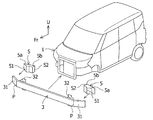
図1〜図5に示すように、本発明の実施形態に係る構造が適用される車両前部1には、主として、車両前後方向に沿って延び、車両両側部にそれぞれ配置されるサイドメンバ(フロントサイドメンバ)2と、車両幅方向に沿って延び、車両最先端の位置で直線的に配置されるとともに、車両後方側がサイドメンバ2に接合されるバンパメンバ3と、車両上下方向に延び、サイドメンバ2の先端部に取付けられるフロントサイドメンバエクステンション4とを有している。サイドメンバ2の前端部には、バンパメンバ3との接合部21が設けられ、バンパメンバ3の中間部分外側の車両後方側箇所には、サイドメンバ2との接合部32が設けられている。すなわち、サイドメンバ2とバンパメンバ3とは、左右両側の接合部21,32において接合されている。
本実施形態のバンパメンバ3は、車両幅方向の中間部分が直線的な構造であり、当該中間部分の車両幅方向外側に屈曲点(折れ点)Pを有している。しかも、バンパメンバ3の車両幅方向の両端には、車両幅方向外側に張り出し、屈曲点Pより車両後方へ向かって所定の後退角度θ(例えば、30°)で傾斜しながら所定の長さにわたり延びる張出部31がそれぞれ設けられている。屈曲点Pは、バンパメンバ3の前後幅と同等程度の距離で、サイドメンバ2との接合部32よりも車両外側に位置している。
As shown in FIGS. 1 to 5, the
The
本実施形態のバンパメンバ3における張出部31の車両幅方向内側には、図1、図2及び図4に示すように、左右両側のサイドメンバ2に向かってそれぞれ延びる突出部5が配設されており、これら突出部5は、平面視で略長方形状のボックス構造に形成されている。また、突出部5は、基端部5a側がバンパメンバ3の張出部31の内側壁面に取付けられて配設される配設部51と、先端部5b側がサイドメンバ2の車両外側の側面部2aに近接して配置され、かつ当該側面部2aに対向する平行な平面部52とを有している。これら突出部5の平面部52とフロントサイドメンバエクステンション4とは、車両前後方向で重なるように配置されている。しかも、突出部5の平面部52は、通常時、サイドメンバ2の車両外側の側面部2aとは接しておらず、平面部52と側面部2aとの間には隙間cが設けられている。この隙間cは、車両前部1の全面衝突時(フルラップ衝突時)に、バンパメンバ3の全体が車両後方に押し込まれた場合に、サイドメンバ2の変形が突出部5によって妨げられないようにするために、設けられたものである。車両前部1の全面衝突時は、バンパメンバ3の両端部に位置する張出部31に車両後方への折れ変形が発生せず、突出部5がサイドメンバ2の車両外側の側面部2aに当接しないからである。
As shown in FIGS. 1, 2 and 4, on the inside of the overhanging
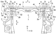
本実施形態の突出部5は、図2及び図4に示すように、張出部31への配設部51の後端部51aが突出部5の平面部52と重なるような形状に形成されており、当該配設部51の後端部51aは、車両側方視で、平面部52の車両前後方向の範囲内に収まるように配置されている。しかも、突出部5は、車両内側の平面部52の前後方向長さL1が車両外側の配設部51の前後方向長さL2よりも大きくなるように形成されている(L1>L2)。このような配置関係により、オフセット衝突時にバンパメンバ3の端部に位置する張出部31が折り込まれるように荷重を受け、車両内側横方向に荷重が掛かった場合に、当該横方向の荷重を突出部5の平面部52で受け、張出部31等の変形が止められるように構成されている。
As shown in FIGS. 2 and 4, the projecting
また、突出部5の車両前方側の内側面5cには、図2及び図4に示すように、車両後方側へ向かって屈曲する屈曲部53が設けられており、該屈曲部53は、車両外側の配設部51から車両内側の平面部52に渡って緩やかに湾曲した形状に形成されている。この屈曲部53が設けられていると、突出部5の先端部5b側に位置する平面部52の面積が広くとれるようになり、突出部5をコンパクトに設計した場合でも、サイドメンバ2の車両外側の側面部2aに対する平面部52の当接面積を十分確保することが可能となる。
さらに、突出部5の車両後方側の外側面5dは、バンパメンバ3の張出部31への配設部51の後端部51aから突出部5の平面部52へ向かって車両後方側に傾斜する直線状の平面に形成されている。このような形状に突出部5の車両後方側の外側面5dを形成することによって、オフセット衝突による斜め前方からの荷重に対し、突出部5の強度が高められ、突出部5によるバンパメンバ3の張出部31の変形が抑制されるように構成されている。
Further, as shown in FIGS. 2 and 4, a
Further, the
一方、突出部5の車両内側部分とバンパメンバ3の直線的な中間部分との間、及び突出部5の車両前方側と屈曲点Pの車両後方側との間には、図4に示すように、衝突時において、突出部5と周辺部品との干渉を避ける空間Sが設けられており、バンパメンバ3の張出部31からの衝撃荷重は、該空間Sによって突出部5と周辺部品とが干渉せず、突出部5を介してサイドメンバ2へ伝達されることが阻害されないようになっている。突出部5の車両内側部分とバンパメンバ3の直線的な中間部分との間隔は、バンパメンバ3の前後長さの約1/3の大きさに設定されている。
On the other hand, as shown in FIG. 4, between the vehicle inner side portion of the
本実施形態の車両前部1において、突出部5の平面部52とフロントサイドメンバエクステンション4とは、図4に示すように、車両前後方向で重なるように配置されている。そのため、突出部5の先端部5bの平面部52と対向する位置のサイドメンバ2がフロントサイドメンバエクステンション4によって補強されることになり、突出部5の平面部52がサイドメンバ2の側面部2aが当接するオフセット衝突時において、サイドメンバ2の車両内側への過度な変形が抑えられるように構成されている。
また、フロントサイドメンバエクステンション4は、図2〜図5に示すように、車両上部側で車両上方に延びているアッパエクステンション41と、車両下部側で車両下方に延びているロアエクステンション42とを有している。これらアッパエクステンション41及びロアエクステンション42は、開口部を車両内側に向けて配置した断面略コ字状に形成されており、アッパエクステンション41の下端部内にロアエクステンション42の上端部を配置した状態で接合されている。しかも、アッパエクステンション41は、サイドメンバ2の先端部上面に配置されて接合されており、ロアエクステンション42(フロントサイドメンバエクステンション4)の外側面とサイドメンバ2の車両内側の側面部2bとは、当接した状態で配置されている。すなわち、突出部5の平面部52が当接するサイドメンバ2の車両内側の箇所にフロントサイドメンバエクステンション4のロアエクステンション42が配置されることになるため、衝突時におけるサイドメンバ2の変形が起こり難くなり、バンパメンバ3の折れ曲がりが抑制されるようになっている。
In the
Further, as shown in FIGS. 2 to 5, the front
また、サイドメンバ2の上下に位置するフロントサイドメンバエクステンション4の箇所には、図2、図4及び図5に示すように、アッパエクステンション41及びロアエクステンション42が配置されている。これらアッパエクステンション41及びロアエクステンション42には、上下一対の取付ブラケット6,7が車両上下方向に間隔を空けて設けられており、バンパメンバ3の左右両端部は、上下一対の取付ブラケット6,7を介してアッパエクステンション41の下部及びロアエクステンション42の上部にそれぞれ取付けられている。そのため、上下一対の取付ブラケット6,7は、アッパエクステンション41及びロアエクステンション42の前面に固定される縦片6a,7aと、バンパメンバ3の車両幅方向の中間部分の両端後面に固定される横片6b,7bを有する断面L字状に形成されている。
すなわち、本実施形態の車両前部1は、バンパメンバ3をフロントサイドメンバエクステンション4のアッパエクステンション41及びロアエクステンション42に固定することにより、突出部5がサイドメンバ2に当接した際のオフセット衝突時の荷重などが、バンパメンバ3を介してフロントサイドメンバエクステンション4に分散されるようになっている。
Further, as shown in FIGS. 2, 4 and 5,
That is, in the
次に、本実施形態の車両前部構造において、車両前部1に対するオフセット衝突時の動作について説明する。
衝撃荷重がバンパメンバ3の片側端部に入力され、バンパメンバ3の端部に位置する張出部31が車両後方に押し込まれると、張出部31の内側に設けられた突出部5の車両内側の平面部52がサイドメンバ2の車両外側の側面部2aに当接する。それに伴い、バンパメンバ3の片側端部に入力された衝撃荷重は、突出部5を介してサイドメンバ2に伝達されるとともに、フロントサイドメンバエクステンション4にも分散される。そのため、バンパメンバ3の端部及びサイドメンバ2は、車室内へ向かって折れ込んだりすることなく、抑制された状態で変形することになる。一方、突出部5は、全体が変形することはなく、サイドメンバ2との当接箇所及びその周辺部分が変形するに過ぎない。
なお、車両前部1に対するフルラップ衝突時は、バンパメンバ3の左右両端部に位置する張出部31に車両後方への折れ変形が発生しない。しかも、突出部5の平面部52とサイドメンバ2との間に隙間cが存在するため、突出部5の平面部52がサイドメンバ2の車両外側の側面部2aに当接することなく、バンパメンバ3の車両幅方向の中間部分及びサイドメンバ2が車両後方へ向かって移動しながら変形することになる。
Next, in the vehicle front structure of the present embodiment, the operation at the time of an offset collision with the
When an impact load is input to one end of the
At the time of a full-wrap collision with the
このように、本発明の実施形態に係る車両前部構造は、車両前部1において車両前後方向に沿って延び、車両両側部にそれぞれ配置されるサイドメンバ2と、車両幅方向に沿って延び、車両最先端の位置で直線的に配置されるとともに、車両後方側がサイドメンバ2に接合されるバンパメンバ3と、車両上下方向に延び、サイドメンバ2の先端部に取付けられるフロントサイドメンバエクステンション4とを有している。バンパメンバ3は、車両幅方向外側に屈曲点Pを有し、車両幅方向の両端には、車両幅方向外側に張り出し、屈曲点Pより車両後方へ向かって傾斜しながら延びる張出部31が設けられている。しかも、張出部31の車両幅方向内側には、サイドメンバ2に向かって延びる突出部5が配設され、突出部5の車両内側の先端部5bは、サイドメンバ2の車両外側の側面部2aに対向する平面部52を有しており、突出部5の平面部52とフロントサイドメンバエクステンション4とは、車両前後方向で重なるように配置されている。
そのため、本発明の車両前部構造においては、車両前部1の片側端部が衝突する形態のオフセット衝突時に、衝突した側のバンパメンバ3の張出部31が車両後方に折り込まれると、突出部5がバンパメンバ3の変形に伴ってサイドメンバ2側へ向かって移動し、平面部52がサイドメンバ2の車両外側の側面部2aに当接することになる。したがって、本発明の構造によれば、突出部5がバンパメンバ3の張出部31とサイドメンバ2の側面部2aとの間に介在して支えとなり、バンパメンバ3の折れ変形などを抑えることができる。また、バンパメンバ3の変形が抑えられることによって、車室内へ向かうサイドメンバ2の変形を防止でき、被害を低減させることができる。さらに、本発明の車両前部構造においては、突出部5の平面部52に合わせてフロントサイドメンバエクステンション4がサイドメンバ2に設けられており、サイドメンバがフロントサイドメンバエクステンション4によって補強されているので、突出部5がサイドメンバ2に当接した時に、サイドメンバ2が車両内側へ変形し過ぎるのを防ぐことができるとともに、突出部5の有する機能が十分に得られることで、衝突時の被害軽減性能をより一層向上させることができる。
As described above, the vehicle front structure according to the embodiment of the present invention extends along the vehicle front-rear direction in the
Therefore, in the vehicle front structure of the present invention, when the overhanging
また、本実施形態の車両前部構造においては、バンパメンバ3の屈曲点Pがサイドメンバ2との接合部32よりも車両外側に位置しているので、バンパメンバ3の車両前後方向の長さを短くすることができ、車両のコンパクト化を実現することができる。しかも、本実施形態の構造では、車両前部1の衝突時に、サイドメンバ2によるバンパメンバ3の屈曲点Pでの変形が妨げられ難くなっているので、衝撃荷重の吸収効果を高めることができる。
Further, in the vehicle front structure of the present embodiment, since the bending point P of the
さらに、本実施形態の車両前部構造において、突出部5は、張出部31への配設部51の後端部51aが突出部5の平面部52と車両前後方向で重なるような形状に形成されているので、配設部51の後端部51aが、車両側方視で、平面部52の車両前後方向の範囲内に収まるようになっている。そのため、オフセット衝突によって、バンパメンバ3の端部に位置する張出部31が折り込まれるように荷重を受け、車両内側横方向に荷重が掛かった場合でも、当該横方向の荷重を突出部5の平面部52で受けることが可能となり、張出部31を有するバンパメンバ3の変形を確実に防止することができる。
Further, in the vehicle front structure of the present embodiment, the projecting
そして、本実施形態の車両前部構造では、突出部5の車両前方側の内側面5cに、車両後方側へ向かって屈曲する屈曲部53が設けられているので、突出部5の平面部52の面積を広く形成することができ、突出部5をコンパクトに設計しても、サイドメンバ2の側面部2aとの平面部52の十分な当接面積を確保でき、バンパメンバ3の変形を抑える突出部5の機能を安定して発揮させることができる。
Further, in the vehicle front structure of the present embodiment, since the
また、本実施形態の車両前部構造では、突出部5の車両後方側の外側面5dが、張出部31への配設部51の後端部51aから突出部5の平面部52へ向かって車両後方側に傾斜する直線状の平面に形成されているので、オフセット衝突による斜め前方からの荷重に対する突出部5の強度を増大させることができ、突出部5によるバンパメンバ3の張出部31の変形抑制効果を高めることができる。
Further, in the vehicle front structure of the present embodiment, the
さらに、本実施形態の車両前部構造では、フロントサイドメンバエクステンション4を構成するロアエクステンション42の外側面とサイドメンバ2の車両内側の側面部2bとが当接した状態で配置されているので、衝突時に発生するサイドメンバ2の変形を従来構造よりも起こり難くすることができ、バンパメンバ3の折れ曲がりを確実に防止できる。
Further, in the vehicle front structure of the present embodiment, the outer surface of the
そして、本実施形態の車両前部構造では、サイドメンバ2の上下に位置するフロントサイドメンバエクステンション4の箇所に、上下一対の取付ブラケット6,7が車両上下方向に間隔を空けて設けられ、バンパメンバ3の左右両端部は、上下一対の取付ブラケット6,7を介してフロントサイドメンバエクステンション4に取付けられているので、突出部4がサイドメンバ2に当接した際の荷重をバンパメンバ3を介してフロントサイドメンバエクステンション4に分散させることが可能となり、サイドメンバ2の変形を抑制でき、車室内への変形を効果的に低減させることができる。
In the vehicle front structure of the present embodiment, a pair of upper and lower mounting
以上、本発明の実施の形態につき述べたが、本発明は既述の実施の形態に限定されるものではなく、本発明の技術的思想に基づいて各種の変形及び変更が可能である。 Although the embodiments of the present invention have been described above, the present invention is not limited to the above-described embodiments, and various modifications and modifications can be made based on the technical idea of the present invention.
例えば、既述の実施の形態における突出部5は、ボックス構造に形成されているが、下側が開口した断面コ字形状に形成されていても良い。また、突出部5の内部は、空洞である必要はなく、剛性を高めるハニカム構造体等が充填された構造であってもいても良い。
For example, the
1 車両前部
2 サイドメンバ
2a 車両外側の側面部
2b 車両内側の側面部
3 バンパメンバ
4 フロントサイドメンバエクステンション
5 突出部
5a 基端部
5b 先端部
5c 内側面
5d 外側面
6,7 取付ブラケット
21 接合部
31 張出部
32 接合部
41 アッパエクステンション
42 ロアエクステンション
51 配設部
51a 後端部
52 平面部
53 屈曲部
c 隙間
P 屈曲点
S 空間
1
Claims (6)
前記バンパメンバは、車両幅方向外側に屈曲点を有し、前記バンパメンバの車両幅方向の両端には、車両幅方向外側に張り出し、前記屈曲点より車両後方へ向かって傾斜しながら延びる張出部が設けられている車両前部構造において、
前記張出部の車両幅方向内側には、前記サイドメンバに向かって延びる突出部が配設され、該突出部の車両内側の先端部は、前記サイドメンバの車両外側の側面部に対向する平面部を有しており、
前記突出部の平面部と前記フロントサイドメンバエクステンションとは、車両前後方向で重なるように配置され、
前記突出部は、前記張出部への配設部の後端部が前記突出部の平面部と車両前後方向で重なるような形状に形成されていることを特徴とする車両前部構造。 Side members that extend along the front-rear direction of the vehicle and are arranged on both sides of the vehicle, and side members that extend along the width direction of the vehicle and are arranged linearly at the most advanced position of the vehicle, and the rear side of the vehicle is joined to the side members. It has a bumper member to be mounted and a front side member extension extending in the vertical direction of the vehicle and attached to the tip of the side member.
The bumper member has bending points on the outer side in the vehicle width direction, and at both ends of the bumper member in the vehicle width direction, overhanging portions extending outward in the vehicle width direction and extending from the bending point toward the rear of the vehicle are provided. In the provided vehicle front structure,
A protrusion extending toward the side member is provided on the inside of the overhang in the vehicle width direction, and the tip of the protrusion on the inside of the vehicle is a flat surface facing the side surface of the side member on the outside of the vehicle. Has a part
The flat surface portion of the protruding portion and the front side member extension are arranged so as to overlap each other in the front-rear direction of the vehicle .
The vehicle front structure is characterized in that the protruding portion is formed so that the rear end portion of the portion disposed on the overhanging portion overlaps the flat surface portion of the protruding portion in the vehicle front-rear direction.
前記バンパメンバは、車両幅方向外側に屈曲点を有し、前記バンパメンバの車両幅方向の両端には、車両幅方向外側に張り出し、前記屈曲点より車両後方へ向かって傾斜しながら延びる張出部が設けられている車両前部構造において、
前記張出部の車両幅方向内側には、前記サイドメンバに向かって延びる突出部が配設され、該突出部の車両内側の先端部は、前記サイドメンバの車両外側の側面部に対向する平面部を有しており、
前記突出部の平面部と前記フロントサイドメンバエクステンションとは、車両前後方向で重なるように配置され、
前記突出部の車両後方側の外側面は、前記張出部への配設部の後端部から前記突出部の平面部へ向かって車両後方側に傾斜する直線状の平面に形成されていることを特徴とする車両前部構造。 Side members that extend along the front-rear direction of the vehicle and are arranged on both sides of the vehicle, and side members that extend along the width direction of the vehicle and are arranged linearly at the most advanced position of the vehicle, and the rear side of the vehicle is joined to the side members. It has a bumper member to be mounted and a front side member extension extending in the vertical direction of the vehicle and attached to the tip of the side member.
The bumper member has bending points on the outer side in the vehicle width direction, and at both ends of the bumper member in the vehicle width direction, overhanging portions extending outward in the vehicle width direction and extending from the bending point toward the rear of the vehicle are provided. In the provided vehicle front structure,
A protrusion extending toward the side member is provided on the inside of the overhang in the vehicle width direction, and the tip of the protrusion on the inside of the vehicle is a flat surface facing the side surface of the side member on the outside of the vehicle. Has a part
The flat surface portion of the protruding portion and the front side member extension are arranged so as to overlap each other in the front-rear direction of the vehicle.
The outer surface of the projecting portion on the rear side of the vehicle is formed in a linear plane that is inclined toward the rear side of the vehicle from the rear end portion of the disposition portion on the overhanging portion toward the flat surface portion of the projecting portion. car both front structure, characterized in that there.
前記バンパメンバは、車両幅方向外側に屈曲点を有し、前記バンパメンバの車両幅方向の両端には、車両幅方向外側に張り出し、前記屈曲点より車両後方へ向かって傾斜しながら延びる張出部が設けられている車両前部構造において、
前記張出部の車両幅方向内側には、前記サイドメンバに向かって延びる突出部が配設され、該突出部の車両内側の先端部は、前記サイドメンバの車両外側の側面部に対向する平面部を有しており、
前記突出部の平面部と前記フロントサイドメンバエクステンションとは、車両前後方向で重なるように配置され、
前記サイドメンバの上下に位置する前記フロントサイドメンバエクステンションの箇所には、上下一対の取付ブラケットが車両上下方向に間隔を空けて設けられ、前記バンパメンバは、前記上下一対の取付ブラケットを介して前記フロントサイドメンバエクステンションに取付けられていることを特徴とする車両前部構造。 Side members that extend along the front-rear direction of the vehicle and are arranged on both sides of the vehicle, and side members that extend along the width direction of the vehicle and are arranged linearly at the most advanced position of the vehicle, and the rear side of the vehicle is joined to the side members. It has a bumper member to be mounted and a front side member extension extending in the vertical direction of the vehicle and attached to the tip of the side member.
The bumper member has bending points on the outer side in the vehicle width direction, and at both ends of the bumper member in the vehicle width direction, overhanging portions extending outward in the vehicle width direction and extending from the bending point toward the rear of the vehicle are provided. In the provided vehicle front structure,
A protrusion extending toward the side member is provided on the inside of the overhang in the vehicle width direction, and the tip of the protrusion on the inside of the vehicle is a flat surface facing the side surface of the side member on the outside of the vehicle. Has a part
The flat surface portion of the protruding portion and the front side member extension are arranged so as to overlap each other in the front-rear direction of the vehicle.
A pair of upper and lower mounting brackets are provided at positions of the front side member extensions located above and below the side member at intervals in the vertical direction of the vehicle, and the bumper member is provided on the front via the pair of upper and lower mounting brackets. car both front structure, characterized by being mounted et the side member extension.
Priority Applications (5)
| Application Number | Priority Date | Filing Date | Title |
|---|---|---|---|
| JP2017082970A JP6863036B2 (en) | 2017-04-19 | 2017-04-19 | Vehicle front structure |
| DE102018104834.3A DE102018104834A1 (en) | 2017-04-19 | 2018-03-02 | VEHICLE FRONT STRUCTURE |
| CN201810298269.0A CN108725589B (en) | 2017-04-19 | 2018-04-04 | Vehicle front structure |
| FR1853118A FR3065416B1 (en) | 2017-04-19 | 2018-04-10 | VEHICLE FRONT STRUCTURE COMPRISING A BUMPER WITH A PROTUBERANCE ARRANGED TO DEFORM DURING A DECALED IMPACT |
| US15/952,775 US10494029B2 (en) | 2017-04-19 | 2018-04-13 | Vehicle front structure |
Applications Claiming Priority (1)
| Application Number | Priority Date | Filing Date | Title |
|---|---|---|---|
| JP2017082970A JP6863036B2 (en) | 2017-04-19 | 2017-04-19 | Vehicle front structure |
Publications (2)
| Publication Number | Publication Date |
|---|---|
| JP2018177124A JP2018177124A (en) | 2018-11-15 |
| JP6863036B2 true JP6863036B2 (en) | 2021-04-21 |
Family
ID=63714291
Family Applications (1)
| Application Number | Title | Priority Date | Filing Date |
|---|---|---|---|
| JP2017082970A Active JP6863036B2 (en) | 2017-04-19 | 2017-04-19 | Vehicle front structure |
Country Status (5)
| Country | Link |
|---|---|
| US (1) | US10494029B2 (en) |
| JP (1) | JP6863036B2 (en) |
| CN (1) | CN108725589B (en) |
| DE (1) | DE102018104834A1 (en) |
| FR (1) | FR3065416B1 (en) |
Families Citing this family (3)
| Publication number | Priority date | Publication date | Assignee | Title |
|---|---|---|---|---|
| US10661833B2 (en) | 2018-06-29 | 2020-05-26 | Nissan North America, Inc. | Vehicle body structure |
| CN109835417B (en) * | 2019-02-22 | 2021-05-04 | 重庆长安汽车股份有限公司 | Vehicle body supporting structure |
| JP7115414B2 (en) * | 2019-05-08 | 2022-08-09 | トヨタ自動車株式会社 | vehicle front structure |
Family Cites Families (14)
| Publication number | Priority date | Publication date | Assignee | Title |
|---|---|---|---|---|
| JP4122887B2 (en) * | 2002-08-05 | 2008-07-23 | 日産自動車株式会社 | Body front structure |
| EP2330018B1 (en) * | 2008-10-02 | 2012-12-26 | Honda Motor Co., Ltd. | Structure for vehicle body front portion |
| JP2012228897A (en) * | 2011-04-25 | 2012-11-22 | Nitto Denko Corp | Bumper support member, bumper support structure, and vehicle |
| US8454080B2 (en) * | 2011-09-19 | 2013-06-04 | Ford Global Technologies, Llc | Bumper beam with load transferring section |
| DE112012006244T5 (en) * | 2012-04-19 | 2015-03-05 | Toyota Jidosha Kabushiki Kaisha | Structure for the front part of a vehicle body |
| EP2851272B1 (en) * | 2012-05-18 | 2016-10-05 | Nissan Motor Co., Ltd. | Structure for front part of vehicle body |
| DE102012023674A1 (en) * | 2012-11-28 | 2014-05-28 | GM Global Technology Operations LLC (n. d. Ges. d. Staates Delaware) | Motor vehicle with modular bodywork |
| JP2015058793A (en) * | 2013-09-18 | 2015-03-30 | トヨタ自動車株式会社 | Vehicle body front part structure |
| GB2519810A (en) * | 2013-10-31 | 2015-05-06 | Gm Global Tech Operations Inc | Vehicle front structure |
| JP6044794B2 (en) * | 2014-06-19 | 2016-12-14 | マツダ株式会社 | Front body structure of the vehicle |
| JP2016037074A (en) * | 2014-08-05 | 2016-03-22 | トヨタ自動車株式会社 | Vehicle front structure |
| JP2016078492A (en) | 2014-10-10 | 2016-05-16 | トヨタ自動車東日本株式会社 | Vehicle front part structure |
| JP2019001391A (en) * | 2017-06-19 | 2019-01-10 | スズキ株式会社 | Vehicle front structure |
| FR3070665B1 (en) * | 2017-09-07 | 2019-09-13 | Compagnie Plastic Omnium | MONOBLOCK PIECE FORMING A FRONT BLOCK COMPRISING AN ABSORPTION SYSTEM AND AERODYNAMIC SYSTEM |
-
2017
- 2017-04-19 JP JP2017082970A patent/JP6863036B2/en active Active
-
2018
- 2018-03-02 DE DE102018104834.3A patent/DE102018104834A1/en active Pending
- 2018-04-04 CN CN201810298269.0A patent/CN108725589B/en active Active
- 2018-04-10 FR FR1853118A patent/FR3065416B1/en active Active
- 2018-04-13 US US15/952,775 patent/US10494029B2/en active Active
Also Published As
| Publication number | Publication date |
|---|---|
| CN108725589B (en) | 2020-07-21 |
| CN108725589A (en) | 2018-11-02 |
| FR3065416A1 (en) | 2018-10-26 |
| DE102018104834A1 (en) | 2018-10-25 |
| US20180304930A1 (en) | 2018-10-25 |
| FR3065416B1 (en) | 2022-04-29 |
| US10494029B2 (en) | 2019-12-03 |
| JP2018177124A (en) | 2018-11-15 |
Similar Documents
| Publication | Publication Date | Title |
|---|---|---|
| JP5924308B2 (en) | Body front structure | |
| JP5360556B2 (en) | Automotive bumper structure | |
| CN109131574B (en) | Vehicle front structure | |
| JP6863036B2 (en) | Vehicle front structure | |
| EP1726490A1 (en) | Vehicle body front part structure of automobile | |
| US20130175827A1 (en) | Hood inner panel | |
| JP5994321B2 (en) | Body front structure | |
| US7472948B2 (en) | Vehicle body structure | |
| JP6020203B2 (en) | Body front structure | |
| JP6237290B2 (en) | Body front structure | |
| JP2007131150A (en) | Front bumper structure of vehicle | |
| JP2022036512A (en) | Vehicle body front part structure | |
| JP5383359B2 (en) | Front body structure of automobile | |
| JP5092319B2 (en) | Vehicle front-rear direction end structure | |
| JP6801502B2 (en) | Front hood for vehicles | |
| JP6776871B2 (en) | Vehicle front structure | |
| JP2005104264A (en) | Car body front part structure | |
| JP7040082B2 (en) | Vampari Information | |
| JP7067254B2 (en) | Body front structure | |
| JP7338647B2 (en) | Underrun protector fixing structure | |
| WO2020179824A1 (en) | Bumper | |
| JP7202240B2 (en) | vehicle front structure | |
| JP2011110991A (en) | Vehicular front structure | |
| WO2023100341A1 (en) | Front structure of body frame | |
| JP2008074264A (en) | Front part vehicle body structure for vehicle |
Legal Events
| Date | Code | Title | Description |
|---|---|---|---|
| A621 | Written request for application examination |
Free format text: JAPANESE INTERMEDIATE CODE: A621 Effective date: 20200306 |
|
| A977 | Report on retrieval |
Free format text: JAPANESE INTERMEDIATE CODE: A971007 Effective date: 20201117 |
|
| A131 | Notification of reasons for refusal |
Free format text: JAPANESE INTERMEDIATE CODE: A131 Effective date: 20201201 |
|
| A521 | Request for written amendment filed |
Free format text: JAPANESE INTERMEDIATE CODE: A523 Effective date: 20210201 |
|
| TRDD | Decision of grant or rejection written | ||
| A01 | Written decision to grant a patent or to grant a registration (utility model) |
Free format text: JAPANESE INTERMEDIATE CODE: A01 Effective date: 20210302 |
|
| A61 | First payment of annual fees (during grant procedure) |
Free format text: JAPANESE INTERMEDIATE CODE: A61 Effective date: 20210315 |
|
| R151 | Written notification of patent or utility model registration |
Ref document number: 6863036 Country of ref document: JP Free format text: JAPANESE INTERMEDIATE CODE: R151 |