EP1726490A1 - Vehicle body front part structure of automobile - Google Patents
Vehicle body front part structure of automobile Download PDFInfo
- Publication number
- EP1726490A1 EP1726490A1 EP06252712A EP06252712A EP1726490A1 EP 1726490 A1 EP1726490 A1 EP 1726490A1 EP 06252712 A EP06252712 A EP 06252712A EP 06252712 A EP06252712 A EP 06252712A EP 1726490 A1 EP1726490 A1 EP 1726490A1
- Authority
- EP
- European Patent Office
- Prior art keywords
- leg
- vehicle body
- leg sweeping
- front bumper
- automobile
- Prior art date
- Legal status (The legal status is an assumption and is not a legal conclusion. Google has not performed a legal analysis and makes no representation as to the accuracy of the status listed.)
- Granted
Links
Images


Classifications
-
- B—PERFORMING OPERATIONS; TRANSPORTING
- B60—VEHICLES IN GENERAL
- B60R—VEHICLES, VEHICLE FITTINGS, OR VEHICLE PARTS, NOT OTHERWISE PROVIDED FOR
- B60R19/00—Wheel guards; Radiator guards, e.g. grilles; Obstruction removers; Fittings damping bouncing force in collisions
- B60R19/02—Bumpers, i.e. impact receiving or absorbing members for protecting vehicles or fending off blows from other vehicles or objects
- B60R19/24—Arrangements for mounting bumpers on vehicles
- B60R19/26—Arrangements for mounting bumpers on vehicles comprising yieldable mounting means
- B60R19/34—Arrangements for mounting bumpers on vehicles comprising yieldable mounting means destroyed upon impact, e.g. one-shot type
-
- B—PERFORMING OPERATIONS; TRANSPORTING
- B60—VEHICLES IN GENERAL
- B60R—VEHICLES, VEHICLE FITTINGS, OR VEHICLE PARTS, NOT OTHERWISE PROVIDED FOR
- B60R19/00—Wheel guards; Radiator guards, e.g. grilles; Obstruction removers; Fittings damping bouncing force in collisions
- B60R19/02—Bumpers, i.e. impact receiving or absorbing members for protecting vehicles or fending off blows from other vehicles or objects
- B60R19/24—Arrangements for mounting bumpers on vehicles
- B60R2019/247—Fastening of bumpers' side ends
-
- B—PERFORMING OPERATIONS; TRANSPORTING
- B60—VEHICLES IN GENERAL
- B60R—VEHICLES, VEHICLE FITTINGS, OR VEHICLE PARTS, NOT OTHERWISE PROVIDED FOR
- B60R21/00—Arrangements or fittings on vehicles for protecting or preventing injuries to occupants or pedestrians in case of accidents or other traffic risks
- B60R21/34—Protecting non-occupants of a vehicle, e.g. pedestrians
Landscapes
- Engineering & Computer Science (AREA)
- Mechanical Engineering (AREA)
- Body Structure For Vehicles (AREA)
Abstract
Description
- The present invention relates to a vehicle body front part structure of an automobile, comprising leg sweeping plates connected to a vehicle body at lower portions of left and right bent parts of a front bumper.
-
Japanese Patent Application Laid-open No. 2001-88634 - The above described conventional structure does not include a construction which reliably buckles the projecting member (leg sweeping plate) when the front bumper lightly collides with another automobile or the like. Therefore, there is a possibility that the vehicle body supporting the projecting member (leg sweeping plate) deforms to enlarge the damage. In addition, there is also a problem of increasing the weight and cost because the projecting member (leg sweeping plate) is disposed over the substantially entire length of the front bumper.
- The present invention has been achieved in view of the above circumstances, and has an obj ect to make a leg sweeping plate compact and light, and reduce damage to a vehicle body as much as possible when colliding with another automobile while securing its leg sweeping function.
- According to a first feature of the present invention, there is provided a vehicle body front part structure of an automobile, comprising leg sweeping plates connected to a vehicle body at lower portions of left and right bent parts of a front bumper, characterized in that each of the leg sweeping plates has an energy absorbing portion that deforms when collision energy at the time of a light collision exceeds a predetermined value, thereby preventing deformation of the vehicle body.
- With the arrangement of the first feature of the present invention, each of the leg sweeping plates provided at the lower portions of the left and right bent parts of the front bumper has the energy absorbing portion that deforms when collision energy inputted into the front bumper at the time of a light collision exceeds a predetermined value, thereby preventing deformation of the vehicle body. Therefore, when the front bumper collides with a pedestrian, the collision energy is at the predetermined value or less, and the leg sweeping plates do not deform, but sweep the leg portions under the knees of the pedestrian to throw up the pedestrian onto the bonnet, thereby reducing the impact of the collision. Also, when the automobile lightly collides with another automobile or the like and the collision energy exceeds the predetermined value, the leg sweeping plates deform at the energy absorbing portions, and therefore the leg sweeping plates absorb the collision energy at the energy absorbing portions, thereby avoiding damage to the vehicle body. Further, the leg sweeping plates are provided at only the left and right bent parts of the front bumper, and therefore the leg sweeping plates are light and inexpensive as compared with the case of the leg sweeping plate provided over the entire front bumper.
- According to a second feature of the present invention, in addition to the first feature, the energy absorbing portion of each of the leg sweeping plates is formed into a shape of a plica whose ridges extending in a lateral direction of the vehicle body.
- With the arrangement of the second feature of the present invention, when a large compression load acts on each of the leg sweeping plates in the longitudinal direction of the vehicle body, the energy absorbing portion formed into the shape of a plica whose ridges extending in the lateral direction of the vehicle body is reliably deformed, thereby avoiding a damage to the vehicle body.
- According to a third feature of the present invention, in addition to the second feature, each of the leg sweeping plates has a plurality of reinforcing ribs extending in a longitudinal direction of the vehicle body in front of the energy absorbing portion.
- With the arrangement of the third feature of the present invention, when a large compression load acts on each of the leg sweeping plates in the longitudinal direction of the vehicle body, because the front portion of the leg sweeping plate is enhanced in rigidity by the reinforcing ribs, the energy absorbing portion in the rear of the reinforcing ribs is further reliably deformed.
- The above-mentioned object, other objects, characteristics, and advantages of the present invention will become apparent from a preferred embodiment, which will be described in detail below by reference to the attached drawings, in which:
- FIG. 1 is a perspective view of a vehicle body front part of an automobile;
- FIG. 2 is a view taken in the direction of the
arrow 2 in FIG. 1; - FIG. 3 is an enlarged view of the
part 3 in FIG. 2; - FIG. 4 is a sectional view taken along the line 4-4 in FIG. 3;
- FIG. 5 is a perspective view of a leg sweeping plate; and
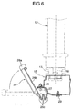
- FIG. 6 is an explanatory view of an operation at the time of light collision.
- FIGS. 1 to 6 show one embodiment of the present invention.
- As shown in FIGS. 1 to 4, a
radiator 12 is supported at a center of abulkhead 11 disposed at a front part of a vehicle body of an automobile. External air is taken in through an unillustrated opening formed in a front surface of afront bumper 13 disposed on a front surface of thebulkhead 11, and is guided to theradiator 12. Thebulkhead 11 is constructed into a frame shape by a bulkheadupper part 14, a bulkheadlower part 15 and left andright bulkhead sides radiator 12 are supported byfitting support pins rubber bushes lower part 15. Opposite ends of an upper portion of theradiator 12 are fixed to the bulkheadupper part 14 via unillustrated brackets. - Bent
parts front bumper 13, which extend in a lateral direction of the vehicle body, toward the portions extending in a longitudinal direction of the vehicle body, and are supported by the left andright bulkhead sides brackets sweeping plates lower part 15 and which correspond to lower portions of the left andright bent portions front bumper 13. - As is obvious from FIG. 5, the leg
sweeping plate 26 is made by press-forming a metal plate, and itsfront edge portion 26a abutting on a back surface of abumper face 19 is bent back into a J-shape. A plurality of reinforcingribs 26b extending in the longitudinal direction of the vehicle body are formed at the rear side of thefront edge portion 26a. Anenergy absorbing portion 26c having a shape of a plica whose ridges extend in the lateral direction of the vehicle body is formed in the rear of the reinforcingribs 26b. Abolt hole 26d is formed at an inner end in the vehicle width direction of theenergy absorbing portion 26c. Abolt 27, which penetrates through thebolt hole 26d, penetrates through a front edge of the bulkheadlower part 15 and is fastened to anut 28. Aclip hole 26e is formed in a rear edge of the legsweeping plate 26 at a position near an outer end in the vehicle width direction. Aclip 29 penetrating through theclip hole 26e is fixed to the front edge of the bulkheadlower part 15. - Accordingly, when the
front bumper 13 of the automobile collides with a pedestrian, thefront bumper 13 sweeps the leg portions under the knees of the pedestrian to throw up the pedestrian onto the bonnet, thereby reducing the impact of the collision. At this time, if thefront bumper 13 is easily buckled, the pedestrian cannot be successfully thrown up onto the bonnet, but in this embodiment, a pair of left and right legsweeping plates front bumper 13 and thebulkhead 11, and therefore, the rigidity of the lower portion of thefront bumper 13 is appropriately enhanced to thereby effectively sweep the leg portions under the knees of the pedestrian. The rigidity in the longitudinal direction of the legsweeping plate 26 can be especially enhanced by the reinforcingribs 26b. - When the automobile lightly collides with another automobile or a fixed object, if the rigidity of the leg
sweeping plates bulkhead 11 to which the legsweeping plates bulkhead 11. However, according to this embodiment, when a compression load acts on each of the legsweeping plates 26 in the longitudinal direction of the vehicle body by a light collision with thefront bumper 13, theenergy absorbing portion 26c at the rear sides of the reinforcingribs 26b is easily deformed to be bent as shown in FIG. 6, because the front portion of the legsweeping plate 26 is enhanced in rigidity by the reinforcingribs 26b, whereby thebulkhead 11 and the front side frame can be prevented from being damaged by the impact of the collision. - When the
front bumper 13 strongly collides with a pedestrian, the legsweeping plates energy absorbing portions - As described above, the
energy absorbing portions sweeping plates front bumper 13 at thebulkhead 11. Therefore, when colliding with a pedestrian, the pedestrian is reliably thrown up onto the bonnet by suppressing buckling of thefront bumper 13 with the legsweeping plates sweeping plates 2 6 and 2 6 are deformed at theenergy absorbing portions 2 6c and 26c to avoiddamage to thebulkhead 11. In addition, the legsweeping plates right bent parts front bumper 13, and therefore, the legsweeping plates front bumper 13. - Further, when a vehicle body on which a
front bumper 13 has not been mounted, is transported on an overhead conveyor, the legsweeping plates 26 position at the height of the face of an operator, but there is no fear of hurting the face of the operator because thefront edge portions 26a are bent back into the J-shape. - The embodiment of the present invention has been described above, but the present invention is not limited to the above described embodiment, and various design changes can be made without departing from the present invention described in the claims.
- For example, if the strength of the
clip 29 fixing the legsweeping plate 26 to the bulkheadlower part 15 is set so that theclip 29 breaks at the time of a light collision, theclip 29 breaks and the legsweeping plate 26 rotates around thebolt 27 upon collision, thereby making it more difficult for the impact of the collision to be transmitted to thebulkhead 11.
Claims (3)
- A vehicle body front part structure of an automobile, comprising leg sweeping plates (26) connected to a vehicle body at lower portions of left and right bent parts (13a) of a front bumper (13),
characterized in that each of the leg sweeping plates (26) has an energy absorbing portion (26c) that deforms when collision energy at the time of a light collision exceeds a predetermined value, thereby preventing deformation of the vehicle body. - A vehicle body front part structure of an automobile, according to claim 1, characterized in that the energy absorbing portion (26c) of each of the leg sweeping plates (26) is formed into a shape of a plica whose ridges extending in a lateral direction of the vehicle body.
- A vehicle body front part structure of an automobile, according to claim 1 or 2, characterized in that each of the leg sweeping plates (26) has a plurality of reinforcing ribs (26b) extending in a longitudinal direction of the vehicle body in front of the energy absorbing portion (26c).
Applications Claiming Priority (1)
| Application Number | Priority Date | Filing Date | Title |
|---|---|---|---|
| JP2005154826A JP4271164B2 (en) | 2005-05-27 | 2005-05-27 | Front body structure of automobile |
Publications (2)
| Publication Number | Publication Date |
|---|---|
| EP1726490A1 true EP1726490A1 (en) | 2006-11-29 |
| EP1726490B1 EP1726490B1 (en) | 2009-02-11 |
Family
ID=36968663
Family Applications (1)
| Application Number | Title | Priority Date | Filing Date |
|---|---|---|---|
| EP06252712A Expired - Fee Related EP1726490B1 (en) | 2005-05-27 | 2006-05-24 | Vehicle body front part structure of automobile |
Country Status (4)
| Country | Link |
|---|---|
| EP (1) | EP1726490B1 (en) |
| JP (1) | JP4271164B2 (en) |
| CN (1) | CN100434310C (en) |
| DE (1) | DE602006005097D1 (en) |
Cited By (5)
| Publication number | Priority date | Publication date | Assignee | Title |
|---|---|---|---|---|
| US7575271B2 (en) | 2006-06-13 | 2009-08-18 | Kojima Press Industry Co., Ltd. | Pedestrian protection apparatus for vehicle |
| FR2940215A1 (en) * | 2008-12-22 | 2010-06-25 | Valeo Systemes Thermiques | Beam support and pedestrian beam assembly for use in front panel for supporting equipments e.g. headlamp, of vehicle motor vehicle, has support that is in contact with pedestrian beam to absorb part of energy released during impact |
| FR2940210A1 (en) * | 2008-12-22 | 2010-06-25 | Valeo Systemes Thermiques | Beam support and pedestrian beam assembly for use in front face of motor vehicle, has pedestrian beam formed with two distinct parts comprising two distal ends separated from each other so that distinct parts are separated at distance |
| US9327675B2 (en) | 2013-08-21 | 2016-05-03 | Mazda Motor Corporation | Vehicle-body front structure of vehicle |
| GB2532577A (en) * | 2014-10-29 | 2016-05-25 | Gm Global Tech Operations Llc | Front part of a motor vehicle and stiffening thereto |
Families Citing this family (7)
| Publication number | Priority date | Publication date | Assignee | Title |
|---|---|---|---|---|
| JP4479637B2 (en) * | 2005-09-28 | 2010-06-09 | トヨタ自動車株式会社 | Bumper structure for vehicles |
| JP5097809B2 (en) * | 2010-08-31 | 2012-12-12 | 本田技研工業株式会社 | Lower duct structure for vehicle |
| JP5767842B2 (en) * | 2011-03-31 | 2015-08-19 | 本田技研工業株式会社 | Body front structure |
| CN104210560A (en) * | 2014-08-30 | 2014-12-17 | 常州市盛发灯泡厂 | Comprehensive sand-gravel barrier |
| US9616836B2 (en) * | 2015-01-26 | 2017-04-11 | Ford Global Technologies, Llc | Two dimensional pedestrian impact sensing |
| JP6514732B2 (en) * | 2017-04-28 | 2019-05-15 | トヨタ自動車東日本株式会社 | Pedestrian protection structure at the front of the vehicle |
| JP6844489B2 (en) * | 2017-10-03 | 2021-03-17 | トヨタ自動車株式会社 | Vehicle front structure |
Citations (2)
| Publication number | Priority date | Publication date | Assignee | Title |
|---|---|---|---|---|
| EP1273483A2 (en) * | 2001-07-05 | 2003-01-08 | Dynamit Nobel Kunststoff GmbH | Bumper support for improved pedestrian protection on motor vehicles |
| EP1459941A1 (en) * | 2003-03-20 | 2004-09-22 | Compagnie Plastic Omnium | Batch of at least two lower support for bumper of a vehicle and batch of two front blocks |
Family Cites Families (2)
| Publication number | Priority date | Publication date | Assignee | Title |
|---|---|---|---|---|
| JP2001088634A (en) * | 1999-09-28 | 2001-04-03 | Mazda Motor Corp | Front body structure of vehicle |
| US6406081B1 (en) * | 2001-03-20 | 2002-06-18 | General Electric Company | Energy absorber system |
-
2005
- 2005-05-27 JP JP2005154826A patent/JP4271164B2/en not_active Expired - Fee Related
-
2006
- 2006-05-24 DE DE602006005097T patent/DE602006005097D1/en active Active
- 2006-05-24 EP EP06252712A patent/EP1726490B1/en not_active Expired - Fee Related
- 2006-05-26 CN CNB2006100846631A patent/CN100434310C/en active Active
Patent Citations (2)
| Publication number | Priority date | Publication date | Assignee | Title |
|---|---|---|---|---|
| EP1273483A2 (en) * | 2001-07-05 | 2003-01-08 | Dynamit Nobel Kunststoff GmbH | Bumper support for improved pedestrian protection on motor vehicles |
| EP1459941A1 (en) * | 2003-03-20 | 2004-09-22 | Compagnie Plastic Omnium | Batch of at least two lower support for bumper of a vehicle and batch of two front blocks |
Cited By (6)
| Publication number | Priority date | Publication date | Assignee | Title |
|---|---|---|---|---|
| US7575271B2 (en) | 2006-06-13 | 2009-08-18 | Kojima Press Industry Co., Ltd. | Pedestrian protection apparatus for vehicle |
| EP1867526A3 (en) * | 2006-06-13 | 2009-12-02 | Kojima Press Industry Co., Ltd. | Pedestrian protection apparatus for vehicle |
| FR2940215A1 (en) * | 2008-12-22 | 2010-06-25 | Valeo Systemes Thermiques | Beam support and pedestrian beam assembly for use in front panel for supporting equipments e.g. headlamp, of vehicle motor vehicle, has support that is in contact with pedestrian beam to absorb part of energy released during impact |
| FR2940210A1 (en) * | 2008-12-22 | 2010-06-25 | Valeo Systemes Thermiques | Beam support and pedestrian beam assembly for use in front face of motor vehicle, has pedestrian beam formed with two distinct parts comprising two distal ends separated from each other so that distinct parts are separated at distance |
| US9327675B2 (en) | 2013-08-21 | 2016-05-03 | Mazda Motor Corporation | Vehicle-body front structure of vehicle |
| GB2532577A (en) * | 2014-10-29 | 2016-05-25 | Gm Global Tech Operations Llc | Front part of a motor vehicle and stiffening thereto |
Also Published As
| Publication number | Publication date |
|---|---|
| JP2006327438A (en) | 2006-12-07 |
| DE602006005097D1 (en) | 2009-03-26 |
| CN100434310C (en) | 2008-11-19 |
| CN1868786A (en) | 2006-11-29 |
| JP4271164B2 (en) | 2009-06-03 |
| EP1726490B1 (en) | 2009-02-11 |
Similar Documents
| Publication | Publication Date | Title |
|---|---|---|
| EP1726490A1 (en) | Vehicle body front part structure of automobile | |
| EP1972506A1 (en) | Underrun protector mounting structure of vehicle | |
| US10596994B2 (en) | Front structure of vehicle | |
| US7597384B2 (en) | Engine compartment hood latch structure for a motor vehicle | |
| US9327675B2 (en) | Vehicle-body front structure of vehicle | |
| RU116827U1 (en) | VEHICLE STAND WITH HOLE HAVING AN EXTENDED CORNER EDGE (OPTIONS) | |
| JP2005306161A (en) | Bumper device | |
| JP2007283868A (en) | Bumper mounting part structure | |
| US7703829B2 (en) | Instrument panel energy transferring system | |
| CN108001210B (en) | Collapsible radiator support brace for pedestrian safety | |
| JP2004203158A (en) | Front part structure of automobile | |
| CN109941215B (en) | Protective upper part for vehicle | |
| US7651157B2 (en) | Safety device | |
| JP6863036B2 (en) | Vehicle front structure | |
| JP2007168594A (en) | Pedestrian protection device for vehicle | |
| EP1277630A1 (en) | Front hood device | |
| JP6514732B2 (en) | Pedestrian protection structure at the front of the vehicle | |
| CN111479724A (en) | Impact absorbing structure for vehicle | |
| JP6444824B2 (en) | Bumper absorber | |
| JP6566018B2 (en) | Vehicle shock absorption structure | |
| US20050225102A1 (en) | Bumper device for a vehicle | |
| JP6710229B2 (en) | Mounting member | |
| JP6558384B2 (en) | Vehicle front structure | |
| US11673522B2 (en) | Vehicle front bumper and vehicle-body structure including the same | |
| JP4477978B2 (en) | Reinforcing member mounting structure for securing a living space in the event of a collision |
Legal Events
| Date | Code | Title | Description |
|---|---|---|---|
| PUAI | Public reference made under article 153(3) epc to a published international application that has entered the european phase |
Free format text: ORIGINAL CODE: 0009012 |
|
| AK | Designated contracting states |
Kind code of ref document: A1 Designated state(s): AT BE BG CH CY CZ DE DK EE ES FI FR GB GR HU IE IS IT LI LT LU LV MC NL PL PT RO SE SI SK TR |
|
| AX | Request for extension of the european patent |
Extension state: AL BA HR MK YU |
|
| 17P | Request for examination filed |
Effective date: 20070416 |
|
| 17Q | First examination report despatched |
Effective date: 20070518 |
|
| AKX | Designation fees paid |
Designated state(s): DE GB |
|
| GRAP | Despatch of communication of intention to grant a patent |
Free format text: ORIGINAL CODE: EPIDOSNIGR1 |
|
| RIN1 | Information on inventor provided before grant (corrected) |
Inventor name: OKABE, KOJIROC/O HONDA R&D CO., LTD. Inventor name: MORINO, TETSUYAC/O HONDA R&D CO., LTD. Inventor name: ISHIZONO, MANABUC/O HONDA R&D CO., LTD. |
|
| GRAS | Grant fee paid |
Free format text: ORIGINAL CODE: EPIDOSNIGR3 |
|
| GRAA | (expected) grant |
Free format text: ORIGINAL CODE: 0009210 |
|
| AK | Designated contracting states |
Kind code of ref document: B1 Designated state(s): DE GB |
|
| REG | Reference to a national code |
Ref country code: GB Ref legal event code: FG4D |
|
| REF | Corresponds to: |
Ref document number: 602006005097 Country of ref document: DE Date of ref document: 20090326 Kind code of ref document: P |
|
| PLBE | No opposition filed within time limit |
Free format text: ORIGINAL CODE: 0009261 |
|
| STAA | Information on the status of an ep patent application or granted ep patent |
Free format text: STATUS: NO OPPOSITION FILED WITHIN TIME LIMIT |
|
| 26N | No opposition filed |
Effective date: 20091112 |
|
| REG | Reference to a national code |
Ref country code: DE Ref legal event code: R084 Ref document number: 602006005097 Country of ref document: DE |
|
| REG | Reference to a national code |
Ref country code: GB Ref legal event code: 746 Effective date: 20150217 |
|
| REG | Reference to a national code |
Ref country code: DE Ref legal event code: R084 Ref document number: 602006005097 Country of ref document: DE Effective date: 20150210 |
|
| PGFP | Annual fee paid to national office [announced via postgrant information from national office to epo] |
Ref country code: GB Payment date: 20150520 Year of fee payment: 10 |
|
| GBPC | Gb: european patent ceased through non-payment of renewal fee |
Effective date: 20160524 |
|
| PG25 | Lapsed in a contracting state [announced via postgrant information from national office to epo] |
Ref country code: GB Free format text: LAPSE BECAUSE OF NON-PAYMENT OF DUE FEES Effective date: 20160524 |
|
| PGFP | Annual fee paid to national office [announced via postgrant information from national office to epo] |
Ref country code: DE Payment date: 20210427 Year of fee payment: 16 |
|
| REG | Reference to a national code |
Ref country code: DE Ref legal event code: R119 Ref document number: 602006005097 Country of ref document: DE |
|
| PG25 | Lapsed in a contracting state [announced via postgrant information from national office to epo] |
Ref country code: DE Free format text: LAPSE BECAUSE OF NON-PAYMENT OF DUE FEES Effective date: 20221201 |