JP6862477B2 - Position processing equipment, flying objects, position processing systems, flight systems, position processing methods, flight control methods, programs, and recording media. - Google Patents
Position processing equipment, flying objects, position processing systems, flight systems, position processing methods, flight control methods, programs, and recording media. Download PDFInfo
- Publication number
- JP6862477B2 JP6862477B2 JP2018566725A JP2018566725A JP6862477B2 JP 6862477 B2 JP6862477 B2 JP 6862477B2 JP 2018566725 A JP2018566725 A JP 2018566725A JP 2018566725 A JP2018566725 A JP 2018566725A JP 6862477 B2 JP6862477 B2 JP 6862477B2
- Authority
- JP
- Japan
- Prior art keywords
- flight
- position information
- relative position
- unmanned aerial
- flying
- Prior art date
- Legal status (The legal status is an assumption and is not a legal conclusion. Google has not performed a legal analysis and makes no representation as to the accuracy of the status listed.)
- Active
Links
- RZVHIXYEVGDQDX-UHFFFAOYSA-N 9,10-anthraquinone Chemical compound C1=CC=C2C(=O)C3=CC=CC=C3C(=O)C2=C1 RZVHIXYEVGDQDX-UHFFFAOYSA-N 0.000 title claims description 89
- 238000000034 method Methods 0.000 title claims description 52
- 238000003672 processing method Methods 0.000 title claims description 26
- 238000003384 imaging method Methods 0.000 claims description 203
- 230000008569 process Effects 0.000 claims description 17
- 238000004364 calculation method Methods 0.000 claims description 11
- 230000005484 gravity Effects 0.000 claims description 9
- 238000010586 diagram Methods 0.000 description 48
- 238000004891 communication Methods 0.000 description 40
- 230000033001 locomotion Effects 0.000 description 17
- 230000010365 information processing Effects 0.000 description 14
- 230000008859 change Effects 0.000 description 11
- 230000006870 function Effects 0.000 description 11
- 238000005259 measurement Methods 0.000 description 9
- 230000007246 mechanism Effects 0.000 description 8
- 238000001514 detection method Methods 0.000 description 6
- 230000001174 ascending effect Effects 0.000 description 4
- 238000013500 data storage Methods 0.000 description 3
- 230000001133 acceleration Effects 0.000 description 1
- 230000005540 biological transmission Effects 0.000 description 1
- 230000006866 deterioration Effects 0.000 description 1
- 230000010006 flight Effects 0.000 description 1
- 230000001788 irregular Effects 0.000 description 1
- 239000004973 liquid crystal related substance Substances 0.000 description 1
- 238000004519 manufacturing process Methods 0.000 description 1
- 238000000691 measurement method Methods 0.000 description 1
- 239000011347 resin Substances 0.000 description 1
- 229920005989 resin Polymers 0.000 description 1
- 230000004044 response Effects 0.000 description 1
- 230000003068 static effect Effects 0.000 description 1
- 230000002194 synthesizing effect Effects 0.000 description 1
- 238000002366 time-of-flight method Methods 0.000 description 1
- XLYOFNOQVPJJNP-UHFFFAOYSA-N water Substances O XLYOFNOQVPJJNP-UHFFFAOYSA-N 0.000 description 1
Images


Classifications
-
- G—PHYSICS
- G05—CONTROLLING; REGULATING
- G05D—SYSTEMS FOR CONTROLLING OR REGULATING NON-ELECTRIC VARIABLES
- G05D1/00—Control of position, course or altitude of land, water, air, or space vehicles, e.g. automatic pilot
- G05D1/0011—Control of position, course or altitude of land, water, air, or space vehicles, e.g. automatic pilot associated with a remote control arrangement
- G05D1/0027—Control of position, course or altitude of land, water, air, or space vehicles, e.g. automatic pilot associated with a remote control arrangement involving a plurality of vehicles, e.g. fleet or convoy travelling
-
- B—PERFORMING OPERATIONS; TRANSPORTING
- B64—AIRCRAFT; AVIATION; COSMONAUTICS
- B64C—AEROPLANES; HELICOPTERS
- B64C39/00—Aircraft not otherwise provided for
- B64C39/02—Aircraft not otherwise provided for characterised by special use
- B64C39/024—Aircraft not otherwise provided for characterised by special use of the remote controlled vehicle type, i.e. RPV
-
- B—PERFORMING OPERATIONS; TRANSPORTING
- B64—AIRCRAFT; AVIATION; COSMONAUTICS
- B64D—EQUIPMENT FOR FITTING IN OR TO AIRCRAFT; FLIGHT SUITS; PARACHUTES; ARRANGEMENTS OR MOUNTING OF POWER PLANTS OR PROPULSION TRANSMISSIONS IN AIRCRAFT
- B64D47/00—Equipment not otherwise provided for
- B64D47/08—Arrangements of cameras
-
- G—PHYSICS
- G01—MEASURING; TESTING
- G01C—MEASURING DISTANCES, LEVELS OR BEARINGS; SURVEYING; NAVIGATION; GYROSCOPIC INSTRUMENTS; PHOTOGRAMMETRY OR VIDEOGRAMMETRY
- G01C21/00—Navigation; Navigational instruments not provided for in groups G01C1/00 - G01C19/00
- G01C21/005—Navigation; Navigational instruments not provided for in groups G01C1/00 - G01C19/00 with correlation of navigation data from several sources, e.g. map or contour matching
-
- G—PHYSICS
- G05—CONTROLLING; REGULATING
- G05D—SYSTEMS FOR CONTROLLING OR REGULATING NON-ELECTRIC VARIABLES
- G05D1/00—Control of position, course or altitude of land, water, air, or space vehicles, e.g. automatic pilot
- G05D1/0011—Control of position, course or altitude of land, water, air, or space vehicles, e.g. automatic pilot associated with a remote control arrangement
- G05D1/0016—Control of position, course or altitude of land, water, air, or space vehicles, e.g. automatic pilot associated with a remote control arrangement characterised by the operator's input device
-
- G—PHYSICS
- G05—CONTROLLING; REGULATING
- G05D—SYSTEMS FOR CONTROLLING OR REGULATING NON-ELECTRIC VARIABLES
- G05D1/00—Control of position, course or altitude of land, water, air, or space vehicles, e.g. automatic pilot
- G05D1/0011—Control of position, course or altitude of land, water, air, or space vehicles, e.g. automatic pilot associated with a remote control arrangement
- G05D1/0038—Control of position, course or altitude of land, water, air, or space vehicles, e.g. automatic pilot associated with a remote control arrangement by providing the operator with simple or augmented images from one or more cameras located onboard the vehicle, e.g. tele-operation
-
- G—PHYSICS
- G05—CONTROLLING; REGULATING
- G05D—SYSTEMS FOR CONTROLLING OR REGULATING NON-ELECTRIC VARIABLES
- G05D1/00—Control of position, course or altitude of land, water, air, or space vehicles, e.g. automatic pilot
- G05D1/0011—Control of position, course or altitude of land, water, air, or space vehicles, e.g. automatic pilot associated with a remote control arrangement
- G05D1/0044—Control of position, course or altitude of land, water, air, or space vehicles, e.g. automatic pilot associated with a remote control arrangement by providing the operator with a computer generated representation of the environment of the vehicle, e.g. virtual reality, maps
-
- B—PERFORMING OPERATIONS; TRANSPORTING
- B64—AIRCRAFT; AVIATION; COSMONAUTICS
- B64U—UNMANNED AERIAL VEHICLES [UAV]; EQUIPMENT THEREFOR
- B64U10/00—Type of UAV
- B64U10/10—Rotorcrafts
- B64U10/13—Flying platforms
-
- B—PERFORMING OPERATIONS; TRANSPORTING
- B64—AIRCRAFT; AVIATION; COSMONAUTICS
- B64U—UNMANNED AERIAL VEHICLES [UAV]; EQUIPMENT THEREFOR
- B64U2101/00—UAVs specially adapted for particular uses or applications
- B64U2101/30—UAVs specially adapted for particular uses or applications for imaging, photography or videography
-
- B—PERFORMING OPERATIONS; TRANSPORTING
- B64—AIRCRAFT; AVIATION; COSMONAUTICS
- B64U—UNMANNED AERIAL VEHICLES [UAV]; EQUIPMENT THEREFOR
- B64U2201/00—UAVs characterised by their flight controls
- B64U2201/10—UAVs characterised by their flight controls autonomous, i.e. by navigating independently from ground or air stations, e.g. by using inertial navigation systems [INS]
- B64U2201/102—UAVs characterised by their flight controls autonomous, i.e. by navigating independently from ground or air stations, e.g. by using inertial navigation systems [INS] adapted for flying in formations
-
- B—PERFORMING OPERATIONS; TRANSPORTING
- B64—AIRCRAFT; AVIATION; COSMONAUTICS
- B64U—UNMANNED AERIAL VEHICLES [UAV]; EQUIPMENT THEREFOR
- B64U2201/00—UAVs characterised by their flight controls
- B64U2201/20—Remote controls
-
- H—ELECTRICITY
- H04—ELECTRIC COMMUNICATION TECHNIQUE
- H04N—PICTORIAL COMMUNICATION, e.g. TELEVISION
- H04N23/00—Cameras or camera modules comprising electronic image sensors; Control thereof
- H04N23/57—Mechanical or electrical details of cameras or camera modules specially adapted for being embedded in other devices
-
- H—ELECTRICITY
- H04—ELECTRIC COMMUNICATION TECHNIQUE
- H04N—PICTORIAL COMMUNICATION, e.g. TELEVISION
- H04N23/00—Cameras or camera modules comprising electronic image sensors; Control thereof
- H04N23/90—Arrangement of cameras or camera modules, e.g. multiple cameras in TV studios or sports stadiums
-
- H—ELECTRICITY
- H04—ELECTRIC COMMUNICATION TECHNIQUE
- H04N—PICTORIAL COMMUNICATION, e.g. TELEVISION
- H04N5/00—Details of television systems
- H04N5/222—Studio circuitry; Studio devices; Studio equipment
- H04N5/28—Mobile studios
Description
本開示は、複数の飛行体の位置情報を処理する位置処理装置、位置処理システム、位置処理方法、プログラム、及び記録媒体に関する。本開示は、処理された位置情報に基づいて飛行する飛行体、飛行システム、飛行制御方法、プログラム、及び記録媒体に関する。 The present disclosure relates to a position processing device, a position processing system, a position processing method, a program, and a recording medium for processing the position information of a plurality of flying objects. The present disclosure relates to flying objects, flight systems, flight control methods, programs, and recording media that fly based on processed position information.
近年、複数の無人航空機が1つのエリアで連携して飛行することが知られている。複数の無人航空機を連携して飛行させるために、例えば、予め設定された飛行プログラムの実行により、複数の無人航空機が連携して飛行可能である(特許文献1参照)。特許文献1では、複数の無人航空機としての複数の飛翔体が、地上局からの指令により空中の指定された位置に移動停止し、発光する。これにより、観測者は、星座などを疑似的に観測できる。
In recent years, it is known that a plurality of unmanned aerial vehicles fly in cooperation in one area. In order to fly a plurality of unmanned aerial vehicles in cooperation with each other, for example, by executing a preset flight program, a plurality of unmanned aerial vehicles can fly in cooperation with each other (see Patent Document 1). In
特許文献1に記載された飛翔体は、事前に設定された飛行ルートや飛行位置に従って飛行可能であるが、事前に設定されていない飛行ルートや飛行位置を考慮して飛行することは困難である。したがって、特許文献1に記載されたシステムは、リアルタイムに飛行ルート等を指定できず、無人航空機の飛行時の自由度が低い。
The flying object described in
また、操作装置(プロポ)を用いて無人航空機の飛行を操縦すると、リアルタイムに操縦者の意志を反映して無人航空機に対して飛行ルートや飛行位置を指示できる。しかし、複数の無人航空機を操縦するためには複数の操作装置が必要であり、複数の無人航空機を連携して操縦することは困難である。 In addition, when the flight of an unmanned aerial vehicle is operated using an operating device (propo), the flight route and flight position can be instructed to the unmanned aerial vehicle in real time by reflecting the intention of the operator. However, in order to operate a plurality of unmanned aerial vehicles, a plurality of operating devices are required, and it is difficult to operate a plurality of unmanned aerial vehicles in cooperation with each other.
一態様において、位置処理装置は、複数の飛行体の位置情報を処理する位置処理装置であって、複数の飛行体を選択し、選択された複数の飛行体が属する飛行グループを形成する選択部と、飛行体の制御を指示する操作装置による操作中における、飛行グループに属する複数の飛行体の相対的な位置情報である第1の相対的な位置情報を決定する決定部と、を備える。 In one aspect, the position processing device is a position processing device that processes position information of a plurality of flying objects, and is a selection unit that selects a plurality of flying objects and forms a flight group to which the selected plurality of flying objects belong. A determination unit for determining the first relative position information, which is the relative position information of a plurality of flight objects belonging to the flight group, during operation by the operating device for instructing the control of the flight object.
決定部は、第1の相対的な位置情報として、飛行グループに属する複数の飛行体の基準位置に対する複数の飛行体の各々の相対的な位置情報を決定してよい。 As the first relative position information, the determination unit may determine the relative position information of each of the plurality of aircraft with respect to the reference position of the plurality of aircraft belonging to the flight group.
決定部は、複数の飛行体の各々の識別情報と、識別情報により識別される飛行体の各々の相対的な位置情報と、を関連付けて決定してよい。 The determination unit may determine the identification information of each of the plurality of flying objects in association with the relative position information of each of the flying objects identified by the identification information.
第1の相対的な位置情報は、複数の飛行体の3次元空間における相対的な位置情報を含んでよい。 The first relative position information may include relative position information of a plurality of flying objects in three-dimensional space.
第1の相対的な位置情報は、複数の飛行体の水平方向の距離情報を含んでよい。 The first relative position information may include horizontal distance information of a plurality of flying objects.
第1の相対的な位置情報は、複数の飛行体の重力方向の距離情報を含んでよい。 The first relative position information may include distance information in the direction of gravity of a plurality of flying objects.
位置処理装置は、複数の飛行体を示す複数の飛行体画像を表示する表示部と、入力を受け付ける操作部と、を更に備えてよい。決定部は、表示部に表示された複数の飛行体画像の位置を、操作部への入力により変更することで、第1の相対的な位置情報を変更してよい。 The position processing device may further include a display unit for displaying a plurality of vehicle body images showing a plurality of vehicle bodies, and an operation unit for receiving input. The determination unit may change the first relative position information by changing the positions of the plurality of flying object images displayed on the display unit by inputting to the operation unit.
操作部は、ドラッグ操作による入力を受け付けてよい。 The operation unit may accept input by drag operation.
表示部は、ドラッグ操作により変更された複数の飛行体画像の位置に基づいて、複数の飛行体の間の距離情報を表示してよい。 The display unit may display distance information between the plurality of flying objects based on the positions of the plurality of flying objects images changed by the drag operation.
位置処理装置は、入力を受け付ける操作部、を更に備えてよい。決定部は、操作部へ入力された複数の飛行体の間の距離情報に基づいて、第1の相対的な位置情報を決定してよい。 The position processing device may further include an operation unit that receives an input. The determination unit may determine the first relative position information based on the distance information between the plurality of flying objects input to the operation unit.
位置処理装置は、複数の飛行体の各々の位置情報を取得する取得部、を更に備えてよい。決定部は、取得された複数の位置情報の差分に基づく相対的な位置情報である第2の相対的な位置情報に基づいて、第1の相対的な位置情報を決定してよい。 The position processing device may further include an acquisition unit that acquires position information of each of the plurality of flying objects. The determination unit may determine the first relative position information based on the second relative position information which is the relative position information based on the difference between the acquired plurality of position information.
位置処理装置は、第1の相対的な位置情報を出力する出力部、を更に備えてよい。 The position processing apparatus may further include an output unit that outputs the first relative position information.
一態様において、飛行体は、他の飛行体とともに飛行グループを形成して飛行する飛行体であって、飛行グループに属する複数の飛行体の制御を指示する操作装置から飛行の制御を指示する指示信号と、飛行グループに属する複数の飛行体の基準位置に対する飛行体の相対的な位置情報である第1の相対的な位置情報と、を取得する第1の取得部と、指示信号と第1の相対的な位置情報とに基づいて、基準位置と飛行体との間の相対的な位置関係を固定して、飛行体の飛行を制御する制御部と、を備える。 In one aspect, an air vehicle is an air vehicle that forms a flight group together with other air vehicles and flies, and an instruction for instructing flight control from an operating device that directs control of a plurality of air objects belonging to the flight group. The first acquisition unit for acquiring the signal and the first relative position information which is the relative position information of the flight objects with respect to the reference positions of a plurality of flight objects belonging to the flight group, the instruction signal, and the first A control unit that controls the flight of the flying object by fixing the relative positional relationship between the reference position and the flying object based on the relative position information of the flying object is provided.
指示信号は、複数の飛行体の旋回を指示するための第1旋回指示情報を含んでよい。制御部は、第1旋回指示情報に基づいて、飛行体と飛行グループに属する複数の飛行体の基準位置との距離を固定して、基準位置を中心として飛行体が旋回するように、飛行体を制御してよい。 The instruction signal may include first turn instruction information for instructing the turn of a plurality of flying objects. Based on the first turning instruction information, the control unit fixes the distance between the flying object and the reference positions of a plurality of flying objects belonging to the flight group so that the flying object turns around the reference position. May be controlled.
指示信号は、複数の飛行体の旋回を指示するための第2旋回指示情報を含んでよい。制御部は、第2旋回指示情報に基づいて、飛行体の位置を固定して、飛行体の位置を中心として飛行体が旋回するように、飛行体の飛行を制御してよい。 The instruction signal may include a second turn instruction information for instructing the turn of a plurality of flying objects. The control unit may fix the position of the flying object based on the second turning instruction information and control the flight of the flying body so that the flying body turns around the position of the flying body.
飛行体は、第1の撮像部、を更に備えてよい。制御部は、協調して飛行する飛行体の台数に基づいて、第1の撮像部の画角を制御し、第1の相対的な位置情報に基づいて、第1の撮像部の撮像方向を制御してよい。 The air vehicle may further include a first imaging unit. The control unit controls the angle of view of the first imaging unit based on the number of flying objects flying in cooperation, and sets the imaging direction of the first imaging unit based on the first relative position information. You may control it.
飛行体は、飛行体の飛行位置を示す第1の飛行位置情報を取得する第2の取得部と、基準位置と第1の相対的な位置情報とを基に、飛行体の飛行位置を示す第2の飛行位置情報を計算する計算部と、を更に備えてよい。制御部は、第1の飛行位置情報と第2の飛行位置情報とが一致するように、飛行体の飛行を制御してよい。 The flight object indicates the flight position of the flight object based on the second acquisition unit that acquires the first flight position information indicating the flight position of the flight object, and the reference position and the first relative position information. A calculation unit for calculating the second flight position information may be further provided. The control unit may control the flight of the flying object so that the first flight position information and the second flight position information match.
第1の撮像部は、第1の撮像部の画角を示す第1の画角の情報を取得してよい。第1の取得部は、他の飛行体が備える第2の撮像部の画角を示す第2の画角の情報を取得してよい。制御部は、第1の画角と第2の画角との差が略一定となるよう、飛行体の飛行を制御してよい。 The first imaging unit may acquire information on the first angle of view indicating the angle of view of the first imaging unit. The first acquisition unit may acquire information on the second angle of view indicating the angle of view of the second imaging unit included in the other flying object. The control unit may control the flight of the flying object so that the difference between the first angle of view and the second angle of view becomes substantially constant.
第1の取得部は、他の飛行体が備える第2の撮像部により撮像された第2の撮像画像を取得してよい。計算部は、第1の撮像部により撮像された第1の撮像画像及び第2の撮像画像に基づいて、他の飛行体に対する飛行体の相対的な位置情報である第2の相対的な位置情報を計算してよい。第1の相対的な位置情報は、他の飛行体に対する飛行体の相対的な位置情報である第3の相対的な位置情報を含んでよい。第1の制御部は、第2の相対的な位置情報と第3の相対的な位置情報とが一致するよう、飛行体の飛行を制御してよい。 The first acquisition unit may acquire a second captured image captured by the second imaging unit included in the other flying object. The calculation unit is based on the first captured image and the second captured image captured by the first imaging unit, and the second relative position which is the relative position information of the flying object with respect to the other flying object. You may calculate the information. The first relative position information may include a third relative position information which is the relative position information of the air vehicle with respect to another air vehicle. The first control unit may control the flight of the flying object so that the second relative position information and the third relative position information match.
飛行体は、飛行体と他の飛行体との間の距離を測定し、第1の距離情報を得る測距センサ、を更に備えてよい。第1の相対的な位置情報は、飛行体と他の飛行体との間の距離を示す第2の距離情報を含んでよい。制御部は、第1の距離情報と第2の距離情報とが一致するよう、飛行体の飛行を制御してよい。 The air vehicle may further include a distance measuring sensor, which measures the distance between the air vehicle and another air vehicle and obtains first distance information. The first relative position information may include a second distance information indicating the distance between the flying object and another flying object. The control unit may control the flight of the flying object so that the first distance information and the second distance information match.
一態様において、位置処理システムは、複数の飛行体の位置情報を処理する位置処理システムであって、複数の飛行体を選択し、選択された複数の飛行体が属する飛行グループを形成する選択部と、飛行体の制御を指示する操作装置による操作中における、飛行グループに属する複数の飛行体の相対的な位置情報である第1の相対的な位置情報を決定する決定部と、第1の相対的な位置情報を複数の飛行体に設定する設定部と、を備える。 In one aspect, the position processing system is a position processing system that processes position information of a plurality of flying objects, and is a selection unit that selects a plurality of flying objects and forms a flight group to which the selected plurality of flying objects belong. A determination unit that determines the first relative position information, which is the relative position information of a plurality of flight objects belonging to the flight group, during operation by the operating device that instructs the control of the flight object, and the first It is provided with a setting unit for setting relative position information for a plurality of flying objects.
一態様において、飛行システムは、飛行グループを形成して飛行する複数の飛行体と、複数の飛行体の制御を指示する操作装置と、を備える飛行システムであって、操作装置は、複数の飛行体の飛行の制御を指示する指示信号を送信し、複数の飛行体の各々は、指示信号を受信し、操作装置による操作中における、飛行グループに属する複数の飛行体の相対的な位置情報を取得し、指示信号と相対的な位置情報とに基づいて、複数の飛行体の相対的な位置関係を固定して、飛行体の各々の飛行を制御する。 In one aspect, a flight system is a flight system comprising a plurality of flying objects flying in a flight group and an operating device for instructing control of the plurality of flying objects, wherein the operating device is a plurality of flights. Sending an instruction signal instructing the control of the flight of the body, each of the plurality of aircraft receives the instruction signal, and provides relative position information of the plurality of aircraft belonging to the flight group during operation by the operating device. Based on the acquired instruction signal and the relative position information, the relative positional relationship of the plurality of flying objects is fixed, and the flight of each of the flying objects is controlled.
飛行システムは、画像処理装置、を更に備えてよい。複数の飛行体の各々は、異なる撮像方向を撮像して撮像画像を取得し、撮像画像を画像処理装置へ送信してよい。画像処理装置は、複数の飛行体の各々からの複数の撮像画像を受信し、複数の撮像画像に基づいて、パノラマ画像及びステレオ画像の少なくとも一方を生成してよい。 The flight system may further include an image processing device. Each of the plurality of flying objects may capture images in different imaging directions to acquire captured images, and transmit the captured images to an image processing device. The image processing device may receive a plurality of captured images from each of the plurality of flying objects and generate at least one of a panoramic image and a stereo image based on the plurality of captured images.
一態様において、位置処理方法は、飛行体の位置情報を処理する位置処理装置における位置処理方法であって、複数の飛行体を選択し、選択された複数の飛行体が属する飛行グループを形成するステップと、飛行体の制御を指示する操作装置による操作中における、飛行グループに属する複数の飛行体の相対的な位置情報である第1の相対的な位置情報を決定するステップと、を有する。 In one aspect, the position processing method is a position processing method in a position processing device that processes position information of an air vehicle, selects a plurality of air vehicles, and forms a flight group to which the selected plurality of air vehicles belong. It has a step and a step of determining a first relative position information which is a relative position information of a plurality of flight objects belonging to a flight group during operation by an operating device instructing control of the flight object.
位置情報を決定するステップは、第1の相対的な位置情報として、飛行グループに属する複数の飛行体の基準位置に対する複数の飛行体の各々の相対的な位置情報を決定するステップを含んでよい。 The step of determining the position information may include, as the first relative position information, a step of determining the relative position information of each of the plurality of aircraft with respect to the reference position of the plurality of aircraft belonging to the flight group. ..
位置情報を決定するステップは、第1の相対的な位置情報として、飛行グループに属する複数の飛行体の基準位置に対する複数の飛行体の各々の相対的な位置情報を決定するステップを含んでよい。 The step of determining the position information may include, as the first relative position information, a step of determining the relative position information of each of the plurality of aircraft with respect to the reference position of the plurality of aircraft belonging to the flight group. ..
位置情報を決定するステップは、複数の飛行体の各々の識別情報と、識別情報により識別される飛行体の各々の相対的な位置情報と、を関連付けて決定するステップを含んでよい。 The step of determining the position information may include a step of associating and determining the identification information of each of the plurality of flying objects and the relative position information of each of the flying objects identified by the identification information.
第1の相対的な位置情報は、複数の飛行体の3次元空間における相対的な位置情報を含んでよい。 The first relative position information may include relative position information of a plurality of flying objects in three-dimensional space.
第1の相対的な位置情報は、複数の飛行体の水平方向の距離情報を含んでよい。 The first relative position information may include horizontal distance information of a plurality of flying objects.
第1の相対的な位置情報は、複数の飛行体の重力方向の距離情報を含んでよい。 The first relative position information may include distance information in the direction of gravity of a plurality of flying objects.
位置処理方法は、複数の飛行体を示す複数の飛行体画像を表示するステップと、操作部への入力を受け付けるステップと、を更に含んでよい。位置情報を決定するステップは、表示された複数の飛行体画像の位置を、入力により変更することで、第1の相対的な位置情報を変更するステップを含んでよい。 The position processing method may further include a step of displaying a plurality of flying object images showing a plurality of flying objects, and a step of accepting input to the operation unit. The step of determining the position information may include a step of changing the first relative position information by changing the positions of the displayed plurality of flying object images by input.
入力を受け付けるステップは、ドラッグ操作による入力を受け付けるステップを含んでよい。 The step of accepting the input may include a step of accepting the input by the drag operation.
飛行体画像を表示するステップは、ドラッグ操作により変更された複数の飛行体画像の位置に基づいて、複数の飛行体の間の距離情報を表示するステップを含んでよい。 The step of displaying the air vehicle image may include a step of displaying the distance information between the plurality of air vehicles based on the positions of the plurality of air vehicle images changed by the drag operation.
位置処理方法は、操作部への入力を受け付けるステップ、を更に含んでよい。位置情報を決定するステップは、操作部へ入力された複数の飛行体の間の距離情報に基づいて、第1の相対的な位置情報を決定するステップを含んでよい。 The position processing method may further include a step of accepting an input to the operation unit. The step of determining the position information may include a step of determining the first relative position information based on the distance information between the plurality of flying objects input to the operation unit.
位置処理方法は、複数の飛行体の各々の位置情報を取得するステップ、を更に含んでよい。位置情報を決定するステップは、取得された複数の位置情報の差分に基づく相対的な位置情報である第2の相対的な位置情報に基づいて、第1の相対的な位置情報を決定するステップを含んでよい。 The position processing method may further include a step of acquiring the position information of each of the plurality of flying objects. The step of determining the position information is a step of determining the first relative position information based on the second relative position information which is the relative position information based on the difference between the acquired plurality of position information. May include.
位置処理方法は、第1の相対的な位置情報を出力するステップ、を更に含んでよい。 The position processing method may further include a first step of outputting relative position information.
一態様において、他の飛行体とともに飛行グループを形成して飛行する飛行体における飛行制御方法であって、飛行グループに属する複数の飛行体の制御を指示する操作装置から飛行の制御を指示する指示信号を取得するステップと、飛行グループに属する複数の飛行体の基準位置に対する飛行体の相対的な位置情報である第1の相対的な位置情報を取得するステップと、指示信号と第1の相対的な位置情報とに基づいて、基準位置と飛行体との間の相対的な位置関係を固定して、飛行体の飛行を制御するステップと、を有する。 In one aspect, it is a flight control method in a flight body that forms a flight group together with other flight bodies and flies, and is an instruction for instructing flight control from an operation device that instructs control of a plurality of flight objects belonging to the flight group. The step of acquiring a signal, the step of acquiring the first relative position information which is the relative position information of the aircraft with respect to the reference position of a plurality of aircraft belonging to the flight group, and the step of acquiring the instruction signal and the first relative. It has a step of controlling the flight of the flying object by fixing the relative positional relationship between the reference position and the flying object based on the specific position information.
指示信号は、複数の飛行体の旋回を指示するための第1旋回指示情報を含んでよい。飛行体の飛行を制御するステップは、第1旋回指示情報に基づいて、飛行体と飛行グループに属する複数の飛行体の基準位置との距離を固定して、基準位置を中心として飛行体が旋回するように、飛行体を制御するステップを含んでよい。 The instruction signal may include first turn instruction information for instructing the turn of a plurality of flying objects. In the step of controlling the flight of the flying object, the distance between the flying object and the reference positions of a plurality of flying objects belonging to the flight group is fixed based on the first turning instruction information, and the flying object turns around the reference position. As such, it may include steps to control the air vehicle.
指示信号は、複数の飛行体の旋回を指示するための第2旋回指示情報を含んでよい。飛行体の飛行を制御するステップは、第2旋回指示情報に基づいて、飛行体の位置を固定して、飛行体の位置を中心として飛行体が旋回するように、飛行体の飛行を制御するステップを含んでよい。 The instruction signal may include a second turn instruction information for instructing the turn of a plurality of flying objects. The step of controlling the flight of the air vehicle is to fix the position of the air vehicle based on the second turning instruction information and control the flight of the air vehicle so that the air vehicle turns around the position of the air vehicle. May include steps.
飛行制御方法は、飛行グループに属する飛行体の台数に基づいて、飛行体が備える第1の撮像部の画角を制御するステップと、第1の相対的な位置情報に基づいて、第1の撮像部の撮像方向を制御するステップと、を更に含んでよい。 The flight control method is a first step based on a step of controlling the angle of view of the first imaging unit included in the flight object based on the number of flight objects belonging to the flight group, and a first relative position information. A step of controlling the imaging direction of the imaging unit may be further included.
飛行制御方法は、飛行体の飛行位置を示す第1の飛行位置情報を取得するステップと、基準位置と第1の相対的な位置情報とを基に、飛行体の飛行位置を示す第2の飛行位置情報を計算するステップと、を更に含んでよい。飛行体の飛行を制御するステップは、第1の飛行位置情報と第2の飛行位置情報とが一致するように、飛行体の飛行を制御するステップを含んでよい。 The flight control method is a second step of indicating the flight position of the flying object based on the step of acquiring the first flight position information indicating the flight position of the flying object and the reference position and the first relative position information. It may further include a step of calculating flight position information. The step of controlling the flight of the flying object may include a step of controlling the flight of the flying object so that the first flight position information and the second flight position information match.
飛行制御方法は、第1の撮像部の画角を示す第1の画角の情報を取得するステップと、他の飛行体が備える第2の撮像部の画角を示す第2の画角の情報を取得するステップと、を更に含んでよい。飛行体の飛行を制御するステップは、第1の画角と第2の画角との差が略一定となるよう、飛行体の飛行を制御するステップを含んでよい。 The flight control method includes a step of acquiring information on the first angle of view indicating the angle of view of the first imaging unit and a second angle of view indicating the angle of view of the second imaging unit included in another flying object. It may further include a step of retrieving information. The step of controlling the flight of the flying object may include a step of controlling the flight of the flying object so that the difference between the first angle of view and the second angle of view becomes substantially constant.
飛行制御方法は、第1の撮像部により撮像し、第1の撮像画像を得るステップと、他の飛行体が備える第2の撮像部により撮像された第2の撮像画像を取得するステップと、第1の撮像画像及び第2の撮像画像に基づいて、他の飛行体に対する飛行体の相対的な位置情報である第2の相対的な位置情報を計算するステップと、を更に含んでよい。第1の相対的な位置情報は、他の飛行体に対する飛行体の相対的な位置情報である第3の相対的な位置情報を含んでよい。飛行体の飛行を制御するステップは、第2の相対的な位置情報と第3の相対的な位置情報とが一致するよう、飛行体の飛行を制御するステップを含んでよい。 The flight control method includes a step of acquiring a first captured image by taking an image with a first imaging unit, a step of acquiring a second captured image captured by a second imaging unit included in another flying object, and a step of acquiring a second captured image. A step of calculating the second relative position information, which is the relative position information of the air vehicle with respect to the other air vehicle, based on the first captured image and the second captured image may be further included. The first relative position information may include a third relative position information which is the relative position information of the air vehicle with respect to another air vehicle. The step of controlling the flight of the air vehicle may include a step of controlling the flight of the air vehicle so that the second relative position information and the third relative position information match.
飛行制御方法は、飛行体と他の飛行体との間の距離を測定し、第1の距離情報を得るステップ、を更に含んでよい。第1の相対的な位置情報は、飛行体と他の飛行体との間の距離を示す第2の距離情報を含んでよい。飛行体の飛行を制御するステップは、第1の距離情報と第2の距離情報とが一致するよう、飛行体の飛行を制御するステップを含んでよい。 The flight control method may further include the step of measuring the distance between the flying object and another flying object and obtaining the first distance information. The first relative position information may include a second distance information indicating the distance between the flying object and another flying object. The step of controlling the flight of the air vehicle may include a step of controlling the flight of the air vehicle so that the first distance information and the second distance information match.
一態様において、位置処理方法は、飛行体の位置情報を処理する位置処理システムにおける位置処理方法であって、複数の飛行体を選択し、選択された複数の飛行体が属する飛行グループを形成するステップと、飛行体の制御を指示する操作装置による操作中における、飛行グループに属する複数の飛行体の相対的な位置情報である第1の相対的な位置情報を決定するステップと、第1の相対的な位置情報を複数の飛行体に設定するステップと、を有する。 In one aspect, the position processing method is a position processing method in a position processing system that processes the position information of an air vehicle, selects a plurality of air vehicles, and forms a flight group to which the selected plurality of air vehicles belong. A step, a step of determining a first relative position information which is a relative position information of a plurality of flight objects belonging to a flight group during operation by an operating device instructing control of the flight object, and a first step. It has a step of setting relative position information for a plurality of flying objects.
一態様において、飛行制御方法は、飛行グループを形成して飛行する複数の飛行体と、複数の飛行体の制御を指示する操作装置と、を備える飛行システムにおける飛行制御方法であって、複数の飛行体の飛行の制御を指示する指示信号を取得するステップと、操作装置による操作中における、飛行グループに属する複数の飛行体の相対的な位置情報を取得するステップと、指示信号と相対的な位置情報とに基づいて、複数の飛行体の相対的な位置関係を固定して、飛行体の各々の飛行を制御するステップと、を有する。 In one aspect, the flight control method is a flight control method in a flight system including a plurality of flying objects flying in a flight group and an operating device for instructing control of the plurality of flying objects. A step of acquiring an instruction signal instructing the control of the flight of an aircraft, a step of acquiring relative position information of a plurality of aircraft belonging to a flight group during operation by an operating device, and a step relative to the instruction signal. It has a step of fixing the relative positional relationship of a plurality of flying objects based on the position information and controlling the flight of each of the flying objects.
飛行制御方法は、複数の飛行体の各々により異なる撮像方向を撮像するステップと、撮像された複数の撮像画像を取得するステップと、複数の撮像画像に基づいて、パノラマ画像及びステレオ画像の少なくとも一方を生成するステップと、を更に含んでよい。 The flight control method includes a step of capturing different imaging directions for each of the plurality of flying objects, a step of acquiring a plurality of captured images, and at least one of a panoramic image and a stereo image based on the plurality of captured images. And may further include.
一態様において、プログラムは、複数の飛行体の位置情報を処理する位置処理装置であるコンピュータに、複数の飛行体を選択し、選択された複数の飛行体が属する飛行グループを形成するステップと、飛行体の制御を指示する操作装置による操作中における、飛行グループに属する複数の飛行体の相対的な位置情報である第1の相対的な位置情報を決定するステップと、を実行させるためのプログラムである。 In one aspect, the program selects a plurality of flying objects on a computer, which is a position processing device that processes the position information of the plurality of flying objects, and forms a flight group to which the selected plurality of flying objects belong. A program for executing a step of determining a first relative position information, which is relative position information of a plurality of flight objects belonging to a flight group, during operation by an operating device that instructs control of the flight object. Is.
一態様において、プログラムは、他の飛行体とともに飛行グループを形成して飛行する飛行体に、飛行グループに属する複数の飛行体の制御を指示する操作装置から飛行の制御を指示する指示信号を取得するステップと、飛行体の制御を指示する操作装置による操作中における、飛行グループに属する複数の飛行体の基準位置に対する飛行体の相対的な位置情報を取得するステップと、指示信号と相対的な位置情報とに基づいて、基準位置と飛行体との間の相対的な位置関係を固定して、飛行体の飛行を制御するステップと、を実行させるためのプログラムである。 In one aspect, the program obtains an instruction signal instructing flight control from an operating device instructing a flying object to form a flight group together with other flying objects to control a plurality of flying objects belonging to the flight group. Steps to be performed, steps to acquire relative position information of the flying objects with respect to reference positions of a plurality of flying objects belonging to the flight group during operation by the operating device instructing the control of the flying objects, and relative to the instruction signal. It is a program for executing a step of controlling the flight of an air vehicle by fixing the relative positional relationship between the reference position and the air vehicle based on the position information.
一態様において、記録媒体は、複数の飛行体の位置情報を処理する位置処理装置であるコンピュータに、複数の飛行体を選択し、選択された複数の飛行体が属する飛行グループを形成するステップと、飛行体の制御を指示する操作装置による操作中における、飛行グループに属する複数の飛行体の相対的な位置情報である第1の相対的な位置情報を決定するステップと、を実行させるためのプログラムを記録したコンピュータ読取り可能な記録媒体である。 In one aspect, the recording medium is a step of selecting a plurality of flying objects on a computer, which is a position processing device for processing the position information of the plurality of flying objects, and forming a flight group to which the selected plurality of flying objects belong. , A step of determining the first relative position information, which is the relative position information of a plurality of flight objects belonging to a flight group, during operation by an operating device that instructs control of the flight object. A computer-readable recording medium on which a program is recorded.
一態様において、記録媒体は、他の飛行体とともに飛行グループを形成して飛行する飛行体であるコンピュータに、飛行グループに属する複数の飛行体の制御を指示する操作装置から飛行の制御を指示する指示信号を取得するステップと、飛行体の制御を指示する操作装置による操作中における、飛行グループに属する複数の飛行体の基準位置に対する飛行体の相対的な位置情報を取得するステップと、指示信号と相対的な位置情報とに基づいて、基準位置と飛行体との間の相対的な位置関係を固定して、飛行体の飛行を制御するステップと、を実行させるためのプログラムを記録したコンピュータ読取り可能な記録媒体である。 In one aspect, the recording medium directs a computer, which is a flying object forming a flight group together with other flying objects, to control flight from an operating device that instructs control of a plurality of flying objects belonging to the flight group. A step of acquiring an instruction signal, a step of acquiring information on the relative positions of a plurality of aircraft belonging to a flight group with respect to a reference position during operation by an operating device instructing control of the aircraft, and an instruction signal. A computer that records a program for fixing the relative positional relationship between the reference position and the flying object based on the and relative position information, controlling the flight of the flying object, and executing the steps. It is a readable recording medium.
なお、上記の発明の概要は、本開示の特徴の全てを列挙したものではない。また、これらの特徴群のサブコンビネーションもまた、発明となりうる。 The outline of the above invention does not list all the features of the present disclosure. Sub-combinations of these feature groups can also be inventions.
以下、発明の実施形態を通じて本開示を説明するが、以下の実施形態は特許請求の範囲に係る発明を限定するものではない。実施形態の中で説明されている特徴の組み合わせの全てが発明の解決手段に必須とは限らない。 Hereinafter, the present disclosure will be described through embodiments of the invention, but the following embodiments do not limit the invention according to the claims. Not all combinations of features described in the embodiments are essential to the solution of the invention.
特許請求の範囲、明細書、図面、及び要約書には、著作権による保護の対象となる事項が含まれる。著作権者は、これらの書類の何人による複製に対しても、特許庁のファイル又はレコードに表示される通りであれば異議を唱えない。ただし、それ以外の場合、一切の著作権を留保する。 The claims, description, drawings, and abstracts include matters that are subject to copyright protection. The copyright holder will not object to any person's reproduction of these documents as long as they appear in the Patent Office files or records. However, in other cases, all copyrights are reserved.
以下の実施形態では、飛行体として、無人航空機(UAV:Unmanned Aerial Vehicle)を例示する。無人航空機は、空中を移動する航空機を含む。本明細書に添付する図面では、無人航空機を「UAV」と表記する。飛行制御方法は、飛行体及び飛行システムにおける動作が規定されたものである。また、記録媒体は、プログラム(例えば無人航空機に各種の処理を実行させるプログラム)が記録されたものである。 In the following embodiment, an unmanned aerial vehicle (UAV) will be illustrated as an air vehicle. Unmanned aerial vehicles include aircraft that move in the air. In the drawings attached to this specification, the unmanned aerial vehicle is referred to as "UAV". The flight control method defines the operation in the flying object and the flight system. Further, the recording medium is a recording medium in which a program (for example, a program for causing an unmanned aerial vehicle to execute various processes) is recorded.
以下の実施形態では、位置処理システムとして、飛行システムを例示する。位置処理装置として、携帯端末を例示する。携帯端末は、スマートフォンやタブレット端末を含んでよい。位置処理方法は、位置処理装置及び位置処理システムにおける動作が規定されたものである。また、記録媒体は、プログラム(例えば携帯端末に各種の処理を実行させるプログラム)が記録されたものである。 In the following embodiments, a flight system will be illustrated as a position processing system. A mobile terminal is illustrated as a position processing device. The mobile terminal may include a smartphone or a tablet terminal. The position processing method defines the operation in the position processing device and the position processing system. Further, the recording medium is a recording medium in which a program (for example, a program for causing a mobile terminal to execute various processes) is recorded.
(第1の実施形態)
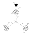
図1は、第1の実施形態における飛行システム10の構成例を示す模式図である。飛行システム10は、無人航空機100、送信機50、及び携帯端末80を備える。無人航空機100、送信機50、及び携帯端末80は、相互に有線通信又は無線通信(例えば無線LAN(Local Area Network))により通信可能である。(First Embodiment)
FIG. 1 is a schematic diagram showing a configuration example of the
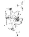
次に、無人航空機100の構成例について説明する。図2は、無人航空機100の外観の一例を示す図である。図3は、無人航空機100の具体的な外観の一例を示す図である。無人航空機100が移動方向STV0に飛行する時の側面図が図2に示され、無人航空機100が移動方向STV0に飛行する時の斜視図が図3に示されている。
Next, a configuration example of the unmanned
図2及び図3に示すように、地面と平行であって移動方向STV0に沿う方向にロール軸(x軸参照)が定義されたとする。この場合、地面と平行であってロール軸に垂直な方向にピッチ軸(y軸参照)が定められ、更に、地面に垂直であってロール軸及びピッチ軸に垂直な方向にヨー軸(z軸参照)が定められる。 As shown in FIGS. 2 and 3, it is assumed that the roll axis (see x-axis) is defined in the direction parallel to the ground and along the moving direction STV0. In this case, the pitch axis (see y-axis) is defined in a direction parallel to the ground and perpendicular to the roll axis, and further, a yaw axis (z-axis) is defined in a direction perpendicular to the ground and perpendicular to the roll axis and the pitch axis. See) is defined.
無人航空機100は、UAV本体102と、ジンバル200と、撮像装置220と、複数の撮像装置230とを含む構成である。撮像装置220、230は、撮像部の一例である。
The unmanned
UAV本体102は、複数の回転翼(プロペラ)を備える。UAV本体102は、複数の回転翼の回転を制御することにより無人航空機100を飛行させる。UAV本体102は、例えば4つの回転翼を用いて無人航空機100を飛行させる。回転翼の数は、4つに限定されない。また、無人航空機100は、回転翼を有さない固定翼機でもよい。
The UAV
撮像装置220は、所望の撮像範囲に含まれる被写体(例えば、空撮対象となる上空の様子、山や川等の景色、地上の建物)を撮像する撮像用のカメラである。
The
複数の撮像装置230は、無人航空機100の飛行を制御するために無人航空機100の周囲を撮像するセンシング用のカメラである。2つの撮像装置230が、無人航空機100の機首である正面に設けられてよい。さらに、他の2つの撮像装置230が、無人航空機100の底面に設けられてよい。正面側の2つの撮像装置230はペアとなり、いわゆるステレオカメラとして機能してよい。底面側の2つの撮像装置230もペアとなり、ステレオカメラとして機能してよい。複数の撮像装置230により撮像された画像に基づいて、無人航空機100の周囲の3次元空間データが生成されてよい。なお、無人航空機100が備える撮像装置230の数は4つに限定されない。無人航空機100は、少なくとも1つの撮像装置230を備えていればよい。無人航空機100は、無人航空機100の機首、機尾、側面、底面、及び天井面のそれぞれに少なくとも1つの撮像装置230を備えてよい。撮像装置230で設定できる画角は、撮像装置220で設定できる画角より広くてよい。撮像装置230は、単焦点レンズ又は魚眼レンズを有してよい。
The plurality of
図4は、無人航空機100のハードウェア構成の一例を示すブロック図である。無人航空機100は、UAV制御部110と、通信インタフェース150と、メモリ160と、ジンバル200と、回転翼機構210と、撮像装置220と、撮像装置230と、GPS受信機240と、慣性計測装置(IMU:Inertial Measurement Unit)250と、磁気コンパス260と、気圧高度計270と、超音波センサ280と、レーザー測定器290と、を含む構成である。通信インタフェース150は、通信部の一例である。超音波センサ280及びレーザー測定器290は、測距センサの一例である。
FIG. 4 is a block diagram showing an example of the hardware configuration of the unmanned
UAV制御部110は、例えばCPU(Central Processing Unit)、MPU(Micro Processing Unit)又はDSP(Digital Signal Processor)を用いて構成される。UAV制御部110は、無人航空機100の各部の動作を統括して制御するための信号処理、他の各部との間のデータの入出力処理、データの演算処理及びデータの記憶処理を行う。
The
UAV制御部110は、メモリ160に格納されたプログラムに従って無人航空機100の飛行を制御する。UAV制御部110は、通信インタフェース150を介して遠隔の送信機50から受信した命令に従って、無人航空機100の飛行を制御する。メモリ160は無人航空機100から取り外し可能であってもよい。
The
UAV制御部110は、複数の撮像装置230により撮像された複数の画像を解析することで、無人航空機100の周囲の環境を特定してよい。UAV制御部110は、無人航空機100の周囲の環境に基づいて、例えば障害物を回避して飛行を制御する。
The
UAV制御部110は、現在の日時を示す日時情報を取得する。UAV制御部110は、GPS受信機240から現在の日時を示す日時情報を取得してよい。UAV制御部110は、無人航空機100に搭載されたタイマ(不図示)から現在の日時を示す日時情報を取得してよい。
The
UAV制御部110は、無人航空機100の位置を示す位置情報を取得する。UAV制御部110は、GPS受信機240から、無人航空機100が存在する緯度、経度及び高度を示す位置情報を取得してよい。UAV制御部110は、GPS受信機240から無人航空機100が存在する緯度及び経度を示す緯度経度情報、並びに気圧高度計270から無人航空機100が存在する高度を示す高度情報をそれぞれ位置情報として取得してよい。UAV制御部110は、超音波センサ280による超音波の放射点と超音波の反射点との距離を高度情報として取得してよい。
The
UAV制御部110は、磁気コンパス260から無人航空機100の向きを示す向き情報を取得する。向き情報には、例えば無人航空機100の機首の向きに対応する方位が示される。
The
UAV制御部110は、撮像装置220が撮像すべき撮像範囲を撮像する時に無人航空機100が存在すべき位置を示す位置情報を取得してよい。UAV制御部110は、無人航空機100が存在すべき位置を示す位置情報をメモリ160から取得してよい。UAV制御部110は、無人航空機100が存在すべき位置を示す位置情報を、通信インタフェース150を介して送信機50等の他の装置から取得してよい。UAV制御部110は、3次元地図データベースを参照して、撮像すべき撮像範囲を撮像するために、無人航空機100が存在可能な位置を特定して、その位置を無人航空機100が存在すべき位置を示す位置情報として取得してよい。
The
UAV制御部110は、撮像装置220及び撮像装置230のそれぞれの撮像範囲を示す撮像情報を取得する。UAV制御部110は、撮像範囲を特定するためのパラメータとして、撮像装置220及び撮像装置230の画角を示す画角情報を撮像装置220及び撮像装置230から取得する。UAV制御部110は、撮像範囲を特定するためのパラメータとして、撮像装置220及び撮像装置230の撮像方向を示す情報を取得する。UAV制御部110は、例えば撮像装置220の撮像方向を示す情報として、ジンバル200から撮像装置220の姿勢の状態を示す姿勢情報を取得する。UAV制御部110は、無人航空機100の向きを示す情報を取得する。撮像装置220の姿勢の状態を示す情報は、ジンバル200のピッチ軸及びヨー軸の基準回転角度からの回転角度を示す。UAV制御部110は、撮像範囲を特定するためのパラメータとして、無人航空機100が存在する位置を示す位置情報を取得する。UAV制御部110は、撮像装置220及び撮像装置230の画角及び撮像方向、並びに無人航空機100が存在する位置に基づいて、撮像装置220が撮像する地理的な範囲を示す撮像範囲を画定し、撮像範囲を示す撮像情報を生成することで、撮像情報を取得してよい。
The
UAV制御部110は、撮像装置220が撮像すべき撮像範囲を示す撮像情報を取得してよい。UAV制御部110は、メモリ160から撮像装置220が撮像すべき撮像情報を取得してよい。UAV制御部110は、通信インタフェース150を介して送信機50等の他の装置から撮像装置220が撮像すべき撮像情報を取得してよい。
The
UAV制御部110は、無人航空機100の周囲に存在するオブジェクトの立体形状(3次元形状)を示す立体情報(3次元情報)を取得してよい。オブジェクトは、例えば、建物、道路、車、木等の風景の一部である。立体情報は、例えば、3次元空間データである。UAV制御部110は、複数の撮像装置230から得られたそれぞれの画像から、無人航空機100の周囲に存在するオブジェクトの立体形状を示す立体情報を生成することで、立体情報を取得してよい。UAV制御部110は、メモリ160に格納された3次元地図データベースを参照することにより、無人航空機100の周囲に存在するオブジェクトの立体形状を示す立体情報を取得してよい。UAV制御部110は、ネットワーク上に存在するサーバが管理する3次元地図データベースを参照することで、無人航空機100の周囲に存在するオブジェクトの立体形状に関する立体情報を取得してよい。
The
UAV制御部110は、撮像装置220及び撮像装置230により撮像された画像データを取得する。
The
UAV制御部110は、ジンバル200、回転翼機構210、撮像装置220、及び撮像装置230を制御する。UAV制御部110は、撮像装置220の撮像方向又は画角を変更することによって、撮像装置220の撮像範囲を制御する。UAV制御部110は、ジンバル200の回転機構を制御することで、ジンバル200に支持されている撮像装置220の撮像範囲を制御する。
The
本明細書では、撮像範囲は、撮像装置220又は撮像装置230により撮像される地理的な範囲をいう。撮像範囲は、緯度、経度、及び高度で定義される。撮像範囲は、緯度、経度、及び高度で定義される3次元空間データにおける範囲でよい。撮像範囲は、撮像装置220又は撮像装置230の画角及び撮像方向、並びに無人航空機100が存在する位置に基づいて特定される。撮像装置220及び撮像装置230の撮像方向は、撮像装置220及び撮像装置230の撮像レンズが設けられた正面が向く方位と俯角とから定義される。撮像装置220の撮像方向は、無人航空機100の機首の方位と、ジンバル200に対する撮像装置220の姿勢の状態とから特定される方向である。撮像装置230の撮像方向は、無人航空機100の機首の方位と、撮像装置230が設けられた位置とから特定される方向である。
In the present specification, the imaging range refers to a geographical range imaged by the
UAV制御部110は、回転翼機構210を制御することで、無人航空機100の飛行を制御する。つまり、UAV制御部110は、回転翼機構210を制御することにより、無人航空機100の緯度、経度、及び高度を含む位置を制御する。UAV制御部110は、無人航空機100の飛行を制御することにより、撮像装置220及び撮像装置230の撮像範囲を制御してよい。UAV制御部110は、撮像装置220が備えるズームレンズを制御することで、撮像装置220の画角を制御してよい。UAV制御部110は、撮像装置220のデジタルズーム機能を利用して、デジタルズームにより、撮像装置220の画角を制御してよい。
The
撮像装置220が無人航空機100に固定され、撮像装置220を動かせない場合、UAV制御部110は、特定の日時に特定の位置に無人航空機100を移動させることにより、所望の環境下で所望の撮像範囲を撮像装置220に撮像させることができる。あるいは撮像装置220がズーム機能を有さず、撮像装置220の画角を変更できない場合でも、UAV制御部110は、特定された日時に、特定の位置に無人航空機100を移動させることで、所望の環境下で所望の撮像範囲を撮像装置220に撮像させることができる。
When the
UAV制御部110は、例えば通信インタフェース150を介して、連携して飛行する飛行グループに属する複数の無人航空機100の相対的な位置情報を取得してよい。UAV制御部110は、相対的な位置情報をメモリ160に保持させることで、この相対的な位置情報を設定してよい。したがって、UAV制御部110は、設定部の一例である。相対的な位置情報を設定することで、相対的な位置情報を加味して(例えば相対的な位置関係を維持して)、飛行制御することが可能となる。
The
通信インタフェース150は、送信機50と通信する。通信インタフェース150は、遠隔の送信機50からUAV制御部110に対する各種の命令や情報を受信する。
The
メモリ160は、UAV制御部110がジンバル200、回転翼機構210、撮像装置220、撮像装置230、GPS受信機240、慣性計測装置250、磁気コンパス260、気圧高度計270、超音波センサ280、及びレーザー測定器290を制御するのに必要なプログラム等を格納する。メモリ160は、コンピュータ読み取り可能な記録媒体でよく、SRAM(Static Random Access Memory)、DRAM(Dynamic Random Access Memory)、EPROM(Erasable Programmable Read Only Memory)、EEPROM(Electrically Erasable Programmable Read-Only Memory)、及びUSBメモリ等のフラッシュメモリの少なくとも1つを含んでよい。メモリ160は、UAV本体102の内部に設けられてよい。UAV本体102から取り外し可能に設けられてよい。
The
ジンバル200は、少なくとも1つの軸を中心に撮像装置220を回転可能に支持する。ジンバル200は、ヨー軸、ピッチ軸、及びロール軸を中心に撮像装置220を回転可能に支持してよい。ジンバル200は、ヨー軸、ピッチ軸、及びロール軸の少なくとも1つを中心に撮像装置220を回転させることで、撮像装置220の撮像方向を変更してよい。
The
回転翼機構210は、複数の回転翼211と、複数の回転翼211を回転させる複数の駆動モータ212と、駆動モータ212を駆動するための駆動電流の電流値(実測値)を計測する電流センサ213と、を有する。駆動電流は、駆動モータ212に供給される。
The
撮像装置220は、所望の撮像範囲の被写体を撮像して撮像画像のデータを生成する。撮像装置220の撮像により得られた画像データは、撮像装置220が有するメモリ、又はメモリ160に格納される。
The
撮像装置230は、無人航空機100の周囲を撮像して撮像画像のデータを生成する。撮像装置230の画像データは、メモリ160に格納される。
The
GPS受信機240は、複数の航法衛星(つまり、GPS衛星)から発信された時刻及び各GPS衛星の位置(座標)を示す複数の信号を受信する。GPS受信機240は、受信された複数の信号に基づいて、GPS受信機240の位置(つまり、無人航空機100の位置)を算出する。GPS受信機240は、無人航空機100の位置情報をUAV制御部110に出力する。なお、GPS受信機240の位置情報の算出は、GPS受信機240の代わりにUAV制御部110により行われてよい。この場合、UAV制御部110には、GPS受信機240が受信した複数の信号に含まれる時刻及び各GPS衛星の位置を示す情報が入力される。
The
慣性計測装置250は、無人航空機100の姿勢を検出し、検出結果をUAV制御部110に出力する。慣性計測装置IMU250は、無人航空機100の姿勢として、無人航空機100の前後、左右、及び上下の3軸方向の加速度と、ピッチ軸、ロール軸、及びヨー軸の3軸方向の角速度とを検出する。
The
磁気コンパス260は、無人航空機100の機首の方位を検出し、検出結果をUAV制御部110に出力する。
The
気圧高度計270は、無人航空機100が飛行する高度を検出し、検出結果をUAV制御部110に出力する。
The
超音波センサ280は、超音波を放射し、地面や物体により反射された超音波を検出し、検出結果をUAV制御部110に出力する。検出結果は、無人航空機100から地面までの距離つまり高度を示してよい。検出結果は、無人航空機100から物体までの距離を示してよい。
The
レーザー測定器290は、物体にレーザー光を照射し、物体で反射された反射光を受光し、反射光により無人航空機100と物体との間の距離を測定する。レーザー光による距離の測定方式は、一例として、タイムオブフライト方式でよい。
The
次に、送信機50及び携帯端末80の構成例について説明する。図5は、送信機50が装着された携帯端末80の外観の一例を示す斜視図である。図5では、携帯端末80の一例として、スマートフォン80Sが示されている。送信機50に対する上下前後左右の方向は、図5に示す矢印の方向にそれぞれ従うとする。送信機50は、例えば送信機50を使用する人物(以下、「操作者」という)の両手で把持された状態で使用される。
Next, a configuration example of the
送信機50は、例えば略正方形状の底面を有し、かつ高さが底面の一辺より短い略直方体(言い換えると、略箱形)の形状をした樹脂製の筐体50Bを有する。送信機50の筐体表面の略中央には、左制御棒53Lと右制御棒53Rとが突設して配置される。
The
左制御棒53L、右制御棒53Rは、それぞれ操作者による無人航空機100の移動を遠隔で制御(例えば、無人航空機100の前後移動、左右移動、上下移動、向き変更)するための操作において使用される。図5では、左制御棒53L及び右制御棒53Rは、操作者の両手からそれぞれ外力が印加されていない初期状態の位置が示されている。左制御棒53L及び右制御棒53Rは、操作者により印加された外力が解放された後、自動的に所定位置(例えば図5に示す初期位置)に復帰する。
The
左制御棒53Lの手前側(言い換えると、操作者側)には、送信機50の電源ボタンB1が配置される。電源ボタンB1が操作者により一度押下されると、例えば送信機50に内蔵されるバッテリ(不図示)の容量の残量がバッテリ残量表示部L2において表示される。電源ボタンB1が操作者によりもう一度押下されると、例えば送信機50の電源がオンとなり、送信機50の各部(図7参照)に電源が供給されて使用可能となる。
The power button B1 of the
右制御棒53Rの手前側(言い換えると、操作者側)には、RTH(Return To Home)ボタンB2が配置される。RTHボタンB2が操作者により押下されると、送信機50は、無人航空機100に所定の位置に自動復帰させるための信号を送信する。これにより、送信機50は、無人航空機100を所定の位置(例えば無人航空機100が記憶している離陸位置)に自動的に帰還させることができる。RTHボタンB2は、例えば屋外での無人航空機100による空撮中に操作者が無人航空機100の機体を見失った場合、又は電波干渉や予期せぬトラブルに遭遇して操作不能になった場合等に利用可能である。
The RTH (Return To Home) button B2 is arranged on the front side (in other words, the operator side) of the
電源ボタンB1及びRTHボタンB2の手前側(言い換えると、操作者側)には、リモートステータス表示部L1及びバッテリ残量表示部L2が配置される。リモートステータス表示部L1は、例えばLED(Light Emission Diode)を用いて構成され、送信機50と無人航空機100との無線の接続状態を表示する。バッテリ残量表示部L2は、例えばLEDを用いて構成され、送信機50に内蔵されたバッテリ(不図示)の容量の残量を表示する。
A remote status display unit L1 and a battery remaining amount display unit L2 are arranged on the front side (in other words, the operator side) of the power button B1 and the RTH button B2. The remote status display unit L1 is configured by using, for example, an LED (Light Emission Diode), and displays the wireless connection status between the
左制御棒53L及び右制御棒53Rより後側であって、かつ送信機50の筐体50Bの後方側面から、2つのアンテナAN1,AN2が突設して配置される。アンテナAN1,AN2は、操作者の左制御棒53L及び右制御棒53Rの操作に基づき、送信機制御部61により生成された信号(つまり、無人航空機100の移動を制御するための信号)を無人航空機100に送信する。この信号は、送信機50により入力された操作入力信号の1つである。アンテナAN1,AN2は、例えば2kmの送受信範囲をカバーできる。また、アンテナAN1,AN2は、送信機50と無線接続中の無人航空機100が有する撮像装置220,230により撮像された画像、又は無人航空機100が取得した各種データが無人航空機100から送信された場合に、これらの画像又は各種データを受信できる。
Two antennas AN1 and AN2 are arranged so as to project from the rear side of the
図5では、送信機50が表示部を備えていないが、表示部を備えてもよい。
In FIG. 5, the
携帯端末80は、ホルダHLDに載置されて取り付けられてよい。ホルダHLDは、送信機50に接合されて取り付けられてよい。これにより、携帯端末80がホルダHLDを介して送信機50に装着される。携帯端末80と送信機50とは、有線ケーブル(例えばUSBケーブル)を介して接続されてよい。携帯端末80が送信機50に装着されず、携帯端末80と送信機50がそれぞれ独立して設けられてもよい。
The
図6は、送信機50及び携帯端末80の外観の一例を示す斜視図である。図6では、携帯端末80の一例として、タブレット80Tが示されている。
FIG. 6 is a perspective view showing an example of the appearance of the
図7は、送信機50のハードウェア構成の一例を示すブロック図である。送信機50は、左制御棒53Lと、右制御棒53Rと、送信機制御部61と、無線通信部63と、インタフェース部65と、電源ボタンB1と、RTHボタンB2と、操作部セットOPSと、リモートステータス表示部L1と、バッテリ残量表示部L2と、表示部DPとを含む構成である。送信機50は、無人航空機100の制御を指示する操作装置の一例である。
FIG. 7 is a block diagram showing an example of the hardware configuration of the
左制御棒53Lは、例えば操作者の左手により、無人航空機100の移動を遠隔で制御するための操作に使用される。右制御棒53Rは、例えば操作者の右手により、無人航空機100の移動を遠隔で制御するための操作に使用される。無人航空機100の移動は、例えば前進する方向の移動、後進する方向の移動、左方向の移動、右方向の移動、上昇する方向の移動、下降する方向の移動、左方向に無人航空機100を回転する移動、右方向に無人航空機100を回転する移動のうちいずれか又はこれらの組み合わせであり、以下同様である。
The
電源ボタンB1は一度押下されると、一度押下された旨の信号が送信機制御部61に入力される。送信機制御部61は、この信号に従い、送信機50に内蔵されるバッテリ(不図示)の容量の残量をバッテリ残量表示部L2に表示する。これにより、操作者は、送信機50に内蔵されるバッテリの容量の残量を簡単に確認できる。また、電源ボタンB1は二度押下されると、二度押下された旨の信号が送信機制御部61に渡される。送信機制御部61は、この信号に従い、送信機50に内蔵されるバッテリ(不図示)に対し、送信機50内の各部への電源供給を指示する。これにより、操作者は、送信機50の電源がオンとなり、送信機50の使用を簡単に開始できる。
When the power button B1 is pressed once, a signal indicating that the power button B1 is pressed once is input to the
RTHボタンB2は押下されると、押下された旨の信号が送信機制御部61に入力される。送信機制御部61は、この信号に従い、無人航空機100に所定の位置(例えば無人航空機100の離陸位置)に自動復帰させるための信号を生成し、無線通信部63及びアンテナAN1,AN2を介して無人航空機100に送信する。これにより、操作者は、送信機50に対する簡単な操作により、無人航空機100を所定の位置に自動で復帰(帰還)させることができる。
When the RTH button B2 is pressed, a signal indicating that it is pressed is input to the
操作部セットOPSは、複数の操作部OP(例えば操作部OP1,…,操作部OPn)(n:2以上の整数)を用いて構成される。操作部セットOPSは、図4に示す左制御棒53L、右制御棒53R、電源ボタンB1及びRTHボタンB2を除く他の操作部(例えば、送信機50による無人航空機100の遠隔制御を支援するための各種の操作部)により構成される。ここでいう各種の操作部とは、例えば、無人航空機100の撮像装置220を用いた静止画の撮像を指示するボタン、無人航空機100の撮像装置220を用いた動画の録画の開始及び終了を指示するボタン、無人航空機100のジンバル200(図4参照)のチルト方向の傾きを調整するダイヤル、無人航空機100のフライトモードを切り替えるボタン、無人航空機100の撮像装置220の設定を行うダイヤルが該当する。
The operation unit set OPS is configured by using a plurality of operation unit OPs (for example, operation unit OP1, ..., Operation unit OPn) (n: an integer of 2 or more). The operation unit set OPS is for supporting remote control of the unmanned
リモートステータス表示部L1及びバッテリ残量表示部L2は、図6を参照して説明したので、ここでは説明を省略する。 Since the remote status display unit L1 and the battery remaining amount display unit L2 have been described with reference to FIG. 6, description thereof will be omitted here.
送信機制御部61は、プロセッサ(例えばCPU、MPU又はDSP)を用いて構成される。送信機制御部61は、送信機50の各部の動作を統括して制御するための信号処理、他の各部との間のデータの入出力処理、データの演算処理及びデータの記憶処理を行う。
The
送信機制御部61は、無人航空機100の撮像装置220が撮像した撮像画像のデータを、無線通信部63を介して取得してメモリ(不図示)に保存し、インタフェース部65を介して携帯端末80に出力してよい。言い換えると、送信機制御部61は、無人航空機100の撮像装置220により撮像された空撮画像のデータを携帯端末80に表示させてよい。これにより、無人航空機100の撮像装置220により撮像された空撮画像は、携帯端末80において表示可能となる。
The
送信機制御部61は、操作者の左制御棒53L及び右制御棒53Rの操作により、その操作により指定された無人航空機100の飛行を制御するための指示信号を生成してよい。送信機制御部61は、この指示信号を、無線通信部63及びアンテナAN1,AN2を介して、無人航空機100に送信して無人航空機100を遠隔制御してよい。これにより、送信機50は、無人航空機100の移動を遠隔で制御できる。
The
送信機制御部61は、送信機50が有する任意のボタンや任意の操作部への操作に基づく操作入力信号を生成し、無線通信部63を介して、操作入力信号を無人航空機100に送信してよい。この場合、無人航空機100は、操作入力信号を送信機50から受信することで、送信機50の操作者の制御下にあることを認識可能である。
The
無線通信部63は、2つのアンテナAN1,AN2と接続される。無線通信部63は、2つのアンテナAN1,AN2を介して、無人航空機100との間で所定の無線通信方式(例えばWifi(登録商標))を用いた情報やデータの送受信を行う。
The
インタフェース部65は、送信機50と携帯端末80との間の情報やデータの入出力を行う。インタフェース部65は、例えば送信機50に設けられたUSBポート(不図示)でよい。インタフェース部65は、USBポート以外のインタフェースでもよい。
The
図8は、携帯端末80のハードウェア構成の一例を示すブロック図である。携帯端末80は、プロセッサ81、インタフェース部82、操作部83、無線通信部85、メモリ87、及びディスプレイ88を備えてよい。携帯端末80は、位置処理装置の一例である。
FIG. 8 is a block diagram showing an example of the hardware configuration of the
プロセッサ81は、例えばCPU、MPU又はDSPを用いて構成される。プロセッサ81は、携帯端末80の各部の動作を統括して制御するための信号処理、他の各部との間のデータの入出力処理、データの演算処理及びデータの記憶処理を行う。
The
プロセッサ81は、無線通信部85を介して、無人航空機100からのデータや情報を取得してよい。プロセッサ81は、インタフェース部82を介して、送信機50からのデータや情報を取得してよい。プロセッサ81は、操作部83を介して入力されたデータや情報を取得してよい。プロセッサ81は、メモリ87に保持されたデータや情報を取得してよい。プロセッサ81は、データや情報をディスプレイ88に送り、このデータや情報に基づく表示情報をディスプレイ88に表示させてよい。
The
プロセッサ81は、無人航空機100の制御を指示するためのアプリケーションを実行する。アプリケーションは、複数の無人航空機100を協調して飛行させるための相対的な位置情報を処理するための相対位置処理アプリケーションを含んでよい。プロセッサ81は、アプリケーションで用いられる各種のデータを生成してよい。
The
インタフェース部82は、送信機50と携帯端末80との間の情報やデータの入出力を行う。インタフェース部82は、例えば携帯端末80に設けられたUSBコネクタ(不図示)でよい。インタフェース部65は、USBコネクタ以外のインタフェースでもよい。
The
操作部83は、携帯端末80の操作者により入力されるデータや情報を受け付ける。操作部83は、ボタン、キー、タッチパネル、マイクロホン、等を含んでよい。ここでは、主に、操作部83とディスプレイ88とがタッチパネルにより構成されることを例示する。この場合、操作部83は、タッチ操作、タップ操作、ドラック操作等を受付可能である。
The
無線通信部85は、各種の無線通信方式により、無人航空機100Bとの間で通信する無線通信方式は、例えば、無線LAN、Bluetooth(登録商標)、近距離無線通信、又は公衆無線回線を介した通信を含んでよい。無線通信部85は、出力部の一例である。
The
メモリ87は、例えば携帯端末80の動作を規定するプログラムや設定値のデータが格納されたROMと、プロセッサ81の処理時に使用される各種の情報やデータを一時的に保存するRAMを有してよい。メモリ87は、ROM及びRAM以外のメモリが含まれてよい。メモリ87は、携帯端末80の内部に設けられてよい。メモリ87は、携帯端末80から取り外し可能に設けられてよい。プログラムは、アプリケーションプログラムを含んでよい。
The
ディスプレイ88は、例えばLCD(Liquid Crystal Display)を用いて構成され、プロセッサ81から出力された各種の情報やデータを表示する。ディスプレイ88は、無人航空機100の撮像装置220により撮像された空撮画像のデータを表示してよい。ディスプレイ88は、相対位置処理アプリケーションで用いられる相対位置処理画面を表示してよい。
The
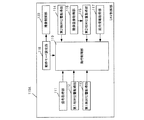
図9は、携帯端末80の機能構成の一例を示すブロック図である。プロセッサ81は、メモリ87に保持されたプログラムを実行することで、UAV指定部811、位置情報取得部812、相対位置処理部813、及び撮像情報処理部814の機能を有する。UAV指定部811は、選択部の一例である。位置情報取得部812は、取得部の一例である。相対位置処理部813は、決定部の一例である。
FIG. 9 is a block diagram showing an example of the functional configuration of the
UAV指定部811は、複数(例えば3台)の無人航空機100の中から、1つの飛行グループを形成する複数(例えば2台)の無人航空機100を指定(選択)する。つまり、UAV指定部811は、複数の無人航空機100を指定して、1つ以上の飛行グループを形成する。UAV指定部811は、操作部83に入力された指定情報を基に、無人航空機100を指定してよい。操作部83に入力された指定情報は、タッチパネルへのタッチ情報でもよいし、無人航空機100を識別するための識別情報の入力(例えばキー入力、ボタン入力、音声入力)でもよい。
The
UAV指定部811は、各種の処理画面(例えば相対位置処理画面)において表示された複数の無人航空機100のうち、操作部83を介して、飛行グループを形成する無人航空機100を指定してよい。処理画面に表示される複数の無人航空機100の位置は、位置情報取得部812により取得された各無人航空機100の位置情報に基づいて決定されてよい。
The
位置情報取得部812は、無人航空機100の位置情報(例えば現在位置の情報)を取得する。位置情報取得部812は、例えば無線通信部85を介して、無人航空機100の位置情報を取得してよい。位置情報取得部812は、例えば送信機50及びインタフェース部82を介して、無人航空機100の位置情報を取得してよい。この無人航空機100の位置情報は、無人航空機100の絶対位置の情報でよい。
The position
無人航空機100の位置情報は、無人航空機100のGPS受信機240により受信された位置情報を含んでよい。無人航空機100の位置情報は、3次元地図データベースを参照して得られた位置情報を含んでよい。無人航空機100の位置情報は、気圧高度計270、超音波センサ280、又はレーザー測定器290により得られた高度情報を含んでよい。
The position information of the unmanned
なお、本実施形態では、絶対位置の情報は、1つの無人航空機100等の物体の位置により規定される位置情報(例えば緯度、経度、高度の情報)である。これに対し、相対位置の情報は、複数の無人航空機等の物体間の位置関係により規定される位置情報(例えば何らかの基準の位置に対する距離、方向の情報)でよい。
In the present embodiment, the absolute position information is position information (for example, latitude, longitude, altitude information) defined by the position of an object such as one unmanned
相対位置処理部813は、同じ飛行グループに含まれる複数の無人航空機100の相対的な位置情報を決定する。複数の無人航空機100の相対的な位置情報は、複数の無人航空機100の各々の相対的な位置関係の情報とも言える。相対位置処理部813は、複数の無人航空機100の飛行中且つ送信機50による飛行操作中における相対的な位置関係を決定してよい。
The relative
相対位置処理部813は、同じ飛行グループに含まれる複数の無人航空機100のうち特定の1台の無人航空機100を基準として、この無人航空機100に対するその他の無人航空機100のそれぞれの位置の情報を、相対的な位置情報として決定してよい。
The relative
相対位置処理部813は、同じ飛行グループに含まれる複数の無人航空機100の位置(絶対位置)を基に、飛行グループにおける基準となる位置(基準位置)を決定してよい。相対位置処理部813は、基準位置を基準として、基準位置に対する複数の無人航空機100の各々の位置の情報を、相対的な位置情報として決定してよい。
The relative
相対位置処理部813は、各種の処理画面(例えば相対位置処理画面)において表示された複数の無人航空機100のうち、操作部83を介して、相対位置の設定対象の無人航空機100の位置をドラッグ操作により変更し、相対的な位置情報を変更してよい。つまり、相対位置処理部813は、ドラッグ操作により、相対的な位置情報を調整してよい。相対位置処理部813は、操作部83を介して、複数の無人航空機100の間の距離の値を取得し、この距離に基づいて相対的な位置情報を決定してよい。
The relative
次に、同じ飛行グループに属する複数の無人航空機100の相対的な位置情報の決定例について説明する。
Next, an example of determining the relative position information of a plurality of unmanned
同じ飛行グループに含まれる複数の無人航空機100は、各々が協調して飛行してよい。飛行グループは、携帯端末80により形成されてよい。相対的な位置情報は、携帯端末80により決定されてよい。
The plurality of unmanned
図10は、位置関係処理画面SGにおける同じ飛行グループに属する無人航空機100の指定例を示す図である。位置関係処理画面SGは、ディスプレイ88の少なくとも一部に表示されてよい。以降の位置関係処理画面SGでも同様である。
FIG. 10 is a diagram showing a designated example of the unmanned
図10の位置関係処理画面SGには、UAV画像G11〜G13が表示されている。UAV画像G11,G12,G13は、各無人航空機100の絶対位置に対応して表示され、3台の無人航空機100G11,100G12,100G13(いずれも不図示)の各々の位置を示す。位置関係処理画面SGにより示されるエリアは、実空間における無人航空機100が置かれたエリアに対応し、実空間のエリアに対して所定の縮尺で示されてよい。位置関係処理画面SGにおけるUAV画像G11〜G13の表示位置は、位置情報取得部812により取得された絶対位置に応じた位置でよい。UAV画像は、飛行体画像の一例である。
UAV images G11 to G13 are displayed on the positional relationship processing screen SG of FIG. 10. The UAV images G11, G12, and G13 are displayed corresponding to the absolute positions of each unmanned
図10では、UAV画像G11が見やすい位置となるよう、UAV画像G11が位置関係処理画面SGの中心に位置するように表示されてよい。尚、他のUAV画像G11が中心に位置するように表示されてもよい。 In FIG. 10, the UAV image G11 may be displayed so as to be located at the center of the positional relationship processing screen SG so that the UAV image G11 is in an easily visible position. The other UAV image G11 may be displayed so as to be located at the center.
図10では、操作部83は、UAV画像G11,G12に対するタッチ操作を受け付ける。相対位置処理部813は、操作部83へのこのタッチ操作の情報を取得し、UAV画像G11,G12に対応する無人航空機100G11,100G12を、飛行グループを形成するための無人航空機100として指定する。一方、相対位置処理部813は、操作部83を介したUAV画像G13へのタッチ操作の情報を取得しないので、UAV画像G13に対応する無人航空機100G13を、飛行グループを形成するための無人航空機100として指定しない。
In FIG. 10, the
図11は、位置関係処理画面SGにおける無人航空機100の水平方向の位置の調整例を示す図である。図11では、選択された複数の無人航空機100を上方から見た位置関係を示してよい。
FIG. 11 is a diagram showing an example of adjusting the position of the unmanned
図11では、図10の位置関係処理画面SGにおいて選択されたUAV画像G11,G12が表示され、選択されなかったUAV画像G13は表示されていない。図11では、操作部83は、UAV画像G12に対するドラッグ操作を受け付けてよい。相対位置処理部813は、操作部83へのこのドラッグ操作の情報を取得し、ドラッグ操作に応じてUAV画像G12の表示位置を変更する。図11では、水平方向の座標を示すxy座標において、無人航空機100G11に対する無人航空機100G12の距離が、x方向に沿って距離L1(例えば50cm)となり、y方向に沿って距離0となるように、相対位置処理部813は、位置関係処理画面SGにおけるUAV画像G12の位置を、操作部83を介して調整する。この場合、UAV画像G12aからUAV画像G12bの位置へドラッグ操作される。ディスプレイ88は、このドラッグ操作に応じて、相対的な位置情報(例えば距離の情報)を表示してよい。これにより、携帯端末80の操作者は、ドラッグ操作によって変更された距離を具体的に理解できる。
In FIG. 11, the selected UAV images G11 and G12 are displayed on the positional relationship processing screen SG of FIG. 10, and the unselected UAV images G13 are not displayed. In FIG. 11, the
なお、図11において、各UAV画像G12内に描かれた矢印arは、撮像装置220又は230の向き、つまり撮像方向を示している。このことは、以降でも同じである。撮像装置220がメインカメラとして機能してよい。撮像装置230がサブカメラとして機能してよい。
In FIG. 11, the arrow ar drawn in each UAV image G12 indicates the direction of the
図12は、位置関係処理画面SGにおける無人航空機100の高さ方向(重力方向)の位置の調整例を示す図である。図12では、選択された複数の無人航空機100を水平方向から見た位置関係を示してよい。
FIG. 12 is a diagram showing an example of adjusting the position of the unmanned
図12では、図10の位置関係処理画面SG1において選択されたUAV画像G11,G12が表示され、選択されなかったUAV画像G13は表示されていない。図12では、操作部83は、UAV画像G12に対するドラッグ操作を受け付けてよい。相対位置処理部813は、操作部83へのこのドラッグ操作の情報を取得し、ドラッグ操作に応じてUAV画像G12の表示位置を変更する。図12では、高さ方向の座標を示すxz座標において、無人航空機100G11に対する無人航空機100G12の距離が、x方向に沿って距離L1となり、z方向に沿って距離L2(例えば80cm)となるように、相対位置処理部813は、位置関係処理画面SG3におけるUAV画像G12の位置を、操作部83を介して調整する。この場合、UAVG12aからUAV画像G12bの位置へドラッグ操作されてよい。
In FIG. 12, the UAV images G11 and G12 selected on the positional relationship processing screen SG1 of FIG. 10 are displayed, and the UAV images G13 that are not selected are not displayed. In FIG. 12, the
相対的な位置情報の設定時には、位置関係処理画面SG1、SG2、SG3の順に表示され、水平方向、高さ方向の順に相対的な位置情報が決定され、設定されてよい。また、相対的な位置情報の決定時には、位置関係処理画面SG1、SG3、SG2の順に表示され、高さ方向、水平方向の順に相対的な位置情報が決定され、設定されてよい。 When setting the relative position information, the positional relationship processing screens SG1, SG2, and SG3 are displayed in this order, and the relative position information may be determined and set in the order of the horizontal direction and the height direction. Further, when the relative position information is determined, the positional relationship processing screens SG1, SG3, and SG2 are displayed in this order, and the relative position information may be determined and set in the order of the height direction and the horizontal direction.
図11、図12に示した調整例によれば、携帯端末80の操作者は、実際の無人航空機100G11,100G12に対応するUAV画像G11,G12の表示位置をディスプレイ88上で確認しながら、UAV画像G11,G12の位置を簡単に調整できる。携帯端末80は、この簡単な操作により、UAV画像G11とUAV画像G12との間の相対的な位置関係を決定できる。また、携帯端末80の操作者は、3次元空間におけるどの方向(例えば、水平方向、高さ方向)における位置調整であるかを認識して、相対的な位置関係を調整できる。また、携帯端末80の操作者は、表示された画面に対する直感的な操作(例えばドラッグ操作)により、無人航空機100G11,100G12の間の距離を決定できる。
According to the adjustment examples shown in FIGS. 11 and 12, the operator of the
図11,図12とは異なり、操作部83が、無人航空機100G11,100G12の間の具体的な距離の値を入力してもよい。相対位置処理部813は、この距離の情報(例えば水平方向に50cm、高さ方向に80cm)を、相対的な位置情報として決定してもよい。これにより、携帯端末80の操作者は、ディスプレイ88を使用せずに、相対的な位置情報を決定できる。
Unlike FIGS. 11 and 12, the
このように、携帯端末80は、水平方向及び高さ方向を含む3次元空間における相対的な位置情報を決定することで、複数の無人航空機100が飛行可能な飛行範囲である3次元空間での相対的な位置関係を規定できる。よって、携帯端末80は、無人航空機100の飛行の実態に即した相対的な位置情報を決定できる。
In this way, the
なお、3次元空間における相対的な位置情報を決定に限らず、2次元空間における相対的な位置情報を決定してよい。例えば、携帯端末80は、複数の無人航空機100が同一平面上(例えば水平面上)に配置されることを前提として、この平面におけるどの位置に各無人航空機100が配列されるかを決定してもよい。
The relative position information in the three-dimensional space is not limited to the determination, and the relative position information in the two-dimensional space may be determined. For example, the
図13は、飛行グループを形成する複数の無人航空機100の水平方向の基準位置の一例を示す模式図である。図13では、飛行グループは、UAV画像G11,G12に対応する2台の無人航空機100G11,100G12を含む。飛行グループにおける相対的位置関係を決定するための基準となる位置は、基準位置RPで示されている。水平方向の基準位置RPは、同じ飛行グループに含まれる複数の無人航空機100G11,100G12の水平方向の中間位置、中心位置、重心位置、又はその他の基準となる位置でよい。
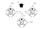
FIG. 13 is a schematic view showing an example of horizontal reference positions of a plurality of unmanned
図13では、基準位置RPの一例として、無人航空機100G11,100G12の水平方向の中心位置が示されている。複数の無人航空機100G11,100G12の相対的な位置情報として、基準位置RPに対する無人航空機100G11,100G12のそれぞれの水平方向の位置の情報が含まれてよい。具体的には、基準位置RPに対する無人航空機100G11の相対的な位置情報は、−x方向に(1/2)×L1の距離である、という情報を含んでよい。また、基準位置RPに対する無人航空機100G12の相対的な位置情報は、+x方向に(1/2)×L1の距離である、という情報を含んでよい。 In FIG. 13, the horizontal center positions of the unmanned aerial vehicles 100G11 and 100G12 are shown as an example of the reference position RP. As the relative position information of the plurality of unmanned aerial vehicles 100G11 and 100G12, information on the horizontal positions of the unmanned aerial vehicles 100G11 and 100G12 with respect to the reference position RP may be included. Specifically, the relative position information of the unmanned aerial vehicle 100G11 with respect to the reference position RP may include information that the distance is (1/2) × L1 in the −x direction. Further, the relative position information of the unmanned aerial vehicle 100G12 with respect to the reference position RP may include information that the distance is (1/2) × L1 in the + x direction.
図14は、飛行グループを形成する複数の無人航空機100の高さ方向の基準位置の一例を示す模式図である。図14では、飛行グループは、UAV画像G11,G12に対応する2台の無人航空機100G11,100G12を含む。飛行グループにおける相対的位置関係を決定するための基準となる位置は、基準位置RPで示されている。高さ方向の基準位置RPは、同じ飛行グループに含まれる複数の無人航空機100G11,100G12の高さ方向の中間位置、中心位置、重心位置、その他の基準となる位置でよい。
FIG. 14 is a schematic view showing an example of reference positions in the height direction of a plurality of unmanned
図14では、基準位置RPの一例として、無人航空機100G11,100G12の高さ方向の中心位置が示されている。複数の無人航空機100G11,100G12間の相対的な位置情報として、基準位置RPに対する無人航空機100G11,100G12のそれぞれの高さ方向の位置の情報が含まれてよい。具体的には、基準位置RPに対する無人航空機100G11の相対的な位置情報は、−z方向に(1/2)×L2の距離である、という情報を含んでよい。また、基準位置RPに対する無人航空機100G12の相対的な位置情報は、+z方向に(1/2)×L2の距離である、という情報を含んでよい。 In FIG. 14, as an example of the reference position RP, the center position of the unmanned aerial vehicles 100G11 and 100G12 in the height direction is shown. As the relative position information between the plurality of unmanned aerial vehicles 100G11 and 100G12, information on the positions of the unmanned aerial vehicles 100G11 and 100G12 in the height direction with respect to the reference position RP may be included. Specifically, the relative position information of the unmanned aerial vehicle 100G11 with respect to the reference position RP may include information that the distance is (1/2) × L2 in the −z direction. Further, the relative position information of the unmanned aerial vehicle 100G12 with respect to the reference position RP may include information that the distance is (1/2) × L2 in the + z direction.
このように、相対位置処理部813は、基準位置RPに対する各無人航空機100の相対的な位置情報を決定してよい。これにより、携帯端末80は、各無人航空機100と基準位置RPとの差分により、容易に相対的な位置情報を生成できる。また、携帯端末80は、複数の無人航空機100が飛行する場合でも、飛行グループの基準位置を基準とした飛行形態にさせることができる。よって、携帯端末80は、複数の無人航空機100に対して、単体の無人航空機100の飛行形態を単純に複数に拡張したような飛行方法を提供でき、送信機50の操作者による無人航空機100の操作を容易化できる。
In this way, the relative
相対位置処理部813は、複数の無人航空機100G11,100G12の相対的な位置情報に、水平方向及び高さ方向の少なくとも一方の距離の情報とともに、無人航空機100G11,100G12の識別情報を含めてもよい。この場合、相対的な位置情報には、無人航空機100G11,100G12の識別情報と距離の情報とが関連付けて含まれてよい。無人航空機100の識別情報は、例えば、製造時に付与される個体識別番号、操作者に設定されるユーザ識別番号、又はその他の識別情報でよい。
The relative
このように、相対的な位置情報に、無人航空機100G11,100G12の識別情報と無人航空機100G11,100G12の相対的な位置情報とが関連付けて含まれてよい。これにより、飛行システム10は、無人航空機100G11の飛行中や送信機50による飛行操作中に、基準位置RP等に対してどの無人航空機100がどの位置を飛行すべきかを規定できる。
As described above, the relative position information may include the identification information of the unmanned aerial vehicles 100G11 and 100G12 and the relative position information of the unmanned aerial vehicles 100G11 and 100G12 in association with each other. Thereby, the
次に、飛行グループを形成する複数の無人航空機100の配列決定例について説明する。
Next, an example of arranging a plurality of unmanned
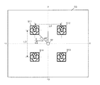
図15は、飛行グループを形成する複数の無人航空機100の第1配列決定例を示す模式図である。
FIG. 15 is a schematic diagram showing a first sequence determination example of a plurality of unmanned
図15では、基準位置RPを中心位置として、基準位置RPの周囲に対称的に4つのUAV画像G11,G12,G13,G14、つまり無人航空機100G11,100G12,100G13,100G14が配列される。図15では、一辺の長さがL3である正方形状の頂点に、各無人航空機100G11,100G12,100G13,100G14が配置される。図15では、無人航空機100G11に対応するUAV画像G11が、xy座標上の中心位置となっている。無人航空機100G11は、相対的な位置情報を処理する携帯端末80が取り付けられた送信機50により飛行の制御が指示される無人航空機100でよい。第1配列決定例は、+y方向が飛行グループの前進時の進行方向でよい。
In FIG. 15, four UAV images G11, G12, G13, and G14, that is, unmanned aerial vehicles 100G11, 100G12, 100G13, and 100G14 are arranged symmetrically around the reference position RP with the reference position RP as the center position. In FIG. 15, each unmanned aerial vehicle 100G11, 100G12, 100G13, 100G14 is arranged at a square apex having a side length of L3. In FIG. 15, the UAV image G11 corresponding to the unmanned aerial vehicle 100G11 is the center position on the xy coordinates. The unmanned aerial vehicle 100G11 may be an unmanned
図16は、飛行グループを形成する複数の無人航空機100の第2配列決定例を示す模式図である。
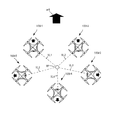
FIG. 16 is a schematic diagram showing a second arrangement determination example of a plurality of unmanned
第2配列決定例は、第1配列決定例とほぼ同じであるが、図16では、基準位置RPがxy座標上の中心位置となっている。図16では、基準位置RPに対する無人航空機100G11の位置が、+y方向から−x方向に45°傾斜した方向に、(1/√2)×L3の距離であるという情報が、相対的な位置情報に含まれてよい。基準位置RPに対する無人航空機100G12,100G13,100G14のそれぞれの位置についても、相対的な位置情報に含まれてよい。第2配列決定例は、+y方向が飛行グループの前進時の進行方向でよい。 The second sequence determination example is almost the same as the first sequence determination example, but in FIG. 16, the reference position RP is the center position on the xy coordinates. In FIG. 16, the information that the position of the unmanned aerial vehicle 100G11 with respect to the reference position RP is a distance of (1 / √2) × L3 in the direction inclined by 45 ° from the + y direction to the −x direction is the relative position information. May be included in. The respective positions of the unmanned aerial vehicles 100G12, 100G13, and 100G14 with respect to the reference position RP may also be included in the relative position information. In the second sequence determination example, the + y direction may be the traveling direction of the flight group when advancing.
図17は、飛行グループを形成する複数の無人航空機100の第3配列決定例を示す模式図である。
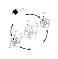
FIG. 17 is a schematic diagram showing a third arrangement determination example of a plurality of unmanned
第3配列決定例では、第2配列決定例と比較すると、各無人航空機100が備える各撮像装置220又は230の向きが異なり、各撮像装置220又は230により撮像される撮像方向が異なる。図17では、相対位置処理部813が、複数の無人航空機100の相対的な位置情報を決定するとともに、撮像情報処理部814が、複数の無人航空機100の各々の撮像方向の情報を決定してよい。撮像情報処理部814は、飛行グループを形成する無人航空機100の台数に基づいて、各無人航空機100の撮像方向の情報を決定してよい。撮像情報処理部814は、同じ飛行グループとして指定された無人航空機100の台数をメモリ87に保持しておき、取得してよい。例えば、飛行グループを形成する無人航空機100の台数が4台である場合、撮像情報処理部814は、1周である360度を均等に4分割した90度ずつ異なる撮像方向の情報を算出して決定してよい。また、撮像情報処理部814は、基準位置RPから複数の無人航空機100の各々を見た方向を、無人航空機100の各々の撮像方向とする撮像方向の情報として決定してよい。
In the third sequence determination example, the orientation of each
図17では、無人航空機100G11が上方向(例えば飛行グループの前進時の進行方向)を撮像方向とし、無人航空機100G12が右方向を撮像方向とし、無人航空機100G13が下方向を撮像方向とし、無人航空機100G14が左方向を撮像方向とする撮像方向の情報が決定されてよい。 In FIG. 17, the unmanned aircraft 100G11 has an upward direction (for example, the traveling direction when the flight group is moving forward) as the imaging direction, the unmanned aircraft 100G12 has the right direction as the imaging direction, and the unmanned aircraft 100G13 has the downward direction as the imaging direction. Information on the imaging direction in which the 100G14 has the left direction as the imaging direction may be determined.
また、撮像情報処理部814は、各無人航空機100の撮像方向を決定する場合、各無人航空機100が備える各撮像装置220又は230の画角の情報を決定してよい。画角に応じて、撮像範囲が決定される。撮像情報処理部814は、飛行グループを形成する無人航空機100の台数に基づいて、各無人航空機100が備える各撮像装置220又は230の画角の情報を決定してよい。撮像情報処理部814は、飛行グループを形成する無人航空機100の台数が4台である場合、1周である360度を均等に4分割した90度以上として画角の情報を算出して決定してよい。
Further, when determining the imaging direction of each unmanned
これにより、この撮像方向や画角の情報に従う各無人航空機100が画像を撮像すると、飛行グループの周囲の360度分の撮像画像が得られる。よって、画像処理装置(例えば携帯端末80)が、これらの撮像画像を取得して所定の画像処理することで、飛行グループの周囲を被写体としたパノラマ画像やステレオ画像を得ることができる。
As a result, when each unmanned
図18は、飛行グループを形成する複数の無人航空機100の第4配列決定例を示す模式図である。
FIG. 18 is a schematic diagram showing an example of determining the fourth arrangement of a plurality of unmanned
第4配列決定例は、第3配列決定例とほぼ同じであるが、飛行グループを形成する無人航空機100の台数が3台であることを想定している。また、UAV画像G11,G12,G13に対応する無人航空機100G11,100G12,100G13が、それぞれ正三角形の頂点の位置に配列されている。したがって、撮像情報処理部814は、1周である360度を均等に3分割した120度ずつ異なる撮像方向の情報を算出して決定してよい。
The fourth sequence determination example is almost the same as the third sequence determination example, but it is assumed that the number of unmanned
図18では、無人航空機100G11が、上方向(例えば飛行グループの前進時の進行方向)を撮像方向とし、無人航空機100G12が、無人航空機100G11の撮像方向を時計周りに120度回転した方向を撮像方向とし、無人航空機100G13が、無人航空機100G12の撮像方向を時計周りに120度回転した方向を撮像方向とする撮像方向の情報が決定されてよい。 In FIG. 18, the unmanned aerial vehicle 100G11 has an upward direction (for example, the traveling direction when the flight group is moving forward) as the imaging direction, and the unmanned aerial vehicle 100G12 has the imaging direction of the unmanned aerial vehicle 100G11 rotated 120 degrees clockwise. Then, the information of the imaging direction in which the imaging direction of the unmanned aerial vehicle 100G13 is rotated by 120 degrees clockwise may be determined.
撮像情報処理部814は、1周である360度を均等に3分割した120度以上として画角の情報を算出して決定してよい。これにより、各無人航空機100が画像を撮像すると、飛行グループの周囲の360度分の撮像画像が得られる。よって、画像処理装置(例えば携帯端末80)が、これらの撮像画像を取得して所定の画像処理することで、飛行グループの周囲を被写体としたパノラマ画像やステレオ画像を得ることができる。
The image pickup
図19は、飛行グループを形成する複数の無人航空機100の第5配列決定例を示す模式図である。
FIG. 19 is a schematic diagram showing a fifth arrangement determination example of a plurality of unmanned
第5配列決定例に示すように、基準位置RPに対して、複数の無人航空機100G11〜100G14が非対称に配列され、相対的な位置情報が決定されてよい。また、無人航空機100G11〜100G14の撮像方向が不均等、不規則になるように、撮像方向の情報が決定されてよい。 As shown in the fifth sequence determination example, a plurality of unmanned aerial vehicles 100G11 to 100G14 may be arranged asymmetrically with respect to the reference position RP, and relative position information may be determined. Further, the information on the imaging direction may be determined so that the imaging directions of the unmanned aerial vehicles 100G11 to 100G14 are uneven and irregular.
撮像情報処理部814は、各無人航空機100の撮像方向や画角を含む撮像パラメータを、無人航空機100の台数に基づいて決定する代わりに、操作部83を介して入力情報として取得してもよい。これにより、携帯端末80は、対称性が無い場合等、演算等により撮像方向や画角のパラメータを画一的に決定することが困難な場合でも、複数の無人航空機100について個別に撮像パラメータを決定できる。
The image pickup
このように、対称性、均等性、又は規則性を有する相対的な位置情報や撮像方向等のパラメータが決定され、設定されるだけでなく、非対称性、不均等性、又は不規則性を有する相対的な位置情報や撮像方向等のパラメータが決定され、設定されてよい。相対的な位置情報や撮像方向等のパラメータは、飛行前に無人航空機100G11〜100G14の各々に設定されて、保持されてよい。これにより、同じ飛行グループを形成する無人航空機100G11〜100G14の各々は、設定された相対的な位置情報や撮像パラメータが示す撮像方向や画角を維持しながら、協調して飛行できる。 In this way, parameters such as relative position information and imaging direction having symmetry, uniformity, or regularity are determined and set, and also have asymmetry, unevenness, or irregularity. Parameters such as relative position information and imaging direction may be determined and set. Parameters such as relative position information and imaging direction may be set and held in each of the unmanned aerial vehicles 100G11 to 100G14 before flight. As a result, each of the unmanned aerial vehicles 100G11 to 100G14 forming the same flight group can fly in cooperation while maintaining the imaging direction and angle of view indicated by the set relative position information and imaging parameters.
次に、飛行システム10の動作例について説明する。
図20は、飛行システム10の動作例を示すフローチャートである。Next, an operation example of the
FIG. 20 is a flowchart showing an operation example of the
位置情報取得部812は、複数の無人航空機100の中から、同じ飛行グループを形成する複数の無人航空機100を指定する(S11)。相対位置処理部813は、同じ飛行グループに属する複数の無人航空機100の相対的な位置情報を決定する(S12)。撮像情報処理部814は、複数の無人航空機100の各々による撮像パラメータ(例えば撮像方向、画角の情報)を決定してよい(S13)。無線通信部85又はインタフェース部82は、決定情報(例えば、相対的な位置情報、撮像パラメータ)を、複数の無人航空機100の各々に送信してよい(S14)。
The position
複数の無人航空機100の各々では、通信インタフェース150が、携帯端末80からの決定情報を受信する(S15)。UAV制御部110は、受信された決定情報を、メモリ160に保持させることで、決定情報を設定する(S16)。よって、相対的な位置情報や撮像パラメータが設定される。相対的な位置情報は、複数の無人航空機100が協調して飛行する前に、各無人航空機100に設定(メモリ160に保持)されればよい。
In each of the plurality of unmanned
なお、S14では、携帯端末80により決定情報が送信されることを例示したが、その他の方法で決定情報が出力されてよい。例えば、プロセッサ81は、任意の記録媒体に対して決定情報を記録してよい。この場合、無人航空機100と携帯端末80との間で通信が不可の場合でも、記録媒体を介して、各無人航空機100に対して決定情報を設定できる。
In S14, it is illustrated that the decision information is transmitted by the
携帯端末80によれば、無人航空機100の飛行中に送信機50により飛行の制御を指示する場合における、飛行グループに属する複数の無人航空機100の相対的な位置情報を決定できる。この決定された情報は、無人航空機100に設定され得る。よって、携帯端末80は、送信機50により無人航空機100が飛行操作されることで、事前に設定されていない飛行ルートや飛行位置であっても、複数の無人航空機100が協調して飛行することを可能にできる。よって、携帯端末80は、協調して無人航空機100が飛行する場合でも、送信機50によりリアルタイムに飛行ルート等を指定することを可能にし、協調飛行時の無人航空機の自由度を向上できる。また、携帯端末80は、相対的な位置情報を飛行グループの各無人航空機100に提供することで、1つの送信機50により複数の無人航空機を協調して飛行させることができる。
According to the
また、飛行システム10によれば、無人航空機100の飛行中に送信機50により飛行の制御を指示する場合における、飛行グループに属する複数の無人航空機100の相対的な位置情報を決定できる。この決定された情報は、無人航空機100に設定され得る。よって、飛行システム10は、送信機50により無人航空機100が飛行操作されることで、事前に設定されていない飛行ルートや飛行位置であっても、複数の無人航空機100が協調して飛行することを可能にできる。よって、飛行システム10は、協調して無人航空機100が飛行する場合でも、送信機50によりリアルタイムに飛行ルート等を指定することを可能にし、協調飛行時の無人航空機の自由度を向上させることができる。また、飛行システム10は、相対的な位置情報を飛行グループの各無人航空機100に提供することで、1つの送信機50により複数の無人航空機を協調して飛行させることができる。
Further, according to the
携帯端末80は、所定のエリアに置かれた複数の無人航空機100の位置情報をGPS等により検出して、ディスプレイ88に表示させ、UAV画像G11〜G13等をタッチ操作やドラッグ操作により相対的な位置関係を調整することを説明した。この代わりに、相対位置処理部813は、複数の無人航空機100の各々においてGPS等により検出された複数の位置情報(絶対位置の情報)から、これらの複数の位置情報の間の差分を算出し、この差分を、複数の無人航空機100の相対的な位置情報として決定してよい。
The
つまり、携帯端末80は、GPS等の取得された位置情報を基に、操作部83による操作を介さずに、複数の無人航空機100の相対的な位置情報を決定してよい。これにより、相対的な位置情報を決定するために特別な操作が不要となり、ユーザの利便性が向上する。
That is, the
なお、送信機50が、携帯端末80が有する機能を有してもよい。この場合、送信機50が省略されてもよい。また、携帯端末80が、送信機50が有する機能を有してもよい。この場合、送信機50が省略されてもよい。
The
(第2の実施形態)
第2の実施形態では、飛行グループを形成する複数の無人航空機が、設定された相対的な位置情報を考慮して、送信機による操作信号に従って飛行することを想定する。相対的な位置情報は、第1の実施形態で説明した相対的な位置情報でよい。(Second Embodiment)
In the second embodiment, it is assumed that a plurality of unmanned aerial vehicles forming a flight group fly according to an operation signal by a transmitter in consideration of set relative position information. The relative position information may be the relative position information described in the first embodiment.
図21は、第2の実施形態における飛行システム10Aの構成例を示す模式図である。飛行システム10Aは、無人航空機100A、送信機50A、及び携帯端末80Aを備える。無人航空機100A、送信機50A、及び携帯端末80Aは、相互に有線通信又は無線通信(例えば無線LAN(Local Area Network))により通信可能である。第2の実施形態において、第1の実施形態と同様の構成や動作については、説明を省略又は簡略化する。
FIG. 21 is a schematic view showing a configuration example of the
図22は、無人航空機100Aのハードウェア構成の一例を示すブロック図である。無人航空機100Aは、第1の実施形態における無人航空機100と比較すると、メモリ160の代わりに、メモリ160Aを備える。図22の無人航空機100Aにおいて、図4の無人航空機100と同様の構成については、同一の符号を付し、その説明を省略又は簡略化する。
FIG. 22 is a block diagram showing an example of the hardware configuration of the unmanned
メモリ160Aは、メモリ160の機能に有するとともに、協調制御情報CCを保持する。協調制御情報CCは、同じ飛行グループに属する複数の無人航空機100Aが協調して飛行するための制御情報を含む。協調制御情報CCは、同じ飛行グループに属する複数の無人航空機100Aの相対的な位置情報を含む。この相対的な位置情報は、基準位置RPと各無人航空機100Aとの間の距離を示す距離情報を含んでよい。この相対的な位置情報は、基準位置RPから見た各無人航空機100Aが位置する方向を示す方向情報を含んでよい。協調制御情報CCは、撮像パラメータ(例えば撮像方向の情報、画角の情報)を含んでよい。協調制御情報CCは、送信機50Aの飛行操作により複数の無人航空機100Aが協調飛行する前に、メモリ160Aに保持される。
The
メモリ160Aは、同じ飛行グループについての異なる複数の協調制御情報CCを保持してよい。つまり、メモリ160Aは、同じ飛行グループについての異なる複数の相対的な位置情報を保持してよい。
The
図23は、UAV制御部110Aの機能構成の一例を示すブロック図である。UAV制御部110Aは、信号取得部111、第1相対位置取得部112、第1絶対位置取得部113、第2絶対位置取得部114、撮像画像取得部115、第2相対位置取得部116、画角情報取得部117、動作モード設定部118、飛行制御部119、及び撮像制御部120を備える。
FIG. 23 is a block diagram showing an example of the functional configuration of the
信号取得部111は、第1の取得部の一例である。第1相対位置取得部112は、第1の取得部の一例である。第1絶対位置取得部113は、計算部の一例である。第2絶対位置取得部114は、第2の取得部の一例である。第2相対位置取得部116は、計算部の一例である。撮像画像取得部115は、第1の取得部の一例である。画角情報取得部117は、第1の取得部の一例である。飛行制御部119は、制御部の一例である。撮像制御部120は、制御部の一例である。
The signal acquisition unit 111 is an example of the first acquisition unit. The first relative
信号取得部111は、各種信号を取得する。信号取得部111は、通信インタフェース150を介して、送信機50Aからの指示信号を取得してよい。指示信号は、無人航空機100Aの飛行制御を指示する信号でよい。指示信号は、無人航空機100Aを上昇又は下降させるためのスロットル指示情報を含んでよい。指示信号は、無人航空機100Aを前進又は後退させるためのピッチ指示情報を含んでよい。指示信号は、無人航空機100Aを右方向に進行(「右進」とも称する)又は左方向に進行(「左進」とも称する)させるためのロール指示情報を含んでよい。指示信号は、無人航空機100Aを右旋回又は左旋回させるためのラダー指示情報(旋回指示情報の一例)を含んでよい。
The signal acquisition unit 111 acquires various signals. The signal acquisition unit 111 may acquire an instruction signal from the
第1相対位置取得部112は、同じ飛行グループに属する複数の無人航空機100Aの相対的な位置情報を取得する。第1相対位置取得部112は、相対的な位置情報を、メモリ160から取得してよい。第1相対位置取得部112は、相対的な位置情報を、通信インタフェース150を介して、外部装置(例えば送信機50A)から取得してよい。
The first relative
相対的な位置情報は、飛行グループにおける基準位置RPを基準とした、基準位置RPに対する無人航空機100A(自機)の相対的な位置情報を含んでよい。相対的な位置情報は、基準位置RPに対する他の無人航空機100A(他機)の相対的な位置情報を含んでよい。基準位置RPは、第1の実施形態と同様に、同じ飛行グループに含まれる複数の無人航空機100Aの中間位置、中心位置、重心位置、又はその他の基準となる位置でよい。
The relative position information may include the relative position information of the unmanned
相対的な位置情報は、飛行グループにおける任意の無人航空機100Aを基準とした、この任意の無人航空機100Aに対する無人航空機100A(自機)の相対的な位置情報を含んでよい。つまり、任意の無人航空機100Aの存在位置が基準位置RPとされてよい。相対的な位置情報は、飛行グループにおける任意の無人航空機100Aを基準とした、この任意の無人航空機100Aに対する他の無人航空機100A(他機)の相対的な位置情報を含んでよい。
The relative position information may include the relative position information of the unmanned
第1相対位置取得部112は、自機の相対的な位置情報及び他機の相対的な位置情報を含む場合、相対的な位置情報に関連付けられた無人航空機100Aの識別情報を参照して、自機の相対的な位置情報を識別して取得してよい。
When the first relative
第1絶対位置取得部113は、基準位置RPの位置情報と基準位置に対する無人航空機100Aの相対的な位置情報とを基に、無人航空機100Aの位置情報(絶対位置の情報)(第2の飛行位置の情報の一例)を生成(例えば計算)してよい。基準位置の位置情報は、送信機50Aからの指示情報に含まれてよいし、過去の算出結果としてメモリ160に保持されていてもよい。
The first absolute
第2絶対位置取得部114は、GPS受信機240により取得された無人航空機100Aの位置情報(第1の飛行位置情報の一例)を取得してよい。第2絶対位置取得部114は、GPS受信機240以外により得られた無人航空機100Aの位置情報を取得してもよい。
The second absolute
撮像画像取得部115は、無人航空機100Aの撮像装置220又は230により撮像された撮像画像を取得してよい。通信インタフェース150を介して、他の無人航空機100Aの撮像装置220又は230により撮像された撮像画像を取得してよい。撮像画像取得部115は、メモリ160に保持された撮像画像を取得してよい。メモリ160に保持された撮像画像は、無人航空機100Aにより撮像された撮像画像でもよいし、他の無人航空機100Aにより撮像された撮像画像でもよい。
The captured
第2相対位置取得部116は、任意の物体(例えば他の無人航空機100A)との間の相対的な位置情報を取得する。第2相対位置取得部116は、任意の物体までの距離を示す距離情報を取得してよい。第2相対位置取得部116は、超音波センサ280により得られた距離情報を取得してよい。第2相対位置取得部116は、レーザー測定器290により得られた距離情報を取得してよい。
The second relative
第2相対位置取得部116は、撮像画像取得部115から撮像画像を取得してよい。第2相対位置取得部116は、撮像画像に基づいて、撮像画像に含まれる特定の物体(例えば他の無人航空機100A)に対する無人航空機100Aの相対的な位置情報を算出し、取得してよい。第2相対位置取得部116は、撮像画像に対する特定の物体のサイズを抽出することで、特定の物体までの距離を算出し、距離情報を取得してよい。特定の物体の実際のサイズの情報を予めメモリ160等に保持すれば、距離情報が取得可能である。第2相対位置取得部116は、撮像画像における特定の物体が映り込んだ領域の位置によって、無人航空機100Aに対する特定の物体が存在する方向を算出し、取得してよい。
The second relative
第2相対位置取得部116は、取得された複数の撮像画像をステレオ画像として用いて、複数の撮像画像に映り込んだ特定の物体までの距離情報を算出してよい。この場合、特定の物体の実際のサイズが不明であっても、距離情報が取得可能である。例えば、同じ飛行グループに属する3台の無人航空機100Aのうち、前方に1台、後方に2台の無人航空機が飛行するとする。この場合、第2相対位置取得部116は、後方の2台の無人航空機100Aが前方の1台の無人航空機100Aを撮像することで、例えば三角法に従って、後方の2台の無人航空機100Aに対する前方の1台の無人航空機100Aの相対的な位置情報(例えば距離や方向の情報)を取得してよい。
The second relative
画角情報取得部117は、無人航空機100Aが備える撮像装置220又は230から撮像装置220又は230の画角情報を取得してよい。画角情報取得部117は、通信インタフェース150を介して、他の無人航空機100Aから他の無人航空機100Aが備える撮像装置220又は230の画角情報を取得してよい。
The angle of view
動作モード設定部118は、無人航空機100Aの飛行中の動作モードを設定する。動作モードは、無人航空機100Aが単体で飛行するための単体動作モードを含んでよい。単体動作モードでは、1台の無人航空機100Aが、送信機50Aから取得された指示信号に基づいて、個別に飛行する。動作モードは、同じ飛行グループに含まれる複数の無人航空機100Aが協調して飛行するための協調動作モードを含んでよい。協調動作モードでは、同じ飛行グループの複数の無人航空機100Aは、1つの送信機50Aから取得された指示信号に基づいて、協調して飛行する。
The operation
よって、無人航空機100Aは、動作モードが協調動作モードに設定されているか単体動作モード設定されているかに基づいて、複数の無人航空機100Aが飛行する際に協調して飛行するか否かを決定できる。動作モードは、例えば無人航空機100の操作部(不図示)を介して設定されてよいし、送信機50Aからの指示情報を基に設定されてもよい。
Therefore, the unmanned
協調動作モードは、同じ飛行グループに属する複数の無人航空機100Aが旋回(回転)するための旋回モードを含んでよい。旋回モードは、複数の旋回モードを含み、旋回の態様を示してよい。
The coordinated operation mode may include a turning mode for turning (rotating) a plurality of unmanned
第1の旋回モードは、各無人航空機100Aと基準位置RPとの距離を固定して、基準位置RPを中心として、各無人航空機100Aが旋回する旋回モードでよい。つまり、第1の旋回モードでは、各無人航空機100Aの絶対位置が変化して、更に旋回が行われてよい。
The first turning mode may be a turning mode in which each unmanned
第2の旋回モードは、各無人航空機100Aの位置を固定して、各無人航空機100Aを中心として、各無人航空機100Aが旋回する旋回モードでよい。つまり、第2の旋回モードでは、各無人航空機100Aの絶対位置は変化せず、旋回が行われてよい。
The second turning mode may be a turning mode in which the position of each unmanned
飛行制御部119は、同じ飛行グループに属する複数の無人航空機100Aの相対的な位置関係を固定して、無人航空機100A(自機)の飛行を制御する。飛行制御部119は、基準位置RPに対する無人航空機100Aの相対的な位置関係を固定して、無人航空機100A(自機)の飛行を制御してよい。この場合、基準位置RPに対する飛行グループに属する各無人航空機100Aの相対的な位置関係が固定されるので、飛行グループに属する複数の無人航空機100A全体としての相対的な位置関係も固定される。
The
相対的な位置関係の固定には、基準位置RPに対する無人航空機100Aの距離を変更せずに維持することが含まれてよい。相対的な位置関係の固定には、基準方向(例えば飛行グループの前進時の進行方向)に対する撮像装置220又は230の撮像方向を変更せずに維持することが含まれてよい。
Fixing the relative positional relationship may include maintaining the distance of the unmanned
飛行制御部119は、送信機50Aからの指示信号に基づいて、各無人航空機100Aの相対的な位置関係を維持して、無人航空機100Aの飛行を制御する。よって、飛行制御部119は、送信機50Aからのスロットル指示情報に基づいて、各無人航空機100Aの相対的な位置関係を維持して、上昇や下降の飛行制御を行ってよい。飛行制御部119は、送信機50Aからのピッチ指示情報に基づいて、各無人航空機100Aの相対的な位置関係を維持して、前進や後退の飛行制御を行ってよい。飛行制御部119は、送信機50Aからのロール指示情報に基づいて、各無人航空機100Aの相対的な位置関係を維持して、右進や左進の飛行制御を行ってよい。飛行制御部119は、送信機50Aからのラダー指示情報に基づいて、各無人航空機100Aの相対的な位置関係を維持して、右旋や左旋回の飛行制御を行ってよい。
The
送信機50Aからの指示信号に基づく無人航空機100Aの飛行の制御量は、複数の無人航空機100Aの各々で同じ制御量でよい。例えば、各無人航空機100Aがラダー指示情報を受けた場合、各無人航空機100Aが旋回する旋回量や旋回角度は、同じでよい。
The flight control amount of the unmanned
飛行制御部119は、動作モードが協調動作モードに設定されている場合に、同じ飛行グループに属する複数の無人航空機100Aの相対的な位置関係を固定して、無人航空機100Aの飛行を制御してよい。飛行制御部119は、動作モードが協調動作モードに設定されていない場合に、この相対的な位置関係を固定しないで、無人航空機100Aの飛行を制御してよい。
The
飛行制御部119は、動作モードが協調動作モードに設定されている場合、旋回モードがどの旋回モードに設定されているかに基づいて、同じ飛行グループに属する各無人航空機100Aの旋回の仕方を変更してよい。
When the operation mode is set to the coordinated operation mode, the
飛行制御部119は、第1の旋回モードでは、各無人航空機100Aと基準位置RPとの距離を固定して、基準位置RPを中心として、各無人航空機100Aが旋回するよう制御してよい。つまり、飛行制御部119は、第1の旋回モードでは、各無人航空機100Aの位置を変化させて、更に各無人航空機100Aを旋回させてよい。
In the first turning mode, the
飛行制御部119は、第2の旋回モードでは、各無人航空機100Aの位置を固定して、各無人航空機100Aを中心として、各無人航空機100Aが旋回するよう制御してよい。つまり、飛行制御部119は、第2の旋回モードでは、各無人航空機100Aの絶対位置を変化させず、各無人航空機100Aを旋回させてよい。
In the second turning mode, the
飛行制御部119は、同じ飛行グループについての異なる複数の相対的な位置情報に基づいて、複数の無人航空機100Aを異なる相対的な位置関係として、飛行制御してよい。よって、無人航空機100Aは、用いる相対的な位置情報を変更することで、複数の無人航空機100Aの相対的な位置関係を変更してよい。
The
撮像制御部120は、動作モードが協調動作モードに設定された場合、同じ飛行グループに属する無人航空機100Aの台数に基づいて、無人航空機100Aが備える撮像装置220又は230の画角を制御してよい。同じ飛行グループに属する無人航空機100Aの台数の情報は、メモリ160に保持されておいてよい。撮像制御部120は、この無人航空機100Aの台数の情報をメモリ160から取得してよい。
When the operation mode is set to the cooperative operation mode, the image
撮像制御部120は、メモリ160に保持された撮像パラメータに含まれる画角の情報を取得し、画角の情報に基づいて、撮像装置220又は230の画角を制御してよい。
The image
撮像制御部120は、撮像装置220又は230の画角を算出して取得してよい。例えば、同じ飛行グループを形成する無人航空機100Aの台数が4台である場合、撮像制御部120は、1周である360度を均等に4分割した90度以上を、4台の無人航空機100Aのそれぞれの画角として算出してよい。この場合、撮像制御部120は、4台の無人航空機100Aのそれぞれの画角が90度以上となるよう制御してよい。例えば、同じ飛行グループを形成する無人航空機100Aの台数が3台である場合、撮像制御部120は、1周である360度を均等に3分割した120度以上を、3台の無人航空機100Aのそれぞれの画角として算出してよい。この場合、撮像制御部120は、3台の無人航空機100Aのそれぞれの画角が120度以上となるよう制御してよい。
The image
撮像制御部120は、動作モードが協調動作モードに設定された場合、同じ飛行グループに属する無人航空機100Aの台数に基づいて、無人航空機100Aが備える撮像装置220又は230の撮像方向を制御してよい。
When the operation mode is set to the cooperative operation mode, the image
撮像制御部120は、メモリ160に保持された撮像パラメータに含まれる撮像方向の情報を取得し、撮像方向の情報に基づいて、撮像装置220又は230の撮像方向を制御してよい。
The image
撮像制御部120は、撮像装置220又は230の撮像方向を算出して取得してよい。例えば、同じ飛行グループを形成する無人航空機100Aの台数が4台である場合、撮像制御部120は、1周である360度を均等に4分割した90度ずつ異なる撮像方向を算出して取得してよい。同じ飛行グループを形成する無人航空機100Aの台数が3台である場合、撮像制御部120は、1周である360度を均等に3分割した120度ずつ異なる撮像方向を算出して取得してよい。撮像制御部120は、算出された撮像方向となるように、撮像装置220又は230の撮像方向を制御してよい。
The image
撮像制御部120は、飛行グループの基準位置RPから複数の無人航空機100Aの位置の各々を見た方向が無人航空機100Aの各々の撮像方向となるように、撮像方向を制御してよい。
The image
図24は、携帯端末80Aの機能構成の一例を示すブロック図である。携帯端末80Aは、プロセッサ81Aは、メモリ87に保持されたプログラムを実行することで、撮像画像取得部816及び画像処理部817の機能を有する。
FIG. 24 is a block diagram showing an example of the functional configuration of the
撮像画像取得部816は、同じ飛行グループを形成する複数の無人航空機100Aの各々により撮像されたそれぞれの撮像画像を取得する。撮像画像取得部816は、インタフェース部82又は無線通信部85を介して、それぞれの撮像画像を取得してよい。
The captured
画像処理部817は、撮像画像取得部816により取得された複数の撮像画像に対して任意の画像処理を行う。画像処理部817は、複数の撮像画像に基づいて、パノラマ画像やステレオ画像を生成してよい。画像処理部817は、撮像方向の異なる複数の撮像画像を合成することで、パノラマ画像を生成してよい。複数の画像により360度の全方位がカバーされている場合、画像処理部817は、全方位のパノラマ画像を生成できる。画像処理部817は、複数の撮像画像に含まれる撮像方向が隣り合う2つの撮像画像の撮像範囲が一部重複している場合、画像処理部817は、ステレオ画像を生成してよい。隣り合う2つの撮像画像の撮像範囲が一部重複し、複数の画像により360度の全方位がカバーされている場合、画像処理部817は、全方位のステレオ画像を生成できる。
The
なお、撮像画像に基づくパノラマ画像やステレオ画像の生成等の画像処理は、携帯端末80A以外の装置で行われてよい。この画像処理は、送信機50A、いずれか1つ以上の無人航空機100A、PC(Personal Computer)(不図示)により行われてもよい。例えば、各無人航空機100Aの飛行中には各無人航空機100Aにより撮像された撮像画像が、各無人航空機100Aが備えるメモリ160としてのSDカードに保存されてよい。各無人航空機100Aの着陸後、PC等にSDカードに保存された複数の撮像画像が取り込まれ、画像処理されてよい。
Image processing such as generation of a panoramic image or a stereo image based on the captured image may be performed by a device other than the
次に、送信機50Aからの指示信号の種別に応じた回転翼211の回転方法について説明する。
Next, a method of rotating the
飛行制御部119は、送信機50Aからの指示信号に基づいて、無人航空機100Aの飛行を制御してよい。この場合、飛行制御部119は、各回転翼211の回転数(単位時間当たりの回転数)を制御してよい。
The
図25は、送信機50Aからの指示信号の種別に応じた回転翼211の回転方法を説明するための図である。図24に示すように、無人航空機100Aを上方から見た平面視において、UAV本体102に対してバッテリ103が装着された方向と反対方向(矢印αの方向)が、無人航空機100Aの前進時の進行方向である。無人航空機100Aの前進時の進行方向である。4つの回転翼211は、回転翼211a,211b,211c,211dを含んでよい。回転翼211a,211bは反時計周りに回転し、回転翼211b,211bは反時計周りに回転してよい。送信機50Aからの指示信号は、スロットル指示情報、ピッチ指示情報、ロール指示情報、及びラダー指示情報のうち少なくとも1つを含んでよい。
FIG. 25 is a diagram for explaining a method of rotating the
飛行制御部119は、スロットル指示情報を受けると、4つの回転翼211a,211b,211c,211dの回転数を制御する。スロットル指示情報は、上昇指示情報と下降指示情報とを含んでよい。飛行制御部119は、上昇指示情報を受けると、4つの回転翼211a〜211dの回転数を増大させる。4つの回転翼211a〜211dの回転数が増大すると、無人航空機100Aが上昇する。飛行制御部119は、下降指示情報を受けると、4つの回転翼211a〜211dの回転数を減少させる。4つの回転翼211a〜211dの回転数が減少すると、無人航空機100Aが下降する。
Upon receiving the throttle instruction information, the
飛行制御部119は、ピッチ指示情報を受けると、無人航空機100Aの後方に位置する回転翼211a,211b又は無人航空機100Aの前方に位置する回転翼211c,211dの回転数を制御してよい。ピッチ指示情報は、前進指示情報と後退指示情報とを含んでよい。飛行制御部119は、前進指示情報を受けると、2つの回転翼211a,211bの回転数を増大させる。2つの回転翼211a,211bの回転数が増大すると、無人航空機100Aが矢印αの方向に前進する。飛行制御部119は、後退指示情報を受けると、2つの回転翼211c、211dの回転数を増大させる。2つの回転翼211c,211dの回転数が増大すると、無人航空機100Aが後退する。
Upon receiving the pitch instruction information, the
飛行制御部119は、ロール指示情報を受けると、無人航空機100Aの左方に位置する回転翼211a,211c又は無人航空機100Aの右方に位置する回転翼211b,211dの回転数を制御してよい。ロール指示情報は、右進指示情報と左進指示情報とを含んでよい。飛行制御部119は、右進指示情報を受けると、2つの回転翼211a,211cの回転数を増大させる。2つの回転翼211a,211cの回転数が増大すると、無人航空機100Aが右進する。飛行制御部119は、左進指示情報を受けると、2つの回転翼211b、211dの回転数を増大させる。2つの回転翼211b,211dの回転数が増大すると、無人航空機100Aが左進する。
Upon receiving the roll instruction information, the
飛行制御部119は、ラダー指示情報を受けると、無人航空機100Aの対角線上に位置する回転翼211a,211d又は回転翼211b,211cの回転数を制御してよい。ラダー指示情報は、右旋回指示情報と左旋回指示情報とを含んでよい。飛行制御部119は、右旋回指示情報を受けると、2つの回転翼211b,211cの回転数を増大させる。2つの回転翼211b,211cの回転数が増大すると、無人航空機100Aが右旋回する。飛行制御部119は、左旋回指示情報を受けると、2つの回転翼211a、211dの回転数を増大させる。2つの回転翼211a,211dの回転数が増大すると、無人航空機100Aが左旋回する。
Upon receiving the rudder instruction information, the
次に、複数の無人航空機100Aの相対的な位置関係の維持方法について説明する。
Next, a method of maintaining the relative positional relationship of the plurality of unmanned
飛行制御部119は、メモリ160に保持(設定)された協調制御情報CCに含まれる相対的な位置情報と、第2相対位置取得部116により取得された相対的な位置情報と、が一致するように、無人航空機100Aの飛行を制御してよい。
The
協調制御情報CCに含まれる相対的な位置情報は、飛行前に得られる情報であり、協調飛行した場合の相対的な位置情報の予測値とも言える。第2相対位置取得部116により取得された相対的な位置情報は、飛行中の何らかの情報を基に得られる情報であり、実際に協調飛行した際の相対的な位置情報の実測値とも言える。
The relative position information included in the coordinated control information CC is information obtained before the flight, and can be said to be a predicted value of the relative position information in the case of the coordinated flight. The relative position information acquired by the second relative
第2相対位置取得部116により取得された相対的な位置情報は、無人航空機100Aから他の無人航空機100Aの方向を撮像した撮像画像に基づいて取得された情報でよい。
The relative position information acquired by the second relative
飛行制御部119は、撮像画像により得られた無人航空機100Aと他の無人航空機100Aとの間の距離情報や方向情報が一定となるように、フィードバックして飛行制御してよい。これにより、距離情報や方向情報が一定に維持され、無人航空機100Aと他の無人航空機100Aとの間の相対的な位置関係を維持できる。また、撮像画像を用いるので、撮像装置220又は230が設けられればよく、相対的な位置関係を維持するために特別なセンサ(例えばGPS受信機240、超音波センサ280、レーザー測定器290)を設けることが不要となる。
The
協調制御情報CCに含まれる相対的な位置情報は、無人航空機100Aと他の無人航空機100Aとの間の距離情報でよい。第2相対位置取得部116により取得された相対的な位置情報は、無人航空機100Aと他の無人航空機100Aとの間の距離情報でよい。つまり、飛行制御部119は、協調制御情報CCに含まれる距離情報と、第2相対位置取得部116により取得された距離情報と、が一致するように、無人航空機100Aの飛行を制御してよい。
The relative position information included in the cooperative control information CC may be distance information between the unmanned
協調制御情報CCに含まれる距離情報は、飛行前に得られる情報であり、協調飛行した場合の距離情報の予測値とも言える。第2相対位置取得部116により取得された距離情報は、飛行中の何らかの情報を基に得られる情報であり、実際に協調飛行した際の距離情報の実測値とも言える。
The distance information included in the coordinated control information CC is information obtained before the flight, and can be said to be a predicted value of the distance information in the case of coordinated flight. The distance information acquired by the second relative
飛行制御部119は、超音波センサ280やレーザー測定器290により得られた無人航空機100Aと他の無人航空機100Aとの間の距離情報が一定となるように、フィードバックして飛行制御してよい。これにより、距離情報が一定に維持され、無人航空機100Aと他の無人航空機100Aとの間の相対的な位置関係を維持できる。また、無人航空機100Aは、超音波センサ280やレーザー測定器290を用いることで、より高精度な距離情報を取得できる。
The
飛行制御部119は、第1絶対位置取得部113により取得された無人航空機100Aの位置情報と、第2絶対位置取得部114により取得された無人航空機100Aの位置情報と、が一致するように、無人航空機100Aの飛行を制御してよい。
The
第1絶対位置取得部113により取得された無人航空機100Aの位置情報は、飛行前に得られる情報であり、協調飛行した場合の無人航空機100Aの絶対位置の情報の予測値とも言える。第2相対位置取得部116により取得された無人航空機100Aの位置情報は、飛行中の何らかの情報を基に得られる情報であり、実際に協調飛行した際の無人航空機100Aの絶対位置の情報の実測値とも言える。
The position information of the unmanned
飛行制御部119は、GPS受信機240等により得られた無人航空機100Aの位置情報が飛行前の相対的な位置情報に基づく無人航空機100Aの位置情報と一致するように、フィードバックして飛行制御してよい。これにより、無人航空機100Aと他の無人航空機100Aとの間の相対的な位置関係を維持できる。また、GPS受信機240等は比較的実装が容易であるので、簡単に相対的な位置関係を維持できる。
The
飛行制御部119は、画角情報取得部117により取得された無人航空機100A(自機)の画角情報と他の無人航空機100A(他機)の画角情報との差分を維持するように、無人航空機100Aの飛行を制御してよい。
The
相対的な位置関係が変化すると、例えば複数の無人航空機100Aの各々が備えるそれぞれの撮像装置220又は230により同じ被写体を撮像した際の画角が変化する。そのため、それぞれの撮像装置220又は230の画角の差分が変化する。飛行制御部119は、この画角の差分が一定になるように、無人航空機100Aの飛行においてフィードバック制御することで、複数の無人航空機100Aの相対的な位置関係を維持できる。また、撮像装置220又は230が有する画角の情報を用いるので、相対的な位置関係を維持するために特別なセンサ(例えばGPS受信機240、超音波センサ280、レーザー測定器290)を設けることが不要となる。
When the relative positional relationship changes, for example, the angle of view when the same subject is imaged by the respective
次に、相対的な位置関係を維持した複数の無人航空機100Aの飛行形態について説明する。
Next, the flight modes of the plurality of unmanned
図26は、飛行グループを形成する複数の無人航空機100Aと基準位置RPに位置する仮想機100vとの一例を示す模式図である。図26では、複数の無人航空機100Aとして、2台の無人航空機100r1,100r2が示されている。仮想機100vは、基準位置RPに位置する仮想的な無人航空機を示す。仮想直線VL1,VL2は、基準位置RPつまり仮想機100vと無人航空機100r1,100r2のそれぞれとを仮想的に結ぶ直線である。
FIG. 26 is a schematic view showing an example of a plurality of unmanned
図26では、基準位置RPに対して2台の無人航空機100r1,100r2が対称に配列されている。そのため、基準位置RPと無人航空機100r1を結ぶ仮想直線VL1と基準位置RPと無人航空機100r2を結ぶ仮想直線VL2とが一直線となっている。なお、複数の仮想直線VL1,VL2は、一直線とならなくてもよい。 In FIG. 26, two unmanned aerial vehicles 100r1 and 100r2 are arranged symmetrically with respect to the reference position RP. Therefore, the virtual straight line VL1 connecting the reference position RP and the unmanned aerial vehicle 100r1 and the virtual straight line VL2 connecting the reference position RP and the unmanned aerial vehicle 100r2 are in a straight line. The plurality of virtual straight lines VL1 and VL2 do not have to be straight lines.
図26では、飛行グループの各無人航空機100r1,100r2の前進時の進行方向は、いずれも矢印α1に示す上方向である。飛行グループの進行方向は、送信機50Aからの指示信号に応じて変更され得る。
In FIG. 26, the traveling directions of the unmanned aerial vehicles 100r1 and 100r2 of the flight group when moving forward are all in the upward direction indicated by the arrow α1. The direction of travel of the flight group can be changed according to the instruction signal from the
なお、図26において、各無人航空機100A(例えば無人航空機100r1,100r2)内に描かれた矢印arは、撮像装置220又は230の向き、つまり撮像方向を示している。このことは、以降でも同じである。
In FIG. 26, the arrow ar drawn in each unmanned
各無人航空機100r1,100r2は、送信機50Aから飛行制御を指示される。送信機50Aは、仮想機100vの絶対位置を基準に、指示信号を各無人航空機100r1,100r2に与える。各無人航空機100Aは、基準位置RPつまり仮想機100vに対する相対的な位置関係を固定しながら、送信機50Aからの指示信号に従って、飛行を制御してよい。相対的な位置関係が固定されるので、仮想直線VLの長さが変更されずに、基準位置RPに対する各無人航空機100r1,100r2の位置関係が変更されずに、各無人航空機100r1,100r2が飛行制御する。
Each unmanned aerial vehicle 100r1 and 100r2 is instructed to control flight by the
各無人航空機100r1,100r2では、飛行制御部119は、送信機50Aからの指示信号がいずれの飛行に関する指示情報(例えばスロットル指示情報、ピッチ指示情報、ロール指示情報、ラダー指示情報)を含む場合でも、協調して飛行する複数の無人航空機100r1,100r2の相対的な位置関係を崩さずに維持し、固定して、送信機50Aからの指示情報に従って飛行を制御する。これにより、各無人航空機100r1,100r2は、1つの送信機50Aからの指示信号に基づいて、協調して飛行可能となる。送信機50Aは、1つの仮想機100vを操作しているような感覚で、複数の無人航空機100r1,100r2の飛行制御を容易に指示できる。
In each of the unmanned aerial vehicles 100r1 and 100r2, the
図27は、動作モードが協調モード且つ第1の旋回モードに設定された場合の各無人航空機100Aの旋回例を示す模式図である。
FIG. 27 is a schematic view showing a turning example of each unmanned
第1の旋回モードでは、各無人航空機100r1,r2と基準位置RPとの距離を固定して、基準位置RPを中心として、各無人航空機100r1,100r2が旋回する。つまり、仮想直線VLが基準位置RPを中心として旋回し、これに伴って仮想直線VL1,VL2の端部ep1,ep2に位置する各無人航空機100r1,100r2も旋回するとも言える。送信機50A側から見ると、送信機50Aは、仮想機100vに対してラダー指示情報を送信することで、各無人航空機100r1,r2がラダー指示情報を受信し、ラダー指示情報に基づいて、相対的な位置関係を固定して旋回する。
In the first turning mode, the distance between each unmanned aerial vehicle 100r1, r2 and the reference position RP is fixed, and each unmanned aerial vehicle 100r1, 100r2 turns around the reference position RP. That is, it can be said that the virtual straight line VL turns around the reference position RP, and along with this, the unmanned aerial vehicles 100r1 and 100r2 located at the ends ep1 and ep2 of the virtual straight lines VL1 and VL2 also turn. Seen from the
図27では、飛行グループの各無人航空機100r1,100r2の進行方向は、いずれも矢印α2に示す左上方向である。つまり、飛行グループの各無人航空機100r1,100r2の進行方向は、送信機50Aからのラダー指示情報に応じて、矢印α1から矢印α2に変更されてよい。
In FIG. 27, the traveling directions of the unmanned aerial vehicles 100r1 and 100r2 of the flight group are all in the upper left direction indicated by the arrow α2. That is, the traveling directions of the unmanned aerial vehicles 100r1 and 100r2 in the flight group may be changed from the arrow α1 to the arrow α2 according to the ladder instruction information from the
第1の旋回モードでの旋回によれば、協調飛行する複数の無人航空機100Aは、仮想直線VLが回転するように旋回できる。この場合、進行方向α2と仮想直線VL1,VL2の成す角度は変化しない。そのため、各無人航空機100r1,100r2が旋回しても、各無人航空機100r1,100r2により撮像される撮像範囲の位置関係が変化しない。よって、無人航空機100r1,100r2により撮像された複数の撮像画像からパノラマ画像が生成される場合、パノラマ画像に寄与する無人航空機100r1,100r2により撮像画像の位置関係が変化しない。したがって、送信機50Aの操作者は、1台の撮像範囲の広い撮像装置を備える仮想機100vが旋回するのと同等の間隔で、複数の無人航空機100Aを操作できる。
According to the turning in the first turning mode, the plurality of unmanned
図28は、動作モードが協調モード且つ第2の旋回モードに設定された場合の各無人航空機100Aの旋回例を示す模式図である。
FIG. 28 is a schematic view showing a turning example of each unmanned
第2の旋回モードでは、各無人航空機100r1,100r2の位置を固定して、各無人航空機100Aを中心として、各無人航空機100r1,100r2が旋回する。つまり、仮想直線VLは旋回せず、仮想直線VLの端部ep1,ep2に位置する各無人航空機100r1,100r2が、この端部ep1,ep2において旋回するとも言える。仮想直線VLが旋回しないので、各無人航空機100r1,100r2の絶対位置はラダー指示情報のみでは変化しない。送信機50A側から見ると、送信機50Aは、仮想機100vに対してラダー指示情報を送信することで、各無人航空機100r1,r2がラダー指示情報を受信し、ラダー指示情報に基づいて、相対的な位置関係を固定して旋回する。
In the second turning mode, the positions of the unmanned aerial vehicles 100r1 and 100r2 are fixed, and the unmanned aerial vehicles 100r1 and 100r2 turn around the unmanned
図28では、飛行グループの各無人航空機100r1,100r2の進行方向は、いずれも矢印α3に示す左上方向である。つまり、飛行グループの各無人航空機100r1,100r2の進行方向は、送信機50Aからのラダー指示情報に応じて、矢印α1から矢印α3に変更されてよい。
In FIG. 28, the traveling directions of the unmanned aerial vehicles 100r1 and 100r2 of the flight group are all in the upper left direction indicated by the arrow α3. That is, the traveling directions of the unmanned aerial vehicles 100r1 and 100r2 in the flight group may be changed from the arrow α1 to the arrow α3 according to the ladder instruction information from the
第2の旋回モードでの旋回によれば、飛行システム10Aは、協調飛行する複数の無人航空機100Aは、仮想直線VLが回転しないように旋回できる。そのため、第2の旋回モードでは、第1の旋回モードと比較すると、複数の無人航空機100Aがラダー指示情報に基づいて飛行する飛行範囲が狭くなる。言い換えると、第1の旋回モードでは仮想直線VLが基準位置RPを中心として回転することで、飛行グループの各無人航空機100Aの飛行の軌跡が例えば円形となり、円形の内側が旋回時に必要な飛行範囲となる。一方第2の旋回モードでは、仮想直線VLが示す直線的な範囲が、旋回時に必要な飛行範囲となる。よって、例えば比較的狭い空間に複数の無人航空機100Aが進行する場合でも、各無人航空機100Aは、ラダー指示情報に従って飛行できる。
According to the turn in the second turn mode, the
図29は、飛行グループを形成する3台の無人航空機100r1,100r2,100r3の飛行時の第1配列例を示す模式図である。 FIG. 29 is a schematic view showing an example of the first arrangement of three unmanned aerial vehicles 100r1, 100r2, 100r3 forming a flight group during flight.
図29では、3台の無人航空機100r1〜100r3は、基準位置RPから等距離に、正三角形の各頂点に相当する位置に配列される。基準位置RPと3台の無人航空機100r1〜100r3の各々とを結ぶそれぞれの仮想直線は、仮想直線VL1,VL2,VL3として示されている。3台の無人航空機100r1〜100r3は、各仮想直線VL1〜VL3の端部ep1,ep2,ep3に位置する。図29では、飛行グループの各無人航空機100r1〜100r3の進行方向は、いずれも矢印α4に示す左上方向である。 In FIG. 29, the three unmanned aerial vehicles 100r1 to 100r3 are arranged equidistant from the reference position RP and at positions corresponding to the vertices of the equilateral triangle. Each virtual straight line connecting the reference position RP and each of the three unmanned aerial vehicles 100r1 to 100r3 is shown as virtual straight lines VL1, VL2, and VL3. The three unmanned aerial vehicles 100r1 to 100r3 are located at the ends ep1, ep2, ep3 of each virtual straight line VL1 to VL3. In FIG. 29, the traveling directions of the unmanned aerial vehicles 100r1 to 100r3 of the flight group are all in the upper left direction indicated by the arrow α4.
図29では、各無人航空機100r1〜100r3の撮像方向は、基準位置RPを起点として仮想直線VL1〜VL3が延びる方向と一致している。従って、各々の撮像方向は、120度ずつ均等に異なっている。各無人航空機100r1〜100r3の撮像方向は、無人航空機100r1〜100r3の各々の撮像制御部120により設定されてよい。また、各無人航空機100r1〜100r3が備える撮像装置220又は230は、画角が120度以上に設定されてよい。
In FIG. 29, the imaging directions of the unmanned aerial vehicles 100r1 to 100r3 coincide with the directions in which the virtual straight lines VL1 to VL3 extend from the reference position RP. Therefore, each imaging direction is evenly different by 120 degrees. The imaging direction of each unmanned aerial vehicle 100r1 to 100r3 may be set by each
無人航空機100r1〜100r3の各々は、無人航空機100r1〜100r3の各々の撮像装置220又は230により撮像された撮像画像を、携帯端末80Aへ送信してよい。携帯端末80Aは、無人航空機100r1〜100r3の各々からの撮像画像を受信してよい。
Each of the unmanned aerial vehicles 100r1 to 100r3 may transmit the captured image captured by each of the
携帯端末80Aは、120度ずつ異なる撮像方向で120度以上の画角で撮像された複数の撮像画像を取得してよい。この場合、無人航空機100r1〜100r3の少なくとも2台により撮像された撮像画像に基づいて、パノラマ画像を生成してよい。携帯端末80Aは、無人航空機100r1〜100r3により撮像された撮像画像に基づいて、全方位のパノラマ画像を生成してよい。
The
なお、パノラマ画像の生成が可能となるように、同じ飛行グループに属する無人航空機100Aの台数に基づいて、この飛行グループに属する複数の無人航空機100Aの配列が決定されてよい。つまり、第1相対位置取得部112は、無人航空機100Aの台数に基づいて、各無人航空機100Aを自動配列されてよい。この場合、各無人航空機100Aの第1相対位置取得部112が、基準位置RPに対する各無人航空機100の各々の配置位置を決定してよい。例えば、各無人航空機100Aの第1相対位置取得部112は、無人航空機100Aの識別番号順に、基準位置RPに対して等距離に、等角度で、各無人航空機100が配置されてよい。この場合、基準位置RPを重心とする正三角形の頂点の位置に、各無人航空機100r1〜100r3が配置されてよい。
The arrangement of a plurality of unmanned
図30は、図29に示した3台の無人航空機100r1,100r2,100r3による第1の旋回モードでの旋回例を示す模式図である。 FIG. 30 is a schematic view showing an example of turning in the first turning mode by the three unmanned aerial vehicles 100r1, 100r2, 100r3 shown in FIG. 29.
図30では、各無人航空機100r1,100r2,100r3と基準位置RPとの距離を固定して、基準位置RPを中心として、各無人航空機100r1〜100r3が旋回する。つまり、仮想直線VL1,VL2,VL3が基準位置RPを中心として旋回し、これに伴って仮想直線VL1〜VL3の端部ep1,ep2,ep3に位置する各無人航空機100r1〜100r3も旋回するとも言える。つまり、3台以上の無人航空機100Aが飛行グループを形成する場合でも、各無人航空機100Aは第1の旋回モードに従った旋回が可能である。図30では、飛行グループの各無人航空機100r1〜100r3の旋回による進行方向は、いずれも矢印α5に示す左上方向である。
In FIG. 30, the distance between each unmanned aerial vehicle 100r1, 100r2, 100r3 and the reference position RP is fixed, and each unmanned aerial vehicle 100r1 to 100r3 turns around the reference position RP. That is, it can be said that the virtual straight lines VL1, VL2, VL3 turn around the reference position RP, and the unmanned aerial vehicles 100r1 to 100r3 located at the ends ep1, ep2, ep3 of the virtual straight lines VL1 to VL3 also turn accordingly. .. That is, even when three or more unmanned
なお、詳細な説明を省略しているが、第1の旋回モードと同様に、3台以上の無人航空機100Aが飛行グループを形成する場合でも、各無人航空機100Aは第2の旋回モードに従った旋回が可能である。
Although detailed description is omitted, as in the first turning mode, even when three or more unmanned
図31は、飛行グループを形成する5台の無人航空機100r1,100r2,100r3,100r4,100r5の飛行時の配列例を示す模式図である。 FIG. 31 is a schematic diagram showing an example of an arrangement of five unmanned aerial vehicles 100r1, 100r2, 100r3, 100r4, 100r5 forming a flight group during flight.
図31では、5台の無人航空機100r1〜100r5が、基準位置RPを基準として配置されている。無人航空機100r1〜100r5の各々と基準位置RPとは、仮想直線VL1,VL2,VL3,VL4,VL5の各々で接続される。 In FIG. 31, five unmanned aerial vehicles 100r1 to 100r5 are arranged with reference to the reference position RP. Each of the unmanned aerial vehicles 100r1 to 100r5 and the reference position RP are connected by each of the virtual straight lines VL1, VL2, VL3, VL4, VL5.
同じ飛行グループにおける前方(各無人航空機100r1〜100r5の前進時の進行方向α6)に位置する2台の無人航空機100r1,100r2は、撮像方向が前方向(上方向)とされる。同じ飛行グループにおける前方以外に位置する3台の無人航空機100r3,100r4,100r5は、撮像方向がそれぞれ90度ずつ異なる。具体的には、図31では、無人航空機100r3の撮像方向は右方向であり、無人航空機100r4の撮像方向は後方向(下方向)であり、無人航空機100r5の撮像方向は左方向である。また、各無人航空機100r1〜100r5は、各機が備える撮像装置220又は230の画角を90度以上に設定してよい。各撮像方向及び各画角は、無人航空機100〜1〜100r5が備える撮像制御部120により設定されてよい。
The imaging directions of the two unmanned aerial vehicles 100r1 and 100r2 located in front of the same flight group (the traveling direction α6 when each unmanned aerial vehicle 100r1 to 100r5 is moving forward) are set to the forward direction (upward direction). The three unmanned aerial vehicles 100r3, 100r4, 100r5 located outside the front in the same flight group have different imaging directions by 90 degrees. Specifically, in FIG. 31, the imaging direction of the unmanned aerial vehicle 100r3 is to the right, the imaging direction of the unmanned aerial vehicle 100r4 is backward (downward), and the imaging direction of the unmanned aerial vehicle 100r5 is to the left. Further, each unmanned aerial vehicle 100r1 to 100r5 may set the angle of view of the
無人航空機100r1〜100r5の各々は、無人航空機100r1〜100r5の各々の撮像装置220又は230により撮像された撮像画像を、携帯端末80Aへ送信してよい。携帯端末80Aは、無人航空機100r1〜100r5の各々からの撮像画像を受信してよい。
Each of the unmanned aerial vehicles 100r1 to 100r5 may transmit the captured image captured by the
無人航空機100r1,100r2の撮像装置220又は230による撮像範囲は、一部重複してよい。携帯端末80Aは、無人航空機100r1,100r2の各々により撮像された撮像画像に基づいて、ステレオ画像を生成してよい。
The imaging range of the unmanned aerial vehicles 100r1 and 100r2 by the
また、携帯端末80Aは、90度ずつ異なる撮像方向で90度以上の画角で撮像された撮像画像を取得してよい。この場合、無人航空機100r1,101r2の少なくとも一方により撮像された撮像画像と無人航空機100r1〜100r3により撮像された撮像画像とに基づいて、パノラマ画像(例えば全方位のパノラマ画像)を生成してよい。
In addition, the
このように、飛行システム10Aでは、無人航空機100Aは、飛行グループを形成する無人航空機100Aの台数(例えば4台)に基づいて画角(例えば90度以上)及び撮像方向(例えば90度ずつ異なる方向)を制御することで、送信機50Aに対する精密な飛行操作を必要とせずに、パノラマ画像やステレオ画像の生成に好適な複数の撮像画像を取得できる。特に、複数の無人航空機100Aにより撮像される撮像画像のうち、1つでも画質が劣化したり撮像画像に対する被写体の位置がずれたりすると、パノラマ画像やステレオ画像の画質に影響が生じる。携帯端末80Aは、1つの飛行グループに属する複数の無人航空機100Aから、画質の劣化や撮像画像に対する被写体の位置ずれが抑制された複数の撮像画像を取得できる。よって、携帯端末80Aは、所望のパノラマ画像やステレオ画像を取得できる。
As described above, in the
なお、詳細な説明は省略したが、各無人航空機100r1〜100r5は、送信機50Aからラダー指示情報を取得すると、第1の旋回モード又は第2の旋回モードでの旋回方法で、相対的な位置関係を固定して、旋回してよい。
Although detailed description is omitted, each unmanned aerial vehicle 100r1 to 100r5 has a relative position in the first turning mode or the second turning mode when the ladder instruction information is acquired from the
図32Aは、飛行グループを形成する3台の無人航空機100r1,100r2,100r3の飛行時の水平方向における第2配列例を模式図である。図32Bは、飛行グループを形成する3台の無人航空機100r1,100r2,100r3の飛行時の高さ方向における第2配列例を模式図である。 FIG. 32A is a schematic view of an example of a second arrangement of three unmanned aerial vehicles 100r1, 100r2, 100r3 forming a flight group in the horizontal direction during flight. FIG. 32B is a schematic view of an example of a second arrangement of three unmanned aerial vehicles 100r1, 100r2, 100r3 forming a flight group in the height direction during flight.
図32A,図32Bでは、2台の無人航空機100r1,100r2が、飛行グループにおける前方(前進時の進行方向α7)で飛行する。1台の無人航空機100r3が、飛行グループにおける後方に配列されている。また、1台の無人航空機100r3は、2台の無人航空機100r1,100r2よりも高い高度で飛行する。無人航空機100r1〜100r3の各々の撮像方向は、いずれも前進時の進行方向である。無人航空機100r3は、無人航空機100r1,100r2を高い高度を飛行することで、無人航空機100r1,100r2の飛行を管理し易くなる。 In FIGS. 32A and 32B, two unmanned aerial vehicles 100r1 and 100r2 fly forward in the flight group (traveling direction α7 when moving forward). One unmanned aerial vehicle 100r3 is arranged rearward in the flight group. Also, one unmanned aerial vehicle 100r3 flies at a higher altitude than two unmanned aerial vehicles 100r1, 100r2. Each of the imaging directions of the unmanned aerial vehicles 100r1 to 100r3 is the traveling direction when moving forward. The unmanned aerial vehicle 100r3 makes it easier to manage the flight of the unmanned aerial vehicle 100r1, 100r2 by flying the unmanned aerial vehicle 100r1, 100r2 at a high altitude.
無人航空機100r1〜100r3の各々は、無人航空機100r1〜100r3の各々の撮像装置220又は230により撮像された撮像画像を、携帯端末80Aへ送信してよい。携帯端末80Aは、無人航空機100r1〜100r3の各々からの撮像画像を受信してよい。
Each of the unmanned aerial vehicles 100r1 to 100r3 may transmit the captured image captured by each of the
無人航空機100r3の撮像装置220又は230の撮像範囲には、前方を飛行する無人航空機100r1,100r2が含まれてよい。この場合、無人航空機100r3の撮像装置220又は230により撮像された撮像画像には、無人航空機100r1,100r2が映り込む。この場合、送信機50Aの操作者は、携帯端末80Aに表示された無人航空機100r3からの撮像画像(操作用の画像)を確認しながら、複数の無人航空機100r1〜100r3の協調した飛行制御を指示できる。
The imaging range of the
無人航空機100r1,100r2による撮像範囲は、一部重複してよい。この場合、携帯端末80Aは、無人航空機100r1,100r2の各々により撮像された撮像画像に基づいて、ステレオ画像を生成してよい。
The imaging ranges of the unmanned aerial vehicles 100r1 and 100r2 may partially overlap. In this case, the
また、先方を飛行する2台の無人航空機100r1,100r2のうちの一方の撮像装置230が、2台の無人航空機100r1,100r2のうちの他方を撮像してよい。この場合、撮像装置230は、相互に撮像可能となるように、水平方向を撮像方向としてUAV本体102等に固定配置されてよい。この場合、無人航空機100Aは、水平方向における前後方向でなく左右方向においても、協調して飛行する他の無人航空機100Aの相対的な位置情報(例えば距離情報)を取得できる。
Further, the
図32A,図32Bに示す配列例によれば、飛行システム10Aは、送信機50Aの操作者が操作し易くなるように、送信機50Aによる操作に際して、協調して飛行する飛行グループ内の少なくとも一部の無人航空機100Aが映り込んだ画像を提供できる。よって、送信機50Aは、飛行グループ内の少なくとも一部の無人航空機100Aを視認しながら、簡単な操作で複数の無人航空機100Aを操作し、ステレオ画像の取得を所望するエリアへ複数の無人航空機100Aを進行させることができる。
According to the arrangement example shown in FIGS. 32A and 32B, the
次に、無人航空機100Aの動作例について説明する。
図33は、無人航空機100Aの動作例を示すフローチャートである。なお、同じ飛行グループに属する複数の無人航空機100Aは、各々、同様に動作する。Next, an operation example of the unmanned
FIG. 33 is a flowchart showing an operation example of the unmanned
飛行制御部119は、メモリ160に保持された飛行グループに属する複数の無人航空機100Aの相対的な位置情報を含む協調制御情報CCを取得する(S21)。信号取得部111は、送信機50Aからの指示信号を受信する(S22)。飛行制御部119は、送信機50Aからの指示信号に基づいて、同じ飛行グループに属する各無人航空機100Aの相対的な位置関係を固定して、無人航空機100A(自機)の飛行を制御する(S23)。
The
無人航空機100Aによれば、飛行中に送信機50Aにより飛行の制御の指示を受ける場合における、飛行グループに属する複数の無人航空機100Aの相対的な位置情報を取得できる。無人航空機100Aは、1つの送信機50Aにより無人航空機100Aが飛行操作されることで、事前に設定されていない飛行ルートや飛行位置でも、他の無人航空機100Aとの間の相対的な位置関係を固定して、他の無人航空機100Aと協調して飛行できる。よって、無人航空機100Aは、他の無人航空機100Aと協調飛行する場合でも、1つの送信機50Aによりリアルタイムに飛行ルート等を指定されることが可能である。即ち、無人航空機100Aは、協調飛行時の飛行の自由度を向上できる。
According to the unmanned
飛行システム10Aによれば、各無人航空機100Aが飛行中に送信機50Aにより飛行の制御の指示を受ける場合における、飛行グループに属する複数の無人航空機100Aの相対的な位置情報を取得できる。飛行システム10Aは、1つの送信機50Aにより各無人航空機100Aが飛行操作されることで、事前に設定されていない飛行ルートや飛行位置でも、複数の無人航空機100Aとの間の相対的な位置関係を固定して、複数の無人航空機100Aが協調して飛行できる。よって、飛行システム10Aにおける複数の無人航空機100Aは、協調飛行する場合でも、1つの送信機50Aによりリアルタイムに飛行ルート等を指定されることが可能である。即ち、飛行システム10Aは、複数の無人航空機100Aの協調飛行時の飛行の自由度を向上できる。
According to the
以上、本開示を実施形態を用いて説明したが、本開示の技術的範囲は上述した実施形態に記載の範囲には限定されない。上述した実施形態に、多様な変更又は改良を加えることが当業者に明らかである。その様な変更又は改良を加えた形態も本開示の技術的範囲に含まれ得ることが、特許請求の範囲の記載からも明らかである。 Although the present disclosure has been described above using the embodiments, the technical scope of the present disclosure is not limited to the scope described in the above-described embodiments. It will be apparent to those skilled in the art to make various changes or improvements to the embodiments described above. It is clear from the description of the claims that the form with such changes or improvements may be included in the technical scope of the present disclosure.
特許請求の範囲、明細書、及び図面中において示した装置、システム、プログラム、及び方法における動作、手順、ステップ、及び段階等の各処理の実行順序は、特段「より前に」、「先立って」等と明示しておらず、前の処理の出力を後の処理で用いるのでない限り、任意の順序で実現可能である。特許請求の範囲、明細書、及び図面中の動作フローに関して、便宜上「先ず、」、「次に」等を用いて説明したとしても、この順で実施することが必須であることを意味するものではない。 The execution order of each process such as operation, procedure, step, and step in the device, system, program, and method shown in the claims, the specification, and the drawing is particularly "before" and "prior to". As long as the output of the previous process is not used in the subsequent process, it can be realized in any order. Even if the scope of claims, the specification, and the operation flow in the drawings are explained using "first", "next", etc. for convenience, it means that it is essential to carry out in this order. is not it.
10,10A 飛行システム
50,50A 送信機
50B 筐体
53L 左制御棒
53R 右制御棒
61 送信機制御部
63 無線通信部
65 インタフェース部
80,80A 携帯端末
81,81A プロセッサ
82 インタフェース部
83 操作部
85 無線通信部
87 メモリ
88 ディスプレイ
100,100A,100r1,100r2,100r3、100r4,100r5 無人航空機
102 UAV本体
103 バッテリ
110,110A UAV制御部
111 信号取得部
112 第1相対位置取得部
113 第1絶対位置取得部
114 第2絶対位置取得部
115 撮像画像取得部
116 第2相対位置取得部
117 画角情報取得部
118 動作モード設定部
119 飛行制御部
120 撮像制御部
150 通信インタフェース
160 メモリ
200 ジンバル
210 回転翼機構
211,211a,211b,211c,211d 回転翼
212 駆動モータ
213 電流センサ
220,230 撮像装置
230 撮像装置
240 GPS受信機
250 慣性計測装置
260 磁気コンパス
270 気圧高度計
280 超音波センサ
290 レーザー測定器
811 UAV指定部
812 位置情報取得部
813 相対位置処理部
814 撮像情報処理部
816 撮像画像取得部
817 画像処理部
AN1,AN2 アンテナ
B1 電源ボタン
B2 RTHボタン
L1 リモートステータス表示部
L2 バッテリ残量表示部
OPS 操作部セット
G11,G12,G13,G14 UAV画像10,10A Flight system 50, 50A Transmitter 50B Housing 53L Left control rod 53R Right control rod 61 Transmitter control unit 63 Wireless communication unit 65 Interface unit 80, 80A Mobile terminal 81, 81A Processor 82 Interface unit 83 Operation unit 85 Wireless Communication unit 87 Memory 88 Display 100, 100A, 100r1, 100r 2, 100r3, 100r 4, 100r5 Unmanned aircraft 102 UAV main unit 103 Battery 110, 110A UAV control unit 111 Signal acquisition unit 112 First relative position acquisition unit 113 First absolute position acquisition unit 114 Second absolute position acquisition unit 115 Captured image acquisition unit 116 Second relative position acquisition unit 117 Angle angle information acquisition unit 118 Operation mode setting unit 119 Flight control unit 120 Imaging control unit 150 Communication interface 160 Memory 200 Gimbal 210 Rotating wing mechanism 211 , 211a, 211b, 211c, 211d Rotating blade 212 Drive motor 213 Current sensor 220, 230 Imaging device 230 Imaging device 240 GPS receiver 250 Inertial measurement unit 260 Magnetic compass 270 Barometric altitude meter 280 Ultrasonic sensor 290 Laser measuring instrument 811 UAV designation unit 812 Position information acquisition unit 813 Relative position processing unit 814 Imaging information processing unit 816 Imaging image acquisition unit 817 Image processing unit AN1, AN2 Antenna B1 Power button B2 RTH button L1 Remote status display unit L2 Battery level display unit OPS operation unit set G11 , G12, G13, G14 UAV images
Claims (50)
前記複数の飛行体を選択し、選択された前記複数の飛行体が飛行グループを形成する選択部と、
前記飛行体の制御を指示する操作装置による操作中における、前記飛行グループに属する前記複数の飛行体の相対的な位置情報である第1の相対的な位置情報を決定する決定部と、
を備える位置処理装置。 A position processing device that processes the position information of multiple aircraft.
A selection unit that selects the plurality of flying objects and the selected plurality of flying objects form a flight group,
A determination unit that determines first relative position information, which is relative position information of the plurality of aircraft belonging to the flight group, during operation by an operating device that instructs control of the flight body.
A position processing device comprising.
請求項1に記載の位置処理装置。 The determination unit determines, as the first relative position information, the relative position information of each of the plurality of flying objects with respect to the reference position of the plurality of flying objects belonging to the flight group.
The position processing apparatus according to claim 1.
請求項2に記載の位置処理装置。 The determination unit determines the identification information of each of the plurality of flying objects in association with the relative position information of each of the flying objects identified by the identification information.
The position processing apparatus according to claim 2.
請求項1〜3のいずれか1項に記載の位置処理装置。 The first relative position information includes relative position information of the plurality of flying objects in three-dimensional space.
The position processing apparatus according to any one of claims 1 to 3.
請求項4に記載の位置処理装置。 The first relative position information includes horizontal distance information of the plurality of flying objects.
The position processing apparatus according to claim 4.
請求項4に記載の位置処理装置。 The first relative position information includes distance information in the direction of gravity of the plurality of flying objects.
The position processing apparatus according to claim 4.
入力を受け付ける操作部と、を更に備え、
前記決定部は、前記表示部に表示された前記複数の飛行体画像の位置を、前記操作部への入力により変更することで、前記第1の相対的な位置情報を変更する、
請求項1〜6のいずれか1項に記載の位置処理装置。 A display unit that displays a plurality of flying object images showing the plurality of flying objects, and a display unit.
It also has an operation unit that accepts input.
The determination unit changes the position of the plurality of flying object images displayed on the display unit by inputting to the operation unit, thereby changing the first relative position information.
The position processing apparatus according to any one of claims 1 to 6.
請求項7に記載の位置処理装置。 The operation unit accepts input by drag operation.
The position processing apparatus according to claim 7.
請求項8に記載の位置処理装置。 The display unit displays distance information between the plurality of flying objects based on the positions of the plurality of flying objects images changed by the drag operation.
The position processing apparatus according to claim 8.
前記決定部は、前記操作部へ入力された前記複数の飛行体の間の距離情報に基づいて、前記第1の相対的な位置情報を決定する、
請求項1〜6のいずれか1項に記載の位置処理装置。 It also has an operation unit that accepts input.
The determination unit determines the first relative position information based on the distance information between the plurality of flying objects input to the operation unit.
The position processing apparatus according to any one of claims 1 to 6.
前記決定部は、取得された複数の前記位置情報の差分に基づく相対的な位置情報である第2の相対的な位置情報に基づいて、前記第1の相対的な位置情報を決定する、
請求項1〜6のいずれか1項に記載の位置処理装置。 Further, an acquisition unit for acquiring the position information of each of the plurality of flying objects is provided.
The determination unit determines the first relative position information based on the second relative position information which is the relative position information based on the difference between the acquired plurality of the position information.
The position processing apparatus according to any one of claims 1 to 6.
請求項1〜11のいずれか1項に記載の位置処理装置。 An output unit for outputting the first relative position information is further provided.
The position processing apparatus according to any one of claims 1 to 11.
前記飛行グループに属する複数の飛行体の制御を指示する操作装置から飛行の制御を指示する指示信号と、前記飛行グループに属する前記複数の飛行体の基準位置に対する前記飛行体の相対的な位置情報である第1の相対的な位置情報と、を取得する第1の取得部と、
前記指示信号と前記第1の相対的な位置情報とに基づいて、前記基準位置と前記飛行体との間の相対的な位置関係を固定して、前記飛行体の飛行を制御する制御部と、
を備える飛行体。 A flying object that forms a flight group with other flying objects and flies.
An instruction signal instructing flight control from an operating device instructing control of a plurality of flight objects belonging to the flight group, and position information of the flight object relative to a reference position of the plurality of flight objects belonging to the flight group. The first relative position information that is, the first acquisition unit that acquires, and
A control unit that controls the flight of the flying object by fixing the relative positional relationship between the reference position and the flying object based on the instruction signal and the first relative position information. ,
Aircraft equipped with.
前記制御部は、前記第1旋回指示情報に基づいて、前記飛行体と前記飛行グループに属する前記複数の飛行体の基準位置との距離を固定して、前記基準位置を中心として前記飛行体が旋回するように、前記飛行体を制御する、
請求項13に記載の飛行体。 The instruction signal includes first turning instruction information for instructing the turning of the plurality of flying objects.
Based on the first turning instruction information, the control unit fixes the distance between the flying object and the reference positions of the plurality of flying objects belonging to the flight group, and the flying object moves around the reference position. Control the flying object so that it turns,
The flying object according to claim 13.
前記制御部は、前記第2旋回指示情報に基づいて、前記飛行体の位置を固定して、前記飛行体の位置を中心として前記飛行体が旋回するように、前記飛行体の飛行を制御する、
請求項13に記載の飛行体。 The instruction signal includes a second turn instruction information for instructing the turn of the plurality of flying objects.
Based on the second turning instruction information, the control unit fixes the position of the flying body and controls the flight of the flying body so that the flying body turns around the position of the flying body. ,
The flying object according to claim 13.
前記制御部は、
協調して飛行する前記飛行体の台数に基づいて、前記第1の撮像部の画角を制御し、
前記第1の相対的な位置情報に基づいて、前記第1の撮像部の撮像方向を制御する、
請求項13〜15のいずれか1項に記載の飛行体。 Further equipped with a first imaging unit,
The control unit
The angle of view of the first imaging unit is controlled based on the number of the flying objects flying in cooperation with each other.
The imaging direction of the first imaging unit is controlled based on the first relative position information.
The flying object according to any one of claims 13 to 15.
前記基準位置と前記第1の相対的な位置情報とを基に、前記飛行体の飛行位置を示す第2の飛行位置情報を計算する計算部と、
を更に備え、
前記制御部は、前記第1の飛行位置情報と前記第2の飛行位置情報とが一致するように、前記飛行体の飛行を制御する、
請求項16に記載の飛行体。 A second acquisition unit that acquires first flight position information indicating the flight position of the flying object, and a second acquisition unit.
A calculation unit that calculates a second flight position information indicating the flight position of the flying object based on the reference position and the first relative position information.
Further prepare
The control unit controls the flight of the flying object so that the first flight position information and the second flight position information match.
The flying object according to claim 16.
前記第1の取得部は、前記他の飛行体が備える第2の撮像部の画角を示す第2の画角の情報を取得し、
前記制御部は、前記第1の画角と前記第2の画角との差が略一定となるよう、前記飛行体の飛行を制御する、
請求項16に記載の飛行体。 The first imaging unit acquires information on the first angle of view indicating the angle of view of the first imaging unit.
The first acquisition unit acquires information on the second angle of view indicating the angle of view of the second imaging unit included in the other flying object.
The control unit controls the flight of the flying object so that the difference between the first angle of view and the second angle of view becomes substantially constant.
The flying object according to claim 16.
前記計算部は、前記第1の撮像部により撮像された第1の撮像画像及び前記第2の撮像画像に基づいて、前記他の飛行体に対する前記飛行体の相対的な位置情報である第2の相対的な位置情報を計算し、
前記第1の相対的な位置情報は、前記他の飛行体に対する前記飛行体の相対的な位置情報である第3の相対的な位置情報を含み、
前記制御部は、前記第2の相対的な位置情報と前記第3の相対的な位置情報とが一致するよう、前記飛行体の飛行を制御する、
請求項17に記載の飛行体。 The first acquisition unit acquires a second image captured by the second image pickup unit included in the other flying object.
The calculation unit is a second position information of the flying object relative to the other flying object based on the first captured image and the second captured image captured by the first imaging unit. Calculate the relative location information of
The first relative position information includes a third relative position information which is the relative position information of the air vehicle with respect to the other air vehicle.
The control unit controls the flight of the flying object so that the second relative position information and the third relative position information match.
The flying object according to claim 17.
前記第1の相対的な位置情報は、前記飛行体と前記他の飛行体との間の距離を示す第2の距離情報を含み、
前記制御部は、前記第1の距離情報と前記第2の距離情報とが一致するよう、前記飛行体の飛行を制御する、
請求項13〜16のいずれか1項に記載の飛行体。 Further provided with a distance measuring sensor, which measures the distance between the flying object and the other flying object and obtains the first distance information.
The first relative position information includes a second distance information indicating a distance between the flying object and the other flying object.
The control unit controls the flight of the flying object so that the first distance information and the second distance information match.
The flying object according to any one of claims 13 to 16.
前記複数の飛行体を選択し、選択された前記複数の飛行体が属する飛行グループを形成する選択部と、
前記飛行体の制御を指示する操作装置による操作中における、前記飛行グループに属する前記複数の飛行体の相対的な位置情報を決定する決定部と、
前記相対的な位置情報を前記複数の飛行体に設定する設定部と、
を備える位置処理システム。 A position processing system that processes the position information of multiple aircraft.
A selection unit that selects the plurality of flying objects and forms a flight group to which the selected plurality of flying objects belong.
A determination unit that determines relative position information of the plurality of flight objects belonging to the flight group during operation by an operation device that instructs control of the flight object, and a determination unit.
A setting unit that sets the relative position information to the plurality of flying objects, and a setting unit.
Position processing system.
前記操作装置は、
前記複数の飛行体の飛行の制御を指示する指示信号を送信し、
前記複数の飛行体の各々は、
前記指示信号を受信し、
前記飛行グループに属する前記複数の飛行体の相対的な位置情報を取得し、
前記指示信号と前記相対的な位置情報とに基づいて、前記複数の飛行体の相対的な位置関係を固定して、前記飛行体の各々の飛行を制御する、
飛行システム。 A flight system including a plurality of flying objects that form a flight group and fly, and an operating device that instructs control of the plurality of flying objects.
The operating device is
An instruction signal instructing the flight control of the plurality of aircraft is transmitted, and the instruction signal is transmitted.
Each of the plurality of flying objects
Upon receiving the instruction signal,
The relative position information of the plurality of flying objects belonging to the flight group is acquired, and the relative position information is acquired.
Based on the instruction signal and the relative position information, the relative positional relationship of the plurality of flying objects is fixed, and the flight of each of the flying objects is controlled.
Flight system.
前記複数の飛行体の各々は、
異なる撮像方向を撮像して撮像画像を取得し、
前記撮像画像を前記画像処理装置へ送信し、
前記画像処理装置は、
前記複数の飛行体の各々からの複数の撮像画像を受信し、
前記複数の撮像画像に基づいて、パノラマ画像及びステレオ画像の少なくとも一方を生成する、
請求項22に記載の飛行システム。 Further equipped with an image processing device,
Each of the plurality of flying objects
Acquire captured images by capturing images in different imaging directions,
The captured image is transmitted to the image processing device, and the captured image is transmitted to the image processing device.
The image processing device is
A plurality of captured images from each of the plurality of flying objects are received, and a plurality of captured images are received.
Generate at least one of a panoramic image and a stereo image based on the plurality of captured images.
The flight system according to claim 22.
前記複数の飛行体を選択し、選択された前記複数の飛行体が属する飛行グループを形成するステップと、
前記飛行体の制御を指示する操作装置による操作中における、前記飛行グループに属する複数の飛行体の相対的な位置情報である第1の相対的な位置情報を決定するステップと、
を有する位置処理方法。 It is a position processing method in a position processing device that processes the position information of a plurality of flying objects.
A step of selecting the plurality of flying objects and forming a flight group to which the selected plurality of flying objects belong.
A step of determining a first relative position information which is a relative position information of a plurality of flight objects belonging to the flight group during operation by an operation device instructing control of the flight object.
Position processing method having.
請求項24に記載の位置処理方法。 The step of determining the position information is a step of determining the relative position information of each of the plurality of flying objects with respect to the reference position of the plurality of flying objects belonging to the flight group as the first relative position information. including,
The position processing method according to claim 24.
請求項25に記載の位置処理方法。 The step of determining the position information includes a step of associating and setting the identification information of each of the plurality of flying objects and the relative position information of each of the flying objects identified by the identification information.
The position processing method according to claim 25.
請求項24〜26のいずれか1項に記載の位置処理方法。 The first relative position information includes relative position information of the plurality of flying objects in three-dimensional space.
The position processing method according to any one of claims 24 to 26.
請求項27に記載の位置処理方法。 The first relative position information includes horizontal distance information of the plurality of flying objects.
The position processing method according to claim 27.
請求項27に記載の位置処理方法。 The first relative position information includes distance information in the direction of gravity of the plurality of flying objects.
The position processing method according to claim 27.
操作部への入力を受け付けるステップと、を更に含み、
前記位置情報を決定するステップは、表示された前記複数の飛行体画像の位置を、前記入力により変更することで、前記第1の相対的な位置情報を変更するステップを含む、
請求項24〜29のいずれか1項に記載の位置処理方法。 A step of displaying a plurality of flying object images showing the plurality of flying objects, and
Including a step of accepting input to the operation unit,
The step of determining the position information includes a step of changing the first relative position information by changing the position of the displayed plurality of flying object images by the input.
The position processing method according to any one of claims 24 to 29.
請求項30に記載の位置処理方法。 The step of accepting the input includes a step of accepting the input by the drag operation.
The position processing method according to claim 30.
請求項31に記載の位置処理方法。 The step of displaying the air vehicle image includes a step of displaying distance information between the plurality of air vehicles based on the positions of the plurality of air vehicle images changed by the drag operation.
The position processing method according to claim 31.
前記位置情報を決定するステップは、前記操作部へ入力された前記複数の飛行体の間の距離情報に基づいて、前記第1の相対的な位置情報を決定するステップを含む、
請求項24〜29のいずれか1項に記載の位置処理方法。 Including a step of accepting input to the operation unit,
The step of determining the position information includes a step of determining the first relative position information based on the distance information between the plurality of flying objects input to the operation unit.
The position processing method according to any one of claims 24 to 29.
前記位置情報を決定するステップは、取得された複数の前記位置情報の差分に基づく相対的な位置情報である第2の相対的な位置情報に基づいて、前記第1の相対的な位置情報を決定するステップを含む、
請求項24〜29のいずれか1項に記載の位置処理方法。 Further including a step of acquiring the position information of each of the plurality of flying objects.
The step of determining the position information is to obtain the first relative position information based on the second relative position information which is the relative position information based on the difference between the acquired plurality of the position information. Including the steps to decide,
The position processing method according to any one of claims 24 to 29.
請求項24〜34のいずれか1項に記載の位置処理方法。 Further including the step of outputting the first relative position information.
The position processing method according to any one of claims 24 to 34.
前記飛行グループに属する複数の飛行体の制御を指示する操作装置から飛行の制御を指示する指示信号を取得するステップと、
前記飛行グループに属する前記複数の飛行体の基準位置に対する前記飛行体の相対的な位置情報である第1の相対的な位置情報を取得するステップと、
前記指示信号と前記第1の相対的な位置情報とに基づいて、前記基準位置と前記飛行体との間の相対的な位置関係を固定して、前記飛行体の飛行を制御するステップと、
を有する飛行制御方法。 It is a flight control method for a flying object that forms a flight group with other flying objects and flies.
A step of acquiring an instruction signal instructing flight control from an operating device instructing control of a plurality of flight objects belonging to the flight group, and
A step of acquiring a first relative position information which is a relative position information of the air vehicle with respect to a reference position of the plurality of air vehicles belonging to the flight group.
A step of controlling the flight of the flying object by fixing the relative positional relationship between the reference position and the flying object based on the instruction signal and the first relative position information.
Flight control method with.
前記飛行体の飛行を制御するステップは、前記第1旋回指示情報に基づいて、前記飛行体と前記飛行グループに属する前記複数の飛行体の基準位置との距離を固定して、前記基準位置を中心として前記飛行体が旋回するように、前記飛行体を制御するステップを含む、
請求項36に記載の飛行制御方法。 The instruction signal includes first turning instruction information for instructing the turning of the plurality of flying objects.
In the step of controlling the flight of the flying object, the distance between the flying object and the reference positions of the plurality of flying objects belonging to the flight group is fixed based on the first turning instruction information, and the reference position is set. Including a step of controlling the flying object so that the flying object turns as a center.
The flight control method according to claim 36.
前記飛行体の飛行を制御するステップは、前記第2旋回指示情報に基づいて、前記飛行体の位置を固定して、前記飛行体の位置を中心として前記飛行体が旋回するように、前記飛行体の飛行を制御するステップを含む、
請求項36に記載の飛行制御方法。 The instruction signal includes a second turn instruction information for instructing the turn of the plurality of flying objects.
The step of controlling the flight of the flying object is to fix the position of the flying object based on the second turning instruction information so that the flying object turns around the position of the flying object. Including steps to control the flight of the body,
The flight control method according to claim 36.
前記第1の相対的な位置情報に基づいて、前記第1の撮像部の撮像方向を制御するステップと、を更に含む、
請求項36〜38のいずれか1項に記載の飛行制御方法。 A step of controlling the angle of view of the first imaging unit included in the flying object based on the number of the flying objects belonging to the flight group, and
A step of controlling the imaging direction of the first imaging unit based on the first relative position information is further included.
The flight control method according to any one of claims 36 to 38.
前記基準位置と前記第1の相対的な位置情報とを基に、前記飛行体の飛行位置を示す第2の飛行位置情報を計算するステップと、
を更に含み、
前記飛行体の飛行を制御するステップは、前記第1の飛行位置情報と前記第2の飛行位置情報とが一致するように、前記飛行体の飛行を制御するステップを含む、
請求項39に記載の飛行制御方法。 The step of acquiring the first flight position information indicating the flight position of the flying object, and
A step of calculating a second flight position information indicating the flight position of the flying object based on the reference position and the first relative position information, and
Including
The step of controlling the flight of the flying object includes a step of controlling the flight of the flying object so that the first flight position information and the second flight position information match.
The flight control method according to claim 39.
前記他の飛行体が備える第2の撮像部の画角を示す第2の画角の情報を取得するステップと、を更に含み、
前記飛行体の飛行を制御するステップは、前記第1の画角と前記第2の画角との差が略一定となるよう、前記飛行体の飛行を制御するステップを含む、
請求項39に記載の飛行制御方法。 A step of acquiring information on the first angle of view indicating the angle of view of the first imaging unit, and
Further including a step of acquiring information on the second angle of view indicating the angle of view of the second imaging unit included in the other flying object.
The step of controlling the flight of the flying object includes a step of controlling the flight of the flying object so that the difference between the first angle of view and the second angle of view becomes substantially constant.
The flight control method according to claim 39.
前記他の飛行体が備える第2の撮像部により撮像された第2の撮像画像を取得するステップと、
前記第1の撮像画像及び前記第2の撮像画像に基づいて、前記他の飛行体に対する前記飛行体の相対的な位置情報である第2の相対的な位置情報を計算するステップと、を更に含み、
前記第1の相対的な位置情報は、前記他の飛行体に対する前記飛行体の相対的な位置情報である第3の相対的な位置情報を含み、
前記飛行体の飛行を制御するステップは、前記第2の相対的な位置情報と前記第3の相対的な位置情報とが一致するよう、前記飛行体の飛行を制御するステップを含む、
請求項40に記載の飛行制御方法。 The step of obtaining a first captured image by imaging with the first imaging unit,
A step of acquiring a second captured image captured by the second imaging unit included in the other flying object, and a step of acquiring the second captured image.
Based on the first captured image and the second captured image, a step of calculating the second relative position information, which is the relative position information of the flying object with respect to the other flying object, is further performed. Including
The first relative position information includes a third relative position information which is the relative position information of the air vehicle with respect to the other air vehicle.
The step of controlling the flight of the flying object includes a step of controlling the flight of the flying object so that the second relative position information and the third relative position information match.
The flight control method according to claim 40.
前記第1の相対的な位置情報は、前記飛行体と前記他の飛行体との間の距離を示す第2の距離情報を含み、
前記飛行体の飛行を制御するステップは、前記第1の距離情報と前記第2の距離情報とが一致するよう、前記飛行体の飛行を制御するステップを含む、
請求項36〜39のいずれか1項に記載の飛行制御方法。 Further including the step of measuring the distance between the flying object and the other flying object and obtaining the first distance information.
The first relative position information includes a second distance information indicating a distance between the flying object and the other flying object.
The step of controlling the flight of the flying object includes a step of controlling the flight of the flying object so that the first distance information and the second distance information match.
The flight control method according to any one of claims 36 to 39.
前記複数の飛行体を選択し、選択された前記複数の飛行体が属する飛行グループを形成するステップと、
前記飛行体の制御を指示する操作装置による操作中における、前記飛行グループに属する複数の飛行体の相対的な位置情報を決定するステップと、
前記相対的な位置情報を前記複数の飛行体に設定するステップと、
を有する位置処理方法。 It is a position processing method in a position processing system that processes the position information of a plurality of aircraft.
A step of selecting the plurality of flying objects and forming a flight group to which the selected plurality of flying objects belong.
A step of determining relative position information of a plurality of aircraft belonging to the flight group during operation by an operating device instructing control of the flight object, and a step of determining relative position information of a plurality of aircraft belonging to the flight group.
The step of setting the relative position information to the plurality of flying objects, and
Position processing method having.
前記複数の飛行体の飛行の制御を指示する指示信号を取得するステップと、
前記飛行グループに属する前記複数の飛行体の相対的な位置情報を取得するステップと、
前記指示信号と前記相対的な位置情報とに基づいて、前記複数の飛行体の相対的な位置関係を固定して、前記飛行体の各々の飛行を制御するステップと、
を有する飛行制御方法。 A flight control method in a flight system including a plurality of flying objects that form a flight group and fly, and an operating device that instructs control of the plurality of flying objects.
A step of acquiring an instruction signal instructing the flight control of the plurality of aircraft, and
A step of acquiring relative position information of the plurality of flying objects belonging to the flight group, and
A step of fixing the relative positional relationship of the plurality of flying objects based on the instruction signal and the relative position information to control the flight of each of the flying objects.
Flight control method with.
撮像された前記複数の撮像画像を取得するステップと、
前記複数の撮像画像に基づいて、パノラマ画像及びステレオ画像の少なくとも一方を生成するステップと、を更に含む、
請求項45に記載の飛行制御方法。 A step of imaging a different imaging direction for each of the plurality of flying objects,
The step of acquiring the plurality of captured images captured, and
A step of generating at least one of a panoramic image and a stereo image based on the plurality of captured images is further included.
The flight control method according to claim 45.
前記複数の飛行体を選択し、選択された前記複数の飛行体が属する飛行グループを形成するステップと、
前記飛行体の制御を指示する操作装置による操作中における、前記飛行グループに属する複数の飛行体の相対的な位置情報である第1の相対的な位置情報を決定するステップと、
を実行させるためのプログラム。 To a computer, which is a position processing device that processes the position information of multiple aircraft.
A step of selecting the plurality of flying objects and forming a flight group to which the selected plurality of flying objects belong.
A step of determining a first relative position information which is a relative position information of a plurality of flight objects belonging to the flight group during operation by an operation device instructing control of the flight object.
A program to execute.
前記飛行グループに属する複数の飛行体の制御を指示する操作装置から飛行の制御を指示する指示信号を取得するステップと、
前記飛行グループに属する前記複数の飛行体の基準位置に対する前記飛行体の相対的な位置情報を取得するステップと、
前記指示信号と前記相対的な位置情報とに基づいて、前記基準位置と前記飛行体との間の相対的な位置関係を固定して、前記飛行体の飛行を制御するステップと、
を実行させるためのプログラム。 For flying objects that form a flight group with other flying objects and fly
A step of acquiring an instruction signal instructing flight control from an operation device instructing control of a plurality of flight objects belonging to the flight group, and a step of acquiring an instruction signal instructing flight control.
A step of acquiring the relative position information of the flying objects with respect to the reference positions of the plurality of flying objects belonging to the flight group, and
A step of controlling the flight of the flying object by fixing the relative positional relationship between the reference position and the flying object based on the instruction signal and the relative position information.
A program to execute.
前記複数の飛行体を選択し、選択された前記複数の飛行体が属する飛行グループを形成するステップと、
前記飛行体の制御を指示する操作装置による操作中における、前記飛行グループに属する複数の飛行体の相対的な位置情報である第1の相対的な位置情報を決定するステップと、
を実行させるためのプログラムを記録したコンピュータ読取り可能な記録媒体。 To a computer, which is a position processing device that processes the position information of multiple aircraft.
A step of selecting the plurality of flying objects and forming a flight group to which the selected plurality of flying objects belong.
A step of determining a first relative position information which is a relative position information of a plurality of flight objects belonging to the flight group during operation by an operation device instructing control of the flight object.
A computer-readable recording medium that contains a program for executing the program.
前記飛行グループに属する複数の飛行体の制御を指示する操作装置から飛行の制御を指示する指示信号を取得するステップと、
前記飛行グループに属する前記複数の飛行体の基準位置に対する前記飛行体の相対的な位置情報を取得するステップと、
前記指示信号と前記相対的な位置情報とに基づいて、前記基準位置と前記飛行体との間の相対的な位置関係を固定して、前記飛行体の飛行を制御するステップと、
を実行させるためのプログラムを記録したコンピュータ読取り可能な記録媒体。 To a computer, which is a flying object that forms a flight group with other flying objects and flies.
A step of acquiring an instruction signal instructing flight control from an operation device instructing control of a plurality of flight objects belonging to the flight group, and a step of acquiring an instruction signal instructing flight control.
A step of acquiring the relative position information of the flying objects with respect to the reference positions of the plurality of flying objects belonging to the flight group, and
A step of controlling the flight of the flying object by fixing the relative positional relationship between the reference position and the flying object based on the instruction signal and the relative position information.
A computer-readable recording medium that contains a program for executing the program.
Applications Claiming Priority (1)
| Application Number | Priority Date | Filing Date | Title |
|---|---|---|---|
| PCT/JP2017/005016 WO2018146803A1 (en) | 2017-02-10 | 2017-02-10 | Position processing device, flight vehicle, position processing system, flight system, position processing method, flight control method, program, and recording medium |
Publications (2)
| Publication Number | Publication Date |
|---|---|
| JPWO2018146803A1 JPWO2018146803A1 (en) | 2019-11-21 |
| JP6862477B2 true JP6862477B2 (en) | 2021-04-21 |
Family
ID=63108283
Family Applications (1)
| Application Number | Title | Priority Date | Filing Date |
|---|---|---|---|
| JP2018566725A Active JP6862477B2 (en) | 2017-02-10 | 2017-02-10 | Position processing equipment, flying objects, position processing systems, flight systems, position processing methods, flight control methods, programs, and recording media. |
Country Status (4)
| Country | Link |
|---|---|
| US (1) | US11513514B2 (en) |
| JP (1) | JP6862477B2 (en) |
| CN (1) | CN110249281B (en) |
| WO (1) | WO2018146803A1 (en) |
Families Citing this family (8)
| Publication number | Priority date | Publication date | Assignee | Title |
|---|---|---|---|---|
| KR102029906B1 (en) * | 2017-11-10 | 2019-11-08 | 전자부품연구원 | Apparatus and method for providing virtual reality contents of moving means |
| JP6974290B2 (en) * | 2018-10-31 | 2021-12-01 | エスゼット ディージェイアイ テクノロジー カンパニー リミテッドSz Dji Technology Co., Ltd | Position estimation device, position estimation method, program, and recording medium |
| JP2021094890A (en) * | 2019-12-13 | 2021-06-24 | エスゼット ディージェイアイ テクノロジー カンパニー リミテッドSz Dji Technology Co.,Ltd | Flying object and control method |
| JP6896962B2 (en) * | 2019-12-13 | 2021-06-30 | エスゼット ディージェイアイ テクノロジー カンパニー リミテッドSz Dji Technology Co.,Ltd | Decision device, aircraft, decision method, and program |
| JP7369093B2 (en) | 2020-05-28 | 2023-10-25 | 株式会社日立製作所 | Distance measurement system and distance measurement method |
| WO2022018790A1 (en) * | 2020-07-20 | 2022-01-27 | 株式会社ナイルワークス | Unmanned aerial vehicle control system |
| JP7063966B1 (en) | 2020-10-21 | 2022-05-09 | 西日本電信電話株式会社 | Mobile control system |
| WO2023203673A1 (en) * | 2022-04-20 | 2023-10-26 | 株式会社クボタ | Flying object control system and flying object system |
Family Cites Families (37)
| Publication number | Priority date | Publication date | Assignee | Title |
|---|---|---|---|---|
| US6926233B1 (en) * | 2004-02-21 | 2005-08-09 | Corcoran, Iii James John | Automatic formation flight control system (AFFCS)—a system for automatic formation flight control of vehicles not limited to aircraft, helicopters, or space platforms |
| US20050230563A1 (en) * | 2004-02-21 | 2005-10-20 | Corcoran James J Iii | Automatic formation flight control system |
| IL162767A (en) * | 2004-06-29 | 2008-04-13 | Israel Aerospace Ind Ltd | Collision avoidance system and a method thereof |
| US20060167596A1 (en) * | 2005-01-24 | 2006-07-27 | Bodin William K | Depicting the flight of a formation of UAVs |
| DE102005038017B3 (en) * | 2005-08-09 | 2007-05-10 | Eads Deutschland Gmbh | Method for the flight guidance of several airborne aircraft |
| US7894948B2 (en) * | 2007-11-01 | 2011-02-22 | L-3 Communications Integrated Systems L.P. | Systems and methods for coordination of entities and/or communicating location information |
| US8538673B2 (en) * | 2008-10-31 | 2013-09-17 | Czech Technical University In Prague | System and method for planning/replanning collision free flight plans in real or accelerated time |
| JP2010188893A (en) * | 2009-02-19 | 2010-09-02 | Japan Aerospace Exploration Agency | Method for three-dimensional group control of moving object |
| US9762795B2 (en) * | 2013-09-04 | 2017-09-12 | Gyeongil Kweon | Method and apparatus for obtaining rectilinear images using rotationally symmetric wide-angle lens |
| WO2012002976A1 (en) * | 2010-07-01 | 2012-01-05 | Mearthane Products Corporation | High performance resilient skate wheel with compression modulus gradient |
| JP5618840B2 (en) * | 2011-01-04 | 2014-11-05 | 株式会社トプコン | Aircraft flight control system |
| FR2977333B1 (en) * | 2011-06-28 | 2014-01-31 | Parrot | METHOD FOR DYNAMICALLY CONTROLLING THE ATTITUDE OF A DRONE FOR THE AUTOMATIC EXECUTION OF A FIGURE OF THE RING OR SALTO TYPE |
| JP5979916B2 (en) * | 2012-03-07 | 2016-08-31 | キヤノン株式会社 | Information processing apparatus and control method thereof |
| US8949090B2 (en) * | 2013-01-28 | 2015-02-03 | The Boeing Company | Formation flight control |
| JP6379575B2 (en) * | 2014-03-27 | 2018-08-29 | 日本電気株式会社 | Unmanned aircraft, unmanned aircraft control method, and control system |
| CN104062980A (en) * | 2014-06-10 | 2014-09-24 | 北京空间机电研究所 | Onboard panorama monitoring system of unmanned aerial vehicle |
| SG10201406357QA (en) * | 2014-10-03 | 2016-05-30 | Infinium Robotics Pte Ltd | System for performing tasks in an operating region and method of controlling autonomous agents for performing tasks in the operating region |
| WO2016061774A1 (en) * | 2014-10-22 | 2016-04-28 | 深圳市大疆创新科技有限公司 | Flight path setting method and apparatus |
| CN105518487B (en) * | 2014-10-27 | 2017-09-12 | 深圳市大疆创新科技有限公司 | The position indicating method and device of aircraft |
| US9997079B2 (en) * | 2014-12-12 | 2018-06-12 | Amazon Technologies, Inc. | Commercial and general aircraft avoidance using multi-spectral wave detection |
| RU2585204C1 (en) * | 2015-01-29 | 2016-05-27 | Открытое акционерное общество "Раменское приборостроительное конструкторское бюро" (ОАО "РПКБ") | Method of controlling aircraft when approaching navigation point from given direction |
| JP6594008B2 (en) * | 2015-03-23 | 2019-10-23 | 株式会社メガチップス | Mobile control device, landmark, and program |
| JP6525145B2 (en) * | 2015-04-23 | 2019-06-05 | 有限会社大平技研 | Emitting point figure pattern display system using a flying object, a method of displaying a light emitting point figure pattern, and a flying object used for the system and method |
| US11034443B2 (en) * | 2015-06-12 | 2021-06-15 | Sunlight Aerospace Inc. | Modular aircraft assembly for airborne and ground transport |
| US9798329B2 (en) * | 2015-07-27 | 2017-10-24 | Genghiscomm Holdings, LLC | Airborne relays in cooperative-MIMO systems |
| US9928748B2 (en) * | 2015-11-25 | 2018-03-27 | International Business Machines Corporation | Dynamic geo-fence for drone |
| CN105425817B (en) * | 2015-12-09 | 2018-06-22 | 深圳市峰创科技有限公司 | A kind of multiple no-manned plane organizes into groups flight control system |
| CN105511494B (en) * | 2016-01-20 | 2018-06-19 | 浙江大学 | A kind of method of multiple no-manned plane distributed formation control |
| CN105717933A (en) * | 2016-03-31 | 2016-06-29 | 深圳奥比中光科技有限公司 | Unmanned aerial vehicle and unmanned aerial vehicle anti-collision method |
| CN107368084A (en) * | 2016-05-11 | 2017-11-21 | 松下电器(美国)知识产权公司 | Flight control method and unmanned vehicle |
| CN105955308B (en) * | 2016-05-20 | 2018-06-29 | 腾讯科技(深圳)有限公司 | The control method and device of a kind of aircraft |
| CN106227224A (en) * | 2016-07-28 | 2016-12-14 | 零度智控(北京)智能科技有限公司 | Flight control method, device and unmanned plane |
| US10118292B2 (en) * | 2016-08-18 | 2018-11-06 | Saudi Arabian Oil Company | Systems and methods for configuring field devices using a configuration device |
| US10163357B2 (en) * | 2016-08-24 | 2018-12-25 | Qualcomm Incorporated | Navigation assistance data and route planning for drones |
| US10114384B2 (en) * | 2016-09-13 | 2018-10-30 | Arrowonics Technologies Ltd. | Formation flight path coordination of unmanned aerial vehicles |
| CN106292294B (en) * | 2016-10-20 | 2018-11-20 | 南京航空航天大学 | Shipborne UAV auto landing on deck control device based on model reference self-adapting control |
| KR20210084768A (en) * | 2019-12-27 | 2021-07-08 | 엘지전자 주식회사 | Unmanned aerial vehicle |
-
2017
- 2017-02-10 CN CN201780085560.3A patent/CN110249281B/en active Active
- 2017-02-10 JP JP2018566725A patent/JP6862477B2/en active Active
- 2017-02-10 WO PCT/JP2017/005016 patent/WO2018146803A1/en active Application Filing
-
2019
- 2019-08-06 US US16/532,864 patent/US11513514B2/en active Active
Also Published As
| Publication number | Publication date |
|---|---|
| US20190361435A1 (en) | 2019-11-28 |
| CN110249281B (en) | 2022-11-22 |
| JPWO2018146803A1 (en) | 2019-11-21 |
| CN110249281A (en) | 2019-09-17 |
| US11513514B2 (en) | 2022-11-29 |
| WO2018146803A1 (en) | 2018-08-16 |
Similar Documents
| Publication | Publication Date | Title |
|---|---|---|
| JP6862477B2 (en) | Position processing equipment, flying objects, position processing systems, flight systems, position processing methods, flight control methods, programs, and recording media. | |
| US11377211B2 (en) | Flight path generation method, flight path generation system, flight vehicle, program, and storage medium | |
| JP6878567B2 (en) | 3D shape estimation methods, flying objects, mobile platforms, programs and recording media | |
| JP6765512B2 (en) | Flight path generation method, information processing device, flight path generation system, program and recording medium | |
| JP6899846B2 (en) | Flight path display methods, mobile platforms, flight systems, recording media and programs | |
| US11122209B2 (en) | Three-dimensional shape estimation method, three-dimensional shape estimation system, flying object, program and recording medium | |
| US20210034052A1 (en) | Information processing device, instruction method for prompting information, program, and recording medium | |
| CN111213107B (en) | Information processing device, imaging control method, program, and recording medium | |
| JP6788094B2 (en) | Image display methods, image display systems, flying objects, programs, and recording media | |
| JP6943741B2 (en) | Information processing equipment, flight control instruction method, program, and recording medium | |
| JP7067897B2 (en) | Information processing equipment, flight control instruction method, program, and recording medium | |
| JP6921026B2 (en) | Transmitters, flying objects, flight control instruction methods, flight control methods, programs, and storage media | |
| JP6856670B2 (en) | Aircraft, motion control methods, motion control systems, programs and recording media | |
| KR102542181B1 (en) | Method and apparatus for controlling unmanned air vehicle for generating 360 degree virtual reality image |
Legal Events
| Date | Code | Title | Description |
|---|---|---|---|
| A621 | Written request for application examination |
Free format text: JAPANESE INTERMEDIATE CODE: A621 Effective date: 20190919 |
|
| A131 | Notification of reasons for refusal |
Free format text: JAPANESE INTERMEDIATE CODE: A131 Effective date: 20201027 |
|
| A521 | Request for written amendment filed |
Free format text: JAPANESE INTERMEDIATE CODE: A523 Effective date: 20210125 |
|
| TRDD | Decision of grant or rejection written | ||
| A01 | Written decision to grant a patent or to grant a registration (utility model) |
Free format text: JAPANESE INTERMEDIATE CODE: A01 Effective date: 20210302 |
|
| A61 | First payment of annual fees (during grant procedure) |
Free format text: JAPANESE INTERMEDIATE CODE: A61 Effective date: 20210331 |
|
| R150 | Certificate of patent or registration of utility model |
Ref document number: 6862477 Country of ref document: JP Free format text: JAPANESE INTERMEDIATE CODE: R150 |