JP6594008B2 - Mobile control device, landmark, and program - Google Patents
Mobile control device, landmark, and program Download PDFInfo
- Publication number
- JP6594008B2 JP6594008B2 JP2015059275A JP2015059275A JP6594008B2 JP 6594008 B2 JP6594008 B2 JP 6594008B2 JP 2015059275 A JP2015059275 A JP 2015059275A JP 2015059275 A JP2015059275 A JP 2015059275A JP 6594008 B2 JP6594008 B2 JP 6594008B2
- Authority
- JP
- Japan
- Prior art keywords
- landmark
- information
- time
- candidate
- pattern
- Prior art date
- Legal status (The legal status is an assumption and is not a legal conclusion. Google has not performed a legal analysis and makes no representation as to the accuracy of the status listed.)
- Active
Links
- 238000001514 detection method Methods 0.000 claims description 84
- 238000012545 processing Methods 0.000 claims description 39
- 230000007613 environmental effect Effects 0.000 claims description 35
- 238000000034 method Methods 0.000 claims description 35
- 238000003384 imaging method Methods 0.000 claims description 20
- 101000880124 Homo sapiens SERTA domain-containing protein 3 Proteins 0.000 description 17
- 102100037366 SERTA domain-containing protein 3 Human genes 0.000 description 17
- 238000010586 diagram Methods 0.000 description 16
- 238000003860 storage Methods 0.000 description 15
- 101100299505 Schizosaccharomyces pombe (strain 972 / ATCC 24843) ptn1 gene Proteins 0.000 description 8
- 238000009826 distribution Methods 0.000 description 5
- 238000005516 engineering process Methods 0.000 description 5
- 238000010191 image analysis Methods 0.000 description 5
- 239000002245 particle Substances 0.000 description 5
- 238000004364 calculation method Methods 0.000 description 3
- FFBHFFJDDLITSX-UHFFFAOYSA-N benzyl N-[2-hydroxy-4-(3-oxomorpholin-4-yl)phenyl]carbamate Chemical compound OC1=C(NC(=O)OCC2=CC=CC=C2)C=CC(=C1)N1CCOCC1=O FFBHFFJDDLITSX-UHFFFAOYSA-N 0.000 description 2
- 238000004590 computer program Methods 0.000 description 2
- 230000000694 effects Effects 0.000 description 2
- 230000010354 integration Effects 0.000 description 2
- 230000004807 localization Effects 0.000 description 2
- 238000013507 mapping Methods 0.000 description 2
- 238000005259 measurement Methods 0.000 description 2
- 239000004065 semiconductor Substances 0.000 description 2
- 238000004891 communication Methods 0.000 description 1
- 238000001914 filtration Methods 0.000 description 1
- 238000004519 manufacturing process Methods 0.000 description 1
- 239000003550 marker Substances 0.000 description 1
- 239000011159 matrix material Substances 0.000 description 1
- 238000012986 modification Methods 0.000 description 1
- 230000004048 modification Effects 0.000 description 1
- 238000003672 processing method Methods 0.000 description 1
- 239000007787 solid Substances 0.000 description 1
- 230000001360 synchronised effect Effects 0.000 description 1
Images


Classifications
-
- G—PHYSICS
- G05—CONTROLLING; REGULATING
- G05D—SYSTEMS FOR CONTROLLING OR REGULATING NON-ELECTRIC VARIABLES
- G05D1/00—Control of position, course, altitude or attitude of land, water, air or space vehicles, e.g. using automatic pilots
- G05D1/02—Control of position or course in two dimensions
- G05D1/021—Control of position or course in two dimensions specially adapted to land vehicles
- G05D1/0231—Control of position or course in two dimensions specially adapted to land vehicles using optical position detecting means
- G05D1/0234—Control of position or course in two dimensions specially adapted to land vehicles using optical position detecting means using optical markers or beacons
- G05D1/0236—Control of position or course in two dimensions specially adapted to land vehicles using optical position detecting means using optical markers or beacons in combination with a laser
-
- G—PHYSICS
- G05—CONTROLLING; REGULATING
- G05D—SYSTEMS FOR CONTROLLING OR REGULATING NON-ELECTRIC VARIABLES
- G05D1/00—Control of position, course, altitude or attitude of land, water, air or space vehicles, e.g. using automatic pilots
- G05D1/0088—Control of position, course, altitude or attitude of land, water, air or space vehicles, e.g. using automatic pilots characterized by the autonomous decision making process, e.g. artificial intelligence, predefined behaviours
-
- G—PHYSICS
- G05—CONTROLLING; REGULATING
- G05D—SYSTEMS FOR CONTROLLING OR REGULATING NON-ELECTRIC VARIABLES
- G05D1/00—Control of position, course, altitude or attitude of land, water, air or space vehicles, e.g. using automatic pilots
- G05D1/02—Control of position or course in two dimensions
- G05D1/021—Control of position or course in two dimensions specially adapted to land vehicles
- G05D1/0231—Control of position or course in two dimensions specially adapted to land vehicles using optical position detecting means
- G05D1/0246—Control of position or course in two dimensions specially adapted to land vehicles using optical position detecting means using a video camera in combination with image processing means
- G05D1/0248—Control of position or course in two dimensions specially adapted to land vehicles using optical position detecting means using a video camera in combination with image processing means in combination with a laser
-
- G—PHYSICS
- G05—CONTROLLING; REGULATING
- G05D—SYSTEMS FOR CONTROLLING OR REGULATING NON-ELECTRIC VARIABLES
- G05D1/00—Control of position, course, altitude or attitude of land, water, air or space vehicles, e.g. using automatic pilots
- G05D1/02—Control of position or course in two dimensions
- G05D1/021—Control of position or course in two dimensions specially adapted to land vehicles
- G05D1/0231—Control of position or course in two dimensions specially adapted to land vehicles using optical position detecting means
- G05D1/0246—Control of position or course in two dimensions specially adapted to land vehicles using optical position detecting means using a video camera in combination with image processing means
- G05D1/0251—Control of position or course in two dimensions specially adapted to land vehicles using optical position detecting means using a video camera in combination with image processing means extracting 3D information from a plurality of images taken from different locations, e.g. stereo vision
-
- G—PHYSICS
- G05—CONTROLLING; REGULATING
- G05D—SYSTEMS FOR CONTROLLING OR REGULATING NON-ELECTRIC VARIABLES
- G05D1/00—Control of position, course, altitude or attitude of land, water, air or space vehicles, e.g. using automatic pilots
- G05D1/02—Control of position or course in two dimensions
- G05D1/021—Control of position or course in two dimensions specially adapted to land vehicles
- G05D1/0268—Control of position or course in two dimensions specially adapted to land vehicles using internal positioning means
- G05D1/0274—Control of position or course in two dimensions specially adapted to land vehicles using internal positioning means using mapping information stored in a memory device
-
- G—PHYSICS
- G06—COMPUTING; CALCULATING OR COUNTING
- G06F—ELECTRIC DIGITAL DATA PROCESSING
- G06F18/00—Pattern recognition
- G06F18/20—Analysing
- G06F18/22—Matching criteria, e.g. proximity measures
-
- G—PHYSICS
- G06—COMPUTING; CALCULATING OR COUNTING
- G06T—IMAGE DATA PROCESSING OR GENERATION, IN GENERAL
- G06T7/00—Image analysis
- G06T7/20—Analysis of motion
-
- G—PHYSICS
- G06—COMPUTING; CALCULATING OR COUNTING
- G06T—IMAGE DATA PROCESSING OR GENERATION, IN GENERAL
- G06T7/00—Image analysis
- G06T7/50—Depth or shape recovery
-
- G—PHYSICS
- G06—COMPUTING; CALCULATING OR COUNTING
- G06T—IMAGE DATA PROCESSING OR GENERATION, IN GENERAL
- G06T7/00—Image analysis
- G06T7/60—Analysis of geometric attributes
-
- G—PHYSICS
- G06—COMPUTING; CALCULATING OR COUNTING
- G06T—IMAGE DATA PROCESSING OR GENERATION, IN GENERAL
- G06T7/00—Image analysis
- G06T7/70—Determining position or orientation of objects or cameras
- G06T7/73—Determining position or orientation of objects or cameras using feature-based methods
-
- G—PHYSICS
- G06—COMPUTING; CALCULATING OR COUNTING
- G06V—IMAGE OR VIDEO RECOGNITION OR UNDERSTANDING
- G06V20/00—Scenes; Scene-specific elements
- G06V20/10—Terrestrial scenes
-
- Y—GENERAL TAGGING OF NEW TECHNOLOGICAL DEVELOPMENTS; GENERAL TAGGING OF CROSS-SECTIONAL TECHNOLOGIES SPANNING OVER SEVERAL SECTIONS OF THE IPC; TECHNICAL SUBJECTS COVERED BY FORMER USPC CROSS-REFERENCE ART COLLECTIONS [XRACs] AND DIGESTS
- Y10—TECHNICAL SUBJECTS COVERED BY FORMER USPC
- Y10S—TECHNICAL SUBJECTS COVERED BY FORMER USPC CROSS-REFERENCE ART COLLECTIONS [XRACs] AND DIGESTS
- Y10S901/00—Robots
- Y10S901/01—Mobile robot
-
- Y—GENERAL TAGGING OF NEW TECHNOLOGICAL DEVELOPMENTS; GENERAL TAGGING OF CROSS-SECTIONAL TECHNOLOGIES SPANNING OVER SEVERAL SECTIONS OF THE IPC; TECHNICAL SUBJECTS COVERED BY FORMER USPC CROSS-REFERENCE ART COLLECTIONS [XRACs] AND DIGESTS
- Y10—TECHNICAL SUBJECTS COVERED BY FORMER USPC
- Y10S—TECHNICAL SUBJECTS COVERED BY FORMER USPC CROSS-REFERENCE ART COLLECTIONS [XRACs] AND DIGESTS
- Y10S901/00—Robots
- Y10S901/46—Sensing device
- Y10S901/47—Optical
Landscapes
- Engineering & Computer Science (AREA)
- Physics & Mathematics (AREA)
- General Physics & Mathematics (AREA)
- Computer Vision & Pattern Recognition (AREA)
- Radar, Positioning & Navigation (AREA)
- Theoretical Computer Science (AREA)
- Aviation & Aerospace Engineering (AREA)
- Remote Sensing (AREA)
- Automation & Control Theory (AREA)
- Multimedia (AREA)
- Electromagnetism (AREA)
- Optics & Photonics (AREA)
- Evolutionary Computation (AREA)
- Artificial Intelligence (AREA)
- Data Mining & Analysis (AREA)
- Geometry (AREA)
- Business, Economics & Management (AREA)
- Medical Informatics (AREA)
- Game Theory and Decision Science (AREA)
- Health & Medical Sciences (AREA)
- Bioinformatics & Computational Biology (AREA)
- General Engineering & Computer Science (AREA)
- Evolutionary Biology (AREA)
- Life Sciences & Earth Sciences (AREA)
- Bioinformatics & Cheminformatics (AREA)
- Control Of Position, Course, Altitude, Or Attitude Of Moving Bodies (AREA)
- Manipulator (AREA)
Description
本発明は、SLAM(Simultaneous Localization and Mapping)技術を用いて移動体を制御する技術に関する。 The present invention relates to a technology for controlling a moving body using SLAM (Simultaneous Localization and Mapping) technology.
自律走行ロボット等の移動体が自律的に移動しながら、自己位置の推定と環境地図の作成とを同時に行うための技術として、SLAM(Simultaneous Localization and Mapping)が知られている。 SLAM (Simultaneous Localization and Mapping) is known as a technique for simultaneously performing self-position estimation and environment map creation while a moving body such as an autonomous traveling robot autonomously moves.
SLAM技術により自律走行するロボット(移動体)では、ロボットに搭載されたセンサーから得られる観測、および、ロボットに対する制御入力のみを使用して、ロボットの周囲の環境地図を作成しながら、作成した環境地図中でのロボットの自己の位置および姿勢を推定する。言い換えれば、この推定処理は、ロボットがシステムモデルxt〜g(xt|xt−1,Ut)(Ut:制御入力)に従い、観測が観測モデルZt〜h(Zt|xt,m)(m:環境地図)に従う状態空間モデルに対して、制御入力系列U1:t={U1,U2,・・・,Ut}、および、観測系列Z1:t={Z1,Z2,・・・,Zt}が与えられたときに、ロボットの自己位置および姿勢Xt(あるいは、X1:t={X1,X2,・・・,Xt})と、環境地図mとを推定する処理である。 For robots (moving bodies) that run autonomously using SLAM technology, the environment created while creating an environment map around the robot using only the observations obtained from the sensors mounted on the robot and the control inputs to the robot. Estimate the robot's own position and posture in the map. In other words, in this estimation process, the robot follows the system models x t to g (x t | x t−1 , U t ) (U t : control input), and the observations are observed models Z t to h (Z t | x t , m) (m: environment map), the control input sequence U 1: t = {U 1 , U 2 ,..., U t } and the observation sequence Z 1: t = When {Z 1 , Z 2 ,..., Z t } is given, the robot's self-position and posture X t (or X 1: t = {X 1 , X 2 ,..., X t }) And the environment map m.
この推定処理において、パーティクルフィルタを用いて、ロボットの姿勢を高精度で推定する技術が開発されている(例えば、特許文献1)。 In this estimation process, a technique for estimating the posture of the robot with high accuracy using a particle filter has been developed (for example, Patent Document 1).
観測を取得するためのセンサーとしては、可視光用イメージセンサーを用いたRGBカメラや、赤外線やレーザーを使用して距離情報を取得するレンジファインダー等がよく使用される。また、観測を取得するために、2種類以上のセンサーを組み合わせて用いられることもある。 As a sensor for acquiring observation, an RGB camera using an image sensor for visible light, a range finder for acquiring distance information using infrared rays or a laser, and the like are often used. Moreover, in order to acquire observations, two or more types of sensors may be used in combination.
SLAM技術により自律走行するロボット(移動体)において、取得される環境地図は、幾何学的な地図ではなく、トポロジカルな地図として、取得されることが多い。環境地図は、例えば、ランドマークに基づく情報により、取得される。この場合、環境地図は、ランドマークの情報の集合として表現される。それぞれのランドマークのパラメータは、例えば、(1)ランドマークの位置情報、および、(2)ランドマークの位置情報の不確実性を表す共分散行列である。 In a robot (moving body) that autonomously travels using SLAM technology, the acquired environment map is often acquired as a topological map, not a geometric map. The environmental map is acquired by information based on landmarks, for example. In this case, the environment map is expressed as a set of landmark information. Each landmark parameter is, for example, a covariance matrix that represents uncertainty of (1) landmark position information and (2) landmark position information.
SLAM技術により自律走行するロボットにおいて、RGBカメラをセンサーとして使用する場合、例えば、何らかの特徴を持つ点や線等、あるいは、判別可能なマーカーを貼付した物体等をランドマークとして設定し、RGBカメラにより撮像された画像中において、ランドマークに相当する画像領域を検出(特定)することで、ランドマークの情報を取得する。この場合、ロボットの実際の位置と、ランドマークの実際の位置との相対関係を、RGBカメラで取得した画像から特定し、特定した結果に基づいて、現時刻における観測が取得される。 When using an RGB camera as a sensor in a robot that autonomously travels using SLAM technology, for example, a point or line having some characteristic or an object with a distinguishable marker is set as a landmark, and an RGB camera is used. By detecting (specifying) an image area corresponding to the landmark in the captured image, the landmark information is acquired. In this case, the relative relationship between the actual position of the robot and the actual position of the landmark is specified from the image acquired by the RGB camera, and the observation at the current time is acquired based on the specified result.
しかしながら、上記のように、RGBカメラで撮像した画像からランドマークの位置を取得する場合、ロボットの実際の位置と、ランドマークの実際の位置とを精度よく推定することが困難な場合がある。RGBカメラやレンジファインダーは指向性が高く観測できる範囲が制限されるため、ロボットの周囲に多くのランドマークが設置されている場合であっても、RGBカメラやレンジファインダーにより取得されたデータから、一度に発見することができるランドマークの数は少ない。そして、例えば、(1)ロボットから発見したランドマークまでの距離と、(2)ロボットが移動する環境を、例えば、上方から見たときのロボットから発見したランドマークまでの直線と所定の基準軸とのなす角度と、をランドマークの情報として取得する場合、取得したランドマークの情報からロボットの位置を精度良く推定することが困難である場合がある。これは、発見されたランドマークの位置を中心として、ロボットから発見したランドマークまでの距離を半径とする円周上の点の全てが、ロボットの位置の候補点となるためである。つまり、ロボットの位置の候補点が多いので、現時刻のロボットの位置を推定するための処理量が多くなり、ロボットの位置を精度良く推定することが難しい。このように、自律走行ロボットにおいて、ロボットの位置を精度良く推定できないと、実際のロボットの内部状態と推定結果との間の誤差が大きくなり、ロボット(移動体)の安定した自律走行が困難になる。 However, as described above, when the position of the landmark is acquired from the image captured by the RGB camera, it may be difficult to accurately estimate the actual position of the robot and the actual position of the landmark. Since RGB cameras and rangefinders have high directivity and the range that can be observed is limited, even if many landmarks are installed around the robot, from the data acquired by the RGB cameras and rangefinders, The number of landmarks that can be discovered at a time is small. For example, (1) the distance from the robot to the discovered landmark, and (2) the environment in which the robot moves, for example, the straight line from the robot to the landmark found when viewed from above and a predetermined reference axis When the obtained angle information is acquired as landmark information, it may be difficult to accurately estimate the position of the robot from the acquired landmark information. This is because all the points on the circumference centered on the position of the detected landmark and having a radius from the robot to the detected landmark are candidates for the position of the robot. That is, since there are many candidate points for the position of the robot, the amount of processing for estimating the position of the robot at the current time increases, and it is difficult to accurately estimate the position of the robot. As described above, in an autonomous traveling robot, if the position of the robot cannot be accurately estimated, an error between the actual internal state of the robot and the estimation result increases, and it becomes difficult for the robot (moving body) to perform stable autonomous traveling. Become.
そこで、本発明は、上記問題点に鑑み、ランドマークの情報から、移動体(ロボット)の位置を精度良く推定し、高精度な状態推定処理を高速かつ適切に実行することで、移動体の制御を適切に行う移動体制御装置、プログラム、および、それらに用いられるランドマークを実現することを目的とする。 Therefore, in view of the above problems, the present invention accurately estimates the position of the moving object (robot) from the landmark information, and executes the highly accurate state estimation process at high speed and appropriately, thereby It is an object of the present invention to realize a mobile control apparatus, a program, and landmarks used for the control that appropriately perform control.
上記課題を解決するために、第1の発明は、2個以上のランドマークを1組として含むランドマークの組であるランドマークセットが設置されている環境内を移動する移動体を制御するために、ランドマークの情報を用いて表現される環境地図の作成処理と、移動体の自己の内部状態の推定処理とを実行する移動体制御装置であって、観測取得部と、ランドマーク検出部と、候補領域取得部と、状態推定部と、を備える。 In order to solve the above-described problems, the first invention controls a moving body that moves in an environment in which a landmark set that is a set of landmarks including two or more landmarks as one set is installed. In addition, a mobile body control device that executes a process for creating an environmental map expressed using landmark information and a process for estimating the internal state of the mobile body, the observation acquisition section, and the landmark detection section And a candidate area acquisition unit and a state estimation unit.
観測取得部は、観測可能な事象から得られる観測データを取得する。 The observation acquisition unit acquires observation data obtained from observable events.
ランドマーク検出部は、観測取得部により取得された観測データに基づいて、(1)移動体とランドマークセットに含まれる2個以上のランドマークのそれぞれとの距離を、ランドマーク距離情報として取得し、(2)移動体とランドマークセットに含まれる2個以上のランドマークのそれぞれとを結ぶ直線と所定の軸とのなす角度をランドマーク角度情報として取得する。 The landmark detection unit acquires (1) the distance between the moving object and each of two or more landmarks included in the landmark set as landmark distance information based on the observation data acquired by the observation acquisition unit. (2) An angle formed between a straight line connecting the moving body and each of two or more landmarks included in the landmark set and a predetermined axis is acquired as landmark angle information.
候補領域取得部は、ランドマーク検出部により取得されたランドマーク距離情報に基づいて、移動体の自己位置の候補領域を決定し、決定した候補領域についての情報を候補領域情報として取得する。 The candidate area acquisition unit determines a candidate area of the mobile body's own position based on the landmark distance information acquired by the landmark detection unit, and acquires information about the determined candidate area as candidate area information.
状態推定部は、観測取得部により取得された観測データと、ランドマーク検出部により生成されたランドマーク距離情報およびランドマーク角度情報と、候補領域取得部により取得された候補領域情報とに基づいて、移動体の内部状態を推定することで、自己内部状態推定データを取得するとともに、候補領域情報と、ランドマーク距離情報と、ランドマーク角度情報とに基づいて、環境地図を推定することで、環境地図データを取得する。 The state estimation unit is based on the observation data acquired by the observation acquisition unit, the landmark distance information and landmark angle information generated by the landmark detection unit, and the candidate region information acquired by the candidate region acquisition unit. By estimating the internal state of the moving body, the self-internal state estimation data is obtained, and the environment map is estimated based on the candidate area information, the landmark distance information, and the landmark angle information. Obtain environmental map data.
この移動体制御装置では、2つ以上のランドマークを1組とするランドマークセットを用いて、移動体から2つ以上のランドマークまでの距離を測定することで、移動体の位置を少ない候補点に絞り、高速かつ高精度に、移動体の位置情報を含む内部状態データを推定することができる。つまり、この移動体制御装置では、ランドマークの情報から、移動体の位置を精度良く推定し、高精度な状態推定処理を高速かつ適切に実行することができる。その結果、この移動体制御装置では、移動体の制御を適切に行うことができる。 In this moving body control apparatus, by using a landmark set including two or more landmarks as a set, the distance from the moving body to two or more landmarks is measured, thereby reducing the number of positions of the moving body. It is possible to estimate the internal state data including the position information of the moving object at a high speed and with high accuracy by focusing on the points. That is, in this mobile body control device, the position of the mobile body can be accurately estimated from the landmark information, and the highly accurate state estimation process can be executed at high speed and appropriately. As a result, in this mobile body control device, the mobile body can be appropriately controlled.
さらに、この移動体制御装置では、上記の通り、1つのランドマークセットに含まれる2つ以上のランドマークと、移動体との距離を取得するだけで、移動体の位置を高速かつ高精度に推定することができる。このため、この移動体制御装置では、多くの内部状態変数を用いた複雑な処理をすることなく、少ない演算量で推定処理を実現することができる。 Furthermore, in this mobile body control device, as described above, the position of the mobile body can be determined at high speed and with high accuracy simply by acquiring the distance between two or more landmarks included in one landmark set and the mobile body. Can be estimated. For this reason, in this mobile body control device, estimation processing can be realized with a small amount of calculation without performing complicated processing using many internal state variables.
第2の発明は、3次元形状を有するランドマークであって、ランドマークの表面の一部の領域である第1表面領域は、第1パターンを有し、ランドマークの表面の一部の領域であって、第1表面領域以外の領域である第2表面領域は、第1パターンとは異なる第2パターンを有しているランドマークが設置されている環境内を移動する移動体を制御するために、ランドマークの情報を用いて表現される環境地図の作成処理と、移動体の自己の内部状態の推定処理とを実行する移動体制御装置である。移動体制御装置は、観測取得部と、ランドマーク検出部と、候補領域取得部と、状態推定部と、を備える。 The second invention is a landmark having a three-dimensional shape, wherein the first surface region, which is a partial region of the surface of the landmark, has the first pattern, and is a partial region of the surface of the landmark. The second surface region, which is a region other than the first surface region, controls a moving body that moves in an environment where a landmark having a second pattern different from the first pattern is installed. Therefore, the mobile body control device executes a process of creating an environmental map expressed using landmark information and a process of estimating the internal state of the mobile body. The moving body control device includes an observation acquisition unit, a landmark detection unit, a candidate area acquisition unit, and a state estimation unit.
観測取得部は、観測可能な事象から得られる観測データを取得し、ランドマークを撮像した画像をランドマーク撮像画像として、観測データに含めて取得する。 The observation acquisition unit acquires observation data obtained from observable events, and acquires an image obtained by capturing the landmark as a landmark captured image included in the observation data.
ランドマーク検出部は、観測取得部により取得された観測データに基づいて、(1)移動体とランドマークとの距離を、ランドマーク距離情報として取得し、(2)移動体とランドマークとを結ぶ直線と所定の軸とのなす角度をランドマーク角度情報として取得する。 Based on the observation data acquired by the observation acquisition unit, the landmark detection unit acquires (1) the distance between the moving object and the landmark as landmark distance information, and (2) acquires the moving object and the landmark. An angle formed by a connecting straight line and a predetermined axis is acquired as landmark angle information.
候補領域取得部は、ランドマーク検出部により取得されたランドマーク距離情報と、ランドマーク撮像画像上でのランドマークの第1パターンと第2パターンとの視認状態とに基づいて、移動体の自己位置の候補領域を決定し、決定した候補領域についての情報を候補領域情報として取得する。 The candidate area acquisition unit is configured to determine whether the mobile object is based on the landmark distance information acquired by the landmark detection unit and the visibility of the first pattern and the second pattern of the landmark on the landmark captured image. A candidate region for the position is determined, and information about the determined candidate region is acquired as candidate region information.
状態推定部は、観測取得部により取得された観測データと、ランドマーク検出部により生成されたランドマーク距離情報およびランドマーク角度情報と、候補領域取得部により取得された候補領域情報とに基づいて、移動体の内部状態を推定することで、自己内部状態推定データを取得するとともに、候補領域情報と、ランドマーク距離情報と、ランドマーク角度情報とに基づいて、環境地図を推定することで、環境地図データを取得する。 The state estimation unit is based on the observation data acquired by the observation acquisition unit, the landmark distance information and landmark angle information generated by the landmark detection unit, and the candidate region information acquired by the candidate region acquisition unit. By estimating the internal state of the moving body, the self-internal state estimation data is obtained, and the environment map is estimated based on the candidate area information, the landmark distance information, and the landmark angle information. Obtain environmental map data.
この移動体制御装置では、所定のパターンを有するランドマークを撮像した画像を実際の観測データとして取得し、撮像画像上のランドマークの見え方を解析することで、移動体の位置を精度良く推定し、高精度な状態推定処理を高速かつ適切に実行することができる。その結果、この移動体制御装置では、移動体の制御を適切に行うことができる。 In this mobile control device, an image of a landmark having a predetermined pattern is acquired as actual observation data, and the appearance of the landmark on the captured image is analyzed to accurately estimate the position of the mobile In addition, highly accurate state estimation processing can be executed at high speed and appropriately. As a result, in this mobile body control device, the mobile body can be appropriately controlled.
さらに、この移動体制御装置では、ランドマークと、移動体との距離を取得するだけで、移動体の位置を高速かつ高精度に推定することができる。このため、この移動体制御装置では、多くの内部状態変数を用いた複雑な処理をすることなく、少ない演算量で推定処理を実現することができる。 Furthermore, in this moving body control device, the position of the moving body can be estimated at high speed and with high accuracy only by acquiring the distance between the landmark and the moving body. For this reason, in this mobile body control device, estimation processing can be realized with a small amount of calculation without performing complicated processing using many internal state variables.
なお、ランドマークの第1パターンと第2パターンとの「視認状態」とは、例えば、撮像画像上における、ランドマークの第1パターンに相当する画像領域、および、第2パターンに相当する画像領域の(1)位置、(2)形状、(3)面積等で特定される状態のことをいう。 Note that the “viewing state” between the first pattern and the second pattern of the landmark is, for example, an image area corresponding to the first pattern of the landmark and an image area corresponding to the second pattern on the captured image. The state specified by (1) position, (2) shape, (3) area, etc.
第3の発明は、第2の発明であって、候補領域取得部は、ランドマーク距離情報と、ランドマーク撮像画像上でのランドマークの第1パターンと第2パターンとの占有比率とに基づいて、移動体の自己位置の候補領域を決定し、決定した候補領域についての情報を候補領域情報として取得する。 3rd invention is 2nd invention, Comprising: A candidate area | region acquisition part is based on landmark distance information and the occupation ratio of the 1st pattern of a landmark on a landmark picked-up image, and a 2nd pattern. Then, the candidate area of the mobile object's own position is determined, and information about the determined candidate area is acquired as candidate area information.
これにより、この移動体制御装置では、ランドマーク撮像画像上でのランドマークの第1パターンと第2パターンとの占有比率とに基づいて、移動体の自己位置の候補領域を決定することができる。 Thereby, in this mobile body control apparatus, the candidate area | region of the self position of a mobile body can be determined based on the occupation ratio of the 1st pattern of a landmark on a landmark picked-up image, and a 2nd pattern. .
第4の発明は、第2または第3の発明である移動体制御装置とともに用いられる3次元形状を有するランドマークである。ランドマークは、ランドマークの表面の一部の領域である第1表面領域は、第1パターンを有し、ランドマークの表面の一部の領域であって、第1表面領域以外の領域である第2表面領域は、第1パターンとは異なる第2パターンを有している。 A fourth invention is a landmark having a three-dimensional shape that is used together with the mobile control device according to the second or third invention. The first surface area, which is a partial area of the surface of the landmark, has a first pattern, is a partial area of the surface of the landmark, and is an area other than the first surface area. The second surface region has a second pattern different from the first pattern.
これにより、第2または第3の発明である移動体制御装置により効率良く移動体の内部状態データの推定処理、環境地図の取得処理を実現するためのランドマークを実現することができる。 Thereby, the landmark for realizing the estimation process of the internal state data of the moving object and the acquisition process of the environment map can be realized efficiently by the moving object control device according to the second or third invention.
第5の発明は、2個以上のランドマークを1組として含むランドマークの組であるランドマークセットが設置されている環境内を移動する移動体を制御するために、ランドマークの情報を用いて表現される環境地図の作成処理と、移動体の自己の内部状態の推定処理とを実行する移動体制御方法をコンピュータで実行させるためのプログラムである。移動体制御方法は、観測取得ステップと、ランドマーク検出ステップと、候補領域取得ステップと、状態推定ステップと、を備える。 5th invention uses the information of a landmark, in order to control the mobile body which moves in the environment where the landmark set which is a set of the landmark which contains two or more landmarks as one set is installed. This is a program for causing a computer to execute a moving body control method that executes processing for creating an environmental map expressed in the form of and processing for estimating the internal state of the moving body. The moving body control method includes an observation acquisition step, a landmark detection step, a candidate area acquisition step, and a state estimation step.
観測取得ステップは、観測可能な事象から得られる観測データを取得する。 In the observation acquisition step, observation data obtained from an observable event is acquired.
ランドマーク検出ステップは、観測取得ステップにより取得された観測データに基づいて、(1)移動体とランドマークセットに含まれる2個以上のランドマークのそれぞれとの距離を、ランドマーク距離情報として取得し、(2)移動体とランドマークセットに含まれる2個以上のランドマークのそれぞれとを結ぶ直線と所定の軸とのなす角度をランドマーク角度情報として取得する。 In the landmark detection step, (1) the distance between the moving object and each of two or more landmarks included in the landmark set is acquired as landmark distance information based on the observation data acquired in the observation acquisition step. (2) An angle formed between a straight line connecting the moving body and each of two or more landmarks included in the landmark set and a predetermined axis is acquired as landmark angle information.
候補領域取得ステップは、ランドマーク検出ステップにより取得されたランドマーク距離情報に基づいて、移動体の自己位置の候補領域を決定し、決定した候補領域についての情報を候補領域情報として取得する。 The candidate area acquisition step determines a candidate area of the mobile body's own position based on the landmark distance information acquired by the landmark detection step, and acquires information about the determined candidate area as candidate area information.
状態推定ステップは、観測取得ステップにより取得された観測データと、ランドマーク検出ステップにより生成されたランドマーク距離情報およびランドマーク角度情報と、候補領域取得ステップにより取得された候補領域情報とに基づいて、移動体の内部状態を推定することで、自己内部状態推定データを取得するとともに、候補領域情報と、ランドマーク距離情報と、ランドマーク角度情報とに基づいて、環境地図を推定することで、環境地図データを取得する。 The state estimation step is based on the observation data acquired by the observation acquisition step, the landmark distance information and landmark angle information generated by the landmark detection step, and the candidate region information acquired by the candidate region acquisition step. By estimating the internal state of the moving body, the self-internal state estimation data is obtained, and the environment map is estimated based on the candidate area information, the landmark distance information, and the landmark angle information. Obtain environmental map data.
これにより、第1の発明と同様の効果を奏する移動体制御方法をコンピュータで実行させるためのプログラムを実現することができる。 Thereby, it is possible to realize a program for causing a computer to execute the moving body control method having the same effects as those of the first invention.
第6の発明は、3次元形状を有するランドマークであって、ランドマークの表面の一部の領域である第1表面領域は、第1パターンを有し、ランドマークの表面の一部の領域であって、第1表面領域以外の領域である第2表面領域は、第1パターンとは異なる第2パターンを有しているランドマークが設置されている環境内を移動する移動体を制御するために、ランドマークの情報を用いて表現される環境地図の作成処理と、移動体の自己の内部状態の推定処理とを実行する移動体制御方法をコンピュータで実行させるためのプログラムである。 6th invention is a landmark which has a three-dimensional shape, Comprising: The 1st surface area | region which is a partial area | region of the surface of a landmark has a 1st pattern, A partial area | region of the surface of a landmark The second surface region, which is a region other than the first surface region, controls a moving body that moves in an environment where a landmark having a second pattern different from the first pattern is installed. Therefore, this is a program for causing a computer to execute a moving body control method that executes processing for creating an environmental map expressed using landmark information and estimation processing for the internal state of the moving body.
移動体制御方法は、観測取得ステップと、ランドマーク検出ステップと、候補領域取得ステップと、状態推定ステップと、を備える。 The moving body control method includes an observation acquisition step, a landmark detection step, a candidate area acquisition step, and a state estimation step.
観測取得ステップは、観測可能な事象から得られる観測データを取得する観測取得ステップであって、ランドマークを撮像した画像をランドマーク撮像画像として、観測データに含めて取得する。 The observation acquisition step is an observation acquisition step for acquiring observation data obtained from an observable event, and acquires an image obtained by capturing a landmark as a landmark captured image included in the observation data.
ランドマーク検出ステップは、観測取得ステップにより取得された観測データに基づいて、(1)移動体とランドマークとの距離を、ランドマーク距離情報として取得し、(2)移動体とランドマークとを結ぶ直線と所定の軸とのなす角度をランドマーク角度情報として取得する。 In the landmark detection step, based on the observation data acquired in the observation acquisition step, (1) the distance between the moving object and the landmark is acquired as landmark distance information, and (2) the moving object and the landmark are An angle formed by a connecting straight line and a predetermined axis is acquired as landmark angle information.
候補領域取得ステップは、ランドマーク検出ステップにより取得されたランドマーク距離情報と、ランドマーク撮像画像上でのランドマークの第1パターンと第2パターンとの視認状態とに基づいて、移動体の自己位置の候補領域を決定し、決定した候補領域についての情報を候補領域情報として取得する。 The candidate area acquisition step is based on the landmark distance information acquired in the landmark detection step and the visibility of the first pattern and the second pattern of the landmark on the landmark captured image. A candidate region for the position is determined, and information about the determined candidate region is acquired as candidate region information.
状態推定ステップは、観測取得ステップにより取得された観測データと、ランドマーク検出ステップにより生成されたランドマーク距離情報およびランドマーク角度情報と、候補領域取得ステップにより取得された候補領域情報とに基づいて、移動体の内部状態を推定することで、自己内部状態推定データを取得するとともに、候補領域情報と、ランドマーク距離情報と、ランドマーク角度情報とに基づいて、環境地図を推定することで、環境地図データを取得する。 The state estimation step is based on the observation data acquired by the observation acquisition step, the landmark distance information and landmark angle information generated by the landmark detection step, and the candidate region information acquired by the candidate region acquisition step. By estimating the internal state of the moving body, the self-internal state estimation data is obtained, and the environment map is estimated based on the candidate area information, the landmark distance information, and the landmark angle information. Obtain environmental map data.
これにより、第2の発明と同様の効果を奏する移動体制御方法をコンピュータで実行させるためのプログラムを実現することができる。 Thereby, it is possible to realize a program for causing a computer to execute the moving body control method having the same effects as those of the second invention.
本発明によれば、ランドマークの情報から、移動体(ロボット)の位置を精度良く推定し、高精度な状態推定処理を高速かつ適切に実行することで、移動体の制御を適切に行う移動体制御装置、プログラム、および、それらに用いられるランドマークを実現することができる。 According to the present invention, the position of the moving body (robot) is accurately estimated from the landmark information, and the high-accuracy state estimation process is executed at high speed and appropriately, so that the moving body is appropriately controlled. A body control device, a program, and landmarks used for them can be realized.
[第1実施形態]
第1実施形態について、図面を参照しながら、以下、説明する。
[First Embodiment]
The first embodiment will be described below with reference to the drawings.
<1.1:移動体制御装置の構成>
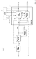
図1は、第1実施形態に係る移動体制御装置1000の概略構成図である。
<1.1: Configuration of mobile control device>
FIG. 1 is a schematic configuration diagram of a
移動体制御装置1000は、移動体(例えば、自律走行ロボットRbt1)(不図示)に搭載される装置である。
The mobile
移動体制御装置1000は、図1に示すように、観測取得部1と、ランドマーク検出部2と、候補領域取得部3と、状態推定部4と、記憶部5とを備える。
As shown in FIG. 1, the moving
なお、説明便宜のため、観測取得部1により取得される観測データD1は、移動体(ロボットRbt1)に搭載された距離センサー付き撮像装置(不図示)により撮像された画像(画像データ)と、距離センサー付き撮像装置により取得された距離画像(距離データ)であるものとして、以下、説明する。
For convenience of explanation, the observation data D1 acquired by the
観測取得部1は、移動体(ロボットRbt1)に搭載された距離センサー付き撮像装置(不図示)により取得されたデータを入力データDinとして入力とする。観測取得部1は、入力データDinから観測データD1、すなわち、画像(画像データ)D1_imgと距離画像(距離データ)D1_dとを取得し、取得した観測データD1をランドマーク検出部2と、状態推定部4の状態更新部41とに出力する。
ランドマーク検出部2は、観測取得部1から出力される観測データD1を入力する。ランドマーク検出部2は、観測データD1(画像データD1_imgおよび距離画像D1_d)から、ロボットRbt1からランドマークまでの距離および方向(角度)に関する情報を取得し、その取得した情報を含む信号を、ランドマーク検出信号LMtとして、候補領域取得部3と、状態推定部4の状態更新部41と、環境地図更新部42とに出力する。
The
The
候補領域取得部3は、ランドマーク検出部2から出力されるランドマーク検出信号LMtを入力する。候補領域取得部3は、ランドマーク検出信号LMtに基づいて、ロボットRbt1の現時刻の位置の候補位置を推定するための情報である自己位置候補情報Cdttを取得する。そして、候補領域取得部3は、取得した自己位置候補情報Cdttを状態推定部4の状態更新部41に出力する。
The candidate
状態推定部4は、図1に示すように、状態更新部41と、環境地図更新部42とを備える。
As shown in FIG. 1, the
状態更新部41は、観測取得部1から出力される観測データD1と、ランドマーク検出部2から出力されるランドマーク検出信号LMtと、候補領域取得部3から出力される自己位置候補情報Cdttと、移動体(ロボットRbt1)に対する制御入力データUtと、記憶部5から読み出した移動体(ロボットRbt1)の時刻t−1の内部状態データXt−1とを入力する。状態更新部41は、観測データD1、ランドマーク検出信号LMt、自己位置候補情報Cdtt、制御入力データUt、および、ロボットRbt1の時刻t−1の内部状態データXt−1基づいて、ロボットRbt1の内部状態を推定し、推定結果を移動体の現時刻tの内部状態データXtとして、取得する(内部状態データを更新する)。そして、状態更新部41は、取得した移動体の現時刻tの内部状態データXtを、状態推定部4から外部に出力するとともに、記憶部5に出力する。なお、状態推定部4から外部に出力された内部状態データXtは、移動体(自動走行ロボットRbt1)を制御するためのデータとして、例えば、移動体(自動走行ロボットRbt1)の全体を制御する機能部(全体制御部)(不図示)等により使用される。
また、状態更新部41は、現時刻tのロボットRbt1の位置に関する内部状態データXtを、環境地図更新部42に出力する。
Further, the
また、状態更新部41は、現時刻tのロボットRbt1に対する制御入力データUtを記憶部5に出力する。
Further, the
環境地図更新部42は、ランドマーク検出部2から出力されるランドマーク検出信号LMtと、記憶部5から読み出した時刻t−1の環境地図データmt−1と、状態更新部41から出力される現時刻tのロボットRbt1の内部状態データXtとを入力する。環境地図更新部42は、ランドマーク検出信号LMtから、検出されたランドマークについての情報を取得し、取得したランドマークの情報と、時刻t−1の環境地図データmt−1と、現時刻tのロボットRbt1の内部状態データXtとに基づいて、環境地図データを更新し、現時刻tの環境地図データmtを取得する。そして、環境地図更新部42は、更新した環境地図データmtを状態推定部4から外部に出力するとともに、記憶部5に出力する。なお、状態推定部4から外部に出力された環境地図データmtは、移動体(自動走行ロボットRbt1)を制御するためのデータとして、例えば、移動体(自動走行ロボットRbt1)の全体を制御する機能部(全体制御部)(不図示)等により使用される。
The environment
記憶部5は、状態推定部4の状態更新部41から出力される移動体の現時刻tの内部状態データXtと、環境地図データmtと、状態更新部41から出力される制御入力データUtとを入力し、記憶する。記憶部5に記憶されたデータは、状態推定部4により、所定のタイミングで読み出される。なお、記憶部5は、複数の時刻の内部状態データと、環境地図データとを記憶することができる。
The storage unit 5 includes the internal state data X t of the moving object at the current time t output from the
なお、現時刻tのデータとは、移動体制御装置1000において、処理対象となっている観測データD1から取得されたデータ(移動体の内部状態データXt、および、環境地図データmt)のことをいい、現時刻tの1つ前の時刻t−1のデータとは、現時刻tのデータを取得する1つ前に、移動体制御装置1000において取得されたデータ(移動体の内部状態データXt−1、および、環境地図データmt−1)のことをいう。つまり、現時刻tのk個前の時刻t−k(k:自然数)のデータとは、現時刻tのデータを取得するk個前に、移動体制御装置1000において取得されたデータ(移動体の内部状態データXt−k、および、環境地図データmt−k)のことをいう。
Note that the data at the current time t is the data (the internal state data X t of the mobile body and the environmental map data m t ) acquired from the observation data D1 that is the processing target in the mobile
また、上記データは、同期タイミングにより取得されるものであってもよいし、非同期タイミングにより取得されるものであってもよい。 The data may be acquired at a synchronous timing or may be acquired at an asynchronous timing.
<1.2:移動体制御装置の動作>
以上のように構成された移動体制御装置1000の動作について、以下、説明する。
<1.2: Operation of mobile control device>
The operation of the
なお、以下では、自律走行する移動体をロボットRbt1とし、ロボットRbt1に搭載された可視光用イメージセンサーと距離センサーとを備える撮像装置(不図示)により撮像された画像(撮像画像)と、距離画像(距離データ)とを入力データDinとし、ランドマークの情報により環境地図が生成される場合について、説明する。 In the following, an autonomously moving mobile body is defined as a robot Rbt1, and an image (captured image) captured by an imaging device (not shown) including a visible light image sensor and a distance sensor mounted on the robot Rbt1, and a distance A case where an image (distance data) is input data Din and an environmental map is generated based on landmark information will be described.
また、移動体制御装置1000により環境地図を生成するために、2つのランドマークを1組のセットとして、ロボットRbt1が移動する環境に設置されているものとする。また、1組のセットを構成するランドマークは、他の組のランドマークと識別できるように、例えば、カラーコードや特定の模様が付されている。これにより、発見されたランドマークがどの組(どのランドマーク・セット)に属するランドマークであるかを特定することができる。
Further, in order to generate an environment map by the moving
図2は、時刻tにおけるロボットRbt1の位置の候補となる点C1t、C2tと、1組のランドマークLM1AおよびランドマークLM1Bとの位置関係を示す図(上方から見た図)である。なお、図2において、図2に示すようにx軸、y軸をとるものとし、図2に「0」で示した位置を原点とする。なお、以下では、図2に示すように、説明便宜のため、2次元平面(xy平面)におけるロボットRbt1、ランドマークLM1A、LM1Bの位置関係に基づいて、移動体制御装置の処理について説明するが、これに限定されることはなく、移動体制御装置の処理については、3次元空間におけるロボットRbt1、ランドマークLM1A、LM1Bの位置関係に基づいて、実行されるものであってもよい。 FIG. 2 is a diagram (viewed from above) showing the positional relationship between the points C1 t and C2 t that are candidates for the position of the robot Rbt1 at time t and a set of landmarks LM1A and LM1B. In FIG. 2, the x-axis and the y-axis are taken as shown in FIG. 2, and the position indicated by “0” in FIG. 2 is the origin. In the following, as shown in FIG. 2, for convenience of explanation, the process of the mobile control device will be described based on the positional relationship between the robot Rbt1 and the landmarks LM1A and LM1B in a two-dimensional plane (xy plane). However, the present invention is not limited to this, and the processing of the mobile body control device may be executed based on the positional relationship between the robot Rbt1, the landmarks LM1A, and LM1B in the three-dimensional space.
図3は、時刻t+1におけるロボットRbt1の位置の候補となる点C1t+1、C2t+1と、1組のランドマークLM1AおよびランドマークLM1Bとの位置関係を示す図(上方から見た図)である。なお、図3においても、図2と同様に、図3に示すようにx軸、y軸をとるものとし、図3に「0」で示した位置を原点とする。 FIG. 3 is a diagram (viewed from above) showing the positional relationship between the points C1 t + 1 and C2 t + 1 that are candidates for the position of the robot Rbt1 at time t + 1 and a set of landmarks LM1A and LM1B. In FIG. 3, as in FIG. 2, the x axis and the y axis are taken as shown in FIG. 3, and the position indicated by “0” in FIG. 3 is the origin.
以下では、時刻tにおいて、図2に点C1tで示す位置に存在するロボットRbt1に対して、図3に示す矢印Dir1方向に移動させるための制御データが入力され、時刻t+1において、図3に点C1t+1で示す位置にロボットRbt1が移動する場合を一例として、説明する。
In the following, at time t, the robot Rbt1 present at a position shown in FIG. 2 two points C1 t, control data for moving the arrow Dir1 direction shown in FIG. 3 is input at
ここで、移動体制御装置1000において使用される、(1)ロボットRbt1の内部状態を示すデータ、および、(2)環境地図に関するデータについて、説明する。
Here, (1) data indicating the internal state of the robot Rbt1 and (2) data relating to the environment map used in the
(1.2.1:ロボットRbt1の内部状態データ)
移動体制御装置1000では、ロボットRbt1の内部状態を示すデータXtとして、時刻tにおけるロボットRbt1の位置および角度に関する内部状態データXtが設定される。
(1.2.1: Internal state data of robot Rbt1)
The
時刻tにおけるロボットRbt1の位置および角度に関する内部状態データXtは、3次元の状態ベクトルであり、
Xt=(x0t,y0t,θt)
x0t:時刻tにおけるロボットRbt1のx座標値の期待値
y0t:時刻tにおけるロボットRbt1のy座標値の期待値
θt:時刻tにおけるロボットRbt1のx軸正方向とのなす角度(ロボットRbt1の向き)の期待値
として表現される。
The internal state data X t regarding the position and angle of the robot Rbt1 at time t is a three-dimensional state vector,
X t = (x0 t , y0 t , θ t )
x0 t : Expected value of x-coordinate value of robot Rbt1 at time t y0 t : Expected value of y-coordinate value of robot Rbt1 at time t θ t : Angle formed by robot Rbt1 positive direction of robot Rbt1 at time t (robot Rbt1 ) Direction).
移動体制御装置1000では、ロボットRbt1の内部状態を推定するために、パーティクルフィルタ(モンテカルロ近似)を用いるものとする。
In the moving
つまり、パーティクルフィルタ処理では、時刻t−1の状態ベクトルXt−1の事後確率分布を現時刻tの状態ベクトルXtの事前確率分布とし、現時刻tの状態ベクトルXtの事前確率分布から予測処理により現時刻tの状態ベクトルXtの予測確率分布を取得する。そして、取得した予測確率分布と実際の観測データ(現時刻tの観測データ)とに基づいて、尤度を算出する。そして、算出した尤度に比例する割合で、粒子(パーティクル)を復元抽出する。このように処理することで、ロボットRbt1の内部状態を推定することができる。 That is, the particle filtering, the posterior probability distribution of the state vector X t-1 at time t-1 and prior probability distribution of the state vector X t of the current time t, the prior probability distribution of the state vector X t of the current time t obtaining a prediction probability distribution of the state vector X t of the current time t by the prediction process. Then, the likelihood is calculated based on the acquired prediction probability distribution and the actual observation data (observation data at the current time t). Then, particles (particles) are restored and extracted at a rate proportional to the calculated likelihood. By processing in this way, the internal state of the robot Rbt1 can be estimated.
以上のように、移動体制御装置1000では、ロボットRbt1の内部状態を示すデータXtが設定される。
As described above, the
(1.2.2:環境地図に関するデータ)
移動体制御装置1000では、環境地図に関するデータとして、時刻tにおける環境地図データmtが設定される。
(1.2.2: Data related to environmental maps)
In the mobile
環境地図データmtは、ランドマークの情報により構成される。ロボットRbt1によりランドマークが発見された場合、発見されたランドマークの情報は、環境地図データmtに追加される。 Environment map data m t is constituted by information of the landmark. If the landmark has been discovered by the robot Rbt1, information of the discovered land mark is added to the environment map data m t.
時刻tにおける環境地図データmtは、移動体制御装置1000において、以下のように、設定される。
mt=[LM1APt,LM1BPt,....,LMkAPt,LMkBPt]
k:自然数
LMkAPtは、時刻tにおけるk組目のランドマークセットを構成する一方のランドマークの位置に関する内部状態データであり、LMkBPtは、時刻tにおけるk組目のランドマークセットを構成する他方のランドマークの位置に関する内部状態データである。なお、1組のランドマークセットは、2つのランドマークから構成される。
The environmental map data m t at time t is set in the
m t = [LM1AP t , LM1BP t ,. . . . , LMkAP t , LMkBP t ]
k: Natural number LMkAP t is internal state data regarding the position of one landmark constituting the k-th landmark set at time t, and LMkBP t constitutes the k-th landmark set at time t. This is internal state data relating to the position of the other landmark. A set of landmarks is composed of two landmarks.
つまり、移動体制御装置1000では、k組のランドマークセットに含まれる2×k個のランドマークについての内部状態データの集合が、時刻tにおける環境地図データmtとして、設定される。
That is, the
図2の場合において、環境地図データmtは、1組のランドマークセットを構成する2つのランドマークLM1A、LM1Bの情報により構成される。図2の場合、環境地図データmtは、
mt=[LM1APt,LM1BPt]
である。
In the case of Figure 2, the environment map data m t is two landmarks LM1A constituting a set of landmark set, constituted by information LM1B. For Figure 2, the environment map data m t is
m t = [LM1AP t , LM1BP t ]
It is.
なお、ランドマークLM1A、LM1Bの情報(位置に関する内部状態データ)LM1APt、LM1BPtは、例えば、以下のように設定される。
ランドマークLM1A:
LM1APt=(d1At,θ1At)
d1At:ロボットRbt1からランドマークLM1Aまでの距離
θ1At:平面視において、ロボットRbt1からランドマークLM1Aへ引いた直線とx軸とのなす角度
ランドマークLM1B:
LM1BPt=(d1Bt,θ1Bt)
d1Bt:ロボットRbt1からランドマークLM1Bまでの距離
θ1Bt:平面視において、ロボットRbt1からランドマークLM1Bへ引いた直線とx軸とのなす角度
なお、以下では、説明便宜のため、図2、図3に示すように、移動体制御装置1000を搭載したロボットRbt1が1つのランドマークセットに含まれる2つのランドマークLMA1、LMB1により、ロボットRbt1の内部状態データ、および、環境地図データが取得される場合について、説明する。
Note that the landmarks LM1A and LM1B information (positional internal state data) LM1AP t and LM1BP t are set as follows, for example.
Landmark LM1A:
LM1AP t = (d1A t , θ1A t )
d1A t : Distance from the robot Rbt1 to the landmark LM1A θ1A t : Angle landmark LM1B formed by a straight line drawn from the robot Rbt1 to the landmark LM1A and the x axis in plan view:
LM1BP t = (d1B t , θ1B t )
d1B t : Distance from the robot Rbt1 to the landmark LM1B θ1B t : Angle formed by the straight line drawn from the robot Rbt1 to the landmark LM1B and the x-axis in plan view Note that, for convenience of explanation, FIG. As shown in FIG. 3, the internal state data and environmental map data of the robot Rbt1 are acquired by the two landmarks LMA1 and LMB1 included in one landmark set of the robot Rbt1 on which the mobile
(1.2.3:具体的処理)
次に、移動体制御装置1000の具体的処理について、説明する。
(1.2.3: Specific processing)
Next, specific processing of the
(時刻tの処理):
時刻tにおいて、ロボットRbt1、ランドマークLM1A、LM1Bの状態は、図2に示す状態である。なお、移動体制御装置1000に搭載された距離センサー付き撮像装置では、図2に示す領域ARcpの撮像画像(画像データ)と、距離画像(距離データ)とが取得される。
(Processing at time t):
At time t, the states of the robot Rbt1, the landmarks LM1A, and LM1B are the states shown in FIG. Incidentally, the distance sensor with an imaging device mounted on the
観測取得部1は、移動体制御装置1000に搭載された距離センサー付き撮像装置からの入力データDinから観測データD1、すなわち、領域ARcpの画像(画像データ)D1_imgと距離画像(距離データ)D1_dとを取得し、取得した観測データD1をランドマーク検出部2と、状態推定部4の状態更新部41とに出力する。
ランドマーク検出部2では、観測データD1(画像データD1_imgおよび距離画像D1_d)から、ロボットRbt1からランドマークLM1A、LM1Bまでの距離および方向(角度)に関する情報が取得される。具体的には、以下のデータLM1APt、LM1BPtが、ランドマーク検出部2により取得される。
ランドマークLM1A:
LM1APt=(d1At,θ1At)
d1At:ロボットRbt1からランドマークLM1Aまでの距離
θ1At:平面視において、ロボットRbt1からランドマークLM1Aへ引いた直線とx軸とのなす角度
ランドマークLM1B:
LM1BPt=(d1Bt,θ1Bt)
d1Bt:ロボットRbt1からランドマークLM1Bまでの距離
θ1Bt:平面視において、ロボットRbt1からランドマークLM1Bへ引いた直線とx軸とのなす角度
上記により取得されたランドマークLM1A、LM1BについてのデータLM1APt、LM1BPtを含めた信号が、ランドマーク検出信号LMtとして、ランドマーク検出部2から、候補領域取得部3、状態推定部4の状態更新部41、および、環境地図更新部42に出力される。
In the
Landmark LM1A:
LM1AP t = (d1A t , θ1A t )
d1A t : Distance from the robot Rbt1 to the landmark LM1A θ1A t : Angle landmark LM1B formed by a straight line drawn from the robot Rbt1 to the landmark LM1A and the x axis in plan view:
LM1BP t = (d1B t , θ1B t )
d1B t : Distance from the robot Rbt1 to the landmark LM1B θ1B t : Angle formed by the straight line drawn from the robot Rbt1 to the landmark LM1B and the x axis in plan view Data LM1AP for the landmarks LM1A and LM1B acquired as described above A signal including t and LM1BP t is output as a landmark detection signal LM t from the
候補領域取得部3では、ランドマーク検出信号LMtに基づいて、ロボットRbt1の現時刻tの位置の候補位置を推定するための情報が取得される。
With candidate
具体的には、候補領域取得部3は、図2に示すように、(1)点LM1Aを中心とし、半径をロボットRbt1からランドマークLM1Aまでの距離d1Atとする円と、(2)点LM1Bを中心とし、半径をロボットRbt1からランドマークLM1Bまでの距離d1Btとする円との2つの交点C1t、C2tとを求める。そして、候補領域取得部3は、求めた2つの交点C1t、C2tに関する情報(交点C1t、C2tを特定するための情報)を自己位置候補情報Cdttとして、状態推定部4の状態更新部41に出力する。
Specifically, the candidate
なお、候補領域取得部3での処理において、誤差やランドマーク位置の推定精度(ランドマークについての内部状態データの精度)を考慮して、候補領域取得部3は、求めた2つの交点C1t、C2tを含む所定の面積を有する領域に関する情報を、自己位置候補情報Cdttとして、状態推定部4の状態更新部41に出力するようにしてもよい。
In the processing in the candidate
状態推定部4の状態更新部41は、観測データD1、ランドマーク検出信号LMt、自己位置候補情報Cdtt、制御入力データUt、および、ロボットRbt1の時刻t−1の内部状態データXt−1基づいて、ロボットRbt1の内部状態を推定し、推定結果をロボットRbt1の現時刻tの内部状態データXtとして、取得する(内部状態データを更新する)。
The
具体的には、自己位置候補情報Cdttから、ロボットRbt1の自己位置の2つの候補点である点C1t、C2tのうちのどちらか1つの点を、時刻tのロボットRbt1の位置であると推定する。ここでは、状態更新部41により、点C1tが、時刻tのロボットRbt1の位置であると推定されたものとして、以下、説明する。
Specifically, from the self-position candidate information Cdt t , one of the two candidate points C1 t and C2 t of the self-position of the robot Rbt1 is the position of the robot Rbt1 at time t. Estimated. Here, the following description will be made assuming that the
状態更新部41により取得された時刻tのロボットRbt1の内部状態データXtは、状態更新部41から記憶部5に出力され、記憶部5で記憶される。
Internal state data X t robot Rbt1 the obtained time t by the
環境地図更新部42は、ランドマーク検出部2から出力されるランドマーク検出信号LMtから、検出されたランドマークについての情報を取得し、取得したランドマークの情報と、時刻t−1の環境地図データmt−1と、現時刻tのロボットRbt1の内部状態データXtとに基づいて、環境地図データを更新し、現時刻tの環境地図データmtを取得する。
The environment
具体的には、時刻tにおけるランドマークLM1Aのxy平面上の位置座標を(x1At,y1At)とし、時刻tにおけるランドマークLM1Bのxy平面上の位置座標を(x1Bt,y1Bt)とすると、環境地図更新部42は、
x1At=x0t+d1At×cos(θ1At)
y1At=y0t+d1At×sin(θ1At)
x1Bt=x0t+d1Bt×cos(θ1Bt)
y1Bt=y0t+d1Bt×sin(θ1Bt)
により、時刻tにおけるランドマークLM1A、LM1Bのxy平面上の位置座標(位置情報)を取得する。
Specifically, the position coordinate on the xy plane of the landmark LM1A at time t is (x1A t , y1A t ), and the position coordinate on the xy plane of the landmark LM1B at time t is (x1B t , y1B t ). Then, the environmental
x1A t = x0 t + d1A t × cos (θ1A t )
y1A t = y0 t + d1A t × sin (θ1A t )
x1B t = x0 t + d1B t × cos (θ1B t )
y1B t = y0 t + d1B t × sin (θ1B t )
Thus, the position coordinates (position information) on the xy plane of the landmarks LM1A and LM1B at time t are acquired.
そして、環境地図更新部42は、上記により取得したデータにより、環境地図データmtを更新する。
The environment
また、時刻tにおいて、ロボットRbt1には、制御入力Utが入力される。なお、制御入力Utは、図3に矢印Dir1で示す方向にロボットRbt1を移動させるための制御入力データであるとして、以下、説明する。
At time t, a control input U t is input to the robot Rbt1. The control input U t will be described below assuming that the control input U t is control input data for moving the
(時刻t+1の処理):
時刻t+1において、ロボットRbt1は、時刻tの制御入力データUtにより、図3に点C1t+1で示す位置、あるいは、図3に点C2_NGt+1で示す位置に移動していると予測される。
(Processing at time t + 1):
At
観測取得部1は、移動体制御装置1000に搭載された距離センサー付き撮像装置からの入力データDinから観測データD1、すなわち、領域ARcpの画像(画像データ)D1_imgと距離画像(距離データ)D1_dとを取得し、取得した観測データD1をランドマーク検出部2と、状態推定部4の状態更新部41とに出力する。
ランドマーク検出部2では、観測データD1(画像データD1_imgおよび距離画像D1_d)から、ロボットRbt1からランドマークLM1A、LM1Bまでの距離および方向(角度)に関する情報が取得される。具体的には、以下のデータLM1APt、LM1BPtが、ランドマーク検出部2により取得される。
ランドマークLM1A:
LM1APt+1=(d1At+1,θ1At+1)
d1At+1:ロボットRbt1からランドマークLM1Aまでの距離
θ1At+1:平面視において、ロボットRbt1からランドマークLM1Aへ引いた直線とx軸とのなす角度
ランドマークLM1B:
LM1BPt+1=(d1Bt+1,θ1Bt+1)
d1Bt+1:ロボットRbt1からランドマークLM1Bまでの距離
θ1Bt+1:平面視において、ロボットRbt1からランドマークLM1Bへ引いた直線とx軸とのなす角度
上記により取得されたランドマークLM1A、LM1BについてのデータLM1APt+1、LM1BPt+1を含めた信号が、ランドマーク検出信号LMt+1として、ランドマーク検出部2から、候補領域取得部3、状態推定部4の状態更新部41、および、環境地図更新部42に出力される。
In the
Landmark LM1A:
LM1AP t + 1 = (d1A t + 1 , θ1A t + 1 )
d1A t + 1 : Distance from the robot Rbt1 to the landmark LM1A θ1A t + 1 : Angle landmark LM1B formed by the straight line drawn from the robot Rbt1 to the landmark LM1A and the x axis in plan view:
LM1BP t + 1 = (d1B t + 1 , θ1B t + 1 )
d1B t + 1 : Distance from the robot Rbt1 to the landmark LM1B θ1B t + 1 : Angle between the straight line drawn from the robot Rbt1 to the landmark LM1B and the x axis in plan view Data LM1AP on the landmarks LM1A and LM1B acquired as described above Signals including t + 1 and LM1BP t + 1 are output as the landmark detection signal LM t + 1 from the
候補領域取得部3では、ランドマーク検出信号LMt+1に基づいて、ロボットRbt1の現時刻tの位置の候補位置を推定するための情報が取得される。
The candidate
具体的には、候補領域取得部3は、図3に示すように、(1)点LM1Aを中心とし、半径をロボットRbt1からランドマークLM1Aまでの距離d1At+1とする円と、(2)点LM1Bを中心とし、半径をロボットRbt1からランドマークLM1Bまでの距離d1Bt+1とする円との2つの交点C1t+1、C2t+1とを求める。そして、候補領域取得部3は、求めた2つの交点C1t+1、C2t+1に関する情報(交点C1t+1、C2t+1を特定するための情報)を自己位置候補情報Cdtt+1として、状態推定部4の状態更新部41に出力する。
Specifically, as shown in FIG. 3, the candidate
なお、候補領域取得部3での処理において、誤差やランドマーク位置の推定精度(ランドマークについての内部状態データの精度)を考慮して、候補領域取得部3は、求めた2つの交点C1t+1、C2t+1を含む所定の面積を有する領域に関する情報を、自己位置候補情報Cdtt+1として、状態推定部4の状態更新部41に出力するようにしてもよい。
In the processing in the candidate
状態推定部4の状態更新部41は、観測データD1、ランドマーク検出信号LMt+1、自己位置候補情報Cdtt+1、制御入力データUt+1、および、ロボットRbt1の時刻tの内部状態データXt基づいて、ロボットRbt1の内部状態を推定し、推定結果をロボットRbt1の現時刻t+1の内部状態データXt+1として、取得する(内部状態データを更新する)。
The
具体的には、自己位置候補情報Cdtt+1から、ロボットRbt1の自己位置の2つの候補点である点C1t+1、C2t+1のうちのどちらか1つの点を、時刻tのロボットRbt1の位置であると推定する。 Specifically, from the self-position candidate information Cdt t + 1 , one of the points C1 t + 1 and C2 t + 1 which are two candidate points of the self-position of the robot Rbt1 is the position of the robot Rbt1 at time t. Estimated.
移動体制御装置1000は、(1)時刻tのロボットRbt1の位置の2つの候補点として、点C1t、点C2tを取得し、(2)時刻t+1のロボットRbt1の位置の2つの候補点として、点C1t+1、点C2t+1を取得している。そして、時刻tのロボットRbt1への制御入力Utが、ロボットRbt1を図3の矢印Dir1への方向への移動をするためのデータである。
The
状態更新部41は、時刻tのロボットRbt1への制御入力Utと、移動体制御装置1000により推定された時刻tのロボットRbt1の位置の2つの候補点C1t、C2tとから、時刻tにおいて、ロボットRbt1が、図3の点C1t+1、あるいは、点C2_NGt+1のいずれかに存在すると予測する(予測処理1)。
The
また、状態更新部41は、時刻t+1の実際の観測より、時刻t+1において、ロボットRbt1とLM1Aとの距離は、d1At+1であり、ロボットRbt1とLM2Aとの距離は、d2At+1であるので、時刻t+1の実際の観測から求められる時刻t+1のロボットRbt1の位置は、候補点C1t+1、あるいは、候補点C2t+1であると予測する(予測処理2)。
Further, from the actual observation at
つまり、状態更新部41は、上記予測処理1、および、予測処理2の両方において、時刻t+1のロボットRbt1の位置の候補点であると予測された点C1t+1を、時刻t+1のロボットRbt1の位置であると推定する。そして、状態更新部41は、時刻t+1のロボットRbt1の位置についての内部状態データ(座標データ(x0At+1,y0At+1))を、点C1t+1の座標情報により更新する。
That is, the
以上のようにして、状態更新部41により取得された時刻t+1のロボットRbt1の内部状態データXt+1は、状態更新部41から記憶部5に出力され、記憶部5で記憶される。
As described above, the internal state data X t + 1 of the obtained time t + 1 of the robot Rbt1 the
環境地図更新部42は、ランドマーク検出部2から出力されるランドマーク検出信号LMtから、検出されたランドマークについての情報を取得し、取得したランドマークの情報と、時刻tの環境地図データmtと、現時刻t+1のロボットRbt1の内部状態データXt+1とに基づいて、環境地図データを更新し、現時刻t+1の環境地図データmt+1を取得する。
The environment
具体的には、時刻t+1におけるランドマークLM1Aのxy平面上の位置座標を(x1At+1,y1At+1)とし、時刻t+1におけるランドマークLM1Bのxy平面上の位置座標を(x1Bt+1,y1Bt+1)とすると、環境地図更新部42は、
x1At+1=x0t+1+d1At+1×cos(θ1At+1)
y1At+1=y0t+1+d1At+1×sin(θ1At+1)
x1Bt+1=x0t+1+d1Bt+1×cos(θ1Bt+1)
y1Bt+1=y0t+1+d1Bt+1×sin(θ1Bt+1)
により、時刻tにおけるランドマークLM1A、LM1Bのxy平面上の位置座標(位置情報)を取得する。
Specifically, the position coordinate on the xy plane of the landmark LM1A at time t + 1 is (x1A t + 1 , y1A t + 1 ), and the position coordinate on the xy plane of the landmark LM1B at time t + 1 is (x1B t + 1 , y1B t + 1 ). Then, the environmental
x1A t + 1 = x0 t + 1 + d1A t + 1 × cos (θ1A t + 1 )
y1A t + 1 = y0 t + 1 + d1A t + 1 × sin (θ1A t + 1 )
x1B t + 1 = x0 t + 1 + d1B t + 1 × cos (θ1B t + 1 )
y1B t + 1 = y0 t + 1 + d1B t + 1 × sin (θ1B t + 1 )
Thus, the position coordinates (position information) on the xy plane of the landmarks LM1A and LM1B at time t are acquired.
そして、環境地図更新部42は、上記により取得したデータにより、環境地図データmt+1を更新する。
The environment
(時刻t+2以降の処理):
時刻t+2以降において、上記と同様の処理が繰り返し実行される。
(Process after time t + 2):
After
このように、移動体制御装置1000では、2つのランドマークを1組とするランドマークセットを用いて、ロボットRbt1から2つのランドマークまでの距離を測定することで、ロボットRbt1の位置を少ない候補点(上記では2点)に絞り、高速かつ高精度に、ロボットRbt1の位置情報を含む内部状態データを推定することができる。例えば、上記で示した例では、移動体制御装置1000において、時刻t、時刻t+1の2回の推定処理を実行することで、ロボットRbt1の位置を1点に絞り込むことができる。
As described above, the mobile
以上のように処理することで、移動体制御装置1000では、ランドマークの情報から、移動体(ロボットRbt1)の位置を精度良く推定し、高精度な状態推定処理を高速かつ適切に実行することができる。その結果、移動体制御装置1000では、移動体(ロボットRbt1)の制御を適切に行うことができる。
By performing the processing as described above, the mobile
さらに、移動体制御装置1000では、上記の通り、1つのランドマークセットに含まれる2つのランドマークと、ロボットRbt1との距離を取得するだけで、ロボットRbt1の位置を高速かつ高精度に推定することができる。このため、移動体制御装置1000では、多くの内部状態変数を用いた複雑な処理をすることなく、少ない演算量で推定処理を実現することができる。
Furthermore, as described above, the
[第2実施形態]
次に、第2実施形態について、説明する。
[Second Embodiment]
Next, a second embodiment will be described.
第2実施形態において、第1実施形態と同様の部分については、同一符号を付し、詳細な説明を省略する。 In the second embodiment, portions similar to those in the first embodiment are denoted by the same reference numerals, and detailed description thereof is omitted.
図4は、第2実施形態に係る移動体制御装置2000の概略構成図である。
FIG. 4 is a schematic configuration diagram of a
第2実施形態の移動体制御装置2000では、図4に示すように、第1実施形態の移動体制御装置1000において、ランドマーク検出部2をランドマーク検出部2Aに置換し、候補領域取得部3を候補領域取得部3Aに置換した構成を有している。
In the
ランドマーク検出部2Aは、ランドマーク検出部2の機能に加えて、時刻tにおいて、ロボットRbt1に搭載された距離センサー付き撮像装置(不図示)により撮像された画像(画像データ)からランドマークを含む画像領域を抽出し、抽出した画像を画像D1_imgとして、候補領域取得部3に出力する。また、ランドマーク検出部2Aは、ランドマーク検出信号LMtを、候補領域取得部3A、状態更新部41、および、環境地図更新部42に出力する。
In addition to the function of the
候補領域取得部3Aは、図4に示すように、ランドマーク検出部2Aから出力されるランドマーク検出信号LMtおよび画像D1_imgと、ランドマークパターン情報LM_ptnとを入力する。ランドマークパターン情報LM_ptnは、予め設定されている情報であり、ロボットRbt1が移動する環境に設置されているランドマークの表面に付されているパターン(色、模様等)についての情報である。候補領域取得部3は、ランドマークパターン情報LM_ptnと、画像D1_imgとに基づいて、ロボットRbt1の現時刻の位置の候補位置を推定するための情報である自己位置候補情報Cdttを取得する。そして、候補領域取得部3Aは、取得した自己位置候補情報Cdttを状態推定部4の状態更新部41に出力する。
Candidate
本実施形態において使用されるランドマーク(一例)は、細長い円筒形状であり、ランドマークの表面が、(1)第1パターンを付された第1パターン領域と、(2)第2パターンを付された第2パターン領域と、の2つの領域からなる。そして、ランドマークを設置した状態の平面視において、一方の半円に相当する円周上の表面が第1パターン領域であり、他方の半円に相当する円周上の表面が第2パターン領域であるものとする。 A landmark (one example) used in the present embodiment has an elongated cylindrical shape, and the surface of the landmark is (1) a first pattern region to which a first pattern is applied, and (2) a second pattern. The second pattern region is formed into two regions. In plan view with the landmarks installed, the surface on the circumference corresponding to one semicircle is the first pattern area, and the surface on the circumference corresponding to the other semicircle is the second pattern area. Suppose that
なお、ランドマークの形状および表面のパターンは、上記に限定されることはない。移動体制御装置2000によりランドマークを発見したときに、当該ランドマークの形状、および/または、パターンを認識(特定)することで、移動体(ロボットRbt1)と、ランドマークとの位置関係(ランドマークがどの方向から観測されたかを知る手掛かりになる情報)を取得できるものであれば、ランドマークの形状および/またはパターンは、他のものであってもよい。
The shape of the landmark and the pattern on the surface are not limited to the above. When a landmark is discovered by the moving
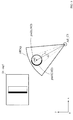
≪図5の場合≫
図5は、時刻tにおけるロボットRbt1の位置の候補となる領域AR_C1と、本実施形態のランドマークLM2との位置関係を示す図(上方から見た図)と、時刻tにおいて、ロボットRbt1に搭載された距離センサー付き撮像装置(不図示)により撮像された画像(画像データ)D1_img1とを模式的に示した図である。なお、画像D1_img1は、ランドマーク検出部2Aから候補領域取得部3Aに出力される画像(画像データ)である。
<< In the case of FIG. 5 >>
FIG. 5 is a diagram showing a positional relationship between the area AR_C1 that is a candidate position of the robot Rbt1 at time t and the landmark LM2 of this embodiment (viewed from above), and is mounted on the robot Rbt1 at time t. It is the figure which showed typically the image (image data) D1_img1 imaged with the imaging device with a distance sensor (not shown). Note that the image D1_img1 is an image (image data) output from the
候補領域取得部3Aは、ランドマークLM2のランドマークパターン情報LM_ptnに基づいて、図5に示す画像D1_img1を解析する。具体的には、候補領域取得部3Aは、ランドマークLM2のランドマークパターン情報LM_ptnから、ランドマークLM2の平面視において一方の半円に相当する円周上の表面が第1パターン領域(黒色一色のパターン)(図5において、ptn1(LM2)と表記している領域)であり、ランドマークLM2の平面視において他方の半円に相当する円周上の表面が第2パターン領域(白色一色のパターン)(図5において、ptn2(LM2)と表記している領域)であることを認識する。
Candidate
そして、候補領域取得部3Aは、画像D1_img1上において、ランドマークの中央付近に、第1パターン領域(黒色一色のパターン)と第2パターン領域(白色一色のパターン)が存在し、かつ、左側に第1パターン領域(黒色一色のパターン)が存在し、右側に第2パターン領域(白色一色のパターン)が存在することを認識する。そして、候補領域取得部3Aは、上記画像解析結果に基づいて、画像D1_img1が撮像された位置の候補領域AR_C1を求める。つまり、図5に示すように、平面視において、ランドマークLM2の位置(中心点)から、ランドマークLM2の第1パターン領域ptn1(LM2)と第2パターン領域ptn2(LM2)との境界点を通る直線のy軸負方向に、距離d2だけ離れた領域が、時刻tのロボットRbt1の位置の候補領域AR_C1であると判定する。なお、候補領域取得部3Aは、ランドマーク検出信号LMtから、ランドマークLM2とロボットRbt1との距離d2を取得する。
Then, the candidate
候補領域取得部3Aは、上記のようにして取得した時刻tのロボットRbt1の位置の候補領域AR_C1についての情報を、自己位置候補情報Cdttに含めて、状態更新部41に出力する。
The candidate
状態更新部41は、自己位置候補情報Cdttから、時刻tのロボットRbt1の位置が、候補領域AR_C1である可能性が高いと判定し、ロボットRbt1の位置に関する内部状態データを更新する。
The
≪図6の場合≫
図6は、時刻tにおけるロボットRbt1の位置の候補となる領域AR_C2と、本実施形態のランドマークLM2との位置関係を示す図(上方から見た図)と、時刻tにおいて、ロボットRbt1に搭載された距離センサー付き撮像装置(不図示)により撮像された画像(画像データ)D1_img2とを模式的に示した図である。なお、画像D1_img2は、ランドマーク検出部2Aから候補領域取得部3Aに出力される画像(画像データ)である。
<< In the case of FIG. 6 >>
FIG. 6 is a diagram showing a positional relationship between the area AR_C2 that is a candidate position of the robot Rbt1 at time t and the landmark LM2 of this embodiment (viewed from above), and is mounted on the robot Rbt1 at time t. It is the figure which showed typically the image (image data) D1_img2 imaged with the imaging device with a distance sensor (not shown). Note that the image D1_img2 is an image (image data) output from the
候補領域取得部3Aは、ランドマークLM2のランドマークパターン情報LM_ptnに基づいて、図6に示す画像D1_img1を解析する。具体的には、候補領域取得部3Aは、ランドマークLM2のランドマークパターン情報LM_ptnから、ランドマークLM2の平面視において一方の半円に相当する円周上の表面が第1パターン領域(黒色一色のパターン)(図6において、ptn1(LM2)と表記している領域)であり、ランドマークLM2の平面視において他方の半円に相当する円周上の表面が第2パターン領域(白色一色のパターン)(図6において、ptn2(LM2)と表記している領域)であることを認識する。
Candidate
そして、候補領域取得部3Aは、画像D1_img2上において、ランドマークの中央付近に、第1パターン領域(黒色一色のパターン)と第2パターン領域(白色一色のパターン)が存在し、かつ、右側に第1パターン領域(黒色一色のパターン)が存在し、左側に第2パターン領域(白色一色のパターン)が存在することを認識する。そして、候補領域取得部3Aは、上記画像解析結果に基づいて、画像D1_img2が撮像された位置の候補領域AR_C2を求める。つまり、図6に示すように、平面視において、ランドマークLM2の位置(中心点)から、ランドマークLM2の第1パターン領域ptn1(LM2)と第2パターン領域ptn2(LM2)との境界点を通る直線のy軸正方向に、距離d2だけ離れた領域が、時刻tのロボットRbt1の位置の候補領域AR_C2であると判定する。なお、候補領域取得部3Aは、ランドマーク検出信号LMtから、ランドマークLM2とロボットRbt1との距離d2を取得する。
Then, the candidate
候補領域取得部3Aは、上記のようにして取得した時刻tのロボットRbt1の位置の候補領域AR_C2についての情報を、自己位置候補情報Cdttに含めて、状態更新部41に出力する。
The candidate
状態更新部41は、自己位置候補情報Cdttから、時刻tのロボットRbt1の位置が、候補領域AR_C2である可能性が高いと判定し、ロボットRbt1の位置に関する内部状態データを更新する。
The
≪図7の場合≫
図7は、時刻tにおけるロボットRbt1の位置の候補となる領域AR_C3と、本実施形態のランドマークLM2との位置関係を示す図(上方から見た図)と、時刻tにおいて、ロボットRbt1に搭載された距離センサー付き撮像装置(不図示)により撮像された画像(画像データ)D1_img3とを模式的に示した図である。なお、画像D1_img3は、ランドマーク検出部2Aから候補領域取得部3Aに出力される画像(画像データ)である。
<< In the case of FIG. 7 >>
FIG. 7 is a diagram (viewed from above) showing the positional relationship between the area AR_C3 that is a candidate position of the robot Rbt1 at time t and the landmark LM2 of this embodiment, and is mounted on the robot Rbt1 at time t. It is the figure which showed typically the image (image data) D1_img3 imaged with the imaging device with a distance sensor (not shown). Note that the image D1_img3 is an image (image data) output from the
候補領域取得部3Aは、ランドマークLM2のランドマークパターン情報LM_ptnに基づいて、図7に示す画像D1_img3を解析する。具体的には、候補領域取得部3Aは、ランドマークLM2のランドマークパターン情報LM_ptnから、ランドマークLM2の平面視において一方の半円に相当する円周上の表面が第1パターン領域(黒色一色のパターン)(図7において、ptn1(LM2)と表記している領域)であり、ランドマークLM2の平面視において他方の半円に相当する円周上の表面が第2パターン領域(白色一色のパターン)(図7において、ptn2(LM2)と表記している領域)であることを認識する。
Candidate
そして、候補領域取得部3Aは、画像D1_img3上において、ランドマークLM2の第2パターン領域(白色一色のパターン)のみが存在することを認識する。そして、候補領域取得部3Aは、上記画像解析結果に基づいて、画像D1_img3が撮像された位置の候補領域AR_C3を求める。つまり、図7に示すように、平面視において、ランドマークLM2の位置(中心点)から、ランドマークLM2の第2パターン領域ptn2(LM2)の中央付近の点を通る直線のx軸正方向に、距離d2だけ離れた領域が、時刻tのロボットRbt1の位置の候補領域AR_C3であると判定する。なお、候補領域取得部3Aは、ランドマーク検出信号LMtから、ランドマークLM2とロボットRbt1との距離d2を取得する。
Then, the candidate
候補領域取得部3Aは、上記のようにして取得した時刻tのロボットRbt1の位置の候補領域AR_C3についての情報を、自己位置候補情報Cdttに含めて、状態更新部41に出力する。
The candidate
状態更新部41は、自己位置候補情報Cdttから、時刻tのロボットRbt1の位置が、候補領域AR_C3である可能性が高いと判定し、ロボットRbt1の位置に関する内部状態データを更新する。
The
≪図8の場合≫
図8は、時刻tにおけるロボットRbt1の位置の候補となる領域AR_C4と、本実施形態のランドマークLM2との位置関係を示す図(上方から見た図)と、時刻tにおいて、ロボットRbt1に搭載された距離センサー付き撮像装置(不図示)により撮像された画像(画像データ)D1_img4とを模式的に示した図である。なお、画像D1_img4は、ランドマーク検出部2Aから候補領域取得部3Aに出力される画像(画像データ)である。
<< In the case of FIG. 8 >>
FIG. 8 is a diagram showing a positional relationship between the area AR_C4 that is a candidate position of the robot Rbt1 at time t and the landmark LM2 of this embodiment (viewed from above), and is mounted on the robot Rbt1 at time t. It is the figure which showed typically the image (image data) D1_img4 imaged with the image pick-up device with a distance sensor (not shown). Note that the image D1_img4 is an image (image data) output from the
候補領域取得部3Aは、ランドマークLM2のランドマークパターン情報LM_ptnに基づいて、図8に示す画像D1_img4を解析する。具体的には、候補領域取得部3Aは、ランドマークLM2のランドマークパターン情報LM_ptnから、ランドマークLM2の平面視において一方の半円に相当する円周上の表面が第1パターン領域(黒色一色のパターン)(図8において、ptn1(LM2)と表記している領域)であり、ランドマークLM2の平面視において他方の半円に相当する円周上の表面が第2パターン領域(白色一色のパターン)(図8において、ptn2(LM2)と表記している領域)であることを認識する。
The candidate
そして、候補領域取得部3Aは、画像D1_img4上において、ランドマークの中央付近に、第1パターン領域(黒色一色のパターン)のみが存在することを認識する。そして、候補領域取得部3Aは、上記画像解析結果に基づいて、画像D1_img4が撮像された位置の候補領域AR_C4を求める。つまり、図8に示すように、平面視において、ランドマークLM2の位置(中心点)から、ランドマークLM2の第2パターン領域ptn2(LM2)の中央付近の点を通る直線のx軸負方向に、距離d2だけ離れた領域が、時刻tのロボットRbt1の位置の候補領域AR_C4であると判定する。なお、候補領域取得部3Aは、ランドマーク検出信号LMtから、ランドマークLM2とロボットRbt1との距離d2を取得する。
Then, the candidate
候補領域取得部3Aは、上記のようにして取得した時刻tのロボットRbt1の位置の候補領域AR_C4についての情報を、自己位置候補情報Cdttに含めて、状態更新部41に出力する。
The candidate
状態更新部41は、自己位置候補情報Cdttから、時刻tのロボットRbt1の位置が、候補領域AR_C4である可能性が高いと判定し、ロボットRbt1の位置に関する内部状態データを更新する。
The
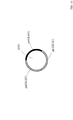
≪図9の場合≫
図9は、は、時刻tにおけるロボットRbt1の位置の候補となる領域AR_C5と、本実施形態のランドマークLM2との位置関係を示す図(上方から見た図)と、時刻tにおいて、ロボットRbt1に搭載された距離センサー付き撮像装置(不図示)により撮像された画像(画像データ)D1_img5とを模式的に示した図である。なお、画像D1_img5は、ランドマーク検出部2Aから候補領域取得部3Aに出力される画像(画像データ)である。
<< In the case of FIG. 9 >>
FIG. 9 is a diagram (viewed from above) showing the positional relationship between the area AR_C5 that is a candidate position of the robot Rbt1 at time t and the landmark LM2 of this embodiment, and the robot Rbt1 at time t. It is the figure which showed typically the image (image data) D1_img5 imaged with the imaging device with a distance sensor (not shown) mounted in FIG. Note that the image D1_img5 is an image (image data) output from the
候補領域取得部3Aは、ランドマークLM2のランドマークパターン情報LM_ptnに基づいて、図9に示す画像D1_img5を解析する。具体的には、候補領域取得部3Aは、ランドマークLM2のランドマークパターン情報LM_ptnから、ランドマークLM2の平面視において一方の半円に相当する円周上の表面が第1パターン領域(黒色一色のパターン)(図9において、ptn1(LM2)と表記している領域)であり、ランドマークLM2の平面視において他方の半円に相当する円周上の表面が第2パターン領域(白色一色のパターン)(図9において、ptn2(LM2)と表記している領域)であることを認識する。
The candidate
そして、候補領域取得部3Aは、画像D1_img5上において、ランドマークの左寄りの領域に、第1パターン領域(黒色一色のパターン)と第2パターン領域(白色一色のパターン)が存在し、かつ、左側に第1パターン領域(黒色一色のパターン)が存在し、右側に第2パターン領域(白色一色のパターン)が存在することを認識する。また、候補領域取得部3Aは、画像上の水平方向において、第1パターン領域が占める割合と、第2パターン領域が占める割合とを求める。そして、候補領域取得部3Aは、上記画像解析結果に基づいて、画像D1_img5が撮像された位置の候補領域AR_C5を求める。つまり、図9に示すように、平面視において、ランドマークLM2の位置(中心点)から、距離d2だけ離れた点からランドマークを見たときに、画像D1_img5のランドマークの見え方と一致する点を求める。図9では、平面視において、ランドマークLM2の中心点と、点A1とを通る直線の図9の斜め下方向に距離d2だけ離れた領域が、時刻tのロボットRbt1の位置の候補領域AR_C5であると判定する。なお、候補領域取得部3Aは、ランドマーク検出信号LMtから、ランドマークLM2とロボットRbt1との距離d2を取得する。
Then, the candidate
候補領域取得部3Aは、上記のようにして取得した時刻tのロボットRbt1の位置の候補領域AR_C5についての情報を、自己位置候補情報Cdttに含めて、状態更新部41に出力する。
The candidate
状態更新部41は、自己位置候補情報Cdttから、時刻tのロボットRbt1の位置が、候補領域AR_C5である可能性が高いと判定し、ロボットRbt1の位置に関する内部状態データを更新する。
The
以上のように、移動体制御装置2000では、所定のパターンを有するランドマークを撮像した画像を実際の観測データとして取得し、撮像画像上のランドマークの見え方を解析することで、移動体(ロボットRbt1)の位置を精度良く推定し、高精度な状態推定処理を高速かつ適切に実行することができる。その結果、移動体制御装置2000では、移動体(ロボットRbt1)の制御を適切に行うことができる。
As described above, the moving
さらに、移動体制御装置2000では、上記の通り、ランドマークと、ロボットRbt1との距離を取得するだけで、ロボットRbt1の位置を高速かつ高精度に推定することができる。このため、移動体制御装置2000では、多くの内部状態変数を用いた複雑な処理をすることなく、少ない演算量で推定処理を実現することができる。
Furthermore, as described above, the mobile
なお、本実施形態において、ランドマークは、第1パターン領域(黒色一色のパターン)と第2パターン領域(白色一色のパターン)とを有するものとして、説明したが、これに限定されることはなく、例えば、ランドマークは、図10に示すランドマークLM3のように、平面視において、第1パターン領域(図10のパターンptn1(LM3))、第2パターン領域(図10のパターンptn2(LM3))、および、(図10のパターンptn3(LM3))の3つのパターンを有するものであってもよい。さらに、ランドマークは、4パターン以上のパターンを有するものであってもよい。 In the present embodiment, the landmark has been described as having a first pattern area (a black pattern) and a second pattern area (a white pattern), but the present invention is not limited to this. For example, the landmark may be a first pattern region (pattern ptn1 (LM3) in FIG. 10) and a second pattern region (pattern ptn2 (LM3) in FIG. 10) in plan view like the landmark LM3 shown in FIG. ) And (pattern ptn3 (LM3) in FIG. 10). Further, the landmark may have four or more patterns.
[他の実施形態]
上記実施形態では、距離センサー付き撮像装置をロボットRbt1に搭載し、カラーの撮像画像と、距離画像を取得する場合について、説明したが、これに限定されることはない。例えば、3次元計測用のカメラをロボットRbt1に搭載し、3次元計測用のカメラから取得した2つの画像から、距離画像を取得するようにしてもよい。また、レンジファインダー等の距離センサーをロボットRbt1に搭載し、ランドマークまでの距離を測定するようにしてもよい。
[Other Embodiments]
In the above-described embodiment, a case has been described in which the imaging device with a distance sensor is mounted on the robot Rbt1 and a color captured image and a distance image are acquired. However, the present invention is not limited to this. For example, a three-dimensional measurement camera may be mounted on the robot Rbt1, and a distance image may be acquired from two images acquired from the three-dimensional measurement camera. Also, a distance sensor such as a range finder may be mounted on the robot Rbt1 to measure the distance to the landmark.
さらに、複数のセンサーをロボットRbt1に搭載し、複数のセンサーから取得される信号から、実際の観測データを取得するようにしてもよい。 Further, a plurality of sensors may be mounted on the robot Rbt1, and actual observation data may be acquired from signals acquired from the plurality of sensors.
上記実施形態において、環境地図データを作成するために設定した座標は、図2、図3、および、図5〜図9に示すようにxy座標であったが、これに限定されることはなく、例えば、極座標等を用いてもよい。また、上記実施形態では、絶対座標を前提として説明したが、これに限定されることはなく、上記実施形態の処理を実行するために、例えば、ロボットRbt1の位置を原点とする相対座標を用いてもよい。 In the above embodiment, the coordinates set for creating the environmental map data are xy coordinates as shown in FIGS. 2, 3, and 5 to 9, but the present invention is not limited to this. For example, polar coordinates or the like may be used. In the above embodiment, the description has been made on the assumption that absolute coordinates are used. However, the present invention is not limited to this. For example, relative coordinates with the position of the robot Rbt1 as the origin are used to execute the processing of the above embodiment. May be.
また、上記実施形態では、移動体(ロボットRbt1)の位置、ランドマークの位置が、2次元データ(x座標値、y座標値)により特定される場合について説明したが、これに限定あれることはなく、移動体(ロボットRbt1)の位置、ランドマークの位置を、3次元データ(例えば、x座標値、y座標値、z座標値)により特定するようにしてもよい。移動体(ロボットRbt1)の位置、ランドマークの位置を、3次元データにより特定する場合であって、例えば、ランドマークLM1Aが3次元空間内の1点に配置され、ランドマークLM1Bが3次元空間内の他の1点に配置されている場合、ランドマークLM1Aを中心とする半径d1Atの球と、ランドマークLM1Bを中心とする半径d1Btの球とが交差してできる円上が、時刻tにおけるロボットRbt1の位置の候補となる。 Moreover, although the said embodiment demonstrated the case where the position of a mobile body (robot Rbt1) and the position of a landmark were specified by two-dimensional data (x coordinate value, y coordinate value), it is limited to this. Instead, the position of the moving body (robot Rbt1) and the position of the landmark may be specified by three-dimensional data (for example, x coordinate value, y coordinate value, z coordinate value). In this case, the position of the moving body (robot Rbt1) and the position of the landmark are specified by three-dimensional data. For example, the landmark LM1A is arranged at one point in the three-dimensional space, and the landmark LM1 B is three-dimensional. if located on the other a point in space, the sphere of radius d1A t centered landmark LM1A, circle where the sphere of radius d1B t can intersect around the landmark LM1B is, It becomes a candidate for the position of the robot Rbt1 at time t.
上記実施形態の一部または全部を組み合わせて移動体制御装置を構成するようにしてもよい。 You may make it comprise a mobile body control apparatus combining a part or all of the said embodiment.
また、上記実施形態で説明した移動体制御装置において、各ブロックは、LSIなどの半導体装置により個別に1チップ化されても良いし、一部又は全部を含むように1チップ化されても良い。 In the mobile control device described in the above embodiment, each block may be individually made into one chip by a semiconductor device such as an LSI, or may be made into one chip so as to include a part or all of the blocks. .
なお、ここでは、LSIとしたが、集積度の違いにより、IC、システムLSI、スーパーLSI、ウルトラLSIと呼称されることもある。 Note that the name used here is LSI, but it may also be called IC, system LSI, super LSI, or ultra LSI depending on the degree of integration.
また、集積回路化の手法はLSIに限るものではなく、専用回路又は汎用プロセサで実現してもよい。LSI製造後に、プログラムすることが可能なFPGA(Field Programmable Gate Array)や、LSI内部の回路セルの接続や設定を再構成可能なリコンフィギュラブル・プロセッサーを利用しても良い。 Further, the method of circuit integration is not limited to LSI's, and implementation using dedicated circuitry or general purpose processors is also possible. An FPGA (Field Programmable Gate Array) that can be programmed after manufacturing the LSI or a reconfigurable processor that can reconfigure the connection and setting of circuit cells inside the LSI may be used.
また、上記各実施形態の各機能ブロックの処理の一部または全部は、プログラムにより実現されるものであってもよい。そして、上記各実施形態の各機能ブロックの処理の一部または全部は、コンピュータにおいて、中央演算装置(CPU)、マイクロプロセッサ、プロセッサ等により行われる。また、それぞれの処理を行うためのプログラムは、ハードディスク、ROMなどの記憶装置に格納されており、ROMにおいて、あるいはRAMに読み出されて実行される。 In addition, part or all of the processing of each functional block in each of the above embodiments may be realized by a program. A part or all of the processing of each functional block in each of the above embodiments is performed by a central processing unit (CPU), a microprocessor, a processor, or the like in the computer. In addition, a program for performing each processing is stored in a storage device such as a hard disk or a ROM, and is read out and executed in the ROM or the RAM.
また、上記実施形態の各処理をハードウェアにより実現してもよいし、ソフトウェア(OS(オペレーティングシステム)、ミドルウェア、あるいは、所定のライブラリとともに実現される場合を含む。)により実現してもよい。さらに、ソフトウェアおよびハードウェアの混在処理により実現しても良い。 Each processing of the above embodiment may be realized by hardware, or may be realized by software (including a case where the processing is realized together with an OS (Operating System), middleware, or a predetermined library). Further, it may be realized by mixed processing of software and hardware.
また、上記実施形態における処理方法の実行順序は、必ずしも、上記実施形態の記載に制限されるものではなく、発明の要旨を逸脱しない範囲で、実行順序を入れ替えることができるものである。 Moreover, the execution order of the processing method in the said embodiment is not necessarily restricted to description of the said embodiment, The execution order can be changed in the range which does not deviate from the summary of invention.
前述した方法をコンピュータに実行させるコンピュータプログラム及びそのプログラムを記録したコンピュータ読み取り可能な記録媒体は、本発明の範囲に含まれる。ここで、コンピュータ読み取り可能な記録媒体としては、例えば、フレキシブルディスク、ハードディスク、CD−ROM、MO、DVD、DVD−ROM、DVD−RAM、大容量DVD、次世代DVD、半導体メモリを挙げることができる。 A computer program that causes a computer to execute the above-described method and a computer-readable recording medium that records the program are included in the scope of the present invention. Here, examples of the computer-readable recording medium include a flexible disk, hard disk, CD-ROM, MO, DVD, DVD-ROM, DVD-RAM, large-capacity DVD, next-generation DVD, and semiconductor memory. .
上記コンピュータプログラムは、上記記録媒体に記録されたものに限られず、電気通信回線、無線又は有線通信回線、インターネットを代表とするネットワーク等を経由して伝送されるものであってもよい。 The computer program is not limited to the one recorded on the recording medium, and may be transmitted via a telecommunication line, a wireless or wired communication line, a network represented by the Internet, or the like.
なお、本発明の具体的な構成は、前述の実施形態に限られるものではなく、発明の要旨を逸脱しない範囲で種々の変更および修正が可能である。 The specific configuration of the present invention is not limited to the above-described embodiment, and various changes and modifications can be made without departing from the scope of the invention.
1000、2000 移動体制御装置
1 観測取得部
2、2A ランドマーク検出部
3、3A 候補領域取得部
4 状態推定部
5 記憶部
1000, 2000
Claims (6)
観測可能な事象から得られる観測データを取得する観測取得部と、
前記観測取得部により取得された前記観測データに基づいて、(1)前記移動体と前記ランドマークセットに含まれる2個以上のランドマークのそれぞれとの距離を、ランドマーク距離情報として取得し、(2)前記移動体と前記ランドマークセットに含まれる2個以上のランドマークのそれぞれとを結ぶ直線と所定の軸とのなす角度をランドマーク角度情報として取得するランドマーク検出部と、
前記ランドマーク検出部により取得された前記ランドマーク距離情報に基づいて、前記移動体の自己位置の候補領域を決定し、決定した前記候補領域についての情報を候補領域情報として取得する候補領域取得部と、
前記観測取得部により取得された前記観測データと、前記ランドマーク検出部により生成された前記ランドマーク距離情報および前記ランドマーク角度情報と、前記候補領域取得部により取得された前記候補領域情報とに基づいて、前記移動体の内部状態を推定することで、自己内部状態推定データを取得するとともに、前記候補領域情報と、前記ランドマーク距離情報と、前記ランドマーク角度情報とに基づいて、前記環境地図を推定することで、環境地図データを取得する状態推定部と、
を備え、
前記候補領域取得部は、
前記ランドマーク検出部により時刻tにおいて取得された前記ランドマーク距離情報に基づいて、平面視において、前記2個以上のランドマークを中心とする、時刻tにおける、円の交点を求め、求めた時刻tの前記円の交点を含む領域を、前記移動体の自己位置の時刻tの候補領域に決定し、決定した時刻tの前記候補領域についての情報を時刻tの候補領域情報として取得し、
時刻tの前記候補領域は、前記2個以上のランドマークのそれぞれを中心とする円であって、それぞれ対応するランドマークと前記移動体との間の時刻tでの距離を半径とする前記円の時刻tの複数の交点の情報を含み、
さらに、前記候補領域取得部は、時刻t+1において、前記ランドマーク検出部により取得された前記ランドマーク距離情報に基づいて、前記2個以上のランドマークをそれぞれ中心とする円の、時刻tの次の時刻である時刻t+1の交点を求め、
時刻t+1の交点を含む1個以上の領域を前記移動体の位置の候補領域に決定し、決定した当該候補領域を示す情報を時刻t+1の候補領域情報として取得し、
時刻t+1の前記候補領域情報は、2個以上の前記ランドマークを中心とする円の時刻t+1の複数の交点についての情報を含んでおり、前記時刻t+1の2個以上の前記ランドマークを中心とする円は、それぞれ、前記移動体と各ランドマークとの間の時刻t+1の距離を半径としており、
前記状態推定部は、(1)時刻tの前記候補領域情報と、(2)時刻t+1の前記候補領域情報と、(3)時刻tの制御入力データとに基づいて、前記移動体の内部状態および前記環境地図を推定することで、時刻t+1の前記移動体の位置を予測するものであり、
時刻tの前記制御入力データは、時刻tの前記移動体の位置から前記移動体を所定の方向に移動させるための制御入力データであり、前記時刻t+1は、前記移動体が前記所定の方向に移動が完了したときの時刻である、
移動体制御装置。 An environment expressed using the landmark information in order to control a moving body that moves in an environment in which a landmark set that is a set of landmarks including two or more landmarks as one set is installed. A mobile control apparatus that executes map creation processing and estimation processing of the internal state of the mobile body,
An observation acquisition unit that acquires observation data obtained from observable events;
Based on the observation data acquired by the observation acquisition unit, (1) acquiring the distance between the moving body and each of two or more landmarks included in the landmark set as landmark distance information; (2) a landmark detection unit that acquires, as landmark angle information, an angle formed between a straight line connecting the movable body and each of two or more landmarks included in the landmark set and a predetermined axis;
Based on the landmark distance information acquired by the landmark detection unit, a candidate region acquisition unit that determines a candidate region of the mobile object's own position and acquires information about the determined candidate region as candidate region information When,
The observation data acquired by the observation acquisition unit, the landmark distance information and the landmark angle information generated by the landmark detection unit, and the candidate region information acquired by the candidate region acquisition unit Based on the internal state of the mobile body to obtain self-internal state estimation data, and based on the candidate area information, the landmark distance information, and the landmark angle information, the environment A state estimation unit that acquires environmental map data by estimating a map;
With
The candidate area acquisition unit
Based on the landmark distance information acquired by the landmark detection unit at time t, the intersection of the circles at time t centered on the two or more landmarks in plan view is obtained and obtained a region including the intersection of the circles of t is determined as a candidate region at time t of the mobile object's own position, and information about the candidate region at the determined time t is acquired as candidate region information at time t;
The candidate area at time t is a circle centered on each of the two or more landmarks, and each of the circles has a radius at the time t between the corresponding landmark and the moving object. Including information on a plurality of intersections at time t,
In addition, the candidate area acquisition unit, following the time t after a circle centered on each of the two or more landmarks, based on the landmark distance information acquired by the landmark detection unit at time t + 1. Find the intersection of time t + 1, which is the time of
One or more areas including the intersection at time t + 1 are determined as candidate areas for the position of the mobile object, and information indicating the determined candidate areas is acquired as candidate area information at time t + 1,
The candidate area information at time t + 1 includes information about a plurality of intersections at time t + 1 of a circle centered on two or more landmarks, and the two or more landmarks at time t + 1 are the center. Each of the circles has a radius at the time t + 1 between the moving object and each landmark,
Based on (1) the candidate area information at time t, (2) the candidate area information at time t + 1, and (3) control input data at time t, the state estimation unit And estimating the environment map to predict the position of the moving object at time t + 1,
The control input data at time t is control input data for moving the moving body in a predetermined direction from the position of the moving body at time t. At time t + 1, the moving body is moved in the predetermined direction. The time when the move is completed,
Mobile control device.
前記ランドマークを設置した状態の平面視において、前記ランドマークの表面の一方の半円に相当する円周上の表面である第1表面領域は、第1パターンを有し、
前記ランドマークを設置した状態の平面視において、前記ランドマークの表面の他方の半円に相当する円周上の表面である第2表面領域は、前記第1パターンとは異なる第2パターンを有している前記ランドマークが設置されている環境内を移動する移動体を制御するために、前記ランドマークの情報を用いて表現される環境地図の作成処理と、前記移動体の自己の内部状態の推定処理とを実行する移動体制御装置であって、
観測可能な事象から得られる観測データを取得する観測取得部であって、前記ランドマークを撮像した画像をランドマーク撮像画像として、前記観測データに含めて取得する前記観測取得部と、
前記観測取得部により取得された前記観測データに基づいて、(1)前記移動体と前記ランドマークとの距離を、ランドマーク距離情報として取得し、(2)前記移動体と前記ランドマークとを結ぶ直線と所定の軸とのなす角度をランドマーク角度情報として取得するランドマーク検出部と、
前記ランドマーク検出部により取得された前記ランドマーク距離情報と、前記ランドマーク撮像画像上での前記ランドマークの前記第1パターンと前記第2パターンとの視認状態とに基づいて、前記移動体の自己位置の候補領域を決定し、決定した前記候補領域についての情報を候補領域情報として取得する候補領域取得部と、
前記観測取得部により取得された前記観測データと、前記ランドマーク検出部により生成された前記ランドマーク距離情報および前記ランドマーク角度情報と、前記候補領域取得部により取得された前記候補領域情報とに基づいて、前記移動体の内部状態を推定することで、自己内部状態推定データを取得するとともに、前記候補領域情報と、前記ランドマーク距離情報と、前記ランドマーク角度情報とに基づいて、前記環境地図を推定することで、環境地図データを取得する状態推定部と、
を備え、
前記ランドマークの前記第1パターンと前記第2パターンとの境界線は、前記ランドマークの上面の中心点と底面の中心点とを結ぶ直線である前記ランドマークの中心軸と平行であり、
前記候補領域取得部は、
(1)前記ランドマーク検出部により取得された前記ランドマーク距離情報と、(2)前記ランドマーク撮像画像上の前記中心軸と直交する方向における、前記ランドマークの前記第1パターンと前記第2パターンの占有比率に基づいて、前記移動体の自己位置の候補領域を決定する、
移動体制御装置。 A cylindrical landmark,
In a plan view in a state where the landmark is installed , a first surface region that is a circumferential surface corresponding to one semicircle of the surface of the landmark has a first pattern,
In plan view with the landmark installed , the second surface region, which is the surface on the circumference corresponding to the other semicircle of the surface of the landmark, has a second pattern different from the first pattern. In order to control a moving body that moves in the environment where the landmark is installed, an environment map creation process expressed using the landmark information, and the internal state of the moving body A moving body control device that executes the estimation process of
An observation acquisition unit that acquires observation data obtained from an observable event, the observation acquisition unit that acquires an image obtained by capturing the landmark as a landmark image, and includes the observation data;
Based on the observation data acquired by the observation acquisition unit, (1) a distance between the mobile body and the landmark is acquired as landmark distance information, and (2) the mobile body and the landmark are A landmark detection unit for acquiring an angle formed by a connecting straight line and a predetermined axis as landmark angle information;
Based on the landmark distance information acquired by the landmark detection unit and the visibility of the first pattern and the second pattern of the landmark on the landmark captured image, A candidate area acquisition unit that determines a candidate area of the self-position and acquires information about the determined candidate area as candidate area information;
The observation data acquired by the observation acquisition unit, the landmark distance information and the landmark angle information generated by the landmark detection unit, and the candidate region information acquired by the candidate region acquisition unit Based on the internal state of the mobile body to obtain self-internal state estimation data, and based on the candidate area information, the landmark distance information, and the landmark angle information, the environment A state estimation unit that acquires environmental map data by estimating a map;
Equipped with a,
The boundary line between the first pattern and the second pattern of the landmark is parallel to the center axis of the landmark, which is a straight line connecting the center point of the top surface of the landmark and the center point of the bottom surface,
The candidate area acquisition unit
(1) the landmark distance information acquired by the landmark detection unit; (2) the first pattern of the landmark and the second in a direction orthogonal to the central axis on the landmark captured image. Based on the occupation ratio of the pattern, determine a candidate area of the mobile body's self-position,
Mobile control device.
前記ランドマーク距離情報と、前記ランドマーク撮像画像上での前記ランドマークの前記第1パターンと前記第2パターンとの占有比率とに基づいて、前記移動体の自己位置の候補領域を決定し、決定した前記候補領域についての情報を候補領域情報として取得する、
請求項2に記載の移動体制御装置。 The candidate area acquisition unit
Based on the landmark distance information and the occupancy ratio of the first pattern and the second pattern of the landmark on the landmark captured image, determine a candidate area for the mobile unit's self-position; Acquiring information about the determined candidate area as candidate area information;
The moving body control device according to claim 2.
前記ランドマークの表面の一部の領域である第1表面領域は、第1パターンを有し、
前記ランドマークの表面の一部の領域であって、前記第1表面領域以外の領域である第2表面領域は、前記第1パターンとは異なる第2パターンを有している、
ランドマーク。 A landmark having a three-dimensional shape used together with the moving body control device according to claim 2,
The first surface region, which is a partial region of the surface of the landmark, has a first pattern,
The second surface region which is a partial region of the surface of the landmark and is a region other than the first surface region has a second pattern different from the first pattern.
Landmark.
観測可能な事象から得られる観測データを取得する観測取得ステップと、
前記観測取得ステップにより取得された前記観測データに基づいて、(1)前記移動体と前記ランドマークセットに含まれる2個以上のランドマークのそれぞれとの距離を、ランドマーク距離情報として取得し、(2)前記移動体と前記ランドマークセットに含まれる2個以上のランドマークのそれぞれとを結ぶ直線と所定の軸とのなす角度をランドマーク角度情報として取得するランドマーク検出ステップと、
前記ランドマーク検出ステップにより取得された前記ランドマーク距離情報に基づいて、前記移動体の自己位置の候補領域を決定し、決定した前記候補領域についての情報を候補領域情報として取得する候補領域取得ステップと、
前記観測取得ステップにより取得された前記観測データと、前記ランドマーク検出ステップにより生成された前記ランドマーク距離情報および前記ランドマーク角度情報と、前記候補領域取得ステップにより取得された前記候補領域情報とに基づいて、前記移動体の内部状態を推定することで、自己内部状態推定データを取得するとともに、前記候補領域情報と、前記ランドマーク距離情報と、前記ランドマーク角度情報とに基づいて、前記環境地図を推定することで、環境地図データを取得する状態推定ステップと、
を備え
前記候補領域取得ステップでは、
前記ランドマーク検出ステップにより時刻tにおいて取得された前記ランドマーク距離情報に基づいて、平面視において、前記2個以上のランドマークを中心とする、時刻tにおける、円の交点を求め、求めた時刻tの前記円の交点を含む領域を、前記移動体の自己位置の時刻tの候補領域に決定し、決定した時刻tの前記候補領域についての情報を時刻tの候補領域情報として取得し、
時刻tの前記候補領域は、前記2個以上のランドマークのそれぞれを中心とする円であって、それぞれ対応するランドマークと前記移動体との間の時刻tでの距離を半径とする前記円の時刻tの複数の交点の情報を含み、
さらに、前記候補領域取得ステップでは、時刻t+1において、前記ランドマーク検出ステップにより取得された前記ランドマーク距離情報に基づいて、前記2個以上のランドマークをそれぞれ中心とする円の、時刻tの次の時刻である時刻t+1の交点を求め、
時刻t+1の交点を含む1個以上の領域を前記移動体の位置の候補領域に決定し、決定した当該候補領域を示す情報を時刻t+1の候補領域情報として取得し、
時刻t+1の前記候補領域情報は、2個以上の前記ランドマークを中心とする円の時刻t+1の複数の交点についての情報を含んでおり、前記時刻t+1の2個以上の前記ランドマークを中心とする円は、それぞれ、前記移動体と各ランドマークとの間の時刻t+1の距離を半径としており、
前記状態推定ステップは、(1)時刻tの前記候補領域情報と、(2)時刻t+1の前記候補領域情報と、(3)時刻tの制御入力データとに基づいて、前記移動体の内部状態および前記環境地図を推定することで、時刻t+1の前記移動体の位置を予測するものであり、
時刻tの前記制御入力データは、時刻tの前記移動体の位置から前記移動体を所定の方向に移動させるための制御入力データであり、前記時刻t+1は、前記移動体が前記所定の方向に移動が完了したときの時刻である、
移動体制御方法をコンピュータで実行させるためのプログラム。 An environment expressed using the landmark information in order to control a moving body that moves in an environment in which a landmark set that is a set of landmarks including two or more landmarks as one set is installed. A program for causing a computer to execute a moving body control method that executes map creation processing and estimation processing of the internal state of the mobile body,
An observation acquisition step for acquiring observation data obtained from observable events;
Based on the observation data acquired by the observation acquisition step, (1) acquiring the distance between the moving body and each of two or more landmarks included in the landmark set as landmark distance information; (2) a landmark detection step of acquiring, as landmark angle information, an angle formed between a straight line connecting the movable body and each of two or more landmarks included in the landmark set and a predetermined axis;
Based on the landmark distance information acquired by the landmark detection step, a candidate area acquisition step of determining a candidate area of the mobile body's own position and acquiring information about the determined candidate area as candidate area information When,
The observation data acquired by the observation acquisition step, the landmark distance information and the landmark angle information generated by the landmark detection step, and the candidate region information acquired by the candidate region acquisition step. Based on the internal state of the mobile body to obtain self-internal state estimation data, and based on the candidate area information, the landmark distance information, and the landmark angle information, the environment A state estimation step of acquiring environmental map data by estimating a map;
With
In the candidate area acquisition step,
Based on the landmark distance information acquired at the time t by the landmark detection step, the intersection of the circles at the time t centered on the two or more landmarks in plan view is obtained and obtained a region including the intersection of the circles of t is determined as a candidate region at time t of the mobile object's own position, and information about the candidate region at the determined time t is acquired as candidate region information at time t;
The candidate area at time t is a circle centered on each of the two or more landmarks, and each of the circles has a radius at the time t between the corresponding landmark and the moving object. Including information on a plurality of intersections at time t,
Further, in the candidate area acquisition step, at time t + 1, on the basis of the landmark distance information acquired by the landmark detection step, a circle next to each of the two or more landmarks following time t Find the intersection of time t + 1, which is the time of
One or more areas including the intersection at time t + 1 are determined as candidate areas for the position of the mobile object, and information indicating the determined candidate areas is acquired as candidate area information at time t + 1,
The candidate area information at time t + 1 includes information about a plurality of intersections at time t + 1 of a circle centered on two or more landmarks, and the two or more landmarks at time t + 1 are the center. Each of the circles has a radius at the time t + 1 between the moving object and each landmark,
Based on (1) the candidate area information at time t, (2) the candidate area information at time t + 1, and (3) control input data at time t, the state estimation step includes: And estimating the environment map to predict the position of the moving object at time t + 1,
The control input data at time t is control input data for moving the moving body in a predetermined direction from the position of the moving body at time t. At time t + 1, the moving body is moved in the predetermined direction. The time when the move is completed,
A program for causing a computer to execute a moving body control method.
前記ランドマークを設置した状態の平面視において、前記ランドマークの表面の一方の半円に相当する円周上の表面である第1表面領域は、第1パターンを有し、
前記ランドマークを設置した状態の平面視において、前記ランドマークの表面の他方の半円に相当する円周上の表面である第2表面領域は、前記第1パターンとは異なる第2パターンを有している前記ランドマークが設置されている環境内を移動する移動体を制御するために、前記ランドマークの情報を用いて表現される環境地図の作成処理と、前記移動体の自己の内部状態の推定処理とを実行する移動体制御方法をコンピュータで実行させるためのプログラムであって、
観測可能な事象から得られる観測データを取得する観測取得ステップであって、前記ランドマークを撮像した画像をランドマーク撮像画像として、前記観測データに含めて取得する前記観測取得ステップと、
前記観測取得ステップにより取得された前記観測データに基づいて、(1)前記移動体と前記ランドマークとの距離を、ランドマーク距離情報として取得し、(2)前記移動体と前記ランドマークとを結ぶ直線と所定の軸とのなす角度をランドマーク角度情報として取得するランドマーク検出ステップと、
前記ランドマーク検出ステップにより取得された前記ランドマーク距離情報と、前記ランドマーク撮像画像上での前記ランドマークの前記第1パターンと前記第2パターンとの視認状態とに基づいて、前記移動体の自己位置の候補領域を決定し、決定した前記候補領域についての情報を候補領域情報として取得する候補領域取得ステップと、
前記観測取得ステップにより取得された前記観測データと、前記ランドマーク検出ステップにより生成された前記ランドマーク距離情報および前記ランドマーク角度情報と、前記候補領域取得ステップにより取得された前記候補領域情報とに基づいて、前記移動体の内部状態を推定することで、自己内部状態推定データを取得するとともに、前記候補領域情報と、前記ランドマーク距離情報と、前記ランドマーク角度情報とに基づいて、前記環境地図を推定することで、環境地図データを取得する状態推定ステップと、
を備え、
前記ランドマークの前記第1パターンと前記第2パターンとの境界線は、前記ランドマークの上面の中心点と底面の中心点とを結ぶ直線である前記ランドマークの中心軸と平行であり、
前記候補領域取得ステップでは、
(1)前記ランドマーク検出部により取得された前記ランドマーク距離情報と、(2)前記ランドマーク撮像画像上の前記中心軸と直交する方向における、前記ランドマークの前記第1パターンと前記第2パターンの占有比率に基づいて、前記移動体の自己位置の候補領域を決定する、
移動体制御方法をコンピュータで実行させるためのプログラム。
A cylindrical landmark,
In a plan view in a state where the landmark is installed , a first surface region that is a circumferential surface corresponding to one semicircle of the surface of the landmark has a first pattern,
In plan view with the landmark installed , the second surface region, which is the surface on the circumference corresponding to the other semicircle of the surface of the landmark, has a second pattern different from the first pattern. In order to control a moving body that moves in the environment where the landmark is installed, an environment map creation process expressed using the landmark information, and the internal state of the moving body A program for causing a computer to execute a moving body control method for executing the estimation process of
Observation acquisition step for acquiring observation data obtained from an observable event, wherein the observation acquisition step for acquiring an image obtained by imaging the landmark as a landmark imaging image and including it in the observation data;
Based on the observation data acquired by the observation acquisition step, (1) a distance between the moving body and the landmark is acquired as landmark distance information, and (2) the moving body and the landmark are A landmark detection step of acquiring an angle formed by a connecting straight line and a predetermined axis as landmark angle information;
Based on the landmark distance information acquired by the landmark detection step and the visibility of the first pattern and the second pattern of the landmark on the landmark captured image, A candidate region acquisition step of determining a candidate region of the self-position and acquiring information about the determined candidate region as candidate region information;
The observation data acquired by the observation acquisition step, the landmark distance information and the landmark angle information generated by the landmark detection step, and the candidate region information acquired by the candidate region acquisition step. Based on the internal state of the mobile body to obtain self-internal state estimation data, and based on the candidate area information, the landmark distance information, and the landmark angle information, the environment A state estimation step of acquiring environmental map data by estimating a map;
Equipped with a,
The boundary line between the first pattern and the second pattern of the landmark is parallel to the center axis of the landmark, which is a straight line connecting the center point of the top surface of the landmark and the center point of the bottom surface,
In the candidate area acquisition step,
(1) the landmark distance information acquired by the landmark detection unit; (2) the first pattern of the landmark and the second in a direction orthogonal to the central axis on the landmark captured image. Based on the occupation ratio of the pattern, determine a candidate area of the mobile body's self-position
A program for causing a computer to execute a moving body control method.
Priority Applications (5)
| Application Number | Priority Date | Filing Date | Title |
|---|---|---|---|
| JP2015059275A JP6594008B2 (en) | 2015-03-23 | 2015-03-23 | Mobile control device, landmark, and program |
| EP16156694.8A EP3088983B1 (en) | 2015-03-23 | 2016-02-22 | Moving object controller and program |
| EP18189952.7A EP3425470A1 (en) | 2015-03-23 | 2016-02-22 | Moving object controller, landmark, and program |
| US15/076,778 US10248131B2 (en) | 2015-03-23 | 2016-03-22 | Moving object controller, landmark, and moving object control method |
| US16/224,858 US10902610B2 (en) | 2015-03-23 | 2018-12-19 | Moving object controller, landmark, and moving object control method |
Applications Claiming Priority (1)
| Application Number | Priority Date | Filing Date | Title |
|---|---|---|---|
| JP2015059275A JP6594008B2 (en) | 2015-03-23 | 2015-03-23 | Mobile control device, landmark, and program |
Publications (3)
| Publication Number | Publication Date |
|---|---|
| JP2016177742A JP2016177742A (en) | 2016-10-06 |
| JP2016177742A5 JP2016177742A5 (en) | 2018-04-26 |
| JP6594008B2 true JP6594008B2 (en) | 2019-10-23 |
Family
ID=55409775
Family Applications (1)
| Application Number | Title | Priority Date | Filing Date |
|---|---|---|---|
| JP2015059275A Active JP6594008B2 (en) | 2015-03-23 | 2015-03-23 | Mobile control device, landmark, and program |
Country Status (3)
| Country | Link |
|---|---|
| US (2) | US10248131B2 (en) |
| EP (2) | EP3425470A1 (en) |
| JP (1) | JP6594008B2 (en) |
Families Citing this family (4)
| Publication number | Priority date | Publication date | Assignee | Title |
|---|---|---|---|---|
| JP6862477B2 (en) | 2017-02-10 | 2021-04-21 | エスゼット ディージェイアイ テクノロジー カンパニー リミテッドSz Dji Technology Co.,Ltd | Position processing equipment, flying objects, position processing systems, flight systems, position processing methods, flight control methods, programs, and recording media. |
| EP3929690A1 (en) * | 2020-06-22 | 2021-12-29 | Carnegie Robotics, LLC | A method and a system for analyzing a scene, room or venueby determining angles from imaging elements to visible navigation elements |
| CN113064805A (en) * | 2021-03-29 | 2021-07-02 | 联想(北京)有限公司 | Control method and control device of electronic equipment |
| EP4235337B1 (en) * | 2022-02-23 | 2024-08-14 | Volvo Autonomous Solutions AB | A method for localizing and/or mapping during operation of a vehicle in an environment |
Family Cites Families (21)
| Publication number | Priority date | Publication date | Assignee | Title |
|---|---|---|---|---|
| US5491670A (en) * | 1993-01-21 | 1996-02-13 | Weber; T. Jerome | System and method for sonic positioning |
| JPH10109290A (en) * | 1996-09-30 | 1998-04-28 | Sony Corp | Device and method for detecting position, and robot device |
| US8896660B2 (en) * | 2003-05-30 | 2014-11-25 | Alcatel Lucent | Method and apparatus for computing error-bounded position and orientation of panoramic cameras in real-world environments |
| US7689321B2 (en) * | 2004-02-13 | 2010-03-30 | Evolution Robotics, Inc. | Robust sensor fusion for mapping and localization in a simultaneous localization and mapping (SLAM) system |
| US8577538B2 (en) * | 2006-07-14 | 2013-11-05 | Irobot Corporation | Method and system for controlling a remote vehicle |
| JP4882575B2 (en) * | 2006-07-27 | 2012-02-22 | トヨタ自動車株式会社 | Self-position estimation device |
| KR100809352B1 (en) | 2006-11-16 | 2008-03-05 | 삼성전자주식회사 | Method and apparatus of pose estimation in a mobile robot based on particle filter |
| JP4788722B2 (en) * | 2008-02-26 | 2011-10-05 | トヨタ自動車株式会社 | Autonomous mobile robot, self-position estimation method, environmental map generation method, environmental map generation device, and environmental map data structure |
| JP5024128B2 (en) * | 2008-03-10 | 2012-09-12 | トヨタ自動車株式会社 | Mobile robot control system |
| TW201022700A (en) * | 2008-12-15 | 2010-06-16 | Ind Tech Res Inst | Localization and detecting system applying sensors, and method thereof |
| US20100215216A1 (en) * | 2009-02-25 | 2010-08-26 | Samsung Electronics Co., Ltd. | Localization system and method |
| US20110298923A1 (en) * | 2009-02-26 | 2011-12-08 | Hisayuki Mukae | Moving object image capture system, moving object, ground station apparatus, and moving object image capture method |
| JP5444952B2 (en) | 2009-08-28 | 2014-03-19 | 富士通株式会社 | Apparatus, method, and program for automatic generation of map by sensor fusion, and movement of moving object using such automatically generated map |
| US8494225B2 (en) * | 2010-02-19 | 2013-07-23 | Julian L. Center | Navigation method and aparatus |
| JP5560978B2 (en) * | 2010-07-13 | 2014-07-30 | 村田機械株式会社 | Autonomous mobile |
| US9031782B1 (en) * | 2012-01-23 | 2015-05-12 | The United States Of America As Represented By The Secretary Of The Navy | System to use digital cameras and other sensors in navigation |
| US9463574B2 (en) * | 2012-03-01 | 2016-10-11 | Irobot Corporation | Mobile inspection robot |
| US9233472B2 (en) * | 2013-01-18 | 2016-01-12 | Irobot Corporation | Mobile robot providing environmental mapping for household environmental control |
| US9037396B2 (en) * | 2013-05-23 | 2015-05-19 | Irobot Corporation | Simultaneous localization and mapping for a mobile robot |
| US10274958B2 (en) * | 2015-01-22 | 2019-04-30 | Bae Systems Information And Electronic Systems Integration Inc. | Method for vision-aided navigation for unmanned vehicles |
| CN110036162B (en) * | 2016-09-30 | 2021-04-02 | 新加坡-Eth研究中心 | System and method for placing an object on a surface |
-
2015
- 2015-03-23 JP JP2015059275A patent/JP6594008B2/en active Active
-
2016
- 2016-02-22 EP EP18189952.7A patent/EP3425470A1/en not_active Ceased
- 2016-02-22 EP EP16156694.8A patent/EP3088983B1/en active Active
- 2016-03-22 US US15/076,778 patent/US10248131B2/en active Active
-
2018
- 2018-12-19 US US16/224,858 patent/US10902610B2/en active Active
Also Published As
| Publication number | Publication date |
|---|---|
| US20190122371A1 (en) | 2019-04-25 |
| EP3088983A1 (en) | 2016-11-02 |
| US20160282875A1 (en) | 2016-09-29 |
| EP3088983B1 (en) | 2022-06-01 |
| EP3425470A1 (en) | 2019-01-09 |
| JP2016177742A (en) | 2016-10-06 |
| US10902610B2 (en) | 2021-01-26 |
| US10248131B2 (en) | 2019-04-02 |
Similar Documents
| Publication | Publication Date | Title |
|---|---|---|
| US11003939B2 (en) | Information processing apparatus, information processing method, and storage medium | |
| JP3735344B2 (en) | Calibration apparatus, calibration method, and calibration program | |
| KR101776621B1 (en) | Apparatus for recognizing location mobile robot using edge based refinement and method thereof | |
| JP5803367B2 (en) | Self-position estimation apparatus, self-position estimation method and program | |
| CN111060946B (en) | Method and apparatus for estimating position | |
| KR101776620B1 (en) | Apparatus for recognizing location mobile robot using search based correlative matching and method thereof | |
| Rodríguez Flórez et al. | Multi-modal object detection and localization for high integrity driving assistance | |
| US10902610B2 (en) | Moving object controller, landmark, and moving object control method | |
| KR20150144731A (en) | Apparatus for recognizing location mobile robot using edge based refinement and method thereof | |
| CN108007456A (en) | A kind of indoor navigation method, apparatus and system | |
| Deng et al. | Global optical flow-based estimation of velocity for multicopters using monocular vision in GPS-denied environments | |
| US20090226094A1 (en) | Image correcting device and method, and computer program | |
| KR20210015516A (en) | Method and system for improving depth information of feature points using camera and lidar | |
| JP6651295B2 (en) | Moving object control device, program and integrated circuit | |
| JP2016177742A5 (en) | ||
| CN110832280A (en) | Map processing method, map processing apparatus, and computer-readable storage medium | |
| Pirahansiah et al. | Camera Calibration and Video Stabilization Framework for Robot Localization | |
| Feng | Camera Marker Networks for Pose Estimation and Scene Understanding in Construction Automation and Robotics. | |
| Mattoccia et al. | A compact, lightweight and energy efficient system for autonomous navigation based on 3D vision | |
| JP6670712B2 (en) | Self-position estimation device, moving object and self-position estimation method | |
| Nilsson et al. | Object level fusion of extended dynamic objects | |
| Li et al. | Indoor Localization for an Autonomous Model Car: A Marker-Based Multi-Sensor Fusion Framework | |
| Kowalczuk et al. | Three-dimensional mapping for data collected using variable stereo baseline | |
| US20230032367A1 (en) | Information processing apparatus and information processing method | |
| Rampuria et al. | IIT Bombay Racing Driverless: Autonomous Driving Stack for Formula Student AI |
Legal Events
| Date | Code | Title | Description |
|---|---|---|---|
| A521 | Request for written amendment filed |
Free format text: JAPANESE INTERMEDIATE CODE: A523 Effective date: 20180313 |
|
| A621 | Written request for application examination |
Free format text: JAPANESE INTERMEDIATE CODE: A621 Effective date: 20180313 |
|
| A521 | Request for written amendment filed |
Free format text: JAPANESE INTERMEDIATE CODE: A821 Effective date: 20180313 |
|
| A977 | Report on retrieval |
Free format text: JAPANESE INTERMEDIATE CODE: A971007 Effective date: 20190131 |
|
| A131 | Notification of reasons for refusal |
Free format text: JAPANESE INTERMEDIATE CODE: A131 Effective date: 20190205 |
|
| A521 | Request for written amendment filed |
Free format text: JAPANESE INTERMEDIATE CODE: A523 Effective date: 20190405 |
|
| A131 | Notification of reasons for refusal |
Free format text: JAPANESE INTERMEDIATE CODE: A131 Effective date: 20190820 |
|
| A521 | Request for written amendment filed |
Free format text: JAPANESE INTERMEDIATE CODE: A523 Effective date: 20190823 |
|
| TRDD | Decision of grant or rejection written | ||
| A01 | Written decision to grant a patent or to grant a registration (utility model) |
Free format text: JAPANESE INTERMEDIATE CODE: A01 Effective date: 20190910 |
|
| A61 | First payment of annual fees (during grant procedure) |
Free format text: JAPANESE INTERMEDIATE CODE: A61 Effective date: 20190924 |
|
| R150 | Certificate of patent or registration of utility model |
Ref document number: 6594008 Country of ref document: JP Free format text: JAPANESE INTERMEDIATE CODE: R150 |
|
| R250 | Receipt of annual fees |
Free format text: JAPANESE INTERMEDIATE CODE: R250 |