JP4882575B2 - Self-position estimation device - Google Patents
Self-position estimation device Download PDFInfo
- Publication number
- JP4882575B2 JP4882575B2 JP2006204934A JP2006204934A JP4882575B2 JP 4882575 B2 JP4882575 B2 JP 4882575B2 JP 2006204934 A JP2006204934 A JP 2006204934A JP 2006204934 A JP2006204934 A JP 2006204934A JP 4882575 B2 JP4882575 B2 JP 4882575B2
- Authority
- JP
- Japan
- Prior art keywords
- self
- landmark
- range
- existing
- distance
- Prior art date
- Legal status (The legal status is an assumption and is not a legal conclusion. Google has not performed a legal analysis and makes no representation as to the accuracy of the status listed.)
- Expired - Fee Related
Links
Images


Landscapes
- Instructional Devices (AREA)
- Measurement Of Optical Distance (AREA)
- Navigation (AREA)
Description
本発明は、自己位置を推定する自己位置推定装置に関する。 The present invention relates to a self-position estimation apparatus that estimates a self-position.
従来、ナビゲーションシステムなどにおいて、自己位置を推定する技術として、下記の非特許文献1に開示されたランドマークデータベースを用いた投票による位置推定方法がある。この位置推定方法では、予めランドマークデータベースに所定の特徴を有する目印であるランドマークが観測できる範囲を登録しておく。また、位置推定を行う際には、ランドマークを含む画像を撮像し、この画像内からランドマークを抽出する。それから、抽出されたランドマークとランドマークデータベース内のランドマークとを比較し、両ランドマークが一致した場合に、ランドマークが観測できる位置を投票する。そして、投票値がもっとも高くなった位置を現在の位置と推定するというものである。
しかし、上記非特許文献1に記載された従来技術では、ランドマークを観測することができるすべての範囲をランドマークが観測できる点としている。このため、ランドマークが観測できる点が含まれる範囲はたとえば楕円形となるが、ランドマークが低い位置に設定されていると、ランドマークが観測できる点が非常に広範囲にわたってしまい、その分精度が低くなるという問題があった。 However, in the prior art described in Non-Patent Document 1, the entire range in which the landmark can be observed can be observed. For this reason, the range including the points where the landmarks can be observed is, for example, an ellipse. However, if the landmarks are set at a low position, the points where the landmarks can be observed become very wide, and the accuracy is accordingly increased. There was a problem of being lowered.
また、自己位置の推定位置を決定するにあたり、ランドマークが観測できる位置の投票値がもっとも高くなった位置を現在の位置と推定している。このため、自己位置を確定するためには、多数のランドマークを設定しなければならないという問題もあった。 Further, when determining the estimated position of the self position, the position where the vote value of the position where the landmark can be observed is the highest is estimated as the current position. For this reason, in order to determine the self position, there has been a problem that a large number of landmarks must be set.
そこで、本発明の課題は、ランドマークが低い位置に設定されていたり、検出されるランドマークの数が少なかったりする場合でも、高い精度で自己位置を推定することができる自己推定装置を提供することにある。 Therefore, an object of the present invention is to provide a self-estimation device that can estimate the self-position with high accuracy even when the landmark is set at a low position or the number of detected landmarks is small. There is.
上記課題を解決した本発明に係る自己位置推定装置は、ランドマークを検出するランドマーク検出手段と、自己位置からランドマークまでの距離を検出する距離検出手段と、ランドマークを検出可能とされる範囲としてランドマークごとに決定された検出範囲を記憶する検出範囲記憶手段と、距離検出手段によって検出された距離と検出範囲記憶手段に記憶された検出範囲とに基づいて、自己が存在可能であり、複数の自己位置候補点を含む自己存在可能範囲を推定する自己存在可能範囲推定手段と、自己存在可能範囲推定手段で推定した自己存在可能範囲に基づいて自己位置を推定する自己位置推定手段と、を備え、自己位置推定手段は、ランドマーク検出手段によって複数のランドマークが検出された際、複数のランドマークのそれぞれに対して推定された複数の自己存在可能範囲における各自己存在候補位置に投票を行い、投票の結果に基づいて、自己位置を推定するものであり、自己存在可能範囲推定手段は、自己位置からランドマークまでの距離が短い場合に、自己位置からランドマークまでの距離が長い場合と比較して、自己存在可能範囲を狭く推定するものである。 The self-position estimation apparatus according to the present invention that has solved the above-described problems is capable of detecting a landmark, a landmark detection unit that detects a landmark, a distance detection unit that detects a distance from the self-position to the landmark, and a landmark. Based on the detection range storage means for storing the detection range determined for each landmark as a range, the distance detected by the distance detection means, and the detection range stored in the detection range storage means, the self can exist Self-existing range estimating means for estimating a self-existing range including a plurality of self-position candidate points, and self-position estimating means for estimating a self-position based on the possible self-existing range estimated by the self-existing range estimating means When provided with a self-position estimating means, when a plurality of landmarks are detected by the landmark detection means, each of the plurality of landmarks It performs voting on each self-existence candidate position in the plurality of self-existence range estimated for, based on the results of the vote, which estimates its own position, the self-existence range estimating means, land from the self-position When the distance to the mark is short, the self-existing range is estimated to be narrower than when the distance from the self position to the landmark is long.
自己位置からランドマークを見る場合、自己位置とランドマークとの距離が短い場合には、その距離が長い場合と比較して狭い範囲からしかランドマークを見ることができない。この特性を利用して、本発明においては、自己位置からランドマークまでの距離が短い場合に、自己位置からランドマークまでの距離が長い場合と比較して、自己存在可能範囲を狭く推定している。したがって、自己位置とランドマークとの距離に応じて自己存在可能範囲が限定されることになるので、ランドマークが低い位置に設定されていたり、検出されるランドマークの数が少なかったりする場合でも、高い精度で自己位置を推定することができる。 When viewing a landmark from its own position, if the distance between the self position and the landmark is short, the landmark can be viewed only from a narrow range compared to the case where the distance is long. By utilizing this characteristic, in the present invention, when the distance from the self-position to the landmark is short, the self-existing range is estimated to be narrower than when the distance from the self-position to the landmark is long. Yes. Therefore, the self-existing range is limited depending on the distance between the self position and the landmark, so even if the landmark is set at a low position or the number of detected landmarks is small. The self-position can be estimated with high accuracy.
なお、本発明にいう「ランドマーク」とは、位置推定において目印になるものであり、実環境に存在する物体、この物体の任意の点に記された記号などを含むものである。この「ランドマーク」は、移動可能な物体および移動可能な物体の任意の点でもよく、固定物および固定物の任意の点でもよい。 The “landmark” referred to in the present invention serves as a mark in position estimation, and includes an object existing in the real environment, a symbol written at an arbitrary point of the object, and the like. The “landmark” may be a movable object and an arbitrary point of the movable object, or may be a fixed object and an arbitrary point of the fixed object.
このように、複数のランドマークのそれぞれに対して推定された自己存在可能範囲に基づいて、自己位置を推定することにより、自己位置をさらに絞り込むことができるので、その分精度よく自己位置を推定することができる。 In this way, the self-position can be further narrowed down by estimating the self-position based on the self-existing range estimated for each of the plurality of landmarks. can do.
また、自己存在可能範囲推定手段は、距離検出手段で検出されたランドマークまでの距離との比例した値に検出範囲を調整することによって、自己存在可能範囲を推定する態様とすることができる。
また、自己位置推定手段は、自己存在可能範囲推定手段で推定された自己存在可能範囲における各位置に重み付けを行い、自己存在可能範囲の中心に近い位置では、自己存在可能範囲の中心に遠い位置と比較して、自己位置推定に用いる重み付けを大きくする態様とすることができる。
In addition, the self-existable range estimation unit can be configured to estimate the self-existable range by adjusting the detection range to a value proportional to the distance to the landmark detected by the distance detection unit.
In addition, the self-position estimation unit weights each position in the self-existing range estimated by the self-existing range estimation unit, and at a position close to the center of the self-existing range, a position far from the center of the self-existing range In comparison with, the weighting used for self-position estimation can be increased.
自己位置推定に重み付けを用いることにより、自己存在可能範囲内における自己位置をさらに狭い範囲に絞り込むことができる。このとき、重み付けを行うにあたり、自己存在可能範囲の中心に近い位置の方が、自己存在可能範囲の中心に遠い位置よりも自己位置である可能性が高い。したがって、自己存在可能範囲の中心に近い位置では、自己存在可能範囲の中心に遠い位置と比較して、自己位置推定に用いる重み付けを大きくすることにより、さらに精度よく自己位置を推定することができる。 By using weighting for self-position estimation, the self-position within the self-existing range can be narrowed down to a narrower range. At this time, in weighting, the position closer to the center of the self-existing range is more likely to be the self-position than the position far from the center of the self-existing range. Therefore, at a position close to the center of the self-existing range, the self-position can be estimated more accurately by increasing the weight used for self-position estimation compared to a position far from the center of the self-existing range. .
さらに、自己位置推定手段は、自己存在可能範囲推定手段で推定された自己存在可能範囲における各位置に重み付けを行い、ランドマークに近い位置では、ランドマークから遠い位置と比較して、自己位置推定に用いる重み付けを大きくする態様とすることもできる。 Furthermore, the self-position estimation unit weights each position in the self-existing range estimated by the self-existing range estimation unit, and the self-position estimation is compared with a position far from the landmark at a position close to the landmark. It is also possible to increase the weighting used for.
ランドマークに近い位置では、ランドマークから遠い位置と比較して一般に距離検出の精度が高くなっている。このため、ランドマークに近い位置では、ランドマークから遠い位置と比較して、自己位置推定に用いる重み付けを大きくすることにより、さらに精度よく自己位置を推定することができる。 In general, the accuracy of distance detection is higher at a position near the landmark than at a position far from the landmark. For this reason, the self-position can be estimated more accurately at a position close to the landmark by increasing the weight used for self-position estimation compared to a position far from the landmark.
また、自己位置推定手段は、自己存在可能範囲推定手段で推定された自己存在可能範囲に基づいて、自己位置を推定できるか否かを判定し、自己位置推定手段が自己位置を推定できないと判定した場合に、自己存在可能範囲推定手段は、自己存在可能範囲を拡張する態様とすることもできる。 The self-position estimating means determines whether or not the self-position can be estimated based on the self-existing range estimated by the self-existing range estimating means, and determines that the self-position estimating means cannot estimate the self position. In such a case, the self-existing range estimation means may be configured to extend the self-existing range.
ランドマークを抽出する際は、ランドマークを誤認識することがあり、誤認識されたランドマークを用いると、自己存在可能範囲推定、さらには自己位置推定の精度を著しく低下させてしまう。ここで、誤認識されたランドマークは、不確定な位置に存在し、正しく抽出されたランドマークの位置のように収束しない。この性質を利用して、まず狭い範囲で自己位置の推定を行い、自己位置の推定ができないと判定した場合には、自己存在可能範囲を拡張することにより、誤認識されたランドマークに基づいて推定された自己存在可能範囲の影響を抑制することができ、もって精度よく自己位置を検出することができる。 When a landmark is extracted, the landmark may be erroneously recognized. If a misrecognized landmark is used, the accuracy of self-existing range estimation and further self-position estimation is remarkably lowered. Here, a misrecognized landmark exists at an indeterminate position and does not converge like a correctly extracted landmark position. Using this property, first, self-position estimation is performed in a narrow range, and if it is determined that self-position estimation is not possible, the self-existence range is expanded based on misrecognized landmarks. The influence of the estimated self-existing range can be suppressed, and the self-position can be detected with high accuracy.
本発明に係る自己位置推定装置によれば、ランドマークが低い位置に設定されていたり、検出されるランドマークの数が少なかったりする場合でも、高い精度で自己位置を推定することができる。 The self-position estimation apparatus according to the present invention can estimate the self-position with high accuracy even when the landmark is set at a low position or the number of detected landmarks is small.
以下、本発明による自己位置推定装置の好適な実施形態について、図面を参照しながら説明する。なお、図面の説明において、同一または相当要素には同一の符号を付し、重複する説明は省略する。 Hereinafter, a preferred embodiment of a self-position estimation apparatus according to the present invention will be described with reference to the drawings. In the description of the drawings, the same or corresponding elements are denoted by the same reference numerals, and redundant description is omitted.
本発明の自己位置推定装置は、たとえば人間の生活環境中で移動可能なロボット等の移動体に搭載され、移動体の自己位置を推定するものである。この自己位置推定装置は、対象物を検出し、検出された対象物(物体や物体に記された記号など)をランドマークとして、ランドマークと地図データとを照合し、照合できたランドマークに基づいて、移動体の自己位置を推定する。地図データは、ランドマークの絶対的な位置および特徴に関する情報を含むものである。 The self-position estimation apparatus of the present invention is mounted on a moving body such as a robot that can move in a human living environment, and estimates the self-position of the moving body. This self-position estimation device detects an object, compares the detected object (such as an object or a symbol written on the object) with a landmark, and compares the landmark with map data. Based on this, the self-position of the moving body is estimated. The map data includes information on the absolute position and characteristics of the landmark.
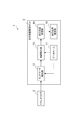
図1は、本発明の第一の実施形態に係る自己位置推定装置を示すシステム構成図である。図1に示すように、自己位置推定装置1は、ランドマークとして用いられる対象物を検出するステレオカメラ2と、自己位置推定処理を実行する自己位置推定用電子制御ユニット(以下、自己位置推定ECUという)3とを備えている。また、自己位置推定ECU3は、データベース11、ランドマーク抽出部12、地図照合部13、自己位置投票部14、および自己位置推定部15を備えている。
FIG. 1 is a system configuration diagram showing the self-position estimation apparatus according to the first embodiment of the present invention. As shown in FIG. 1, a self-position estimation apparatus 1 includes a
ステレオカメラ2は、周囲の実環境を撮像し、この実環境からランドマークを抽出するための画像データを取得するものである。ステレオカメラ2は、取得した画像データを自己位置推定ECU3におけるランドマーク抽出部12に出力する。
The
自己位置推定ECU3におけるデータベース11は、ランドマークが設定されている領域(部屋の中や屋外など)の地図、この地図上における複数のランドマークの位置、これらのランドマークのそれぞれの特徴量、およびそれぞれのランドマークを観測可能な範囲であり、ランドマークごとに決定された検出範囲である観測可能範囲を記憶している。データベース11からは、ランドマーク抽出部12に対してランドマークの特徴量が出力される。また、地図照合部13に対して、地図上における複数のランドマークの位置およびそれぞれの観測可能範囲を出力する。データベース11は、検出範囲記憶手段を構成する。
The
ランドマーク抽出部12においては、ステレオカメラ2から出力された画像およびデータベース11から出力されたランドマーク特徴量に基づいて、ステレオカメラ2から出力された画像内におけるランドマークを抽出する。ここで、ステレオカメラ2から出力された画像内におけるランドマークを抽出する際に、画像特徴SIFT(Scale-Invariant Feature Transform、以下「SIFT」という)が用いられる。SIFTでは、角度と大きさの変化に対して不変な特徴量を抽出することにより、ランドマークを抽出する。
The
データベース11には、複数のランドマークが登録されており、登録されたランドマークのランドマーク特徴量として、ランドマークをカメラで撮影した際の画像が記憶されている。SIFTによるランドマーク抽出では、ランドマークを撮影した際のカメラのカメラ姿勢から±30度程度ずれると、ランドマークの対応付けが困難になり、ランドマークの抽出が非常に困難となる。したがって、逆に考えると、SIFTによってランドマークを抽出することができた場合には、ステレオカメラ2の位置(自己位置)が抽出されたランドマークから±30度の範囲にあるといえる。したがって、SIFTによってランドマークが抽出されることにより、自己位置の自己存在可能範囲を限定されることとなる。
A plurality of landmarks are registered in the
さらに、ランドマーク抽出部12においては、ランドマークを抽出した場合、ステレオカメラ2から出力された画像に基づいて、抽出したランドマークと自己位置との距離を算出する。抽出したランドマークと自己位置との距離の算出は、たとえば三角法によって行うことができる。このように、ランドマーク抽出部12は、ランドマーク検出手段および距離検出手段を構成する。ランドマーク抽出部12は、抽出したランドマークおよび抽出したランドマークと自己位置との距離を地図照合部13に出力する。
Further, when the landmark is extracted, the
地図照合部13は、ランドマーク抽出部12から出力されたランドマークをデータベース11から出力された地図上における複数のランドマークの位置に照合し、地図上におけるランドマーク位置を検出する。また、地図照合部13では、地図上におけるランドマーク位置を検出したら、ランドマーク抽出部12から出力された距離およびデータベース11から出力された観測可能範囲に基づいて、自己が存在可能な範囲である自己存在可能範囲を推定する。ここで、地図照合部13では、ランドマーク抽出部12から出力された距離情報が短い場合には、距離情報が長い場合よりも自己存在可能範囲が狭くなるように自己存在可能範囲を推定する。このように、地図照合部13は、自己存在可能範囲推定手段を構成する。地図照合部13は、推定した自己存在可能範囲を自己位置投票部14に出力する。
The
自己位置投票部14では、地図照合部13から出力された自己存在可能範囲に自己位置候補点を設定し、各自己位置候補点に対する投票を行う。自己位置投票部14は、自己位置候補点に対して行った投票の投票結果を自己位置推定手段である自己位置推定部15に出力する。自己位置推定部15では、自己位置投票部14から出力された投票結果に基づいて、自己位置を推定する。
The self-
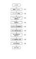
次に、本実施形態に係る自己位置推定装置における自己位置の推定手順について説明する。図2は、本実施形態に係る自己位置推定装置における自己位置推定手順を示すフローチャートである。 Next, a self-position estimation procedure in the self-position estimation apparatus according to this embodiment will be described. FIG. 2 is a flowchart showing a self-position estimation procedure in the self-position estimation apparatus according to the present embodiment.
図2に示すように、本実施形態に係る自己位置推定装置1においては、ステレオカメラ2で撮影されて出力された画像をランドマーク抽出部12に入力する(S1)。このとき、ランドマーク抽出部12には、データベース11からランドマークの特徴量が出力される。ランドマーク抽出部12では、ステレオカメラ2から出力された画像およびデータベース11から出力されたランドマークの特徴量に基づいて、画像内におけるランドマークを抽出する(S2)。ランドマークの抽出には、SIFTが用いられる。
As shown in FIG. 2, in the self-position estimation apparatus 1 according to the present embodiment, an image captured and output by the
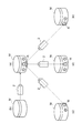
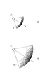
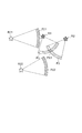
SIFTにおいては、ランドマークを登録した地点からカメラの姿勢がある程度の角度、たとえば±30度程度以上変化すると、そのランドマークとの対応付けが非常に困難となってしまう。たとえば、図3(a)に示す物体Mの表面に記された図形をランドマークRとすると、ランドマークRを正面に見た位置から90度ずれた位置から見た物体Mは、図3(b)に示すようになる。この位置から撮影した画像では、ランドマークRが撮影されず、ランドマークを抽出することができない。 In SIFT, if the camera posture changes by a certain angle, for example, about ± 30 degrees or more from the point where the landmark is registered, it becomes very difficult to associate with the landmark. For example, if the figure written on the surface of the object M shown in FIG. 3A is a landmark R, the object M viewed from a position shifted by 90 degrees from the position of the landmark R viewed in front is shown in FIG. As shown in b). In the image photographed from this position, the landmark R is not photographed, and the landmark cannot be extracted.
また、ランドマークRを正面に見た位置から時計周り方向を正として、+30度、0度、−30度程度周った位置から見た物体Mは、それぞれ図3(c)、(d)、(e)に示すようになる。図3(b)〜(e)に示すように、ランドマークRを正面から見た位置から±30程度周った位置からは、ランドマークRを抽出することができるが、これより大きく周った位置からは、ランドマークRを抽出することができなくなる。こうして、ランドマークの抽出を行う。 Further, the object M viewed from a position around +30 degrees, 0 degrees, and −30 degrees with the clockwise direction from the position viewed from the front of the landmark R as positive is shown in FIGS. 3C and 3D, respectively. (E). As shown in FIGS. 3B to 3E, the landmark R can be extracted from a position around ± 30 from the position when the landmark R is viewed from the front. From the position, the landmark R cannot be extracted. In this way, landmarks are extracted.
ランドマークの抽出が済んだら、抽出したランドマークとステレオカメラ2が設置された自己位置との距離を算出する(S3)。この距離の算出は、抽出されたすべてのランドマークに対して行い、その手法として三角法を用いる。こうして、ランドマークの抽出およびランドマークと自己位置との距離の算出が済んだら、ランドマーク抽出部12は、抽出したランドマークおよびランドマークと自己位置との距離を地図照合部13に出力する。また、地図照合部13には、データベース11から地図、この地図上におけるランドマークの位置、および観測可能範囲が出力される。
When the landmark is extracted, the distance between the extracted landmark and the self-position where the
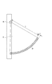
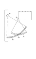
地図照合部13では、ランドマーク抽出部12から出力されたランドマークおよび地図上におけるランドマークの位置を照合し(S4)、地図上における抽出されたランドマークの位置を特定する。ランドマークの位置を特定したら、各ランドマークとの距離およびランドマークを観測可能範囲に基づいて、自己存在可能範囲を推定する(S5)。自己存在可能範囲は、次のようにして推定される。図4は、ランドマークRが抽出された領域を平面視する図である。図4において、抽出されたランドマークRの観測可能範囲Eは、データベース11に予め記憶された範囲であり、ランドマークRを登録した際にランドマークRを撮影した位置から所定の範囲、本実施形態では±30度の範囲に設定されている。このため、観測可能範囲Eとしては、中心角が60度とされた扇形が設定されている。
The
このランドマークRの観測可能範囲Eから、ランドマークRとの距離に基づいて自己存在可能範囲を絞り込むことによって自己存在可能範囲Pを推定する。自己存在可能範囲Pとしては、観測可能範囲Eにおける厚さを持った円弧を推定する。自己存在可能範囲Pを推定するにあたり、まず、円弧の半径Lを推定する。この半径Lは、自己位置とランドマークRとの距離に基づいて推定され、自己位置とランドマークRとの距離と比例した値とされる。ここでの円弧の半径Lとは、厚さを有する円弧のうち、もっとも内側の線までの距離をいう。 From the observable range E of the landmark R, the self-existing range P is estimated by narrowing down the self-existing range based on the distance from the landmark R. As the possible self existence range P, an arc having a thickness in the observable range E is estimated. In estimating the self-existing possible range P, first, the radius L of the arc is estimated. The radius L is estimated based on the distance between the self position and the landmark R, and is a value proportional to the distance between the self position and the landmark R. The radius L of the arc here refers to the distance to the innermost line among the arcs having a thickness.
このように、自己存在可能範囲Pを設定するにあたり、円弧状の観測可能範囲Eを設定し、自己位置とランドマークRとの距離と比例した値の半径Lを設定して自己存在可能範囲Pを設定する。このため、自己位置からランドマークRまでの距離が短い場合に、自己位置からランドマークRまでの距離が長い場合と比較して、自己存在可能範囲Pが狭く推定される。 In this way, in setting the self-existable range P, the arc-shaped observable range E is set, and the radius L having a value proportional to the distance between the self-position and the landmark R is set, and the self-existable range P Set. For this reason, when the distance from the self-position to the landmark R is short, the self-existing range P is estimated to be narrower than when the distance from the self-position to the landmark R is long.
円弧の半径Lを求めたら、円弧の厚さを求める。ここで、ステレオカメラ2で撮影された画像では、ランドマークと自己位置との距離が長い場合、その距離が短い場合よりも距離の計測誤差が大きくなる傾向にある。この計測誤差を考慮して、円弧の厚さTは、自己位置とランドマークRとの距離に基づいて求め、自己位置とランドマークRとの距離が短い場合に、自己位置とランドマークRとの距離が長い場合と比較して、円弧の厚さTを小さく設定する。このようにして自己存在可能範囲Pを推定することにより、自己位置を精度よく推定することができる。地図照合部13は、推定した自己存在可能範囲Pを自己位置投票部14に出力する。
When the radius L of the arc is obtained, the thickness of the arc is obtained. Here, in the image photographed by the
自己存在可能範囲Pの推定が済んだら、自己位置投票部14においては、出力された自己存在可能範囲P内に自己位置候補点を設定する(S6)。ここでの自己位置候補点は、たとえば自己存在可能範囲Pを格子状に区切って形成される各点(領域)とすることもができるし、自己存在可能範囲P内における各画素あるいは数個の画素の集合体を自己位置候補点とすることもできる。自己位置候補点を設定したら、各自己位置候補点に対して同一の投票値を付与するとともに、これらの投票値に対して、重み付けを行う(S7)。
When the self-existing possible range P is estimated, the self-
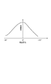
自己位置候補点の投票値に対して重み付けを行う際、図5に示すように、推定した自己存在可能範囲Pに対して中心部ほど高く、縁部に向かうにしたがって低くなる重みを付す。図5には、重みが大きい位置ほど濃くなるグラデーションを付すことにより、重み付けの割合を表現している。SIFTによってランドマークの抽出を行った際、ランドマークの抽出(マッチング)精度は、視点変化が大きくなるにしたがって低下する。このため、図6に示すように、自己位置としては、ランドマークRを登録した際にランドマークRを撮影した位置に近い位置に存在する可能性が高いことになる。このため、図5に示すように、推定した自己存在可能範囲Pに対して中心部ほど高く、縁部に向かうにしたがって低くなる重みを各自己位置候補点の投票値に付すことにより、自己位置の推定精度を向上させることができる。 When weighting the voting value of the self-position candidate point, as shown in FIG. 5, a weight that is higher toward the center and lower toward the edge of the estimated self-existing range P is given. In FIG. 5, the weighting ratio is expressed by adding a gradation in which the position where the weight is larger becomes darker. When landmarks are extracted by SIFT, landmark extraction (matching) accuracy decreases as the viewpoint change increases. For this reason, as shown in FIG. 6, the self-position is highly likely to be present at a position close to the position where the landmark R was photographed when the landmark R was registered. For this reason, as shown in FIG. 5, the weight of each self-position candidate point is assigned a weight that is higher in the central portion with respect to the estimated self-existing possible range P and lower toward the edge portion. The estimation accuracy of can be improved.
また、上述のとおり、ステレオカメラ2で撮影された画像では、ランドマークと自己位置との距離が長い場合、その距離が短い場合よりも距離の計測誤差が大きくなる傾向にある。このため、さらに、重み付けを行うにあたり、図7(a)に示すように、ランドマークR1と自己位置との距離が長い場合、図7(b)に示すように、ランドマークR2と自己位置との距離が短い場合よりも小さな重みを各自己位置候補点の投票値に付する。このように重み付けを行うことにより、さらに精度よく自己位置を検出することができる。
Further, as described above, in the image taken by the
こうして、自己位置候補点の投票値に重み付けを行ったら、自己位置候補点に対する投票を行う(S8)。自己位置候補点に対する投票では、各自己位置候補点における重み付けられた投票値をそれぞれ投票する。したがって、図4に示すように、自己存在可能範囲Pに重複が生じない場合には、自己位置候補点における投票値がそのまま反映されて自己位置推定が行われる。また、図8に示すように、複数、たとえば2つのランドマークR1,R2が抽出され、それぞれのランドマークR1、R2に対する自己存在可能範囲P1,P2が推定され、これらの自己存在可能範囲P1、P2が互いに重複する場合には、重複する重複自己存在可能範囲PXにおいて、重複する自己位置候補点が存在する。これらの重複する自己位置候補点については、複数の投票値が投票される。このように、ランドマークが複数抽出された際に、その重複部分となる重複自己存在可能範囲PXの自己位置候補点に複数の投票値が投票されることにより、自己位置候補点が存在しうる重複自己存在可能範囲PXをさらに絞り込むことができるので、その分精度よく自己位置を検出することができる。もちろん、さらに多数のランドマークが抽出された場合には、さらに多くの重複する自己位置候補点が存在するが、これらの重複する自己位置候補点についても同様に複数の投票値が投票される。 When the voting values of the self-position candidate points are thus weighted, voting is performed for the self-position candidate points (S8). In the voting for the self-position candidate points, the weighted voting values at the respective self-position candidate points are each voted. Therefore, as shown in FIG. 4, when there is no overlap in the self-existable range P, the voting value at the self-position candidate point is reflected as it is, and self-position estimation is performed. Further, as shown in FIG. 8, a plurality of, for example, two landmarks R1, R2 are extracted, and self-existing ranges P1, P2 for the respective landmarks R1, R2 are estimated, and these self-existing ranges P1, When P2 overlaps each other, there are overlapping self-position candidate points in the overlapping overlapping self-existing range PX. A plurality of vote values are voted for these overlapping self-position candidate points. As described above, when a plurality of landmarks are extracted, a plurality of voting values are voted for the self-position candidate points in the overlapping self-existing possible range PX which becomes the overlapping portion, so that self-position candidate points may exist. Since the overlapping self-existable range PX can be further narrowed down, the self-position can be detected with high accuracy accordingly. Of course, when a larger number of landmarks are extracted, there are more overlapping self-position candidate points, but a plurality of vote values are similarly voted for these overlapping self-position candidate points.
自己位置候補点に対する投票が済んだら、自己位置投票部14は、投票結果を自己位置推定部15に出力する。自己位置推定部15では、投票結果に基づいて自己位置を推定する(S9)。具体的には、各自己位置候補点に投票された投票値を加算し、もっとも大きな値となった自己位置候補点を自己位置として推定する。こうして、自己位置推定装置における自己位置推定を終了する。
When the voting for the self-position candidate point is completed, the self-
このように、本実施形態に係る自己位置推定装置1では、ステレオカメラ2による撮影が行われた位置である自己位置を推定するにあたり、自己位置からランドマークRまでの距離が短い場合に、自己位置からランドマークRまでの距離が長い場合と比較して、自己存在可能範囲Pが狭く自己存在可能範囲Pを推定している。このため、自己位置とランドマークRとの距離に応じて自己存在可能範囲Pが限定されることになるので、ランドマークRが低い位置に設定されていたり、検出されるランドマークRの数が少なく、たとえば1つのみであったりする場合でも、高い精度で自己位置を推定することができる。
As described above, in the self-position estimation apparatus 1 according to the present embodiment, when estimating the self-position that is the position where the photographing by the
また、本実施形態に係る自己位置推定装置1では、複数のランドマークR1、R2が抽出された場合に、その重複部分には、複数の投票値が投票される。このため、複数のランドマークが抽出された場合、自己位置をさらに精度よく推定することができる。さらに、本実施形態に係る自己位置推定装置1では、自己位置を推定するための投票値に重み付けを行っている。このため、自己位置をさらに狭い範囲まで精度よく推定することができる。しかも、自己位置とランドマークRとの距離が短い場合には、その距離が長い場合よりも投票値に付与する重みを大きくしている。このため、さらに精度よく自己位置を推定することができる。 Moreover, in the self-position estimation apparatus 1 according to the present embodiment, when a plurality of landmarks R1 and R2 are extracted, a plurality of voting values are voted for the overlapping portions. For this reason, when a plurality of landmarks are extracted, the self-position can be estimated with higher accuracy. Furthermore, the self-position estimation apparatus 1 according to the present embodiment weights the vote values for estimating the self-position. For this reason, the self-position can be accurately estimated to a narrower range. Moreover, when the distance between the self-position and the landmark R is short, the weight given to the vote value is set larger than when the distance is long. For this reason, the self-position can be estimated with higher accuracy.
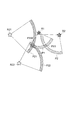
また、上記第一の実施形態においては、複数のランドマークが抽出された場合でも、複数のランドマークについては同等に扱うようにしていたが、複数のランドマークが抽出された場合に、自己位置から遠いランドマークよりも、自己位置に近いランドマークを優先的に利用する態様とすることもできる。たとえば、図9に示すように、第1ランドマークR1〜第4ランドマークRが抽出された場合、第1ランドマークR1よりも第2ランドマークR2の方が自己位置に近く、第3ランドマークR3よりも第4ランドマークR4の方が自己位置に近い場合には、第1ランドマークR1に対する自己存在可能範囲P1と第3ランドマークR3に対する自己存在可能範囲P3との重複自己存在可能範囲PX1よりも、第2ランドマークR2に対する自己存在可能範囲P2と第4ランドマークR4に対する自己存在可能範囲P4との重複自己存在可能範囲PX2を優先的に利用するようにする。 In the first embodiment, even when a plurality of landmarks are extracted, the plurality of landmarks are treated equally. However, when a plurality of landmarks are extracted, the self-position It is also possible to adopt a mode in which landmarks closer to the self position are used preferentially than landmarks far from the vehicle. For example, as shown in FIG. 9, when the first landmark R1 to the fourth landmark R are extracted, the second landmark R2 is closer to its own position than the first landmark R1, and the third landmark When the fourth landmark R4 is closer to the self position than R3, the overlapping self-existing range PX1 of the self-existing range P1 with respect to the first landmark R1 and the self-existing range P3 with respect to the third landmark R3 Instead, the overlapping self-existing range PX2 between the self-existing range P2 for the second landmark R2 and the self-existing range P4 for the fourth landmark R4 is preferentially used.
ランドマークと自己位置との関係は、上述のように、自己位置から近い位置のランドマークの方が、距離の計測誤差が小さくなる傾向にある。したがって、ランドマークが複数抽出された場合には、自己位置から遠いランドマークよりも、自己位置に近いランドマークを優先的に利用する態様とすることにより、さらに精度よく自己位置を推定することができる。 Regarding the relationship between the landmark and the self-position, as described above, the distance measurement error tends to be smaller in the landmark closer to the self-position. Therefore, when a plurality of landmarks are extracted, the self-position can be estimated more accurately by adopting a mode in which a landmark near the self-position is used preferentially over a landmark far from the self-position. it can.
次に、本発明の第二の実施形態について説明する。本実施形態に係る自己位置推定装置は、上記第一の実施形態と比較して、システム構成は上記第一の実施形態と同様であり、地図照合部13における自己存在可能範囲の推定手順が主に異なる。以下、図10を参照して本実施形態に係る自己位置推定装置に自己位置推定手順について説明する。
Next, a second embodiment of the present invention will be described. Compared with the first embodiment, the self-position estimation apparatus according to the present embodiment has the same system configuration as that of the first embodiment, and the
図10に示すように、本実施形態に係る自己位置推定装置においては、ステレオカメラ2で撮影されて出力された画像をランドマーク抽出部12に入力し(S11)、次に、ランドマーク抽出部12において、ステレオカメラ2から出力された画像およびデータベース11から出力されたランドマークの特徴量に基づいて、画像内におけるランドマークを抽出する(S12)。続いて、抽出したランドマークとステレオカメラ2が設置された自己位置との距離を算出し(S13)、その後、地図照合部13において、ランドマーク抽出部12から出力されたランドマークおよび地図上におけるランドマークの位置を照合する(S14)。ここまでは、上記第一の実施形態と同様の手順が進行する。
As shown in FIG. 10, in the self-position estimation apparatus according to the present embodiment, an image captured and output by the
さらに、各ランドマークとの距離およびランドマークを観測可能範囲に基づいて、自己存在可能範囲を推定する(S15)。ここで、本実施形態における自己存在可能範囲の推定を行う際、SIFTで抽出可能とされるランドマークを撮影した位置から±30度の範囲よりも狭い範囲に観測可能範囲を設定し、この狭い範囲に設定された観測可能範囲内から、ランドマークとの距離に基づいて、自己存在可能範囲を推定する。 Further, the self-existing possible range is estimated based on the distance to each landmark and the observable range of the landmark (S15). Here, when estimating the self-existing possible range in the present embodiment, an observable range is set in a range narrower than a range of ± 30 degrees from a position where a landmark that can be extracted by SIFT is captured. The self-existing range is estimated from the observable range set in the range based on the distance from the landmark.
SIFTによってランドマークの検出を行う際、データベース11に登録されたランドマークを抽出する一方で、データベース11に登録されたランドマークに類似する異なるランドマーク(以下「異ランドマーク」という)を誤認識して抽出してしまうことがある。このような異ランドマークを誤認識して抽出してしまうと、自己位置推定の精度が低下してしまう。
When landmarks are detected by SIFT, landmarks registered in the
たとえば、図11に示すように、2つのランドマークR1,R2と2つの異ランドマークR21,R22が抽出されたとする。この場合、2つのランドマークR1,R2に対する自己存在可能範囲が重複する重複自己存在可能範囲PX1に自己位置が存在する可能性が高いはずである。ところが、2つの異ランドマークR21,R22が抽出されていることから、2つの異ランドマークR21,R22が重複する重複異自己存在可能範囲PXWに自己位置が存在すると誤認識される可能性が高くなってしまう。 For example, assume that two landmarks R1, R2 and two different landmarks R21, R22 are extracted as shown in FIG. In this case, it is highly likely that the self-position exists in the overlapping self-existing range PX1 where the self-existing ranges for the two landmarks R1 and R2 overlap. However, since the two different landmarks R21 and R22 are extracted, there is a high possibility that the self-position exists in the overlapping different self-existence possible range PXW where the two different landmarks R21 and R22 overlap. turn into.
このような誤認識を防止するために、まずは狭い範囲で自己存在可能範囲を設定し、自己位置が推定可能でない場合には、自己存在可能範囲を拡張するようにする。正しく認識されたランドマークの自己存在可能範囲は、あるエリアに収束する傾向にあるが、誤認識された異ランドマークの自己存在可能範囲は、ばらばらに存在し、あるエリアに収束することはない傾向にある。また、ランドマークおよび異ランドマークを抽出した際には、これらがランドマークであるか異ランドマークであるかは識別できない。このため、図12に示すように、ランドマークR1,R2、および異ランドマークR21,R22に対して、まずは狭い範囲で自己存在可能範囲P1,P2,P21,P22を設定しておく。その後の投票によって一定値以上の投票が得られ、現在位置が求まるまで自己存在可能範囲を順次拡張する。このように自己存在可能範囲を推定することにより、異ランドマークが抽出された際の影響を抑制することができ、精度よく自己位置の推定を行うことができる。 In order to prevent such misrecognition, first, a self-existing range is set in a narrow range, and when the self-position cannot be estimated, the self-existing range is extended. The self-existing range of correctly recognized landmarks tends to converge to a certain area, but the misidentified self-existing range of different landmarks is scattered and never converges to a certain area. There is a tendency. Further, when landmarks and different landmarks are extracted, it is not possible to identify whether these are landmarks or different landmarks. For this reason, as shown in FIG. 12, first, self-existing possible ranges P1, P2, P21, and P22 are set in a narrow range for the landmarks R1 and R2 and the different landmarks R21 and R22. Subsequent voting results in a vote exceeding a certain value, and the self-existing range is sequentially expanded until the current position is obtained. By estimating the self-existing range in this way, it is possible to suppress the influence when different landmarks are extracted, and to perform self-position estimation with high accuracy.
こうして、自己存在可能範囲を推定したら、上記第一の実施形態と同様にして自己位置候補点を設定し(S16)、自己位置候補点に重み付けを行う(S17)。それから、自己位置候補点に投票を行う(S18)。その後、本実施形態に係る自己位置推定装置では、自己位置の推定が可能であるか否かを判定する(S19)。自己位置の推定が可能であるか否かは、自己位置候補点における投票値の最大値が所定のしきい値を超えているか否かによって判定する。 When the self-existable range is estimated in this way, self-position candidate points are set in the same manner as in the first embodiment (S16), and the self-position candidate points are weighted (S17). Then, voting is performed for the self-position candidate points (S18). Thereafter, the self-position estimation apparatus according to the present embodiment determines whether or not self-position estimation is possible (S19). Whether or not the self-position can be estimated is determined by whether or not the maximum value of the vote value at the self-position candidate point exceeds a predetermined threshold value.
その結果、自己位置候補点における投票値の最大値が所定のしきい値を超えておらず、自己位置の推定が可能でないと判定した場合には、ステップS15で求めた自己存在可能範囲を拡張し(S20)、ステップS16に戻る。このように、自己存在可能範囲を拡張することにより、複数の自己存在可能範囲が重複して重複自己存在可能範囲PXが生じる。重複自己存在可能範囲PXが生じることにより、自己位置候補点における投票値の最大値が増大し、やがて所定のしきい値を超えることになる。ここで、上述のように異ランドマークはランドマークに比べてその存在エリアが収束しない傾向にあることから、異ランドマークによる重複自己存在可能範囲は生じにくいものとなる。このため、異ランドマークによる影響を抑制することができる。 As a result, when it is determined that the maximum value of the vote value at the self-position candidate point does not exceed the predetermined threshold value and the self-position cannot be estimated, the self-existing range obtained in step S15 is expanded. (S20), the process returns to step S16. In this way, by extending the self-existing range, a plurality of self-existing ranges are overlapped to generate an overlapping self-existing range PX. As a result of the occurrence of the overlapping self-existing range PX, the maximum value of the vote value at the self-position candidate point increases and eventually exceeds a predetermined threshold value. Here, as described above, the existence area of different landmarks has a tendency not to converge as compared with the landmark, and therefore, an overlapping self-existence possible range due to different landmarks is less likely to occur. For this reason, the influence by a different landmark can be suppressed.
そして、自己位置候補点における投票値の最大値が所定のしきい値を超えて、自己位置の推定が可能であると判定した場合には、自己位置の推定を行って(S21)、自己位置推定を終了する。このように、本実施形態に係る自己位置推定装置では、異ランドマークを誤認識した場合でも、その影響を抑制することができるので、精度よく自己位置の推定を行うことができる。 Then, when it is determined that the maximum value of the voting value at the self-position candidate point exceeds a predetermined threshold and the self-position can be estimated, the self-position is estimated (S21). End the estimation. As described above, in the self-position estimation apparatus according to the present embodiment, even when a different landmark is erroneously recognized, the influence can be suppressed, so that the self-position can be estimated with high accuracy.
以上、本発明の好適な実施形態について説明したが、本発明は上記実施形態に限定されるものではない。たとえば、上記実施形態ではランドマークの抽出を行う際にSIFTを用いているが、指向性RFIDタグなどを用いた抽出を行うこともできる。この場合、ランドマーク検出手段としては、RFIDタグリーダが用いられる。他方、ランドマーク検出手段としてはレンジファインダなどを用いることもできる。 The preferred embodiment of the present invention has been described above, but the present invention is not limited to the above embodiment. For example, in the above embodiment, SIFT is used when extracting landmarks, but extraction using a directional RFID tag or the like can also be performed. In this case, an RFID tag reader is used as the landmark detection means. On the other hand, a range finder or the like can be used as the landmark detection means.
また、自己位置とランドマークとの距離を求めるために三角法を用いているが、多重解像度テンプレートなどを用いることもできる。さらに、上記実施形態においては、自己位置推定装置をロボット等の移動体に適用しているが、たとえば、乗用車等のその他の移動体に適用してもよい。 Further, trigonometry is used to obtain the distance between the self position and the landmark, but a multi-resolution template or the like can also be used. Furthermore, in the above embodiment, the self-position estimation apparatus is applied to a moving body such as a robot, but may be applied to other moving bodies such as a passenger car.
1…自己位置推定装置、2…ステレオカメラ、11…データベース、12…ランドマーク抽出部、13…地図照合部、14…自己位置投票部、15…自己位置推定部、E…観測可能範囲、3…自己位置推定ECU、L…半径、M…物体、P,P1〜P4…自己存在可能範囲、PX,PX1,PX2…重複自己存在可能範囲、PXW…重複異自己存在可能範囲、R,R1〜R4…ランドマーク、R21,R22…異ランドマーク。 DESCRIPTION OF SYMBOLS 1 ... Self-position estimation apparatus, 2 ... Stereo camera, 11 ... Database, 12 ... Landmark extraction part, 13 ... Map collation part, 14 ... Self-position voting part, 15 ... Self-position estimation part, E ... Observable range, 3 ... Self-position estimation ECU, L ... radius, M ... object, P, P1 to P4 ... self-existable range, PX, PX1, PX2 ... overlapping self-existing range, PXW ... overlapping different self-existing range, R, R1 R4 ... landmark, R21, R22 ... different landmark.
Claims (5)
自己位置から前記ランドマークまでの距離を検出する距離検出手段と、
前記ランドマークを検出可能とされる範囲として前記ランドマークごとに決定された検出範囲を記憶する検出範囲記憶手段と、
前記距離検出手段によって検出された距離と前記検出範囲記憶手段に記憶された検出範囲とに基づいて、自己が存在可能であり、複数の自己位置候補点を含む自己存在可能範囲を推定する自己存在可能範囲推定手段と、
前記自己存在可能範囲推定手段で推定した自己存在可能範囲に基づいて自己位置を推定する自己位置推定手段と、を備え、
前記自己位置推定手段は、前記ランドマーク検出手段によって複数のランドマークが検出された際、前記複数のランドマークのそれぞれに対して推定された複数の自己存在可能範囲における各自己存在候補位置に投票を行い、前記投票の結果に基づいて、自己位置を推定するものであり、
前記自己存在可能範囲推定手段は、前記自己位置から前記ランドマークまでの距離が短い場合に、前記自己位置から前記ランドマークまでの距離が長い場合と比較して、前記自己存在可能範囲を狭く推定することを特徴とする自己位置推定装置。 Landmark detection means for detecting landmarks;
Distance detecting means for detecting the distance from the self-position to the landmark;
Detection range storage means for storing a detection range determined for each landmark as a range in which the landmark can be detected;
Based on the stored detection range in the detection range storage means and detected distance by said distance detection means, Ri itself can exist der self to estimate the self-existence range including a plurality of self-position candidate point Possible existence range estimation means,
Self-position estimation means for estimating a self-position based on the self-existence possible range estimated by the self-existence possible range estimation means,
The self-position estimating unit votes each self-existing candidate position in a plurality of possible self-existing ranges estimated for each of the plurality of landmarks when the landmark detecting unit detects a plurality of landmarks. And estimating the self-position based on the result of the vote,
The self-existable range estimation means estimates the self-existable range narrower when the distance from the self-position to the landmark is short than when the distance from the self-position to the landmark is long. A self-position estimation apparatus characterized by:
前記自己存在可能範囲の中心に近い位置では、前記自己存在可能範囲の中心に遠い位置と比較して、自己位置推定に用いる重み付けを大きくする請求項2に記載の自己位置推定装置。 The self-position estimating unit weights each position in the self-existing range estimated by the self-existing range estimation unit,
3. The self-position estimation apparatus according to claim 2, wherein the weight used for self-position estimation is increased at a position close to the center of the self-existing range compared to a position far from the center of the self-existing range.
前記ランドマークに近い位置では、前記ランドマークから遠い位置と比較して、自己位置推定に用いる重み付けを大きくする請求項2または請求項3に記載の自己位置推定装置。 The self-position estimating unit weights each position in the self-existing range estimated by the self-existing range estimation unit,
4. The self-position estimation apparatus according to claim 2, wherein a weight used for self-position estimation is increased at a position close to the landmark compared to a position far from the landmark.
前記自己位置推定手段が自己位置を推定できないと判定した場合に、前記自己存在可能範囲推定手段は、前記自己存在可能範囲を拡張する請求項2〜請求項4のうちのいずれか1項に記載の自己位置推定装置。 The self-position estimating means determines whether or not the self-position can be estimated based on the self-existable range estimated by the self-existable range estimating means;
5. The self-existing range estimating unit expands the self-existing range when the self-position estimating unit determines that the self-position cannot be estimated. 5. Self-position estimation device.
Priority Applications (1)
| Application Number | Priority Date | Filing Date | Title |
|---|---|---|---|
| JP2006204934A JP4882575B2 (en) | 2006-07-27 | 2006-07-27 | Self-position estimation device |
Applications Claiming Priority (1)
| Application Number | Priority Date | Filing Date | Title |
|---|---|---|---|
| JP2006204934A JP4882575B2 (en) | 2006-07-27 | 2006-07-27 | Self-position estimation device |
Publications (2)
| Publication Number | Publication Date |
|---|---|
| JP2008032478A JP2008032478A (en) | 2008-02-14 |
| JP4882575B2 true JP4882575B2 (en) | 2012-02-22 |
Family
ID=39122071
Family Applications (1)
| Application Number | Title | Priority Date | Filing Date |
|---|---|---|---|
| JP2006204934A Expired - Fee Related JP4882575B2 (en) | 2006-07-27 | 2006-07-27 | Self-position estimation device |
Country Status (1)
| Country | Link |
|---|---|
| JP (1) | JP4882575B2 (en) |
Families Citing this family (4)
| Publication number | Priority date | Publication date | Assignee | Title |
|---|---|---|---|---|
| JP5557189B2 (en) * | 2010-03-31 | 2014-07-23 | トヨタ自動車株式会社 | Position estimation apparatus, position estimation method and program |
| US8798840B2 (en) * | 2011-09-30 | 2014-08-05 | Irobot Corporation | Adaptive mapping with spatial summaries of sensor data |
| CN118816924A (en) * | 2015-02-10 | 2024-10-22 | 御眼视觉技术有限公司 | Sparse maps for autonomous vehicle navigation |
| JP6594008B2 (en) * | 2015-03-23 | 2019-10-23 | 株式会社メガチップス | Mobile control device, landmark, and program |
Family Cites Families (3)
| Publication number | Priority date | Publication date | Assignee | Title |
|---|---|---|---|---|
| JP3494075B2 (en) * | 1999-05-25 | 2004-02-03 | 三菱電機株式会社 | Self-locating device for moving objects |
| JP3968501B2 (en) * | 2001-11-30 | 2007-08-29 | ソニー株式会社 | Robot self-position identification system and self-position identification method |
| JP4319618B2 (en) * | 2004-12-28 | 2009-08-26 | 株式会社東芝 | Mobile robot device |
-
2006
- 2006-07-27 JP JP2006204934A patent/JP4882575B2/en not_active Expired - Fee Related
Also Published As
| Publication number | Publication date |
|---|---|
| JP2008032478A (en) | 2008-02-14 |
Similar Documents
| Publication | Publication Date | Title |
|---|---|---|
| JP4985166B2 (en) | Self-position estimation device | |
| US9984280B2 (en) | Object recognition system using left and right images and method | |
| CN101271333B (en) | Localization method for a moving robot | |
| JP4794625B2 (en) | Image processing apparatus and image processing method | |
| US20220156973A1 (en) | Information processing apparatus, information processing method, and program | |
| CN103824080B (en) | Robot SLAM object state detection method in dynamic sparse environment | |
| CN113508420B (en) | Object tracking device, object tracking method and storage medium | |
| WO2013032192A2 (en) | Method for recognizing position of mobile robot by using features of arbitrary shapes on ceiling | |
| Klippenstein et al. | Quantitative evaluation of feature extractors for visual slam | |
| US10147015B2 (en) | Image processing device, image processing method, and computer-readable recording medium | |
| JP2010033447A (en) | Image processor and image processing method | |
| Paral et al. | Vision sensor-based shoe detection for human tracking in a human–robot coexisting environment: A photometric invariant approach using DBSCAN algorithm | |
| JP5936561B2 (en) | Object classification based on appearance and context in images | |
| US20180158203A1 (en) | Object detection device and object detection method | |
| JP2014134856A (en) | Subject identification device, subject identification method, and subject identification program | |
| CN105989586A (en) | SLAM method based on semantic bundle adjustment method | |
| US20130259324A1 (en) | Method for face recognition | |
| Wolf et al. | Using an image retrieval system for vision-based mobile robot localization | |
| JP4882575B2 (en) | Self-position estimation device | |
| CN113837270B (en) | Target identification method, device, equipment and storage medium | |
| Lee et al. | Multi-robot SLAM using ceiling vision | |
| JP2013254242A (en) | Image recognition device, image recognition method, and image recognition program | |
| Huang et al. | Improving keypoint matching using a landmark-based image representation | |
| WO2017179728A1 (en) | Image recognition device, image recognition method, and image recognition program | |
| KR20240080579A (en) | Apparatus and method for estimating hand posture for inteeraction in augmented reality environment |
Legal Events
| Date | Code | Title | Description |
|---|---|---|---|
| A621 | Written request for application examination |
Free format text: JAPANESE INTERMEDIATE CODE: A621 Effective date: 20090722 |
|
| A131 | Notification of reasons for refusal |
Free format text: JAPANESE INTERMEDIATE CODE: A131 Effective date: 20110301 |
|
| A977 | Report on retrieval |
Free format text: JAPANESE INTERMEDIATE CODE: A971007 Effective date: 20110303 |
|
| A521 | Request for written amendment filed |
Free format text: JAPANESE INTERMEDIATE CODE: A523 Effective date: 20110502 |
|
| TRDD | Decision of grant or rejection written | ||
| A01 | Written decision to grant a patent or to grant a registration (utility model) |
Free format text: JAPANESE INTERMEDIATE CODE: A01 Effective date: 20111108 |
|
| A01 | Written decision to grant a patent or to grant a registration (utility model) |
Free format text: JAPANESE INTERMEDIATE CODE: A01 |
|
| A61 | First payment of annual fees (during grant procedure) |
Free format text: JAPANESE INTERMEDIATE CODE: A61 Effective date: 20111121 |
|
| FPAY | Renewal fee payment (event date is renewal date of database) |
Free format text: PAYMENT UNTIL: 20141216 Year of fee payment: 3 |
|
| R151 | Written notification of patent or utility model registration |
Ref document number: 4882575 Country of ref document: JP Free format text: JAPANESE INTERMEDIATE CODE: R151 |
|
| FPAY | Renewal fee payment (event date is renewal date of database) |
Free format text: PAYMENT UNTIL: 20141216 Year of fee payment: 3 |
|
| LAPS | Cancellation because of no payment of annual fees |