EP3088983B1 - Moving object controller and program - Google Patents
Moving object controller and program Download PDFInfo
- Publication number
- EP3088983B1 EP3088983B1 EP16156694.8A EP16156694A EP3088983B1 EP 3088983 B1 EP3088983 B1 EP 3088983B1 EP 16156694 A EP16156694 A EP 16156694A EP 3088983 B1 EP3088983 B1 EP 3088983B1
- Authority
- EP
- European Patent Office
- Prior art keywords
- landmark
- time
- moving object
- information
- robot
- Prior art date
- Legal status (The legal status is an assumption and is not a legal conclusion. Google has not performed a legal analysis and makes no representation as to the accuracy of the status listed.)
- Active
Links
- 230000007613 environmental effect Effects 0.000 claims description 67
- 238000001514 detection method Methods 0.000 claims description 57
- 238000000034 method Methods 0.000 claims description 22
- 238000012545 processing Methods 0.000 claims description 21
- 238000003384 imaging method Methods 0.000 description 24
- 238000010586 diagram Methods 0.000 description 18
- 239000007787 solid Substances 0.000 description 13
- 101100299505 Schizosaccharomyces pombe (strain 972 / ATCC 24843) ptn1 gene Proteins 0.000 description 8
- 238000010191 image analysis Methods 0.000 description 5
- 238000005259 measurement Methods 0.000 description 5
- 239000002245 particle Substances 0.000 description 5
- 230000010354 integration Effects 0.000 description 4
- 230000004807 localization Effects 0.000 description 4
- 102100023190 Armadillo repeat-containing protein 1 Human genes 0.000 description 3
- 101000684952 Homo sapiens Armadillo repeat-containing protein 1 Proteins 0.000 description 3
- 238000013507 mapping Methods 0.000 description 3
- 239000004065 semiconductor Substances 0.000 description 3
- 238000004364 calculation method Methods 0.000 description 2
- 238000004891 communication Methods 0.000 description 2
- 238000004590 computer program Methods 0.000 description 2
- 238000005516 engineering process Methods 0.000 description 2
- 238000001914 filtration Methods 0.000 description 2
- 230000000007 visual effect Effects 0.000 description 2
- 238000004458 analytical method Methods 0.000 description 1
- 238000011982 device technology Methods 0.000 description 1
- 239000000284 extract Substances 0.000 description 1
- 238000012986 modification Methods 0.000 description 1
- 230000004048 modification Effects 0.000 description 1
- 230000001360 synchronised effect Effects 0.000 description 1
Images


Classifications
-
- G—PHYSICS
- G05—CONTROLLING; REGULATING
- G05D—SYSTEMS FOR CONTROLLING OR REGULATING NON-ELECTRIC VARIABLES
- G05D1/00—Control of position, course or altitude of land, water, air, or space vehicles, e.g. automatic pilot
- G05D1/02—Control of position or course in two dimensions
- G05D1/021—Control of position or course in two dimensions specially adapted to land vehicles
- G05D1/0231—Control of position or course in two dimensions specially adapted to land vehicles using optical position detecting means
- G05D1/0234—Control of position or course in two dimensions specially adapted to land vehicles using optical position detecting means using optical markers or beacons
- G05D1/0236—Control of position or course in two dimensions specially adapted to land vehicles using optical position detecting means using optical markers or beacons in combination with a laser
-
- G—PHYSICS
- G05—CONTROLLING; REGULATING
- G05D—SYSTEMS FOR CONTROLLING OR REGULATING NON-ELECTRIC VARIABLES
- G05D1/00—Control of position, course or altitude of land, water, air, or space vehicles, e.g. automatic pilot
- G05D1/0088—Control of position, course or altitude of land, water, air, or space vehicles, e.g. automatic pilot characterized by the autonomous decision making process, e.g. artificial intelligence, predefined behaviours
-
- G—PHYSICS
- G05—CONTROLLING; REGULATING
- G05D—SYSTEMS FOR CONTROLLING OR REGULATING NON-ELECTRIC VARIABLES
- G05D1/00—Control of position, course or altitude of land, water, air, or space vehicles, e.g. automatic pilot
- G05D1/02—Control of position or course in two dimensions
- G05D1/021—Control of position or course in two dimensions specially adapted to land vehicles
- G05D1/0231—Control of position or course in two dimensions specially adapted to land vehicles using optical position detecting means
- G05D1/0246—Control of position or course in two dimensions specially adapted to land vehicles using optical position detecting means using a video camera in combination with image processing means
- G05D1/0248—Control of position or course in two dimensions specially adapted to land vehicles using optical position detecting means using a video camera in combination with image processing means in combination with a laser
-
- G—PHYSICS
- G05—CONTROLLING; REGULATING
- G05D—SYSTEMS FOR CONTROLLING OR REGULATING NON-ELECTRIC VARIABLES
- G05D1/00—Control of position, course or altitude of land, water, air, or space vehicles, e.g. automatic pilot
- G05D1/02—Control of position or course in two dimensions
- G05D1/021—Control of position or course in two dimensions specially adapted to land vehicles
- G05D1/0231—Control of position or course in two dimensions specially adapted to land vehicles using optical position detecting means
- G05D1/0246—Control of position or course in two dimensions specially adapted to land vehicles using optical position detecting means using a video camera in combination with image processing means
- G05D1/0251—Control of position or course in two dimensions specially adapted to land vehicles using optical position detecting means using a video camera in combination with image processing means extracting 3D information from a plurality of images taken from different locations, e.g. stereo vision
-
- G—PHYSICS
- G05—CONTROLLING; REGULATING
- G05D—SYSTEMS FOR CONTROLLING OR REGULATING NON-ELECTRIC VARIABLES
- G05D1/00—Control of position, course or altitude of land, water, air, or space vehicles, e.g. automatic pilot
- G05D1/02—Control of position or course in two dimensions
- G05D1/021—Control of position or course in two dimensions specially adapted to land vehicles
- G05D1/0268—Control of position or course in two dimensions specially adapted to land vehicles using internal positioning means
- G05D1/0274—Control of position or course in two dimensions specially adapted to land vehicles using internal positioning means using mapping information stored in a memory device
-
- G—PHYSICS
- G06—COMPUTING; CALCULATING OR COUNTING
- G06F—ELECTRIC DIGITAL DATA PROCESSING
- G06F18/00—Pattern recognition
- G06F18/20—Analysing
- G06F18/22—Matching criteria, e.g. proximity measures
-
- G—PHYSICS
- G06—COMPUTING; CALCULATING OR COUNTING
- G06T—IMAGE DATA PROCESSING OR GENERATION, IN GENERAL
- G06T7/00—Image analysis
- G06T7/20—Analysis of motion
-
- G—PHYSICS
- G06—COMPUTING; CALCULATING OR COUNTING
- G06T—IMAGE DATA PROCESSING OR GENERATION, IN GENERAL
- G06T7/00—Image analysis
- G06T7/50—Depth or shape recovery
-
- G—PHYSICS
- G06—COMPUTING; CALCULATING OR COUNTING
- G06T—IMAGE DATA PROCESSING OR GENERATION, IN GENERAL
- G06T7/00—Image analysis
- G06T7/60—Analysis of geometric attributes
-
- G—PHYSICS
- G06—COMPUTING; CALCULATING OR COUNTING
- G06T—IMAGE DATA PROCESSING OR GENERATION, IN GENERAL
- G06T7/00—Image analysis
- G06T7/70—Determining position or orientation of objects or cameras
- G06T7/73—Determining position or orientation of objects or cameras using feature-based methods
-
- G—PHYSICS
- G06—COMPUTING; CALCULATING OR COUNTING
- G06V—IMAGE OR VIDEO RECOGNITION OR UNDERSTANDING
- G06V20/00—Scenes; Scene-specific elements
- G06V20/10—Terrestrial scenes
-
- Y—GENERAL TAGGING OF NEW TECHNOLOGICAL DEVELOPMENTS; GENERAL TAGGING OF CROSS-SECTIONAL TECHNOLOGIES SPANNING OVER SEVERAL SECTIONS OF THE IPC; TECHNICAL SUBJECTS COVERED BY FORMER USPC CROSS-REFERENCE ART COLLECTIONS [XRACs] AND DIGESTS
- Y10—TECHNICAL SUBJECTS COVERED BY FORMER USPC
- Y10S—TECHNICAL SUBJECTS COVERED BY FORMER USPC CROSS-REFERENCE ART COLLECTIONS [XRACs] AND DIGESTS
- Y10S901/00—Robots
- Y10S901/01—Mobile robot
-
- Y—GENERAL TAGGING OF NEW TECHNOLOGICAL DEVELOPMENTS; GENERAL TAGGING OF CROSS-SECTIONAL TECHNOLOGIES SPANNING OVER SEVERAL SECTIONS OF THE IPC; TECHNICAL SUBJECTS COVERED BY FORMER USPC CROSS-REFERENCE ART COLLECTIONS [XRACs] AND DIGESTS
- Y10—TECHNICAL SUBJECTS COVERED BY FORMER USPC
- Y10S—TECHNICAL SUBJECTS COVERED BY FORMER USPC CROSS-REFERENCE ART COLLECTIONS [XRACs] AND DIGESTS
- Y10S901/00—Robots
- Y10S901/46—Sensing device
- Y10S901/47—Optical
Definitions
- the present invention relates to a technique for controlling a moving object using simultaneous localization and mapping (SLAM).
- SLAM simultaneous localization and mapping
- SLAM simultaneous localization and mapping
- a sensor used to obtain observation data may typically be an RGB camera incorporating a visible light image sensor, or a range finder that obtains distance information using infrared light or laser light. Two or more different sensors may be used in combination to obtain observation data.
- a robot (moving object) that moves autonomously with SLAM typically generates a topological environmental map, instead of generating a geometric environmental map.
- the environmental map is obtained using, for example, information about landmarks.
- the environmental map contains a plurality of sets of landmark information.
- Each landmark has parameters including variance-covariance matrices expressing (1) information about the position of the landmark and (2) the uncertainty of positional information for the landmark.
- the robot When the robot that moves autonomously with SLAM incorporates an RGB camera as its sensor, the robot uses, as landmarks, points or lines with features or objects with distinguishable markers.
- the robot detects (identifies) an image region corresponding to a landmark in an image captured by the RGB camera to obtain information about the landmark.
- the actual position of the robot relative to the actual position of the landmark is determined using the image obtained by the RGB camera, and observation data at the current time is obtained based on the identification result.
- the actual position of the robot and the actual position of the landmark may not be easily estimated with high accuracy.
- the RGB camera or the range finder has high directivity and thus has a limited observable range.
- a small number of landmarks can be detected at a time based on data obtained by the RGB camera or the range finder. For example, (1) the distance from the robot to a detected landmark and (2) the angle formed by a predetermined reference axis and a straight line connecting the robot and the detected landmark as viewed from above an environment in which the robot moves are obtained as information about a landmark. In this case, the position of the robot may not be estimated with high accuracy based on the obtained landmark information.
- Document US 2005/182518 A1 describes a method in a visual simultaneous localization and mapping (VSLAM) system of updating a map in a robust manner, the method comprising: using visual features to recognize landmarks in an environment; maintaining the map of the visually-recognized landmarks, where the map comprises landmark poses associated with landmarks; receiving an indication that a new landmark has been observed; retrieving dead reckoning measurements observed from a prior pose; receiving an indication of whether the dead reckoning measurements are trustworthy; at least partially in response to determining that the dead reckoning measurements are trustworthy, then performing: using the dead reckoning measurements and the prior pose to compute a landmark pose for the new landmark L; associating the computed landmark pose with the new landmark; and storing the landmark pose and the association to the new landmark L to update the map; and, at least partially in response to determining that the dead reckoning measurements are not trustworthy, then not updating the, map with the new landmark.
- VSLAM visual simultaneous localization and mapping
- Document US 2010/215216 A1 describes a localization system and method to recognize the location of an autonomous mobile platform.
- a beacon three-dimensional structure
- the mobile platform which knows image pattern information of the beacon photographs the image of the beacon and finds and analyzes a pattern to be recognized from the photographed image.
- a relative distance and a relative angle of the mobile platform are computed using the analysis of the pattern such that the location of the mobile platform is accurately recognized.
- Document US 2004/239756 A1 describes techniques for computing error-bounded position and orientation (pose) of a panoramic camera in real-world environments.
- environments comprise large interior spaces (e.g., buildings), wherein a space comprises multiple rooms.
- a technique for capturing images associated with an environment comprises the following steps/operations. First, respective placements of fiducials in the environment are determined so as to satisfy at least one constraint. Images are captured, with an image capture device (e.g., camera), associated with the environment with the fiducials placed therein. A pose estimation of the image capture device is then determined based on projections of the fiducials in the captured images. The pose estimation is optimized so as to obtain an optimal pose per image.
- an image capture device e.g., camera
- the fiducial placements are optimized so as to obtain optimal fiducial placements.
- at least one constraint comprises a constraint associated with the number of visible fiducials, a constraint associated with a distance from a viewpoint to a fiducial, and/or a constraint associated with an angle subtended by pairs of fiducials.
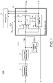
- Fig. 1 is a schematic block diagram of a moving object controller 1000 according to a first embodiment.
- the moving object controller 1000 is mounted on a moving object, such as an autonomous robot Rbtl (not shown).
- the moving object controller 1000 includes an observation obtaining unit 1, a landmark detection unit 2, a candidate area obtaining unit 3, a state estimation unit 4, and a storage unit 5.
- observation data D1 obtained by the observation obtaining unit 1 includes an image (image data) captured by an imaging device incorporating a distance sensor (not shown), which is mounted on the moving object (robot Rbtl), and a distance image (distance data) obtained by the imaging device incorporating the distance sensor.
- the observation obtaining unit 1 receives data obtained by the imaging device incorporating the distance sensor (not shown), which is mounted on the moving object (robot Rbtl), as input data Din.
- the observation obtaining unit 1 obtains the observation data D1, which includes an image (image data) D1_img and a distance image (distance data) D1_d, based on the input data Din.
- the observation obtaining unit 1 outputs the obtained observation data D1 to the landmark detection unit 2 and a state update unit 41 included in the state estimation unit 4.
- the landmark detection unit 2 receives the observation data D1, which is output from the observation obtaining unit 1.
- the landmark detection unit 2 obtains information about the distance and the direction (angle) from the robot Rbtl to a landmark based on the observation data D1 (the image data D1_img and the distance image D1_d).
- the landmark detection unit 2 outputs a signal including the obtained information to the candidate area obtaining unit 3, and the state update unit 41 and an environmental map update unit 42 included in the state estimation unit 4 as a landmark detection signal LM t .
- the candidate area obtaining unit 3 receives the landmark detection signal LM t output from the landmark detection unit 2. Based on the landmark detection signal LM t , the candidate area obtaining unit 3 obtains robot position candidate information Cdt t , which is used to estimate the candidate position for the position of the robot Rbtl at the current time. The candidate area obtaining unit 3 outputs the obtained robot position candidate information Cdt t to the state update unit 41 included in the state estimation unit 4.
- the state estimation unit 4 includes the state update unit 41 and the environmental map update unit 42.
- the state update unit 41 estimates the internal state of the robot Rbtl based on the observation data D1, the landmark detection signal LM t , the robot position candidate information Cdt t , the control input data U t , and the internal state data X t-1 of the robot Rbtl at time t-1 to obtain the estimation result as the internal state data X t of the moving object at the current time t (update the internal state data).
- the state update unit 41 then outputs the obtained internal state data X t of the moving object at the current time t out of the state estimation unit 4, and also to the storage unit 5.
- the internal state data X t externally output from the state estimation unit 4 is used by, for example, a function unit (central control unit) that centrally controls the moving object (automatically moving robot Rbtl) (not shown) as data to control the moving object (automatically moving robot Rbtl).
- a function unit central control unit
- the state update unit 41 also outputs the internal state data X t corresponding to the position of the robot Rbtl at the current time t to the environmental map update unit 42.
- the state update unit 41 also outputs the control input data U t for the robot Rbtl at the current time t to the storage unit 5.
- the environmental map update unit 42 receives a landmark detection signal LM t ,which is output from the landmark detection unit 2, environmental map data m t-1 at time t-1, which is read from the storage unit 5, and internal state data X t of the robot Rbtl at the current time t, which is output from the state update unit 41.
- the environmental map update unit 42 obtains information about a detected landmark based on the landmark detection signal LM t , and updates the environmental map data based on the obtained landmark information, the environmental map data m t-1 at time t-1, and the internal state data X t of the robot Rbtl at the current time t to obtain environmental map data m t at the current time t.
- the environmental map update unit 42 then outputs the updated environmental map data m t out of the state estimation unit 4, and also to the storage unit 5.
- the environmental map data m t externally output from the state estimation unit 4 is used by, for example, a function unit (central control unit) that centrally controls the moving object (automatically moving robot Rbtl) (not shown) as data to control the moving object (automatically moving robot Rbtl).
- the storage unit 5 receives and stores internal state data X t of the moving object at the current time t and control input data U t , which are output from the state update unit 41 included in the state estimation unit 4, and environmental map data m t .
- the data stored in the storage unit 5 is read by the state estimation unit 4 at predetermined timing.
- the storage unit 5 can store a plurality of sets of internal state data and environmental map data obtained at a plurality of times.
- the data at the current time t refers to data obtained using the target observation data D1 by the moving object controller 1000 (internal state data X t of the moving object and environmental map data m t ).
- the data at time t-1 preceding the current time t by one time refers to data obtained by the moving object controller 1000 at the time preceding the current time t by one time (internal state data X t-1 of the moving object and environmental map data m t-1 ).
- the data at time t-k preceding the current time t by k times refers to data obtained by the moving object controller 1000 at the time preceding the current time t by k times (internal state data X t-k of the moving object and environmental map data m t-k ).
- the above data may be obtained at synchronous timing or at asynchronous timing.
- the robot Rbtl is a moving object that moves autonomously.
- the input data Din is an image (captured image) captured by an imaging device incorporating a visible image sensor and a distance sensor (not shown), which is mounted on the robot Rbtl, and a distance image (distance data).
- the environmental map is generated based on information about landmarks.
- landmark sets each including two landmarks are arranged in an environment in which the robot Rbtl moves.
- Each set of landmarks is provided with information such as a color code or a specific pattern to differentiate from other sets of landmarks. This information is used to identify a set (landmark set) including a detected landmark.
- Fig. 2 is a diagram showing the positional relationship between candidate points C1 t and C2 t for the position of the robot Rbtl at time t, and a set of landmarks LM1A and LM1B (viewed from above).
- the space is defined by x-axis and y-axis, and the origin indicated by 0.
- the processing performed by the moving object controller will be described based on the positional relationship between the robot Rbtl and the landmarks LM1A and LM1B on a two-dimensional plane (x-y plane) as shown in Fig. 2 .
- the moving object controller may perform the processing based on the positional relationship between the robot Rbtl and the landmarks LM1A and LM1B in a three-dimensional space.
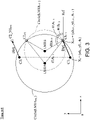
- Fig. 3 is a diagram showing the positional relationship between candidate points C1 t+1 and C2 t+1 for the position of the robot Rbtl at time t+1, and a set of landmarks LM1A and LM1B (viewed from above).
- the space is also defined by x-axis and y-axis, and the origin indicated by 0 as in Fig. 2 .
- the robot Rbtl at time t at the position indicated by the point C1 t in Fig. 2 receives control data for moving the robot in the direction of arrow Dirl shown in Fig. 3 .
- the robot Rbtl moves to the position indicated by the point C1 t+1 in Fig. 3 .
- the moving object controller 1000 uses (1) data indicating the internal state of the robot Rbtl and (2) data representing an environmental map described below.
- the moving object controller 1000 sets, as data indicating the internal state of the robot Rbtl, the internal state data X t indicating the position and the angle of the robot Rbtl at time t.
- the moving object controller 1000 uses particle filtering (Monte Carlo approximation) to estimate the internal state of the robot Rbtl.
- the posterior probability distribution of a state vector X t-1 at time t-1 is used as the prior probability distribution of the state vector X t at the current time t, and the predictive probability distribution of the state vector X t at the current time t is obtained through prediction using the prior probability distribution of the state vector X t at the current time t.
- a likelihood is then calculated based on the obtained predictive probability distribution and actual observation data (observation data at the current time t). At the ratio proportional to the calculated likelihood, particles are sampled without changing the total number of the particles.
- the moving object controller 1000 sets the data X t indicating the internal state of the robot Rbtl.
- the moving object controller 1000 sets environmental map data m t at time t as data representing an environmental map.
- the environmental map data m t includes information about landmarks.
- information about the detected landmark is added to the environmental map data m t .
- LMkAP t is internal state data corresponding to the position of one landmark included in the k-th landmark set at time t
- LMkBP t is the internal state data corresponding to the position of the other landmark included in the k-th landmark set at time t.
- One landmark set includes two landmarks.
- the moving object controller 1000 determines the set of internal state data for 2 ⁇ k landmarks included in k landmark sets as the environmental map data m t at time t.
- the environmental map data m t includes information about the two landmarks LM1A and LM1B included in one landmark set.
- Information LM1AP t about the landmark LM1A and information LM1BP t about the landmark LM1B are set in the manner described below.
- LM1AP t d 1 A t , ⁇ 1 A t
- d1A t is a distance from the robot Rbtl to the landmark LM1A
- ⁇ 1A t is an angle formed by x-axis and a straight line connecting the robot Rbtl and the landmark LM1A as viewed from above.
- LM1BP t d1B t , ⁇ 1B t
- d1B t a distance from the robot Rbtl to the landmark LM1B
- ⁇ 1B t is an angle formed by x-axis and a straight line connecting the robot Rbtl and the landmark LM1B as viewed from above.
- the robot Rbtl incorporating the moving object controller 1000 in the example described below obtains the internal state data of the robot Rbtl and environmental map data based on the two landmarks LMA1 and LMB1 included in one landmark set as shown in Figs. 2 and 3 .
- the robot Rbtl and the landmarks LM1A and LM1B are positioned as shown in Fig. 2 .
- the imaging device incorporating the distance sensor which is mounted on the moving object controller 1000, captures an captured image (image data) of an area ARcp shown in Fig. 2 and obtains a distance image (distance data).
- the observation obtaining unit 1 obtains the observation data D1, which includes the image (image data) D1_img of the area Arcp and the distance image (distance data) D1_d, from the input data Din received from the imaging device incorporating the distance sensor mounted on the moving object controller 1000.
- the observation obtaining unit 1 outputs the obtained observation data D1 to the landmark detection unit 2 and the state update unit 41 included in the state estimation unit 4.
- the landmark detection unit 2 obtains information about the distance and the direction (angle) from the robot Rbtl to the landmarks LM1A and LM1B from the observation data D1 (the image data D1_img and the distance image D1_d). More specifically, the landmark detection unit 2 obtains the data LM1AP t and the data LM1BP t described below.
- LM1AP t d1A t , ⁇ 1A t
- d1A t is a distance from the robot Rbtl to the landmark LM1A
- ⁇ 1A t is an angle formed by x-axis and a straight line connecting the robot Rbtl and the landmark LM1A as viewed from above.
- LM1BP t d1B t , ⁇ 1B t
- d1B t a distance from the robot Rbtl to the landmark LM1B
- ⁇ 1B t is an angle formed by x-axis and a straight line connecting the robot Rbtl and the landmark LM1B as viewed from above.
- a signal including the data LM1AP t and the data LM1BP t obtained for the landmarks LM1A and LM1B are output as the landmark detection signal LM t from the landmark detection unit 2 to the candidate area obtaining unit 3, and the state update unit 41 and the environmental map update unit 42 included in the state estimation unit 4.
- the candidate area obtaining unit 3 obtains information for estimating a candidate position of the robot Rbtl at the current time t.
- the candidate area obtaining unit 3 determines two intersection points C1 t and C2 t of (1) a circle centered on the point LM1A with its radius being a distance d1A t from the robot Rbtl to the landmark LM1A, and (2) a circle centered on the point LM1B with its radius being a distance d1B t from the robot Rbtl to the landmark LM1B as shown in Fig. 2 .
- the candidate area obtaining unit 3 then outputs information about the two intersection points C1 t and C2 t (information for identifying the intersection points C1 t and C2 t ) to the state update unit 41 included in the state estimation unit 4 as robot position candidate information Cdt t .
- the candidate area obtaining unit 3 may perform processing considering errors and the estimation accuracy of the landmark positions (the accuracy of the internal state data corresponding to the landmarks) and output information about an area with a predetermined size including the two intersection points C1 t and C2 t to the state update unit 41 included in the state estimation unit 4 as the robot position candidate information Cdt t .
- the state update unit 41 included in the state estimation unit 4 estimates the internal state of the robot Rbtl based on the observation data D1, the landmark detection signal LM t , the robot position candidate information Cdt t , the control input data U t , and the internal state data X t-1 of the robot Rbtl at time t-1 to obtain the estimation result as the internal state data X t of the robot Rbtl at the current time t (update the internal state data).
- the state update unit 41 estimates one of the points C1 t and C2 t , which are two candidates for the position of the robot Rbtl, as the position of the robot Rbtl at time t based on the robot position candidate information Cdt t .
- the state update unit 41 estimates the point C1 t as the position of the robot Rbtl at time t.
- the internal state data X t of the robot Rbtl at time t obtained by the state update unit 41 is output from the state update unit 41 to the storage unit 5, and is stored into the storage unit 5.
- the environmental map update unit 42 obtains information about a detected landmark based on the landmark detection signal LM t , which is output from the landmark detection unit 2.
- the environmental map update unit 42 updates the environmental map data based on the obtained landmark information, the environmental map data m t-1 at time t-1, and the internal state data X t of the robot Rbtl at the current time t to obtain the environmental map data m t at the current time t.
- the environmental map update unit 42 updates the environmental map data m t using the data obtained as described above.
- the robot Rbtl also receives a control input U t .
- the control input U t is control input data for moving the robot Rbtl in the direction of arrow Dir1 shown in Fig. 3 .
- the robot Rbtl When controlled using the control input data U t at time t, the robot Rbtl is predicted to have moved to the position indicated by the point C1 t+1 in Fig. 3 or to the position indicated by the point C2_NG t+1 in Fig. 3 at time t+1.
- the observation obtaining unit 1 obtains the observation data D1, which is the image (image data) D1_img of the area Arcp and the distance image (distance data) D1_d, from the input data Din received from the imaging device incorporating the distance sensor mounted on the moving object controller 1000.
- the observation obtaining unit 1 then outputs the obtained observation data D1 to the landmark detection unit 2 and the state update unit 41 included in the state estimation unit 4.
- the landmark detection unit 2 obtains information about the distance and the direction (angle) from the robot Rbtl to the landmarks LM1A and LM1B based on the observation data D1 (the image data D1_img and the distance image D1_d). More specifically, the landmark detection unit 2 obtains the data LM1AP t and the data LM1BP t described below.
- LM1AP t + 1 d 1 A t + 1 , ⁇ 1 A t + 1
- d1A t+1 a distance from the robot Rbtl to the landmark LM1A
- ⁇ 1A t+1 an angle formed by x-axis and a straight line connecting the robot Rbtl and the landmark LM1A as viewed from above.
- LM1BP t + 1 d 1 B t + 1 , ⁇ 1B t + 1 where dlB t+i is a distance from the robot Rbtl to the landmark LM1B, and ⁇ 1B t+1 is an angle formed by x-axis and a straight line connecting the robot Rbtl and the landmark LM1B as viewed from above.
- a signal including the data LM1AP t+1 and the LM1BP t+1 obtained for the landmarks LM1A and LM1B is output as the landmark detection signal LM t+1 from the landmark detection unit 2 to the candidate area obtaining unit 3, and the state update unit 41 and the environmental map update unit 42 included in the state estimation unit 4.
- the candidate area obtaining unit 3 obtains information for estimating the candidate position for the position of the robot Rbtl at the current time t+1.
- the candidate area obtaining unit 3 determines the two intersection points C1 t+1 and C2 t+1 of (1) a circle centered on the point LM1A with its radius being a distance d1A t+1 from the robot Rbtl to the landmark LM1A and (2) a circle centered on the point LM1B with its radius being a distance d1B t+1 from the robot Rbtl to the landmark LM1B as shown in Fig. 3 .
- the candidate area obtaining unit 3 outputs information about the two intersection points C1 t+1 and C2 t+1 (information for identifying the intersection points C1 t+1 and C2 t+1 ) to the state update unit 41 included in the state estimation unit 4 as the robot position candidate information Cdt t+1 .
- the candidate area obtaining unit 3 may perform processing considering errors and the estimation accuracy of the landmark positions (the accuracy of the internal state data corresponding to the landmarks) and output information about an area with a predetermined sized including the two intersection points C1 t+1 and C2 t+1 to the state update unit 41 included in the state estimation unit 4 as the robot position candidate information Cdt t+1 .
- the state update unit 41 included in the state estimation unit 4 estimates the internal state of the robot Rbtl based on the observation data D1, the landmark detection signal LM t+1 , the robot position candidate information Cdt t+1 , the control input data U t+1 , and the internal state data X t of the robot Rbtl at time t to obtain the estimation results as the internal state data X t+1 of the robot Rbtl at the current time t+1 (update the internal state data).
- the state update unit 41 estimates one of the points C1 t+1 and C2 t+1 , which are two candidates for the position of the robot Rbtl, as the position of the robot Rbtl at time t+1 based on the robot position candidate information Cdt t+1 .
- the moving object controller 1000 obtains (1) the points C1 t and C2 t as two candidate points for the position of the robot Rbtl at time t, and (2) the points C1 t+1 and C2 t+1 as two candidate points for the position of the robot Rbtl at time t+1.
- the control input U t provided to the robot Rbtl at time t is data for moving the robot Rbtl in the direction of arrow Dir1 shown in Fig. 3 .
- the state update unit 41 predicts that the robot Rbtl is at the point C1 t+1 or the point C2 _NG t+1 in Fig. 3 at time t based on the control input U t provided to the robot Rbtl at time t and the two candidate points C1 t and C2 t for the position of the robot Rbtl at time t estimated by the moving object controller 1000 (prediction 1).
- the state update unit 41 predicts that the position of the robot Rbtl at time t+1 is the candidate point C1 t+1 or the candidate point C2 t+1 (prediction 2).
- the state update unit 41 estimates that the point C1 t+1 , which is a candidate point for the position of the robot Rbtl at time t+1 predicted through both the prediction 1 and the prediction 2 described above, is the position of the robot Rbtl at time t+1.
- the state update unit 41 updates the internal state data, which is the coordinate data (x0A t+1 , y0A t+1 ) corresponding to the position of the robot Rbtl at time t+1, using the coordinate information for the point C1 t+1 .
- This internal state data X t+1 of the robot Rbtl at time t+1 obtained by the state update unit 41 is output from the state update unit 41 to the storage unit 5, and is stored into the storage unit 5.
- the environmental map update unit 42 obtains information about the detected landmark based on the landmark detection signal LM t+1 output from the landmark detection unit 2.
- the environmental map update unit 42 updates the environmental map data based on the obtained landmark information, the environmental map data m t at time t, and the internal state data X t+1 of the robot Rbtl at the current time t+1 to obtain the environmental map data m t+1 at the current time t+1.
- the environmental map update unit 42 updates the environmental map data m t+1 using the data obtained as described above.
- the moving object controller 1000 can estimate the position of the moving object (the robot Rbtl) with high accuracy based on landmark information, and can perform a highly accurate estimation process at high speed in an appropriate manner. As a result, the moving object controller 1000 can control the moving object (the robot Rbtl) in an appropriate manner.
- the moving object controller 1000 can also estimate the position of the robot Rbtl at high speed and with high accuracy simply by obtaining the distance from the robot Rbtl to each of the two landmarks included in one landmark set.
- the moving object controller 1000 can thus perform an estimation process involving less calculations without complicated processing using many internal state variables.
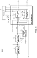
- Fig. 4 is a schematic block diagram of a moving object controller 2000 according to the example.
- the moving object controller 2000 of the example includes a landmark detection unit 2A and a candidate area obtaining unit 3A, which replace the landmark detection unit 2 and the candidate area obtaining unit 3 included in the moving object controller 1000 of the first embodiment, respectively.
- the landmark detection unit 2A extracts an image region including a landmark at time t from an image (image data) captured by the imaging device incorporating the distance sensor (not shown), which is mounted on the robot Rbtl.
- the landmark detection unit 2A outputs the extracted image to the candidate area obtaining unit 3 as an image D1_img.
- the landmark detection unit 2A also outputs the landmark detection signal LMt to the candidate area obtaining unit 3A, the state update unit 41, and the environmental map update unit 42.
- the candidate area obtaining unit 3A receives the landmark detection signal LMt and the image D1_img, which are output from the landmark detection unit 2A.
- the candidate area obtaining unit 3A also receives landmark pattern information LM_ptn.
- the landmark pattern information LM_ptn is predetermined information indicating a pattern (color or pattern) on the surface of a landmark in an environment in which the robot Rbtl moves.
- the candidate area obtaining unit 3 Based on the landmark pattern information LM_ptn and the image Dl_img, the candidate area obtaining unit 3 obtains robot position candidate information Cdtt, which is used to estimate a candidate for the position of the robot Rbtl at the current time.
- the candidate area obtaining unit 3A outputs the obtained robot position candidate information Cdtt to the state update unit 41 included in the state estimation unit 4.
- the landmark (one example) used in this example is cylindrical and long.
- the surface of the landmark includes two areas, (1) a first pattern area having a first pattern, and (2) a second pattern area having a second pattern.
- the first pattern area is one semicircular surface area at the circumference
- the second pattern area is the other semicircular surface area at the circumference.
- the shape and the surface patterns of the landmark are not limited to the above example.
- the landmark may have any other shape and/or pattern that allows the moving object controller 2000 detecting the landmark to determine the positional relationship between the moving object (the robot Rbtl) and the landmark (or information that may be used to determine the direction in which the landmark is observed) by recognizing (identifying) the shape and/or pattern of the landmark.
- Fig. 5 is a diagram showing the positional relationship between a candidate area AR_C1 for the position of the robot Rbtl at time t and a landmark LM2 used in the present example (viewed from above).
- Fig. 5 further schematically shows an image (image data) D1_img1 captured at time t by the imaging device incorporating the distance sensor (not shown), which is mounted on the robot Rbtl.
- the image D1_img1 is an image (image data) output from the landmark detection unit 2A to the candidate area obtaining unit 3A.
- the candidate area obtaining unit 3A analyzes the image D1_img1 shown in Fig. 5 based on the landmark pattern information LM_ptn for the landmark LM2. More specifically, the candidate area obtaining unit 3A determines that one semicircular surface area at the circumference of the landmark LM2 viewed from above is the first pattern area (with a solid black pattern) (an area indicated by ptn1 (LM2) in Fig. 5 ), and the other semicircular surface area at the circumference of the landmark LM2 viewed from above is the second pattern area (with an all-white pattern) (an area indicated by ptn2 (LM2) in Fig. 5 ) based on the landmark pattern information LM_ptn for the landmark LM2.
- the first pattern area with a solid black pattern
- LM2 an all-white pattern
- the candidate area obtaining unit 3A recognizes the first pattern area (with a solid black pattern) and the second pattern area (with an all-white pattern) around the center of the landmark in the image D1_img1, and determines that the first pattern area (with a solid black pattern) is on the left and the second pattern area (with an all-white pattern) is on the right. Based on these image analysis results, the candidate area obtaining unit 3A determines the candidate area AR_C1 for the position at which the captured image D1_img1 is obtained by the imaging device.
- the candidate area obtaining unit 3A determines the candidate area AR_C1 for the position of the robot Rbtl at time t as an area that is away from the position of the landmark LM2 (center point) by a distance d2 in the negative direction of y-axis along a line extending from the center point of the landmark LM2 toward the boundary point between the first pattern area ptn1 (LM2) and the second pattern area ptn2 (LM2) of the landmark LM2 viewed from above as shown in Fig. 5 .
- the candidate area obtaining unit 3A obtains the distance d2 between the landmark LM2 and the robot Rbtl based on the landmark detection signal LM t .
- the candidate area obtaining unit 3A generates robot position candidate information Cdtt including the information about the obtained candidate area AR_C1 for the position of the robot Rbtl at time t, and outputs the robot position candidate information Cdtt to the state update unit 41.
- the state update unit 41 determines that the position of the robot Rbtl at time t is likely to be the candidate area AR_C1, and updates the internal state data corresponding to the position of the robot Rbtl.
- Fig. 6 is a diagram showing the positional relationship between a candidate area AR C2 for the position of the robot Rbtl at time t and the landmark LM2 used in the present example (viewed from above).
- Fig. 6 further schematically shows an image (image data) D1_img2 captured at time t by the imaging device incorporating the distance sensor (not shown), which is mounted on the robot Rbtl.
- the image Dl_img2 is an image (image data) output from the landmark detection unit 2A to the candidate area obtaining unit 3A.
- the candidate area obtaining unit 3A analyzes the image D1_img2 shown in Fig. 6 based on the landmark pattern information LM_ptn for the landmark LM2. More specifically, the candidate area obtaining unit 3A determines that one semicircular surface area at the circumference of the landmark LM2 viewed from above is the first pattern area (with a solid black pattern) (an area indicated by ptn1 (LM2) in Fig. 6 ), and the other semicircular surface area at the circumference of the landmark LM2 viewed from above is the second pattern area (with an all-white pattern) (an area indicated by ptn2 (LM2) in Fig. 6 ) based on the landmark pattern information LM_ptn for the landmark LM2.
- the first pattern area with a solid black pattern
- LM2 an all-white pattern
- the candidate area obtaining unit 3A recognizes the first pattern area (with a solid black pattern) and the second pattern area (with an all-white pattern) around the center of the landmark in the image D1_img2, and determines that the first pattern area (with a solid black pattern) is on the right and the second pattern area (with an all-white pattern) is on the left. Based on these image analysis results, the candidate area obtaining unit 3A determines the candidate area AR_C2 for the position at which the captured image D1_img2 is obtained by the imaging device.
- the candidate area obtaining unit 3A determines the candidate area AR_C2 for the position of the robot Rbtl at time t as an area that is away from the position of the landmark LM2 (center point) by a distance d2 in the positive direction of y-axis along a line extending from the center point of the landmark LM2 toward the boundary point between the first pattern area ptn1 (LM2) and the second pattern area ptn2 (LM2) of the landmark LM2 viewed from above as shown in Fig. 6 .
- the candidate area obtaining unit 3A obtains the distance d2 between the landmark LM2 and the robot Rbtl based on the landmark detection signal LMt.
- the candidate area obtaining unit 3A generates the robot position candidate information Cdtt including the information about the obtained candidate area AR_C2 for the position of the robot Rbtl at time t, and outputs the robot position candidate information Cdtt to the state update unit 41.
- the state update unit 41 determines that the position of the robot Rbtl at time t is likely to be the candidate area AR_C2, and updates the internal state data corresponding to the position of the robot Rbtl.
- Fig. 7 is a diagram showing the positional relationship between a candidate area AR_C3 for the position of the robot Rbtl at time t and a landmark LM2 used in the present example (viewed from above).
- Fig. 7 further schematically shows an image (image data) D1_img3 captured at time t by the imaging device incorporating the distance sensor (not shown), which is mounted on the robot Rbtl.
- the image Dl_img3 is an image (image data) output from the landmark detection unit 2A to the candidate area obtaining unit 3A.
- the candidate area obtaining unit 3A analyzes the image D1_img3 shown in Fig. 7 based on the landmark pattern information LM_ptn for the landmark LM2. More specifically, the candidate area obtaining unit 3A determines that one semicircular surface area at the circumference of the landmark LM2 viewed from above is the first pattern area (with a solid black pattern) (an area indicated by ptn1 (LM2) in Fig. 7 ), and the other semicircular surface area at the circumference of the landmark LM2 viewed from above is the second pattern area (with an all-white pattern) (an area indicated by ptn2 (LM2) in Fig. 7 ) based on the landmark pattern information LM_ptn for the landmark LM2.
- the first pattern area with a solid black pattern
- LM2 an all-white pattern
- the candidate area obtaining unit 3A determines only the second pattern area (with an all-white pattern) of the landmark LM2 in the image D1_img3. Based on these image analysis results, the candidate area obtaining unit 3A determines the candidate area AR_C3 for the position at which the captured image Dl_img3 is obtained by the imaging device.
- the candidate area obtaining unit 3A determines the candidate area AR_C3 for the position of the robot Rbtl at time t as an area that is away from the position of the landmark LM2 (center point) by a distance d2 in the positive direction of x-axis along a line extending from the center point of the landmark LM2 toward substantially the middle point, along the circumference, of the second pattern area ptn2 (LM2) of the landmark LM2 viewed from above as shown in Fig. 7 .
- the candidate area obtaining unit 3A obtains the distance d2 between the landmark LM2 and the robot Rbtl based on the landmark detection signal LM t .
- the candidate area obtaining unit 3A generates the robot position candidate information Cdtt including the information about the obtained candidate area AR_C3 for the position of the robot Rbtl at time t, and outputs the robot position candidate information Cdtt to the state update unit 41.
- the state update unit 41 determines that the position of the robot Rbtl at time t is likely to be the candidate area AR_C3, and updates the internal state data corresponding to the position of the robot Rbtl.
- Fig. 8 is a diagram showing the positional relationship between a candidate area AR_C4 for the position of the robot Rbtl at time t and a landmark LM2 used in the present example (viewed from above).
- Fig. 8 further schematically shows an image (image data) D1_img4 captured at time t by the imaging device incorporating the distance sensor (not shown), which is mounted on the robot Rbtl.
- the image D1_img4 is an image (image data) output from the landmark detection unit 2A to the candidate area obtaining unit 3A.
- the candidate area obtaining unit 3A analyzes the image Dl_img4 shown in Fig. 8 based on the landmark pattern information LM_ptn for the landmark LM2. More specifically, the candidate area obtaining unit 3A determines that one semicircular surface area at the circumference of the landmark LM2 viewed from above is the first pattern area (with a solid black pattern) (an area indicated by ptn1 (LM2) in Fig. 8 ), and the other semicircular surface area at the circumference of the landmark LM2 viewed from above is the second pattern area (with an all-white pattern) (an area indicated by ptn2 (LM2) in Fig. 8 ) based on the landmark pattern information LM_ptn for the landmark LM2.
- the first pattern area with a solid black pattern
- LM2 an all-white pattern
- the candidate area obtaining unit 3A recognizes only the first pattern area (with a solid black pattern) around the center of the landmark in the image D1_img4. Based on these image analysis results, the candidate area obtaining unit 3A determines the candidate area AR_C4 for the position at which the captured image D1_img4 is obtained by the imaging device.
- the candidate area obtaining unit 3A determines the candidate area AR_C4 for the position of the robot Rbtl at time t as an area that is away from the position of the landmark LM2 (center point) by a distance d2 in the negative direction of x-axis along a line extending from the center point of the landmark LM2 toward substantially the middle point, along the circumference, of the second pattern area ptn2 (LM2) of the landmark LM2 viewed from above as shown in Fig. 8 .
- the candidate area obtaining unit 3A obtains the distance d2 between the landmark LM2 and the robot Rbtl based on the landmark detection signal LMt.
- the candidate area obtaining unit 3A generates robot position candidate information Cdtt including the information about the obtained candidate area AR_C4 for the position of the robot Rbtl at time t, and outputs the robot position candidate information Cdtt to the state update unit 41.
- the state update unit 41 determines that the position of the robot Rbtl at time t is likely to be the candidate area AR_C4, and updates the internal state data corresponding to the position of the robot Rbtl.
- Fig. 9 is a diagram showing the positional relationship between a candidate area AR_C5 for the position of the robot Rbtl at time t and a landmark LM2 used in the present example (viewed from above).
- Fig. 9 further schematically shows an image (image data) D1_img5 captured at time t by the imaging device incorporating the distance sensor (not shown), which is mounted on the robot Rbtl.
- the image D1_img5 is an image (image data) output from the landmark detection unit 2A to the candidate area obtaining unit 3A.
- the candidate area obtaining unit 3A analyzes the image Dl_img5 shown in Fig. 9 based on the landmark pattern information LM_ptn for the landmark LM2. More specifically, the candidate area obtaining unit 3A determines that one semicircular surface area at the circumference of the landmark LM2 viewed from above is the first pattern area (with a solid black pattern) (an area indicated by ptn1 (LM2) in Fig. 9 ), and the other semicircular surface area at the circumference of the landmark LM2 viewed from above is the second pattern area (with an all-white pattern) (an area indicated by ptn2 (LM2) in Fig. 9 ) based on the landmark pattern information LM_ptn for the landmark LM2.
- the first pattern area with a solid black pattern
- LM2 an all-white pattern
- the candidate area obtaining unit 3A recognizes the first pattern area (with a solid black pattern) and the second pattern area (with an all-white pattern) in a left area of the landmark in the image D1_img5, and determines that the first pattern area (with a solid black pattern) is on the left and the second pattern area (with an all-white pattern) is on the right.
- the candidate area obtaining unit 3A also determines the proportion of the first pattern area and the proportion of the second pattern area in the horizontal direction of the image. Based on these image analysis results, the candidate area obtaining unit 3A determines the candidate area AR_C5 for the position at which the captured image Dl_img5 is obtained by the imaging device.
- the candidate area obtaining unit 3A determines a point that is away from the position of the landmark LM2 (center point) by the distance d2 and from which the landmark appears in the same manner as in the image Dl_img5 as viewed from above in Fig. 9 .
- an area that is away from the center point of the landmark LM2 by the distance d2 in an obliquely downward direction of a line extending from the center point of the landmark LM2 toward a point A1 in Fig. 9 is determined as the candidate area AR_C5 for the position of the robot Rbtl at time t as viewed from above.
- the candidate area obtaining unit 3A obtains the distance d2 between the landmark LM2 and the robot Rbtl based on the landmark detection signal LM t .
- the candidate area obtaining unit 3A generates robot position candidate information Cdtt including the information about the obtained candidate area AR_C5 for the position of the robot Rbtl at time t, and outputs the robot position candidate information Cdtt to the state update unit 41.
- the state update unit 41 determines that the position of the robot Rbtl at time t is likely to be the candidate area AR_C5, and updates the internal state data corresponding to the position of the robot Rbtl.
- the moving object controller 2000 obtains a captured image of a landmark having a predetermined pattern as actual observation data, and analyzes the appearance of the landmark in the captured image.
- the moving object controller 2000 can thus estimate the position of the moving object (robot Rbtl) with high accuracy, and can perform a highly accurate state estimation process at high speed in an appropriate manner.
- the moving object controller 2000 can control the moving object (the robot Rbtl) in an appropriate manner.
- the moving object controller 2000 can also estimate the position of the robot Rbtl with high accuracy at high speed simply by obtaining the distance between a landmark and the robot Rbtl.
- the moving object controller 2000 can thus perform an estimation process involving less calculations without complicated processing using many internal state variables.
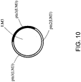
- the landmark in the present example has the first pattern area (with a solid black pattern) and the second pattern area (with an all-white pattern), the landmark may have another number of patterns.
- a landmark LM3 shown in Fig. 10 has three patterns, namely, a first pattern area (pattern ptn1 (LM3) in Fig. 10 ), a second pattern area (pattern ptn2 (LM3) in Fig. 10 ), and a pattern ptn3 (LM3) in Fig. 10 as viewed from above.
- the landmark may have four or more patterns.
- the imaging device incorporating the distance sensor mounted on the robot Rbtl obtains a colored captured image and a distance image in the above embodiment
- the embodiment may not be limited to this structure.
- a stereoscopic camera mounted on the robot Rbtl may capture two images that are used to obtain a distance image.
- a distance sensor such as a range finder, may be mounted on the robot Rbtl to measure the distance to a landmark.
- a plurality of sensors may be mounted on the robot Rbtl to obtain signals that are used to obtain actual observation data.
- x-y coordinates are set for generating environmental map data as shown in Figs. 2 and 3 and Figs. 5 to 9 in the above embodiment and example, the embodiment may not be limited to this.
- polar coordinates may be used.
- absolute coordinates are used in the above embodiment, the embodiment should not be limited to this.
- the processing in the above embodiment may be performed using relative coordinates with the position of the robot Rbtl as the origin.
- the position of the moving object (the robot Rbtl) and the positions of the landmarks are defined using two-dimensional data (x-coordinate and y-coordinate values) in the above embodiment, the embodiment should not be limited to this example.
- the position of the moving object (the robot Rbtl) and the positions of the landmarks may also be determined using three-dimensional data (e.g., x-coordinate, y-coordinate, and z-coordinate values).
- a candidate position for the robot Rbtl at time t is on a circle formed by the intersection of a sphere with a radius d1A t centered on the landmark LM1A and a sphere with a radius d1B t centered on the landmark LM1B.
- Each block of the moving object controller described in the above embodiment may be formed using a single chip with a semiconductor device, such as an LSI (large-scale integration) device, or some or all of the blocks of the moving object controller may be formed using a single chip.
- a semiconductor device such as an LSI (large-scale integration) device
- LSI is used as the semiconductor device technology
- the technology may be an integrated circuit (IC), a system LSI, a super LSI, or an ultra LSI depending on the degree of integration of the circuit.
- the circuit integration technology employed should not be limited to LSI, but the circuit integration may be achieved using a dedicated circuit or a general-purpose processor.
- FPGA field programmable gate array
- reconfigurable processor which is an LSI circuit in which internal circuit cells are reconfigurable or more specifically the internal circuit cells can be reconnected or reset, may be used.
- All or part of the processes performed by the functional blocks described in the above embodiment may be implemented using programs. All or part of the processes performed by the functional blocks described in the above embodiment may be implemented by a central processing unit (CPU), a microprocessor, and a processor in a computer.
- the programs for these processes may be stored in a storage device, such as a hard disk or a ROM, and may be executed from the ROM or be read into a RAM and then executed.
- the processes described in the above embodiment may be implemented by using either hardware or software (including use of an operating system (OS), middleware, or a predetermined library), or may be implemented using both software and hardware.
- OS operating system
- middleware middleware
- predetermined library a predetermined library
- the present invention may also include a computer program enabling a computer to implement the method described in the above embodiments and a computer readable recording medium on which such a program is recorded.
- the computer readable recording medium may be, for example, a flexible disk, a hard disk, a CD-ROM, an MO, a DVD, a DVD-ROM, a DVD-RAM, a large-capacity DVD, a next-generation DVD, or a semiconductor memory.
- the computer program may not be recorded on the recording medium but may be transmitted with an electric communication line, a radio or cable communication line, or a network such as the Internet.
- unit herein may include “circuitry,” which may be partly or entirely implemented by using either hardware or software, or both hardware and software.
Description
- The present invention relates to a technique for controlling a moving object using simultaneous localization and mapping (SLAM).
- Using simultaneous localization and mapping (SLAM), a moving object, such as an autonomous robot, estimates its position and simultaneously generates an environmental map while moving autonomously.
- A robot (moving object) that moves autonomously with SLAM generates an environmental map around the robot using observation data obtained with a sensor mounted on the robot and using inputs for controlling the robot, while estimating the position and the posture of the robot in the generated environmental map. More specifically, the robot estimates its position and posture Xt (or X1:t = {X1, X2, ... , Xt}) and obtains an environmental map m using a control input sequence U1:t = {U1, U2, ... , Ut} and an observation sequence Z1:t = {Z1, Z2, ... , Zt} in the state space model where the robot follows the system model xt ~ g (xt|xt-1, Ut) (Ut is a control input) and the observation follows the observation model Zt ~ h (Zt|xt, m) (m is an environmental map).
- Techniques have been developed to estimate the posture of a robot with high accuracy using particle filters (e.g.,
Japanese Unexamined Patent Application Publication No. 2008-126401 - A sensor used to obtain observation data may typically be an RGB camera incorporating a visible light image sensor, or a range finder that obtains distance information using infrared light or laser light. Two or more different sensors may be used in combination to obtain observation data.
- A robot (moving object) that moves autonomously with SLAM typically generates a topological environmental map, instead of generating a geometric environmental map. The environmental map is obtained using, for example, information about landmarks. In this case, the environmental map contains a plurality of sets of landmark information. Each landmark has parameters including variance-covariance matrices expressing (1) information about the position of the landmark and (2) the uncertainty of positional information for the landmark.
- When the robot that moves autonomously with SLAM incorporates an RGB camera as its sensor, the robot uses, as landmarks, points or lines with features or objects with distinguishable markers. The robot detects (identifies) an image region corresponding to a landmark in an image captured by the RGB camera to obtain information about the landmark. In this case, the actual position of the robot relative to the actual position of the landmark is determined using the image obtained by the RGB camera, and observation data at the current time is obtained based on the identification result.
- When the position of a landmark is obtained from an image captured by the RGB camera as described above, the actual position of the robot and the actual position of the landmark may not be easily estimated with high accuracy. The RGB camera or the range finder has high directivity and thus has a limited observable range. Of many landmarks arranged around the robot, a small number of landmarks can be detected at a time based on data obtained by the RGB camera or the range finder. For example, (1) the distance from the robot to a detected landmark and (2) the angle formed by a predetermined reference axis and a straight line connecting the robot and the detected landmark as viewed from above an environment in which the robot moves are obtained as information about a landmark. In this case, the position of the robot may not be estimated with high accuracy based on the obtained landmark information.
This is because all points on the circumference of a circle centered on the position of the detected landmark and having its radius being a distance from the robot to the detected landmark can be candidates for the position of the robot. More specifically, such many candidates for the position of the robot increase the amount of processing to estimate the position of the robot at the current time. In this case, the position of the robot cannot be easily estimated with high accuracy. When the position of the robot cannot be estimated with high accuracy, the error between the actual internal state of the robot and the estimated internal state of the robot increases, and may disable the robot (moving object) from moving autonomously in a stable manner. - Document
US 2005/182518 A1 describes a method in a visual simultaneous localization and mapping (VSLAM) system of updating a map in a robust manner, the method comprising: using visual features to recognize landmarks in an environment; maintaining the map of the visually-recognized landmarks, where the map comprises landmark poses associated with landmarks; receiving an indication that a new landmark has been observed; retrieving dead reckoning measurements observed from a prior pose; receiving an indication of whether the dead reckoning measurements are trustworthy; at least partially in response to determining that the dead reckoning measurements are trustworthy, then performing: using the dead reckoning measurements and the prior pose to compute a landmark pose for the new landmark L; associating the computed landmark pose with the new landmark; and storing the landmark pose and the association to the new landmark L to update the map; and, at least partially in response to determining that the dead reckoning measurements are not trustworthy, then not updating the, map with the new landmark. - Document
US 2010/215216 A1 describes a localization system and method to recognize the location of an autonomous mobile platform. In order to recognize the location of the autonomous mobile platform, a beacon (three-dimensional structure) having a recognizable image pattern is disposed at a location desired by a user, the mobile platform which knows image pattern information of the beacon photographs the image of the beacon and finds and analyzes a pattern to be recognized from the photographed image. A relative distance and a relative angle of the mobile platform are computed using the analysis of the pattern such that the location of the mobile platform is accurately recognized. - Document
US 2004/239756 A1 describes techniques for computing error-bounded position and orientation (pose) of a panoramic camera in real-world environments. Such environments comprise large interior spaces (e.g., buildings), wherein a space comprises multiple rooms. A technique for capturing images associated with an environment comprises the following steps/operations. First, respective placements of fiducials in the environment are determined so as to satisfy at least one constraint. Images are captured, with an image capture device (e.g., camera), associated with the environment with the fiducials placed therein. A pose estimation of the image capture device is then determined based on projections of the fiducials in the captured images. The pose estimation is optimized so as to obtain an optimal pose per image. Also, the fiducial placements are optimized so as to obtain optimal fiducial placements. Then at least one constraint comprises a constraint associated with the number of visible fiducials, a constraint associated with a distance from a viewpoint to a fiducial, and/or a constraint associated with an angle subtended by pairs of fiducials. - In response to the above problems, it is an object of the present invention to provide a moving object controller and a program for controlling a moving object in an appropriate manner by estimating the position of the moving object (robot) accurately based on landmark information and performing a highly accurate state estimation process at high speed in an appropriate manner, and also to provide a landmark used with the controller and the program. The object is solved by the features of the independent claims.
-
-
Fig. 1 is a schematic block diagram of amoving object controller 1000 according to a first embodiment. -
Fig. 2 is a diagram showing the positional relationship between candidate points C1t and C2t for the position of a robot Rbtl at time t, and a set of landmarks LM1A and LM1B (viewed from above). -
Fig. 3 is a diagram showing the positional relationship between candidate points C1t+1 and C2t+1 for the position of the robot Rbtl at time t+1, and the set of landmarks LM1A and LM1B (viewed from above). -
Fig. 4 is a schematic block diagram of amoving object controller 2000 according to an example useful for understanding the invention. -
Fig. 5 is a diagram showing the positional relationship between a candidate area AR_C1 for the position of the robot Rbtl at time t and a landmark LM2 in the example (viewed from above), and also schematically shows an image (image data) D1_img1 captured at time t by an imaging device incorporating a distance sensor (not shown), which is mounted on the robot Rbtl. -
Fig. 6 is a diagram showing the positional relationship between a candidate area AR_C2 for the position of the robot Rbtl at time t and the landmark LM2 in the example (viewed from above), and also schematically shows an image (image data) Dl_img2 captured at time t by the imaging device incorporating the distance sensor (not shown), which is mounted on the robot Rbt1. -
Fig. 7 is a diagram showing the positional relationship between a candidate area AR_C3 for the position of the robot Rbtl at time t and the landmark LM2 in the example (viewed from above), and also schematically shows an image (image data) Dl_img3 captured at time t by the imaging device incorporating the distance sensor (not shown), which is mounted on the robot Rbtl. -
Fig. 8 is a diagram showing the positional relationship between a candidate area AR_C4 for the position of the robot Rbtl at time t and the landmark LM2 in the example (viewed from above), and also schematically shows an image (image data) D1_img4 captured at time t by the imaging device incorporating the distance sensor (not shown), which is mounted on the robot Rbtl. -
Fig. 9 is a diagram showing the positional relationship between a candidate area AR_C5 for the position of the robot Rbtl at time t and the landmark LM2 in the example (viewed from above), and also schematically shows an image (image data) Dl_img5 captured at time t by the imaging device incorporating the distance sensor (not shown), which is mounted on the robot Rbtl. -
Fig. 10 schematically shows a landmark LM3 (viewed from above). - A first embodiment will now be described with reference to the drawings.
-
Fig. 1 is a schematic block diagram of amoving object controller 1000 according to a first embodiment. - The
moving object controller 1000 is mounted on a moving object, such as an autonomous robot Rbtl (not shown). - As shown in
Fig. 1 , themoving object controller 1000 includes anobservation obtaining unit 1, alandmark detection unit 2, a candidatearea obtaining unit 3, astate estimation unit 4, and astorage unit 5. - For ease of explanation, observation data D1 obtained by the
observation obtaining unit 1 includes an image (image data) captured by an imaging device incorporating a distance sensor (not shown), which is mounted on the moving object (robot Rbtl), and a distance image (distance data) obtained by the imaging device incorporating the distance sensor. - The
observation obtaining unit 1 receives data obtained by the imaging device incorporating the distance sensor (not shown), which is mounted on the moving object (robot Rbtl), as input data Din. Theobservation obtaining unit 1 obtains the observation data D1, which includes an image (image data) D1_img and a distance image (distance data) D1_d, based on the input data Din. Theobservation obtaining unit 1 outputs the obtained observation data D1 to thelandmark detection unit 2 and astate update unit 41 included in thestate estimation unit 4. - The
landmark detection unit 2 receives the observation data D1, which is output from theobservation obtaining unit 1. Thelandmark detection unit 2 obtains information about the distance and the direction (angle) from the robot Rbtl to a landmark based on the observation data D1 (the image data D1_img and the distance image D1_d). Thelandmark detection unit 2 outputs a signal including the obtained information to the candidatearea obtaining unit 3, and thestate update unit 41 and an environmentalmap update unit 42 included in thestate estimation unit 4 as a landmark detection signal LMt. - The candidate
area obtaining unit 3 receives the landmark detection signal LMt output from thelandmark detection unit 2. Based on the landmark detection signal LMt, the candidatearea obtaining unit 3 obtains robot position candidate information Cdtt, which is used to estimate the candidate position for the position of the robot Rbtl at the current time. The candidatearea obtaining unit 3 outputs the obtained robot position candidate information Cdtt to thestate update unit 41 included in thestate estimation unit 4. - As shown in
Fig. 1 , thestate estimation unit 4 includes thestate update unit 41 and the environmentalmap update unit 42. - The
state update unit 41 receives observation data D1, which is output from theobservation obtaining unit 1, a landmark detection signal LMt, which is output from thelandmark detection unit 2, robot position candidate information Cdtt, which is output from the candidatearea obtaining unit 3, control input data Ut for the moving object (robot Rbtl), and internal state data Xt-1 indicating the internal state of the moving object (robot Rbtl) at time t-1, which is read from thestorage unit 5. Thestate update unit 41 estimates the internal state of the robot Rbtl based on the observation data D1, the landmark detection signal LMt, the robot position candidate information Cdtt, the control input data Ut, and the internal state data Xt-1 of the robot Rbtl at time t-1 to obtain the estimation result as the internal state data Xt of the moving object at the current time t (update the internal state data). Thestate update unit 41 then outputs the obtained internal state data Xt of the moving object at the current time t out of thestate estimation unit 4, and also to thestorage unit 5. The internal state data Xt externally output from thestate estimation unit 4 is used by, for example, a function unit (central control unit) that centrally controls the moving object (automatically moving robot Rbtl) (not shown) as data to control the moving object (automatically moving robot Rbtl). - The
state update unit 41 also outputs the internal state data Xt corresponding to the position of the robot Rbtl at the current time t to the environmentalmap update unit 42. - The
state update unit 41 also outputs the control input data Ut for the robot Rbtl at the current time t to thestorage unit 5. - The environmental
map update unit 42 receives a landmark detection signal LMt ,which is output from thelandmark detection unit 2, environmental map data mt-1 at time t-1, which is read from thestorage unit 5, and internal state data Xt of the robot Rbtl at the current time t, which is output from thestate update unit 41. The environmentalmap update unit 42 obtains information about a detected landmark based on the landmark detection signal LMt, and updates the environmental map data based on the obtained landmark information, the environmental map data mt-1 at time t-1, and the internal state data Xt of the robot Rbtl at the current time t to obtain environmental map data mt at the current time t. The environmentalmap update unit 42 then outputs the updated environmental map data mt out of thestate estimation unit 4, and also to thestorage unit 5. The environmental map data mt externally output from thestate estimation unit 4 is used by, for example, a function unit (central control unit) that centrally controls the moving object (automatically moving robot Rbtl) (not shown) as data to control the moving object (automatically moving robot Rbtl). - The
storage unit 5 receives and stores internal state data Xt of the moving object at the current time t and control input data Ut, which are output from thestate update unit 41 included in thestate estimation unit 4, and environmental map data mt. The data stored in thestorage unit 5 is read by thestate estimation unit 4 at predetermined timing. Thestorage unit 5 can store a plurality of sets of internal state data and environmental map data obtained at a plurality of times. - The data at the current time t refers to data obtained using the target observation data D1 by the moving object controller 1000 (internal state data Xt of the moving object and environmental map data mt). The data at time t-1 preceding the current time t by one time refers to data obtained by the moving
object controller 1000 at the time preceding the current time t by one time (internal state data Xt-1 of the moving object and environmental map data mt-1). The data at time t-k preceding the current time t by k times (k is a natural number) refers to data obtained by the movingobject controller 1000 at the time preceding the current time t by k times (internal state data Xt-k of the moving object and environmental map data mt-k). - The above data may be obtained at synchronous timing or at asynchronous timing.
- 1.2 Operation of Moving Object Controller
- The operation of the moving
object controller 1000 with the above-described structure will now be described. - In the example described below, the robot Rbtl is a moving object that moves autonomously. The input data Din is an image (captured image) captured by an imaging device incorporating a visible image sensor and a distance sensor (not shown), which is mounted on the robot Rbtl, and a distance image (distance data). The environmental map is generated based on information about landmarks.
- To allow the moving
object controller 1000 to generate an environmental map, landmark sets each including two landmarks are arranged in an environment in which the robot Rbtl moves. Each set of landmarks is provided with information such as a color code or a specific pattern to differentiate from other sets of landmarks. This information is used to identify a set (landmark set) including a detected landmark. -
Fig. 2 is a diagram showing the positional relationship between candidate points C1t and C2t for the position of the robot Rbtl at time t, and a set of landmarks LM1A and LM1B (viewed from above). InFig. 2 , the space is defined by x-axis and y-axis, and the origin indicated by 0. For ease of explanation, the processing performed by the moving object controller will be described based on the positional relationship between the robot Rbtl and the landmarks LM1A and LM1B on a two-dimensional plane (x-y plane) as shown inFig. 2 . However, the moving object controller may perform the processing based on the positional relationship between the robot Rbtl and the landmarks LM1A and LM1B in a three-dimensional space. -
Fig. 3 is a diagram showing the positional relationship between candidate points C1t+1 and C2t+1 for the position of the robot Rbtl attime t+ 1, and a set of landmarks LM1A and LM1B (viewed from above). InFig. 3 , the space is also defined by x-axis and y-axis, and the origin indicated by 0 as inFig. 2 . - In the example described below, the robot Rbtl at time t at the position indicated by the point C1t in
Fig. 2 receives control data for moving the robot in the direction of arrow Dirl shown inFig. 3 . Attime t+ 1, the robot Rbtl moves to the position indicated by the point C1t+1 inFig. 3 . - The moving
object controller 1000 uses (1) data indicating the internal state of the robot Rbtl and (2) data representing an environmental map described below. - The moving
object controller 1000 sets, as data indicating the internal state of the robot Rbtl, the internal state data Xt indicating the position and the angle of the robot Rbtl at time t. - The internal state data Xt indicating the position and the angle of the robot Rbtl at time t is a three-dimensional state vector written as

- y0t is an expected value of the y coordinate of the robot Rbtl at time t, and
- θt is an expected value of the angle of the robot Rbtl (the orientation of the robot Rbtl) with respect to the positive direction of x-axis at time t.
- The moving
object controller 1000 uses particle filtering (Monte Carlo approximation) to estimate the internal state of the robot Rbtl. - In particle filtering, the posterior probability distribution of a state vector Xt-1 at time t-1 is used as the prior probability distribution of the state vector Xt at the current time t, and the predictive probability distribution of the state vector Xt at the current time t is obtained through prediction using the prior probability distribution of the state vector Xt at the current time t. A likelihood is then calculated based on the obtained predictive probability distribution and actual observation data (observation data at the current time t). At the ratio proportional to the calculated likelihood, particles are sampled without changing the total number of the particles. Through the processing described above, the internal state of the robot Rbtl is estimated.
- In this manner, the moving
object controller 1000 sets the data Xt indicating the internal state of the robot Rbtl. - The moving
object controller 1000 sets environmental map data mt at time t as data representing an environmental map. - The environmental map data mt includes information about landmarks. When the robot Rbtl detects a landmark, information about the detected landmark is added to the environmental map data mt.
- The moving
object controller 1000 sets the environmental map data mt at time t written as
- In this formula, LMkAPt is internal state data corresponding to the position of one landmark included in the k-th landmark set at time t, and LMkBPt is the internal state data corresponding to the position of the other landmark included in the k-th landmark set at time t. One landmark set includes two landmarks.
- More specifically, the moving
object controller 1000 determines the set of internal state data for 2 × k landmarks included in k landmark sets as the environmental map data mt at time t. - In the example shown in
Fig. 2 , the environmental map data mt includes information about the two landmarks LM1A and LM1B included in one landmark set. In the example shown inFig. 2 , the environmental map data mt is written as
- Information LM1APt about the landmark LM1A and information LM1BPt about the landmark LM1B (the internal state data corresponding to the landmark positions) are set in the manner described below.
- For the landmark LM1A,

θ1At is an angle formed by x-axis and a straight line connecting the robot Rbtl and the landmark LM1A as viewed from above. - For the landmark LM1B,

θ1Bt is an angle formed by x-axis and a straight line connecting the robot Rbtl and the landmark LM1B as viewed from above. - For ease of explanation, the robot Rbtl incorporating the moving
object controller 1000 in the example described below obtains the internal state data of the robot Rbtl and environmental map data based on the two landmarks LMA1 and LMB1 included in one landmark set as shown inFigs. 2 and3 . - The processing of the moving
object controller 1000 will now be described in detail. - At time t, the robot Rbtl and the landmarks LM1A and LM1B are positioned as shown in
Fig. 2 . The imaging device incorporating the distance sensor, which is mounted on the movingobject controller 1000, captures an captured image (image data) of an area ARcp shown inFig. 2 and obtains a distance image (distance data). - The
observation obtaining unit 1 obtains the observation data D1, which includes the image (image data) D1_img of the area Arcp and the distance image (distance data) D1_d, from the input data Din received from the imaging device incorporating the distance sensor mounted on the movingobject controller 1000. Theobservation obtaining unit 1 outputs the obtained observation data D1 to thelandmark detection unit 2 and thestate update unit 41 included in thestate estimation unit 4. - The
landmark detection unit 2 obtains information about the distance and the direction (angle) from the robot Rbtl to the landmarks LM1A and LM1B from the observation data D1 (the image data D1_img and the distance image D1_d). More specifically, thelandmark detection unit 2 obtains the data LM1APt and the data LM1BPt described below. - For the landmark LM1A,

θ1At is an angle formed by x-axis and a straight line connecting the robot Rbtl and the landmark LM1A as viewed from above. - For the landmark LM1B,

θ1Bt is an angle formed by x-axis and a straight line connecting the robot Rbtl and the landmark LM1B as viewed from above. - A signal including the data LM1APt and the data LM1BPt obtained for the landmarks LM1A and LM1B are output as the landmark detection signal LMt from the
landmark detection unit 2 to the candidatearea obtaining unit 3, and thestate update unit 41 and the environmentalmap update unit 42 included in thestate estimation unit 4. - Based on the landmark detection signal LMt, the candidate
area obtaining unit 3 obtains information for estimating a candidate position of the robot Rbtl at the current time t. - More specifically, the candidate
area obtaining unit 3 determines two intersection points C1t and C2t of (1) a circle centered on the point LM1A with its radius being a distance d1At from the robot Rbtl to the landmark LM1A, and (2) a circle centered on the point LM1B with its radius being a distance d1Bt from the robot Rbtl to the landmark LM1B as shown inFig. 2 . The candidatearea obtaining unit 3 then outputs information about the two intersection points C1t and C2t (information for identifying the intersection points C1t and C2t) to thestate update unit 41 included in thestate estimation unit 4 as robot position candidate information Cdtt. - In some embodiments, the candidate
area obtaining unit 3 may perform processing considering errors and the estimation accuracy of the landmark positions (the accuracy of the internal state data corresponding to the landmarks) and output information about an area with a predetermined size including the two intersection points C1t and C2t to thestate update unit 41 included in thestate estimation unit 4 as the robot position candidate information Cdtt. - The
state update unit 41 included in thestate estimation unit 4 estimates the internal state of the robot Rbtl based on the observation data D1, the landmark detection signal LMt, the robot position candidate information Cdtt, the control input data Ut, and the internal state data Xt-1 of the robot Rbtl at time t-1 to obtain the estimation result as the internal state data Xt of the robot Rbtl at the current time t (update the internal state data). - More specifically, the
state update unit 41 estimates one of the points C1t and C2t, which are two candidates for the position of the robot Rbtl, as the position of the robot Rbtl at time t based on the robot position candidate information Cdtt. In the example below, thestate update unit 41 estimates the point C1t as the position of the robot Rbtl at time t. - The internal state data Xt of the robot Rbtl at time t obtained by the
state update unit 41 is output from thestate update unit 41 to thestorage unit 5, and is stored into thestorage unit 5. - The environmental
map update unit 42 obtains information about a detected landmark based on the landmark detection signal LMt, which is output from thelandmark detection unit 2. The environmentalmap update unit 42 updates the environmental map data based on the obtained landmark information, the environmental map data mt-1 at time t-1, and the internal state data Xt of the robot Rbtl at the current time t to obtain the environmental map data mt at the current time t. - More specifically, when the positional coordinates of the landmark LM1A at time t on the x-y plane are indicated by (x1At, y1At), and the positional coordinates of the landmark LM1B at time t on the x-y plane are by (x1Bt, y1Bt), the environmental
map update unit 42 obtains the positional coordinates (positional information) of the landmarks LM1A and LM1B at time t on the x-y plane using the formulae below:


- The environmental
map update unit 42 updates the environmental map data mt using the data obtained as described above. - At time t, the robot Rbtl also receives a control input Ut. In the example below, the control input Ut is control input data for moving the robot Rbtl in the direction of arrow Dir1 shown in
Fig. 3 . - When controlled using the control input data Ut at time t, the robot Rbtl is predicted to have moved to the position indicated by the point C1t+1 in
Fig. 3 or to the position indicated by the point C2_NGt+1 inFig. 3 attime t+ 1. - The
observation obtaining unit 1 obtains the observation data D1, which is the image (image data) D1_img of the area Arcp and the distance image (distance data) D1_d, from the input data Din received from the imaging device incorporating the distance sensor mounted on the movingobject controller 1000. Theobservation obtaining unit 1 then outputs the obtained observation data D1 to thelandmark detection unit 2 and thestate update unit 41 included in thestate estimation unit 4. - The
landmark detection unit 2 obtains information about the distance and the direction (angle) from the robot Rbtl to the landmarks LM1A and LM1B based on the observation data D1 (the image data D1_img and the distance image D1_d). More specifically, thelandmark detection unit 2 obtains the data LM1APt and the data LM1BPt described below. - For the landmark LM1A,

θ1At+1 is an angle formed by x-axis and a straight line connecting the robot Rbtl and the landmark LM1A as viewed from above. - For the landmark LM1B,

θ1Bt+1 is an angle formed by x-axis and a straight line connecting the robot Rbtl and the landmark LM1B as viewed from above. - A signal including the data LM1APt+1 and the LM1BPt+1 obtained for the landmarks LM1A and LM1B is output as the landmark detection signal LMt+1 from the
landmark detection unit 2 to the candidatearea obtaining unit 3, and thestate update unit 41 and the environmentalmap update unit 42 included in thestate estimation unit 4. - Based on the landmark detection signal LMt+1, the candidate
area obtaining unit 3 obtains information for estimating the candidate position for the position of the robot Rbtl at the currenttime t+ 1. - More specifically, as shown in
Fig. 3 , the candidatearea obtaining unit 3 determines the two intersection points C1t+1 and C2t+1 of (1) a circle centered on the point LM1A with its radius being a distance d1At+1 from the robot Rbtl to the landmark LM1A and (2) a circle centered on the point LM1B with its radius being a distance d1Bt+1 from the robot Rbtl to the landmark LM1B as shown inFig. 3 . The candidatearea obtaining unit 3 outputs information about the two intersection points C1t+1 and C2t+1 (information for identifying the intersection points C1t+1 and C2t+1) to thestate update unit 41 included in thestate estimation unit 4 as the robot position candidate information Cdtt+1. - In some embodiments, the candidate
area obtaining unit 3 may perform processing considering errors and the estimation accuracy of the landmark positions (the accuracy of the internal state data corresponding to the landmarks) and output information about an area with a predetermined sized including the two intersection points C1t+1 and C2t+1 to thestate update unit 41 included in thestate estimation unit 4 as the robot position candidate information Cdtt+1. - The
state update unit 41 included in thestate estimation unit 4 estimates the internal state of the robot Rbtl based on the observation data D1, the landmark detection signal LMt+1, the robot position candidate information Cdtt+1, the control input data Ut+1, and the internal state data Xt of the robot Rbtl at time t to obtain the estimation results as the internal state data Xt+1 of the robot Rbtl at the current time t+1 (update the internal state data). - More specifically, the
state update unit 41 estimates one of the points C1t+1 and C2t+1, which are two candidates for the position of the robot Rbtl, as the position of the robot Rbtl at time t+1 based on the robot position candidate information Cdtt+1. - The moving
object controller 1000 obtains (1) the points C1t and C2t as two candidate points for the position of the robot Rbtl at time t, and (2) the points C1t+1 and C2t+1 as two candidate points for the position of the robot Rbtl attime t+ 1. The control input Ut provided to the robot Rbtl at time t is data for moving the robot Rbtl in the direction of arrow Dir1 shown inFig. 3 . - The
state update unit 41 predicts that the robot Rbtl is at the point C1t+1 or the point C2 _NGt+1 inFig. 3 at time t based on the control input Ut provided to the robot Rbtl at time t and the two candidate points C1t and C2t for the position of the robot Rbtl at time t estimated by the moving object controller 1000 (prediction 1). - Based on actual observation performed at
time t+ 1, the distance between the robot Rbtl and the landmark LM1A at time t+1 is the distance d1At+1, and the distance between the robot Rbtl and the landmark LM2A is the distance d2At+1. Using this actual observation attime t+ 1, thestate update unit 41 predicts that the position of the robot Rbtl at time t+1 is the candidate point C1t+1 or the candidate point C2t+1 (prediction 2). - More specifically, the
state update unit 41 estimates that the point C1t+1, which is a candidate point for the position of the robot Rbtl at time t+1 predicted through both theprediction 1 and theprediction 2 described above, is the position of the robot Rbtl attime t+ 1. Thestate update unit 41 updates the internal state data, which is the coordinate data (x0At+1, y0At+1) corresponding to the position of the robot Rbtl attime t+ 1, using the coordinate information for the point C1t+1. - This internal state data Xt+1 of the robot Rbtl at time t+1 obtained by the
state update unit 41 is output from thestate update unit 41 to thestorage unit 5, and is stored into thestorage unit 5. - The environmental
map update unit 42 obtains information about the detected landmark based on the landmark detection signal LMt+1 output from thelandmark detection unit 2. The environmentalmap update unit 42 updates the environmental map data based on the obtained landmark information, the environmental map data mt at time t, and the internal state data Xt+1 of the robot Rbtl at the current time t+1 to obtain the environmental map data mt+1 at the currenttime t+ 1. - More specifically, when the positional coordinates of the landmark LM1A at time t+1 on the x-y plane are (x1At+1, y1At+1), and the positional coordinates of the landmark LM1B at time t+1 on the x-y plane are (x1Bt+1, y1Bt+1), the environmental
map update unit 42 obtains the positional coordinates (positional information) of the landmarks LM1A and LM1B at time t+1 on the x-y plane using the formulae below:


- The environmental
map update unit 42 updates the environmental map data mt+1 using the data obtained as described above. - The processing described above will be repeated at time t+2 and subsequent times.
- The moving
object controller 1000 uses a landmark set including two landmarks and measures the distance from the robot Rbtl to each of the two landmarks, and can thus narrow down the candidates for the position of the robot Rbtl to fewer points (to two points in the above example), and can estimate the internal state data of the robot Rbtl including its positional information at high speed and with high accuracy. In the example above, the movingobject controller 1000 performs an estimation process twice, or at time t andtime t+ 1, to narrow down the candidates for the position of the robot Rbtl to one point. - Through the processing described above, the moving
object controller 1000 can estimate the position of the moving object (the robot Rbtl) with high accuracy based on landmark information, and can perform a highly accurate estimation process at high speed in an appropriate manner. As a result, the movingobject controller 1000 can control the moving object (the robot Rbtl) in an appropriate manner. - As described above, the moving
object controller 1000 can also estimate the position of the robot Rbtl at high speed and with high accuracy simply by obtaining the distance from the robot Rbtl to each of the two landmarks included in one landmark set. The movingobject controller 1000 can thus perform an estimation process involving less calculations without complicated processing using many internal state variables. - An example useful for understanding the invention will now be described.
- In the example, the components that are the same as in the first embodiment are given the same reference numerals as those components, and will not be described in detail.
-
Fig. 4 is a schematic block diagram of a movingobject controller 2000 according to the example. - As shown in
Fig. 4 , the movingobject controller 2000 of the example includes alandmark detection unit 2A and a candidatearea obtaining unit 3A, which replace thelandmark detection unit 2 and the candidatearea obtaining unit 3 included in the movingobject controller 1000 of the first embodiment, respectively. - In addition to the functions of the
landmark detection unit 2, thelandmark detection unit 2A extracts an image region including a landmark at time t from an image (image data) captured by the imaging device incorporating the distance sensor (not shown), which is mounted on the robot Rbtl. Thelandmark detection unit 2A outputs the extracted image to the candidatearea obtaining unit 3 as an image D1_img. Thelandmark detection unit 2A also outputs the landmark detection signal LMt to the candidatearea obtaining unit 3A, thestate update unit 41, and the environmentalmap update unit 42. - As shown in
Fig. 4 , the candidatearea obtaining unit 3A receives the landmark detection signal LMt and the image D1_img, which are output from thelandmark detection unit 2A. The candidatearea obtaining unit 3A also receives landmark pattern information LM_ptn. The landmark pattern information LM_ptn is predetermined information indicating a pattern (color or pattern) on the surface of a landmark in an environment in which the robot Rbtl moves. Based on the landmark pattern information LM_ptn and the image Dl_img, the candidatearea obtaining unit 3 obtains robot position candidate information Cdtt, which is used to estimate a candidate for the position of the robot Rbtl at the current time. The candidatearea obtaining unit 3A outputs the obtained robot position candidate information Cdtt to thestate update unit 41 included in thestate estimation unit 4. - The landmark (one example) used in this example is cylindrical and long. The surface of the landmark includes two areas, (1) a first pattern area having a first pattern, and (2) a second pattern area having a second pattern. As viewed from above the landmark arranged, the first pattern area is one semicircular surface area at the circumference, whereas the second pattern area is the other semicircular surface area at the circumference.
- The shape and the surface patterns of the landmark are not limited to the above example. The landmark may have any other shape and/or pattern that allows the moving
object controller 2000 detecting the landmark to determine the positional relationship between the moving object (the robot Rbtl) and the landmark (or information that may be used to determine the direction in which the landmark is observed) by recognizing (identifying) the shape and/or pattern of the landmark. -
Fig. 5 is a diagram showing the positional relationship between a candidate area AR_C1 for the position of the robot Rbtl at time t and a landmark LM2 used in the present example (viewed from above).Fig. 5 further schematically shows an image (image data) D1_img1 captured at time t by the imaging device incorporating the distance sensor (not shown), which is mounted on the robot Rbtl. The image D1_img1 is an image (image data) output from thelandmark detection unit 2A to the candidatearea obtaining unit 3A. - The candidate
area obtaining unit 3A analyzes the image D1_img1 shown inFig. 5 based on the landmark pattern information LM_ptn for the landmark LM2. More specifically, the candidatearea obtaining unit 3A determines that one semicircular surface area at the circumference of the landmark LM2 viewed from above is the first pattern area (with a solid black pattern) (an area indicated by ptn1 (LM2) inFig. 5 ), and the other semicircular surface area at the circumference of the landmark LM2 viewed from above is the second pattern area (with an all-white pattern) (an area indicated by ptn2 (LM2) inFig. 5 ) based on the landmark pattern information LM_ptn for the landmark LM2. - The candidate
area obtaining unit 3A recognizes the first pattern area (with a solid black pattern) and the second pattern area (with an all-white pattern) around the center of the landmark in the image D1_img1, and determines that the first pattern area (with a solid black pattern) is on the left and the second pattern area (with an all-white pattern) is on the right. Based on these image analysis results, the candidatearea obtaining unit 3A determines the candidate area AR_C1 for the position at which the captured image D1_img1 is obtained by the imaging device. More specifically, the candidatearea obtaining unit 3A determines the candidate area AR_C1 for the position of the robot Rbtl at time t as an area that is away from the position of the landmark LM2 (center point) by a distance d2 in the negative direction of y-axis along a line extending from the center point of the landmark LM2 toward the boundary point between the first pattern area ptn1 (LM2) and the second pattern area ptn2 (LM2) of the landmark LM2 viewed from above as shown inFig. 5 . The candidatearea obtaining unit 3A obtains the distance d2 between the landmark LM2 and the robot Rbtl based on the landmark detection signal LMt. - The candidate
area obtaining unit 3A generates robot position candidate information Cdtt including the information about the obtained candidate area AR_C1 for the position of the robot Rbtl at time t, and outputs the robot position candidate information Cdtt to thestate update unit 41. - Based on the robot position candidate information Cdtt, the
state update unit 41 determines that the position of the robot Rbtl at time t is likely to be the candidate area AR_C1, and updates the internal state data corresponding to the position of the robot Rbtl. -
Fig. 6 is a diagram showing the positional relationship between a candidate area AR C2 for the position of the robot Rbtl at time t and the landmark LM2 used in the present example (viewed from above).Fig. 6 further schematically shows an image (image data) D1_img2 captured at time t by the imaging device incorporating the distance sensor (not shown), which is mounted on the robot Rbtl. The image Dl_img2 is an image (image data) output from thelandmark detection unit 2A to the candidatearea obtaining unit 3A. - The candidate
area obtaining unit 3A analyzes the image D1_img2 shown inFig. 6 based on the landmark pattern information LM_ptn for the landmark LM2. More specifically, the candidatearea obtaining unit 3A determines that one semicircular surface area at the circumference of the landmark LM2 viewed from above is the first pattern area (with a solid black pattern) (an area indicated by ptn1 (LM2) inFig. 6 ), and the other semicircular surface area at the circumference of the landmark LM2 viewed from above is the second pattern area (with an all-white pattern) (an area indicated by ptn2 (LM2) inFig. 6 ) based on the landmark pattern information LM_ptn for the landmark LM2. - The candidate
area obtaining unit 3A recognizes the first pattern area (with a solid black pattern) and the second pattern area (with an all-white pattern) around the center of the landmark in the image D1_img2, and determines that the first pattern area (with a solid black pattern) is on the right and the second pattern area (with an all-white pattern) is on the left. Based on these image analysis results, the candidatearea obtaining unit 3A determines the candidate area AR_C2 for the position at which the captured image D1_img2 is obtained by the imaging device. More specifically, the candidatearea obtaining unit 3A determines the candidate area AR_C2 for the position of the robot Rbtl at time t as an area that is away from the position of the landmark LM2 (center point) by a distance d2 in the positive direction of y-axis along a line extending from the center point of the landmark LM2 toward the boundary point between the first pattern area ptn1 (LM2) and the second pattern area ptn2 (LM2) of the landmark LM2 viewed from above as shown inFig. 6 . The candidatearea obtaining unit 3A obtains the distance d2 between the landmark LM2 and the robot Rbtl based on the landmark detection signal LMt. - The candidate
area obtaining unit 3A generates the robot position candidate information Cdtt including the information about the obtained candidate area AR_C2 for the position of the robot Rbtl at time t, and outputs the robot position candidate information Cdtt to thestate update unit 41. - Based on the robot position candidate information Cdtt, the
state update unit 41 determines that the position of the robot Rbtl at time t is likely to be the candidate area AR_C2, and updates the internal state data corresponding to the position of the robot Rbtl. -
Fig. 7 is a diagram showing the positional relationship between a candidate area AR_C3 for the position of the robot Rbtl at time t and a landmark LM2 used in the present example (viewed from above).Fig. 7 further schematically shows an image (image data) D1_img3 captured at time t by the imaging device incorporating the distance sensor (not shown), which is mounted on the robot Rbtl. The image Dl_img3 is an image (image data) output from thelandmark detection unit 2A to the candidatearea obtaining unit 3A. - The candidate
area obtaining unit 3A analyzes the image D1_img3 shown inFig. 7 based on the landmark pattern information LM_ptn for the landmark LM2. More specifically, the candidatearea obtaining unit 3A determines that one semicircular surface area at the circumference of the landmark LM2 viewed from above is the first pattern area (with a solid black pattern) (an area indicated by ptn1 (LM2) inFig. 7 ), and the other semicircular surface area at the circumference of the landmark LM2 viewed from above is the second pattern area (with an all-white pattern) (an area indicated by ptn2 (LM2) inFig. 7 ) based on the landmark pattern information LM_ptn for the landmark LM2. - The candidate
area obtaining unit 3A determines only the second pattern area (with an all-white pattern) of the landmark LM2 in the image D1_img3. Based on these image analysis results, the candidatearea obtaining unit 3A determines the candidate area AR_C3 for the position at which the captured image Dl_img3 is obtained by the imaging device. More specifically, the candidatearea obtaining unit 3A determines the candidate area AR_C3 for the position of the robot Rbtl at time t as an area that is away from the position of the landmark LM2 (center point) by a distance d2 in the positive direction of x-axis along a line extending from the center point of the landmark LM2 toward substantially the middle point, along the circumference, of the second pattern area ptn2 (LM2) of the landmark LM2 viewed from above as shown inFig. 7 . The candidatearea obtaining unit 3A obtains the distance d2 between the landmark LM2 and the robot Rbtl based on the landmark detection signal LMt. - The candidate
area obtaining unit 3A generates the robot position candidate information Cdtt including the information about the obtained candidate area AR_C3 for the position of the robot Rbtl at time t, and outputs the robot position candidate information Cdtt to thestate update unit 41. - Based on the robot position candidate information Cdtt, the
state update unit 41 determines that the position of the robot Rbtl at time t is likely to be the candidate area AR_C3, and updates the internal state data corresponding to the position of the robot Rbtl. -
Fig. 8 is a diagram showing the positional relationship between a candidate area AR_C4 for the position of the robot Rbtl at time t and a landmark LM2 used in the present example (viewed from above).Fig. 8 further schematically shows an image (image data) D1_img4 captured at time t by the imaging device incorporating the distance sensor (not shown), which is mounted on the robot Rbtl. The image D1_img4 is an image (image data) output from thelandmark detection unit 2A to the candidatearea obtaining unit 3A. - The candidate
area obtaining unit 3A analyzes the image Dl_img4 shown inFig. 8 based on the landmark pattern information LM_ptn for the landmark LM2. More specifically, the candidatearea obtaining unit 3A determines that one semicircular surface area at the circumference of the landmark LM2 viewed from above is the first pattern area (with a solid black pattern) (an area indicated by ptn1 (LM2) inFig. 8 ), and the other semicircular surface area at the circumference of the landmark LM2 viewed from above is the second pattern area (with an all-white pattern) (an area indicated by ptn2 (LM2) inFig. 8 ) based on the landmark pattern information LM_ptn for the landmark LM2. - The candidate
area obtaining unit 3A recognizes only the first pattern area (with a solid black pattern) around the center of the landmark in the image D1_img4. Based on these image analysis results, the candidatearea obtaining unit 3A determines the candidate area AR_C4 for the position at which the captured image D1_img4 is obtained by the imaging device. More specifically, the candidatearea obtaining unit 3A determines the candidate area AR_C4 for the position of the robot Rbtl at time t as an area that is away from the position of the landmark LM2 (center point) by a distance d2 in the negative direction of x-axis along a line extending from the center point of the landmark LM2 toward substantially the middle point, along the circumference, of the second pattern area ptn2 (LM2) of the landmark LM2 viewed from above as shown inFig. 8 . The candidatearea obtaining unit 3A obtains the distance d2 between the landmark LM2 and the robot Rbtl based on the landmark detection signal LMt. - The candidate
area obtaining unit 3A generates robot position candidate information Cdtt including the information about the obtained candidate area AR_C4 for the position of the robot Rbtl at time t, and outputs the robot position candidate information Cdtt to thestate update unit 41. - Based on the robot position candidate information Cdtt, the
state update unit 41 determines that the position of the robot Rbtl at time t is likely to be the candidate area AR_C4, and updates the internal state data corresponding to the position of the robot Rbtl. -
Fig. 9 is a diagram showing the positional relationship between a candidate area AR_C5 for the position of the robot Rbtl at time t and a landmark LM2 used in the present example (viewed from above).Fig. 9 further schematically shows an image (image data) D1_img5 captured at time t by the imaging device incorporating the distance sensor (not shown), which is mounted on the robot Rbtl. The image D1_img5 is an image (image data) output from thelandmark detection unit 2A to the candidatearea obtaining unit 3A. - The candidate
area obtaining unit 3A analyzes the image Dl_img5 shown inFig. 9 based on the landmark pattern information LM_ptn for the landmark LM2. More specifically, the candidatearea obtaining unit 3A determines that one semicircular surface area at the circumference of the landmark LM2 viewed from above is the first pattern area (with a solid black pattern) (an area indicated by ptn1 (LM2) inFig. 9 ), and the other semicircular surface area at the circumference of the landmark LM2 viewed from above is the second pattern area (with an all-white pattern) (an area indicated by ptn2 (LM2) inFig. 9 ) based on the landmark pattern information LM_ptn for the landmark LM2. - The candidate
area obtaining unit 3A recognizes the first pattern area (with a solid black pattern) and the second pattern area (with an all-white pattern) in a left area of the landmark in the image D1_img5, and determines that the first pattern area (with a solid black pattern) is on the left and the second pattern area (with an all-white pattern) is on the right. The candidatearea obtaining unit 3A also determines the proportion of the first pattern area and the proportion of the second pattern area in the horizontal direction of the image. Based on these image analysis results, the candidatearea obtaining unit 3A determines the candidate area AR_C5 for the position at which the captured image Dl_img5 is obtained by the imaging device. More specifically, the candidatearea obtaining unit 3A determines a point that is away from the position of the landmark LM2 (center point) by the distance d2 and from which the landmark appears in the same manner as in the image Dl_img5 as viewed from above inFig. 9 . InFig. 9 , an area that is away from the center point of the landmark LM2 by the distance d2 in an obliquely downward direction of a line extending from the center point of the landmark LM2 toward a point A1 inFig. 9 is determined as the candidate area AR_C5 for the position of the robot Rbtl at time t as viewed from above. The candidatearea obtaining unit 3A obtains the distance d2 between the landmark LM2 and the robot Rbtl based on the landmark detection signal LMt. - The candidate
area obtaining unit 3A generates robot position candidate information Cdtt including the information about the obtained candidate area AR_C5 for the position of the robot Rbtl at time t, and outputs the robot position candidate information Cdtt to thestate update unit 41. - Based on the robot position candidate information Cdtt, the
state update unit 41 determines that the position of the robot Rbtl at time t is likely to be the candidate area AR_C5, and updates the internal state data corresponding to the position of the robot Rbtl. - As described above, the moving
object controller 2000 obtains a captured image of a landmark having a predetermined pattern as actual observation data, and analyzes the appearance of the landmark in the captured image. The movingobject controller 2000 can thus estimate the position of the moving object (robot Rbtl) with high accuracy, and can perform a highly accurate state estimation process at high speed in an appropriate manner. As a result, the movingobject controller 2000 can control the moving object (the robot Rbtl) in an appropriate manner. - Further, the moving
object controller 2000 can also estimate the position of the robot Rbtl with high accuracy at high speed simply by obtaining the distance between a landmark and the robot Rbtl. The movingobject controller 2000 can thus perform an estimation process involving less calculations without complicated processing using many internal state variables. - Although the landmark in the present example has the first pattern area (with a solid black pattern) and the second pattern area (with an all-white pattern), the landmark may have another number of patterns. For example, a landmark LM3 shown in
Fig. 10 has three patterns, namely, a first pattern area (pattern ptn1 (LM3) inFig. 10 ), a second pattern area (pattern ptn2 (LM3) inFig. 10 ), and a pattern ptn3 (LM3) inFig. 10 as viewed from above. In other embodiments, the landmark may have four or more patterns. - Although the imaging device incorporating the distance sensor mounted on the robot Rbtl obtains a colored captured image and a distance image in the above embodiment, the embodiment may not be limited to this structure. For example, a stereoscopic camera mounted on the robot Rbtl may capture two images that are used to obtain a distance image. In some embodiments, a distance sensor, such as a range finder, may be mounted on the robot Rbtl to measure the distance to a landmark.
- In some embodiments, a plurality of sensors may be mounted on the robot Rbtl to obtain signals that are used to obtain actual observation data.
- Although x-y coordinates are set for generating environmental map data as shown in
Figs. 2 and3 andFigs. 5 to 9 in the above embodiment and example, the embodiment may not be limited to this. For example, polar coordinates may be used. Although absolute coordinates are used in the above embodiment, the embodiment should not be limited to this. For example, the processing in the above embodiment may be performed using relative coordinates with the position of the robot Rbtl as the origin. - Although the position of the moving object (the robot Rbtl) and the positions of the landmarks are defined using two-dimensional data (x-coordinate and y-coordinate values) in the above embodiment, the embodiment should not be limited to this example. The position of the moving object (the robot Rbtl) and the positions of the landmarks may also be determined using three-dimensional data (e.g., x-coordinate, y-coordinate, and z-coordinate values). When, for example, the positions of the moving object (the robot Rbtl) and landmarks are defined using three-dimensional data, or specifically when the landmark LM1A is at one point in a three-dimensional space and the landmark LM1B is at another point in the three-dimensional space, a candidate position for the robot Rbtl at time t is on a circle formed by the intersection of a sphere with a radius d1At centered on the landmark LM1A and a sphere with a radius d1Bt centered on the landmark LM1B.
- The above embodiment and modifications may be combined to form the moving object controller.
- Each block of the moving object controller described in the above embodiment may be formed using a single chip with a semiconductor device, such as an LSI (large-scale integration) device, or some or all of the blocks of the moving object controller may be formed using a single chip.
- Although LSI is used as the semiconductor device technology, the technology may be an integrated circuit (IC), a system LSI, a super LSI, or an ultra LSI depending on the degree of integration of the circuit.
- The circuit integration technology employed should not be limited to LSI, but the circuit integration may be achieved using a dedicated circuit or a general-purpose processor. A field programmable gate array (FPGA), which is an LSI circuit programmable after manufactured, or a reconfigurable processor, which is an LSI circuit in which internal circuit cells are reconfigurable or more specifically the internal circuit cells can be reconnected or reset, may be used.
- All or part of the processes performed by the functional blocks described in the above embodiment may be implemented using programs. All or part of the processes performed by the functional blocks described in the above embodiment may be implemented by a central processing unit (CPU), a microprocessor, and a processor in a computer. The programs for these processes may be stored in a storage device, such as a hard disk or a ROM, and may be executed from the ROM or be read into a RAM and then executed.
- The processes described in the above embodiment may be implemented by using either hardware or software (including use of an operating system (OS), middleware, or a predetermined library), or may be implemented using both software and hardware.
- The processes described in the above embodiment may not be performed in the order specified in the above embodiment. The order in which the processes are performed may be changed without departing from the scope of the invention.
- The present invention may also include a computer program enabling a computer to implement the method described in the above embodiments and a computer readable recording medium on which such a program is recorded. The computer readable recording medium may be, for example, a flexible disk, a hard disk, a CD-ROM, an MO, a DVD, a DVD-ROM, a DVD-RAM, a large-capacity DVD, a next-generation DVD, or a semiconductor memory.
- The computer program may not be recorded on the recording medium but may be transmitted with an electric communication line, a radio or cable communication line, or a network such as the Internet.
- The term "unit" herein may include "circuitry," which may be partly or entirely implemented by using either hardware or software, or both hardware and software.
Claims (2)
- A moving object controller (1000) for controlling a moving object (Rbt1) that moves in an environment in which at least one landmark set including two or more landmarks (LM1A, LM1B) is arranged, the moving object controller (1000) being configured to perform processing for generating an environmental map expressed using information about the landmarks (LM1A, LM1B) and perform processing for estimating an internal state of the moving object (Rbt1), the controller (1000) comprising:an observation obtaining unit (1) configured to obtain observation data (D1) from an observable event;a landmark detection unit (2) configured to obtain, based on the observation data (D1) obtained by the observation obtaining unit (1), a distance (d1At, d1Bt, d1At+1, d1 Bt+1) between the moving object (Rbt1) and each of the two or more landmarks (LM1A, LM1B) included in the landmark set as landmark distance information, and an angle (θ1At, θ1Bt, θ1At+1, θ1Bt+1) formed by a predetermined axis and a line connecting the moving object (Rbt1) and each of the two or more landmarks (LM1A, LM1B) included in the landmark set as landmark angle information; anda state estimation unit (4) configured to estimate the internal state of the moving object (Rbt1) based on the observation data (D1) obtained by the observation obtaining unit (1), the landmark distance information and the landmark angle information generated by the landmark detection unit (2), to obtain moving object internal state estimation data, and estimate the environmental map based on the landmark distance information, and the landmark angle information to obtain environmental map data,characterized bya candidate area obtaining unit (3) configured to determine one or more intersection points (C1t, C2t) of a time t of circles each centered on the two or more landmarks (LM1A, LM1B) based on the landmark distance information obtained by the landmark detection unit (2) at the time t, set one or more areas including the determined intersection points (C1t, C2t) of the time t to a candidate area for a position of the moving object (Rbt1), and obtain information indicating the candidate area as candidate area information of the time t, the candidate area information of the time t including information for a plurality of intersection points (C1t, C2t) at the time t between circles centered on each of the two or more landmarks (LM1A, LM1B), each circle having a radius corresponding to the distance (d1At, d1 Bt) of the time t between the moving object (Rbt1) and the corresponding landmark (LM1A, LM1B); whereinthe candidate area obtaining unit (3) is further configured to determine one or more intersection points (C1t+1, C2t+1) of a time t+1 subsequent to the time t of circles each centered on the two or more landmarks (LM1A, LM1B) based on the landmark distance information obtained by the landmark detection unit (2) at the time t+1, set one or more areas including the determined intersection points (C1t+1, C2t+1) of the time t+1 to a candidate area for a position of the moving object (Rbt1), and obtain information indicating the candidate area as candidate area information of the time t+1, the candidate area information of the time t+1 including information for a plurality of intersection points (C1t+1, C2t+1) of the time t+1 between circles centered on each of the two or more landmarks (LM1A, LM1B), each circle having a radius corresponding to the distance (d1At+1, d1Bt+1) of the time t+1 between the moving object (Rbt1) and the corresponding landmark (LM1A, LM1B);the state estimation unit (4) is further configured to estimate the internal state of the moving object (Rbt1) and the environmental map further based on the candidate area information of the time t, on the candidate area information of the time t+1, and on control input data (Ut) at the time t, to predict the position of the moving object (Rbt1) at the time t+1, the control input data (Ut) at the time t being control input data for moving the moving object (Rbt1) in a given direction (Dir1) from a position of the moving object at the time t, the time t+1 being the time at which the moving object (Rbt1) has moved in the given direction (Dir1).
- A program enabling a computer to implement a moving object control method for controlling a moving object (Rbt1) that moves in an environment in which at least one landmark set including two or more landmarks (LM1A, LM1B) is arranged by performing processing for generating an environmental map expressed using information about the landmarks (LM1A, LM1B) and performing processing for estimating an internal state of the moving object (Rbt1), the method comprising:obtaining observation data (D1) from an observable event;obtaining, based on the observation data (D1) obtained by the step of obtaining the observation data (D1), a distance (d1At, d1Bt, d1At+1, d1Bt+1) between the moving object (Rbt1) and each of the two or more landmarks (LM1A, LM1B) included in the landmark set as landmark distance information, and an angle (θ1At, θ1Bt, θ1At+1, θ1 Bt+1) formed by a predetermined axis and a line connecting the moving object (Rbt1) and each of the two or more landmarks (LM1A, LM1B) included in the landmark set as landmark angle information; andestimating the internal state of the moving object (Rbt1) based on the observation data (D1) obtained by the step of obtaining the observation data (D1), the landmark distance information and the landmark angle information generated by the step of obtaining the landmark distance information and the landmark angle information, and estimating the environmental map based on the landmark distance information, and the landmark angle information to obtain environmental map data,characterized bydetermining one or more intersection points (C1t, C2t) of a time t of circles each centered on the two or more landmarks (LM1A, LM1B) based on the landmark distance information obtained by the landmark detection unit (2) at the time t, setting one or more areas including the determined intersection points (C1t, C2t) of the time t to a candidate area for a position of the moving object (Rbt1), and obtaining information indicating the candidate area as candidate area information of the time t, the candidate area information of the time t including information for a plurality of intersection points (C1t, C2t) at the time t between circles centered on each of the two or more landmarks (LM1A, LM1B), each circle having a radius corresponding to the distance (d1At, d1Bt) of the time t between the moving object (Rbt1) and the corresponding landmark (LM1A, LM1B);determining one or more intersection points (C1t+1, C2t+1) of a time t+1 subsequent to the time t of circles each centered on the two or more landmarks (LM1A, LM1B) based on the landmark distance information obtained at the time t+1, setting one or more areas including the determined intersection points (C1t+1, C2t+1) of the time t+1 to a candidate area for a position of the moving object (Rbt1), and obtaining information indicating the candidate area as candidate area information of the time t+1, the candidate area information of the time t+1 including information for a plurality of intersection points (C1t+1, C2t+1) of the time t+1 between circles centered on each of the two or more landmarks (LM1A, LM1B), each circle having a radius corresponding to the distance (d1At+1, d1Bt+1) of the time t+1 between the moving object (Rbt1) and the corresponding landmark (LM1A, LM1B); andestimating the internal state of the moving object (Rbt1) and the environmental map further based on the candidate area information of the time t, on the candidate area information of the time t+1, and on control input data (Ut) at the time t, to predict the position of the moving object (Rbt1) at the time t+1, the control input data (Ut) at the time t being control input data for moving the moving object (Rbt1) in a given direction (Dir1) from a position of the moving object at the time t, the time t+1 being the time at which the moving object (Rbt1) has moved in the given direction (Dir1).
Priority Applications (1)
| Application Number | Priority Date | Filing Date | Title |
|---|---|---|---|
| EP18189952.7A EP3425470A1 (en) | 2015-03-23 | 2016-02-22 | Moving object controller, landmark, and program |
Applications Claiming Priority (1)
| Application Number | Priority Date | Filing Date | Title |
|---|---|---|---|
| JP2015059275A JP6594008B2 (en) | 2015-03-23 | 2015-03-23 | Mobile control device, landmark, and program |
Related Child Applications (2)
| Application Number | Title | Priority Date | Filing Date |
|---|---|---|---|
| EP18189952.7A Division EP3425470A1 (en) | 2015-03-23 | 2016-02-22 | Moving object controller, landmark, and program |
| EP18189952.7A Division-Into EP3425470A1 (en) | 2015-03-23 | 2016-02-22 | Moving object controller, landmark, and program |
Publications (2)
| Publication Number | Publication Date |
|---|---|
| EP3088983A1 EP3088983A1 (en) | 2016-11-02 |
| EP3088983B1 true EP3088983B1 (en) | 2022-06-01 |
Family
ID=55409775
Family Applications (2)
| Application Number | Title | Priority Date | Filing Date |
|---|---|---|---|
| EP16156694.8A Active EP3088983B1 (en) | 2015-03-23 | 2016-02-22 | Moving object controller and program |
| EP18189952.7A Ceased EP3425470A1 (en) | 2015-03-23 | 2016-02-22 | Moving object controller, landmark, and program |
Family Applications After (1)
| Application Number | Title | Priority Date | Filing Date |
|---|---|---|---|
| EP18189952.7A Ceased EP3425470A1 (en) | 2015-03-23 | 2016-02-22 | Moving object controller, landmark, and program |
Country Status (3)
| Country | Link |
|---|---|
| US (2) | US10248131B2 (en) |
| EP (2) | EP3088983B1 (en) |
| JP (1) | JP6594008B2 (en) |
Families Citing this family (4)
| Publication number | Priority date | Publication date | Assignee | Title |
|---|---|---|---|---|
| CN110249281B (en) * | 2017-02-10 | 2022-11-22 | 深圳市大疆创新科技有限公司 | Position processing device, flight object, and flight system |
| EP3929690A1 (en) * | 2020-06-22 | 2021-12-29 | Carnegie Robotics, LLC | A method and a system for analyzing a scene, room or venueby determining angles from imaging elements to visible navigation elements |
| CN113064805A (en) * | 2021-03-29 | 2021-07-02 | 联想(北京)有限公司 | Control method and control device of electronic equipment |
| EP4235337A1 (en) * | 2022-02-23 | 2023-08-30 | Volvo Autonomous Solutions AB | A method for localizing and/or mapping during operation of a vehicle in an environment |
Citations (1)
| Publication number | Priority date | Publication date | Assignee | Title |
|---|---|---|---|---|
| US20040239756A1 (en) * | 2003-05-30 | 2004-12-02 | Aliaga Daniel G. | Method and apparatus for computing error-bounded position and orientation of panoramic cameras in real-world environments |
Family Cites Families (20)
| Publication number | Priority date | Publication date | Assignee | Title |
|---|---|---|---|---|
| US5491670A (en) * | 1993-01-21 | 1996-02-13 | Weber; T. Jerome | System and method for sonic positioning |
| JPH10109290A (en) * | 1996-09-30 | 1998-04-28 | Sony Corp | Device and method for detecting position, and robot device |
| US7689321B2 (en) * | 2004-02-13 | 2010-03-30 | Evolution Robotics, Inc. | Robust sensor fusion for mapping and localization in a simultaneous localization and mapping (SLAM) system |
| US8577538B2 (en) * | 2006-07-14 | 2013-11-05 | Irobot Corporation | Method and system for controlling a remote vehicle |
| JP4882575B2 (en) * | 2006-07-27 | 2012-02-22 | トヨタ自動車株式会社 | Self-position estimation device |
| KR100809352B1 (en) | 2006-11-16 | 2008-03-05 | 삼성전자주식회사 | Method and apparatus of pose estimation in a mobile robot based on particle filter |
| JP4788722B2 (en) * | 2008-02-26 | 2011-10-05 | トヨタ自動車株式会社 | Autonomous mobile robot, self-position estimation method, environmental map generation method, environmental map generation device, and environmental map data structure |
| JP5024128B2 (en) * | 2008-03-10 | 2012-09-12 | トヨタ自動車株式会社 | Mobile robot control system |
| TW201022700A (en) * | 2008-12-15 | 2010-06-16 | Ind Tech Res Inst | Localization and detecting system applying sensors, and method thereof |
| US20100215216A1 (en) * | 2009-02-25 | 2010-08-26 | Samsung Electronics Co., Ltd. | Localization system and method |
| US20110298923A1 (en) * | 2009-02-26 | 2011-12-08 | Hisayuki Mukae | Moving object image capture system, moving object, ground station apparatus, and moving object image capture method |
| JP5444952B2 (en) | 2009-08-28 | 2014-03-19 | 富士通株式会社 | Apparatus, method, and program for automatic generation of map by sensor fusion, and movement of moving object using such automatically generated map |
| US8494225B2 (en) * | 2010-02-19 | 2013-07-23 | Julian L. Center | Navigation method and aparatus |
| JP5560978B2 (en) * | 2010-07-13 | 2014-07-30 | 村田機械株式会社 | Autonomous mobile |
| US9031782B1 (en) * | 2012-01-23 | 2015-05-12 | The United States Of America As Represented By The Secretary Of The Navy | System to use digital cameras and other sensors in navigation |
| US9463574B2 (en) * | 2012-03-01 | 2016-10-11 | Irobot Corporation | Mobile inspection robot |
| US9233472B2 (en) * | 2013-01-18 | 2016-01-12 | Irobot Corporation | Mobile robot providing environmental mapping for household environmental control |
| US9037396B2 (en) * | 2013-05-23 | 2015-05-19 | Irobot Corporation | Simultaneous localization and mapping for a mobile robot |
| US10274958B2 (en) * | 2015-01-22 | 2019-04-30 | Bae Systems Information And Electronic Systems Integration Inc. | Method for vision-aided navigation for unmanned vehicles |
| CN110036162B (en) * | 2016-09-30 | 2021-04-02 | 新加坡-Eth研究中心 | System and method for placing an object on a surface |
-
2015
- 2015-03-23 JP JP2015059275A patent/JP6594008B2/en active Active
-
2016
- 2016-02-22 EP EP16156694.8A patent/EP3088983B1/en active Active
- 2016-02-22 EP EP18189952.7A patent/EP3425470A1/en not_active Ceased
- 2016-03-22 US US15/076,778 patent/US10248131B2/en active Active
-
2018
- 2018-12-19 US US16/224,858 patent/US10902610B2/en active Active
Patent Citations (1)
| Publication number | Priority date | Publication date | Assignee | Title |
|---|---|---|---|---|
| US20040239756A1 (en) * | 2003-05-30 | 2004-12-02 | Aliaga Daniel G. | Method and apparatus for computing error-bounded position and orientation of panoramic cameras in real-world environments |
Also Published As
| Publication number | Publication date |
|---|---|
| US20190122371A1 (en) | 2019-04-25 |
| EP3088983A1 (en) | 2016-11-02 |
| JP2016177742A (en) | 2016-10-06 |
| EP3425470A1 (en) | 2019-01-09 |
| US10902610B2 (en) | 2021-01-26 |
| US10248131B2 (en) | 2019-04-02 |
| JP6594008B2 (en) | 2019-10-23 |
| US20160282875A1 (en) | 2016-09-29 |
Similar Documents
| Publication | Publication Date | Title |
|---|---|---|
| Kümmerle et al. | Large scale graph-based SLAM using aerial images as prior information | |
| US10902610B2 (en) | Moving object controller, landmark, and moving object control method | |
| US8340400B2 (en) | Systems and methods for extracting planar features, matching the planar features, and estimating motion from the planar features | |
| US7627447B2 (en) | Method and apparatus for localizing and mapping the position of a set of points on a digital model | |
| WO2017028653A1 (en) | Method and system for automatically establishing map indoors by mobile robot | |
| CN110807350A (en) | System and method for visual SLAM for scan matching | |
| JP2004213332A (en) | Calibration device, calibration method, program for calibration, and calibration mending tool | |
| Ye et al. | 6-DOF pose estimation of a robotic navigation aid by tracking visual and geometric features | |
| US20210174538A1 (en) | Control apparatus, object detection system, object detection method and program | |
| Hochdorfer et al. | 6 DoF SLAM using a ToF camera: The challenge of a continuously growing number of landmarks | |
| US9958868B2 (en) | Moving object controller, moving object control method, and integrated circuit | |
| CN117067261A (en) | Robot monitoring method, device, equipment and storage medium | |
| Kohlbrecher et al. | Grid-based occupancy mapping and automatic gaze control for soccer playing humanoid robots | |
| Ristić-Durrant et al. | Low-level sensor fusion-based human tracking for mobile robot | |
| Amamra et al. | Real-time multiview data fusion for object tracking with RGBD sensors | |
| Szendy et al. | Simultaneous localization and mapping with TurtleBotII | |
| Brink et al. | FastSLAM with stereo vision | |
| CN113777615B (en) | Positioning method and system of indoor robot and cleaning robot | |
| US20230032367A1 (en) | Information processing apparatus and information processing method | |
| Arturo et al. | Cooperative simultaneous localisation and mapping using independent rao–blackwellised filters | |
| WO2024004723A1 (en) | Electronic device, control method, and control program | |
| EP4292777A1 (en) | Assistance system, image processing device, assistance method and program | |
| Khattak | Multi-Modal Landmark Detection and Tracking for Odometry Estimation in Degraded Visual Environments | |
| Farrokhsiar et al. | Rao-blackwellized particle filter approach to monocular vSLAM with a modified initialization scheme | |
| Karlsson et al. | Perception capabilities for ARWs |
Legal Events
| Date | Code | Title | Description |
|---|---|---|---|
| PUAI | Public reference made under article 153(3) epc to a published international application that has entered the european phase |
Free format text: ORIGINAL CODE: 0009012 |
|
| 17P | Request for examination filed |
Effective date: 20160222 |
|
| AK | Designated contracting states |
Kind code of ref document: A1 Designated state(s): AL AT BE BG CH CY CZ DE DK EE ES FI FR GB GR HR HU IE IS IT LI LT LU LV MC MK MT NL NO PL PT RO RS SE SI SK SM TR |
|
| AX | Request for extension of the european patent |
Extension state: BA ME |
|
| STAA | Information on the status of an ep patent application or granted ep patent |
Free format text: STATUS: EXAMINATION IS IN PROGRESS |
|
| 17Q | First examination report despatched |
Effective date: 20180219 |
|
| STAA | Information on the status of an ep patent application or granted ep patent |
Free format text: STATUS: EXAMINATION IS IN PROGRESS |
|
| GRAP | Despatch of communication of intention to grant a patent |
Free format text: ORIGINAL CODE: EPIDOSNIGR1 |
|
| STAA | Information on the status of an ep patent application or granted ep patent |
Free format text: STATUS: GRANT OF PATENT IS INTENDED |
|
| INTG | Intention to grant announced |
Effective date: 20210112 |
|
| GRAJ | Information related to disapproval of communication of intention to grant by the applicant or resumption of examination proceedings by the epo deleted |
Free format text: ORIGINAL CODE: EPIDOSDIGR1 |
|
| STAA | Information on the status of an ep patent application or granted ep patent |
Free format text: STATUS: EXAMINATION IS IN PROGRESS |
|
| GRAJ | Information related to disapproval of communication of intention to grant by the applicant or resumption of examination proceedings by the epo deleted |
Free format text: ORIGINAL CODE: EPIDOSDIGR1 |
|
| INTC | Intention to grant announced (deleted) | ||
| RAP3 | Party data changed (applicant data changed or rights of an application transferred) |
Owner name: MEGACHIPS CORPORATION Owner name: KYUSHU INSTITUTE OF TECHNOLOGY |
|
| RIN1 | Information on inventor provided before grant (corrected) |
Inventor name: NAGAMINE, KENTA Inventor name: IKOMA, NORIKAZU Inventor name: SHINGU, FUMIYA Inventor name: HASEGAWA, HIROMU |
|
| GRAS | Grant fee paid |
Free format text: ORIGINAL CODE: EPIDOSNIGR3 |
|
| STAA | Information on the status of an ep patent application or granted ep patent |
Free format text: STATUS: GRANT OF PATENT IS INTENDED |
|
| GRAP | Despatch of communication of intention to grant a patent |
Free format text: ORIGINAL CODE: EPIDOSNIGR1 |
|
| INTG | Intention to grant announced |
Effective date: 20210707 |
|
| GRAJ | Information related to disapproval of communication of intention to grant by the applicant or resumption of examination proceedings by the epo deleted |
Free format text: ORIGINAL CODE: EPIDOSDIGR1 |
|
| GRAL | Information related to payment of fee for publishing/printing deleted |
Free format text: ORIGINAL CODE: EPIDOSDIGR3 |
|
| STAA | Information on the status of an ep patent application or granted ep patent |
Free format text: STATUS: EXAMINATION IS IN PROGRESS |
|
| INTC | Intention to grant announced (deleted) | ||
| GRAP | Despatch of communication of intention to grant a patent |
Free format text: ORIGINAL CODE: EPIDOSNIGR1 |
|
| STAA | Information on the status of an ep patent application or granted ep patent |
Free format text: STATUS: GRANT OF PATENT IS INTENDED |
|
| INTG | Intention to grant announced |
Effective date: 20211222 |
|
| GRAA | (expected) grant |
Free format text: ORIGINAL CODE: 0009210 |
|
| STAA | Information on the status of an ep patent application or granted ep patent |
Free format text: STATUS: THE PATENT HAS BEEN GRANTED |
|
| AK | Designated contracting states |
Kind code of ref document: B1 Designated state(s): AL AT BE BG CH CY CZ DE DK EE ES FI FR GB GR HR HU IE IS IT LI LT LU LV MC MK MT NL NO PL PT RO RS SE SI SK SM TR |
|
| REG | Reference to a national code |
Ref country code: GB Ref legal event code: FG4D |
|
| REG | Reference to a national code |
Ref country code: AT Ref legal event code: REF Ref document number: 1495831 Country of ref document: AT Kind code of ref document: T Effective date: 20220615 Ref country code: CH Ref legal event code: EP |
|
| REG | Reference to a national code |
Ref country code: IE Ref legal event code: FG4D |
|
| REG | Reference to a national code |
Ref country code: DE Ref legal event code: R096 Ref document number: 602016072468 Country of ref document: DE |
|
| REG | Reference to a national code |
Ref country code: LT Ref legal event code: MG9D |
|
| REG | Reference to a national code |
Ref country code: NL Ref legal event code: MP Effective date: 20220601 |
|
| PG25 | Lapsed in a contracting state [announced via postgrant information from national office to epo] |
Ref country code: SE Free format text: LAPSE BECAUSE OF FAILURE TO SUBMIT A TRANSLATION OF THE DESCRIPTION OR TO PAY THE FEE WITHIN THE PRESCRIBED TIME-LIMIT Effective date: 20220601 Ref country code: NO Free format text: LAPSE BECAUSE OF FAILURE TO SUBMIT A TRANSLATION OF THE DESCRIPTION OR TO PAY THE FEE WITHIN THE PRESCRIBED TIME-LIMIT Effective date: 20220901 Ref country code: LT Free format text: LAPSE BECAUSE OF FAILURE TO SUBMIT A TRANSLATION OF THE DESCRIPTION OR TO PAY THE FEE WITHIN THE PRESCRIBED TIME-LIMIT Effective date: 20220601 Ref country code: HR Free format text: LAPSE BECAUSE OF FAILURE TO SUBMIT A TRANSLATION OF THE DESCRIPTION OR TO PAY THE FEE WITHIN THE PRESCRIBED TIME-LIMIT Effective date: 20220601 Ref country code: GR Free format text: LAPSE BECAUSE OF FAILURE TO SUBMIT A TRANSLATION OF THE DESCRIPTION OR TO PAY THE FEE WITHIN THE PRESCRIBED TIME-LIMIT Effective date: 20220902 Ref country code: FI Free format text: LAPSE BECAUSE OF FAILURE TO SUBMIT A TRANSLATION OF THE DESCRIPTION OR TO PAY THE FEE WITHIN THE PRESCRIBED TIME-LIMIT Effective date: 20220601 Ref country code: ES Free format text: LAPSE BECAUSE OF FAILURE TO SUBMIT A TRANSLATION OF THE DESCRIPTION OR TO PAY THE FEE WITHIN THE PRESCRIBED TIME-LIMIT Effective date: 20220601 Ref country code: BG Free format text: LAPSE BECAUSE OF FAILURE TO SUBMIT A TRANSLATION OF THE DESCRIPTION OR TO PAY THE FEE WITHIN THE PRESCRIBED TIME-LIMIT Effective date: 20220901 |
|
| REG | Reference to a national code |
Ref country code: AT Ref legal event code: MK05 Ref document number: 1495831 Country of ref document: AT Kind code of ref document: T Effective date: 20220601 |
|
| PG25 | Lapsed in a contracting state [announced via postgrant information from national office to epo] |
Ref country code: RS Free format text: LAPSE BECAUSE OF FAILURE TO SUBMIT A TRANSLATION OF THE DESCRIPTION OR TO PAY THE FEE WITHIN THE PRESCRIBED TIME-LIMIT Effective date: 20220601 Ref country code: PL Free format text: LAPSE BECAUSE OF FAILURE TO SUBMIT A TRANSLATION OF THE DESCRIPTION OR TO PAY THE FEE WITHIN THE PRESCRIBED TIME-LIMIT Effective date: 20220601 Ref country code: LV Free format text: LAPSE BECAUSE OF FAILURE TO SUBMIT A TRANSLATION OF THE DESCRIPTION OR TO PAY THE FEE WITHIN THE PRESCRIBED TIME-LIMIT Effective date: 20220601 |
|
| PG25 | Lapsed in a contracting state [announced via postgrant information from national office to epo] |
Ref country code: NL Free format text: LAPSE BECAUSE OF FAILURE TO SUBMIT A TRANSLATION OF THE DESCRIPTION OR TO PAY THE FEE WITHIN THE PRESCRIBED TIME-LIMIT Effective date: 20220601 |
|
| PG25 | Lapsed in a contracting state [announced via postgrant information from national office to epo] |
Ref country code: SM Free format text: LAPSE BECAUSE OF FAILURE TO SUBMIT A TRANSLATION OF THE DESCRIPTION OR TO PAY THE FEE WITHIN THE PRESCRIBED TIME-LIMIT Effective date: 20220601 Ref country code: SK Free format text: LAPSE BECAUSE OF FAILURE TO SUBMIT A TRANSLATION OF THE DESCRIPTION OR TO PAY THE FEE WITHIN THE PRESCRIBED TIME-LIMIT Effective date: 20220601 Ref country code: RO Free format text: LAPSE BECAUSE OF FAILURE TO SUBMIT A TRANSLATION OF THE DESCRIPTION OR TO PAY THE FEE WITHIN THE PRESCRIBED TIME-LIMIT Effective date: 20220601 Ref country code: PT Free format text: LAPSE BECAUSE OF FAILURE TO SUBMIT A TRANSLATION OF THE DESCRIPTION OR TO PAY THE FEE WITHIN THE PRESCRIBED TIME-LIMIT Effective date: 20221003 Ref country code: EE Free format text: LAPSE BECAUSE OF FAILURE TO SUBMIT A TRANSLATION OF THE DESCRIPTION OR TO PAY THE FEE WITHIN THE PRESCRIBED TIME-LIMIT Effective date: 20220601 Ref country code: CZ Free format text: LAPSE BECAUSE OF FAILURE TO SUBMIT A TRANSLATION OF THE DESCRIPTION OR TO PAY THE FEE WITHIN THE PRESCRIBED TIME-LIMIT Effective date: 20220601 Ref country code: AT Free format text: LAPSE BECAUSE OF FAILURE TO SUBMIT A TRANSLATION OF THE DESCRIPTION OR TO PAY THE FEE WITHIN THE PRESCRIBED TIME-LIMIT Effective date: 20220601 |
|
| PG25 | Lapsed in a contracting state [announced via postgrant information from national office to epo] |
Ref country code: IS Free format text: LAPSE BECAUSE OF FAILURE TO SUBMIT A TRANSLATION OF THE DESCRIPTION OR TO PAY THE FEE WITHIN THE PRESCRIBED TIME-LIMIT Effective date: 20221001 |
|
| REG | Reference to a national code |
Ref country code: DE Ref legal event code: R097 Ref document number: 602016072468 Country of ref document: DE |
|
| PG25 | Lapsed in a contracting state [announced via postgrant information from national office to epo] |
Ref country code: AL Free format text: LAPSE BECAUSE OF FAILURE TO SUBMIT A TRANSLATION OF THE DESCRIPTION OR TO PAY THE FEE WITHIN THE PRESCRIBED TIME-LIMIT Effective date: 20220601 |
|
| PLBE | No opposition filed within time limit |
Free format text: ORIGINAL CODE: 0009261 |
|
| STAA | Information on the status of an ep patent application or granted ep patent |
Free format text: STATUS: NO OPPOSITION FILED WITHIN TIME LIMIT |
|
| PG25 | Lapsed in a contracting state [announced via postgrant information from national office to epo] |
Ref country code: DK Free format text: LAPSE BECAUSE OF FAILURE TO SUBMIT A TRANSLATION OF THE DESCRIPTION OR TO PAY THE FEE WITHIN THE PRESCRIBED TIME-LIMIT Effective date: 20220601 |
|
| 26N | No opposition filed |
Effective date: 20230302 |
|
| PG25 | Lapsed in a contracting state [announced via postgrant information from national office to epo] |
Ref country code: SI Free format text: LAPSE BECAUSE OF FAILURE TO SUBMIT A TRANSLATION OF THE DESCRIPTION OR TO PAY THE FEE WITHIN THE PRESCRIBED TIME-LIMIT Effective date: 20220601 |
|
| PGFP | Annual fee paid to national office [announced via postgrant information from national office to epo] |
Ref country code: DE Payment date: 20230216 Year of fee payment: 8 |
|
| P01 | Opt-out of the competence of the unified patent court (upc) registered |
Effective date: 20230516 |
|
| PG25 | Lapsed in a contracting state [announced via postgrant information from national office to epo] |
Ref country code: MC Free format text: LAPSE BECAUSE OF FAILURE TO SUBMIT A TRANSLATION OF THE DESCRIPTION OR TO PAY THE FEE WITHIN THE PRESCRIBED TIME-LIMIT Effective date: 20220601 |
|
| REG | Reference to a national code |
Ref country code: CH Ref legal event code: PL |
|
| REG | Reference to a national code |
Ref country code: BE Ref legal event code: MM Effective date: 20230228 |
|
| GBPC | Gb: european patent ceased through non-payment of renewal fee |
Effective date: 20230222 |
|
| PG25 | Lapsed in a contracting state [announced via postgrant information from national office to epo] |
Ref country code: LU Free format text: LAPSE BECAUSE OF NON-PAYMENT OF DUE FEES Effective date: 20230222 Ref country code: LI Free format text: LAPSE BECAUSE OF NON-PAYMENT OF DUE FEES Effective date: 20230228 Ref country code: CH Free format text: LAPSE BECAUSE OF NON-PAYMENT OF DUE FEES Effective date: 20230228 |
|
| REG | Reference to a national code |
Ref country code: DE Ref legal event code: R079 Ref document number: 602016072468 Country of ref document: DE Free format text: PREVIOUS MAIN CLASS: G05D0001020000 Ipc: G05D0001430000 |
|
| REG | Reference to a national code |
Ref country code: IE Ref legal event code: MM4A |
|
| PG25 | Lapsed in a contracting state [announced via postgrant information from national office to epo] |
Ref country code: GB Free format text: LAPSE BECAUSE OF NON-PAYMENT OF DUE FEES Effective date: 20230222 |
|
| PG25 | Lapsed in a contracting state [announced via postgrant information from national office to epo] |
Ref country code: IT Free format text: LAPSE BECAUSE OF FAILURE TO SUBMIT A TRANSLATION OF THE DESCRIPTION OR TO PAY THE FEE WITHIN THE PRESCRIBED TIME-LIMIT Effective date: 20220601 Ref country code: IE Free format text: LAPSE BECAUSE OF NON-PAYMENT OF DUE FEES Effective date: 20230222 Ref country code: GB Free format text: LAPSE BECAUSE OF NON-PAYMENT OF DUE FEES Effective date: 20230222 Ref country code: FR Free format text: LAPSE BECAUSE OF NON-PAYMENT OF DUE FEES Effective date: 20230228 |
|
| PG25 | Lapsed in a contracting state [announced via postgrant information from national office to epo] |
Ref country code: BE Free format text: LAPSE BECAUSE OF NON-PAYMENT OF DUE FEES Effective date: 20230228 |