JP6862002B2 - Manufacturing method of composite structure - Google Patents
Manufacturing method of composite structure Download PDFInfo
- Publication number
- JP6862002B2 JP6862002B2 JP2018516641A JP2018516641A JP6862002B2 JP 6862002 B2 JP6862002 B2 JP 6862002B2 JP 2018516641 A JP2018516641 A JP 2018516641A JP 2018516641 A JP2018516641 A JP 2018516641A JP 6862002 B2 JP6862002 B2 JP 6862002B2
- Authority
- JP
- Japan
- Prior art keywords
- layup
- microspheres
- core layer
- mold
- core
- Prior art date
- Legal status (The legal status is an assumption and is not a legal conclusion. Google has not performed a legal analysis and makes no representation as to the accuracy of the status listed.)
- Active
Links
Images


Classifications
-
- B—PERFORMING OPERATIONS; TRANSPORTING
- B32—LAYERED PRODUCTS
- B32B—LAYERED PRODUCTS, i.e. PRODUCTS BUILT-UP OF STRATA OF FLAT OR NON-FLAT, e.g. CELLULAR OR HONEYCOMB, FORM
- B32B5/00—Layered products characterised by the non- homogeneity or physical structure, i.e. comprising a fibrous, filamentary, particulate or foam layer; Layered products characterised by having a layer differing constitutionally or physically in different parts
- B32B5/16—Layered products characterised by the non- homogeneity or physical structure, i.e. comprising a fibrous, filamentary, particulate or foam layer; Layered products characterised by having a layer differing constitutionally or physically in different parts characterised by features of a layer formed of particles, e.g. chips, powder or granules
-
- B—PERFORMING OPERATIONS; TRANSPORTING
- B32—LAYERED PRODUCTS
- B32B—LAYERED PRODUCTS, i.e. PRODUCTS BUILT-UP OF STRATA OF FLAT OR NON-FLAT, e.g. CELLULAR OR HONEYCOMB, FORM
- B32B37/00—Methods or apparatus for laminating, e.g. by curing or by ultrasonic bonding
- B32B37/14—Methods or apparatus for laminating, e.g. by curing or by ultrasonic bonding characterised by the properties of the layers
- B32B37/146—Methods or apparatus for laminating, e.g. by curing or by ultrasonic bonding characterised by the properties of the layers whereby one or more of the layers is a honeycomb structure
-
- B—PERFORMING OPERATIONS; TRANSPORTING
- B29—WORKING OF PLASTICS; WORKING OF SUBSTANCES IN A PLASTIC STATE IN GENERAL
- B29C—SHAPING OR JOINING OF PLASTICS; SHAPING OF MATERIAL IN A PLASTIC STATE, NOT OTHERWISE PROVIDED FOR; AFTER-TREATMENT OF THE SHAPED PRODUCTS, e.g. REPAIRING
- B29C70/00—Shaping composites, i.e. plastics material comprising reinforcements, fillers or preformed parts, e.g. inserts
- B29C70/04—Shaping composites, i.e. plastics material comprising reinforcements, fillers or preformed parts, e.g. inserts comprising reinforcements only, e.g. self-reinforcing plastics
- B29C70/28—Shaping operations therefor
- B29C70/30—Shaping by lay-up, i.e. applying fibres, tape or broadsheet on a mould, former or core; Shaping by spray-up, i.e. spraying of fibres on a mould, former or core
- B29C70/34—Shaping by lay-up, i.e. applying fibres, tape or broadsheet on a mould, former or core; Shaping by spray-up, i.e. spraying of fibres on a mould, former or core and shaping or impregnating by compression, i.e. combined with compressing after the lay-up operation
- B29C70/342—Shaping by lay-up, i.e. applying fibres, tape or broadsheet on a mould, former or core; Shaping by spray-up, i.e. spraying of fibres on a mould, former or core and shaping or impregnating by compression, i.e. combined with compressing after the lay-up operation using isostatic pressure
-
- B—PERFORMING OPERATIONS; TRANSPORTING
- B29—WORKING OF PLASTICS; WORKING OF SUBSTANCES IN A PLASTIC STATE IN GENERAL
- B29C—SHAPING OR JOINING OF PLASTICS; SHAPING OF MATERIAL IN A PLASTIC STATE, NOT OTHERWISE PROVIDED FOR; AFTER-TREATMENT OF THE SHAPED PRODUCTS, e.g. REPAIRING
- B29C70/00—Shaping composites, i.e. plastics material comprising reinforcements, fillers or preformed parts, e.g. inserts
- B29C70/68—Shaping composites, i.e. plastics material comprising reinforcements, fillers or preformed parts, e.g. inserts by incorporating or moulding on preformed parts, e.g. inserts or layers, e.g. foam blocks
-
- B—PERFORMING OPERATIONS; TRANSPORTING
- B32—LAYERED PRODUCTS
- B32B—LAYERED PRODUCTS, i.e. PRODUCTS BUILT-UP OF STRATA OF FLAT OR NON-FLAT, e.g. CELLULAR OR HONEYCOMB, FORM
- B32B3/00—Layered products comprising a layer with external or internal discontinuities or unevennesses, or a layer of non-planar shape; Layered products comprising a layer having particular features of form
- B32B3/02—Layered products comprising a layer with external or internal discontinuities or unevennesses, or a layer of non-planar shape; Layered products comprising a layer having particular features of form characterised by features of form at particular places, e.g. in edge regions
- B32B3/08—Layered products comprising a layer with external or internal discontinuities or unevennesses, or a layer of non-planar shape; Layered products comprising a layer having particular features of form characterised by features of form at particular places, e.g. in edge regions characterised by added members at particular parts
-
- B—PERFORMING OPERATIONS; TRANSPORTING
- B32—LAYERED PRODUCTS
- B32B—LAYERED PRODUCTS, i.e. PRODUCTS BUILT-UP OF STRATA OF FLAT OR NON-FLAT, e.g. CELLULAR OR HONEYCOMB, FORM
- B32B3/00—Layered products comprising a layer with external or internal discontinuities or unevennesses, or a layer of non-planar shape; Layered products comprising a layer having particular features of form
- B32B3/10—Layered products comprising a layer with external or internal discontinuities or unevennesses, or a layer of non-planar shape; Layered products comprising a layer having particular features of form characterised by a discontinuous layer, i.e. formed of separate pieces of material
- B32B3/12—Layered products comprising a layer with external or internal discontinuities or unevennesses, or a layer of non-planar shape; Layered products comprising a layer having particular features of form characterised by a discontinuous layer, i.e. formed of separate pieces of material characterised by a layer of regularly- arranged cells, e.g. a honeycomb structure
-
- B—PERFORMING OPERATIONS; TRANSPORTING
- B32—LAYERED PRODUCTS
- B32B—LAYERED PRODUCTS, i.e. PRODUCTS BUILT-UP OF STRATA OF FLAT OR NON-FLAT, e.g. CELLULAR OR HONEYCOMB, FORM
- B32B37/00—Methods or apparatus for laminating, e.g. by curing or by ultrasonic bonding
- B32B37/10—Methods or apparatus for laminating, e.g. by curing or by ultrasonic bonding characterised by the pressing technique, e.g. using action of vacuum or fluid pressure
- B32B37/1018—Methods or apparatus for laminating, e.g. by curing or by ultrasonic bonding characterised by the pressing technique, e.g. using action of vacuum or fluid pressure using only vacuum
-
- B—PERFORMING OPERATIONS; TRANSPORTING
- B32—LAYERED PRODUCTS
- B32B—LAYERED PRODUCTS, i.e. PRODUCTS BUILT-UP OF STRATA OF FLAT OR NON-FLAT, e.g. CELLULAR OR HONEYCOMB, FORM
- B32B38/00—Ancillary operations in connection with laminating processes
- B32B38/08—Impregnating
-
- B—PERFORMING OPERATIONS; TRANSPORTING
- B32—LAYERED PRODUCTS
- B32B—LAYERED PRODUCTS, i.e. PRODUCTS BUILT-UP OF STRATA OF FLAT OR NON-FLAT, e.g. CELLULAR OR HONEYCOMB, FORM
- B32B5/00—Layered products characterised by the non- homogeneity or physical structure, i.e. comprising a fibrous, filamentary, particulate or foam layer; Layered products characterised by having a layer differing constitutionally or physically in different parts
- B32B5/02—Layered products characterised by the non- homogeneity or physical structure, i.e. comprising a fibrous, filamentary, particulate or foam layer; Layered products characterised by having a layer differing constitutionally or physically in different parts characterised by structural features of a fibrous or filamentary layer
-
- E—FIXED CONSTRUCTIONS
- E04—BUILDING
- E04C—STRUCTURAL ELEMENTS; BUILDING MATERIALS
- E04C2/00—Building elements of relatively thin form for the construction of parts of buildings, e.g. sheet materials, slabs, or panels
- E04C2/30—Building elements of relatively thin form for the construction of parts of buildings, e.g. sheet materials, slabs, or panels characterised by the shape or structure
- E04C2/34—Building elements of relatively thin form for the construction of parts of buildings, e.g. sheet materials, slabs, or panels characterised by the shape or structure composed of two or more spaced sheet-like parts
- E04C2/36—Building elements of relatively thin form for the construction of parts of buildings, e.g. sheet materials, slabs, or panels characterised by the shape or structure composed of two or more spaced sheet-like parts spaced apart by transversely-placed strip material, e.g. honeycomb panels
- E04C2/365—Building elements of relatively thin form for the construction of parts of buildings, e.g. sheet materials, slabs, or panels characterised by the shape or structure composed of two or more spaced sheet-like parts spaced apart by transversely-placed strip material, e.g. honeycomb panels by honeycomb structures
-
- B—PERFORMING OPERATIONS; TRANSPORTING
- B29—WORKING OF PLASTICS; WORKING OF SUBSTANCES IN A PLASTIC STATE IN GENERAL
- B29K—INDEXING SCHEME ASSOCIATED WITH SUBCLASSES B29B, B29C OR B29D, RELATING TO MOULDING MATERIALS OR TO MATERIALS FOR MOULDS, REINFORCEMENTS, FILLERS OR PREFORMED PARTS, e.g. INSERTS
- B29K2509/00—Use of inorganic materials not provided for in groups B29K2503/00 - B29K2507/00, as filler
- B29K2509/08—Glass
-
- B—PERFORMING OPERATIONS; TRANSPORTING
- B29—WORKING OF PLASTICS; WORKING OF SUBSTANCES IN A PLASTIC STATE IN GENERAL
- B29L—INDEXING SCHEME ASSOCIATED WITH SUBCLASS B29C, RELATING TO PARTICULAR ARTICLES
- B29L2031/00—Other particular articles
- B29L2031/776—Walls, e.g. building panels
-
- B—PERFORMING OPERATIONS; TRANSPORTING
- B32—LAYERED PRODUCTS
- B32B—LAYERED PRODUCTS, i.e. PRODUCTS BUILT-UP OF STRATA OF FLAT OR NON-FLAT, e.g. CELLULAR OR HONEYCOMB, FORM
- B32B38/00—Ancillary operations in connection with laminating processes
- B32B2038/0052—Other operations not otherwise provided for
- B32B2038/0076—Curing, vulcanising, cross-linking
-
- B—PERFORMING OPERATIONS; TRANSPORTING
- B32—LAYERED PRODUCTS
- B32B—LAYERED PRODUCTS, i.e. PRODUCTS BUILT-UP OF STRATA OF FLAT OR NON-FLAT, e.g. CELLULAR OR HONEYCOMB, FORM
- B32B2250/00—Layers arrangement
- B32B2250/03—3 layers
-
- B—PERFORMING OPERATIONS; TRANSPORTING
- B32—LAYERED PRODUCTS
- B32B—LAYERED PRODUCTS, i.e. PRODUCTS BUILT-UP OF STRATA OF FLAT OR NON-FLAT, e.g. CELLULAR OR HONEYCOMB, FORM
- B32B2250/00—Layers arrangement
- B32B2250/40—Symmetrical or sandwich layers, e.g. ABA, ABCBA, ABCCBA
-
- B—PERFORMING OPERATIONS; TRANSPORTING
- B32—LAYERED PRODUCTS
- B32B—LAYERED PRODUCTS, i.e. PRODUCTS BUILT-UP OF STRATA OF FLAT OR NON-FLAT, e.g. CELLULAR OR HONEYCOMB, FORM
- B32B2260/00—Layered product comprising an impregnated, embedded, or bonded layer wherein the layer comprises an impregnation, embedding, or binder material
-
- B—PERFORMING OPERATIONS; TRANSPORTING
- B32—LAYERED PRODUCTS
- B32B—LAYERED PRODUCTS, i.e. PRODUCTS BUILT-UP OF STRATA OF FLAT OR NON-FLAT, e.g. CELLULAR OR HONEYCOMB, FORM
- B32B2305/00—Condition, form or state of the layers or laminate
- B32B2305/02—Cellular or porous
- B32B2305/024—Honeycomb
-
- B—PERFORMING OPERATIONS; TRANSPORTING
- B32—LAYERED PRODUCTS
- B32B—LAYERED PRODUCTS, i.e. PRODUCTS BUILT-UP OF STRATA OF FLAT OR NON-FLAT, e.g. CELLULAR OR HONEYCOMB, FORM
- B32B2305/00—Condition, form or state of the layers or laminate
- B32B2305/02—Cellular or porous
- B32B2305/028—Hollow fillers; Syntactic material
-
- B—PERFORMING OPERATIONS; TRANSPORTING
- B32—LAYERED PRODUCTS
- B32B—LAYERED PRODUCTS, i.e. PRODUCTS BUILT-UP OF STRATA OF FLAT OR NON-FLAT, e.g. CELLULAR OR HONEYCOMB, FORM
- B32B2305/00—Condition, form or state of the layers or laminate
- B32B2305/08—Reinforcements
-
- B—PERFORMING OPERATIONS; TRANSPORTING
- B32—LAYERED PRODUCTS
- B32B—LAYERED PRODUCTS, i.e. PRODUCTS BUILT-UP OF STRATA OF FLAT OR NON-FLAT, e.g. CELLULAR OR HONEYCOMB, FORM
- B32B2305/00—Condition, form or state of the layers or laminate
- B32B2305/30—Fillers, e.g. particles, powders, beads, flakes, spheres, chips
-
- B—PERFORMING OPERATIONS; TRANSPORTING
- B32—LAYERED PRODUCTS
- B32B—LAYERED PRODUCTS, i.e. PRODUCTS BUILT-UP OF STRATA OF FLAT OR NON-FLAT, e.g. CELLULAR OR HONEYCOMB, FORM
- B32B2305/00—Condition, form or state of the layers or laminate
- B32B2305/38—Meshes, lattices or nets
-
- B—PERFORMING OPERATIONS; TRANSPORTING
- B32—LAYERED PRODUCTS
- B32B—LAYERED PRODUCTS, i.e. PRODUCTS BUILT-UP OF STRATA OF FLAT OR NON-FLAT, e.g. CELLULAR OR HONEYCOMB, FORM
- B32B2607/00—Walls, panels
Landscapes
- Engineering & Computer Science (AREA)
- Chemical & Material Sciences (AREA)
- Composite Materials (AREA)
- Mechanical Engineering (AREA)
- Architecture (AREA)
- Civil Engineering (AREA)
- Structural Engineering (AREA)
- Fluid Mechanics (AREA)
- Physics & Mathematics (AREA)
- Wood Science & Technology (AREA)
- Life Sciences & Earth Sciences (AREA)
- Laminated Bodies (AREA)
- Casting Or Compression Moulding Of Plastics Or The Like (AREA)
- Moulding By Coating Moulds (AREA)
- Prostheses (AREA)
- Sealing Material Composition (AREA)
- Polyesters Or Polycarbonates (AREA)
- Electrical Discharge Machining, Electrochemical Machining, And Combined Machining (AREA)
Description
本発明は、ミクロスフェアを含む複合サンドイッチ構造体及びその製造方法に関する。 The present invention relates to a composite sandwich structure containing microspheres and a method for producing the same.
シンタクチックフォームコアを備える複合サンドイッチ構造体は、とりわけ、一般にその強度重量比に関して、及び特にその面外圧縮強度に関して、有利な物理特性を有する。他の利点には、腐食や火に対する耐性に加えて、断熱及び防音特性が含まれる。したがって、シンタクチックサンドイッチパネルは広範囲の用途に適しており、航空、海運、道路及び鉄道を含む運輸業において特に望ましい。他の用途には、変電所における使用を含むブラストウォールと、深海用装置を含む海用部品と、オイルリグ部品及びオイルリグ構造体と、風力タービンを含むタービン部品とが含まれる。 Composite sandwich structures with syntactic foam cores have advantageous physical properties, especially with respect to their strength-to-weight ratio, and especially with respect to their out-of-plane compressive strength. Other advantages include heat insulation and soundproofing properties, as well as resistance to corrosion and fire. Therefore, syntactic sandwich panels are suitable for a wide range of applications and are particularly desirable in the transportation industry, including aviation, shipping, road and rail. Other applications include blast walls for use in substations, marine parts including deep sea equipment, oil rig parts and oil rig structures, and turbine parts including wind turbines.
これらの構造体を製造する既存の方法は、様々な不都合を有する。例えば、シンタクチックフォームが単に2つのスキンの間に固着されている場合、コアとスキンとの間の固着が弱い場合があり、スキンの分離を招く可能性がある。この問題を回避するために、本技術分野では、予備硬化された多孔質シンタクチックフォームを製造し、その後スキンと共に注入することによって一体構造を作ることができることが公知である。このような方法においても、依然として複数の硬化/処理段階が要求され、機械特性が十分ではない構造体がもたらされる。他の処理手法には、ミクロスフェアとマトリックスとを所望の比率で予備混合して大量の封入空気を含む粘性の高い混合物をもたらすことが含まれる。さらに、樹脂に対するミクロスフェアの達成可能な体積分率は、多くの場合、流動要件(加工性についてのもの)によって制限され、同様に最終構造体の密度を増加させる。本技術分野ではシンタクチックプリプレグの使用も公知であるが、これらのプリプレグにおいても体積分率が制限されているとともに、これらのプリプレグはそのグリーンプリフォーム状態において壊れやすく、かつ扱いが難しく、高価である。 Existing methods for producing these structures have various inconveniences. For example, if syntactic foam is simply stuck between two skins, the sticking between the core and the skin may be weak, which can lead to skin separation. To avoid this problem, it is known in the art that pre-cured porous syntactic foam can be produced and then injected with the skin to form an integral structure. Even in such a method, a plurality of curing / processing steps are still required, resulting in a structure having insufficient mechanical properties. Other treatment techniques include premixing the microspheres and the matrix in the desired ratio to give a viscous mixture containing large amounts of enclosed air. In addition, the achievable volume fraction of microspheres to resin is often limited by flow requirements (for workability), which also increases the density of the final structure. The use of syntactic prepregs is also known in the art, but these prepregs also have limited volume fractions, and these prepregs are fragile, difficult to handle, and expensive in their green preformed state. is there.
乾燥ミクロスフェアの単純な堆積に続くスキンの配置は、固有の一連の問題を与える。ミクロスフェアは簡単に空気で運ばれ、それらは、その流動特性によって幾何形状に対して容易に固定されることができないので、コア形状の歪みの問題を生じる。 The placement of the skin following a simple deposit of dried microspheres presents a unique set of problems. Microspheres are easily carried by air and they cannot be easily fixed to the geometry due to their flow characteristics, thus causing the problem of core shape distortion.
本発明の目的は、シンタクチックコアを有するサンドイッチパネルを製造する、処理/硬化段階の数を減少させた方法を提供することであり、この方法は、ミクロスフェアの体積分率が高い構造体を作ることによって上述の問題に対処する。この構造体は、空隙をほとんど持たず、コアと補強スキンとの間の全体を単相のマトリックス材料によって良好に結合し、より少ない材料費を提案する。本発明のさらなる目的は、このような構造体を大きな及び/又は複雑な形状で無駄が最小限の状態で作る効率的な方法を提案することである。 An object of the present invention is to provide a method for producing a sandwich panel having a syntactic core with a reduced number of treatment / curing steps, which method provides a structure having a high volume fraction of microspheres. Address the above issues by making. This structure has few voids and the entire space between the core and the reinforcing skin is well bonded by a single-phase matrix material, suggesting lower material costs. A further object of the present invention is to propose an efficient method for making such structures in large and / or complex shapes with minimal waste.
したがって、本発明は、複合サンドイッチ構造体を製造する方法を対象とし、この方法は、
一定の面に基部レイアップを設ける工程であって、その基部レイアップは第1の補強材料層を含んで成る、基部レイアップを設ける工程と、
その基部レイアップ上にコア層を設ける工程であって、そのコア層は開放セル状構造体を含んで成り、その開放セル状構造体は固着していない粒子によって少なくとも部分的に
充填されている、コア層を設ける工程と、
そのコア層の上に頂部レイアップを設ける工程であって、その頂部レイアップは第2の補強材料層を含んで成る、頂部レイアップを設ける工程と、
圧力差によってその組立品中にマトリックス材料を案内する工程と、
そのマトリックス材料を硬化する工程と、を備える。
Therefore, the present invention is directed to a method of producing a composite sandwich structure, which method is:
A step of providing a base layup on a certain surface, the base layup is a step of providing a base layup including a first reinforcing material layer, and a step of providing the base layup.
A step of providing a core layer on its base layup, the core layer comprising an open cell structure, which is at least partially filled with non-fixed particles. , The process of providing the core layer,
A step of providing a top layup on the core layer, wherein the top layup includes a second reinforcing material layer, and a step of providing a top layup.
The process of guiding the matrix material into the assembly by the pressure difference,
It comprises a step of curing the matrix material.
好適な実施形態において、粒子は中空ガラスミクロスフェアであるが、繊維状物(例えば、ミルド炭素繊維)を含む非中空かつ不規則な形状のものなど、他の種類の粒子又はそれらの組み合わせに及び得る。該粒子は固着されておらず、それらは互いに対して固着又は固定されていない粒子の形態にある。例えば、該粒子は流動可能であってよく、乾燥粒子の形態にあってよく、又は乳濁液又は懸濁液の一部であってよい。固着していない粒子が必要な位置に到達すると、それらを所定の位置に固着させるべくマトリックス材料が案内及び硬化され、それによって中実構造体が形成される。これらの粒子は、以下の種類の任意の1つを含む群から選択され得る:ミクロスフェア(中空及び中実の両方);繊維;板状体(platelet);ナノチューブ;コアシェル粒子;自己組織化高分子;フライアッシュ;ナノクレイ;溶融コロイド粒子;面を有する(faceted)粒子;角度をつけた(angular)粒子及び亜角を有する(subangular)粒子。 In a preferred embodiment, the particles are hollow glass microspheres, but extend to other types of particles or combinations thereof, such as non-hollow and irregularly shaped particles containing fibrous materials (eg, milled carbon fibers). obtain. The particles are not fixed and they are in the form of particles that are not fixed or fixed to each other. For example, the particles may be fluid, in the form of dry particles, or part of an emulsion or suspension. When the non-stick particles reach the required positions, the matrix material is guided and hardened to hold them in place, thereby forming a solid structure. These particles can be selected from the group containing any one of the following types: microspheres (both hollow and solid); fibers; plates; nanotubes; core-shell particles; high self-assembling Molecules; fly ash; nanoclay; molten colloidal particles; faceted particles; angled particles and subangled particles.
その組立品の周りにエンクロージャが配置されていることが有利である。そのエンクロージャは気密封止されており、そこを通してエンクロージャの内部との流体連通を可能にする1つ以上の導管を有している。その導管は、エンクロージャ内(好適にはエンクロージャとその組立品の外面との間)へのマトリックス材料の流動を可能にするために、又はエンクロージャ内から空気を除去することによって圧力差を生じさせるために、使用され得る。他の物質が、エンクロージャ内へ又はエンクロージャ外へとその導管を通過してもよい。 It is advantageous that the enclosure is placed around the assembly. The enclosure is airtightly sealed and has one or more conduits through which fluid communication with the interior of the enclosure is possible. The conduit creates a pressure difference to allow the flow of matrix material into the enclosure (preferably between the enclosure and the outer surface of its assembly) or by removing air from the enclosure. Can be used. Other substances may pass through the conduit into or out of the enclosure.
一実施形態において、この一定の面は鋳型の底部内面であり、鋳型は側壁を備える。鋳型を使用することによって、上にレイアップを配備するとともに特定の形状又は構造の成形を容易にするために使用可能な安定した面が設けられる。また、これによって、導管に接続するためのアクセスが簡単な入口ポート及び/又は出口ポートが1つ以上設けられ得る。導管は、樹脂ソース、真空ポンプ、空気についてのアイテム、ガスについてのアイテム、他のアイテムに対して取り付けられてよく、他のアイテムは、注入や、硬化液又は搬送液(後述する)の除去プロセスに有用なものである。さらに、鋳型は部品全体への樹脂の分配を容易にする特徴を備え得る。鋳型は、頂部レイアップ用の特定の形状又は面を付与する頂部鋳型部分を備える。 In one embodiment, this constant surface is the inner surface of the bottom of the mold, the mold comprising side walls. The use of molds provides a stable surface that can be used to deploy layups on top and facilitate the formation of certain shapes or structures. It may also provide one or more easily accessible inlet and / or outlet ports for connecting to the conduit. Conduit may be attached to resin sources, vacuum pumps, items for air, items for gas, and other items, which are the process of injecting and removing the curing or transporting fluid (discussed below). It is useful for. In addition, the mold may have features that facilitate the distribution of the resin throughout the component. The mold comprises a top mold portion that imparts a particular shape or surface for top layup.
セル状構造体はハニカム材料であることが有利であり、このハニカムは開放セル状構造体を有する。ハニカム材料を使用することによって特に安定した構造がもたらされ、開放セル状構造体によって粒子がハニカム材料を充填することが可能になり、それによって、硬化するとサンドイッチ構造体の特性が向上する。ハニカムは、セル状コアの寸法を制御可能であり、そのコア内にミクロスフェアが構成されることから、サンドイッチパネルの制御された厚さ及び/又は均一化された厚さを設ける手段としても使用される。補強材料が付与される場合、パネルの総合的な厚さは極めて小さい公差内に制御され得る。このようなセル状コアを使用することによって湾曲部を有するパネルの作製も可能になり、この湾曲部を有するパネルは、充填材料の流動を抑制して、最終的な部品の幾何形状を画定すべくその充填材料を所定の位置に保持する。これに加えて、セル状コアを使用することで、き裂進展抵抗などの機械特性が改善され得る。 It is advantageous that the cell-like structure is a honeycomb material, and this honeycomb has an open cell-like structure. The use of the honeycomb material provides a particularly stable structure, and the open cell structure allows the particles to fill the honeycomb material, thereby improving the properties of the sandwich structure upon curing. Honeycombs can also be used as a means of providing a controlled and / or uniform thickness of sandwich panels because the dimensions of the cellular core are controllable and microspheres are formed within the core. Will be done. When reinforcing material is applied, the overall thickness of the panel can be controlled within very small tolerances. By using such a cell-shaped core, it is possible to fabricate a panel having a curved portion, and the panel having the curved portion suppresses the flow of the filling material and defines the geometry of the final part. The filling material is held in place as much as possible. In addition to this, the use of a cellular core can improve mechanical properties such as crack growth resistance.
本発明のさらなる利点は、樹脂が案内された時にミクロスフェアの動きを抑制する能力にある。ハニカムが欠如している中で、固着していないミクロスフェアを通って樹脂が流
動する場合、そのミクロスフェアはその樹脂流動に沿って引き寄せられ、その部品にわたってミクロスフェアの分配に有意なばらつきを招くであろう。ハニカムは、ミクロスフェアの動きを抑制する一方でハニカムを通じた流体の流動を依然として可能にし、したがって、その部分にわたって一定で制御可能かつ高い体積分率を有し、そのミクロスフェアを予め固着するためのリソースを必要としない、複合フォームコア部品の生産を可能にする。
A further advantage of the present invention is the ability to suppress the movement of the microspheres when the resin is guided. If the resin flows through the non-stick microspheres in the absence of honeycombs, the microspheres are attracted along the resin flow, causing significant variation in the distribution of the microspheres across the part. Will. The honeycomb suppresses the movement of the microsphere while still allowing the flow of fluid through the honeycomb, thus having a constant, controllable and high volume fraction over that portion and for pre-fixing the microsphere. Enables the production of composite foam core parts that do not require resources.
特定の用途の要件に基づき、固着していない粒子によって充填されたセル状構造体から成る非結合コア層は、鋳型の内部に作製され得るか、又は別に作製された後に鋳型へと移されて配置されることができる。後者は、最終的な形状を形成するためには複数のコア部分が互いに接合される必要がある、複雑な外形を有する部分及び/又は大きな部分の製造において特に望ましい可能性がある。移す最中にコア内に粒子を抑制するためには、搬送液を使用する(後述で説明する)及び/又はコアの両側に障壁布を使用する(後述で説明する)ことができる。 Based on the requirements of a particular application, an unbound core layer consisting of a cellular structure filled with non-stick particles can be made inside the mold or is made separately and then transferred to the mold. Can be placed. The latter may be particularly desirable in the manufacture of parts with complex contours and / or large parts where multiple core parts need to be joined together to form the final shape. In order to suppress the particles in the core during transfer, a carrier can be used (described below) and / or barrier cloths can be used on both sides of the core (described below).
圧力差(好適には大気圧以下の圧力を含む)の使用を通して粒子を密にまとめることができ、最終的なマトリックス結合構造体の密度を減少させる。これに加えて、本発明を使用することにより提供されるミクロスフェアの高い体積分率によって、グレードの高いミクロスフェアが採用される場合には特に、より良い特定の機械性能がもたらされる。 Particles can be tightly grouped through the use of pressure differences (preferably including pressures below atmospheric pressure), reducing the density of the final matrix-bonded structure. In addition to this, the high volume fraction of the microspheres provided by using the present invention provides better specific mechanical performance, especially when higher grade microspheres are employed.
続いてマトリックス材料をコア層及びスキン層へと案内及び硬化することによって、単一のマトリックス層を有する構造体が設けられ、有意に改善された機械特性と、層剥離及びき裂進展に対する抵抗性を有するスキン及びコア間の強い固着とが設けられる。さらなる硬化/固着工程は要求されず、有意に処理時間が節約される。さらに、特に真空が使用される場合において、樹脂案内に先立って未硬化の部品から全てのガスが排出され、空隙をほとんど持たない部品が残される。 Subsequent guidance and curing of the matrix material to the core and skin layers provided a structure with a single matrix layer, with significantly improved mechanical properties and resistance to desquamation and crack growth. A strong adhesion between the skin and the core is provided. No further curing / fixing steps are required, significantly saving processing time. Further, especially when vacuum is used, all gas is discharged from the uncured component prior to resin guidance, leaving the component with few voids.
ある特定の場合において、セル状構造体の充填とマトリックス材料の案内とに先立って粒子を搬送液と混合することは好適であり得る。これによって、幾つかの即時処理利点が得られる。 In certain cases, it may be preferable to mix the particles with the carrier prior to filling the cellular structure and guiding the matrix material. This provides some immediate processing benefits.
第1に、これはミクロスフェアのダストの危害を排除する。ミクロスフェアは、その重量が軽くサイズが小さいことから簡単に空気で運ばれ、健康に有害だと考えられている。第2に、ミクロスフェアと搬送液とから成る中間物質を作ることで、より簡単に扱うことが可能になる。混合物中の搬送液の量を変化させることによって、ペースト又はパン生地様のちょう度から液体のちょう度(簡単に混合、運搬、及び堆積を行うことができる)の範囲の、この混合物の様々なちょう度が達成され得る。過剰な搬送液が堆積されると、好適には真空圧力を用いることによって、混合物からその過剰な搬送液を除去することができる。ある特定の場合において、マトリックスシステム(例えば、マトリックス樹脂そのもの)又は樹脂の成分(例えば、マトリックスがエポキシ樹脂から形成されている場合はポリグリシジルエーテル)に対応する搬送液を使用することが望ましい可能性がある。これに代えて、費用、可用性、及び粘度などを考慮して、水又は他の溶剤が使用されてもよい。 First, it eliminates the dust hazards of microspheres. Due to its light weight and small size, microspheres are easily carried by air and are considered harmful to health. Secondly, by making an intermediate substance consisting of microspheres and a carrier liquid, it becomes easier to handle. By varying the amount of carrier in the mixture, a variety of consistency of this mixture ranges from paste or dough-like consistency to liquid consistency (which can be easily mixed, transported and deposited). Degree can be achieved. Once the excess carrier has been deposited, it can be removed from the mixture, preferably by using vacuum pressure. In certain cases, it may be desirable to use a carrier that corresponds to the matrix system (eg, the matrix resin itself) or the components of the resin (eg, polyglycidyl ether if the matrix is formed from an epoxy resin). There is. Alternatively, water or other solvent may be used in consideration of cost, availability, viscosity and the like.
第3に、過剰な搬送液の除去にあたって、凝集力及び粘着力からミクロスフェア同士がまとまり、密にまとめられた構成を形成する。好適には、その構成からガスを引き出すために真空ソースが使用され、ミクロスフェアが詰め込まれたまとまりを生産する助けとなり得る。これは、同時に、ミクロスフェアがハニカムセルの最大体積を充填していることを確実にし、低密度の最終製品の前駆体となる。また、これによって、樹脂が案内される場合のさらなる圧縮/収縮の余地が減少する。このような圧縮及び収縮は、寸法精度とコ
アに対するスキンの固着強度との減少を招く。さらに、凝集力、粘着力、及び密にまとめられた構成によって、粒子がそれら自体を互いに対して、及び別に用意可能であるセル状構造体内のハニカム壁に対して保持し、次いでその構造の一体性を保ちながらコア層を移すことができる。これは、水などの表面張力が高い搬送液の場合に特に当てはまる。
Thirdly, when removing the excess transport liquid, the microspheres are united due to the cohesive force and the adhesive force to form a densely organized structure. Preferably, a vacuum source is used to draw gas from the configuration, which can help produce a microsphere-packed mass. This at the same time ensures that the microspheres fill the maximum volume of the honeycomb cell and is a precursor to the low density final product. This also reduces the room for further compression / contraction when the resin is guided. Such compression and contraction results in a decrease in dimensional accuracy and skin adhesion strength to the core. In addition, due to cohesiveness, adhesiveness, and tightly packed configurations, the particles hold themselves against each other and against the honeycomb walls within the cellular structure, which can be prepared separately, and then the integral of the structure. The core layer can be transferred while maintaining the properties. This is especially true for transport liquids with high surface tension, such as water.
コアの様々な部分に対して特定の構造特性を加えるためには、ハニカムの様々な部分を異なる種類の粒子(例えば、ミクロスフェア及びマイクロファイバ)又はそれらの組み合わせによって充填することが望ましい可能性がある。例えば、サンドイッチ構造体の中央部分には第1の種類の粒子を用い、そのサンドイッチ構造体の周縁部においては異なる種類の粒子を使用することが望ましい可能性がある。粒子の種類は材料、密度、構造特性、並びに/又はそのサイズ及び/若しくは形状によって変化し得る。これに代えて、異なる材料で充填されたセル状構造体は、サンドイッチ構造体のコア層を配置する際に、互いに隣り合って配置されることができる。中実の/予備形成された構造体(例えば、複合体及び合金)は、局所的サンドイッチパネル特性をもたらすために使用され得る。本発明の一実施形態において、予備形成された構造体は多孔質であり、それによって、樹脂がそこを通って注入されてサンドイッチパネルのスキンと良好な固着を作ることが可能になる。 In order to add specific structural properties to different parts of the core, it may be desirable to fill different parts of the honeycomb with different types of particles (eg, microspheres and microfibers) or a combination thereof. is there. For example, it may be desirable to use first type of particles in the central portion of the sandwich structure and different types of particles in the peripheral portion of the sandwich structure. The type of particles can vary depending on the material, density, structural properties, and / or their size and / or shape. Alternatively, the cell-like structures filled with different materials can be placed next to each other when arranging the core layers of the sandwich structure. Solid / preformed structures (eg, complexes and alloys) can be used to provide local sandwich panel properties. In one embodiment of the invention, the preformed structure is porous, which allows the resin to be injected through it to create a good bond with the skin of the sandwich panel.
一部の状況において、コア層の少なくとも一方の側に障壁層が設けられることが好適である。障壁材料はミクロスフェアが補強材料へと動くことを阻止するものの、流体(特に、マトリックス材料及び搬送液)が使用される場所では依然としてその通過を可能にする。ミクロスフェアが補強層に移動すると、補強スキンの構造性能の制御不能な又は望ましくない変更若しくは減少が生じる。しかし、これが許容可能な又はむしろ望ましい特性である状況があり得、その場合には障壁層は除去され得る。 In some situations, it is preferable to provide a barrier layer on at least one side of the core layer. Although the barrier material prevents the microspheres from moving to the reinforcing material, it still allows its passage where fluids (particularly matrix materials and carrier fluids) are used. As the microsphere moves to the reinforcement layer, uncontrollable or undesired changes or reductions in the structural performance of the reinforcement skin occur. However, there may be situations where this is an acceptable or rather desirable property, in which case the barrier layer can be removed.
一方又は両方のレイアップと鋳型との間に真空媒体が設けられてよく、この真空媒体は、圧力下にあっても実質的に多孔質であり透過性がある。このような真空媒体を使用することによって、組立品にわたって流体のより速い流動が可能になり、これは同時に、サンドイッチ構造体についてのより素早い及びより完全な注入を提供する。これに加えて、補強層と鋳型との間、又は補強層と真空媒体との間に剥離材料が設けられてよい。 A vacuum medium may be provided between one or both layups and the mold, which is substantially porous and permeable even under pressure. The use of such a vacuum medium allows for a faster flow of fluid across the assembly, which at the same time provides a faster and more complete injection of the sandwich structure. In addition to this, a release material may be provided between the reinforcing layer and the mold, or between the reinforcing layer and the vacuum medium.
本開示の発明は、比較的未処理の形態の材料(乾燥繊維、乾燥粒子及び樹脂)を組み合わせるというさらなる利点を提案し、それによって、予め含浸させた繊維又は類似のものを使用するプロセスとは異なり、原料費用の有意な減少が可能になる。さらに、コアを形成する粒子を、その乾燥形態において、又は搬送液中で収集及び再使用することができ、それによって無駄が減少する。 The invention of the present disclosure proposes the additional advantage of combining relatively untreated forms of material (dried fibers, dried particles and resins), thereby being a process of using pre-impregnated fibers or the like. Unlike, it allows for a significant reduction in raw material costs. In addition, the particles forming the core can be collected and reused in their dry form or in the carrier, thereby reducing waste.
本発明の一実施形態は、添付の図面を参照して例としてのみここに記述される。
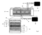
図1〜3では、下部内面14を有する鋳型12を含んで成る組立品10を示す。鋳型12は、その中に配置されるレイアップ構成を収容するのに十分高い側部を有する平らな開放鋳型である。下面14には、第1の導管18へと接続されている第1の開口部16が設けられる。基部レイアップ20は、下部内面14上に構成されており、
メッシュの形態の真空媒体22と、
剥離材料24と、
補強材料26と、
障壁層27と、を含んで成る。
One embodiment of the present invention is described herein by reference only by way of reference to the accompanying drawings.
1 to 3 show an
Peeling
Reinforcing
The
鋳型12に基部レイアップ20が構成されると、その基部レイアップ20に対してセル状構造体28が付与され、そのセル状構造体28の上に搬送液とミクロスフェアとの均質な液体混合物が流される。この混合物は流動可能なため、セル状構造体28のプロファイルにしたがってほぼ均一な厚さに安定するものの、さらにより均等な層を確実にすべくこの混合物をより平らにすることが望ましい可能性がある。搬送液とミクロスフェアとの混合物がセル状構造体28に対して付与されると、真空ポンプ30が導管18に接続されて動作する。真空ポンプ30は、基部レイアップ20と鋳型10の内部下面14の開口部16とを通して過剰な搬送液を吸い上げる。また、これによって複数のミクロスフェアが圧縮され、より密度が高くまとめられたミクロスフェア構成が作られる。真空ポンプ30と真空メッシュ22との組み合わせによって生じさせられる圧力差により、レイアップ構成のエリア全体を通じた搬送液のほぼ均一な除去がもたらされる。過剰な搬送液が除去されると、濡れたミクロスフェアの密にまとめられた自己支持構成が後に残り、ミクロスフェア層の厚さがハニカムの厚さによって画定されるようにハニカムの上から過剰なミクロスフェアが除去される。除去されたミクロスフェアは、次いで収集及び再使用することができる。
When the
過剰な搬送液とミクロスフェアとが除去されると、導管18が封止され、真空ポンプ30が切断され得る/オフにされ得る。続いて、ミクロスフェア28aの上に頂部レイアップ34が付与され、その頂部レイアップ34は、ミクロスフェア28a及びセル状構造体28に隣接する障壁層36と、障壁層36の上の補強材料38と、補強材料38の上面上の剥離材料40と、剥離材料40に隣り合う真空媒体42とを含んで成ることで底部レイアップ20を再現している。頂部鋳型44は浮いたコール板(caul plate)の形態であってよく、頂部レイアップ34の上に付与される。頂部鋳型44は、複合レイアップに対して圧力を付与することができるように、鋳型12の内部の空間に適合する。頂部鋳型44には開口部46が設けられ、それによってレイアップ構成内から頂部鋳型44の外側へ流体連通可能である。鋳型12の内部中空部を気密封止するために、次いで鋳型12の上を覆って真空フィルム48が配置され、そこに固定される。真空フィルム48にも、同様に開口部が設けられる。頂部鋳型44の開口部46と真空フィルム48とに対して、第2の導管52が取り付けられる。
When excess transport fluid and microspheres are removed, the
第2の導管52は、真空ポンプ54に接続され、真空ポンプ54は、ミクロスフェアと搬送液との混合物からより多くの搬送液を除去するために動作する。搬送液の蒸発/沸騰、又はその粘度の減少を促進するために熱も付与され得、第1の導管18が開かれて、搬送液の除去を促進するためにこの組立品を通る空気の流動を可能にすることができる。別の実施形態において、搬送液が注入に使用されるマトリックス材料であるか、又はそれに対応する場合、搬送液の完全な除去は要求されず、蒸発/沸騰工程は必要とされない。障壁層27及び36は、その中に開口部が設けられて空気、搬送液、及び樹脂の通過を可能にするが、それらは、そこを通ってミクロスフェア28aが通過するのを阻止するために十分なほど小さい。
The
搬送液が必要な限り多く除去されると、第1の導管18は樹脂ソース56に接続され、第2の導管52に接続された真空ポンプ54が動作する。樹脂が鋳型12の開口部16を通って組立品へと引き込まれ、基部レイアップ20へと通る。その樹脂は続いてセル状構造体28へと通り、ミクロスフェア層28aを包んだ後に、通過して頂部レイアップ34へと至る。その樹脂が複合レイアップへと侵入するにつれて、組立品内の揮発性物質及び/又は空気が第2の導管52に向かって上がり、第2の導管52へと通る。組立品に完全
に樹脂が注入された時に、次いで硬化され、ミクロスフェアで充填されたセル状コア28に固着された補強スキン26及び38を有する複合サンドイッチ構造体を作ることができる。
When as much transport liquid as necessary is removed, the
図4では、図1〜3において示す処理中のミクロスフェア28aを示すが、簡略化のためにセル状構造体は図示しない。ミクロスフェア28aは、最初は搬送液の溶液中に存在する。次いで、真空ポンプ30及び54の動作中に混合物28から過剰な搬送液28bが除去され、ミクロスフェアがより密にまとめられる。残留搬送液が除去され、セル状構造体内において、効果的に真空60中に存在する密度が高くまとめられたミクロスフェア28aが残される。そのミクロスフェア28aには次いで樹脂58が注入され、セル状コアの所定の位置に固着、すなわち固定される。樹脂58は、複数のミクロスフェア28aの間に侵入し、それらを所定の位置に固着させ、セル状構造体と組み合わせて複合構造体のコアの一部とする。
FIG. 4 shows the
鋳型の下面と頂部鋳型とは好適には剛直であり、それによってサンドイッチ構造体をより正確に成形することが可能になる。しかし、頂部鋳型を使用することは必須ではない。部品全体にマトリックス材料を分配させる、より良い手段を提供するために、鋳型に樹脂流動チャネルなどのさらなる特徴を組み込むことができる。また、鋳型の真空封止は、使い捨てプラスチックフィルムを使用して実行されても、又はシリコーン製のものなど再使用可能な真空バッグによって実行されてもよい。 The bottom and top molds of the mold are preferably rigid, which allows the sandwich structure to be molded more accurately. However, it is not mandatory to use a top mold. Additional features such as resin flow channels can be incorporated into the mold to provide a better means of distributing the matrix material throughout the component. Also, the vacuum encapsulation of the mold may be performed using a disposable plastic film or a reusable vacuum bag such as one made of silicone.
一実施形態では、ミクロスフェアが鋳型12の壁部を必要とすることなくハニカムコア内に収容され得ることから、鋳型12は必要とされない場合がある。
搬送液の使用法に応じて、ミクロスフェアは処理要件にしたがって様々なちょう度を有し得る。例えば、搬送液が使用されずミクロスフェアが乾燥したままの場合、搬送液の除去又は蒸発の必要がなくなる。しかし、これによってミクロスフェアが簡単に空気で運ばれることができるようになり、それらを密な構成にまとめることはより難しく、湾曲部を有する形状を製造する場合にミクロスフェアが浮いてハニカムセルの外に出ることを阻止することができない。搬送液が使用される場合は、これらの問題は克服され得る。ミクロスフェアと搬送液との液体混合物及び続く過剰な搬送液の除去によって、その混合物の素早く簡単な運搬、堆積、及び拡散が可能になる。また、搬送液の凝集力によって、ミクロスフェアは密にまとめられ、一緒に保持される。これに加えて、材料の気密封止に先立ってその材料を通したガスの引き出しを行うために真空ソースを使用することによって、成形に先立ってミクロスフェアがさらに圧縮され、それによって材料内でミクロスフェアのより高い体積分率が得られる。
In one embodiment, the
Depending on the usage of the carrier, the microspheres can have varying consistency according to the treatment requirements. For example, if the transport liquid is not used and the microspheres remain dry, there is no need to remove or evaporate the transport liquid. However, this makes it easier for the microspheres to be carried by air, making it more difficult to put them together in a dense configuration, and the microspheres float when manufacturing shapes with curved parts of the honeycomb cell. You can't prevent them from going out. These problems can be overcome if a carrier is used. Removal of the liquid mixture of microspheres and transfer fluid and subsequent excess transfer fluid allows for quick and easy transport, deposition, and diffusion of the mixture. Also, due to the cohesive force of the transport liquid, the microspheres are tightly packed and held together. In addition to this, by using a vacuum source to draw gas through the material prior to the airtight seal of the material, the microspheres are further compressed prior to molding, thereby the micros in the material. A higher volume fraction of the fair is obtained.
本発明の別の実施形態では、レイアップ構成の全体又は少なくとも一部が、まず別のエリアに用意され、次いで最終的な成形面上に移される。例えば、ハニカムコア内のミクロスフェアのコア層は、図1に開示されるプロセスと類似のプロセス、又は別のプロセスを使用することによって、別に用意されることができる。過剰な搬送液の除去に続いて、セル状コア内の粒子は濡れたままであるものの、密にまとめられる。液体の表面張力は、それらの粒子の間に化学結合が無くとも、それらの粒子をセル状構造体内に共に保持するように作用する。これによって、簡単に鋳型から除去でき、移すことができ、次いでその一体性に影響することなく異なる面/鋳型上に配置されることができる、自己支持性だが形成可能な構造体となる。この新たな面は、マトリックス材料の案内を考慮に入れた導管と、底部補強材料とを備えてよく、用意したコアの配置に先立って、任意で、真空媒体と剥離材料とがこの面上に積まれる。コアの配置の後、頂部材料層が配置され、図3に示すように、本明細書に記載のプロセスにしたがってマトリックス材料が案内及び硬化される。これによって、複雑な形状を有するサンドイッチパネルを製造するための素早く効率的な方法が可能になる。さらに、ミクロスフェアで充填された別のシートのハニカムが、大き
な部品を製造するために互いに隣り合って、又は互いの上に積まれてもよい。コア前駆体材料の複数の別のシートの間に結果として生じる任意の間隙は、続いて乾燥粒子又は搬送液中の粒子のいずれかによって充填され得る。最終的な鋳型中へのコア層の配置に先立ってそれらのコア層を用意するさらなる利益は、それらの用意に、用意プロセスの速度と効率とを改善可能な専用の鋳型を使用することができることである。
In another embodiment of the invention, all or at least a portion of the layup configuration is first prepared in another area and then transferred onto the final molded surface. For example, the core layer of microspheres in the honeycomb core can be prepared separately by using a process similar to or another process similar to the process disclosed in FIG. Following the removal of excess carrier, the particles in the cellular core remain wet but are tightly packed. The surface tension of the liquid acts to hold the particles together in the cellular structure, even if there are no chemical bonds between them. This results in a self-supporting but formable structure that can be easily removed from the mold, transferred, and then placed on different faces / molds without affecting its integrity. This new surface may include a conduit that takes into account the guidance of the matrix material and a bottom reinforcement material, optionally with a vacuum medium and release material on this surface prior to the placement of the prepared core. Stacked. After placement of the core, a top material layer is placed and the matrix material is guided and cured according to the process described herein, as shown in FIG. This allows for a quick and efficient way to manufacture sandwich panels with complex shapes. In addition, honeycombs of different sheets filled with microspheres may be stacked next to each other or on top of each other to produce large parts. Any resulting gap between multiple separate sheets of core precursor material can subsequently be filled with either dry particles or particles in the carrier. A further benefit of preparing those core layers prior to placement of the core layers in the final mold is that dedicated molds that can improve the speed and efficiency of the preparation process can be used for their preparation. Is.
コア前駆体を用意し、続いてそれらの形成、注入、及び硬化を行うこのプロセスは、ラミネート補強を有しないシンタクチックフォームの製造に簡単に適合し得る。
樹脂は、第1の導管に接続された真空ポンプによって第1の導管よりむしろ第2の導管から注入されてよい。これに代えて、又はこれに加えて、搬送液の除去、樹脂の供給、又は真空ソースのために、本組立品にさらなる導管が付与されてもよい。マトリックス材料又は樹脂を組立品の底部から注入する利点は、揮発性物質は自然と組立品の上へと上昇することから、揮発性物質が追い払われて空隙容量が最小化され得ることである。
This process of preparing core precursors, followed by their formation, injection, and curing can be readily adapted to the production of syntactic foam without laminate reinforcement.
The resin may be injected from the second conduit rather than the first conduit by a vacuum pump connected to the first conduit. Alternatively or additionally, additional conduits may be provided to the assembly for removal of carrier, supply of resin, or vacuum source. The advantage of injecting the matrix material or resin from the bottom of the assembly is that the volatiles naturally rise onto the assembly so that the volatiles can be driven away and the void volume can be minimized.
本発明の一態様は、従来の樹脂案内プロセスと比較した場合に極めて短い効果的な流動経路を使用してレイアップに対してマトリックス材料が付与されることである。入口ポート及び/又は出口ポートと、樹脂流動チャネル及び/又は真空メッシュと、頂部及び/又は底部レイアップに沿った剥離生地とを配置することによって、本組立品の側部に配置されているポートと比較してマトリックス材料の流動経路が減少される。従来の成形方法(例えば、樹脂トランスファ成形)とは異なり、樹脂は補強部の長さ及び幅を通ってではなく、その厚さを通って進む。したがって、総圧力変化が約1気圧のみであり得るとしても、より急な圧力勾配がこの方法によって達成され得る。これによって、樹脂の浸透に要求される時間が減少する。これに加えて、進行する距離が樹脂トランスファ成形におけるよりもはるかに短いことから、樹脂の硬化前に補強部全体を通ってその樹脂を進ませるために、より少ない圧力又は力しか必要とされない。流動経路長におけるこのような減少は、そこに対する抵抗の減少によってより素早い浸透となり、これは同様に、要求される真空強度及び/又は真空が付与される必要がある時間を減少させ、それによってその構造体の製造の費用を減少させる。 One aspect of the invention is that the matrix material is applied to the layup using a very short and effective flow path when compared to conventional resin guidance processes. Ports located on the sides of the assembly by arranging inlet and / or outlet ports, resin flow channels and / or vacuum mesh, and stripping fabric along the top and / or bottom layup. The flow path of the matrix material is reduced as compared to. Unlike conventional molding methods (eg, resin transfer molding), the resin proceeds through its thickness, not through the length and width of the stiffener. Therefore, even if the total pressure change can be only about 1 atmosphere, a steeper pressure gradient can be achieved by this method. This reduces the time required for resin penetration. In addition to this, less pressure or force is required to advance the resin through the entire reinforcement before the resin cures, as the distance traveled is much shorter than in resin transfer molding. Such a decrease in flow path length results in faster penetration due to a decrease in resistance to it, which also reduces the required vacuum strength and / or the time that the vacuum needs to be applied, thereby reducing its. Reduce the cost of manufacturing the structure.
補強材料は炭素繊維又は他の材料(ガラス繊維、パラアラミドシンタクチック繊維、他の繊維材料、又はそれらの組み合わせ)の形態であってよい。また、要件によってハニカム材料も多様なものであってよく、アルミニウム、アラミド材料、ガラス繊維、プラスチック、及び他の材料を含み得る。湾曲した部品を成形するためには、鋳型の外形に共形可能である適したコア(例えば、ノーメックス(Nomex)(登録商標)などアラミドベースの材料)を使用することが好適であり得る。ハニカムコアの代わりに使用可能な他の開放セル状構造には、スペーサファブリックか、又はミクロスフェアで充填され、そのミクロスフェアを抑制することができる任意の他の構造体が含まれる。 The reinforcing material may be in the form of carbon fiber or other material (glass fiber, para-aramid syntactic fiber, other fiber material, or a combination thereof). Honeycomb materials may also vary depending on requirements and may include aluminum, aramid materials, fiberglass, plastics, and other materials. For molding curved parts, it may be preferable to use a suitable core that is conformal to the outer shape of the mold (eg, an aramid-based material such as Nomex®). Other open cell structures that can be used in place of the honeycomb core include spacer fabrics or any other structure that is filled with microspheres and can suppress the microspheres.
サンドイッチ構造体の機械特性をさらに調整するために、鋳型の中に、基部レイアップ及び/又は頂部レイアップに対して、又は基部レイアップと頂部レイアップとの間に、インサートが加えられてもよい。これらは、部品の残りと共に注入されることができる中実な構造体(例えば、金属及び予備硬化された複合体)又は多孔質材料(乾燥生地又は多孔質剛体)の形態であってよい。これに加えて、又はこれに代えて、特に強化剤及び/又はミルドファイバ若しくはチョップドファイバの形態でミクロスフェアと共に添加剤が混合されてもよい。例えば、反応で誘導される相分離(RIPS強化)が樹脂の強化に使用され得る。強靭化剤の案内によって樹脂の粘性が増加しすぎる場合、このような添加剤を粉末、粒子、及び/又は繊維の形態で搬送液と混合して、低い粘性を維持する溶液、乳濁液、又は懸濁液を作ることができる。レイアップ構成から搬送液が除去されると、ミクロスフェアコア中に添加剤が残り、次いで樹脂が案内されることができ、それによって、得られる複合物構造体に対して、要求される特性を提供する。 Even if an insert is added into the mold to further adjust the mechanical properties of the sandwich structure, with respect to the base layup and / or the top layup, or between the base layup and the top layup. Good. These may be in the form of solid structures (eg, metals and pre-cured composites) or porous materials (dry dough or porous rigid bodies) that can be injected with the rest of the part. In addition to or instead of this, additives may be mixed with microspheres, especially in the form of reinforcing agents and / or milled or chopped fibers. For example, reaction-induced phase separation (RIPS enhancement) can be used to enhance the resin. If the guidance of the toughening agent increases the viscosity of the resin too much, such additives may be mixed with the carrier in the form of powders, particles, and / or fibers to maintain low viscosity solutions, emulsions, Alternatively, a suspension can be made. When the carrier is removed from the layup configuration, the additive remains in the microsphere core and then the resin can be guided, thereby providing the required properties for the resulting composite structure. provide.
図5では、本発明の一部として用いられ得る組立品を示す。鋳型の基部面14と頂部鋳型44とが、鋳型の側壁12aの周りを挟む。複合サンドイッチ構造体は、鋳型側壁が最終製品と一体となるようにその複合サンドイッチ構造体に結合される側壁を有して作られる。その最終製品は、側壁に結合され、そこから延びる突起部を有する複合サンドイッチ構造体を作るサンドイッチ構造体である。一形態では、複合サンドイッチ構造体は、より確実に鋳型の側壁をサンドイッチ構造体に対して取り付けるべく、その側壁を受け入れる凹部を備えてよい。図5の組立品の結果として、又はその変更として、鋳型又はその一部は、最終製品と一体であることができる。鋳型の面は、最終製品に含まれる材料によって部分的又は完全に覆われており、これによって鋳型に剥離材料を付与する必要がなくなる。これに加えて、各サンドイッチ構造体ごとに新たな鋳型面が要求されることから、鋳型の修理及び維持が不要となる。さらに、樹脂が熱可塑性マトリックス(適したアクリル樹脂など)の前駆体である場合、アクリルフィルム又はアクリルシートは、真空成型されることができ、続いて付与される複合材料と共に鋳型又は別の組立品の所定の位置に保持されることができる。このような組立品は、得られる構造体の離型をより簡単にし、鋳型に剥離部を再び付与する必要性を排除して、ゲルコート及び研磨等の使用を必要とすることなく極めて滑らかな面仕上げを設けることができる。
FIG. 5 shows an assembly that can be used as part of the present invention. The
本明細書に開示されている本発明の一実施形態の態様は、本発明の異なる態様に追加して用いられても、代替として用いられてよい。例えば、一実施形態の方法の一工程は、別の実施形態の一工程に対する追加の工程として使用されても、代替として使用されてもよい。 Aspects of one embodiment of the invention disclosed herein may be used in addition to or as an alternative to different aspects of the invention. For example, one step of the method of one embodiment may be used as an additional step or as an alternative to one step of another embodiment.
Claims (17)
一定の面に基部レイアップを設ける工程であって、前記基部レイアップは第1の補強材料層を含んで成る、基部レイアップを設ける工程と、
前記基部レイアップ上にコア層を設ける工程であって、前記コア層は開放セル状構造体を含んで成り、前記開放セル状構造体は固着していないミクロスフェアによって少なくとも部分的に充填されている、コア層を設ける工程と、
前記コア層の上に頂部レイアップを設ける工程であって、前記頂部レイアップは第2の補強材料層を含んで成る、頂部レイアップを設ける工程と、
前記開放セル状構造体に少なくとも部分的に前記ミクロスフェアが導入された後で、圧力差によって前記コア層中にマトリックス材料を案内することによって、前記マトリックス材料が前記コア層を充填し、前記ミクロスフェアをあるべき位置にて結合する、前記マトリックス材料を案内する工程と、
前記マトリックス材料を硬化する工程と、を備える方法。 In the method for manufacturing a composite sandwich structure,
A step of providing a base layup on a certain surface, wherein the base layup includes a first reinforcing material layer, and a step of providing a base layup.
A step of providing a core layer on the base layup, wherein the core layer comprises an open cell structure, which is at least partially filled with non-fixed microspheres. The process of providing the core layer and
A step of providing a top layup on the core layer, wherein the top layup includes a second reinforcing material layer, and a step of providing a top layup.
After the microspheres have been introduced into the open cell structure at least partially, the matrix material fills the core layer by guiding the matrix material into the core layer by a pressure difference, and the micros. The process of guiding the matrix material, which bonds the fairs in place , and
A method comprising a step of curing the matrix material.
Applications Claiming Priority (3)
| Application Number | Priority Date | Filing Date | Title |
|---|---|---|---|
| GB1510065.4A GB2539228B (en) | 2015-06-10 | 2015-06-10 | A method of making a composite structure |
| GB1510065.4 | 2015-06-10 | ||
| PCT/GB2016/051717 WO2016198883A1 (en) | 2015-06-10 | 2016-06-10 | A method of making a composite structure |
Publications (2)
| Publication Number | Publication Date |
|---|---|
| JP2018518402A JP2018518402A (en) | 2018-07-12 |
| JP6862002B2 true JP6862002B2 (en) | 2021-04-21 |
Family
ID=53785237
Family Applications (1)
| Application Number | Title | Priority Date | Filing Date |
|---|---|---|---|
| JP2018516641A Active JP6862002B2 (en) | 2015-06-10 | 2016-06-10 | Manufacturing method of composite structure |
Country Status (18)
| Country | Link |
|---|---|
| US (1) | US11059244B2 (en) |
| EP (1) | EP3307533B1 (en) |
| JP (1) | JP6862002B2 (en) |
| KR (1) | KR102510311B1 (en) |
| CN (2) | CN107872998A (en) |
| AU (1) | AU2016276134B2 (en) |
| BR (1) | BR112017026442B1 (en) |
| CA (1) | CA3026978C (en) |
| DK (1) | DK3307533T3 (en) |
| ES (1) | ES2929530T3 (en) |
| GB (1) | GB2539228B (en) |
| HR (1) | HRP20221321T1 (en) |
| MX (1) | MX2017015966A (en) |
| PL (1) | PL3307533T3 (en) |
| PT (1) | PT3307533T (en) |
| SG (1) | SG11201811820SA (en) |
| TW (1) | TWI753858B (en) |
| WO (1) | WO2016198883A1 (en) |
Families Citing this family (7)
| Publication number | Priority date | Publication date | Assignee | Title |
|---|---|---|---|---|
| CN108372666B (en) * | 2018-02-26 | 2020-06-23 | 常州市新创智能科技有限公司 | Carbon fiber pultrusion profile embedded with metal plate and manufacturing process |
| WO2020028936A1 (en) * | 2018-08-08 | 2020-02-13 | Fast Build Systems Pty Ltd | Preform, composite structure and panel, and methods of forming same |
| CN109648890B (en) * | 2018-12-25 | 2020-12-29 | 中国航空工业集团公司基础技术研究院 | Preparation method of self-supporting semi-impregnated self-adhesive non-buckling pre-set fabric |
| CN112140589B (en) * | 2019-06-28 | 2023-03-24 | 江苏金风科技有限公司 | Vacuum infusion method and cleaning method |
| DE102020200820A1 (en) | 2020-01-23 | 2021-07-29 | Rolls-Royce Deutschland Ltd & Co Kg | Manufacturing process for a layer composite and engine component |
| CN111186147B (en) * | 2020-02-24 | 2021-10-08 | 江苏亨睿碳纤维科技有限公司 | Forming method for preparing lightweight automobile parts by using continuous fiber mixed chopped fibers |
| CN117246027B (en) * | 2023-11-20 | 2024-01-23 | 江苏晶昱宝环境科技有限公司 | High-density composite sound insulation board lamination assembly equipment |
Family Cites Families (25)
| Publication number | Priority date | Publication date | Assignee | Title |
|---|---|---|---|---|
| GB9111621D0 (en) * | 1991-05-30 | 1991-07-24 | Short Brothers Plc | Noise attenuation panel |
| US5445861A (en) * | 1992-09-04 | 1995-08-29 | The Boeing Company | Lightweight honeycomb panel structure |
| US5455096A (en) * | 1993-09-20 | 1995-10-03 | United Technologies Corporation | Complex composite sandwich structure having a laminate and a foaming ashesive therein and a method for making the same |
| AT401757B (en) * | 1994-04-07 | 1996-11-25 | Greiner & Soehne C A | MULTI-LAYER COMPONENT MADE OF THERMALLY DEFORMABLE PLASTIC FOAM |
| JPH08156150A (en) * | 1994-12-06 | 1996-06-18 | Suzuki Sogyo Co Ltd | Sandwich structure using hollow core material and manufacture of the same |
| US5569508A (en) * | 1995-01-03 | 1996-10-29 | The Boeing Company | Resin transfer molding with honeycomb core and core filler |
| CA2195050A1 (en) * | 1996-01-29 | 1997-07-30 | Mark David Thiede-Smet | Low-weight and water-resistant honeycomb sandwich panels made by resin transfer molding process |
| US6030483A (en) * | 1996-09-10 | 2000-02-29 | Wilson; Graeme Paul | Method of forming laminates using a tessellated core |
| US7563504B2 (en) * | 1998-03-27 | 2009-07-21 | Siemens Energy, Inc. | Utilization of discontinuous fibers for improving properties of high temperature insulation of ceramic matrix composites |
| FR2790526B1 (en) * | 1999-03-04 | 2001-10-12 | Cit Alcatel | SHOCK REDUCING STRUCTURAL ARRANGEMENT |
| JP4013573B2 (en) * | 2002-02-07 | 2007-11-28 | 東レ株式会社 | Sound insulation panel construction method |
| JP4010271B2 (en) * | 2003-04-17 | 2007-11-21 | トヨタ自動車株式会社 | Honeycomb structure for FRP sandwich panel |
| JP2005022171A (en) * | 2003-06-30 | 2005-01-27 | Mitsubishi Heavy Ind Ltd | Core for composite material sandwich panel, composite material sandwich panel and its manufacturing method |
| DE602005027449D1 (en) * | 2004-04-30 | 2011-05-26 | Ngk Insulators Ltd | WAVE STRUCTURE AND MANUFACTURING METHOD THEREFOR |
| US7776392B2 (en) * | 2005-04-15 | 2010-08-17 | Siemens Energy, Inc. | Composite insulation tape with loaded HTC materials |
| US7507461B2 (en) * | 2004-09-01 | 2009-03-24 | Hexcel Corporation | Edge coating for honeycomb used in panels with composite face sheets |
| US7988809B2 (en) * | 2004-09-01 | 2011-08-02 | Hexcel Corporation | Aircraft floor and interior panels using edge coated honeycomb |
| JP2006198866A (en) * | 2005-01-20 | 2006-08-03 | Mitsubishi Rayon Co Ltd | Core material for sandwich structure material and method for producing sandwich structure material |
| JP2008290441A (en) * | 2007-04-25 | 2008-12-04 | Sekisui Chem Co Ltd | Method for producing reinforced plastic sandwich material |
| US8292214B2 (en) * | 2008-01-18 | 2012-10-23 | The Boeing Company | Vibration damping for wing-to-body aircraft fairing |
| GB2470618B (en) * | 2009-09-14 | 2011-08-24 | Alexander Fergusson | An improved method of and apparatus for making a composite material |
| WO2012045653A1 (en) * | 2010-10-08 | 2012-04-12 | Fredy Iseli | Honeycomb composite support part and method for coating it |
| DE112012003075T5 (en) * | 2011-07-22 | 2014-07-31 | Dow Global Technologies Llc | Process for the preparation of cemented and skinned acicular gauze honeycomb structures |
| JP5836730B2 (en) * | 2011-09-26 | 2015-12-24 | 三菱電機株式会社 | Flame retardant composite materials and elevator car components |
| EP2610053B1 (en) * | 2011-12-28 | 2019-06-19 | Siemens Gamesa Renewable Energy A/S | Sandwich Core Material |
-
2015
- 2015-06-10 GB GB1510065.4A patent/GB2539228B/en active Active
-
2016
- 2016-06-10 BR BR112017026442-0A patent/BR112017026442B1/en active IP Right Grant
- 2016-06-10 DK DK16736556.8T patent/DK3307533T3/en active
- 2016-06-10 AU AU2016276134A patent/AU2016276134B2/en active Active
- 2016-06-10 CA CA3026978A patent/CA3026978C/en active Active
- 2016-06-10 SG SG11201811820SA patent/SG11201811820SA/en unknown
- 2016-06-10 PT PT167365568T patent/PT3307533T/en unknown
- 2016-06-10 JP JP2018516641A patent/JP6862002B2/en active Active
- 2016-06-10 US US15/580,739 patent/US11059244B2/en active Active
- 2016-06-10 WO PCT/GB2016/051717 patent/WO2016198883A1/en not_active Ceased
- 2016-06-10 PL PL16736556.8T patent/PL3307533T3/en unknown
- 2016-06-10 CN CN201680033380.6A patent/CN107872998A/en active Pending
- 2016-06-10 MX MX2017015966A patent/MX2017015966A/en unknown
- 2016-06-10 ES ES16736556T patent/ES2929530T3/en active Active
- 2016-06-10 HR HRP20221321TT patent/HRP20221321T1/en unknown
- 2016-06-10 KR KR1020187000840A patent/KR102510311B1/en active Active
- 2016-06-10 CN CN202410243341.5A patent/CN118254395A/en active Pending
- 2016-06-10 EP EP16736556.8A patent/EP3307533B1/en active Active
- 2016-06-13 TW TW105118387A patent/TWI753858B/en active
Also Published As
| Publication number | Publication date |
|---|---|
| PL3307533T3 (en) | 2022-11-28 |
| WO2016198883A1 (en) | 2016-12-15 |
| BR112017026442B1 (en) | 2022-01-18 |
| MX2017015966A (en) | 2018-07-06 |
| AU2016276134A1 (en) | 2018-01-18 |
| KR20180037175A (en) | 2018-04-11 |
| BR112017026442A2 (en) | 2018-08-14 |
| US11059244B2 (en) | 2021-07-13 |
| CN107872998A (en) | 2018-04-03 |
| KR102510311B1 (en) | 2023-03-14 |
| TW201707947A (en) | 2017-03-01 |
| JP2018518402A (en) | 2018-07-12 |
| CA3026978C (en) | 2021-06-01 |
| GB2539228A (en) | 2016-12-14 |
| CA3026978A1 (en) | 2016-12-15 |
| ES2929530T3 (en) | 2022-11-30 |
| GB2539228B (en) | 2017-07-26 |
| PT3307533T (en) | 2022-11-03 |
| EP3307533B1 (en) | 2022-08-03 |
| TWI753858B (en) | 2022-02-01 |
| US20180147799A1 (en) | 2018-05-31 |
| DK3307533T3 (en) | 2022-11-07 |
| HRP20221321T1 (en) | 2022-12-23 |
| CN118254395A (en) | 2024-06-28 |
| GB201510065D0 (en) | 2015-07-22 |
| AU2016276134B2 (en) | 2020-10-22 |
| EP3307533A1 (en) | 2018-04-18 |
| SG11201811820SA (en) | 2019-01-30 |
Similar Documents
| Publication | Publication Date | Title |
|---|---|---|
| JP6862002B2 (en) | Manufacturing method of composite structure | |
| CN102481731B (en) | Method of producing advanced composite components | |
| CN102695598B (en) | Method for preparing composite materials | |
| US8034268B2 (en) | Method for manufacturing lightweight composite fairing bar | |
| CN102510800A (en) | Method and apparatus for manufacturing composite materials | |
| JP5044220B2 (en) | Carbon foam composite tool and method for using the carbon foam composite tool | |
| CN103958142B (en) | Method for producing preform and method for producing fiber-reinforced plastic molding | |
| CN114030268A (en) | Preparation method of honeycomb sandwich structure composite material with high-strength adhesive bonding performance | |
| JP6025841B2 (en) | Masterless layup mandrel tool | |
| EP4395987A1 (en) | Film-bonded infusion | |
| WO2008137952A2 (en) | Microparticle breather layer for use in composite part manufacture | |
| CN1933952B (en) | Carbon foam composite tooling and methods for using the same | |
| Ma et al. | Laminating Processes of Thermoset Sandwich Composites | |
| JP2007176163A (en) | Manufacturing process of fiber-reinforced plastic | |
| RU2317210C1 (en) | Method of production of the multilayered panel | |
| CN120941773A (en) | A five-dimensional honeycomb sandwich lightweight structural composite material and its preparation method | |
| MX2008004426A (en) | A method for producing a fibre-reinforced product |
Legal Events
| Date | Code | Title | Description |
|---|---|---|---|
| A621 | Written request for application examination |
Free format text: JAPANESE INTERMEDIATE CODE: A621 Effective date: 20190527 |
|
| A977 | Report on retrieval |
Free format text: JAPANESE INTERMEDIATE CODE: A971007 Effective date: 20200318 |
|
| A131 | Notification of reasons for refusal |
Free format text: JAPANESE INTERMEDIATE CODE: A131 Effective date: 20200401 |
|
| A601 | Written request for extension of time |
Free format text: JAPANESE INTERMEDIATE CODE: A601 Effective date: 20200630 |
|
| A521 | Request for written amendment filed |
Free format text: JAPANESE INTERMEDIATE CODE: A523 Effective date: 20200930 |
|
| TRDD | Decision of grant or rejection written | ||
| A01 | Written decision to grant a patent or to grant a registration (utility model) |
Free format text: JAPANESE INTERMEDIATE CODE: A01 Effective date: 20210302 |
|
| A61 | First payment of annual fees (during grant procedure) |
Free format text: JAPANESE INTERMEDIATE CODE: A61 Effective date: 20210324 |
|
| R150 | Certificate of patent or registration of utility model |
Ref document number: 6862002 Country of ref document: JP Free format text: JAPANESE INTERMEDIATE CODE: R150 |
|
| R250 | Receipt of annual fees |
Free format text: JAPANESE INTERMEDIATE CODE: R250 |