JP6861491B2 - Seat truck - Google Patents
Seat truck Download PDFInfo
- Publication number
- JP6861491B2 JP6861491B2 JP2016181663A JP2016181663A JP6861491B2 JP 6861491 B2 JP6861491 B2 JP 6861491B2 JP 2016181663 A JP2016181663 A JP 2016181663A JP 2016181663 A JP2016181663 A JP 2016181663A JP 6861491 B2 JP6861491 B2 JP 6861491B2
- Authority
- JP
- Japan
- Prior art keywords
- rail
- sliding direction
- retainer
- relative sliding
- steel balls
- Prior art date
- Legal status (The legal status is an assumption and is not a legal conclusion. Google has not performed a legal analysis and makes no representation as to the accuracy of the status listed.)
- Active
Links
Images

Classifications
-
- B—PERFORMING OPERATIONS; TRANSPORTING
- B60—VEHICLES IN GENERAL
- B60N—SEATS SPECIALLY ADAPTED FOR VEHICLES; VEHICLE PASSENGER ACCOMMODATION NOT OTHERWISE PROVIDED FOR
- B60N2/00—Seats specially adapted for vehicles; Arrangement or mounting of seats in vehicles
- B60N2/02—Seats specially adapted for vehicles; Arrangement or mounting of seats in vehicles the seat or part thereof being movable, e.g. adjustable
- B60N2/04—Seats specially adapted for vehicles; Arrangement or mounting of seats in vehicles the seat or part thereof being movable, e.g. adjustable the whole seat being movable
- B60N2/06—Seats specially adapted for vehicles; Arrangement or mounting of seats in vehicles the seat or part thereof being movable, e.g. adjustable the whole seat being movable slidable
- B60N2/08—Seats specially adapted for vehicles; Arrangement or mounting of seats in vehicles the seat or part thereof being movable, e.g. adjustable the whole seat being movable slidable characterised by the locking device
- B60N2/0806—Seats specially adapted for vehicles; Arrangement or mounting of seats in vehicles the seat or part thereof being movable, e.g. adjustable the whole seat being movable slidable characterised by the locking device with pin alignment systems, e.g. with at least one of a plurality of locking pins always aligned w.r.t. at least one of a plurality of pin-receiving elements
-
- B—PERFORMING OPERATIONS; TRANSPORTING
- B60—VEHICLES IN GENERAL
- B60N—SEATS SPECIALLY ADAPTED FOR VEHICLES; VEHICLE PASSENGER ACCOMMODATION NOT OTHERWISE PROVIDED FOR
- B60N2/00—Seats specially adapted for vehicles; Arrangement or mounting of seats in vehicles
- B60N2/02—Seats specially adapted for vehicles; Arrangement or mounting of seats in vehicles the seat or part thereof being movable, e.g. adjustable
- B60N2/04—Seats specially adapted for vehicles; Arrangement or mounting of seats in vehicles the seat or part thereof being movable, e.g. adjustable the whole seat being movable
- B60N2/06—Seats specially adapted for vehicles; Arrangement or mounting of seats in vehicles the seat or part thereof being movable, e.g. adjustable the whole seat being movable slidable
- B60N2/07—Slide construction
- B60N2/0702—Slide construction characterised by its cross-section
- B60N2/0705—Slide construction characterised by its cross-section omega-shaped
-
- B—PERFORMING OPERATIONS; TRANSPORTING
- B60—VEHICLES IN GENERAL
- B60N—SEATS SPECIALLY ADAPTED FOR VEHICLES; VEHICLE PASSENGER ACCOMMODATION NOT OTHERWISE PROVIDED FOR
- B60N2/00—Seats specially adapted for vehicles; Arrangement or mounting of seats in vehicles
- B60N2/02—Seats specially adapted for vehicles; Arrangement or mounting of seats in vehicles the seat or part thereof being movable, e.g. adjustable
- B60N2/04—Seats specially adapted for vehicles; Arrangement or mounting of seats in vehicles the seat or part thereof being movable, e.g. adjustable the whole seat being movable
- B60N2/06—Seats specially adapted for vehicles; Arrangement or mounting of seats in vehicles the seat or part thereof being movable, e.g. adjustable the whole seat being movable slidable
- B60N2/07—Slide construction
- B60N2/0702—Slide construction characterised by its cross-section
- B60N2/0715—C or U-shaped
-
- B—PERFORMING OPERATIONS; TRANSPORTING
- B60—VEHICLES IN GENERAL
- B60N—SEATS SPECIALLY ADAPTED FOR VEHICLES; VEHICLE PASSENGER ACCOMMODATION NOT OTHERWISE PROVIDED FOR
- B60N2/00—Seats specially adapted for vehicles; Arrangement or mounting of seats in vehicles
- B60N2/02—Seats specially adapted for vehicles; Arrangement or mounting of seats in vehicles the seat or part thereof being movable, e.g. adjustable
- B60N2/04—Seats specially adapted for vehicles; Arrangement or mounting of seats in vehicles the seat or part thereof being movable, e.g. adjustable the whole seat being movable
- B60N2/06—Seats specially adapted for vehicles; Arrangement or mounting of seats in vehicles the seat or part thereof being movable, e.g. adjustable the whole seat being movable slidable
- B60N2/07—Slide construction
- B60N2/0722—Constructive details
- B60N2/0727—Stop members for limiting sliding movement
-
- B—PERFORMING OPERATIONS; TRANSPORTING
- B60—VEHICLES IN GENERAL
- B60N—SEATS SPECIALLY ADAPTED FOR VEHICLES; VEHICLE PASSENGER ACCOMMODATION NOT OTHERWISE PROVIDED FOR
- B60N2/00—Seats specially adapted for vehicles; Arrangement or mounting of seats in vehicles
- B60N2/02—Seats specially adapted for vehicles; Arrangement or mounting of seats in vehicles the seat or part thereof being movable, e.g. adjustable
- B60N2/04—Seats specially adapted for vehicles; Arrangement or mounting of seats in vehicles the seat or part thereof being movable, e.g. adjustable the whole seat being movable
- B60N2/06—Seats specially adapted for vehicles; Arrangement or mounting of seats in vehicles the seat or part thereof being movable, e.g. adjustable the whole seat being movable slidable
- B60N2/08—Seats specially adapted for vehicles; Arrangement or mounting of seats in vehicles the seat or part thereof being movable, e.g. adjustable the whole seat being movable slidable characterised by the locking device
- B60N2/0812—Location of the latch
- B60N2/0818—Location of the latch inside the rail
-
- B—PERFORMING OPERATIONS; TRANSPORTING
- B60—VEHICLES IN GENERAL
- B60N—SEATS SPECIALLY ADAPTED FOR VEHICLES; VEHICLE PASSENGER ACCOMMODATION NOT OTHERWISE PROVIDED FOR
- B60N2/00—Seats specially adapted for vehicles; Arrangement or mounting of seats in vehicles
- B60N2/02—Seats specially adapted for vehicles; Arrangement or mounting of seats in vehicles the seat or part thereof being movable, e.g. adjustable
- B60N2/04—Seats specially adapted for vehicles; Arrangement or mounting of seats in vehicles the seat or part thereof being movable, e.g. adjustable the whole seat being movable
- B60N2/06—Seats specially adapted for vehicles; Arrangement or mounting of seats in vehicles the seat or part thereof being movable, e.g. adjustable the whole seat being movable slidable
- B60N2/08—Seats specially adapted for vehicles; Arrangement or mounting of seats in vehicles the seat or part thereof being movable, e.g. adjustable the whole seat being movable slidable characterised by the locking device
- B60N2/0831—Movement of the latch
- B60N2/0837—Movement of the latch pivoting
- B60N2/0843—Movement of the latch pivoting about a longitudinal axis
Landscapes
- Engineering & Computer Science (AREA)
- Aviation & Aerospace Engineering (AREA)
- Transportation (AREA)
- Mechanical Engineering (AREA)
- Seats For Vehicles (AREA)
Description
本発明は、ロアレール,該ロアレールにスライド可能に係合するアッパレールからなるシートレールを有するシートトラックに関する。 The present invention relates to a seat track having a lower rail and a seat rail including an upper rail that is slidably engaged with the lower rail.
図8を用いて従来のシートトラックを説明する。図8は従来のシートトラックの主要部を示す斜視図である。
シートトラック1は、フロア側に設けられたロアレール3と、ロアレール3にスライド可能に係合するアッパレール5を有している。
A conventional seat truck will be described with reference to FIG. FIG. 8 is a perspective view showing a main part of a conventional seat truck.
The seat truck 1 has a
ロアレール3とアッパレール5との間には、ロアレール3に対してアッパレール5を矢印A方向に移動可能に支持する鋼球が設けられている。
本従来例の鋼球は、アッパ鋼球7と、アッパレール5のスライド方向に沿って配置され、アッパ鋼球7より下側に位置する2つのロア鋼球9とからなっている。これらのアッパ鋼球7、ロア鋼球9は、リテーナ11により保持されている。
A steel ball is provided between the
The steel ball of the present conventional example is composed of an upper steel ball 7 and two
ロアレール3には、リテーナ11が当接可能で、リテーナ(アッパ鋼球7,ロア鋼球9)の移動範囲を規制するストッパ13が形成されている。
ストッパ13は、穴13aと、穴13aの下縁部から折曲され、アッパレール5のスライド方向と交差する方向に突出し、リテーナ11の移動を規制可能なストッパ本体13bとからなっている。
A
The
次に、上記構成のシートトラックの組付けを説明する。
組付ける前では、ストッパ13のストッパ本体13bは、穴13aの下縁部から折曲されていない。
最初に、開放面となったロアレール3の端面からアッパレール5を挿入する。
Next, the assembly of the seat track having the above configuration will be described.
Before assembling, the
First, the
次に、ロアレール3とアッパレール5との間に、アッパ鋼球7,ロア鋼球9がセットされたリテーナ11を圧入する。
リテーナ11を所定の位置まで圧入した後、ストッパ本体13bを折曲し、ストッパ13として機能させる(例えば、特許文献1参照)。
Next, the
After the
しかし、図8に示す構成のシートスライドでは、組付け時、ロアレール3とアッパレール5との間に、リテーナ11を圧入する際に、ストッパ13の穴13aに、アッパ鋼球7が落ち込む場合がある。
近年、シートスライドの小型化の要望があり、鋼球、特に、アッパ鋼球7の径を小さくして、シートスライドの断面形状を小さくすることが提案されている。
However, in the seat slide having the configuration shown in FIG. 8, the upper steel ball 7 may fall into the
In recent years, there has been a demand for miniaturization of the seat slide, and it has been proposed to reduce the diameter of the steel ball, particularly the upper steel ball 7, to reduce the cross-sectional shape of the seat slide.
アッパ鋼球7の径が大きい場合では、ストッパ13の穴13aに、アッパ鋼球7が2個とも落ち込んでも、その落ち込み量は少なく(引っ掛かる程度)組立者がリテーナ11を押し込むことで、アッパ鋼球7はストッパ13の穴13aを乗り越えていた。
しかし、アッパ鋼球7の径を小さくした場合、アッパ鋼球7の穴13aへの落ち込み量が大きくなり、組立者の力ではリテーナ11を押し込めなくなっている。
When the diameter of the upper steel ball 7 is large, even if both of the upper steel balls 7 fall into the
However, when the diameter of the upper steel ball 7 is reduced, the amount of the upper steel ball 7 falling into the
本発明は、上記問題点に鑑みてなされたもので、その課題は、鋼球のストッパの穴への過度な落ち込みを防止できるシートスライドを提供することにある。 The present invention has been made in view of the above problems, and an object of the present invention is to provide a seat slide capable of preventing an excessive drop of a steel ball into a stopper hole.
上述した課題のうち少なくとも一つを実現するために、本発明の一側面を反映したシートトラックは、フロア、シートのいずれか一方の側に設けられた第1レールと、前記フロア、前記シートのいずれか他方の側に設けられ、前記第1レールに係合し、前記第1レールに対して相対スライド方向に移動可能な第2レールと、前記第1レールと前記第2レールとの間に少なくとも2つ配置され、前記第1レールに対して前記第2レールを前記相対スライド方向に移動可能に支持する鋼球と、前記第1レールと前記第2レールとの間に設けられ、少なくとも2つの前記鋼球を前記相対スライド方向に沿った離間状態で保持するリテーナと、前記フロア側のレールに設けられ、前記リテーナの前記相対スライド方向への移動を規制可能なストッパと、を有し、前記ストッパは、前記フロア側のレールに形成されるとともに、前記相対スライド方向に離間した一対の内壁を有する穴と、前記穴の縁部から前記相対スライド方向と交差する方向に突出し、前記リテーナと当接することで、前記リテーナの前記相対スライド方向への移動を規制するストッパ本体と、からなり、前記リテーナに保持された少なくとも2つの前記鋼球のうち、前記相対スライド方向における両端に配置された2つの前記鋼球の中心間の距離をL1、前記相対スライド方向における前記穴の前記一対の内壁間の距離をL2、とした場合、L1≧L2であることを特徴とする。
また、本発明の一側面を反映したシートトラックは、前記リテーナは、前記相対スライド方向の両端に位置する一対の外壁を有しており、前記ストッパ本体は、前記相対スライド方向において、前記穴の前記一対の内壁の間に位置しており、且つ、前記穴の前記一対の内壁に対向する一対の外壁を有しており、前記相対スライド方向における前記穴の内壁とこの内壁と対向する前記ストッパ本体の外壁との距離をL3、前記相対スライド方向における前記リテーナの外壁とこの外壁に近接する鋼球の中心との距離をL4、とした場合、L3<L4であることを特徴とする。
さらに、本発明の一側面を反映したシートトラックは、前記リテーナは、前記相対スライド方向に沿って離間状態で配置された前記鋼球としての2つのアッパ鋼球と、前記相対スライド方向に沿って離間状態で配置され、アッパ鋼球より下側に位置する2つのロア鋼球と、を保持し、前記2つのアッパ鋼球の中心間の距離をL1、前記2つのロア鋼球の中心間の距離をL5、とした場合、L1>L5であることを特徴とする。
In order to realize at least one of the above-mentioned problems, the seat track reflecting one aspect of the present invention includes a first rail provided on either side of the floor or the seat, and the floor and the seat. Between a second rail provided on either other side, engaged with the first rail, and movable in a sliding direction relative to the first rail, and between the first rail and the second rail. At least two are arranged , and at least two are provided between the first rail and the second rail, and a steel ball that movably supports the second rail with respect to the first rail in the relative sliding direction. It has a retainer that holds the steel balls in a separated state along the relative sliding direction, and a stopper that is provided on the rail on the floor side and can regulate the movement of the retainer in the relative sliding direction. the stopper is Rutotomoni formed in the floor of the rail, and a hole having a pair of inner walls spaced on the relative sliding direction, protrude in a direction crossing the front Symbol relative sliding direction from the edge of the hole, the It consists of a stopper body that regulates the movement of the retainer in the relative slide direction by abutting with the retainer, and is arranged at both ends of at least two steel balls held by the retainer in the relative slide direction. when the distance between the centers of two of the steel ball which is L1, the distance between the pair of inner wall of the bore before Symbol Relative sliding direction L2, and characterized in that it is a L1 ≧ L2.
Further, in the seat track reflecting one aspect of the present invention, the retainer has a pair of outer walls located at both ends in the relative slide direction, and the stopper body has the hole in the relative slide direction. A stopper located between the pair of inner walls and having a pair of outer walls facing the pair of inner walls of the hole, the inner wall of the hole in the relative sliding direction and the stopper facing the inner wall. When the distance from the outer wall of the main body is L3 and the distance between the outer wall of the retainer and the center of the steel ball close to the outer wall in the relative sliding direction is L4, L3 <L4.
Further, in the seat track reflecting one aspect of the present invention, the retainer has two upper steel balls as the steel balls arranged in a separated state along the relative sliding direction and the same along the relative sliding direction. Two lower steel balls arranged in a separated state and located below the upper steel ball are held, the distance between the centers of the two upper steel balls is L1, and the distance between the centers of the two lower steel balls is L1. When the distance is L5, it is characterized in that L1> L5.
本発明の他の特徴は、以下に述べる発明を実施するための形態並びに添付の図面から一層明らかになるであろう。 Other features of the invention will become more apparent from the embodiments and accompanying drawings for carrying out the invention described below.
本発明のシートトラックによれば、前記第2レールの相対スライド方向における両端に配置された2つの前記鋼球の中心間の距離をL1、前記第2レールの相対スライド方向における前記穴の内壁間の距離をL2、とした場合、L1≧L2であることにより、全ての鋼球がストッパの穴に同時に落ち込むことがなくなる。よって、鋼球のストッパの穴への過度な落ち込みを防止できる。 According to the seat track of the present invention, the distance between the centers of the two steel balls arranged at both ends in the relative sliding direction of the second rail is L1, and the distance between the inner walls of the holes in the relative sliding direction of the second rail is L1. When the distance is L2, since L1 ≧ L2, all the steel balls do not fall into the holes of the stopper at the same time. Therefore, it is possible to prevent an excessive drop into the hole of the stopper of the steel ball.
本発明の他の効果は、以下に述べる発明を実施するための形態並びに添付の図面から一層明らかになるであろう。 Other effects of the present invention will become even more apparent from the embodiments and accompanying drawings for carrying out the invention described below.
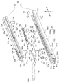
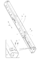
(全体構成)
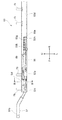
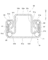
図1−図3を用いて、本実施形態のシートトラックの全体構成を説明する。図1は本実施形態のシートトラックを上から見た時の分解斜視図、図2は図1のシートトラックを組み立てた際の図1の矢印IIから見たアッパレールの正面図、図3は図2の切断線III−IIIでの切断部端面図である。
(overall structure)
The overall configuration of the seat truck of the present embodiment will be described with reference to FIGS. 1 to 3. FIG. 1 is an exploded perspective view of the seat truck of the present embodiment when viewed from above, FIG. 2 is a front view of the upper rail as viewed from arrow II of FIG. 1 when the seat truck of FIG. 1 is assembled, and FIG. 3 is a view. 2 is an end view of the cut portion at the cutting line III-III.
シートレール50は、フロア側に設けられるロアレール51と、シート側に設けられ、このロアレール51にスライド可能に係合したアッパレール53とからなっている。
アッパレール53には、ロアレール51に対するアッパレール53のスライド動作を規制するロック位置、ロアレール51に対するアッパレール53のスライド動作を許容するアンロック位置、アンロック位置よりさらに作動させたフルオープン位置を移動可能なロックレバー55が設けられている(ロック位置、アンロック位置、フルオープン位置は後述する)。
The
The
このロックレバー55は、操作部材57により、ロック位置/アンロック位置/フルオープン位置に切り替えられる。
また、アッパレール53には、アッパレール53のスライド方向を長手とする針金状で、ロックレバー55をロック位置方向に付勢する付勢部材59が設けられている。
The
Further, the
そして、本実施形態では、シートレール50において、操作部材57がある方が前である。
尚、図1−図3及び後述する図5−図7において、矢印F方向が前方向、矢印R方向が後方向、矢印U方向が上方向、矢印L方向が下方向を示している。
(ロアレールとアッパレール)
ロアレール51とアッパレール51を図1−図3を用いて説明する。
Then, in the present embodiment, the
In FIGS. 1 to 3 and 5 to 7 described later, the arrow F direction indicates the forward direction, the arrow R direction indicates the rear direction, the arrow U direction indicates the upward direction, and the arrow L direction indicates the downward direction.
(Lower rail and upper rail)
The
図2、図3に示すように、ロアレール51の断面形状は、フロアと略水平に配置される基底部51aと、基底部51aの一方の端部から折曲され、上方に延出する第1側壁部51bと、基底部51aの他方の端部から折曲され、上方に延出する第2側壁部51cと、第1側壁部51bの上方の端部から折曲し、基底部51aと略平行に第2側壁部51c方向へ延出する第1上面部51dと、第2側壁部51cの上方の端部から折曲し、基底部51aと略平行に第1側壁部51b方向へ延出する第2上面部51eと、第1上面部51dの他方の端部から基底部51a方向に折曲し、第1側壁部51bより長さが短い第1垂下部51fと、第2上面部51eの他方の端部から基底部51a方向に折曲し、第1垂下部51fと空間を介して対向し、第1垂下部51fと略同じ長さの第2垂下部51gとからなっている。
As shown in FIGS. 2 and 3, the cross-sectional shape of the
アッパレール53は、ロアレール51の基底部51aと略平行に設けられた上面部53aと、上面部53aの一方の端部より折曲し、ロアレール51の第1垂下部51fと第2垂下部51gとの間の空間を介してロアレール51内へ延出する第1側壁部53bと、上面部53aの他方の端部より折曲し、ロアレール51の第1垂下部51fと第2垂下部51gとの間の空間を介してロアレール51内へ延出する第2側壁部53cと、第1側壁部53bの下方の端部よりロアレール51の第1側壁部51b、第1上面部51d,第1垂下部51fで形成される空間へ延出する第1跳上部53dと、第2側壁部53cの下方の端部よりロアレール51の第2側壁部51c,第2上面部51e,第2垂下部51gで形成される空間へ延出する第2跳上部53eとからなっている。
The
ここで、ロアレール51の第1側壁部51b、第1上面部51d、第1垂下部51fと、第2側壁部51c、第2上面部51e、第2垂下部51gとは、基底部51aの両側から延出する一対のロアフランジ部として機能する。
また、アッパレール53の第1側壁部53b、第2側壁部53cは、前記一対のロアフランジ部の間に設けられた基部として機能し、第1跳上部53d、第2跳上部53eは、前記基部から延出し、ロアフランジと係合可能な一対のアッパフランジとして機能する。
Here, the first
Further, the first
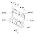
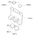
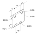
そして、図1、図3、図5−図7を用いて、リテーナの説明を行う。図5はリテーナの斜視図、図6は図5の分解斜視図、図7は図5の斜視図を別の方向から見た斜視図である。
これらの図に示すように、ロアレール51の第1側壁部51bとアッパレール53の第1跳上部53dとの間にリテーナ61が、ロアレール51の第2側壁部51cとアッパレール53の第2跳上部53eとの間にリテーナ67が、アッパレール53のスライド方向に沿ってそれぞれ2つずつ(前方、後方)配置されている。
Then, the retainer will be described with reference to FIGS. 1, 3, and 5 to 7. 5 is a perspective view of the retainer, FIG. 6 is an exploded perspective view of FIG. 5, and FIG. 7 is a perspective view of the perspective view of FIG. 5 as viewed from another direction.
As shown in these figures, a
そして、各リテーナ61に保持された2つの第1アッパ鋼球63が、ロアレール51の第1側壁部51b、第1上面部51dと、アッパレール53の第1跳上部53dとで囲まれた空間に配置されている。各リテーナ61に保持された2つの第1ロア鋼球65がロアレール51の基底部51a、第1側壁部51bと、アッパレール53の第1跳上部53dとで囲まれた 空間に配置されている。
Then, the two first
また、各リテーナ67に保持された2つの第2アッパ鋼球69が、ロアレール51の第2側壁部51c、第2上面部51eと、アッパレール53の第2跳上部53eとで囲まれた空間に配置されている。各リテーナ67に保持された2つの第2ロア鋼球71がロアレール51の基底部51a、第2側壁部51cと、アッパレール53の第2跳上部53eとで囲まれた空間に配置されている。これにより、アッパレール53はロアレール51に対してスムーズにスライド移動する。
Further, the two second
本実施形態では、第1アッパ鋼球63と第2アッパ鋼球69の径寸法、第1ロア鋼球65と第2ロア鋼球71の径寸法は同じとした。
また、2つのリテーナ61の形状と2つのリテーナ67の形状も同一とした。
さらに、図6、図15に示すように、第1アッパ鋼球63と第2アッパ鋼球69の径寸法をΦU、第1ロア鋼球65と第2ロア鋼球71の径寸法をΦLとすると、
ΦU<ΦL
とした。
In the present embodiment, the diameter dimensions of the first
Further, the shapes of the two
Further, as shown in FIGS. 6 and 15, the diameter dimensions of the first
ΦU <ΦL
And said.
また、図1(,図2)に示すように、ロアレール51には、リテーナ61、リテーナ67が当接することにより、鋼球(第1アッパ鋼球63、第2アッパ鋼球69、第1ロア鋼球65、第2ロア鋼球71)の移動範囲を規制するストッパが設けられている。
本実施形態のストッパは、ロアレール51の第1側壁部51b、第2側壁部51cの上部で両端の開放面側に設けられたアッパストッパ101と、ロアレール51の第1側壁部51b、第2側壁部51cの下部で長手方向の中間部に設けられたロアストッパ103とからなっている。
Further, as shown in FIG. 1 (, FIG. 2), the
The stoppers of the present embodiment include an
ストッパ101は、第1アッパ鋼球63、第2アッパ鋼球69がアッパレール53のスライド方向に通過可能な穴101aと、穴101aの下縁部からアッパレール53のスライド方向と交差する方向に突出し、リテーナ61、リテーナ67が当接可能なストッパ本体101bとからなっている。
The
ストッパ103は、穴103aと、穴103aの上縁部からアッパレール53のスライド方向と交差する方向に突出し、リテーナ61、リテーナ67が当接可能なストッパ本体103bとからなっている。
そして、本実施形態では、以下のような寸法関係とした。
The
Then, in the present embodiment, the following dimensional relationship is adopted.
(1) 図5,図7に示すように、リテーナ61、67に保持された2つのアッパ鋼球63、69の中心間の距離をL1、
図1に示すように、アッパレール53のスライド方向におけるストッパ101の穴101aの内壁間の距離をL2、
とした場合、
L1≧L2
(2) 図1に示すように、アッパレール53のスライド方向におけるストッパ101の穴101aの内壁とこの内壁101aと対向するストッパ本体101bの外壁との距離をL3,
図5、図7に示すように、アッパレール53のスライド方向における第1アッパ鋼球63、69の中心と、リテーナ61、67の外壁との距離をL4、
とした場合、
L3<L4
である
(3) リテーナ61、67に保持された2つの第1ロア鋼球65、第2ロア鋼球71の中心間の距離をL5、
とした場合、
L1>L5
図1に示すように、ロアレール51の基底部51aを挿通するピン73により、ロアレール51はフロア側に取り付けられる。
(1) As shown in FIGS. 5 and 7, the distance between the centers of the two
As shown in FIG. 1, the distance between the inner walls of the
If
L1 ≧ L2
(2) As shown in FIG. 1, the distance between the inner wall of the
As shown in FIGS. 5 and 7, the distance between the center of the first
If
L3 <L4
Is
(3) The distance between the centers of the two first
If
L1> L5
As shown in FIG. 1, the
アッパレール53の上面部53aは、4カ所の孔53fを有し、これらの孔53fを挿通するピン75により、アッパレール53はシート側に取り付けられる。
(ロック機構)
図1−図4を用いて説明する。図4はシートトラックを組み付けた際のアッパレールの斜視図である。
The
(Lock mechanism)
This will be described with reference to FIGS. 1 to 4. FIG. 4 is a perspective view of the upper rail when the seat truck is assembled.
図1、図2、図4に示すように、アッパレール53の上面部53a、第1側壁部53b、第2側壁部53cに囲まれた空間内には、シートトラックの前側より順に、操作部材57の後部と、ロックレバー55とが配置され、さらに、その空間には、操作部材57とロックレバー55とに係止される付勢部材59も配置される。
As shown in FIGS. 1, 2, and 4, in the space surrounded by the
図1に示すように、ロアレール51の第2垂下部51gは、アッパレール53のスライド方向(長手方向)に沿って複数のロック孔(ロアレール51のロック部)51iを有している。尚、本実施形態では、図示しないが、第1垂下部51fも、第2垂下部51gの複数のロック孔51iに対向するロック孔51i(図示せず)を有している。
As shown in FIG. 1, the
また、アッパレール53は、その第1側壁部53bの長手方向中央部に、第1切り欠き部53gを有している。さらに、アッパレール53は、その第1跳上部53dに、切り欠き部53gに対向する第2切り欠き部53hを有している。
図4に示すように、アッパレール53は、その第1側壁部53bに、前方より第1係止孔53i、第2係止孔53jを有している。
Further, the
As shown in FIG. 4, the
一方、図1、図4に示すように、ロックレバー55は、第1係止孔53i、第2係止孔53jに嵌まる突状の第1係止部55i、突状の第2係止部55jを有し、第1係止孔53i、第2係止孔53jを回転支点として(アッパレール53のスライド方向を軸として)、ロック位置−アンロック位置−フルオープン位置との間を回転移動する。
On the other hand, as shown in FIGS. 1 and 4, the
図1、図2に示すように、ロックレバー55の後部には、ロックレバー55が回転することにより、アッパレール53の第1切り欠き部53gを挿通し、ロアレール51の第1垂下部51fのロック孔51iに係脱可能な複数の(本実施形態では6つ)ロック爪(係止部)55aが形成されている。尚、本実施形態では、ロアレール51の第1垂下部51fのロック孔51iに係合したロックレバー55のロック爪55aの先端側は、アッパレール53の第2切り欠き部53hを挿通するようになっている。
As shown in FIGS. 1 and 2, the
そして、アッパレール53に設けられたロックレバー55のロック爪55aが、ロアレール51のロック孔51iに係合することにより、アッパレール53のロアレール51に対するスライド動作が規制される。
(操作部材、付勢部材)
図1、図2、図4を用いて説明する。
Then, the
(Operating member, urging member)
This will be described with reference to FIGS. 1, 2, and 4.
操作部材57は、ロックレバー55より前側に配置される。操作部材57の後部には、ロックレバー55の前部に設けられた円筒面を有した被押圧部55cを上方から押圧可能な押圧部57aが形成されている。操作部材57の前部は、折曲され、シートクッションの前部に沿う操作部57bとなっている。
The operating
また、操作部材57の中間部の上面は、アッパレール53の上面部53aの内壁側に形成された支点突部53lに当接し、当接点を回転支点として上下方向に回転可能となっている。さらに、アッパレール53の第2側壁部53cであって、支点突部53lよりも後方の位置には、操作部材57の下面が当接可能なストッパ突部53mが形成されている。
Further, the upper surface of the intermediate portion of the operating
付勢部材59は、線状の材料(ワイヤー材)を様々な方向に曲げ加工して得られた線細工ばねである。
付勢部材59は、アッパレール53の上面部53aと、一対の側壁部(第1側壁部53b、第2側壁部53c)とで囲まれる空間に、アッパレール53のスライド方向に沿って配置されている。
The urging
The urging
そして、付勢部材59は、その中間部に、アッパレール53に係止される交差部59cを有している。この交差部59cとアッパレール53の係止により、付勢部材59とアッパレール53とのアッパレール53のスライド方向の相対スライドが禁止される。
付勢部材59は、その後部に、アッパレール53のスライド方向と交差する方向に折曲され、ロックレバー55の中間部に形成された孔55bに係止することで、ロックレバー55をロック位置方向に付勢する後部折曲部(アーム部)59aを有している。この後部折曲部59aは、後部折曲部59aがねじられた際の弾性復元力を用いてロックレバー55をロック位置方向に付勢する付勢部として機能する。
The urging
The urging
次に、付勢部材59は、その前端側に、アッパレール53のスライド方向と交差する方向に折曲され、操作部材57の回転支点より前方の下部にアッパレールのスライド方向と交差する方向に形成された溝57cに係止することで、操作部材57のアッパレール53のスライド方向の移動を規制すると共に操作部材57を付勢する規制部(嵌合部)59bを有している。
Next, the urging
ここで、上記構成のシートスライド装置の作動を説明する。
最初に、操作部材57を操作していない状態では、付勢部材59の付勢力により、アッパレール53に設けられたロックレバー55は、ロック位置にある。即ち、ロック爪55aが、アッパレール53の第1切り欠き部53gを挿通して、ロアレール51のロック孔51iに係合し、さらに、アッパレール53の第2切り欠き部53hに係合し、アッパレール53のロアレール51に対するスライド動作が規制されたロック状態にある。
Here, the operation of the seat slide device having the above configuration will be described.
First, when the operating
次に、付勢部材59の付勢力に抗して操作部材57の操作部57bを上方に引き上げると、アッパレール53に設けられたロックレバー55はフループン位置まで回転する。即ち、ロック爪55aと、ロアレール51のロック孔51iとの係合が解除され、アッパレール53のロアレール51に対するスライド動作が許容されたアンロック状態になる。
Next, when the operating
そして、アッパレール53をロアレール51に対して所望の位置までスライドさせ、操作部材57に対する操作力を解除すると、付勢部材59の弾性復元力(付勢力)により、フルオープン位置にあるロックレバー55はロック位置まで戻り、アッパレール53のロアレール51に対するスライド動作が規制されたロック状態に復帰する。
Then, when the
次に上記構成のシートスライドの組付けを説明する。
組付ける前では、ロアレール51のストッパ101のストッパ本体101bは、穴101aの下縁部から折曲されていない。一方、ロアレール51のストッパ103のストッパ本体103bは、折曲されている。
Next, the assembly of the seat slide having the above configuration will be described.
Before assembling, the
最初に、開放面となったロアレール51の端面からアッパレール53を挿入する。
次に、ロアレール51とアッパレール53との間に、第1アッパ鋼球63、第1ロア鋼球65がセットされたリテーナ61と、第2アッパ鋼球69、第2ロア鋼球71がセットされたリテーナ67とを圧入する。
First, the
Next, between the
リテーナ61、67を所定の位置まで圧入した後、ストッパ本体101bを折曲し、ストッパ101として機能させる。
よって、ストッパ101とストッパ103との間で、第1アッパ鋼球63、第1ロア鋼球65がセットされたリテーナ61と、第2アッパ鋼球69、第2ロア鋼球71がセットされたリテーナ67とは移動可能となる。
After press-fitting the
Therefore, between the
上記構成によれば、以下のような効果が得られる。
(1) リテーナ61、67に保持された2つの第1アッパ鋼球63、第2アッパ鋼球69の中心間の距離をL1、アッパレール53のスライド方向におけるストッパ101の穴101aの内壁間の距離をL2、とした場合、L1≧L2であるので、2つの第1アッパ鋼球63、第2アッパ鋼球69がストッパ101の穴101aに、組立時に同時に落ち込むことがなくなる。即ち、第1アッパ鋼球63、第2アッパ鋼球69のうち、どちらか一方の鋼球は、穴101aに落ち込まない。よって、鋼球のストッパの穴への過度な落ち込みを防止できる。
According to the above configuration, the following effects can be obtained.
(1) The distance between the centers of the two first
(2) アッパレール53のスライド方向におけるストッパ101の穴101aの内壁とこの内壁と対向するストッパ本体101bの外壁との距離をL3,アッパレール53のスライド方向における第1アッパ鋼球63、第2アッパ鋼球69の中心と、リテーナ61、67の外壁との距離をL4、とした場合、L3<L4であるので、リテーナ61、67がストッパ101のストッパ本体101bに当接した場合、第1アッパ鋼球63、第2アッパ鋼球69がストッパ101の穴101aに落ち込むことがなくなる。
(2) The distance between the inner wall of the
(3) リテーナ61、67に保持された2つの第1ロア鋼球65、第2ロア鋼球71の中心間の距離をL5、
とした場合、L1>L5である。
即ち、2つの第1ロア鋼球65の中心間距離、2つの第2ロア鋼球71の中心間距離が短くなっている。
(3) The distance between the centers of the two first
If, then L1> L5.
That is, the distance between the centers of the two first
よって、車両の後突等により、アッパレール53にロアレール51より剥離するような力が作用した場合、アッパレール53からロアレール51に伝達される荷重が、2つの第1ロア鋼球65、2つの第2ロア鋼球71に分散されて伝達されるので、アッパレール53、ロアレール51が変形、破損しにくい。
Therefore, when a force such as peeling from the
即ち、車両の後突の場合、アッパレールの後端が下方に移動しようとする。その際、後ろ側のリテーナに取り付けられた2つのロア鋼球のうち、後ろ側をメイン、前側をサブにして、この下方移動に抗する。よって、2つのロア鋼球(後側と前側)の距離が短い方が、サブ(前側のロア鋼球)による下方移動抑止が早期に発生して有利である。 That is, in the case of a rear collision of a vehicle, the rear end of the upper rail tends to move downward. At that time, of the two lower steel balls attached to the retainer on the rear side, the rear side is the main and the front side is the sub to resist this downward movement. Therefore, it is advantageous that the distance between the two lower steel balls (rear side and front side) is short because the sub (front lower steel ball) suppresses downward movement at an early stage.
尚、本発明は、上記実施形態に限定するものではない。
本実施形態のアッパレール53をロアレールに、ロアレール51をアッパレールにしても良い。
また、本実施形態では、第1アッパ鋼球63、第2アッパ鋼球69は2つの場合で説明を行ったが、3つ以上でも良い。その場合、L1は、アッパレール53のスライド方向における両端に配置された2つの鋼球の中心間の距離となる。
The present invention is not limited to the above embodiment.
The
Further, in the present embodiment, the first
50 シートレール
51 ロアレール
53 アッパレール
55 ロックレバー
61、67 リテーナ
63 第1アッパ鋼球
69 第2アッパ鋼球
101 ストッパ
101a 穴
101b ストッパ本体
50
Claims (3)
前記フロア、前記シートのいずれか他方の側に設けられ、前記第1レールに係合し、前記第1レールに対して相対スライド方向に移動可能な第2レールと、
前記第1レールと前記第2レールとの間に少なくとも2つ配置され、前記第1レールに対して前記第2レールを前記相対スライド方向に移動可能に支持する鋼球と、
前記第1レールと前記第2レールとの間に設けられ、少なくとも2つの前記鋼球を前記相対スライド方向に沿った離間状態で保持するリテーナと、
前記フロア側のレールに設けられ、前記リテーナの前記相対スライド方向への移動を規制可能なストッパと、
を有し、
前記ストッパは、
前記フロア側のレールに形成されるとともに、前記相対スライド方向に離間した一対の内壁を有する穴と、
前記穴の縁部から前記相対スライド方向と交差する方向に突出し、前記リテーナと当接することで、前記リテーナの前記相対スライド方向への移動を規制するストッパ本体と、
からなり、
前記リテーナに保持された少なくとも2つの前記鋼球のうち、前記相対スライド方向における両端に配置された2つの前記鋼球の中心間の距離をL1、
前記相対スライド方向における前記穴の前記一対の内壁間の距離をL2、
とした場合、
L1≧L2
である
ことを特徴とするシートトラック。 The first rail provided on either side of the floor or seat,
A second rail provided on the other side of the floor or the seat, engaged with the first rail, and movable in a sliding direction relative to the first rail .
A steel ball arranged between the first rail and the second rail and supporting the second rail so as to be movable in the relative sliding direction with respect to the first rail.
A retainer provided between the first rail and the second rail and holding at least two of the steel balls in a separated state along the relative sliding direction .
A stopper provided on the rail on the floor side and capable of restricting the movement of the retainer in the relative sliding direction,
Have,
The stopper is
A hole having a pair of inner walls spaced Rutotomoni formed in the floor of the rail, in the relative sliding direction,
Projecting in a direction crossing the front Symbol Relative sliding direction from the edge of the hole, the retainer and that abuts, with a stopper body which restricts the movement of the said relative sliding direction of said retainer,
Consists of
Of the at least two steel balls held in the retainer, the distance between the centers of the two steel balls arranged at both ends in the relative slide direction is L1.
The distance between the pair of inner wall of the bore before Symbol Relative sliding direction L2,
If
L1 ≧ L2
A seat truck characterized by being.
前記ストッパ本体は、前記相対スライド方向において、前記穴の前記一対の内壁の間に位置しており、且つ、前記穴の前記一対の内壁に対向する一対の外壁を有しており、
前記相対スライド方向における前記穴の内壁とこの内壁と対向する前記ストッパ本体の外壁との距離をL3、
前記相対スライド方向における前記リテーナの外壁とこの外壁に近接する鋼球の中心との距離をL4、
とした場合、
L3<L4
である
ことを特徴とする請求項1に記載のシートトラック。 The retainer has a pair of outer walls located at both ends in the relative sliding direction.
The stopper body is located between the pair of inner walls of the hole in the relative sliding direction, and has a pair of outer walls facing the pair of inner walls of the hole.
The distance of the inner wall of the bore before Symbol Relative sliding direction and an outer wall of said stopper body to the inner wall facing L3,
The outer wall of the retainer before Symbol Relative sliding direction and the distance between the center of the steel ball adjacent to this outer wall L4,
If
L3 <L4
The seat truck according to claim 1, wherein the seat truck is characterized by the above.
前記相対スライド方向に沿って離間状態で配置された前記鋼球としての2つのアッパ鋼球と、
前記相対スライド方向に沿って離間状態で配置され、アッパ鋼球より下側に位置する2つのロア鋼球と、
を保持し、
前記2つのアッパ鋼球の中心間の距離をL1、
前記2つのロア鋼球の中心間の距離をL5、
とした場合、
L1>L5
である
ことを特徴とする請求項1又は2記載のシートトラック。 The retainer
Two upper steel balls as the steel balls arranged in a separated state along the front SL-relative sliding direction,
Are arranged in a spaced apart state along the front SL-relative sliding direction, and two lower steel ball located below the upper steel balls,
Hold,
The distance between the centers of the two upper steel balls is L1,
The distance between the centers of the two lower steel balls is L5,
If
L1> L5
The seat truck according to claim 1 or 2, wherein the seat truck is characterized by the above.
Priority Applications (2)
| Application Number | Priority Date | Filing Date | Title |
|---|---|---|---|
| JP2016181663A JP6861491B2 (en) | 2016-09-16 | 2016-09-16 | Seat truck |
| US15/699,256 US10434902B2 (en) | 2016-09-16 | 2017-09-08 | Seat track |
Applications Claiming Priority (1)
| Application Number | Priority Date | Filing Date | Title |
|---|---|---|---|
| JP2016181663A JP6861491B2 (en) | 2016-09-16 | 2016-09-16 | Seat truck |
Publications (2)
| Publication Number | Publication Date |
|---|---|
| JP2018043717A JP2018043717A (en) | 2018-03-22 |
| JP6861491B2 true JP6861491B2 (en) | 2021-04-21 |
Family
ID=61617848
Family Applications (1)
| Application Number | Title | Priority Date | Filing Date |
|---|---|---|---|
| JP2016181663A Active JP6861491B2 (en) | 2016-09-16 | 2016-09-16 | Seat truck |
Country Status (2)
| Country | Link |
|---|---|
| US (1) | US10434902B2 (en) |
| JP (1) | JP6861491B2 (en) |
Families Citing this family (12)
| Publication number | Priority date | Publication date | Assignee | Title |
|---|---|---|---|---|
| CN109383336A (en) * | 2018-12-25 | 2019-02-26 | 湖北航嘉麦格纳座椅系统有限公司 | A kind of slide track component of automobile and its seat |
| IT201900000313A1 (en) | 2019-01-09 | 2020-07-09 | Martur Italy Srl | Slider for a vehicle seat with an improved rail configuration |
| JP7173885B2 (en) | 2019-01-25 | 2022-11-16 | トヨタ紡織株式会社 | slide device |
| JP7173884B2 (en) | 2019-01-25 | 2022-11-16 | トヨタ紡織株式会社 | slide device |
| JP7186102B2 (en) * | 2019-01-25 | 2022-12-08 | トヨタ紡織株式会社 | slide device |
| JP7387137B2 (en) * | 2019-07-31 | 2023-11-28 | デルタ工業株式会社 | seat slide adjuster |
| DE102020207924B3 (en) * | 2020-06-25 | 2021-07-29 | Brose Fahrzeugteile SE & Co. Kommanditgesellschaft, Coburg | Locking device for a vehicle seat with a locking element positively securing a locking element in a locking position, locking assembly and vehicle seat with such a locking device |
| CN112026598A (en) * | 2020-09-29 | 2020-12-04 | 长春富维安道拓汽车饰件系统有限公司 | Sliding rail clearance eliminating bracket for automobile seat |
| WO2022264048A1 (en) * | 2021-06-18 | 2022-12-22 | Adient Us Llc | Method for producing an actuating lever for a longitudinal adjuster, and actuating lever, longitudinal adjuster, and vehicle seat |
| JPWO2023119997A1 (en) * | 2021-12-21 | 2023-06-29 | ||
| CN114604369B (en) * | 2022-03-24 | 2023-09-05 | 中船黄埔文冲船舶有限公司 | Driving chair sliding rail and ship |
| JP7813684B2 (en) * | 2022-09-22 | 2026-02-13 | 株式会社Tf-Metal | Seat slide device |
Family Cites Families (19)
| Publication number | Priority date | Publication date | Assignee | Title |
|---|---|---|---|---|
| JP4797625B2 (en) * | 2005-12-28 | 2011-10-19 | アイシン精機株式会社 | Vehicle seat slide device |
| JP4939810B2 (en) * | 2006-01-27 | 2012-05-30 | 富士機工株式会社 | Vehicle seat slide device |
| JP2008049891A (en) * | 2006-08-25 | 2008-03-06 | Aisin Seiki Co Ltd | Vehicle seat slide device |
| JP2008049893A (en) * | 2006-08-25 | 2008-03-06 | Aisin Seiki Co Ltd | Vehicle seat slide device |
| JP5277850B2 (en) | 2008-10-09 | 2013-08-28 | アイシン精機株式会社 | Vehicle seat slide device |
| JP2010149545A (en) * | 2008-12-24 | 2010-07-08 | Fuji Kiko Co Ltd | Seat sliding device of vehicle |
| JP5592191B2 (en) * | 2010-08-09 | 2014-09-17 | シロキ工業株式会社 | Seat track |
| JP5214712B2 (en) * | 2010-11-25 | 2013-06-19 | 岐阜車体工業株式会社 | Lock mechanism in seat track slide device |
| JP5691542B2 (en) * | 2011-01-18 | 2015-04-01 | トヨタ紡織株式会社 | Vehicle seat slide device |
| JP5962250B2 (en) * | 2012-06-21 | 2016-08-03 | アイシン精機株式会社 | Vehicle seat slide device |
| JP5613743B2 (en) * | 2012-10-05 | 2014-10-29 | シロキ工業株式会社 | Slide rail device for vehicle |
| US9371013B2 (en) * | 2012-10-10 | 2016-06-21 | Gifu Auto Body Co., Ltd. | Lock mechanism for seat track slide device |
| EP3061644A4 (en) * | 2013-10-25 | 2016-11-09 | Aisin Seiki | SEAT SLIDER DEVICE |
| CN105658474B (en) * | 2013-10-25 | 2018-04-13 | 爱信精机株式会社 | Auto use chair carriage |
| JP6217501B2 (en) * | 2014-02-05 | 2017-10-25 | トヨタ紡織株式会社 | Slide rail |
| JP2017035913A (en) * | 2015-08-06 | 2017-02-16 | アイシン精機株式会社 | Vehicle seat slide device |
| JP2017035914A (en) * | 2015-08-06 | 2017-02-16 | アイシン精機株式会社 | Seat slide device |
| JP2018002049A (en) * | 2016-07-06 | 2018-01-11 | シロキ工業株式会社 | Slide rail device for vehicle |
| JP6702055B2 (en) * | 2016-07-22 | 2020-05-27 | トヨタ紡織株式会社 | Seat slide device |
-
2016
- 2016-09-16 JP JP2016181663A patent/JP6861491B2/en active Active
-
2017
- 2017-09-08 US US15/699,256 patent/US10434902B2/en active Active
Also Published As
| Publication number | Publication date |
|---|---|
| JP2018043717A (en) | 2018-03-22 |
| US10434902B2 (en) | 2019-10-08 |
| US20180079325A1 (en) | 2018-03-22 |
Similar Documents
| Publication | Publication Date | Title |
|---|---|---|
| JP6861491B2 (en) | Seat truck | |
| US9016655B2 (en) | Slide rail device for vehicle | |
| US6908156B1 (en) | Round recliner for vehicle | |
| JP4699160B2 (en) | Side lock device | |
| JP5001244B2 (en) | Automobile seat tilt adjustment mechanism | |
| US8882160B2 (en) | Latch device | |
| US20230256872A1 (en) | Seat Sliding Device | |
| US20190283630A1 (en) | Seat slide device | |
| US20090267389A1 (en) | Cable connecting devices | |
| US20160207487A1 (en) | Seat mechanism inertia locking system | |
| JP2018144694A (en) | Slide device | |
| CN102725176A (en) | Lock mechanism for automobile rear seat | |
| JP7456609B2 (en) | Slide device | |
| JP2000318494A (en) | Seat slide device | |
| KR100523922B1 (en) | Fixing apparatus for seattrack | |
| JP2006281814A (en) | Seat slide device with walk-in lock mechanism with memory | |
| JP4917499B2 (en) | Sliding door sash | |
| JP2018043716A (en) | Seat track | |
| JP2013032075A (en) | Vehicle seat reclining device | |
| US7617746B2 (en) | Shift lever apparatus | |
| JP5658025B2 (en) | Headrest front / rear position adjustment device | |
| JP6180157B2 (en) | Vehicle seat reclining device | |
| JP7023148B2 (en) | Seat slide device | |
| JP2016145024A (en) | Seat slide device | |
| JP5390313B2 (en) | Handle holding structure and rotating operation member holding structure of seat track device |
Legal Events
| Date | Code | Title | Description |
|---|---|---|---|
| A621 | Written request for application examination |
Free format text: JAPANESE INTERMEDIATE CODE: A621 Effective date: 20190904 |
|
| A977 | Report on retrieval |
Free format text: JAPANESE INTERMEDIATE CODE: A971007 Effective date: 20200708 |
|
| A131 | Notification of reasons for refusal |
Free format text: JAPANESE INTERMEDIATE CODE: A131 Effective date: 20200728 |
|
| RD03 | Notification of appointment of power of attorney |
Free format text: JAPANESE INTERMEDIATE CODE: A7423 Effective date: 20200911 |
|
| RD04 | Notification of resignation of power of attorney |
Free format text: JAPANESE INTERMEDIATE CODE: A7424 Effective date: 20200914 |
|
| A521 | Request for written amendment filed |
Free format text: JAPANESE INTERMEDIATE CODE: A523 Effective date: 20200925 |
|
| TRDD | Decision of grant or rejection written | ||
| A01 | Written decision to grant a patent or to grant a registration (utility model) |
Free format text: JAPANESE INTERMEDIATE CODE: A01 Effective date: 20210302 |
|
| A61 | First payment of annual fees (during grant procedure) |
Free format text: JAPANESE INTERMEDIATE CODE: A61 Effective date: 20210330 |
|
| R150 | Certificate of patent or registration of utility model |
Ref document number: 6861491 Country of ref document: JP Free format text: JAPANESE INTERMEDIATE CODE: R150 |
|
| S111 | Request for change of ownership or part of ownership |
Free format text: JAPANESE INTERMEDIATE CODE: R313113 |
|
| R350 | Written notification of registration of transfer |
Free format text: JAPANESE INTERMEDIATE CODE: R350 |
|
| R250 | Receipt of annual fees |
Free format text: JAPANESE INTERMEDIATE CODE: R250 |
|
| R250 | Receipt of annual fees |
Free format text: JAPANESE INTERMEDIATE CODE: R250 |
|
| R250 | Receipt of annual fees |
Free format text: JAPANESE INTERMEDIATE CODE: R250 |